WO2019012879A1 - 電動歯ブラシ、システム、ブラッシング部位検出方法およびプログラム - Google Patents
電動歯ブラシ、システム、ブラッシング部位検出方法およびプログラム Download PDFInfo
- Publication number
- WO2019012879A1 WO2019012879A1 PCT/JP2018/021986 JP2018021986W WO2019012879A1 WO 2019012879 A1 WO2019012879 A1 WO 2019012879A1 JP 2018021986 W JP2018021986 W JP 2018021986W WO 2019012879 A1 WO2019012879 A1 WO 2019012879A1
- Authority
- WO
- WIPO (PCT)
- Prior art keywords
- brushing
- main body
- electric toothbrush
- dentition
- output
- Prior art date
- Legal status (The legal status is an assumption and is not a legal conclusion. Google has not performed a legal analysis and makes no representation as to the accuracy of the status listed.)
- Ceased
Links
Images





Classifications
-
- A—HUMAN NECESSITIES
- A46—BRUSHWARE
- A46B—BRUSHES
- A46B15/00—Other brushes; Brushes with additional arrangements
- A46B15/0002—Arrangements for enhancing monitoring or controlling the brushing process
-
- A—HUMAN NECESSITIES
- A46—BRUSHWARE
- A46B—BRUSHES
- A46B13/00—Brushes with driven brush bodies or carriers
- A46B13/02—Brushes with driven brush bodies or carriers power-driven carriers
- A46B13/023—Brushes with driven brush bodies or carriers power-driven carriers with means for inducing vibration to the bristles
-
- A—HUMAN NECESSITIES
- A46—BRUSHWARE
- A46B—BRUSHES
- A46B15/00—Other brushes; Brushes with additional arrangements
- A46B15/0002—Arrangements for enhancing monitoring or controlling the brushing process
- A46B15/0004—Arrangements for enhancing monitoring or controlling the brushing process with a controlling means
- A46B15/0006—Arrangements for enhancing monitoring or controlling the brushing process with a controlling means with a controlling brush technique device, e.g. stroke movement measuring device
-
- A—HUMAN NECESSITIES
- A61—MEDICAL OR VETERINARY SCIENCE; HYGIENE
- A61C—DENTISTRY; APPARATUS OR METHODS FOR ORAL OR DENTAL HYGIENE
- A61C17/00—Devices for cleaning, polishing, rinsing or drying teeth, teeth cavities or prostheses; Saliva removers; Dental appliances for receiving spittle
- A61C17/16—Power-driven cleaning or polishing devices
- A61C17/22—Power-driven cleaning or polishing devices with brushes, cushions, cups, or the like
- A61C17/221—Control arrangements therefor
-
- A—HUMAN NECESSITIES
- A61—MEDICAL OR VETERINARY SCIENCE; HYGIENE
- A61C—DENTISTRY; APPARATUS OR METHODS FOR ORAL OR DENTAL HYGIENE
- A61C17/00—Devices for cleaning, polishing, rinsing or drying teeth, teeth cavities or prostheses; Saliva removers; Dental appliances for receiving spittle
- A61C17/16—Power-driven cleaning or polishing devices
- A61C17/22—Power-driven cleaning or polishing devices with brushes, cushions, cups, or the like
- A61C17/224—Electrical recharging arrangements
-
- A—HUMAN NECESSITIES
- A61—MEDICAL OR VETERINARY SCIENCE; HYGIENE
- A61C—DENTISTRY; APPARATUS OR METHODS FOR ORAL OR DENTAL HYGIENE
- A61C17/00—Devices for cleaning, polishing, rinsing or drying teeth, teeth cavities or prostheses; Saliva removers; Dental appliances for receiving spittle
- A61C17/16—Power-driven cleaning or polishing devices
- A61C17/22—Power-driven cleaning or polishing devices with brushes, cushions, cups, or the like
- A61C17/32—Power-driven cleaning or polishing devices with brushes, cushions, cups, or the like reciprocating or oscillating
- A61C17/34—Power-driven cleaning or polishing devices with brushes, cushions, cups, or the like reciprocating or oscillating driven by electric motor
- A61C17/3409—Power-driven cleaning or polishing devices with brushes, cushions, cups, or the like reciprocating or oscillating driven by electric motor characterized by the movement of the brush body
- A61C17/3481—Vibrating brush body, e.g. by using eccentric weights
-
- G—PHYSICS
- G01—MEASURING; TESTING
- G01C—MEASURING DISTANCES, LEVELS OR BEARINGS; SURVEYING; NAVIGATION; GYROSCOPIC INSTRUMENTS; PHOTOGRAMMETRY OR VIDEOGRAMMETRY
- G01C1/00—Measuring angles
-
- G—PHYSICS
- G01—MEASURING; TESTING
- G01C—MEASURING DISTANCES, LEVELS OR BEARINGS; SURVEYING; NAVIGATION; GYROSCOPIC INSTRUMENTS; PHOTOGRAMMETRY OR VIDEOGRAMMETRY
- G01C19/00—Gyroscopes; Turn-sensitive devices using vibrating masses; Turn-sensitive devices without moving masses; Measuring angular rate using gyroscopic effects
- G01C19/005—Measuring angular rate using gyroscopic effects
-
- A—HUMAN NECESSITIES
- A46—BRUSHWARE
- A46B—BRUSHES
- A46B2200/00—Brushes characterized by their functions, uses or applications
- A46B2200/10—For human or animal care
- A46B2200/1066—Toothbrush for cleaning the teeth or dentures
Definitions
- the present invention relates to an electric toothbrush capable of detecting a brushing site in a dentition, a system and a brushing site detecting method.
- the present invention also relates to a program for causing a computer to execute such a brushing site detection method.
- the toothbrush main body is provided with an acceleration sensor, and the x-axis direction, y-axis direction, z-axis obtained from the output of this acceleration sensor
- the acceleration component of each direction By moving the acceleration component of each direction in two steps, the movement amount in each of the x-, y-, and z-axis directions is calculated, and the brushing part in the dentition during brushing (in the same document, the dentition forms Point to the translational position in the plane).
- the direction around the longitudinal axis (y-axis) of the toothbrush is based on the gravity acceleration component obtained from the output of the acceleration sensor. What is sought is disclosed.
- a brush body is further provided with a gyro sensor (gyroscope), and the brush angle is determined by cumulatively adding (integrating) the output of the gyro sensor. Based on the brush angle determined in this manner, it can be known which of the front, rear and meshing surfaces of the teeth is brushed.
- an object of the present invention is to provide an electric toothbrush, a system and a brushing portion detection method capable of accurately determining the translational position of the brushing portion in the dentition.
- Another object of the present invention is to provide a program for causing a computer to execute such a brushing site detection method.
- the brushing site detection unit The angle formed by the longitudinal axis of the main body when the bristles of the head portion contact the brushing portion of the dentition with respect to the longitudinal axis of the main body when the bristles of the head portion contact the reference position of the dentition , Based on the output of the gyro sensor, Based on the angle, a corresponding point corresponding to the brushing portion is determined on the curved approximate curve corresponding to the dentition, and the coordinates of the corresponding point are set as the translational position of the brushing portion. .
- the term "brushing site” refers to a site brushed (hair is applied) by the hair among a plurality of sites defined by dividing the surface of the dentition in the oral cavity.
- the brushing portion in the dentition is specified by a combination of the translational position in the actual space where the dentition exists and which of the front surface, the back surface, and the meshing surface of the dentition is brushed.
- the "reference position" of a dentition refers to a position in the dentition at which the angle is measured.
- the brushing portion detection unit determines the translational position of the brushing portion in the dentition based on the output of the gyro sensor. That is, the brushing portion detection unit detects the bristles of the head portion in contact with the brushing portion of the dentition with respect to the vertical axis of the main body when the bristles of the head portion contact the reference position of the dentition.
- the angle formed by the longitudinal axis of the main body is determined based on the output of the gyro sensor.
- a corresponding point corresponding to the brushing portion is determined on the curved approximate curve corresponding to the dentition, and the coordinate of the corresponding point is set as the translational position of the brushing portion.
- the output of the gyro sensor is an angular velocity
- a vibration component from a drive motor that vibrates a brush (hair) is less likely to be included as noise.
- the output of the gyro sensor is an angular velocity
- the angle can be obtained by first-order integration, so that it is difficult to be influenced by noise in the calculation process. Therefore, the translational position of the brushing portion in the dentition can be accurately determined.
- the brushing part detection unit sets a reference tangent which is in contact with the approximate curve at a reference point corresponding to the reference position, and makes the angle with respect to the reference tangent, A movable tangent in contact with the approximate curve is set, and a point at which the movable tangent is in contact with the approximate curve is determined as the corresponding point.
- the "movable tangent” means a tangent which is variably set according to the change of the angle, in other words, according to the change of the brushing portion in the dentition.
- the reference position of the dentition is a center of a front surface of the dentition.
- the brushing part detection unit can easily obtain the translational position of the brushing part by an analytical expression.
- a receiver capable of receiving setting parameters from the outside of the main body;
- the brushing part detection unit is characterized in that the coefficients a and b or the coefficient p can be variably set according to the setting parameter received through the reception unit.
- the brushing portion detection unit is characterized in that the brushing portion in the dentition is specified based on the output of the gyro sensor and the output of the acceleration sensor.
- the brushing portion detection unit identifies the brushing portion in the dentition based on the output of the gyro sensor and the output of the acceleration sensor. Thereby, the brushing part in a dentition can be pinpointed precisely.
- the brushing site detection unit Based on the direction of gravitational acceleration output by the acceleration sensor, the direction in which the hairs of the head portion are directed is determined around the longitudinal axis of the main body, and the teeth row according to the direction in which the hairs of the head portion are directed Determine which of the front, back, and mating surfaces of the The combination of the translational position of the brushing portion determined based on the output of the gyro sensor and the determination result as to which of the front surface, the rear surface and the meshing surface of the tooth row is brushed, in the tooth row It is characterized by specifying a brushing site.
- the brushing site detection unit Calculating a translational movement amount of the main body based on the acceleration of the main body output by the acceleration sensor for each predetermined aggregation unit period; When the translational movement amount of the main body is equal to or less than a predetermined first threshold value for a certain aggregation unit period, the translational position of the brushing portion determined on the basis of the output of the gyro sensor is calculated in the aggregation unit period. It is characterized in that a first correction process to be maintained is performed.
- the brushing part detection unit calculates the translational movement amount of the main body based on the acceleration of the main body output by the acceleration sensor for each predetermined aggregation unit period.
- the brushing part detection unit obtains, based on the output of the gyro sensor, the total unit period when the translational movement amount of the main body is equal to or less than a predetermined first threshold value for a certain total unit period.
- a first correction process is performed to maintain the translational position of the brushing portion. Therefore, for example, when the user while brushing teeth largely changes the direction of the longitudinal axis of the main body (especially the head portion) while stopping the translational movement of the main body (in particular, the head portion), before and after the change.
- the translational position of the brushing portion determined based on the output of the gyro sensor is maintained. Thereby, the accuracy of the determined translational position of the brushing site can be maintained.
- the brushing part detection unit calculates the translational movement amount of the main body based on the acceleration of the main body output by the acceleration sensor for each predetermined aggregation unit period. Then, when the translational movement amount of the main body is equal to or greater than a predetermined second threshold, the brushing portion detection unit shifts to a portion corresponding to the translational movement destination of the main body on the approximate curve and A second correction process is performed to determine the corresponding point based on the output of the sensor.
- the user while brushing teeth translates the main body, for example, jumping over the front lip side from the left buccal site to the right buccal site in the upper jaw dentition while hardly changing the orientation of the longitudinal axis of the main body In such a case, the translational position of the brushing portion in the dentition can be accurately determined.
- both the first correction process and the second correction process be performed for each of the aggregation unit periods.
- the electric toothbrush includes a transmitter capable of transmitting data regarding brushing to the outside of the main body.
- data regarding brushing refers to actual brushing time data for each part (data in which the identified brushing part is associated with the actual brushing time for that part) and other data regarding brushing. Including.
- the transmission unit can transmit data regarding brushing to the outside of the main body.
- the data can be received by a computer device provided outside the main body and used for various processes and applications.
- the system of the present invention includes the electric toothbrush and a computer device provided outside the body of the electric toothbrush in communication with each other.
- the "computer device” may be operated substantially as a computer regardless of its name.
- it may be a smartphone, a tablet terminal, or the like.
- a brushing procedure for brushing a plurality of parts in the dentition in a predetermined order and for a predetermined brushing setting period is defined.
- a brushing evaluation unit is provided for calculating an evaluation value representing the degree of agreement with the brushing procedure based on the brushing portion specified by the brushing portion detection unit.
- a brushing procedure is defined in which a plurality of parts in the dentition are brushed in a predetermined order and for a predetermined brushing setting period.
- the brushing evaluation unit calculates, based on the brushing portion specified by the brushing portion detection unit, an evaluation value representing the degree of agreement with the brushing procedure. Therefore, the user can know the degree of agreement (or disagreement) with the brushing procedure based on this evaluation value.
- the brushing site detection method of the present invention comprises A brushing site detection method for detecting a brushing site brushed by an electric toothbrush in a dentition, comprising:
- the above electric toothbrush is A head portion having a raised surface on which hairs are erected, a grip portion to be grasped by hand, and a main body having a neck portion connecting the head portion and the grip portion along the longitudinal direction;
- a gyro sensor mounted inside the main body and detecting an angular velocity of the main body;
- the above brushing site detection method is With respect to the longitudinal axis of the main body when the bristles of the head unit contact the reference position of the dentition in the real space where the dentition exists, the head portion with respect to the brushing portion of the dentition
- the difference angle between the vertical axes of the main body when the hairs of the hairs are in contact is determined based on the output of the gyro sensor, Based on the difference angle in the real space, the corresponding point corresponding to the brush
- the difference angle between the vertical axis of the main body and the bristles of the head portion in contact with the brushing portion of the head is determined based on the output of the gyro sensor.
- a corresponding point corresponding to the brushing portion is determined on the curved approximate curve corresponding to the dentition set in the data space, and the corresponding point
- the coordinates of the point are data representing the translational position of the brushing portion.
- the output of the gyro sensor is an angular velocity
- a vibration component from a drive motor that vibrates a brush (hair) is less likely to be included as noise.
- the differential angle can be obtained by performing the first-order integration, and it is difficult to be influenced by noise in the calculation process. Therefore, the translational position of the brushing portion in the dentition can be accurately determined.
- a program of the present invention is a program for causing a computer to execute the brushing site detection method.
- the translational position of the brushing portion in the dentition can be accurately determined.
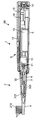
- FIG. 1A and FIG. 1B are views showing the appearance of the electric toothbrush according to the embodiment of the present invention as viewed obliquely from opposite sides. It is a figure which shows the longitudinal cross section when the said electric toothbrush is cut
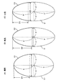
- FIG. 7A shows a “standard” approximate curve which is a part of an ellipse.
- FIG. 7 (B) is a view showing a “long” approximate curve which is a part of another ellipse.
- FIG. 7C is a diagram showing an “small” approximate curve which is a part of yet another ellipse.
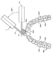
- the main body when the bristles of the head contact with the brushing portion of the dentition with respect to the longitudinal axis (Y axis) of the main body when the bristles of the head contact with the reference position of the dentition in real space Is a diagram for explaining the difference angle ⁇ formed by the vertical axis (Y axis) of It is a figure explaining the process which calculates
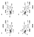
- FIGS. 1-10 When the vertical axis (Y axis) of the main body is in a horizontal posture and viewed from the side of the head (+ Y direction), it is a diagram showing the direction of the gravitational acceleration G output from the acceleration sensor. It is a figure which shows the state by which the head part (+ Y direction) was distribute
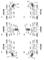
- 13 (A) to 13 (C) are diagrams showing sections for determining which of the front surface, the rear surface, and the meshing surface of the “left back tooth” of the dentition of the upper jaw is brushed.
- 13 (D) to 13 (F) are diagrams showing sections for determining which of the front surface, the rear surface, and the meshing surface of the “left back tooth” of the lower dentition tooth row is brushed.
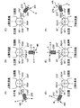
- FIGS. 14 (A) to 14 (B) are diagrams showing sections for determining which of the front surface and the rear surface of the “front teeth” of the upper dentition is brushed.
- FIGS. 14 (C) to 14 (D) are diagrams showing sections for determining which of the front surface and the rear surface of the “front teeth” of the lower dentition is brushed.
- FIGS. 15 (A) to 15 (C) are diagrams showing sections for determining which one of the front surface, the rear surface, and the meshing surface of the “right back tooth” of the dentition of the upper jaw is brushed.
- FIGS. 15 (D) to 15 (F) are diagrams showing sections for determining which one of the front surface, the rear surface, and the meshing surface of the “right back tooth” of the lower jaw tooth row is brushed.
- FIGS. 1 (A) and 1 (B) show the appearance of an electric toothbrush (generally indicated by reference numeral 90) of an embodiment in which the dental plaque detection device of the present invention is incorporated, from diagonally opposite sides. It shows the spot.
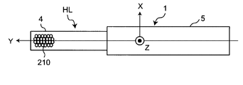
- the electric toothbrush 90 has a head portion 4 on which the hairs 210 are erected, a grip portion 5 to be grasped by hand, and a neck portion 3 connecting the head portion 4 and the grip portion 5 in the longitudinal direction (Y Provided along the axial direction).
- the head portion 4 and the neck portion 3 are integrally configured as a brush member 2 which is detachable from the grip portion 5.
- the head portion 4, the neck portion 3 and the grip portion 5 are collectively referred to as a main body 1.
- the main body 1 has an elongated shape in the Y-axis direction for the convenience of brushing teeth.
- the charger 100 is illustrated in FIG. 1 (A).
- FIG. 2 shows a vertical cross section when the electric toothbrush 90 is cut along the longitudinal axis (Y axis).
- the grip 5 has a stem 6 provided so as to protrude from the outer casing of the grip 5 toward the neck 3.
- the stem 6 has a tubular shape whose tip is closed.
- the neck portion 3 of the brush member 2 is fitted and mounted so as to cover the stem 6. Since the brush member 2 is a consumable part, the brush member 2 is configured to be removable from the grip 5 so that it can be replaced with a new one.
- Hairs (brushes) 210 are erected on one surface (hair raising surface) 4 a of the head portion 4 of the brush member 2 so as to protrude about 10 mm to 12 mm from the hair raising surface 4 a by flocking in this example.
- the hairs 210 may be welded or bonded instead of flocking.
- a power switch S for turning on / off the power is provided on the outer surface of the grip 5 of the main body 1. Further, inside the grip unit 5, a motor 10 as a drive source, a drive circuit 12, a rechargeable battery 13 as a power supply unit, a coil 14 for charging, an acceleration sensor 15, a gyro sensor 16 and the like are mounted. When charging the rechargeable battery 13, charging can be performed in a noncontact manner by electromagnetic induction only by mounting the main body 1 on the charger 100 shown in FIG. 1A.
- a bearing 203 is provided inside the stem 6.
- the tip of an eccentric shaft 30 connected to the rotation shaft 11 of the motor 10 is inserted into the bearing 203.
- the eccentric shaft 30 has a weight 300 near the bearing 203, and the center of gravity of the eccentric shaft 30 is offset from its center of rotation.
- the drive circuit 12 supplies a drive signal (for example, a pulse width modulation signal) according to the operation mode to the motor 10 to rotate the rotary shaft 11 of the motor 10, the eccentric shaft 30 also rotates with the rotation of the rotary shaft 11. .
- the eccentric shaft 30 performs a motion to pivot around the rotation center because the center of gravity is shifted from the rotation center. Therefore, the tip end of the eccentric shaft 30 repeatedly collides with the inner wall of the bearing 203 to vibrate (move) the hair 210 at high speed.
- the acceleration sensor 15 is a commercially available product of a MEMS (Micro Electro Mechanical Systems) type, and outputs a signal representing an acceleration of three axes of X, Y, and Z.
- X, Y, Z indicate orthogonal coordinate systems fixed to the main body 1.
- the X axis is parallel to the napped surface 4 a
- the Y axis is in the direction from the grip 5 to the head 4 in the longitudinal direction of the main body 1.
- the Z axis is set to coincide with the direction from the raised surface 4 a to the tip of the hair 210.
- the gravitational acceleration vector is in the -Y direction, and when the tip of the hair 210 is directed downward, the gravitational acceleration vector is in the + Z direction.
- the output of each axis of the acceleration sensor 15 is input to a control unit 110 described later, and is used to specify a brushing portion (details will be described later).
- the gyro sensor 16 is a commercially available product of MEMS type in this example, and is a signal representing the angular velocity of three axes of X, Y and Z, that is, the angular velocity around Z axis, the angular velocity around X axis and the angular velocity around Y axis Output
- the output of each axis of the gyro sensor 16 is input to a control unit 110 to be described later, and is used together with the output of the acceleration sensor 15 to identify a brushing portion (details will be described later).
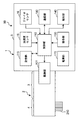
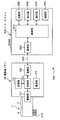
- FIG. 3 shows a block configuration of a control system of the electric toothbrush 90.
- a control unit 110 which forms the above-described drive circuit 12, a storage unit 115, an operation unit 130, and notification A unit 140, a communication unit 180, and a power supply unit 170 are provided.
- the drive part 101 represents the motor 10, the rotating shaft 11, the eccentric shaft 30, the bearing 203, and the weight 300 as stated above.
- the control unit 110 includes a CPU (central processing unit) operated by software in this example, and executes, in addition to the drive of the motor 10, a process for specifying a brushing portion in the dentition and other various processes. Also, the control unit 110 incorporates a timer that measures time.
- a CPU central processing unit
- the operation unit 130 includes the power switch S described above, and serves to turn on / off the power of the electric toothbrush 90 by the user.
- Storage unit 115 includes, in this example, an EEPROM (electrically rewritable non-volatile memory) capable of storing data non-temporarily.
- the storage unit 115 stores a control program for controlling the control unit 110.
- data relating to brushing such as data representing the actual brushing time for each part in the dentition (this is referred to as “actual brushing time data”) in connection with tooth brushing is a table Is stored as (described later).
- the notification unit 140 includes a red LED (Light Emitting Diode) lamp 140R and a green LED lamp 140G (see FIG. 1A), which are predetermined by lighting and extinguishing the LED lamps 140R and 140G. Inform the progress of tooth brushing for the brushing procedure.
- the notification unit 140 may include a buzzer (not shown), and may notify the progress of tooth brushing with respect to the brushing procedure by ringing the buzzer.
- the communication unit 180 is controlled by the control unit 110 to transmit various information (such as actual brushing time data) as a transmission unit to an external device through the network, or to transmit various information from an external device (described later)
- a setting parameter or the like is received as a receiving unit via a network and is passed to the control unit 110.
- Communication via this network is wireless communication (for example, BT (Bluetooth (registered trademark)) communication, BLE (Bluetooth (registered trademark) low energy) communication, etc.) in this example.
- the network is typically a home LAN (Local Area Network), a hospital LAN, but is not limited to this, and may be the Internet or the like.
- the power supply unit 170 includes the rechargeable battery 13 described above, and supplies power (DC voltage in this example) to each part in the electric toothbrush 90.
- upper and lower dentitions 98U and 98L are divided into 16 parts SQ1, SQ2,..., SQ16 (the boundary between adjacent parts is represented by a broken line) ing.).
- the maxillary dentition 98U includes the left buccal site SQ1, the left meshing surface site SQ8, and the left tongue site SQ7 at the left back teeth, and the anterior teeth at the anterior lip site SQ2, the anterior tongue site SQ6.
- the lower jaw teeth row 98L includes a left buccal site SQ9, a left meshing surface site SQ16, and a left tongue site SQ15 at the left back teeth, and an anterior tooth at the anterior lip site SQ10 and the anterior tongue site SQ14. And the right buccal site SQ11, the right meshing surface site SQ12, and the right tongue site SQ13 at the right back tooth.
- the range of the “front teeth” is divided as a range of 20 mm from the reference position BP0 which is the center of the front side to the left and right (that is, the range of 40 mm in width on the left and right).
- the "left back tooth” is divided as a range exceeding 20 mm from the center BP0 on the front side to the left.
- the “right back tooth” is divided as a range exceeding 20 mm from the center BP0 on the front side to the right.
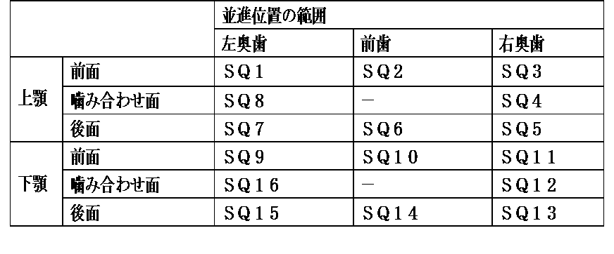
- the upper jaw teeth 98U and the lower jaw teeth 98L are each shown in the following Table 1 according to the combination of the range of translational position along the dental arch and the front, meshing or rear surface. It is divided as follows.
- the surface of Table 1 has a range of translational positions (“left back teeth”, “front teeth”, “right back teeth”) raised on the front head, “front” raised on the front side, “meshing surface”
- the numbers SQ1 to SQ16 of the respective parts determined by the combination with which one of "" and "rear surface” are shown.
- a part (division) corresponding to a combination with the “meshing surface” is not set (it is indicated by a symbol “-”).
- the division of the dentition is not limited to this, and may be a finer division.
- the teeth may be divided into individual teeth along the dental arch, or the individual teeth may be further divided into left and right halves.
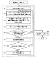
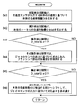
- FIG. 4 shows a schematic flow of processing in which the control unit 110 of the electric toothbrush 90 specifies a brushing portion in the dentition 98U, 98L as a brushing portion detecting method according to one embodiment.
- the brushing is performed in the order of increasing numbers in order from the position SQ1 to SQ8 in the upper denture row 98U shown in FIG. 6, and from the position SQ9 to SQ16 in the lower dentition row 98L.
- the brushing procedure is determined in advance.
- the control unit 110 rotates the motor 10 to vibrate the hair 210.
- the user applies the bristles 210 of the head portion 4 to the reference position BP0 (see FIG. 8) which is the center of the front surface of the dentition 98U. It is assumed that The user can easily align the hair 210 of the head unit 4 with the reference position BP0.
- the control unit 110 starts measuring the brushing time by the built-in timer.
- control unit 110 acts as a brushing portion detection unit, and based on the output of the gyro sensor 16, brushing in the dentition 98U or 98L (initially limited to the upper jaw denture 98U)
- the translational position of the part (represented by the code "BP") is determined (details will be described later).
- the control unit 110 acts as a brushing portion detection unit, and based on the output of the acceleration sensor 15, the bristles 210 of the head unit 4 face around the vertical axis (Y axis) of the main body 1.
- Direction (+ Z direction) is determined, and depending on the direction (+ Z direction) the bristles 210 of the head unit 4 are facing, any one of the front, rear and meshing surfaces of the row of teeth 98U or 98L is brushed It is determined whether it is present (details will be described later).
- step S4 the control unit 110 acts as a brushing portion detection unit, and the translational position of the brushing portion BP determined based on the output of the gyro sensor 16 and the front and rear surfaces of the teeth 98U or 98L.
- the brushing portion BP in the dentition 98U or 98L is specified by the combination with the determination result as to which of the meshing surfaces is being brushed.
- step S5 the control unit 110 determines whether or not the brushing setting period for the identified brushing site BP has elapsed, based on the measurement result of time by the built-in timer. If the brushing setting period for the portion BP has not yet elapsed (NO in step S5), the processing in steps S2 to S5 is repeated. In this example, the control unit 110 repeats the processing of steps S2 to S5 every 0.1 seconds as a processing unit period.
- step S5 when the brushing setting period for the specified brushing site BP has elapsed (YES in step S5), the control unit 110, for example, takes about 0.2 seconds for the green LED lamp 140G included in the notification unit 140.
- step S6 By temporarily turning on, the user is notified that the brushing setting period for the part BP has elapsed (step S6).
- step S7 When the user continues brushing (for example, NO in step S7) although the brushing setting period has been exceeded for one second or more for the portion BP, for example, in order to prevent over-polishing in step S6, for example
- the user may be warned by temporarily turning on the red LED lamp 140R for about 0.2 seconds, for example.
- the progress of the brushing procedure with respect to the brushing procedure may be notified by the ringing of the buzzer included in the notification unit 140.
- control unit 110 controls brushing part BP specified above.
- the actual brushing time for the part BP are recorded in the table prepared in the storage unit 115 as actual brushing time data for each part (step S8).
- the storage unit 115 may also record other information related to brushing.
- step S1 the control unit 110 starts measuring the brushing time by the built-in timer for the “next part”.
- step S9 the process is ended.
- step S2 shown in FIG. 4 the process of determining the translational position of the brushing portion based on the output of the gyro sensor 16
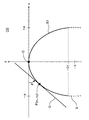
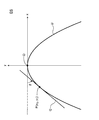
- control unit 110 works as a brushing part detection unit, and as shown in FIG. 9, in the data space DS in which the xy orthogonal coordinate system is defined, a tooth row 98U , 98L, and an approximate curve E1 corresponding to a part of the curved ellipse E is set.
- the approximate curve E1 is set to contact with the x axis in a convex manner at the origin O (0, 0) as a reference point.
- An ellipse E tangent to the x-axis at a point O (0, 0) in a convex manner, with a, b being positive coefficients (ie, a> 0, b> 0), (X / a) 2 + ⁇ (y + b) / b ⁇ 2 1 ...
- step S21 may not be performed each time the process of step S2, but may be performed only once after the power is turned on.
- the data of the approximate curve E1 may be stored in the storage unit 115 in advance.
- the control unit 110 works as a brushing portion detection unit, and as shown in FIG. 8, the dentition 98U or 98L (in the example of FIG. ) In the real space RS where the bristles 210 of the head unit 4 are in contact with the reference position BP0 of the tooth row 98U with respect to the longitudinal axis (Y axis) Y0 of the main body 1
- the difference angle ⁇ formed by the vertical axis (Y axis) Y1 of the main body 1 when the bristles 210 of the head unit 4 are in contact with the brushing site BP is determined based on the output of the gyro sensor 16.
- the user applies the bristles 210 of the head 4 to the reference position BP0 which is the center of the front surface of the dentition 98U. Thereafter, the user applies the bristles 210 of the head 4 to another portion (brushing portion) BP of the dentition 98U or 98L according to the above-mentioned brushing procedure.
- the vertical axis (Y-axis) Y1 of the main body 1 when the 210 is in contact forms an angle (difference angle) ⁇ .
- the control unit 110 obtains the difference angle ⁇ based on the output (angular velocity) of the gyro sensor 16.
- the differential angle ⁇ can be obtained by performing first-order integration.
- the control unit 110 may perform the process of step S21 of FIG. 5 and the process of step S22 in parallel, or may perform the process of step S22 prior to the process of step S21.
- the control unit 110 works as a brushing part detection unit, and as shown in FIG. 9, in the data space DS, the reference position with respect to the approximate curve E1.
- a reference tangent corresponding to the x axis in this example
- a movable tangent that forms a difference angle ⁇ with respect to the reference tangent (x axis) and contacts the approximate curve E1 Set Q.
- the movable tangent line Q is variably set according to the change of the difference angle ⁇ , in other words, according to the change of the brushing portion BP in the tooth row 98U or 98L.
- control unit 110 obtains a point at which the movable tangent Q contacts the approximate curve E1 as the corresponding point P (step S25 in FIG. 5). Thereby, the corresponding point P on the approximate curve E1 can be determined by a relatively simple process.
- a movable tangent line Q is in contact with the approximate curve E1 at a point P (x 1 , y 1 ).
- the coordinates (x 1 , y 1 ) of the corresponding point P corresponding to the brushing portion BP on the approximate curve E 1 in the data space DS Can be found.
- the coordinates (x 1 , y 1 ) of the corresponding point P are data representing the translational position of the brushing portion BP.
- the equation (Eq. 6) is simplified by setting the center of the front surface of the dentition 98U to the reference position BP0.
- the center of the front surface of the row of teeth 98L may be set as the reference position BP0.
- the output of the gyro sensor 16 is an angular velocity
- the vibration component from the drive unit 101 (motor 10) since the output of the gyro sensor 16 is an angular velocity, the differential angle ⁇ can be obtained by performing the first-order integration, and it is difficult to be influenced by noise in the calculation process. Therefore, the translational position of the brushing portion BP in the dentition 98U or 98L can be accurately determined.
- the difference angle ⁇ in the real space RS is 45 °, and accordingly, the coordinates (x 1 , y 1 ) of the corresponding point P in the data space DS ((-17.5, -8.2) (unit mm) If so, the translational position of the brushing site BP belongs to the "front teeth" segment.
- step S3 (Determining which of the front, back, and mating surfaces is brushed)
- step S3 the process of step S3 shown in FIG. 4 (the direction in which the hairs 210 of the head portion 4 are oriented around the longitudinal axis (Y axis) of the main body 1 based on the output of the acceleration sensor 15 (+ Z direction Processing for determining which of the front, rear and meshing surfaces of the row of teeth 98U or 98L is brushed according to the direction (+ Z direction) the bristles 210 of the head unit 4 are facing) Will be described in detail with reference to FIG. 6 and FIGS.
- brushing is performed in the order of increasing numbers from the site SQ1 to SQ8 in the upper denture row 98U, and from SQ9 to SQ16 in the lower dentition row 98L. Furthermore, in the brushing procedure, at the time of brushing of each portion SQ1 to SQ16, the vertical axis (Y axis) of the main body 1 is horizontal as indicated by (HL) or (HR) and parentheses in FIG. 6 respectively. It is assumed that the head portion 4 (in the + Y direction) is oriented leftward or rightward with respect to the user's face in a state where the posture is taken.
- the reference symbol HL indicates that the head 4 (+ Y direction) is disposed leftward with respect to the face of the user, as shown in FIG.
- the code HR represents that the head 4 (+ Y direction) is disposed to the right with respect to the face of the user.
- FIG. 6 when the portions SQ1, SQ7, SQ8, SQ9, SQ15, SQ16 divided as "left back teeth" are brushed, it is set that the head portion 4 (+ Y direction) is disposed in the left direction HL. ing.
- the head portion 4 (+ Y direction) is set to be disposed in the right direction HR.
- These settings are necessarily required when brushing the "left back teeth” and the "right back teeth”, respectively.
- the portions SQ2, SQ6, SQ10 and SQ14 which are classified as "front teeth”, in this example they are set in the same direction as in the brushing of the portions immediately before. That is, when the portions SQ2 and SQ10 are brushed, it is set that the head portion 4 (+ Y direction) is disposed in the leftward direction HL. Further, when the portions SQ6 and SQ14 are brushed, it is set that the head portion 4 (+ Y direction) is disposed in the right direction HR.
- FIG. 10 shows the direction of the gravitational acceleration G output from the acceleration sensor 15 when viewed from the side of the head unit 4 (+ Y direction) with the vertical axis (Y axis) of the main body 1 taken in a horizontal posture. It shows.
- the direction (+ Z direction) that the hairs 210 of the head portion 4 are directed around the longitudinal axis (Y axis) of the main body 1 Is expressed as a rotation angle ⁇ around the vertical axis.
- the rotational angle ⁇ around the vertical axis is 0 ° vertically downward, and the vertical axis (Y axis) of the main body 1 takes a horizontal posture as shown in FIG. When viewed from the (+ Y direction), take a value within the range of 0 ° to 359.99 ° (up to two decimal places) counterclockwise.
- FIGS. 13 (A) to 13 (C) show sections for determining which of the front surface, the rear surface and the meshing surface of the “left back tooth” of the upper row of teeth 98U is brushed.
- the vertical axis (Y-axis) of the main body 1 takes a horizontal posture, and the head 4 (+ Y direction) is oriented leftward to the user's face, as shown in FIG. 13A. If the rotation angle ⁇ about the axis is in the range of 90 ° to 135 °, it is determined that the front surface (and hence the left buccal region) SQ1 is brushed. In that state, as shown in FIG.
- FIGS. 13D to 13F show sections for determining which of the anterior, posterior, and meshing surfaces of the left back tooth of the lower dentition row 98L is brushed.
- the vertical axis (Y-axis) of the main body 1 takes a horizontal posture, and the head portion 4 (+ Y direction) is arranged in the left direction HL with respect to the user's face, as shown in FIG. If the rotation angle ⁇ about the axis is in the range of 45 ° to 90 °, it is determined that the front surface (and hence the left buccal region) SQ9 is brushed. In that state, as shown in FIG.
- FIGS. 14 (A) to 14 (B) show sections for determining which of the front and back surfaces of the “front teeth” of the upper tooth denture 98U is brushed.
- the vertical axis (Y axis) of the main body 1 takes a horizontal posture, and the head 4 (+ Y direction) is arranged in the left direction HL with respect to the user's face, as shown in FIG. If the rotation angle ⁇ about the axis is in the range of 90 ° to 180 °, it is determined that the front surface (and hence the front lip side portion) SQ2 is brushed.
- FIGS. 14 (C) to 14 (D) show sections for determining which of the front surface and the rear surface of the “front teeth” of the lower row of teeth 98L is brushed.
- the vertical axis (Y axis) of the main body 1 takes a horizontal posture, and the head 4 (+ Y direction) is disposed in the left direction HL with respect to the user's face, as shown in FIG. If the rotation angle ⁇ about the axis is in the range of 0 ° to 90 °, it is determined that the front surface (and hence the front lip side portion) SQ10 is brushed.
- FIGS. 15 (A) to 15 (C) show sections for determining which of the front surface, the rear surface and the meshing surface of the “right back tooth” of the upper row of teeth 98U is brushed.
- the vertical axis (Y axis) of the main body 1 takes a horizontal posture and the head 4 (+ Y direction) is arranged in the right direction HR with respect to the user's face, as shown in FIG. If the rotation angle ⁇ about the axis is in the range of 90 ° to 135 °, it is determined that the back surface (and hence the right tongue side portion) SQ5 is brushed. In that state, as shown in FIG.
- FIGS. 15 (D) to 15 (F) show sections for determining which of the front, back and meshing surfaces of the “right back tooth” of the lower row of teeth 98L is brushed.
- the vertical axis (Y axis) of the main body 1 takes a horizontal posture, and the head 4 (+ Y direction) is oriented rightward HR with respect to the face of the user, as shown in FIG. If the rotation angle ⁇ about the axis is in the range of 45 ° to 90 °, it is determined that the rear surface (and hence the right tongue side portion) SQ13 is brushed. In that state, as shown in FIG.
- the correspondence relationship between the rotation angle ⁇ around the vertical axis and the front surface, rear surface, and meshing surface is as shown in Table 2 below.
- the surface of Table 2 shows the rotation angle ⁇ around the vertical axis when the head 4 (+ Y direction) is disposed in the leftward direction HL or the rightward direction HR.
- the front side of Table 2 is the front, meshing surface, back surface, front surface of the "front teeth", rear surface of the "left back teeth” of the upper jaw teeth 98U or lower jaw teeth 98L corresponding to the rotation angle ⁇ around the vertical axis ,
- the symbol "-" in the surface of Table 2 indicates that brushing can not occur.
- the rotation angle ⁇ in parentheses () indicates that brushing can occur but deviates from the brushing procedure described above. (Table 2) Correspondence between the rotation angle ⁇ around the vertical axis and the front, rear, and mating surfaces
- the control unit 110 sets the direction (+ Z direction) in which the hairs 210 of the head unit 4 face around the longitudinal axis (Y axis) of the main body 1 around the longitudinal axis. It is determined as the rotation angle ⁇ , and depending on the rotation angle ⁇ around the longitudinal axis, it can be determined which of the front surface, the rear surface and the meshing surface of the tooth row 98U or 98L is brushed.
- the control unit 110 determines that the translational position of the brushing portion BP determined based on the output of the gyro sensor 16 and either the front surface, the rear surface, or the meshing surface of the teeth 98U or 98L are brushed.
- the brushing portion BP in the dentition 98U or 98L can be specified by the combination with the determination result of whether it is being done. This makes it possible to specify the brushing portion BP in the dentition 98U or 98L with high accuracy.
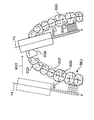
- the user during tooth brushing does not substantially change the orientation of the vertical axis (Y axis) of the main body 1, for example, as shown in FIG. As indicated by MV2, there is a case where the main body 1 is largely translated and moved over from the left buccal site SQ1 to the right tongue site SQ5.
- the process of step S2 shown in FIG. An error occurs in the process of determining the translational position of the brushing site based on the output of the sensor 16).
- control unit 110 performs the correction process shown in the flow of FIG. 18 while repeating the processes of steps S2 to S5 in FIG.
- the control unit 110 performs second-order integration on the basis of the acceleration of the main body 1 output by the acceleration sensor 15 every 0.1 seconds as a processing unit period.
- the translational movement amount is represented by Acc_X, Acc_Y, Acc_Z
- velocity in the three axis directions is represented by v_X, v_Y, v_Z, respectively
- translation amount of the main body 1 in three axis directions is D_X, It is represented by D_Y and D_Z.
- step S42 the control unit 110 tabulates the translational movement amount Di of the main body 1 every 0.5 seconds as a preset tabulation unit period.
- the translational movement amount Di for each processing unit period is represented as D1, D2, D3, D4, D5
- the total translational movement amount D_total for a certain aggregation unit period is given by the following equation (Eq .10).
- D_total D1 + D2 + D3 + D4 + D5 ... (Eq. 10)
- step S43 the control unit 110 determines whether or not the total translational movement amount D_total is smaller than or equal to a predetermined first threshold value ⁇ 1 for a certain aggregation unit period.
- ⁇ 1 20 mm is set.
- the control unit 110 proceeds to step S44, and in the total unit period, the translational position of the brushing portion BP obtained based on the output of the gyro sensor 16 Is maintained (first correction processing).
- the user during tooth brushing substantially stops the translational movement of the main body 1 (particularly, the head portion 4), the longitudinal axis (Y axis) of the main body 1
- the translational position of the brushing portion BP obtained based on the output of the gyro sensor 16 is maintained before and after the change. Thereby, the accuracy of the determined translational position of the brushing portion BP can be maintained.
- the division of the dentition is more finely divided than that of Table 1, for example, when divided into individual teeth along the dental arch, the individual teeth are further divided into left and right halves. Accordingly, it is desirable to set the value of the first threshold ⁇ 1 smaller, for example, 10 mm or 5 mm, accordingly.
- step S45 the control unit 110 performs total for the total unit period. It is determined whether or not the translational movement amount D_total is equal to or greater than a predetermined second threshold value ⁇ 2.
- D_total ⁇ ⁇ 2 YES in step S45
- the control unit 110 shifts to a portion corresponding to the translational movement destination of the main body 1 on the approximate curve E1 in the data space DS.
- the corresponding point P is determined again based on the output (second correction process).
- the position is jumped from the left buccal site SQ1 to the right tongue site SQ5, for example, in the denture row 98U of the upper jaw, while hardly changing the direction of the longitudinal axis (Y axis) of the main body 1
- the control unit 110 shifts the x coordinate from a point near -a to a point near + a on the approximate curve E1 in the data space DS shown in FIG. Then, the corresponding point P is determined again based on the output (difference angle ⁇ ) of the gyro sensor 16.
- the translational position of the brushing portion BP in the dentition 98U or 98L can be accurately determined.
- the second-order integration is performed based on the output of the acceleration sensor 15 to calculate the translational movement amount Di of the main body 1 for each processing unit period. Therefore, it can be said that the calculated total translational movement amount D_total of the main body 1 is not accurate due to the influence of noise. However, the calculated total translational movement amount D_total of the main body 1 is extremely large (step S43 in FIG. 18) or almost no translational movement amount of the main body 1 (particularly, the head unit 4) There is no problem in using it for the determination of S45).
- control unit 110 determines that there is no need for correction, and the flow of FIG. The process returns to steps S2 to S5).
- the “standard” approximate curve E1 which is a part of the ellipse E shown in FIG. 7A, was used to determine the translational position of the brushing site BP.
- the minor diameter 2a ′ 60.43 mm.
- a portion with a depth D2 ⁇ 60 mm and a width W2 ⁇ 60 mm may be used as the approximate curve E2.
- the minor diameter 2a ′ ′ 62.21 mm
- the major diameter 2b ′ ′ 135.
- a portion with a depth D3 ⁇ 50 mm and a width W3 ⁇ 60 mm may be used as the approximate curve E3.
- the actual brushing time data for each part acquired by the control unit 110 and other data related to brushing may be transmitted to the outside of the main body 1 through the communication unit 180 as a transmission unit.
- the data can be received by a computer device provided outside the main body 1 and used for various processes and applications.
- the dental arch of the subject in the real space RS is approximated by a curve (approximated curve E1, E2 or E3) corresponding to a part of the ellipse E in the data space DS. Absent.
- the dental arch of the subject in real space RS may be approximated by a parabola U in data space DS.
- the parabola U contacts the x axis in a convex manner at the origin O (0, 0).
- an approximate curve can be set by defining the coefficient p. Therefore, the process of obtaining the corresponding point P can be easily performed.
- FIG. 20 illustrates the configuration of a system (generally indicated by reference numeral 700) including the electric toothbrush 90 and the smartphone 600 described above.
- the system 700 includes an electric toothbrush 90 and a smartphone 600 as a computer device so as to be able to wirelessly communicate with each other via a network 900.
- the smartphone 600 includes a main body 600M, and a control unit 610, a storage unit 620, an operation unit 630, a display 640, a communication unit 680, and a power supply unit 690 mounted on the main body 600M.
- the smartphone 600 is a commercially available smartphone on which application software described later is installed.
- Control unit 610 includes a CPU and its auxiliary circuit, controls each unit of smartphone 600, and executes processing in accordance with programs and data stored in storage unit 620. For example, based on an instruction input through the operation unit 630, the data input from the communication unit 680 is processed, and the processed data is stored in the storage unit 620, displayed on the display 640, or communicated. Output via the unit 680.
- Storage unit 620 includes a RAM (Random Access Memory) used as a work area necessary for executing a program in control unit 610, and a ROM (Read) for storing a basic program to be executed by control unit 610. And “Only Memory”.
- a semiconductor memory memory card, SSD (Solid State Drive) or the like may be used as a storage medium of an auxiliary storage device for assisting the storage area of the storage unit 620.
- the operation unit 630 is, in this example, a touch panel provided on the display 640.
- a keyboard or other hardware operation device may be included.
- the display 640 includes a display screen which is an LCD (liquid crystal display element) or an organic EL (electroluminescence) display in this example.
- the display 640 displays various images on the display screen according to the control of the control unit 610.
- Communication unit 680 is configured to be capable of wireless communication (for example, BT communication, BLE communication, and the like) with electric toothbrush 90 via network 900 according to control by control unit 610.
- wireless communication for example, BT communication, BLE communication, and the like
- the power supply unit 690 includes a rechargeable battery in this example, and supplies power to each unit of the smartphone 600.
- the electric toothbrush program performs wireless communication with the electric toothbrush 90 to make various settings regarding the brushing procedure and the like on the electric toothbrush 90, data for specifying the brushing part BP from the electric toothbrush 90, and translation of the brushing part It is a program that receives the position (coordinate value), the direction in which the hair 210 of the head unit 4 is facing, the output value of the gyro sensor or the acceleration sensor, and the like and uses them for various processes.
- minor axis and major axis of the selected ellipse, and the dimensions (depth and width) of the portion of the selected ellipse used as the approximate curve are set by changing them continuously on the screen of the display 640. It may be possible.
- the specified brushing site BP is associated with the actual brushing time for the site BP, and the actual brushing time data for each site is provided in the table provided in the storage unit 115. It is recorded as In this example, as shown in Table 3, the actual brushing time is 7.2 seconds for the site SQ1 in the upper denture row 98U, 3.7 seconds for the site SQ2, and 6.9 seconds for the site SQ3. The value was .... The lower jaw tooth row 98L had values of 5 seconds for the portion SQ9, 4.6 seconds for the portion SQ10, 6.6 seconds for the portion SQ11, and so on.
- control unit 610 of smartphone 600 receives data (including actual brushing time data for each part) recorded in the table of storage unit 115 from electric toothbrush 90 via communication unit 680.
- the control unit 610 works as a brushing evaluation unit, and calculates an evaluation value (brushing evaluation value) representing the degree of agreement with the brushing procedure based on the actual brushing time data for each part.
- the brushing evaluation values are 90% for the part SQ1, 93% for the part SQ2, 77% for the part SQ3, ... in the upper denture row 98U. Further, in the lower dentition 98L, the value is 100% for the part SQ9, 92% for the part SQ10, 94% for the part SQ11, and so on.
- control unit 610 of smartphone 600 causes the display screen of display 640 to display these brushing evaluation values.
- the user can view the display screen of the display 640 to know the degree of matching or non-matching of his or her brushing procedure with the brushing procedure.
- the brushing procedure tends to be inconsistent with the above brushing procedure, for example, the tendency of the back surface of the left back tooth (section SQ7) and the back surface of the right back tooth (section SQ5) to be insufficiently brushed. be able to.
- users can improve their brushing practices.
- control part 110 of electric toothbrush 90 performed a function of a brushing part detection part, it is not restricted to this. While communicating between the electric toothbrush 90 and the smartphone 600 while brushing teeth, the control unit 610 of the smartphone 600 may execute part or all of the functions of the brushing part detection unit. In such a case, the configuration of the control unit 110 of the electric toothbrush 90 can be simplified. Thus, the control unit 110 can be configured by, for example, a logic IC (integrated circuit) instead of the CPU.
- control unit 110 of the electric toothbrush 90 performs basic identification (flow in FIG. 4, particularly steps S2 and S3) of the brushing portion BP in the function of the brushing portion detection unit
- control unit 610 of the smartphone 600 corrects A process (flow of FIG. 18) may be performed.
- the processing load can be distributed between the electric toothbrush 90 and the smartphone 600.
- a device such as a tablet terminal or a personal computer that substantially functions as a computer device may be used.
- the method of processing executed by the control unit 110 of the electric toothbrush 90 or the control unit 610 of the smartphone 600 described above is, as application software (computer program), CD (compact disc), DVD (digital universal disc), flash memory, etc.
- a non-transitory data can be recorded on a recordable storage medium.
- an xyz orthogonal coordinate system may be set in the data space, and an approximate curve inclined with respect to the horizontal xy plane may be set.
Landscapes
- Health & Medical Sciences (AREA)
- Life Sciences & Earth Sciences (AREA)
- Dentistry (AREA)
- Veterinary Medicine (AREA)
- Public Health (AREA)
- General Health & Medical Sciences (AREA)
- Animal Behavior & Ethology (AREA)
- Epidemiology (AREA)
- Engineering & Computer Science (AREA)
- Remote Sensing (AREA)
- Radar, Positioning & Navigation (AREA)
- General Physics & Mathematics (AREA)
- Physics & Mathematics (AREA)
- Biophysics (AREA)
- Brushes (AREA)
Abstract
この発明の電動歯ブラシは、ヘッド部(4)とネック部(3)とグリップ部(5)を縦軸方向に沿って有する本体(1)の内部に、本体(1)の角速度を検知するジャイロセンサ(16)を備える。歯列の基準位置(BPO)にヘッド部(4)の毛が接するときの本体(1)の縦軸に対して、歯列のブラッシング部位(BP)にヘッド部(4)の毛が接するときの本体(1)の縦軸がなす角度(θ)を、ジャイロセンサ(16)の出力に基づいて求める。角度(θ)に基づいて、歯列に対応して湾曲した近似曲線(E1)上においてブラッシング部位(BP)に対応する対応点(P)を求めて、その対応点(P)の座標をブラッシング部位(BP)の並進位置(P)とする。
Description
この発明は、歯列におけるブラッシング部位を検出することが可能な電動歯ブラシ、システムおよびブラッシング部位検出方法に関する。
また、この発明は、そのようなブラッシング部位検出方法をコンピュータに実行させるためのプログラムに関する。
従来、例えば特許文献1(特開2009-240759号公報)に開示されている電動歯ブラシでは、歯ブラシ本体に加速度センサを備え、この加速度センサの出力から得られるx軸方向、y軸方向、z軸方向それぞれの動加速度成分を二階積分することにより、x軸方向、y軸方向、z軸方向それぞれの移動量を算出して、歯磨き中に歯列におけるブラッシング部位(同文献では、歯列がなす平面内における並進位置を指す。)を求めている。
また、同文献では、加速度センサが出力から得られる重力加速度成分に基づいて、歯ブラシの縦軸(y軸)の周りの向き(同文献では、これを「ブラシ角」と呼んでいる。)を求めることが開示されている。または、歯ブラシ本体にさらにジャイロセンサ(ジャイロスコープ)を備え、ジャイロセンサの出力を累積加算(積分)することにより、ブラシ角を求めることも開示されている。このようにして求められたブラシ角に基づいて、歯の前面、後面、噛み合わせ面のうちいずれがブラッシングされているかを知ることができる。
阪勉、「口蓋の形態変異の成因に関する因子分析学的研究―顎顔面頭蓋形態との関連において―」、日本口腔外科学会雑誌、Vol.34、No.3、p451-469、1988年3月
しかしながら、特許文献1の電動歯ブラシでは、加速度センサの出力に、ブラシ(毛)を振動させる駆動モータからの振動成分がノイズとして含まれてしまう。また、ブラッシング部位の並進位置を求めるために、加速度センサの出力から得られる動加速度成分を二階積分しているため、演算過程でノイズの影響を大きく受ける。このため、求められたブラッシング部位の並進位置の精度が良くない、という問題がある。
そこで、この発明の課題は、歯列におけるブラッシング部位の並進位置を精度良く求めることができる電動歯ブラシ、システムおよびブラッシング部位検出方法を提供することにある。
また、この発明の課題は、そのようなブラッシング部位検出方法をコンピュータに実行させるためのプログラムを提供することにある。
上記課題を解決するため、この発明の電動歯ブラシは、
毛が立設された起毛面を有するヘッド部、手で握られるべきグリップ部、および、上記ヘッド部と上記グリップ部とを連結するネック部を、縦軸方向に沿って有する本体と、
上記本体の内部に搭載され、上記本体の角速度を検知するジャイロセンサと、
上記ジャイロセンサの出力に基づいて、歯列におけるブラッシング部位の並進位置を求めるブラッシング部位検出部とを備え、
上記ブラッシング部位検出部は、
上記歯列の基準位置に上記ヘッド部の毛が接するときの上記本体の縦軸に対して、上記歯列のブラッシング部位に上記ヘッド部の毛が接するときの上記本体の縦軸がなす角度を、上記ジャイロセンサの出力に基づいて求め、
上記角度に基づいて、上記歯列に対応して湾曲した近似曲線上において上記ブラッシング部位に対応する対応点を求めて、その対応点の座標を上記ブラッシング部位の並進位置とすることを特徴とする。
毛が立設された起毛面を有するヘッド部、手で握られるべきグリップ部、および、上記ヘッド部と上記グリップ部とを連結するネック部を、縦軸方向に沿って有する本体と、
上記本体の内部に搭載され、上記本体の角速度を検知するジャイロセンサと、
上記ジャイロセンサの出力に基づいて、歯列におけるブラッシング部位の並進位置を求めるブラッシング部位検出部とを備え、
上記ブラッシング部位検出部は、
上記歯列の基準位置に上記ヘッド部の毛が接するときの上記本体の縦軸に対して、上記歯列のブラッシング部位に上記ヘッド部の毛が接するときの上記本体の縦軸がなす角度を、上記ジャイロセンサの出力に基づいて求め、
上記角度に基づいて、上記歯列に対応して湾曲した近似曲線上において上記ブラッシング部位に対応する対応点を求めて、その対応点の座標を上記ブラッシング部位の並進位置とすることを特徴とする。
本明細書で、「ブラッシング部位」とは、口腔内の歯列の表面を区分することで定義される複数の部位のうち、上記毛でブラッシングされている(毛が当たっている)部位をいう。歯列におけるブラッシング部位は、歯列が存在する実空間内での並進位置と、歯列の前面、後面、噛み合わせ面のうちいずれがブラッシングされているかとの組合せによって特定されるものとする。
歯列の「基準位置」とは、上記歯列において、上記角度が測られる基準となる或る位置を指す。
この発明の電動歯ブラシでは、ブラッシング部位検出部が、ジャイロセンサの出力に基づいて、歯列におけるブラッシング部位の並進位置を求める。すなわち、上記ブラッシング部位検出部は、上記歯列の基準位置に上記ヘッド部の毛が接するときの上記本体の縦軸に対して、上記歯列のブラッシング部位に上記ヘッド部の毛が接するときの上記本体の縦軸がなす角度を、上記ジャイロセンサの出力に基づいて求める。次に、上記角度に基づいて、上記歯列に対応して湾曲した近似曲線上において上記ブラッシング部位に対応する対応点を求めて、その対応点の座標を上記ブラッシング部位の並進位置とする。
このようにした場合、上記ジャイロセンサの出力は角速度であるから、ブラシ(毛)を振動させる駆動モータからの振動成分がノイズとして含まれ難い。また、上記ジャイロセンサの出力は角速度であるから、一階積分すれば上記角度を求めることができ、演算過程でノイズの影響を受け難い。したがって、歯列におけるブラッシング部位の並進位置を精度良く求めることができる。
一実施形態の電動歯ブラシでは、上記ブラッシング部位検出部は、上記近似曲線に対して上記基準位置に対応した基準点で接する基準接線を設定するとともに、上記基準接線に対して上記角度をなし、かつ上記近似曲線に接する可動接線を設定し、上記近似曲線に上記可動接線が接する点を上記対応点として求めることを特徴とする。
ここで、「可動接線」とは、上記角度の変化に伴って、言い換えれば、上記歯列におけるブラッシング部位の変化に伴って、可変して設定される接線を意味する。
この一実施形態の電動歯ブラシでは、上記ブラッシング部位検出部は、上記近似曲線に対して上記基準位置に対応した基準点で接する基準接線を設定するとともに、上記基準接線に対して上記角度をなし、かつ上記近似曲線に接する可動接線を設定する。そして、上記近似曲線に上記可動接線が接する点を上記対応点として求める。これにより、上記近似曲線上の上記対応点を、比較的簡単な処理で求めることができる。
一実施形態の電動歯ブラシでは、上記歯列の基準位置は、上記歯列の前面の中央であることを特徴とする。
この一実施形態の電動歯ブラシでは、上記歯列の基準位置は、上記歯列の前面の中央であるから、ユーザが歯磨きを開始する部位として上記ヘッド部の毛を合わせ易い。また、上記ブラッシング部位検出部が上記ブラッシング部位の並進位置を解析的な式で簡単に求めることができる。
一実施形態の電動歯ブラシでは、上記ブラッシング部位検出部は、xy直交座標系が定められたデータ空間内に、上記近似曲線を、正の係数aおよびbを用いて、関数y=b[{1-(x/a)2}1/2-1]で表される楕円の一部に相当する曲線として設定することを特徴とする。
歯科分野で知られているように、歯列弓は楕円の一部で近似され得る(非特許文献1)。そこで、この一実施形態の電動歯ブラシでは、上記ブラッシング部位検出部は、xy直交座標系が定められたデータ空間内に、上記近似曲線を、正の係数aおよびbを用いて、関数y=b[{1-(x/a)2}1/2-1]で表される楕円の一部に相当する曲線として設定する。このようにした場合、係数a,bを定めることによって上記近似曲線を実際の歯列に近似した態様に設定できる。したがって、上記近似曲線上で、上記ブラッシング部位の並進位置を表す対応点を精度良く求めることが可能になる。
一実施形態の電動歯ブラシでは、上記ブラッシング部位検出部は、xy直交座標系が定められたデータ空間内に、上記近似曲線を、負の係数pを用いて、関数4py=x2で表される放物線として設定することを特徴とする。
歯科分野で知られているように、歯列弓は放物線でも近似され得る(非特許文献1)。そこで、この一実施形態の電動歯ブラシでは、上記ブラッシング部位検出部は、xy直交座標系が定められたデータ空間内に、上記近似曲線を、負の係数pを用いて、関数4py=x2で表される放物線として設定する。このようにした場合、係数pを定めることによって上記近似曲線を設定できる。したがって、上記対応点を求める処理を簡単に行うことができる。
一実施形態の電動歯ブラシでは、
上記本体の外部から設定パラメータを受信可能な受信部を備え、
上記ブラッシング部位検出部は、上記受信部を通して受信した設定パラメータに応じて、上記係数aおよびbまたは上記係数pを可変して設定可能になっていることを特徴とする。
上記本体の外部から設定パラメータを受信可能な受信部を備え、
上記ブラッシング部位検出部は、上記受信部を通して受信した設定パラメータに応じて、上記係数aおよびbまたは上記係数pを可変して設定可能になっていることを特徴とする。
この一実施形態の電動歯ブラシでは、上記本体の外部から設定パラメータを受信可能な受信部を備える。上記ブラッシング部位検出部は、上記受信部を通して受信した設定パラメータに応じて、上記係数aおよびbまたは上記係数pを可変して設定可能になっている。したがって、様々なユーザの歯列弓のサイズと形状に応じて、上記近似曲線を適切に設定することができる。そのようにした場合、歯列におけるブラッシング部位の並進位置をさらに精度良く求めることができる。
一実施形態の電動歯ブラシでは、
上記本体の内部に搭載された加速度センサを備え、
上記ブラッシング部位検出部は、上記ジャイロセンサの出力と上記加速度センサの出力に基づいて、上記歯列におけるブラッシング部位を特定することを特徴とする。
上記本体の内部に搭載された加速度センサを備え、
上記ブラッシング部位検出部は、上記ジャイロセンサの出力と上記加速度センサの出力に基づいて、上記歯列におけるブラッシング部位を特定することを特徴とする。
この一実施形態の電動歯ブラシでは、上記ブラッシング部位検出部は、上記ジャイロセンサの出力と上記加速度センサの出力に基づいて、上記歯列におけるブラッシング部位を特定する。これにより、歯列におけるブラッシング部位を精度良く特定することができる。
一実施形態の電動歯ブラシでは、
上記ブラッシング部位検出部は、
上記加速度センサが出力する重力加速度の向きに基づいて上記本体の縦軸の周りで上記ヘッド部の毛が向いている向きを求め、上記ヘッド部の毛が向いている向きに応じて上記歯列の前面、後面、噛み合わせ面のうちいずれがブラッシングされているかを判定し、
上記ジャイロセンサの出力に基づいて求められた上記ブラッシング部位の並進位置と、上記歯列の前面、後面、噛み合わせ面のうちいずれがブラッシングされているかの判定結果との組合せによって、上記歯列におけるブラッシング部位を特定することを特徴とする。
上記ブラッシング部位検出部は、
上記加速度センサが出力する重力加速度の向きに基づいて上記本体の縦軸の周りで上記ヘッド部の毛が向いている向きを求め、上記ヘッド部の毛が向いている向きに応じて上記歯列の前面、後面、噛み合わせ面のうちいずれがブラッシングされているかを判定し、
上記ジャイロセンサの出力に基づいて求められた上記ブラッシング部位の並進位置と、上記歯列の前面、後面、噛み合わせ面のうちいずれがブラッシングされているかの判定結果との組合せによって、上記歯列におけるブラッシング部位を特定することを特徴とする。
この一実施形態の電動歯ブラシでは、上記ブラッシング部位検出部は、上記加速度センサが出力する重力加速度の向きに基づいて上記本体の縦軸の周りで上記ヘッド部の毛が向いている向きを求め、上記ヘッド部の毛が向いている向きに応じて上記歯列の前面、後面、噛み合わせ面のうちいずれがブラッシングされているかを判定する。そして、上記ジャイロセンサの出力に基づいて求められた上記ブラッシング部位の並進位置と、上記歯列の前面、後面、噛み合わせ面のうちいずれがブラッシングされているかの判定結果との組合せによって、上記歯列におけるブラッシング部位を特定する。これにより、歯列におけるブラッシング部位を精度良く特定することができる。
一実施形態の電動歯ブラシでは、
上記ブラッシング部位検出部は、
予め定められた集計単位期間毎に、上記加速度センサが出力する上記本体の加速度に基づいて上記本体の並進移動量を算出し、
或る集計単位期間について、上記本体の並進移動量が予め定められた第1閾値以下であるとき、その集計単位期間では、上記ジャイロセンサの出力に基づいて求められた上記ブラッシング部位の並進位置を維持する第1の補正処理を行うことを特徴とする。
上記ブラッシング部位検出部は、
予め定められた集計単位期間毎に、上記加速度センサが出力する上記本体の加速度に基づいて上記本体の並進移動量を算出し、
或る集計単位期間について、上記本体の並進移動量が予め定められた第1閾値以下であるとき、その集計単位期間では、上記ジャイロセンサの出力に基づいて求められた上記ブラッシング部位の並進位置を維持する第1の補正処理を行うことを特徴とする。
本明細書で、予め定められた集計単位期間での、上記本体の「並進移動量」、上記本体の縦軸の向きの「変化量」とは、それぞれ、その集計単位期間におけるトータルの並進移動量、トータルの変化量を意味する。
この一実施形態の電動歯ブラシでは、上記ブラッシング部位検出部は、予め定められた集計単位期間毎に、上記加速度センサが出力する上記本体の加速度に基づいて上記本体の並進移動量を算出する。そして、上記ブラッシング部位検出部は、或る集計単位期間について、上記本体の並進移動量が予め定められた第1閾値以下であるとき、その集計単位期間では、上記ジャイロセンサの出力に基づいて求められた上記ブラッシング部位の並進位置を維持する第1の補正処理を行う。したがって、例えば、歯磨き中のユーザが、上記本体(特に、ヘッド部)の並進移動を殆ど止めた状態で、上記本体の縦軸の向きを大きく変化させたような場合に、その変化の前後で、上記ジャイロセンサの出力に基づいて求められた上記ブラッシング部位の並進位置が維持される。これにより、求められた上記ブラッシング部位の並進位置の精度が維持され得る。
一実施形態の電動歯ブラシでは、
上記ブラッシング部位検出部は、
予め定められた集計単位期間毎に、上記加速度センサが出力する上記本体の加速度に基づいて上記本体の並進移動量を算出し、
上記本体の並進移動量が予め定められた第2閾値以上であるとき、上記近似曲線上における上記本体の並進移動先に相当する部分へシフトして、上記ジャイロセンサの出力に基づいて上記対応点を求め直す第2の補正処理を行うことを特徴とする。
上記ブラッシング部位検出部は、
予め定められた集計単位期間毎に、上記加速度センサが出力する上記本体の加速度に基づいて上記本体の並進移動量を算出し、
上記本体の並進移動量が予め定められた第2閾値以上であるとき、上記近似曲線上における上記本体の並進移動先に相当する部分へシフトして、上記ジャイロセンサの出力に基づいて上記対応点を求め直す第2の補正処理を行うことを特徴とする。
この一実施形態の電動歯ブラシでは、上記ブラッシング部位検出部は、予め定められた集計単位期間毎に、上記加速度センサが出力する上記本体の加速度に基づいて上記本体の並進移動量を算出する。そして、上記ブラッシング部位検出部は、上記本体の並進移動量が予め定められた第2閾値以上であるとき、上記近似曲線上における上記本体の並進移動先に相当する部分へシフトして、上記ジャイロセンサの出力に基づいて上記対応点を求め直す第2の補正処理を行う。したがって、歯磨き中のユーザが、上記本体の縦軸の向きを殆ど変化させることなく、例えば上顎の歯列において左頬側部位から右頬側部位へ前唇側部位を飛び越えて上記本体を並進移動させたような場合に、歯列におけるブラッシング部位の並進位置を精度良く求めることができる。
なお、上記集計単位期間毎に、上記第1の補正処理と上記第2の補正処理との両方を行うのが望ましい。
一実施形態の電動歯ブラシでは、ブラッシングに関するデータを、上記本体の外部へ送信可能な送信部を備えたことを特徴とする。
本明細書で、「ブラッシングに関するデータ」とは、部位毎の実ブラッシング時間データ(特定されたブラッシング部位とその部位についての実際のブラッシング時間とを対応付けたデータ)や、その他ブラッシングに関するデータを広く含む。
この一実施形態の電動歯ブラシでは、送信部は、ブラッシングに関するデータを、上記本体の外部へ送信することができる。この場合、例えば、上記データを上記本体の外部に設けられたコンピュータ装置によって受信して、様々な処理、用途に用いることができる。
別の局面では、この発明のシステムは、上記電動歯ブラシと、この電動歯ブラシの本体の外部に設けられたコンピュータ装置とを、互いに通信可能に含む。
「コンピュータ装置」とは、名称の如何を問わず、実質的にコンピュータとして動作すれば足りる。例えば、スマートフォン、タブレット端末などであってもよい。
一実施形態のシステムでは、
上記歯列における複数の部位を予め定められた順序で、かつ、それぞれ予め定められたブラッシング設定期間だけブラッシングしてゆくブラッシング手順が定められており、
上記ブラッシング部位検出部によって特定されたブラッシング部位に基づいて、上記ブラッシング手順に対する一致の程度を表す評価値を算出するブラッシング評価部を備えたことを特徴とする。
上記歯列における複数の部位を予め定められた順序で、かつ、それぞれ予め定められたブラッシング設定期間だけブラッシングしてゆくブラッシング手順が定められており、
上記ブラッシング部位検出部によって特定されたブラッシング部位に基づいて、上記ブラッシング手順に対する一致の程度を表す評価値を算出するブラッシング評価部を備えたことを特徴とする。
この一実施形態のシステムでは、上記歯列における複数の部位を予め定められた順序で、かつ、それぞれ予め定められたブラッシング設定期間だけブラッシングしてゆくブラッシング手順が定められている。ここで、ブラッシング評価部は、上記ブラッシング部位検出部によって特定されたブラッシング部位に基づいて、上記ブラッシング手順に対する一致の程度を表す評価値を算出する。したがって、ユーザは、この評価値に基づいて、上記ブラッシング手順に対する一致(または不一致)の程度を知ることができる。
別の局面では、この発明のブラッシング部位検出方法は、
歯列において電動歯ブラシによってブラッシングされるブラッシング部位を検出するブラッシング部位検出方法であって、
上記電動歯ブラシは、
毛が立設された起毛面を有するヘッド部、手で握られるべきグリップ部、および、上記ヘッド部と上記グリップ部とを連結するネック部を、縦軸方向に沿って有する本体と、
上記本体の内部に搭載され、上記本体の角速度を検知するジャイロセンサとを備え、
上記ブラッシング部位検出方法は、
上記歯列が存在する実空間内で、上記歯列の基準位置に対して上記ヘッド部の毛が接するときの上記本体の縦軸に対して、上記歯列のブラッシング部位に対して上記ヘッド部の毛が接するときの上記本体の縦軸がなす差分角度を、上記ジャイロセンサの出力に基づいて求め、
上記実空間内での上記差分角度に基づいて、データ空間内に設定された上記歯列に対応して湾曲した近似曲線上において上記ブラッシング部位に対応する対応点を求めて、その対応点の座標を上記ブラッシング部位の並進位置を表すデータとすることを特徴とする。
歯列において電動歯ブラシによってブラッシングされるブラッシング部位を検出するブラッシング部位検出方法であって、
上記電動歯ブラシは、
毛が立設された起毛面を有するヘッド部、手で握られるべきグリップ部、および、上記ヘッド部と上記グリップ部とを連結するネック部を、縦軸方向に沿って有する本体と、
上記本体の内部に搭載され、上記本体の角速度を検知するジャイロセンサとを備え、
上記ブラッシング部位検出方法は、
上記歯列が存在する実空間内で、上記歯列の基準位置に対して上記ヘッド部の毛が接するときの上記本体の縦軸に対して、上記歯列のブラッシング部位に対して上記ヘッド部の毛が接するときの上記本体の縦軸がなす差分角度を、上記ジャイロセンサの出力に基づいて求め、
上記実空間内での上記差分角度に基づいて、データ空間内に設定された上記歯列に対応して湾曲した近似曲線上において上記ブラッシング部位に対応する対応点を求めて、その対応点の座標を上記ブラッシング部位の並進位置を表すデータとすることを特徴とする。
この発明のブラッシング部位検出方法では、上記歯列が存在する実空間内で、上記歯列の基準位置に対して上記ヘッド部の毛が接するときの上記本体の縦軸に対して、上記歯列のブラッシング部位に対して上記ヘッド部の毛が接するときの上記本体の縦軸がなす差分角度を、上記ジャイロセンサの出力に基づいて求める。次に、上記実空間内での上記差分角度に基づいて、データ空間内に設定された上記歯列に対応して湾曲した近似曲線上において上記ブラッシング部位に対応する対応点を求めて、その対応点の座標を上記ブラッシング部位の並進位置を表すデータとする。
このようにした場合、上記ジャイロセンサの出力は角速度であるから、ブラシ(毛)を振動させる駆動モータからの振動成分がノイズとして含まれ難い。また、上記ジャイロセンサの出力は角速度であるから、一階積分すれば上記差分角度を求めることができ、演算過程でノイズの影響を受け難い。したがって、歯列におけるブラッシング部位の並進位置を精度良く求めることができる。
別の局面では、この発明のプログラムは、上記ブラッシング部位検出方法をコンピュータに実行させるためのプログラムである。
この発明のプログラムによれば、上記ブラッシング部位検出方法をコンピュータに実行させることができる。
以上より明らかなように、この発明の電動歯ブラシ、システムおよびブラッシング部位検出方法によれば、歯列におけるブラッシング部位の並進位置を精度良く求めることができる。
また、この発明のプログラムによれば、そのようなブラッシング部位検出方法をコンピュータに実行させることができる。
以下、この発明の実施の形態を、図面を参照しながら詳細に説明する。
(電動歯ブラシの構成)
図1(A)、図1(B)は、この発明の歯垢検出装置が組み込まれた一実施形態の電動歯ブラシ(全体を符号90で示す。)の外観を、互いに反対の側から斜めに見たところを示している。この電動歯ブラシ90は、毛210が立設されたヘッド部4と、手で握られるべきグリップ部5と、ヘッド部4とグリップ部5とを連結するネック部3とを、縦軸方向(Y軸方向)に沿って備えている。ヘッド部4とネック部3とは、グリップ部5に対して着脱可能なブラシ部材2として一体に構成されている。ヘッド部4、ネック部3、グリップ部5を併せて、本体1と呼ぶ。本体1は、歯磨きの便宜のために、Y軸方向に細長い形状を有している。なお、図1(A)中には充電器100が図示されている。
図1(A)、図1(B)は、この発明の歯垢検出装置が組み込まれた一実施形態の電動歯ブラシ(全体を符号90で示す。)の外観を、互いに反対の側から斜めに見たところを示している。この電動歯ブラシ90は、毛210が立設されたヘッド部4と、手で握られるべきグリップ部5と、ヘッド部4とグリップ部5とを連結するネック部3とを、縦軸方向(Y軸方向)に沿って備えている。ヘッド部4とネック部3とは、グリップ部5に対して着脱可能なブラシ部材2として一体に構成されている。ヘッド部4、ネック部3、グリップ部5を併せて、本体1と呼ぶ。本体1は、歯磨きの便宜のために、Y軸方向に細長い形状を有している。なお、図1(A)中には充電器100が図示されている。
図2は、電動歯ブラシ90を縦軸(Y軸)に沿って切断したときの縦断面を示している。グリップ部5は、このグリップ部5の外筐体からネック部3側へ突き出るように設けられたステム6を有している。ステム6は、先端が閉じた筒状の形状を有している。この例では、上記ブラシ部材2のネック部3が、このステム6を覆うように嵌合して装着されている。ブラシ部材2は消耗部品ゆえ、新品に交換できるよう、グリップ部5に対して着脱自在な構成となっている。ブラシ部材2のヘッド部4の片側の面(起毛面)4aには、毛(ブラシ)210が、この例では植毛により、起毛面4aから10mm~12mm程度突出するように立設されている。なお、毛210は、植毛ではなく、溶着または接着されていても良い。
本体1のグリップ部5の外面には、電源のオン/オフを行うための電源スイッチSが設けられている。また、グリップ部5の内部には、駆動源であるモータ10、駆動回路12、電源部としての充電池13、充電用のコイル14、加速度センサ15、ジャイロセンサ16などが搭載されている。充電池13を充電する際には、図1(A)中に示した充電器100に本体1を載置するだけで、電磁誘導により非接触で充電可能である。
図2中に示すように、ステム6の内部には、軸受203が設けられている。モータ10の回転軸11に連結された偏心軸30の先端が、この軸受203に挿入されている。偏心軸30は、軸受203の近傍に重り300を有しており、偏心軸30の重心はその回転中心からずれている。駆動回路12が動作モードに応じた駆動信号(たとえばパルス幅変調信号)をモータ10に供給し、モータ10の回転軸11を回転させると、回転軸11の回転に伴って偏心軸30も回転する。偏心軸30は、その回転中心から重心がずれているために、回転中心の回りに旋回するような運動を行う。よって、偏心軸30の先端が軸受203の内壁に対して衝突を繰り返し、毛210を高速に振動(運動)させることとなる。
加速度センサ15は、この例では、MEMS(Micro Electro Mechanical Systems)タイプの市販品からなり、X,Y,Zの3軸の加速度を表す信号を出力する。X,Y,Zは、本体1に固定された直交座標系を示している。この例では、図1(A)中に示すように、X軸が起毛面4aに対して平行になり、Y軸が本体1の縦軸方向においてグリップ部5からヘッド部4へ向かう向きに一致し、Z軸が起毛面4aから毛210の先端へ向かう向きに一致するように設定されている。例えば、本体1を充電器100に載置したときに、重力加速度ベクトルが-Y方向になり、毛210の先端を下に向けたときに、重力加速度ベクトルが+Z方向になる。加速度センサ15の各軸の出力は後述の制御部110に入力され、ブラッシング部位を特定するために利用される(詳しくは、後述する。)。
ジャイロセンサ16は、この例では、MEMSタイプの市販品からなり、X,Y,Zの3軸の角速度、すなわち、Z軸周りの角速度、X軸周りの角速度、Y軸周りの角速度を表す信号を出力する。ジャイロセンサ16の各軸の出力は後述の制御部110に入力され、加速度センサ15の出力と併せて、ブラッシング部位を特定するために利用される(詳しくは、後述する。)
なお、ブラッシング部位に実際に毛210が当たっているか否かは、本体1内に搭載された図示しない荷重センサ(毛210に作用する荷重を検知する)によって検知される。
図3は、電動歯ブラシ90の制御系のブロック構成を示している。この電動歯ブラシ90のグリップ部5の内部には、既述の加速度センサ15、ジャイロセンサ16に加えて、上述の駆動回路12をなす制御部110と、記憶部115と、操作部130と、報知部140と、通信部180と、電源部170とを備えている。なお、駆動部101は、既述のモータ10、回転軸11、偏心軸30、軸受203、および、重り300を表している。
制御部110は、この例ではソフトウェアによって動作するCPU(中央演算処理ユニット)を含み、モータ10の駆動に加えて、歯列におけるブラッシング部位を特定するための処理、その他の各種処理を実行する。また、制御部110は、時間を計測するタイマを内蔵している。
操作部130は、既述の電源スイッチSを含み、ユーザがこの電動歯ブラシ90の電源のオン/オフを行うために働く。
記憶部115は、この例では、非一時的にデータを記憶し得るEEPROM(電気的に書き換え可能な不揮発性メモリ)を含んでいる。記憶部115には、制御部110を制御するための制御プログラムが格納されている。また、この例では、記憶部115には、歯磨きに伴って、歯列における部位毎の実際のブラッシング時間を表すデータ(これを「実ブラッシング時間データ」と呼ぶ。)など、ブラッシングに関するデータがテーブルとして格納される(後述)。
報知部140は、この例では赤色LED(Light Emitting Diode)ランプ140R、緑色LEDランプ140G(図1(A)参照)を含み、それらのLEDランプ140R,140Gの点灯、消灯によって、予め定められたブラッシング手順に対する歯磨きの進度を報知する。さらに、報知部140は、ブザー(図示せず)を含み、ブザーの鳴動によって、ブラッシング手順に対する歯磨きの進度を報知しても良い。
通信部180は、制御部110によって制御されて、各種情報(実ブラッシング時間データなど)を送信部としてネットワークを介して外部の装置に送信したり、また、外部の装置からの各種情報(後述の設定パラメータなど)をネットワークを介して受信部として受信して制御部110に受け渡したりする。このネットワークを介した通信は、この例では無線通信(例えば、BT(Bluetooth(登録商標))通信、BLE(Bluetooth(登録商標) low energy)通信など)とする。ネットワークは、典型的には家庭内LAN(Local Area Network)、病院内LANであるが、これに限定されず、インターネットなどであってもよい。
電源部170は、既述の充電池13を含み、この電動歯ブラシ90内の各部へ電力(この例では、DC電圧)を供給する。
(歯列における区分)
この例では、図6に示すように、上下の歯列98U,98Lを、16箇所の部位SQ1,SQ2,…,SQ16に区分するものとする(隣り合う部位の間の境界は破線で表されている。)。上顎の歯列98Uは、左奥歯のところに、左頬側部位SQ1、左噛み合わせ面部位SQ8、左舌側部位SQ7を含み、前歯のところに、前唇側部位SQ2、前舌側部位SQ6を含み、また、右奥歯のところに、右頬側部位SQ3、右噛み合わせ面部位SQ4、右舌側部位SQ5を含む。下顎の歯列98Lは、左奥歯のところに、左頬側部位SQ9、左噛み合わせ面部位SQ16、左舌側部位SQ15を含み、前歯のところに、前唇側部位SQ10、前舌側部位SQ14を含み、また、右奥歯のところに、右頬側部位SQ11、右噛み合わせ面部位SQ12、右舌側部位SQ13を含む。
この例では、図6に示すように、上下の歯列98U,98Lを、16箇所の部位SQ1,SQ2,…,SQ16に区分するものとする(隣り合う部位の間の境界は破線で表されている。)。上顎の歯列98Uは、左奥歯のところに、左頬側部位SQ1、左噛み合わせ面部位SQ8、左舌側部位SQ7を含み、前歯のところに、前唇側部位SQ2、前舌側部位SQ6を含み、また、右奥歯のところに、右頬側部位SQ3、右噛み合わせ面部位SQ4、右舌側部位SQ5を含む。下顎の歯列98Lは、左奥歯のところに、左頬側部位SQ9、左噛み合わせ面部位SQ16、左舌側部位SQ15を含み、前歯のところに、前唇側部位SQ10、前舌側部位SQ14を含み、また、右奥歯のところに、右頬側部位SQ11、右噛み合わせ面部位SQ12、右舌側部位SQ13を含む。
上顎の歯列98Uでは、「前歯」として、左右3本ずつ、計6本が含まれている。「左奥歯」、「右奥歯」としてそれぞれ5本が含まれている。これらの「左奥歯」、「前歯」、「右奥歯」は、歯列弓に沿った並進位置の範囲を区分している。上顎の歯列98Uにおいて、「前歯」の範囲は、前面の中央である基準位置BP0から左右へそれぞれ20mmの範囲(つまり、左右の幅40mmの範囲)として区分されている。「左奥歯」は、前面の中央BP0から左へ20mmを超える範囲として区分されている。「右奥歯」は、前面の中央BP0から右へ20mmを超える範囲として区分されている。これらの区分は、下顎の歯列98Lでも同様になっている。
まとめると、上顎の歯列98U、下顎の歯列98Lは、それぞれ、歯列弓に沿った並進位置の範囲と、前面、噛み合わせ面、後面のいずれであるかとの組合せによって、次の表1のように区分されている。ここで、表1の表体は、表頭に掲げられた並進位置の範囲(「左奥歯」、「前歯」、「右奥歯」)と、表側に掲げられた「前面」、「噛み合わせ面」、「後面」のいずれであるかとの組合せによって定められた各部位の番号SQ1~SQ16を示している。なお、「前歯」については、「噛み合わせ面」との組合せに該当する部位(区分)が設定されていない(それを符号「-」で示す。)。
(表1)歯列の区分
(表1)歯列の区分
なお、歯列の区分はこれに限らず、より細かい区分でもよい。例えば、歯列弓に沿って個々の歯毎に区分してもよいし、さらに個々の歯を左右半分ずつに区分してもよい。
(ブラッシング部位検出方法)
図4は、一実施形態のブラッシング部位検出方法として、電動歯ブラシ90の制御部110が、歯列98U,98Lにおけるブラッシング部位を特定する処理の概略フローを示している。この例では、図6中に示した上顎の歯列98Uにおいて部位SQ1からSQ8まで、続いて、下顎の歯列98Lにおいて部位SQ9からSQ16まで、数字が次第に大きくなる順序でブラッシングしてゆくように、予めブラッシング手順が定められているものとする。
図4は、一実施形態のブラッシング部位検出方法として、電動歯ブラシ90の制御部110が、歯列98U,98Lにおけるブラッシング部位を特定する処理の概略フローを示している。この例では、図6中に示した上顎の歯列98Uにおいて部位SQ1からSQ8まで、続いて、下顎の歯列98Lにおいて部位SQ9からSQ16まで、数字が次第に大きくなる順序でブラッシングしてゆくように、予めブラッシング手順が定められているものとする。
図4のフローで、ユーザが電動歯ブラシ90の電源スイッチSをオンすると、制御部110がモータ10を回転させて、毛210を振動させる。ここで、上記ブラッシング手順に従って、電源スイッチSをオンする時点(瞬間)では、ユーザは、歯列98Uの前面の中央である基準位置BP0(図8参照)にヘッド部4の毛210を当てているものとする。この基準位置BP0には、ユーザがヘッド部4の毛210を合わせ易い。図4のステップS1に示すように、制御部110が内蔵タイマによるブラッシング時間の計測をスタートする。
次に、ステップS2に示すように、制御部110がブラッシング部位検出部として働いて、ジャイロセンサ16の出力に基づいて、歯列98Uまたは98L(最初は上顎の歯列98Uに限られる)におけるブラッシング部位(符号「BP」で表す。)の並進位置を求める(詳しくは、後述する。)。
次に、ステップS3に示すように、制御部110がブラッシング部位検出部として働いて、加速度センサ15の出力に基づいて本体1の縦軸(Y軸)の周りでヘッド部4の毛210が向いている向き(+Z方向)を求め、そのヘッド部4の毛210が向いている向き(+Z方向)に応じて、歯列98Uまたは98Lの前面、後面、噛み合わせ面のうちいずれがブラッシングされているかを判定する(詳しくは、後述する。)。
次に、ステップS4に示すように、制御部110がブラッシング部位検出部として働いて、ジャイロセンサ16の出力に基づいて求められたブラッシング部位BPの並進位置と、歯列98Uまたは98Lの前面、後面、噛み合わせ面のうちいずれがブラッシングされているかの判定結果との組合せによって、歯列98Uまたは98Lにおけるブラッシング部位BPを特定する。
次に、ステップS5に示すように、制御部110は、内蔵タイマによる時刻の計測結果に基づいて、特定されたブラッシング部位BPについてのブラッシング設定期間が経過したか否かを判定する。その部位BPについてのブラッシング設定期間が未だ経過していなければ(ステップS5でNO)、ステップS2~S5の処理を繰り返す。この例では、制御部110は、ステップS2~S5の処理を、処理単位期間としての0.1秒間毎に繰り返すものとする。
次に、上記特定されたブラッシング部位BPについてのブラッシング設定期間が経過したら(ステップS5でYES)、制御部110は、例えば報知部140に含まれた緑色LEDランプ140Gを例えば0.2秒間程度だけ一時的に点灯することによって、その部位BPについてのブラッシング設定期間が経過したことをユーザに知らせる(ステップS6)。その部位BPについて、ブラッシング設定期間を例えば1秒間以上超えたにもかかわらず、ユーザがブラッシングを継続しているときは(ステップS7でNO)、ステップS6で、磨きすぎの防止のために、例えば赤色LEDランプ140Rを例えば0.2秒間程度だけ一時的に点灯することによって、ユーザに警告を発してもよい。また、LEDランプ140Gまたは140Rの一時的な点灯に併せて、報知部140に含まれたブザーの鳴動によって、ブラッシング手順に対する歯磨きの進度を報知しても良い。
次に、ユーザが歯列98Uまたは98Lにおいて上記特定されたブラッシング部位BPの「次の部位」にヘッド部4を移動したら(ステップS7でYES)、制御部110は、上記特定されたブラッシング部位BPとその部位BPについての実際のブラッシング時間とを対応付けて、記憶部115に用意されたテーブルに、部位毎の実ブラッシング時間データとして記録する(ステップS8)。なお、記憶部115には、ブラッシングに関するその他の情報を併せて記録してもよい。
この後、ステップS1に戻って、上記「次の部位」のために、制御部110が内蔵タイマによるブラッシング時間の計測をスタートする。
このようにして、歯列98Uまたは98Lにおけるブラッシング部位BPを順次特定し、部位毎の実ブラッシング時間データを順次記録してゆく。そして、上述のブラッシング手順が完了するか、または、電源スイッチSがオフされたら(ステップS9)、処理を終了する。
(ブラッシング部位の並進位置を求める処理)
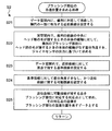
図4中に示されたステップS2の処理(ジャイロセンサ16の出力に基づいてブラッシング部位の並進位置を求める処理)について、図5の詳細なフローを用いて説明する。
図4中に示されたステップS2の処理(ジャイロセンサ16の出力に基づいてブラッシング部位の並進位置を求める処理)について、図5の詳細なフローを用いて説明する。
i) まず、図5のステップS21に示すように、制御部110がブラッシング部位検出部として働いて、図9に示すように、xy直交座標系が定められたデータ空間DS内に、歯列98U,98Lに対応して湾曲した楕円Eの一部に相当する近似曲線E1を設定する。
具体的には、歯科分野で知られているように、歯列弓は楕円の一部で近似され得る(非特許文献1)。そこで、この例では、図7(A)に示すように、「標準」的な歯列に相当するように、短径2a=71.76mm、長径2b=128.2mmを有する楕円Eのうち、奥行きD1≒50mm、幅W1≒70mmの部分を、近似曲線E1として用いる。
この例では、図9に示すように、近似曲線E1は、x軸に対して基準点としての原点O(0,0)で上に凸の態様で接するように設定される。原点O(0,0)でx軸に対して上に凸の態様で接する楕円Eは、a,bを正の係数(つまり、a>0、b>0)として、
(x/a)2+{(y+b)/b}2=1
…(Eq.1)
と表される。特に、楕円Eのうち上に凸の部分に相当する近似曲線E1については、陽関数で
y=b[{12-(x/a)2}1/2-1]
…(Eq.1′)
と表される。このようにした場合、係数a,bを定めることによって近似曲線E1を実際の歯列98U,98Lに近似した態様に設定できる。したがって、この近似曲線E1上で、ブラッシング部位の並進位置を表す対応点Pを精度良く求めることが可能になる。
(x/a)2+{(y+b)/b}2=1
…(Eq.1)
と表される。特に、楕円Eのうち上に凸の部分に相当する近似曲線E1については、陽関数で
y=b[{12-(x/a)2}1/2-1]
…(Eq.1′)
と表される。このようにした場合、係数a,bを定めることによって近似曲線E1を実際の歯列98U,98Lに近似した態様に設定できる。したがって、この近似曲線E1上で、ブラッシング部位の並進位置を表す対応点Pを精度良く求めることが可能になる。
なお、このステップS21の処理は、ステップS2の処理の度に行うのではなく、電源オン後に1回だけ実行するものとしてもよい。また、データ空間DSに近似曲線E1を設定するとは、この例では、近似曲線E1をなす点列の座標(xi,yi)(i=0,1,2,…)を記憶部115に記憶させる処理を行うことを意味する。また、近似曲線E1のデータは記憶部115に予め保存されていてもよい。
ii) 次に、図5のステップS22に示すように、制御部110がブラッシング部位検出部として働いて、図8に示すように、歯列98Uまたは98L(図8の例では、歯列98Uを示す。)が存在する実空間RS内で、歯列98Uの基準位置BP0にヘッド部4の毛210が接するときの本体1の縦軸(Y軸)Y0に対して、歯列98Uまたは98Lのブラッシング部位BPにヘッド部4の毛210が接するときの本体1の縦軸(Y軸)Y1がなす差分角度θを、ジャイロセンサ16の出力に基づいて求める。
詳しくは、この例では、既述のように、電源スイッチSをオンする時点(瞬間)では、ユーザは、歯列98Uの前面の中央である基準位置BP0にヘッド部4の毛210を当てる。その後、ユーザは、上記ブラッシング手順に従って、歯列98Uまたは98Lの別の部位(ブラッシング部位)BPにヘッド部4の毛210を当ててゆく。これにより、歯列98Uの基準位置BP0にヘッド部4の毛210が接するときの本体1の縦軸(Y軸)Y0に対して、歯列98Uまたは98Lのブラッシング部位BPにヘッド部4の毛210が接するときの本体1の縦軸(Y軸)Y1が角度(差分角度)θをなす。制御部110は、その差分角度θを、ジャイロセンサ16の出力(角速度)に基づいて求める。ここで、ジャイロセンサ16の出力は角速度であるから、一階積分すれば差分角度θを求めることができる。
なお、制御部110は、図5のステップS21の処理とステップS22の処理とを並行して行ってもよいし、ステップS21の処理よりもステップS22の処理を先に行ってもよい。
iii) 次に、図5のステップS23,S24に示すように、制御部110がブラッシング部位検出部として働いて、図9に示すように、データ空間DS内で、近似曲線E1に対して基準位置BP0に対応した原点Oで接する基準接線(この例では、x軸に相当する。)を設定するとともに、基準接線(x軸)に対して差分角度θをなし、かつ近似曲線E1に接する可動接線Qを設定する。ここで、可動接線Qは、差分角度θの変化に伴って、言い換えれば、歯列98Uまたは98Lにおけるブラッシング部位BPの変化に伴って、可変して設定される。そして、制御部110は、近似曲線E1に可動接線Qが接する点を対応点Pとして求める(図5のステップS25)。これにより、近似曲線E1上の対応点Pを、比較的簡単な処理で求めることができる。
具体的には、図9に示すように、或る可動接線Qがその近似曲線E1に点P(x1,y1)で接するものとする。その可動接線Qの方程式は、数学公式により、
xx1/a2+(y+b)(y1+b)/b2=1
…(Eq.2)
と表される。
xx1/a2+(y+b)(y1+b)/b2=1
…(Eq.2)
と表される。
また、点P(x1,y1)は楕円E上の点であるから、次式が成り立つ。
(x1/a)2+{(y1+b)/b}2=1
…(Eq.3)
(x1/a)2+{(y1+b)/b}2=1
…(Eq.3)
ここで、可動接線Qの傾きをmとすると、式(Eq.2)に基づいて、
m=-b2x1/a2(y1+b)
…(Eq.4)
と表される。
m=-b2x1/a2(y1+b)
…(Eq.4)
と表される。
式(Eq.3)と式(Eq.4)とを用いて、近似曲線E1に対する接点Pの座標x1,y1をそれぞれ傾きmで表すと、次のように表される。
x1=-a2m/{a2m2+b2}1/2
y1=-b+b2/{a2m2+b2}1/2
…(Eq.5)
x1=-a2m/{a2m2+b2}1/2
y1=-b+b2/{a2m2+b2}1/2
…(Eq.5)
さらに、可動接線Qがx軸に対してなす角度をθ(反時計回りの向きを正とし、-π/2≦θ≦π/2とする。)とし、傾きm=tanθと表すものとする。すると、式(Eq.5)は次のように表される。
x1=-a2(tanθ)/{a2(tanθ)2+b2}1/2
y1=-b+b2/{a2(tanθ)2+b2}1/2
…(Eq.6)
x1=-a2(tanθ)/{a2(tanθ)2+b2}1/2
y1=-b+b2/{a2(tanθ)2+b2}1/2
…(Eq.6)
この式(Eq.6)に従って、実空間RS内での差分角度θに基づいて、データ空間DS内で近似曲線E1上においてブラッシング部位BPに対応する対応点Pの座標(x1,y1)が求まる。この対応点Pの座標(x1,y1)をブラッシング部位BPの並進位置を表すデータとする。このようにして、ブラッシング部位BPの並進位置を解析的な式(Eq.6)で簡単に求めることができる。特に、歯列98Uの前面の中央を基準位置BP0とすることによって、式(Eq.6)は簡素化されている。なお、歯列98Lの前面の中央を基準位置BP0としてもよい。
このようにした場合、ジャイロセンサ16の出力は角速度であるから、駆動部101(モータ10)からの振動成分がノイズとして含まれ難い。また、ジャイロセンサ16の出力は角速度であるから、一階積分すれば差分角度θを求めることができ、演算過程でノイズの影響を受け難い。したがって、歯列98Uまたは98Lにおけるブラッシング部位BPの並進位置を精度良く求めることができる。
上述の式(Eq.6)に従って対応点Pの座標(x1,y1)が求まれば、そのブラッシング部位BPの並進位置が、表1に示した「左奥歯」、「前歯」、「右奥歯」のいずれの区分に属するかが決定される。
例えば、実空間RS内での差分角度θ=60°であり、それに伴ってデータ空間DSでの対応点Pの座標(x1,y1)≒(-25.0,-18.1)(単位mm)であれば、ブラッシング部位BPの並進位置は「左奥歯」の区分に属する。実空間RS内での差分角度θ=45°であり、それに伴ってデータ空間DSでの対応点Pの座標(x1,y1)≒(-17.5,-8.2)(単位mm)であれば、ブラッシング部位BPの並進位置は「前歯」の区分に属する。実空間RS内での差分角度θ=-60°であり、それに伴ってデータ空間DSでの対応点Pの座標(x1,y1)≒(25.0,-18.1)(単位mm)であれば、ブラッシング部位BPの並進位置は「右奥歯」の区分に属する。
(前面、後面、噛み合わせ面のうちいずれがブラッシングされているかの判定)
次に、図4中に示されたステップS3の処理(加速度センサ15の出力に基づいて、本体1の縦軸(Y軸)の周りでヘッド部4の毛210が向いている向き(+Z方向)を求め、そのヘッド部4の毛210が向いている向き(+Z方向)に応じて、歯列98Uまたは98Lの前面、後面、噛み合わせ面のうちいずれがブラッシングされているかを判定する処理)について、図6および図10~図15を用いて詳細に説明する。
次に、図4中に示されたステップS3の処理(加速度センサ15の出力に基づいて、本体1の縦軸(Y軸)の周りでヘッド部4の毛210が向いている向き(+Z方向)を求め、そのヘッド部4の毛210が向いている向き(+Z方向)に応じて、歯列98Uまたは98Lの前面、後面、噛み合わせ面のうちいずれがブラッシングされているかを判定する処理)について、図6および図10~図15を用いて詳細に説明する。
図6によって説明したブラッシング手順では、上顎の歯列98Uにおいて部位SQ1からSQ8まで、続いて、下顎の歯列98LにおいてSQ9からSQ16まで、数字が次第に大きくなる順序でブラッシングしてゆくものとした。さらに、そのブラッシング手順では、各部位SQ1~SQ16のブラッシング時に、図6中にそれぞれ(HL)または(HR)と括弧書きで付記しているように、本体1の縦軸(Y軸)が水平な姿勢をとった状態で、ユーザの顔に対してヘッド部4(+Y方向)が左向きと右向きのいずれに配されるかが設定されているものとする。符号HLは、図11に示すように、ユーザの顔に対してヘッド部4(+Y方向)が左向きに配されることを表している。一方、符号HRは、図12に示すように、ユーザの顔に対してヘッド部4(+Y方向)が右向きに配されることを表している。図6から分かるように、「左奥歯」として区分されている部位SQ1,SQ7,SQ8,SQ9,SQ15,SQ16のブラッシング時には、ヘッド部4(+Y方向)が左向きHLに配されることが設定されている。一方、「右奥歯」として区分されている部位SQ3,SQ4,SQ5,SQ11,SQ12,SQ13のブラッシング時には、ヘッド部4(+Y方向)が右向きHRに配されることが設定されている。これらの設定は、それぞれ「左奥歯」、「右奥歯」のブラッシングの際に必然的に要請されるものである。また、「前歯」として区分されている部位SQ2,SQ6,SQ10,SQ14のブラッシング時には、この例では、それぞれの直前の部位のブラッシングの際におけるのと同じ向きに設定されている。すなわち、部位SQ2,SQ10のブラッシング時には、ヘッド部4(+Y方向)が左向きHLに配されることが設定されている。また、部位SQ6,SQ14のブラッシング時には、ヘッド部4(+Y方向)が右向きHRに配されることが設定されている。
図10は、本体1の縦軸(Y軸)が水平な姿勢をとった状態で、ヘッド部4の側(+Y方向)から見たときに、加速度センサ15が出力する重力加速度Gの向きを示している。この図10から分かるように、加速度センサ15が出力する重力加速度Gの向きに基づいて、本体1の縦軸(Y軸)の周りでヘッド部4の毛210が向いている向き(+Z方向)が縦軸の周りの回転角φとして表される。この例では、縦軸の周りの回転角φは、鉛直下方を0°とし、図10のように本体1の縦軸(Y軸)が水平な姿勢をとった状態で、ヘッド部4の側(+Y方向)から見たときに、反時計回りに0°~359.99°(小数点以下2桁までとする。)の範囲内の値をとるものとする。
図13(A)~図13(C)は、上顎の歯列98Uの「左奥歯」の前面、後面、噛み合わせ面のうちいずれがブラッシングされているかを判定するための区分を示している。本体1の縦軸(Y軸)が水平な姿勢をとり、ユーザの顔に対してヘッド部4(+Y方向)が左向きHLに配された状態で、図13(A)に示すように、縦軸の周りの回転角φが90°~135°の範囲内にあれば、前面(したがって、左頬側部位)SQ1がブラッシングされていると判定される。その状態で、図13(B)に示すように、縦軸の周りの回転角φが135°~225°の範囲内にあれば、噛み合わせ面(したがって、左噛み合わせ面部位)SQ8がブラッシングされていると判定される。その状態で、図13(C)に示すように、縦軸の周りの回転角φが225°~270°の範囲内にあれば、後面(したがって、左舌側部位)SQ7がブラッシングされていると判定される。
同様に、図13(D)~図13(F)は、下顎の歯列98Lの「左奥歯」の前面、後面、噛み合わせ面のうちいずれがブラッシングされているかを判定するための区分を示している。本体1の縦軸(Y軸)が水平な姿勢をとり、ユーザの顔に対してヘッド部4(+Y方向)が左向きHLに配された状態で、図13(D)に示すように、縦軸の周りの回転角φが45°~90°の範囲内にあれば、前面(したがって、左頬側部位)SQ9がブラッシングされていると判定される。その状態で、図13(E)に示すように、縦軸の周りの回転角φが0°~45°または315°~359.99°の範囲内にあれば、噛み合わせ面(したがって、左噛み合わせ面部位)SQ16がブラッシングされていると判定される。その状態で、図13(F)に示すように、縦軸の周りの回転角φが270°~315°の範囲内にあれば、後面(したがって、左舌側部位)SQ15がブラッシングされていると判定される。
図14(A)~図14(B)は、上顎の歯列98Uの「前歯」の前面、後面のうちいずれがブラッシングされているかを判定するための区分を示している。本体1の縦軸(Y軸)が水平な姿勢をとり、ユーザの顔に対してヘッド部4(+Y方向)が左向きHLに配された状態で、図14(A)に示すように、縦軸の周りの回転角φが90°~180°の範囲内にあれば、前面(したがって、前唇側部位)SQ2がブラッシングされていると判定される。なお、その状態で、ブラッシング手順から外れて、縦軸の周りの回転角φが180°~270°の範囲内にあれば、後面(したがって、前舌側部位)SQ6がブラッシングされていると判定される。一方、本体1の縦軸(Y軸)が水平な姿勢をとり、ユーザの顔に対してヘッド部4(+Y方向)が右向きHRに配された状態で、図14(B)に示すように、縦軸の周りの回転角φが90°~180°の範囲内にあれば、後面(したがって、前舌側部位)SQ6がブラッシングされていると判定される。なお、その状態で、ブラッシング手順から外れて、縦軸の周りの回転角φが180°~270°の範囲内にあれば、前面(したがって、前唇側部位)SQ2がブラッシングされていると判定される。
同様に、図14(C)~図14(D)は、下顎の歯列98Lの「前歯」の前面、後面のうちいずれがブラッシングされているかを判定するための区分を示している。本体1の縦軸(Y軸)が水平な姿勢をとり、ユーザの顔に対してヘッド部4(+Y方向)が左向きHLに配された状態で、図14(C)に示すように、縦軸の周りの回転角φが0°~90°の範囲内にあれば、前面(したがって、前唇側部位)SQ10がブラッシングされていると判定される。なお、その状態で、ブラッシング手順から外れて、縦軸の周りの回転角φが270°~359.99°の範囲内にあれば、後面(したがって、前舌側部位)SQ14がブラッシングされていると判定される。一方、本体1の縦軸(Y軸)が水平な姿勢をとり、ユーザの顔に対してヘッド部4(+Y方向)が右向きHRに配された状態で、図14(D)に示すように、縦軸の周りの回転角φが0°~90°の範囲内にあれば、後面(したがって、前舌側部位)SQ14がブラッシングされていると判定される。なお、その状態で、ブラッシング手順から外れて、縦軸の周りの回転角φが270°~359.99°の範囲内にあれば、前面(したがって、前唇側部位)SQ10がブラッシングされていると判定される。
図15(A)~図15(C)は、上顎の歯列98Uの「右奥歯」の前面、後面、噛み合わせ面のうちいずれがブラッシングされているかを判定するための区分を示している。本体1の縦軸(Y軸)が水平な姿勢をとり、ユーザの顔に対してヘッド部4(+Y方向)が右向きHRに配された状態で、図15(A)に示すように、縦軸の周りの回転角φが90°~135°の範囲内にあれば、後面(したがって、右舌側部位)SQ5がブラッシングされていると判定される。その状態で、図15(B)に示すように、縦軸の周りの回転角φが135°~225°の範囲内にあれば、噛み合わせ面(したがって、右噛み合わせ面部位)SQ4がブラッシングされていると判定される。その状態で、図15(C)に示すように、縦軸の周りの回転角φが225°~270°の範囲内にあれば、前面(したがって、右頬側部位)SQ3がブラッシングされていると判定される。
同様に、図15(D)~図15(F)は、下顎の歯列98Lの「右奥歯」の前面、後面、噛み合わせ面のうちいずれがブラッシングされているかを判定するための区分を示している。本体1の縦軸(Y軸)が水平な姿勢をとり、ユーザの顔に対してヘッド部4(+Y方向)が右向きHRに配された状態で、図15(D)に示すように、縦軸の周りの回転角φが45°~90°の範囲内にあれば、後面(したがって、右舌側部位)SQ13がブラッシングされていると判定される。その状態で、図15(E)に示すように、縦軸の周りの回転角φが0°~45°または315°~359.99°の範囲内にあれば、噛み合わせ面(したがって、右噛み合わせ面部位)SQ12がブラッシングされていると判定される。その状態で、図15(F)に示すように、縦軸の周りの回転角φが270°~315°の範囲内にあれば、前面(したがって、右頬側部位)SQ11がブラッシングされていると判定される。
まとめると、縦軸の周りの回転角φと前面、後面、噛み合わせ面との対応関係は、次の表2のようになる。ここで、表2の表体は、ヘッド部4(+Y方向)が左向きHLまたは右向きHRに配された場合における、縦軸の周りの回転角φを示している。表2の表側は、縦軸の周りの回転角φに対応した、上顎の歯列98Uまたは下顎の歯列98Lの「左奥歯」の前面、噛み合わせ面、後面、「前歯」の前面、後面、「右奥歯」の前面、噛み合わせ面、後面をそれぞれ示している。なお、表2の表体における符号「-」は、ブラッシングが起こり得ないことを示している。括弧()内の回転角φは、ブラッシングが起こり得るが、既述のブラッシング手順から外れていることを示している。
(表2)縦軸の周りの回転角φと前面、後面、噛み合わせ面との対応関係
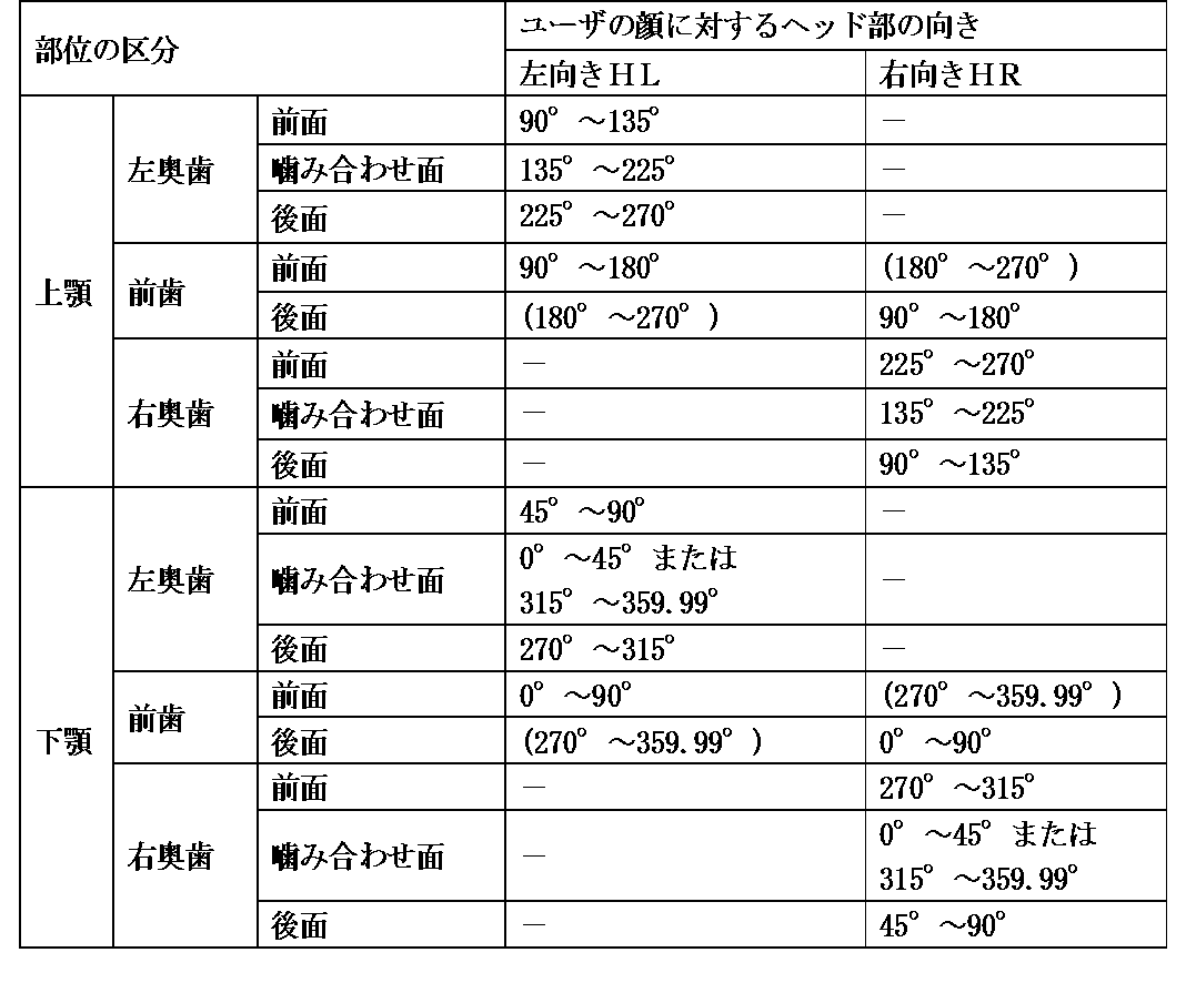
(表2)縦軸の周りの回転角φと前面、後面、噛み合わせ面との対応関係
表2に示すように、ヘッド部4の毛210が向いている向き(+Z方向)を表す縦軸の周りの回転角φに応じて、歯列98Uまたは98Lの前面、後面、噛み合わせ面のうちいずれがブラッシングされているかを判定することができる。
このように、制御部110は、加速度センサ15の出力に基づいて本体1の縦軸(Y軸)の周りでヘッド部4の毛210が向いている向き(+Z方向)を縦軸の周りの回転角φとして求め、その縦軸の周りの回転角φに応じて、歯列98Uまたは98Lの前面、後面、噛み合わせ面のうちいずれがブラッシングされているかを判定することができる。
したがって、既述のように、制御部110は、ジャイロセンサ16の出力に基づいて求められたブラッシング部位BPの並進位置と、歯列98Uまたは98Lの前面、後面、噛み合わせ面のうちいずれがブラッシングされているかの判定結果との組合せによって、歯列98Uまたは98Lにおけるブラッシング部位BPを特定することができる。これにより、歯列98Uまたは98Lにおけるブラッシング部位BPを精度良く特定することができる。
なお、左利きのユーザについては、上述のブラッシング手順全体の左右を入れ替えるのが望ましい。
(補正処理)
図6によって説明したブラッシング手順では、その図中に矢印HCG1,HCG2,HCG3,HCG4で示すように、歯列98Uまたは98Lにおいて部位SQ2から部位SQ3へ移動する際、部位SQ6から部位SQ7へ移動する際、部位SQ10から部位SQ11へ移動する際、部位SQ14から部位SQ15へ移動する際に、それぞれ、ヘッド部4の並進移動が殆ど止められた状態で、本体1の縦軸(Y軸)の向きが左向きHLから右向きHRへ、またはその逆に右向きHRから左向きHLへ、大きく変更される。また、図16に示すように、上記ブラッシング手順とは無関係に、歯磨き中のユーザが、ヘッド部4の並進移動を殆ど止めた状態で、本体1の縦軸(Y軸)の向きを、例えば矢印MV1で示すようにY2からY3へ大きく変化させる場合がある。このように、ヘッド部4の並進移動が殆ど止められた状態で、本体1の縦軸(Y軸)の向きが大きく変化される場合は、図4中に示されたステップS2の処理(ジャイロセンサ16の出力に基づいてブラッシング部位の並進位置を求める処理)において、誤差を生じる。
図6によって説明したブラッシング手順では、その図中に矢印HCG1,HCG2,HCG3,HCG4で示すように、歯列98Uまたは98Lにおいて部位SQ2から部位SQ3へ移動する際、部位SQ6から部位SQ7へ移動する際、部位SQ10から部位SQ11へ移動する際、部位SQ14から部位SQ15へ移動する際に、それぞれ、ヘッド部4の並進移動が殆ど止められた状態で、本体1の縦軸(Y軸)の向きが左向きHLから右向きHRへ、またはその逆に右向きHRから左向きHLへ、大きく変更される。また、図16に示すように、上記ブラッシング手順とは無関係に、歯磨き中のユーザが、ヘッド部4の並進移動を殆ど止めた状態で、本体1の縦軸(Y軸)の向きを、例えば矢印MV1で示すようにY2からY3へ大きく変化させる場合がある。このように、ヘッド部4の並進移動が殆ど止められた状態で、本体1の縦軸(Y軸)の向きが大きく変化される場合は、図4中に示されたステップS2の処理(ジャイロセンサ16の出力に基づいてブラッシング部位の並進位置を求める処理)において、誤差を生じる。
また、上述のブラッシング手順から外れて、例えば図17に示すように、歯磨き中のユーザが、本体1の縦軸(Y軸)の向きを殆ど変化させることなく、例えば上顎の歯列98Uにおいて矢印MV2で示すように左頬側部位SQ1から右舌側部位SQ5へ、部位を飛び越えて本体1を大きく並進移動させる場合がある。このように、本体1の縦軸(Y軸)の向きを殆ど変化させることなく、部位を飛び越えて本体1が大きく並進移動される場合は、図4中に示されたステップS2の処理(ジャイロセンサ16の出力に基づいてブラッシング部位の並進位置を求める処理)において、誤差を生じる。
そこで、この例では、制御部110は、図4におけるステップS2~S5の処理を繰り返す間に、図18のフローに示す補正処理を行う。
すなわち、制御部110は、図18のステップS41に示すように、処理単位期間としての0.1秒間毎に、加速度センサ15が出力する本体1の加速度に基づいて二階積分を行って本体1の並進移動量を算出する。ここで、本体1の3軸方向の加速度をそれぞれAcc_X,Acc_Y,Acc_Zで表し、3軸方向の速度をそれぞれv_X,v_Y,v_Zで表し、3軸方向の本体1の並進移動量をそれぞれD_X,D_Y,D_Zで表すものとする。すると、処理単位期間毎の本体1の並進移動量Di(ただし、i=1,2,3,…)は、次の式(Eq.7),(Eq.8),(Eq.9)により求められる。
v_X=∫(Acc_X)dt
v_Y=∫(Acc_Y)dt
v_Z=∫(Acc_Z)dt
…(Eq.7)
D_X=∫(v_X)dt
D_Y=∫(v_Y)dt
D_Z=∫(v_Z)dt
…(Eq.8)
Di=(D_X)+(D_Y)+(D_Z)
…(Eq.9)
v_X=∫(Acc_X)dt
v_Y=∫(Acc_Y)dt
v_Z=∫(Acc_Z)dt
…(Eq.7)
D_X=∫(v_X)dt
D_Y=∫(v_Y)dt
D_Z=∫(v_Z)dt
…(Eq.8)
Di=(D_X)+(D_Y)+(D_Z)
…(Eq.9)
次に、制御部110は、ステップS42に示すように、予め定められた集計単位期間としての0.5秒間毎に、本体1の並進移動量Diを集計する。ここで、処理単位期間毎の並進移動量Diを、それぞれD1,D2,D3,D4,D5と表すものとすると、或る集計単位期間について、トータルの並進移動量D_totalは、次の式(Eq.10)により求められる。
D_total=D1+D2+D3+D4+D5
…(Eq.10)
D_total=D1+D2+D3+D4+D5
…(Eq.10)
次に、制御部110は、ステップS43に示すように、或る集計単位期間について、トータルの並進移動量D_totalが予め定められた第1閾値α1以下であるか否かを判断する。この例では、α1=20mmに設定されている。ここで、D_total≦α1であるとき(ステップS43でYES)、ステップS44に進んで、制御部110は、その集計単位期間では、ジャイロセンサ16の出力に基づいて求められたブラッシング部位BPの並進位置を維持する(第1の補正処理)。
このようにした場合、例えば図16に示したような、歯磨き中のユーザが、本体1(特に、ヘッド部4)の並進移動を殆ど止めた状態で、本体1の縦軸(Y軸)の向きを大きく変化させたような場合に、その変化の前後で、ジャイロセンサ16の出力に基づいて求められたブラッシング部位BPの並進位置が維持される。これにより、求められたブラッシング部位BPの並進位置の精度を維持することができる。
なお、歯列の区分が表1のものよりも細かく区分された場合、例えば、歯列弓に沿って個々の歯毎に区分された場合、さらに個々の歯が左右半分ずつに区分された場合は、それに応じて、第1閾値α1の値を、例えば10mm、5mmというように、より小さく設定するのが望ましい。
一方、図18のステップS43で、トータルの並進移動量D_totalが第1閾値α1を超えていれば(ステップS43でNO)、ステップS45に進んで、制御部110は、その集計単位期間について、トータルの並進移動量D_totalが予め定められた第2閾値α2以上であるか否かを判断する。この例では、α2はα1よりも大きく、α2=30mmに設定されている。ここで、D_total≧α2であるとき(ステップS45でYES)、制御部110は、データ空間DS内の近似曲線E1上における本体1の並進移動先に相当する部分へシフトして、ジャイロセンサ16の出力に基づいて対応点Pを求め直す(第2の補正処理)。
例えば図17に示したような、本体1の縦軸(Y軸)の向きを殆ど変化させることなく、例えば上顎の歯列98Uにおいて左頬側部位SQ1から右舌側部位SQ5へ、部位を飛び越えて本体1が大きく並進移動されたような場合に、制御部110は、図9に示したデータ空間DS内の近似曲線E1上における、x座標が-a近傍の点から+a近傍の点へシフトして、ジャイロセンサ16の出力(差分角度θ)に基づいて対応点Pを求め直す。
このようにした場合、歯列98Uまたは98Lにおけるブラッシング部位BPの並進位置を精度良く求めることができる。
この例では、加速度センサ15の出力に基づいて二階積分を行って処理単位期間毎の本体1の並進移動量Diを算出している。このため、算出された本体1のトータルの並進移動量D_totalは、ノイズの影響を受けて、精度が良くないと言える。しかし、算出された本体1のトータルの並進移動量D_totalを、本体1(特に、ヘッド部4)の並進移動量が殆ど無いか(図18のステップS43)、極端に大きいか(図18のステップS45)の判定に用いることには、支障がない。
なお、α1<D_total<α2であれば(図18のステップS43でNO、かつ、図18のステップS45でNO)、制御部110は、補正の必要が無いと判断して、図4のフロー(ステップS2~S5)にリターンする。
上の例では、ブラッシング部位BPの並進位置を求めるために、図7(A)に示した楕円Eの一部である「標準」的な近似曲線E1を用いた。しかしながら、これに限られるものではない。例えば、「標準」的な歯列に比して奥行きが長く且つ幅が狭い「縦長」の歯列を有するユーザについては、図7(B)に示すように、短径2a′=60.43mm、長径2b′=136.2mmを有する楕円E′のうち、奥行きD2≒60mm、幅W2≒60mmの部分を、近似曲線E2として用いてもよい。また、「標準」的な歯列に比して「小型」の歯列を有するユーザについては、図7(C)に示すように、短径2a″=62.21mm、長径2b″=135.9mmを有する楕円E″のうち、奥行きD3≒50mm、幅W3≒60mmの部分を、近似曲線E3として用いてもよい。これらの「標準」的な近似曲線E1、「縦長」の近似曲線E2、または、「小型」の近似曲線E3の選択(短径、長径の設定を含む。)は、この例では、本体1の外部から受信部としての通信部180を通して、設定パラメータを受信することによって実行される。そのようにした場合、様々なユーザの歯列弓のサイズと形状に応じて、近似曲線を適切に設定することができる。これにより、歯列におけるブラッシング部位BPの並進位置をさらに精度良く求めることができる。
また、制御部110が取得した部位毎の実ブラッシング時間データ、その他ブラッシングに関するデータを、送信部としての通信部180を通して、本体1の外部へ送信してもよい。この場合、例えば、そのデータを本体1の外部に設けられたコンピュータ装置によって受信して、様々な処理、用途に用いることができる。
(別の近似曲線)
上述の実施形態では、実空間RSにおける被験者の歯列弓を、データ空間DSにおける楕円Eの一部に相当する曲線(近似曲線E1,E2またはE3)によって近似したが、これに限られるものではない。
上述の実施形態では、実空間RSにおける被験者の歯列弓を、データ空間DSにおける楕円Eの一部に相当する曲線(近似曲線E1,E2またはE3)によって近似したが、これに限られるものではない。
図19に示すように、実空間RSにおける被験者の歯列弓を、データ空間DSにおける放物線Uによって近似してもよい。便宜上、その放物線Uは、原点O(0,0)でx軸に対して上に凸の態様で接するものとする。
原点O(0,0)でx軸に対して上に凸の態様で接する放物線Uは、pを負の係数(つまり、p<0)として、
4py=x2 …(Eq.11)
と表される。
4py=x2 …(Eq.11)
と表される。
或る可動接線Qがその放物線Uに点P(x1,y1)で接するものとする。その可動接線Qの方程式は、数学公式により、
2p(y+y1)=xx1 …(Eq.12)
と表される。
2p(y+y1)=xx1 …(Eq.12)
と表される。
また、点P(x1,y1)は放物線U上の点であるから、次式が成り立つ。
4py1=x1 2 …(Eq.13)
4py1=x1 2 …(Eq.13)
ここで、可動接線Qの傾きをmとすると、式(Eq.12)に基づいて、
m=x1/2p …(Eq.14)
と表される。
m=x1/2p …(Eq.14)
と表される。
式(Eq.13)と式(Eq.14)とを用いて、放物線Uに対する接点Pの座標x1,y1をそれぞれ傾きmで表すと、次のように表される。
x1=2pm
y1=pm2
…(Eq.15)
x1=2pm
y1=pm2
…(Eq.15)
さらに、可動接線Qがx軸に対してなす角度をθ(反時計回りの向きを正とし、-π/2≦θ≦π/2とする。)とし、傾きm=tanθと表すものとする。すると、式(Eq.15)は次のように表される。
x1=2p(tanθ)
y1=p(tanθ)2
…(Eq.16)
x1=2p(tanθ)
y1=p(tanθ)2
…(Eq.16)
この式(Eq.16)に従って、実空間RS内での差分角度θに基づいて、データ空間DS内で放物線U上においてブラッシング部位BPに対応する対応点Pの座標(x1,y1)が求まる。
このようにした場合、係数pを定めることによって近似曲線を設定できる。したがって、対応点Pを求める処理を簡単に行うことができる。
(システム)
図20は、上述の電動歯ブラシ90とスマートフォン600とを含むシステム(全体を符号700で示す。)の構成を例示している。このシステム700は、電動歯ブラシ90と、コンピュータ装置としてのスマートフォン600とを、ネットワーク900を介して互いに無線通信可能に備えている。
図20は、上述の電動歯ブラシ90とスマートフォン600とを含むシステム(全体を符号700で示す。)の構成を例示している。このシステム700は、電動歯ブラシ90と、コンピュータ装置としてのスマートフォン600とを、ネットワーク900を介して互いに無線通信可能に備えている。
スマートフォン600は、本体600Mと、この本体600Mに搭載された、制御部610と、記憶部620と、操作部630と、表示器640と、通信部680と、電源部690とを含んでいる。このスマートフォン600は、市販のスマートフォンに、後述のアプリケーションソフトウェアをインストールしたものである。
制御部610は、CPUおよびその補助回路を含み、スマートフォン600の各部を制御し、記憶部620に記憶されたプログラムおよびデータに従って処理を実行する。例えば、操作部630を介して入力された指示に基づいて、通信部680から入力されたデータを処理し、処理したデータを、記憶部620に記憶させたり、表示器640で表示させたり、通信部680を介して出力させたりする。
記憶部620は、制御部610でプログラムを実行するために必要な作業領域として用いられるRAM(Random Access Memory)と、制御部610で実行するための基本的なプログラムを記憶するためのROM(Read Only Memory)とを含む。また、記憶部620の記憶領域を補助するための補助記憶装置の記憶媒体として、半導体メモリ(メモリカード、SSD(Solid State Drive))などが用いられてもよい。
操作部630は、この例では、表示器640上に設けられたタッチパネルからなっている。なお、キーボードその他のハードウェア操作デバイスを含んでいても良い。
表示器640は、この例ではLCD(液晶表示素子)または有機EL(エレクトロルミネッセンス)ディスプレイからなる表示画面を含む。表示器640は、制御部610による制御に従って、様々な画像を表示画面に表示させる。
通信部680は、制御部610による制御に従って、ネットワーク900を介して、電動歯ブラシ90との間で無線通信(例えば、BT通信、BLE通信など)可能に構成されている。
電源部690は、この例では充電池を含み、このスマートフォン600の各部へ電力を供給する。
ユーザは、スマートフォン600に予め、アプリケーションソフトウェア(これを「電動歯ブラシプログラム」と呼ぶ。)をインストールしておくものとする。この電動歯ブラシプログラムは、電動歯ブラシ90との間で無線通信を行って、電動歯ブラシ90にブラッシング手順等に関する各種設定を行ったり、電動歯ブラシ90からブラッシング部位BPを特定するデータや、ブラッシング部位の並進位置(座標値)、ヘッド部4の毛210が向いている向き、ジャイロセンサや加速度センサの出力値等を受信して様々な処理に用いたりするプログラムである。
(近似曲線の設定)
例えば、ユーザがこの電動歯ブラシプログラムを起動させ、操作部630を介して「電動歯ブラシ設定」モードを選択するものとする。すると、表示器640に「近似曲線設定」画面が表示され、「標準」的な近似曲線E1(短径2a=71.76mm、長径2b=128.2mmを有する楕円Eのうち、奥行きD1≒50mm、幅W1≒70mmの部分)と、「縦長」の近似曲線E2(短径2a′=60.43mm、長径2b′=136.2mmを有する楕円E′のうち、奥行きD2≒60mm、幅W2≒60mmの部分)と、「小型」の近似曲線E3(短径2a″=62.21mm、長径2b″=135.9mmを有する楕円E″のうち、奥行きD3≒50mm、幅W3≒60mmの部分)とが、選択候補として表示される。ユーザが操作部630を介してそれらの選択候補のうちのいずれかを選択すると、電動歯ブラシ90に、その選択された近似曲線が設定される。
例えば、ユーザがこの電動歯ブラシプログラムを起動させ、操作部630を介して「電動歯ブラシ設定」モードを選択するものとする。すると、表示器640に「近似曲線設定」画面が表示され、「標準」的な近似曲線E1(短径2a=71.76mm、長径2b=128.2mmを有する楕円Eのうち、奥行きD1≒50mm、幅W1≒70mmの部分)と、「縦長」の近似曲線E2(短径2a′=60.43mm、長径2b′=136.2mmを有する楕円E′のうち、奥行きD2≒60mm、幅W2≒60mmの部分)と、「小型」の近似曲線E3(短径2a″=62.21mm、長径2b″=135.9mmを有する楕円E″のうち、奥行きD3≒50mm、幅W3≒60mmの部分)とが、選択候補として表示される。ユーザが操作部630を介してそれらの選択候補のうちのいずれかを選択すると、電動歯ブラシ90に、その選択された近似曲線が設定される。
なお、選択される楕円の短径、長径、および、選択される楕円のうち近似曲線として用いられる部分の寸法(奥行き、幅)は、表示器640の画面上で、連続値で可変して設定可能になっていてもよい。
また、近似曲線として放物線Uを用いる場合は、その係数pを可変して設定するのが望ましい。
(ブラッシングの評価)
図6によって説明したブラッシング手順では、上顎の歯列98Uにおいて部位SQ1からSQ8まで、続いて、下顎の歯列98Lにおいて部位SQ9からSQ16まで、数字が次第に大きくなる順序でブラッシングしてゆくものとした。さらに、そのブラッシング手順では、次の表3に例示するように、各部位SQ1~SQ16のブラッシング時に、それぞれ各部位SQ1~SQ16毎に予め定められたブラッシング設定期間だけブラッシングしてゆくことが設定されているものとする。例えば、ブラッシング設定期間は、上顎の歯列98Uにおいて部位SQ1については8秒間、部位SQ2については4秒間、部位SQ3については9秒間、…というように設定されている。また、下顎の歯列98Lにおいて部位SQ9については5秒間、部位SQ10については5秒間、部位SQ11については7秒間、…というように設定されている。
(表3)

図6によって説明したブラッシング手順では、上顎の歯列98Uにおいて部位SQ1からSQ8まで、続いて、下顎の歯列98Lにおいて部位SQ9からSQ16まで、数字が次第に大きくなる順序でブラッシングしてゆくものとした。さらに、そのブラッシング手順では、次の表3に例示するように、各部位SQ1~SQ16のブラッシング時に、それぞれ各部位SQ1~SQ16毎に予め定められたブラッシング設定期間だけブラッシングしてゆくことが設定されているものとする。例えば、ブラッシング設定期間は、上顎の歯列98Uにおいて部位SQ1については8秒間、部位SQ2については4秒間、部位SQ3については9秒間、…というように設定されている。また、下顎の歯列98Lにおいて部位SQ9については5秒間、部位SQ10については5秒間、部位SQ11については7秒間、…というように設定されている。
(表3)
図4のステップS8に関して述べたように、特定されたブラッシング部位BPとその部位BPについての実際のブラッシング時間とが対応付けられて、記憶部115に用意されたテーブルに部位毎の実ブラッシング時間データとして記録されている。この例では、表3中に示すように、実際のブラッシング時間は、上顎の歯列98Uにおいて部位SQ1については7.2秒間、部位SQ2については3.7秒間、部位SQ3については6.9秒間、…という値であった。また、下顎の歯列98Lおいて部位SQ9については5秒間、部位SQ10については4.6秒間、部位SQ11については6.6秒間、…という値であった。
この例では、スマートフォン600の制御部610が、通信部680を介して電動歯ブラシ90から記憶部115のテーブルに記録されたデータ(部位毎の実ブラッシング時間データを含む。)を受信する。制御部610は、ブラッシング評価部として働いて、上記部位毎の実ブラッシング時間データに基づいて、上記ブラッシング手順に対する一致の程度を表す評価値(ブラッシング評価値)を算出する。
具体的には、各部位SQ1~SQ16毎に、ブラッシング評価値(単位%)を次式により算出する。
(ブラッシング評価値)=100×(実際のブラッシング時間(sec))/(ブラッシング設定期間(sec))
(ブラッシング評価値)=100×(実際のブラッシング時間(sec))/(ブラッシング設定期間(sec))
表3のデータの例では、ブラッシング評価値は、上顎の歯列98Uにおいて部位SQ1については90%、部位SQ2については93%、部位SQ3については77%、…という値になる。また、下顎の歯列98Lおいて部位SQ9については100%、部位SQ10については92%、部位SQ11については94%、…という値になる。
この例では、スマートフォン600の制御部610は、表示器640の表示画面に、これらのブラッシング評価値を表示させる。それにより、ユーザは表示器640の表示画面を見て、上記ブラッシング手順に対する自身のブラッシングの仕方の一致または不一致の程度を知ることができる。特に、上記ブラッシング手順に対する自身のブラッシングの不一致の傾向、例えば、上顎の歯列98Uにおいて左奥歯の後面(部位SQ7)と右奥歯の後面(部位SQ5)が特にブラッシング不足となる傾向など、を知ることができる。したがって、ユーザは自身のブラッシングの仕方を改善できる。
上述の実施形態では、電動歯ブラシ90の制御部110がブラッシング部位検出部の機能を実行したが、これに限られるものではない。歯磨き中に電動歯ブラシ90とスマートフォン600との間で通信を行いながら、スマートフォン600の制御部610がブラッシング部位検出部の機能の一部または全部を実行してもよい。そのようにした場合、電動歯ブラシ90の制御部110の構成を簡素化できる。これにより、制御部110を、CPUに代えて、例えばロジックIC(集積回路)によって構成することが可能になる。
例えば、電動歯ブラシ90の制御部110がブラッシング部位検出部の機能のうちブラッシング部位BPの基本的な特定(図4のフロー、特にステップS2,S3)を行う一方、スマートフォン600の制御部610が補正処理(図18のフロー)を行ってもよい。これにより、電動歯ブラシ90とスマートフォン600との間で処理負荷を分散できる。
電動歯ブラシ90と組み合わされたシステムを構成するために、スマートフォン600に代えて、タブレット端末、パーソナルコンピュータなど、実質的にコンピュータ装置として機能する装置を用いてもよい。
また、上述の電動歯ブラシ90の制御部110またはスマートフォン600の制御部610が実行する処理の方法は、アプリケーションソフトウェア(コンピュータプログラム)として、CD(コンパクトディスク)、DVD(デジタル万能ディスク)、フラッシュメモリなどの非一時的(non-transitory)にデータを記憶可能な記録媒体に記録され得る。このような記録媒体に記録されたアプリケーションソフトウェアを、パーソナルコンピュータ、PDA(パーソナル・デジタル・アシスタンツ)、スマートフォンなどの実質的なコンピュータ装置にインストールすることによって、それらのコンピュータ装置に、上述の方法を実行させることができる。
なお、ユーザの歯列弓が水平面に対して傾斜している場合は、データ空間にxyz直交座標系を設定し、水平なxy平面に対して傾斜した近似曲線を設定してもよい。これにより、そのようなユーザの歯列弓を近似曲線で精度良く近似できる。したがって、歯列におけるブラッシング部位の並進位置を精度良く求めることができる。
以上の実施形態は例示であり、この発明の範囲から離れることなく様々な変形が可能である。上述した複数の実施の形態は、それぞれ単独で成立し得るものであるが、実施の形態同士の組みあわせも可能である。また、異なる実施の形態の中の種々の特徴も、それぞれ単独で成立し得るものであるが、異なる実施の形態の中の特徴同士の組みあわせも可能である。
1,600M 本体
3 ネック部
4 ヘッド部
5 グリップ部
15 加速度センサ
16 ジャイロセンサ
90 電動歯ブラシ
110,610 制御部
210 毛
600 スマートフォン
640 表示器
700 システム
3 ネック部
4 ヘッド部
5 グリップ部
15 加速度センサ
16 ジャイロセンサ
90 電動歯ブラシ
110,610 制御部
210 毛
600 スマートフォン
640 表示器
700 システム
Claims (15)
- 毛が立設された起毛面を有するヘッド部、手で握られるべきグリップ部、および、上記ヘッド部と上記グリップ部とを連結するネック部を、縦軸方向に沿って有する本体と、
上記本体の内部に搭載され、上記本体の角速度を検知するジャイロセンサと、
上記ジャイロセンサの出力に基づいて、歯列におけるブラッシング部位の並進位置を求めるブラッシング部位検出部とを備え、
上記ブラッシング部位検出部は、
上記歯列の基準位置に上記ヘッド部の毛が接するときの上記本体の縦軸に対して、上記歯列のブラッシング部位に上記ヘッド部の毛が接するときの上記本体の縦軸がなす角度を、上記ジャイロセンサの出力に基づいて求め、
上記角度に基づいて、上記歯列に対応して湾曲した近似曲線上において上記ブラッシング部位に対応する対応点を求めて、その対応点の座標を上記ブラッシング部位の並進位置とすることを特徴とする電動歯ブラシ。 - 請求項1に記載の電動歯ブラシにおいて、
上記ブラッシング部位検出部は、上記近似曲線に対して上記基準位置に対応した基準点で接する基準接線を設定するとともに、上記基準接線に対して上記角度をなし、かつ上記近似曲線に接する可動接線を設定し、上記近似曲線に上記可動接線が接する点を上記対応点として求めることを特徴とする電動歯ブラシ。 - 請求項1または2に記載の電動歯ブラシにおいて、
上記歯列の基準位置は、上記歯列の前面の中央であることを特徴とする電動歯ブラシ。 - 請求項1から3までのいずれか一つに記載の電動歯ブラシにおいて、
上記ブラッシング部位検出部は、xy直交座標系が定められたデータ空間内に、上記近似曲線を、正の係数aおよびbを用いて、関数y=b[{1-(x/a)2}1/2-1]で表される楕円の一部に相当する曲線として設定することを特徴とする電動歯ブラシ。 - 請求項1から3までのいずれか一つに記載の電動歯ブラシにおいて、
上記ブラッシング部位検出部は、xy直交座標系が定められたデータ空間内に、上記近似曲線を、負の係数pを用いて、関数4py=x2で表される放物線として設定することを特徴とする電動歯ブラシ。 - 請求項4または5に記載の電動歯ブラシにおいて、
上記本体の外部から設定パラメータを受信可能な受信部を備え、
上記ブラッシング部位検出部は、上記受信部を通して受信した設定パラメータに応じて、上記係数aおよびbまたは上記係数pを可変して設定可能になっていることを特徴とする電動歯ブラシ。 - 請求項1から6までのいずれか一つに記載の電動歯ブラシにおいて、
上記本体の内部に搭載された加速度センサを備え、
上記ブラッシング部位検出部は、上記ジャイロセンサの出力と上記加速度センサの出力に基づいて、上記歯列におけるブラッシング部位を特定することを特徴とする電動歯ブラシ。 - 請求項7に記載の電動歯ブラシにおいて、
上記ブラッシング部位検出部は、
上記加速度センサが出力する重力加速度の向きに基づいて上記本体の縦軸の周りで上記ヘッド部の毛が向いている向きを求め、上記ヘッド部の毛が向いている向きに応じて上記歯列の前面、後面、噛み合わせ面のうちいずれがブラッシングされているかを判定し、
上記ジャイロセンサの出力に基づいて求められた上記ブラッシング部位の並進位置と、上記歯列の前面、後面、噛み合わせ面のうちいずれがブラッシングされているかの判定結果との組合せによって、上記歯列におけるブラッシング部位を特定することを特徴とする電動歯ブラシ。 - 請求項7または8に記載の電動歯ブラシにおいて、
上記ブラッシング部位検出部は、
予め定められた集計単位期間毎に、上記加速度センサが出力する上記本体の加速度に基づいて上記本体の並進移動量を算出し、
或る集計単位期間について、上記本体の並進移動量が予め定められた第1閾値以下であるとき、その集計単位期間では、上記ジャイロセンサの出力に基づいて求められた上記ブラッシング部位の並進位置を維持する第1の補正処理を行うことを特徴とする電動歯ブラシ。 - 請求項7または8に記載の電動歯ブラシにおいて、
上記ブラッシング部位検出部は、
予め定められた集計単位期間毎に、上記加速度センサが出力する上記本体の加速度に基づいて上記本体の並進移動量を算出し、
上記本体の並進移動量が予め定められた第2閾値以上であるとき、上記近似曲線上における上記本体の並進移動先に相当する部分へシフトして、上記ジャイロセンサの出力に基づいて上記対応点を求め直す第2の補正処理を行うことを特徴とする電動歯ブラシ。 - 請求項1から10までのいずれか一つに記載の電動歯ブラシにおいて、
ブラッシングに関するデータを、上記本体の外部へ送信可能な送信部を備えたことを特徴とする電動歯ブラシ。 - 請求項11に記載の電動歯ブラシと、この電動歯ブラシの本体の外部に設けられたコンピュータ装置とを、互いに通信可能に含むシステム。
- 請求項12に記載のシステムにおいて、
上記歯列における複数の部位を予め定められた順序で、かつ、それぞれ予め定められたブラッシング設定期間だけブラッシングしてゆくブラッシング手順が定められており、
上記ブラッシング部位検出部によって特定されたブラッシング部位に基づいて、上記ブラッシング手順に対する一致の程度を表す評価値を算出するブラッシング評価部を備えたことを特徴とするシステム。 - 歯列において電動歯ブラシによってブラッシングされるブラッシング部位を検出するブラッシング部位検出方法であって、
上記電動歯ブラシは、
毛が立設された起毛面を有するヘッド部、手で握られるべきグリップ部、および、上記ヘッド部と上記グリップ部とを連結するネック部を、縦軸方向に沿って有する本体と、
上記本体の内部に搭載され、上記本体の角速度を検知するジャイロセンサとを備え、
上記ブラッシング部位検出方法は、
上記歯列が存在する実空間内で、上記歯列の基準位置に対して上記ヘッド部の毛が接するときの上記本体の縦軸に対して、上記歯列のブラッシング部位に対して上記ヘッド部の毛が接するときの上記本体の縦軸がなす差分角度を、上記ジャイロセンサの出力に基づいて求め、
上記実空間内での上記差分角度に基づいて、データ空間内に設定された上記歯列に対応して湾曲した近似曲線上において上記ブラッシング部位に対応する対応点を求めて、その対応点の座標を上記ブラッシング部位の並進位置を表すデータとすることを特徴とするブラッシング部位検出方法。 - 請求項14に記載のブラッシング部位検出方法をコンピュータに実行させるためのプログラム。
Priority Applications (3)
| Application Number | Priority Date | Filing Date | Title |
|---|---|---|---|
| DE112018003570.0T DE112018003570B4 (de) | 2017-07-11 | 2018-06-08 | Elektrische zahnbürste, system, bürststellenerfassungsverfahren und programm |
| CN201880030390.3A CN110612044B (zh) | 2017-07-11 | 2018-06-08 | 电动牙刷、系统、刷牙部位检测方法和存储介质 |
| US16/693,571 US11484113B2 (en) | 2017-07-11 | 2019-11-25 | Electric toothbrush, system, brushing site detection method, and computer-readable recording medium |
Applications Claiming Priority (2)
| Application Number | Priority Date | Filing Date | Title |
|---|---|---|---|
| JP2017-135687 | 2017-07-11 | ||
| JP2017135687A JP6953845B2 (ja) | 2017-07-11 | 2017-07-11 | 電動歯ブラシ、システム、ブラッシング部位検出方法およびプログラム |
Related Child Applications (1)
| Application Number | Title | Priority Date | Filing Date |
|---|---|---|---|
| US16/693,571 Continuation US11484113B2 (en) | 2017-07-11 | 2019-11-25 | Electric toothbrush, system, brushing site detection method, and computer-readable recording medium |
Publications (1)
| Publication Number | Publication Date |
|---|---|
| WO2019012879A1 true WO2019012879A1 (ja) | 2019-01-17 |
Family
ID=65001160
Family Applications (1)
| Application Number | Title | Priority Date | Filing Date |
|---|---|---|---|
| PCT/JP2018/021986 Ceased WO2019012879A1 (ja) | 2017-07-11 | 2018-06-08 | 電動歯ブラシ、システム、ブラッシング部位検出方法およびプログラム |
Country Status (5)
| Country | Link |
|---|---|
| US (1) | US11484113B2 (ja) |
| JP (1) | JP6953845B2 (ja) |
| CN (1) | CN110612044B (ja) |
| DE (1) | DE112018003570B4 (ja) |
| WO (1) | WO2019012879A1 (ja) |
Cited By (1)
| Publication number | Priority date | Publication date | Assignee | Title |
|---|---|---|---|---|
| US11346938B2 (en) | 2019-03-15 | 2022-05-31 | Msa Technology, Llc | Safety device for providing output to an individual associated with a hazardous environment |
Families Citing this family (4)
| Publication number | Priority date | Publication date | Assignee | Title |
|---|---|---|---|---|
| DE102018216586A1 (de) | 2018-09-27 | 2020-04-02 | Siemens Aktiengesellschaft | Verblockungselement für Rotorwickelköpfe bei Turbogeneratoren mit Läuferkappe mit radialen Ventilationsbohrungen |
| JP7262084B2 (ja) * | 2020-02-07 | 2023-04-21 | パナソニックIpマネジメント株式会社 | 電動歯ブラシ |
| CN114577259A (zh) * | 2022-02-08 | 2022-06-03 | 深圳市云顶信息技术有限公司 | 一种刷牙信息反馈方法、装置、电子设备和存储介质 |
| CN115006035B (zh) * | 2022-05-30 | 2023-06-27 | 深圳市新博电科技开发有限公司 | 一种电动牙刷控制方法 |
Citations (2)
| Publication number | Priority date | Publication date | Assignee | Title |
|---|---|---|---|---|
| JP2016532492A (ja) * | 2013-08-11 | 2016-10-20 | 王勇競 | オーラルケアシステム及び方法 |
| JP2017060662A (ja) * | 2015-09-25 | 2017-03-30 | サンスター株式会社 | 歯ブラシモジュール、及び歯磨支援システム |
Family Cites Families (4)
| Publication number | Priority date | Publication date | Assignee | Title |
|---|---|---|---|---|
| JP5293101B2 (ja) | 2008-03-14 | 2013-09-18 | オムロンヘルスケア株式会社 | 電動歯ブラシ |
| FI20085488A0 (fi) * | 2008-05-23 | 2008-05-23 | Pump & Brush Finland Oy | Älykäs hammasharjamonitorointilaite |
| CN105029891B (zh) | 2015-08-19 | 2017-08-29 | 秦立新 | 刷牙动作检测校正方法及系统、牙刷、远程控制装置 |
| CN105466422A (zh) * | 2015-12-02 | 2016-04-06 | 爱芽(北京)科技有限公司 | 一种检测牙刷在口腔内部位置变动算法 |
-
2017
- 2017-07-11 JP JP2017135687A patent/JP6953845B2/ja active Active
-
2018
- 2018-06-08 DE DE112018003570.0T patent/DE112018003570B4/de active Active
- 2018-06-08 WO PCT/JP2018/021986 patent/WO2019012879A1/ja not_active Ceased
- 2018-06-08 CN CN201880030390.3A patent/CN110612044B/zh active Active
-
2019
- 2019-11-25 US US16/693,571 patent/US11484113B2/en active Active
Patent Citations (2)
| Publication number | Priority date | Publication date | Assignee | Title |
|---|---|---|---|---|
| JP2016532492A (ja) * | 2013-08-11 | 2016-10-20 | 王勇競 | オーラルケアシステム及び方法 |
| JP2017060662A (ja) * | 2015-09-25 | 2017-03-30 | サンスター株式会社 | 歯ブラシモジュール、及び歯磨支援システム |
Non-Patent Citations (1)
| Title |
|---|
| SAKA, TSUTOMU: "The studies on the factor analysis of the morphologic variation of the palatal vault. In relation to the maxillo-facial-cranial pattern", JAPANESE JOURNAL OF ORAL & MAXILLOFACIAL SURGERY, vol. 34, 3 March 1988 (1988-03-03), pages 451 - 469, XP055566988 * |
Cited By (2)
| Publication number | Priority date | Publication date | Assignee | Title |
|---|---|---|---|---|
| US11346938B2 (en) | 2019-03-15 | 2022-05-31 | Msa Technology, Llc | Safety device for providing output to an individual associated with a hazardous environment |
| US12169234B2 (en) | 2019-03-15 | 2024-12-17 | Msa Technology, Llc | Safety device for providing output to an individual associated with a hazardous environment |
Also Published As
| Publication number | Publication date |
|---|---|
| DE112018003570T5 (de) | 2020-03-26 |
| CN110612044A (zh) | 2019-12-24 |
| US11484113B2 (en) | 2022-11-01 |
| CN110612044B (zh) | 2021-06-22 |
| JP2019017418A (ja) | 2019-02-07 |
| US20200093253A1 (en) | 2020-03-26 |
| DE112018003570B4 (de) | 2025-02-06 |
| JP6953845B2 (ja) | 2021-10-27 |
Similar Documents
| Publication | Publication Date | Title |
|---|---|---|
| WO2019012879A1 (ja) | 電動歯ブラシ、システム、ブラッシング部位検出方法およびプログラム | |
| CN103764063B (zh) | 用于去除牙齿牙垢的口腔护理装置 | |
| JP5482209B2 (ja) | 電動歯ブラシ | |
| JP2019017418A5 (ja) | ||
| KR101574129B1 (ko) | 지능형 칫솔 모니터링 장치 | |
| CN109788845B (zh) | 智能牙刷 | |
| US8341791B2 (en) | Electric toothbrush | |
| US10779924B2 (en) | Electric toothbrush device and method | |
| JP5359210B2 (ja) | 電動歯ブラシ | |
| EP3522752B1 (en) | Smart toothbrush | |
| JP2019508183A (ja) | コンプライアンスの監視のための、視覚的認識を伴う口腔衛生システム | |
| JP6914939B2 (ja) | ブラッシングセッションのフィードバックを提供するための方法及びシステム | |
| CN109862807B (zh) | 智能牙刷 | |
| US20200022488A1 (en) | Method for determining the orientation of a user's head during teeth cleaning | |
| JP2021122609A (ja) | 歯ブラシシステム、および歯ブラシシステム用プログラム | |
| TWI744048B (zh) | 刷牙系統及刷牙方法 | |
| JP2016106751A (ja) | 歯ブラシおよび歯磨き管理システム |
Legal Events
| Date | Code | Title | Description |
|---|---|---|---|
| 121 | Ep: the epo has been informed by wipo that ep was designated in this application |
Ref document number: 18832736 Country of ref document: EP Kind code of ref document: A1 |
|
| DPE2 | Request for preliminary examination filed before expiration of 19th month from priority date (pct application filed from 20040101) | ||
| WWP | Wipo information: published in national office |
Ref document number: 112018003570 Country of ref document: DE |
|
| 122 | Ep: pct application non-entry in european phase |
Ref document number: 18832736 Country of ref document: EP Kind code of ref document: A1 |
|
| WWG | Wipo information: grant in national office |
Ref document number: 112018003570 Country of ref document: DE |