WO2019008928A1 - 無線通信装置 - Google Patents
無線通信装置 Download PDFInfo
- Publication number
- WO2019008928A1 WO2019008928A1 PCT/JP2018/019736 JP2018019736W WO2019008928A1 WO 2019008928 A1 WO2019008928 A1 WO 2019008928A1 JP 2018019736 W JP2018019736 W JP 2018019736W WO 2019008928 A1 WO2019008928 A1 WO 2019008928A1
- Authority
- WO
- WIPO (PCT)
- Prior art keywords
- sta
- dbcn
- sector
- pcp
- transmission
- Prior art date
- Legal status (The legal status is an assumption and is not a legal conclusion. Google has not performed a legal analysis and makes no representation as to the accuracy of the status listed.)
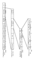
- Ceased
Links
Images























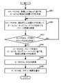











































Classifications
-
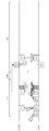
- H—ELECTRICITY
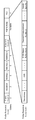
- H04—ELECTRIC COMMUNICATION TECHNIQUE
- H04B—TRANSMISSION
- H04B7/00—Radio transmission systems, i.e. using radiation field
- H04B7/02—Diversity systems; Multi-antenna system, i.e. transmission or reception using multiple antennas
- H04B7/04—Diversity systems; Multi-antenna system, i.e. transmission or reception using multiple antennas using two or more spaced independent antennas
- H04B7/06—Diversity systems; Multi-antenna system, i.e. transmission or reception using multiple antennas using two or more spaced independent antennas at the transmitting station
-
- H—ELECTRICITY
- H04—ELECTRIC COMMUNICATION TECHNIQUE
- H04W—WIRELESS COMMUNICATION NETWORKS
- H04W16/00—Network planning, e.g. coverage or traffic planning tools; Network deployment, e.g. resource partitioning or cells structures
- H04W16/24—Cell structures
- H04W16/28—Cell structures using beam steering
-
- H—ELECTRICITY
- H04—ELECTRIC COMMUNICATION TECHNIQUE
- H04W—WIRELESS COMMUNICATION NETWORKS
- H04W8/00—Network data management
Definitions
- the present disclosure relates to a wireless communication device.
- a wireless communication device for example, AP (Access Point) / PCP (PBSS Central Point): hereinafter referred to as AP / PCP
- DMG directional
- a discovery procedure including transmission and reception of signals called multi-gigabit beacons is performed to discover a wireless communication apparatus (for example, STA (Station)) as a communication partner.
- the present invention contributes to provision of a wireless communication apparatus capable of realizing high-speed discovery even when STAs to be discovered increase in discovery by the DMG beacon.
- a wireless communication apparatus is a DM (DMG beacon) that indicates a DMG beacon transmitted by an A-STA (Active Scanning Station) as a directional multi-gigabit (DMG) beacon in a beacon transmission interval (BTI).
- DMG beacon indicates a DMG beacon transmitted by an A-STA (Active Scanning Station) as a directional multi-gigabit (DMG) beacon in a beacon transmission interval (BTI).
- BTI beacon transmission interval
- a frame configuration unit that omits signal generation in A-BFT (Association Beamforming Training) and generates a signal in DTI (Data Transfer Interval), and the BTI with respect to the one or more first DMG beacons.
- A-BFT Association Beamforming Training
- DTI Data Transfer Interval
- high-speed discovery can be realized even when the number of STAs to be discovered increases in discovery by the DMG beacon.
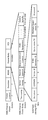
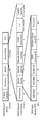
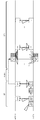
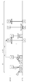
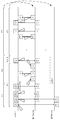
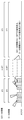
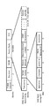
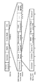
- Diagram showing an example of beacon interval including BTI Diagram showing an example of beam pattern of an omni (Omni) transmission sector Diagram showing an example of beam pattern of directional sector Figure showing an example beam pattern of Quasi-Omni transmit sector Figure showing an example of beacon transmission and reception in the 2.4 GHz or 5 GHz frequency band (microwave band) Figure showing an example of beacon transmission and reception in the 60 GHz frequency band (millimeter wave band) Diagram showing an example of beam pattern relationship Diagram showing an example of beam pattern relationship Diagram showing an example of beam pattern relationship Diagram showing an example of beam pattern relationship Diagram showing an example of beam pattern relationship A diagram showing an example of the format of a DMG beacon frame A diagram showing another example of a DMG beacon frame format Sequence diagram showing a first example of a discovery procedure using DMG beacons Sequence diagram showing a second example of a discovery procedure using DMG beacons Flow chart showing a first example of a conventional discovery procedure Flow chart showing a first example of a conventional discovery procedure Flow chart showing a first example of a conventional discovery procedure
- a diagram showing an example of a frame format of a DMG beacon according to the first embodiment A sequence diagram showing a first modification of the discovery procedure according to the first embodiment
- a sequence diagram showing a second modification of the discovery procedure according to the first embodiment Flow chart showing an example of a discovery procedure according to the first embodiment
- Flow chart showing an example of a discovery procedure according to the first embodiment Flow chart showing an example of a discovery procedure according to the first embodiment
- Block diagram showing an example of the configuration of a wireless communication apparatus according to Embodiment 1 A sequence diagram showing an example of a discovery procedure according to Embodiment 2.
- Flow chart showing an example of a discovery procedure according to the second embodiment A sequence diagram showing an example of a discovery procedure according to Embodiment 3.
- FIG. 4 A sequence diagram showing a first example of a discovery procedure according to Embodiment 4.
- FIG. 4 A sequence diagram showing a second example of a discovery procedure according to Embodiment 4.
- the flowchart which shows one example of the discovery procedure which relates to the form 4 of execution Block diagram showing an example of the configuration of a wireless communication apparatus according to Embodiment 4
- a diagram showing a first example of a frame format of a DMG beacon according to the fifth embodiment A diagram showing a second example of a frame format of a DMG beacon according to the fifth embodiment
- the flowchart which shows one example of the discovery procedure which relates to the form 5 of execution The flowchart which shows one example of the discovery procedure which relates to the form 5 of execution
- a sequence diagram showing an example of a discovery procedure according to the sixth embodiment Flowchart showing an example of a
- FIG. 36 is a diagram showing a first example of a frame format of a DMG beacon according to a sixteenth embodiment.
- FIG. 36 shows a second example of a frame format of a DMG beacon according to the sixteenth embodiment.
- a sequence diagram showing an example of a discovery procedure according to the sixteenth embodiment Flowchart showing an example of a discovery procedure according to the sixteenth embodiment Flowchart showing an example of a discovery procedure according to the sixteenth embodiment
- FIG. 36 shows an example of a DMG beacon frame format for transmission using the directional sector according to the seventeenth embodiment.
- FIG. 32 is a diagram showing an example of the format of a DMG beacon frame transmitted using a pseudo omni transmission sector according to the seventeenth embodiment
- a sequence diagram showing a first example of a discovery procedure according to the seventeenth embodiment A sequence diagram showing a second example of the discovery procedure according to the seventeenth embodiment
- Flow chart showing an example of a discovery procedure according to the seventeenth embodiment Flow chart showing an example of a discovery procedure according to the seventeenth embodiment
- FIG. 52 shows an example of a frame format of a DMG beacon according to the eighteenth embodiment
- FIG. 52 shows a first modification of information on beacon intervals in the eighteenth embodiment.
- FIG. 52 shows a second modification of information on beacon intervals in the eighteenth embodiment.
- a flowchart showing an example of a discovery procedure according to the twenty-first embodiment A sequence diagram showing an example of a discovery procedure according to the twenty-second embodiment
- a flowchart showing an example of a discovery procedure according to the twenty-second embodiment A sequence diagram showing a first example of a discovery procedure according to the twenty-third embodiment
- a sequence diagram showing a second example of a discovery procedure according to the twenty-third embodiment A flowchart showing an example of a discovery procedure according to the twenty-third embodiment
- a sequence diagram showing an example of a discovery procedure according to the twenty-fourth embodiment A flowchart illustrating an example of a discovery procedure according to the twenty-fourth embodiment
- a flowchart illustrating an example of a discovery procedure according to the twenty-fourth embodiment A flowchart illustrating an example of a discovery procedure according to the twenty-fourth embodiment
- a sequence diagram showing an example of a discovery procedure according to the twenty-fifth embodiment A flowchart showing an example of a discovery procedure according to the twenty-fifth embodiment
- a sequence diagram showing a second example of a discovery procedure according to Embodiment 29 A flowchart showing an example of a discovery procedure according to the twenty-ninth embodiment A sequence diagram showing an example of a discovery procedure according to the thirtieth embodiment Flow chart showing an example of a discovery procedure according to the thirtieth embodiment Flow chart showing an example of a discovery procedure according to the thirtieth embodiment A sequence diagram showing an example of a discovery procedure according to Embodiment 31.
- FIG. 1 is a diagram illustrating an example of a beacon interval including a BTI.
- the start timing of the beacon interval (BI) is called TBTT.
- BI includes BHI (Beacon Header Interval) and DTI (Data Transfer Interval).
- the length of BI is set to, for example, about 100 ms.
- BHI includes BTI, A-BFT (Association Beamforming Training) and ATI (Announcement Transmission Interval).
- BTI Basic Service Set
- BTI is used for BFT (Beamforming Training).
- the length of BTI is set to, for example, about 0.3 ms.
- A-BFT a response to the BFT performed in BTI is sent. This A-BFT may be omitted. Also, the length of A-BFT is set to, for example, about 0.6 ms.
- DTI includes CBAP (Contention Based Access Period) and SP (Service Period). Data communication is performed in DTI. Also, DTI is used for a probe request (Probe Request) frame and / or a probe response (Probe Response) frame. Moreover, DTI is used for transmission of a connection frame (Association Frame). For example, the transmission / reception time of the probe request frame is set to about 5 ms.
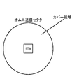
- FIG. 2A is a diagram showing an example of a beam pattern of an omni transmission sector.
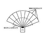
- FIG. 2B is a diagram showing an example of a beam pattern of a directional sector.
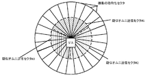
- FIG. 2C is a diagram showing an example of a beam pattern of a quasi-Omni transmission sector.
- the STA forms one of the sectors shown in FIGS. 2A to 2C and performs the BFT process.
- the AP / PCP also executes the BFT process, for example, by forming a sector of any of the beam patterns shown in FIGS. 2A to 2C.
- 2A to 2C show transmission sectors that transmit signals, but also when receiving signals, any sector of an omni reception sector, a directional sector, or a pseudo-omni reception sector Form
- the omni transmission sector of FIG. 2A is used, for example, in a 2.4 GHz or 5 GHz frequency band (microwave band).
- a 2.4 GHz or 5 GHz frequency band microwave band
- omni transmission sectors are often not used because propagation loss is high.
- the directional sector of FIG. 2B is used, for example, to overcome propagation loss and achieve sufficient communication range.
- the STAs switch in multiple directions to form directional sectors.
- the quasi-omni transmission sector of FIG. 2C is a pattern that has a shorter communication range than the directional sector, but covers a wider directivity (a wider angular range) compared to the directional sector.
- the pseudo-omni transmission sector is used, for example, for the reception of unscheduled DMG beacons.
- beacon transmission / reception is performed in BTI using a pseudo omni reception sector.
- FIG. 3A is a diagram showing an example of transmission and reception of beacons in a frequency band (microwave band) of 2.4 GHz or 5 GHz.
- FIG. 3B is a diagram illustrating an example of transmission and reception of beacons in a 60 GHz frequency band (millimeter wave band).
- the AP transmits one beacon using the omni transmission sector, and the STA receives the beacon transmitted by the AP using the omni transmission sector.
- the AP transmits beacons in all directions at one time.
- the AP switches the directional sector in a plurality of directions to transmit a DMG beacon, and the STA receives a DMG beacon transmitted by the AP using a pseudo omni reception sector.
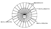
- FIG. 4A and FIG. 4B are diagrams showing an example of the relationship of beam patterns.
- FIG. 4A is an example in which a terminal that transmits and receives DMG beacons (hereinafter, appropriately referred to as DMG STA) covers an angular range of a plurality of directional sectors by one pseudo omni transmission sector.
- FIG. 4B shows that the DMG STA supports a plurality of pseudo omni transmission sectors (in the example of FIG. 4 B, pseudo omni transmission sector # 1 to pseudo omni transmission sector # 3), and each pseudo omni transmission sector has a plurality of directivity It is an example which covers the angle range of a sector.
- the directional sector and the pseudo-omni receiving sector for example, in the 60 GHz millimeter wave band, the relationship described below is assumed.
- 5A and 5B are diagrams showing an example of the relationship between beam patterns.
- FIG. 5A is an example in which the DMG STA covers the angular range of a plurality of directional sectors by one pseudo omni reception sector.
- FIG. 5B shows that the DMG STA supports a plurality of pseudo omni reception sectors (in the example of FIG. 5 B, pseudo omni reception sector # 1 to pseudo omni reception sector # 3), and each pseudo omni reception sector has a plurality of directivity It is an example which covers the angle range of a sector.
- the DMG STA supports simultaneously operating a plurality of pseudo-omni receiving sectors, thereby being able to receive a frame from any direction.
- IEEE 802.11ad-2012 of Non-Patent Document 1 two forms of beamforming training are defined.
- the first sector level sweep (SLS) performs coarse beamforming training
- the second beam refinement protocol (BRP) performs fine beamforming training. These are described in DMG beamforming in Section 9.35 of IEEE 802.11ad-2012 in Non-Patent Document 1.
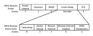
- FIG. 6 is a diagram showing an example of the format of a DMG beacon frame.
- FIG. 6 shows the fields included in the DMG beacon frame and the size of each field in octets.
- the format of FIG. 6 is defined in section 8.3.4.1 DMG beacon of IEEE 802.11ad-2012 of Non-Patent Document 1.
- a DMG beacon frame includes a Frame Control field, a Duration field, a BSSID field, a Frame Body field, and an FCS field.
- the Frame Body field has a plurality of fields including a Timestamp field, a Sector Sweep field, a Beacon Interval field, a Beacon Interval Control field, and a DMG parameters field.
- the Beacon Interval Control field includes, for example, a 1-bit Discovery Mode subfield.
- the DMG beacon since a plurality of DMG beacons are transmitted at a relatively low transmission rate (for example, in the Control PHY) in BTI, it is desirable to make the size of the DMG beacons relatively small. Therefore, the DMG beacon has a main field, and other information may be transmitted by a frame (for example, a probe frame described later) transmitted using a directional sector after the BFT is completed.
- a frame for example, a probe frame described later
- FIG. 7 is a diagram showing another example of the format of the DMG beacon frame.
- the DMG beacon in FIG. 7 is a beacon including a Timestamp field, a Sector Sweep field, a Beacon Interval field, a Beacon Interval Control field, and a DMG parameters field, which are main fields, of a plurality of fields in the Frame Body field.
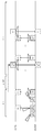
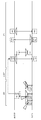
- FIG. 8 is a sequence diagram showing a first example of a discovery procedure using a DMG beacon.
- the first example is an example of a discovery procedure performed by a STA actively performing scanning by transmitting a DMG beacon.
- FIG. 8 shows transmission and reception of signals between a peer STA (Peer STA) including an AP / PCP and an STA (Active scanning STA, hereinafter referred to as A-STA) that actively executes scanning.
- the horizontal axis in FIG. 8 indicates the time axis, and among the blocks aligned in the time axis direction, a solid line block indicates a signal to be transmitted and a signal to receive the block indicated by a broken line. In the block, the content of the signal to be transmitted or received is shown. Further, in FIG. 8, the shape of a sector (a pseudo omni sector or a directional sector) used by a peer STA or an A-STA for transmitting or receiving a signal corresponding to each block is attached to the block.
- a sector a pseudo omni sector or a directional sector
- the discovery procedure of FIG. 8 includes a discovery process in DMG and an association process.
- the discovery process in DMG includes beamforming training process and probe exchange process.
- the beamforming training process is a process for determining which direction sector (may be called an antenna or sector) is the best (best sector).
- Beamforming training processing includes BTI processing and A-BFT processing.
- discovery process in DMG may be performed after the association process.
- the A-STA switches the directional sector in a plurality of directions, and a DMG beacon frame (hereinafter referred to as “DBcn” as appropriate) is transmitted to surrounding wireless communication devices (eg, peer STA or AP / Send to PCP).
- the A-STA sets the discovery mode sub-field (hereinafter referred to as “DM” as appropriate) to 1 in the transmitting DBcn.
- DM 1 indicates that it is DBcn transmitted by the A-STA.
- the AP / PCP that receives the DBcn transmitted by the A-STA switches the directional sector in multiple directions and describes it as an SSW frame (hereinafter referred to as "SSW" as appropriate) Send).
- the SSW includes a beam index (an index indicating a sector used by the A-STA for transmission of the DBcn) included in the DBcn received by the AP / PCP.
- the A-STA that has received the SSW transmits feedback (SSW-FB) for the SSW to the AP / PCP.
- the A-STA uses a sector (best sector in the A-STA) corresponding to the beam index included in the SSW.
- the SSW-FB includes a beam index (an index indicating a sector used for transmission of the SSW by the AP / PCP) included in the SSW received by the A-STA.
- FIG. 9 is a sequence diagram showing a second example of a discovery procedure using a DMG beacon.
- a second example is an example of a discovery procedure performed by a STA that is actively performing a scan receiving a DMG beacon.
- the difference between the first example of FIG. 8 and the second example of FIG. 9 is that in the second example of FIG. 9, the AP / PCP transmits DBcn in the BTI process, and in the A-BFT process, A-STA transmits SSW, and AP / PCP transmits SSW-FB.
- the A-STA and AP / PCP perform a discovery process including determination of the best sector.
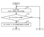
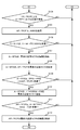
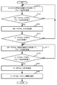
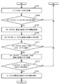
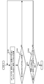
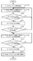
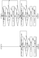
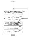
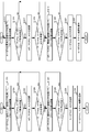
- FIGS. 10A-10C are flowcharts showing a first example of a conventional discovery procedure.
- the flowcharts of FIGS. 10A-10C correspond to the discovery procedure shown in FIG.
- the flowcharts of FIG. 10A to FIG. 10C show a discovery procedure performed between A-STA and AP / PCP as an example, the communication partner of A-STA is a peer STA instead of AP / PCP. It may be
- step S101 the A-STA (initiator) transmits DBcn in which the discovery mode (DM) is set to 1 in order to start BFT processing with a communicable AP / PCP (responder).
- DBcn is transmitted as a transmit sector sweep having frames transmitted using directional sectors in different directions.
- step S102 the AP / PCP determines whether to receive DBcn during BTI.
- step S102 When the AP / PCP does not receive DBcn during BTI (NO in step S102), the flow returns to the process of step S101.
- step S103 the AP / PCP determines the best transmission sector (best sector) of the A-STA.
- step S104 the AP / PCP determines whether to respond in A-BFT.
- the AP / PCP determines, for example, whether or not there is a schedule conflict, or whether to respond with the NAV setting.
- step S104 When the AP / PCP does not respond in the A-BFT (NO in step S104), the flow returns to the process of step S101.
- step S105 the AP / PCP transmits an SSW to perform BFT.
- the SSW is transmitted using directional sectors in a plurality of directions different from one another. Transmission of SSW may be referred to as transmission sector sweep.
- the AP / PCP notifies the best transmission sector of the A-STA by SSW.
- step S106 the A-STA determines whether to receive an SSW during A-BFT.
- step S106 When the A-STA does not receive the SSW during A-BFT (NO in step S106), the flow returns to the process of step S101.
- the A-STA When the A-STA receives the SSW during A-BFT (YES in step S106), the A-STA stores the best transmission sector of the A-STA notified by the SSW in S107.
- step S108 the A-STA determines the best transmission sector (best sector) of the AP / PCP.
- step S109 the A-STA determines whether to transmit SSW-FB to this AP / PCP (that is, AP / PCP as a transmission source of SSW).
- step S109 When the A-STA does not transmit SSW-FB to this AP / PCP (that is, AP / PCP of SSW transmission source) (NO in step S109), the flow returns to the process of step S101.
- step S110 A-STA includes one SSW. Send the FB using the best transmit sector. At that time, the A-STA notifies the best transmission sector of AP / PCP by SSW-FB.
- step S111 the AP / PCP determines whether SSW-FB is received during A-BFT.
- step S111 When AP / PCP does not receive SSW-FB during A-BFT (NO in step S111), the flow returns to the process of step S101.
- AP / PCP When AP / PCP receives SSW-FB during A-BFT (YES in step S111), AP / PCP stores the best transmission sector of AP / PCP notified by SSW-FB in step S112.
- step S113 the A-STA sends a probe request using the best sending sector.
- step S114 the AP / PCP determines whether or not a probe request has been received during DTI.
- step S114 When the AP / PCP does not receive a probe request during DTI (NO in step S114), the flow returns to the process of step S113.
- the AP / PCP When the AP / PCP receives a probe request during DTI (YES in step S114), it transmits an ACK to the A-STA in step S115.
- step S116 the A-STA determines whether an ACK has been received during DTI.
- step S116 If the A-STA does not receive an ACK during DTI (NO in step S116), the flow returns to the process of step S113.
- the AP / PCP transmits a probe response using the best transmission sector in step S117.
- step S118 the A-STA determines whether a probe response has been received during DTI.
- step S118 If the A-STA does not receive a probe response during DTI (NO in step S118), the flow returns to the process of step S117.
- the A-STA receives a probe response during DTI (YES in step S118), it sends an ACK to AP / PCP in step S119.
- step S120 the A-STA notifies the AP / PCP of the scan result, and completes the discovery.
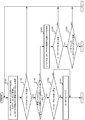
- FIGS. 11A to 11C are flowcharts showing a second example of the conventional discovery procedure.
- the flowcharts of FIGS. 11A-11C correspond to the discovery procedure shown in FIG. 11A to 11C show a discovery procedure performed between A-STA and AP / PCP as an example, but the communication partner of A-STA is a peer STA instead of AP / PCP. It may be
- step S141 the AP / PCP (initiator) transmits DBcn in which the discovery mode (DM) is set to 0 in order to start BFT processing with a communicable A-STA (responder).
- DBcn is transmitted as a transmit sector sweep having frames transmitted using directional transmit sectors in different directions.
- step S142 the A-STA determines whether to receive DBcn during BTI.
- step S142 If the A-STA does not receive DBcn during BTI (NO in step S142), the flow returns to the process of step S141.
- A-STA receives DBcn during BTI (YES in step S142), it determines the best transmission sector (best sector) of AP / PCP in step S143.
- step S144 the A-STA determines whether an A-BFT exists after the BTI. For example, the determination as to whether or not an A-BFT exists after a BTI is performed based on a field (Next A-BFT field (see FIG. 61 described later in the Beacon Interval Control field) included in DBcn).
- a field Next A-BFT field (see FIG. 61 described later in the Beacon Interval Control field) included in DBcn).
- step S144 If A-BFT does not exist after BTI (NO in step S144), the flow returns to the process of step S141.
- A-STA determines in step S145 whether to respond in A-BFT. The A-STA makes this determination, for example, based on whether or not there is a schedule conflict or by setting the NAV.
- step S145 If the A-STA does not respond in A-BFT (NO in step S145), the flow returns to the process of step S141.
- step S146 SSW is transmitted to perform BFT.
- the SSW is transmitted using directional sectors in a plurality of directions different from one another. Transmission of SSW may be referred to as transmission sector sweep.
- the A-STA notifies the best transmission sector of the AP / PCP by SSW.
- step S147 the AP / PCP determines whether to receive an SSW during A-BFT.
- step S147 When AP / PCP does not receive SSW during A-BFT (NO in step S147), the flow returns to the process of step S141.
- AP / PCP When AP / PCP receives SSW during A-BFT (YES in step S147), AP / PCP stores the best transmission sector of AP / PCP notified by SSW in step S148.
- step S149 the AP / PCP determines the best transmission sector (best sector) of the A-STA.
- step S150 the AP / PCP determines whether to transmit the SSW-FB to this A-STA (ie, the A-STA of the transmission source of the SSW).
- step S150 When the AP / PCP does not transmit SSW-FB to this A-STA (A-STA of SSW transmission source) (NO in step S150), the flow returns to the process of step S141.
- step S150 When AP / PCP transmits SSW-FB to this A-STA (A-STA of SSW transmission source) (YES in step S150), in step S151, the AP / PCP transmits one SSW-FB. Send using the best sending sector. The AP / PCP notifies the best transmitting sector of the A-STA by SSW-FB.
- step S152 the A-STA determines whether SSW-FB has been received during A-BFT.
- step S152 If the A-STA does not receive the SSW-FB during A-BFT (NO in step S152), the flow returns to the process of step S141.
- step S152 When A-STA receives SSW-FB during A-BFT (YES in step S152), in step S153, A-STA stores the best transmission sector of A-STA notified by SSW-FB.
- step S154 the A-STA sends a probe request using the best sending sector.
- step S155 the AP / PCP determines whether or not a probe request has been received during DTI.
- step S155 When the AP / PCP does not receive a probe request during DTI (NO in step S155), the flow returns to the process of step S154.
- the AP / PCP receives a probe request during DTI (YES in step S155), it transmits an ACK to the A-STA in step S156.
- step S157 the A-STA determines whether an ACK has been received during DTI.
- step S157 If the A-STA does not receive an ACK during DTI (NO in step S157), the flow returns to the process of step S154.
- step S158 the AP / PCP transmits a probe response using the best transmission sector.
- step S159 the A-STA determines whether a probe response has been received during DTI.
- step S159 If the A-STA does not receive a probe response during DTI (NO in step S159), the flow returns to the process of step S158.
- the A-STA receives a probe response during DTI (YES in step S159), it transmits an ACK to AP / PCP in step S160.
- step S161 the A-STA notifies the AP / PCP of the scan result, and completes the discovery.
- FIG. 12 is a diagram showing a first example of matters to be considered in the conventional discovery procedure.
- FIG. 12 is an example in which a schedule conflict occurs in the peer STA during the A-BFT processing period of the discovery procedure shown in FIG.
- the SSW since schedule collision occurs in the peer STA during the A-BFT processing period, the SSW is not transmitted to the A-STA. In this case, since the A-STA performs beamforming training processing in the next BTI processing period and A-BFT processing period, a delay occurs until the processing is completed.
- the delay time to occur is, for example, about 200 ms.
- FIG. 13 is a diagram showing a second example of matters to be considered in the conventional discovery procedure.
- FIG. 13 is an example of executing the discovery procedure shown in FIG. 9 between an AP / PCP performing scheduling and an A-STA.
- the A-STA does not transmit the SSW in the A-BFT period after receiving the DBcn transmitted by the AP / PCP. Therefore, since the A-STA performs beamforming training processing in the next BTI processing period and the next A-BFT processing period, a delay occurs until the processing is completed.
- the delay time to occur is, for example, about 100 ms.
- FIG. 14 is a diagram showing a third example of matters to be considered in the conventional discovery procedure.
- FIG. 14 is an example of executing the discovery procedure shown in FIG. 9 between a peer STA and two A-STAs (A-STA1 and A-STA2).
- full collision occurs in the transmission of SSW during the BFT period of A-STA1.
- a full collision indicates that there is no SSW successfully received at the peer STA during A-BFT.
- a partial collision occurs in the transmission of the SSW of the A-STA 2. Partial collision indicates that there is at least one SSW that is not successfully received at the peer STA during A-BFT.
- the SSW transmitted by the A-STA 1 and the SSW transmitted by the A-STA 2 collide with each other to generate an error.
- the SSW transmitted by the A-STA 2 is received by the peer STA.
- the A-STA 2 and the peer STA perform probe exchange processing in the DTI period. Meanwhile, since the SSW transmitted by the A-STA 1 is not received by the peer STA, the beamforming training of the A-STA 1 and the peer STA is not completed. Therefore, in order for the A-STA 1 to perform beamforming training processing in the next BTI processing period and A-BFT processing period, a delay occurs until the processing is completed.
- the delay time to occur is, for example, about 200 ms when the communication partner of A-STA 1 is a peer STA, and about 100 ms when the communication partner of A-STA 1 is AP / PCP.
- FIG. 14 shows an example in which even if a partial collision occurs in the SSW transmission of the A-STA 2, probe exchange processing can be executed thereafter during the DTI period. Forming training may not be completed. This is because SSW-FB is transmitted to one STA.
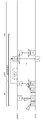
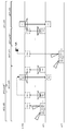
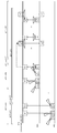
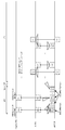
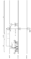
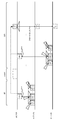
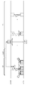
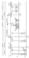
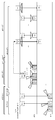
- FIG. 15 is a sequence diagram showing an example of a discovery procedure according to the first embodiment.
- the discovery procedure of FIG. 15 is an example in which the A-STA transmits DBcn in BTI, similarly to the discovery procedure shown in FIG.
- a discovery procedure performed between A-STA and AP / PCP is shown as an example, but the communication partner of A-STA is a peer STA instead of AP / PCP. It is good.
- the A-STA switches the directional sector in a plurality of directions in BTI, and transmits DBcn. Then, the A-STA transmits DBcn using a pseudo omni transmission sector in BTI. The A-STA sets DM to 1 in the transmitting DBcn. Also, the A-STA sets a quasi-omni indicator (Quasi-Omni Indicator: hereinafter referred to as “QO” as appropriate) included in DBcn to be transmitted using a quasi-omni transmission sector to 1. The pseudo omni indicator indicates whether the sector used for transmission is a pseudo omni transmission sector.
- QO quasi-omni indicator
- the pseudo omni indicator may be any one that can be used to determine whether or not minimal communication (eg, probe exchange) is possible without going through BFT.
- a transmitter eg, A-STA
- EIRP equivalent isotropically radiated power
- a receiver eg, AP / PCP or peer STA
- the AP / PCP receives DBcn transmitted using the directional sector and DBcn transmitted using the pseudo-omni transmission sector.
- the A-STA receives the probe response, and transmits an acknowledgment (ACK) indicating that the probe response has been received, using the pseudo omni transmission sector.
- ACK acknowledgment
- the pseudo omni transmission sector has a shorter communication range than the directional sector. Therefore, that the AP / PCP receives DBcn transmitted by the A-STA using the pseudo omni transmission sector means that the A-STA exists within a short communication range. This means that when the AP / PCP transmits a probe request using a pseudo-omni transmission sector, it is likely that the A-STA receives a probe request. Thus, the AP / PCP that has received DBcn using the pseudo omni transmission sector determines to start transmission using the pseudo omni transmission sector.
- the receiver of the DMG beacon receives the frame using the pseudo omni transmission sector before the beamforming training is completed. In the example of FIG. 15, it can be determined whether or not to transmit a probe response frame).
- FIG. 15 illustrates an example in which the receiver determines whether to use a pseudo omni transmission sector
- the present disclosure is not limited thereto.
- Various modifications are possible based on the relationship between the communication range (coverage) of the pseudo omni transmission sector and the pseudo omni reception sector. For example, various modifications are possible if the quasi-omni transmission sector of the STA covers a range similar to or less than the quasi-omni reception sector. Also, for example, if the STA supports multiple quasi-omni transmissions or receptions, various modifications are possible.
- FIG. 15 is an example in which the last one DBcn transmitted by the A-STA in the BTI is transmitted using a pseudo omni transmission sector, the present disclosure is not limited thereto.
- the number of DBcns transmitted using the pseudo omni transmission sector may be two or more, and the transmission timing is not limited to the end.
- FIG. 16 is a diagram showing an example of a frame format of a DMG beacon according to the first embodiment. Similar to FIG. 6, FIG. 16 shows the fields included in the DMG beacon frame and the size of each field in octets or bits.
- the format of the DMG beacon frame in FIG. 16 includes a Frame Control field, a Duration field, a BSSID field, a Frame Body field, and an FCS field.
- the Frame Body field has a plurality of fields including a Timestamp field, a Sector Sweep field, a Beacon Interval field, a Beacon Interval Control field, a DMG parameters field, and a Vendor Specific field.
- the Sector Sweep field includes a Direction sub-field, a CDON sub-field, a Sector ID sub-field, a DMG Antenna ID sub-field, a Quasi-Omni TX sub-field, and a Reserved sub-field.
- the Quasi-Omni TX sub-field is set to 1 for DMG beacons transmitted using pseudo-omni transmission sectors.
- the Quasi-Omni TX sub-field is set to 0 in a DMG beacon transmitted using a sector (for example, a directional sector) different from the pseudo omni transmission sector. Note that this setting may be reversed.
- the format of FIG. 16 is an example, and the present disclosure is not limited to this.
- the Quasi-Omni TX sub-field can be set to 1 bit in order to shorten the frame length of the DMG beacon, but may be 2 bits or more.
- transmission power information of EIRP may be transmitted to determine whether a pseudo omni transmission sector is used.
- FIG. 15 describes the transmission of the DMG beacon (DBcn) of the A-STA in one BTI period, the present disclosure is not limited to this.
- the A-STA may transmit a DMG beacon across multiple BTI periods.
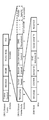
- FIG. 17A is a sequence diagram showing a first modified example of the finding procedure according to the first embodiment.
- the A-STA in the first BTI period, transmits DBcn using the first set of the directional sectors possessed by the A-STA, and transmits DBcn using the pseudo-omni transmission sector.
- the A-STA transmits DBcn using the second set, and transmits DBcn using the pseudo-omni transmission sector.
- FIG. 17B is a sequence diagram showing a second modified example of the discovery procedure according to the first embodiment.
- FIG. 17B is different from FIG. 17A in that A-STA does not transmit DBcn using a pseudo omni transmission sector in the second BTI period.
- the A-STA may transmit DBcn shown in FIGS. 17A and 17B.
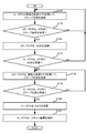
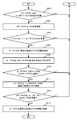
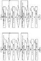
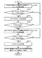
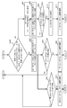
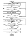
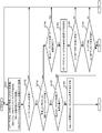
- FIGS. 18A-18C are flowcharts showing an example of a discovery procedure according to the first embodiment.
- the flowcharts of FIGS. 18A-18C correspond to the discovery procedure shown in FIG.
- step S201 the A-STA (initiator) uses a plurality of sectors including a pseudo omni transmission sector to start a BFT process with a communicable AP / PCP (responder) in a discovery mode (DM).
- DBcn is transmitted as a transmit sector sweep having frames transmitted using pseudo-omni transmit sectors and directional sectors in different directions.
- step S202 the AP / PCP determines whether to receive DBcn during BTI.
- step S202 When the AP / PCP does not receive DBcn during BTI (NO in step S202), the flow returns to the process of step S201.
- step S203 the AP / PCP determines whether the received DBcn includes DBcn transmitted in the pseudo omni transmission sector. This determination is performed, for example, based on whether or not the Quasi-Omni TX sub-field of DBcn is set to “TRUE” (for example, whether or not it is set to 1).
- AP / PCP determines the best transmission sector (best sector) of the A-STA in step S204. .
- step S205 the AP / PCP determines whether to respond in A-BFT.
- the AP / PCP is determined, for example, based on whether or not there is a schedule conflict or by setting the NAV.
- step S205 When the AP / PCP does not respond in A-BFT (NO in step S205), the flow returns to the process of step S201.
- the AP / PCP When the AP / PCP responds in the A-BFT (YES in step S205), the AP / PCP transmits an SSW to perform BFT in step S206.
- the SSW is transmitted using directional sectors in a plurality of directions different from one another. Transmission of SSW may be referred to as transmission sector sweep.
- the AP / PCP notifies the best transmission sector of the A-STA by SSW.
- step S207 the A-STA determines whether to receive an SSW during A-BFT.
- step S207 If the A-STA does not receive SSW during A-BFT (NO in step S207), the flow returns to the process of step S201.
- step S208 the best transmission sector of A-STA notified by SSW is stored.
- step S209 the A-STA determines the best transmission sector (best sector) of the AP / PCP.
- step S210 the A-STA determines whether to transmit SSW-FB to this AP / PCP (that is, AP / PCP of the transmission source of SSW).
- step S210 When the A-STA does not transmit SSW-FB to this AP / PCP (that is, AP / PCP of transmission source of SSW) (NO in step S210), the flow returns to the process of step S201.
- step S210 A-STA transmits SSW-FB to this AP / PCP (that is, AP / PCP of transmission source of SSW) (YES in step S210), in step S211, A-STA selects one SSW. Send the FB using the best transmit sector. At that time, the A-STA notifies the best transmission sector of AP / PCP by SSW-FB.
- step S212 the AP / PCP determines whether SSW-FB is received during A-BFT.
- step S212 When AP / PCP does not receive SSW-FB during A-BFT (NO in step S212), the flow returns to the process of step S201.
- AP / PCP When AP / PCP receives SSW-FB during A-BFT (YES in step S212), AP / PCP stores the best transmission sector of AP / PCP notified by SSW-FB in step S213.
- step S214 the A-STA sends a probe request using the best sending sector.
- step S215 the AP / PCP determines whether it has received a probe request during DTI.
- step S215 When the AP / PCP does not receive a probe request during DTI (NO in step S215), the flow returns to the process of step S214.
- step S216 the AP / PCP transmits an ACK to the A-STA using the pseudo omni transmission sector.
- step S217 the A-STA determines whether an ACK has been received during DTI.
- step S217 If the A-STA does not receive an ACK during DTI (NO in step S217), the flow returns to the process of step S214.
- the AP / PCP transmits a probe response using the best transmission sector in step S218.
- step S219 the A-STA determines whether it has received a probe response during DTI.
- step S218 If the A-STA does not receive a probe response during DTI (NO in step S219), the flow returns to the process of step S218.
- the A-STA receives a probe response during DTI (YES in step S219), it sends an ACK to AP / PCP in step S220.
- step S221 the A-STA notifies the AP / PCP of the scan result, and completes the discovery.
- AP / PCP transmits a probe response using the pseudo omni transmission sector in step S222.
- step S223 the A-STA determines whether it has received a probe response during DTI.
- step S223 If the A-STA does not receive a probe response during DTI (NO in step S223), the flow returns to the process of step S222.
- the A-STA receives a probe response during DTI (YES in step S223), it sends an ACK to AP / PCP in step S224.
- step S225 the A-STA notifies the AP / PCP of the scan result, and completes the discovery.
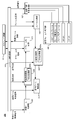
- FIG. 19 is a block diagram showing an example of the configuration of the wireless communication device (for example, peer STA, AP / PCP and A-STA) 100 according to the first embodiment.
- the wireless communication apparatus 100 includes a scheduler circuit 101, a sequence control circuit 102, a reception beam control unit 103, a reception processing circuit 104, a deframe processing circuit 105, a transmission frame generation circuit 106, a selection circuit 107, a framing circuit 108, and a transmission processing circuit. 109 and a transmission beam control unit 110.
- the scheduler circuit 101 performs scheduling in AP / PCP based on information (for example, various information included in a received frame) acquired from the sequence control circuit 102.
- the scheduler circuit 101 outputs information on scheduling to the sequence control circuit 102.
- the sequence control circuit 102 outputs a control signal for controlling each configuration based on information on scheduling. Further, the sequence control circuit 102 outputs various information included in the frame, which is acquired from the deframe circuit 105, to the scheduler circuit 101.
- the reception beam control unit 103 acquires a reception beam control signal (for example, an ID indicating a directional sector or a pseudo omni reception sector). Then, the reception beam control unit 103 receives the signal using the sector instructed by the reception beam control signal. Then, the reception beam control unit 103 outputs the received signal to the reception processing circuit 104.
- a reception beam control signal for example, an ID indicating a directional sector or a pseudo omni reception sector.
- the reception processing circuit 104 performs, for example, amplification processing on a signal acquired from the reception beam control unit 103 based on a reception request instructing a reception processing method (for example, amplification factor, reception frequency band, demodulation method), for example. , Receiving processing including frequency conversion processing and demodulation processing.
- the reception processing circuit 104 outputs the signal after reception processing to the deframe processing circuit 105.
- the deframe circuit 105 extracts the frame included in the signal acquired from the reception processing circuit 104 based on the deframe request including information on the type of the frame and the format, for example. Then, the deframe conversion circuit 105 acquires various information (for example, information of each field and subfield) included in the frame, and outputs the information to the sequence control circuit 102.
- the transmission frame generation circuit 106 generates a transmission frame and various information included in the transmission frame.
- the transmission frame generated by the transmission frame generation circuit 106 is, for example, a DMG beacon frame (DBcn), a probe request frame, and a probe response frame.
- the transmission frame generation circuit 106 outputs the generated frame and information to the selection circuit 107.
- the selection circuit 107 selects a frame to be transmitted from the frames acquired from the transmission frame generation circuit 106 based on the selection signal acquired from the sequence control circuit 102. Further, the selection circuit 107 selects the information included in the frame to be transmitted based on the selection signal. The selection circuit 107 outputs the selected frame and information to the framing circuit 108.
- the framing circuit 108 constructs a transmission frame from the frame and information acquired from the selection circuit 107 based on a framing request including information on the type of the frame and the format.
- the framing circuit 108 outputs the transmission frame to the transmission processing circuit 109.
- the transmission processing circuit 109 performs, for example, amplification processing, frequency conversion processing, and modulation processing on the acquired transmission frame based on a transmission request instructing a transmission processing method (for example, modulation method, amplification factor, transmission frequency band). Perform transmission processing including The transmission processing circuit 109 outputs the signal after transmission processing to the transmission beam control unit 110.
- a transmission processing method for example, modulation method, amplification factor, transmission frequency band.
- the transmission beam control unit 110 acquires a transmission beam control signal (for example, an ID indicating a directional sector or a pseudo omni reception sector). Then, the transmission beam control unit 110 transmits the signal after the transmission processing using the sector instructed by the transmission beam control signal.
- a transmission beam control signal for example, an ID indicating a directional sector or a pseudo omni reception sector.
- the A-STA transmits the DMG beacon using the pseudo omni transmission sector, and the AP / PCP (or peer STA) is transmitted using the pseudo omni transmission sector. It is determined whether the DMG beacon has been received.
- the AP / PCP or the peer STA
- receives the DMG beacon transmitted using the pseudo omni transmission sector it determines that the probe response frame can be transmitted using the pseudo omni transmission sector.
- the AP / PCP determines that communication using a pseudo-omni sector is possible, delays the A-BFT period and probe request reception, and transmits a probe response, thus causing delay. You can suppress and complete the discovery procedure.
- A-STA and the AP / PCP can perform data communication using a pseudo omni transmission sector.
- the A-STA and the AP / PCP (or peer STA) can perform, for example, short-range communication with a short communication distance or communication with a high data rate.
- the A-STA transmits the DMG beacon using the pseudo omni transmission sector and the directional sector
- the DMG beacon in which the AP / PCP (or peer STA) is transmitted using the pseudo omni transmission sector Even if it does not receive, the beamforming training process can be continued to receive the DMG beacons transmitted using the directional sector.
- the AP / PCP can determine the best transmitting sector of the A-STA by receiving the DMG beacon transmitted using the directional sector, and can feed back the determined best transmitting sector to the A-STA.
- data communication using the best transmission sector can be performed instead of the pseudo omni transmission sector.
- the AP / PCP can perform data communication using the best transmission sector when the communication distance is long and / or in the case of high rate communication.
- the pseudo omni transmission sector is described as an example, but a pseudo omni reception sector may be used from the symmetry of transmission and reception.
- Second Embodiment In the first embodiment, when AP / PCP receives DBcn transmitted from A-STA using pseudo omni transmission sector, it transmits a probe response to the A-STA using pseudo omni transmission. An example has been described. In the second embodiment, an example in which the AP / PCP broadcasts a probe response using a pseudo omni transmission sector will be described. In the second embodiment, a discovery procedure performed between A-STA and AP / PCP is shown as an example, but the communication partner of A-STA is a peer STA instead of AP / PCP. It is good.
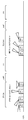
- FIG. 20 is a sequence diagram showing an example of a discovery procedure according to the second embodiment.
- DBcn transmitted by the A-STA # 1 is the same as the discovery procedure according to the first embodiment shown in FIG.
- the AP / PCP receives DBcn transmitted using the directional sector and DBcn transmitted using the pseudo-omni transmission sector.
- the A-STA # 1 When the A-STA # 1 receives the probe response, it notifies the AP / PCP that is the transmission source of the probe response of the scan result (not shown).
- A-STA # 2 different from A-STA # 1 receives a broadcast probe response
- A-STA # 2 that has received the probe response can discover the AP / PCP that has transmitted the probe response.
- FIG. 20 shows an example in which the last one DBcn transmitted by A-STA # 1 in BTI is transmitted using a pseudo omni transmission sector
- the present disclosure is not limited to this.
- the number of DBcns transmitted using the pseudo omni transmission sector may be two or more, and the transmission timing is not limited to the end.
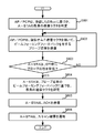
- FIG. 21 is a flowchart showing an example of a discovery procedure according to the second embodiment.
- B1 and B3 in FIG. 21 are connected to B1 and B3 in FIG. 18A, respectively.
- the AP / PCP broadcasts a probe response using the pseudo omni transmission sector in step S301.
- step S302 the A-STA determines whether it has received a probe response during DTI.
- step S302 If the A-STA does not receive a probe response during DTI (NO in step S302), the flow returns to the process of step S201 (see FIG. 18A).
- the A-STA When the A-STA receives a probe response during DTI (YES in step S302), it notifies the AP / PCP of the scan result in step S303, and completes the discovery.
- step S304 it is determined whether another STA different from the A-STA has received a probe response during DTI.
- step S304 If another STA does not receive a probe response during DTI (NO in step S304), the flow returns to the process of step S304.
- step S304 When the other STA receives the probe response during DTI (YES in step S304), the AP / PCP discovery process is completed in step S305.
- the AP / PCP can notify the presence of the AP / PCP to a plurality of STAs including the A-STA by broadcasting a probe response.
- the A-STA transmits the DMG beacon using the pseudo omni transmission sector, and the AP / PCP (or peer STA) is transmitted using the pseudo omni transmission sector. It is determined whether the DMG beacon has been received. Then, when the AP / PCP (or peer STA) receives the DMG beacon transmitted using the pseudo omni transmission sector, it broadcasts a probe response frame using the pseudo omni transmission sector.
- BSS information can be broadcast to STAs within the communication range of the pseudo omni transmission sector of AP / PCP (or peer STA) including the transmission source of DMG beacons, so that the discovery procedure for multiple STAs can be performed at high speed. Can be completed.
- the AP / PCP broadcasts the probe response using a directional sector, considering the narrowness of the angular range of the directional sector Even if there are multiple STAs in the AP / PCP neighborhood, there is a low probability that a probe response will arrive.
- the probe response is broadcasted using the pseudo omni transmission sector as in the second embodiment, the angular range of the pseudo omni transmission sector is wider than that of the directional sector, and thus exists near AP / PCP. There is a high probability that the probe response will reach more STAs.
- the AP / PCP broadcasts a probe response when it receives DBcn transmitted from one A-STA using a pseudo-omni transmission sector.
- the AP / PCP broadcasts a probe response when it receives DBcn transmitted from two or more A-STAs using pseudo omni transmission sectors.
- a discovery procedure performed between A-STA and AP / PCP is shown as an example, but the communication partner of A-STA is a peer STA instead of AP / PCP. It is good.
- FIG. 22 is a sequence diagram showing an example of a discovery procedure according to the third embodiment.
- DBcn transmitted by the A-STA is the same as the discovery procedure according to the first embodiment shown in FIGS.
- the AP / PCP receives DBcn from two A-STAs (A-STA # 1 and A-STA # 2).
- the AP / PCP receives the DBcn transmitted by each of the A-STA # 1 and the A-STA # 2 using the pseudo omni transmission sector. In such cases, the AP / PCP broadcasts a probe response during DTI. A-STA # 1 and A-STA # 2 receive the broadcast probe response and complete the process of the discovery procedure.
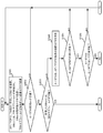
- FIG. 23 is a flowchart showing an example of a discovery procedure according to the third embodiment.
- B1 and B3 in FIG. 23 are connected to B1 and B3 in FIG. 18A, respectively.
- the AP / PCP receives the DBcn in step S401 in which two or more STAs are pseudo omni transmission sectors. It is determined whether the received DBcn is included.
- AP / PCP is a transmission destination using the pseudo omni transmission sector in step S402. Broadcast a probe response with the address broadcast address.
- A-STA # 1 When a probe response is broadcasted, processing of multiple A-STAs is performed in parallel. In the following, processing of each of two A-STAs (a first A-STA (A-STA # 1) and a second A-STA (A-STA # 2)) will be described.
- step S403 the first A-STA determines whether it has received a probe response during DTI.
- step S403 If the first A-STA does not receive a probe response during DTI (NO in step S403), the flow returns to the process of step S201 (see FIG. 18A).
- the first A-STA receives a probe response during DTI (YES in step S403), it notifies the AP / PCP of the scan result in step S404, and completes the discovery.
- step S405 the second STA determines whether it has received a probe response during DTI.
- step S405 If the second STA does not receive a probe response during DTI (NO in step S405), the flow returns to the process of step S201.
- the second STA receives a probe response during DTI (YES in step S405), it notifies the AP / PCP of the scan result in step S406, and completes the discovery.
- the AP / PCP received the DBcn transmitted by one A-STA in the pseudo omni transmission sector.
- the destination of the probe response is set to the A-STA that has transmitted DBcn in the pseudo omni transmission sector.
- step S408 the AP / PCP transmits (unicasts) a probe response to the A-STA using the pseudo omni transmission sector.
- step S409 the A-STA determines whether it has received a probe response during DTI.
- step S409 If the A-STA does not receive a probe response during DTI (NO in step S409), the flow returns to the process of step S408.
- the A-STA receives a probe response during DTI (YES in step S409), it sends an ACK to AP / PCP in step S410.
- step S411 the A-STA notifies the AP / PCP of the scan result, and completes the discovery.
- the AP / PCP can notify the presence of the AP / PCP to the plurality of A-STAs transmitting the DBcn by broadcasting the plurality of probe responses.
- the A-STA transmits the DMG beacon using the pseudo omni transmission sector, and the AP / PCP (or peer STA) is transmitted using the pseudo omni transmission sector. It is determined whether the received DMG beacons have been received from a plurality of A-STAs.
- the AP / PCP or peer STA
- receives DMG beacons transmitted using the pseudo omni transmission sector from a plurality of A-STAs the transmission address is set to the broadcast address using the pseudo omni transmission sector. Broadcast a probe response frame.
- BSS information can be broadcast more efficiently than unicasting a probe response to each A-STA, so that discovery procedures in a plurality of STAs can be completed at high speed.
- FIG. 24A is a sequence diagram showing a first example of a discovery procedure according to the fourth embodiment.
- a discovery procedure performed between A-STA and AP / PCP is shown as an example, but the communication partner of A-STA is a peer STA instead of AP / PCP. It is good.
- DBcn transmitted by the A-STA is the same as the discovery procedure according to the first embodiment shown in FIG.
- the AP / PCP receives DBcn transmitted using the directional sector and DBcn transmitted using the pseudo-omni transmission sector.
- the A-STA receives, in the DTI, a probe response to which a TRN-R subfield is added at a subsequent stage. At that time, A-STA first receives a probe response using pseudo omni reception sector (QO Rx), and then switches directivity sectors (Beamed Rx) in different directions from each other to receive TRN-R subfields. Do. Then, the A-STA determines the best sector of the A-STA based on the received signal quality of the TRN-R subfield.
- QO Rx pseudo omni reception sector
- Beamed Rx directivity sectors
- the A-STA transmits an ACK indicating that the probe response has been received, using the pseudo omni transmission sector or the best sector of the A-STA.
- the discovery procedure shown in FIG. 24A is an example in which the A-STA switches the directional sector and receives the TRN-R subfield to determine the best sector of the A-STA.
- FIG. 24B is a sequence diagram showing a second example of a discovery procedure according to the fourth embodiment.
- DBcn transmitted by the A-STA is the same as the discovery procedure according to the first embodiment shown in FIG.
- the AP / PCP receives DBcn transmitted using the directional sector and DBcn transmitted using the pseudo-omni transmission sector.
- the AP / PCP first transmits a probe response using a pseudo omni transmission sector, and then switches directivity sectors in different directions from each other to transmit a TRN-T subfield.
- the A-STA receives, in the DTI, a probe response in which the TRN-T subfield is added at a subsequent stage. At this time, the A-STA receives a probe response and a TRN-T subfield using a pseudo omni reception sector (QO Rx). Then, the A-STA determines the best sector of the AP / PCP based on the received signal quality of the TRN-T subfield.
- QO Rx pseudo omni reception sector
- the A-STA transmits an ACK indicating that the probe response has been received, using the pseudo omni transmission sector. Then, the A-STA transmits a BRP frame including information on the best sector of AP / PCP using a pseudo omni transmission sector.
- the AP / PCP switches the TRN-T sub-field by switching the directional sector, and the A-STA receives the TRN-T sub-field to transmit the AP / PCP.
- FIG. 25 is a flowchart of an example of a discovery procedure according to the fourth embodiment.
- B1 in FIG. 25 is connected to B1 in FIG. 18A.
- AP / PCP When AP / PCP includes DBcn transmitted in the pseudo omni transmission sector (YES in step S203), the AP / PCP uses the pseudo omni transmission sector in step S501 to set the TRN-R subfield to a later stage. Send a containing probe response.
- step S502 the A-STA determines whether it has received a probe response during DTI. At that time, A-STA first receives a probe response using pseudo omni reception sector (QO Rx), and then switches directivity sectors (Beamed Rx) in different directions from each other to receive TRN-R subfields. Do.
- QO Rx pseudo omni reception sector
- Beamed Rx directivity sectors
- step S502 If the A-STA does not receive a probe response during DTI (NO in step S502), the flow returns to the process of step S501.
- the A-STA When the A-STA receives a probe response within a predetermined period (timeout period) of DTI (YES in step S502), the reception result of the TRN-R subfield received using the directional sector in step S503 Based on (eg, received power), the best sector of the A-STA is determined.
- step S504 the A-STA transmits an ACK. Then, in step S505, the A-STA notifies the AP / PCP of the scan result, and completes the discovery.
- FIG. 26 is a block diagram showing an example of a configuration of a wireless communication apparatus (for example, AP / PCP or A-STA) 200 according to the fourth embodiment.
- a wireless communication apparatus for example, AP / PCP or A-STA
- FIG. 26 the same components as in FIG. 19 will be assigned the same reference numerals and descriptions thereof will be omitted.
- the reception beam control unit 203 When receiving the probe response including the TRN-R subfield (that is, in the case of A-STA in FIG. 24A), the reception beam control unit 203 receives the probe response using the pseudo omni reception sector, and receives the directional sector. The receiving sector is controlled to switch and receive the TRN-R sub-field.
- the reception beam control unit 203 uses the pseudo omni reception sector to transmit the probe response and the TRN-T subfield. Control the receiving sector to receive.
- the reception processing circuit 204 performs, for example, amplification processing on a signal acquired from the reception beam control unit 203 based on a reception request instructing a reception processing method (for example, amplification factor, reception frequency band, demodulation method), for example. , Receiving processing including frequency conversion processing and demodulation processing.
- the reception processing circuit 204 outputs the signal after reception processing to the deframe processing circuit 205.
- the reception processing circuit 204 further includes a TRN processing unit 204a.
- the TRN processing unit 204a calculates the reception result (for example, received power) of the TRN-R subfield or the TRN-T subfield included in the signal acquired from the reception beam control unit 203, and the calculation result is deframed circuit 205. Output to
- the deframe circuit 205 extracts a frame included in the signal acquired from the reception processing circuit 204 based on the deframe request including information on the type and format of the frame, for example. Then, the deframe circuit 205 acquires various information (for example, information of each field and subfield) included in the frame, and outputs the information to the sequence control circuit 202.
- the deframe conversion circuit 205 outputs the calculation result acquired from the reception processing circuit 204 to the sequence control circuit 202.
- the sequence control circuit 202 outputs a control signal for controlling each configuration based on information on scheduling. Further, the sequence control circuit 202 outputs various information included in the frame, which is acquired from the deframe forming circuit 205, to the scheduler circuit 101.
- the sequence control circuit 202 determines the best sector based on the calculation result acquired from the deframer circuit 205. For example, when the sequence control circuit 202 acquires the calculation result of the received signal quality of the TRN-R sub-field from the deframe forming circuit 205, it determines the best sector of the wireless communication apparatus 200. Also, for example, when the sequence control circuit 202 acquires the calculation result of the received signal quality of the TRN-T sub-field from the deframe forming circuit 205, it determines the best sector of the communication partner.
- the transmission processing circuit 209 performs, for example, amplification processing, frequency, or the like, on the transmission frame acquired from the framing circuit 108 based on the transmission request instructing the transmission processing method (for example, modulation method, amplification factor, transmission frequency band). It performs transmission processing including conversion processing and modulation processing.
- the transmission processing method for example, modulation method, amplification factor, transmission frequency band.
- the transmission processing circuit 209 further includes a TRN processing unit 209a.
- the TRN processing unit 209a adds a TRN-R subfield or a TRN-T subfield to the probe response frame based on the instruction of the sequence control circuit 202.
- the transmission processing circuit 209 outputs the probe response frame to which the TRN sub-field is added to the transmission beam control unit 210.
- the number of TRN subfields to be added may be one or more, and in the following description, they will be described as TRN subfields regardless of the number of TRN subfields.
- the transmission beam control unit 210 acquires a transmission beam control signal (for example, an ID indicating a directional sector or a pseudo omni reception sector). Then, the transmission beam control unit 210 transmits the signal after the transmission processing using the sector instructed by the transmission beam control signal.
- a transmission beam control signal for example, an ID indicating a directional sector or a pseudo omni reception sector.
- the transmission beam control unit 210 When transmitting the probe response frame including the TRN-R subfield (in the case of AP / PCP in FIG. 24A), the transmission beam control unit 210 transmits the probe response and the TRN-R subfield using the pseudo omni transmission sector. Control the sending sector to
- the transmission beam control unit 210 transmits a probe response using a pseudo omni transmission sector to And control the transmitting sector to transmit the TRN-T sub-field.
- the AP / PCP (or peer STA) transmits a probe response to which a TRN-T subfield or a TRN-R subfield is added.
- the A-STA can determine the best sector of the A-STA or the best sector of the AP / PCP (or peer STA)
- subsequent data communication can be performed without additional processing relating to beamforming training. Can be done efficiently.
- the A-STA supports a plurality of pseudo omni transmission sectors.
- the A-STA transmits DBcn using a plurality of pseudo omni transmission sectors, and receives probe responses transmitted from the AP / PCP using a plurality of pseudo omni reception sectors.
- a discovery procedure performed between A-STA and AP / PCP is shown as an example, but the communication partner of A-STA is a peer STA instead of AP / PCP. It is good.
- FIG. 27A is a diagram illustrating a first example of a frame format of a DMG beacon according to a fifth embodiment.
- FIG. 27B is a diagram showing a second example of the frame format of the DMG beacon according to the fifth embodiment.
- 27A and FIG. 27B indicate fields included in a DMG beacon frame and the size of each field in octets or bits, as in FIG.
- the format of the DMG beacon frame in FIGS. 27A and 27B is different from that in FIG. 16 in the configuration within the Sector Sweep field.
- the Sector Sweep field of the DMG beacon frame format in FIG. 27A includes the Direction subfield, the CDOWN subfield, the Sector ID subfield, the DMG Antenna ID subfield, the Quasi-Omni TX subfield, the Multiple Quasi-omni TX subfield, and , Reserved sub-fields.
- the Multiple Quasi-omni TX sub-field in FIG. 27A is an indicator indicating whether or not to use multiple pseudo-omni transmission sectors, and has a size of 1 bit. For example, if the A-STA transmits multiple DBcns using multiple pseudo-omni transmit sectors during BTI, the A-STA sets the Multiple Quasi-omni TX sub-field of the transmitting DBcn to one. If the A-STA does not transmit multiple DBcns using multiple pseudo-omni transmit sectors during BTI, the A-STA sets the Multiple Quasi-omni TX sub-field of the transmitting DBcn to 0.
- the Sector Sweep field of the DMG beacon frame format of FIG. 27B includes a Direction sub-field, a CDON sub-field, a Sector ID sub-field, a DMG Antenna ID sub-field, a Multiple Quasi-omni TX sub-field, and a Reserved sub-field.
- the Multiple Quasi-omni TX sub-field in FIG. 27B is an indicator indicating the number of pseudo omni transmission sectors when using multiple pseudo omni transmission sectors, and has a size of x bits. For example, if the A-STA transmits multiple DBcns using multiple pseudo-omni transmit sectors during BTI, the A-STA may use the number of pseudo-omni transmit sectors to use in the Multiple Quasi-omni TX sub-field.
- the CDOWN sub-field in FIG. 27B is used to indicate DBcn to be transmitted using a pseudo omni transmission sector.
- FIG. 28 is a diagram illustrating an example of DBcn transmitted using a plurality of pseudo omni transmission sectors.
- the horizontal axis in FIG. 28 indicates the time axis, and a plurality of blocks aligned in the time axis direction indicate DBcn.
- MQ 2 in the block of DBcn indicates that the number of pseudo omni transmission sectors set in the Multiple Quasi-omni TX sub-field in FIG. 27B is 2, and Cd is set in the CDOWN sub-field in FIG.
- the transmission order of DBcn is shown in descending order.
- the AP / PCP receiving DBcn is simulated based on the number of pseudo omni transmission sectors set in the Multiple Quasi-omni TX sub-field of the received DBcn and the value (Cd value) set in the CDOWN sub-field. It is determined whether it is DBcn transmitted using the omni transmission sector.
- FIG. 29 is a sequence diagram showing an example of a discovery procedure according to the fifth embodiment.
- DBcn in the discovery procedure of FIG. 29 has the format of FIG. 27A.
- the AP / PCP receives DBcn transmitted using the directional sector and DBcn transmitted using the pseudo-omni transmission sector.
- the received DBcn includes multiple pseudo omni transmissions based on the indicator included in DBcn. It is determined whether a sector has been used to transmit.
- AP / PCP When the received DBcn is DBcn transmitted using a plurality of pseudo omni transmission sectors, AP / PCP omits (skips) processing of A-BFT, and adds a TRN-R sub-field to the latter stage in DTI. Send a probe response. At that time, the AP / PCP transmits a probe response and a TRN-R subfield using a pseudo omni transmission sector.
- the A-STA receives, in the DTI, a probe response to which a TRN-R subfield is added at a subsequent stage. At that time, A-STA first receives a probe response using pseudo omni reception sector (QO Rx), and then switches directivity sectors (Beamed Rx) in different directions from each other to receive TRN-R subfields. Do. Then, the A-STA determines the best sector of the A-STA based on the received signal quality of the TRN-R subfield.
- QO Rx pseudo omni reception sector
- Beamed Rx directivity sectors
- the A-STA transmits an ACK indicating that the probe response has been received, using the pseudo omni transmission sector or the best sector of the A-STA.
- the TRN-R sub By switching the field to the directional sector and receiving it, the best sector of the A-STA can be determined.
- FIG. 30A and 30B are flowcharts illustrating an example of a discovery procedure according to the fifth embodiment.
- B2 and B3 in FIG. 30A are connected to B2 and B3 in FIG. 18B.
- step S601 the A-STA (initiator) uses a plurality of sectors including a plurality of quasi-omni transmission sectors to start a BFT process with a communicable AP / PCP (responder) using a discovery mode (a Send DBcn with DM) set to 1.
- the A-STA sets an indicator indicating that a plurality of pseudo omni transmission sectors are used in DBcn transmitted using the pseudo omni transmission sector.
- step S602 the AP / PCP determines whether to receive DBcn during BTI.
- step S602 When the AP / PCP does not receive DBcn during BTI (NO in step S602), the flow returns to the process of step S601.
- step S603 the AP / PCP determines whether the received DBcn includes DBcn transmitted in the pseudo omni transmission sector. This determination is performed, for example, based on whether or not the Quasi-Omni TX sub-field of DBcn is set to “TRUE” (for example, whether or not it is set to 1).
- step S603 When the received DBcn does not include DBcn transmitted in the pseudo omni transmission sector (NO in step S603), AP / PCP determines the best transmission sector (best sector) of the A-STA in step S204. . Then, the flow moves to step S205.
- the processing after step S205 is omitted because it has been described with reference to FIGS. 18B and 18C.
- AP / PCP transmits the received DBcn using the plurality of pseudo omni transmission sectors in step S604. It is determined whether it is at least one of DBcn. This determination is made based on the indicator included in DBcn.
- AP / PCP uses the pseudo omni transmission sector in step S605. Send a probe response containing the TRN-R sub-field.
- step S606 the A-STA determines whether it has received a probe response during DTI. At this time, the A-STA receives a probe response using a pseudo omni reception sector (QO Rx), switches directional sectors (Beamed Rx) in different directions from each other, and receives a TRN-R subfield.
- QO Rx pseudo omni reception sector
- Beamed Rx switches directional sectors in different directions from each other
- step S606 If the A-STA does not receive a probe response during DTI (NO in step S606), the flow returns to the process of step S605.
- step S607 When the A-STA receives a probe response during DTI (YES in step S606), in step S607, it receives the reception result (for example, received power) of the TRN-R subfield received using the directional sector. Based on the best sector of the A-STA is determined. Then, the flow moves to the process of step S610.
- the reception result for example, received power
- the AP / PCP is a case where the received DBcn is a DBcn transmitted using one pseudo omni transmission sector
- the transmission source of DBcn does not support a plurality of pseudo omni transmission sectors (NO in step S604), in step S608, a probe response is transmitted using the pseudo omni transmission sector.
- step S609 the A-STA determines whether a probe response has been received during DTI.
- step S609 If the A-STA does not receive a probe response during DTI (NO in step S609), the flow returns to the process of step S608.
- step S609 If the A-STA receives a probe response during DTI (YES in step S609), the flow moves to the process of step S610.
- step S610 the A-STA transmits an ACK to the AP / PCP.
- the A-STA transmits an ACK using the best sector.
- the A-STA supports one pseudo omni transmission sector, it transmits an ACK using the pseudo omni transmission sector.
- step S611 the scan result is notified to the AP / PCP, and the discovery is completed.
- the indicator indicates that the A-STA supports a plurality of pseudo-omni transmission sectors.
- Send DBcn including.
- the AP / PCP or peer STA
- FIG. 31 is a sequence diagram showing an example of a discovery procedure according to the sixth embodiment.
- the A-STA switches directional sectors in a plurality of directions in BTI, and transmits DBcn. Then, in BTI, the A-STA transmits DBcn using the sector of pseudo omni transmission. The A-STA sets DM to 1 in the transmitting DBcn. Also, the A-STA sets a quasi-omni indicator (Quasi-Omni Indicator: hereinafter referred to as “QO” as appropriate) included in DBcn to be transmitted using a quasi-omni transmission sector to 1. The pseudo omni indicator indicates whether the sector used for transmission is a pseudo omni transmission sector.
- QO quasi-omni indicator
- the AP / PCP receives DBcn transmitted using the directional sector and DBcn transmitted using the pseudo-omni transmission sector.
- the A-STA receives the probe request and transmits an acknowledgment (ACK) indicating that the probe request could be received, using the pseudo-omni transmission sector.
- ACK acknowledgment
- the A-STA transmits a probe response using a pseudo omni transmission sector.
- the AP / PCP receives the probe response, and transmits an acknowledgment (ACK) indicating that the probe response has been received, using the pseudo omni transmission sector.
- ACK acknowledgment
- the flowchart of the discovery procedure according to the sixth embodiment is different from the flowchart of the discovery procedure according to the first embodiment shown in FIGS. 18A to 18C, in that the DBcn transmitted by the A-STA in the pseudo omni transmission sector is The processing is different when the AP / PCP is included in the received DBcn (YES in step S203).
- this difference will be described with reference to FIG.
- FIG. 32 is a flowchart of an example of a discovery procedure according to the sixth embodiment.
- B1 in FIG. 32 is connected to B1 in FIG. 18A.
- the AP / PCP transmits a probe request using the pseudo omni transmission sector in step S701.
- step S702 the A-STA determines whether it has received a probe request during DTI.
- step S702 If the A-STA does not receive a probe request during DTI (NO in step S702), the flow returns to the process of step S701.
- the A-STA When the A-STA receives a probe request during DTI (YES in step S702), the A-STA transmits an ACK to the AP / PCP in step S703.
- step S704 the AP / PCP determines whether an ACK has been received during DTI.
- step S704 When the AP / PCP does not receive an ACK during DTI (NO in step S704), the flow returns to the process of step S701.
- the A-STA transmits a probe response using a pseudo omni transmission sector in step S705.
- step S706 the AP / PCP determines whether it has received a probe response during DTI.
- step S706 If the AP / PCP does not receive a probe response during DTI (NO in step S706), the flow returns to the process of step S705.
- the AP / PCP When the AP / PCP receives a probe response during DTI (YES in step S706), it transmits an ACK to the A-STA in step S707.
- step S 708 the A-STA notifies the AP / PCP of the scan result, and completes the discovery.
- the AP / PCP (or peer STA) that has received the DMG beacon transmits a probe request, and the A-STA that transmits the DMG beacon receives the probe request. Then, the A-STA transmits a probe response to the AP / PCP (or peer STA).
- the AP / PCP (or peer STA) that has received the DMG beacon can obtain information on the A-STA that has transmitted the DMG beacon, so the discovery procedure can be advanced efficiently.
- the AP / PCP transmits a probe response including feedback information to be fed back to the A-STA.
- a discovery procedure performed between A-STA and AP / PCP is shown as an example, but the communication partner of A-STA is a peer STA instead of AP / PCP. It is good.
- FIG. 33 is a diagram showing an example of a format of a probe response frame according to the seventh embodiment.
- FIG. 33 shows the fields included in the probe response frame and the size of each field in octets or bits.
- the format of the probe response frame in FIG. 33 includes a Frame Control field, a Duration field, a plurality of Address fields (Address1, Address2, Address3), a Sequence Control field, a Frame Body field, and an FCS field.
- the Frame Body field has a plurality of fields including a Timestamp field, an SSID field, a Beamforming Feedback field, and a Vendor Specific field.
- the Beamforming Feedback field has an Element ID field, a Length field, an Element ID Extension field, and an SSW Feedback field.
- the SSW Feedback field has a Sector Select field, a DMG Antenna Select field, an SNR Report field, a Poll Required field, and a Reserved field.
- the AP / PCP allows the A-STA to select a transmission sector even when the A-BFT is omitted.
- FIG. 34 is a sequence diagram showing an example of a discovery procedure according to the seventh embodiment.
- the A-STA switches the directional sector in a plurality of directions in BTI, and transmits DBcn. Then, the A-STA transmits DBcn using a pseudo omni transmission sector in BTI. The A-STA sets DM to 1 in the transmitting DBcn. Also, the A-STA sets a quasi-omni indicator (Quasi-Omni Indicator: hereinafter referred to as “QO” as appropriate) included in DBcn to be transmitted using a quasi-omni transmission sector to 1. The pseudo omni indicator indicates whether the sector used for transmission is a pseudo omni transmission sector.
- QO quasi-omni indicator
- the AP / PCP receives DBcn transmitted using the directional sector and DBcn transmitted using the pseudo-omni transmission sector. Then, the AP / PCP determines the best sector of the A-STA based on DBcn transmitted using the directional sector. For example, among the received DBcns, the AP / PCP determines a DBcn which is not a DBcn transmitted using a pseudo omni transmission sector, and a beam index included in the determined DBcn is an index indicating the best sector of the A-STA. Determined as
- the probe response is transmitted using a pseudo-omni transmission sector.
- the probe response to be transmitted includes information (for example, beam index) indicating the best transmission sector of the A-STA as a form forming feedback (BFFB).
- A-STA receives a probe response using pseudo omni reception sector (QOR RX), and an acknowledgment (ACK) indicating that the probe response could be received is included in pseudo omni transmission sector or probe response. Transmit using the best transmit sector of the A-STA based on beamforming feedback.
- QOR RX pseudo omni reception sector
- ACK acknowledgment
- FIG. 35 is a flowchart of an example of a discovery procedure according to the seventh embodiment.
- B1 in FIG. 35 is connected to B1 in FIG. 18A.
- the AP / PCP determines, in step S801, the best transmission sector of the A-STA based on the received DBcn. judge.
- step S802 the AP / PCP sends a probe response with beamforming feedback using pseudo omni transmission sector.
- Information included in beamforming feedback is, for example, information indicating the best transmission sector of the A-STA.
- step S803 the A-STA determines whether it has received a probe response during DTI.
- step S803 If the A-STA does not receive a probe response during DTI (NO in step S803), the flow returns to the process of step S802.
- step S 804 the A-STA sets the best transmission sector based on beamforming feedback of the probe response.
- step S805 the A-STA transmits an ACK to the AP / PCP.
- step S806 the A-STA notifies the AP / PCP of the scan result and completes the discovery.
- the AP / PCP (or peer STA) transmits a probe response including beamforming feedback such as information of the best sector of the A-STA to the A-STA.
- a probe response including beamforming feedback such as information of the best sector of the A-STA to the A-STA.
- a probe response in which the AP / PCP has beamforming feedback is A-STA.
- An example of transmission to the eighth embodiment a discovery procedure performed between A-STA and AP / PCP is shown as an example, but the communication partner of A-STA is a peer STA instead of AP / PCP. It is good.
- FIG. 36 is a sequence diagram showing an example of a discovery procedure according to the eighth embodiment.
- DBcn in the discovery procedure of FIG. 36 has, for example, the format of FIG. 27A.
- the AP / PCP receives DBcn transmitted using the directional sector and DBcn transmitted using the pseudo-omni transmission sector. Then, the AP / PCP determines the best sector of the A-STA based on DBcn transmitted using the directional sector. For example, among the received DBcns, the AP / PCP determines a DBcn which is not a DBcn transmitted using a pseudo omni transmission sector, and a beam index included in the determined DBcn is an index indicating the best sector of the A-STA. Determined as
- the received DBcn includes multiple pseudo omni transmissions based on the indicator included in DBcn. It is determined whether a sector has been used to transmit.
- the probe response to be transmitted has, for example, the format of FIG.
- the probe response includes information (for example, beam index) indicating the best sector of the A-STA as beamforming feedback (BFFB).
- A-STA receives a probe response using a pseudo omni reception sector (QO Rx), and an acknowledgment (ACK) indicating that a probe response is received is included in a pseudo omni transmission sector or a probe response. It transmits using the best sector of A-STA based on forming feedback.
- QO Rx pseudo omni reception sector
- ACK acknowledgment
- the A-STA supports a plurality of pseudo-omni transmission sectors. Then, the A-STA transmits DBcn using each of a plurality of pseudo omni transmission sectors during BTI.
- the flowchart of the discovery procedure according to the eighth embodiment is different from the flowchart of the discovery procedure according to the fifth embodiment shown in FIGS. 30A and 30B in that DBcn received by the AP / PCP includes a plurality of pseudo-omni transmissions. The processing is different when it is transmitted using a sector (YES in step S604).
- this difference will be described with reference to FIG.
- FIG. 37 is a flowchart of an example of a discovery procedure according to the eighth embodiment.
- G1 in FIG. 37 is connected to G1 in FIG. 30A. Further, in each step in FIG. 37, the same step number is attached to the same step as FIG.
- AP / PCP selects A based on the received DBcn in step S901. Determine the best transmission sector of the STA.
- step S902 the AP / PCP sends a probe response with beamforming feedback using pseudo omni transmission sector.
- Information included in beamforming feedback is, for example, information indicating the best transmission sector of the A-STA.
- step S903 the A-STA determines whether it has received a probe response during DTI.
- step S903 If the A-STA does not receive a probe response during DTI (NO in step S903), the flow returns to the process of step S902.
- step S904 the A-STA sets the best transmission sector based on beamforming feedback of the probe response. Then, the flow moves to step S610.
- the processing after step S610 is shown in FIG. 30B, so the description will be omitted.
- the AP / PCP (or peer STA) is the A-STA best sector information, etc. And sends a probe response including beamforming feedback to the A-STA.
- FIG. 38 is a sequence diagram showing an example of a discovery procedure according to the ninth embodiment.
- the A-STA switches directional sectors in multiple directions in BTI, and transmits DBcn. Then, the A-STA transmits DBcn using a pseudo omni transmission sector in BTI.
- the A-STA sets DM to 1 in the transmitting DBcn (transmission of DBcn by the A-STA).
- the A-STA sets a quasi-omni indicator (Quasi-Omni Indicator: hereinafter referred to as “QO” as appropriate) included in DBcn to be transmitted using a quasi-omni transmission sector to 1.
- the pseudo omni indicator indicates whether the sector used for transmission is a pseudo omni transmission sector.
- the A-STA adds a TRN-R subfield to DBcn to be transmitted using a pseudo omni transmission sector.
- the A-STA transmits the TRN-R sub-field using a pseudo-omni transmission sector.
- the AP / PCP receives DBcn transmitted using the directional sector and DBcn transmitted using the pseudo-omni transmission sector.
- the TRN-R subfield added to the DBcn is a directional sector.
- the AP / PCP switches the directional sector and determines the best transmission sector of the AP / PCP based on the received result (for example, received power) of the received TRN-R sub-field.
- the processing of the A-BFT period is skipped (skipped), and in DTI, Send a probe response using the best sending sector.
- the A-STA receives the probe response, and transmits an acknowledgment (ACK) indicating that the probe response could be received, using the pseudo-omni transmission sector.
- ACK acknowledgment
- 39A and 39B are flowcharts showing an example of a discovery procedure according to the ninth embodiment.
- B2 and B3 in FIG. 39A are connected to B2 and B3 in FIG. 18B.
- step S1001 the A-STA (initiator) uses a plurality of sectors including a plurality of pseudo omni transmission sectors to start a BFT process with a communicable AP / PCP (responder), and uses the discovery mode (DM). ) Is transmitted using a directional sector, the discovery mode (DM) is set to 1, and DBcn to which a TRN-R sub-field is added is transmitted using a pseudo-omni transmission sector.
- step S1002 the AP / PCP determines whether to receive DBcn during BTI.
- step S1002 When the AP / PCP does not receive DBcn during BTI (NO in step S1002), the flow returns to the process of step S1001.
- step S1003 the AP / PCP determines whether the received DBcn includes DBcn transmitted in the pseudo omni transmission sector. This determination is performed, for example, based on whether or not the Quasi-Omni TX sub-field of DBcn is set to “TRUE” (for example, whether or not it is set to 1).
- step S1003 When the received DBcn does not include the DBcn transmitted in the pseudo omni transmission sector (NO in step S1003), the AP / PCP determines the best transmission sector (best sector) of the A-STA in step S204. . Then, the flow moves to step S205.
- the processes after step S205 are described with reference to FIGS. 18B and 18C, and thus the description thereof is omitted.
- the AP / PCP determines whether or not the TRN-R subfield is added to the received DBcn in step S1004. Determine This determination is performed based on, for example, an indicator included in DBcn.
- the indicator may be, for example, the training length of the PHY header in FIG. 69 described later, and it may be determined whether the TRN-R subfield is added depending on whether the training length> 0.
- step S1006 AP / PCP determines the best receiving sector of AP / PCP based on the reception result of the TRN-R sub-field.
- step S1007 the AP / PCP transmits a probe response using the determined sector. Since there is a correspondence between the AP / PCP transmission sector and the reception sector, the transmission sector corresponding to the best reception sector determined in the reception training for switching and receiving the directional sector is the best.
- step S1008 the A-STA determines whether the A-STA has received a probe response during DTI.
- step S1008 If the A-STA does not receive a probe response during DTI (NO in step S1008), the flow returns to the process of step S1007.
- step S1008 If the A-STA receives a probe response during DTI (YES in step S1008), the flow moves to the process of step S1011.
- the AP / PCP transmits a probe response using the pseudo omni transmission sector in step S1009.
- step S1010 the A-STA determines whether a probe response has been received during DTI.
- step S1010 If the A-STA does not receive a probe response during DTI (NO in step S1010), the flow returns to the process of step S1009.
- step S1010 If the A-STA receives a probe response during DTI (YES in step S1010), the flow moves to the process of step S1011.
- step S1011 the A-STA transmits an ACK to the AP / PCP.
- step S1012 the scan result is notified to the AP / PCP, and the discovery is completed.
- the AP / PCP receives the sector by transmitting the DBcn added with the TRN-R subfield to the AP / PCP in the ninth embodiment. Run a sweep. Then, the AP / PCP (or peer STA) sets a directional sector based on the result of the reception sector sweep and transmits a probe response. With this configuration, the receiving sector sweep can be performed quickly, so that the discovery procedure including beamforming training can be completed quickly. Also, the AP / PCP can determine the best receiving sector by receiving sector sweep, and can set the directional sector corresponding to the best receiving sector as the transmitting sector, so that the transmission quality of the probe response can be improved.
- Tenth Embodiment In the tenth embodiment, an example will be described in which a transmission sector sweep is performed by the A-STA transmitting, to the AP / PCP, DBcn to which a TRN-T subfield is added.
- the AP / PCP notifies the A-STA of the result of the transmit sector sweep using a probe response.
- a discovery procedure performed between A-STA and AP / PCP is shown as an example, but the communication partner of A-STA is a peer STA instead of AP / PCP. It is good.
- FIG. 40 is a diagram showing an example of a format of a probe response frame according to the tenth embodiment.
- FIG. 40 shows the fields included in the probe response frame and the size of each field in octets.
- the format of the probe response frame in FIG. 40 includes a Frame Control field, a Duration field, a plurality of Address fields (Address1, Address2, Address3), a Sequence Control field, a Frame Body field, and an FCS field.
- the Frame Body field has a plurality of fields including a Timestamp field, an SSID field, a DMG Beam Refinement field, a Channel Measurement Feedback field, and a Vendor Specific field.
- the DMG Beam Refinement field and the Channel Measurement Feedback field may use, for example, elements included in a BRP frame.
- FIG. 41 is a sequence diagram showing an example of a discovery procedure according to the tenth embodiment.
- the A-STA sets DM to 1 in the transmitting DBcn. Also, A-STA sets QO to 1. Then, the A-STA transmits one DBcn to which the TRN-T subfield is added in the BTI. At that time, the A-STA transmits DBcn using a pseudo omni transmission sector, switches the directional sector, and transmits a TRN-T subfield.
- the AP / PCP omits (skips) the processing of the A-BFT period, and transmits a probe response using the pseudo omni transmission sector in DTI.
- the probe response to be transmitted includes information (for example, beam index) indicating the best transmission sector of the A-STA as a form forming feedback (BFFB).
- BFFB form forming feedback
- the A-STA receives a probe response using a pseudo omni reception sector (QORX), and transmits an acknowledgment (ACK) indicating that a probe response has been received using a pseudo omni transmission sector.
- QORX pseudo omni reception sector
- ACK acknowledgment
- the A-STA sets the best sector of the A-STA based on beamforming feedback included in the received probe response, and transmits a signal during DTI.
- step S 1101 the A-STA (initiator) sets the discovery mode (DM) to 1 and adds a TRN-T subfield to start BFT processing with a communicable AP / PCP (responder). Send one DBcn.
- DBcn is transmitted using a pseudo omni transmission sector, and TRN-T subfields are transmitted by switching directional sectors.
- step S1102 the AP / PCP determines whether to receive DBcn during BTI.
- step S1102 When the AP / PCP does not receive DBcn during BTI (NO in step S1102), the flow returns to the process of step S1101.
- step S1102 When the AP / PCP receives DBcn during BTI (YES in step S1102), the processing proceeds to step S1104.
- DBcn received by AP / PCP is a DBcn transmitted by a pseudo omni transmission sector. is there.
- step S1104 the AP / PCP determines whether a TRN-T subfield is added to the received DBcn. This determination is performed based on, for example, an indicator included in DBcn.
- the indicator may be, for example, the Training Length of the PHY Header in FIG. 69 described later, and it may be determined whether the TRN-T subfield is added depending on whether Training Length> 0.
- the AP / PCP uses the pseudo omni reception sector in step S1105 to add the TRN-R added to DBcn. Receive subfields.
- step S1106 the AP / PCP determines the best transmission sector of the A-STA based on the reception result of the TRN-T subfield.
- step S1107 the AP / PCP sends a probe response with beamforming feedback using pseudo omni transmission sector.
- Information included in beamforming feedback is, for example, information indicating the best transmission sector of the A-STA.
- step S1108 the A-STA determines whether it has received a probe response during DTI.
- step S1108 If the A-STA does not receive a probe response during DTI (NO in step S1108), the flow returns to the process of step S1107.
- step S1108 If the A-STA receives a probe response during DTI (YES in step S1108), the process proceeds to step S1111.
- the AP / PCP transmits a probe response using the pseudo omni transmission sector in step S1109.
- step S1110 the A-STA determines whether a probe response has been received during DTI.
- step S1110 If the A-STA does not receive a probe response during DTI (NO in step S1110), the flow returns to the process of step S1109.
- step S1110 If the A-STA receives a probe response during DTI (YES in step S1110), the flow moves to the process of step S1111.
- step S1111 the A-STA transmits an ACK to the AP / PCP.
- step S1112 based on the acquired scan result, the A-STA completes the discovery and moves on to the connection procedure.
- the A-STA sets the best transmission sector based on the beamforming feedback of the probe response (for example, the Channel Measurement Feedback field in FIG. 40). , ACK and / or scan results may be notified.
- the transmission sector sweep is performed by the A-STA transmitting, to the AP / PCP, DBcn to which the TRN-T subfield is added. Then, the AP / PCP (or peer STA) transmits a probe response including beamforming feedback indicating the best transmitting sector of the A-STA determined by the result of the transmitting sector sweep.
- the A-STA can perform transmission sector sweep in a shorter time than AP / PCP that can be received by DBcn by the pseudo omni transmission sector than DBcn in which the directional sector is switched, so beamforming training can be performed. Including discovery procedure can be completed quickly. Also, since the A-STA can obtain the information of the best transmission sector from the probe response, it can switch to the directional sector, for example, without depending on the result of A-BFT.
- FIG. 43 is a sequence diagram showing an example of a discovery procedure according to the eleventh embodiment.
- the discovery procedure of FIG. 43 is an example in which the AP / PCP transmits DBcn in BTI, similarly to the discovery procedure shown in FIG.
- the AP / PCP switches directional sectors in a plurality of directions in BTI, and transmits DBcn. Then, the AP / PCP transmits DBcn using the pseudo omni transmission sector in BTI. The AP / PCP sets DM to 0 in the transmitting DBcn. Also, AP / PCP sets QO included in DBcn to be transmitted using the pseudo omni transmission sector to 1. The pseudo omni indicator (QO) indicates whether the sector used for transmission is a pseudo omni transmission sector.
- the A-STA receives DBcn transmitted using the directional sector and DBcn transmitted using the pseudo-omni transmission sector.
- the DTI transmits a probe request using the pseudo omni transmission sector in DTI.
- the AP / PCP receives the probe request, and transmits an acknowledgment (ACK) indicating that the probe request has been received, using the pseudo omni transmission sector.
- the AP / PCP then transmits a probe response using the pseudo-omni transmission sector.
- the A-STA receives the probe response, and transmits an acknowledgment (ACK) indicating that the probe response has been received, using the pseudo-omni transmission sector.
- the pseudo omni transmission sector has a shorter communication range than the directional sector. Therefore, that the A-STA receives the DBcn transmitted by the AP / PCP using the pseudo omni transmission sector means that the AP / PCP is within a short communication range. That is, when the A-STA transmits a probe request using a pseudo omni transmission sector, it means that the AP / PCP is highly likely to receive the probe request. As described above, the A-STA that has received DBcn using the pseudo omni transmission sector can determine to start transmission using the pseudo omni transmission sector.
- FIG. 43 illustrates an example in which AP / PCP transmits DBcn after switching directivity sectors and transmitting DBcn, DBcn is transmitted using pseudo omni transmission sector, but DBcn is transmitted using pseudo omni transmission sector.
- the timing to do is not limited to this.
- the AP / PCP may switch the directional sector to transmit the DBcn.
- step S1201 the AP / PCP (initiator) uses a plurality of sectors including pseudo-omni transmission sectors to start BFT processing with a communicable A-STA (responder) in discovery mode (DM).
- DBcn is transmitted as a transmit sector sweep having frames transmitted using pseudo-omni transmit sectors and directional sectors in different directions.
- step S1202 the A-STA determines whether to receive DBcn during BTI.
- step S1202 If the A-STA does not receive DBcn during BTI (NO in step S1202), the flow returns to the process of step S1201.
- step S1203 the A-STA determines whether the received DBcn includes DBcn transmitted in the pseudo omni transmission sector. This determination is performed, for example, based on whether or not the Quasi-Omni TX sub-field of DBcn is set to “TRUE” (for example, whether or not it is set to 1).
- the A-STA determines the best transmission sector (best sector) of the AP / PCP in step S1204. .
- step S1205 the A-STA determines whether an A-BFT exists after the BTI. For example, the determination as to whether or not an A-BFT exists after a BTI is performed based on a field (Next A-BFT field (see FIG. 61 described later in the Beacon Interval Control field) included in DBcn).
- a field Next A-BFT field (see FIG. 61 described later in the Beacon Interval Control field) included in DBcn).
- step S1205 If A-BFT does not exist after BTI (NO in step S1205), the flow returns to the process of step S1201.
- A-STA determines in step S1206 whether or not to respond in A-BFT.
- the A-STA determines, for example, whether or not there is a schedule conflict or by setting the NAV.
- step S1206 If the A-STA does not respond in A-BFT (NO in step S1206), the flow returns to the process of step S1201.
- the A-STA If the A-STA responds in the A-BFT (YES in step S1206), it transmits an SSW to perform BFT in step S1207.
- the SSW is transmitted using directional sectors in a plurality of directions different from one another. Transmission of SSW may be referred to as transmission sector sweep. At that time, the A-STA notifies the best transmission sector of the AP / PCP by SSW.
- step S1208 the AP / PCP determines whether to receive an SSW during A-BFT.
- step S1208 When the AP / PCP does not receive the SSW during A-BFT (NO in step S1208), the flow returns to the process of step S1201.
- step S1209 the information of the best transmission sector of AP / PCP notified by SSW is stored.
- step S1210 the AP / PCP determines the best transmission sector (best sector) of the A-STA.
- step S1211 the AP / PCP determines whether to transmit the SSW-FB to this A-STA (that is, the A-STA as the transmission source of the SSW).
- step S1211 When the AP / PCP does not transmit the SSW-FB to this A-STA (that is, the A-STA of the transmission source of SSW) (NO in step S1211), the flow returns to the process of step S1201.
- AP / PCP transmits SSW-FB to this A-STA (that is, A-STA of SSW transmission source) (YES in step S1211), AP / PCP transmits one SSW in step S1212. Send the FB using the best transmit sector. At that time, AP / PCP notifies the best transmitting sector of A-STA by SSW-FB.
- step S1213 the A-STA determines whether SSW-FB has been received during A-BFT.
- step S1213 If the A-STA does not receive SSW-FB during A-BFT (NO in step S1213), the flow returns to the process of step S1201.
- step S1214 the best transmission sector of A-STA notified by SSW-FB is stored.
- step S1215 the A-STA sends a probe request using the best sending sector.
- step S1216 the AP / PCP determines whether a probe request has been received during DTI.
- step S1216 When the AP / PCP does not receive a probe request during DTI (NO in step S1216), the flow returns to the process of step S1215.
- the AP / PCP receives a probe request during DTI (YES in step S 1216), it transmits an ACK to the A-STA in step S 1217.
- step S1218 the A-STA determines whether an ACK has been received during DTI.
- step S 1218 If the A-STA does not receive an ACK during DTI (NO in step S 1218), the flow returns to the process of step S 1215.
- step S 1219 the AP / PCP transmits a probe response using the best transmission sector.
- step S1220 the A-STA determines whether a probe response has been received during DTI.
- step S 1220 If the A-STA does not receive a probe response during DTI (NO in step S 1220), the flow returns to the process of step S 1219.
- the A-STA receives a probe response during DTI (YES in step S 1220), it transmits an ACK to AP / PCP in step S 1221.
- step S1222 the A-STA notifies the AP / PCP of the scan result, and completes the discovery.
- the A-STA transmits a probe request using the pseudo omni transmission sector in step S1223.
- step S1224 the AP / PCP determines whether a probe request has been received during DTI.
- step S1224 When the AP / PCP does not receive a probe request during DTI (NO in step S1224), the flow returns to the process of step S1223.
- step S 1225 the AP / PCP transmits an ACK to the A-STA using the pseudo omni transmission sector.
- step S1226 the A-STA determines whether an ACK has been received during DTI.
- step S12236 If the A-STA does not receive an ACK during DTI (NO in step S1226), the flow returns to the process of step S1223.
- the AP / PCP transmits a probe response using the best transmission sector in step S1227.
- step S1228 the A-STA determines whether a probe response has been received during DTI.
- step S12228 If the A-STA does not receive a probe response during DTI (NO in step S1228), the flow returns to the process of step S1227.
- the A-STA receives a probe response during DTI (YES in step S1228), it transmits an ACK to AP / PCP in step S1229.
- step S1230 the A-STA notifies the AP / PCP of the scan result and completes the discovery.
- the AP / PCP (or peer STA) transmits the DMG beacon using the pseudo omni transmission sector, and the A-STA is transmitted using the pseudo omni transmission sector. It is determined whether the DMG beacon has been received.
- the A-STA receives the DMG beacon transmitted using the pseudo omni transmission sector, it determines that the probe request frame can be transmitted using the pseudo omni transmission sector.
- the A-STA can determine that communication using the pseudo-omni sector is possible, and can skip the A-BFT period to transmit a probe response, so that delay is suppressed and the discovery procedure is completed. Can.
- A-STA can determine that communication using a pseudo-omni sector is possible, The discovery procedure can be completed.
- the signal transmission / reception in the A-BFT is not performed, the power consumption of the A-STA can be suppressed.
- FIG. 45A is a sequence diagram showing a first example of a discovery procedure according to the twelfth embodiment.
- FIG. 45A shows frames transmitted / received between AP1 and A-STA, and AP2 and A-STA. Also, FIG. 45A shows the AP1 BTI (AP1 ′s BTI), AP1 A-BFT (AP1 ′s A-BFT), AP1 DTI (AP1 ′s DTI), and AP2 configured scheduling based on the scheduling configured by AP1. It shows BTI of AP2 (AP2's BTI), A-BFT of AP2 (AP2's A-BFT), and DTI of AP2 (AP2's DTI).
- AP2 switches directional sectors and transmits DBcn during BTI of AP2.
- the A-STA receives the DBcn sent by AP2 during AP2's BTI and sends SSW during AP2's A-BFT.
- AP2 receives the SSW sent by the A-STA during AP2's A-BFT and sends the SSW-FB to the A-STA.
- the A-STA sends a probe request with a directional sector during AP2's DTI and waits to receive a probe response.
- the probe request sent by the A-STA is received by AP2, which is within the communication range of the directional sector.
- the AP 2 uses the directional sector to transmit an ACK indicating that the probe request has been received to the A-STA.
- the A-STA When the A-STA receives an ACK, it determines that the AP 2 is within the communication range of the directional sector.
- AP1 transmits DBcn during BTI of AP1. Since the AP 1 supports the pseudo omni transmission sector, first, the directivity sector is switched to transmit DBcn, and then the DBcn is transmitted using the pseudo omni transmission sector. The QO of DBcn transmitted using the pseudo omni transmission sector is set to 1.
- AP1 When AP1 receives a probe request transmitted using the pseudo omni transmission sector, it transmits an ACK using the pseudo omni transmission sector during DTI of AP1. Then, AP1 transmits a probe response using the pseudo omni transmission sector, and the A-STA transmits an ACK indicating that the probe response has been received using the pseudo omni transmission sector.
- the AP 2 may transmit an ACK to the A-STA using the directional sector, and then transmit a probe response (not shown) using the directional sector. However, since the A-STA stops (delays) the process with AP2, the A-STA may discard (or not receive) the probe response of AP2 and may not transmit an ACK to the probe response of AP2. Therefore, AP2 may stop BFT with the A-STA if it does not receive an ACK for the probe response of AP2 from the A-STA.
- FIG. 45B is a sequence diagram showing a second example of a discovery procedure according to the twelfth embodiment.
- the A-STA is an example in which, after receiving the DBcn transmitted by the AP2 using the directional sector, the AP1 receives the DBcn transmitted by using the pseudo-omni transmission sector.
- A-STA is an example in which AP2 receives DBcn transmitted using a directional sector after AP1 receives DBcn transmitted using a pseudo omni transmission sector.
- FIG. 45B shows frames transmitted / received between AP1 and A-STA, and AP2 and A-STA. Further, FIG. 45B shows that BTI of AP1, A-BFT of AP1, A-BFT of AP1, DTI of AP1, and BTI of AP2, AP2-A BFT, and AP2 based on scheduling set by AP2 based on scheduling set by AP1. It shows DTI.
- AP1 sends DBcn during BTI of AP1. Since the AP 1 supports pseudo omni transmission sectors, it switches directivity sectors, transmits DBcn, and transmits DBcn using pseudo omni transmission sectors. The QO of DBcn transmitted using the pseudo omni transmission sector is set to 1.
- AP1 receives the probe request and sends an ACK using the pseudo-omni transmission sector during DTI of AP1.
- the A-STA since the DTI of AP1 and the BTI of AP2 overlap, the A-STA receives DBcn from AP2.
- the A-STA does not perform the BFT based on the received DBcn, and receives the previously received DBcn (that is, the pseudo Continue BFT with the transmission source (that is, AP1) of DBcn) transmitted using the omni transmission sector.
- the A-STA discards DBcn received from AP2, and waits for reception of a probe response from AP1.
- the AP 1 transmits a probe response using the pseudo omni transmission sector, and the A-STA transmits an ACK indicating that the probe response has been received using the pseudo omni transmission sector.
- FIG. 46 is a flowchart of an example of a discovery procedure according to the twelfth embodiment.
- P1 in FIG. 46 is connected to P1 in FIG. 44C, and P2 and P3 in FIG. 46 are connected to P2 and P3 in FIG. 44B.
- step S1301 the AP / PCP (initiator) uses a plurality of transmission sectors including pseudo-omni transmission sectors to start BFT processing with a communicable A-STA (responder) using a discovery mode (DM).
- DBcn is transmitted as a transmit sector sweep with frames transmitted using pseudo-omni transmit sectors and transmit sectors in different directions.
- step S1302 the A-STA determines whether to receive DBcn during BTI.
- step S1302 If the A-STA does not receive DBcn during BTI (NO in step S1302), the flow returns to the process of step S1301.
- step S1303 the A-STA determines whether the received DBcn includes DBcn transmitted in the pseudo omni transmission sector. This determination is performed, for example, based on whether or not the Quasi-Omni TX sub-field of DBcn is set to “TRUE” (for example, whether or not it is set to 1).
- step S1306 the A-STA determines whether an A-BFT exists after the BTI. For example, the determination as to whether or not an A-BFT exists after a BTI is performed based on a field (Next A-BFT field (see FIG. 61 described later in the Beacon Interval Control field) included in DBcn).
- a field Next A-BFT field (see FIG. 61 described later in the Beacon Interval Control field) included in DBcn).
- A-STA determines in step S1307 whether or not to respond in A-BFT.
- the A-STA determines, for example, whether or not there is a schedule conflict or by setting the NAV.
- step S1307 If the A-STA does not respond in A-BFT (NO in step S1307), the flow returns to the process of step S1301.
- step S1206 If the A-STA responds in the A-BFT (YES in step S1206), the process proceeds to step S1207 (see FIG. 44B).
- step S1207 The processing after step S1207 is described using FIG. 44B and FIG. 44C, so the description will be omitted.
- the AP / PCP can quickly perform the discovery procedure of A-STAs present in the communication range of the pseudo omni sector. Also, the A-STA can select an AP / PCP that can perform communication using a pseudo omni transmission sector.
- FIG. 47 is a sequence diagram showing an example of a discovery procedure according to the thirteenth embodiment.
- FIG. 47 shows frames transmitted and received between the AP1 and the STA, and between the AP2 and the STA. Also, FIG. 47 shows the BTI of AP1, the A-BFT of AP1, the DTI of AP1, and the BTI of AP2, the BTI of AP2, the A-BFT of AP2, and the AP2 based on the scheduling set by AP1. It shows DTI.
- AP2 switches the directional transmission sector and transmits DBcn during BTI of AP2.
- the STA receives the DBcn sent by AP2 during AP2's BTI. However, the STA does not transmit the SSW and / or the probe request because it is connected to AP2.
- AP1 sends DBcn during BTI of AP1. Since the AP 1 supports the pseudo omni transmission sector, first, the directivity sector is switched to transmit DBcn, and then the DBcn is transmitted using the pseudo omni transmission sector. The QO of DBcn transmitted using the pseudo omni transmission sector is set to 1.
- AP1 When AP1 receives the probe request, it skips the A-BFT of AP1 and transmits an ACK using the pseudo-omni transmission sector during DTI of AP1. Then, AP1 transmits a probe response using the pseudo omni transmission sector, and the STA transmits an ACK indicating that the probe response has been received using the pseudo omni transmission sector.
- FIG. 48 is a flowchart showing an example of a conventional discovery procedure.
- FIG. 48 is an example in which a STA in connection with another AP / PCP receives DBcn transmitted by the AP / PCP switching the directional transmission sector.
- step S1401 the AP / PCP (initiator) transmits DBcn in which the discovery mode (DM) is set to 0 in order to start BFT processing with a communicable A-STA (responder).
- DBcn is transmitted as a transmit sector sweep having frames transmitted using directional transmit sectors in different directions.
- a STA that is, a STA of another BSS
- the STA that has received DBcn does not perform processing such as transmission of SSW, for example, the flow ends.
- the AP / PCP performs the process of step S1401 to start the BFT process with the communicable A-STA in the next TBTT.
- 49A and 49B are flowcharts showing an example of a discovery procedure according to the thirteenth embodiment.
- step S1501 the AP / PCP (initiator) transmits DBcn in which the discovery mode (DM) is set to 0 in order to start BFT processing with a communicable A-STA (responder).
- DBcn is transmitted as a transmit sector sweep having frames transmitted using directional transmit sectors in different directions.
- step S1502 a STA connected to an AP / PCP different from the transmission source of DBcn (that is, STAs of other BSSs) determines whether or not DBcn has been received.
- step S1502 If the STA has not received DBcn (NO in step S1502), the flow returns to the process of step S1501.
- step S1503 the STA determines whether it includes the DBcn transmitted in the pseudo omni transmission sector. This determination is performed, for example, based on whether or not the Quasi-Omni TX sub-field of DBcn is set to “TRUE” (for example, whether or not it is set to 1).
- step S1503 If the received DBcn does not include the DBcn transmitted in the pseudo omni transmission sector (NO in step S1503), the STA returns the process to step S1501.
- the STA transmits a probe request using the pseudo omni transmission sector in step S1504.
- step S1505 When the AP / PCP does not receive a probe request during DTI (NO in step S1505), the flow returns to the process of step S1504.
- step S1506 the AP / PCP transmits an ACK to the STA using the pseudo omni transmission sector.
- step S1507 the STA determines whether an ACK has been received during DTI.
- step S1507 If the STA does not receive an ACK during DTI (NO in step S1507), the flow returns to the process of step S1504.
- step S1508 the AP / PCP transmits a probe response using a pseudo omni transmission sector.
- step S1509 the STA determines whether it has received a probe response during DTI.
- step S1509 If the STA does not receive a probe response during DTI (NO in step S1509), the flow returns to the process of step S1508.
- the STA receives a probe response during DTI (YES in step S1509), it transmits an ACK to AP / PCP in step S1510.
- step S1511 the STA stores, as a roaming candidate, information on an AP / PCP that is not currently connected and that is a transmission source of a probe response, that is, BSS information on an unassociated BSS.
- the STA when the STA receives a DMG beacon transmitted using a pseudo omni transmission sector from an AP / PCP different from the currently connected AP / PCP, the STA Can switch the connection destination to an AP / PCP different from the currently connected AP / PCP.
- the STA switches the connection destination when it receives DBcn transmitted using a pseudo omni transmission sector.
- An example of switching the connection destination will be described based on whether or not it is not.
- a discovery procedure performed between A-STA and AP / PCP is shown as an example, but the communication partner of A-STA is a peer STA instead of AP / PCP. It is good.
- FIG. 50 is a sequence diagram showing an example of a discovery procedure according to the fourteenth embodiment.
- FIG. 50 is a sequence diagram similar to FIG. 47 except that QO of DBcn transmitted by AP2 is set to 0, detailed description will be omitted.
- the STA detects that the DBcn received from the AP 2 to which the STA is connected is not transmitted using the pseudo omni transmission sector (QO of DBcn is 0). In this case, the STA determines that it is not within the communication range of the pseudo omni transmission sector of AP2. In FIG. 47, AP switching (roaming destination) is secured regardless of the value of Qcn of DBcn transmitted by AP2.
- the STA when the DBcn received from the AP1 to which the STA is not connected is transmitted using the pseudo-omni transmission sector (when QO of the DBcn is 1), the STA expects good communication quality from the AP2 currently connected In order to secure a possible AP1 as a connection destination candidate, a probe request is transmitted to the AP1 using a pseudo omni transmission sector.
- FIG. 51 is a flowchart of an example of a discovery procedure according to the fourteenth embodiment.
- R1 in FIG. 51 is connected to R1 in FIG. 49B.
- step S 1601 the STA receives DBcn in which DM is set to 0 from the connected AP / PCP.
- step S1602 the STA determines whether the received DBcn includes the DBcn transmitted in the pseudo omni transmission sector.
- the STA completes the processing.
- the STA sets DBcn in which DM is set to 0 from the unconnected AP / PCP in step S1603. It is determined whether or not it has been received.
- step S1603 If the STA does not receive DBcn from the non-connected AP / PCP (NO in step S1603), the flow returns to the process of step S1601.
- step S1604 the STA determines whether it includes the DBcn transmitted in the pseudo omni transmission sector.
- step S1604 If the received DBcn does not include the DBcn transmitted in the pseudo omni transmission sector (NO in step S1604), the STA returns the process to step S1601.
- step S1504 If the received DBcn includes DBcn transmitted in the pseudo omni transmission sector (YES in step S1604), the STA proceeds to the process of step S1504 (see FIG. 49B). The processes after step S1504 have been described with reference to FIG.
- the A-STA receiving the DMG beacon determines whether the currently connected AP / PCP exists within the communication range of the pseudo omni sector and the current connection. It can be determined whether another AP / PCP is present at a position closer than the AP / PCP in the middle. With this configuration, the STA can determine whether to switch the connection destination.
- the AP / PCP transmits DBcn including information indicating that A-BFT does not exist in BI.
- DBcn including information indicating that A-BFT does not exist in BI.
- a discovery procedure performed between A-STA and AP / PCP is shown as an example, but the communication partner of A-STA is a peer STA instead of AP / PCP. It is good.
- FIG. 52 is a sequence diagram showing an example of a discovery procedure according to the fifteenth embodiment.
- FIG. 52 is a sequence diagram similar to FIG. 43, except that A-BFT does not exist, and DBcn transmitted by AP / PCP includes information indicating that A-BFT does not exist in BI. Detailed description will be omitted as it is present.
- the A-STA receives the DBcn transmitted by the AP / PCP, and recognizes that there is no A-BFT following the BTI based on the information included in the received DBcn.
- FIG. 53 is a flowchart of an example of a discovery procedure according to the fifteenth embodiment.
- P1 in FIG. 53 is connected to P1 in FIG. 44C, and P2 and P3 in FIG. 53 are connected to P2 and P3 in FIG. 44B, respectively.
- step S1701 the AP / PCP transmits DBcn in which the discovery mode (DM) is set to 0 using a plurality of transmission sectors including the pseudo omni transmission sector.
- the transmitted DBcn includes information indicating the presence or absence of A-BFT.
- DBcn is transmitted as a transmit sector sweep with frames transmitted using pseudo-omni transmit sectors and transmit sectors in different directions.
- step S1702 the A-STA determines whether to receive DBcn during BTI.
- step S1702 If the A-STA does not receive DBcn during BTI (NO in step S1702), the flow returns to the process of step S1701.
- step S1703 the A-STA determines whether the received DBcn includes DBcn transmitted in the pseudo omni transmission sector. This determination is performed, for example, based on whether or not the Quasi-Omni TX sub-field of DBcn is set to “TRUE” (for example, whether or not it is set to 1).
- step S1204 proceeds to step S1204 (see FIG. 44B). The processes after step S1204 have been described in FIG. 44B and FIG.
- the A-STA determines in step S1704 whether an A-BFT exists after the BTI. For example, the determination as to whether or not an A-BFT exists after a BTI is performed based on a field (Next A-BFT field (see FIG. 61 described later in the Beacon Interval Control field) included in DBcn).
- a field Next A-BFT field (see FIG. 61 described later in the Beacon Interval Control field) included in DBcn).
- A-STA skips A-BFT in step S1705 and executes the processing of step S1223 (see FIG. 44C).
- step S1223 If A-BFT exists after BTI (YES in step S1704), A-STA stands by without skipping A-BFT, and after a period of A-BFT has elapsed, step S1223 (see FIG. 44C). Execute the process of). The processes after step S1223 have been described with reference to FIG.
- AP / PCP since AP / PCP transmits DBcn including information indicating that A-BFT does not exist in BI, AP / PCP is similar to A-BFT. Period can be reduced, and a discovery procedure with A-STAs present within the communication range of the pseudo omni sector can be performed.
- sixteenth Embodiment In the sixteenth embodiment, an example will be described in which an indicator indicating whether AP / PCP transmits DBcn using a pseudo omni transmission sector is included in DBcn transmitted by AP / PCP.
- a discovery procedure performed between A-STA and AP / PCP is shown as an example, but the communication partner of A-STA is a peer STA instead of AP / PCP. It is good.
- FIG. 54A is a diagram illustrating a first example of a frame format of a DMG beacon according to a sixteenth embodiment.
- the format of the DMG beacon frame is different from that in FIG. 16 in the configuration in the Sector Sweep field.
- the sector sweep field of the DMG beacon frame format in FIG. 54A includes a Direction subfield, a CDOWN subfield, a Sector ID subfield, a DMG Antenna ID subfield, a Quasi-Omni TX subfield, a Quasi-omni TX present subfield, and , Reserved sub-fields.
- the Quasi-omni TX present subfield in FIG. 54A is an indicator indicating whether to transmit DBcn using a pseudo omni transmission sector, and has a 1-bit size. For example, when AP / PCP transmits DBcn using a pseudo omni transmission sector, AP / PCP sets the Quasi-omni TX present subfield of DBcn to be transmitted to 1. When AP / PCP does not transmit DBcn using pseudo omni transmission sector, that is, when DBcn is transmitted using directional sector, AP / PCP transmits Quasi-omni TX present subfield of DBcn to transmit Set to 0.
- FIG. 54B is a diagram showing a second example of a frame format of a DMG beacon according to the sixteenth embodiment.
- the format shown in FIG. 54B is different from that of FIG. 16 in that the size of the Quasi-Omni TX sub-field in the Sector Sweep field is increased to 2 bits as compared with FIG.
- the Quasi-Omni TX sub-field in FIG. 54B is an indicator indicating whether DBcn is transmitted using a pseudo-omni transmission sector and whether DBcn is transmitted using a pseudo-omni transmission sector. For example, when AP / PCP does not transmit DBcn using a pseudo omni transmission sector, AP / PCP sets the Quasi-omni TX subfield of DBcn to be transmitted to “00”.
- AP / PCP sets the Quasi-Omni TX sub-field of DBcn to be transmitted using pseudo omni transmission sector to "01”, and the directional transmission sector Set the Quasi-Omni TX sub-field of DBcn to be transmitted using “10”.
- FIG. 55 is a sequence diagram showing an example of a discovery procedure according to the sixteenth embodiment.
- DBcn to be transmitted and received has the format shown in FIG. 54A.
- the AP / PCP sets the Quasi-omni TX present subfield (hereinafter referred to as “QOP” as appropriate) of DBcn to be transmitted to 1 in order to perform transmission using a pseudo omni transmission sector. Then, the AP / PCP switches the directional transmission sector, transmits DBcn, and transmits DBcn using the pseudo omni transmission sector.
- the Qo of DBcn transmitted using a pseudo omni transmission sector is set to 1.
- the A-STA uses the pseudo omni transmission sector to transmit the DBcn based on QO and QOP using the pseudo omni transmission sector, but the DBcn received by the A-STA uses the pseudo omni transmission sector. It is judged that it is not DBcn sent.
- the A-STA does not send probe requests with pseudo-omni transmit sectors during DTI. Then, the A-STA waits until the start of the next BI to perform BFT.
- 56A and 56B are flowcharts illustrating an example of a discovery procedure according to the sixteenth embodiment.
- P1 in FIGS. 56A and 56B is connected to P1 in FIG. 44C.
- P4 in FIG. 56B is connected to P4 in FIG. 44C.
- step S 1801 the AP / PCP (initiator) uses a plurality of sectors including pseudo omni transmission sectors to start BFT processing with a communicable A-STA (responder), and then uses the discovery mode (DM). Is set to 0 and DBcn including QOP is sent. At that time, AP / PCP sets QO of DBcn to be transmitted using a pseudo omni transmission sector to 1. DBcn is transmitted as a transmit sector sweep having frames transmitted using pseudo-omni transmit sectors and directional sectors in different directions.
- step S1802 the A-STA determines whether to receive DBcn during BTI.
- step S1801 If the A-STA does not receive DBcn during BTI (NO in step S1802), the flow returns to the process of step S1801.
- step S1803 the A-STA determines whether the received DBcn includes DBcn transmitted in the pseudo omni transmission sector. This determination is performed, for example, based on whether or not the Quasi-Omni TX sub-field of DBcn is set to “TRUE” (for example, whether or not it is set to 1).
- step S1823 If the received DBcn includes DBcn transmitted in the pseudo omni transmission sector (YES in step S1803), the A-STA proceeds to the process of step S1223 (see FIG. 44C). The processes after step S1223 have been described with reference to FIG.
- the A-STA determines the best transmission sector (best sector) of the AP / PCP in step S1804. .
- step S1805 the A-STA determines whether an A-BFT exists after the BTI. For example, the determination as to whether or not an A-BFT exists after a BTI is performed based on a field (Next A-BFT field (see FIG. 61 described later in the Beacon Interval Control field) included in DBcn).
- a field Next A-BFT field (see FIG. 61 described later in the Beacon Interval Control field) included in DBcn).
- step S1815 If A-BFT does not exist after BTI (NO in step S1805), the flow moves to the process of step S1815.
- A-STA determines in step S1806 whether or not to respond in A-BFT.
- the A-STA determines, for example, whether or not there is a schedule conflict or by setting the NAV.
- step S1815 If the A-STA does not respond in A-BFT (NO in step S1806), the flow moves to the process of step S1815.
- step S1807 the A-STA transmits SSW to perform BFT.
- the SSW is transmitted using directional sectors in a plurality of directions different from one another. Transmission of SSW may be referred to as transmission sector sweep. At that time, the A-STA notifies the best transmission sector of the AP / PCP by SSW.
- step S1808 the AP / PCP determines whether to receive an SSW during A-BFT.
- step S1815 When the AP / PCP does not receive the SSW during A-BFT (NO in step S188), the flow moves to the process of step S1815.
- AP / PCP When AP / PCP receives SSW during A-BFT (YES in step S1808), AP / PCP stores the best transmission sector of AP / PCP notified by SSW in step S1809.
- step S1810 the AP / PCP determines the best transmission sector (best sector) of the A-STA.
- step S1811 the AP / PCP determines whether to transmit SSW-FB to this A-STA (that is, the A-STA that is the transmission source of SSW).
- step S1815 When the AP / PCP does not transmit SSW-FB to this A-STA (that is, the A-STA of the transmission source of SSW) (NO in step S1811), the flow moves to the process of step S1815.
- AP / PCP transmits SSW-FB to this A-STA (that is, A-STA of SSW transmission source) (YES in step S 1811)
- AP / PCP selects one SSW in step S 1812. Send the FB using the best transmit sector.
- AP / PCP notifies the best transmitting sector of A-STA by SSW-FB.
- step S1813 the A-STA determines whether SSW-FB has been received during A-BFT.
- step S 1815 If the A-STA does not receive SSW-FB during A-BFT (NO in step S 1813), the flow moves to the process of step S 1815.
- step S1814 When A-STA receives SSW-FB during A-BFT (YES in step S1813), in step S1814, the best transmission sector of A-STA notified by SSW-FB is stored. Then, the flow moves to step S1215 (see FIG. 44C). The processes after step S1215 have been described with reference to FIG.
- the A-STA transmits the pseudo omni transmission sector based on the indicator indicating whether the AP / PCP transmits DBcn using the pseudo omni transmission sector. It can be used to determine whether or not to transmit a frame such as a probe request. By this configuration, it is possible to avoid transmitting a frame that is unlikely to be received, and therefore, the power consumption of the A-STA can be suppressed.
- DBcn for transmission using a directional transmission sector and DBcn for transmission using a pseudo omni transmission sector have different formats.
- a discovery procedure executed between A-STA and AP / PCP is shown as an example, but the communication partner of A-STA is a peer STA instead of AP / PCP. It is good.
- FIG. 57A is a diagram showing an example of a format of a DMG beacon frame transmitted using a directional sector according to a seventeenth embodiment.
- FIG. 57B is a diagram showing an example of a format of a DMG beacon frame to be transmitted using a pseudo omni transmission sector according to the seventeenth embodiment.
- FIG. 57A and FIG. 57B show the fields included in the DMG beacon frame and the size of each field in octets.
- the format of the DMG beacon frame in FIGS. 57A and 57B includes a Frame Control field, a Duration field, a BSSID field, a Frame Body field, and an FCS field.
- the Frame body field in FIG. 57A has a Timestamp field, a Sector Sweep field, a Beacon Interval field, a Beacon Interval Control field, and a DMG parameters field.
- the Frame body field in FIG. 57B has a Timestamp field, a Sector Sweep field, a Beacon Interval field, a Beacon Interval Control field, and a DMG parameters field, as in FIG. 57A.
- the Frame body field of FIG. 57B has a DMG Capabilities field, an RSN field, a Multi-band field, an SSID field, and a Vendor Specific field as an example of a field for notifying discovery information.
- discovery information (BSS information) is included in DBcn transmitted using a pseudo-omni transmission sector (FIG. 57B), and discovery is performed in DBcn transmitted using a directional transmission sector. No information is included (FIG. 57A).
- FIG. 58 is a sequence diagram showing a first example of a discovery procedure according to the seventeenth embodiment.
- the AP / PCP switches the directional sector in a plurality of directions in the BTI, and transmits DBcn (FIG. 57A) not including the discovery information (BSS information). Then, the AP / PCP transmits DBcn (FIG. 57B) including the discovery information (BSS information) using the pseudo omni transmission sector in BTI.
- the AP / PCP sets DM to 0 in the transmitting DBcn.
- AP / PCP sets QO included in DBcn to be transmitted using the pseudo omni transmission sector to 1.
- the pseudo omni indicator indicates whether the sector used for transmission is a pseudo omni transmission sector.
- the A-STA receives at least one of DBcn transmitted using a directional sector and DBcn transmitted using a pseudo-omni transmission sector.
- the AP / PCP receives the association request, and transmits an acknowledgment (ACK) indicating that the association request has been received, using a pseudo omni transmission sector. Then, the AP / PCP transmits an association response (Assoc Rsp) using the pseudo omni transmission sector.
- the A-STA receives the association response and sends an acknowledgment indicating that it has received the association response using the pseudo-omni transmission sector.
- FIG. 59 is a sequence diagram showing a second example of a discovery procedure according to the seventeenth embodiment.
- FIG. 59 shows a transmission / reception sequence of A-STA, AP / PCP, and legacy STA (Legacy STA) signals.
- AP / PCP first transmits DBcn including discovery information (BSS information) using a pseudo omni transmission sector in BTI. Then, the AP / PCP switches the directional sector in a plurality of directions, and transmits DBcn not including the discovery information (BSS information). The AP / PCP sets DM to 0 in the transmitting DBcn. Also, AP / PCP sets QO included in DBcn to be transmitted using the pseudo omni transmission sector to 1. The pseudo omni indicator indicates whether the sector used for transmission is a pseudo omni transmission sector.
- the legacy STA receives DBcn transmitted first in BTI, that is, DBcn including discovery information (BSS information). Then, the legacy STA analyzes all the contents of DBcn received first. Then, the legacy STA partially analyzes the content of DBcn to be received next in the BTI. In this case, the legacy STA may perform beamforming training in the next A-BFT.
- BSS information discovery information
- the flowchart according to the seventeenth embodiment 60A and 60B are flowcharts illustrating an example of a discovery procedure according to the seventeenth embodiment.
- P2 and P3 in FIG. 60A are connected to P2 and P3 in FIG. 44B, respectively.
- step S1901 the AP / PCP (initiator) transmits DBcn including discovery information using the pseudo-omni transmission sector to start BFT processing with a communicable A-STA (responder), thereby pointing Send the DBcn not including the discovery information using the sex sector.
- DBcn is transmitted as a transmit sector sweep with frames transmitted using pseudo-omni transmit sectors and transmit sectors in different directions.
- step S1902 the A-STA determines whether to receive DBcn during BTI.
- step S1902 If the A-STA does not receive DBcn during BTI (NO in step S1902), the flow returns to the process of step S1901.
- step S1903 it is determined whether the received DBcn includes DBcn transmitted in the pseudo omni transmission sector. This determination is performed, for example, based on whether or not the Quasi-Omni TX sub-field of DBcn is set to “TRUE” (for example, whether or not it is set to 1).
- step S1204 If the received DBcn does not include the DBcn transmitted in the pseudo omni transmission sector (NO in step S1903), the flow moves to a process of step S1204 (FIG. 44A). The processes after step S 1204 have been described with reference to FIGS. 44A to 44C, so the description will be omitted.
- the A-STA notifies the scan result in step S1904.
- step S1905 the A-STA transmits an association request using a pseudo omni transmission sector.
- step S1906 the AP / PCP determines whether an association request has been received during DTI.
- step S1906 If the AP / PCP does not receive an association request during DTI (NO in step S1906), the flow returns to the process of step S1905.
- step S1907 the AP / PCP transmits an ACK to the A-STA using the pseudo omni transmission sector.
- step S1908 the A-STA determines whether an ACK has been received during DTI.
- step S1908 If the A-STA does not receive an ACK during DTI (NO in step S1908), the flow returns to the process of step S1905.
- step S1909 the AP / PCP transmits an association response using a pseudo omni transmission sector.
- step S1910 the A-STA determines whether an association response has been received during DTI.
- step S 1910 If the A-STA does not receive an association response during DTI (NO in step S 1910), the flow returns to the process of step S 1909.
- the A-STA transmits an ACK using a pseudo-omni transmission sector in step S1911.
- step S1912 the A-STA notifies of the completion of the association, and the process is completed.
- the A-STA that receives the DMG beacon is: BSS information may be obtained prior to receiving a frame, such as a probe response. Also, since AP / PCP does not include BSS information in DMG beacons transmitted using directional sectors, it is possible to reduce BTI overhead.
- FIG. 61 is a diagram showing an example of a frame format of a DMG beacon according to the eighteenth embodiment.
- FIG. 61 shows the fields included in the DMG beacon frame and the size of each field in octets or bits.
- the format of the DMG beacon frame in FIG. 61 includes a Frame Control field, a Duration field, a BSSID field, a Frame Body field, and an FCS field.
- the Frame body field in FIG. 61 has a plurality of fields including a Timestamp field, a Sector Sweep field, a Beacon Interval field, a Beacon Interval Control field, and a DMG parameters field.
- the Beacon Interval Control field of FIG. 61 includes an A-BFT Length field, an FSS field, and a Next A-BFT field.
- the Next A-BFT field is set to 0 when A-BFT exists in BI transmitting DBcn, and is set to a value other than 0 when A-BFT does not exist in BI transmitting DBcn.
- information relating to a beacon interval notified using DBcn is set as different information between DBcn transmitted using a directional transmission sector and DBcn transmitted using a pseudo omni transmission sector.
- the Duration field For example, in DBcn transmitted using a pseudo omni transmission sector, information of actual BTI length is notified in the Duration field. Then, in order to notify that the beacon interval includes A-BFT, the Next A-BFT field is set to 0. Also, the A-BFT Length field is set to 1 to notify that A-BFT includes two SSW slots. Also, the ESS field is set to 8 to indicate that eight SSW frames are included in one SSW slot.
- first information on these beacon intervals will be referred to as first information.
- the length of the actual A-BFT in the Duration field (the length of A-BFT notified by DBcn transmitted using the above-described pseudo omni transmission sector)
- the length obtained by adding the length of BTI) to the actual BTI length is notified as BTI length information.
- the Next A-BFT field is set to a value larger than 0 in order to notify that the beacon interval does not include A-BFT.
- information on these beacon intervals will be referred to as second information.
- the AP / PCP performs an operation at the beacon interval based on information (first information) related to the beacon interval notified at DBcn actually transmitted using the pseudo omni transmission sector. That is, the information (second information) related to the beacon interval notified by the DBcn transmitted using the directional transmission sector is dummy information.
- an A-STA that can receive a DBcn to be transmitted using a pseudo omni transmission sector determines that an A-BFT exists, and transmits an SSW in the A-BFT.
- an A-STA that does not receive a DBcn to be transmitted using a pseudo omni transmission sector determines that an A-BFT does not exist, and does not transmit an SSW. Therefore, in an actual A-BFT, for example, the occurrence of a collision of SSW can be suppressed.
- FIG. 62 is a sequence diagram showing an example of a discovery procedure according to the eighteenth embodiment.
- FIG. 62 shows a sequence of transmission / reception of signals of AP / PCP and two A-STAs (first A-STA and second A-STA).
- the AP / PCP switches directional sectors in a plurality of directions in BTI and transmits DBcn.
- AP / PCP transmits DBcn using a pseudo omni transmission sector in BTI.
- the AP / PCP sets DM to 0 in the transmitting DBcn.
- the first A-STA receives DBcn transmitted using the directional sector and DBcn transmitted using the pseudo-omni transmission sector. Then, the first A-STA determines that there is an A-BFT after the BTI based on the first information included in the DBcn transmitted using the pseudo omni transmission sector. Then, the first A-STA transmits the SSW in the A-BFT, and receives the SSW-FB transmitted when the AP / PCP receives the SSW. When the first A-STA receives the SSW-FB, it sends a probe request, receives an ACK for the probe request, receives a probe response, and sends an ACK for the probe response.
- the second A-STA receives the DBcn transmitted using the directional sector. Then, the second A-STA determines that there is no A-BFT after BTI based on the second information included in DBcn transmitted using the directional sector. Then, the second A-STA does not transmit the SSW after the BTI, and waits until the start of the next beacon interval.
- FIG. 62 shows an example in which the second information includes information indicating that A-BFT does not exist after BTI, the present disclosure is not limited to this. Hereinafter, another example will be described.
- FIG. 63A is a diagram showing a first modified example of the information on the beacon interval in the eighteenth embodiment.
- FIG. 63B is a diagram showing a second modified example of the information on the beacon interval in the eighteenth embodiment.
- information on the beacon interval (QO-BI information) included in DBcn transmitted in the pseudo omni transmission sector and information on the beacon interval (D-BI information) included in DBcn transmitted in the directional transmission sector are , BTI followed by information indicating that A-BFT exists.
- the length of A-BFT included in the D-BI information is shorter than the length of A-BFT included in the QO-BI information.
- the length of A-BFT is indicated by a Beacon Interval Control field included in each DBcn.
- the Duration field included in each DBcn indicates the remaining time until the end of BTI (beginning of A-BFT).
- the QO-BI information and the D-BI information are set using, for example, the Beacon Interval Control field and the Duration field.
- the Duration field of each DBcn transmitted in the directional transmission sector indicates the remaining time until time T2
- the Duration field of DBcn transmitted in the pseudo omni transmission sector indicates the remaining time until time T1.
- the Beacon Interval Control field of each DBcn transmitted in the directional transmission sector indicates the length between time T2 and time T3
- the Beacon Interval Control field of DBcn transmitted in the pseudo omni transmission sector is time T1. And the length between time T3.
- the A-STA that has received DBcn transmitted using the directional transmission sector transmits SSW in A-BFT based on D-BI information.
- the A-STA that has received the DBcn transmitted using the pseudo-omni transmission sector transmits the SSW in the A-BFT based on the QO-BI information. Therefore, for example, the A-STA that has received the DBcn transmitted using the pseudo-omni transmission sector can transmit the SSW exclusively between time T1 and time T2, so that the occurrence of SSW collision can be suppressed. .
- the QO-BI information and the D-BI information include information indicating that there is an A-BFT of the same length after BTI. And, the priority of A-BFT included in the D-BI information is lower than the priority of A-BFT included in the QO-BI information. For example, the priority of A-BFT is notified by a priority field (not shown) provided in DBcn.
- an A-STA that receives DBcn transmitted using a pseudo-omni transmission sector transmits SSW with higher priority than an A-STA that receives DBcn transmitted using a directional transmission sector. it can. Therefore, for example, the occurrence of a collision of SSW can be suppressed.
- FIG. 64A, FIG. 64B, and FIG. 64C are flowcharts showing an example of a discovery procedure according to the eighteenth embodiment.
- FIGS. 64A, 64B and 64C are flowcharts based on the sequence diagram shown in FIG. Further, in FIG. 64A to FIG. 64C, the same processes as in FIG. 44A to FIG.
- the AP / PCP uses a plurality of sectors including a pseudo omni transmission sector to start a BFT process with a communicable A-STA (responder) in discovery mode (DM).
- the DBcn transmitted using the pseudo-omni transmission sector is information of an A-BFT configuration (for example, a beacon interval including the length of A-BFT) different from that of the other (that is, DBcn transmitted using the directional sector) including.
- DBcn is transmitted as a transmit sector sweep having frames transmitted using pseudo-omni transmit sectors and directional sectors in different directions.
- step S2002 the A-STA determines whether to receive DBcn during BTI.
- step S2002 If the A-STA does not receive DBcn during BTI (NO in step S2002), the flow returns to the process of step S2001.
- step S2003 A-STA determines whether or not received DBcn includes DBcn transmitted in the pseudo omni transmission sector. This determination is performed, for example, based on whether or not the Quasi-Omni TX sub-field of DBcn is set to “TRUE” (for example, whether or not it is set to 1).
- A-STA determines the best transmission sector (best sector) of AP / PCP in step S2004.
- the case of NO at step S2003 corresponds to the case of the second A-STA in FIG.
- step S2005 since the A-STA is a received DBcn transmitted by the directional sector, the A-BFT is based on the information of the A-BFT configuration included in the DBcn transmitted by the directional sector. It is determined that it does not exist after BTI. Then, the flow returns to the process of step S2001.
- A-STA determines the best transmission sector (best sector) of AP / PCP in step S2006. Note that the case of YES at step S2003 corresponds to the case of the first A-STA in FIG.
- step S2007 since the A-STA is the DBcn received in the pseudo omni transmission sector, the A-STA is A-STA based on the information of the A-BFT configuration included in the DBcn transmitted in the pseudo omni transmission sector. It is determined that BFT exists after BTI.
- step S2008 the A-STA determines whether to respond in A-BFT.
- the A-STA determines, for example, whether or not there is a schedule conflict or by setting the NAV.
- step S2008 If the A-STA does not respond in A-BFT (NO in step S2008), the flow moves to the process of step S1223.
- step S2009 the A-STA transmits an SSW to perform BFT.
- the SSW is transmitted using directional sectors in a plurality of directions different from one another. Transmission of SSW may be referred to as transmission sector sweep.
- the A-STA notifies the best transmission sector of the AP / PCP by SSW.
- step S2010 the AP / PCP determines whether to receive an SSW during A-BFT.
- step S2010 When the AP / PCP does not receive SSW during A-BFT (NO in step S2010), the flow moves to the process of step S1223.
- AP / PCP When AP / PCP receives SSW during A-BFT (YES in step S2010), AP / PCP stores the information on the best transmission sector of AP / PCP notified by SSW in S2011.
- step S2012 the AP / PCP determines the best transmission sector (best sector) of the A-STA.
- step S2013 the AP / PCP determines whether to transmit SSW-FB to this A-STA (that is, A-STA as a transmission source of SSW).
- step S2013 When the AP / PCP does not transmit SSW-FB to this A-STA (ie, A-STA of SSW transmission source) (NO in step S2013), the flow moves to the process of step S1223.
- AP / PCP transmits SSW-FB to this A-STA (that is, A-STA of SSW transmission source) (YES in step S2013)
- AP / PCP transmits one SSW in step S2014. Send the FB using the best transmit sector.
- AP / PCP notifies the best transmitting sector of A-STA by SSW-FB.
- step S2015 the A-STA determines whether SSW-FB has been received during A-BFT.
- step S2015 If the A-STA receives the SSW-FB during A-BFT (YES in step S2015), the flow moves to the process of step S1214.
- the processing after step S1214 has been described using FIG. 44C, so the description will be omitted.
- FIGS. 64A, 64B, and 64C are flowcharts based on the sequence diagram shown in FIG. For example, in the flowchart shown in FIG. 63A, in the case where the length of A-BFT included in D-BI information is set shorter than the length of A-BFT included in QO-BI information, A-BFT is shown. Instead of determining whether or not BTI exists after BTI (step S2005 and step S2007 in FIG. 64A), the length of A-BFT (or start timing and end timing) is determined.
- step S2003 If the received DBcn does not include DBcn transmitted in the pseudo omni transmission sector (NO in step S2003), the length of A-BFT determined instead of step S2005 is the length included in the D-BI information It is. Then, based on the determined length of A-BFT, the process proceeds to, for example, step S1206 (see FIG. 44A) as the subsequent process.
- step S2003 when received DBcn includes DBcn transmitted in the pseudo omni transmission sector (YES in step S2003), the length of A-BFT determined instead of step S2007 is the length included in the QO-BI information. It is. Then, based on the determined length of the A-BFT, the processing after step S2008 is performed as the subsequent processing.
- the priority of A-BFT included in D-BI information is set lower than the priority of A-BFT included in QO-BI information. Instead of determining whether A-BFT exists after BTI (step S2005 and step S2007 in FIG. 64A), the priority of A-BFT is determined.
- the priority of A-BFT determined instead of step S2005 is A-, which is included in the D-BI information. It is a BFT priority. Then, based on the determined A-BFT priority, for example, step S1206 (see FIG. 44A) as subsequent processing.
- step S2003 the priority of A-BFT determined instead of step S2007 is A included in the QO-BI information. -BFT priority. Then, based on the determined A-BFT priority, the process proceeds to, for example, step S1206 (see FIG. 44A) as the subsequent process.
- the AP / PCP (or peer STA) transmitting the DMG beacon finds the STA present within the communication range of the pseudo-omni sector preferentially at short time intervals. Procedures and / or beamforming training can be completed.
- FIG. 65 is a sequence diagram showing an example of a discovery procedure according to the nineteenth embodiment.
- FIG. 65 shows transmission and reception of signals of two AP / PCPs (first AP / PCP, second AP / PCP) and A-STA.
- the first AP / PCP switches directional sectors in a plurality of directions in BTI, and transmits DBcn. Then, the first AP / PCP transmits DBcn using a pseudo omni transmission sector in BTI. The first AP / PCP sets DM to 0 in the transmitting DBcn. Also, the first AP / PCP sets QO included in DBcn to be transmitted using the pseudo omni transmission sector to one.
- the pseudo omni indicator (QO) indicates whether the sector used for transmission is a pseudo omni transmission sector.
- the first AP / PCP changes the transmission timing of DBcn to be transmitted using the pseudo omni transmission sector in different BTIs. For example, in the first BTI of FIG. 65, the first AP / PCP transmits DBcn to be transmitted at the end of the plurality of DBcns to be transmitted, using a pseudo omni transmission sector. Then, in the second BTI, the first AP / PCP transmits DBcn to be transmitted secondly from the first among the plurality of DBcns to be transmitted, using the pseudo omni transmission sector.
- the first AP / PCP changes the transmission timing of DBcn transmitted using the pseudo omni transmission sector, for example, at random, thereby transmitting DBcn transmitted using the pseudo omni transmission sector and the other A collision with DBcn transmitted by the AP / PCP (the second AP / PCP in FIG. 65) can be avoided.
- FIG. 66 is a flowchart of an example of a discovery procedure according to the nineteenth embodiment.
- P1, P2, and P3 in FIG. 66 are connected to P1 in FIG. 44C, P2 in FIG. 44B, and P3 in FIG. 44B, respectively.
- the same steps as those in FIG. 44A are assigned the same reference numerals and descriptions thereof will be omitted.
- the flowchart of the nineteenth embodiment differs from the flowchart of the eleventh embodiment in the step of transmitting DBcn (step S2101 in FIG. 66) from step S1201 in FIG. 44A. The differences will be described below.
- step S 2101 the AP / PCP (initiator) uses a plurality of sectors including pseudo omni transmission sectors to start a BFT process with a communicable A-STA (responder) using a discovery mode (DM).
- DBcn is transmitted as a transmit sector sweep having frames transmitted using pseudo-omni transmit sectors and directional sectors in different directions.
- AP / PCP changes the transmission timing of DBcn to be transmitted using the pseudo omni transmission sector, for each BTI. For example, it may be changed at random or may be changed according to a predetermined regularity. Then, the flow moves to the process of step S1202.
- the AP / PCP changes the transmission timing of the DMG beacon to be transmitted using the pseudo omni transmission sector for each BTI, thereby making it possible for the AP / PCP to It is possible to avoid the collision of DMG beacons due to duplication with the schedule of BI.
- Embodiment 20 In the twentieth embodiment, an example of DBcn to which a TRN subfield transmitted using a pseudo omni transmission sector is added will be described.
- a discovery procedure performed between A-STA and AP / PCP is shown as an example, but the communication partner of A-STA is a peer STA instead of AP / PCP. It is good.
- FIG. 67 is a sequence diagram showing an example of a discovery procedure according to the twentieth embodiment.
- the discovery procedure in FIG. 67 is an example in which the A-STA transmits DBcn in BTI.
- the A-STA transmits a plurality of DBcns to which a TRN subfield is added in BTI.
- the A-STA transmits DBcn using a directional sector, and transmits a TRN sub-field added to DBcn using a pseudo omni transmission sector.
- the A-STA sets the DM of the transmitting DBcn to 1 and sets the Training Length to 1.
- Training Length is an indicator indicating whether or not the TRN sub-field is added. When Training Length is 1 or more, the TRN subfield is added.
- the AP / PCP receives at least one DBcn. At that time, the AP / PCP receives the TRN subfield added to DBcn using the pseudo omni reception sector.
- TRN subfields swept in a plurality of directivity that is, TRN fields having a plurality of TRN-Units are used
- the AP / PCP When the AP / PCP receives the TRN sub-field using the pseudo omni reception sector, it skips the processing of the A-BFT period and transmits a probe response using the pseudo omni transmission sector in DTI.
- the A-STA receives the probe response, and transmits an ACK indicating that the probe response has been received, using the pseudo-omni transmission sector.
- the pseudo omni transmission sector has a shorter communication range than the directional sector. Therefore, that the AP / PCP receives the TRN sub-field transmitted by the A-STA using the pseudo omni transmission sector means that the A-STA is present at a position close to the AP / PCP. That is, when the AP / PCP transmits a probe response using a pseudo omni transmission sector, it means that the A-STA is highly likely to receive the probe response. Thus, the A-STA that has received the TRN sub-field transmitted using the pseudo omni transmission sector can determine to start transmission using the pseudo omni transmission sector.
- Embodiment 1 uses the addition of the Quasi-Omni Tx sub-field to indicate that the A-STA transmits DBcn using a pseudo-omni transmission sector
- the embodiment 20 uses an A-STA. The difference is that additional fields can be omitted since the existing fields are used for signaling DBcn transmission using a pseudo-omni transmission sector.
- FIG. 68 is a diagram showing a first example of a frame format of a DMG beacon according to the twentieth embodiment.
- FIG. 68 shows the fields included in the DMG beacon frame and the size of each field in octets or bits, as in FIG.
- the format of the DMG beacon frame in FIG. 68 includes a Frame Control field, a Duration field, a BSSID field, a Frame Body field, and an FCS field.
- the Frame Body field has a plurality of fields including a Timestamp field, a Sector Sweep field, a Beacon Interval field, a Beacon Interval Control field, a DMG parameters field, and a Vendor Specific field.
- the Sector Sweep field includes a Direction subfield, a CDON subfield, a Sector ID subfield, a DMG Antenna ID subfield, and a Reserved subfield.
- the format of FIG. 68 differs from the format of the first embodiment (FIG. 16) in that it does not have the Quasi-Omni TX sub-field. That is, in the twentieth embodiment, DBcn can omit the Quasi-Omni TX sub-field corresponding to whether or not to transmit using the pseudo-omni transmission sector.
- the TRN sub-field transmitted using the pseudo omni transmission sector is added to DBcn.
- FIG. 69 is a diagram showing an example of a frame format of a Control PHY layer according to the twentieth embodiment. Similar to FIG. 68, FIG. 69 shows the fields included in the format and the size of each field in octets or bits.
- an STF Short Training Field
- a CEF Channel Estimation Field
- the Header is composed of a plurality of fields including a Training Length field (hereinafter referred to as TRN Length as appropriate).
- TRN Length When the TRN Length is 1, it indicates that a TRN Length field with a length of 1, that is, a TRN field with one TRN unit (TRN-Unit) is added to the frame.
- Payload includes the beacon frame format shown in FIG.
- TRN field TRN field
- the TRN field contains a plurality of TRN units (TRN-Unit). For example, 11ad includes up to 16 TRN units.
- Each TRN unit has one CE field and one or more TRN sub-fields.
- FIG. 68 was mentioned as an example as a format of the flame
- the format of a DMG beacon frame different from that in FIG. 68 will be described.
- FIG. 70 is a diagram showing a second example of a frame format of a DMG beacon according to the twentieth embodiment.
- the format of FIG. 70 differs from that of FIG. 68 in that the Number of Quasi-omni TRN subfield is added to the SSW field.
- the Number of Quasi-omni TRN sub-fields indicate the number of TRN units to be transmitted using the pseudo-omni transmission sector. Note that TRN units that are not transmitted using pseudo omni transmission sectors are used, for example, to train transmission or reception depending on the type of training (eg, transmission sector sweep or reception sector sweep).
- FIG. 67 describes transmission of DBcn of A-STA in one BTI period, the present disclosure is not limited thereto.
- the A-STA may transmit DBcn across multiple BTI periods.
- FIG. 71A is a sequence diagram showing a first modified example of DMG beacon transmission according to the twentieth embodiment.
- FIG. 71B is a sequence diagram showing a second modification of DMG beacon transmission according to the twentieth embodiment.
- FIG. 71C is a sequence diagram showing a third modification of DMG beacon transmission according to the twentieth embodiment.
- FIG. 67 shows an example in which a TRN sub-field is added to each DBcn transmitted in one BTI period
- a part of DBn transmitted in one BTI period is a TRN sub.
- a field is added, and no TRN subfield is added to the remaining DBcn.
- TRN subfields are added to the first three DBcns in the first BTI period.
- TRN subfields are added to the fourth and subsequent DBcns.
- the added TRN sub-fields are transmitted using pseudo omni transmission sectors.
- TRN subfields are added to the odd-numbered (first, third, etc.) DBcn in the first BTI period.
- the TRN subfield is added to the even-numbered (second, fourth, etc.) DBcn.
- the added TRN sub-fields are transmitted using pseudo omni transmission sectors.
- TRN subfields are added to the first and third DBcn in the first BTI period. Also in the next BTI period, TRN subfields are added to the first and third DBcn. That is, the DBcn to which the TRN subfield is added and the DBcn not added are transmitted in the same order in different BTI periods, that is, in a fixed order (pattern). The added TRN sub-fields are transmitted using pseudo omni transmission sectors.
- the A-STA may transmit DBcn shown in FIGS. 71A to 71C instead of transmitting DBcn as shown in FIG.
- the flowchart according to the twentieth embodiment 72A to 72C are flowcharts showing an example of a discovery procedure according to the twentieth embodiment.
- the twentieth embodiment differs from the first embodiment in the DBcn transmitted / received in the BTI period, but the process is executed in the same procedure as the first embodiment except this point. Therefore, in the following, with regard to the flowchart according to the twentieth embodiment, the same processes as the flowchart of the finding procedure according to the first embodiment shown in FIG. 18A to FIG. Do.
- step S2201 the A-STA (initiator) transmits DBcn in which the discovery mode (DM) is set to 1 in order to start BFT processing with a communicable AP / PCP (responder).
- the A-STA adds a TRN subfield to at least one of the transmitting DBcn, transmits the DBcn using a directional sector, and transmits the added TRN subfield using a pseudo-omni transmission sector .
- step S2202 the AP / PCP determines whether to receive DBcn during BTI.
- step S2202 When the AP / PCP does not receive DBcn during BTI (NO in step S2202), the flow returns to the process of step S2201.
- step S2203 whether or not the TRN subfield transmitted using the pseudo omni transmission sector is added to the received DBcn Determine if
- step S204 When the AP / PCP does not add the TRN subfield transmitted using the pseudo omni transmission sector to the received DBcn (NO in step S2203), the flow moves to step S204.
- the processes after step S204 have been described in the first embodiment, and thus the description thereof is omitted.
- step S222 when the AP / PCP adds the TRN subfield transmitted using the pseudo omni transmission sector to the received DBcn (YES in step S2203), the flow moves to step S222.
- the processes after step S222 have been described in the first embodiment, and thus the description thereof is omitted.
- FIG. 73 is a block diagram showing an example of the configuration of a wireless communication apparatus (for example, AP / PCP or A-STA) 300 according to the twentieth embodiment.
- a wireless communication apparatus for example, AP / PCP or A-STA 300
- FIG. 73 the same components as in FIG. 26 will be assigned the same reference numerals and descriptions thereof will be omitted.
- the reception beam control unit 303 controls the reception sector to receive the TRN subfield using the pseudo omni reception sector. .
- the reception processing circuit 304 performs, for example, amplification processing on a signal acquired from the reception beam control unit 303 based on a reception request instructing a reception processing method (for example, amplification factor, reception frequency band, demodulation method), for example. , Receiving processing including frequency conversion processing and demodulation processing.
- the reception processing circuit 304 outputs the signal after reception processing to the deframer circuit 305.
- the reception processing circuit 304 has a TRN processing unit 304a.
- the TRN processing unit 304 a calculates the reception result (for example, received power) of the TRN subfield included in the signal acquired from the reception beam control unit 303, and outputs the calculation result to the deframer circuit 305.
- the deframe circuit 305 extracts the frame included in the signal acquired from the reception processing circuit 304 based on the deframe request including information on the type of the frame and the format, for example. Then, the deframe conversion circuit 305 acquires various information (for example, information of each field and subfield) included in the frame, and outputs the information to the sequence control circuit 302.
- the deframe conversion circuit 305 outputs the calculation result acquired from the reception processing circuit 304 to the sequence control circuit 302.
- the sequence control circuit 302 outputs a control signal for controlling each component based on information on scheduling. Further, the sequence control circuit 302 outputs various information included in the frame, which is acquired from the deframe forming circuit 305, to the scheduler circuit 101.
- the sequence control circuit 302 determines whether or not to process the A-BFT period. For example, when the received signal quality of the TRN sub-field acquired from the deframer circuit 305 is equal to or higher than a predetermined value, the sequence control circuit 302 transmits a probe response in the DTI period without processing the A-BFT period judge.
- the transmission processing circuit 309 performs, for example, amplification processing, frequency on the transmission frame acquired from the framing circuit 108 based on the transmission request instructing the transmission processing method (for example, modulation method, amplification factor, transmission frequency band). It performs transmission processing including conversion processing and modulation processing.
- amplification processing frequency on the transmission frame acquired from the framing circuit 108 based on the transmission request instructing the transmission processing method (for example, modulation method, amplification factor, transmission frequency band). It performs transmission processing including conversion processing and modulation processing.
- the transmission processing circuit 309 further includes a TRN processing unit 309a.
- the TRN processing unit 309 a adds a TRN subfield to DBcn based on an instruction of the sequence control circuit 302.
- the transmission processing circuit 309 outputs DBcn to which the TRN subfield is added to the transmission beam control unit 310.
- the transmission beam control unit 310 acquires a transmission beam control signal (for example, an ID indicating a directional sector or a pseudo omni reception sector). Then, the transmission beam control unit 310 transmits the signal after the transmission processing using the sector instructed by the transmission beam control signal.
- a transmission beam control signal for example, an ID indicating a directional sector or a pseudo omni reception sector.
- the transmission beam control unit 310 When transmitting DBcn to which the TRN subfield is added (in the case of A-STA in FIG. 67), the transmission beam control unit 310 transmits DBcn using the directional sector, and uses the pseudo omni transmission sector to transmit the TRN subfield. Control the sending sector to send
- the transmission frame generation circuit 306 generates a transmission frame and various information included in the transmission frame.
- the transmission frame generated by the transmission frame generation circuit 306 is, for example, a DMG beacon frame (DBcn), a probe request frame, and a probe response frame.
- the transmission frame generation circuit 306 outputs the generated frame and information to the selection circuit 107.
- the AP / PCP (or peer STA) can determine that communication using the pseudo omni sector is possible, and A-BFT.
- the delay can be suppressed to complete the discovery procedure since the probe response can be sent skipping the period and receipt of the probe request.
- the format of the DMG beacon is not changed, so the processing load associated with the transmission of the DMG beacon can be reduced.
- the A-STA transmits DBcn to which a TRN subfield is added in the BTI period. Then, as in the second embodiment, the AP / PCP broadcasts a probe response using the pseudo omni transmission sector as the AP / PCP.
- a discovery procedure performed between A-STA and AP / PCP is shown as an example, but the communication partner of A-STA is a peer STA instead of AP / PCP. It is good.
- FIG. 74 is a sequence diagram showing an example of a discovery procedure according to the twenty-first embodiment.
- DBcn transmitted by A-STA # 1 is the same as the discovery procedure according to the twentieth embodiment shown in FIG.
- the AP / PCP receives at least one DBcn. At that time, the AP / PCP performs reception using the pseudo omni reception sector for the TRN subfield added to the received DBcn. When the AP / PCP receives the TRN sub-field using the pseudo omni reception sector, it skips the processing of the A-BFT period and broadcasts a probe response in the DTI using the pseudo omni transmission sector. For example, a probe response to be broadcast is set to a destination address as a broadcast address.
- the A-STA # 1 When the A-STA # 1 receives the probe response, it notifies the AP / PCP that is the transmission source of the probe response of the scan result (not shown).
- A-STA # 2 different from A-STA # 1 may receive a broadcast probe response.
- the A-STA # 2 that has received the probe response can discover the AP / PCP that has transmitted the probe response.
- the flowchart according to the twenty-first embodiment Compared to the processing of the discovery procedure according to the twentieth embodiment shown in FIG. 72A to FIG. 72C, the flowchart of the discovery procedure according to the twenty-first embodiment relates to a pseudo omni transmission sector in DBcn received by AP / PCP.
- the processing is different when the TRN subfield transmitted by using is added (YES in step S 2203). Hereinafter, this difference is shown in FIG.
- FIG. 75 is a flowchart of an example of a discovery procedure according to the twenty-first embodiment.
- Y1 and Y3 in FIG. 75 are connected to Y1 and Y3 in FIG. 72A, respectively.
- the process of each step in FIG. 75 is the same as the process of each step in the flowchart of the discovery procedure according to the second embodiment shown in FIG.
- FIG. 76 is a sequence diagram showing an example of a discovery procedure according to the twenty-second embodiment.
- DBcn transmitted by A-STA # 1 and A-STA # 2 is similar to the discovery procedure according to the twentieth embodiment shown in FIG. However, unlike FIG. 67, in FIG. 76, AP / PCP receives DBcn to which TRN subfields are added from two A-STAs.
- the AP / PCP receives DBcn transmitted by each of A-STA # 1 and A-STA # 2. To the received DBcn, a TRN subfield transmitted using a pseudo omni transmission sector is added. When AP / PCP receives the TRN sub-field of DBcn of each of A-STA # 1 and A-STA # 2 using the pseudo omni reception sector, it probes during DTI using the pseudo omni transmission sector. Broadcast the response. A-STA # 1 and A-STA # 2 receive the broadcast probe response and complete the process of the discovery procedure.
- FIG. 77 is a flowchart of an example of a discovery procedure according to the twenty-second embodiment.
- Y1 and Y3 in FIG. 77 are connected to Y1 and Y3 in FIG. 72A, respectively.
- FIG. 77 the same processes as those in the flowchart of the finding procedure according to the third embodiment shown in FIG.
- step S2401 In the case where the AP / PCP has added the TRN subfield transmitted using the pseudo omni transmission sector to the received DBcn (YES in step S2203), two or more received DBcns are received in step S2401.
- the STA adds a TRN sub-field to determine whether the TRN sub-field includes the DBcn transmitted in the pseudo-omni transmission sector.
- the flow is: It transfers to the process of step S402.
- the processes in step S402 and subsequent steps have been described in the third embodiment, and thus the description thereof is omitted.
- step S407 when the received DBcn does not include the DBcn transmitted by the pseudo-omni transmission sector by two or more STAs adding the TRN sub-field, that is, one A-STA
- the flow moves to the process of step S407.
- the processes after step S407 have been described in the third embodiment, and thus the description thereof is omitted.
- BSS information can be broadcast more efficiently than unicasting a probe response to each A-STA as in the third embodiment.
- the discovery procedure at the STA can be completed quickly.
- FIG. 78A is a sequence diagram showing a first example of a discovery procedure according to the twenty-third embodiment.
- DBcn transmitted by the A-STA is the same as the discovery procedure according to the twentieth embodiment shown in FIG. Further, in DTI, probe responses transmitted / received between AP / PCP and A-STA are similar to the discovery procedure according to the fourth embodiment shown in FIG. 24A.
- a discovery procedure performed between A-STA and AP / PCP is shown as an example, but the communication partner of A-STA is a peer STA instead of AP / PCP. It is good.
- the AP / PCP receives at least one DBcn. At that time, the AP / PCP receives the TRN sub-field added to DBcn using the pseudo omni reception sector. When AP / PCP receives TRN subfield using pseudo omni reception sector, skips processing of A-BFT period, and in DTI, sends probe response with TRN-R subfield added in the latter stage. Send. At that time, the AP / PCP transmits a probe response and a TRN-R subfield using a pseudo omni transmission sector.
- the A-STA receives, in the DTI, a probe response to which a TRN-R subfield is added at a subsequent stage. At that time, A-STA first receives a probe response using pseudo omni reception sector (QO Rx), and then switches directivity sectors (Beamed Rx) in different directions from each other to receive TRN-R subfields. Do. Then, the A-STA determines the best sector of the A-STA based on the received signal quality of the TRN-R subfield.
- QO Rx pseudo omni reception sector
- Beamed Rx directivity sectors
- the A-STA transmits an ACK indicating that the probe response has been received, using the pseudo omni transmission sector or the best sector of the A-STA.
- the discovery procedure shown in FIG. 78A is an example in which the A-STA switches the directional sector and receives the TRN-R subfield to determine the best sector of the A-STA.
- FIG. 78B is a sequence diagram showing a second example of a discovery procedure according to the twenty-third embodiment.
- DBcn transmitted by the A-STA is the same as the discovery procedure according to the twentieth embodiment shown in FIG. Further, in DTI, probe responses transmitted and received between the AP / PCP and the A-STA are similar to the discovery procedure according to the fourth embodiment shown in FIG. 24B.
- the AP / PCP receives at least one DBcn. At that time, the AP / PCP receives the TRN sub-field added to DBcn using the pseudo omni reception sector. When AP / PCP receives TRN subfield using pseudo omni reception sector, skips processing of A-BFT period, and in DTI, sends probe response with TRN-T subfield added in the latter stage. Send. At that time, the AP / PCP first transmits a probe response using a pseudo omni transmission sector, and then switches directivity sectors in different directions from each other to transmit a TRN-T subfield.
- the A-STA receives, in the DTI, a probe response in which the TRN-T subfield is added at a subsequent stage. At this time, the A-STA receives the probe response and the TRN-T subfield using a pseudo omni reception sector (QO Rx). Then, the A-STA determines the best sector of the AP / PCP based on the received signal quality of the TRN-T subfield.
- QO Rx pseudo omni reception sector
- the A-STA transmits an ACK indicating that the probe response has been received, using the pseudo omni transmission sector. Then, the A-STA transmits a BRP frame including information on the best sector of AP / PCP using a pseudo omni transmission sector.
- the AP / PCP switches the TRN-T subfields by switching the directional sector, and the A-STA transmits the TRN-T subfields using the pseudo omni reception sector. Is an example of determining the best sector of AP / PCP by receiving.
- the flowchart of the discovery procedure according to the twenty-third embodiment will be described using the example shown in FIG. 78A.
- the flowchart of the discovery procedure according to the present embodiment 23 shows a pseudo omni transmission sector in DBcn received by the AP / PCP.
- the processing is different when the TRN subfield transmitted by using is added (YES in step S 2203).
- this difference is shown in FIG.
- FIG. 79 is a flowchart of an example of a discovery procedure according to the twenty-third embodiment.
- Y1 in FIG. 79 is connected to Y1 in FIG. 72A. Since the process of each step in FIG. 79 is the same as each process in the flowchart of the discovery procedure according to the fourth embodiment shown in FIG. 25, the same reference numeral is attached and the description is omitted.
- the A-STA can determine the best sector or the AP / PCP (or peer STA) of the A-STA.
- the following data communication can be performed efficiently without adding processing relating to beamforming training.
- the processing load relating to the transmission of the DMG beacon can be reduced.
- Embodiment 24 The format of a DMG beacon frame according to the twenty-fourth embodiment is the same as that of FIG. 27B. However, the setting of the Multiple Quasi-omni TX subfield is different from the example shown in FIG. 27B.
- the Multiple Quasi-omni TX sub-field is an indicator indicating the number of pseudo omni transmission sectors when using multiple pseudo omni transmission sectors.
- TRN unit the number of TRN subfields transmitted using a pseudo omni transmission sector
- the Multiple Quasi-omni TX sub-field is 2 bits.
- the A-STA transmits the beginning portion (one TRN subfield) of the TRN subfield using one pseudo omni transmission sector, the Multiple Quasi-omni TX subfield is “00”. It is set.
- the Multiple Quasi-omni TX sub-field is , "01" is set. Also, when A-STA transmits up to the third portion (three TRN subfields) from the beginning of the TRN subfield using three pseudo omni transmission sectors respectively, the Multiple Quasi-omni TX subfield is , "10" is set.
- the Multiple Quasi-omni TX subfield is , "11" is set.
- FIG. 80 is a sequence diagram showing an example of a discovery procedure according to the twenty-fourth embodiment.
- the A-STA transmits two portions (two TRN subfields) from the beginning of the TRN subfield using the two pseudo omni transmission sectors respectively.
- the Multiple Quasi-omni TX sub-field is set to "01".
- the A-STA transmits a plurality of DBcns added with TRN sub-fields in the BTI.
- the A-STA transmits DBcn using a directional sector, and uses a plurality of pseudo omni transmission sectors (two in the case of FIG. 80) for the TRN sub-fields added to DBcn.
- the AP / PCP receives at least one DBcn. At that time, the AP / PCP performs reception using the pseudo omni reception sector for the TRN subfield added to DBcn.
- the AP / PCP receives a TRN subfield using a pseudo omni reception sector
- the TRN subfield added to the received DBcn is transmitted using a plurality of pseudo omni transmission sectors based on the indicator included in DBcn It is determined whether it has been done.
- the AP / PCP When the TRN sub-field added to the received DBcn is transmitted using a plurality of pseudo omni transmission sectors, the AP / PCP omits (skips) the processing of A-BFT, and in the DTI, the TRN-R sub-field Sends the probe response added at the post stage. At that time, the AP / PCP transmits a probe response and a TRN-R subfield using a pseudo omni transmission sector.
- the A-STA receives, in the DTI, a probe response to which a TRN-R subfield is added at a subsequent stage. At that time, the A-STA first receives a probe response using a pseudo omni reception sector (QORx), and then switches directivity sectors (Beamed Rx) in different directions from each other to receive a TRN-R subfield. . Then, the A-STA determines the best sector of the A-STA based on the received signal quality of the TRN-R subfield.
- QORx pseudo omni reception sector
- Beamed Rx directivity sectors
- the A-STA transmits an ACK indicating that the probe response has been received, using the pseudo omni transmission sector or the best sector of the A-STA.
- FIGS. 81A and 81B are flowcharts illustrating an example of a discovery procedure according to the twenty-fourth embodiment. Note that Y2 and Y3 in FIG. 81A are connected to Y2 and Y3 in FIG. 72B.
- step S 2601 the A-STA (initiator) transmits DBcn in which the discovery mode (DM) is set to 1 in order to start BFT processing with a communicable AP / PCP (responder).
- the A-STA adds a TRN sub-field to the transmitting DBcn, transmits the DBcn using a directional sector, and transmits the added TRN sub-field using a plurality of pseudo-omni transmission sectors respectively.
- step S2602 the AP / PCP determines whether to receive DBcn during BTI.
- step S2602 When the AP / PCP does not receive DBcn during BTI (NO in step S2602), the flow returns to the process of step S2601.
- step S2603 the TRN subfield transmitted using the pseudo omni transmission sector is added to the received DBcn. Determine if
- step S204 When the AP / PCP does not add the TRN subfield transmitted using the pseudo omni transmission sector to the received DBcn (NO in step S2603), the flow moves to step S204.
- the processes after step S204 have been described in the first embodiment, and thus the description thereof is omitted.
- the AP / PCP receives the TRN subfield in step S2604. It is determined whether it is at least one of TRN sub-fields transmitted using a plurality of pseudo omni transmission sectors. This determination is made based on the indicator included in DBcn.
- step S2604 When the received TRN subfield is at least one of the TRN subfields transmitted using the plurality of pseudo omni transmission sectors (YES in step S2604), the AP / PCP proceeds to the process of step S605. Do. The processes in step S605 and subsequent steps have been described in the fifth embodiment, so detailed description will be omitted.
- step S608 When the received TRN subfield is not at least one of the TRN subfields transmitted using a plurality of pseudo omni transmission sectors (NO in step S2604), the AP / PCP proceeds with the process to step S608. Do.
- the processes in step S608 and subsequent steps have been described in the fifth embodiment, and thus detailed description will be omitted.
- FIG. 82 is a sequence diagram showing an example of a discovery procedure according to the twenty-fifth embodiment.
- DBcn transmitted by the A-STA is the same as the discovery procedure according to the twentieth embodiment shown in FIG.
- the AP / PCP receives at least one DBcn. At that time, the AP / PCP performs reception using the pseudo omni reception sector for the TRN subfield added to DBcn. When the AP / PCP receives the TRN sub-field using the pseudo omni reception sector, it skips the process of the A-BFT period, and transmits a probe request using the pseudo omni transmission sector in DTI. The A-STA receives the probe request and sends an ACK indicating that it has received a probe response using the pseudo-omni transmission sector.
- the A-STA transmits a probe response using a pseudo omni transmission sector.
- the AP / PCP receives the probe response, and transmits an acknowledgment (ACK) indicating that the probe response has been received, using the pseudo omni transmission sector.
- ACK acknowledgment
- the flowchart according to the twenty-fifth embodiment is different from the flowchart of the discovery procedure according to the twentieth embodiment shown in FIGS. 72A to 72C in that the pseudo omni transmission sector is included in DBcn received by AP / PCP.
- the processing is different when the TRN subfield transmitted by using is added (YES in step S 2203). Hereinafter, this difference is shown in FIG.
- FIG. 83 is a flowchart of an example of a discovery procedure according to the twenty-fifth embodiment.
- Y1 in FIG. 83 is connected to Y1 in FIG. 72A. Since the process of each step in FIG. 83 is the same as the process of each step in the flowchart of the discovery procedure according to the sixth embodiment shown in FIG. 32, the same reference numerals are attached and the description is omitted.
- the AP / PCP (or peer STA) that has received the DMG beacon obtains information on the A-STA that has transmitted the DMG beacon. Can effectively advance the discovery procedure. Further, according to the twenty-fifth embodiment, the format of the DMG beacon is not changed, so that the processing load associated with the transmission of the DMG beacon can be reduced.
- FIG. 84 is a sequence diagram showing an example of a discovery procedure according to the twenty-sixth embodiment.
- DBcn transmitted by the A-STA is the same as the discovery procedure according to the twentieth embodiment shown in FIG.
- the AP / PCP receives at least one DBcn. At that time, the AP / PCP performs reception using the pseudo omni reception sector for the TRN subfield added to DBcn. Also, AP / PCP determines the best sector of A-STA based on DBcn transmitted using the directional sector. For example, among the received DBcns, the AP / PCP determines a beam index included in DBcn having the highest reception quality as an index indicating the best sector of the A-STA.
- the AP / PCP When the AP / PCP receives the TRN sub-field using the pseudo omni reception sector, it skips the processing of the A-BFT period and transmits a probe response using the pseudo omni transmission sector in DTI.
- the probe response to be transmitted includes information (for example, beam index) indicating the best transmission sector of the A-STA as beamforming feedback (BFFB).
- BFFB beamforming feedback
- A-STA receives a probe response using a pseudo omni reception sector (QO Rx), and an acknowledgment (ACK) indicating that a probe response is received is included in a pseudo omni transmission sector or a probe response. It transmits using the best transmission sector of A-STA based on forming feedback.
- QO Rx pseudo omni reception sector
- ACK acknowledgment
- the flowchart of the discovery procedure according to the embodiment 26 is a pseudo omni transmission sector in DBcn received by the AP / PCP.
- the processing is different when the TRN subfield transmitted by using is added (YES in step S 2203). Hereinafter, this difference is shown in FIG.
- FIG. 85 is a flowchart of an example of a discovery procedure according to the twenty-sixth embodiment.
- Y1 in FIG. 85 is connected to Y1 in FIG. 72A.
- the process of each step in FIG. 85 is the same as the process of each step in the flowchart of the discovery procedure according to the seventh embodiment shown in FIG.
- FIG. 86 is a sequence diagram showing an example of a discovery procedure according to the twenty-seventh embodiment.
- the A-STA transmits two portions (two TRN subfields) from the beginning of the TRN subfield using the two pseudo omni transmission sectors respectively.
- the Multiple Quasi-omni TX sub-field is set to "01".
- the A-STA transmits a plurality of DBcns added with TRN sub-fields in the BTI.
- the A-STA transmits DBcn using a directional sector, and uses a plurality of pseudo omni transmission sectors (two in the case of FIG. 80) for the TRN sub-fields added to DBcn.
- the AP / PCP receives at least one DBcn. At that time, the AP / PCP performs reception using the pseudo omni reception sector for the TRN subfield added to DBcn. Also, AP / PCP determines the best sector of A-STA based on DBcn transmitted using the directional sector. For example, among the received DBcns, the AP / PCP determines a beam index included in DBcn having the highest reception quality as an index indicating the best sector of the A-STA.
- the TRN subfield added to the received DBcn is transmitted using a plurality of pseudo omni transmission sectors based on the indicator included in DBcn It is determined whether it has been done.
- AP / PCP omits (skips) processing of A-BFT, and in DTI, transmits a pseudo omni transmission sector.
- the probe response to be transmitted includes information (for example, beam index) indicating the best transmission sector of the A-STA as beamforming feedback (BFFB).
- BFFB beamforming feedback
- the A-STA receives the probe response, and an acknowledgment (ACK) indicating that the probe response has been received is a pseudo-omni transmission sector or the best sector of the A-STA based on beamforming feedback included in the probe response. Send using.
- ACK acknowledgment
- the flowchart according to the twenty-seventh embodiment Compared to the flowchart of the discovery procedure according to the twenty-fourth embodiment shown in FIG. 81A and FIG. 81B, the flowchart of the discovery procedure according to the twenty-seventh embodiment shows a pseudo omni transmission sector in DBcn received by AP / PCP. Processing in the case where the TRN subfield transmitted by using is added (YES in step S2603) is different. Hereinafter, this difference will be described with reference to FIG.
- FIG. 87 is a flowchart of an example of a discovery procedure according to the twenty-seventh embodiment.
- Z1 in FIG. 87 is connected to Z1 in FIG. 81A. Further, in each step of FIG. 87, the same step number is attached to the same step as the flowchart showing an example of the finding procedure according to the eighth embodiment shown in FIG.
- step S2603 When a TRN sub-field transmitted using a pseudo omni transmission sector is added to DBcn received by the AP / PCP (YES in step S2603 (see FIG. 81A)), the received TRN sub in step S2901 It is determined whether the field is at least one of the TRN sub-fields transmitted using a plurality of pseudo-omni transmission sectors. This determination is made based on the indicator included in DBcn.
- step S2901 If the AP / PCP determines that the received TRN subfield is at least one of the TRN subfields transmitted using a plurality of pseudo omni transmission sectors (YES in step S2901), the flow proceeds to the process of step S901. Do.
- step S901 and subsequent steps have been described in the eighth embodiment, and thus detailed description will be omitted.
- step S608 When the received TRN subfield is not at least one of the TRN subfields transmitted using a plurality of pseudo omni transmission sectors (NO in step S2901), the AP / PCP proceeds with the process to step S608. Do.
- the processes in step S608 and subsequent steps have been described in the fourth embodiment, and thus detailed description will be omitted.
- FIG. 88 is a sequence diagram showing an example of a discovery procedure according to the twenty-eighth embodiment.
- the AP / PCP transmits DBcn in BTI, as in the example of the discovery procedure according to the eleventh embodiment shown in FIG.
- the AP / PCP transmits, in BTI, a plurality of DBcns to which a TRN subfield is added.
- the AP / PCP transmits DBcn using the directional sector, and transmits the TRN subfield added to DBcn using the pseudo omni transmission sector.
- the AP / PCP sets the DM of DBcn to be transmitted to 0, and sets the TRN to 1.
- TRN is an indicator indicating whether or not a TRN sub-field is added (see FIG. 69). When TRN is 1, a TRN subfield is added.
- the A-STA receives at least one DBcn. At this time, the A-STA receives the TRN sub-field added to DBcn using a pseudo omni reception sector. When the A-STA receives the TRN sub-field using the pseudo-omni receiving sector, it transmits a probe request using the pseudo-omni transmitting sector in DTI. The AP / PCP receives the probe request and transmits an acknowledgment (ACK) indicating that the probe request could be received, using the pseudo-omni transmission sector.
- ACK acknowledgment
- the pseudo omni transmission sector has a shorter communication range than the directional sector. Therefore, that the A-STA receives the TRN subfield transmitted by the AP / PCP using the pseudo omni transmission sector means that the AP / PCP is present at a position close to the A-STA. That is, when the A-STA transmits a probe request using a pseudo omni transmission sector, it means that the AP / PCP is highly likely to receive the probe request. Thus, the A-STA that has received the TRN sub-field transmitted using the pseudo omni transmission sector can determine to start transmission using the pseudo omni transmission sector.
- the flowchart according to the twenty-eighth embodiment 89A to 89C are flowcharts showing an example of a discovery procedure according to the twenty-eighth embodiment.
- the twenty-eighth embodiment differs from the eleventh embodiment in the DBcn transmitted / received in BTI, but the process is executed in the same procedure as the eleventh embodiment except this point. Therefore, in the following, with regard to the flowchart according to the twenty-eighth embodiment, the same processes as the flowchart of the finding procedure according to the eleventh embodiment shown in FIG. 44A to FIG. Do.
- step S3001 the AP / PCP (initiator) transmits DBcn in which the discovery mode (DM) is set to 0 in order to start BFT processing with a communicable A-STA (responder).
- the AP / PCP adds a TRN sub-field to at least one of the DBcns to be transmitted, transmits the DBcn using a directional sector, and transmits the added TRN sub-field using a pseudo omni transmission sector .
- step S3002 the A-STA determines whether to receive DBcn during BTI.
- step S3002 If the A-STA does not receive DBcn during BTI (NO in step S3002), the flow returns to the process of step S3001.
- step S3003 whether or not the TRN subfield transmitted using the pseudo omni transmission sector is added to the received DBcn Determine if
- step S1204. The processes in step S 1204 and subsequent steps have been described in the eleventh embodiment, and thus the description thereof is omitted.
- step S3003 if the TRN subfield transmitted using the pseudo omni transmission sector is added to the received DBcn (YES in step S3003), the A-STA proceeds to step S1223.
- the processes after step S1223 have been described in the eleventh embodiment, and thus the description thereof is omitted.
- the A-STA can determine that communication using a pseudo-omni sector is possible, and skips the A-BFT period. Because probe requests can be sent, delays can be reduced to complete the discovery procedure. Further, according to the twenty-eighth embodiment, since the format of the DMG beacon is not changed, the processing load relating to the transmission of the DMG beacon can be reduced.
- FIG. 90A is a sequence diagram showing a first example of a discovery procedure according to the twenty-ninth embodiment.
- the difference between the first example of the discovery procedure according to Embodiment 29 shown in FIG. 90A and the first example of the discovery procedure according to Embodiment 12 shown in FIG. 45A is in BTI of AP1.
- DBcn transmitted by AP1 is different.
- FIG. 90A shows frames transmitted / received between AP1 and A-STA, and AP2 and A-STA. Further, FIG. 90A shows that BTI of AP1, A-BFT of AP1, A-BFT of AP1, DTI of AP1, and BTI of AP2, AP2-A BFT, and AP2 based on scheduling set by AP2 based on scheduling set by AP1. It shows DTI.
- AP2 switches directional sectors and transmits DBcn during BTI of AP2.
- the A-STA receives the DBcn sent by AP2 during AP2's BTI and sends SSW during AP2's A-BFT.
- AP2 receives the SSW sent by the A-STA during AP2's A-BFT and sends the SSW-FB to the A-STA.
- the A-STA sends a probe request with a directional sector during AP2's DTI and waits to receive a probe response.
- the probe request sent by the A-STA is received by AP2, which is within the communication range of the directional sector.
- the AP 2 uses the directional sector to transmit an ACK indicating that the probe request has been received to the A-STA.
- the A-STA When the A-STA receives an ACK, it determines that the AP 2 is within the communication range of the directional sector.
- AP1 transmits DBcn during BTI of AP1. Since AP1 supports a pseudo omni transmission sector, a TRN sub-field is added to DBcn transmitted by AP1. AP1 first transmits DBcn using a directional sector, and then transmits a TRN subfield added to DBcn using a pseudo-omni transmission sector. The A-STA sets the DM of the DBcn to be transmitted to 0, and sets the TRN to 1.
- the A-STA When the A-STA receives the TRN sub-field transmitted using the pseudo omni transmission sector, it is assumed that AP1 different from AP2 present in the communication range of the directional sector is present in the communication range of the pseudo omni transmission sector Judge and stop (delay) processing (probe exchange) with AP2. Then, the A-STA transmits a probe request using the pseudo omni transmission sector.
- AP1 When AP1 receives a probe request transmitted using the pseudo omni transmission sector, it transmits an ACK using the pseudo omni transmission sector during DTI of AP1. Then, AP1 transmits a probe response using the pseudo omni transmission sector, and the A-STA transmits an ACK indicating that the probe response has been received using the pseudo omni transmission sector.
- the AP 2 may transmit an ACK to the A-STA using the directional sector, and then transmit a probe response (not shown) using the directional sector. However, since the A-STA stops (delays) the process with AP2, the A-STA may discard (or not receive) the probe response of AP2 and may not transmit an ACK to the probe response of AP2. For this reason, AP2 may stop BFT with the A-STA because it does not receive an ACK to the probe response of AP2 from the A-STA.
- FIG. 90B is a sequence diagram showing a second example of a discovery procedure according to the twenty-ninth embodiment.
- the difference between the second example of the discovery procedure according to Embodiment 29 shown in FIG. 90B and the second example of the discovery procedure according to Embodiment 12 shown in FIG. 45B is in BTI of AP1.
- DBcn transmitted by AP1 is different.
- FIG. 90B shows frames transmitted / received between AP1 and A-STA, and AP2 and A-STA. Further, FIG. 90B shows that BTI of AP1, A-BFT of AP1, A-BFT of AP1, DTI of AP1, and BTI of AP2, AP2-A BFT, and AP2 based on scheduling set by AP2 based on scheduling set by AP1. It shows DTI.
- AP1 sends DBcn during BTI of AP1. Since AP1 supports a pseudo omni transmission sector, a TRN sub-field is added to DBcn transmitted by AP1. AP1 transmits DBcn using a directional sector, and transmits a TRN subfield added to DBcn using a pseudo omni transmission sector. The A-STA sets the DM of the DBcn to be transmitted to 0, and sets the TRN to 1.
- the A-STA When the A-STA receives the TRN subfield transmitted using the pseudo-omni transmission sector, it transmits a probe request using the pseudo-omni transmission sector.
- AP1 receives the probe request and sends an ACK using the pseudo-omni transmission sector during DTI of AP1.
- the A-STA since the DTI of AP1 and the BTI of AP2 overlap, the A-STA receives DBcn from AP2. The A-STA does not perform BFT based on the received DBcn when the received DBcn does not add the TRN sub-field transmitted using the pseudo omni transmission sector, and the A-STA does not perform BFT based on the received DBcn and is transmitted from the previously received DBcn (AP1 Continue BFT with the source (AP1) of DBcn).
- the A-STA discards DBcn received from AP2, and waits for reception of a probe response from AP1.
- the AP 1 transmits a probe response using the pseudo omni transmission sector, and the A-STA transmits an ACK indicating that the probe response has been received using the pseudo omni transmission sector.
- FIG. 91 is a flowchart of an example of a discovery procedure according to the twenty-ninth embodiment. Note that F1 in FIG. 91 is connected to F1 in FIG. 89C, and F2 and F3 in FIG. 91 are connected to P2 and P3 in FIG. 89B. Further, in FIG. 91, the same processes as the flowchart of the finding procedure according to the twelfth embodiment shown in FIG.
- step S3101 the AP / PCP (initiator) transmits DBcn in which the discovery mode (DM) is set to 0 in order to start BFT processing with a communicable A-STA (responder).
- the AP / PCP adds a TRN sub-field to at least one of the DBcns to be transmitted, transmits the DBcn using a directional sector, and transmits the added TRN sub-field using a pseudo omni transmission sector .
- step S3102 the A-STA determines whether to receive DBcn during BTI.
- step S3102 If the A-STA does not receive DBcn during BTI (NO in step S3102), the flow returns to the process of step S3101.
- step S3103 whether or not the TRN subfield transmitted using the pseudo-omni transmission sector is added to the received DBcn. Determine if
- step S3104 When the A-STA does not add the TRN subfield transmitted using the pseudo omni transmission sector to the received DBcn (NO in step S3103), in step S3104, another AP / PCP (TRN present) is generated. : Add the TRN subfield to DBcn, and determine whether or not to execute discovery with AP / PCP that transmits the TRN subfield using a pseudo omni transmission sector.
- step S3104 When the A-STA performs discovery with another AP / PCP (TRN present: TRN subfield added to DBcn and AP / PCP transmitting TRN subfield using pseudo omni transmission sector) (step S3104) YES), the flow returns to step S3101.
- TRN present TRN subfield added to DBcn and AP / PCP transmitting TRN subfield using pseudo omni transmission sector
- step S1014 If A-STA does not perform discovery with another AP / PCP (with TRN present: TRN subfield added to DBcn and sends TRN subfield using pseudo omni transmission sector) or received
- TRN present TRN subfield added to DBcn and sends TRN subfield using pseudo omni transmission sector
- the flow moves to step S1305.
- the processes after step S1305 have been described in the twelfth embodiment and thus the description thereof is omitted.
- the A-STA receives another AP / PCP (no TRN) in step S3105. : It is determined whether or not to execute discovery with AP / PCP) in which the TRN subfield is not added to DBcn.
- step S1207 When the A-STA executes a discovery with another AP / PCP (without TRN: AP / PCP without adding a TRN subfield to DBcn) (YES in step S3105), the flow is step S1207 (see FIG. 89B). Move to). The processing after step S1207 is omitted because it is shown in FIGS. 89B and 89C.
- step S3105 If A-STA does not execute discovery with another AP / PCP (NO in TRN: AP / PCP not adding TRN subfield to DBcn) (NO in step S3105), the received DBcn (NO in step S3105) is received. It is determined that priority is given to a discovery procedure with AP / PCP that is a transmission source of DBcn) to which a TRN subfield is added. Then, the flow moves to the process of step S1223. The processing after step S1223 is omitted because it is shown in FIG. 89C.
- the discovery procedure of A-STAs present in the communication range of the pseudo omni sector can be performed at high speed.
- the A-STA can select an AP / PCP that can perform communication using a pseudo omni transmission sector.
- the format of the DMG beacon is not changed, so the processing load associated with the transmission of the DMG beacon can be reduced.
- Embodiment 30 In Embodiment 30, as in Embodiment 13, an example will be described in which it is determined whether a STA connected to an AP switches the connection destination from the currently connected AP to another AP.
- the STA is connected to AP1, and AP2 is present within the communication range of the STA.
- AP1 supports pseudo omni transmission sector.
- the discovery procedure executed between A-STA and AP / PCP is shown as an example, the communication partner of A-STA is peer STA instead of AP / PCP. It is good.
- FIG. 92 is a sequence diagram showing an example of a discovery procedure according to the thirtieth embodiment.
- FIG. 92 shows frames transmitted and received between AP1 and STA, and AP2 and STA. Further, FIG. 92 shows the BTI of AP1, the A-BFT of AP1, the DTI of AP1, and the BTI of AP2, the BTI of AP2, the A-BFT of AP2, and the AP2 based on the scheduling set by AP1. It shows DTI.
- AP2 switches the directional transmission sector and transmits DBcn during BTI of AP2.
- the STA receives the DBcn sent by AP2 during AP2's BTI. However, the STA does not transmit the SSW and / or the probe request because it is connected to AP2.
- AP1 sends DBcn during BTI of AP1. Since AP1 supports a pseudo omni transmission sector, a TRN sub-field is added to DBcn transmitted by AP1. AP1 transmits DBcn using a directional sector, and transmits a TRN subfield added to DBcn using a pseudo omni transmission sector. The A-STA sets the DM of the DBcn to be transmitted to 0, and sets the TRN to 1.
- the STA When the STA receives the TRN subfield transmitted using the pseudo omni transmission sector, the STA uses the pseudo omni transmission sector to AP1 in order to switch the connection destination to AP (AP1) that is the transmission source of DBcn. Send a probe request.
- AP1 AP1
- AP1 When AP1 receives the probe request, it skips the A-BFT of AP1 and transmits an ACK using the pseudo-omni transmission sector during DTI of AP1. Then, AP1 transmits a probe response using the pseudo omni transmission sector, and the A-STA transmits an ACK indicating that the probe response has been received using the pseudo omni transmission sector.
- 93A and 93B are flowcharts illustrating an example of a discovery procedure according to the present thirty-fifth embodiment.
- FIG. 93A and FIG. 93B the same processes as the flowchart of the finding procedure according to the thirteenth embodiment shown in FIG. 49A and FIG.
- step S3201 the AP / PCP (initiator) transmits DBcn in which the discovery mode (DM) is set to 0 in order to start BFT processing with a communicable A-STA (responder).
- AP / PCP first adds a TRN sub-field to at least one of DBcn to be transmitted, transmits DBcn using a directional sector, and then adds a TRN sub using a pseudo-omni transmission sector. Send the field
- step S3202 a STA connected with an AP / PCP different from the transmission source of DBcn (that is, STAs of other BSSs) determines whether or not DBcn has been received.
- step S3202 If the STA does not receive DBcn during BTI (NO in step S3202), the flow returns to the process of step S3201.
- step S3203 it is determined whether the TRN subfield transmitted using the pseudo omni transmission sector is added to the received DBcn. , DBcn DM, and TRN to determine.
- step S3203 If the STA has not added the TRN subfield transmitted using the pseudo omni transmission sector to the received DBcn (NO in step S3203), the flow returns to step S3201.
- step S1504 if the STA has added the TRN subfield transmitted using the pseudo omni transmission sector to the received DBcn (YES in step S3203), the flow moves to step S1504.
- the processes after step S1504 have been described in the thirteenth embodiment, and thus the description thereof is omitted.
- the STA is transmitted from the AP / PCP different from the currently connected AP / PCP using the pseudo omni transmission sector.
- the STA can switch the connection destination to an AP / PCP different from the currently connected AP / PCP.
- the processing load relating to the transmission of the DMG beacon can be reduced.
- Embodiment 31 In Embodiment 30, an example has been described in which the STA switches the connection destination when it receives the TRN subfield transmitted using the pseudo omni transmission sector. In Embodiment 31, whether the connected AP / PCP supports the pseudo omni transmission sector, or does the STA exist within the communication range of the pseudo omni transmission sector of the connected AP / PCP? An example of switching the connection destination will be described based on whether or not it is not.
- Embodiment 31 shows a discovery procedure executed between A-STA and AP / PCP as an example, the other party of communication with A-STA is a peer STA instead of AP / PCP. It is good.
- FIG. 94 is a sequence diagram showing an example of a discovery procedure according to the thirty-first embodiment.
- FIG. 94 is a sequence diagram similar to FIG. 92 except that TRN of DBcn transmitted by AP2 is set to 0, detailed description will be omitted.
- the STA detects that the TRN subfield is not added to DBcn received from AP2 (TRN of DBcn is 0). In this case, the STA determines that it is not within the communication range of the pseudo omni transmission sector of AP2.
- the STA changes the connection destination from AP2 being connected to AP1 with respect to AP1.
- FIG. 95 is a flowchart of an example of a discovery procedure according to the thirty-first embodiment.
- H1 in FIG. 95 is connected to H1 in FIG. 93B.
- step S3301 the STA receives DBcn in which DM is set to 0 from the currently connected AP / PCP.
- step S3302 the STA determines whether or not the TRN subfield transmitted using the pseudo omni transmission sector is added to the received DBcn. This determination is performed, for example, based on whether the value set in TRN is 1 or 0.
- the STA completes the processing.
- the STA transmits DM from unconnected AP / PCP in step S3303. It is determined whether or not DBcn set to 0 has been received.
- step S3303 If the STA does not receive DBcn from the non-connected AP / PCP (NO in step S3303), the flow returns to the process of step S3301.
- step S3304 the TRN subfield transmitted using the pseudo omni transmission sector is added to the received DBcn. It is determined whether the
- step S3304 the STA returns the process to step S3301.
- step S3304 the STA proceeds to the process of step S1504 (see FIG. 93B). .
- the processing after step S1504 is omitted because it is shown in FIG. 93B.
- the A-STA receiving the DMG beacon has the currently connected AP / PCP within the communication range of the pseudo-omni sector. It can be determined whether there is another AP / PCP at a position closer than the currently connected AP / PCP. With this configuration, the STA can determine whether to switch the connection destination. Also, according to the thirty-first embodiment, the format of the DMG beacon is not changed, so that the processing load for transmitting the DMG beacon can be reduced.
- FIG. 96 is a sequence diagram showing an example of a discovery procedure according to the thirty-second embodiment.
- FIG. 96 is a sequence diagram similar to FIG. 88, except that A-BFT does not exist and DBcn transmitted by AP / PCP includes information indicating that A-BFT does not exist in BI. Detailed description will be omitted as it is present.
- the A-STA receives the DBcn transmitted by the AP / PCP, and recognizes that there is no A-BFT following the BTI based on the information included in the received DBcn.
- the A-STA when the A-STA receives the TRN subfield transmitted using the pseudo omni transmission sector, it skips the A-BFT, and transmits a probe request using the pseudo omni transmission sector in DTI.
- FIG. 97 is a flowchart of an example of a discovery procedure according to the thirty-second embodiment. Note that F1 in FIG. 97 is connected to F1 in FIG. 44C, and F2 and F3 in FIG. 97 are connected to F2 and F3 in FIG. 44B, respectively.
- step S3401 the AP / PCP (initiator) transmits DBcn in which the discovery mode (DM) is set to 0 in order to start BFT processing with a communicable A-STA (responder).
- the transmitted DBcn includes information indicating the presence or absence of A-BFT.
- the AP / PCP adds a TRN subfield to at least one of DBcn to be transmitted, transmits DBcn using a directional sector, and transmits the added TRN subfield using a pseudo omni transmission sector.
- step S3402 the A-STA determines whether to receive DBcn during BTI.
- step S3402 If the A-STA does not receive DBcn during BTI (NO in step S3402), the flow returns to the process of step S3401.
- step S3403 the TRN subfield transmitted using the pseudo omni transmission sector is added to received DBcn or not. Determine if
- step S1204. The processing after step S1204 is omitted because it is shown in FIG. 89B and FIG. 89C.
- the A-STA exists after BTI in step S3404. It is determined whether to do. For example, the determination as to whether or not an A-BFT exists after the BTI is performed based on the field included in DBcn (Next A-BFT field (see FIG. 61) in the Beacon Interval Control field).
- A-STA skips A-BFT in step S3405 and executes the process of step S1223 (see FIG. 89C).
- step S1223 If A-BFT does not exist after BTI (NO in step S3404), A-STA waits without skipping A-BFT, and after a period of A-BFT has elapsed, step S1223 (see FIG. 89C). Execute the process of). The processes after step S1223 have been described with reference to FIG. 89C, and thus the description thereof is omitted.
- AP / PCP transmits DBcn including information indicating that A-BFT does not exist in BI.
- the PCP can reduce a period during which data communication is not performed, such as A-BFT, and can perform a discovery procedure with A-STAs present within the communication range of the pseudo omni sector.
- the processing load relating to the transmission of the DMG beacon can be reduced.
- Embodiment 33 In Embodiment 33, an example will be described in which the A-STA skips a probe request when it does not receive a TRN subfield transmitted by the AP / PCP using a pseudo omni transmission sector.
- the discovery procedure executed between A-STA and AP / PCP is shown as an example, the communication partner of A-STA is a peer STA instead of AP / PCP. It is good.
- FIG. 98 is a sequence diagram showing an example of a discovery procedure according to the thirty-third embodiment.
- the A-STA does not send probe requests with pseudo-omni transmit sectors during DTI. Then, the A-STA waits until the start of the next BI to perform BFT.
- FIGS. 99A and 99B are flowcharts illustrating an example of a discovery procedure according to the thirty-third embodiment. Note that F1 in FIGS. 99A and 99B is connected to F1 in FIG. 89C. Further, F4 of FIG. 99B is connected to F4 of FIG. 44C.
- step S3501 the AP / PCP (initiator) transmits DBcn in which the discovery mode (DM) is set to 0 in order to start BFT processing with a communicable A-STA (responder).
- the AP / PCP adds a TRN sub-field to at least one of the DBcns to be transmitted, transmits the DBcn using a directional sector, and transmits the added TRN sub-field using a pseudo omni transmission sector .
- step S3502 the A-STA determines whether to receive DBcn during BTI.
- step S3502 If the A-STA does not receive DBcn during BTI (NO in step S3502), the flow returns to the process of step S3501.
- step S3503 the TRN subfield transmitted using the pseudo omni transmission sector is added to received DBcn or not. Determine if
- step S3503 When the TRN subfield transmitted using the pseudo omni transmission sector is added to the received DBcn (YES in step S3503), the A-STA proceeds to the process of step S1223. Since the process after step S1223 is shown in FIG. 89C, detailed description will be omitted.
- the A-STA transmits the best AP / PCP transmission sector in step S3504. Determine the (best sector).
- step S3505 the A-STA determines whether an A-BFT exists after the BTI. For example, the determination as to whether or not an A-BFT exists after the BTI is performed based on the field included in DBcn (Next A-BFT field (see FIG. 61) in the Beacon Interval Control field).
- step S3505 If A-BFT does not exist after BTI (NO in step S3505), the flow moves to the process of step S3515.
- A-STA determines in step S3506 whether to respond in A-BFT.
- the A-STA determines, for example, whether or not there is a schedule conflict or by setting the NAV.
- step S3506 If the A-STA does not respond in A-BFT (NO in step S3506), the flow moves to the process of step S3515.
- the A-STA If the A-STA responds in the A-BFT (YES in step S3506), the A-STA transmits an SSW to perform BFT in step S3507.
- the SSW is transmitted using directional sectors in a plurality of directions different from one another. Transmission of SSW may be referred to as transmission sector sweep. At that time, the A-STA notifies the best transmission sector of the AP / PCP by SSW.
- step S3508 the AP / PCP determines whether to receive an SSW during A-BFT.
- step S3508 If the AP / PCP does not receive SSW during A-BFT (NO in step S3508), the flow moves to the process of step S3515.
- AP / PCP When AP / PCP receives SSW during A-BFT (YES in step S3508), AP / PCP stores the best transmission sector of AP / PCP notified by SSW in step S3509.
- step S3510 the AP / PCP determines the best transmission sector (best sector) of the A-STA.
- step S 3511 the AP / PCP determines whether to transmit the SSW-FB to this A-STA (that is, the A-STA that is the transmission source of SSW).
- step S3511 When the AP / PCP does not transmit SSW-FB to this A-STA (A-STA of SSW transmission source) (NO in step S3511), the flow moves to the process of step S3515.
- step S3512 the AP / PCP transmits one SSW-FB. Send using the best sending sector. At that time, AP / PCP notifies the best transmitting sector of A-STA by SSW-FB.
- step S 3513 the A-STA determines whether SSW-FB has been received during A-BFT.
- step S 3513 If the A-STA does not receive SSW-FB during A-BFT (NO in step S 3513), the flow moves to the process of step S 3515.
- step S 3514 When A-STA receives SSW-FB during A-BFT (YES in step S 3513), in step S 3514, the best transmission sector of A-STA notified by SSW-FB is stored. Then, the flow moves to step S1215 (see FIG. 89C). The processes after step S1215 have been described with reference to FIG. 89C, and thus detailed description will be omitted.
- the A-STA is an indicator indicating whether the AP / PCP transmits DBcn using a pseudo-omni transmission sector. Based on the pseudo omni transmission sector, it can be determined whether or not to transmit a frame such as a probe request. By this configuration, it is possible to avoid transmitting a frame that is unlikely to be received, and therefore, the power consumption of the A-STA can be suppressed. Further, according to the thirty-third embodiment, since the format of the DMG beacon is not changed, the processing load relating to the transmission of the DMG beacon can be reduced.
- the A-STA or AP / PCP may transmit DBcn shown in different embodiments.
- AP / PCP peer STA
- A-STA select the best sector (best sector)
- other sectors may be used if they satisfy predetermined characteristics. You may choose For example, the sector next to the best sector may be selected.
- the TRN sub-field added after the DBcn is described, the TRN sub-field may be one or more.
- AP / PCP peer STA
- STA including A-STA
- STA transmits a signal (for example, DBcn) using pseudo omni transmission sector in BTI.
- DBcn pseudo omni transmission sector
- this indication is not limited to this.
- it may be determined whether to transmit a signal using a pseudo-omni transmission sector.
- AP / PCP peer STA
- STA is pseudo-omni transmission when there are many collisions in A-BFT based on the probability of occurrence of collisions in A-BFT, etc.
- a signal may be transmitted using a sector, and it may be determined not to transmit a signal using a pseudo-omni transmission sector when no collision occurs.
- the AP / PCP and STA existing in the communication range of the pseudo-omni transmission sector omit the A-BFT processing and communicate using the pseudo-omni sector. It can be done. As a result, collisions in A-BFT can be avoided and the speed of discovery processing can be improved.
- the AP / PCP (or peer STA) or the STA determines whether the communication partner exists in the communication range of the pseudo omni transmission sector, and the communication partner exists in the communication range of the pseudo omni transmission sector.
- the signal may be transmitted using the pseudo omni transmission sector, and it may be determined that the signal is not transmitted using the pseudo omni transmission sector when there is no communication partner in the communication range of the pseudo omni transmission sector. .
- the communication partner exists in the communication range of the pseudo omni transmission sector It may be determined whether to do so. In addition, it may be determined whether a communication partner exists in the communication range of the pseudo omni transmission sector using a proximity sensor or the like. Further, for example, position information of GPS may be used to determine whether a communication partner exists in the communication range of the pseudo omni transmission sector.
- the pseudo omni sector it is possible to determine in advance whether communication using the pseudo omni sector can be performed by determining whether the communication partner exists in the communication range of the pseudo omni transmission sector, so the pseudo omni sector is used. In the case where it is not possible to expect the communication to be performed, it is possible to suppress an increase in the number and length of signals to be transmitted in the BTI.
- each embodiment has, for example, the same effect as the effect shown in the other embodiments, and can be combined as appropriate.
- the present disclosure has been described as an example configured by using hardware, but the present disclosure can also be realized by software in cooperation with hardware.
- Each function block employed in the description of each of the aforementioned embodiments may typically be implemented as an LSI constituted by an integrated circuit.
- the integrated circuit may control each function block used in the description of the above embodiment and may have an input and an output. These may be individually made into one chip, or may be made into one chip so as to include some or all.
- an LSI is used here, it may be called an IC, a system LSI, a super LSI, or an ultra LSI depending on the degree of integration.
- the method of circuit integration is not limited to LSI's, and implementation using dedicated circuitry or general purpose processors is also possible.
- an FPGA field programmable gate array
- a reconfigurable processor that can reconfigure connection or setting of circuit cells in the LSI may be used.
- the wireless communication apparatus in the present disclosure is a DM (discovery mode) sub indicating that it is a DMG beacon transmitted by an A-STA (Active scanning station) as a DMG (directional multi-gigabit) beacon in a BTI (beacon transmission interval).
- A-STA Active scanning station
- BTI beam transmission interval
- a frame configuration unit that omits signal generation in Association Beamforming Training, and generates a signal in DTI (Data Transfer Interval), and the BTI, with respect to the one or more first DMG beacons, the first Performing directional transmission with one or more transmitting sectors by performing phasing of the one or more second DMs.
- Against beacon it performs quasi-omni transmission by performing the second phase adjustment, including a transmission radio section.
- the wireless communication apparatus includes: a receiving unit that receives, in the DTI, a probe response transmitted by pseudo omni transmission from a communication counterpart that transmits the one or more first DMG beacons.
- the frame configuration unit generates an ack signal in response to the probe response, and the transmission wireless unit performs pseudo omni transmission using the selected transmission sector of the ack signal.
- the present disclosure is suitable for use in wireless communication devices, such as smart phones, cellular phones, tablet terminals, personal computers, and televisions.
Landscapes
- Engineering & Computer Science (AREA)
- Computer Networks & Wireless Communication (AREA)
- Signal Processing (AREA)
- Databases & Information Systems (AREA)
- Mobile Radio Communication Systems (AREA)
Abstract
無線通信装置は、BTIにおけるDMGビーコンとして、A-STAによって送信されるDMGビーコンであることを示すDMサブフィールドを含み、指向性送信を行う1つ以上の第1のDMGビーコンと、DMサブフィールドを含み、疑似オムニ送信を行う1つ以上の第2のDMGビーコンと、生成し、A-BFTにおける信号の生成を省略し、DTIにおける信号の生成を行う、フレーム構成部と、BTIにおいて、1つ以上の第1のDMGビーコンに対して、第1の位相調整を行うことによって指向性送信を1つ以上の送信セクタを用いて行い、1つ以上の第2のDMGビーコンに対して、第2の位相調整を行うことによって疑似オムニ送信を行う、送信無線部と、を含む。
Description
本開示は、無線通信装置に関する。
IEEE 802.11adにおいて、ミリ波帯域を用いて無線通信を行う無線通信装置(例えば、AP(Access Point)/PCP(PBSS Central Point):以下、AP/PCPと記載する)は、例えば、DMG(directional multi-gigabit)ビーコンと呼ばれる信号の送受信を含む発見手順を行い、通信相手となる無線通信装置(例えば、STA(Station))を発見する。
IEEE 802.11adTM -2012 329~341頁 10.1 Synchronization 2012年12月28日発行
しかしながら、従来のミリ波帯域を用いた通信において、DMGビーコンによる発見では、発見対象であるSTAが増加した場合、高速な発見について、十分考慮されていなかった。
本開示の一態様によれば、DMGビーコンによる発見において、発見対象であるSTAが増加した場合であっても、高速な発見を実現することができる無線通信装置の提供に資する。
本開示の一態様に係る無線通信装置は、BTI(beacon transmission interval)におけるDMG(directional multi-gigabit)ビーコンとして、A-STA(Active scanning station)によって送信されるDMGビーコンであることを示すDM(discovery mode)サブフィールドを含み、指向性送信を行う1つ以上の第1のDMGビーコンと、前記DMサブフィールドを含み、疑似オムニ送信を行う1つ以上の第2のDMGビーコンと、生成し、A-BFT(Association Beamforming Training)における信号の生成を省略し、DTI(Data Transfer Interval)における信号の生成を行う、フレーム構成部と、前記BTIにおいて、前記1つ以上の第1のDMGビーコンに対して、第1の位相調整を行うことによって指向性送信を1つ以上の送信セクタを用いて行い、前記1つ以上の第2のDMGビーコンに対して、第2の位相調整を行うことによって疑似オムニ送信を行う、送信無線部と、を含む。
なお、これらの包括的または具体的な態様は、システム、方法、集積回路、コンピュータプログラム、または、記録媒体で実現されてもよく、システム、装置、方法、集積回路、コンピュータプログラムおよび記録媒体の任意な組み合わせで実現されてもよい。
本開示の一態様によれば、DMGビーコンによる発見において、発見対象であるSTAが増加した場合であっても、高速な発見を実現することができる。
本開示の一態様における更なる利点および効果は、明細書および図面から明らかにされる。かかる利点および/または効果は、いくつかの実施形態並びに明細書および図面に記載された特徴によってそれぞれ提供されるが、1つまたはそれ以上の同一の特徴を得るために必ずしも全てが提供される必要はない。
<ビーコン間隔の例>
上述の通り、AP/PCPは、ビーコン送信間隔(Beacon Transmission Interval:BTI)において、DMG(directional multi-gigabit)ビーコンによるデバイス発見を行う。図1は、BTIを含むビーコン間隔の一例を示す図である。
上述の通り、AP/PCPは、ビーコン送信間隔(Beacon Transmission Interval:BTI)において、DMG(directional multi-gigabit)ビーコンによるデバイス発見を行う。図1は、BTIを含むビーコン間隔の一例を示す図である。
ビーコン間隔(Beacon Interval:BI)の開始タイミングは、TBTTと呼ばれる。BIは、BHI(Beacon Header Interval)とDTI(Data Transfer Interval)を含む。BIの長さは、例えば、100ms程度に設定される。
BHIは、BTIとA-BFT(Association Beamforming Training)とATI(Announcement Transmission Interval)とを含む。
BTIでは、BSS(Basic Service Set)情報がブロードキャストされる。また、BTIは、BFT(Beamforming Training)のために用いられる。BTIの長さは、例えば、0.3ms程度に設定される。
A-BFTでは、BTIにおいて実行されたBFTに対する応答が送信される。このA-BFTは、省略されても良い。また、A-BFTの長さは、例えば、0.6ms程度に設定される。
DTIは、CBAP(Contention Based Access Period)とSP(Service Period)とを含む。DTIでは、データ通信が実行される。また、DTIは、プローブ要求(Probe Request)フレーム、および/または、プローブ応答(Probe Response)フレームのために用いられる。また、DTIは、連結フレーム(Association Frame)の送信のために用いられる。例えば、プローブ要求フレームの送受信の時間は、5ms程度に設定される。
BIでは、DTIをより大きくし、データスループットを増加させるために、BHIを制限することが望まれる。BHIを制限するためには、BFTの処理およびBFTに対する応答の処理を短時間で行うことが考えられる。
<ビームパターンの例>
次に、BFTの処理において、無線通信装置(例えば、STA)が形成するセクタ(ビームまたはアンテナとも呼ばれる)のビームパターンについて説明する。図2Aは、オムニ(Omni)送信セクタのビームパターンの一例を示す図である。図2Bは、指向性セクタのビームパターンの一例を示す図である。図2Cは、疑似オムニ(Quasi-Omni)送信セクタのビームパターンの一例を示す図である。
次に、BFTの処理において、無線通信装置(例えば、STA)が形成するセクタ(ビームまたはアンテナとも呼ばれる)のビームパターンについて説明する。図2Aは、オムニ(Omni)送信セクタのビームパターンの一例を示す図である。図2Bは、指向性セクタのビームパターンの一例を示す図である。図2Cは、疑似オムニ(Quasi-Omni)送信セクタのビームパターンの一例を示す図である。
STA(Station)は、例えば、図2A~図2Cに示すいずれかのセクタを形成して、BFTの処理を実行する。なお、図示は省略するが、AP/PCPも、例えば、図2A~図2Cに示すビームパターンのいずれかのセクタを形成して、BFTの処理を実行する。また、図2A~図2Cは、信号の送信を行う送信セクタを示しているが、信号の受信を行う場合にも、オムニ受信セクタ、指向性セクタ、または、疑似オムニ受信セクタのいずれかのセクタを形成する。
図2Aのオムニ送信セクタは、例えば、2.4GHzまたは5GHzの周波数帯(マイクロ波帯)において用いられる。例えば、60GHzの周波数帯(ミリ波帯)では、伝搬ロスが高いため、オムニ送信セクタは、用いられない場合が多い。
図2Bの指向性セクタは、例えば、伝搬ロスを克服し、十分な通信範囲を達成するために用いられる。STAは、複数の方向に切替えて、指向性セクタを形成する。
図2Cの疑似オムニ送信セクタは、指向性セクタよりも通信範囲が短いが、指向性セクタと比較してより広い指向性(より広い角度範囲)をカバーするパターンである。疑似オムニ送信セクタは、例えば、スケジュールされていないDMGビーコンの受信のために用いられる。
例えば、60GHzのミリ波帯では、疑似オムニ受信セクタを用いて、BTIにおいてビーコンの送受信を行う。
図3Aは、2.4GHzまたは5GHzの周波数帯(マイクロ波帯)におけるビーコンの送受信の一例を示す図である。図3Bは、60GHzの周波数帯(ミリ波帯)におけるビーコンの送受信の一例を示す図である。
マイクロ波帯では、APがオムニ送信セクタを用いて1つのビーコンを送信し、STAがオムニ送信セクタを用いてAPが送信したビーコンを受信する。マイクロ波帯では、例えば、APは、1回で全方向にビーコンを送信する。
ミリ波帯では、APが複数の方向へ指向性セクタを切り替えてDMGビーコンを送信し、STAは疑似オムニ受信セクタを用いてAPが送信したDMGビーコンを受信する。
上述したように、ミリ波帯では、伝搬ロスが高いため、オムニ送信セクタは、用いられない場合が多い。図3Bでは、複数の指向性セクタを切り替える送信スイープによって、十分なカバレッジが得られる。
指向性セクタと疑似オムニ送信セクタについて、例えば、60GHzのミリ波帯では、次に説明する関係が仮定される。
図4A、図4Bは、ビームパターンの関係の一例を示す図である。
図4Aは、DMGビーコンの送受信を行う端末(以下、適宜、DMG STAと記載する)が、1つの疑似オムニ送信セクタによって複数の指向性セクタの角度範囲をカバーする例である。そして、図4Bは、DMG STAが複数の疑似オムニ送信セクタ(図4Bの例では、疑似オムニ送信セクタ#1~疑似オムニ送信セクタ#3)をサポートし、各疑似オムニ送信セクタが複数の指向性セクタの角度範囲をカバーする例である。
また、指向性セクタと疑似オムニ受信セクタについて、例えば、60GHzのミリ波帯では、次に説明する関係が仮定される。
図5A、図5Bは、ビームパターンの関係の一例を示す図である。
図5Aは、DMG STAが、1つの疑似オムニ受信セクタによって複数の指向性セクタの角度範囲をカバーする例である。そして、図5Bは、DMG STAが複数の疑似オムニ受信セクタ(図5Bの例では、疑似オムニ受信セクタ#1~疑似オムニ受信セクタ#3)をサポートし、各疑似オムニ受信セクタが複数の指向性セクタの角度範囲をカバーする例である。
なお、図5Bにおいて、DMG STAは、複数の疑似オムニ受信セクタを同時に動作することをサポートし、これにより、任意の方向からのフレームを受信することができる。
非特許文献1のIEEE 802.11ad-2012では、2つの形態のビームフォーミングトレーニングが規定されている。1つ目のセクタレベルスイープ(SLS:Sector Level Sweep)は、粗いビームフォーミングトレーニングを行い、2つ目のビーム精密化プロトコル(BRP:Beam Refinement Protocol)は、細かいビームフォーミングトレーニングを行う。これらについては、非特許文献1のIEEE 802.11ad-2012の9.35節のDMGビームフォーミングに記載されている。
<ビーコンフレームフォーマット>
次に、DMGビーコンのフレームのフォーマットについて説明する。図6は、DMGビーコンのフレームのフォーマットの一例を示す図である。図6は、DMGビーコンのフレームに含まれるフィールドと、各フィールドのサイズをオクテットで示している。図6のフォーマットは、非特許文献1のIEEE802.11ad-2012の8.3.4.1節DMGビーコンに規定されている。
次に、DMGビーコンのフレームのフォーマットについて説明する。図6は、DMGビーコンのフレームのフォーマットの一例を示す図である。図6は、DMGビーコンのフレームに含まれるフィールドと、各フィールドのサイズをオクテットで示している。図6のフォーマットは、非特許文献1のIEEE802.11ad-2012の8.3.4.1節DMGビーコンに規定されている。
DMGビーコンのフレームは、Frame Controlフィールド、Durationフィールド、BSSIDフィールド、Frame Bodyフィールド、FCSフィールドを含む。
Frame Bodyフィールドは、Timestampフィールド、Sector Sweepフィールド、Beacon Intervalフィールド、Beacon Interval Controlフィールド、DMG parametersフィールドを含む複数のフィールドを有する。Beacon Interval Controlフィールドは、例えば1ビットの発見モードサブフィールド(Discovery Mode subfield)を含む。
なお、BTIでは複数のDMGビーコンが、(例えば、Control PHYにおいて)比較的低い伝送レートで送信されるために、DMGビーコンのサイズを比較的小さくすることが望まれる。そのため、DMGビーコンは主要なフィールドを有し、他の情報は、BFTが完了した後に指向性セクタを用いて送信されるフレーム(例えば、後述するプローブフレーム)によって送信されても良い。
図7は、DMGビーコンフレームのフォーマットの他の一例を示す図である。図7のDMGビーコンは、Frame Bodyフィールドの複数のフィールドのうち、主要なフィールドであるTimestampフィールド、Sector Sweepフィールド、Beacon Intervalフィールド、Beacon Interval Controlフィールド、DMG parametersフィールドを含むビーコンである。
なお、DMGビーコンの各フィールドに含まれる具体的なフィールド(またはサブフィールド)については、後述する。
<DMGビーコンを用いた発見手順(Discovery procedure)>
次に、図6、図7に示したDMGビーコンを用いた発見手順の一例について説明する。図8は、DMGビーコンを用いた発見手順の第1の例を示すシーケンス図である。第1の例は、アクティブにスキャンを実行するSTAがDMGビーコンを送信することにより実行される発見手順の例である。
次に、図6、図7に示したDMGビーコンを用いた発見手順の一例について説明する。図8は、DMGビーコンを用いた発見手順の第1の例を示すシーケンス図である。第1の例は、アクティブにスキャンを実行するSTAがDMGビーコンを送信することにより実行される発見手順の例である。
図8は、AP/PCPを含むピアSTA(Peer STA)と、アクティブにスキャンを実行するSTA(Active scanning STA 以下、A-STAと記載する)との間の信号の送受信を示している。図8の横軸は時間軸を示し、時間軸方向に並ぶ複数のブロックのうち、実線のブロックは、送信する信号を示し、破線のブロックを受信する信号を示している。ブロックの中には、送信または受信される信号の内容が示されている。また、図8は、ピアSTAまたはA-STAが、各ブロックに対応する信号の送信または受信に用いるセクタ(疑似オムニセクタまたは指向性セクタ)の形状を当該ブロックに付している。
なお、以下に説明するシーケンス図の、例えば、横軸、ブロックについても、図8と同様である。
図8の発見手順は、DMGにおける発見処理と、アソシエーション処理とを含む。DMGにおける発見処理は、ビームフォーミングトレーニング処理とプローブ交換処理とを含む。ビームフォーミングトレーニング処理は、どの方向のセクタ(アンテナまたはセクタと呼ばれても良い)がベストであるか(ベストセクタ)を決定するための処理である。ビームフォーミングトレーニング処理は、BTI処理とA-BFT処理とを含む。
なお、DMGにおける発見処理は、アソシエーション処理の後に行われても良い。
BTI処理では、A-STAが、複数の方向へ指向性セクタを切り替えて、DMGビーコンフレーム(以下、適宜、「DBcn」と記載する)を、周囲の無線通信装置(例えば、ピアSTAまたはAP/PCP)に対して送信する。A-STAは、送信するDBcnにおいて、発見モードサブフィールド(以下、適宜、「DM」と記載する)を1に設定する。DM=1とは、A-STAによって送信されるDBcnであることを示す。
ビームフォーミングトレーニング処理では、DM=1に設定されたDBcnを送信するSTA(つまり、A-STA)は、10msから20msまでの間で、各DBcnの間隔(ビーコン間隔(BI))をランダムに選択する。また、ビームフォーミングトレーニング処理では、A-BFT処理がBTI処理の後に続いている。
BTI処理の後に続くA-BFT処理では、A-STAが送信するDBcnを受信したAP/PCPが、複数の方向へ指向性セクタを切り替えて、SSWフレーム(以下、適宜、「SSW」と記載する)を送信する。SSWには、AP/PCPが受信したDBcnに含まれるビームインデックス(A-STAが当該DBcnの送信に用いたセクタを示すインデックス)が含まれる。そして、SSWを受信したA-STAは、SSWに対するフィードバック(SSW-FB)をAP/PCPに対して送信する。その際、A-STAは、SSWに含まれるビームインデックスに対応するセクタ(A-STAにおけるベストセクタ)を用いる。また、SSW-FBには、A-STAが受信したSSWに含まれるビームインデックス(AP/PCPが当該SSWの送信に用いたセクタを示すインデックス)が含まれる。
そして、DTI処理では、プローブ要求(ProbeReq)の送受信、プローブ応答の送受信を含むプローブ交換処理と、アソシエーション要求(AssociationReq)の送受信、アソシエーション応答(AssociationResp)の送受信を含むアソシエーション処理が行われる。
図9は、DMGビーコンを用いた発見手順の第2の例を示すシーケンス図である。第2の例は、アクティブにスキャンを実行するSTAがDMGビーコンを受信することにより実行される発見手順の例である。
図8の第1の例と、図9の第2の例との相違点は、図9の第2の例では、BTI処理において、AP/PCPがDBcnを送信し、A-BFT処理において、A-STAがSSWを送信し、AP/PCPがSSW-FBを送信する点である。
図8、図9に示した発見手順によって、A-STAとAP/PCPは、ベストセクタの決定を含む発見処理が行われる。
<従来の発見手順のフローチャート>
図10A~図10Cは、従来の発見手順の第1の例を示すフローチャートである。図10A~図10Cのフローチャートは、図8に示した発見手順に対応する。また、図10A~図10Cのフローチャートは、A-STAとAP/PCPとの間で実行される発見手順を一例として示すが、A-STAの通信相手は、AP/PCPの代わりに、ピアSTAであっても良い。
図10A~図10Cは、従来の発見手順の第1の例を示すフローチャートである。図10A~図10Cのフローチャートは、図8に示した発見手順に対応する。また、図10A~図10Cのフローチャートは、A-STAとAP/PCPとの間で実行される発見手順を一例として示すが、A-STAの通信相手は、AP/PCPの代わりに、ピアSTAであっても良い。
ステップS101にて、A-STA(イニシエータ)は、通信可能なAP/PCP(レスポンダ)とのBFT処理を開始するために、発見モード(DM)を1に設定したDBcnを送信する。DBcnは、互いに異なる複数の方向の指向性セクタを用いて送信されたフレームを有する送信セクタスイープとして送信される。
ステップS102にて、AP/PCPは、BTI中にDBcnを受信するか否かを判定する。
AP/PCPは、BTI中にDBcnを受信しない場合(ステップS102にてNO)、フローはステップS101の処理へ戻る。
AP/PCPは、BTI中にDBcnを受信した場合(ステップS102にてYES)、ステップS103において、A-STAの最良の送信セクタ(ベストセクタ)を決定する。
ステップS104において、AP/PCPは、A-BFTにおいて応答するか否かを判定する。AP/PCPは、例えば、スケジュールが競合しているか否か、あるいは、NAV設定により、応答するか否かの判定を行う。
AP/PCPは、A-BFTにおいて応答しない場合(ステップS104にてNO)、フローはステップS101の処理へ戻る。
AP/PCPは、A-BFTにおいて応答する場合(ステップS104にてYES)、ステップS105において、BFTを行うために、SSWを送信する。SSWは、互いに異なる複数の方向の指向性セクタを用いて送信される。SSWの送信は、送信セクタスイープと呼ばれても良い。その際、AP/PCPは、SSWにより、A-STAの最良の送信セクタを通知する。
ステップS106において、A-STAは、A-BFT中に、SSWを受信するか否かを判定する。
A-STAは、A-BFT中に、SSWを受信しない場合(ステップS106にてNO)、フローはステップS101の処理へ戻る。
A-STAは、A-BFT中に、SSWを受信した場合(ステップS106にてYES)、S107において、A-STAは、SSWにより通知されたA-STAの最良の送信セクタを格納する。
ステップS108において、A-STAは、AP/PCPの最良の送信セクタ(ベストセクタ)を決定する。
ステップS109において、A-STAは、SSW-FBを、このAP/PCP(つまり、SSWの送信元のAP/PCP)に送信するか否かを判定する。
A-STAは、SSW-FBを、このAP/PCP(つまり、SSWの送信元のAP/PCP)に送信しない場合(ステップS109にてNO)、フローはステップS101の処理へ戻る。
A-STAは、SSW-FBを、このAP/PCP(つまり、SSWの送信元のAP/PCP)に送信する場合(ステップS109にてYES)、ステップS110において、A-STAは、1つのSSW-FBを最良の送信セクタを用いて送信する。その際、A-STAは、SSW―FBにより、AP/PCPの最良の送信セクタを通知する。
ステップS111において、AP/PCPは、A-BFT中に、SSW-FBを受信したか否かを判定する。
AP/PCPは、A-BFT中に、SSW-FBを受信しなかった場合(ステップS111にてNO)、フローは、ステップS101の処理へ戻る。
AP/PCPは、A-BFT中に、SSW-FBを受信した場合(ステップS111にてYES)、ステップS112において、SSW-FBにより通知されたAP/PCPの最良の送信セクタを格納する。
ステップS113において、A-STAは、最良の送信セクタを用いてプローブ要求を送信する。
ステップS114において、AP/PCPは、DTI中に、プローブ要求を受信したか否かを判定する。
AP/PCPは、DTI中に、プローブ要求を受信しない場合(ステップS114にてNO)、フローは、ステップS113の処理へ戻る。
AP/PCPは、DTI中に、プローブ要求を受信した場合(ステップS114にてYES)、ステップS115にて、A-STAに対してACKを送信する。
ステップS116において、A-STAは、DTI中に、ACKを受信したか否かを判定する。
A-STAは、DTI中に、ACKを受信しない場合(ステップS116にてNO)、フローは、ステップS113の処理へ戻る。
A-STAがDTI中にACKを受信した場合(ステップS116にてYES)、ステップS117にて、AP/PCPは、最良の送信セクタを用いてプローブ応答を送信する。
ステップS118において、A-STAは、DTI中に、プローブ応答を受信したか否かを判定する。
A-STAは、DTI中に、プローブ応答を受信しない場合(ステップS118にてNO)、フローは、ステップS117の処理へ戻る。
A-STAは、DTI中に、プローブ応答を受信した場合(ステップS118にてYES)、ステップS119にて、AP/PCPに対してACKを送信する。
そして、A-STAは、ステップS120にて、AP/PCPに対してスキャン結果を通知し、発見を完了する。
図11A~図11Cは、従来の発見手順の第2の例を示すフローチャートである。図11A~図11Cのフローチャートは、図9に示した発見手順に対応する。なお、図11A~図11Cのフローチャートは、A-STAとAP/PCPとの間で実行される発見手順を一例として示すが、A-STAの通信相手は、AP/PCPの代わりに、ピアSTAであっても良い。
ステップS141にて、AP/PCP(イニシエータ)は、通信可能なA-STA(レスポンダ)とのBFT処理を開始するために、発見モード(DM)を0に設定したDBcnを送信する。DBcnは、互いに異なる複数の方向の指向性送信セクタを用いて送信されたフレームを有する送信セクタスイープとして送信される。
ステップS142にて、A-STAは、BTI中にDBcnを受信するか否かを判定する。
A-STAは、BTI中にDBcnを受信しない場合(ステップS142にてNO)、フローはステップS141の処理へ戻る。
A-STAは、BTI中にDBcnを受信した場合(ステップS142にてYES)、ステップS143にて、AP/PCPの最良の送信セクタ(ベストセクタ)を決定する。
ステップS144にて、A-STAは、A-BFTがBTIの後に存在するか否かを判定する。例えば、A-BFTがBTIの後に存在するか否かの判定は、DBcnに含まれるフィールド(Beacon Interval Controlフィールドの中のNext A-BFTフィールド(後述する図61参照))に基づいて行われる。
A-BFTがBTIの後に存在しない場合(ステップS144にてNO)、フローはステップS141の処理へ戻る。
A-BFTがBTIの後に存在する場合(ステップS144にてYES)、A-STAは、ステップS145にて、A-BFTにおいて応答するか否かを判定する。A-STAは、例えば、スケジュールが競合しているか否か、あるいは、NAV設定によりこの判定を行う。
A-STAは、A-BFTにおいて応答しない場合(ステップS145にてNO)、フローはステップS141の処理へ戻る。
A-STAは、A-BFTにおいて応答する場合(ステップS145にてYES)、ステップS146において、BFTを行うために、SSWを送信する。SSWは、互いに異なる複数の方向の指向性セクタを用いて送信される。SSWの送信は、送信セクタスイープと呼ばれても良い。その際、A-STAは、SSWにより、AP/PCPの最良の送信セクタを通知する。
ステップS147において、AP/PCPは、A-BFT中に、SSWを受信するか否かを判定する。
AP/PCPは、A-BFT中に、SSWを受信しない場合(ステップS147にてNO)、フローはステップS141の処理へ戻る。
AP/PCPは、A-BFT中に、SSWを受信した場合(ステップS147にてYES)、ステップS148にて、SSWにより通知されたAP/PCPの最良の送信セクタを格納する。
ステップS149にて、AP/PCPは、A-STAの最良の送信セクタ(ベストセクタ)を決定する。
ステップS150において、AP/PCPは、SSW-FBを、このA-STA(つまり、SSWの送信元のA-STA)に送信するか否かを判定する。
AP/PCPは、SSW-FBを、このA-STA(SSWの送信元のA-STA)に送信しない場合(ステップS150にてNO)、フローはステップS141の処理へ戻る。
AP/PCPは、SSW-FBを、このA-STA(SSWの送信元のA-STA)に送信する場合(ステップS150にてYES)、ステップS151において、AP/PCPは、1つのSSW-FBを最良の送信セクタを用いて送信する。AP/PCPは、SSW―FBにより、A-STAの最良の送信セクタを通知する。
ステップS152において、A-STAは、A-BFT中に、SSW-FBを受信したか否かを判定する。
A-STAは、A-BFT中に、SSW-FBを受信しなかった場合(ステップS152にてNO)、フローは、ステップS141の処理へ戻る。
A-STAは、A-BFT中に、SSW-FBを受信した場合(ステップS152にてYES)、ステップS153において、SSW-FBにより通知されたA-STAの最良の送信セクタを格納する。
ステップS154において、A-STAは、最良の送信セクタを用いてプローブ要求を送信する。
ステップS155において、AP/PCPは、DTI中に、プローブ要求を受信したか否かを判定する。
AP/PCPは、DTI中に、プローブ要求を受信しない場合(ステップS155にてNO)、フローは、ステップS154の処理へ戻る。
AP/PCPは、DTI中に、プローブ要求を受信した場合(ステップS155にてYES)、ステップS156にて、A-STAに対してACKを送信する。
ステップS157において、A-STAは、DTI中に、ACKを受信したか否かを判定する。
A-STAは、DTI中にACKを受信しない場合(ステップS157にてNO)、フローは、ステップS154の処理へ戻る。
A-STAがDTI中にACKを受信した場合(ステップS157にてYES)、ステップS158にて、AP/PCPは、最良の送信セクタを用いてプローブ応答を送信する。
ステップS159において、A-STAは、DTI中に、プローブ応答を受信したか否かを判定する。
A-STAは、DTI中に、プローブ応答を受信しない場合(ステップS159にてNO)、フローは、ステップS158の処理へ戻る。
A-STAは、DTI中に、プローブ応答を受信した場合(ステップS159にてYES)、ステップS160にて、AP/PCPに対してACKを送信する。
そして、A-STAは、ステップS161にて、AP/PCPに対してスキャン結果を通知し、発見を完了する。
<ビームフォーミングトレーニング処理の一例>
図8、図9に示した従来の発見手順におけるビームフォーミングトレーニング処理では、適切に処理が完了しないケースが存在する。
図8、図9に示した従来の発見手順におけるビームフォーミングトレーニング処理では、適切に処理が完了しないケースが存在する。
図12は、従来の発見手順における検討事項の第1の例を示す図である。図12は、図8に示した発見手順のA-BFT処理期間に、ピアSTAにスケジュールの衝突が発生する例である。
図12では、A-BFT処理期間に、ピアSTAにスケジュールの衝突が発生しているため、A-STAに対して、SSWを送信しない。この場合、A-STAは、次のBTI処理期間、および、A-BFT処理期間にビームフォーミングトレーニング処理を行うため、処理完了までに遅延が発生する。発生する遅延時間は、例えば、200ms程度である。
図13は、従来の発見手順における検討事項の第2の例を示す図である。図13は、図9に示した発見手順を、スケジューリングを行うAP/PCPとA-STAとの間で実行する例である。
そして、図13では、データのトラフィックに対してDTI期間の時間を増加させるために、BTI期間において、AP/PCPが、次のA-BFT期間を割り当てないことを示す情報(Next A-BFT>0)を含むDBcnを送信する。
図13では、A-STAは、AP/PCPによって送信されたDBcnを受信した後に、A-BFT期間においてSSWを送信しない。そのため、A-STAは、次のBTI処理期間、および、次のA-BFT処理期間にビームフォーミングトレーニング処理を行うため、処理完了までに遅延が発生する。発生する遅延時間は、例えば、100ms程度である。
図14は、従来の発見手順における検討事項の第3の例を示す図である。図14は、図9に示した発見手順を、ピアSTAと、2つのA-STA(A-STA1およびA-STA2)との間で実行する例である。
図14では、A-STA1のBFT期間中のSSWの送信において、完全衝突(Full Collision)が発生している。完全衝突とは、A-BFT期間中に、ピアSTAにおいて受信が成功するSSWが存在しないことを示す。また、図14では、A-STA2のSSWの送信において、部分衝突(Partial Collision)が発生している。部分衝突とは、A-BFT期間中に、ピアSTAにおいて受信が成功しないSSWが少なくとも1つ存在することを示す。
図14では、A-BFT期間中のT1期間において、A-STA1が送信するSSWと、A-STA2が送信するSSWとが衝突し、エラーが発生している。T2期間では、A-STA2によって送信されたSSWが、ピアSTAによって受信されている。
図14では、T2期間においてA-STA2によって送信されたSSWがピアSTAによって受信されているため、A-STA2とピアSTAは、DTI期間においてプローブ交換処理を実行する。一方で、A-STA1によって送信されたSSWがピアSTAによって受信されていないため、A-STA1とピアSTAのビームフォーミングトレーニングが完了しない。そのため、A-STA1は、次のBTI処理期間、および、A-BFT処理期間にビームフォーミングトレーニング処理を行うために、処理完了までに遅延が発生する。発生する遅延時間は、例えば、A-STA1の通信相手がピアSTAの場合、200ms程度であり、A-STA1の通信相手がAP/PCPの場合、100ms程度である。
また、図14では、A-STA2のSSWの送信において、部分衝突が発生しても、その後、DTI期間においてプローブ交換処理を実行できる例を示したが、部分衝突が複数回発生した場合、ビームフォーミングトレーニングが完了しない場合もある。これは、SSW-FBが、1つのSTAに対して送信されるからである。
本開示では、図12~図14に示した検討事項、すなわち、ビームフォーミングトレーニング処理が適切に完了せずに、発見手順に要する時間が増加するという事項に鑑みて為されたものである。以下、本開示の実施の形態について説明する。
(実施の形態1)
<実施の形態1に係る発見手順の例>
図15は、本実施の形態1に係る発見手順の一例を示すシーケンス図である。図15の発見手順は、図8に示した発見手順と同様に、A-STAがBTIにおいてDBcnを送信する例である。なお、本実施の形態1では、A-STAとAP/PCPとの間で実行される発見手順を一例として示すが、A-STAの通信相手は、AP/PCPの代わりに、ピアSTAであっても良い。
<実施の形態1に係る発見手順の例>
図15は、本実施の形態1に係る発見手順の一例を示すシーケンス図である。図15の発見手順は、図8に示した発見手順と同様に、A-STAがBTIにおいてDBcnを送信する例である。なお、本実施の形態1では、A-STAとAP/PCPとの間で実行される発見手順を一例として示すが、A-STAの通信相手は、AP/PCPの代わりに、ピアSTAであっても良い。
図15の発見手順の例では、A-STAは、BTIにおいて、複数の方向へ指向性セクタを切り替えて、DBcnを送信する。そして、A-STAは、BTIにおいて、疑似オムニ送信セクタを用いてDBcnを送信する。A-STAは、送信するDBcnにおいて、DMを1に設定する。また、A-STAは、疑似オムニ送信セクタを用いて送信するDBcnに含まれる疑似オムニインジケータ(Quasi-Omni Indicator:以下、適宜、「QO」と記載する)を1に設定する。疑似オムニインジケータは、送信に用いたセクタが疑似オムニ送信セクタか否かを示す。
疑似オムニインジケータは、BFTを経ずとも、最低限の疎通(例えば、probe交換)が可能であるかの判断に足りるものであればよい。図15における、疑似オムニ送信セクタを用いて送信していることを示す1bit(QO=1)は一例に過ぎない。たとえば、送信機(例えば、A-STA)が、等価等方放射電力(equivalent isotropically radiated power:EIRP)の送信電力情報を送信し、受信機(例えば、AP/PCPまたはピアSTA)は、受信したEIRPを電力換算することによって、BFTを経ずとも最低限の疎通が期待できるかを判断してもよい。これは、以降の実施形態においても同様である。
AP/PCPは、指向性セクタを用いて送信されたDBcnと、疑似オムニ送信セクタを用いて送信されたDBcnを受信する。AP/PCPは、疑似オムニ送信セクタを用いて送信されたDBcnを受信した場合(QO=1のDBcnを受信した場合)、A-BFT期間の処理を省略(スキップ)し、DTIにおいて、疑似オムニ送信セクタを用いて、プローブ応答を送信する。A-STAは、プローブ応答を受信し、プローブ応答を受信したことを示す肯定応答(Acknowledgment:ACK)を、疑似オムニ送信セクタを用いて送信する。
上述したように、疑似オムニ送信セクタは、指向性セクタよりも通信範囲が短い。そのため、A-STAが疑似オムニ送信セクタを用いて送信したDBcnを、AP/PCPが受信したということは、A-STAが短い通信範囲内に存在することを意味する。AP/PCPが疑似オムニ送信セクタを用いてプローブ要求を送信した場合に、A-STAがプローブ要求を受信する可能性が高いことを意味する。このように、疑似オムニ送信セクタを用いたDBcnを受信したAP/PCPは、疑似オムニ送信セクタを用いた送信を開始すると判定する。
以上より、図15の発見手順において、DMGビーコンの受信機(図15の例では、AP/PCP)は、ビームフォーミングトレーニングが完了する前に、受信機が、疑似オムニ送信セクタを用いてフレーム(図15の例では、プローブ応答フレーム)を送信するか否かを決定することができる。
なお、図15では、受信機が疑似オムニ送信セクタを用いるか否かを決定する例について示したが、本開示はこれに限定されない。疑似オムニ送信セクタと疑似オムニ受信セクタの通信範囲(カバレッジ)の関係に基づいて、様々な変形が可能である。例えば、STAの疑似オムニ送信セクタが、疑似オムニ受信セクタと同様または疑似オムニ受信セクタよりも狭い範囲をカバーするような場合、様々な変形が可能である。また、例えば、STAが複数の疑似オムニ送信または受信をサポートする場合、様々な変形が可能である。
また、図15では、BTIにおいて、A-STAが送信する最後の1つのDBcnが、疑似オムニ送信セクタを用いて送信される例であったが、本開示はこれに限定されない。疑似オムニ送信セクタを用いて送信されるDBcnの数は、2つ以上であっても良いし、送信タイミングは、最後に限らない。
<実施の形態1に係るビーコンフレームフォーマット>
次に、本実施の形態1に係るDMGビーコンのフレームのフォーマットについて説明する。図16は、本実施の形態1に係るDMGビーコンのフレームのフォーマットの一例を示す図である。図16は、図6と同様に、DMGビーコンのフレームに含まれるフィールドと、各フィールドのサイズをオクテットまたはビットで示している。
次に、本実施の形態1に係るDMGビーコンのフレームのフォーマットについて説明する。図16は、本実施の形態1に係るDMGビーコンのフレームのフォーマットの一例を示す図である。図16は、図6と同様に、DMGビーコンのフレームに含まれるフィールドと、各フィールドのサイズをオクテットまたはビットで示している。
図16のDMGビーコンのフレームのフォーマットは、Frame Controlフィールド、Durationフィールド、BSSIDフィールド、Frame Bodyフィールド、FCSフィールドを含む。
そして、Frame Bodyフィールドは、Timestampフィールド、Sector Sweepフィールド、Beacon Intervalフィールド、Beacon Interval Controlフィールド、DMG parametersフィールド、Vendor Specificフィールドを含む複数のフィールドを有する。
そして、Sector Sweepフィールド(SSWフィールド)は、Directionサブフィールド、CDONサブフィールド、Sector IDサブフィールド、DMG Antenna IDサブフィールド、Quasi-Omni TXサブフィールド、Reservedサブフィールドを含む。
疑似オムニ送信セクタを用いて送信するDMGビーコンでは、Quasi-Omni TXサブフィールドが1に設定される。疑似オムニ送信セクタとは異なるセクタ(例えば、指向性セクタ)を用いて送信するDMGビーコンでは、Quasi-Omni TXサブフィールドが0に設定される。なお、この設定は、逆であっても良い。
なお、図16のフォーマットは一例であり、本開示はこれに限定されない。例えば、Quasi-Omni TXサブフィールドは、DMGビーコンのフレーム長を短縮するためには、1ビットに設定することができるが、2ビット以上であっても良い。また、他の方法として、EIRPの送信電力情報を送信することで、疑似オムニ送信セクタを用いているか否かを判断してもよい。
<BTI期間におけるDMGビーコン送信のバリエーション>
なお、図15では、1つのBTI期間におけるA-STAのDMGビーコン(DBcn)の送信について説明したが、本開示はこれに限定されない。A-STAは、複数のBTI期間に跨って、DMGビーコンを送信しても良い。
なお、図15では、1つのBTI期間におけるA-STAのDMGビーコン(DBcn)の送信について説明したが、本開示はこれに限定されない。A-STAは、複数のBTI期間に跨って、DMGビーコンを送信しても良い。
図17Aは、本実施の形態1に係る発見手順の第1の変形例を示すシーケンス図である。図17Aでは、A-STAは、第1のBTI期間において、A-STAが有する指向性セクタのセットのうち、第1のセットを用いてDBcnを送信し、疑似オムニ送信セクタを用いてDBcnを送信する。そして、A-STAは、第2のBTI期間において、第2のセットを用いてDBcnを送信し、疑似オムニ送信セクタを用いてDBcnを送信する。
図17Bは、本実施の形態1に係る発見手順の第2の変形例を示すシーケンス図である。図17Bは、A-STAが第2のBTI期間において疑似オムニ送信セクタを用いてDBcnを送信しない点が、図17Aとの相違点である。
A-STAは、図17A、図17Bに示すDBcnの送信を行っても良い。
<実施の形態1に係るフローチャート>
図18A~図18Cは、本実施の形態1に係る発見手順の一例を示すフローチャートである。図18A~図18Cのフローチャートは、図15に示した発見手順に対応する。
図18A~図18Cは、本実施の形態1に係る発見手順の一例を示すフローチャートである。図18A~図18Cのフローチャートは、図15に示した発見手順に対応する。
ステップS201にて、A-STA(イニシエータ)は、通信可能なAP/PCP(レスポンダ)とのBFT処理を開始するために、疑似オムニ送信セクタを含む複数のセクタを用いて、発見モード(DM)を1に設定したDBcnを送信する。DBcnは、疑似オムニ送信セクタおよび互いに異なる複数の方向の指向性セクタを用いて送信されたフレームを有する送信セクタスイープとして送信される。
ステップS202にて、AP/PCPは、BTI中にDBcnを受信するか否かを判定する。
AP/PCPは、BTI中にDBcnを受信しない場合(ステップS202にてNO)、フローはステップS201の処理へ戻る。
AP/PCPは、BTI中にDBcnを受信した場合(ステップS202にてYES)、ステップS203にて、受信したDBcnが、疑似オムニ送信セクタで送信されたDBcnを含むか否かを判定する。この判定は、例えば、DBcnのQuasi-Omni TXサブフィールドが「TRUE」に設定されているか否か(例えば、1に設定されているか否か)に基づいて行われる。
AP/PCPは、受信したDBcnが疑似オムニ送信セクタで送信されたDBcnを含まない場合(ステップS203にてNO)、ステップS204にて、A-STAの最良の送信セクタ(ベストセクタ)を決定する。
ステップS205において、AP/PCPは、A-BFTにおいて応答するか否かを判定する。AP/PCPは、例えば、スケジュールが競合しているか否か、あるいは、NAV設定により判定する。
AP/PCPは、A-BFTにおいて応答しない場合(ステップS205にてNO)、フローはステップS201の処理へ戻る。
AP/PCPは、A-BFTにおいて応答する場合(ステップS205にてYES)、ステップS206において、BFTを行うために、SSWを送信する。SSWは、互いに異なる複数の方向の指向性セクタを用いて送信される。SSWの送信は、送信セクタスイープと呼ばれても良い。その際、AP/PCPは、SSWにより、A-STAの最良の送信セクタを通知する。
ステップS207にて、A-STAは、A-BFT中にSSWを受信するか否かを判定する。
A-STAは、A-BFT中にSSWを受信しない場合(ステップS207にてNO)、フローはステップS201の処理へ戻る。
A-STAは、A-BFT中にSSWを受信した場合(ステップS207にてYES)、ステップS208にて、SSWにより通知されたA-STAの最良の送信セクタを格納する。
ステップS209にて、A-STAは、AP/PCPの最良の送信セクタ(ベストセクタ)を決定する。
ステップS210にて、A-STAは、SSW-FBをこのAP/PCP(つまり、SSWの送信元のAP/PCP)に送信するか否かを判定する。
A-STAは、SSW-FBをこのAP/PCP(つまり、SSWの送信元のAP/PCP)に送信しない場合(ステップS210にてNO)、フローはステップS201の処理へ戻る。
A-STAは、SSW-FBを、このAP/PCP(つまり、SSWの送信元のAP/PCP)に送信する場合(ステップS210にてYES)、ステップS211において、A-STAは、1つのSSW-FBを最良の送信セクタを用いて送信する。その際、A-STAは、SSW―FBにより、AP/PCPの最良の送信セクタを通知する。
ステップS212にて、AP/PCPは、A-BFT中にSSW-FBを受信したか否かを判定する。
AP/PCPは、A-BFT中にSSW-FBを受信しなかった場合(ステップS212にてNO)、フローは、ステップS201の処理へ戻る。
AP/PCPは、A-BFT中にSSW-FBを受信した場合(ステップS212にてYES)、ステップS213にて、SSW-FBにより通知されたAP/PCPの最良の送信セクタを格納する。
ステップS214において、A-STAは、最良の送信セクタを用いてプローブ要求を送信する。
ステップS215において、AP/PCPは、DTI中にプローブ要求を受信したか否かを判定する。
AP/PCPは、DTI中にプローブ要求を受信しない場合(ステップS215にてNO)、フローは、ステップS214の処理へ戻る。
AP/PCPは、DTI中にプローブ要求を受信した場合(ステップS215にてYES)、ステップS216にて、疑似オムニ送信セクタを用いてA-STAに対してACKを送信する。
ステップS217において、A-STAは、DTI中にACKを受信したか否かを判定する。
A-STAは、DTI中にACKを受信しない場合(ステップS217にてNO)、フローは、ステップS214の処理へ戻る。
A-STAがDTI中にACKを受信した場合(ステップS217にてYES)、ステップS218にて、AP/PCPは、最良の送信セクタを用いてプローブ応答を送信する。
ステップS219にて、A-STAは、DTI中にプローブ応答を受信したか否かを判定する。
A-STAは、DTI中にプローブ応答を受信しない場合(ステップS219にてNO)、フローは、ステップS218の処理へ戻る。
A-STAは、DTI中にプローブ応答を受信した場合(ステップS219にてYES)、ステップS220にて、AP/PCPに対してACKを送信する。
そして、A-STAは、ステップS221にて、AP/PCPに対してスキャン結果を通知し、発見を完了する。
一方、AP/PCPは、受信したDBcnが疑似オムニ送信セクタで送信されたDBcnを含む場合(ステップS203にてYES)、ステップS222にて、疑似オムニ送信セクタを用いて、プローブ応答を送信する。
ステップS223にて、A-STAは、DTI中にプローブ応答を受信したか否かを判定する。
A-STAは、DTI中にプローブ応答を受信しない場合(ステップS223にてNO)、フローは、ステップS222の処理へ戻る。
A-STAは、DTI中にプローブ応答を受信した場合(ステップS223にてYES)、ステップS224にて、AP/PCPに対してACKを送信する。
そして、A-STAは、ステップS225にて、AP/PCPに対してスキャン結果を通知し、発見を完了する。
<ブロック図>
図19は、本実施の形態1に係る無線通信装置(例えば、ピアSTA、AP/PCPおよびA-STA)100の構成の一例を示すブロック図である。無線通信装置100は、スケジューラ回路101、シーケンス制御回路102、受信ビーム制御部103、受信処理回路104、デフレーム化回路105、送信フレーム生成回路106、選択回路107、フレーム化回路108、送信処理回路109、および、送信ビーム制御部110を有する。
図19は、本実施の形態1に係る無線通信装置(例えば、ピアSTA、AP/PCPおよびA-STA)100の構成の一例を示すブロック図である。無線通信装置100は、スケジューラ回路101、シーケンス制御回路102、受信ビーム制御部103、受信処理回路104、デフレーム化回路105、送信フレーム生成回路106、選択回路107、フレーム化回路108、送信処理回路109、および、送信ビーム制御部110を有する。
スケジューラ回路101は、シーケンス制御回路102から取得する情報(例えば、受信するフレームに含まれる各種情報)に基づいて、AP/PCPにおけるスケジューリングを行う。スケジューラ回路101は、スケジューリングに関する情報をシーケンス制御回路102へ出力する。
シーケンス制御回路102は、スケジューリングに関する情報に基づいて、各構成を制御する制御信号を出力する。また、シーケンス制御回路102は、デフレーム化回路105から取得する、フレームに含まれる各種情報をスケジューラ回路101へ出力する。
受信ビーム制御部103は、受信ビーム制御信号(例えば、指向性セクタまたは疑似オムニ受信セクタを示すID)を取得する。そして、受信ビーム制御部103は、受信ビーム制御信号に指示されたセクタを用いて、信号を受信する。そして、受信ビーム制御部103は、受信した信号を受信処理回路104へ出力する。
受信処理回路104は、例えば、受信処理方法(例えば、増幅率、受信周波数帯、復調方法)を指示する受信要求に基づいて、受信ビーム制御部103から取得する信号に対して、例えば、増幅処理、周波数変換処理、復調処理を含む受信処理を施す。受信処理回路104は、受信処理後の信号をデフレーム化回路105へ出力する。
デフレーム化回路105は、例えば、フレームのタイプ、フォーマットの情報を含むデフレーム化要求に基づいて、受信処理回路104から取得する信号に含まれるフレームを抽出する。そして、デフレーム化回路105は、フレームに含まれる各種情報(例えば、各フィールド、サブフィールドの情報)を取得し、シーケンス制御回路102へ出力する。
送信フレーム生成回路106は、送信フレーム、および、送信フレームに含まれる各種情報を生成する。送信フレーム生成回路106が生成する送信フレームは、例えば、DMGビーコンフレーム(DBcn)、プローブ要求フレーム、プローブ応答フレームである。また、送信フレーム生成回路106が生成する情報とは、例えば、疑似オムニ送信か否かを示す情報(QO=1/0)、および/または、発見モード(DM)か否かを示す情報(DM=1/0)である。なお、送信フレーム生成回路106が生成する情報、フレームはこれらに限定されない。送信フレーム生成回路106は、生成したフレームおよび情報を選択回路107へ出力する。
選択回路107は、シーケンス制御回路102から取得する選択信号に基づいて、送信フレーム生成回路106から取得するフレームの中から、送信するフレームを選択する。また、選択回路107は、選択信号に基づいて、送信するフレームに含まれる情報を選択する。選択回路107は、選択したフレームおよび情報をフレーム化回路108へ出力する。
フレーム化回路108は、フレームのタイプ、フォーマットの情報を含むフレーム化要求に基づいて、選択回路107から取得するフレームおよび情報から送信フレームを構成する。フレーム化回路108は、送信フレームを送信処理回路109へ出力する。
送信処理回路109は、送信処理方法(例えば、変調方法、増幅率、送信周波数帯)を指示する送信要求に基づいて、取得した送信フレームに対して、例えば、増幅処理、周波数変換処理、変調処理を含む送信処理を施す。送信処理回路109は、送信処理後の信号を送信ビーム制御部110へ出力する。
送信ビーム制御部110は、送信ビーム制御信号(例えば、指向性セクタまたは疑似オムニ受信セクタを示すID)を取得する。そして、送信ビーム制御部110は、送信ビーム制御信号に指示されたセクタを用いて、送信処理後の信号を送信する。
<実施の形態1のまとめ>
以上説明したように、本実施の形態1では、A-STAが、疑似オムニ送信セクタを用いてDMGビーコンを送信し、AP/PCP(またはピアSTA)が、疑似オムニ送信セクタを用いて送信されたDMGビーコンを受信したか否かを判定する。そして、AP/PCP(またはピアSTA)は、疑似オムニ送信セクタを用いて送信されたDMGビーコンを受信した場合、疑似オムニ送信セクタを用いてプローブ応答フレームを送信できると判定する。この構成により、AP/PCP(またはピアSTA)は、疑似オムニセクタを用いた通信が可能であると判断し、A-BFT期間およびプローブ要求の受信をスキップしてプローブ応答を送信するため、遅延を抑制して、発見手順を完了することができる。
以上説明したように、本実施の形態1では、A-STAが、疑似オムニ送信セクタを用いてDMGビーコンを送信し、AP/PCP(またはピアSTA)が、疑似オムニ送信セクタを用いて送信されたDMGビーコンを受信したか否かを判定する。そして、AP/PCP(またはピアSTA)は、疑似オムニ送信セクタを用いて送信されたDMGビーコンを受信した場合、疑似オムニ送信セクタを用いてプローブ応答フレームを送信できると判定する。この構成により、AP/PCP(またはピアSTA)は、疑似オムニセクタを用いた通信が可能であると判断し、A-BFT期間およびプローブ要求の受信をスキップしてプローブ応答を送信するため、遅延を抑制して、発見手順を完了することができる。
例えば、A-STAとAP/PCP(またはピアSTA)の間のチャネルが比較的良好である場合、および/または、指向性セクタを形成するビームフォーミングが不要な低レートの通信の場合、A-STAとAP/PCP(またはピアSTA)は、疑似オムニ送信セクタを用いたデータ通信を行うことができる。また、A-STAとAP/PCP(またはピアSTA)は、例えば、通信距離が短いショートレンジの通信、または、データレートの高い通信を行うことができる。
また、A-STAは、疑似オムニ送信セクタと指向性セクタとを用いてDMGビーコンを送信しているため、AP/PCP(またはピアSTA)が、疑似オムニ送信セクタを用いて送信されたDMGビーコンを受信しない場合であっても、指向性セクタを用いて送信されたDMGビーコンを受信するため、ビームフォーミングトレーニング処理を継続できる。
また、AP/PCPは、指向性セクタを用いて送信されたDMGビーコンを受信することにより、A-STAの最良の送信セクタを決定でき、決定した最良の送信セクタをA-STAにフィードバックできるため、疑似オムニ送信セクタの代わりに、最良の送信セクタを用いたデータ通信を実行することもできる。例えば、AP/PCPは、通信距離が長い場合、および/または、高レートの通信の場合、最良の送信セクタを用いたデータ通信を実行できる。
なお、本実施の形態1では、疑似オムニ送信セクタを例に挙げたが、送受信の対称性から、疑似オムニ受信セクタであっても良い。
(実施の形態2)
実施の形態1では、AP/PCPが、A-STAから疑似オムニ送信セクタを用いて送信されたDBcnを受信した場合、当該A-STAに対して、疑似オムニ送信を用いてプローブ応答を送信する例について説明した。本実施の形態2では、AP/PCPが、疑似オムニ送信セクタを用いてプローブ応答をブロードキャストする例について説明する。なお、本実施の形態2では、A-STAとAP/PCPとの間で実行される発見手順を一例として示すが、A-STAの通信相手は、AP/PCPの代わりに、ピアSTAであっても良い。
実施の形態1では、AP/PCPが、A-STAから疑似オムニ送信セクタを用いて送信されたDBcnを受信した場合、当該A-STAに対して、疑似オムニ送信を用いてプローブ応答を送信する例について説明した。本実施の形態2では、AP/PCPが、疑似オムニ送信セクタを用いてプローブ応答をブロードキャストする例について説明する。なお、本実施の形態2では、A-STAとAP/PCPとの間で実行される発見手順を一例として示すが、A-STAの通信相手は、AP/PCPの代わりに、ピアSTAであっても良い。
<実施の形態2に係る発見手順の例>
図20は、本実施の形態2に係る発見手順の一例を示すシーケンス図である。
図20は、本実施の形態2に係る発見手順の一例を示すシーケンス図である。
図20の発見手順において、A―STA#1が送信するDBcnは、図15に示した実施の形態1に係る発見手順と同様である。
AP/PCPは、指向性セクタを用いて送信されたDBcnと、疑似オムニ送信セクタを用いて送信されたDBcnを受信する。AP/PCPは、疑似オムニ送信セクタを用いて送信されたDBcnを受信した場合(QO=1のDBcnを受信した場合)、A-BFTの処理を省略(スキップ)し、DTIにおいて、疑似オムニ送信セクタを用いて、プローブ応答をブロードキャストする。例えば、ブロードキャストされるプローブ応答は、送信先アドレスをブロードキャストアドレスに設定される。
A-STA#1は、プローブ応答を受信した場合、プローブ応答の送信元であるAP/PCPにスキャン結果を通知する(図示省略)。
また、A-STA#1とは異なるA-STA#2が、ブロードキャストされたプローブ応答を受信する場合、プローブ応答を受信したA-STA#2は、プローブ応答を送信したAP/PCPを発見できる。
なお、図20では、BTIにおいて、A-STA#1が送信する最後の1つのDBcnが、疑似オムニ送信セクタを用いて送信される例であったが、本開示はこれに限定されない。疑似オムニ送信セクタを用いて送信されるDBcnの数は、2つ以上であっても良いし、送信タイミングは、最後に限らない。
<実施の形態2に係るフローチャート>
本実施の形態2に係る発見手順のフローチャートは、図18A~図18Cに示した実施の形態1に係る発見手順のフローチャートと比較して、A-STAが疑似オムニ送信セクタで送信したDBcnが、AP/PCPが受信したDBcnに含まれる場合(ステップS203にてYES)の処理が異なる。以下、この相違点について図21を用いて説明する。
本実施の形態2に係る発見手順のフローチャートは、図18A~図18Cに示した実施の形態1に係る発見手順のフローチャートと比較して、A-STAが疑似オムニ送信セクタで送信したDBcnが、AP/PCPが受信したDBcnに含まれる場合(ステップS203にてYES)の処理が異なる。以下、この相違点について図21を用いて説明する。
図21は、本実施の形態2に係る発見手順の一例を示すフローチャートである。図21におけるB1、B3は、それぞれ、図18AのB1、B3と接続する。
AP/PCPは、受信したDBcnが疑似オムニ送信セクタで送信されたDBcnを含む場合(ステップS203にてYES)、ステップS301にて、疑似オムニ送信セクタを用いてプローブ応答をブロードキャストする。
プローブ応答がブロードキャストされる場合、A-STAと、A-STAとは異なる他のSTAの処理が異なる。以下、それぞれの処理を説明する。
ステップS301の後、ステップS302にて、A-STAは、DTI中にプローブ応答を受信したか否かを判定する。
A-STAは、DTI中にプローブ応答を受信しない場合(ステップS302にてNO)、フローは、ステップS201(図18A参照)の処理へ戻る。
A-STAは、DTI中にプローブ応答を受信した場合(ステップS302にてYES)、ステップS303にて、AP/PCPに対してスキャン結果を通知し、発見を完了する。
ステップS301の後、ステップS304にて、A-STAとは異なる他のSTAは、DTI中にプローブ応答を受信したか否かを判定する。
他のSTAは、DTI中にプローブ応答を受信しない場合(ステップS304にてNO)、フローは、ステップS304の処理へ戻る。
他のSTAは、DTI中にプローブ応答を受信した場合(ステップS304にてYES)、ステップS305にて、AP/PCPの発見処理を完了する。
以上の処理によって、AP/PCPは、プローブ応答をブロードキャストすることによって、AP/PCPの存在をA-STAを含む複数のSTAに知らせることができる。
<実施の形態2のまとめ>
以上説明したように、本実施の形態2では、A-STAが、疑似オムニ送信セクタを用いてDMGビーコンを送信し、AP/PCP(またはピアSTA)が、疑似オムニ送信セクタを用いて送信されたDMGビーコンを受信したか否かを判定する。そして、AP/PCP(またはピアSTA)は、疑似オムニ送信セクタを用いて送信されたDMGビーコンを受信した場合、疑似オムニ送信セクタを用いてプローブ応答フレームをブロードキャストする。この構成により、DMGビーコンの送信元を含む、AP/PCP(またはピアSTA)の疑似オムニ送信セクタの通信範囲内のSTAに対して、BSS情報をブロードキャストできるため、複数のSTAにおける発見手順を高速に完了することができる。
以上説明したように、本実施の形態2では、A-STAが、疑似オムニ送信セクタを用いてDMGビーコンを送信し、AP/PCP(またはピアSTA)が、疑似オムニ送信セクタを用いて送信されたDMGビーコンを受信したか否かを判定する。そして、AP/PCP(またはピアSTA)は、疑似オムニ送信セクタを用いて送信されたDMGビーコンを受信した場合、疑似オムニ送信セクタを用いてプローブ応答フレームをブロードキャストする。この構成により、DMGビーコンの送信元を含む、AP/PCP(またはピアSTA)の疑似オムニ送信セクタの通信範囲内のSTAに対して、BSS情報をブロードキャストできるため、複数のSTAにおける発見手順を高速に完了することができる。
例えば、従来と同様に、ビームフォーミングトレーニング後のプローブ応答の送信において、AP/PCPが、当該プローブ応答を、指向性セクタを用いてブロードキャストした場合、指向性セクタの角度範囲の狭さを考慮すると、AP/PCPの近隣に複数のSTAが存在していても、プローブ応答が届く可能性は低い。一方で、本実施の形態2のように、疑似オムニ送信セクタを用いてプローブ応答をブロードキャストした場合、疑似オムニ送信セクタの角度範囲が、指向性セクタよりも広いため、AP/PCPの近隣に存在する、より多くのSTAにプローブ応答が届く可能性が高くなる。
(実施の形態3)
実施の形態2では、AP/PCPが、1つのA-STAから疑似オムニ送信セクタを用いて送信されたDBcnを受信した場合に、プローブ応答をブロードキャストする例について説明した。本実施の形態3では、AP/PCPが、2つ以上のA-STAから疑似オムニ送信セクタを用いて送信されたDBcnを受信した場合に、プローブ応答をブロードキャストする例について説明する。なお、本実施の形態3では、A-STAとAP/PCPとの間で実行される発見手順を一例として示すが、A-STAの通信相手は、AP/PCPの代わりに、ピアSTAであっても良い。
実施の形態2では、AP/PCPが、1つのA-STAから疑似オムニ送信セクタを用いて送信されたDBcnを受信した場合に、プローブ応答をブロードキャストする例について説明した。本実施の形態3では、AP/PCPが、2つ以上のA-STAから疑似オムニ送信セクタを用いて送信されたDBcnを受信した場合に、プローブ応答をブロードキャストする例について説明する。なお、本実施の形態3では、A-STAとAP/PCPとの間で実行される発見手順を一例として示すが、A-STAの通信相手は、AP/PCPの代わりに、ピアSTAであっても良い。
<実施の形態3に係る発見手順の例>
図22は、本実施の形態3に係る発見手順の一例を示すシーケンス図である。
図22は、本実施の形態3に係る発見手順の一例を示すシーケンス図である。
図22の発見手順において、A―STAが送信するDBcnは、図15、図20に示した実施の形態1に係る発見手順と同様である。ただし、図20と異なり、図23では、AP/PCPが2つのA-STA(A-STA#1とA-STA#2)からDBcnを受信する。
AP/PCPは、A-STA#1とA-STA#2のそれぞれが疑似オムニ送信セクタを用いて送信したDBcnを受信している。このような場合、AP/PCPは、DTI中にプローブ応答をブロードキャストする。A-STA#1とA-STA#2は、ブロードキャストされたプローブ応答を受信し、発見手順の処理を完了する。
<実施の形態3に係るフローチャート>
本実施の形態3に係る発見手順のフローチャートは、図18A~図18Cに示した実施の形態1に係る発見手順のフローチャートと比較して、A-STAが疑似オムニ送信セクタで送信したDBcnが、AP/PCPが受信したDBcnに含まれる場合(ステップS203にてYES)の処理が、異なる。以下、この相違点について図23を用いて説明する。
本実施の形態3に係る発見手順のフローチャートは、図18A~図18Cに示した実施の形態1に係る発見手順のフローチャートと比較して、A-STAが疑似オムニ送信セクタで送信したDBcnが、AP/PCPが受信したDBcnに含まれる場合(ステップS203にてYES)の処理が、異なる。以下、この相違点について図23を用いて説明する。
図23は、本実施の形態3に係る発見手順の一例を示すフローチャートである。図23におけるB1、B3は、それぞれ、図18AのB1、B3と接続する。
AP/PCPは、受信したDBcnが疑似オムニ送信セクタで送信されたDBcnを含む場合(ステップS203にてYES)、ステップS401にて、受信したDBcnは、2つ以上のSTAが疑似オムニ送信セクタで送信したDBcnを含むか否かを判定する。
AP/PCPは、受信したDBcnが、2つ以上のSTAが疑似オムニ送信セクタで送信したDBcnを含む場合(ステップS401にてYES)、ステップS402にて、疑似オムニ送信セクタを用いて、送信先アドレスをブロードキャストアドレスとしたプローブ応答をブロードキャストする。
プローブ応答がブロードキャストされる場合、複数のA-STAの処理が並行して実行される。以下では、2つのA-STA(第1のA-STA(A-STA#1)および第2のA-STA(A-STA#2))それぞれの処理を説明する。
ステップS402の後、ステップS403にて、第1のA-STAは、DTI中にプローブ応答を受信したか否かを判定する。
第1のA-STAは、DTI中にプローブ応答を受信しない場合(ステップS403にてNO)、フローは、ステップS201(図18A参照)の処理へ戻る。
第1のA-STAは、DTI中にプローブ応答を受信した場合(ステップS403にてYES)、ステップS404にて、AP/PCPに対してスキャン結果を通知し、発見を完了する。
ステップS402の後、ステップS405にて、第2のSTAは、DTI中にプローブ応答を受信したか否かを判定する。
第2のSTAは、DTI中にプローブ応答を受信しない場合(ステップS405にてNO)、フローは、ステップS201の処理へ戻る。
第2のSTAは、DTI中にプローブ応答を受信した場合(ステップS405にてYES)、ステップS406にて、AP/PCPに対してスキャン結果を通知し、発見を完了する。
一方、AP/PCPは、受信したDBcnが、2つ以上のSTAが疑似オムニ送信セクタで送信したDBcnを含まない場合、つまり、1つのA-STAが疑似オムニ送信セクタで送信したDBcnを受信した場合(S401にてNO)、ステップS407にて、プローブ応答の宛先を疑似オムニ送信セクタでDBcnを送信したA-STAに設定する。
ステップS408にて、AP/PCPは、疑似オムニ送信セクタを用いて、プローブ応答をA-STAへ送信する(ユニキャストする)。
ステップS409にて、A-STAは、DTI中にプローブ応答を受信したか否かを判定する。
A-STAは、DTI中にプローブ応答を受信しない場合(ステップS409にてNO)、フローは、ステップS408の処理へ戻る。
A-STAは、DTI中にプローブ応答を受信した場合(ステップS409にてYES)、ステップS410にて、AP/PCPに対してACKを送信する。
そして、A-STAは、ステップS411にて、AP/PCPに対してスキャン結果を通知し、発見を完了する。
以上の処理によって、AP/PCPは、複数のプローブ応答をブロードキャストすることによって、AP/PCPの存在を、DBcnを送信した複数のA-STAに知らせることができる。
<実施の形態3のまとめ>
以上説明したように、本実施の形態3では、A-STAが、疑似オムニ送信セクタを用いてDMGビーコンを送信し、AP/PCP(またはピアSTA)が、疑似オムニ送信セクタを用いて送信されたDMGビーコンを複数のA-STAから受信したか否かを判定する。そして、AP/PCP(またはピアSTA)は、疑似オムニ送信セクタを用いて送信されたDMGビーコンを複数のA-STAから受信した場合、疑似オムニ送信セクタを用いて、送信アドレスをブロードキャストアドレスに設定したプローブ応答フレームをブロードキャストする。この構成により、各A-STAに対してプローブ応答をユニキャストするよりも、効率よくBSS情報をブロードキャストできるため、複数のSTAにおける発見手順を高速に完了することができる。
以上説明したように、本実施の形態3では、A-STAが、疑似オムニ送信セクタを用いてDMGビーコンを送信し、AP/PCP(またはピアSTA)が、疑似オムニ送信セクタを用いて送信されたDMGビーコンを複数のA-STAから受信したか否かを判定する。そして、AP/PCP(またはピアSTA)は、疑似オムニ送信セクタを用いて送信されたDMGビーコンを複数のA-STAから受信した場合、疑似オムニ送信セクタを用いて、送信アドレスをブロードキャストアドレスに設定したプローブ応答フレームをブロードキャストする。この構成により、各A-STAに対してプローブ応答をユニキャストするよりも、効率よくBSS情報をブロードキャストできるため、複数のSTAにおける発見手順を高速に完了することができる。
(実施の形態4)
<実施の形態4に係る発見手順の例>
図24Aは、本実施の形態4に係る発見手順の第1の例を示すシーケンス図である。なお、本実施の形態4では、A-STAとAP/PCPとの間で実行される発見手順を一例として示すが、A-STAの通信相手は、AP/PCPの代わりに、ピアSTAであっても良い。
<実施の形態4に係る発見手順の例>
図24Aは、本実施の形態4に係る発見手順の第1の例を示すシーケンス図である。なお、本実施の形態4では、A-STAとAP/PCPとの間で実行される発見手順を一例として示すが、A-STAの通信相手は、AP/PCPの代わりに、ピアSTAであっても良い。
図24Aの発見手順において、A―STAが送信するDBcnは、図15に示した実施の形態1に係る発見手順と同様である。
AP/PCPは、指向性セクタを用いて送信されたDBcnと、疑似オムニ送信セクタを用いて送信されたDBcnを受信する。AP/PCPは、疑似オムニ送信セクタを用いて送信されたDBcnを受信した場合(QO=1のDBcnを受信した場合)、A-BFTの処理を省略(スキップ)し、DTIにおいて、TRN-Rサブフィールドが後段に付加されたプローブ応答を送信する。その際、AP/PCPは、疑似オムニ送信セクタを用いて、プローブ応答およびTRN―Rサブフィールドを送信する。
A-STAは、DTIにおいて、TRN-Rサブフィールドが後段に付加されたプローブ応答を受信する。その際、A-STAは、まず、疑似オムニ受信セクタ(QO Rx)を用いてプローブ応答を受信し、その後、互いに異なる方向の指向性セクタ(Beamed Rx)を切替えてTRN-Rサブフィールドを受信する。そして、A-STAは、TRN-Rサブフィールドの受信信号品質に基づいて、A-STAのベストセクタを決定する。
そして、A-STAは、プローブ応答を受信したことを示すACKを、疑似オムニ送信セクタまたはA-STAのベストセクタを用いて送信する。
以上、図24Aに示した発見手順では、A-STAが指向性セクタを切替えてTRN-Rサブフィールドを受信することにより、A-STAのベストセクタを決定する例である。
図24Bは、本実施の形態4に係る発見手順の第2の例を示すシーケンス図である。
図24Bの発見手順において、A―STAが送信するDBcnは、図15に示した実施の形態1に係る発見手順と同様である。
AP/PCPは、指向性セクタを用いて送信されたDBcnと、疑似オムニ送信セクタを用いて送信されたDBcnを受信する。AP/PCPは、疑似オムニ送信セクタを用いて送信されたDBcnを受信した場合(QO=1のDBcnを受信した場合)、A-BFTの処理を省略(スキップ)し、DTIにおいて、TRN-Tサブフィールドが後段に付加されたプローブ応答を送信する。その際、AP/PCPは、まず、疑似オムニ送信セクタを用いてプローブ応答を送信し、その後、互いに異なる方向の指向性セクタを切替えてTRN―Tサブフィールドを送信する。
A-STAは、DTIにおいて、TRN-Tサブフィールドが後段に付加されたプローブ応答を受信する。その際、A-STAは、疑似オムニ受信セクタ(QO Rx)を用いてプローブ応答およびTRN-Tサブフィールドを受信する。そして、A-STAは、TRN-Tサブフィールドの受信信号品質に基づいて、AP/PCPのベストセクタを決定する。
そして、A-STAは、プローブ応答を受信したことを示すACKを、疑似オムニ送信セクタを用いて送信する。そして、A-STAは、AP/PCPのベストセクタの情報を含むBRPフレームを、疑似オムニ送信セクタを用いて送信する。
以上、図24Bに示した発見手順では、AP/PCPが、TRN-Tサブフィールドを、指向性セクタを切替えて送信し、A-STAがTRN-Tサブフィールドを受信することにより、AP/PCPのベストセクタを決定する例である。
<実施の形態4に係るフローチャート>
次に、本実施の形態4に係る発見手順のフローチャートについて、図24Aに示した例を用いて説明する。本実施の形態4に係る発見手順のフローチャートは、図18A~図18Cに示した実施の形態1に係る発見手順のフローチャートと比較して、A-STAが疑似オムニ送信セクタで送信したDBcnが、AP/PCPが受信したDBcnに含まれる場合(ステップS203にてYES)の処理が異なる。以下、この相違点について図25を用いて説明する。
次に、本実施の形態4に係る発見手順のフローチャートについて、図24Aに示した例を用いて説明する。本実施の形態4に係る発見手順のフローチャートは、図18A~図18Cに示した実施の形態1に係る発見手順のフローチャートと比較して、A-STAが疑似オムニ送信セクタで送信したDBcnが、AP/PCPが受信したDBcnに含まれる場合(ステップS203にてYES)の処理が異なる。以下、この相違点について図25を用いて説明する。
図25は、本実施の形態4に係る発見手順の一例を示すフローチャートである。図25におけるB1は、図18AのB1と接続する。
AP/PCPは、受信したDBcnが疑似オムニ送信セクタで送信されたDBcnを含む場合(ステップS203にてYES)、ステップS501にて、疑似オムニ送信セクタを用いて、TRN-Rサブフィールドを後段に含むプローブ応答を送信する。
ステップS502にて、A-STAは、DTI中にプローブ応答を受信したか否かを判定する。その際、A-STAは、まず、疑似オムニ受信セクタ(QO Rx)を用いてプローブ応答を受信し、その後、互いに異なる方向の指向性セクタ(Beamed Rx)を切替えてTRN-Rサブフィールドを受信する。
A-STAは、DTI中にプローブ応答を受信しない場合(ステップS502にてNO)、フローは、ステップS501の処理へ戻る。
A-STAは、DTIの一定期間(タイムアウト時間)内にプローブ応答を受信した場合(ステップS502にてYES)、ステップS503にて、指向性セクタを用いて受信したTRN-Rサブフィールドの受信結果(例えば、受信電力)に基づいて、A-STAのベストセクタを決定する。
ステップS504にて、A-STAは、ACKを送信する。そして、ステップS505にて、A-STAは、AP/PCPに対してスキャン結果を通知し、発見を完了する。
<ブロック図>
図26は、本実施の形態4に係る無線通信装置(例えば、AP/PCPまたはA-STA)200の構成の一例を示すブロック図である。なお、図26において、図19と同様の構成については、同一の符番を付し、説明を省略する。
図26は、本実施の形態4に係る無線通信装置(例えば、AP/PCPまたはA-STA)200の構成の一例を示すブロック図である。なお、図26において、図19と同様の構成については、同一の符番を付し、説明を省略する。
受信ビーム制御部203は、TRN-Rサブフィールドを含むプローブ応答を受信する場合(つまり、図24AにおけるA-STAの場合)、疑似オムニ受信セクタを用いてプローブ応答を受信し、指向性セクタを切替えてTRN-Rサブフィールドを受信するように受信セクタを制御する。
受信ビーム制御部203は、TRN-Tサブフィールドを含むプローブ応答を受信する場合(つまり、図24BにおけるA-STAの場合)、疑似オムニ受信セクタを用いて、プローブ応答とTRN-Tサブフィールドを受信するように受信セクタを制御する。
受信処理回路204は、例えば、受信処理方法(例えば、増幅率、受信周波数帯、復調方法)を指示する受信要求に基づいて、受信ビーム制御部203から取得する信号に対して、例えば、増幅処理、周波数変換処理、復調処理を含む受信処理を施す。受信処理回路204は、受信処理後の信号をデフレーム化回路205へ出力する。
また、受信処理回路204は、TRN処理部204aを有する。TRN処理部204aは、受信ビーム制御部203から取得する信号に含まれるTRN-RサブフィールドまたはTRN―Tサブフィールドの受信結果(例えば、受信電力)を算出し、算出結果をデフレーム化回路205へ出力する。
デフレーム化回路205は、例えば、フレームのタイプ、フォーマットの情報を含むデフレーム化要求に基づいて、受信処理回路204から取得する信号に含まれるフレームを抽出する。そして、デフレーム化回路205は、フレームに含まれる各種情報(例えば、各フィールド、サブフィールドの情報)を取得し、シーケンス制御回路202へ出力する。
また、デフレーム化回路205は、受信処理回路204から取得する算出結果をシーケンス制御回路202へ出力する。
シーケンス制御回路202は、スケジューリングに関する情報に基づいて、各構成を制御する制御信号を出力する。また、シーケンス制御回路202は、デフレーム化回路205から取得する、フレームに含まれる各種情報をスケジューラ回路101へ出力する。
また、シーケンス制御回路202は、デフレーム化回路205から取得する算出結果に基づいて、ベストセクタの判定を行う。例えば、シーケンス制御回路202は、デフレーム化回路205からTRN-Rサブフィールドの受信信号品質の算出結果を取得する場合、無線通信装置200のベストセクタを判定する。また、例えば、シーケンス制御回路202は、デフレーム化回路205からTRN-Tサブフィールドの受信信号品質の算出結果を取得する場合、通信相手のベストセクタを判定する。
送信処理回路209は、送信処理方法(例えば、変調方法、増幅率、送信周波数帯)を指示する送信要求に基づいて、フレーム化回路108から取得した送信フレームに対して、例えば、増幅処理、周波数変換処理、変調処理を含む送信処理を施す。
また、送信処理回路209は、TRN処理部209aを有する。TRN処理部209aは、シーケンス制御回路202の指示に基づいて、プローブ応答フレームに対して、TRN-RサブフィールドまたはTRN-Tサブフィールドを付加する。
送信処理回路209は、TRNサブフィールドが付加されたプローブ応答フレームを送信ビーム制御部210へ出力する。なお、付加されるTRNサブフィールドは1つ以上であればよく、以後の記載では、TRNサブフィールドの個数に関わらず、TRNサブフィールドと記載する。
送信ビーム制御部210は、送信ビーム制御信号(例えば、指向性セクタまたは疑似オムニ受信セクタを示すID)を取得する。そして、送信ビーム制御部210は、送信ビーム制御信号に指示されたセクタを用いて、送信処理後の信号を送信する。
送信ビーム制御部210は、TRN―Rサブフィールドを含むプローブ応答フレームを送信する場合(図24AにおけるAP/PCPの場合)、疑似オムニ送信セクタを用いて、プローブ応答およびTRN―Rサブフィールドを送信するように送信セクタを制御する。
また、送信ビーム制御部210は、TRN―Tサブフィールドを含むプローブ応答フレームを送信する場合(図24BにおけるAP/PCPの場合)、疑似オムニ送信セクタを用いてプローブ応答を送信し、指向性セクタを切替えてTRN―Tサブフィールドを送信するように送信セクタを制御する。
<実施の形態4のまとめ>
以上説明したように、本実施の形態4では、AP/PCP(またはピアSTA)がTRN―TサブフィールドまたはTRN-Rサブフィールドを付加したプローブ応答を送信する。この構成により、A-STAは、A-STAのベストセクタまたはAP/PCP(またはピアSTA)のベストセクタを判定することができるため、ビームフォーミングトレーニングに関する処理を追加することなく、以降のデータ通信を効率よく行うことができる。
以上説明したように、本実施の形態4では、AP/PCP(またはピアSTA)がTRN―TサブフィールドまたはTRN-Rサブフィールドを付加したプローブ応答を送信する。この構成により、A-STAは、A-STAのベストセクタまたはAP/PCP(またはピアSTA)のベストセクタを判定することができるため、ビームフォーミングトレーニングに関する処理を追加することなく、以降のデータ通信を効率よく行うことができる。
(実施の形態5)
本実施の形態5では、A-STAが、複数の疑似オムニ送信セクタをサポートする例について説明する。この例では、A-STAが複数の疑似オムニ送信セクタを用いて、DBcnを送信し、また、複数の疑似オムニ受信セクタを用いて、AP/PCPから送信されるプローブ応答を受信する。なお、本実施の形態5では、A-STAとAP/PCPとの間で実行される発見手順を一例として示すが、A-STAの通信相手は、AP/PCPの代わりに、ピアSTAであっても良い。
本実施の形態5では、A-STAが、複数の疑似オムニ送信セクタをサポートする例について説明する。この例では、A-STAが複数の疑似オムニ送信セクタを用いて、DBcnを送信し、また、複数の疑似オムニ受信セクタを用いて、AP/PCPから送信されるプローブ応答を受信する。なお、本実施の形態5では、A-STAとAP/PCPとの間で実行される発見手順を一例として示すが、A-STAの通信相手は、AP/PCPの代わりに、ピアSTAであっても良い。
<実施の形態5に係るフレームフォーマット>
図27Aは、本実施の形態5に係るDMGビーコンのフレームのフォーマットの第1の例を示す図である。図27Bは、本実施の形態5に係るDMGビーコンのフレームのフォーマットの第2の例を示す図である。図27A、図27Bは、図16と同様に、DMGビーコンのフレームに含まれるフィールドと、各フィールドのサイズをオクテットまたはビットで示している。
図27Aは、本実施の形態5に係るDMGビーコンのフレームのフォーマットの第1の例を示す図である。図27Bは、本実施の形態5に係るDMGビーコンのフレームのフォーマットの第2の例を示す図である。図27A、図27Bは、図16と同様に、DMGビーコンのフレームに含まれるフィールドと、各フィールドのサイズをオクテットまたはビットで示している。
図27A、図27BのDMGビーコンのフレームのフォーマットは、図16と比較して、Sector Sweepフィールド内の構成が相違する。
図27AのDMGビーコンのフレームのフォーマットのSector Sweepフィールドは、Directionサブフィールド、CDOWNサブフィールド、Sector IDサブフィールド、DMG Antenna IDサブフィールド、Quasi-Omni TXサブフィールド、Multiple Quasi-omni TXサブフィールド、および、Reservedサブフィールドを含む。
図27AのMultiple Quasi-omni TXサブフィールドは、複数の疑似オムニ送信セクタを用いるか否かを示すインジケータであり、1ビットのサイズを有する。例えば、A-STAが、BTI中に複数の疑似オムニ送信セクタを用いて、複数のDBcnを送信する場合、A-STAは、送信するDBcnのMultiple Quasi-omni TXサブフィールドを1に設定する。A-STAが、BTI中に複数の疑似オムニ送信セクタを用いて、複数のDBcnを送信しない場合、A-STAは、送信するDBcnのMultiple Quasi-omni TXサブフィールドを0に設定する。
図27BのDMGビーコンのフレームのフォーマットのSector Sweepフィールドは、Directionサブフィールド、CDONサブフィールド、Sector IDサブフィールド、DMG Antenna IDサブフィールド、Multiple Quasi-omni TXサブフィールド、および、Reservedサブフィールドを含む。
図27BのMultiple Quasi-omni TXサブフィールドは、複数の疑似オムニ送信セクタを用いる場合の、疑似オムニ送信セクタの数を示すインジケータであり、xビットのサイズを有する。例えば、A-STAが、BTI中に複数の疑似オムニ送信セクタを用いて、複数のDBcnを送信する場合、A-STAは、用いる疑似オムニ送信セクタの数を、Multiple Quasi-omni TXサブフィールドに設定する。その際、図27BのCDOWNサブフィールドを利用して、疑似オムニ送信セクタを用いて送信するDBcnを示す。
例えば、疑似オムニ送信セクタの数(MQ)が2の場合(MQ=2の場合)のDBcnの例を説明する。
図28は、複数の疑似オムニ送信セクタを用いて送信されるDBcnの一例を示す図である。
図28の横軸は時間軸を示し、時間軸方向に並ぶ複数のブロックは、それぞれ、DBcnを示す。DBcnのブロック内のMQ=2は、図27BのMultiple Quasi-omni TXサブフィールドに設定された疑似オムニ送信セクタの数が2であることを示し、Cdは、図27BのCDOWNサブフィールドに設定される値であり、DBcnの送信順を降順で示している。図28の場合、A-STAは、Cd=15~Cd=0の16個のDBcnを送信する。
疑似オムニ送信セクタを用いて送信されるDBcnは、BTIの後半、または、指向性セクタを用いて送信されるDBcnの後で送信される。つまり、図28の場合、MQ=2であるため、Cd=0とCd=1の2つのDBcnが疑似オムニ送信セクタを用いて送信される。
DBcnを受信するAP/PCPは、受信したDBcnのMultiple Quasi-omni TXサブフィールドに設定された疑似オムニ送信セクタの数と、CDOWNサブフィールドに設定される値(Cdの値)に基づいて、疑似オムニ送信セクタを用いて送信されたDBcnであるか否かを判定する。
<実施の形態5に係る発見手順の例>
図29は、本実施の形態5に係る発見手順の一例を示すシーケンス図である。図29の発見手順におけるDBcnは、図27Aのフォーマットを有する。
図29は、本実施の形態5に係る発見手順の一例を示すシーケンス図である。図29の発見手順におけるDBcnは、図27Aのフォーマットを有する。
A-STAは、複数の疑似オムニ送信セクタをサポートする。そして、A-STAは、BTI中に、複数の疑似オムニ送信セクタをそれぞれ用いてDBcnを送信する。複数の疑似オムニ送信セクタを用いて送信されるDBcnは、複数の疑似オムニ送信セクタを用いていることを示すインジケータが1に設定されている(MQ=1)。
AP/PCPは、指向性セクタを用いて送信されたDBcnと、疑似オムニ送信セクタを用いて送信されたDBcnを受信する。AP/PCPは、疑似オムニ送信セクタを用いて送信されたDBcnを受信した場合(QO=1のDBcnを受信した場合)、DBcnに含まれるインジケータに基づいて、受信したDBcnが複数の疑似オムニ送信セクタを用いて送信されたか否かを判定する。
AP/PCPは、受信したDBcnが複数の疑似オムニ送信セクタを用いて送信されたDBcnである場合、A-BFTの処理を省略(スキップ)し、DTIにおいて、TRN-Rサブフィールドが後段に付加されたプローブ応答を送信する。その際、AP/PCPは、疑似オムニ送信セクタを用いて、プローブ応答およびTRN―Rサブフィールドを送信する。
A-STAは、DTIにおいて、TRN-Rサブフィールドが後段に付加されたプローブ応答を受信する。その際、A-STAは、まず、疑似オムニ受信セクタ(QO Rx)を用いてプローブ応答を受信し、その後、互いに異なる方向の指向性セクタ(Beamed Rx)を切替えてTRN-Rサブフィールドを受信する。そして、A-STAは、TRN-Rサブフィールドの受信信号品質に基づいて、A-STAのベストセクタを決定する。
そして、A-STAは、プローブ応答を受信したことを示すACKを、疑似オムニ送信セクタまたはA-STAのベストセクタを用いて送信する。
以上、図29に示した発見手順では、A-STAが複数の疑似オムニ送信セクタをサポートしており、どの疑似オムニ送信セクタがAP/PCPと通信できるかが判定できない場合に、TRN-Rサブフィールドを指向性セクタに切替えて受信することにより、A-STAのベストセクタを決定できる。
<実施の形態5に係るフローチャート>
次に、本実施の形態5に係る発見手順のフローチャートについて説明する。図30A、図30Bは、本実施の形態5に係る発見手順の一例を示すフローチャートである。なお、図30AにおけるB2、B3は、図18BのB2、B3と接続する。
次に、本実施の形態5に係る発見手順のフローチャートについて説明する。図30A、図30Bは、本実施の形態5に係る発見手順の一例を示すフローチャートである。なお、図30AにおけるB2、B3は、図18BのB2、B3と接続する。
ステップS601にて、A-STA(イニシエータ)は、通信可能なAP/PCP(レスポンダ)とのBFT処理を開始するために、複数の疑似オムニ送信セクタを含む複数のセクタを用いて、発見モード(DM)を1に設定したDBcnを送信する。その際、A-STAは、疑似オムニ送信セクタを用いて送信されるDBcnに、複数の疑似オムニ送信セクタを用いていることを示すインジケータを設定する。
ステップS602にて、AP/PCPは、BTI中にDBcnを受信するか否かを判定する。
AP/PCPは、BTI中にDBcnを受信しない場合(ステップS602にてNO)、フローはステップS601の処理へ戻る。
AP/PCPは、BTI中にDBcnを受信した場合(ステップS602にてYES)、ステップS603にて、受信したDBcnが、疑似オムニ送信セクタで送信されたDBcnを含むか否かを判定する。この判定は、例えば、DBcnのQuasi-Omni TXサブフィールドが「TRUE」に設定されているか否か(例えば、1に設定されているか否か)に基づいて行われる。
AP/PCPは、受信したDBcnが疑似オムニ送信セクタで送信されたDBcnを含まない場合(ステップS603にてNO)、ステップS204にて、A-STAの最良の送信セクタ(ベストセクタ)を決定する。そして、フローは、ステップS205へ移行する。ステップS205以降の処理は、図18B、図18Cを用いて説明しているので省略する。
AP/PCPは、受信したDBcnが疑似オムニ送信セクタで送信されたDBcnを含む場合(ステップS603にてYES)、ステップS604にて、受信したDBcnが複数の疑似オムニ送信セクタを用いて送信されたDBcnの少なくとも1つであるか否かを判定する。この判定は、DBcnに含まれるインジケータに基づいて行われる。
AP/PCPは、受信したDBcnが複数の疑似オムニ送信セクタを用いて送信されたDBcnの少なくとも1つである場合(ステップS604にてYES)、ステップS605にて、疑似オムニ送信セクタを用いて、TRN-Rサブフィールドを含むプローブ応答を送信する。
ステップS606にて、A-STAは、DTI中にプローブ応答を受信したか否かを判定する。その際、A-STAは、疑似オムニ受信セクタ(QO Rx)を用いてプローブ応答を受信し、互いに異なる方向の指向性セクタ(Beamed Rx)を切替えてTRN-Rサブフィールドを受信する。
A-STAは、DTI中にプローブ応答を受信しない場合(ステップS606にてNO)、フローは、ステップS605の処理へ戻る。
A-STAは、DTI中にプローブ応答を受信した場合(ステップS606にてYES)、ステップS607にて、指向性セクタを用いて受信したTRN-Rサブフィールドの受信結果(例えば、受信電力)に基づいて、A-STAのベストセクタを決定する。そして、フローは、ステップS610の処理へ移行する。
AP/PCPは、受信したDBcnが複数の疑似オムニ送信セクタを用いて送信されたDBcnの少なくとも1つでは無い場合、受信したDBcnが1つの疑似オムニ送信セクタを用いて送信されたDBcnである場合、または、DBcnの送信元が複数の疑似オムニ送信セクタをサポートしていない場合(ステップS604にてNO)、ステップS608にて、疑似オムニ送信セクタを用いてプローブ応答を送信する。
ステップS609にて、A-STAは、DTI中に、プローブ応答を受信したか否かを判定する。
A-STAは、DTI中にプローブ応答を受信しない場合(ステップS609にてNO)、フローは、ステップS608の処理へ戻る。
A-STAは、DTI中にプローブ応答を受信した場合(ステップS609にてYES)、フローは、ステップS610の処理へ移行する。
ステップS610にて、A-STAは、AP/PCPに対してACKを送信する。その際、A-STAは、A-STAのベストセクタが決定されている場合、ベストセクタを用いてACKを送信する。また、A-STAは、1つの疑似オムニ送信セクタをサポートしている場合、疑似オムニ送信セクタを用いてACKを送信する。
ステップS611にて、AP/PCPに対してスキャン結果を通知し、発見を完了する。
<実施の形態5のまとめ>
以上説明したように、本実施の形態5では、A-STAが、複数の疑似オムニ送信セクタをサポートしている場合に、A-STAは、複数の疑似オムニ送信セクタをサポートすることを示すインジケータを含むDBcnを送信する。AP/PCP(またはピアSTA)は、A-STAが複数の疑似オムニ送信セクタをサポートする場合、プローブ応答にTRN―Rサブフィールドを付加して送信する。この構成により、A-STAがプローブ応答を受信した後に用いるセクタを決定することができるため、遅延を抑制して、発見手順を完了することができる。
以上説明したように、本実施の形態5では、A-STAが、複数の疑似オムニ送信セクタをサポートしている場合に、A-STAは、複数の疑似オムニ送信セクタをサポートすることを示すインジケータを含むDBcnを送信する。AP/PCP(またはピアSTA)は、A-STAが複数の疑似オムニ送信セクタをサポートする場合、プローブ応答にTRN―Rサブフィールドを付加して送信する。この構成により、A-STAがプローブ応答を受信した後に用いるセクタを決定することができるため、遅延を抑制して、発見手順を完了することができる。
(実施の形態6)
上述した各実施の形態では、AP/PCPが、DTI中にプローブ要求の送信を省略し、プローブ応答を送信する例について説明した。本実施の形態6では、AP/PCPが、DTI中にプローブ要求の送信とプローブ応答の送信を行う例について説明する。なお、本実施の形態6では、A-STAとAP/PCPとの間で実行される発見手順を一例として示すが、A-STAの通信相手は、AP/PCPの代わりに、ピアSTAであっても良い。
上述した各実施の形態では、AP/PCPが、DTI中にプローブ要求の送信を省略し、プローブ応答を送信する例について説明した。本実施の形態6では、AP/PCPが、DTI中にプローブ要求の送信とプローブ応答の送信を行う例について説明する。なお、本実施の形態6では、A-STAとAP/PCPとの間で実行される発見手順を一例として示すが、A-STAの通信相手は、AP/PCPの代わりに、ピアSTAであっても良い。
<実施の形態6に係る発見手順の例>
図31は、本実施の形態6に係る発見手順の一例を示すシーケンス図である。
図31は、本実施の形態6に係る発見手順の一例を示すシーケンス図である。
図31の発見手順の例では、A-STAは、BTIにおいて、複数の方向へ指向性セクタを切り替えて、DBcnを送信する。そして、A-STAは、BTIにおいて、疑似オムニ送信のセクタを用いてDBcnを送信する。A-STAは、送信するDBcnにおいて、DMを1に設定する。また、A-STAは、疑似オムニ送信セクタを用いて送信するDBcnに含まれる疑似オムニインジケータ(Quasi-Omni Indicator:以下、適宜、「QO」と記載する)を1に設定する。疑似オムニインジケータは、送信に用いたセクタが疑似オムニ送信セクタか否かを示す。
AP/PCPは、指向性セクタを用いて送信されたDBcnと、疑似オムニ送信セクタを用いて送信されたDBcnを受信する。AP/PCPは、疑似オムニ送信セクタを用いて送信されたDBcnを受信した場合(QO=1のDBcnを受信した場合)、A-BFT期間の処理を省略(スキップ)し、DTIにおいて、疑似オムニ送信セクタを用いて、プローブ要求を送信する。A-STAは、プローブ要求を受信し、プローブ要求を受信できたことを示す肯定応答(Acknowledgment:ACK)を、疑似オムニ送信セクタを用いて送信する。
そして、A-STAは、疑似オムニ送信セクタを用いて、プローブ応答を送信する。AP/PCPは、プローブ応答を受信し、プローブ応答を受信したことを示す肯定応答(Acknowledgment:ACK)を、疑似オムニ送信セクタを用いて送信する。
<実施の形態6に係るフローチャート>
本実施の形態6に係る発見手順のフローチャートは、図18A~図18Cに示した実施の形態1に係る発見手順のフローチャートと比較して、A-STAが疑似オムニ送信セクタで送信したDBcnが、AP/PCPが受信したDBcnに含まれる場合(ステップS203にてYES)の処理が異なる。以下、この相違点について図32を用いて説明する。
本実施の形態6に係る発見手順のフローチャートは、図18A~図18Cに示した実施の形態1に係る発見手順のフローチャートと比較して、A-STAが疑似オムニ送信セクタで送信したDBcnが、AP/PCPが受信したDBcnに含まれる場合(ステップS203にてYES)の処理が異なる。以下、この相違点について図32を用いて説明する。
図32は、本実施の形態6に係る発見手順の一例を示すフローチャートである。図32におけるB1は、図18AのB1と接続する。
AP/PCPは、受信したDBcnが疑似オムニ送信セクタで送信されたDBcnを含む場合(ステップS203にてYES)、ステップS701において、疑似オムニ送信セクタを用いてプローブ要求を送信する。
ステップS702において、A-STAは、DTI中にプローブ要求を受信したか否かを判定する。
A-STAは、DTI中にプローブ要求を受信しない場合(ステップS702にてNO)、フローは、ステップS701の処理へ戻る。
A-STAは、DTI中にプローブ要求を受信した場合(ステップS702にてYES)、ステップS703にて、AP/PCPに対してACKを送信する。
ステップS704において、AP/PCPは、DTI中にACKを受信したか否かを判定する。
AP/PCPは、DTI中にACKを受信しない場合(ステップS704にてNO)、フローは、ステップS701の処理へ戻る。
AP/PCPがDTI中にACKを受信した場合(ステップS704にてYES)、ステップS705にて、A-STAは、疑似オムニ送信セクタを用いてプローブ応答を送信する。
ステップS706にて、AP/PCPは、DTI中にプローブ応答を受信したか否かを判定する。
AP/PCPは、DTI中にプローブ応答を受信しない場合(ステップS706にてNO)、フローは、ステップS705の処理へ戻る。
AP/PCPは、DTI中にプローブ応答を受信した場合(ステップS706にてYES)、ステップS707にて、A-STAに対してACKを送信する。
そして、A-STAは、ステップS708にて、AP/PCPに対してスキャン結果を通知し、発見を完了する。
<実施の形態6のまとめ>
以上説明したように、本実施の形態6では、DMGビーコンを受信したAP/PCP(またはピアSTA)が、プローブ要求を送信し、DMGビーコンを送信したA-STAが、プローブ要求を受信する。そして、A-STAがAP/PCP(またはピアSTA)に対してプローブ応答を送信する。この構成により、DMGビーコンを受信したAP/PCP(またはピアSTA)が、DMGビーコンを送信したA-STAの情報を得ることができるため、発見手順を効率よく進めることができる。
以上説明したように、本実施の形態6では、DMGビーコンを受信したAP/PCP(またはピアSTA)が、プローブ要求を送信し、DMGビーコンを送信したA-STAが、プローブ要求を受信する。そして、A-STAがAP/PCP(またはピアSTA)に対してプローブ応答を送信する。この構成により、DMGビーコンを受信したAP/PCP(またはピアSTA)が、DMGビーコンを送信したA-STAの情報を得ることができるため、発見手順を効率よく進めることができる。
(実施の形態7)
本実施の形態7では、AP/PCPが、A-STAに対してフィードバックするフィードバック情報を含むプローブ応答を送信する例について説明する。なお、本実施の形態7では、A-STAとAP/PCPとの間で実行される発見手順を一例として示すが、A-STAの通信相手は、AP/PCPの代わりに、ピアSTAであっても良い。
本実施の形態7では、AP/PCPが、A-STAに対してフィードバックするフィードバック情報を含むプローブ応答を送信する例について説明する。なお、本実施の形態7では、A-STAとAP/PCPとの間で実行される発見手順を一例として示すが、A-STAの通信相手は、AP/PCPの代わりに、ピアSTAであっても良い。
<実施の形態7に係るプローブ応答フレームのフォーマット>
図33は、本実施の形態7に係るプローブ応答フレームのフォーマットの一例を示す図である。図33は、プローブ応答フレームに含まれるフィールドと、各フィールドのサイズをオクテットまたはビットで示している。
図33は、本実施の形態7に係るプローブ応答フレームのフォーマットの一例を示す図である。図33は、プローブ応答フレームに含まれるフィールドと、各フィールドのサイズをオクテットまたはビットで示している。
図33のプローブ応答フレームのフォーマットは、Frame Controlフィールド、Durationフィールド、複数のAddressフィールド(Address1、Address2、Address3)、Sequence Controlフィールド、Frame Bodyフィールド、FCSフィールドを含む。
そして、Frame Bodyフィールドは、Timestampフィールド、SSIDフィールド、Beamforming Feedbackフィールド、Vendor Specificフィールドを含む複数のフィールドを有する。
Beamforming Feedbackフィールドは、Element IDフィールド、Lengthフィールド、Element ID Extensionフィールド、SSW Feedbackフィールドを有する。
SSW Feedbackフィールドは、Sector Selectフィールド、DMG Antenna Selectフィールド、SNR Reportフィールド、Poll Requiredフィールド、Reservedフィールドを有する。
AP/PCPは、このようなプローブ応答フレームをA-STAに対して送信することにより、A-BFTが省略された場合でも、A-STAが送信セクタを選択することができる。
<実施の形態7に係る発見手順の例>
図34は、本実施の形態7に係る発見手順の一例を示すシーケンス図である。
図34は、本実施の形態7に係る発見手順の一例を示すシーケンス図である。
図34の発見手順の例では、A-STAは、BTIにおいて、複数の方向へ指向性セクタを切り替えて、DBcnを送信する。そして、A-STAは、BTIにおいて、疑似オムニ送信セクタを用いてDBcnを送信する。A-STAは、送信するDBcnにおいて、DMを1に設定する。また、A-STAは、疑似オムニ送信セクタを用いて送信するDBcnに含まれる疑似オムニインジケータ(Quasi-Omni Indicator:以下、適宜、「QO」と記載する)を1に設定する。疑似オムニインジケータは、送信に用いたセクタが疑似オムニ送信セクタか否かを示す。
AP/PCPは、指向性セクタを用いて送信されたDBcnと、疑似オムニ送信セクタを用いて送信されたDBcnを受信する。そして、AP/PCPは、指向性セクタを用いて送信されたDBcnに基づいて、A-STAのベストセクタを判定する。例えば、AP/PCPは、受信したDBcnのうち、疑似オムニ送信セクタを用いて送信されたDBcnでは無いDBcnを判定し、判定したDBcnに含まれるビームインデックスを、A-STAのベストセクタを示すインデックスとして判定する。
そして、AP/PCPは、疑似オムニ送信セクタを用いて送信されたDBcnを受信した場合(QO=1のDBcnを受信した場合)、A-BFT期間の処理を省略(スキップ)し、DTIにおいて、疑似オムニ送信セクタを用いて、プローブ応答を送信する。送信するプローブ応答には、A-STAの最良の送信セクタを示す情報(例えば、ビームインデックス)がフィームフォーミングフィードバック(BF FB)として含まれる。
A-STAは、疑似オムニ受信セクタ(QO RX)を用いてプローブ応答を受信し、プローブ応答を受信できたことを示す肯定応答(Acknowledgment:ACK)を、疑似オムニ送信セクタまたはプローブ応答に含まれるビームフォーミングフィードバックに基づいたA-STAの最良の送信セクタを用いて送信する。
<実施の形態7に係るフローチャート>
本実施の形態7に係る発見手順のフローチャートは、図18A~図18Cに示した実施の形態1に係る発見手順のフローチャートと比較して、A-STAが疑似オムニ送信セクタで送信したDBcnが、AP/PCPが受信したDBcnに含まれる場合(ステップS203にてYES)の処理が異なる。以下、この相違点について図35を用いて説明する。
本実施の形態7に係る発見手順のフローチャートは、図18A~図18Cに示した実施の形態1に係る発見手順のフローチャートと比較して、A-STAが疑似オムニ送信セクタで送信したDBcnが、AP/PCPが受信したDBcnに含まれる場合(ステップS203にてYES)の処理が異なる。以下、この相違点について図35を用いて説明する。
図35は、本実施の形態7に係る発見手順の一例を示すフローチャートである。図35におけるB1は、図18AのB1と接続する。
AP/PCPは、受信したDBcnが疑似オムニ送信セクタで送信されたDBcnを含む場合(ステップS203にてYES)、ステップS801にて、受信したDBcnに基づいて、A-STAの最良の送信セクタを判定する。
ステップS802にて、AP/PCPは、疑似オムニ送信セクタを用いて、ビームフォーミングフィードバックを有するプローブ応答を送信する。ビームフォーミングフィードバックに含まれる情報は、例えば、A-STAの最良の送信セクタを示す情報である。
ステップS803にて、A-STAは、DTI中にプローブ応答を受信したか否かを判定する。
A-STAは、DTI中にプローブ応答を受信しない場合(ステップS803にてNO)、フローは、ステップS802の処理へ戻る。
A-STAは、DTI中にプローブ応答を受信した場合(ステップS803にてYES)、ステップS804にて、プローブ応答のビームフォーミングフィードバックに基づいて、最良の送信セクタを設定する。
ステップS805にて、A-STAは、AP/PCPに対してACKを送信する。
そして、A-STAは、ステップS806にて、AP/PCPに対してスキャン結果を通知し、発見を完了する。
<実施の形態7のまとめ>
以上説明したように、本実施の形態7では、AP/PCP(またはピアSTA)が、A-STAのベストセクタの情報などのビームフォーミングフィードバックを含むプローブ応答をA-STAに対して送信する。この構成により、A-STAは、A-STAのベストセクタの情報を得ることができるため、指向性セクタを効率よく選択することができる。
以上説明したように、本実施の形態7では、AP/PCP(またはピアSTA)が、A-STAのベストセクタの情報などのビームフォーミングフィードバックを含むプローブ応答をA-STAに対して送信する。この構成により、A-STAは、A-STAのベストセクタの情報を得ることができるため、指向性セクタを効率よく選択することができる。
(実施の形態8)
本実施の形態8では、とりわけ上述した実施の形態5と同様にA-STAが複数の疑似オムニ送信セクタをサポートしている場合に、AP/PCPがビームフォーミングフィードバックを有するプローブ応答をA-STAに送信する例について説明する。なお、本実施の形態8では、A-STAとAP/PCPとの間で実行される発見手順を一例として示すが、A-STAの通信相手は、AP/PCPの代わりに、ピアSTAであっても良い。
本実施の形態8では、とりわけ上述した実施の形態5と同様にA-STAが複数の疑似オムニ送信セクタをサポートしている場合に、AP/PCPがビームフォーミングフィードバックを有するプローブ応答をA-STAに送信する例について説明する。なお、本実施の形態8では、A-STAとAP/PCPとの間で実行される発見手順を一例として示すが、A-STAの通信相手は、AP/PCPの代わりに、ピアSTAであっても良い。
<実施の形態8に係る発見手順の例>
図36は、本実施の形態8に係る発見手順の一例を示すシーケンス図である。図36の発見手順におけるDBcnは、例えば、図27Aのフォーマットを有する。
図36は、本実施の形態8に係る発見手順の一例を示すシーケンス図である。図36の発見手順におけるDBcnは、例えば、図27Aのフォーマットを有する。
A-STAは、複数の疑似オムニ送信セクタをサポートする。そして、A-STAは、BTI中に、複数の疑似オムニ送信セクタをそれぞれ用いてDBcnを送信する。複数の疑似オムニ送信セクタを用いて送信されるDBcnは、複数の疑似オムニ送信セクタを用いていることを示すインジケータが1に設定されている(MQ=1)。
AP/PCPは、指向性セクタを用いて送信されたDBcnと、疑似オムニ送信セクタを用いて送信されたDBcnを受信する。そして、AP/PCPは、指向性セクタを用いて送信されたDBcnに基づいて、A-STAのベストセクタを判定する。例えば、AP/PCPは、受信したDBcnのうち、疑似オムニ送信セクタを用いて送信されたDBcnでは無いDBcnを判定し、判定したDBcnに含まれるビームインデックスを、A-STAのベストセクタを示すインデックスとして判定する。
AP/PCPは、疑似オムニ送信セクタを用いて送信されたDBcnを受信した場合(QO=1のDBcnを受信した場合)、DBcnに含まれるインジケータに基づいて、受信したDBcnが複数の疑似オムニ送信セクタを用いて送信されたか否かを判定する。
AP/PCPは、受信したDBcnが複数の疑似オムニ送信セクタを用いて送信されたDBcnである場合、A-BFT期間の処理を省略(スキップ)し、DTIにおいて、疑似オムニ送信セクタを用いて、プローブ応答を送信する。送信するプローブ応答は、例えば、図33のフォーマットを有する。プローブ応答には、A-STAのベストセクタを示す情報(例えば、ビームインデックス)がビームフォーミングフィードバック(BF FB)として含まれる。
A-STAは、疑似オムニ受信セクタ(QO Rx)を用いてプローブ応答を受信し、プローブ応答を受信したことを示す肯定応答(Acknowledgment:ACK)を、疑似オムニ送信セクタまたはプローブ応答に含まれるビームフォーミングフィードバックに基づいたA-STAのベストセクタを用いて送信する。
<実施の形態8に係るフローチャート>
本実施の形態8に係る発見手順では、実施の形態5で説明した例と同様に、A-STAが、複数の疑似オムニ送信セクタをサポートする。そして、A-STAは、BTI中に、複数の疑似オムニ送信セクタそれぞれを用いてDBcnを送信する。本実施の形態8に係る発見手順のフローチャートは、図30A、図30Bに示した実施の形態5に係る発見手順のフローチャートと比較して、AP/PCPが受信したDBcnが、複数の疑似オムニ送信セクタを用いて送信されている場合(ステップS604にてYES)の処理が異なる。以下、この相違点について図37を用いて説明する。
本実施の形態8に係る発見手順では、実施の形態5で説明した例と同様に、A-STAが、複数の疑似オムニ送信セクタをサポートする。そして、A-STAは、BTI中に、複数の疑似オムニ送信セクタそれぞれを用いてDBcnを送信する。本実施の形態8に係る発見手順のフローチャートは、図30A、図30Bに示した実施の形態5に係る発見手順のフローチャートと比較して、AP/PCPが受信したDBcnが、複数の疑似オムニ送信セクタを用いて送信されている場合(ステップS604にてYES)の処理が異なる。以下、この相違点について図37を用いて説明する。
図37は、本実施の形態8に係る発見手順の一例を示すフローチャートである。図37におけるG1は、図30AのG1と接続する。また、図37における各ステップにおいて、図30Bと同様のステップについて、同一の符番を付し説明を省略する。
AP/PCPは、受信したDBcnが複数の疑似オムニ送信セクタを用いて送信されたDBcnの少なくとも1つである場合(ステップS604にてYES)、ステップS901にて、受信したDBcnに基づいて、A-STAの最良の送信セクタを判定する。
ステップS902にて、AP/PCPは、疑似オムニ送信セクタを用いて、ビームフォーミングフィードバックを有するプローブ応答を送信する。ビームフォーミングフィードバックに含まれる情報は、例えば、A-STAの最良の送信セクタを示す情報である。
ステップS903にて、A-STAは、DTI中にプローブ応答を受信したか否かを判定する。
A-STAは、DTI中にプローブ応答を受信しない場合(ステップS903にてNO)、フローは、ステップS902の処理へ戻る。
A-STAは、DTI中にプローブ応答を受信した場合(ステップS903にてYES)、ステップS904にて、プローブ応答のビームフォーミングフィードバックに基づいて、最良の送信セクタを設定する。そして、フローは、ステップS610へ移行する。ステップS610以降の処理は、図30Bにて示したので説明を省略する。
<実施の形態8のまとめ>
以上説明したように、本実施の形態8では、A-STAが複数の疑似オムニ送信セクタをサポートしている場合に、AP/PCP(またはピアSTA)が、A-STAのベストセクタの情報などのビームフォーミングフィードバックを含むプローブ応答をA-STAに対して送信する。この構成により、プローブ応答送信に必要とされる時間の増加を最小限に抑え、より効率のよい通信を実現できる。
以上説明したように、本実施の形態8では、A-STAが複数の疑似オムニ送信セクタをサポートしている場合に、AP/PCP(またはピアSTA)が、A-STAのベストセクタの情報などのビームフォーミングフィードバックを含むプローブ応答をA-STAに対して送信する。この構成により、プローブ応答送信に必要とされる時間の増加を最小限に抑え、より効率のよい通信を実現できる。
(実施の形態9)
本実施の形態9では、A-STAが、TRN-Rサブフィールドを付加したDBcnをAP/PCPに対して送信することにより、受信セクタスイープが実行される例について説明する。なお、本実施の形態9では、A-STAとAP/PCPとの間で実行される発見手順を一例として示すが、A-STAの通信相手は、AP/PCPの代わりに、ピアSTAであっても良い。
本実施の形態9では、A-STAが、TRN-Rサブフィールドを付加したDBcnをAP/PCPに対して送信することにより、受信セクタスイープが実行される例について説明する。なお、本実施の形態9では、A-STAとAP/PCPとの間で実行される発見手順を一例として示すが、A-STAの通信相手は、AP/PCPの代わりに、ピアSTAであっても良い。
<実施の形態9に係る発見手順の例>
図38は、本実施の形態9に係る発見手順の一例を示すシーケンス図である。
図38は、本実施の形態9に係る発見手順の一例を示すシーケンス図である。
図38の発見手順の例では、A-STAは、BTIにおいて、複数の方向へ指向性セクタを切り替えて、DBcnを送信する。そして、A-STAは、BTIにおいて、疑似オムニ送信セクタを用いてDBcnを送信する。A-STAは、送信するDBcnにおいて、DMを1に設定する(A-STAによるDBcnの送信)。また、A-STAは、疑似オムニ送信セクタを用いて送信するDBcnに含まれる疑似オムニインジケータ(Quasi-Omni Indicator:以下、適宜、「QO」と記載する)を1に設定する。疑似オムニインジケータは、送信に用いたセクタが疑似オムニ送信セクタか否かを示す。
また、A-STAは、疑似オムニ送信セクタを用いて送信するDBcnにTRN-Rサブフィールドを付加する。A-STAは、TRN-Rサブフィールドを、疑似オムニ送信セクタを用いて送信する。
AP/PCPは、指向性セクタを用いて送信されたDBcnと、疑似オムニ送信セクタを用いて送信されたDBcnを受信する。AP/PCPは、疑似オムニ送信セクタを用いて送信されたDBcnを受信した場合(QO=1のDBcnを受信した場合)、当該DBcnに付加されているTRN-Rサブフィールドを、指向性セクタを切替えて受信する。そして、AP/PCPは、指向性セクタを切替えて受信したTRN-Rサブフィールドの受信結果(例えば、受信電力)に基づいて、AP/PCPの最良の送信セクタを決定する。
そして、AP/PCPは、疑似オムニ送信セクタを用いて送信されたDBcnを受信した場合(QO=1のDBcnを受信した場合)、A-BFT期間の処理を省略(スキップ)し、DTIにおいて、最良の送信セクタを用いて、プローブ応答を送信する。A-STAは、プローブ応答を受信し、プローブ応答を受信できたことを示す肯定応答(Acknowledgment:ACK)を、疑似オムニ送信セクタを用いて送信する。
<実施の形態9に係るフローチャート>
次に、本実施の形態9に係る発見手順のフローチャートについて説明する。図39A、図39Bは、本実施の形態9に係る発見手順の一例を示すフローチャートである。なお、図39AにおけるB2、B3は、図18BのB2、B3と接続する。
次に、本実施の形態9に係る発見手順のフローチャートについて説明する。図39A、図39Bは、本実施の形態9に係る発見手順の一例を示すフローチャートである。なお、図39AにおけるB2、B3は、図18BのB2、B3と接続する。
ステップS1001にて、A-STA(イニシエータ)は、通信可能なAP/PCP(レスポンダ)とのBFT処理を開始するために、複数の疑似オムニ送信セクタを含む複数セクタを用いて、発見モード(DM)を1に設定したDBcnを、指向性セクタを用いて送信し、発見モード(DM)を1に設定し、TRN-Rサブフィールドを付加したDBcnを、疑似オムニ送信セクタを用いて送信する。
ステップS1002にて、AP/PCPは、BTI中にDBcnを受信するか否かを判定する。
AP/PCPは、BTI中にDBcnを受信しない場合(ステップS1002にてNO)、フローはステップS1001の処理へ戻る。
AP/PCPは、BTI中にDBcnを受信した場合(ステップS1002にてYES)、ステップS1003にて、受信したDBcnが、疑似オムニ送信セクタで送信されたDBcnを含むか否かを判定する。この判定は、例えば、DBcnのQuasi-Omni TXサブフィールドが「TRUE」に設定されているか否か(例えば、1に設定されているか否か)に基づいて行われる。
AP/PCPは、受信したDBcnが疑似オムニ送信セクタで送信されたDBcnを含まない場合(ステップS1003にてNO)、ステップS204にて、A-STAの最良の送信セクタ(ベストセクタ)を決定する。そして、フローは、ステップS205へ移行する。ステップS205以降の処理は、図18B、図18Cを用いて説明しているので説明を省略する。
AP/PCPは、受信したDBcnが疑似オムニ送信セクタで送信されたDBcnを含む場合(ステップS1003にてYES)、ステップS1004にて、受信したDBcnにTRN-Rサブフィールドが付加されているか否かを判定する。この判定は、例えば、DBcnに含まれるインジケータに基づいて行われる。インジケータは、例えば、後述する図69のPHY HeaderのTraining Lengthであり、Training Length>0か否かによって、TRN-Rサブフィールドが付加されているか否かを判断してもよい。
AP/PCPは、受信したDBcnにTRN-Rサブフィールドが付加されている場合(ステップS1004にてYES)、ステップS1005にて、指向性セクタを切替えて、DBcnに付加されているTRN-Rサブフィールドを受信する。
ステップS1006にて、AP/PCPは、TRN-Rサブフィールドの受信結果に基づいて、AP/PCPの最良の受信セクタを決定する。
ステップS1007にて、AP/PCPは、決定したセクタを用いて、プローブ応答を送信する。AP/PCPの送信セクタと受信セクタとの間に対応関係があるため、指向性セクタを切替えて受信する受信トレーニングにおいて決定した最良の受信セクタに対応する送信セクタが最良となる。
ステップS1008にて、A-STAは、A-STAは、DTI中にプローブ応答を受信したか否かを判定する。
A-STAは、DTI中にプローブ応答を受信しない場合(ステップS1008にてNO)、フローは、ステップS1007の処理へ戻る。
A-STAは、DTI中にプローブ応答を受信した場合(ステップS1008にてYES)、フローは、ステップS1011の処理へ移行する。
AP/PCPは、受信したDBcnにTRN-Rサブフィールドが付加されていない場合(ステップS1004にてNO)、ステップS1009にて、疑似オムニ送信セクタを用いてプローブ応答を送信する。
ステップS1010にて、A-STAは、DTI中に、プローブ応答を受信したか否かを判定する。
A-STAは、DTI中にプローブ応答を受信しない場合(ステップS1010にてNO)、フローは、ステップS1009の処理へ戻る。
A-STAは、DTI中にプローブ応答を受信した場合(ステップS1010にてYES)、フローは、ステップS1011の処理へ移行する。
ステップS1011にて、A-STAは、AP/PCPに対してACKを送信する。
ステップS1012にて、AP/PCPに対してスキャン結果を通知し、発見を完了する。
<実施の形態9のまとめ>
以上説明したように、本実施の形態9では、A-STAが、TRN-Rサブフィールドを付加したDBcnをAP/PCPに対して送信することにより、AP/PCP(またはピアSTA)は受信セクタスイープを実行する。そして、AP/PCP(またはピアSTA)は受信セクタスイープの結果に基づいて、指向性セクタを設定してプローブ応答を送信する。この構成により、受信セクタスイープを早く実行できるため、ビームフォーミングトレーニングを含む発見手順を高速に完了することができる。また、AP/PCPは、受信セクタスイープにより最良の受信セクタを決定でき、最良の受信セクタに対応する指向性セクタを送信セクタとして設定できるため、プローブ応答の送信品質を向上させることができる。
以上説明したように、本実施の形態9では、A-STAが、TRN-Rサブフィールドを付加したDBcnをAP/PCPに対して送信することにより、AP/PCP(またはピアSTA)は受信セクタスイープを実行する。そして、AP/PCP(またはピアSTA)は受信セクタスイープの結果に基づいて、指向性セクタを設定してプローブ応答を送信する。この構成により、受信セクタスイープを早く実行できるため、ビームフォーミングトレーニングを含む発見手順を高速に完了することができる。また、AP/PCPは、受信セクタスイープにより最良の受信セクタを決定でき、最良の受信セクタに対応する指向性セクタを送信セクタとして設定できるため、プローブ応答の送信品質を向上させることができる。
(実施の形態10)
本実施の形態10では、A-STAが、TRN-Tサブフィールドを付加したDBcnをAP/PCPに対して送信することにより、送信セクタスイープが実行される例について説明する。送信セクタスイープが実行される場合、AP/PCPは、送信セクタスイープの結果を、プローブ応答を用いてA-STAに通知する。なお、本実施の形態10では、A-STAとAP/PCPとの間で実行される発見手順を一例として示すが、A-STAの通信相手は、AP/PCPの代わりに、ピアSTAであっても良い。
本実施の形態10では、A-STAが、TRN-Tサブフィールドを付加したDBcnをAP/PCPに対して送信することにより、送信セクタスイープが実行される例について説明する。送信セクタスイープが実行される場合、AP/PCPは、送信セクタスイープの結果を、プローブ応答を用いてA-STAに通知する。なお、本実施の形態10では、A-STAとAP/PCPとの間で実行される発見手順を一例として示すが、A-STAの通信相手は、AP/PCPの代わりに、ピアSTAであっても良い。
<実施の形態10に係るプローブ応答フレームのフォーマット>
図40は、本実施の形態10に係るプローブ応答フレームのフォーマットの一例を示す図である。図40は、プローブ応答フレームに含まれるフィールドと、各フィールドのサイズをオクテットで示している。
図40は、本実施の形態10に係るプローブ応答フレームのフォーマットの一例を示す図である。図40は、プローブ応答フレームに含まれるフィールドと、各フィールドのサイズをオクテットで示している。
図40のプローブ応答フレームのフォーマットは、Frame Controlフィールド、Durationフィールド、複数のAddressフィールド(Address1、Address2、Address3)、Sequence Controlフィールド、Frame Bodyフィールド、FCSフィールドを含む。
そして、Frame Bodyフィールドは、Timestampフィールド、SSIDフィールド、DMG Beam Refinementフィールド、Channel Measurement Feedbackフィールド、Vendor Specificフィールドを含む複数のフィールドを有する。DMG Beam Refinementフィールド、Channel Measurement Feedbackフィールドは、例えば、BRPフレームに含まれる要素を利用しても良い。
<実施の形態10に係る発見手順の例>
図41は、本実施の形態10に係る発見手順の一例を示すシーケンス図である。
図41は、本実施の形態10に係る発見手順の一例を示すシーケンス図である。
図41の発見手順の例では、A-STAは、送信するDBcnにおいて、DMを1に設定する。また、A-STAは、QOを1に設定する。そして、A-STAは、BTIにおいて、TRN-Tサブフィールドを付加した1つのDBcnを送信する。その際、A-STAは、疑似オムニ送信セクタを用いてDBcnを送信し、指向性セクタを切替えてTRN-Tサブフィールドを送信する。
AP/PCPは、疑似オムニ送信セクタを用いて送信されたDBcnを受信した場合(QO=1のDBcnを受信した場合)、当該DBcnに付加されているTRN-Tサブフィールドを、疑似オムニ送信セクタを用いて受信する。そして、AP/PCPは、TRN-Tサブフィールドの受信結果(例えば、受信電力)に基づいて、A-STAの最良の送信セクタを決定する。
そして、AP/PCPは、A-BFT期間の処理を省略(スキップ)し、DTIにおいて、疑似オムニ送信セクタを用いて、プローブ応答を送信する。送信するプローブ応答には、A-STAの最良の送信セクタを示す情報(例えば、ビームインデックス)がフィームフォーミングフィードバック(BF FB)として含まれる。
A-STAは、疑似オムニ受信セクタ(QO RX)を用いてプローブ応答を受信し、プローブ応答を受信したことを示す肯定応答(Acknowledgment:ACK)を、疑似オムニ送信セクタを用いて送信する。
そして、A-STAは、受信したプローブ応答に含まれるビームフォーミングフィードバックに基づいたA-STAのベストセクタを設定し、DTI中に信号を送信する。
<実施の形態10に係るフローチャート>
次に、本実施の形態10に係る発見手順のフローチャートについて説明する。図42A、図42Bは、本実施の形態10に係る発見手順の一例を示すフローチャートである。
次に、本実施の形態10に係る発見手順のフローチャートについて説明する。図42A、図42Bは、本実施の形態10に係る発見手順の一例を示すフローチャートである。
ステップS1101にて、A-STA(イニシエータ)は、通信可能なAP/PCP(レスポンダ)とのBFT処理を開始するために、発見モード(DM)を1に設定し、TRN-Tサブフィールドを付加した1つのDBcnを送信する。その際、DBcnは、疑似オムニ送信セクタを用いて送信され、TRN-Tサブフィールドは、指向性セクタを切替えて送信される。
ステップS1102にて、AP/PCPは、BTI中にDBcnを受信するか否かを判定する。
AP/PCPは、BTI中にDBcnを受信しない場合(ステップS1102にてNO)、フローはステップS1101の処理へ戻る。
AP/PCPは、BTI中にDBcnを受信した場合(ステップS1102にてYES)、ステップS1104の処理へ移行する。なお、本実施の形態10では、A-STAは、疑似オムニ送信セクタを用いて1つのDBcnを送信しているため、AP/PCPが受信したDBcnは、疑似オムニ送信セクタで送信されたDBcnである。
AP/PCPは、ステップS1104にて、受信したDBcnにTRN-Tサブフィールドが付加されているか否かを判定する。この判定は、例えば、DBcnに含まれるインジケータに基づいて行われる。インジケータは、例えば、後述する図69のPHY HeaderのTraining Lengthであり、Training Length>0か否かによって、TRN-Tサブフィールドが付加されているか否かを判断してもよい。
AP/PCPは、受信したDBcnにTRN-Tサブフィールドが付加されている場合(ステップS1104にてYES)、ステップS1105にて、疑似オムニ受信セクタを用いて、DBcnに付加されているTRN-Rサブフィールドを受信する。
ステップS1106にて、AP/PCPは、TRN-Tサブフィールドの受信結果に基づいて、A-STAの最良の送信セクタを決定する。
ステップS1107にて、AP/PCPは、疑似オムニ送信セクタを用いて、ビームフォーミングフィードバックを有するプローブ応答を送信する。ビームフォーミングフィードバックに含まれる情報は、例えば、A-STAの最良の送信セクタを示す情報である。
ステップS1108にて、A-STAは、DTI中にプローブ応答を受信したか否かを判定する。
A-STAは、DTI中にプローブ応答を受信しない場合(ステップS1108にてNO)、フローは、ステップS1107の処理へ戻る。
A-STAは、DTI中にプローブ応答を受信した場合(ステップS1108にてYES)、ステップS1111の処理へ移行する。
AP/PCPは、受信したDBcnにTRN-Tサブフィールドが付加されていない場合(ステップS1104にてNO)、ステップS1109にて、疑似オムニ送信セクタを用いてプローブ応答を送信する。
ステップS1110にて、A-STAは、DTI中に、プローブ応答を受信したか否かを判定する。
A-STAは、DTI中にプローブ応答を受信しない場合(ステップS1110にてNO)、フローは、ステップS1109の処理へ戻る。
A-STAは、DTI中にプローブ応答を受信した場合(ステップS1110にてYES)、フローは、ステップS1111の処理へ移行する。
ステップS1111にて、A-STAは、AP/PCPに対してACKを送信する。
ステップS1112にて、A-STAは、取得したスキャン結果をもとに、発見を完了し、接続の手続きに移る。
なお、A-STAは、受信したプローブ応答にビームフォーミングフィードバックが含まれている場合、プローブ応答のビームフォーミングフィードバック(例えば、図40のChannel Measurement Feedbackフィールド)に基づいて、最良の送信セクタを設定し、ACKおよび/またはスキャン結果を通知しても良い。
<実施の形態10のまとめ>
以上説明したように、本実施の形態10では、A-STAが、TRN-Tサブフィールドを付加したDBcnをAP/PCPに対して送信することにより、送信セクタスイープが実行される。そして、AP/PCP(またはピアSTA)は送信セクタスイープの結果により決定したA-STAの最良の送信セクタを示すビームフォーミングフィードバックを含むプローブ応答を送信する。この構成により、A-STAは、疑似オムニ送信セクタによるDBcnが受信できるAP/PCPに対して、指向性セクタを切り替えたDBcnよりも、送信セクタスイープを短時間で実行できるため、ビームフォーミングトレーニングを含む発見手順を高速に完了することができる。また、A―STAは、最良の送信セクタの情報をプローブ応答から取得できるため、例えば、A-BFTの結果に依存することなく、指向性セクタに切替えることができる。
以上説明したように、本実施の形態10では、A-STAが、TRN-Tサブフィールドを付加したDBcnをAP/PCPに対して送信することにより、送信セクタスイープが実行される。そして、AP/PCP(またはピアSTA)は送信セクタスイープの結果により決定したA-STAの最良の送信セクタを示すビームフォーミングフィードバックを含むプローブ応答を送信する。この構成により、A-STAは、疑似オムニ送信セクタによるDBcnが受信できるAP/PCPに対して、指向性セクタを切り替えたDBcnよりも、送信セクタスイープを短時間で実行できるため、ビームフォーミングトレーニングを含む発見手順を高速に完了することができる。また、A―STAは、最良の送信セクタの情報をプローブ応答から取得できるため、例えば、A-BFTの結果に依存することなく、指向性セクタに切替えることができる。
(実施の形態11)
上述した実施の形態1~実施の形態10では、A-STAがDBcnを送信する例について説明した。本実施の形態11では、AP/PCPがDBcnを送信する例について説明する。なお、本実施の形態11では、A-STAとAP/PCPとの間で実行される発見手順を一例として示すが、A-STAの通信相手は、AP/PCPの代わりに、ピアSTAであっても良い。
上述した実施の形態1~実施の形態10では、A-STAがDBcnを送信する例について説明した。本実施の形態11では、AP/PCPがDBcnを送信する例について説明する。なお、本実施の形態11では、A-STAとAP/PCPとの間で実行される発見手順を一例として示すが、A-STAの通信相手は、AP/PCPの代わりに、ピアSTAであっても良い。
<実施の形態11に係る発見手順の例>
図43は、本実施の形態11に係る発見手順の一例を示すシーケンス図である。図43の発見手順は、図9に示した発見手順と同様に、AP/PCPがBTIにおいてDBcnを送信する例である。
図43は、本実施の形態11に係る発見手順の一例を示すシーケンス図である。図43の発見手順は、図9に示した発見手順と同様に、AP/PCPがBTIにおいてDBcnを送信する例である。
図43の発見手順の例では、AP/PCPは、BTIにおいて、複数の方向へ指向性セクタを切り替えて、DBcnを送信する。そして、AP/PCPは、BTIにおいて、疑似オムニ送信セクタを用いてDBcnを送信する。AP/PCPは、送信するDBcnにおいて、DMを0に設定する。また、AP/PCPは、疑似オムニ送信セクタを用いて送信するDBcnに含まれるQOを1に設定する。疑似オムニインジケータ(QO)は、送信に用いたセクタが疑似オムニ送信セクタか否かを示す。
A-STAは、指向性セクタを用いて送信されたDBcnと、疑似オムニ送信セクタを用いて送信されたDBcnを受信する。A-STAは、疑似オムニ送信セクタを用いて送信されたDBcnを受信した場合(QO=1のDBcnを受信した場合)、DTIにおいて、疑似オムニ送信セクタを用いて、プローブ要求を送信する。AP/PCPは、プローブ要求を受信し、プローブ要求を受信したことを示す肯定応答(Acknowledgment:ACK)を、疑似オムニ送信セクタを用いて送信する。そして、AP/PCPは、疑似オムニ送信セクタを用いて、プローブ応答を送信する。A―STAは、プローブ応答を受信し、プローブ応答を受信したことを示す肯定応答(Acknowledgment:ACK)を、疑似オムニ送信セクタを用いて送信する。
上述したように、疑似オムニ送信セクタは、指向性セクタよりも通信範囲が短い。そのため、AP/PCPが疑似オムニ送信セクタを用いて送信したDBcnを、A-STAが受信したということは、AP/PCPが短い通信範囲内に存在することを意味する。つまり、A-STAが疑似オムニ送信セクタを用いてプローブ要求を送信した場合に、AP/PCPがプローブ要求を受信する可能性が高いことを意味する。このように、疑似オムニ送信セクタを用いたDBcnを受信したA-STAは、疑似オムニ送信セクタを用いた送信を開始すると判定できる。
なお、図43では、AP/PCPが、指向性セクタを切替えてDBcnを送信した後に、疑似オムニ送信セクタを用いてDBcnを送信する例について説明したが、疑似オムニ送信セクタを用いてDBcnを送信するタイミングはこれに限定されない。例えば、AP/PCPは、疑似オムニ送信セクタを用いてDBcnを送信した後に、指向性セクタを切替えてDBcnを送信しても良い。
<実施の形態11に係るフローチャート>
図44A~図44Cは、本実施の形態11に係る発見手順の一例を示すフローチャートである。
図44A~図44Cは、本実施の形態11に係る発見手順の一例を示すフローチャートである。
ステップS1201にて、AP/PCP(イニシエータ)は、通信可能なA-STA(レスポンダ)とのBFT処理を開始するために、疑似オムニ送信セクタを含む複数のセクタを用いて、発見モード(DM)を0に設定したDBcnを送信する。DBcnは、疑似オムニ送信セクタおよび互いに異なる複数の方向の指向性セクタを用いて送信されたフレームを有する送信セクタスイープとして送信される。
ステップS1202にて、A-STAは、BTI中にDBcnを受信するか否かを判定する。
A-STAがBTI中にDBcnを受信しない場合(ステップS1202にてNO)、フローはステップS1201の処理へ戻る。
A-STAは、BTI中にDBcnを受信した場合(ステップS1202にてYES)、ステップS1203にて、受信したDBcnが、疑似オムニ送信セクタで送信されたDBcnを含むか否かを判定する。この判定は、例えば、DBcnのQuasi-Omni TXサブフィールドが「TRUE」に設定されているか否か(例えば、1に設定されているか否か)に基づいて行われる。
A-STAは、受信したDBcnが疑似オムニ送信セクタで送信されたDBcnを含まない場合(ステップS1203にてNO)、ステップS1204にて、AP/PCPの最良の送信セクタ(ベストセクタ)を決定する。
ステップS1205にて、A-STAは、A-BFTがBTIの後に存在するか否かを判定する。例えば、A-BFTがBTIの後に存在するか否かの判定は、DBcnに含まれるフィールド(Beacon Interval Controlフィールドの中のNext A-BFTフィールド(後述する図61参照))に基づいて行われる。
A-BFTがBTIの後に存在しない場合(ステップS1205にてNO)、フローはステップS1201の処理へ戻る。
A-BFTがBTIの後に存在する場合(ステップS1205にてYES)、A-STAは、ステップS1206にて、A-BFTにおいて応答するか否かを判定する。A-STAは、例えば、スケジュールが競合しているか否か、あるいは、NAV設定により、判定する。
A-STAは、A-BFTにおいて応答しない場合(ステップS1206にてNO)、フローはステップS1201の処理へ戻る。
A-STAは、A-BFTにおいて応答する場合(ステップS1206にてYES)、ステップS1207において、BFTを行うために、SSWを送信する。SSWは、互いに異なる複数の方向の指向性セクタを用いて送信される。SSWの送信は、送信セクタスイープと呼ばれても良い。その際、A-STAは、SSWにより、AP/PCPの最良の送信セクタを通知する。
ステップS1208において、AP/PCPは、A-BFT中に、SSWを受信するか否かを判定する。
AP/PCPは、A-BFT中に、SSWを受信しない場合(ステップS1208にてNO)、フローはステップS1201の処理へ戻る。
AP/PCPは、A-BFT中に、SSWを受信した場合(ステップS1208にてYES)、ステップS1209にて、SSWにより通知されたAP/PCPの最良の送信セクタの情報を格納する。
ステップS1210にて、AP/PCPは、A-STAの最良の送信セクタ(ベストセクタ)を決定する。
ステップS1211において、AP/PCPは、SSW-FBを、このA-STA(つまり、SSWの送信元のA-STA)に送信するか否かを判定する。
AP/PCPは、SSW-FBを、このA-STA(つまり、SSWの送信元のA-STA)に送信しない場合(ステップS1211にてNO)、フローはステップS1201の処理へ戻る。
AP/PCPは、SSW-FBを、このA-STA(つまり、SSWの送信元のA-STA)に送信する場合(ステップS1211にてYES)、ステップS1212において、AP/PCPは、1つのSSW-FBを最良の送信セクタを用いて送信する。その際、AP/PCPは、SSW―FBにより、A-STAの最良の送信セクタを通知する。
ステップS1213において、A-STAは、A-BFT中に、SSW-FBを受信したか否かを判定する。
A-STAは、A-BFT中に、SSW-FBを受信しなかった場合(ステップS1213にてNO)、フローは、ステップS1201の処理へ戻る。
A-STAは、A-BFT中に、SSW-FBを受信した場合(ステップS1213にてYES)、ステップS1214において、SSW-FBにより通知されたA-STAの最良の送信セクタを格納する。
ステップS1215において、A-STAは、最良の送信セクタを用いてプローブ要求を送信する。
ステップS1216において、AP/PCPは、DTI中に、プローブ要求を受信したか否かを判定する。
AP/PCPは、DTI中に、プローブ要求を受信しない場合(ステップS1216にてNO)、フローは、ステップS1215の処理へ戻る。
AP/PCPは、DTI中に、プローブ要求を受信した場合(ステップS1216にてYES)、ステップS1217にて、A-STAに対してACKを送信する。
ステップS1218において、A-STAは、DTI中に、ACKを受信したか否かを判定する。
A-STAは、DTI中にACKを受信しない場合(ステップS1218にてNO)、フローは、ステップS1215の処理へ戻る。
A-STAがDTI中にACKを受信した場合(ステップS1218にてYES)、ステップS1219にて、AP/PCPは、最良の送信セクタを用いてプローブ応答を送信する。
ステップS1220において、A-STAは、DTI中に、プローブ応答を受信したか否かを判定する。
A-STAは、DTI中に、プローブ応答を受信しない場合(ステップS1220にてNO)、フローは、ステップS1219の処理へ戻る。
A-STAは、DTI中に、プローブ応答を受信した場合(ステップS1220にてYES)、ステップS1221にて、AP/PCPに対してACKを送信する。
そして、A-STAは、ステップS1222にて、AP/PCPに対してスキャン結果を通知し、発見を完了する。
一方、A-STAは、受信したDBcnが疑似オムニ送信セクタで送信されたDBcnを含む場合(ステップS1203にてYES)、ステップS1223にて、疑似オムニ送信セクタを用いて、プローブ要求を送信する。
ステップS1224にて、AP/PCPは、DTI中に、プローブ要求を受信したか否かを判定する。
AP/PCPは、DTI中に、プローブ要求を受信しない場合(ステップS1224にてNO)、フローは、ステップS1223の処理へ戻る。
AP/PCPは、DTI中に、プローブ要求を受信した場合(ステップS1224にてYES)、ステップS1225にて、疑似オムニ送信セクタを用いてA-STAに対してACKを送信する。
ステップS1226において、A-STAは、DTI中に、ACKを受信したか否かを判定する。
A-STAは、DTI中にACKを受信しない場合(ステップS1226にてNO)、フローは、ステップS1223の処理へ戻る。
A-STAがDTI中にACKを受信した場合(ステップS1226にてYES)、ステップS1227にて、AP/PCPは、最良の送信セクタを用いてプローブ応答を送信する。
ステップS1228において、A-STAは、DTI中に、プローブ応答を受信したか否かを判定する。
A-STAは、DTI中に、プローブ応答を受信しない場合(ステップS1228にてNO)、フローは、ステップS1227の処理へ戻る。
A-STAは、DTI中に、プローブ応答を受信した場合(ステップS1228にてYES)、ステップS1229にて、AP/PCPに対してACKを送信する。
そして、A-STAは、ステップS1230にて、AP/PCPに対してスキャン結果を通知し、発見を完了する。
<実施の形態11のまとめ>
以上説明したように、本実施の形態11では、AP/PCP(またはピアSTA)が、疑似オムニ送信セクタを用いてDMGビーコンを送信し、A-STAが、疑似オムニ送信セクタを用いて送信されたDMGビーコンを受信したか否かを判定する。そして、A-STAは、疑似オムニ送信セクタを用いて送信されたDMGビーコンを受信した場合、疑似オムニ送信セクタを用いてプローブ要求フレームを送信できると判定する。この構成により、A-STAが、疑似オムニセクタを用いた通信が可能であると判断でき、A-BFT期間をスキップしてプローブ応答を送信できるため、遅延を抑制して、発見手順を完了することができる。
以上説明したように、本実施の形態11では、AP/PCP(またはピアSTA)が、疑似オムニ送信セクタを用いてDMGビーコンを送信し、A-STAが、疑似オムニ送信セクタを用いて送信されたDMGビーコンを受信したか否かを判定する。そして、A-STAは、疑似オムニ送信セクタを用いて送信されたDMGビーコンを受信した場合、疑似オムニ送信セクタを用いてプローブ要求フレームを送信できると判定する。この構成により、A-STAが、疑似オムニセクタを用いた通信が可能であると判断でき、A-BFT期間をスキップしてプローブ応答を送信できるため、遅延を抑制して、発見手順を完了することができる。
また、例えば、AP/PCP(またはピアSTA)が、BIにA-BFTを設定していない場合であっても、A-STAが、疑似オムニセクタを用いた通信が可能であると判断できるため、発見手順を完了することができる。
また、A-BFTにおける信号の送受信を行わないため、A-STAの電力消費を抑えることができる。
(実施の形態12)
本実施の形態12では、A-STAと2つのAP/PCPとの間でのBIにおけるフレームの送受信について説明する。なお、本実施の形態12では、2つのAP/PCPを、それぞれ、AP1、AP2と記載する。また、本実施の形態12では、AP1が、疑似オムニ送信セクタをサポートし、AP2が、疑似オムニ送信セクタをサポートしていない、または、AP2の疑似オムニ送信セクタの通信範囲内にA-STAが存在しないとする。なお、本実施の形態12では、A-STAとAP/PCPとの間で実行される発見手順を一例として示すが、A-STAの通信相手は、AP/PCPの代わりに、ピアSTAであっても良い。
本実施の形態12では、A-STAと2つのAP/PCPとの間でのBIにおけるフレームの送受信について説明する。なお、本実施の形態12では、2つのAP/PCPを、それぞれ、AP1、AP2と記載する。また、本実施の形態12では、AP1が、疑似オムニ送信セクタをサポートし、AP2が、疑似オムニ送信セクタをサポートしていない、または、AP2の疑似オムニ送信セクタの通信範囲内にA-STAが存在しないとする。なお、本実施の形態12では、A-STAとAP/PCPとの間で実行される発見手順を一例として示すが、A-STAの通信相手は、AP/PCPの代わりに、ピアSTAであっても良い。
<実施の形態12に係る発見手順の例>
図45Aは、本実施の形態12に係る発見手順の第1の例を示すシーケンス図である。
図45Aは、本実施の形態12に係る発見手順の第1の例を示すシーケンス図である。
図45Aは、AP1とA-STA、および、AP2とA-STAとの間で送受信されるフレームを示している。また、図45Aは、AP1が設定したスケジューリングに基づく、AP1のBTI(AP1's BTI)、AP1のA-BFT(AP1's A-BFT)、AP1のDTI(AP1's DTI)、および、AP2が設定したスケジューリングに基づく、AP2のBTI(AP2's BTI)、AP2のA-BFT(AP2's A-BFT)、AP2のDTI(AP2's DTI)を示している。
AP2は、AP2のBTI中に、指向性セクタを切替えてDBcnを送信する。A-STAは、AP2のBTI中にAP2によって送信されたDBcnを受信し、AP2のA-BFT中にSSWを送信する。
AP2は、AP2のA-BFT中に、A-STAによって送信されたSSWを受信し、A-STAに対してSSW-FBを送信する。
A-STAは、AP2のDTI中に指向性セクタを用いてプローブ要求を送信し、プローブ応答の受信を待機する。
A-STAによって送信されたプローブ要求は、指向性セクタの通信範囲内に存在するAP2によって受信される。AP2は、指向性セクタを用いて、プローブ要求を受信したことを示すACKをA-STAに対して送信する。
A-STAは、ACKを受信した場合、指向性セクタの通信範囲内にAP2が存在すると判定する。
一方で、AP1は、AP1のBTI中に、DBcnを送信する。AP1は、疑似オムニ送信セクタをサポートしているため、まず、指向性セクタを切替えてDBcnを送信し、その後、疑似オムニ送信セクタを用いてDBcnを送信する。疑似オムニ送信セクタを用いて送信されるDBcnのQOは1に設定される。
A-STAは、疑似オムニ送信セクタを用いて送信されたDBcnを受信した場合(QO=1のDBcnを受信した場合)、指向性セクタの通信範囲内に存在するAP2と異なるAP1が、疑似オムニ送信セクタの通信範囲内に存在すると判定し、AP2との処理(プローブ交換)を停止(延期)する。そして、A-STAは、疑似オムニ送信セクタを用いて、再度、プローブ要求を送信する。
AP1は、疑似オムニ送信セクタを用いて送信されたプローブ要求を受信した場合、AP1のDTI中に疑似オムニ送信セクタを用いてACKを送信する。そして、AP1は、疑似オムニ送信セクタを用いてプローブ応答を送信し、A-STAは、プローブ応答を受信したことを示すACKを、疑似オムニ送信セクタを用いて送信する。
AP2は、指向性セクタを用いてACKをA-STAに対して送信した後、指向性セクタを用いてプローブ応答(図示せず)を送信してもよい。しかしながら、A-STAは、AP2との処理を停止(延期)しているため、AP2のプローブ応答を破棄し(または、受信せず)、AP2のプローブ応答に対するACKを送信しなくてもよい。このため、AP2は、AP2のプローブ応答に対するACKをA-STAから受信しない場合、A-STAとのBFTを停止してもよい。
図45Bは、本実施の形態12に係る発見手順の第2の例を示すシーケンス図である。図45Aでは、A-STAは、AP2が指向性セクタを用いて送信したDBcnを受信した後、AP1が疑似オムニ送信セクタを用いて送信したDBcnを受信する例であった。図45Bでは、A-STAは、AP1が疑似オムニ送信セクタを用いて送信したDBcnを受信した後、AP2が指向性セクタを用いて送信したDBcnを受信する例である。
図45Bは、AP1とA-STA、および、AP2とA-STAとの間で送受信されるフレームを示している。また、図45Bは、AP1が設定したスケジューリングに基づく、AP1のBTI、AP1のA-BFT、AP1のDTI、および、AP2が設定したスケジューリングに基づく、AP2のBTI、AP2のA-BFT、AP2のDTIを示している。
AP1は、AP1のBTI中に、DBcnを送信する。AP1は、疑似オムニ送信セクタをサポートしているため、指向性セクタを切替えて、DBcnを送信し、疑似オムニ送信セクタを用いてDBcnを送信する。疑似オムニ送信セクタを用いて送信されるDBcnのQOは1に設定される。
A-STAは、疑似オムニ送信セクタを用いて送信されたDBcnを受信した場合(QO=1のDBcnを受信した場合)、疑似オムニ送信セクタを用いてプローブ要求を送信する。
AP1は、プローブ要求を受信し、AP1のDTI中に疑似オムニ送信セクタを用いてACKを送信する。
図45Bの例では、AP1のDTIとAP2のBTIが重複しているため、A-STAは、AP2からDBcnを受信する。A-STAは、受信したDBcnが疑似オムニ送信セクタを用いて送信されたDBcnでは無い場合(QO=0の場合)、受信したDBcnに基づくBFTを行わず、先に受信したDBcn(つまり、疑似オムニ送信セクタを用いて送信されたDBcn)の送信元(つまり、AP1)とのBFTを継続する。
この場合、A-STAは、AP2から受信したDBcnを破棄し、AP1からのプローブ応答の受信を待機する。
AP1は、疑似オムニ送信セクタを用いてプローブ応答を送信し、A-STAは、プローブ応答を受信したことを示すACKを、疑似オムニ送信セクタを用いて送信する。
<実施の形態12に係るフローチャート>
次に、本実施の形態12に係る発見手順のフローチャートについて説明する。図46は、本実施の形態12に係る発見手順の一例を示すフローチャートである。なお、図46におけるP1は、図44CのP1に接続し、図46におけるP2、P3は、図44BのP2、P3と接続する。
次に、本実施の形態12に係る発見手順のフローチャートについて説明する。図46は、本実施の形態12に係る発見手順の一例を示すフローチャートである。なお、図46におけるP1は、図44CのP1に接続し、図46におけるP2、P3は、図44BのP2、P3と接続する。
ステップS1301にて、AP/PCP(イニシエータ)は、通信可能なA-STA(レスポンダ)とのBFT処理を開始するために、疑似オムニ送信セクタを含む複数の送信セクタを用いて、発見モード(DM)を0に設定したDBcnを送信する。DBcnは、疑似オムニ送信セクタおよび互いに異なる複数の方向の送信セクタを用いて送信されたフレームを有する送信セクタスイープとして送信される。
ステップS1302にて、A-STAは、BTI中にDBcnを受信するか否かを判定する。
A-STAは、BTI中にDBcnを受信しない場合(ステップS1302にてNO)、フローはステップS1301の処理へ戻る。
A-STAは、BTI中にDBcnを受信した場合(ステップS1302にてYES)、ステップS1303にて、受信したDBcnが、疑似オムニ送信セクタで送信されたDBcnを含むか否かを判定する。この判定は、例えば、DBcnのQuasi-Omni TXサブフィールドが「TRUE」に設定されているか否か(例えば、1に設定されているか否か)に基づいて行われる。
A-STAは、受信したDBcnが疑似オムニ送信セクタで送信されたDBcnを含まない場合(ステップS1303にてNO)、ステップS1304にて、他のAP/PCP(QO=1に設定されたDBcnを送信可能なAP/PCP)との発見(discovery)を実行するか否かを判定する。
A-STAは、他のAP/PCP(QO=1に設定されたDBcnを送信可能なAP/PCP)との発見を実行する場合(ステップS1304にてYES)、フローは、ステップS1301へ戻る。
A-STAは、他のAP/PCP(QO=1に設定されたDBcnを送信可能なAP/PCP)との発見を実行しない場合、つまり、受信したDBcnの送信元であるAP/PCPとの発見を実行する場合(ステップS1304にてNO)、ステップS1305にて、AP/PCPの最良の送信セクタ(ベストセクタ)を決定する。
ステップS1306にて、A-STAは、A-BFTがBTIの後に存在するか否かを判定する。例えば、A-BFTがBTIの後に存在するか否かの判定は、DBcnに含まれるフィールド(Beacon Interval Controlフィールドの中のNext A-BFTフィールド(後述する図61参照))に基づいて行われる。
A-BFTがBTIの後に存在しない場合(ステップS1306にてNO)、フローはステップS1301の処理へ戻る。
A-BFTがBTIの後に存在する場合(ステップS1306にてYES)、A-STAは、ステップS1307にて、A-BFTにおいて応答するか否かを判定する。A-STAは、例えば、スケジュールが競合しているか否か、あるいは、NAV設定により判定する。
A-STAは、A-BFTにおいて応答しない場合(ステップS1307にてNO)、フローはステップS1301の処理へ戻る。
A-STAは、A-BFTにおいて応答する場合(ステップS1206にてYES)、ステップS1207(図44B参照)の処理へ移行する。ステップS1207以降の処理は、図44B、図44Cを用いて説明しているので、説明を省略する。
一方、A-STAは、受信したDBcnが疑似オムニ送信セクタで送信されたDBcnを含む場合(ステップS1303にてYES)、ステップS1308にて、他のAP/PCP(QO=0に設定されたDBcnを送信可能なAP/PCP)との発見を実行するか否かを判定する。
A―STAは、他のAP/PCP(QO=0に設定されたDBcnを送信するAP/PCP)との発見を実行する場合(ステップS1308にてYES)、フローは、ステップS1207(図44B参照)へ移行する。ステップS1207以降の処理は、図44B、図44Cを用いて説明しているので説明を省略する。
A-STAは、他のAP/PCP(QO=0に設定されたDBcnを送信するAP/PCP)との発見を実行しない場合(ステップS1308にてNO)、ステップS1309にて、受信したDBcn(QO=1のDBcn)の送信元であるAP/PCPとの発見手順を優先する、と判定する。そして、フローは、ステップS1223の処理へ移行する。ステップS1223以降の処理は、図44Cを用いて説明しているので説明を省略する。
<実施の形態12のまとめ>
以上説明したように、本実施の形態12によれば、AP/PCPは、疑似オムニセクタの通信範囲内に存在するA-STAの発見手順を高速に行うことができる。また、A-STAは、疑似オムニ送信セクタを用いて通信を行うことができるAP/PCPを選択することができる。
以上説明したように、本実施の形態12によれば、AP/PCPは、疑似オムニセクタの通信範囲内に存在するA-STAの発見手順を高速に行うことができる。また、A-STAは、疑似オムニ送信セクタを用いて通信を行うことができるAP/PCPを選択することができる。
(実施の形態13)
上述した各実施の形態では、AP/PCPと接続していないA-STAが、AP/PCPと接続するためのBFTにおける処理について説明した。本実施の形態13では、APに接続しているSTAが、接続中のAPから他のAPへ接続先を切替えるか否かを判断する例について説明する。なお、本実施の形態13では、STAが、AP1と接続しており、STAの通信範囲内にAP2が存在する。また、AP1が、疑似オムニ送信セクタをサポートしているとする。なお、本実施の形態13では、A-STAとAP/PCPとの間で実行される発見手順を一例として示すが、A-STAの通信相手は、AP/PCPの代わりに、ピアSTAであっても良い。
上述した各実施の形態では、AP/PCPと接続していないA-STAが、AP/PCPと接続するためのBFTにおける処理について説明した。本実施の形態13では、APに接続しているSTAが、接続中のAPから他のAPへ接続先を切替えるか否かを判断する例について説明する。なお、本実施の形態13では、STAが、AP1と接続しており、STAの通信範囲内にAP2が存在する。また、AP1が、疑似オムニ送信セクタをサポートしているとする。なお、本実施の形態13では、A-STAとAP/PCPとの間で実行される発見手順を一例として示すが、A-STAの通信相手は、AP/PCPの代わりに、ピアSTAであっても良い。
<実施の形態13に係る発見手順の例>
図47は、本実施の形態13に係る発見手順の一例を示すシーケンス図である。
図47は、本実施の形態13に係る発見手順の一例を示すシーケンス図である。
図47は、AP1とSTA、および、AP2とSTAとの間で送受信されるフレームを示している。また、図47は、AP1が設定したスケジューリングに基づく、AP1のBTI、AP1のA-BFT、AP1のDTI、および、AP2が設定したスケジューリングに基づく、AP2のBTI、AP2のA-BFT、AP2のDTIを示している。
AP2は、AP2のBTI中に、指向性送信セクタを切替えてDBcnを送信する。STAは、AP2のBTI中にAP2によって送信されたDBcnを受信する。ただし、STAは、AP2と接続中であるため、SSWおよび/またはプローブ要求を送信しない。
AP1は、AP1のBTI中に、DBcnを送信する。AP1は、疑似オムニ送信セクタをサポートしているため、まず、指向性セクタを切替えてDBcnを送信し、その後、疑似オムニ送信セクタを用いてDBcnを送信する。疑似オムニ送信セクタを用いて送信されるDBcnのQOは1に設定される。
STAは、疑似オムニ送信セクタを用いて送信されたDBcnを受信した場合(QO=1のDBcnを受信した場合)、DBcnの送信元であるAP(AP1)を後の接続先変更(ローミング)の候補として確保するために、AP1に対して、疑似オムニ送信セクタを用いてプローブ要求を送信する。
AP1は、プローブ要求を受信した場合、AP1のA-BFTをスキップし、AP1のDTI中に疑似オムニ送信セクタを用いてACKを送信する。そして、AP1は、疑似オムニ送信セクタを用いてプローブ応答を送信し、STAは、プローブ応答を受信したことを示すACKを、疑似オムニ送信セクタを用いて送信する。
<実施の形態13に係るフローチャート>
図48は、従来の発見手順の一例を示すフローチャートである。図48は、AP/PCPが指向性送信セクタを切替えて送信したDBcnを、他のAP/PCPと接続中のSTAが受信する例である。
図48は、従来の発見手順の一例を示すフローチャートである。図48は、AP/PCPが指向性送信セクタを切替えて送信したDBcnを、他のAP/PCPと接続中のSTAが受信する例である。
ステップS1401にて、AP/PCP(イニシエータ)は、通信可能なA-STA(レスポンダ)とのBFT処理を開始するために、発見モード(DM)を0に設定したDBcnを送信する。DBcnは、互いに異なる複数の方向の指向性送信セクタを用いて送信されたフレームを有する送信セクタスイープとして送信される。
ステップS1402にて、DBcnの送信元とは異なるAP/PCPと接続するSTA(つまり、他のBSSのSTA)が、DBcnを受信する。この場合、DBcnを受信したSTAは、例えば、SSWの送信のような処理を行わないため、フローは、終了する。
AP/PCPは、次のTBTTにて、通信可能なA-STAとのBFT処理を開始するために、ステップS1401の処理を行う。
図49A、図49Bは、本実施の形態13に係る発見手順の一例を示すフローチャートである。
ステップS1501にて、AP/PCP(イニシエータ)は、通信可能なA-STA(レスポンダ)とのBFT処理を開始するために、発見モード(DM)を0に設定したDBcnを送信する。DBcnは、互いに異なる複数の方向の指向性送信セクタを用いて送信されたフレームを有する送信セクタスイープとして送信される。
ステップS1502にて、DBcnの送信元とは異なるAP/PCPと接続するSTA(つまり、他のBSSのSTA)は、DBcnを受信したか否かを判定する。
STAは、DBcnを受信しない場合(ステップS1502にてNO)、フローはステップS1501の処理へ戻る。
STAは、DBcnを受信した場合(ステップS1502にてYES)、ステップS1503にて、疑似オムニ送信セクタで送信されたDBcnを含むか否かを判定する。この判定は、例えば、DBcnのQuasi-Omni TXサブフィールドが「TRUE」に設定されているか否か(例えば、1に設定されているか否か)に基づいて行われる。
STAは、受信したDBcnが疑似オムニ送信セクタで送信されたDBcnを含まない場合(ステップS1503にてNO)、フローはステップS1501の処理へ戻る。
STAは、受信したDBcnが疑似オムニ送信セクタで送信されたDBcnを含む場合(ステップS1503にてYES)、ステップS1504にて、疑似オムニ送信セクタを用いて、プローブ要求を送信する。
AP/PCPは、DTI中に、プローブ要求を受信しない場合(ステップS1505にてNO)、フローは、ステップS1504の処理へ戻る。
AP/PCPは、DTI中に、プローブ要求を受信した場合(ステップS1505にてYES)、ステップS1506にて、疑似オムニ送信セクタを用いてSTAに対してACKを送信する。
ステップS1507において、STAは、DTI中に、ACKを受信したか否かを判定する。
STAは、DTI中にACKを受信しない場合(ステップS1507にてNO)、フローは、ステップS1504の処理へ戻る。
STAがDTI中にACKを受信した場合(ステップS1507にてYES)、ステップS1508にて、AP/PCPは、疑似オムニ送信セクタを用いてプローブ応答を送信する。
ステップS1509において、STAは、DTI中に、プローブ応答を受信したか否かを判定する。
STAは、DTI中に、プローブ応答を受信しない場合(ステップS1509にてNO)、フローは、ステップS1508の処理へ戻る。
STAは、DTI中に、プローブ応答を受信した場合(ステップS1509にてYES)、ステップS1510にて、AP/PCPに対してACKを送信する。
そして、STAは、ステップS1511にて、現在接続していない、プローブ応答の送信元であるAP/PCPの情報、つまり、関連付けられていないBSSのBSS情報を、ローミング候補として格納する。
<実施の形態13のまとめ>
以上説明したように、本実施の形態13によれば、STAが、現在接続中のAP/PCPとは異なるAP/PCPから疑似オムニ送信セクタを用いて送信されたDMGビーコンを受信した場合、STAは、現在接続中のAP/PCPとは異なるAP/PCPに接続先を切替えることができる。
以上説明したように、本実施の形態13によれば、STAが、現在接続中のAP/PCPとは異なるAP/PCPから疑似オムニ送信セクタを用いて送信されたDMGビーコンを受信した場合、STAは、現在接続中のAP/PCPとは異なるAP/PCPに接続先を切替えることができる。
(実施の形態14)
実施の形態13では、STAが、疑似オムニ送信セクタを用いて送信されたDBcnを受信した場合に、接続先を切替える例について説明した。本実施の形態14では、接続中のAP/PCPが疑似オムニ送信セクタをサポートしているか否か、または、STAが接続中のAP/PCPの疑似オムニ送信セクタの通信範囲内に存在しているか否かに基づいて、接続先を切替える例について説明する。なお、本実施の形態14では、A-STAとAP/PCPとの間で実行される発見手順を一例として示すが、A-STAの通信相手は、AP/PCPの代わりに、ピアSTAであっても良い。
実施の形態13では、STAが、疑似オムニ送信セクタを用いて送信されたDBcnを受信した場合に、接続先を切替える例について説明した。本実施の形態14では、接続中のAP/PCPが疑似オムニ送信セクタをサポートしているか否か、または、STAが接続中のAP/PCPの疑似オムニ送信セクタの通信範囲内に存在しているか否かに基づいて、接続先を切替える例について説明する。なお、本実施の形態14では、A-STAとAP/PCPとの間で実行される発見手順を一例として示すが、A-STAの通信相手は、AP/PCPの代わりに、ピアSTAであっても良い。
<実施の形態14に係る発見手順の例>
図50は、本実施の形態14に係る発見手順の一例を示すシーケンス図である。
図50は、本実施の形態14に係る発見手順の一例を示すシーケンス図である。
図50は、AP2によって送信されるDBcnのQOが0に設定されている点を除いて、図47と同様のシーケンス図であるので、詳細な説明は省略する。
図50では、STAは、STAが接続中のAP2から受信するDBcnが疑似オムニ送信セクタを用いて送信されていない(DBcnのQOが0である)ことを検出する。この場合、STAは、AP2の疑似オムニ送信セクタの通信範囲内では無い、と判定する。なお、図47では、AP2の送信するDBcnのQOの値の如何に関わらずAPの切り替え(ローミング先)の確保を行った。
そして、STAは、STAが接続していないAP1から受信するDBcnが疑似オムニ送信セクタを用いて送信されている場合(DBcnのQOが1である場合)、接続中のAP2からよい通信品質を期待できるAP1を接続先候補として確保するために、AP1に対して、疑似オムニ送信セクタを用いてプローブ要求を送信する。
<実施の形態14に係るフローチャート>
図51は、本実施の形態14に係る発見手順の一例を示すフローチャートである。なお、図51におけるR1は、図49BのR1と接続する。
図51は、本実施の形態14に係る発見手順の一例を示すフローチャートである。なお、図51におけるR1は、図49BのR1と接続する。
ステップS1601にて、STAは、接続中のAP/PCPから、DMが0に設定されたDBcnを受信する。
ステップS1602にて、STAは、受信したDBcnが疑似オムニ送信セクタで送信されたDBcnを含むか否かを判定する。
STAは、受信したDBcnが疑似オムニ送信セクタで送信されたDBcnを含む場合(ステップS1602にてYES)、処理は完了する。
STAは、受信したDBcnが疑似オムニ送信セクタで送信されたDBcnを含まない場合(ステップS1602にてNO)、ステップS1603にて、非接続のAP/PCPから、DMが0に設定されたDBcnを受信したか否かを判定する。
STAは、非接続のAP/PCPから、DBcnを受信しない場合(ステップS1603にてNO)、フローはステップS1601の処理へ戻る。
STAは、非接続のAP/PCPから、DBcnを受信した場合(ステップS1603にてYES)、ステップS1604にて、疑似オムニ送信セクタで送信されたDBcnを含むか否かを判定する。
STAは、受信したDBcnが疑似オムニ送信セクタで送信されたDBcnを含まない場合(ステップS1604にてNO)、フローはステップS1601の処理へ戻る。
STAは、受信したDBcnが疑似オムニ送信セクタで送信されたDBcnを含む場合(ステップS1604にてYES)、フローは、ステップS1504(図49B参照)の処理へ移行する。ステップS1504以降の処理は、図49Bにて説明したので説明を省略する。
<実施の形態14のまとめ>
以上説明したように、本実施の形態14によれば、DMGビーコンを受信するA-STAが、現在接続中のAP/PCPが疑似オムニセクタの通信範囲内に存在するか否か、および、現在接続中のAP/PCPよりも近い位置に別のAP/PCPが存在するか否かを判断できる。この構成により、STAは、接続先を切替えるか否かを判断できる。
以上説明したように、本実施の形態14によれば、DMGビーコンを受信するA-STAが、現在接続中のAP/PCPが疑似オムニセクタの通信範囲内に存在するか否か、および、現在接続中のAP/PCPよりも近い位置に別のAP/PCPが存在するか否かを判断できる。この構成により、STAは、接続先を切替えるか否かを判断できる。
(実施の形態15)
本実施の形態15では、AP/PCPが、BIにA-BFTが存在しないことを示す情報を含むDBcnを送信する例について説明する。なお、本実施の形態15では、A-STAとAP/PCPとの間で実行される発見手順を一例として示すが、A-STAの通信相手は、AP/PCPの代わりに、ピアSTAであっても良い。
本実施の形態15では、AP/PCPが、BIにA-BFTが存在しないことを示す情報を含むDBcnを送信する例について説明する。なお、本実施の形態15では、A-STAとAP/PCPとの間で実行される発見手順を一例として示すが、A-STAの通信相手は、AP/PCPの代わりに、ピアSTAであっても良い。
<実施の形態15に係る発見手順の例>
図52は、本実施の形態15に係る発見手順の一例を示すシーケンス図である。
図52は、本実施の形態15に係る発見手順の一例を示すシーケンス図である。
図52は、A-BFTが存在しない点、および、AP/PCPが送信するDBcnにBIにA-BFTが存在しないことを示す情報が含まれる点を除いて、図43と同様のシーケンス図であるので、詳細な説明は省略する。
図52の例では、A-STAは、AP/PCPが送信したDBcnを受信し、受信したDBcnに含まれる情報に基づいて、BTIに続くA-BFTが存在しないことを認識する。
そして、A-STAは、疑似オムニ送信セクタを用いて送信したDBcnを受信した場合(QO=1のDBcnを受信した場合)、A-BFTをスキップし、DTIにおいて、疑似オムニ送信セクタを用いて、プローブ要求を送信する。
<実施の形態15に係るフローチャート>
図53は、本実施の形態15に係る発見手順の一例を示すフローチャートである。なお、図53におけるP1は、図44CのP1に接続し、図53におけるP2、P3は、それぞれ、図44BのP2、P3と接続する。
図53は、本実施の形態15に係る発見手順の一例を示すフローチャートである。なお、図53におけるP1は、図44CのP1に接続し、図53におけるP2、P3は、それぞれ、図44BのP2、P3と接続する。
ステップS1701にて、AP/PCPは、疑似オムニ送信セクタを含む複数の送信セクタを用いて、発見モード(DM)を0に設定したDBcnを送信する。送信されるDBcnには、A-BFTの有無を示す情報が含まれる。DBcnは、疑似オムニ送信セクタおよび互いに異なる複数の方向の送信セクタを用いて送信されたフレームを有する送信セクタスイープとして送信される。
ステップS1702にて、A-STAは、BTI中にDBcnを受信するか否かを判定する。
A-STAは、BTI中にDBcnを受信しない場合(ステップS1702にてNO)、フローはステップS1701の処理へ戻る。
A-STAは、BTI中にDBcnを受信した場合(ステップS1702にてYES)、ステップS1703にて、受信したDBcnが、疑似オムニ送信セクタで送信されたDBcnを含むか否かを判定する。この判定は、例えば、DBcnのQuasi-Omni TXサブフィールドが「TRUE」に設定されているか否か(例えば、1に設定されているか否か)に基づいて行われる。
A-STAは、受信したDBcnが疑似オムニ送信セクタで送信されたDBcnを含まない場合(ステップS1703にてNO)、フローは、ステップS1204(図44B参照)に移行する。ステップS1204以降の処理は、図44B、図44Cにて説明したので説明を省略する。
A-STAは、受信したDBcnが疑似オムニ送信セクタで送信されたDBcnを含む場合(ステップS1703にてYES)、ステップS1704にて、A-BFTがBTIの後に存在するか否かを判定する。例えば、A-BFTがBTIの後に存在するか否かの判定は、DBcnに含まれるフィールド(Beacon Interval Controlフィールドの中のNext A-BFTフィールド(後述する図61参照))に基づいて行われる。
A―BFTがBTIの後に存在しない場合(ステップS1704にてNO)、A-STAは、ステップS1705にて、A-BFTをスキップして、ステップS1223(図44C参照)の処理を実行する。
A―BFTがBTIの後に存在する場合(ステップS1704にてYES)、A-STAは、A-BFTをスキップせずに待機し、A-BFTの期間が経過した後に、ステップS1223(図44C参照)の処理を実行する。ステップS1223以降の処理は、図44Cにて説明したので説明を省略する。
<実施の形態15のまとめ>
以上説明したように、本実施の形態15によれば、AP/PCPが、BIにA-BFTが存在しないことを示す情報を含むDBcnを送信するため、AP/PCPは、A-BFTのようなデータ通信を行わない期間を削減し、疑似オムニセクタの通信範囲内に存在するA-STAとの発見手順を行うことができる。
以上説明したように、本実施の形態15によれば、AP/PCPが、BIにA-BFTが存在しないことを示す情報を含むDBcnを送信するため、AP/PCPは、A-BFTのようなデータ通信を行わない期間を削減し、疑似オムニセクタの通信範囲内に存在するA-STAとの発見手順を行うことができる。
(実施の形態16)
本実施の形態16では、AP/PCPが送信するDBcnに、AP/PCPが疑似オムニ送信セクタを用いてDBcnを送信するか否かを示すインジケータが含まれる例について説明する。なお、本実施の形態16では、A-STAとAP/PCPとの間で実行される発見手順を一例として示すが、A-STAの通信相手は、AP/PCPの代わりに、ピアSTAであっても良い。
本実施の形態16では、AP/PCPが送信するDBcnに、AP/PCPが疑似オムニ送信セクタを用いてDBcnを送信するか否かを示すインジケータが含まれる例について説明する。なお、本実施の形態16では、A-STAとAP/PCPとの間で実行される発見手順を一例として示すが、A-STAの通信相手は、AP/PCPの代わりに、ピアSTAであっても良い。
<実施の形態16に係るDMGビーコンのフレームフォーマット>
図54Aは、本実施の形態16に係るDMGビーコンのフレームのフォーマットの第1の例を示す図である。
図54Aは、本実施の形態16に係るDMGビーコンのフレームのフォーマットの第1の例を示す図である。
図54Aに示すフォーマットは、DMGビーコンのフレームのフォーマットは、図16と比較して、Sector Sweepフィールド内の構成が相違する。
図54AのDMGビーコンのフレームのフォーマットのSector Sweepフィールドは、Directionサブフィールド、CDOWNサブフィールド、Sector IDサブフィールド、DMG Antenna IDサブフィールド、Quasi-Omni TXサブフィールド、Quasi-omni TX presentサブフィールド、および、Reservedサブフィールドを含む。
図54AのQuasi-omni TX presentサブフィールドは、疑似オムニ送信セクタを用いてDBcnを送信するか否かを示すインジケータであり、1ビットのサイズを有する。例えば、AP/PCPが、疑似オムニ送信セクタを用いてDBcnを送信する場合に、AP/PCPは、送信するDBcnのQuasi-omni TX presentサブフィールドを1に設定する。AP/PCPが、疑似オムニ送信セクタを用いてDBcnを送信しない場合、つまり、DBcnが指向性セクタを用いて送信される場合に、AP/PCPは、送信するDBcnのQuasi-omni TX presentサブフィールドを0に設定する。
図54Bは、本実施の形態16に係るDMGビーコンのフレームのフォーマットの第2の例を示す図である。
図54Bに示すフォーマットは、DMGビーコンのフレームのフォーマットは、図16と比較して、Sector Sweepフィールド内のQuasi-Omni TXサブフィールドのサイズが2ビットに増えている点が相違する。
図54BのQuasi-Omni TXサブフィールドは、DBcnが疑似オムニ送信セクタを用いて送信されるか否か、および、疑似オムニ送信セクタを用いてDBcnを送信するか否かを示すインジケータである。例えば、AP/PCPは、疑似オムニ送信セクタを用いてDBcnを送信しない場合に、AP/PCPは、送信するDBcnのQuasi-omni TXサブフィールドを「00」に設定する。また、AP/PCPは、疑似オムニ送信セクタを用いてDBcnを送信する場合に、疑似オムニ送信セクタを用いて送信するDBcnのQuasi-Omni TXサブフィールドを「01」に設定し、指向性送信セクタを用いて送信するDBcnのQuasi-Omni TXサブフィールドを「10」に設定する。
<実施の形態16に係る発見手順の例>
図55は、本実施の形態16に係る発見手順の一例を示すシーケンス図である。図55において、送受信されるDBcnは、図54Aに示したフォーマットを有する。
図55は、本実施の形態16に係る発見手順の一例を示すシーケンス図である。図55において、送受信されるDBcnは、図54Aに示したフォーマットを有する。
図55では、AP/PCPは、疑似オムニ送信セクタを用いる送信を行うため、送信するDBcnのQuasi-omni TX presentサブフィールド(以下、適宜、「QOP」と記載する)を1に設定する。そして、AP/PCPは、指向性送信セクタを切替えて、DBcnを送信し、疑似オムニ送信セクタを用いてDBcnを送信する。疑似オムニ送信セクタを用いて送信されるDBcnのQOは、1に設定される。
図55の例では、A-STAは、指向性送信セクタを用いて送信されたDBcnを受信し、疑似オムニ送信セクタを用いて送信されたDBcn(QO=1のDBcn)を受信しない。
A-STAは、QOとQOPに基づいて、DBcnの送信元のAP/PCPが疑似オムニ送信セクタを用いてDBcnを送信しているが、A-STAが受信したDBcnは疑似オムニ送信セクタを用いて送信されたDBcnでは無い、と判断する。
受信したDBcnが、QOP=1かつQO=0の場合とは、A-STAが、疑似オムニ送信セクタの通信範囲内に存在していないことを意味する。
この場合、A-STAは、DTI中に、疑似オムニ送信セクタを用いてプローブ要求を送信しない。そして、A-STAは、BFTを行うために、次のBIの開始まで待機する。
<実施の形態16に係るフローチャート>
図56A、図56Bは、本実施の形態16に係る発見手順の一例を示すフローチャートである。なお、図56A、図56BのP1は、図44CのP1に接続する。また、図56BのP4は、図44CのP4に接続する。
図56A、図56Bは、本実施の形態16に係る発見手順の一例を示すフローチャートである。なお、図56A、図56BのP1は、図44CのP1に接続する。また、図56BのP4は、図44CのP4に接続する。
ステップS1801にて、AP/PCP(イニシエータ)は、通信可能なA-STA(レスポンダ)とのBFT処理を開始するために、疑似オムニ送信セクタを含む複数のセクタを用いて、発見モード(DM)を0に設定し、QOPを含むDBcnを送信する。その際、AP/PCPは、疑似オムニ送信セクタを用いて送信するDBcnのQOを1に設定する。DBcnは、疑似オムニ送信セクタおよび互いに異なる複数の方向の指向性セクタを用いて送信されたフレームを有する送信セクタスイープとして送信される。
ステップS1802にて、A-STAは、BTI中にDBcnを受信するか否かを判定する。
A-STAは、BTI中にDBcnを受信しない場合(ステップS1802にてNO)、フローはステップS1801の処理へ戻る。
A-STAは、BTI中にDBcnを受信した場合(ステップS1802にてYES)、ステップS1803にて、受信したDBcnが、疑似オムニ送信セクタで送信されたDBcnを含むか否かを判定する。この判定は、例えば、DBcnのQuasi-Omni TXサブフィールドが「TRUE」に設定されているか否か(例えば、1に設定されているか否か)に基づいて行われる。
A-STAは、受信したDBcnが疑似オムニ送信セクタで送信されたDBcnを含む場合(ステップS1803にてYES)、フローは、ステップS1223(図44C参照)の処理へ移行する。ステップS1223以降の処理は、図44Cにて説明したので説明は省略する。
A-STAは、受信したDBcnが疑似オムニ送信セクタで送信されたDBcnを含まない場合(ステップS1803にてNO)、ステップS1804にて、AP/PCPの最良の送信セクタ(ベストセクタ)を決定する。
ステップS1805にて、A-STAは、A-BFTがBTIの後に存在するか否かを判定する。例えば、A-BFTがBTIの後に存在するか否かの判定は、DBcnに含まれるフィールド(Beacon Interval Controlフィールドの中のNext A-BFTフィールド(後述する図61参照))に基づいて行われる。
A-BFTがBTIの後に存在しない場合(ステップS1805にてNO)、フローはステップS1815の処理へ移行する。
A-BFTがBTIの後に存在する場合(ステップS1805にてYES)、A-STAは、ステップS1806にて、A-BFTにおいて応答するか否かを判定する。A-STAは、例えば、スケジュールが競合しているか否か、あるいは、NAV設定により判定する。
A-STAは、A-BFTにおいて応答しない場合(ステップS1806にてNO)、フローはステップS1815の処理へ移行する。
A-STAは、A-BFTにおいて応答する場合(ステップS1806にてYES)、ステップS1807において、BFTを行うために、SSWを送信する。SSWは、互いに異なる複数の方向の指向性セクタを用いて送信される。SSWの送信は、送信セクタスイープと呼ばれても良い。その際、A-STAは、SSWにより、AP/PCPの最良の送信セクタを通知する。
ステップS1808において、AP/PCPは、A-BFT中に、SSWを受信するか否かを判定する。
AP/PCPは、A-BFT中に、SSWを受信しない場合(ステップS1808にてNO)、フローはステップS1815の処理へ移行する。
AP/PCPは、A-BFT中に、SSWを受信した場合(ステップS1808にてYES)、ステップS1809にて、SSWにより通知されたAP/PCPの最良の送信セクタを格納する。
ステップS1810にて、AP/PCPは、A-STAの最良の送信セクタ(ベストセクタ)を決定する。
ステップS1811において、AP/PCPは、SSW-FBを、このA-STA(つまり、SSWの送信元のA-STA)に送信するか否かを判定する。
AP/PCPは、SSW-FBを、このA-STA(つまり、SSWの送信元のA-STA)に送信しない場合(ステップS1811にてNO)、フローはステップS1815の処理へ移行する。
AP/PCPは、SSW-FBを、このA-STA(つまり、SSWの送信元のA-STA)に送信する場合(ステップS1811にてYES)、ステップS1812において、AP/PCPは、1つのSSW-FBを最良の送信セクタを用いて送信する。その際、AP/PCPは、SSW―FBにより、A-STAの最良の送信セクタを通知する。
ステップS1813において、A-STAは、A-BFT中に、SSW-FBを受信したか否かを判定する。
A-STAは、A-BFT中に、SSW-FBを受信しなかった場合(ステップS1813にてNO)、フローは、ステップS1815の処理へ移行する。
A-STAは、A-BFT中に、SSW-FBを受信した場合(ステップS1813にてYES)、ステップS1814において、SSW-FBにより通知されたA-STAの最良の送信セクタを格納する。そして、フローは、ステップS1215(図44C参照)へ移行する。ステップS1215以降の処理は、図44Cにて説明したので説明は省略する。
ステップS1815にて、A-STAは、受信したDBcnが、QOP=1に設定されているか否かを判定する。
受信したDBcnがQOP=1に設定されている場合(ステップS1815にてYES)、フローは、ステップS1801の処理へ戻る。
受信したDBcnがQOP=1に設定されていない場合(ステップS1815にてNO)、フローは、ステップS1223(図44C参照)の処理へ移行する。ステップS1223以降の処理は、図44Cにて説明したので詳細な説明は省略する。
<実施の形態16のまとめ>
以上説明したように、本実施の形態16によれば、A-STAは、AP/PCPが疑似オムニ送信セクタを用いてDBcnを送信するか否かを示すインジケータに基づいて、疑似オムニ送信セクタを用いてプローブ要求などのフレーム送信を行うか否かを判断できる。この構成により、受信される可能性の低いフレームを送信することを避けることができるため、A-STAの電力消費を抑えることができる。
以上説明したように、本実施の形態16によれば、A-STAは、AP/PCPが疑似オムニ送信セクタを用いてDBcnを送信するか否かを示すインジケータに基づいて、疑似オムニ送信セクタを用いてプローブ要求などのフレーム送信を行うか否かを判断できる。この構成により、受信される可能性の低いフレームを送信することを避けることができるため、A-STAの電力消費を抑えることができる。
(実施の形態17)
本実施の形態17では、指向性送信セクタを用いて送信するDBcnと、疑似オムニ送信セクタを用いて送信するDBcnが異なるフォーマットを有する例について説明する。なお、本実施の形態17では、A-STAとAP/PCPとの間で実行される発見手順を一例として示すが、A-STAの通信相手は、AP/PCPの代わりに、ピアSTAであっても良い。
本実施の形態17では、指向性送信セクタを用いて送信するDBcnと、疑似オムニ送信セクタを用いて送信するDBcnが異なるフォーマットを有する例について説明する。なお、本実施の形態17では、A-STAとAP/PCPとの間で実行される発見手順を一例として示すが、A-STAの通信相手は、AP/PCPの代わりに、ピアSTAであっても良い。
<実施の形態17に係るDMGビーコンのフレームのフォーマット>
図57Aは、本実施の形態17に係る指向性セクタを用いて送信するDMGビーコンのフレームのフォーマットの一例を示す図である。図57Bは、本実施の形態17に係る疑似オムニ送信セクタを用いて送信するDMGビーコンのフレームのフォーマットの一例を示す図である。図57A、図57Bは、DMGビーコンのフレームに含まれるフィールドと、各フィールドのサイズをオクテットで示している。
図57Aは、本実施の形態17に係る指向性セクタを用いて送信するDMGビーコンのフレームのフォーマットの一例を示す図である。図57Bは、本実施の形態17に係る疑似オムニ送信セクタを用いて送信するDMGビーコンのフレームのフォーマットの一例を示す図である。図57A、図57Bは、DMGビーコンのフレームに含まれるフィールドと、各フィールドのサイズをオクテットで示している。
図57A、図57BのDMGビーコンのフレームのフォーマットは、Frame Controlフィールド、Durationフィールド、BSSIDフィールド、Frame Bodyフィールド、FCSフィールドを含む。
図57AのFrame bodyフィールドは、Timestampフィールド、Sector Sweepフィールド、Beacon Intervalフィールド、Beacon Interval Controlフィールド、DMG parametersフィールドを有する。
図57BのFrame bodyフィールドは、図57Aと同様に、Timestampフィールド、Sector Sweepフィールド、Beacon Intervalフィールド、Beacon Interval Controlフィールド、DMG parametersフィールドを有する。加えて、図57BのFrame bodyフィールドは、発見情報を通知するフィールドの例として、DMG Capabilitiesフィールド、RSNフィールド、Multi-bandフィールド、SSIDフィールド、Vendor Specificフィールドを有する。
このように、本実施の形態17では、疑似オムニ送信セクタを用いて送信するDBcnに発見情報(BSS情報)が含まれ(図57B)、指向性送信セクタを用いて送信するDBcnには、発見情報が含まれない(図57A)。
<実施の形態17に係る発見手順の例>
図58は、本実施の形態17に係る発見手順の第1の例を示すシーケンス図である。
図58は、本実施の形態17に係る発見手順の第1の例を示すシーケンス図である。
図58の発見手順の例では、AP/PCPは、BTIにおいて、複数の方向へ指向性セクタを切り替えて、発見情報(BSS情報)を含まないDBcn(図57A)を送信する。そして、AP/PCPは、BTIにおいて、疑似オムニ送信セクタを用いて、発見情報(BSS情報)を含むDBcn(図57B)を送信する。AP/PCPは、送信するDBcnにおいて、DMを0に設定する。また、AP/PCPは、疑似オムニ送信セクタを用いて送信するDBcnに含まれるQOを1に設定する。疑似オムニインジケータは、送信に用いたセクタが疑似オムニ送信セクタか否かを示す。
A-STAは、指向性セクタを用いて送信されたDBcnと疑似オムニ送信セクタを用いて送信されたDBcnとの少なくとも1つを受信する。A-STAは、疑似オムニ送信セクタを用いて送信されたDBcnを受信した場合(QO=1のDBcnを受信した場合)、DTIにおいて、疑似オムニ送信セクタを用いて、アソシエーション要求(Assoc Req)を送信する。
AP/PCPは、アソシエーション要求を受信し、アソシエーション要求を受信したことを示す肯定応答(Acknowledgment:ACK)を、疑似オムニ送信セクタを用いて送信する。そして、AP/PCPは、疑似オムニ送信セクタを用いてアソシエーション応答(Assoc Rsp)を送信する。A-STAは、アソシエーション応答を受信し、アソシエーション応答を受信したことを示す肯定応答を、疑似オムニ送信セクタを用いて送信する。
図58では、AP/PCPが指向性送信セクタを用いて送信するDBcnには発見情報が含まれないため、オーバーヘッドを削減することができる。
図59は、本実施の形態17に係る発見手順の第2の例を示すシーケンス図である。図59は、A-STA、AP/PCP、レガシーSTA(Legacy STA)の信号の送受信のシーケンスを示している。
図59の発見手順の例では、AP/PCPは、BTIにおいて、最初に、疑似オムニ送信セクタを用いて、発見情報(BSS情報)を含むDBcnを送信する。そして、AP/PCPは、複数の方向へ指向性セクタを切り替えて、発見情報(BSS情報)を含まないDBcnを送信する。AP/PCPは、送信するDBcnにおいて、DMを0に設定する。また、AP/PCPは、疑似オムニ送信セクタを用いて送信するDBcnに含まれるQOを1に設定する。疑似オムニインジケータは、送信に用いたセクタが疑似オムニ送信セクタか否かを示す。
レガシーSTAは、BTIにおいて、最初に送信されるDBcn、つまり、発見情報(BSS情報)を含むDBcnを受信する。そして、レガシーSTAは、最初に受信したDBcnの内容をすべて解析する。そして、レガシーSTAは、BTIにおいて、次に受信するDBcnの内容を部分的に解析する。この場合、レガシーSTAは、次のA-BFTにおいて、ビームフォーミングトレーニングを実行しても良い。
A-STAとAP/PCPの動作は、図58に示した例と同様であるので、詳細な説明は省略する。
<実施の形態17に係るフローチャート>
図60A、図60Bは、本実施の形態17に係る発見手順の一例を示すフローチャートである。なお、図60AにおけるP2、P3は、それぞれ、図44BのP2、P3と接続する。
図60A、図60Bは、本実施の形態17に係る発見手順の一例を示すフローチャートである。なお、図60AにおけるP2、P3は、それぞれ、図44BのP2、P3と接続する。
ステップS1901にて、AP/PCP(イニシエータ)は、通信可能なA-STA(レスポンダ)とのBFT処理を開始するために、疑似オムニ送信セクタを用いて、発見情報を含むDBcnを送信し、指向性セクタを用いて、発見情報を含まないDBcnを送信する。各DBcnは、DM=0であり、A-BFTの有無を示す情報を含む。DBcnは、疑似オムニ送信セクタおよび互いに異なる複数の方向の送信セクタを用いて送信されたフレームを有する送信セクタスイープとして送信される。
ステップS1902にて、A-STAは、BTI中にDBcnを受信するか否かを判定する。
A-STAは、BTI中にDBcnを受信しない場合(ステップS1902にてNO)、フローはステップS1901の処理へ戻る。
A-STAは、BTI中にDBcnを受信した場合(ステップS1902にてYES)、ステップS1903にて、受信したDBcnが、疑似オムニ送信セクタで送信されたDBcnを含むか否かを判定する。この判定は、例えば、DBcnのQuasi-Omni TXサブフィールドが「TRUE」に設定されているか否か(例えば、1に設定されているか否か)に基づいて行われる。
受信したDBcnが疑似オムニ送信セクタで送信されたDBcnを含まない場合(ステップS1903にてNO)、フローは、ステップS1204(図44A)の処理へ移行する。ステップS1204以降の処理は、図44A~図44Cにて説明したので説明は省略する。
受信したDBcnが疑似オムニ送信セクタで送信されたDBcnを含む場合(ステップS1903にてYES)、A-STAは、ステップS1904にて、スキャン結果を通知する。
ステップS1905にて、A-STAは、疑似オムニ送信セクタを用いて、アソシエーション要求を送信する。
ステップS1906にて、AP/PCPは、DTI中に、アソシエーション要求を受信したか否かを判定する。
AP/PCPは、DTI中に、アソシエーション要求を受信しない場合(ステップS1906にてNO)、フローは、ステップS1905の処理へ戻る。
AP/PCPは、DTI中に、アソシエーション要求を受信した場合(ステップS1906にてYES)、ステップS1907にて、疑似オムニ送信セクタを用いてA-STAに対してACKを送信する。
ステップS1908にて、A-STAは、DTI中にACKを受信したか否かを判定する。
A-STAがDTI中にACKを受信しない場合(ステップS1908にてNO)、フローは、ステップS1905の処理へ戻る。
A-STAがDTI中にACKを受信した場合(ステップS1908にてYES)、ステップS1909にて、AP/PCPは、疑似オムニ送信セクタを用いて、アソシエーション応答を送信する。
ステップS1910にて、A-STAは、DTI中にアソシエーション応答を受信したか否かを判定する。
A-STAがDTI中にアソシエーション応答を受信しない場合(ステップS1910にてNO)、フローは、ステップS1909の処理へ戻る。
A-STAがDTI中にアソシエーション応答を受信した場合(ステップS1912にてYES)、ステップS1911にて、A-STAは、疑似オムニ送信セクタを用いてACKを送信する。
そして、ステップS1912にて、A-STAは、アソシエーションの完了を通知し、処理が完了する。
<実施の形態17のまとめ>
以上説明したように、本実施の形態17によれば、AP/PCPが疑似オムニ送信セクタを用いて送信するDMGビーコンにBSS情報が含まれているため、DMGビーコンを受信するA-STAは、プローブ応答などのフレームを受信する前に、BSS情報を取得することができる。また、AP/PCPは、指向性セクタを用いて送信するDMGビーコンにはBSS情報を含めないため、BTIのオーバーヘッドを削減することができる。
以上説明したように、本実施の形態17によれば、AP/PCPが疑似オムニ送信セクタを用いて送信するDMGビーコンにBSS情報が含まれているため、DMGビーコンを受信するA-STAは、プローブ応答などのフレームを受信する前に、BSS情報を取得することができる。また、AP/PCPは、指向性セクタを用いて送信するDMGビーコンにはBSS情報を含めないため、BTIのオーバーヘッドを削減することができる。
(実施の形態18)
本実施の形態18では、指向性送信セクタを用いて送信するDBcnに含まれるビーコン間隔に関する情報と、疑似オムニ送信セクタを用いて送信するDBcn含まれるビーコン間隔に関する情報を異なる情報にする例について説明する。なお、本実施の形態18では、A-STAとAP/PCPとの間で実行される発見手順を一例として示すが、A-STAの通信相手は、AP/PCPの代わりに、ピアSTAであっても良い。
本実施の形態18では、指向性送信セクタを用いて送信するDBcnに含まれるビーコン間隔に関する情報と、疑似オムニ送信セクタを用いて送信するDBcn含まれるビーコン間隔に関する情報を異なる情報にする例について説明する。なお、本実施の形態18では、A-STAとAP/PCPとの間で実行される発見手順を一例として示すが、A-STAの通信相手は、AP/PCPの代わりに、ピアSTAであっても良い。
<実施の形態18に係るDMGビーコンのフレームのフォーマット>
図61は、本実施の形態18に係るDMGビーコンのフレームのフォーマットの一例を示す図である。図61は、DMGビーコンのフレームに含まれるフィールドと、各フィールドのサイズをオクテットまたはビットで示している。
図61は、本実施の形態18に係るDMGビーコンのフレームのフォーマットの一例を示す図である。図61は、DMGビーコンのフレームに含まれるフィールドと、各フィールドのサイズをオクテットまたはビットで示している。
図61のDMGビーコンのフレームのフォーマットは、Frame Controlフィールド、Durationフィールド、BSSIDフィールド、Frame Bodyフィールド、FCSフィールドを含む。
図61のFrame bodyフィールドは、Timestampフィールド、Sector Sweepフィールド、Beacon Intervalフィールド、Beacon Interval Controlフィールド、DMG parametersフィールドを含む複数のフィールドを有する。
図61のBeacon Interval Controlフィールドは、A-BFT Lengthフィールド、FSSフィールド、Next A-BFTフィールドを含む。
Next A-BFTフィールドは、DBcnを送信するBIにA-BFTが存在する場合、0に設定され、DBcnを送信するBIにA-BFTが存在しない場合、0以外の値に設定される。
本実施の形態18では、DBcnを用いて通知するビーコン間隔に関する情報を、指向性送信セクタを用いて送信するDBcnと疑似オムニ送信セクタを用いて送信するDBcnとで異なる情報に設定する。
例えば、疑似オムニ送信セクタを用いて送信するDBcnでは、Durationフィールドにおいて、実際のBTIの長さの情報を通知する。そして、ビーコン間隔にA-BFTが含まれることを通知するために、Next A-BFTフィールドを0に設定する。また、A-BFTに2つのSSWスロットが含まれることを通知するために、A-BFT Lengthフィールドを1に設定する。また、1つのSSWスロットあたりに8つのSSWフレームが含まれることを通知するために、ESSフィールドを8に設定する。以下、これらのビーコン間隔に関する情報を第1の情報と記載する。
また、例えば、指向性送信セクタを用いて送信するDBcnでは、Durationフィールドにおいて、実際のA-BFTの長さ(上述した疑似オムニ送信セクタを用いて送信するDBcnで通知されるA-BFTの長さ)を実際のBTIの長さに追加した長さを、BTIの長さの情報として通知する。そして、ビーコン間隔にA-BFTが含まれないことを通知するために、Next A-BFTフィールドを0より大きい値に設定する。以下、これらのビーコン間隔に関する情報を第2の情報と記載する。
そして、AP/PCPは、実際には疑似オムニ送信セクタを用いて送信するDBcnにて通知するビーコン間隔に関する情報(第1の情報)に基づいて、ビーコン間隔における動作を行う。つまり、指向性送信セクタを用いて送信するDBcnにて通知するビーコン間隔に関する情報(第2の情報)は、ダミーの情報である。このような通知を行うことにより、疑似オムニ送信セクタを用いて送信するDBcnを受信できるA-STAは、A-BFTが存在していると判断し、A-BFTにおいてSSWの送信を行う。一方で、疑似オムニ送信セクタを用いて送信するDBcnを受信しないA-STAは、A-BFTが存在していないと判断し、SSWの送信を行わない。そのため、実際のA-BFTにおいて、例えば、SSWの衝突の発生を抑制できる。
<実施の形態18に係る発見手順の例>
図62は、本実施の形態18に係る発見手順の一例を示すシーケンス図である。図62は、AP/PCPと、2つのA-STA(第1のA-STAおよび第2のA-STA)の信号の送受信のシーケンスを示している。
図62は、本実施の形態18に係る発見手順の一例を示すシーケンス図である。図62は、AP/PCPと、2つのA-STA(第1のA-STAおよび第2のA-STA)の信号の送受信のシーケンスを示している。
図62の発見手順の例では、AP/PCPは、BTIにおいて、複数の方向へ指向性セクタを切り替えてDBcnを送信する。指向性セクタを用いて送信するDBcn(QO=0のDBcn)は、少なくとも、上述したビーコン間隔に関する第1の情報を含む。また、AP/PCPは、BTIにおいて、疑似オムニ送信セクタを用いてDBcnを送信する。疑似オムニ送信セクタを用いて送信するDBcn(QO=1のDBcn)は、少なくとも、上述したビーコン間隔に関する第2の情報を含む。AP/PCPは、送信するDBcnにおいて、DMを0に設定する。
第1のA-STAは、指向性セクタを用いて送信されたDBcnと、疑似オムニ送信セクタを用いて送信されたDBcnを受信する。そして、第1のA-STAは、疑似オムニ送信セクタを用いて送信されたDBcnに含まれる第1の情報に基づき、BTIの後にA-BFTが存在すると判断する。そして、第1のA-STAは、A-BFTにおいて、SSWを送信し、AP/PCPがSSWを受信した場合に送信されるSSW-FBを受信する。そして、第1のA-STAは、SSW-FBを受信した場合、プローブ要求の送信、プローブ要求に対するACKの受信、プローブ応答の受信、プローブ応答に対するACKの送信を行う。
第2のA-STAは、指向性セクタを用いて送信されたDBcnを受信する。そして、第2のA-STAは、指向性セクタを用いて送信されたDBcnに含まれる第2の情報に基づき、BTIの後にA-BFTが存在しないと判断する。そして、第2のA-STAは、BTIの後にSSWの送信を行わず、次のビーコン間隔の開始まで待機する。
なお、図62では、第2の情報は、BTIの後にA-BFTが存在しないことを示す情報を含む例を示したが、本開示はこれに限定されない。以下、別の例について説明する。
図63Aは、本実施の形態18におけるビーコン間隔に関する情報の第1の変形例を示す図である。図63Bは、本実施の形態18におけるビーコン間隔に関する情報の第2の変形例を示す図である。
図63Aでは、疑似オムニ送信セクタで送信されるDBcnに含まれるビーコン間隔に関する情報(QO-BI情報)および指向性送信セクタで送信されるDBcnに含まれるビーコン間隔に関する情報(D-BI情報)は、BTIの後にA-BFTが存在することを示す情報を含む。そして、D-BI情報に含まれるA-BFTの長さは、QO-BI情報に含まれるA-BFTの長さよりも短い。A-BFTの長さは、各DBcnに含まれるBeacon Interval Controlフィールドによって示される。また、各DBcnに含まれるDurationフィールドは、BTIの終わり(A-BFTのはじまり)の時刻までの残り時間を示す。QO-BI情報およびD-BI情報は、例えば、Beacon Interval ControlフィールドとDurationフィールドを用いて設定される。
図63Aでは、指向性送信セクタで送信される各DBcnのDurationフィールドは、時刻T2までの残り時間を示し、疑似オムニ送信セクタで送信されるDBcnのDurationフィールドは、時刻T1までの残り時間を示す。そして、指向性送信セクタで送信される各DBcnのBeacon Interval Controlフィールドは、時刻T2と時刻T3の間の長さを示し、疑似オムニ送信セクタで送信されるDBcnのBeacon Interval Controlフィールドは、時刻T1と時刻T3の間の長さを示す。
図63Aでは、指向性送信セクタを用いて送信されたDBcnを受信したA-STAは、D-BI情報に基づいたA-BFTの中で、SSWを送信する。一方で、疑似オムニ送信セクタを用いて送信されたDBcnを受信したA-STAは、QO-BI情報に基づいたA-BFTの中で、SSWを送信する。このため、例えば、疑似オムニ送信セクタを用いて送信されたDBcnを受信したA-STAは、排他的に時刻T1と時刻T2との間においてSSWを送信できるため、SSWの衝突の発生を抑制できる。
図63Bでは、QO-BI情報およびD-BI情報は、BTIの後に同一の長さのA-BFTが存在することを示す情報を含む。そして、D-BI情報に含まれるA-BFTの優先度は、QO-BI情報に含まれるA-BFTの優先度よりも低い。例えば、A-BFTの優先度は、DBcnに設けられる優先度用フィールド(図示省略)により通知される。
図63Bでは、疑似オムニ送信セクタを用いて送信されたDBcnを受信したA-STAは、指向性送信セクタを用いて送信されたDBcnを受信したA-STAよりも、高い優先度でSSWを送信できる。このため、例えば、SSWの衝突の発生を抑制できる。
<実施の形態18に係るフローチャート>
図64A、図64B、図64Cは、本実施の形態18に係る発見手順の一例を示すフローチャートである。なお、図64A、図64B、図64Cは、図62に示すシーケンス図に基づくフローチャートである。また、図64A~図64Cにおいて、図44A~図44Cと同様の処理については、同一の符番を付し、説明を省略する。
図64A、図64B、図64Cは、本実施の形態18に係る発見手順の一例を示すフローチャートである。なお、図64A、図64B、図64Cは、図62に示すシーケンス図に基づくフローチャートである。また、図64A~図64Cにおいて、図44A~図44Cと同様の処理については、同一の符番を付し、説明を省略する。
ステップS2001にて、AP/PCP(イニシエータ)は、通信可能なA-STA(レスポンダ)とのBFT処理を開始するために、疑似オムニ送信セクタを含む複数のセクタを用いて、発見モード(DM)を0に設定したDBcnを送信する。疑似オムニ送信セクタを用いて送信されるDBcnは、他(つまり、指向性セクタを用いて送信されるDBcn)と異なるA-BFT構成(例えば、A-BFTの長さを含むビーコン間隔)の情報を含む。DBcnは、疑似オムニ送信セクタおよび互いに異なる複数の方向の指向性セクタを用いて送信されたフレームを有する送信セクタスイープとして送信される。
ステップS2002にて、A-STAは、BTI中にDBcnを受信するか否かを判定する。
A-STAがBTI中にDBcnを受信しない場合(ステップS2002にてNO)、フローはステップS2001の処理へ戻る。
A-STAは、BTI中にDBcnを受信した場合(ステップS2002にてYES)、ステップS2003にて、受信したDBcnが、疑似オムニ送信セクタで送信されたDBcnを含むか否かを判定する。この判定は、例えば、DBcnのQuasi-Omni TXサブフィールドが「TRUE」に設定されているか否か(例えば、1に設定されているか否か)に基づいて行われる。
A-STAは、受信したDBcnが疑似オムニ送信セクタで送信されたDBcnを含まない場合(ステップS2003にてNO)、ステップS2004にて、AP/PCPの最良の送信セクタ(ベストセクタ)を決定する。なお、ステップS2003にてNOの場合とは、図62における第2のA-STAの場合に相当する。
ステップS2005にて、A-STAは、受信したDBcnが指向性セクタで送信されたDBcnであるため、指向性セクタで送信されたDBcnに含まれるA-BFT構成の情報に基づき、A-BFTがBTIの後に存在しない、と判定する。そして、フローは、ステップS2001の処理へ戻る。
A-STAは、受信したDBcnが疑似オムニ送信セクタで送信されたDBcnを含む場合(ステップS2003にてYES)、ステップS2006にて、AP/PCPの最良の送信セクタ(ベストセクタ)を決定する。なお、ステップS2003にてYESの場合とは、図62における第1のA-STAの場合に相当する。
ステップS2007にて、A-STAは、受信したDBcnが疑似オムニ送信セクタで送信されたDBcnであるため、疑似オムニ送信セクタで送信されたDBcnに含まれるA-BFT構成の情報に基づき、A-BFTがBTIの後に存在する、と判定する。
ステップS2008にて、A-STAは、A-BFTにおいて応答するか否かを判定する。A-STAは、例えば、スケジュールが競合しているか否か、あるいは、NAV設定により判定する。
A-STAは、A-BFTにおいて応答しない場合(ステップS2008にてNO)、フローはステップS1223の処理へ移行する。
A-STAは、A-BFTにおいて応答する場合(ステップS2008にてYES)、ステップS2009において、BFTを行うために、SSWを送信する。SSWは、互いに異なる複数の方向の指向性セクタを用いて送信される。SSWの送信は、送信セクタスイープと呼ばれても良い。その際、A-STAは、SSWにより、AP/PCPの最良の送信セクタを通知する。
ステップS2010において、AP/PCPは、A-BFT中に、SSWを受信するか否かを判定する。
AP/PCPは、A-BFT中に、SSWを受信しない場合(ステップS2010にてNO)、フローは、ステップS1223の処理へ移行する。
AP/PCPは、A-BFT中に、SSWを受信した場合(ステップS2010にてYES)、S2011にて、SSWにより通知されたAP/PCPの最良の送信セクタの情報を格納する。
ステップS2012にて、AP/PCPは、A-STAの最良の送信セクタ(ベストセクタ)を決定する。
ステップS2013にて、AP/PCPは、SSW-FBを、このA-STA(つまり、SSWの送信元のA-STA)に送信するか否かを判定する。
AP/PCPは、SSW-FBを、このA-STA(つまり、SSWの送信元のA-STA)に送信しない場合(ステップS2013にてNO)、フローは、ステップS1223の処理へ移行する。
AP/PCPは、SSW-FBを、このA-STA(つまり、SSWの送信元のA-STA)に送信する場合(ステップS2013にてYES)、ステップS2014において、AP/PCPは、1つのSSW-FBを最良の送信セクタを用いて送信する。その際、AP/PCPは、SSW―FBにより、A-STAの最良の送信セクタを通知する。
ステップS2015において、A-STAは、A-BFT中に、SSW-FBを受信したか否かを判定する。
A-STAは、A-BFT中に、SSW-FBを受信しなかった場合(ステップS2015にてNO)、フローは、ステップS1223の処理へ移行する。
A-STAは、A-BFT中に、SSW-FBを受信した場合(ステップS2015にてYES)、フローは、ステップS1214の処理へ移行する。ステップS1214以降の処理は、図44Cを用いて説明したので、説明は省略する。
なお、図64A、図64B、図64Cは、図62に示すシーケンス図に基づくフローチャートであった。例えば、図63Aに示した、D-BI情報に含まれるA-BFTの長さがQO-BI情報に含まれるA-BFTの長さよりも短いように設定される場合のフローチャートでは、A-BFTがBTIの後に存在するか否かの判定(図64AにおけるステップS2005およびステップS2007)の代わりに、A-BFTの長さ(または開始タイミングおよび終了タイミング)を判定する。
受信したDBcnが疑似オムニ送信セクタで送信されたDBcnを含まない場合(ステップS2003にてNO)、ステップS2005の代わりに判定されるA-BFTの長さは、D-BI情報に含まれる長さである。そして、判定されたA-BFTの長さに基づいて、以降の処理として、例えば、ステップS1206(図44A参照)へ移行する。
また、受信したDBcnが疑似オムニ送信セクタで送信されたDBcnを含む場合(ステップS2003にてYES)、ステップS2007の代わりに判定されるA-BFTの長さは、QO-BI情報に含まれる長さである。そして、判定されたA-BFTの長さに基づいて、以降の処理として、ステップS2008以降の処理が行われる。
また、例えば、図63Bに示した、D-BI情報に含まれるA-BFTの優先度がQO-BI情報に含まれるA-BFTの優先度よりも低いように設定される場合のフローチャートでは、A-BFTがBTIの後に存在するか否かの判定(図64AにおけるステップS2005およびステップS2007)の代わりに、A-BFTの優先度を判定する。
受信したDBcnが疑似オムニ送信セクタで送信されたDBcnを含まない場合(ステップS2003にてNO)、ステップS2005の代わりに判定されるA-BFTの優先度は、D-BI情報に含まれるA-BFTの優先度である。そして、判定されたA-BFTの優先度に基づいて、以降の処理として、例えば、ステップS1206(図44A参照)。
また、受信したDBcnが疑似オムニ送信セクタで送信されたDBcnを含む場合(ステップS2003にてYES)、ステップS2007の代わりに判定されるA-BFTの優先度は、QO-BI情報に含まれるA-BFTの優先度である。そして、判定されたA-BFTの優先度に基づいて、以降の処理として、例えば、ステップS1206(図44A参照)へ移行する。
<実施の形態18のまとめ>
以上説明したように、本実施の形態18によれば、DMGビーコンを送信するAP/PCP(またはピアSTA)は、疑似オムニセクタの通信範囲内に存在するSTAと、優先的に短い時間間隔で発見手順および/またはビームフォーミングトレーニングを完了することができる。
以上説明したように、本実施の形態18によれば、DMGビーコンを送信するAP/PCP(またはピアSTA)は、疑似オムニセクタの通信範囲内に存在するSTAと、優先的に短い時間間隔で発見手順および/またはビームフォーミングトレーニングを完了することができる。
(実施の形態19)
本実施の形態19では、AP/PCPが、異なるBTIにおいて、疑似オムニ送信セクタを用いて送信するDBcnの送信タイミングを変更する例について説明する。なお、本実施の形態19では、A-STAとAP/PCPとの間で実行される発見手順を一例として示すが、A-STAの通信相手は、AP/PCPの代わりに、ピアSTAであっても良い。
本実施の形態19では、AP/PCPが、異なるBTIにおいて、疑似オムニ送信セクタを用いて送信するDBcnの送信タイミングを変更する例について説明する。なお、本実施の形態19では、A-STAとAP/PCPとの間で実行される発見手順を一例として示すが、A-STAの通信相手は、AP/PCPの代わりに、ピアSTAであっても良い。
<実施の形態19に係る発見手順の例>
図65は、本実施の形態19に係る発見手順の一例を示すシーケンス図である。図65は、2つのAP/PCP(第1のAP/PCP、第2のAP/PCP)、A-STAの信号の送受信を示す。
図65は、本実施の形態19に係る発見手順の一例を示すシーケンス図である。図65は、2つのAP/PCP(第1のAP/PCP、第2のAP/PCP)、A-STAの信号の送受信を示す。
図65の発見手順の例では、第1のAP/PCPは、BTIにおいて、複数の方向へ指向性セクタを切り替えて、DBcnを送信する。そして、第1のAP/PCPは、BTIにおいて、疑似オムニ送信セクタを用いてDBcnを送信する。第1のAP/PCPは、送信するDBcnにおいて、DMを0に設定する。また、第1のAP/PCPは、疑似オムニ送信セクタを用いて送信するDBcnに含まれるQOを1に設定する。疑似オムニインジケータ(QO)は、送信に用いたセクタが疑似オムニ送信セクタか否かを示す。
そして、第1のAP/PCPは、異なるBTIにおいて、疑似オムニ送信セクタを用いて送信するDBcnの送信タイミングを変更する。例えば、図65の第1のBTIでは、第1のAP/PCPは、送信する複数のDBcnの最後に送信するDBcnを、疑似オムニ送信セクタを用いて送信する。そして、第2のBTIでは、第1のAP/PCPは、送信する複数のDBcnのうち、最初から2番目に送信するDBcnを、疑似オムニ送信セクタを用いて送信する。
このように、第1のAP/PCPが、疑似オムニ送信セクタを用いて送信するDBcnの送信タイミングを、例えば、ランダムに変更することにより、疑似オムニ送信セクタを用いて送信するDBcnと、他のAP/PCP(図65では、第2のAP/PCP)が送信するDBcnとの衝突を回避することができる。
<実施の形態19に係るフローチャート>
図66は、本実施の形態19に係る発見手順の一例を示すフローチャートである。図66のP1、P2、P3は、それぞれ、図44CのP1、図44BのP2、図44BのP3に接続する。また、図66において、図44Aと同様のステップについては、同一の付番を付し説明を省略する。
図66は、本実施の形態19に係る発見手順の一例を示すフローチャートである。図66のP1、P2、P3は、それぞれ、図44CのP1、図44BのP2、図44BのP3に接続する。また、図66において、図44Aと同様のステップについては、同一の付番を付し説明を省略する。
本実施の形態19のフローチャートは、実施の形態11のフローチャートに対して、DBcnを送信するステップ(図66におけるステップS2101)が、図44AのステップS1201と相違する。以下、相違点について説明する。
ステップS2101にて、AP/PCP(イニシエータ)は、通信可能なA-STA(レスポンダ)とのBFT処理を開始するために、疑似オムニ送信セクタを含む複数セクタを用いて、発見モード(DM)を0に設定したDBcnを送信する。DBcnは、疑似オムニ送信セクタおよび互いに異なる複数の方向の指向性セクタを用いて送信されたフレームを有する送信セクタスイープとして送信される。その際、AP/PCPは、疑似オムニ送信セクタを用いて送信するDBcnの送信タイミングを、BTI毎に変更する。例えば、ランダムに変更しても良いし、所定の規則性に従って変更しても良い。そして、フローは、ステップS1202の処理へ移行する。
<実施の形態19のまとめ>
以上説明したように、本実施の形態19によれば、AP/PCPは、疑似オムニ送信セクタを用いて送信するDMGビーコンの送信タイミングを、BTI毎に変更することにより、他のAP/PCPのBIのスケジュールとの重複によるDMGビーコンの衝突を回避できる。
以上説明したように、本実施の形態19によれば、AP/PCPは、疑似オムニ送信セクタを用いて送信するDMGビーコンの送信タイミングを、BTI毎に変更することにより、他のAP/PCPのBIのスケジュールとの重複によるDMGビーコンの衝突を回避できる。
(実施の形態20)
本実施の形態20では、疑似オムニ送信セクタを用いて送信されるTRNサブフィールドが付加されたDBcnの例について説明する。なお、本実施の形態20では、A-STAとAP/PCPとの間で実行される発見手順を一例として示すが、A-STAの通信相手は、AP/PCPの代わりに、ピアSTAであっても良い。
本実施の形態20では、疑似オムニ送信セクタを用いて送信されるTRNサブフィールドが付加されたDBcnの例について説明する。なお、本実施の形態20では、A-STAとAP/PCPとの間で実行される発見手順を一例として示すが、A-STAの通信相手は、AP/PCPの代わりに、ピアSTAであっても良い。
<実施の形態20に係る発見手順の例>
図67は、本実施の形態20に係る発見手順の一例を示すシーケンス図である。図67の発見手順は、A-STAがBTIにおいてDBcnを送信する例である。
図67は、本実施の形態20に係る発見手順の一例を示すシーケンス図である。図67の発見手順は、A-STAがBTIにおいてDBcnを送信する例である。
図67の発見手順の例では、A-STAは、BTIにおいて、TRNサブフィールドを付加した複数のDBcnを送信する。各DBcnの送信において、A-STAは、指向性セクタを用いてDBcnを送信し、DBcnに付加されるTRNサブフィールドを、疑似オムニ送信セクタを用いて送信する。A-STAは、送信するDBcnのDMを1に設定し、Training Lengthを1に設定する。Training Lengthは、TRNサブフィールドが付加されているか否かを示すインジケータである。Training Lengthが1以上の場合、TRNサブフィールドが付加されている。
AP/PCPは、少なくとも1つのDBcnを受信する。その際、AP/PCPは、疑似オムニ受信セクタを用いて、DBcnに付加されるTRNサブフィールドを受信する。なお、複数の指向性においてスイープしたTRNサブフィールド、すなわち複数のTRN-Unitを持つTRNフィールドを用いるため、Training Lengthが1をとることはない。しかし、Training length=1によって、TRNサブフィールドが擬似オムニで構成されていることを新たなビット追加無しでシグナリングすることができる。
AP/PCPは、疑似オムニ受信セクタを用いてTRNサブフィールドを受信した場合、A-BFT期間の処理を省略(スキップ)し、DTIにおいて、疑似オムニ送信セクタを用いて、プローブ応答を送信する。A-STAは、プローブ応答を受信し、プローブ応答を受信したことを示すACKを、疑似オムニ送信セクタを用いて送信する。
上述したように、疑似オムニ送信セクタは、指向性セクタよりも通信範囲が短い。そのため、A-STAが疑似オムニ送信セクタを用いて送信したTRNサブフィールドを、AP/PCPが受信するということは、A-STAが、AP/PCPから近い位置に存在することを意味する。つまり、AP/PCPが疑似オムニ送信セクタを用いてプローブ応答を送信した場合に、A-STAがプローブ応答を受信する可能性が高いことを意味する。このように、疑似オムニ送信セクタを用いて送信されたTRNサブフィールドを受信したA-STAは、疑似オムニ送信セクタを用いた送信を開始すると判定できる。
実施の形態1では、A-STAが疑似オムニ送信セクタを用いてDBcn送信することを示すために、Quasi-Omni Txサブフィールドの追加を用いたが、本実施の形態20では、A-STAが疑似オムニ送信セクタを用いたDBcnの送信のシグナリングに既存のフィールドを使用するため、追加のフィールドを省略できる点が異なる。
<実施の形態20に係るビーコンフレームフォーマットの第1の例>
次に、本実施の形態20に係るDMGビーコンのフレームのフォーマットについて説明する。図68は、本実施の形態20に係るDMGビーコンのフレームのフォーマットの第1の例を示す図である。図68は、図16と同様に、DMGビーコンのフレームに含まれるフィールドと、各フィールドのサイズをオクテットまたはビットで示している。
次に、本実施の形態20に係るDMGビーコンのフレームのフォーマットについて説明する。図68は、本実施の形態20に係るDMGビーコンのフレームのフォーマットの第1の例を示す図である。図68は、図16と同様に、DMGビーコンのフレームに含まれるフィールドと、各フィールドのサイズをオクテットまたはビットで示している。
図68のDMGビーコンのフレームのフォーマットは、Frame Controlフィールド、Durationフィールド、BSSIDフィールド、Frame Bodyフィールド、FCSフィールドを含む。
そして、Frame Bodyフィールドは、Timestampフィールド、Sector Sweepフィールド、Beacon Intervalフィールド、Beacon Interval Controlフィールド、DMG parametersフィールド、Vendor Specificフィールドを含む複数のフィールドを有する。
そして、Sector Sweepフィールド(SSWフィールド)は、Directionサブフィールド、CDONサブフィールド、Sector IDサブフィールド、DMG Antenna IDサブフィールド、Reservedサブフィールドを含む。
図68のフォーマットは、Quasi-Omni TXサブフィールドを有さない点で、実施の形態1のフォーマット(図16)と相違する。つまり、本実施の形態20では、DBcnは、疑似オムニ送信セクタを用いて送信するか否かに応じたQuasi-Omni TXサブフィールドを省略できる。
なお、図68のフォーマットでは、疑似オムニ送信セクタを用いて送信されるTRNサブフィールドが、DBcnに付加されているか否かを暗示的にシグナリングされる。上述したように、Training length=1を例として示したが、これに制限されるものではなく、例えば、DBcnにTRNサブフィールドが付加されたパケットのタイプである場合、はじめのX個(Xは事前に取り決める固定値であり、例えば、X=4)のサブフィールドが疑似オムニ送信セクタを用いて送信されるものでもよい。
<実施の形態20に係るControl PHY層のフレームフォーマット>
図69は、本実施の形態20に係るControl PHY層のフレームフォーマットの一例を示す図である。図69は、図68と同様に、フォーマットに含まれるフィールドと、各フィールドのサイズをオクテットまたはビットで示している。
図69は、本実施の形態20に係るControl PHY層のフレームフォーマットの一例を示す図である。図69は、図68と同様に、フォーマットに含まれるフィールドと、各フィールドのサイズをオクテットまたはビットで示している。
図69のフォーマットでは、先頭のプリアンブルとして、STF(Short Training Field)とCEF(Channel Estimation Field)が設けられる。プリアンブルの後に、HeaderとPayloadが設けられる。
Headerは、Training Lengthフィールド(以下、適宜、TRN Lengthと記載する)を含む複数のフィールドから構成される。TRN Lengthが1の場合、長さが1のTRN Lengthフィールド、すなわちTRNユニット(TRN-Unit)の数が1のTRNフィールドがフレームに付加されていることを示す。
Payloadには、図68に示したビーコンフレームフォーマットが含まれる。
Payloadの後に、Parityと、AGCフィールドが設けられる。そして、AGCフィールドの後に、TRNフィールド(TRN field)が設けられる。
TRNフィールドは、複数のTRNユニット(TRN-Unit)を含む。例えば、11adでは、最大で16個のTRNユニットが含まれる。
各TRNユニットは、1つのCEフィールドと、1つ以上のTRNサブフィールドを有する。
<実施の形態20に係るビーコンフレームフォーマットの第2の例>
なお、本実施の形態20に係るDMGビーコンのフレームのフォーマットとして、図68を例に挙げたが、本開示はこれに限定されない。次に、図68とは異なるDMGビーコンのフレームのフォーマットを説明する。
なお、本実施の形態20に係るDMGビーコンのフレームのフォーマットとして、図68を例に挙げたが、本開示はこれに限定されない。次に、図68とは異なるDMGビーコンのフレームのフォーマットを説明する。
図70は、本実施の形態20に係るDMGビーコンのフレームのフォーマットの第2の例を示す図である。図70のフォーマットは、SSWフィールドにNumber of Quasi-omni TRNサブフィールドが追加されている点で、図68と相違する。
Number of Quasi-omni TRNサブフィールドは、疑似オムニ送信セクタを用いて送信されるTRNユニットの数を示す。なお、疑似オムニ送信セクタを用いて送信されないTRNユニットは、例えば、トレーニングのタイプ(例えば、送信セクタスイープまたは受信セクタスイープ)に依存して送信または受信のトレーニングを行うために使用される。
<BTI期間におけるDMGビーコン送信のバリエーション>
なお、図67では、1つのBTI期間におけるA-STAのDBcnの送信について説明したが、本開示はこれに限定されない。A-STAは、複数のBTI期間に跨がって、DBcnを送信しても良い。
なお、図67では、1つのBTI期間におけるA-STAのDBcnの送信について説明したが、本開示はこれに限定されない。A-STAは、複数のBTI期間に跨がって、DBcnを送信しても良い。
図71Aは、本実施の形態20に係るDMGビーコン送信の第1の変形例を示すシーケンス図である。図71Bは、本実施の形態20に係るDMGビーコン送信の第2の変形例を示すシーケンス図である。図71Cは、本実施の形態20に係るDMGビーコン送信の第3の変形例を示すシーケンス図である。
図67では、1つのBTI期間において送信される各DBcnにTRNサブフィールドが付加される例を示したが、図71A~図71Cでは、1つのBTI期間において送信されるDBcnの一部にTRNサブフィールドが付加され、残りのDBcnにはTRNサブフィールドが付加されない。
図71Aでは、最初のBTI期間において、はじめの3つのDBcnにTRNサブフィールドが付加されている。次のBTI期間では、4つ目以降のDBcnにTRNサブフィールドが付加されている。付加されたTRNサブフィールドは、疑似オムニ送信セクタを用いて送信される。
図71Bでは、最初のBTI期間において、奇数番目(1番目、3番目など)のDBcnにTRNサブフィールドが付加されている。次のBTI期間では、偶数番目(2番目、4番目など)のDBcnにTRNサブフィールドが付加されている。付加されたTRNサブフィールドは、疑似オムニ送信セクタを用いて送信される。
図71Cでは、最初のBTI期間において、1番目、3番目のDBcnにTRNサブフィールドが付加されている。次のBTI期間でも、1番目、3番目のDBcnにTRNサブフィールドが付加されている。つまり、TRNサブフィールドが付加されているDBcnと付加されていないDBcnとが、異なるBTI期間において同一の順番、つまり、固定された順番(パターン)で送信される。付加されたTRNサブフィールドは、疑似オムニ送信セクタを用いて送信される。
A-STAは、図67のようなDBcnの送信の代わりに、図71A~図71Cに示すDBcnの送信を行っても良い。
<実施の形態20に係るフローチャート>
図72A~図72Cは、本実施の形態20に係る発見手順の一例を示すフローチャートである。本実施の形態20は、BTI期間において送受信されるDBcnが実施の形態1と異なるが、この点を除いて実施の形態1と同様の手順で処理が実行される。そのため、以下では、本実施の形態20に係るフローチャートについて、図18A~図18Cに示した実施の形態1に係る発見手順のフローチャートと同様の処理については同一の符番を付し、説明を省略する。
図72A~図72Cは、本実施の形態20に係る発見手順の一例を示すフローチャートである。本実施の形態20は、BTI期間において送受信されるDBcnが実施の形態1と異なるが、この点を除いて実施の形態1と同様の手順で処理が実行される。そのため、以下では、本実施の形態20に係るフローチャートについて、図18A~図18Cに示した実施の形態1に係る発見手順のフローチャートと同様の処理については同一の符番を付し、説明を省略する。
ステップS2201にて、A-STA(イニシエータ)は、通信可能なAP/PCP(レスポンダ)とのBFT処理を開始するために、発見モード(DM)を1に設定したDBcnを送信する。その際、A-STAは、送信するDBcnの少なくとも1つにTRNサブフィールドを付加し、指向性セクタを用いてDBcnを送信し、疑似オムニ送信セクタを用いて、付加したTRNサブフィールドを送信する。
ステップS2202にて、AP/PCPは、BTI中にDBcnを受信するか否かを判定する。
AP/PCPは、BTI中にDBcnを受信しない場合(ステップS2202にてNO)、フローはステップS2201の処理へ戻る。
AP/PCPは、BTI中にDBcnを受信した場合(ステップS2202にてYES)、ステップS2203にて、疑似オムニ送信セクタを用いて送信されたTRNサブフィールドが、受信したDBcnに付加されているか否かを判定する。
AP/PCPは、受信したDBcnに、疑似オムニ送信セクタを用いて送信されたTRNサブフィールドが付加されていない場合(ステップS2203にてNO)、フローは、ステップS204へ移行する。ステップS204以降の処理は、実施の形態1にて説明したので説明を省略する。
一方、AP/PCPは、受信したDBcnに、疑似オムニ送信セクタを用いて送信されたTRNサブフィールドが付加されている場合(ステップS2203にてYES)、フローは、ステップS222へ移行する。ステップS222以降の処理は、実施の形態1にて説明したので説明を省略する。
<ブロック図>
図73は、本実施の形態20に係る無線通信装置(例えば、AP/PCPまたはA-STA)300の構成の一例を示すブロック図である。なお、図73において、図26と同様の構成については、同一の符番を付し、説明を省略する。
図73は、本実施の形態20に係る無線通信装置(例えば、AP/PCPまたはA-STA)300の構成の一例を示すブロック図である。なお、図73において、図26と同様の構成については、同一の符番を付し、説明を省略する。
受信ビーム制御部303は、TRNサブフィールドを含むDBcnを受信する場合(つまり、図67におけるAP/PCPの場合)、疑似オムニ受信セクタを用いてTRNサブフィールドを受信するように受信セクタを制御する。
受信処理回路304は、例えば、受信処理方法(例えば、増幅率、受信周波数帯、復調方法)を指示する受信要求に基づいて、受信ビーム制御部303から取得する信号に対して、例えば、増幅処理、周波数変換処理、復調処理を含む受信処理を施す。受信処理回路304は、受信処理後の信号をデフレーム化回路305へ出力する。
また、受信処理回路304は、TRN処理部304aを有する。TRN処理部304aは、受信ビーム制御部303から取得する信号に含まれるTRNサブフィールドの受信結果(例えば、受信電力)を算出し、算出結果をデフレーム化回路305へ出力する。
デフレーム化回路305は、例えば、フレームのタイプ、フォーマットの情報を含むデフレーム化要求に基づいて、受信処理回路304から取得する信号に含まれるフレームを抽出する。そして、デフレーム化回路305は、フレームに含まれる各種情報(例えば、各フィールド、サブフィールドの情報)を取得し、シーケンス制御回路302へ出力する。
また、デフレーム化回路305は、受信処理回路304から取得する算出結果をシーケンス制御回路302へ出力する。
シーケンス制御回路302は、スケジューリングに関する情報に基づいて、各構成を制御する制御信号を出力する。また、シーケンス制御回路302は、デフレーム化回路305から取得する、フレームに含まれる各種情報をスケジューラ回路101へ出力する。
また、シーケンス制御回路302は、デフレーム化回路305から取得する算出結果に基づいて、A-BFT期間の処理を行うか否かを判定する。例えば、シーケンス制御回路302は、デフレーム化回路305から取得するTRNサブフィールドの受信信号品質が所定値以上である場合、A-BFT期間の処理を行わずに、DTI期間においてプローブ応答を送信すると判定する。
送信処理回路309は、送信処理方法(例えば、変調方法、増幅率、送信周波数帯)を指示する送信要求に基づいて、フレーム化回路108から取得した送信フレームに対して、例えば、増幅処理、周波数変換処理、変調処理を含む送信処理を施す。
また、送信処理回路309は、TRN処理部309aを有する。TRN処理部309aは、シーケンス制御回路302の指示に基づいて、DBcnに対して、TRNサブフィールドを付加する。
送信処理回路309は、TRNサブフィールドが付加されたDBcnを送信ビーム制御部310へ出力する。
送信ビーム制御部310は、送信ビーム制御信号(例えば、指向性セクタまたは疑似オムニ受信セクタを示すID)を取得する。そして、送信ビーム制御部310は、送信ビーム制御信号に指示されたセクタを用いて、送信処理後の信号を送信する。
送信ビーム制御部310は、TRNサブフィールドを付加したDBcnを送信する場合(図67におけるA-STAの場合)、指向性セクタを用いてDBcnを送信し、疑似オムニ送信セクタを用いてTRNサブフィールドを送信するように送信セクタを制御する。
送信フレーム生成回路306は、送信フレーム、および、送信フレームに含まれる各種情報を生成する。送信フレーム生成回路306が生成する送信フレームは、例えば、DMGビーコンフレーム(DBcn)、プローブ要求フレーム、プローブ応答フレームである。また、送信フレーム生成回路306が生成する情報とは、例えば、TRNサブフィールドの長さを示す情報(TRN-LEN)、および/または、発見モード(DM)か否かを示す情報(DM=1/0)である。なお、送信フレーム生成回路306が生成する情報、フレームはこれらに限定されない。送信フレーム生成回路306は、生成したフレームおよび情報を選択回路107へ出力する。
<実施の形態20のまとめ>
以上説明したように、本実施の形態20によれば、実施の形態1と同様に、AP/PCP(またはピアSTA)が、疑似オムニセクタを用いた通信が可能であると判断でき、A-BFT期間およびプローブ要求の受信をスキップしてプローブ応答を送信できるため、遅延を抑制して、発見手順を完了することができる。また、本実施の形態20によれば、DMGビーコンのフォーマットを変更しないため、DMGビーコンの送信に係る処理負荷を削減することができる。
以上説明したように、本実施の形態20によれば、実施の形態1と同様に、AP/PCP(またはピアSTA)が、疑似オムニセクタを用いた通信が可能であると判断でき、A-BFT期間およびプローブ要求の受信をスキップしてプローブ応答を送信できるため、遅延を抑制して、発見手順を完了することができる。また、本実施の形態20によれば、DMGビーコンのフォーマットを変更しないため、DMGビーコンの送信に係る処理負荷を削減することができる。
(実施の形態21)
本実施の形態21では、実施の形態20と同様に、A-STAが、BTI期間においてTRNサブフィールドを付加したDBcnを送信する。そして、実施の形態2と同様に、AP/PCPとしてAP/PCPが、疑似オムニ送信セクタを用いてプローブ応答をブロードキャストする。なお、本実施の形態21では、A-STAとAP/PCPとの間で実行される発見手順を一例として示すが、A-STAの通信相手は、AP/PCPの代わりに、ピアSTAであっても良い。
本実施の形態21では、実施の形態20と同様に、A-STAが、BTI期間においてTRNサブフィールドを付加したDBcnを送信する。そして、実施の形態2と同様に、AP/PCPとしてAP/PCPが、疑似オムニ送信セクタを用いてプローブ応答をブロードキャストする。なお、本実施の形態21では、A-STAとAP/PCPとの間で実行される発見手順を一例として示すが、A-STAの通信相手は、AP/PCPの代わりに、ピアSTAであっても良い。
<実施の形態21に係る発見手順の例>
図74は、本実施の形態21に係る発見手順の一例を示すシーケンス図である。
図74は、本実施の形態21に係る発見手順の一例を示すシーケンス図である。
図74の発見手順において、A-STA#1が送信するDBcnは、図67に示した実施の形態20に係る発見手順と同様である。
AP/PCPは、少なくとも1つのDBcnを受信する。その際、AP/PCPは、受信するDBcnに付加されるTRNサブフィールドを、疑似オムニ受信セクタを用いた受信を行う。AP/PCPは、疑似オムニ受信セクタを用いてTRNサブフィールドを受信した場合、A-BFT期間の処理を省略(スキップ)し、DTIにおいて、疑似オムニ送信セクタを用いて、プローブ応答をブロードキャストする。例えば、ブロードキャストされるプローブ応答は、送信先アドレスをブロードキャストアドレスに設定される。
A-STA#1は、プローブ応答を受信した場合、プローブ応答の送信元であるAP/PCPにスキャン結果を通知する(図示省略)。
また、A-STA#1とは異なるA-STA#2が、ブロードキャストされたプローブ応答を受信する場合がある。この場合、プローブ応答を受信したA-STA#2は、プローブ応答を送信したAP/PCPを発見できる。
<実施の形態21に係るフローチャート>
本実施の形態21に係る発見手順のフローチャートは、図72A~図72Cに示した実施の形態20に係る発見手順の処理と比較して、AP/PCPが受信したDBcnに、疑似オムニ送信セクタを用いて送信されたTRNサブフィールドが付加されている場合(ステップS2203にてYES)の処理が異なる。以下、この相違点について、図75に示す。
本実施の形態21に係る発見手順のフローチャートは、図72A~図72Cに示した実施の形態20に係る発見手順の処理と比較して、AP/PCPが受信したDBcnに、疑似オムニ送信セクタを用いて送信されたTRNサブフィールドが付加されている場合(ステップS2203にてYES)の処理が異なる。以下、この相違点について、図75に示す。
図75は、本実施の形態21に係る発見手順の一例を示すフローチャートである。図75におけるY1、Y3は、それぞれ、図72AのY1、Y3と接続する。なお、図75における各ステップの処理は、図21に示した実施の形態2に係る発見手順のフローチャートにおける各ステップの処理と同様であるため、同一の符番を付し、説明を省略する。
<実施の形態21のまとめ>
以上説明したように、本実施の形態21によれば、実施の形態2と同様に、DMGビーコンの送信元を含む、AP/PCP(またはピアSTA)の疑似オムニ送信セクタの通信範囲内のSTAに対して、BSS情報をブロードキャストできるため、複数のSTAにおける発見手順を高速に完了することができる。また、本実施の形態21によれば、DMGビーコンのフォーマットを変更しないため、DMGビーコンの送信に係る処理負荷を削減することができる。
以上説明したように、本実施の形態21によれば、実施の形態2と同様に、DMGビーコンの送信元を含む、AP/PCP(またはピアSTA)の疑似オムニ送信セクタの通信範囲内のSTAに対して、BSS情報をブロードキャストできるため、複数のSTAにおける発見手順を高速に完了することができる。また、本実施の形態21によれば、DMGビーコンのフォーマットを変更しないため、DMGビーコンの送信に係る処理負荷を削減することができる。
(実施の形態22)
本実施の形態22では、2つ以上のSTAが、実施の形態20と同様に、BTI期間において、TRNサブフィールドを付加したDBcnを送信する。そして、AP/PCPが、実施の形態3と同様に、2つ以上のSTAからDBcnを受信した場合に、プローブ応答をブロードキャストする例について説明する。なお、本実施の形態22では、A-STAとAP/PCPとの間で実行される発見手順を一例として示すが、A-STAの通信相手は、AP/PCPの代わりに、ピアSTAであっても良い。
本実施の形態22では、2つ以上のSTAが、実施の形態20と同様に、BTI期間において、TRNサブフィールドを付加したDBcnを送信する。そして、AP/PCPが、実施の形態3と同様に、2つ以上のSTAからDBcnを受信した場合に、プローブ応答をブロードキャストする例について説明する。なお、本実施の形態22では、A-STAとAP/PCPとの間で実行される発見手順を一例として示すが、A-STAの通信相手は、AP/PCPの代わりに、ピアSTAであっても良い。
<実施の形態22に係る発見手順の例>
図76は、本実施の形態22に係る発見手順の一例を示すシーケンス図である。
図76は、本実施の形態22に係る発見手順の一例を示すシーケンス図である。
図76の発見手順において、A-STA#1およびA-STA#2が送信するDBcnは、図67に示した実施の形態20に係る発見手順と同様である。ただし、図67と異なり、図76では、AP/PCPが2つのA-STAから、TRNサブフィールドが付加されたDBcnを受信する。
AP/PCPは、A-STA#1とA-STA#2のそれぞれが送信したDBcnを受信する。受信したDBcnには、疑似オムニ送信セクタを用いて送信されたTRNサブフィールドが付加されている。AP/PCPは、A-STA#1とA-STA#2のそれぞれのDBcnのTRNサブフィールドを、疑似オムニ受信セクタを用いて受信した場合、DTI中に、疑似オムニ送信セクタを用いて、プローブ応答をブロードキャストする。A-STA#1とA-STA#2は、ブロードキャストされたプローブ応答を受信し、発見手順の処理を完了する。
<実施の形態22に係るフローチャート>
本実施の形態22に係る発見手順のフローチャートは、図72A~図72Cに示した実施の形態20に係る発見手順の処理と比較して、AP/PCPが受信したDBcnに、疑似オムニ送信セクタを用いて送信されたTRNサブフィールドが付加されている場合(ステップS2203にてYES)の処理が異なる。以下、この相違点について、図77に示す。
本実施の形態22に係る発見手順のフローチャートは、図72A~図72Cに示した実施の形態20に係る発見手順の処理と比較して、AP/PCPが受信したDBcnに、疑似オムニ送信セクタを用いて送信されたTRNサブフィールドが付加されている場合(ステップS2203にてYES)の処理が異なる。以下、この相違点について、図77に示す。
図77は、本実施の形態22に係る発見手順の一例を示すフローチャートである。図77におけるY1、Y3は、それぞれ、図72AのY1、Y3と接続する。なお、図77において、図23に示した実施の形態3に係る発見手順のフローチャートと同様の処理については同一の符番を付し、説明を省略する。
AP/PCPは、受信したDBcnに、疑似オムニ送信セクタを用いて送信されたTRNサブフィールドが付加されている場合(ステップS2203にてYES)、ステップS2401にて、受信したDBcnが、2つ以上のSTAがTRNサブフィールドを付加して、TRNサブフィールドを疑似オムニ送信セクタで送信したDBcnを含むか否かを判定する。
AP/PCPは、受信したDBcnが、2つ以上のSTAがTRNサブフィールドを付加して、TRNサブフィールドを疑似オムニ送信セクタで送信したDBcnを含む場合(ステップS2401にてYES)、フローは、ステップS402の処理へ移行する。ステップS402以降の処理は、実施の形態3にて説明したので説明を省略する。
一方、AP/PCPは、受信したDBcnが、2つ以上のSTAがTRNサブフィールドを付加して、TRNサブフィールドを疑似オムニ送信セクタで送信したDBcnを含まない場合、つまり、1つのA-STAがTRNサブフィールドを付加して、TRNサブフィールドを疑似オムニ送信セクタで送信したDBcnを受信した場合(S2401にてNO)、フローは、ステップS407の処理へ移行する。ステップS407以降の処理は、実施の形態3にて説明したので説明を省略する。
<実施の形態22のまとめ>
以上説明したように、本実施の形態22によれば、実施の形態3と同様に、各A-STAに対してプローブ応答をユニキャストするよりも、効率よくBSS情報をブロードキャストできるため、複数のSTAにおける発見手順を高速に完了することができる。
以上説明したように、本実施の形態22によれば、実施の形態3と同様に、各A-STAに対してプローブ応答をユニキャストするよりも、効率よくBSS情報をブロードキャストできるため、複数のSTAにおける発見手順を高速に完了することができる。
(実施の形態23)
<実施の形態23に係る発見手順の例>
図78Aは、本実施の形態23に係る発見手順の第1の例を示すシーケンス図である。
<実施の形態23に係る発見手順の例>
図78Aは、本実施の形態23に係る発見手順の第1の例を示すシーケンス図である。
図78Aの発見手順において、A―STAが送信するDBcnは、図67に示した実施の形態20に係る発見手順と同様である。また、DTIにおいて、AP/PCPとA-STAとの間で送受信されるプローブ応答は、図24Aに示した実施の形態4に係る発見手順と同様である。なお、本実施の形態23では、A-STAとAP/PCPとの間で実行される発見手順を一例として示すが、A-STAの通信相手は、AP/PCPの代わりに、ピアSTAであっても良い。
AP/PCPは、少なくとも1つのDBcnを受信する。その際、AP/PCPは、DBcnに付加されるTRNサブフィールドを、疑似オムニ受信セクタを用いて受信を行う。AP/PCPは、疑似オムニ受信セクタを用いてTRNサブフィールドを受信した場合、A-BFT期間の処理を省略(スキップ)し、DTIにおいて、TRN-Rサブフィールドが後段に付加されたプローブ応答を送信する。その際、AP/PCPは、疑似オムニ送信セクタを用いて、プローブ応答およびTRN―Rサブフィールドを送信する。
A-STAは、DTIにおいて、TRN-Rサブフィールドが後段に付加されたプローブ応答を受信する。その際、A-STAは、まず、疑似オムニ受信セクタ(QO Rx)を用いてプローブ応答を受信し、その後、互いに異なる方向の指向性セクタ(Beamed Rx)を切替えてTRN-Rサブフィールドを受信する。そして、A-STAは、TRN-Rサブフィールドの受信信号品質に基づいて、A-STAのベストセクタを決定する。
そして、A-STAは、プローブ応答を受信したことを示すACKを、疑似オムニ送信セクタまたはA-STAのベストセクタを用いて送信する。
以上、図78Aに示した発見手順では、A-STAが指向性セクタを切替えてTRN-Rサブフィールドを受信することにより、A-STAのベストセクタを決定する例である。
図78Bは、本実施の形態23に係る発見手順の第2の例を示すシーケンス図である。
図78Bの発見手順において、A―STAが送信するDBcnは、図67に示した実施の形態20に係る発見手順と同様である。また、DTIにおいて、AP/PCPとA-STAとの間で送受信されるプローブ応答は、図24Bに示した実施の形態4に係る発見手順と同様である。
AP/PCPは、少なくとも1つのDBcnを受信する。その際、AP/PCPは、DBcnに付加されるTRNサブフィールドを、疑似オムニ受信セクタを用いて受信を行う。AP/PCPは、疑似オムニ受信セクタを用いてTRNサブフィールドを受信した場合、A-BFT期間の処理を省略(スキップ)し、DTIにおいて、TRN-Tサブフィールドが後段に付加されたプローブ応答を送信する。その際、AP/PCPは、まず、疑似オムニ送信セクタを用いてプローブ応答を送信し、その後、互いに異なる方向の指向性セクタを切替えてTRN―Tサブフィールドを送信する。
A-STAは、DTIにおいて、TRN-Tサブフィールドが後段に付加されたプローブ応答を受信する。その際、A-STAは、疑似オムニ受信セクタ(QO Rx)を用いて、プローブ応答およびTRN-Tサブフィールドを受信する。そして、A-STAは、TRN-Tサブフィールドの受信信号品質に基づいて、AP/PCPのベストセクタを決定する。
そして、A-STAは、プローブ応答を受信したことを示すACKを、疑似オムニ送信セクタを用いて送信する。そして、A-STAは、AP/PCPのベストセクタの情報を含むBRPフレームを、疑似オムニ送信セクタを用いて送信する。
以上、図78Bに示した発見手順では、AP/PCPが、TRN-Tサブフィールドを、指向性セクタを切替えて送信し、A-STAが、疑似オムニ受信セクタを用いて、TRN-Tサブフィールドを受信することにより、AP/PCPのベストセクタを決定する例である。
<実施の形態23に係るフローチャート>
次に、本実施の形態23に係る発見手順のフローチャートについて、図78Aに示した例を用いて説明する。本実施の形態23に係る発見手順のフローチャートは、図72A~図72Cに示した実施の形態20に係る発見手順のフローチャートと比較して、AP/PCPが受信したDBcnに、疑似オムニ送信セクタを用いて送信されたTRNサブフィールドが付加されている場合(ステップS2203にてYES)の処理が異なる。以下、この相違点について、図79に示す。
次に、本実施の形態23に係る発見手順のフローチャートについて、図78Aに示した例を用いて説明する。本実施の形態23に係る発見手順のフローチャートは、図72A~図72Cに示した実施の形態20に係る発見手順のフローチャートと比較して、AP/PCPが受信したDBcnに、疑似オムニ送信セクタを用いて送信されたTRNサブフィールドが付加されている場合(ステップS2203にてYES)の処理が異なる。以下、この相違点について、図79に示す。
図79は、本実施の形態23に係る発見手順の一例を示すフローチャートである。図79におけるY1は、図72AのY1と接続する。なお、図79における各ステップの処理は、図25に示した実施の形態4に係る発見手順のフローチャートにおける各処理と同様であるため、同一の符番を付し、説明を省略する。
<実施の形態23のまとめ>
以上説明したように、本実施の形態23によれば、実施の形態4と同様に、A-STAは、A-STAのベストセクタまたはAP/PCP(またはピアSTA)を判定することができるため、ビームフォーミングトレーニングに関する処理を追加することなく、以降のデータ通信を効率よく行うことができる。また、本実施の形態23によれば、DMGビーコンのフォーマットを変更しないため、DMGビーコンの送信に係る処理負荷を削減することができる。
以上説明したように、本実施の形態23によれば、実施の形態4と同様に、A-STAは、A-STAのベストセクタまたはAP/PCP(またはピアSTA)を判定することができるため、ビームフォーミングトレーニングに関する処理を追加することなく、以降のデータ通信を効率よく行うことができる。また、本実施の形態23によれば、DMGビーコンのフォーマットを変更しないため、DMGビーコンの送信に係る処理負荷を削減することができる。
(実施の形態24)
本実施の形態24では、実施の形態5と同様に、A-STAが、複数の疑似オムニ送信セクタをサポートする例について説明する。この例では、A-STAが、TRNサブフィールドを付加したDBcnを送信する場合に、A-STAが複数の疑似オムニ送信セクタを用いてTRNサブフィールドを送信し、複数の疑似オムニ受信セクタを用いて、AP/PCPから送信されるプローブ応答を受信する。なお、本実施の形態24では、A-STAとAP/PCPとの間で実行される発見手順を一例として示すが、A-STAの通信相手は、AP/PCPの代わりに、ピアSTAであっても良い。
本実施の形態24では、実施の形態5と同様に、A-STAが、複数の疑似オムニ送信セクタをサポートする例について説明する。この例では、A-STAが、TRNサブフィールドを付加したDBcnを送信する場合に、A-STAが複数の疑似オムニ送信セクタを用いてTRNサブフィールドを送信し、複数の疑似オムニ受信セクタを用いて、AP/PCPから送信されるプローブ応答を受信する。なお、本実施の形態24では、A-STAとAP/PCPとの間で実行される発見手順を一例として示すが、A-STAの通信相手は、AP/PCPの代わりに、ピアSTAであっても良い。
<実施の形態24に係るフレームフォーマット>
本実施の形態24に係るDMGビーコンのフレームのフォーマットは、図27Bと同様である。ただし、Multiple Quasi-omni TXサブフィールドの設定が、図27Bに示した例と異なる。
本実施の形態24に係るDMGビーコンのフレームのフォーマットは、図27Bと同様である。ただし、Multiple Quasi-omni TXサブフィールドの設定が、図27Bに示した例と異なる。
Multiple Quasi-omni TXサブフィールドは、複数の疑似オムニ送信セクタを用いる場合の、疑似オムニ送信セクタの数を示すインジケータである。本実施の形態24では、複数の疑似オムニ送信セクタを用いてTRNサブフィールドを送信するため、疑似オムニ送信セクタの数は、疑似オムニ送信セクタを用いて送信されるTRNサブフィールド(=TRNユニット)の数に対応する。
例えば、Multiple Quasi-omni TXサブフィールドが2ビットである場合について説明する。この例では、A-STAが、1つの疑似オムニ送信セクタを用いて、TRNサブフィールドの先頭部分(1つのTRNサブフィールド)を送信する場合、Multiple Quasi-omni TXサブフィールドは、「00」に設定される。
また、A-STAが、2つの疑似オムニ送信セクタをそれぞれ用いて、TRNサブフィールドの先頭から2つ目までの部分(2つのTRNサブフィールド)を送信する場合、Multiple Quasi-omni TXサブフィールドは、「01」に設定される。また、A-STAが、3つの疑似オムニ送信セクタをそれぞれ用いて、TRNサブフィールドの先頭から3つ目までの部分(3つのTRNサブフィールド)を送信する場合、Multiple Quasi-omni TXサブフィールドは、「10」に設定される。
また、A-STAが、4つの疑似オムニ送信セクタをそれぞれ用いて、TRNサブフィールドの先頭から4つ目までの部分(4つのTRNサブフィールド)を送信する場合、Multiple Quasi-omni TXサブフィールドは、「11」に設定される。
<実施の形態24に係る発見手順の例>
図80は、本実施の形態24に係る発見手順の一例を示すシーケンス図である。図80の発見手順は、A-STAがサポートする疑似オムニ送信セクタの数(MQ)が2の場合(MQ=2の場合)の例である。
図80は、本実施の形態24に係る発見手順の一例を示すシーケンス図である。図80の発見手順は、A-STAがサポートする疑似オムニ送信セクタの数(MQ)が2の場合(MQ=2の場合)の例である。
なお、MQ=2の場合とは、A-STAが、2つの疑似オムニ送信セクタをそれぞれ用いて、TRNサブフィールドの先頭から2つ目までの部分(2つのTRNサブフィールド)を送信する場合であり、例えば、Multiple Quasi-omni TXサブフィールドが「01」に設定される。
A-STAは、BTIにおいて、TRNサブフィールドを付加した複数のDBcnを送信する。各DBcnの送信において、A-STAは、指向性セクタを用いてDBcnを送信し、DBcnに付加されるTRNサブフィールドを、複数の疑似オムニ送信セクタ(図80の場合、2つ)を用いて送信する。送信するDBcnのDMは1に設定される。また、送信するDBcnには、複数の疑似オムニ送信セクタを用いていることを示すインジケータが1に設定されている(MQ=1)。
AP/PCPは、少なくとも1つのDBcnを受信する。その際、AP/PCPは、DBcnに付加されるTRNサブフィールドを、疑似オムニ受信セクタを用いた受信を行う。AP/PCPは、疑似オムニ受信セクタを用いてTRNサブフィールドを受信した場合、DBcnに含まれるインジケータに基づいて、受信したDBcnに付加されたTRNサブフィールドが複数の疑似オムニ送信セクタを用いて送信されたか否かを判定する。
AP/PCPは、受信したDBcnに付加されたTRNサブフィールドが複数の疑似オムニ送信セクタを用いて送信された場合、A-BFTの処理を省略(スキップ)し、DTIにおいて、TRN-Rサブフィールドが後段に付加されたプローブ応答を送信する。その際、AP/PCPは、疑似オムニ送信セクタを用いて、プローブ応答およびTRN―Rサブフィールドを送信する。
A-STAは、DTIにおいて、TRN-Rサブフィールドが後段に付加されたプローブ応答を受信する。その際、A-STAは、まず、疑似オムニ受信セクタ(QORx)を用いてプローブ応答を受信し、その後、互いに異なる方向の指向性セクタ(Beamed Rx)を切替えてTRN-Rサブフィールドを受信する。そして、A-STAは、TRN-Rサブフィールドの受信信号品質に基づいて、A-STAのベストセクタを決定する。
そして、A-STAは、プローブ応答を受信したことを示すACKを、疑似オムニ送信セクタまたはA-STAのベストセクタを用いて送信する。
<実施の形態24に係るフローチャート>
次に、本実施の形態24に係る発見手順のフローチャートについて説明する。図81A、図81Bは、本実施の形態24に係る発見手順の一例を示すフローチャートである。なお、図81AにおけるY2、Y3は、図72BのY2、Y3と接続する。
次に、本実施の形態24に係る発見手順のフローチャートについて説明する。図81A、図81Bは、本実施の形態24に係る発見手順の一例を示すフローチャートである。なお、図81AにおけるY2、Y3は、図72BのY2、Y3と接続する。
ステップS2601にて、A-STA(イニシエータ)は、通信可能なAP/PCP(レスポンダ)とのBFT処理を開始するために、発見モード(DM)を1に設定したDBcnを送信する。その際、A-STAは、送信するDBcnにTRNサブフィールドを付加し、指向性セクタを用いてDBcnを送信し、複数の疑似オムニ送信セクタをそれぞれ用いて、付加したTRNサブフィールドを送信する。
ステップS2602にて、AP/PCPは、BTI中にDBcnを受信するか否かを判定する。
AP/PCPは、BTI中にDBcnを受信しない場合(ステップS2602にてNO)、フローはステップS2601の処理へ戻る。
AP/PCPは、BTI中にDBcnを受信した場合(ステップS2602にてYES)、ステップS2603にて、疑似オムニ送信セクタを用いて送信されたTRNサブフィールドが、受信したDBcnに付加されているか否かを判定する。
AP/PCPは、受信したDBcnに、疑似オムニ送信セクタを用いて送信されたTRNサブフィールドが付加されていない場合(ステップS2603にてNO)、フローは、ステップS204へ移行する。ステップS204以降の処理は、実施の形態1にて説明したので説明を省略する。
一方、AP/PCPは、受信したDBcnに、疑似オムニ送信セクタを用いて送信されたTRNサブフィールドが付加されている場合(ステップS2603にてYES)、ステップS2604にて、受信したTRNサブフィールドが複数の疑似オムニ送信セクタを用いて送信されたTRNサブフィールドの少なくとも1つであるか否かを判定する。この判定は、DBcnに含まれるインジケータに基づいて行われる。
AP/PCPは、受信したTRNサブフィールドが複数の疑似オムニ送信セクタを用いて送信されたTRNサブフィールドの少なくとも1つである場合(ステップS2604にてYES)、フローは、ステップS605の処理へ移行する。ステップS605以降の処理については、実施の形態5にて説明したので、詳細な説明は省略する。
AP/PCPは、受信したTRNサブフィールドが複数の疑似オムニ送信セクタを用いて送信されたTRNサブフィールドの少なくとも1つでは無い場合(ステップS2604にてNO)、フローは、ステップS608の処理へ移行する。ステップS608以降の処理については、実施の形態5にて説明したので、詳細な説明は省略する。
<実施の形態24のまとめ>
以上説明したように、本実施の形態24によれば、実施の形態5と同様に、A-STAがプローブ応答を受信した後に用いるセクタを決定することができるため、遅延を抑制して、発見手順を完了することができる。また、本実施の形態24によれば、DMGビーコンのフォーマットを変更しないため、DMGビーコンの送信に係る処理負荷を削減することができる。
以上説明したように、本実施の形態24によれば、実施の形態5と同様に、A-STAがプローブ応答を受信した後に用いるセクタを決定することができるため、遅延を抑制して、発見手順を完了することができる。また、本実施の形態24によれば、DMGビーコンのフォーマットを変更しないため、DMGビーコンの送信に係る処理負荷を削減することができる。
(実施の形態25)
本実施の形態25では、BTIにおいて、実施の形態20と同様の処理を行い、DTIにおいて、実施の形態6と同様に、プローブ要求の送信とプローブ応答の送信を行う例について説明する。なお、本実施の形態25では、A-STAとAP/PCPとの間で実行される発見手順を一例として示すが、A-STAの通信相手は、AP/PCPの代わりに、ピアSTAであっても良い。
本実施の形態25では、BTIにおいて、実施の形態20と同様の処理を行い、DTIにおいて、実施の形態6と同様に、プローブ要求の送信とプローブ応答の送信を行う例について説明する。なお、本実施の形態25では、A-STAとAP/PCPとの間で実行される発見手順を一例として示すが、A-STAの通信相手は、AP/PCPの代わりに、ピアSTAであっても良い。
<実施の形態25に係る発見手順の例>
図82は、本実施の形態25に係る発見手順の一例を示すシーケンス図である。
図82は、本実施の形態25に係る発見手順の一例を示すシーケンス図である。
図82の発見手順において、A-STAが送信するDBcnは、図67に示した実施の形態20に係る発見手順と同様である。
AP/PCPは、少なくとも1つのDBcnを受信する。その際、AP/PCPは、DBcnに付加されるTRNサブフィールドを、疑似オムニ受信セクタを用いた受信を行う。AP/PCPは、疑似オムニ受信セクタを用いてTRNサブフィールドを受信した場合、A-BFT期間の処理を省略(スキップ)し、DTIにおいて、疑似オムニ送信セクタを用いて、プローブ要求を送信する。A-STAは、プローブ要求を受信し、プローブ応答を受信したことを示すACKを、疑似オムニ送信セクタを用いて送信する。
そして、A-STAは、疑似オムニ送信セクタを用いて、プローブ応答を送信する。AP/PCPは、プローブ応答を受信し、プローブ応答を受信したことを示す肯定応答(Acknowledgment:ACK)を、疑似オムニ送信セクタを用いて送信する。
<実施の形態25に係るフローチャート>
本実施の形態25に係る発見手順のフローチャートは、図72A~図72Cに示した実施の形態20に係る発見手順のフローチャートと比較して、AP/PCPが受信したDBcnに、疑似オムニ送信セクタを用いて送信されたTRNサブフィールドが付加されている場合(ステップS2203にてYES)の処理が異なる。以下、この相違点について、図83に示す。
本実施の形態25に係る発見手順のフローチャートは、図72A~図72Cに示した実施の形態20に係る発見手順のフローチャートと比較して、AP/PCPが受信したDBcnに、疑似オムニ送信セクタを用いて送信されたTRNサブフィールドが付加されている場合(ステップS2203にてYES)の処理が異なる。以下、この相違点について、図83に示す。
図83は、本実施の形態25に係る発見手順の一例を示すフローチャートである。図83におけるY1は、図72AのY1と接続する。なお、図83における各ステップの処理は、図32に示した実施の形態6に係る発見手順のフローチャートにおける各ステップの処理と同様であるため、同一の符番を付し、説明を省略する。
<実施の形態25のまとめ>
以上説明したように、本実施の形態25によれば、実施の形態6と同様に、DMGビーコンを受信したAP/PCP(またはピアSTA)が、DMGビーコンを送信したA-STAの情報を得ることができるため、発見手順を効率よく進めることができる。また、本実施の形態25によれば、DMGビーコンのフォーマットを変更しないため、DMGビーコンの送信に係る処理負荷を削減することができる。
以上説明したように、本実施の形態25によれば、実施の形態6と同様に、DMGビーコンを受信したAP/PCP(またはピアSTA)が、DMGビーコンを送信したA-STAの情報を得ることができるため、発見手順を効率よく進めることができる。また、本実施の形態25によれば、DMGビーコンのフォーマットを変更しないため、DMGビーコンの送信に係る処理負荷を削減することができる。
(実施の形態26)
本実施の形態26では、実施の形態7と同様に、AP/PCPが、A-STAに対してフィードバックするフィードバック情報を含むプローブ応答を送信する例について説明する。なお、本実施の形態26では、A-STAとAP/PCPとの間で実行される発見手順を一例として示すが、A-STAの通信相手は、AP/PCPの代わりに、ピアSTAであっても良い。
本実施の形態26では、実施の形態7と同様に、AP/PCPが、A-STAに対してフィードバックするフィードバック情報を含むプローブ応答を送信する例について説明する。なお、本実施の形態26では、A-STAとAP/PCPとの間で実行される発見手順を一例として示すが、A-STAの通信相手は、AP/PCPの代わりに、ピアSTAであっても良い。
<実施の形態26に係る発見手順の例>
図84は、本実施の形態26に係る発見手順の一例を示すシーケンス図である。
図84は、本実施の形態26に係る発見手順の一例を示すシーケンス図である。
図84の発見手順において、A-STAが送信するDBcnは、図67に示した実施の形態20に係る発見手順と同様である。
AP/PCPは、少なくとも1つのDBcnを受信する。その際、AP/PCPは、DBcnに付加されるTRNサブフィールドを、疑似オムニ受信セクタを用いた受信を行う。また、AP/PCPは、指向性セクタを用いて送信されたDBcnに基づいて、A-STAのベストセクタを判定する。例えば、AP/PCPは、受信したDBcnのうち、受信品質が最も高いDBcnに含まれるビームインデックスを、A-STAのベストセクタを示すインデックスとして判定する。
AP/PCPは、疑似オムニ受信セクタを用いてTRNサブフィールドを受信した場合、A-BFT期間の処理を省略(スキップ)し、DTIにおいて、疑似オムニ送信セクタを用いて、プローブ応答を送信する。送信するプローブ応答には、A-STAの最良の送信セクタを示す情報(例えば、ビームインデックス)がビームフォーミングフィードバック(BF FB)として含まれる。
A-STAは、疑似オムニ受信セクタ(QO Rx)を用いてプローブ応答を受信し、プローブ応答を受信したことを示す肯定応答(Acknowledgment:ACK)を、疑似オムニ送信セクタまたはプローブ応答に含まれるビームフォーミングフィードバックに基づいたA-STAの最良の送信セクタを用いて送信する。
<実施の形態26に係るフローチャート>
本実施の形態26に係る発見手順のフローチャートは、図72A~図72Cに示した実施の形態20に係る発見手順のフローチャートと比較して、AP/PCPが受信したDBcnに、疑似オムニ送信セクタを用いて送信されたTRNサブフィールドが付加されている場合(ステップS2203にてYES)の処理が異なる。以下、この相違点について、図85に示す。
本実施の形態26に係る発見手順のフローチャートは、図72A~図72Cに示した実施の形態20に係る発見手順のフローチャートと比較して、AP/PCPが受信したDBcnに、疑似オムニ送信セクタを用いて送信されたTRNサブフィールドが付加されている場合(ステップS2203にてYES)の処理が異なる。以下、この相違点について、図85に示す。
図85は、本実施の形態26に係る発見手順の一例を示すフローチャートである。図85におけるY1は、図72AのY1と接続する。なお、図85における各ステップの処理は、図35に示した実施の形態7に係る発見手順のフローチャートにおける各ステップの処理と同様であるため、同一の符番を付し、説明を省略する。
<実施の形態26のまとめ>
以上説明したように、本実施の形態26によれば、実施の形態7と同様に、A-STAは、A-STAのベストセクタの情報を得ることができるため、指向性セクタを効率よく行うことができる。また、た、本実施の形態26によれば、DMGビーコンのフォーマットを変更しないため、DMGビーコンの送信に係る処理負荷を削減することができる。
以上説明したように、本実施の形態26によれば、実施の形態7と同様に、A-STAは、A-STAのベストセクタの情報を得ることができるため、指向性セクタを効率よく行うことができる。また、た、本実施の形態26によれば、DMGビーコンのフォーマットを変更しないため、DMGビーコンの送信に係る処理負荷を削減することができる。
(実施の形態27)
本実施の形態27では、実施の形態8、実施の形態24と同様に、A-STAが複数の疑似オムニ送信セクタをサポートしている場合に、AP/PCPがビームフォーミングフィードバックを有するプローブ応答をA-STAに送信する例について説明する。なお、本実施の形態27では、A-STAとAP/PCPとの間で実行される発見手順を一例として示すが、A-STAの通信相手は、AP/PCPの代わりに、ピアSTAであっても良い。
本実施の形態27では、実施の形態8、実施の形態24と同様に、A-STAが複数の疑似オムニ送信セクタをサポートしている場合に、AP/PCPがビームフォーミングフィードバックを有するプローブ応答をA-STAに送信する例について説明する。なお、本実施の形態27では、A-STAとAP/PCPとの間で実行される発見手順を一例として示すが、A-STAの通信相手は、AP/PCPの代わりに、ピアSTAであっても良い。
<実施の形態27に係る発見手順の例>
図86は、本実施の形態27に係る発見手順の一例を示すシーケンス図である。図86の発見手順は、A-STAがサポートする疑似オムニ送信セクタの数(MQ)が2の場合(MQ=2の場合)の例である。
図86は、本実施の形態27に係る発見手順の一例を示すシーケンス図である。図86の発見手順は、A-STAがサポートする疑似オムニ送信セクタの数(MQ)が2の場合(MQ=2の場合)の例である。
なお、MQ=2の場合とは、A-STAが、2つの疑似オムニ送信セクタをそれぞれ用いて、TRNサブフィールドの先頭から2つ目までの部分(2つのTRNサブフィールド)を送信する場合であり、例えば、Multiple Quasi-omni TXサブフィールドが「01」に設定される。
A-STAは、BTIにおいて、TRNサブフィールドを付加した複数のDBcnを送信する。各DBcnの送信において、A-STAは、指向性セクタを用いてDBcnを送信し、DBcnに付加されるTRNサブフィールドを、複数の疑似オムニ送信セクタ(図80の場合、2つ)を用いて送信する。送信するDBcnのDMは1に設定される。また、送信するDBcnには、複数の疑似オムニ送信セクタを用いていることを示すインジケータが1に設定されている(MQ=1)。
AP/PCPは、少なくとも1つのDBcnを受信する。その際、AP/PCPは、DBcnに付加されるTRNサブフィールドを、疑似オムニ受信セクタを用いた受信を行う。また、AP/PCPは、指向性セクタを用いて送信されたDBcnに基づいて、A-STAのベストセクタを判定する。例えば、AP/PCPは、受信したDBcnのうち、受信品質が最も高いDBcnに含まれるビームインデックスを、A-STAのベストセクタを示すインデックスとして判定する。
AP/PCPは、疑似オムニ受信セクタを用いてTRNサブフィールドを受信した場合、DBcnに含まれるインジケータに基づいて、受信したDBcnに付加されたTRNサブフィールドが複数の疑似オムニ送信セクタを用いて送信されたか否かを判定する。
AP/PCPは、受信したDBcnに付加されたTRNサブフィールドが複数の疑似オムニ送信セクタを用いて送信された場合、A-BFTの処理を省略(スキップ)し、DTIにおいて、疑似オムニ送信セクタを用いて、プローブ応答を送信する。送信するプローブ応答には、A-STAの最良の送信セクタを示す情報(例えば、ビームインデックス)がビームフォーミングフィードバック(BF FB)として含まれる。
A-STAは、プローブ応答を受信し、プローブ応答を受信したことを示す肯定応答(Acknowledgment:ACK)を、疑似オムニ送信セクタまたはプローブ応答に含まれるビームフォーミングフィードバックに基づいたA-STAのベストセクタを用いて送信する。
<実施の形態27に係るフローチャート>
本実施の形態27に係る発見手順のフローチャートは、図81A、図81Bに示した実施の形態24に係る発見手順のフローチャートと比較して、AP/PCPが受信したDBcnに、疑似オムニ送信セクタを用いて送信されたTRNサブフィールドが付加されている場合(ステップS2603にてYES)の処理が異なる。以下、この相違点について図87を用いて説明する。
本実施の形態27に係る発見手順のフローチャートは、図81A、図81Bに示した実施の形態24に係る発見手順のフローチャートと比較して、AP/PCPが受信したDBcnに、疑似オムニ送信セクタを用いて送信されたTRNサブフィールドが付加されている場合(ステップS2603にてYES)の処理が異なる。以下、この相違点について図87を用いて説明する。
図87は、本実施の形態27に係る発見手順の一例を示すフローチャートである。図87におけるZ1は、図81AのZ1と接続する。また、図87の各ステップにおいて、図37に示した実施の形態8に係る発見手順の一例を示すフローチャートと同様のステップについては、同一の符番を付し説明を省略する。
AP/PCPが受信したDBcnに、疑似オムニ送信セクタを用いて送信されたTRNサブフィールドが付加されている場合(ステップS2603(図81A参照)にてYES)、ステップS2901にて、受信したTRNサブフィールドが複数の疑似オムニ送信セクタを用いて送信されたTRNサブフィールドの少なくとも1つであるか否かを判定する。この判定は、DBcnに含まれるインジケータに基づいて行われる。
AP/PCPは、受信したTRNサブフィールドが複数の疑似オムニ送信セクタを用いて送信されたTRNサブフィールドの少なくとも1つである場合(ステップS2901にてYES)、フローは、ステップS901の処理へ移行する。ステップS901以降の処理については、実施の形態8にて説明したので、詳細な説明は省略する。
AP/PCPは、受信したTRNサブフィールドが複数の疑似オムニ送信セクタを用いて送信されたTRNサブフィールドの少なくとも1つでは無い場合(ステップS2901にてNO)、フローは、ステップS608の処理へ移行する。ステップS608以降の処理については、実施の形態4にて説明したので、詳細な説明は省略する。
<実施の形態27のまとめ>
以上説明したように、本実施の形態27によれば、実施の形態8と同様に、A-STAは、A-STAのベストセクタの情報を得ることができるため、指向性セクタを効率よく行うことができる。また、また、本実施の形態27によれば、DMGビーコンのフォーマットを変更しないため、DMGビーコンの送信に係る処理負荷を削減することができる。
以上説明したように、本実施の形態27によれば、実施の形態8と同様に、A-STAは、A-STAのベストセクタの情報を得ることができるため、指向性セクタを効率よく行うことができる。また、また、本実施の形態27によれば、DMGビーコンのフォーマットを変更しないため、DMGビーコンの送信に係る処理負荷を削減することができる。
(実施の形態28)
上述した実施の形態20~実施の形態27では、A-STAが、TRNサブフィールドを付加したDBcnを送信する例について説明した。本実施の形態28では、AP/PCPが、TRNサブフィールドを付加したDBcnを送信する例について説明する。AP/PCPがDBcnを送信するという点については、実施の形態11などと同様である。
上述した実施の形態20~実施の形態27では、A-STAが、TRNサブフィールドを付加したDBcnを送信する例について説明した。本実施の形態28では、AP/PCPが、TRNサブフィールドを付加したDBcnを送信する例について説明する。AP/PCPがDBcnを送信するという点については、実施の形態11などと同様である。
<実施の形態28に係る発見手順の例>
図88は、本実施の形態28に係る発見手順の一例を示すシーケンス図である。図88の発見手順は、例えば、図43に示した実施の形態11に係る発見手順の一例と同様に、AP/PCPがBTIにおいてDBcnを送信する。
図88は、本実施の形態28に係る発見手順の一例を示すシーケンス図である。図88の発見手順は、例えば、図43に示した実施の形態11に係る発見手順の一例と同様に、AP/PCPがBTIにおいてDBcnを送信する。
図88の発見手順の例では、AP/PCPは、BTIにおいて、TRNサブフィールドを付加した複数のDBcnを送信する。各DBcnの送信において、AP/PCPは、指向性セクタを用いてDBcnを送信し、DBcnに付加されるTRNサブフィールドを、疑似オムニ送信セクタを用いて送信する。AP/PCPは、送信するDBcnのDMを0に設定し、TRNを1に設定する。TRNは、TRNサブフィールドが付加されているか否かを示すインジケータである(図69参照)。TRNが1の場合、TRNサブフィールドが付加されている。
A―STAは、少なくとも1つのDBcnを受信する。その際、A―STAは、疑似オムニ受信セクタを用いて、DBcnに付加されるTRNサブフィールドを受信する。A―STAは、疑似オムニ受信セクタを用いてTRNサブフィールドを受信した場合、DTIにおいて、疑似オムニ送信セクタを用いて、プローブ要求を送信する。AP/PCPは、プローブ要求を受信し、プローブ要求を受信できたことを示す肯定応答(Acknowledgment:ACK)を、疑似オムニ送信セクタを用いて送信する。
上述したように、疑似オムニ送信セクタは、指向性セクタよりも通信範囲が短い。そのため、AP/PCPが疑似オムニ送信セクタを用いて送信したTRNサブフィールドを、A-STAが受信したということは、AP/PCPが、A-STAから近い位置に存在することを意味する。つまり、A-STAが疑似オムニ送信セクタを用いてプローブ要求を送信した場合に、AP/PCPがプローブ要求を受信する可能性が高いことを意味する。このように、疑似オムニ送信セクタを用いて送信されたTRNサブフィールドを受信したA-STAは、疑似オムニ送信セクタを用いた送信を開始すると判定できる。
<実施の形態28に係るフローチャート>
図89A~図89Cは、本実施の形態28に係る発見手順の一例を示すフローチャートである。本実施の形態28は、BTIにおいて送受信されるDBcnが実施の形態11と異なるが、この点を除いて実施の形態11と同様の手順で処理が実行される。そのため、以下では、本実施の形態28に係るフローチャートについて、図44A~図44Cに示した実施の形態11に係る発見手順のフローチャートと同様の処理については同一の符番を付し、説明を省略する。
図89A~図89Cは、本実施の形態28に係る発見手順の一例を示すフローチャートである。本実施の形態28は、BTIにおいて送受信されるDBcnが実施の形態11と異なるが、この点を除いて実施の形態11と同様の手順で処理が実行される。そのため、以下では、本実施の形態28に係るフローチャートについて、図44A~図44Cに示した実施の形態11に係る発見手順のフローチャートと同様の処理については同一の符番を付し、説明を省略する。
ステップS3001にて、AP/PCP(イニシエータ)は、通信可能なA-STA(レスポンダ)とのBFT処理を開始するために、発見モード(DM)を0に設定したDBcnを送信する。その際、AP/PCPは、送信するDBcnの少なくとも1つにTRNサブフィールドを付加し、指向性セクタを用いてDBcnを送信し、疑似オムニ送信セクタを用いて、付加したTRNサブフィールドを送信する。
ステップS3002にて、A-STAは、BTI中にDBcnを受信するか否かを判定する。
A-STAは、BTI中にDBcnを受信しない場合(ステップS3002にてNO)、フローはステップS3001の処理へ戻る。
A-STAは、BTI中にDBcnを受信した場合(ステップS3002にてYES)、ステップS3003にて、疑似オムニ送信セクタを用いて送信されたTRNサブフィールドが、受信したDBcnに付加されているか否かを判定する。
A-STAは、受信したDBcnに、疑似オムニ送信セクタを用いて送信されたTRNサブフィールドが付加されていない場合(ステップS3003にてNO)、フローは、ステップS1204へ移行する。ステップS1204以降の処理は、実施の形態11にて説明したので説明を省略する。
一方、A-STAは、受信したDBcnに、疑似オムニ送信セクタを用いて送信されたTRNサブフィールドが付加されている場合(ステップS3003にてYES)、フローは、ステップS1223へ移行する。ステップS1223以降の処理は、実施の形態11にて説明したので説明を省略する。
<実施の形態28のまとめ>
以上説明したように、本実施の形態28によれば、実施の形態11と同様に、A-STAが、疑似オムニセクタを用いた通信が可能であると判断でき、A-BFT期間をスキップしてプローブ要求を送信できるため、遅延を抑制して、発見手順を完了することができる。また、本実施の形態28によれば、DMGビーコンのフォーマットを変更しないため、DMGビーコンの送信に係る処理負荷を削減することができる。
以上説明したように、本実施の形態28によれば、実施の形態11と同様に、A-STAが、疑似オムニセクタを用いた通信が可能であると判断でき、A-BFT期間をスキップしてプローブ要求を送信できるため、遅延を抑制して、発見手順を完了することができる。また、本実施の形態28によれば、DMGビーコンのフォーマットを変更しないため、DMGビーコンの送信に係る処理負荷を削減することができる。
(実施の形態29)
本実施の形態29では、実施の形態12と同様に、A-STAと2つのAP/PCPとの間でのBIにおけるフレームの送受信について説明する。なお、本実施の形態29では、2つのAP/PCPを、それぞれ、AP1、AP2と記載する。また、本実施の形態29では、AP1が、疑似オムニ送信セクタをサポートし、AP2が、疑似オムニ送信セクタをサポートしていない、または、AP2の疑似オムニ送信セクタの通信範囲内にA-STAが存在しないとする。なお、本実施の形態29では、A-STAとAP/PCPとの間で実行される発見手順を一例として示すが、A-STAの通信相手は、AP/PCPの代わりに、ピアSTAであっても良い。
本実施の形態29では、実施の形態12と同様に、A-STAと2つのAP/PCPとの間でのBIにおけるフレームの送受信について説明する。なお、本実施の形態29では、2つのAP/PCPを、それぞれ、AP1、AP2と記載する。また、本実施の形態29では、AP1が、疑似オムニ送信セクタをサポートし、AP2が、疑似オムニ送信セクタをサポートしていない、または、AP2の疑似オムニ送信セクタの通信範囲内にA-STAが存在しないとする。なお、本実施の形態29では、A-STAとAP/PCPとの間で実行される発見手順を一例として示すが、A-STAの通信相手は、AP/PCPの代わりに、ピアSTAであっても良い。
<実施の形態29に係る発見手順の例>
図90Aは、本実施の形態29に係る発見手順の第1の例を示すシーケンス図である。なお、図90Aに示す本実施の形態29に係る発見手順の第1の例と、図45Aに示した実施の形態12に係る発見手順の第1の例との相違点は、AP1のBTIにおいて、AP1が送信するDBcnが異なる点である。
図90Aは、本実施の形態29に係る発見手順の第1の例を示すシーケンス図である。なお、図90Aに示す本実施の形態29に係る発見手順の第1の例と、図45Aに示した実施の形態12に係る発見手順の第1の例との相違点は、AP1のBTIにおいて、AP1が送信するDBcnが異なる点である。
図90Aは、AP1とA-STA、および、AP2とA-STAとの間で送受信されるフレームを示している。また、図90Aは、AP1が設定したスケジューリングに基づく、AP1のBTI、AP1のA-BFT、AP1のDTI、および、AP2が設定したスケジューリングに基づく、AP2のBTI、AP2のA-BFT、AP2のDTIを示している。
AP2は、AP2のBTI中に、指向性セクタを切替えてDBcnを送信する。A-STAは、AP2のBTI中にAP2によって送信されたDBcnを受信し、AP2のA-BFT中にSSWを送信する。
AP2は、AP2のA-BFT中に、A-STAによって送信されたSSWを受信し、A-STAに対してSSW-FBを送信する。
A-STAは、AP2のDTI中に指向性セクタを用いてプローブ要求を送信し、プローブ応答の受信を待機する。
A-STAによって送信されたプローブ要求は、指向性セクタの通信範囲内に存在するAP2によって受信される。AP2は、指向性セクタを用いて、プローブ要求を受信したことを示すACKをA-STAに対して送信する。
A-STAは、ACKを受信した場合、指向性セクタの通信範囲内にAP2が存在すると判定する。
一方で、AP1は、AP1のBTI中に、DBcnを送信する。AP1は、疑似オムニ送信セクタをサポートしているため、AP1が送信するDBcnには、TRNサブフィールドが付加されている。AP1は、まず、指向性セクタを用いてDBcnを送信し、その後、DBcnに付加されるTRNサブフィールドを、疑似オムニ送信セクタを用いて送信する。A-STAは、送信するDBcnのDMを0に設定し、TRNを1に設定する。
A-STAは、疑似オムニ送信セクタを用いて送信されたTRNサブフィールドを受信した場合、指向性セクタの通信範囲内に存在するAP2と異なるAP1が、疑似オムニ送信セクタの通信範囲内に存在すると判定し、AP2との処理(プローブ交換)を停止(延期)する。そして、A-STAは、疑似オムニ送信セクタを用いてプローブ要求を送信する。
AP1は、疑似オムニ送信セクタを用いて送信されたプローブ要求を受信した場合、AP1のDTI中に疑似オムニ送信セクタを用いてACKを送信する。そして、AP1は、疑似オムニ送信セクタを用いてプローブ応答を送信し、A-STAは、プローブ応答を受信したことを示すACKを、疑似オムニ送信セクタを用いて送信する。
AP2は、指向性セクタを用いてACKをA-STAに対して送信した後、指向性セクタを用いてプローブ応答(図示せず)を送信してもよい。しかしながら、A-STAは、AP2との処理を停止(延期)しているため、AP2のプローブ応答を破棄し(または、受信せず)、AP2のプローブ応答に対するACKを送信しなくてもよい。このため、AP2は、AP2のプローブ応答に対するACKをA-STAから受信しないため、A-STAとのBFTを停止してもよい。
図90Bは、本実施の形態29に係る発見手順の第2の例を示すシーケンス図である。なお、図90Bに示す本実施の形態29に係る発見手順の第2の例と、図45Bに示した実施の形態12に係る発見手順の第2の例との相違点は、AP1のBTIにおいて、AP1が送信するDBcnが異なる点である。
図90Bは、AP1とA-STA、および、AP2とA-STAとの間で送受信されるフレームを示している。また、図90Bは、AP1が設定したスケジューリングに基づく、AP1のBTI、AP1のA-BFT、AP1のDTI、および、AP2が設定したスケジューリングに基づく、AP2のBTI、AP2のA-BFT、AP2のDTIを示している。
AP1は、AP1のBTI中に、DBcnを送信する。AP1は、疑似オムニ送信セクタをサポートしているため、AP1が送信するDBcnには、TRNサブフィールドが付加されている。AP1は、指向性セクタを用いてDBcnを送信し、DBcnに付加されるTRNサブフィールドを、疑似オムニ送信セクタを用いて送信する。A-STAは、送信するDBcnのDMを0に設定し、TRNを1に設定する。
A-STAは、疑似オムニ送信セクタを用いて送信されたTRNサブフィールドを受信した場合、疑似オムニ送信セクタを用いてプローブ要求を送信する。
AP1は、プローブ要求を受信し、AP1のDTI中に疑似オムニ送信セクタを用いてACKを送信する。
図90Bの例では、AP1のDTIとAP2のBTIが重複しているため、A-STAは、AP2からDBcnを受信する。A-STAは、受信したDBcnに疑似オムニ送信セクタを用いて送信されたTRNサブフィールドが付加されていない場合、受信したDBcnに基づくBFTを行わず、先に受信したDBcn(AP1から送信されたDBcn)の送信元(AP1)とのBFTを継続する。
この場合、A-STAは、AP2から受信したDBcnを破棄し、AP1からのプローブ応答の受信を待機する。
AP1は、疑似オムニ送信セクタを用いてプローブ応答を送信し、A-STAは、プローブ応答を受信したことを示すACKを、疑似オムニ送信セクタを用いて送信する。
<実施の形態29に係るフローチャート>
次に、本実施の形態29に係る発見手順のフローチャートについて説明する。図91は、本実施の形態29に係る発見手順の一例を示すフローチャートである。なお、図91におけるF1は、図89CのF1に接続し、図91におけるF2、F3は、図89BのP2、P3と接続する。また、図91において、図46に示した実施の形態12に係る発見手順のフローチャートと同様の処理については同一の符番を付し、説明を省略する。
次に、本実施の形態29に係る発見手順のフローチャートについて説明する。図91は、本実施の形態29に係る発見手順の一例を示すフローチャートである。なお、図91におけるF1は、図89CのF1に接続し、図91におけるF2、F3は、図89BのP2、P3と接続する。また、図91において、図46に示した実施の形態12に係る発見手順のフローチャートと同様の処理については同一の符番を付し、説明を省略する。
ステップS3101にて、AP/PCP(イニシエータ)は、通信可能なA-STA(レスポンダ)とのBFT処理を開始するために、発見モード(DM)を0に設定したDBcnを送信する。その際、AP/PCPは、送信するDBcnの少なくとも1つにTRNサブフィールドを付加し、指向性セクタを用いてDBcnを送信し、疑似オムニ送信セクタを用いて、付加したTRNサブフィールドを送信する。
ステップS3102にて、A-STAは、BTI中にDBcnを受信するか否かを判定する。
A-STAは、BTI中にDBcnを受信しない場合(ステップS3102にてNO)、フローはステップS3101の処理へ戻る。
A-STAは、BTI中にDBcnを受信した場合(ステップS3102にてYES)、ステップS3103にて、疑似オムニ送信セクタを用いて送信されたTRNサブフィールドが、受信したDBcnに付加されているか否かを判定する。
A-STAは、受信したDBcnに、疑似オムニ送信セクタを用いて送信されたTRNサブフィールドが付加されていない場合(ステップS3103にてNO)、ステップS3104にて、他のAP/PCP(TRN有:TRNサブフィールドをDBcnに付加し、疑似オムニ送信セクタを用いてTRNサブフィールドを送信するAP/PCP)との発見を実行するか否かを判定する。
A-STAが他のAP/PCP(TRN有:TRNサブフィールドをDBcnに付加し、疑似オムニ送信セクタを用いてTRNサブフィールドを送信するAP/PCP)との発見を実行する場合(ステップS3104にてYES)、フローは、ステップS3101へ戻る。
A-STAが他のAP/PCP(TRN有:TRNサブフィールドをDBcnに付加し、疑似オムニ送信セクタを用いてTRNサブフィールドを送信するAP/PCP)との発見を実行しない場合、または、受信した送信元であるAP/PCPとの発見を実行する場合(ステップS3104にてNO)、フローは、ステップS1305へ移行する。ステップS1305以降の処理は、実施の形態12にて説明したので説明を省略する。
A-STAは、受信したDBcnに、疑似オムニ送信セクタを用いて送信されたTRNサブフィールドが付加されている場合(ステップS3103にてYES)、ステップS3105にて、他のAP/PCP(TRN無:TRNサブフィールドをDBcnに付加しないAP/PCP)との発見を実行するか否かを判定する。
A―STAは、他のAP/PCP(TRN無:TRNサブフィールドをDBcnに付加しないAP/PCP)との発見を実行する場合(ステップS3105にてYES)、フローは、ステップS1207(図89B参照)へ移行する。ステップS1207以降の処理は、図89B、図89Cに示しているので省略する。
A-STAは、他のAP/PCP(TRN無:TRNサブフィールドをDBcnに付加しないAP/PCP)との発見を実行しない場合(ステップS3105にてNO)、ステップS1309にて、受信したDBcn(TRNサブフィールドが付加されたDBcn)の送信元であるAP/PCPとの発見手順を優先する、と判定する。そして、フローは、ステップS1223の処理へ移行する。ステップS1223以降の処理は、図89Cに示しているので、省略する。
<実施の形態29のまとめ>
以上説明したように、本実施の形態29によれば、実施の形態12と同様に、疑似オムニセクタの通信範囲内に存在するA-STAの発見手順を高速に行うことができる。また、A-STAは、疑似オムニ送信セクタを用いて通信を行うことができるAP/PCPを選択することができる。また、本実施の形態29によれば、DMGビーコンのフォーマットを変更しないため、DMGビーコンの送信に係る処理負荷を削減することができる。
以上説明したように、本実施の形態29によれば、実施の形態12と同様に、疑似オムニセクタの通信範囲内に存在するA-STAの発見手順を高速に行うことができる。また、A-STAは、疑似オムニ送信セクタを用いて通信を行うことができるAP/PCPを選択することができる。また、本実施の形態29によれば、DMGビーコンのフォーマットを変更しないため、DMGビーコンの送信に係る処理負荷を削減することができる。
(実施の形態30)
本実施の形態30では、実施の形態13と同様に、APに接続しているSTAが、接続中のAPから他のAPへ接続先を切替えるか否かを判断する例について説明する。なお、本実施の形態30では、STAが、AP1と接続しており、STAの通信範囲内にAP2が存在する。また、AP1が、疑似オムニ送信セクタをサポートしているとする。なお、本実施の形態30では、A-STAとAP/PCPとの間で実行される発見手順を一例として示すが、A-STAの通信相手は、AP/PCPの代わりに、ピアSTAであっても良い。
本実施の形態30では、実施の形態13と同様に、APに接続しているSTAが、接続中のAPから他のAPへ接続先を切替えるか否かを判断する例について説明する。なお、本実施の形態30では、STAが、AP1と接続しており、STAの通信範囲内にAP2が存在する。また、AP1が、疑似オムニ送信セクタをサポートしているとする。なお、本実施の形態30では、A-STAとAP/PCPとの間で実行される発見手順を一例として示すが、A-STAの通信相手は、AP/PCPの代わりに、ピアSTAであっても良い。
<実施の形態30に係る発見手順の例>
図92は、本実施の形態30に係る発見手順の一例を示すシーケンス図である。
図92は、本実施の形態30に係る発見手順の一例を示すシーケンス図である。
図92は、AP1とSTA、および、AP2とSTAとの間で送受信されるフレームを示している。また、図92は、AP1が設定したスケジューリングに基づく、AP1のBTI、AP1のA-BFT、AP1のDTI、および、AP2が設定したスケジューリングに基づく、AP2のBTI、AP2のA-BFT、AP2のDTIを示している。
AP2は、AP2のBTI中に、指向性送信セクタを切替えてDBcnを送信する。STAは、AP2のBTI中にAP2によって送信されたDBcnを受信する。ただし、STAは、AP2と接続中であるため、SSWおよび/またはプローブ要求を送信しない。
AP1は、AP1のBTI中に、DBcnを送信する。AP1は、疑似オムニ送信セクタをサポートしているため、AP1が送信するDBcnには、TRNサブフィールドが付加されている。AP1は、指向性セクタを用いてDBcnを送信し、DBcnに付加されるTRNサブフィールドを、疑似オムニ送信セクタを用いて送信する。A-STAは、送信するDBcnのDMを0に設定し、TRNを1に設定する。
STAは、疑似オムニ送信セクタを用いて送信されたTRNサブフィールドを受信した場合、DBcnの送信元であるAP(AP1)に接続先を切替えるために、AP1に対して、疑似オムニ送信セクタを用いてプローブ要求を送信する。
AP1は、プローブ要求を受信した場合、AP1のA-BFTをスキップし、AP1のDTI中に疑似オムニ送信セクタを用いてACKを送信する。そして、AP1は、疑似オムニ送信セクタを用いてプローブ応答を送信し、A-STAは、プローブ応答を受信したことを示すACKを、疑似オムニ送信セクタを用いて送信する。
<実施の形態30に係るフローチャート>
図93A、図93Bは、本実施の形態30に係る発見手順の一例を示すフローチャートである。なお、図93A、図93Bにおいて、図49A、図49Bに示した実施の形態13に係る発見手順のフローチャートと同様の処理については同一の符番を付し、説明を省略する。
図93A、図93Bは、本実施の形態30に係る発見手順の一例を示すフローチャートである。なお、図93A、図93Bにおいて、図49A、図49Bに示した実施の形態13に係る発見手順のフローチャートと同様の処理については同一の符番を付し、説明を省略する。
ステップS3201にて、AP/PCP(イニシエータ)は、通信可能なA-STA(レスポンダ)とのBFT処理を開始するために、発見モード(DM)を0に設定したDBcnを送信する。その際、AP/PCPは、まず、送信するDBcnの少なくとも1つにTRNサブフィールドを付加し、指向性セクタを用いてDBcnを送信し、その後、疑似オムニ送信セクタを用いて、付加したTRNサブフィールドを送信する。
ステップS3202にて、DBcnの送信元とは異なるAP/PCPと接続するSTA(つまり、他のBSSのSTA)は、DBcnを受信したか否かを判定する。
STAは、BTI中にDBcnを受信しない場合(ステップS3202にてNO)、フローはステップS3201の処理へ戻る。
STAは、BTI中にDBcnを受信した場合(ステップS3202にてYES)、ステップS3203にて、疑似オムニ送信セクタを用いて送信されたTRNサブフィールドが、受信したDBcnに付加されているか否かを、DBcnのDM、TRNを用いて、判定する。
STAは、受信したDBcnに、疑似オムニ送信セクタを用いて送信されたTRNサブフィールドが付加されていない場合(ステップS3203にてNO)、フローは、ステップS3201へ戻る。
一方、STAは、受信したDBcnに、疑似オムニ送信セクタを用いて送信されたTRNサブフィールドが付加されている場合(ステップS3203にてYES)、フローは、ステップS1504へ移行する。ステップS1504以降の処理は、実施の形態13にて説明したので説明を省略する。
<実施の形態30のまとめ>
以上説明したように、本実施の形態30によれば、実施の形態13と同様に、STAが、現在接続中のAP/PCPとは異なるAP/PCPから疑似オムニ送信セクタを用いて送信されたDMGビーコンを受信した場合、STAは、現在接続中のAP/PCPとは異なるAP/PCPに接続先を切替えることができる。また、本実施の形態30によれば、DMGビーコンのフォーマットを変更しないため、DMGビーコンの送信に係る処理負荷を削減することができる。
以上説明したように、本実施の形態30によれば、実施の形態13と同様に、STAが、現在接続中のAP/PCPとは異なるAP/PCPから疑似オムニ送信セクタを用いて送信されたDMGビーコンを受信した場合、STAは、現在接続中のAP/PCPとは異なるAP/PCPに接続先を切替えることができる。また、本実施の形態30によれば、DMGビーコンのフォーマットを変更しないため、DMGビーコンの送信に係る処理負荷を削減することができる。
(実施の形態31)
実施の形態30では、STAが、疑似オムニ送信セクタを用いて送信されたTRNサブフィールドを受信した場合に、接続先を切替える例について説明した。本実施の形態31では、接続中のAP/PCPが疑似オムニ送信セクタをサポートしているか否か、または、接続中のAP/PCPの疑似オムニ送信セクタの通信範囲内にSTAが存在しているか否かに基づいて、接続先を切替える例について説明する。なお、本実施の形態31では、A-STAとAP/PCPとの間で実行される発見手順を一例として示すが、A-STAの通信相手は、AP/PCPの代わりに、ピアSTAであっても良い。
実施の形態30では、STAが、疑似オムニ送信セクタを用いて送信されたTRNサブフィールドを受信した場合に、接続先を切替える例について説明した。本実施の形態31では、接続中のAP/PCPが疑似オムニ送信セクタをサポートしているか否か、または、接続中のAP/PCPの疑似オムニ送信セクタの通信範囲内にSTAが存在しているか否かに基づいて、接続先を切替える例について説明する。なお、本実施の形態31では、A-STAとAP/PCPとの間で実行される発見手順を一例として示すが、A-STAの通信相手は、AP/PCPの代わりに、ピアSTAであっても良い。
<実施の形態31に係る発見手順の例>
図94は、本実施の形態31に係る発見手順の一例を示すシーケンス図である。
図94は、本実施の形態31に係る発見手順の一例を示すシーケンス図である。
図94は、AP2によって送信されるDBcnのTRNが0に設定されている点を除いて、図92と同様のシーケンス図であるので、詳細な説明は省略する。
図94の例では、STAは、AP2から受信するDBcnに、TRNサブフィールドが付加されていない(DBcnのTRNが0である)ことを検出する。この場合、STAは、AP2の疑似オムニ送信セクタの通信範囲内では無い、と判定する。
そして、STAは、AP1から受信するDBcnに、TRNサブフィールドが付加されている場合(DBcnのTRNが1である場合)、接続中のAP2からAP1に接続先を切替えるために、AP1に対して、疑似オムニ送信セクタを用いてプローブ要求を送信する。
<実施の形態31に係るフローチャート>
図95は、本実施の形態31に係る発見手順の一例を示すフローチャートである。なお、図95におけるH1は、図93BのH1と接続する。
図95は、本実施の形態31に係る発見手順の一例を示すフローチャートである。なお、図95におけるH1は、図93BのH1と接続する。
ステップS3301にて、STAは、接続中のAP/PCPから、DMが0に設定されたDBcnを受信する。
ステップS3302にて、STAは、疑似オムニ送信セクタを用いて送信されたTRNサブフィールドが、受信したDBcnに付加されているか否かを判定する。この判定は、例えば、TRNに設定されている値が1か0かに基づいて実行される。
STAは、受信したDBcnに、疑似オムニ送信セクタを用いて送信されたTRNサブフィールドが付加されている場合(ステップS3302にてYES)、処理は完了する。
STAは、受信したDBcnに、疑似オムニ送信セクタを用いて送信されたTRNサブフィールドが付加されていない場合(ステップS3302にてNO)、ステップS3303にて、非接続のAP/PCPから、DMが0に設定されたDBcnを受信したか否かを判定する。
STAは、非接続のAP/PCPから、DBcnを受信しない場合(ステップS3303にてNO)、フローはステップS3301の処理へ戻る。
STAは、非接続のAP/PCPから、DBcnを受信した場合(ステップS3303にてYES)、ステップS3304にて、疑似オムニ送信セクタを用いて送信されたTRNサブフィールドが、受信したDBcnに付加されているか否かを判定する。
STAは、受信したDBcnに、疑似オムニ送信セクタを用いて送信されたTRNサブフィールドが付加されていない場合(ステップS3304にてNO)、フローはステップS3301の処理へ戻る。
STAは、受信したDBcnに、疑似オムニ送信セクタを用いて送信されたTRNサブフィールドが付加されている場合(ステップS3304にてYES)、フローは、ステップS1504(図93B参照)の処理へ移行する。ステップS1504以降の処理は、図93Bに示したので省略する。
<実施の形態31のまとめ>
以上説明したように、本実施の形態31によれば、実施の形態14と同様に、DMGビーコンを受信するA-STAが、現在接続中のAP/PCPが疑似オムニセクタの通信範囲内に存在するか否か、および、現在接続中のAP/PCPよりも近い位置に別のAP/PCPが存在するか否かを判断できる。この構成により、STAは、接続先を切替えるか否かを判断できる。また、また、本実施の形態31によれば、DMGビーコンのフォーマットを変更しないため、DMGビーコンの送信に係る処理負荷を削減することができる。
以上説明したように、本実施の形態31によれば、実施の形態14と同様に、DMGビーコンを受信するA-STAが、現在接続中のAP/PCPが疑似オムニセクタの通信範囲内に存在するか否か、および、現在接続中のAP/PCPよりも近い位置に別のAP/PCPが存在するか否かを判断できる。この構成により、STAは、接続先を切替えるか否かを判断できる。また、また、本実施の形態31によれば、DMGビーコンのフォーマットを変更しないため、DMGビーコンの送信に係る処理負荷を削減することができる。
(実施の形態32)
本実施の形態32では、実施の形態15と同様に、AP/PCPが、BIにA-BFTが存在しないことを示す情報を含むDBcnを送信する例について説明する。なお、本実施の形態32では、A-STAとAP/PCPとの間で実行される発見手順を一例として示すが、A-STAの通信相手は、AP/PCPの代わりに、ピアSTAであっても良い。
本実施の形態32では、実施の形態15と同様に、AP/PCPが、BIにA-BFTが存在しないことを示す情報を含むDBcnを送信する例について説明する。なお、本実施の形態32では、A-STAとAP/PCPとの間で実行される発見手順を一例として示すが、A-STAの通信相手は、AP/PCPの代わりに、ピアSTAであっても良い。
<実施の形態32に係る発見手順の例>
図96は、本実施の形態32に係る発見手順の一例を示すシーケンス図である。
図96は、本実施の形態32に係る発見手順の一例を示すシーケンス図である。
図96は、A-BFTが存在しない点、および、AP/PCPが送信するDBcnにBIにA-BFTが存在しないことを示す情報が含まれる点を除いて、図88と同様のシーケンス図であるので、詳細な説明は省略する。
図96の例では、A-STAは、AP/PCPが送信したDBcnを受信し、受信したDBcnに含まれる情報に基づいて、BTIに続くA-BFTが存在しないことを認識する。
そして、A-STAは、疑似オムニ送信セクタを用いて送信したTRNサブフィールドを受信した場合、A-BFTをスキップし、DTIにおいて、疑似オムニ送信セクタを用いて、プローブ要求を送信する。
<実施の形態32に係るフローチャート>
図97は、本実施の形態32に係る発見手順の一例を示すフローチャートである。なお、図97におけるF1は、図44CのF1に接続し、図97におけるF2、F3は、それぞれ、図44BのF2、F3と接続する。
図97は、本実施の形態32に係る発見手順の一例を示すフローチャートである。なお、図97におけるF1は、図44CのF1に接続し、図97におけるF2、F3は、それぞれ、図44BのF2、F3と接続する。
ステップS3401にて、AP/PCP(イニシエータ)は、通信可能なA-STA(レスポンダ)とのBFT処理を開始するために、発見モード(DM)を0に設定したDBcnを送信する。送信されるDBcnには、A-BFTの有無を示す情報が含まれる。また、AP/PCPは、送信するDBcnの少なくとも1つにTRNサブフィールドを付加し、指向性セクタを用いてDBcnを送信し、疑似オムニ送信セクタを用いて、付加したTRNサブフィールドを送信する。
ステップS3402にて、A-STAは、BTI中にDBcnを受信するか否かを判定する。
A-STAは、BTI中にDBcnを受信しない場合(ステップS3402にてNO)、フローはステップS3401の処理へ戻る。
A-STAは、BTI中にDBcnを受信した場合(ステップS3402にてYES)、ステップS3403にて、疑似オムニ送信セクタを用いて送信されたTRNサブフィールドが、受信したDBcnに付加されているか否かを判定する。
A-STAは、受信したDBcnに、疑似オムニ送信セクタを用いて送信されたTRNサブフィールドが付加されていない場合(ステップS3403にてNO)、フローは、ステップS1204に移行する。ステップS1204以降の処理は、図89B、図89Cにて示したので省略する。
A-STAは、受信したDBcnに、疑似オムニ送信セクタを用いて送信されたTRNサブフィールドが付加されている場合(ステップS3403にてYES)、ステップS3404にて、A-BFTがBTIの後に存在するか否かを判定する。例えば、A-BFTがBTIの後に存在するか否かの判定は、DBcnに含まれるフィールド(Beacon Interval Controlフィールドの中のNext A-BFTフィールド(図61参照))に基づいて行われる。
A―BFTがBTIの後に存在する場合(ステップS3404にてYES)、A-STAは、ステップS3405にて、A-BFTをスキップして、ステップS1223(図89C参照)の処理を実行する。
A―BFTがBTIの後に存在しない場合(ステップS3404にてNO)、A-STAは、A-BFTをスキップせずに待機し、A-BFTの期間が経過した後に、ステップS1223(図89C参照)の処理を実行する。ステップS1223以降の処理は、図89Cにて説明したので説明を省略する。
<実施の形態32のまとめ>
以上説明したように、本実施の形態32によれば、実施の形態15と同様に、AP/PCPが、BIにA-BFTが存在しないことを示す情報を含むDBcnを送信するため、AP/PCPは、A-BFTのようなデータ通信を行わない期間を削減し、疑似オムニセクタの通信範囲内に存在するA-STAとの発見手順を行うことができる。また、本実施の形態32によれば、DMGビーコンのフォーマットを変更しないため、DMGビーコンの送信に係る処理負荷を削減することができる。
以上説明したように、本実施の形態32によれば、実施の形態15と同様に、AP/PCPが、BIにA-BFTが存在しないことを示す情報を含むDBcnを送信するため、AP/PCPは、A-BFTのようなデータ通信を行わない期間を削減し、疑似オムニセクタの通信範囲内に存在するA-STAとの発見手順を行うことができる。また、本実施の形態32によれば、DMGビーコンのフォーマットを変更しないため、DMGビーコンの送信に係る処理負荷を削減することができる。
(実施の形態33)
本実施の形態33では、A-STAが、AP/PCPが疑似オムニ送信セクタを用いて送信するTRNサブフィールドを受信しない場合に、プローブ要求をスキップする例について説明する。なお、本実施の形態33では、A-STAとAP/PCPとの間で実行される発見手順を一例として示すが、A-STAの通信相手は、AP/PCPの代わりに、ピアSTAであっても良い。
本実施の形態33では、A-STAが、AP/PCPが疑似オムニ送信セクタを用いて送信するTRNサブフィールドを受信しない場合に、プローブ要求をスキップする例について説明する。なお、本実施の形態33では、A-STAとAP/PCPとの間で実行される発見手順を一例として示すが、A-STAの通信相手は、AP/PCPの代わりに、ピアSTAであっても良い。
<実施の形態33に係る発見手順の例>
図98は、本実施の形態33に係る発見手順の一例を示すシーケンス図である。
図98は、本実施の形態33に係る発見手順の一例を示すシーケンス図である。
図98では、A-STAは、指向性送信セクタを用いて送信されたDBcn(TRN=1のDBcn)を受信し、疑似オムニ送信セクタを用いて送信されたTRNサブフィールドを受信しない。
A-STAは、TRN=1であることに基づいて、DBcnの送信元のAP/PCPが疑似オムニ送信セクタを用いてTRNサブフィールドを送信しているが、A-STAはTRNサブフィールドを受信していない、と判断する。
受信したDBcnが、TRN=1の場合とは、A-STAが、疑似オムニ送信セクタの通信範囲内に存在していないことを意味する。
この場合、A-STAは、DTI中に、疑似オムニ送信セクタを用いてプローブ要求を送信しない。そして、A-STAは、BFTを行うために、次のBIの開始まで待機する。
<実施の形態33に係るフローチャート>
図99A、図99Bは、本実施の形態33に係る発見手順の一例を示すフローチャートである。なお、図99A、図99BのF1は、図89CのF1に接続する。また、図99BのF4は、図44CのF4に接続する。
図99A、図99Bは、本実施の形態33に係る発見手順の一例を示すフローチャートである。なお、図99A、図99BのF1は、図89CのF1に接続する。また、図99BのF4は、図44CのF4に接続する。
ステップS3501にて、AP/PCP(イニシエータ)は、通信可能なA-STA(レスポンダ)とのBFT処理を開始するために、発見モード(DM)を0に設定したDBcnを送信する。その際、AP/PCPは、送信するDBcnの少なくとも1つにTRNサブフィールドを付加し、指向性セクタを用いてDBcnを送信し、疑似オムニ送信セクタを用いて、付加したTRNサブフィールドを送信する。
ステップS3502にて、A-STAは、BTI中にDBcnを受信するか否かを判定する。
A-STAは、BTI中にDBcnを受信しない場合(ステップS3502にてNO)、フローはステップS3501の処理へ戻る。
A-STAは、BTI中にDBcnを受信した場合(ステップS3502にてYES)、ステップS3503にて、疑似オムニ送信セクタを用いて送信されたTRNサブフィールドが、受信したDBcnに付加されているか否かを判定する。
A-STAは、受信したDBcnに、疑似オムニ送信セクタを用いて送信されたTRNサブフィールドが付加されている場合(ステップS3503にてYES)、フローは、ステップS1223の処理へ移行する。ステップS1223以降の処理は、図89Cに示したので詳細な説明は省略する。
A-STAは、受信したDBcnに、疑似オムニ送信セクタを用いて送信されたTRNサブフィールドが付加されていない場合(ステップS3503にてNO)、ステップS3504にて、AP/PCPの最良の送信セクタ(ベストセクタ)を決定する。
ステップS3505にて、A-STAは、A-BFTがBTIの後に存在するか否かを判定する。例えば、A-BFTがBTIの後に存在するか否かの判定は、DBcnに含まれるフィールド(Beacon Interval Controlフィールドの中のNext A-BFTフィールド(図61参照))に基づいて行われる。
A-BFTがBTIの後に存在しない場合(ステップS3505にてNO)、フローはステップS3515の処理へ移行する。
A-BFTがBTIの後に存在する場合(ステップS3505にてYES)、A-STAは、ステップS3506にて、A-BFTにおいて応答するか否かを判定する。A-STAは、例えば、スケジュールが競合しているか否か、あるいは、NAV設定により判定する。
A-STAは、A-BFTにおいて応答しない場合(ステップS3506にてNO)、フローはステップS3515の処理へ移行する。
A-STAは、A-BFTにおいて応答する場合(ステップS3506にてYES)、ステップS3507において、BFTを行うために、SSWを送信する。SSWは、互いに異なる複数の方向の指向性セクタを用いて送信される。SSWの送信は、送信セクタスイープと呼ばれても良い。その際、A-STAは、SSWにより、AP/PCPの最良の送信セクタを通知する。
ステップS3508において、AP/PCPは、A-BFT中に、SSWを受信するか否かを判定する。
AP/PCPは、A-BFT中に、SSWを受信しない場合(ステップS3508にてNO)、フローはステップS3515の処理へ移行する。
AP/PCPは、A-BFT中に、SSWを受信した場合(ステップS3508にてYES)、ステップS3509にて、SSWにより通知されたAP/PCPの最良の送信セクタを格納する。
ステップS3510にて、AP/PCPは、A-STAの最良の送信セクタ(ベストセクタ)を決定する。
ステップS3511において、AP/PCPは、SSW-FBを、このA-STA(つまり、SSWの送信元のA-STA)に送信するか否かを判定する。
AP/PCPは、SSW-FBを、このA-STA(SSWの送信元のA-STA)に送信しない場合(ステップS3511にてNO)、フローはステップS3515の処理へ移行する。
AP/PCPは、SSW-FBを、このA-STA(SSWの送信元のA-STA)に送信する場合(ステップS3511にてYES)、ステップS3512において、AP/PCPは、1つのSSW-FBを最良の送信セクタを用いて送信する。その際、AP/PCPは、SSW―FBにより、A-STAの最良の送信セクタを通知する。
ステップS3513において、A-STAは、A-BFT中に、SSW-FBを受信したか否かを判定する。
A-STAは、A-BFT中に、SSW-FBを受信しなかった場合(ステップS3513にてNO)、フローは、ステップS3515の処理へ移行する。
A-STAは、A-BFT中に、SSW-FBを受信した場合(ステップS3513にてYES)、ステップS3514において、SSW-FBにより通知されたA-STAの最良の送信セクタを格納する。そして、フローは、ステップS1215(図89C参照)へ移行する。ステップS1215以降の処理は、図89Cにて説明したので詳細な説明は省略する。
ステップS3515にて、A-STAは、受信したDBcnが、TRN=1に設定されているか否かを判定する。
受信したDBcnがTRN=1に設定されている場合(ステップS3515にてYES)、フローは、ステップS3501の処理へ戻る。
受信したDBcnがTRN=1に設定されていない場合(ステップS3515にてNO)、フローは、ステップS1223(図89C参照)の処理へ移行する。ステップS1223以降の処理は、図89Cにて説明したので詳細な説明は省略する。
<実施の形態33のまとめ>
以上説明したように、本実施の形態33によれば、実施の形態16と同様に、A-STAは、AP/PCPが疑似オムニ送信セクタを用いてDBcnを送信するか否かを示すインジケータに基づいて、疑似オムニ送信セクタを用いてプローブ要求などのフレーム送信を行うか否かを判断できる。この構成により、受信される可能性の低いフレームを送信することを避けることができるため、A-STAの電力消費を抑えることができる。また、本実施の形態33によれば、DMGビーコンのフォーマットを変更しないため、DMGビーコンの送信に係る処理負荷を削減することができる。
以上説明したように、本実施の形態33によれば、実施の形態16と同様に、A-STAは、AP/PCPが疑似オムニ送信セクタを用いてDBcnを送信するか否かを示すインジケータに基づいて、疑似オムニ送信セクタを用いてプローブ要求などのフレーム送信を行うか否かを判断できる。この構成により、受信される可能性の低いフレームを送信することを避けることができるため、A-STAの電力消費を抑えることができる。また、本実施の形態33によれば、DMGビーコンのフォーマットを変更しないため、DMGビーコンの送信に係る処理負荷を削減することができる。
以上説明した各実施の形態は、適宜、組み合わせて用いられても良い。例えば、BI毎に、A-STAまたはAP/PCP(またはピアSTA)は、異なる実施の形態に示したDBcnを送信しても良い。
なお、上述した各実施の形態において、AP/PCP(またはピアSTA)、A-STAは、最良のセクタ(ベストセクタ)を選択すると記載したが、所定の特性を満たしていれば、他のセクタを選択しても良い。例えば、ベストセクタの次に良いセクタを選択してもよい。また、DBcnの後段に付加されたTRNサブフィールドについて記載したが、TRNサブフィールドは、1つ以上であればよい。
また、上述した各実施の形態では、BTIにおいて、AP/PCP(またはピアSTA)、あるいは、(A-STAを含む)STAが、BTI中に、疑似オムニ送信セクタを用いて信号(例えば、DBcnまたはDBcnに付加されるTRNサブフィールド)を送信する例について説明したが、本開示はこれに限定されない。例えば、BTI中に、疑似オムニ送信セクタを用いて信号を送信するか否かの判定が行われても良い。
例えば、AP/PCP(またはピアSTA)、あるいは、STAが、A-BFT中の衝突(Collision)の発生確率などに基づいて、A-BFT中に衝突が多く発生している場合に疑似オムニ送信セクタを用いて信号を送信し、衝突が発生していない場合に、疑似オムニ送信セクタを用いて信号を送信しない、と判定しても良い。
これにより、A-BFT中に衝突が発生するおそれがある場合に、疑似オムニ送信セクタの通信範囲に存在するAP/PCPとSTAが、A-BFT処理を省略し、疑似オムニセクタを用いた通信を実行できる。結果として、A-BFTにおける衝突を回避し、発見(discovery)処理の速度を向上させることができる。
また、例えば、AP/PCP(またはピアSTA)、あるいは、STAが、疑似オムニ送信セクタの通信範囲に通信相手が存在するか否かを判定し、疑似オムニ送信セクタの通信範囲に通信相手が存在する場合に、疑似オムニ送信セクタを用いて信号を送信し、疑似オムニ送信セクタの通信範囲に通信相手が存在しない場合に、疑似オムニ送信セクタを用いて信号を送信しない、と判定しても良い。
例えば、別のシステム(赤外線、超音波、近距離無線通信(NFC:Near Field Communication)またはbluetooth(登録商標))のフレームの受信結果に基づいて、疑似オムニ送信セクタの通信範囲に通信相手が存在するか否かを判定しても良い。また、近接センサ等を用いて疑似オムニ送信セクタの通信範囲に通信相手が存在するか否かを判定しても良い。また、例えばGPSの位置情報を用いて、疑似オムニ送信セクタの通信範囲に通信相手が存在するか否かを判定しても良い。
上述のように、疑似オムニ送信セクタの通信範囲に通信相手が存在するか否かを判定することにより、疑似オムニセクタを用いた通信を実行できるか否かを事前に判断できるため、疑似オムニセクタを用いた通信の実行が期待できない場合に、BTIにおいて送信する信号の数および長さが増加することを抑制できる。
なお、各実施の形態にて示した効果は、あくまで一例にすぎない。各実施の形態は、例えば、他の実施の形態に示した効果と同様の効果を有しており、適宜、組み合わせることができる。
上記各実施の形態では、本開示はハードウェアを用いて構成する例にとって説明したが、本開示はハードウェアとの連携においてソフトウェアでも実現することも可能である。
また、上記各実施の形態の説明に用いた各機能ブロックは、典型的には集積回路であるLSIとして実現される。集積回路は、上記実施の形態の説明に用いた各機能ブロックを制御し、入力と出力を備えてもよい。これらは個別に1チップ化されてもよいし、一部または全てを含むように1チップ化されてもよい。ここでは、LSIとしたが、集積度の違いにより、IC、システムLSI、スーパーLSI、ウルトラLSIと呼称されることもある。
また、集積回路化の手法はLSIに限るものではなく、専用回路または汎用プロセッサを用いて実現してもよい。LSI製造後に、プログラムすることが可能なFPGA(Field Programmable Gate Array)、LSI内部の回路セルの接続又は設定を再構成可能なリコンフィギュラブル プロセッサ(Reconfigurable Processor)を利用してもよい。
さらには、半導体技術の進歩又は派生する別技術により、LSIに置き換わる集積回路化の技術が登場すれば、当然、その技術を用いて機能ブロックを集積化してもよい。バイオ技術の適用等が可能性としてありえる。
<本開示のまとめ>
本開示における無線通信装置は、BTI(beacon transmission interval)におけるDMG(directional multi-gigabit)ビーコンとして、A-STA(Active scanning station)によって送信されるDMGビーコンであることを示すDM(discovery mode)サブフィールドを含み、指向性送信を行う1つ以上の第1のDMGビーコンと、前記DMサブフィールドを含み、疑似オムニ送信を行う1つ以上の第2のDMGビーコンと、生成し、A-BFT(Association Beamforming Training)における信号の生成を省略し、DTI(Data Transfer Interval)における信号の生成を行う、フレーム構成部と、前記BTIにおいて、前記1つ以上の第1のDMGビーコンに対して、第1の位相調整を行うことによって指向性送信を1つ以上の送信セクタを用いて行い、前記1つ以上の第2のDMGビーコンに対して、第2の位相調整を行うことによって疑似オムニ送信を行う、送信無線部と、を含む。
本開示における無線通信装置は、BTI(beacon transmission interval)におけるDMG(directional multi-gigabit)ビーコンとして、A-STA(Active scanning station)によって送信されるDMGビーコンであることを示すDM(discovery mode)サブフィールドを含み、指向性送信を行う1つ以上の第1のDMGビーコンと、前記DMサブフィールドを含み、疑似オムニ送信を行う1つ以上の第2のDMGビーコンと、生成し、A-BFT(Association Beamforming Training)における信号の生成を省略し、DTI(Data Transfer Interval)における信号の生成を行う、フレーム構成部と、前記BTIにおいて、前記1つ以上の第1のDMGビーコンに対して、第1の位相調整を行うことによって指向性送信を1つ以上の送信セクタを用いて行い、前記1つ以上の第2のDMGビーコンに対して、第2の位相調整を行うことによって疑似オムニ送信を行う、送信無線部と、を含む。
本開示の無線通信装置は、前記DTIにおいて、前記1つ以上の第1のDMGビーコンを送信した通信相手より、疑似オムニ送信により送信されたプローブ応答を受信する受信部と、を含む。
本開示の無線通信装置は、前記フレーム構成部は、前記プローブ応答に対するack信号を生成し、前記送信無線部は、前記ack信号を前記選択した送信セクタを用いて、疑似オムニ送信を行う。
本開示は、無線通信装置、例えば、スーマートフォン、セルラー、タブレット端末、パソコン、テレビに用いるのに好適である。
100,200,300 無線通信装置
101 スケジューラ回路
102,202,302 シーケンス制御回路
103,203,303 受信ビーム制御部
104,204,304 受信処理回路
105,205,305 デフレーム化回路
106,306 送信フレーム生成回路
107 選択回路
108 フレーム化回路
109,209,309 送信処理回路
110,210,310 送信ビーム制御部
204a,209a,304a,309a TRN処理部
101 スケジューラ回路
102,202,302 シーケンス制御回路
103,203,303 受信ビーム制御部
104,204,304 受信処理回路
105,205,305 デフレーム化回路
106,306 送信フレーム生成回路
107 選択回路
108 フレーム化回路
109,209,309 送信処理回路
110,210,310 送信ビーム制御部
204a,209a,304a,309a TRN処理部
Claims (3)
- BTI(beacon transmission interval)におけるDMG(directional multi-gigabit)ビーコンとして、A-STA(Active scanning station)によって送信されるDMGビーコンであることを示すDM(discovery mode)サブフィールドを含み、指向性送信を行う1つ以上の第1のDMGビーコンと、前記DMサブフィールドを含み、疑似オムニ送信を行う1つ以上の第2のDMGビーコンと、生成し、
A-BFT(Association Beamforming Training)における信号の生成を省略し、
DTI(Data Transfer Interval)における信号の生成を行う、フレーム構成部と、
前記BTIにおいて、
前記1つ以上の第1のDMGビーコンに対して、第1の位相調整を行うことによって指向性送信を1つ以上の送信セクタを用いて行い、
前記1つ以上の第2のDMGビーコンに対して、第2の位相調整を行うことによって疑似オムニ送信を行う、送信無線部と、
を含む、無線通信装置。 - 前記DTIにおいて、前記1つ以上の第1のDMGビーコンを送信した通信相手より、疑似オムニ送信により送信されたプローブ応答を受信する受信部と、
を含む、
請求項1に記載の無線通信装置。 - 前記フレーム構成部は、前記プローブ応答に対するack信号を生成し、
前記送信無線部は、前記ack信号を前記選択した送信セクタを用いて、疑似オムニ送信を行う、
請求項2に記載の無線通信装置。
Applications Claiming Priority (2)
| Application Number | Priority Date | Filing Date | Title |
|---|---|---|---|
| JP2017132216A JP2019016890A (ja) | 2017-07-05 | 2017-07-05 | 無線通信装置 |
| JP2017-132216 | 2017-07-05 |
Publications (1)
| Publication Number | Publication Date |
|---|---|
| WO2019008928A1 true WO2019008928A1 (ja) | 2019-01-10 |
Family
ID=64949881
Family Applications (1)
| Application Number | Title | Priority Date | Filing Date |
|---|---|---|---|
| PCT/JP2018/019736 Ceased WO2019008928A1 (ja) | 2017-07-05 | 2018-05-23 | 無線通信装置 |
Country Status (3)
| Country | Link |
|---|---|
| JP (1) | JP2019016890A (ja) |
| TW (1) | TW201907677A (ja) |
| WO (1) | WO2019008928A1 (ja) |
Cited By (1)
| Publication number | Priority date | Publication date | Assignee | Title |
|---|---|---|---|---|
| CN109768848A (zh) * | 2019-04-01 | 2019-05-17 | 西安电子科技大学 | 一种基于时隙邻节点发现协议中的快速应答通信机制 |
Citations (2)
| Publication number | Priority date | Publication date | Assignee | Title |
|---|---|---|---|---|
| WO2017008044A1 (en) * | 2015-07-08 | 2017-01-12 | Interdigital Patent Holdings, Inc. | Method and system for directional-band relay enhancements |
| US20170126303A1 (en) * | 2015-11-02 | 2017-05-04 | Lg Electronics Inc. | Beamforming training |
-
2017
- 2017-07-05 JP JP2017132216A patent/JP2019016890A/ja active Pending
-
2018
- 2018-05-23 WO PCT/JP2018/019736 patent/WO2019008928A1/ja not_active Ceased
- 2018-05-29 TW TW107118261A patent/TW201907677A/zh unknown
Patent Citations (2)
| Publication number | Priority date | Publication date | Assignee | Title |
|---|---|---|---|---|
| WO2017008044A1 (en) * | 2015-07-08 | 2017-01-12 | Interdigital Patent Holdings, Inc. | Method and system for directional-band relay enhancements |
| US20170126303A1 (en) * | 2015-11-02 | 2017-05-04 | Lg Electronics Inc. | Beamforming training |
Non-Patent Citations (1)
| Title |
|---|
| WEE GAIUS ET AL.: "Fast BSS discovery", IEEE 802.11-16/1571R0, 22 December 2016 (2016-12-22), XP068112300, Retrieved from the Internet <URL:https://mentor.ieee.org/802.11/dcn/16/11-16-1571-00-00ay-fast-bss-discovery.pptx> * |
Cited By (1)
| Publication number | Priority date | Publication date | Assignee | Title |
|---|---|---|---|---|
| CN109768848A (zh) * | 2019-04-01 | 2019-05-17 | 西安电子科技大学 | 一种基于时隙邻节点发现协议中的快速应答通信机制 |
Also Published As
| Publication number | Publication date |
|---|---|
| TW201907677A (zh) | 2019-02-16 |
| JP2019016890A (ja) | 2019-01-31 |
Similar Documents
| Publication | Publication Date | Title |
|---|---|---|
| CN109565324B (zh) | 用户设备操作管理的系统和方法 | |
| CN112243592B (zh) | 通过较低频带信令调度和触发毫米波发现协助 | |
| Nitsche et al. | IEEE 802.11 ad: directional 60 GHz communication for multi-Gigabit-per-second Wi-Fi | |
| EP2399347B1 (en) | Beamforming training for functionally-limited apparatuses | |
| JP7184907B2 (ja) | Bss pcp/apクラスタサービスセットのチャネルアクセス | |
| CN102812770B (zh) | 用于在接入时间段期间以信号发送用于选择天线波束的信息的协议 | |
| EP1518331B1 (en) | Primary station for efficiently covering a sectorized cell utilizing beam forming and sweeping | |
| EP3479490B1 (en) | Radio transceiving device with main and auxiliary transceiver for beamforming and methods providing initial network access using such a device | |
| US20230209372A1 (en) | Technologies for measurement reporting in wireless communication system | |
| EP2253104B1 (en) | Beaconing and frame structure for directional antenna communications | |
| JP2024175131A (ja) | 通信装置、通信方法、およびプログラム | |
| CN106464312A (zh) | 波束成形系统中的控制信令发送 | |
| CN104335672B (zh) | 用于通信系统中的点对多点通信的装置及其方法 | |
| JP2019537363A (ja) | ビームフォーミング・トレーニングを用いる通信デバイス及び方法 | |
| JP7039181B2 (ja) | non-PCP/AP通信装置および通信方法 | |
| JP7293435B2 (ja) | Pcp/ap通信装置および通信方法 | |
| JP2025004139A (ja) | 通信装置、制御方法、およびプログラム | |
| JP2018064267A (ja) | 送信装置及び受信装置 | |
| CN107534988B (zh) | 用于上行链路数据传送的方法和装置 | |
| TW202404311A (zh) | Wi—fi頻帶中的波束成形技術 | |
| JP2019016890A (ja) | 無線通信装置 | |
| EP3506520B1 (en) | Synchronous beam sending and receiving method, network device, terminal and system | |
| Nitsche et al. | IEEE 802.11 ad: Directional 60 GHz Communication for Multi-Gbps Wi-Fi | |
| JP2020043606A (ja) | Pcp/ap装置、端末装置およびこれらの通信方法 | |
| JP6632089B2 (ja) | Pcp/ap装置、端末装置およびこれらの通信方法 |
Legal Events
| Date | Code | Title | Description |
|---|---|---|---|
| 121 | Ep: the epo has been informed by wipo that ep was designated in this application |
Ref document number: 18827693 Country of ref document: EP Kind code of ref document: A1 |
|
| NENP | Non-entry into the national phase |
Ref country code: DE |
|
| 122 | Ep: pct application non-entry in european phase |
Ref document number: 18827693 Country of ref document: EP Kind code of ref document: A1 |