WO2019004071A1 - 流体駆動弁 - Google Patents
流体駆動弁 Download PDFInfo
- Publication number
- WO2019004071A1 WO2019004071A1 PCT/JP2018/023761 JP2018023761W WO2019004071A1 WO 2019004071 A1 WO2019004071 A1 WO 2019004071A1 JP 2018023761 W JP2018023761 W JP 2018023761W WO 2019004071 A1 WO2019004071 A1 WO 2019004071A1
- Authority
- WO
- WIPO (PCT)
- Prior art keywords
- fluid
- pressure
- receiving surface
- piston
- pressure receiving
- Prior art date
- Legal status (The legal status is an assumption and is not a legal conclusion. Google has not performed a legal analysis and makes no representation as to the accuracy of the status listed.)
- Ceased
Links
Images


Classifications
-
- F—MECHANICAL ENGINEERING; LIGHTING; HEATING; WEAPONS; BLASTING
- F16—ENGINEERING ELEMENTS AND UNITS; GENERAL MEASURES FOR PRODUCING AND MAINTAINING EFFECTIVE FUNCTIONING OF MACHINES OR INSTALLATIONS; THERMAL INSULATION IN GENERAL
- F16K—VALVES; TAPS; COCKS; ACTUATING-FLOATS; DEVICES FOR VENTING OR AERATING
- F16K37/00—Special means in or on valves or other cut-off apparatus for indicating or recording operation thereof, or for enabling an alarm to be given
-
- F—MECHANICAL ENGINEERING; LIGHTING; HEATING; WEAPONS; BLASTING
- F16—ENGINEERING ELEMENTS AND UNITS; GENERAL MEASURES FOR PRODUCING AND MAINTAINING EFFECTIVE FUNCTIONING OF MACHINES OR INSTALLATIONS; THERMAL INSULATION IN GENERAL
- F16K—VALVES; TAPS; COCKS; ACTUATING-FLOATS; DEVICES FOR VENTING OR AERATING
- F16K37/00—Special means in or on valves or other cut-off apparatus for indicating or recording operation thereof, or for enabling an alarm to be given
- F16K37/0025—Electrical or magnetic means
- F16K37/0041—Electrical or magnetic means for measuring valve parameters
-
- F—MECHANICAL ENGINEERING; LIGHTING; HEATING; WEAPONS; BLASTING
- F16—ENGINEERING ELEMENTS AND UNITS; GENERAL MEASURES FOR PRODUCING AND MAINTAINING EFFECTIVE FUNCTIONING OF MACHINES OR INSTALLATIONS; THERMAL INSULATION IN GENERAL
- F16K—VALVES; TAPS; COCKS; ACTUATING-FLOATS; DEVICES FOR VENTING OR AERATING
- F16K37/00—Special means in or on valves or other cut-off apparatus for indicating or recording operation thereof, or for enabling an alarm to be given
- F16K37/0025—Electrical or magnetic means
-
- F—MECHANICAL ENGINEERING; LIGHTING; HEATING; WEAPONS; BLASTING
- F15—FLUID-PRESSURE ACTUATORS; HYDRAULICS OR PNEUMATICS IN GENERAL
- F15B—SYSTEMS ACTING BY MEANS OF FLUIDS IN GENERAL; FLUID-PRESSURE ACTUATORS, e.g. SERVOMOTORS; DETAILS OF FLUID-PRESSURE SYSTEMS, NOT OTHERWISE PROVIDED FOR
- F15B15/00—Fluid-actuated devices for displacing a member from one position to another; Gearing associated therewith
- F15B15/20—Other details, e.g. assembly with regulating devices
-
- F—MECHANICAL ENGINEERING; LIGHTING; HEATING; WEAPONS; BLASTING
- F15—FLUID-PRESSURE ACTUATORS; HYDRAULICS OR PNEUMATICS IN GENERAL
- F15B—SYSTEMS ACTING BY MEANS OF FLUIDS IN GENERAL; FLUID-PRESSURE ACTUATORS, e.g. SERVOMOTORS; DETAILS OF FLUID-PRESSURE SYSTEMS, NOT OTHERWISE PROVIDED FOR
- F15B19/00—Testing; Calibrating; Fault detection or monitoring; Simulation or modelling of fluid-pressure systems or apparatus not otherwise provided for
- F15B19/005—Fault detection or monitoring
-
- F—MECHANICAL ENGINEERING; LIGHTING; HEATING; WEAPONS; BLASTING
- F16—ENGINEERING ELEMENTS AND UNITS; GENERAL MEASURES FOR PRODUCING AND MAINTAINING EFFECTIVE FUNCTIONING OF MACHINES OR INSTALLATIONS; THERMAL INSULATION IN GENERAL
- F16K—VALVES; TAPS; COCKS; ACTUATING-FLOATS; DEVICES FOR VENTING OR AERATING
- F16K27/00—Construction of housing; Use of materials therefor
-
- F—MECHANICAL ENGINEERING; LIGHTING; HEATING; WEAPONS; BLASTING
- F16—ENGINEERING ELEMENTS AND UNITS; GENERAL MEASURES FOR PRODUCING AND MAINTAINING EFFECTIVE FUNCTIONING OF MACHINES OR INSTALLATIONS; THERMAL INSULATION IN GENERAL
- F16K—VALVES; TAPS; COCKS; ACTUATING-FLOATS; DEVICES FOR VENTING OR AERATING
- F16K31/00—Actuating devices; Operating means; Releasing devices
- F16K31/12—Actuating devices; Operating means; Releasing devices actuated by fluid
- F16K31/122—Actuating devices; Operating means; Releasing devices actuated by fluid the fluid acting on a piston
-
- F—MECHANICAL ENGINEERING; LIGHTING; HEATING; WEAPONS; BLASTING
- F15—FLUID-PRESSURE ACTUATORS; HYDRAULICS OR PNEUMATICS IN GENERAL
- F15B—SYSTEMS ACTING BY MEANS OF FLUIDS IN GENERAL; FLUID-PRESSURE ACTUATORS, e.g. SERVOMOTORS; DETAILS OF FLUID-PRESSURE SYSTEMS, NOT OTHERWISE PROVIDED FOR
- F15B15/00—Fluid-actuated devices for displacing a member from one position to another; Gearing associated therewith
- F15B15/20—Other details, e.g. assembly with regulating devices
- F15B15/28—Means for indicating the position, e.g. end of stroke
- F15B15/2815—Position sensing, i.e. means for continuous measurement of position, e.g. LVDT
-
- F—MECHANICAL ENGINEERING; LIGHTING; HEATING; WEAPONS; BLASTING
- F15—FLUID-PRESSURE ACTUATORS; HYDRAULICS OR PNEUMATICS IN GENERAL
- F15B—SYSTEMS ACTING BY MEANS OF FLUIDS IN GENERAL; FLUID-PRESSURE ACTUATORS, e.g. SERVOMOTORS; DETAILS OF FLUID-PRESSURE SYSTEMS, NOT OTHERWISE PROVIDED FOR
- F15B2211/00—Circuits for servomotor systems
- F15B2211/60—Circuit components or control therefor
- F15B2211/63—Electronic controllers
- F15B2211/6303—Electronic controllers using input signals
- F15B2211/6306—Electronic controllers using input signals representing a pressure
- F15B2211/6313—Electronic controllers using input signals representing a pressure the pressure being a load pressure
-
- F—MECHANICAL ENGINEERING; LIGHTING; HEATING; WEAPONS; BLASTING
- F15—FLUID-PRESSURE ACTUATORS; HYDRAULICS OR PNEUMATICS IN GENERAL
- F15B—SYSTEMS ACTING BY MEANS OF FLUIDS IN GENERAL; FLUID-PRESSURE ACTUATORS, e.g. SERVOMOTORS; DETAILS OF FLUID-PRESSURE SYSTEMS, NOT OTHERWISE PROVIDED FOR
- F15B2211/00—Circuits for servomotor systems
- F15B2211/60—Circuit components or control therefor
- F15B2211/63—Electronic controllers
- F15B2211/6303—Electronic controllers using input signals
- F15B2211/6336—Electronic controllers using input signals representing a state of the output member, e.g. position, speed or acceleration
-
- F—MECHANICAL ENGINEERING; LIGHTING; HEATING; WEAPONS; BLASTING
- F15—FLUID-PRESSURE ACTUATORS; HYDRAULICS OR PNEUMATICS IN GENERAL
- F15B—SYSTEMS ACTING BY MEANS OF FLUIDS IN GENERAL; FLUID-PRESSURE ACTUATORS, e.g. SERVOMOTORS; DETAILS OF FLUID-PRESSURE SYSTEMS, NOT OTHERWISE PROVIDED FOR
- F15B2211/00—Circuits for servomotor systems
- F15B2211/70—Output members, e.g. hydraulic motors or cylinders or control therefor
- F15B2211/705—Output members, e.g. hydraulic motors or cylinders or control therefor characterised by the type of output members or actuators
- F15B2211/7051—Linear output members
- F15B2211/7053—Double-acting output members
Definitions
- the present invention relates to a fluid drive valve provided with an actuator that opens and closes a fluid passage by the introduction or discharge of an operating fluid, and more particularly to a fluid drive valve capable of detecting an abnormality.
- Patent Document 1 discloses that an AE sensor is provided as a fluid drive valve (air operated valve) capable of detecting an abnormality.
- the fluid-operated valve When using a fluid-operated valve, it is preferable that a leak of the operating fluid be detected at an early stage, but in those equipped with a sensor that detects the operation of the actuator, the fluid-operated valve is In the case where it is used, even if there is a slight leak, if the actuator can be driven, the detection is delayed, the actuator does not operate, and in some cases, an abnormality is detected for the first time. If the actuator does not operate, the valve and surrounding piping will be in a state where fluid remains, and there is a concern that harmful gases that can not be leaked, such as those used in semiconductor manufacturing processes, can not be evacuated and remain. There is.
- An object of the present invention is to provide a fluid-operated valve which is easy to continuously monitor and which can detect the leakage of the operating fluid from the actuator even when the actuator is operated. .
- the fluid drive valve comprises a body provided with a fluid passage and an actuator for opening and closing the fluid passage by introduction or discharge of the operation fluid, wherein the pressure of the operation fluid acts on the valve.
- a pressure sensor is provided on each of the pressure receiving surface in the actuator and the non-pressure receiving surface in the actuator not subjected to the pressure of the operation fluid.
- a fluid drive valve is a valve that opens and closes a fluid passage by driving a piston by the pressure of an operating fluid, and conventionally, the pressure has not been detected in such a valve.
- the pressure sensor is provided on each of the pressure receiving surface in the actuator on which the pressure of the operation fluid acts and the non-pressure receiving surface in the actuator on which the pressure of the operation fluid does not act. It is easy to continue, and it is possible to detect the leakage of the operating fluid from the actuator even when the actuator is operated, and to detect an abnormality early.
- a position sensor for detecting the position of the valve rod or the piston is further provided.
- the members forming the pressure receiving surface and the non-pressure receiving surface include a piston, a valve rod, a casing and the like, but the pressure sensor may be provided in any member.
- the pressure sensor may be provided on the pressure receiving surface of the piston and the non-pressure receiving surface of the piston.
- the casing is composed of a lower casing fixed to the body and an upper casing screwed to the lower casing, and the pressure sensors are respectively provided on the pressure receiving surface and the non-pressure receiving surface of the upper casing.
- the position sensor As a member for providing the position sensor, there is a piston, a valve rod, a casing, etc.
- the position sensor may be provided on any member, but for example, the position sensor is provided on the upper casing and the upper end portion of the valve rod The position of the valve stem for opening and closing the valve body can be detected by this method, which is preferable.
- the fluid-operated valve described above is preferably combined with a monitoring device provided with a personal computer or the like to form a valve monitoring system.
- the monitoring device includes a communication unit for receiving signals from the sensors and the sensors It has a determination part which determines the yes or no from the received signal, and a memory
- the fluid-operated valve of the present invention it is easy to continuously monitor, and even when the actuator is operated, it is possible to detect the leakage of the operating fluid from the actuator, and the abnormality can be promptly detected. Can be found.
- FIG. 1 is a partially cutaway front view showing an embodiment of a fluid drive valve according to the present invention.
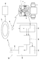
- FIG. 2 is a diagram showing a valve monitoring system using a fluid driven valve according to the present invention.
- FIG. 3 is a partially cutaway front view showing another embodiment of the fluid drive valve according to the present invention.
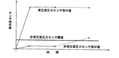
- FIG. 4 is a graph showing an example of a signal obtained from a pressure sensor of a fluid drive valve according to the present invention.
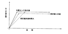
- FIG. 5 is a graph showing an example of a signal obtained from the position sensor of the fluid drive valve according to the present invention.
- Fluid operated valve 2 Body 3: Actuator 7: Casing 8: stem 9: Piston 11: Lower casing 12: Upper casing 17: Operation fluid introduction chamber 19: Non pressure receiving space 20: Sensor device 21: Pressure receiving surface pressure sensor 22: Non pressure receiving surface pressure sensor 23: Position sensor
- upper and lower and right and left mean upper and lower and right and left in FIGS. 1 and 3.
- the upper and lower sides and the left and right sides are for convenience, and the upper and lower sides may be reversed or the upper and lower sides may be used.
- FIG. 1 shows an embodiment of a fluid drive valve according to the present invention, wherein the fluid drive valve 1 comprises a body 2 provided with a fluid passage, and an actuator 3 for opening and closing the fluid passage by introducing or discharging an operating fluid. , And a sensor device 20 for detecting an abnormality of the fluid drive valve 1.
- Air is often used as the operation fluid, but various gases such as N 2 and Ar can be used.
- a valve body for opening and closing the fluid passage is provided in the body 2, and the fluid passage is opened and closed by being moved by the operation of the actuator 3.
- the left side of the body 2 is provided with an inlet joint 4 communicating with the fluid inflow passage, and the right side of the body 2 is provided with an outlet joint 5 communicating with the fluid outflow passage.
- a casing 7 is attached above the body 2 via a bonnet 6.
- the actuator 3 is disposed in the casing 7 and moves up or down to move the valve body in the opening or closing direction, the valve rod 8, the piston 9 integrally provided on the valve rod 8, and the valve rod 8 downward. And a compression coil spring (biasing member) 10 for biasing the same.
- the casing 7 comprises a lower casing 11 fixed to the bonnet 6 and an upper casing 12 screwed to the lower casing 11.
- the top wall of the upper casing 12 is formed with an internal thread 13 to which a pipe for introducing an operation fluid is connected.
- the piston 9 has a large diameter portion 9a which moves along the lower casing 11, an intermediate diameter portion 9b which is continuous with the upper surface of the large diameter portion 9a and whose outer diameter is smaller than the large diameter portion 9a, and is continuous with the upper surface of the intermediate diameter portion 9b. It consists of a small diameter portion 9c whose outer diameter is smaller than that of the middle diameter portion 9b.
- a cylindrical guide portion 14 is formed on the top wall of the upper casing 12 so as to be continuous with the lower side of the female screw portion 13, and the small diameter portion 9 c of the piston 9 moves along the guide portion 14. The guide portion 14 is fitted.
- An annular recess is provided on the outer periphery of the large diameter portion 9a, and an O ring 15 is disposed here for sealing between the outer peripheral surface of the lower casing 11 and the inner peripheral surface thereof.
- an annular recess is provided on the outer periphery of the small diameter portion 9c, and an O ring 16 that seals between the outer periphery and the inner peripheral surface of the guide portion 14 is disposed here.
- Operation fluid formed between the lower surface of the large diameter portion 9a of the piston 9 and the upper surface of the bottom wall of the lower casing 11 through the central portion of the small diameter portion 9c and the central portion of the intermediate diameter portion 9b
- An operation fluid passage 18 communicating with the introduction chamber 17 is formed.
- the compression coil spring 10 is received by an annular recess provided on the upper surface of the large diameter portion 9 a of the piston 9 and an annular recess provided on the lower surface of the top wall of the upper casing 12.
- the compression coil spring 10 biases the piston 9 downward, and the fluid passage is normally closed by moving the valve rod 8 downward. Then, when the operation fluid is introduced into the operation fluid introduction chamber 17, the piston 9 and the valve rod 8 are integrally moved upward, and the fluid passage can be opened.
- a non-pressure receiving space 19 Between the upper surface of the large diameter portion 9 a of the piston 9 and the lower surface of the top wall of the upper casing 12 is a non-pressure receiving space 19 into which the operation fluid does not enter.
- the sensor device 20 has two pressure sensors 21 and 22 and one position sensor 23.
- a first pressure sensor (hereinafter referred to as “pressure receiving surface pressure sensor”) 21 is provided on the lower surface of the large diameter portion 9a of the piston 9 so as to detect the pressure in the operation fluid introducing chamber 17, ie, the pressure receiving space.
- a second pressure sensor (hereinafter referred to as “non-pressure receiving surface pressure sensor”) 22 is provided on the upper surface of the large diameter portion 9 a of the piston 9 so as to detect the pressure of the non-pressure receiving space 19.
- the position sensor 23 is provided on the upper surface of the bottom wall of the lower casing 11 so as to detect the position (the distance from the position where the position sensor 23 is installed) of the lower surface of the large diameter portion 9 a of the piston 9.
- the pressure receiving surface pressure sensor 21 rises as the pressure in the operation fluid introducing chamber 17 rises, and the non-pressure receiving surface pressure sensor 22 becomes a non-pressure receiving space by the piston 9. As 19 is compressed, the pressure rises slightly.
- the position sensor 23 increases in value as the piston 9 moves upward. And while a fixed operation fluid is introduced, the indication value of each sensor 21, 22, 23 is maintained at the same value.
- FIG. 2 is a schematic view showing an embodiment of a monitoring system provided with the fluid driven valve 1 incorporating the above-mentioned sensors 21, 22, and 23, and the monitoring device 40. As shown in FIG.
- each fluid driven valve 1 is attached with an RFID which is one of the electronic tags in which the identification number is written.
- the RFID may be an active type with a built-in battery or a passive type without a battery. When the RFID is of a passive type, power can be supplied from the monitoring device 40 to the RFID by radio waves to be used as RFID power.
- the identification number of the fluid drive valve 1 is sent wirelessly from the RFID to the monitoring device 40, and the identification number is received by the receiving antenna 41 of the receiving unit 42 and temporarily stored in the determining unit 43.
- signals from the sensors 21, 22 and 23 of the fluid drive valve 1 enter the receiving unit 42 of the monitoring device 40 via the signal line (without the reference numeral) and are sent to the determining unit 43.
- signal transmission via wired signal lines wireless signal transmission may be used.
- the determination unit 43 determines whether the signal from the fluid drive valve 1 is a pass signal or a rejection signal, and the determination result and the identification number are stored in the storage unit 44 in pairs.
- the paired information can be displayed on the display unit (not shown) of the monitoring device 40 and confirmed.
- valve monitoring system can send the paired information to the sending unit 45, send a radio wave from the sending antenna 46 to the Internet network 47, and send it to the central management server 48.
- the centralized management server 48 performs identification management of all valves of a facility or a plant, and can immediately detect a valve in which an abnormality is recognized and can issue a warning.
- the sensor device 20 includes the pressure receiving surface pressure sensor 21, the non-pressure receiving surface pressure sensor 22, and the position sensor 23 so that the abnormality detection of the fluid drive valve 1 is performed using the signals obtained from these three sensors 21 22 23. It can be performed.
- the value of the non pressure receiving surface pressure sensor 22 is indicated by the broken line.
- the pressure gradually increases as shown it is considered that the operation fluid in the operation fluid introduction chamber 17 flows (leaks) into the non-pressure receiving space 19. Therefore, by setting a threshold for the non-pressure-receiving surface pressure sensor 22 and outputting an alarm when the threshold is exceeded, it is possible to detect in the initial leak and it is possible to detect an abnormality before a serious failure occurs. It can be detected.
- the importance of the abnormality is determined by comprehensively detecting what kind of state each of the signal of the pressure receiving surface pressure sensor 21, the signal of the non pressure receiving surface pressure sensor 22, and the signal of the position sensor 23 indicates. It is possible to understand the urgency of dealing with the degree and abnormalities, and to carry out early detection of abnormalities and early correspondence.
- the pressure receiving surface pressure sensor 21 for detecting the pressure of the operation fluid introducing chamber 17 may be provided on the upper surface of the bottom wall of the lower casing 11 and a non pressure receiving surface pressure for detecting the pressure of the non pressure receiving space 19.
- the sensor 22 may be provided on the inner peripheral surface of the peripheral wall of the upper casing 12 or may be provided on the lower surface of the top wall of the upper casing 12.
- the position sensor 23 may be provided on the lower surface or the upper surface of the large diameter portion 9 a of the piston 9 or on the inner peripheral surface of the peripheral wall of the lower casing 11 or on the lower surface of the top wall of the upper casing 12 It is also good.
- each sensor 21,22,23 can be installed in an appropriate place, one preferable example is shown in FIG.
- the pressure receiving surface pressure sensor 21 and the position sensor 23 are provided at positions facing the upper end surface of the valve rod 8 on the lower surface of the top wall of the upper casing 12, and the non pressure receiving surface pressure sensor 22 is the upper casing 12. It is provided in the position which faces the large diameter part 9a of piston 9 of the lower surface of the top wall. Since the valve rod 8 is a member that directly opens and closes the valve body, the accuracy can be improved by detecting the position of the valve rod 8 and the pressure acting on the valve rod 8. Although the pressure receiving surface pressure sensor 21 and the position sensor 23 can be provided on the upper end face of the valve rod 8, by providing all the sensors 21, 22, 23 in the upper casing 12, the installation of the sensors 21, 22, 23 is possible. It becomes easy.
- the number of pistons 9 is one, but may be plural.
- the piston 9 may be integral with or separate from the valve rod 8. As the number of the pistons 9 is increased, the number of the operating fluid introducing chambers 17 is increased, and the operating fluid is sent to each operating fluid introducing chamber.
- the fluid drive valve 1 described above is of a normally closed type in which the valve rod 8 is urged by the urging member 10 so that the valve rod 8 is always in the closed position, but the valve rod is always open by the urging member. Even in the case of the normally open type fluid driven valve which is biased as described above, the early abnormality detection is also a problem, and the above-mentioned sensor device 20 is also applied to the normally open type fluid driven valve.
- an abnormality in the fluid drive valve provided with an actuator for opening and closing the fluid passage by the introduction or discharge of the operation fluid, an abnormality can be detected at an early stage, so the safety of the device using this can be improved. Can contribute to
Landscapes
- Engineering & Computer Science (AREA)
- General Engineering & Computer Science (AREA)
- Mechanical Engineering (AREA)
- Physics & Mathematics (AREA)
- Fluid Mechanics (AREA)
- Indication Of The Valve Opening Or Closing Status (AREA)
- Fluid-Driven Valves (AREA)
- Fluid-Pressure Circuits (AREA)
Abstract
Description
2:ボディ
3:アクチュエータ
7:ケーシング
8:弁棒
9:ピストン
11:下部ケーシング
12:上部ケーシング
17:操作流体導入室
19:非受圧空間
20:センサ装置
21:受圧面圧力センサ
22:非受圧面圧力センサ
23:位置センサ
Claims (5)
- 流体通路が設けられたボディと、操作流体の導入又は排出によって前記流体通路を開閉するアクチュエータとを備えている流体駆動弁において、
前記操作流体の圧力が作用する前記アクチュエータ内部の受圧面および前記操作流体の圧力が作用しない前記アクチュエータ内部の非受圧面のそれぞれに圧力センサが設けられていることを特徴とする流体駆動弁。 - 前記操作流体の導入又は排出によって移動するピストンと、前記ピストンと一体に移動し弁体を開または閉方向に移動させる弁棒と、前記弁棒および前記ピストンを収納するケーシングとを備えており、前記弁棒または前記ピストンの位置を検知する位置センサがさらに設けられていることを特徴とする請求項1の流体駆動弁。
- 前記圧力センサは、前記ピストンの受圧面および前記ピストンの非受圧面に設けられている請求項2の流体駆動弁。
- 前記ケーシングは、前記ボディに固定された下部ケーシングと、前記下部ケーシングにねじ合わされた上部ケーシングとからなり、前記圧力センサが前記上部ケーシングの受圧面と非受圧面とにそれぞれ設けられていることを特徴とする請求項2の流体駆動弁。
- 前記位置センサが前記上部ケーシングに設けられて、弁棒の上端部に臨まされていることを特徴とする請求項4の流体駆動弁。
Priority Applications (5)
| Application Number | Priority Date | Filing Date | Title |
|---|---|---|---|
| KR1020197028556A KR102241057B1 (ko) | 2017-06-30 | 2018-06-22 | 유체 구동 밸브 |
| CN201880023021.1A CN110475999B (zh) | 2017-06-30 | 2018-06-22 | 流体驱动阀 |
| SG11201908174V SG11201908174VA (en) | 2017-06-30 | 2018-06-22 | Fluid drive valve |
| JP2019526856A JP7136469B2 (ja) | 2017-06-30 | 2018-06-22 | 流体駆動弁 |
| US16/497,047 US20210278012A1 (en) | 2017-06-30 | 2018-06-22 | Fluid drive valve |
Applications Claiming Priority (2)
| Application Number | Priority Date | Filing Date | Title |
|---|---|---|---|
| JP2017129667 | 2017-06-30 | ||
| JP2017-129667 | 2017-06-30 |
Publications (1)
| Publication Number | Publication Date |
|---|---|
| WO2019004071A1 true WO2019004071A1 (ja) | 2019-01-03 |
Family
ID=64741865
Family Applications (1)
| Application Number | Title | Priority Date | Filing Date |
|---|---|---|---|
| PCT/JP2018/023761 Ceased WO2019004071A1 (ja) | 2017-06-30 | 2018-06-22 | 流体駆動弁 |
Country Status (7)
| Country | Link |
|---|---|
| US (1) | US20210278012A1 (ja) |
| JP (1) | JP7136469B2 (ja) |
| KR (1) | KR102241057B1 (ja) |
| CN (1) | CN110475999B (ja) |
| SG (1) | SG11201908174VA (ja) |
| TW (1) | TW201907257A (ja) |
| WO (1) | WO2019004071A1 (ja) |
Cited By (1)
| Publication number | Priority date | Publication date | Assignee | Title |
|---|---|---|---|---|
| JP2020176689A (ja) * | 2019-04-19 | 2020-10-29 | 株式会社ブイテックス | ゲートバルブの制御方法 |
Families Citing this family (2)
| Publication number | Priority date | Publication date | Assignee | Title |
|---|---|---|---|---|
| KR102678050B1 (ko) * | 2022-06-09 | 2024-06-25 | 피케이밸브앤엔지니어링 주식회사 | 스윙 체크밸브 |
| JP2024079471A (ja) | 2022-11-30 | 2024-06-11 | 株式会社フジキン | バルブ制御装置、バルブ制御システム、バルブ制御方法、およびバルブ制御プログラム |
Citations (2)
| Publication number | Priority date | Publication date | Assignee | Title |
|---|---|---|---|---|
| JPH0449281U (ja) * | 1990-09-03 | 1992-04-27 | ||
| JP2016513228A (ja) * | 2013-02-25 | 2016-05-12 | レイヴ エヌ.ピー. インコーポレイテッド | スマート弁 |
Family Cites Families (10)
| Publication number | Priority date | Publication date | Assignee | Title |
|---|---|---|---|---|
| JP2001182850A (ja) * | 1999-12-24 | 2001-07-06 | Ckd Corp | 高温流体用切換弁 |
| JP2004092824A (ja) * | 2002-09-02 | 2004-03-25 | Fujikin Inc | 流体制御器 |
| JP5399687B2 (ja) | 2008-11-14 | 2014-01-29 | 関東化学株式会社 | エアオペレートバルブ診断方法及びエアオペレートバルブ |
| GB2510519B (en) * | 2009-10-09 | 2014-09-24 | Cameron Int Corp | Valve utilizing a force sensor |
| US8814133B2 (en) * | 2011-06-23 | 2014-08-26 | General Equipment And Manufacturing Company, Inc. | Automatic speed searching device and method for a partial stroke test of a control valve |
| JP5945499B2 (ja) * | 2012-11-30 | 2016-07-05 | Ckd株式会社 | 流体制御弁 |
| CN203604777U (zh) * | 2013-11-25 | 2014-05-21 | 江苏远望仪器有限公司 | 设有故障反馈结构的阀门液压执行器 |
| JP6588207B2 (ja) * | 2014-12-26 | 2019-10-09 | 株式会社フジキン | バルブ |
| CN104565506B (zh) * | 2015-01-14 | 2017-06-09 | 重庆川仪自动化股份有限公司 | 阀门用双动力集成防爆电液执行机构 |
| CN205745578U (zh) * | 2016-06-23 | 2016-11-30 | 浙江嘉隆机械设备有限公司 | 紧急切断罐底阀 |
-
2018
- 2018-06-22 US US16/497,047 patent/US20210278012A1/en not_active Abandoned
- 2018-06-22 KR KR1020197028556A patent/KR102241057B1/ko not_active Expired - Fee Related
- 2018-06-22 WO PCT/JP2018/023761 patent/WO2019004071A1/ja not_active Ceased
- 2018-06-22 CN CN201880023021.1A patent/CN110475999B/zh not_active Expired - Fee Related
- 2018-06-22 SG SG11201908174V patent/SG11201908174VA/en unknown
- 2018-06-22 JP JP2019526856A patent/JP7136469B2/ja active Active
- 2018-06-29 TW TW107122476A patent/TW201907257A/zh unknown
Patent Citations (2)
| Publication number | Priority date | Publication date | Assignee | Title |
|---|---|---|---|---|
| JPH0449281U (ja) * | 1990-09-03 | 1992-04-27 | ||
| JP2016513228A (ja) * | 2013-02-25 | 2016-05-12 | レイヴ エヌ.ピー. インコーポレイテッド | スマート弁 |
Cited By (1)
| Publication number | Priority date | Publication date | Assignee | Title |
|---|---|---|---|---|
| JP2020176689A (ja) * | 2019-04-19 | 2020-10-29 | 株式会社ブイテックス | ゲートバルブの制御方法 |
Also Published As
| Publication number | Publication date |
|---|---|
| KR20190122774A (ko) | 2019-10-30 |
| CN110475999B (zh) | 2021-04-06 |
| JP7136469B2 (ja) | 2022-09-13 |
| JPWO2019004071A1 (ja) | 2020-05-07 |
| US20210278012A1 (en) | 2021-09-09 |
| SG11201908174VA (en) | 2019-10-30 |
| CN110475999A (zh) | 2019-11-19 |
| KR102241057B1 (ko) | 2021-04-16 |
| TW201907257A (zh) | 2019-02-16 |
Similar Documents
| Publication | Publication Date | Title |
|---|---|---|
| US8768631B2 (en) | Diagnostic method for detecting control valve component failure | |
| KR101915638B1 (ko) | 다채널 밸브제어 및 자가고장 진단 시스템 | |
| TWI687658B (zh) | 流體控制器的異常檢測裝置、異常檢測系統、異常檢測方法及流體控制器 | |
| CN102472408A (zh) | 用于确定气动式控制阀组件的故障模式的装置与方法 | |
| US11174965B2 (en) | Detecting maintenance statuses of valves | |
| EP2949950B1 (en) | Cylinder device | |
| WO2019004071A1 (ja) | 流体駆動弁 | |
| KR102735921B1 (ko) | 공압팽창밸브 제어 시스템 | |
| CN108474707B (zh) | 用于防爆的超压包封系统和相应的操作方法 | |
| JP6945932B2 (ja) | 漏水検知装置 | |
| US9915581B2 (en) | Seal detecting device and means thereof | |
| EP4726239A1 (en) | Smart valve monitoring system and method | |
| CN118257905A (zh) | 用于检测隔膜漏气的检测器、调节阀装置和检测方法 |
Legal Events
| Date | Code | Title | Description |
|---|---|---|---|
| 121 | Ep: the epo has been informed by wipo that ep was designated in this application |
Ref document number: 18823469 Country of ref document: EP Kind code of ref document: A1 |
|
| ENP | Entry into the national phase |
Ref document number: 20197028556 Country of ref document: KR Kind code of ref document: A |
|
| ENP | Entry into the national phase |
Ref document number: 2019526856 Country of ref document: JP Kind code of ref document: A |
|
| NENP | Non-entry into the national phase |
Ref country code: DE |
|
| 122 | Ep: pct application non-entry in european phase |
Ref document number: 18823469 Country of ref document: EP Kind code of ref document: A1 |