WO2019001532A1 - Vehicle body structure and vehicle - Google Patents
Vehicle body structure and vehicle Download PDFInfo
- Publication number
- WO2019001532A1 WO2019001532A1 PCT/CN2018/093441 CN2018093441W WO2019001532A1 WO 2019001532 A1 WO2019001532 A1 WO 2019001532A1 CN 2018093441 W CN2018093441 W CN 2018093441W WO 2019001532 A1 WO2019001532 A1 WO 2019001532A1
- Authority
- WO
- WIPO (PCT)
- Prior art keywords
- section
- vehicle body
- body structure
- cross member
- floor
- Prior art date
- Legal status (The legal status is an assumption and is not a legal conclusion. Google has not performed a legal analysis and makes no representation as to the accuracy of the status listed.)
- Ceased
Links
Images




Classifications
-
- B—PERFORMING OPERATIONS; TRANSPORTING
- B62—LAND VEHICLES FOR TRAVELLING OTHERWISE THAN ON RAILS
- B62D—MOTOR VEHICLES; TRAILERS
- B62D25/00—Superstructure or monocoque structure sub-units; Parts or details thereof not otherwise provided for
- B62D25/20—Floors or bottom sub-units
-
- B—PERFORMING OPERATIONS; TRANSPORTING
- B62—LAND VEHICLES FOR TRAVELLING OTHERWISE THAN ON RAILS
- B62D—MOTOR VEHICLES; TRAILERS
- B62D21/00—Understructures, i.e. chassis frame on which a vehicle body may be mounted
- B62D21/02—Understructures, i.e. chassis frame on which a vehicle body may be mounted comprising longitudinally or transversely arranged frame members
-
- B—PERFORMING OPERATIONS; TRANSPORTING
- B62—LAND VEHICLES FOR TRAVELLING OTHERWISE THAN ON RAILS
- B62D—MOTOR VEHICLES; TRAILERS
- B62D25/00—Superstructure or monocoque structure sub-units; Parts or details thereof not otherwise provided for
- B62D25/08—Front or rear portions
Definitions
- the present disclosure relates to a vehicle body structure, and to a vehicle having the vehicle body structure.
- the present disclosure provides a vehicle body structure including two front side members spaced apart in the left-right direction, two floor longitudinal members spaced apart in the left-right direction, and two rear side members spaced apart in the left-right direction. And a front cross member, wherein when the vehicle body structure is subjected to a front or rear collision, the impact force is correspondingly transmitted in the forward or reverse direction in the following order: the front longitudinal beam - the front cross member - the floor longitudinal beam - the Rear longitudinal beam.
- the body structure of the present disclosure can better achieve the collision force transmission and dispersion when subjected to the front or rear collision, thereby reducing the deformation of the vehicle body structure and reducing the damage that the occupant may be subjected to.
- the present disclosure also provides a vehicle including the vehicle body structure as described above.
- FIG. 1 is a bottom perspective view of a partial structure of a vehicle body structure provided by the present disclosure, showing a front side rail, a front cross member, a front cross member, a dash panel, and a floor panel;
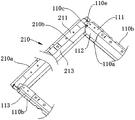
- FIG. 2 is a perspective view of a front cross member in a vehicle body structure provided by the present disclosure
- FIG. 3 is a schematic view showing a connection relationship between a front side rail and a front cross member in a vehicle body structure provided by the present disclosure
- FIG. 4 is a detailed view of a connection relationship between a front side rail and a front cross member in a vehicle body structure provided by the present disclosure
- FIG. 5 is a schematic view showing a connection relationship between a front side rail, a front side cross member and a front cross member in a vehicle body structure provided by the present disclosure
- FIG. 6 is a schematic view showing a positional relationship between a front cabin beam and a front longitudinal beam in a vehicle body structure provided by the present disclosure
- Figure 7 is a detailed view of the connection relationship between the front side member and the front cabin beam in a vehicle body structure provided by the present disclosure
- Figure 8 is a perspective view showing another partial structure of a vehicle body structure provided by the present disclosure, showing an inner connecting plate and an outer connecting plate;
- FIG. 9 is a detailed view showing a connection relationship between an inner connecting plate and other components of the vehicle body structure in a vehicle body structure provided by the present disclosure.
- FIG. 10 is a detailed view showing a connection relationship between an outer connecting plate and other components of the vehicle body structure in a vehicle body structure provided by the present disclosure
- Figure 11 is a perspective view showing still another partial structure of a vehicle body structure provided by the present disclosure, showing a floor stringer, a rear side member and a floor rear cross member;
- Figure 12 is a bottom plan view showing still another partial structure of a vehicle body structure provided by the present disclosure.
- FIG. 13 is a schematic view of a carrier frame in a vehicle body structure provided by the present disclosure.
- FIG. 14 is another schematic view of a carrier frame in a vehicle body structure provided by the present disclosure, in which a battery tray is shown;
- FIG. 15 is still another schematic view of a carrier frame in a vehicle body structure provided by the present disclosure, wherein the battery tray is formed into a split structure;
- FIG. 16 to FIG. 20 are schematic diagrams showing a first connection manner of a front cross member, a sill inner panel, and a floor longitudinal member in a vehicle body structure provided by the present disclosure
- FIG. 21 and FIG. 22 are schematic diagrams showing a second connection manner of a front cross member, a sill inner panel, and a floor rail in a vehicle body structure provided by the present disclosure
- FIG. 23 is a detailed view showing a connection relationship between a front side member, a front cross member, a floor side member, and a reinforcing beam of the first embodiment in a vehicle body structure provided by the present disclosure
- Figure 24 is a detailed view showing the connection relationship of the front side member, the front cross member, the floor side member and the reinforcing beam of the second embodiment in a vehicle body structure provided by the present disclosure
- 25 is a detailed view of a connection relationship between a floor rear cross member and a rear side member in a vehicle body structure provided by the present disclosure
- 26 is a detailed view of a connection relationship between a floor longitudinal beam and a rear longitudinal beam in a vehicle body structure provided by the present disclosure
- Figure 27 is a bottom plan view showing a partial structure of another vehicle body structure provided by the present disclosure.
- 29 is a partial structural bottom view of a vehicle body structure provided by the present disclosure, showing a reinforcing beam and a reinforcing stringer;
- FIG. 30 is a top perspective view of a partial structure of a vehicle body structure provided by the present disclosure, showing a side wall;
- 31 is a top plan view showing a partial structure of a vehicle body structure provided by the present disclosure.
- 32 is a bottom plan view showing a partial structure of a vehicle body structure provided by the present disclosure.
- 33 is a partial structural exploded view of a vehicle body structure provided by the present disclosure.
- Figure 34 is a perspective view of a reinforcing stringer in a vehicle body structure provided by the present disclosure.
- 35 is an exploded view of a reinforcing stringer in a vehicle body structure provided by the present disclosure.
- 36 is a perspective view of an upper beam section in a vehicle body structure provided by the present disclosure.
- FIG. 37 is a perspective view of a lower beam section in a vehicle body structure provided by the present disclosure.
- FIG. 38 is a perspective view of a rear reinforcing beam in a vehicle body structure provided by the present disclosure.
- 39 is a detailed view of a connection relationship between a reinforcing longitudinal beam and a reinforcing beam in a vehicle body structure provided by the present disclosure.
- FIG. 40 is a perspective view of a floor panel in a vehicle body structure provided by the present disclosure.
- Figure 41 is a cross-sectional view taken along line A-A of Figure 31;
- Figure 42 is an enlarged view of a portion C in Figure 41;
- Figure 43 is a partial enlarged view of Figure 42;
- Figure 44 is a cross-sectional view taken along line B-B of Figure 31;
- Figure 45 is an enlarged view of a portion D in Figure 44;
- Figure 46 is a perspective view, partly in section, of the vehicle body structure taken from the vicinity of the front reinforcing beam;
- 47 is a schematic view showing the arrangement position of a motor, an electric control device, and a battery pack in a vehicle body structure provided by the present disclosure
- FIG. 48 is an exploded view of a rear partial structure of a vehicle body structure provided by the present disclosure.
- FIG. 49 is a perspective view of a rear section of a rear side member in a vehicle body structure provided by the present disclosure.
- Figure 50 is a top plan view of a rear partial structure of a vehicle body structure provided by the present disclosure.
- Figure 51 is a bottom plan view of a rear partial structure of a vehicle body structure provided by the present disclosure.
- Figure 52 is a cross-sectional view taken along line E-E of Figure 51;
- Figure 53 is an enlarged view of a portion G in Figure 52;
- Figure 54 is a sectional view taken along line F-F of Figure 51;
- Figure 55 is an enlarged view of a portion H in Figure 54;
- Figure 56 is an exploded view of another rear partial structure of a vehicle body structure provided by the present disclosure.
- 57 is a rear partial structural side view of a vehicle body structure provided by the present disclosure.
- Figure 58 is a front elevational view of the rear motor impact beam in a vehicle body structure provided by the present disclosure.
- FIG. 59 is another exploded partial structural exploded view of a vehicle body structure provided by the present disclosure.
- Figure 60 is another rear partial structural side view of a vehicle body structure provided by the present disclosure.
- 61 is a perspective view of a guide beam and a front mounting beam in a vehicle body structure provided by the present disclosure
- 62 is a bottom view of a vehicle body structure provided by the present disclosure.
- the orientation words used are defined on the basis of the up and down direction, the left and right direction, and the front and rear direction of the vehicle, unless otherwise stated.
- the X direction is the front and rear direction of the vehicle, that is, the longitudinal direction of the vehicle, wherein the side pointed by the arrow is “front”, and vice versa is “rear”
- the Y direction is the left and right direction of the vehicle, that is, the vehicle Lateral, wherein the side pointed by the arrow is "right”, and vice versa is “left”
- the Z direction is the up and down direction of the vehicle, that is, the height direction of the vehicle, wherein the side pointed by the arrow is “up” and vice versa
- “Inside and outside” are defined based on the contours of the corresponding components, such as the interior and exterior of the vehicle, which are defined on the basis of the vehicle's contour, and the inner side near the center of the vehicle is "inside”
- All “beams” in this disclosure refer to beams that extend generally in the left and right direction of the vehicle, and all “stringers” refer to beams that extend generally in the fore and aft direction of the vehicle.
- the "front stringer” refers to a stringer that extends rearward from the front anti-collision beam of the vehicle body structure.
- “Back stringer” refers to a stringer that extends forward from the rear crash beam of the vehicle in the body structure.
- connection is to be understood broadly, and may be in a non-removable manner such as welding, a detachable manner such as a bolt, or the like, unless otherwise explicitly stated and defined.
- the system is realized in a one-piece manner.
- FIGS. 1-10 A vehicle body structure of a vehicle according to an embodiment of the present disclosure will be described below with reference to FIGS.
- the present disclosure provides a vehicle body structure, as shown in FIG. 1, which may include two front side members 100, a front cross member 210, and a floor panel 300 spaced apart in the left-right direction.
- the front panel of the floor panel 300 is connected to a dash panel 320, and the passenger compartment of the vehicle is defined behind the dash panel 320 and above the floor panel 300.
- the front cross member 210 is fixed to the lower surface of the floor panel 300 and the rear end of the front side member 100 is coupled to the front cross member 210, that is, the front side member 100 is cut off from the front cross member 210, thereby causing a frontal collision in the vehicle ( At the front touch, a support for the rear end of the front side member 100 is formed, thereby dispersing the collision impact force transmitted by the front side member 100, and avoiding deformation of the rear side member 100 to invade the passenger compartment.
- the front cross member 210 can be disposed adjacent to the dash panel 320.
- the fixed connection of the front cross member 210 to the lower surface of the floor panel 300 can function to reinforce the floor panel 300, and avoid excessive deformation, folding, etc.
- the width of the front side member 100 in the left-right direction is greatest at the junction with the front cross member 210, that is, the front side member 100 may be gradually widened toward the front cross member, and the front cross member 210 can be made through a larger joint width.
- the front side member 100 can be overlapped more stably.
- the front beam 210 is disposed in front of the battery pack to absorb impact energy and reduce impact impact on the battery pack. Squeeze and protect the battery pack.
- the front cross member 210 is formed as an upwardly open groove-like structure, and includes a front cross member bottom wall 211, an opposite front cross member front side wall 212, and a front cross member rear side.
- the upper edge of the front cross member front side wall 212 is formed with a front cross member front side wall flange 210a extending in the left-right direction
- the upper edge of the front cross member rear side wall 213 is formed with a front cross member rear side wall extending in the left-right direction.
- the side cross member 210 is joined to the lower surface of the floor panel 300 by a front cross member front side wall flange 210a and a front cross member rear side wall flange 210b.
- the front cross member 210 and the floor panel 300 enclose a cavity having a generally rectangular or trapezoidal cross section to enhance the collision resistance of the vehicle body structure and help to reduce the collision deformation of the floor panel 300.
- a reinforcing structure for example, welding sheet metal
- a CBS composite reinforcing material
- the front end of the front cross member front side wall 212 may be formed with a front cross member front side wall end flange 210c, and the front end of the front cross member rear side wall 213 may be formed with a front cross member rear side end flange.
- the end of the front beam bottom wall 211 may extend outward to form a front beam bottom wall overlapping edge 210e, so that the front beam 210 can pass the front beam front side end flange 210c, the front beam rear side end
- the flange 210d and the front beam bottom wall overlapping edge 210e overlap with other components of the vehicle body structure, such as the floor rail 110 or the sill inner panel 500 mentioned below.
- the front side member 100 can be coupled to the front cross member 210 by any suitable means.
- the front side member 100 can be respectively associated with the front cross member bottom wall. 211.
- the front cross member front side wall 212 and the front cross member front side wall flanks 210a are overlapped.
- the rear section of the front side member 100 may be formed as an upwardly open groove-like structure, and includes a front longitudinal beam bottom wall 101 and oppositely disposed front side member inner side walls 102 and front longitudinals.
- An upper edge of the front side wall 102 is formed with a front side rail inner side flange 100a extending in the front-rear direction
- an upper edge of the front side rail outer side wall 103 is formed with a front side rail outer side wall flange 100b extending in the front-rear direction.
- the rear side of the front side wall 102 is formed with a front side member inner side end flange 100c, and the rear side of the front side wall 103 is formed with a front side member outer side end flange 100d, and the front side member bottom wall 101 The rear end extends rearwardly to form a front side rail bottom wall lap edge 100e.
- the front side frame inner side wall flange 100a overlaps the front beam front side wall flange 210a
- the front side beam outer side wall flange 100b overlaps with the front beam front side wall flange 210a.
- the inner side end flange 100c of the beam overlaps the front cross member front side wall 212
- the front side outer wall end flange 100d overlaps the front cross member front side wall 212
- the front side member bottom wall overlaps the side 100e and the front cross member
- the bottom wall 211 is overlapped.
- the front side member 100 is formed with a concave point 105 for avoiding the wheel along the wheel envelope.
- the inner side of the front side member 100 corresponds to the concave point 105.
- the location can be connected to a stiffener.
- a front cabin cross member 220 may be connected between the two front side rails 100.
- the front cabin cross member 220 is disposed in front of the dash panel 320 and may be connected to the dash panel 320 for use.
- the front part of the vehicle is moved rearwardly and can also function to reinforce the dash panel 320 such that the dash panel 320 is less susceptible to collisional deformation.
- the front bulkhead 220, the two front longitudinal beams 100, and the front cross member 210 can enclose a closed-loop frame structure, so that the strength of the body structure of the portion is higher, and can withstand large initial collision loads and front parts of the vehicle.
- the impact is reversed and the front cowl 220 and the front beam 210 can be used to transmit force to reduce frontal deformation of the vehicle, protecting the occupant and vehicle components, such as battery packs, disposed behind the front cross member 210.
- the front bulkhead 220 can be attached to the inner recess 105 of the front side member 100 to form support for the front side member 100 to prevent the front side member 100 from being bent.
- the orthographic projection of the front end of the front side member 100 on the horizontal plane and the orthographic projection of the rear end of the front side member 100 on the horizontal plane are offset by a distance of no more than 80 mm in the left-right direction. That is, the front end of the front side member 100 is projected on the horizontal plane in the Z direction, and the projection of the rear end of the front side member 100 in the horizontal direction along the Z direction is shifted by a distance of not more than 80 mm in the Y direction, so that the front side member 100 is as far as possible. Close to the straight beam for better force transmission.
- the front bulkhead 220 can be coupled between the two front side members 100 in any suitable manner.
- the front bulkhead beam 220 is formed as an upwardly open groove-like structure, and includes a front cabin beam bottom wall 221 and a relative front
- the cabin beam front side wall 222 and the front cabin beam rear side wall 223, the upper edge of the front cabin beam front side wall 222 is formed with a front cabin beam front side wall flange 220a extending in the left-right direction, and a front cabin beam rear side wall 223
- the upper edge is formed with a front side cross member rear side wall flange 220b extending in the left-right direction, and an end portion of the front cabin beam front side wall 222 is formed with a front cabin beam front side wall end flange 220c, and a front cabin beam rear side wall 223
- the end portion is formed with a front side cross member rear side wall end flange 220d, and an end portion
- the front cabin beam front side flange 220a and the front cabin beam rear side flange 220b overlap with the front longitudinal beam inner side flange 100a, the front cabin beam front side end flange 220c and the front cabin beam rear side
- the wall end flange 220d overlaps the front longitudinal beam inner side wall 102, and the front cabin beam bottom wall overlapping edge 220e overlaps the front longitudinal beam bottom wall 101.
- the flanges or overlapping edges and the front side members 100 may be connected and welded to improve the connection strength between the front cabin beam 220 and the front longitudinal beam 100, thereby ensuring that the front cabin beam 220 can be compared.
- the vehicle's power unit such as the motor or engine
- the front cabin beam 220 can be formed in a segmented configuration for ease of fabrication.
- the front cabin beam 220 may include a beam body and an end connecting section connected to both ends of the beam body.
- the opening width of the groove structure of the front bulkhead 220 is gradually increased along the beam body to the end connecting section, thereby facilitating processing and front side members. 100 laps of each cuff.
- the front bulkhead 220 can also be formed as a unitary structure.
- the front side member 100 can have a body section 100A and a downwardly curved section 100B attached to the rear end of the body section 100A.
- the front cabin beam 220 is mounted to the downwardly curved section of the two front side members 100. 100B, and at least partially below the body segment 100A (refer to Figure 6).
- the main section 100A of the front side member is generally higher than the floor panel 300 of the vehicle passenger compartment, and the transition of the front side member in the up and down direction is achieved by the downwardly curved section.
- the main body segment 100A can be used for vehicle power devices such as motors and engines. These vehicle powerplants are typically located at least partially below the body segment 100A.
- the front side member 100 collapses to drive the vehicle component mounted on the main body section 100A to move rearward, and the front bulkhead beam 220 mounted on the downwardly curved section 100B is only partially located below the main body section 100A.
- the vehicle component that moves backwards such as a vehicle power device such as a motor, can be stopped to prevent the passenger from invading the vehicle cabin due to a collision impact, thereby protecting the occupant.
- the main body section 100A is provided with a mounting point for mounting the front sub-frame, and the power device of the vehicle is mounted on the main body section 100A through the front sub-frame, and is at least partially disposed below the main body section 100A and the front cabin beam
- the front of the 220 is such that the front cabin beam 220 can stop the power unit from moving backwards in the event of a frontal collision and threaten the passenger compartment.
- the front bulkhead 220 is at least partially coupled to the bottom of the downwardly curved section 100B.
- the vehicle body structure may further include an inner connecting plate 410 and an outer connecting plate 420 or one of them to enable reinforcement and rearing of the front side member 100.
- the inner connecting plate 410 is coupled to the inner side of the front side rail 100 and is located between the front bulkhead 220 and the front cross member 210.
- the inner connecting plate 410 may also be coupled to at least one of the front bulkhead 220 and the front cross member 210. In this way, the inner connecting plate 410 can also assist in dispersing the collision impact force, avoiding excessive bending of the rear section of the front side frame 100, causing the dash panel 320 to deform and squeezing the passenger compartment space.
- the inner connecting plate 410 may include an inner connecting bottom wall 411 having a first edge of the inner connecting plate sequentially connected end to end, a second edge of the inner connecting plate, a third edge of the inner connecting plate and the inner side a fourth edge of the connecting plate, a first edge of the inner connecting plate extends along the front cross member 210 and overlaps the front cross member 210, and a second edge of the inner connecting plate extends along the front longitudinal beam 100 and overlaps the front longitudinal beam 100 due to the front
- the cabin beam 220 is located above the front cross member 210 in the up and down direction, and the first inner connecting side wall 412 extending upwardly at an angle is connected to the third edge of the inner connecting plate to accommodate the up and down direction of the front hatch beam 220 and the front cross member 210.
- the first inner connecting side wall 412 is overlapped with the front side cross member 220, and the fourth inner side of the inner connecting plate is connected with an upwardly extending second inner connecting side wall 413.
- the second inner connecting side wall 413 is overlapped with the front cross member 210. .
- the first edge of the inner connecting plate extends outward to form an inner connecting plate first overlapping surface 410a extending in the left-right direction, and the upper edge of the second inner connecting side wall 413 is folded outward to form an edge.
- a first inner connecting side wall first flange 410b extending in the front-rear direction, and an end of the second inner connecting side wall 413 adjacent to the first edge of the inner connecting plate is folded outward to form a second inner connecting side wall extending in the up-and-down direction
- the second flange 410c among them:
- the first connecting edge 410a of the inner connecting plate overlaps with the front beam bottom wall 211, the first inner connecting side wall first flange 410b overlaps the front beam front side wall flange 210a, and the second inner connecting side wall 2nd turns
- the side 410c is overlapped with the front cross member front side wall 212;
- the second edge of the inner connecting plate extends outward to form an inner connecting plate second overlapping edge 410d, and the inner connecting plate second overlapping edge 410d overlaps the longitudinal beam bottom wall 103;
- the upper edge of the first inner connecting sidewall 412 is outwardly folded to form a first inner connecting sidewall flange 410e, and the first inner connecting sidewall flange 410e overlaps the front cabin beam 220.
- the inner connecting plate 410 can also be provided with a reinforcing structure by welding a sheet metal or the like, thereby further strengthening the strength of the rear portion of the front side frame 100, and preventing the rear portion of the front side frame 100 from invading the dash panel 320 due to collision and bending.
- the outer connecting plate 420 is disposed on the outer side of the front side member 100, and can be coupled to the front side member 100 and the front cross member 210 to function to reinforce the front side member 100, and is also applicable to In the case of a small offset collision of the vehicle, that is, the impact occurs on the outer side of the front longitudinal beam 100. At this time, the force of the front longitudinal beam 100 is small, and the effect of the collapse energy absorption is poor, and the wheel is subjected to impact and the vehicle is pressed backward.
- the A-pillar and the dash panel 320 easily cause deformation of the vehicle body structure and squeeze the passenger compartment.
- the outer connecting plate 420 Since the outer connecting plate 420 is located outside the front longitudinal beam 100 and overlaps the front longitudinal beam 100 and the front cross member 210, respectively, the outer connecting plate 420 can withstand the wheel impact and the front longitudinal beam 100 and the front in a small offset collision.
- the beam 210 transmits force.
- the outer connecting plate 420 can also extend outward to overlap the sill inner panel 500, so that the force of the small offset collision can also be transmitted to the rear of the vehicle through the sill inner panel 500 to reduce The deformation of the vehicle A-pillar and the dash panel 320 caused by the collision impact.
- the sill inner panel 500 is disposed on the left and right sides of the floor panel 300, and the front end of the sill inner panel 500 can protrude forwardly from the front cross member 210. As shown in FIG. 20, the front end of the sill inner panel 500 and the front cross member 210 are in the front-rear direction.
- the distance may be less than 1000 mm, for example may be 30-200 mm, preferably may be 60-140 mm.
- the outer connecting plate 420 may include an outer connecting bottom wall 421 formed in a quadrangular shape, and having a first edge of the outer connecting plate sequentially connected end to end, and a second edge of the outer connecting plate a third edge of the outer connecting plate and a fourth edge of the outer connecting plate, wherein the first edge of the outer connecting plate extends along the front beam 210 and overlaps the front beam 210, and the second edge of the outer connecting plate extends along the front longitudinal beam 100 Attached to the front side member 100, the outer edge of the outer connecting plate is connected with an upwardly extending outer connecting side wall 422, and the outer connecting side wall 422 is also overlapped with the front side frame 100, and the fourth edge of the outer connecting plate
- the sill inner panel 500 extends and overlaps the sill inner panel 500.
- the first edge of the outer connecting plate extends outward to form a first connecting edge 420a of the outer connecting plate extending in the left-right direction, and the first connecting edge 420a of the outer connecting plate overlaps with the front beam bottom wall 211;
- the second edge of the board extends outward to form a second overlapping edge 420b of the outer connecting plate extending in the front-rear direction, and the upper edge of the outer connecting side wall 422 is folded outward to form the outer connecting side wall first flange 420c, and the outer connecting
- the side wall 422 is folded outwardly near the end of the second edge of the outer connecting plate to form an outer connecting side wall second flange 420d extending in the up and down direction, wherein the outer connecting plate second overlapping edge 420b and the front longitudinal beam bottom
- the outer wall side flange 420c overlaps the front side frame outer side wall flange 100b;
- the outer connecting side wall second flange 420d overlaps the front side member outer side wall 103;
- the outer connecting plate 420 is formed substantially in a trapezoidal structure, wherein the length of the second edge of the outer connecting plate is greater than the length of the fourth edge of the outer connecting plate, and the outer connecting plate is third.
- the edge transitions between the second edge of the outer web and the fourth edge of the outer web to avoid the wheel. Therefore, in the front collision, the outer connecting plate 420 can disperse the collision impact force concentrated on the rear portion of the front side frame 100 to the rear of the sill inner panel 500 and the vehicle body structure to reduce the collision of the rear section of the front side member 100.
- the crushing strength, and the trapezoidal structure of the outer connecting plate 420 allows the front side member 100 to have better lateral stability and is not easily bent.
- the outer connecting plate 420 is further provided with a reinforcing structure for carrying the force in the front-rear direction.
- the reinforcing structure may be formed as a reinforcing rib extending from the first edge of the outer connecting plate toward the third edge of the outer connecting plate, and the projection of the wheel on the outer connecting plate 420 in the front-rear direction at least partially coincides with the end of the reinforcing rib,
- the reinforcing structure may alternatively be formed as sheet metal or filled CBS (composite reinforcing material).
- the vehicle body structure may further include two vehicle body longitudinal beams disposed at right and left intervals and two rear side members 120 spaced apart from each other, the rear of the vehicle body longitudinal beam The end is connected to the two rear side members 120, and the front cross member 210 can be coupled to the longitudinal beam of the vehicle body to transmit the impact impact force generated during the front collision to the rear portion of the vehicle body structure to reduce the deformation of the front portion of the vehicle. Moreover, in this way, it is also possible to transmit the collision impact force generated at the time of the rear collision to the front portion of the vehicle body structure, and to reduce the deformation of the rear portion of the vehicle body.
- the body longitudinal beam and the rear side member 120 are connected to each other to increase the strength of the vehicle body structure.
- the vehicle body structure may further include a floor rear cross member 230 spaced apart from the front cross member 210 and connected to the lower surface of the floor panel 300. Both ends of the floor rear cross member 230 may be respectively connected to the two longitudinal members of the vehicle body, or may be connected to the two rear side members 120, respectively.
- the carrier frame 700 can be used to mount and carry vehicle components, such as a battery tray 610 (visible in Figure 14) for mounting and carrying a battery pack.
- the rear side members 120 are divided into a front portion located in front of the floor rear cross member 230 and a rear portion behind the floor rear cross member 230 for convenience of explanation.
- the front cross member 210, the two body longitudinal beams, the front portions of the two rear side members 120, and the floor rear cross member 230 collectively enclose a carrier frame 700 that can be used to mount and carry vehicle components, such as A battery tray 610 for mounting and carrying a battery pack.
- the battery can be arranged as much as possible under the floor panel 300, which is beneficial to ensure that the vehicle has the longest possible cruising distance.
- the front cross member 210 and the floor rear cross member 230 may be sequentially referred to as a battery pack front mounting beam and a battery pack rear mounting beam, a front cross member 210, a floor rear cross member 230, and the vehicle body longitudinal direction.
- a battery tray fastening hole may be opened in the beam to mount the battery tray 610 carrying the battery pack to the front cross member 210, the floor rear cross member 230, and the longitudinal beam of the vehicle body by fasteners.
- the battery pack may be mounted on the carrier frame in a unitary form or may be mounted on the carrier frame 700 in a split form.
- the battery tray 610 may be one or plural.
- the load-bearing frame 700 can be divided by adding a cross beam 360 in one or more battery packs between the front cross member 210 and the floor rear cross member 230.
- the battery tray of each battery pack can be mounted on the corresponding sub-frame.
- a battery tray fastening hole may be opened in the mounting beam 360 of the battery pack.
- the mounting beam 360 in the battery pack may be disposed on the lower surface of the floor panel 300 or on the upper surface of the floor panel 300.
- a hole may be opened at a corresponding position on the floor panel 300 so that the fastener can pass through the floor panel 300 to be connected to the mounting beam 360 in the battery pack.
- the cross member 360 in the battery pack may be replaced by a cross member inherent to the vehicle body structure, such as a front seat mounting cross member.
- the battery tray 610 includes a first sub-tray 610A and a second sub-tray 610B that are separately disposed, and a battery pack is disposed between the front cross member 210 and the floor rear cross member 230.
- the cross member 360, the first sub-tray 610A is connected to the front cross member 210, the floor rail 110 and the battery pack mounting cross member 360, respectively, and the second sub-tray 610B is respectively mounted with the cross member 360, the floor rail 110 and the floor rear cross member 230 in the battery pack. connection.
- the vehicle body longitudinal beam may be a beam inherent to the vehicle body structure (for example, the sill inner panel 500), or may be a beam specially provided for mounting the battery tray 610.
- the body longitudinal beam may be a sill inner panel 500, and the two sill inner panels 500 are respectively disposed on the left and right sides of the floor panel 300.
- a battery tray fastening hole may be opened in the sill inner panel 500.
- the vehicle body longitudinal beam may be a floor rail 110 connected to the lower surface of the floor panel 300, and the floor rail 110 may be connected to the sill inner panel 500 or may be spaced from the sill inner panel 500.
- a battery tray fastening hole may be opened in the floor rail 110, and the floor rail 110 may be referred to as a battery pack mounting stringer.
- the body longitudinal beam may be an assembly including a sill inner panel 500 and a floor rail 110 that is coupled to the sill inner panel 500.
- the front cross member 210 may be coupled to one or both of the floor rail 110 and the sill inner panel 500, and the floor rail 110 and the sill inner panel 500 may each be provided with a battery tray fastening hole, and
- the floor rail 110 can be referred to as a battery pack mounting stringer.
- the longitudinal beam of the vehicle body is the floor longitudinal beam 110
- the floor longitudinal beam 110 as a first possible embodiment of the connection manner of the front cross member 210, the floor longitudinal beam 110, and the sill inner panel 500, as shown in FIG. 16 to FIG.
- the two ends of the front cross member 210 are respectively connected to the two sill inner panels 500, and the front end of the floor sill 110 is connected to the front cross member 210.
- the sill inner panel 500 may be formed as an open-out U-shaped groove structure and includes oppositely disposed inner panel top walls 501 and inner panel bottom walls 502, and connected to the inner panel top wall 501 and The inner panel side wall 503 between the inner panel bottom walls 502.
- the front end of the front cross member 212 of the front cross member 210 is formed with a front cross member front side end flange 210c
- the end of the front cross member rear side wall 213 is formed with a front cross member rear side end portion.
- the flange 210d, the end of the front beam bottom wall 211 extends outwardly to form a front beam bottom wall lap edge 200e.
- the front cross member end side flange portion 210c overlaps the inner panel side wall 503
- the front cross member rear side wall end flange 210d overlaps the inner panel side wall 503
- the front cross member bottom wall overlaps the side 210e and the inner side
- the bottom wall 502 is overlapped to ensure that the connection between the front cross member 210 and the sill inner panel 500 is not easily broken, thereby better dispersing the impact impact force and avoiding large deformation of the vehicle body structure.
- the floor rail 110 is fixedly coupled to the lower surface of the floor panel 300 and connected to the sill inner panel 500, thereby causing the floor panel 300 to be respectively mounted with the body beam in the left and right direction and the front and rear direction of the vehicle, thereby functioning as the reinforced floor panel 300.
- the deformation of the floor panel 300 in collisions is prevented from being excessively large.
- the floor rail 110 may be formed as an upwardly open trough-like structure and includes a floor rail inner side wall 112 and a floor rail outer side wall 113 and connecting the floor rail inner side wall 112 and the The floor rail bottom wall 111 of the floor rail outer side wall 113.
- the upper edge of the inner side wall 112 of the floor stringer is formed with a floor inner side flange 110a extending in the front-rear direction, and the upper edge of the outer side wall 113 of the floor side rail is formed with a side rail outer side flange 110b extending in the front-rear direction, the floor longitudinal beam
- the inner flange 110a overlaps the lower surface of the floor panel 300
- the floor rail outer flange 110b overlaps the inner panel bottom wall 502 of the sill inner panel 500
- the floor rail outer flange 110b can be turned lower than the floor rail.
- Side 110a is formed with a floor inner side flange 110a extending in the front-rear direction
- the upper edge of the outer side wall 113 of the floor side rail is formed with a side rail outer side flange 110b extending in the front-rear direction
- the floor longitudinal beam The inner flange 110a overlaps the lower surface of the floor panel 300
- the floor rail outer flange 110b overlaps the inner panel
- the front end of the floor rail inner side wall 112 is formed with a floor rail inner side front end flange 110c, and the front end of the floor rail bottom wall 111 extends forward to form a floor rail bottom wall overlapping edge 110e.
- the inner side flange 110a of the floor longitudinal beam overlaps with the front side wall flange 210b of the front beam 210
- the front side flange 110c of the inner side wall of the floor longitudinal beam overlaps with the front side wall 212 of the front beam 210.
- the beam bottom wall lap edge 110e overlaps the front beam bottom wall 211 of the front beam 210.
- any one of the front cross member 210, the floor rail 110, and the rocker inner panel 500 has a connection relationship, and therefore, when the vehicle collides (for example, a front touch), the front side rail 100 is subjected to a collision.
- the impact force is transmitted to the front cross member 210 and transmitted by the front cross member 210 to the floor rail 110 and the sill inner panel 500, respectively, and the floor rail 110 is connected to the sill inner panel 500.
- This connection makes the impact impact force relatively uniform. Disperse at the connection position of the three, and improve the collision resistance of the connection position.
- This connection also has the advantage that the front end of the floor rail 110 can abut the front cross member 210 when the vehicle has a frontal collision, preventing the front cross member 210 from moving backwards and squeezing other elements of the vehicle body structure, such as the front cross member 210.
- this type of connection protects the battery pack located behind the mounting beam in front of the battery pack.
- the front cross member 210 can abut the sill inner panel 500, preventing the sill inner panel 500 from being pressed inwardly to move the floor rail 110 toward the inner side of the vehicle body structure to protect the inside of the floor rail 110.
- Other components, such as the floor stringer 110 are used as a battery pack mounting stringer to protect the battery pack located inside the battery pack mounting stringer, thereby avoiding possible fires caused by crush deformation of the battery pack and lifting the vehicle. Collision safety performance.
- the longitudinal beam of the vehicle body is the floor longitudinal beam 110
- the connection manner of the front beam 210, the floor rail 110, and the sill inner panel 500 as shown in FIG. 21 and FIG.
- the two ends of the front cross member 210 are respectively connected to the two floor longitudinal beams 110
- the sill inner panel 500 is connected to the outer side of the floor longitudinal beam 110 and spaced apart from the front cross member 210, that is, the front cross member 210 and the sill inner panel 500 respectively Attached to both sides of the floor rail 110.
- the front beam front side flange 210a overlaps the floor rail inner side flange 110a
- the front beam rear side flange 210b overlaps the floor rail inner side flange 110a
- the front beam front side end flanges 210c overlaps the inner side wall 112 of the side sill
- the front side end flange portion 210d of the front cross member overlaps with the inner side wall 112 of the side sill
- the splicing side 210e of the front cross member bottom wall overlaps with the bottom side wall 111 of the floor sill
- the floor The stringer outer flange 110b overlaps the inner panel bottom wall 502.
- a finite projection 114 may also be formed on the beam 110 for blocking the rear beam 210 from moving backwards in the event of a frontal collision.
- the impact impact force mainly concentrates on the rear end of the front side member 100 and is dispersed by the front cross member 210 to the vehicle body structure located on both sides of the vehicle body structure (for example, the sill inner panel 500) , floor stringers 110, etc.).
- the rear end of the floor rail 110 and the rear end of the sill inner panel 500 may both be coupled to the rear side rail 120.
- the force transmission path of the vehicle body structure in the front collision may be: front side member 100 - front cross member 210 - floor side member 110 and sill inner panel 500 - rear side member 120.
- the force transmission path at the rear collision (back collision) is opposite to the front collision.
- the rear side member 120 can be integrally formed.
- the rear side member 120 can include a rear side rail front section 121 and a rear side rail rear section 122 that are interconnected, and the floor rear cross member 230 can be coupled to the rear side rail front section 121.
- the front end of the rear longitudinal beam front section 121 is formed as an upwardly open groove-like structure, and includes oppositely disposed rear longitudinal beams.
- the upper edge of the front side wall 1212 of the rear side member is formed with a front side wall inner side flange 121a extending in the front-rear direction
- the upper side of the front side outer wall 1213 of the rear side member is formed with an outer side wall of the front side of the rear side member extending in the front-rear direction.
- Flange 121b wherein, the floor longitudinal beam bottom wall 111 is overlapped on the rear longitudinal beam front end bottom wall 1211, the floor longitudinal beam inner side flange 110a is overlapped on the rear side member front side inner side wall flange 121a, and the floor longitudinal beam outer side flange 110b is overlapped.
- the floor rear cross member 230 may be formed as an upwardly open groove-like structure, and includes two opposite rear beam side walls 232 and The rear cross member bottom wall 231 connecting the two rear cross member side walls 232.
- the upper edge of the rear beam side wall 232 is formed with a rear beam side wall flange 230a extending in the left-right direction, and the rear beam side wall 232 is formed with a rear beam side wall end flange 230b.
- the rear cross member side flange 230a overlaps the lower surface of the floor panel 300, and the rear cross member side wall flange 230b overlaps the inner side wall 1214 of the rear side member front portion 121.
- the floor rear cross member 230 can be coupled to the middle of the rear side member front section 121.
- the carrier frame 700 to which the present disclosure relates can be part of the collision path of the body structure by the above-described embodiments.
- the rear end of the front side member 100 is coupled to the front cross member 210 in the carrying frame 700.
- the front side member 100 is first subjected to an impact, and the impact impact force is transmitted from the rear end of the front side member 100 to the front cross member.
- the occupant, and the front cross member 210, the sill inner panel 500 and the floor rail 110 are connected together to increase the strength of the load-bearing frame 700, and reduce the collision of the load-bearing frame 700 including the degree of frontal collision, rear collision and side impact deformation, and avoid the bearing frame.
- the 700 deformed squeezed battery pack caused a fire.
- the body structure may also include a rear seat mounting cross member 260 (see FIG. 62) that is coupled between the rear side members 120 and spaced apart in front of the floor rear cross member 230.
- the load frame 700 may also include The rear seat is mounted with the beam 260, so that the number of mounting points of the battery tray 610 and the carrier frame 700 can be increased, which is advantageous for maintaining the mounting stability of the battery pack, and when the carrier frame 700 according to the present disclosure is used as a force transmission path of the vehicle body structure
- the rear seat mounting beam 260 can also increase the force transmission path between the rear side members 120 when used in part.
- the front cross member 210 is formed as a battery pack mounting front cross member
- the floor rail 110 is formed as a battery pack mounting stringer
- the floor rear cross member 230 is formed as a battery pack mounting rear cross member.
- a battery tray fastening hole 701 is further defined in the carrier frame 700 for fixing the battery tray 610.
- the battery tray 610 is provided with an outwardly extending mounting lug 611 on the edge thereof so that the edge of the battery tray 610 is not directly in contact with the carrier frame 700, so that the battery tray 610 is not directly subjected to impact when colliding, so as to Protect the battery pack.
- the mounting lug 611 is positioned in alignment with the position of the battery tray fastening hole 701, and a battery tray mounting hole 612 is coaxially opened to mount the battery tray 610 on the carrier frame 700 by fasteners.
- the battery tray fastening hole 701 and the battery tray mounting hole 612 may be formed in a one-to-one correspondence.
- two battery tray mounting holes 612 are respectively formed on the front edge and the rear edge of the battery tray 610.
- two battery tray mounting holes 612 are spaced along the respective edges.
- connection position of the floor rail 110 on the front cross member 210 and the connection position of the front side rail 100 at the front cross member 210 can be shifted in the left-right direction, and the floor rail 110 is further leaned relative to the front side member 100. outer.
- the joint of the front cross member 210 and the floor rail 110 may be provided with a reinforcing beam 310 for reinforcement.
- the beam 310, the front cross member 210 and the floor rail 110 form a triangular structure.
- the front end of the reinforcing beam 310 is coupled to the front cross member 210, and the rear end of the reinforcing beam 310 is coupled to the floor rail 110.
- the joint of the front cross member 210 and the floor rail 110 is reinforced, and the force transmission path is increased.
- the front end of the reinforcing beam 310 may correspond to the rear end position of the front side frame 100.
- the reinforcing beam 310 can be a straight beam (see Figure 23) or a curved beam (see Figure 23).
- the front side member 100 can include a front side rail front section 100A and a front side rail rear section 100B, the front side rail rear section 100B is bent rearward and outwardly to connect to the front cross member 210, and the front end of the floor rail 110 is connected to the front The beam 210, and the connection position of the front side member 100 on the front cross member 210 corresponds to the connection position of the floor rail 110 on the front cross member 210.
- the front longitudinal beam front section 100A and the front longitudinal beam rear section 100B may be integrally formed or may be separately provided.
- the front longitudinal beam front section 100A and the front longitudinal beam rear section 100B are separately provided, and the front longitudinal beam rear section 100B may include a front connecting portion 100B1, a transition portion 100B2, and a rear connecting portion 100B3, and the front connection
- the portion 100B1 is coupled to the front longitudinal beam front section 100A and extends rearward from the front longitudinal beam front section 100A.
- the transition portion 100B2 extends rearward and outward from the front connecting portion 100B1, and the rear connecting portion 100B3 extends rearward from the transition portion 100B2 to be coupled to the front cross member 210.
- both ends of the front cross member 210 may be connected to the two sill inner panels 500, respectively.
- the force transmission path of the vehicle body structure in frontal collision may be: front side rail 100 - front cross member 210 - floor rail 110 and sill inner panel 500 - rear side rail 120.
- the force transmission path at the back touch is opposite to the front touch.
- the vehicle body structure may further include two reinforcing stringers 130 spaced apart in the left-right direction, and reinforcing beams 240 and 250 spaced apart in the front-rear direction.
- Each reinforcing stringer 130 is coupled to a corresponding sill inner panel 500 to reinforce the sill inner panel 500.
- Each reinforcing beam is connected to two reinforcing stringers 130, and the reinforcing beams 240 and 250 connect the reinforcing stringers 130 on the left and right sides.
- the reinforcing beams 240 and 250 are respectively coupled to the two reinforcing longitudinal beams 130 to enclose a "mouth" shaped closed-loop frame supported between the left and right sill inner panels 500.
- the reinforcing stringer 130 is connected to the sill inner panel 500, and the reinforcing stringers 130 on both sides are connected by the reinforcing beams 240 and 250.
- the lateral deformation of the sill inner panel 500 prevents the occupant from being injured and the battery pack disposed under the floor panel 300 from being damaged.
- the "mouth"-shaped closed-loop frame enclosed by the reinforcing beams 240 and 250 and the two reinforcing stringers 130 can not only effectively improve the strength of the body structure, but also can impact the collision force.
- the sill inner panel 500 from one side is directly transferred to the sill inner panel 500 on the other side, so that the lateral deformation of the floor panel 300 and the sill inner panel 500 can be significantly reduced, preventing occupant injury and the battery pack disposed under the floor panel 300. Damaged.
- the collision force can be transmitted to the other side through the reinforcing beams 240 and 250.
- each reinforcing stringer 130 is respectively supported by a reinforcing beam, which allows the reinforcing stringers
- the 130 has a high strength and stiffness, and the reinforcing stringer 130 can more effectively transmit the impact force to the reinforcing beams 240 and 250 when a side column collision occurs.
- the reinforcing stringers 130 are disposed above the floor panel 300. In other embodiments, the reinforcing stringers 130 may also be disposed below the floor panel 300. One side of each reinforcing stringer 130 may be coupled to a corresponding sill inner panel 500 and the other side may be coupled to the floor panel 300.
- the reinforcing stringers 130 can be disposed at any suitable longitudinal position of the sill inner panel 500. As shown in Fig. 30, the reinforcing stringers 130 can be disposed, for example, at a location generally corresponding to the B-pillars 800. Since the B-pillar 800 is attached to the sill inner panel 500, the reinforcing stringer 130 is disposed at a position substantially corresponding to the B-pillar 800, and the portion of the sill inner panel 500 connected to the B-pillar 800 can be reinforced in a targeted manner. Thereby, the intrusion deformation of the B-pillar 800 toward the indoor direction is more effectively reduced.
- the front end of the reinforcing stringer 130 may be located forward of the front edge 801 of the B-pillar 800, and the rear end of the reinforcing stringer 130 may be located between the front edge 801 and the trailing edge 802 of the B-pillar 800.
- the length of the reinforcing stringer 130 can be, for example, 300 to 500 mm.
- the front end of the reinforcing stringer 130 may extend to a position corresponding to the A-pillar, and the rear end may extend to the rear seat mounting beam.
- the spacing between the reinforcing beams 240 and 250 (ie, the distance between the rear edge of the reinforcing beam 240 and the front edge of the reinforcing beam 250) may be 250-350 mm, and the reinforcing beam 250 at the rear of the two reinforcing beams may be
- the vehicle generally corresponds to the B-pillar 800 in the lateral direction.
- the reinforcing beam 240 can be advanced to a position corresponding to the A-pillar, and the reinforcing beam 250 can be moved back to the front of the rear seat mounting beam and adjacent to the rear seat mounting beam.
- the reinforcing beams 240 and 250 may be provided with front seat mounting points, that is, the reinforcing beams 240 and 250 may be respectively Install the beam after installing the beam and front seat in front of the front seat.
- the front seat mounting points may also be disposed in the area enclosed by the reinforcing beams 240 and 250 and the two reinforcing stringers 130.
- the reinforcing beams 240 and 250 may also be disposed below the floor panel 300 and connected to the lower surface of the floor panel 300.
- the reinforcing beams 240 and 250 are used as the front seat front mounting beam and the front seat rear mounting beam, holes may be opened in the floor panel 300 corresponding to the reinforcing beams to facilitate the fasteners. It is able to pass through the floor panel 300 to connect to the reinforcing beam.
- the reinforcing stringers 130 can have a variety of suitable configurations.
- the reinforcing stringer 130 may be formed as a downwardly open groove-like structure and include oppositely disposed reinforcing stringers inside.
- the lower edge of the reinforcing stringer inner side wall 132 may be formed with a reinforcing stringer inner side wall flange 130a, and the lower side edge of the reinforcing stringer outer side wall 133 may be A reinforcing stringer outer side flange 130b is formed.
- the reinforcing longitudinal beam inner side flange 130a overlaps the upper surface of the floor panel 300, and the reinforcing vertical beam outer side flange 130b is overlapped with the inner panel top wall 501 of the sill inner panel 500, and the outer side wall flange of the longitudinal beam is strengthened.
- the position of 130b may be higher than the position of the reinforcing side sill inner side flange 130a.
- the reinforcing stringer 130 may be formed as a groove-like structure closed at both front and rear ends, and further includes oppositely disposed front end walls 134 and a rear end wall 135, wherein the front end wall 134 is formed at the front edge of the reinforcing stringer top wall 131 and respectively Connecting the reinforcing longitudinal beam inner side wall 132 and the reinforcing longitudinal beam outer side wall 133, the rear end wall 135 is formed at the rear edge of the reinforcing longitudinal beam top wall 131 and respectively connecting the reinforcing longitudinal beam inner side wall 132 and the reinforcing longitudinal beam outer side wall 133, the front end The lower edge of the wall 134 is formed with a front end wall flange 130c, and the lower edge of the rear end wall 135 is formed with a rear end wall flange 130d, a front end wall flange 130c and a rear end wall flange 130d, reinforcing the longitudinal beam rear end flange 130d, reinforcing Both the stringer leading edge
- the reinforcing stringer 130 By designing the reinforcing stringer 130 as a groove-like structure closed at both ends, on the one hand, the strength of the reinforcing stringer 130 is further improved, which facilitates the transmission of the collision force during the side collision; on the other hand, the interior of the reinforcing stringer 130 is formed as The enclosed space is such that no foreign matter enters, and the inside of the stringer 130 is reinforced during the running of the vehicle, and no air flow is generated, thereby reducing noise.
- the reinforcing stringer 130 can be integrally formed and can be connected by a plurality of parts.
- the reinforcing stringer 130 may be divided into an outer half 130A and an inner half 130B along the lateral direction thereof, and the outer half 130A overlaps the inner half 130B.
- the reinforcing stringer outer side wall 133 and the reinforcing stringer outer side wall flange 130b are formed on the outer half body 130A
- the reinforcing stringer inner side wall 132 and the reinforcing stringer inner side wall flange 130a are formed on the inner half body 130B.
- the left and right sides of the floor panel 300 may have a floor panel flange 300B.
- the portion of the floor panel flange 300B that corresponds to the position of the reinforcing stringer 130 has an "L" shaped cross section and the other portions have a "one" cross section.
- the floor panel flange 300B may include a first segment flange 300B1 corresponding to the position of the reinforcing stringer 130, and a second segment flange 300B2 located forward of the first segment flange 300B1 and / or a third section of the flange 300B3 located behind the first section of the flange 300B1.
- the first section of the flange 300B1 has an "L" shape in cross section (ie, folded upward and then folded outward) to overlap the top wall of the inner panel top wall 501 of the sill inner panel 500.
- the cross section of the second section flange 300B2 and/or the third section flange 300B3 may be in a "one" shape (i.e., folded up) to overlap the inner panel side wall 503 of the sill inner panel 500.
- the longitudinal beam outer side flange 130b, the first section flange 300B1 and the sill inner panel 500 are reinforced.
- the inner panel top wall 501 can be welded together in three layers.
- the outer edge 300B11 of the first section of the flange 300B1 may The outer edge 130b1 of the reinforcing side wall flange 130b is protruded.
- the reinforcing beams and reinforcing stringers can be joined together by any suitable means.
- two slits 130e are formed in the inner half 130B, and the ends of the reinforcing beams 240 and 250 pass through the corresponding slits 130e to extend into the reinforcing stringers 130.
- the interior i.e., into the cavity formed by the reinforcing stringer 130 and the floor panel 30
- the reinforcing stringers 130 are spanned over the reinforcing beams 240 and 250.
- the slit 130e may have a shape that matches the cross-section of the reinforcing beams 240 and 250, and may be, for example, a " ⁇ " shape.
- the edge of the slit 130e is formed with a slit flange 130f, and the slit flange 130f is overlapped with the reinforcing beam to connect the reinforcing string to the reinforcing beam.
- the reinforcing stringers 130 may be located between the reinforcing beams 240 and 250, and the ends of the reinforcing stringers 130 may be coupled to the reinforcing beams 240 and 250, respectively.
- each reinforcing beam may be directly connected to the sill inner panel 500 or may not be connected to the sill inner panel 500.
- each reinforcing beam there may be a gap a between the end of each reinforcing beam and the corresponding sill inner panel 500, which may be, for example, 2-8 mm.
- the sill inner panel 500 transmits the collision force to the reinforcing stringer 130 connected thereto
- the reinforcing stringer 130 transmits the collision force to the reinforcing beams 240 and 250
- the reinforcing beam 240 and The 250 transmits the impact force to the reinforcing stringer 130 on the other side
- the reinforcing stringer 130 on the other side transmits the impact force to the sill inner panel 500 connected thereto.
- the sill inner panel 500 When the sill inner panel 500 is pressed and deformed and brought into contact with the ends of the reinforcing beams 240 and 250, respectively, the sill inner panel 500 transmits a part of the collision force directly to the reinforcing beams 240 and 250, and the other portion of the collision force passes through the reinforcing stringer 130. Indirectly transmitted to the reinforcing beams 240 and 250. Reinforcing the gap a between the end of the beam and the sill inner panel 500 ensures that the sill inner panel 500 has a certain deformation buffer space to absorb part of the collision energy.
- the floor panel 300 is formed with an upwardly convex central passage 300A.
- the central channel 300A may have a lower height than a conventional central channel, for example, the height of the central channel 300A may be less than 50 mm.
- the central passage 300A has a U-shaped cross section that is open downward and includes a central passage top wall 300A1 and two central passage side walls 300A2.
- the reinforcing beams 240 and 250 may both be located above the floor panel 300 and across the central channel 300A.
- the reinforcing beams 240 located forward of the two reinforcing beams 240, 250 may include two upper beam sections 241 spaced apart and two upper beams connected The lower beam section 242 of the segment 241.
- Each upper beam section 241 is located above the floor panel 300 and is coupled to a corresponding reinforcing stringer 130, the lower beam section 242 being located below the central channel 300A.
- the upper beam section 241, the central passage side wall 300A2, and the lower beam section 242 may be welded together in three layers.
- the upper beam section 241 may be formed as a downwardly open groove-like structure, and includes two oppositely disposed upper beam section side walls 2412 and upper beams connecting the two upper beam section side walls 2412.
- the upper wall 2411, the lower edge of the upper beam side wall 2412 is formed with an upper beam side wall flange 241a extending in the left-right direction, and the upper beam section side wall flange 241a is overlapped with the upper surface of the floor panel 300.
- the lower beam section 242 may be formed as an upwardly open groove-like structure, and includes two oppositely disposed lower beam section side walls 2422 and a lower beam section bottom wall 2421 connecting the two lower beam section side walls 2422.
- the upper edge of the lower beam side wall 2422 is formed with a lower beam section side wall flange 242a extending in the left-right direction, and the lower beam section side wall flange 242a is overlapped with the lower surface of the floor panel 300.
- the upper cross member side wall flange 241a, the central passage side wall 300A2, and the lower cross member side wall flange 242a may be welded together in three layers.
- one end of the upper beam section 241 away from the sill inner panel 500 may extend onto the central passage top wall 300A1, and at the central passage top wall 300A1, the upper beam section side wall flange 241a, the central passage top wall 300A1
- the side wall flange 212 of the lower beam section can be welded together in three layers.
- the lower beam section 242 not only serves as a part of the reinforcing beam 240 to transmit the collision force, but also can strengthen the central passage 300A to prevent the central passage 300A from collapsing from the both sides to the middle in the side collision. Further reducing the lateral deformation of the floor panel 300.
- the reinforcing beams at the rear of the two reinforcing beams may be located above the floor panel 300 and extend through the central passage 300A.
- the central passage 300A By reducing the height of the central passage 300A, it is possible to reduce the height difference of each part of the reinforcing beam 250, and to ensure that the reinforcing beam 250 has good coherence and flatness, which is favorable for the transmission of the collision force.
- the reinforcing beam 250 may be formed as a downwardly open groove-like structure, and includes two oppositely disposed rear reinforcing beam side walls 252 and a rear reinforcing beam top wall 251 connecting the two rear reinforcing beam side walls 252.
- the lower edge of the rear reinforcing beam side wall 252 is formed with a rear reinforcing beam side wall flange 250a extending in the left-right direction, and the rear reinforcing beam side wall flange 250a is overlapped with the upper surface of the floor panel 300.
- a central passage reinforcing beam 430 may be disposed at a position corresponding to the reinforcing beam 250 below the central passage 300A, and both ends of the central passage reinforcing beam 430 are connected to the central passage side wall 300A2. And connected to the reinforcing beam 250.
- the central passage reinforcing beam 430 can not only prevent the central passage 300A from collapsing from the two sides to the middle, reduce the lateral deformation of the floor panel 300, and can assist the reinforcing beam 250 to transmit a part of the collision force, thereby avoiding reinforcing the beam 250. Deformation occurs at the stress concentration.
- the sill inner panel 500 In the case of a side collision, whether in the collision of the side barrier or the collision of the side column, the sill inner panel 500 is subjected to a collision impact, slightly deforming the energy absorption, and transmitting the force to the floor longitudinal beam 110 and the reinforcing longitudinal beam 130 while the force is applied Passing in front of the car and behind the car, the front cross member 210 and the reinforcing beams 240 and 250 across the left and right direction can transmit the impact impact on one side to the other side, dispersing the side impact force, and protecting the passenger compartment and the battery pack. effect.
- two closed loop frame structures are formed below the floor panel 300, including:
- a closed-loop frame surrounded by a front bulkhead 220, two front longitudinal beams 100, and a front cross member 210.
- the closed-loop frame structure can: first, withstand the frontal collision load, including the initial collision load and drive transmitted through the force transmission path. The reverse impact impact of the motor or the like; secondly, the closed frame-shaped structure has strong stability, and in actual manufacturing, by setting the appropriate beam wall thickness and material strength, it is possible to ensure the suppression of the front panel of the front compartment of the passenger compartment.
- Intrusion deformation thirdly, the reinforcing structure formed by the frame-shaped structure and the outer connecting plate 420 disposed outside the front longitudinal beam 100 can effectively adapt to the collision condition of the wheel with a serious reverse deformation such as a small offset collision, and ensure the suppression of the rear.
- the closed-loop frame formed by the load-bearing frame 700 has at least the following advantages: First, the space for arranging the storage battery can be provided to the maximum extent under the condition of satisfying the requirements of collision safety deformation, and the performance requirement of long-distance battery life is improved.
- the closed-loop frame provides a simple and easy assembly method for the energy storage battery pack, and the energy storage battery arrangement with intensive features in the spatial arrangement facilitates the electric heat management inside the battery pack;
- the geometrical position of the closed-loop frame and the passenger compartment are substantially aligned in the upper and lower positions, so that the improvement of the anti-collision deformation of the frame structure or the passenger compartment structure simultaneously protects the occupant and the energy storage battery pack;
- the closed-loop frame It is easier to make a design with better structural balance, and it is easy to meet the performance balance requirements of different parts.
- the two structures can distribute the collision force evenly on the beams on the one hand, and can also stop the components disposed at the front of the vehicle, so as to prevent the power device of the vehicle such as the motor from moving backward into the passenger cabin due to the collision impact. Or squeeze the battery pack located under the floor panel 300 to cause secondary damage.
- a closed loop frame structure is formed on the floor panel 300, that is, a "mouth" type closed loop formed by the reinforcing beams 240 and 250 connected to the two reinforcing stringers 130.
- the frame, the closed-loop frame can not only effectively improve the strength of the vehicle body structure, but also can transmit the collision force directly from the sill inner panel 500 on one side to the sill inner panel 500 on the other side, so that the floor panel 300 is substantially not involved or less involved.
- the collision force and the energy absorption can significantly reduce the lateral deformation of the floor panel 300 and the sill inner panel 500, preventing the occupant from being injured and the battery pack disposed under the floor panel 300 from being damaged.
- each reinforcing stringer 130 is respectively supported by a reinforcing beam, which makes the reinforcing stringer 130 have higher strength and rigidity.
- the reinforcing stringer 130 is not easily deformed, so that the reinforcing stringer 130 can be more effectively deformed.
- the collision force is transmitted to the reinforcing beams 240 and 250.
- the above describes an embodiment in which two mutually reinforcing reinforcing beams are arranged between two reinforcing longitudinal beams 130.
- the two reinforcing longitudinal beams 130 can also be connected by only one reinforcing beam or by two intersecting reinforcing beams.
- the vehicle employing the vehicle body structure of the present disclosure may be an electric vehicle or a fuel automobile.
- the electric vehicle may include a front motor 710, a front electric control device 720, a rear motor 730, and a rear electric control device 740.
- the front motor 710 and the front electric control device 720 are disposed in front of the dash panel 320, and the rear motor 730 and the rear electric control device 740 are disposed behind the battery pack 600.
- the front motor 710 can be mounted on the front side member 100 through a front subframe, and the front electronic control unit 720 can be mounted on the front side member 100 via a front cabin bracket.
- the rear motor 730 can be mounted on the rear side frame 120 through the rear sub-frame and behind the battery pack 600, and the rear electronic control unit 740 can be mounted on the floor panel 300.
- the floor panel 300 has a rear electric control device mounting area for mounting the rear electric control device 740 and a rear seat mounting area for mounting the rear seat.
- the rear electric control device mounting area is located behind and behind the rear seat mounting area.
- the seat mounting areas are spaced apart.
- the rear electronic control unit 740 can be used to control the energization and de-energization of the battery pack 600.
- the rear side member 120 may include a first section I and a second section in order from the rear to the front. II, third section III and fourth section IV, wherein the second section II corresponds to the rear electronic control unit mounting area of the floor panel 300 in the lateral direction of the vehicle (ie, with the rear electronic control unit 740 in the vehicle Corresponding in the lateral direction, the intensity of the second section II is greater than the intensity of the first section I and greater than the intensity of the third section III.
- Reference numeral 270 in the figure represents a rear collision beam.
- the intensity of the second section II is greater than the strength of the first section I and the third section III, when the vehicle has a rear collision, the second section is compared to the first section I and the third section III. II is crushed or not crushed later (in the case of less impact force), so that the rear electronic control device 740 corresponding to the second segment II is deformed later or not deformed to protect the electronic control
- the device 740 can provide sufficient time for the rear electronic control unit 740 to control the battery pack 600 to be powered off, thereby avoiding the risk of fire or even explosion when the battery pack 600 is squeezed.
- the strength of the third section III may be greater than the intensity of the first section I, that is, the intensity of the first section I is the smallest, the third section III is second, and the second section II is The strength is the greatest.
- the collision force is small, only the first section I is crushed; if the collision force is large, the first section I is first crushed, and then the third Section III is crushed; if the collision force is too large, the first section I is first crushed, and then the third section III is crushed, and finally the second section II is crushed.
- the interface PP of the third section III and the fourth section IV may be located behind the rear seat mounting area of the floor panel 300, ie, the rear seat is located in the fourth section IV in the vehicle transverse direction.
- the rear seat mounting beam 260 may be coupled to the fourth section IV, and the strength of the fourth section IV may be greater than the strength of the third section III.
- the intensity of the fourth segment IV may be greater than the intensity of the second segment II.
- the interface PP of the third section III and the fourth section IV may be located behind the floor rear cross member 230, that is, the floor rear cross member 230 is coupled to the rear side rail 120.
- the fourth section IV By designing the fourth section IV to have a large strength, the fourth section IV is not easily crushed in the event of a rear collision of the vehicle, thereby ensuring the safety of the battery pack.
- the vehicle body structure may further include an underfloor beam 280 disposed on a lower surface of the floor panel 300 and located behind the floor rear cross member 230.
- the two ends of the lower floor cross member 280 are respectively connected to the rear side members 120 on the left and right sides, and the rear edge of the lower floor cross member 280 is located on the interface PP of the third section III and the fourth section IV.
- the underfloor beam 280 is coupled to the rear end of the fourth section IV. The strength of the fourth section IV is improved by connecting the underfloor beam 280.
- the underfloor beam 280 is a beam inherent in the body structure, and the underfloor beam 280 is attached to the concave point of the rear side member 120 for preventing bending deformation at the concave point.
- an upper floor cross member 290 corresponding to the position of the underfloor cross member 280 may be disposed above the rear floor panel 300, and the floor upper cross member 290, the rear floor panel 300, and the underfloor cross member 280 are coupled together.
- the third section III may correspond to the area of the floor panel 300 between the floor upper cross member 290 and the rear electric control unit mounting area in the lateral direction of the vehicle.
- the floor rear cross member 230, the underfloor cross member 280 and the two rear side members 120 enclose a closed loop frame structure, which can increase the strength of the vehicle body structure and improve the stability of the vehicle body structure.
- the floor rear cross member 230 and the underfloor cross member 280 can transmit the collision force directly from the one side rear side member 120 to the other side rear side member 120, so that the floor panel 300 is substantially not involved or less. Participating in the collision force and energy absorption, thereby being able to limit the lateral deformation of the floor panel 300 and the rear side member 120.
- the rear side member 120 may have any suitable structure as long as the strength relationship of each of the sections satisfies the above requirements.
- the rear side member 120 may include a rear side rail front section 121 and a rear side rail rear section 122 that are interconnected, and the underfloor cross member 280 and the floor rear cross member 230 may be coupled to the rear side member.
- the rear longitudinal beam rear section 122 is provided with a rear longitudinal beam rear section reinforcement structure and a rear longitudinal beam rear section weakening structure, the rear longitudinal beam rear section weakening structure is located in the first section I, and the rear longitudinal beam rear section reinforcement structure is located.
- Second section II Second section II.
- the rear side member rear section weakening structure may be a crushing rib 1223 and/or a crushing hole provided on the rear side member rear section 122.
- the rear section of the rear side member 122 has an upwardly open groove-like structure, and includes a rear bottom wall 1221 and two rear side walls 1222.
- the two rear side walls 1222 are oppositely disposed.
- the segment bottom wall 1221 connects the two rear side walls 1222.
- the rear side member rear section reinforcing structure may include a rear side member rear section reinforcing plate 125 disposed inside the rear side member rear section 122, and a rear side member rear section reinforcing plate 125.
- the rear end extends to the interface MM of the second section II and the first section I, and the front end of the rear pillar rear section reinforcing plate 125 extends to the interface NN of the second section II and the third section III.
- the second section II can be reinforced by providing the rear side member rear section reinforcing plate 125.
- the rear side member rear section reinforcing plate 125 can be directly attached to the rear stage bottom wall 1221.
- the rear side member rear section reinforcing plate 125 may be spaced apart from the rear stage bottom wall 1221, and the rear side frame rear section reinforcing structure may further include a rear side bottom wall 1221.
- Rear sill rear slabs 126A, 126B between rear sill rear stiffeners 125, rear stern rear stiffeners are joined to rear sill rear section 122 by rear sill rear slabs 126A, 126B.
- the rear side member rear side stays 126A, 126B may be one or plural.
- the rear rail rear leg slabs 126A, 126B include a front strut 126A and a rear strut 126B.
- the front struts 126A are in the shape of "several" for supporting the front and middle portions of the rear side slab rear reinforcing plate 125; the rear struts 126B are in a "Z" shape for supporting the rear side sill rear reinforcing plate 125 unit.
- the front end of the rear side member rear section 122 may extend to the interface NN of the second section II and the third section III, that is, the front end of the rear side member rear section 122 and the rear side member
- the front end of the rear section reinforcing plate 125 is flush, and the length of the rear side member rear section 122 is equal to the sum of the lengths of the first section I and the second section II.
- the rear longitudinal beam front section 121 may be provided with a rear longitudinal beam front section rear reinforcing plate 124, and the rear longitudinal beam front section rear reinforcing plate 124 may be disposed at a joint of the rear longitudinal beam front section 121 and the rear longitudinal beam rear section 122.
- the strength of the joint between the rear longitudinal beam front section 121 and the rear longitudinal beam rear section 122 can be improved, and the joint of the rear longitudinal beam front section 121 and the rear longitudinal beam rear section 122 can be prevented from being broken or deformed. It is beneficial to transmit the collision force backwards or forwards in the event of a frontal collision or a rear collision of the vehicle, thereby improving the collision safety of the vehicle.
- the rear longitudinal beam front section 121 may further be provided with a reinforcing plate 123 in the front side of the rear longitudinal beam, a part of the reinforcing plate 123 in the front section of the rear longitudinal beam is located in the third section III, and the other part is located in the fourth section IV.
- the reinforcing plate 123 in the front section of the rear longitudinal beam By providing the reinforcing plate 123 in the front section of the rear longitudinal beam, the entire third section III and the part of the fourth section IV can be reinforced such that the strength of the third section III is greater than the strength of the first section IV, thereby facilitating control to occur.
- the vehicle body structure may further include a rear motor impact beam 440, the rear motor impact beam 440 The two ends are respectively connected to the two rear side members 120, and the rear motor impact beam 440 is located below the rear floor panel 300 and behind the rear motor 730.
- the rear motor impact beam 440 By providing the rear motor impact beam 440 behind the rear motor 730, on the one hand, the rear motor impact beam 440 can prevent the rear vehicle from directly hitting the rear motor 730 in the event of a rear collision, effectively protecting the rear motor 730; On the other hand, in the case of reverse driving, the rear motor impact beam 440 can prevent ground obstacles such as road steps, ground piles, and the like from invading the rear motor 730, further protecting the rear motor 730.
- the rear motor impact beam 440 can form a lateral support between the two rear side members 120 when a side collision occurs in the vehicle.
- the lateral deformation of the rear side member 120 and the rear floor panel 300 is reduced.
- Both ends of the rear motor impact beam 440 may be coupled to any suitable position of the rear side member 120.
- both ends of the rear motor impact beam 440 may be coupled to the second section II of the rear side member 120, that is, the rear motor impact beam 440 may be disposed in the rear of the electric control device 740. Below. In this way, the strength of the second section II can be enhanced.
- Rear motor impact beam 440 can have any suitable structure and shape.
- the rear motor impact beam 440 can include a body section 441 and two connecting sections 442 that extend horizontally, each connecting section 442 being generally inclined from one end of the body section 441. Extending upwardly to connect to the rear side member 120.
- the main body segment 441 may have a "one" shape, and the connecting portion 442 may have a substantially "Z" shape. In this way, the height of the rear motor impact beam 440 is made lower, thereby better protecting the rear motor 730.
- the lowest point of the rear motor impact beam 440 may be lower than the lowest point of the rear motor 730 to better prevent ground obstacles from invading the rear motor 730 when reversing.
- the battery pack 600 is disposed below the floor panel 300 and in front of the rear motor 730, and the rear motor 730 can be mounted on the rear side frame 120 through the rear subframe.
- the floor rear cross member 230 is disposed below the floor panel 300, and the two ends of the floor rear cross member 230 are respectively connected to the rear side members 120 on the left and right sides, and two battery tray mounting brackets are arranged on the floor rear cross member 230 at intervals in the left and right direction.
- 340 visible in Figures 59 and 60
- the battery tray mounting bracket 340 extends downwardly from the floor rear cross member 230, and the rear end of the battery tray 610 is mounted on the two battery tray mounting brackets 340.
- a battery pack anti-collision structure is provided between the battery pack 600 and the rear motor 730, and the battery pack is anti-collision.
- the structure is used to prevent the rear motor 730 from colliding with the battery pack 600 when a rear collision occurs in the vehicle, that is, the motor 730 is moved forward after the rear collision of the vehicle occurs (including the forward movement caused by the deformation of the rear longitudinal beam 120 and the direct collision of the rear vehicle).
- the battery pack anti-collision structure can change the movement trajectory of the rear motor 730 to some extent, so that the rear motor 730 does not hit the battery pack 600.
- the battery pack anti-collision structure can have various suitable structures.
- the battery pack crash structure may include a guide beam 450 or a guide plate that is disposed obliquely in the front-rear direction, the guide beam 450 or the guide plate extending forward and downward, and the motor is caused when a rear collision occurs in the vehicle.
- the rear motor 730 hits the guide beam 450 or the guide plate, and after the guide beam 450 or the guide plate is guided, the motor 730 moves downward while moving forward to avoid the battery pack 600.
- the battery pack anti-collision structure can change the movement track of the rear motor 730 to some extent, so that the rear motor 730 moves downward to avoid the rear motor.
- the battery pack 600 in front of the 730 prevents the battery pack 600 from being impacted and squeezed.
- the guide beam 450 or guide plate can be mounted to the rear side member 120 in a variety of ways.
- the battery pack crash structure may further include a front mounting beam 460 and a rear mounting beam 470, the front mounting beam 460 being connected to the two batteries.
- the tray mounting bracket 340 has two ends of the rear mounting beam 470 connected to the rear side frame 120.
- the front end of the guiding beam 450 is connected to the front mounting beam 460, and the rear end of the guiding beam 450 is connected to the rear mounting beam 470.
- the position of the front mounting beam 460 is made lower than the position of the rear mounting beam 470, thereby causing the guiding beam 450 to be tilted.
- the guide beam 450 itself absorbs a portion of the energy, and a portion of the energy is transferred to the rear side member 120 via the rear mounting beam 470, and another portion of the energy is passed through the front mounting beam 460, the battery tray mounting bracket 340.
- the floor rear cross member 230 is transmitted to the rear side member 120.
- the battery pack anti-collision structure is formed as a "work"-shaped structure connected between the two rear side members 120, thereby further reinforcing the vehicle body structure and improving the collision safety of the vehicle.
- the guide beam 450 can be a straight beam.
- the guide beam 450 is a bent beam and includes a first section 451 and a second section 452 extending forwardly and downwardly from the rear mounting beam 470, The second section 452 extends generally horizontally from the first section 451 to connect to the front mounting beam 460. In this manner, the distance between the guide beam 450 and the rear motor 730 is made closer, and the rear motor 730 can contact the guide beam 450 earlier to facilitate control of the direction of motion of the rear motor 730.
- the rear mounting beam 470 may be a beam inherent to the body structure or a beam separately provided for mounting the guiding beam.
- the rear mounting cross member 470 can be, for example, the underfloor cross member 280 mentioned above.
- the battery pack collision structure may include a stop beam or a stop plate, the stop beam or the stop plate connection
- the rear side member 120 is disposed between the battery pack 600 and the rear motor 730 for blocking the rear motor 730 from moving forward when a rear collision occurs in the electric vehicle.
- the stop beam can be generally "U" shaped.
- the present disclosure also provides a vehicle including the vehicle body structure provided by the present disclosure, and therefore, the vehicle has all the advantages and benefits of the vehicle body structure provided by the present disclosure, in order to reduce unnecessary repetition. , will not repeat them here.
- the vehicle may be an electric vehicle such that the body structure is adapted to the installation of the battery pack.
Landscapes
- Engineering & Computer Science (AREA)
- Chemical & Material Sciences (AREA)
- Combustion & Propulsion (AREA)
- Transportation (AREA)
- Mechanical Engineering (AREA)
- Body Structure For Vehicles (AREA)
Abstract
Description
相关申请的交叉引用Cross-reference to related applications
本申请基于申请号为201710524919.4,申请日为2017年6月30日的中国专利申请提出,并要求该中国专利申请的优先权,该中国专利申请的全部内容在此引入本申请作为参考。The present application is based on a Chinese patent application filed on Jan. 30, 2017, the entire disclosure of which is hereby incorporated by reference.
本公开涉及一种车身结构,还涉及一种具有该车身结构的车辆。The present disclosure relates to a vehicle body structure, and to a vehicle having the vehicle body structure.
在车辆(尤其是乘用车)的交通(碰撞)事故中最大程度地减少乘员的死亡率和受伤程度是整车研发和制造的核心设计技术。其中,对车身结构的碰撞安全变形结构的设计是提高整车碰撞安全性能的基础。为了满足公众对家用乘用车的越来越高的碰撞安全性的要求,近年来各国的有关部门都在本国的相关法规和评价规范中不断逐步地改进和补充了一些乘用车的碰撞安全性能的试验条件。例如美国正在针对其国内市场销售的车辆,更新其一系列有关安全碰撞性能的法规和评价规范,要求车身成员舱在更多工况下可以承受更大碰撞力而有相对比较小的变形。Minimizing occupant mortality and injury in traffic (collision) accidents in vehicles (especially passenger cars) is a core design technique for vehicle development and manufacturing. Among them, the design of the collision safety deformation structure of the vehicle body structure is the basis for improving the safety performance of the vehicle collision. In order to meet the public's requirements for the increasing collision safety of household passenger vehicles, in recent years, relevant departments of various countries have gradually improved and supplemented the collision safety of some passenger vehicles in relevant national regulations and evaluation specifications. Test conditions for performance. For example, the United States is updating a series of regulations and evaluation specifications for safety collision performance for vehicles sold in its domestic market, requiring the body member cabin to withstand greater collision forces and relatively small deformation under more conditions.
随着家用乘用车在全球市场的普及,石化能源短缺及燃烧带来的环保问题越来越严重,所以各国都在积极开发新能源汽车。而电动汽车作为新能源汽车的一个方向正在成为未来的趋势。电动汽车的设计除了要满足传统的设计,还需要考虑设计较高的续航里程,以满足与传统燃油车的竞争力。With the popularity of household passenger vehicles in the global market, the shortage of petrochemical energy and the environmental problems caused by burning are becoming more and more serious, so countries are actively developing new energy vehicles. The direction of electric vehicles as a new energy vehicle is becoming a trend in the future. In addition to meeting the traditional design, the design of electric vehicles also needs to consider designing high cruising range to meet the competitiveness of traditional fuel vehicles.
另外,近年来随着电动汽车的迅猛发展,为了提升续航距离,电动汽车需要配备更加多的蓄能电池,这样相比同样规格的燃油车,电动汽车的整车重量会大幅度地增加,这就导致在同样试验条件下,车辆的碰撞初期整车动能的增加,也就说,电动汽车的车身结构需要能够承担更大的力和吸收更多的运动能量来提升安全性。进一步地,在电动汽车中,由于需要布置蓄能电池包,大量车身下部的空间被占用,传统燃油车的各种经典的车身碰撞安全结构技术无法使用,因此设计一种既能满足蓄能电池布置又能满足车辆安全的新型车身结构技术势在必行。In addition, with the rapid development of electric vehicles in recent years, in order to improve the cruising distance, electric vehicles need to be equipped with more energy storage batteries, so that the weight of electric vehicles will increase substantially compared with fuel vehicles of the same specification. This leads to an increase in the kinetic energy of the vehicle at the initial stage of the collision under the same test conditions. That is to say, the body structure of the electric vehicle needs to be able to bear more force and absorb more kinetic energy to improve safety. Further, in the electric vehicle, since the energy storage battery pack needs to be arranged, a large amount of space in the lower part of the vehicle body is occupied, and various classic body collision safety structure technologies of the conventional fuel vehicle cannot be used, so that an energy storage battery can be designed. It is imperative to arrange a new body structure technology that can meet the safety of vehicles.
发明内容Summary of the invention
本公开的目的是提供一种碰撞安全性能更高的车身结构。It is an object of the present disclosure to provide a vehicle body structure with higher collision safety performance.
为了实现上述目的,本公开提供一种车身结构,包括沿左右方向间隔设置的两个前纵梁、沿左右方向间隔设置的两个地板纵梁、沿左右方向间隔设置的两个后纵梁、以及前横梁,在所述车身结构受到前碰或后碰时,碰撞力相应地按照如下顺序正向或反向传递:所述前纵梁-所述前横梁-所述地板纵梁-所述后纵梁。In order to achieve the above object, the present disclosure provides a vehicle body structure including two front side members spaced apart in the left-right direction, two floor longitudinal members spaced apart in the left-right direction, and two rear side members spaced apart in the left-right direction. And a front cross member, wherein when the vehicle body structure is subjected to a front or rear collision, the impact force is correspondingly transmitted in the forward or reverse direction in the following order: the front longitudinal beam - the front cross member - the floor longitudinal beam - the Rear longitudinal beam.
通过上述技术方案,使得本公开的车身结构在受到前碰或后碰时,能够更好地实现碰撞力传递和分散,从而减小车身结构的变形,降低乘员可能受到的伤害。Through the above technical solution, the body structure of the present disclosure can better achieve the collision force transmission and dispersion when subjected to the front or rear collision, thereby reducing the deformation of the vehicle body structure and reducing the damage that the occupant may be subjected to.
本公开还提供一种车辆,该车辆包括如上所述的车身结构。The present disclosure also provides a vehicle including the vehicle body structure as described above.
本公开的其他特征和优点将在随后的具体实施方式部分予以详细说明。Other features and advantages of the present disclosure will be described in detail in the detailed description which follows.
附图是用来提供对本公开的进一步理解,并且构成说明书的一部分,与下面的具体实施方式一起用于解释本公开,但并不构成对本公开的限制。在附图中:The drawings are intended to provide a further understanding of the disclosure, and are in the In the drawing:
图1是本公开提供的一种车身结构的局部结构的仰视视角立体图,其中示出了前纵梁、前舱横梁、前横梁、前围板和地板面板;1 is a bottom perspective view of a partial structure of a vehicle body structure provided by the present disclosure, showing a front side rail, a front cross member, a front cross member, a dash panel, and a floor panel;
图2是本公开提供的一种车身结构中,前横梁的立体图;2 is a perspective view of a front cross member in a vehicle body structure provided by the present disclosure;
图3是本公开提供的一种车身结构中,前纵梁和前横梁的连接关系示意图;3 is a schematic view showing a connection relationship between a front side rail and a front cross member in a vehicle body structure provided by the present disclosure;
图4是本公开提供的一种车身结构中,前纵梁和前横梁的连接关系细节图;4 is a detailed view of a connection relationship between a front side rail and a front cross member in a vehicle body structure provided by the present disclosure;
图5是本公开提供的一种车身结构中,前纵梁、前舱横梁和前横梁的连接关系示意图;5 is a schematic view showing a connection relationship between a front side rail, a front side cross member and a front cross member in a vehicle body structure provided by the present disclosure;
图6是本公开提供的一种车身结构中,前舱横梁和前纵梁的位置关系示意图;6 is a schematic view showing a positional relationship between a front cabin beam and a front longitudinal beam in a vehicle body structure provided by the present disclosure;
图7是本公开提供的一种车身结构中,前纵梁和前舱横梁的连接关系细节图;Figure 7 is a detailed view of the connection relationship between the front side member and the front cabin beam in a vehicle body structure provided by the present disclosure;
图8是本公开提供的一种车身结构的另一局部结构立体图,其中示出了内连接板和外连接板;Figure 8 is a perspective view showing another partial structure of a vehicle body structure provided by the present disclosure, showing an inner connecting plate and an outer connecting plate;
图9是本公开提供的一种车身结构中,内连接板与车身结构其他部件的连接关系细节图;9 is a detailed view showing a connection relationship between an inner connecting plate and other components of the vehicle body structure in a vehicle body structure provided by the present disclosure;
图10是本公开提供的一种车身结构中,外连接板与车身结构其他部件的连接关系细节图;10 is a detailed view showing a connection relationship between an outer connecting plate and other components of the vehicle body structure in a vehicle body structure provided by the present disclosure;
图11是本公开提供的一种车身结构的又一局部结构立体图,其中示出了地板纵梁、后纵梁和地板后横梁;Figure 11 is a perspective view showing still another partial structure of a vehicle body structure provided by the present disclosure, showing a floor stringer, a rear side member and a floor rear cross member;
图12是本公开提供的一种车身结构的又一局部结构仰视图;Figure 12 is a bottom plan view showing still another partial structure of a vehicle body structure provided by the present disclosure;
图13是本公开提供的一种车身结构中,承载框架的示意图;13 is a schematic view of a carrier frame in a vehicle body structure provided by the present disclosure;
图14是本公开提供的一种车身结构中,承载框架的另一示意图,其中示出了电池托盘;14 is another schematic view of a carrier frame in a vehicle body structure provided by the present disclosure, in which a battery tray is shown;
图15是本公开提供的一种车身结构中,承载框架的再一示意图,其中电池托盘形成为分体式结构;15 is still another schematic view of a carrier frame in a vehicle body structure provided by the present disclosure, wherein the battery tray is formed into a split structure;
图16至图20是本公开提供的一种车身结构中,前横梁、门槛内板、地板纵梁的第一种连接方式的示意图;16 to FIG. 20 are schematic diagrams showing a first connection manner of a front cross member, a sill inner panel, and a floor longitudinal member in a vehicle body structure provided by the present disclosure;
图21和图22是本公开提供的一种车身结构中,前横梁、门槛内板、地板纵梁的第二种连接方式的示意图;21 and FIG. 22 are schematic diagrams showing a second connection manner of a front cross member, a sill inner panel, and a floor rail in a vehicle body structure provided by the present disclosure;
图23是本公开提供的一种车身结构中,前纵梁、前横梁、地板纵梁和第一种实施方式的加强梁的连接关系细节图;23 is a detailed view showing a connection relationship between a front side member, a front cross member, a floor side member, and a reinforcing beam of the first embodiment in a vehicle body structure provided by the present disclosure;
图24是本公开提供的一种车身结构中,前纵梁、前横梁、地板纵梁和第二种实施方式的加强梁的连接关系细节图;Figure 24 is a detailed view showing the connection relationship of the front side member, the front cross member, the floor side member and the reinforcing beam of the second embodiment in a vehicle body structure provided by the present disclosure;
图25是本公开提供的一种车身结构中,地板后横梁和后纵梁的连接关系细节图;25 is a detailed view of a connection relationship between a floor rear cross member and a rear side member in a vehicle body structure provided by the present disclosure;
图26是本公开提供的一种车身结构中,地板纵梁与后纵梁的连接关系细节图;26 is a detailed view of a connection relationship between a floor longitudinal beam and a rear longitudinal beam in a vehicle body structure provided by the present disclosure;
图27是本公开提供的另一种车身结构的局部结构仰视图;Figure 27 is a bottom plan view showing a partial structure of another vehicle body structure provided by the present disclosure;
图28是本公开提供的另一种车身结构中,前纵梁的爆炸图;28 is an exploded view of a front side member in another body structure provided by the present disclosure;
图29是本公开提供的一种车身结构的局部结构仰视图,其中示出了加强横梁和加强纵梁;29 is a partial structural bottom view of a vehicle body structure provided by the present disclosure, showing a reinforcing beam and a reinforcing stringer;
图30是本公开提供的一种车身结构的局部结构俯视视角立体图,其中示出了侧围;30 is a top perspective view of a partial structure of a vehicle body structure provided by the present disclosure, showing a side wall;
图31是本公开提供的一种车身结构的局部结构俯视图;31 is a top plan view showing a partial structure of a vehicle body structure provided by the present disclosure;
图32是本公开提供的一种车身结构的局部结构仰视图;32 is a bottom plan view showing a partial structure of a vehicle body structure provided by the present disclosure;
图33是本公开提供的一种车身结构的局部结构爆炸图;33 is a partial structural exploded view of a vehicle body structure provided by the present disclosure;
图34是本公开提供的一种车身结构中,加强纵梁的立体图;Figure 34 is a perspective view of a reinforcing stringer in a vehicle body structure provided by the present disclosure;
图35是本公开提供的一种车身结构中,加强纵梁的爆炸图;35 is an exploded view of a reinforcing stringer in a vehicle body structure provided by the present disclosure;
图36是本公开提供的一种车身结构中,上横梁段的立体图;36 is a perspective view of an upper beam section in a vehicle body structure provided by the present disclosure;
图37是本公开提供的一种车身结构中,下横梁段的立体图;37 is a perspective view of a lower beam section in a vehicle body structure provided by the present disclosure;
图38是本公开提供的一种车身结构中,后加强横梁的立体图;38 is a perspective view of a rear reinforcing beam in a vehicle body structure provided by the present disclosure;
图39是本公开提供的一种车身结构中,加强纵梁与加强横梁的连接关系细节图;39 is a detailed view of a connection relationship between a reinforcing longitudinal beam and a reinforcing beam in a vehicle body structure provided by the present disclosure;
图40是本公开提供的一种车身结构中,地板面板的立体图;40 is a perspective view of a floor panel in a vehicle body structure provided by the present disclosure;
图41是图31的A-A剖面图;Figure 41 is a cross-sectional view taken along line A-A of Figure 31;
图42是图41中C部分的放大图;Figure 42 is an enlarged view of a portion C in Figure 41;
图43是图42的局部放大图;Figure 43 is a partial enlarged view of Figure 42;
图44是图31的B-B剖面图;Figure 44 is a cross-sectional view taken along line B-B of Figure 31;
图45是图44中D部分的放大图;Figure 45 is an enlarged view of a portion D in Figure 44;
图46是本公开提供的一种车身结构中,从前加强横梁附近截取的断面立体图;Figure 46 is a perspective view, partly in section, of the vehicle body structure taken from the vicinity of the front reinforcing beam;
图47是本公开提供的一种车身结构中,电机、电控装置和电池包的布置位置示意图;47 is a schematic view showing the arrangement position of a motor, an electric control device, and a battery pack in a vehicle body structure provided by the present disclosure;
图48是本公开提供的一种车身结构的后部局部结构爆炸图;48 is an exploded view of a rear partial structure of a vehicle body structure provided by the present disclosure;
图49是本公开提供的一种车身结构中,后纵梁后段的立体图;49 is a perspective view of a rear section of a rear side member in a vehicle body structure provided by the present disclosure;
图50是本公开提供的一种车身结构的后部局部结构俯视图;Figure 50 is a top plan view of a rear partial structure of a vehicle body structure provided by the present disclosure;
图51是本公开提供的一种车身结构的后部局部结构仰视图;Figure 51 is a bottom plan view of a rear partial structure of a vehicle body structure provided by the present disclosure;
图52是图51的E-E断面图;Figure 52 is a cross-sectional view taken along line E-E of Figure 51;
图53是图52中G部分的放大图;Figure 53 is an enlarged view of a portion G in Figure 52;
图54是图51的F-F断面图;Figure 54 is a sectional view taken along line F-F of Figure 51;
图55是图54中H部分的放大图;Figure 55 is an enlarged view of a portion H in Figure 54;
图56是本公开提供的一种车身结构的另一后部局部结构爆炸图;Figure 56 is an exploded view of another rear partial structure of a vehicle body structure provided by the present disclosure;
图57是本公开提供的一种车身结构的后部局部结构侧视图;57 is a rear partial structural side view of a vehicle body structure provided by the present disclosure;
图58是本公开提供的一种车身结构中,后电机防撞梁的主视图;Figure 58 is a front elevational view of the rear motor impact beam in a vehicle body structure provided by the present disclosure;
图59是本公开提供的一种车身结构的又一后部局部结构爆炸图;59 is another exploded partial structural exploded view of a vehicle body structure provided by the present disclosure;
图60是本公开提供的一种车身结构的另一后部局部结构侧视图;Figure 60 is another rear partial structural side view of a vehicle body structure provided by the present disclosure;
图61是本公开提供的一种车身结构中,引导梁和前安装横梁的立体图;61 is a perspective view of a guide beam and a front mounting beam in a vehicle body structure provided by the present disclosure;
图62是本公开提供的一种车身结构的仰视图。62 is a bottom view of a vehicle body structure provided by the present disclosure.
以下结合附图对本公开的具体实施方式进行详细说明。应当理解的是,此处所描述的具体实施方式仅用于说明和解释本公开,并不用于限制本公开。The specific embodiments of the present disclosure will be described in detail below with reference to the accompanying drawings. It is to be understood that the specific embodiments described herein are not to be construed
在本公开中,在未作相反说明的情况下,使用的方位词如“上、下、左、右、前、后”是以车辆的上下方向、左右方向和前后方向为基准进行定义的,具体在附图中,X方向为车辆的前后方向,也就是车辆的纵向,其中,箭头指向的一侧为“前”,反之为“后”;Y方向为车辆的左右方向,也就是车辆的横向,其中,箭头指向的一侧为“右”,反之为“左”;Z方向为车辆的上下方向,也就是车辆的高度方向,其中,箭头指向的一侧为“上”反之为 “下”;“内、外”是以相应部件的轮廓为基准定义的,例如以车辆轮廓为基准定义的车内和车外,靠近车辆中部的一侧为“内”,反之为“外”。以上定义仅用于辅助说明本公开,不应当理解为对本公开限制。In the present disclosure, the orientation words used, such as "up, down, left, right, front, and rear", are defined on the basis of the up and down direction, the left and right direction, and the front and rear direction of the vehicle, unless otherwise stated. Specifically, in the drawing, the X direction is the front and rear direction of the vehicle, that is, the longitudinal direction of the vehicle, wherein the side pointed by the arrow is “front”, and vice versa is “rear”; the Y direction is the left and right direction of the vehicle, that is, the vehicle Lateral, wherein the side pointed by the arrow is "right", and vice versa is "left"; the Z direction is the up and down direction of the vehicle, that is, the height direction of the vehicle, wherein the side pointed by the arrow is "up" and vice versa "Inside and outside" are defined based on the contours of the corresponding components, such as the interior and exterior of the vehicle, which are defined on the basis of the vehicle's contour, and the inner side near the center of the vehicle is "inside" and vice versa. The above definitions are only used to assist the description of the disclosure, and should not be construed as limiting the disclosure.
本公开中所有的“横梁”是指大体沿车辆左右方向延伸的梁,所有的“纵梁”是指大体沿车辆前后方向延伸的梁。其中“前纵梁”是指车身结构中从车辆前防撞横梁向后延伸的纵梁。“后纵梁”是指车身结构中从车辆的后防撞横梁向前延伸的纵梁。此外,在没有其他特殊解释的情况下,本公开各实施方式中涉及的“前围板”、“地板面板”、“门槛内板”等名词的含义是其在本领域内公知含义。All "beams" in this disclosure refer to beams that extend generally in the left and right direction of the vehicle, and all "stringers" refer to beams that extend generally in the fore and aft direction of the vehicle. The "front stringer" refers to a stringer that extends rearward from the front anti-collision beam of the vehicle body structure. "Back stringer" refers to a stringer that extends forward from the rear crash beam of the vehicle in the body structure. Further, the terms "front panel", "floor panel", "threshold panel" and the like referred to in the various embodiments of the present disclosure have their meanings well-known in the art without any other specific explanation.
另外,除非另有明确的规定和限定,术语“连接”、“相连”、“固定”等应做广义理解,其可以是通过例如焊接等不可拆卸的方式,螺栓等可拆卸的方式,或者模制等一体成型的方式实现的。In addition, the terms "connected", "connected", "fixed", and the like, are to be understood broadly, and may be in a non-removable manner such as welding, a detachable manner such as a bolt, or the like, unless otherwise explicitly stated and defined. The system is realized in a one-piece manner.
下面参考图1-图62描述根据本公开实施例的车辆的车身结构。A vehicle body structure of a vehicle according to an embodiment of the present disclosure will be described below with reference to FIGS.
本公开提供一种车身结构,如图1所示,该车身结构可以包括沿左右方向间隔设置的两个前纵梁100、前横梁210和地板面板300。The present disclosure provides a vehicle body structure, as shown in FIG. 1, which may include two
地板面板300的前端连接有前围板320,车辆的乘员舱限定在前围板320的后方和地板面板300的上方。The front panel of the
在一种实施方式中,前横梁210固定于地板面板300的下表面并且前纵梁100的后端连接于前横梁210,即前纵梁100截止于前横梁210,从而在车辆发生前面碰撞(前碰)时形成对前纵梁100后端的支撑,从而分散前纵梁100传递的碰撞冲击力,避免前纵梁100后段变形入侵乘员舱。前横梁210可以靠近前围板320设置。并且,将前横梁210固定连接在地板面板300的下表面能够起到加强地板面板300的作用,避免碰撞(包括前面碰撞和侧面碰撞)时地板面板300过度变形、翻折等挤压乘员舱空间。可选地,前纵梁100沿左右方向的宽度在与前横梁210的连接处最大,即,前纵梁100朝向前横梁可以逐渐变宽,通过较大的连接处宽度能够以使得前横梁210能够较稳定地搭接前纵梁100。在下文的一些实施方式中,当前横梁210形成为用于安装电池包的电池包前安装横梁时,前横梁210设置在电池包的前方能够用于吸收撞击能量,减少碰撞冲击力对电池包的挤压,保护电池包。In one embodiment, the
在一种实施方式中,参考图2至图4所示,前横梁210形成为向上开口的槽状结构,并且包括前横梁底壁211、相对设置的前横梁前侧壁212和前横梁后侧壁213,前横梁前侧壁212的上边缘形成有沿左右方向延伸的前横梁前侧壁翻边210a,前横梁后侧壁213的上边缘形成有沿左右方向延伸的前横梁后侧壁翻边210b,前横梁210通过前横梁前侧壁翻边 210a和前横梁后侧壁翻边210b连接于地板面板300的下表面。In one embodiment, referring to FIGS. 2 to 4, the
前横梁210与地板面板300围成具有横截面大体为矩形或梯形的空腔,以增强车身结构的抗碰撞能力,有助于减小地板面板300的碰撞变形。前横梁210与地板面板300围成的空腔中还可以设置加强结构(例如焊接钣金)或填充CBS(复合增强材料)等,以进一步提升前横梁210承受撞击的能力,减小前横梁210在碰撞中的形变量。The
如图2所示,前横梁前侧壁212的端部可以形成有前横梁前侧壁端部翻边210c,前横梁后侧壁213的端部可以形成有前横梁后侧壁端部翻边210d,前横梁底壁211的端部可以向外延伸以形成前横梁底壁搭接边210e,以便于前横梁210能够通过前横梁前侧壁端部翻边210c、前横梁后侧壁端部翻边210d和前横梁底壁搭接边210e与车身结构的其他部件,例如下文提及的地板纵梁110或门槛内板500等搭接。As shown in FIG. 2, the front end of the front cross member
如图4和图5所示,前纵梁100可以通过任意适当的方式连接于前横梁210,为了保证前纵梁100与前横梁210的连接强度,前纵梁100可以分别与前横梁底壁211、前横梁前侧壁212和前横梁前侧壁翻边210a搭接。As shown in Figures 4 and 5, the
具体地,如图4和图7所示,前纵梁100的后段可以形成为向上开口的槽状结构,且包括前纵梁底壁101以及相对设置的前纵梁内侧壁102和前纵梁外侧壁103。前纵梁内侧壁102的上边缘形成有沿前后方向延伸的前纵梁内侧壁翻边100a,前纵梁外侧壁103的上边缘形成有沿前后方向延伸的前纵梁外侧壁翻边100b,前纵梁内侧壁102的后端形成有前纵梁内侧壁端部翻边100c,前纵梁外侧壁103的后端形成有前纵梁外侧壁端部翻边100d,前纵梁底壁101的后端向后延伸以形成前纵梁底壁搭接边100e。Specifically, as shown in FIGS. 4 and 7, the rear section of the
其中,如图4所示,前纵梁内侧壁翻边100a与前横梁前侧壁翻边210a搭接,前纵梁外侧壁翻边100b与前横梁前侧壁翻边210a搭接,前纵梁内侧壁端部翻边100c与前横梁前侧壁212搭接,前纵梁外侧壁端部翻边100d与前横梁前侧壁212搭接,前纵梁底壁搭接边100e与前横梁底壁211搭接。As shown in FIG. 4, the front side frame inner
如图5所示,前纵梁100沿车轮包络形成有用于避让车轮的内凹点105。为了避免车辆发生前面碰撞时前纵梁100在该内凹点105处发生弯折,入侵前围板320或挤压位于车辆前部的其他元件,前纵梁100的内侧对应于内凹点105的位置可以连接有加强板。As shown in FIG. 5, the
如图1和图5所示,两个前纵梁100之间还可以连接有前舱横梁220,前舱横梁220设置在前围板320的前方并且可以连接在前围板320上,以用于止挡车辆前部元件向后移动,并且还能够起到加强前围板320的作用,使得前围板320不易发生碰撞变形。并且,前舱横梁220、两个前纵梁100、以及前横梁210能够围成闭环框架结构,使得该部分的车身结 构的强度更高,能够承受较大的初始碰撞载荷和车辆前部部件的后退冲击,并且还能够利用前舱横梁220和前横梁210传力,减小车辆前部变形,保护乘员和设置在前横梁210后方的车辆元件,如电池包。前舱横梁220可以连接在前纵梁100的内凹点105处,以形成对前纵梁100的支撑,避免前纵梁100折弯。As shown in FIG. 1 and FIG. 5, a front
在一种实施方式中,前纵梁100的前端在水平面上的正投影与前纵梁100的后端在水平面上的正投影在左右方向上错开的距离不大于80mm。也就是说,前纵梁100的前端沿Z向在水平面上投影与前纵梁100的后端沿Z向在水平面上的投影沿Y向错开的距离不大于80mm,以使得前纵梁100尽量接近于直梁,从而达到更好的传力效果。In one embodiment, the orthographic projection of the front end of the
前舱横梁220可以以任意适当的方式连接在两个前纵梁100之间。具体地,为保证前舱横梁220与前纵梁100的连接强度,如图7所示,前舱横梁220形成为向上开口的槽状结构,且包括前舱横梁底壁221以及相对设置的前舱横梁前侧壁222和前舱横梁后侧壁223,前舱横梁前侧壁222的上边缘形成有沿左右方向延伸的前舱横梁前侧壁翻边220a,前舱横梁后侧壁223的上边缘形成有沿左右方向延伸的前舱横梁后侧壁翻边220b,前舱横梁前侧壁222的端部形成有前舱横梁前侧壁端部翻边220c,前舱横梁后侧壁223的端部形成有前舱横梁后侧壁端部翻边220d,前舱横梁底壁221的端部向外延伸以形成前舱横梁底壁搭接边220e。The
其中,前舱横梁前侧壁翻边220a和前舱横梁后侧壁翻边220b与前纵梁内侧壁翻边100a搭接,前舱横梁前侧壁端部翻边220c和前舱横梁后侧壁端部翻边220d与前纵梁内侧壁102搭接,前舱横梁底壁搭接边220e与前纵梁底壁101搭接。在实际制造中,各翻边或搭接边与前纵梁100的连接方式可以为搭接并焊接,以提升前舱横梁220和前纵梁100的连接强度,从而保证前舱横梁220能够较好地承受车辆的动力装置(例如电机或发动机)的撞击。Wherein, the front cabin beam
前舱横梁220可以形成为分段式结构,以方便制作。前舱横梁220可以包括横梁本体和连接在横梁本体两端的端部连接段,前舱横梁220的槽状结构的开口宽度沿横梁本体至端部连接段逐渐变大,从而易于加工与前纵梁100搭接的各翻边。在可替换的实施方式中,前舱横梁220也可以形成为一体式结构。The
如图5和图6所示,前纵梁100可以具有主体段100A和连接在该主体段100A后端的向下弯曲段100B,前舱横梁220安装于两个前纵梁100的向下弯曲段100B上,并且至少部分地位于主体段100A的下方(参考图6)。其中,前纵梁的主体段100A通常高于车辆乘员舱的地板面板300位置,并通过向下弯曲段实现了前纵梁上下方向的过渡。其中,主体段100A较高可以用于电机、发动机等车辆动力装置。这些车辆动力装置通常至少部分地位于主体 段100A的下方。As shown in Figures 5 and 6, the
这样,发生前面碰撞时,前纵梁100溃缩带动安装在主体段100A上的车辆元件向后移动,安装在向下弯曲段100B上的前舱横梁220由于只是部分地位于主体段100A的下方,能够止挡该向后移动的车辆元件,例如电机等车辆动力装置,避免其因碰撞冲击入侵车辆舱室,从而保护乘员。Thus, when a frontal collision occurs, the
具体地,主体段100A上设置有用于安装前副车架的安装点,车辆的动力装置通过前副车架安装在主体段100A上,并且至少部分地设置在主体段100A的下方和前舱横梁220的前方,以使得前舱横梁220能够在前面碰撞时止挡该动力装置后移而威胁乘员舱。为了确保前舱横梁220在主体段100A的下方,如图1所示,该前舱横梁220至少部分地连接在向下弯曲段100B的底部。Specifically, the
由于碰撞冲击力主要集中在前纵梁100的后段,然后通过其他车身结构向车辆后部分散,因此前纵梁100的后段需要有足够的强度,以保证碰撞冲击力的良好传递,并且防止前纵梁100后段变形挤压前围板320。因此,如图8至图10所示,在一种实施方式中,车身结构还可以包括内连接板410和外连接板420或其中一者,以能够起到加强并扶正前纵梁100的后段部位的作用。Since the impact impact force is mainly concentrated in the rear section of the
具体地,内连接板410连接在前纵梁100的内侧,并且位于前舱横梁220和前横梁210之间,内连接板410还可以与前舱横梁220和前横梁210中的至少一者连接,这样,该内连接板410还能够辅助分散碰撞冲击力,避免前纵梁100的后段过度折弯,导致前围板320变形,挤压乘员舱空间。Specifically, the inner connecting
如图9所示,内连接板410可以包括内连接底壁411,内连接底壁411具有首尾依次连接的内连接板第一边缘、内连接板第二边缘、内连接板第三边缘和内连接板第四边缘,内连接板第一边缘沿前横梁210延伸且与该前横梁210搭接,内连接板第二边缘沿前纵梁100延伸且与该前纵梁100搭接,由于前舱横梁220沿上下方向位于前横梁210的上方,内连接板第三边缘上连接有呈角度地向上延伸的第一内连接侧壁412以适应前舱横梁220与前横梁210在上下方向的位置关系,第一内连接侧壁412与前舱横梁220搭接,内连接板第四边缘上连接有向上延伸的第二内连接侧壁413,第二内连接侧壁413与前横梁210搭接。As shown in FIG. 9, the inner connecting
具体地,参考图9,内连接板第一边缘向外延伸以形成沿左右方向延伸的内连接板第一搭接面410a,第二内连接侧壁413的上边缘向外翻折以形成沿前后方向延伸的第二内连接侧壁第一翻边410b,第二内连接侧壁413靠近内连接板第一边缘的端部向外翻折以形成沿上下方向延伸的第二内连接侧壁第二翻边410c。其中:Specifically, referring to FIG. 9, the first edge of the inner connecting plate extends outward to form an inner connecting plate first overlapping
内连接板第一搭接边410a与前横梁底壁211搭接,第二内连接侧壁第一翻边410b与前横梁前侧壁翻边210a搭接,第二内连接侧壁第二翻边410c与前横梁前侧壁212搭接;The first connecting
内连接板第二边缘向外延伸以形成内连接板第二搭接边410d,内连接板第二搭接边410d与纵梁底壁103搭接;The second edge of the inner connecting plate extends outward to form an inner connecting plate second overlapping
第一内连接侧壁412的上边缘向外翻折以形成第一内连接侧壁翻边410e,第一内连接侧壁翻边410e与前舱横梁220搭接。The upper edge of the first inner connecting
内连接板410上还可以通过焊接钣金等方式设置有加强结构,从而进一步加强前纵梁100后段的强度,避免前纵梁100的后段部位因碰撞折弯入侵前围板320。The inner connecting
如图8和图10所示,外连接板420设置在前纵梁100的外侧,并且可以与前纵梁100和前横梁210连接,以起到加强前纵梁100的作用,又能够适用于车辆小偏置碰撞的情况,即撞击发生在前纵梁100的外侧,这时前纵梁100的受力较小,起到的溃缩吸能的效果较差,车轮承受撞击并后退压迫车辆A柱和前围板320,容易导致车身结构变形,挤压乘员舱。As shown in FIGS. 8 and 10, the outer connecting
由于外连接板420位于前纵梁100的外侧并且分别与前纵梁100和前横梁210搭接,因此在小偏置碰撞中,外连接板420能够承受车轮撞击并向前纵梁100和前横梁210传力,进一步地,外连接板420还可以向外延伸以与门槛内板500搭接,从而使得小偏置碰撞的作用力还能够通过门槛内板500传递至车辆后方,以减小碰撞冲击导致的车辆A柱和前围板320的变形。车辆正碰,前纵梁100受力较大时,碰撞冲击力还能够通过外连接板420分散传力,避免前纵梁100后段折弯变形入侵车辆前围板320。门槛内板500设置在地板面板300的左右两侧,门槛内板500的前端可以向前伸出于前横梁210,如图20所示,门槛内板500的前端与前横梁210沿前后方向的距离可以为小于1000mm,例如可以为30-200mm,优选地,可以为60-140mm。Since the outer connecting
具体地,参考图10所示,外连接板420可以包括外连接底壁421,该外连接底壁421形成为四边形,且具有首尾依次连接的外连接板第一边缘、外连接板第二边缘、外连接板第三边缘和外连接板第四边缘,其中,外连接板第一边缘沿前横梁210延伸且与该前横梁210搭接,外连接板第二边缘沿前纵梁100延伸且与该前纵梁100搭接,外连接板第三边缘上连接有向上延伸的外连接侧壁422,并且该外连接侧壁422也与前纵梁100搭接,外连接板第四边缘沿门槛内板500延伸并与该门槛内板500搭接。Specifically, referring to FIG. 10, the outer connecting
具体地,外连接板第一边缘向外延伸以形成沿左右方向延伸的外连接板第一搭接边420a,该外连接板第一搭接边420a与前横梁底壁211搭接;外连接板第二边缘向外延伸以形成沿前后方向延伸的外连接板第二搭接边420b,外连接侧壁422的上边缘向外翻折以形 成外连接侧壁第一翻边420c,外连接侧壁422靠近外连接板第二边缘的端部向外翻折以形成沿上下方向延伸的外连接侧壁第二翻边420d,其中,外连接板第二搭接边420b与前纵梁底壁101搭接;外连接侧壁第一翻边420c与前纵梁外侧壁翻边100b搭接;外连接侧壁第二翻边420d与前纵梁外侧壁103搭接;外连接板第四边缘向外延伸以形成外连接板第四搭接边420e;外连接侧壁422靠近第四边缘的端部向外延伸以与门槛内板500的端部搭接。进一步地,外连接板420还通过外连接侧壁第一翻边420c与前围板320搭接。Specifically, the first edge of the outer connecting plate extends outward to form a first connecting
在本实施方式中,如图8和图10所示,外连接板420大致形成为梯形结构,其中,外连接板第二边缘的长度大于外连接板第四边缘的长度,外连接板第三边缘在外连接板第二边缘和外连接板第四边缘之间圆弧过渡以避让车轮。因此,在前碰时,外连接板420能够将集中于前纵梁100的后段的碰撞冲击力分散至门槛内板500及车身结构的后方,以减小前纵梁100后段承受的碰撞挤压强度,并且,外连接板420的梯形结构使得前纵梁100具有较好的侧向稳定性,不容易折弯。In the present embodiment, as shown in FIG. 8 and FIG. 10, the outer connecting
为了提高外连接板420的强度,尤其是应对上述小偏置碰撞的情况,外连接板420上还设置有用于承载前后方向作用力的加强结构。具体地,该加强结构可以形成为从外连接板第一边缘朝向外连接板第三边缘延伸的加强筋,车轮沿前后方向在外连接板420上的投影至少部分地与加强筋的端部重合,以承载车轮的撞击,可替换地,该加强结构也可以形成为钣金或填充CBS(复合增强材料)。In order to increase the strength of the outer connecting
为了能够向后分散碰撞冲击,如图11和图12所示,车身结构还可以包括左右间隔设置的两个车身纵向梁和左右间隔设置的两个后纵梁120,所述车身纵向梁的后端与两个后纵梁120相连,并且前横梁210可以与所述车身纵向梁连接,以将前面碰撞时产生的碰撞冲击力传递至车身结构的后部,减小车辆前部的变形。并且,通过这种方式,还可以将后面碰撞时产生的碰撞冲击力传递至车身结构的前部,减小车身后部的变形。另外,所述车身纵向梁和后纵梁120连接,还可以增加车身结构的强度。In order to be able to disperse the collision impact backwards, as shown in FIG. 11 and FIG. 12, the vehicle body structure may further include two vehicle body longitudinal beams disposed at right and left intervals and two
在一种实施方式中,车身结构还可以包括地板后横梁230,地板后横梁230间隔设置在前横梁210的后方且连接于地板面板300的下表面。地板后横梁230的两端可以分别连接于两个所述车身纵向梁,也可以分别连接于两个后纵梁120。In an embodiment, the vehicle body structure may further include a floor
在地板后横梁230的两端分别连接于两个所述车身纵向梁的情况下,前横梁210、两个车身纵向梁和地板后横梁230共同围成“口”字型的承载框架700(图13中可见),该承载框架700可以用于安装和承载车辆元件,例如用于安装和承载电池包的电池托盘610(图14中可见)。In the case where the two ends of the floor
在地板后横梁230的两端分别连接于两个后纵梁120的情况下,为了方便说明,将后纵梁120分为位于地板后横梁230前方的前部和位于地板后横梁230后方的后部,其中,前横梁210、两个车身纵向梁、两个后纵梁120的前部、以及地板后横梁230共同围成承载框架700,该承载框架700可以用于安装和承载车辆元件,例如用于安装和承载电池包的电池托盘610。通过这种承载框架的结构设计,能够在地板面板300下方尽量多地布置电池,有利于保证车辆具有尽量长的续航距离。In the case where the two ends of the floor
当承载框架700用于安装电池托盘610时,前横梁210和地板后横梁230可以被依次称为电池包前安装横梁和电池包后安装横梁,前横梁210、地板后横梁230和所述车身纵向梁上可以开设有电池托盘紧固孔,以通过紧固件将承载电池包的电池托盘610安装至前横梁210、地板后横梁230和所述车身纵向梁上。When the
电池包可以以一个整体的形式安装在所述承载框架上,也可以以分体的形式安装在承载框架700上。换句话说,电池托盘610可以是一个,也可以是多个。The battery pack may be mounted on the carrier frame in a unitary form or may be mounted on the
如图15所示,在电池包为分体设置的多个的情况下,可以通过在前横梁210和地板后横梁230之间增加一个或多个电池包中安装横梁360以将承载框架700分为多个子框架,这样,每个电池包的电池托盘可以安装在对应的子框架上。电池包中安装横梁360上可以开设有电池托盘紧固孔。电池包中安装横梁360可以设置在地板面板300的下表面,也可以设置在地板面板300的上表面。当电池包中安装横梁360设置在地板面板300的上表面时,可以在地板面板300上对应的位置开孔,以便紧固件能够穿过地板面板300以连接至电池包中安装横梁360。As shown in FIG. 15, in the case where the battery pack is provided in a plurality of separate bodies, the load-
当然,在其他可能的实施方式中,也可以利用车身结构固有的横梁(例如前座椅安装横梁)来替代上述电池包中安装横梁360。Of course, in other possible embodiments, the
在一种实施方式中,如图15所示,电池托盘610包括分体设置的第一子托盘610A和第二子托盘610B,前横梁210和地板后横梁230之间设置有一个电池包中安装横梁360,第一子托盘610A分别与前横梁210、地板纵梁110和电池包中安装横梁360连接,第二子托盘610B分别与电池包中安装横梁360、地板纵梁110和地板后横梁230连接。In one embodiment, as shown in FIG. 15, the
这里,所述车身纵向梁可以是车身结构固有的梁(例如门槛内板500),也可以是为了安装电池托盘610而专门设置的梁。Here, the vehicle body longitudinal beam may be a beam inherent to the vehicle body structure (for example, the sill inner panel 500), or may be a beam specially provided for mounting the
在一种实施方式中,所述车身纵向梁可以是门槛内板500,两个门槛内板500分别设置在地板面板300的左右两侧。在这种情况下,门槛内板500上可以开设有电池托盘紧固孔。In one embodiment, the body longitudinal beam may be a sill
在另一种实施方式中,所述车身纵向梁可以是连接于地板面板300下表面的地板纵梁 110,该地板纵梁110可以与门槛内板500连接,也可以与门槛内板500间隔设置。在这种情况下,地板纵梁110上可以开设有电池托盘紧固孔,并且地板纵梁110可以被称为电池包安装纵梁。In another embodiment, the vehicle body longitudinal beam may be a
在又一种实施方式中,所述车身纵向梁可以是包括门槛内板500和地板纵梁110的组件,地板纵梁110与门槛内板500连接。在这种情况下,前横梁210可以与地板纵梁110和门槛内板500中的一者或两者连接,地板纵梁110和门槛内板500上可以均开设有电池托盘紧固孔,并且地板纵梁110可以被称为电池包安装纵梁。In yet another embodiment, the body longitudinal beam may be an assembly including a sill
在所述车身纵向梁为地板纵梁110的情况下,作为前横梁210、地板纵梁110、门槛内板500三者连接方式的第一种可能的实施方式,如图16至图20所示,前横梁210的两端分别连接至两个门槛内板500,地板纵梁110的前端与前横梁210连接。In the case where the longitudinal beam of the vehicle body is the floor
具体地,如图19所示,门槛内板500可以形成为开口朝外的U型槽结构且包括相对设置的内板顶壁501和内板底壁502,以及连接在内板顶壁501和内板底壁502之间的内板侧壁503。如图2所示,前横梁210的前横梁前侧壁212的端部形成有前横梁前侧壁端部翻边210c,前横梁后侧壁213的端部形成有前横梁后侧壁端部翻边210d,前横梁底壁211的端部向外延伸以形成前横梁底壁搭接边200e。Specifically, as shown in FIG. 19, the sill
其中,前横梁前侧壁端部翻边210c与内板侧壁503搭接,前横梁后侧壁端部翻边210d与内板侧壁503搭接,前横梁底壁搭接边210e与内板底壁502搭接,以确保前横梁210与门槛内板500的连接不易失效,从而较好地分散碰撞冲击力,避免车身结构发生大幅度变形。Wherein, the front cross member end
地板纵梁110固定连接在地板面板300的下表面并与门槛内板500连接,由此使得地板面板300在车辆的左右方向和前后方向上分别安装有车身梁,起到加强地板面板300的作用,避免地板面板300在碰撞(包括前面碰撞和侧面碰撞)中的形变过大。The
具体地,如图18所示,地板纵梁110可以形成为向上开口的槽状结构且包括地板纵梁内侧壁112和地板纵梁外侧壁113以及连接所述地板纵梁内侧壁112和所述地板纵梁外侧壁113的地板纵梁底壁111。地板纵梁内侧壁112的上边缘形成有沿前后方向延伸地板纵梁内侧翻边110a,地板纵梁外侧壁113的上边缘形成有沿前后方向延伸的地板纵梁外侧翻边110b,地板纵梁内侧翻边110a与地板面板300的下表面搭接,地板纵梁外侧翻边110b与门槛内板500的内板底壁502搭接,地板纵梁外侧翻边110b可以低于地板纵梁内侧翻边110a。Specifically, as shown in FIG. 18, the
地板纵梁内侧壁112的前端形成有地板纵梁内侧壁前端翻边110c,地板纵梁底壁111 的前端向前延伸以形成地板纵梁底壁搭接边110e。其中,地板纵梁内侧翻边110a与前横梁210的前横梁后侧壁翻边210b搭接,地板纵梁内侧壁前端翻边110c与前横梁210的前横梁后侧壁212搭接,地板纵梁底壁搭接边110e与前横梁210的前横梁底壁211搭接。The front end of the floor rail
在这种连接方式中,前横梁210、地板纵梁110和门槛内板500中的任意两者均具有连接关系,因此,当车辆发生碰撞(例如前碰)时,前纵梁100受到的碰撞冲击力传递至前横梁210,并由前横梁210分别传递至地板纵梁110和门槛内板500,并且地板纵梁110与门槛内板500连接,这种连接方式使得碰撞冲击力能够较为均匀地分散在该三者的连接位置处,提升连接位置的抗碰撞能力。In this connection, any one of the
这种连接方式的优点还在于,当车辆发生前面碰撞时,地板纵梁110的端部能够抵顶前横梁210,避免前横梁210向后移动而挤压车身结构的其他元件,例如前横梁210作为电池包前安装横梁使用时,这种连接方式能够保护位于电池包前安装横梁后方的电池包。同样地,当车辆发生侧面碰撞时,前横梁210能够抵顶门槛内板500,避免门槛内板500向内挤压带动地板纵梁110向车身结构的内侧移动,以保护位于地板纵梁110内侧的其他元件,例如地板纵梁110作为电池包安装纵梁使用时,这种连接方式能够保护位于电池包安装纵梁内侧的电池包,从而避免电池包因挤压变形导致可能的起火,提升车辆的碰撞安全性能。This connection also has the advantage that the front end of the
在所述车身纵向梁为地板纵梁110的情况下,作为前横梁210、地板纵梁110、门槛内板500三者连接方式的第二种可能的实施方式,如图21和图22所示,前横梁210的两端分别一一对应连接于两个地板纵梁110,门槛内板500连接在地板纵梁110的外侧并且与前横梁210间隔设置,即前横梁210和门槛内板500分别连接在地板纵梁110的两侧。In the case where the longitudinal beam of the vehicle body is the floor
具体地,前横梁前侧壁翻边210a与地板纵梁内侧翻边110a搭接,前横梁后侧壁翻边210b与地板纵梁内侧翻边110a搭接,前横梁前侧壁端部翻边210c与地板纵梁内侧壁112搭接,前横梁后侧壁端部翻边210d与地板纵梁内侧壁112搭接,前横梁底壁搭接边210e与地板纵梁底壁111搭接,地板纵梁外侧翻边110b与内板底壁502搭接。Specifically, the front beam
在这种连接方式中,当车辆发生碰撞,例如前碰时,前纵梁100受到的碰撞冲击力传递至前横梁210,并依次传递至地板纵梁110与门槛内板500上,并且地板纵梁110上还可以形成有限位凸起114(图22中可见),以用于在发生前面碰撞时阻挡前横梁210向后移动。In this connection, when a vehicle collides, such as a frontal collision, the impact impact force of the
在上述几种连接方式中,当车辆发生前碰时,碰撞冲击力主要集中于前纵梁100的后端并且通过前横梁210分散至位于车身结构两侧的车身结构(例如,门槛内板500、地板纵梁110等)上。In the above several connection modes, when the vehicle is hit forward, the impact impact force mainly concentrates on the rear end of the
为了在发生前碰时更好地向后传递和分散碰撞力,地板纵梁110的后端和门槛内板500 的后端可以均与后纵梁120连接。在这种情况下,车身结构在前面碰撞时的传力路径可以为:前纵梁100-前横梁210-地板纵梁110和门槛内板500-后纵梁120。在后碰(后面碰撞)时的传力路径与前碰相反。In order to better transmit and disperse the collision force backwards when the front impact occurs, the rear end of the
后纵梁120可以一体成型。在一种实施方式中,如图48所示,后纵梁120可以包括相互连接的后纵梁前段121和后纵梁后段122,地板后横梁230可以连接于后纵梁前段121。The
作为地板纵梁110与后纵梁前段121的一种连接方式,如图25和图26所示,后纵梁前段121的前端形成为向上开口的槽状结构,并且包括相对设置的后纵梁前端内侧壁1212和后纵梁前端外侧壁1213,以及连接后纵梁前端内侧壁1212和后纵梁前端外侧壁1213的后纵梁前端底壁1211。后纵梁前端内侧壁1212的上边缘形成有沿前后方向延伸的后纵梁前段内侧壁翻边121a,后纵梁前端外侧壁1213的上边缘形成有沿前后方向延伸的后纵梁前段外侧壁翻边121b。其中,地板纵梁底壁111搭接在后纵梁前端底壁1211上,地板纵梁内侧翻边110a搭接在后纵梁前段内侧壁翻边121a上,地板纵梁外侧翻边110b搭接在后纵梁前段外侧壁翻边121b上。通过这种方式可以确保地板纵梁110与后纵梁120的连接不易失效,从而较好地分散碰撞冲击力,避免车身结构发生大幅度变形。As a connection manner of the floor
作为地板后横梁230与后纵梁前段121的一种连接方式,如图25所示,地板后横梁230可以形成为向上开口的槽状结构,并且包括相对设置的两个后横梁侧壁232和连接两个后横梁侧壁232的后横梁底壁231。后横梁侧壁232的上边缘形成有沿左右方向延伸的后横梁侧壁翻边230a,后横梁侧壁232的端部形成有后横梁侧壁端部翻边230b。其中,后横梁侧壁翻边230a与地板面板300的下表面搭接,后横梁侧壁端部翻边230b与后纵梁前段121的内侧壁1214搭接。如图25所示,地板后横梁230可以连接于后纵梁前段121的中部。As a connection manner of the floor
本公开涉及的承载框架700通过上述一些实施方式能够成为车身结构碰撞传力路径的一部分。具体地,前纵梁100的后端与承载框架700中的前横梁210连接,当车辆发生前面碰撞时,前纵梁100首先承受撞击,碰撞冲击力从前纵梁100的后端传递至前横梁210并沿地板纵梁110、门槛内板500分散至车辆后部的车身结构上,使得车辆能够作为整体地吸收碰撞能量,减小车辆前围板320的变形,保护位于乘员舱内的驾驶员及乘员,并且前横梁210、门槛内板500和地板纵梁110连接在一起能够增加承载框架700的强度,减小承载框架700的碰撞包括前面碰撞、后面碰撞和侧面碰撞变形程度,避免承载框架700变形挤压电池包导致起火。The
该车身结构还可以包括后座椅安装横梁260(参见图62),该后座椅安装横梁260连接在后纵梁120之间并且间隔地位于地板后横梁230的前方,承载框架700还可以包括后座 椅安装横梁260,从而能够增加电池托盘610与承载框架700的安装点的数量,有利于保持电池包的安装稳定性,并且当本公开涉及的承载框架700作为车身结构的传力路径的一部分使用时,后座椅安装横梁260还能够增加后纵梁120之间的传力路径。The body structure may also include a rear seat mounting cross member 260 (see FIG. 62) that is coupled between the
当该承载框架700用于安装电池托盘610时,前横梁210形成为电池包安装前横梁,地板纵梁110形成为电池包安装纵梁,地板后横梁230形成为电池包安装后横梁。并且,如图14所示,承载框架700上还开设有电池托盘紧固孔701,用于固定电池托盘610。相应地,电池托盘610的边缘上设置有向外延伸的安装支耳611,以使得电池托盘610的边缘不直接与承载框架700接触,从而能够保证在碰撞时电池托盘610不直接承受撞击,以保护电池包。该安装支耳611的位置与电池托盘紧固孔701的位置对齐,并且同轴地开设有电池托盘安装孔612,以通过紧固件将电池托盘610安装在承载框架700上。具体地,电池托盘紧固孔701与电池托盘安装孔612可以形成为一一对应的多个,例如,电池托盘610的前边缘和后边缘上分别一一开设有两个电池托盘安装孔612,并且两个电池托盘安装孔612沿相应的边缘间隔设置。When the
如图23所示,地板纵梁110在前横梁210上的连接位置与前纵梁100在前横梁210的连接位置可以在左右方向上错开,并且地板纵梁110相对于前纵梁100更靠外。为了使前横梁210与地板纵梁110的连接更牢固,提升车身结构的耐久性,如图23和图24所示,前横梁210与地板纵梁110的连接处可以设置有加强梁310,加强梁310、前横梁210和地板纵梁110形成三角形结构。加强梁310的前端与前横梁210连接,加强梁310的后端与所述地板纵梁110连接。通过设置加强梁310,使得前横梁210与地板纵梁110的连接处得到加强,并且增加传力路径。As shown in FIG. 23, the connection position of the
为了更好地传递和分散碰撞力,加强梁310的前端可以与前纵梁100的后端位置对应。加强梁310可以为直梁(参见图23),也可以为弧形梁(参见图23)。In order to better transmit and disperse the collision force, the front end of the reinforcing
与上述前纵梁100在前横梁210上的连接位置与地板纵梁110在前横梁210上的连接位置在左右方向上错开的实施方式不同,在替代的实施方式中,如图27和图28所示,前纵梁100可以包括前纵梁前段100A和前纵梁后段100B,前纵梁后段100B向后并向外弯曲以连接至前横梁210,地板纵梁110的前端连接至前横梁210,并且前纵梁100在前横梁210上的连接位置与地板纵梁110在前横梁210上的连接位置对应。Different from the embodiment in which the connection position of the
前纵梁前段100A和前纵梁后段100B可以一体成型,也可以分体设置。为了便于制作,如图28所示,前纵梁前段100A和前纵梁后段100B分体设置,前纵梁后段100B可以包括前连接部100B1、过渡部100B2和后连接部100B3,前连接部100B1与前纵梁前段100A连 接且从前纵梁前段100A向后延伸,过渡部100B2从前连接部100B1向后并向外延伸,后连接部100B3从过渡部100B2向后延伸以连接至前横梁210。在这种情况下,前横梁210的两端可以分别连接于两个门槛内板500。The front longitudinal
在这种实施方式中,车身结构在前碰时的传力路径可以为:前纵梁100-前横梁210-地板纵梁110和门槛内板500-后纵梁120。在后碰时的传力路径与前碰相反。In this embodiment, the force transmission path of the vehicle body structure in frontal collision may be: front side rail 100 - front cross member 210 -
在一种实施方式中,如图29所示,车身结构还可以包括沿左右方向间隔设置的两个加强纵梁130、以及沿前后方向间隔设置的加强横梁240和250。每个加强纵梁130连接于对应的门槛内板500,以对门槛内板500进行加强。每个加强横梁连接于两个加强纵梁130,加强横梁240和250将左右两侧的加强纵梁130连接起来。加强横梁240和250分别与两个加强纵梁130连接而围成“口”字型的闭环框架,该闭环框架支撑在左右两侧的门槛内板500之间。In one embodiment, as shown in FIG. 29, the vehicle body structure may further include two reinforcing
在这种情况下,当车辆发生侧面壁障的碰撞时,通过在门槛内板500上连接加强纵梁130,并将两侧的加强纵梁130通过加强横梁240和250连接起来,一方面可以有效减少门槛内板500的翻转变形,从而减少B柱800(连接在门槛内板500)上向室内方向的侵入变形,降低可能对乘员造成的伤害;另一方面可以显著减小地板面板300和门槛内板500的横向变形,防止乘员受伤以及布设在地板面板300下方的电池包受损。In this case, when the vehicle collides with the side barrier, the reinforcing
当车辆发生侧面柱的碰撞时,通过由加强横梁240和250与两个加强纵梁130连接而围成的“口”字型闭环框架,不仅能够有效提升车身结构的强度,而且能够将碰撞力从一侧的门槛内板500直接传递给另一侧的门槛内板500,从而能够显著减小地板面板300和门槛内板500的横向变形,防止乘员受伤以及布设在地板面板300下方的电池包受损。并且,当车辆发生侧面柱的碰撞时,只要碰撞点在加强纵梁130的范围内,碰撞力都可以通过加强横梁240和250传递到另一侧。When the vehicle collides with the side column, the "mouth"-shaped closed-loop frame enclosed by the reinforcing
尤其是在由加强横梁240和250与两个加强纵梁130所围成的“口”字型闭环框架中,每个加强纵梁130的两端分别由一个加强横梁支撑,这使得加强纵梁130具有很高的强度和刚度,当发生侧面柱碰撞时,加强纵梁130能够更有效地将碰撞力传递给加强横梁240和250。In particular, in a "mouth" shaped closed-loop frame surrounded by reinforcing
在一种实施方式中,如图30所示,加强纵梁130设置在地板面板300的上方。在其他实施方式中,加强纵梁130也可以设置在地板面板300的下方。每个加强纵梁130的一侧可以连接于对应的门槛内板500,另一侧可以连接于地板面板300。In one embodiment, as shown in FIG. 30, the reinforcing
加强纵梁130可以设置在门槛内板500的任意适当的纵向位置上,如图30所示,加强 纵梁130例如可以设置在与B柱800大体对应的位置。由于B柱800连接在门槛内板500上,因此将加强纵梁130设置在与B柱800大体对应的位置,可以有针对性地对门槛内板500的与B柱800相连的部分进行加强,从而更有效地减小B柱800向室内方向的侵入变形。The reinforcing
具体地,加强纵梁130的前端可以位于B柱800的前边缘801的前方,加强纵梁130的后端可以位于B柱800的前边缘801和后边缘802之间。加强纵梁130的长度例如可以为300~500mm。在一些可能的实施方式中,加强纵梁130的前端可以延伸至与A柱对应的位置,后端可以延伸至后座椅安装横梁。Specifically, the front end of the reinforcing
加强横梁240和250之间的间距(即,加强横梁240的后边缘与加强横梁250的前边缘之间的距离)可以为250-350mm,并且两个加强横梁中位于后方的加强横梁250可以在车辆的横向上与B柱800大体对应。在一些可能的实施方式中,加强横梁240可以前移至与A柱对应的位置,加强横梁250可以后移至后座椅安装横梁前方且邻近后座椅安装横梁设置。The spacing between the reinforcing
在一种实施方式中,为了提高前座椅的安装强度,保证前排乘员的安全性,加强横梁240和250上可以设置有前座椅安装点,也就是说,加强横梁240和250可以分别为前座椅前安装横梁和前座椅后安装横梁。当然,在其他实施方式中,前座椅安装点也可以设置在由加强横梁240和250与两个加强纵梁130围成的区域内。In an embodiment, in order to improve the installation strength of the front seat and ensure the safety of the front passengers, the reinforcing
当加强纵梁130设置在地板面板300的下方时,加强横梁240和250也可以设置在地板面板300的下方并与地板面板300的下表面连接。在这种情况下,如果将加强横梁240和250作为前座椅前安装横梁和前座椅后安装横梁使用,则可以在地板面板300的与加强横梁对应的位置开孔,以便于紧固件能够穿过地板面板300以连接至加强横梁。When the reinforcing
加强纵梁130可以具有各种适当的结构。在一种实施方式中,为了使加强纵梁130具有更高的结构强度,如图34所示,加强纵梁130可以形成为向下开口的槽状结构,并且包括相对设置的加强纵梁内侧壁132和加强纵梁外侧壁133,以及连接所述加强纵梁内侧壁132和加强纵梁外侧壁133的加强纵梁顶壁131。The reinforcing
在这种情况下,为了便于与门槛内板500和地板面板300连接,加强纵梁内侧壁132的下边缘可以形成有加强纵梁内侧壁翻边130a,加强纵梁外侧壁133的下边缘可以形成有加强纵梁外侧壁翻边130b。其中,加强纵梁内侧壁翻边130a与地板面板300的上表面搭接,加强纵梁外侧壁翻边130b与门槛内板500的内板顶壁501搭接,并且加强纵梁外侧壁翻边130b的位置可以高于所述加强纵梁内侧壁翻边130a的位置。In this case, in order to facilitate connection with the sill
进一步地,加强纵梁130可以形成为前后两端封闭的槽状结构,并且还包括相对设置的前端壁134和后端壁135,其中,前端壁134形成在加强纵梁顶壁131的前边缘并且分别连 接加强纵梁内侧壁132和加强纵梁外侧壁133,后端壁135形成在所述加强纵梁顶壁131的后边缘并且分别连接所述加强纵梁内侧壁132和加强纵梁外侧壁133,前端壁134的下边缘形成有前端壁翻边130c,后端壁135的下边缘形成有后端壁翻边130d,前端壁翻边130c和后端壁翻边130d,加强纵梁后端翻边130d,加强纵梁前端翻边130c和加强纵梁后端翻边130d均与地板面板300的上表面搭接。通过将加强纵梁130设计成两端封闭的槽状结构,一方面使得加强纵梁130的强度进一步提高,有利于侧面碰撞时碰撞力的传递;另一方面使得加强纵梁130的内部形成为封闭的空间,这样既不会有杂物进入,而且在车辆行驶时加强纵梁130的内部也不会产生空气流动,从而减小噪音。Further, the reinforcing
加强纵梁130可以一体成型,可以由多个部分连接而成。在本实施方式中,为了便于制作,如图35所示,加强纵梁130可以沿其横向分为外半体130A和内半体130B,外半体130A与内半体130B搭接。其中,加强纵梁外侧壁133和加强纵梁外侧壁翻边130b形成在外半体130A上,加强纵梁内侧壁132和加强纵梁内侧壁翻边130a形成在内半体130B上。The reinforcing
如图33和图40所示,为了便于与门槛内板500连接,地板面板300的左右两侧可以具有地板面板翻边300B。在一种实施方式中,地板面板翻边300B与加强纵梁130位置对应的部分具有“L”形横截面,其它部分具有“一”字形横截面。As shown in FIGS. 33 and 40, in order to facilitate connection with the sill
换句话说,如图40所示,地板面板翻边300B可以包括与加强纵梁130位置对应的第一段翻边300B1,以及位于第一段翻边300B1的前方的第二段翻边300B2和/或位于第一段翻边300B1的后方的第三段翻边300B3。其中,第一段翻边300B1的横截面呈“L”形(即,先向上翻折,再向外翻折),以与门槛内板500的内板顶壁501的顶壁搭接。第二段翻边300B2和/或第三段翻边300B3的横截面可以呈“一”字形(即,向上翻折),以与门槛内板500的内板侧壁503搭接。在这种情况下,为了保证加强纵梁130与门槛内板500的连接可靠性,提高车身结构的碰撞安全性能,加强纵梁外侧壁翻边130b、第一段翻边300B1和门槛内板500的内板顶壁501可以三层叠焊在一起。In other words, as shown in FIG. 40, the
为了便于在第一段翻边300B1和内板顶壁501之间涂密封胶以防止室内进水,在一种实施方式中,如图43所示,第一段翻边300B1的外边缘300B11可以突出于加强纵梁外侧壁翻边130b的外边缘130b1。In order to facilitate the application of a sealant between the first section of the flange 300B1 and the inner panel
在本公开中,加强横梁和加强纵梁可以通过任意适当的方式连接在一起。In the present disclosure, the reinforcing beams and reinforcing stringers can be joined together by any suitable means.
在一种实施方式中,如图35和图39所示,内半体130B上形成有两个豁口130e,加强横梁240和250的端部穿过对应的豁口130e以伸入到加强纵梁130的内部(即,伸入到加强纵梁130与地板面板30形成的空腔内),也就是说,加强纵梁130跨设在加强横梁240 和250上。豁口130e可以为与加强横梁240和250的横截面相匹配的形状,例如可以为“∩”形。豁口130e的边缘形成有豁口翻边130f,豁口翻边130f与加强横梁搭接,以使加强纵梁与加强横梁连接。In one embodiment, as shown in FIGS. 35 and 39, two
在替代实施方式中,加强纵梁130可以位于加强横梁240和250之间,加强纵梁130的两端可以分别连接于加强横梁240和250。In an alternative embodiment, the reinforcing
每个加强横梁的端部可以与门槛内板500直接连接,也可以与门槛内板500不连接。The ends of each reinforcing beam may be directly connected to the sill
在一种实施方式中,如图42所示,每个加强横梁的端部与对应的门槛内板500之间可以具有间隙a,该间隙a例如可以为2~8mm。在这种情况下,当发生侧面碰撞时,门槛内板500将碰撞力传递给与之相连的加强纵梁130,该加强纵梁130将碰撞力传递给加强横梁240和250,加强横梁240和250将碰撞力传递给另一侧的加强纵梁130,该另一侧的加强纵梁130再将碰撞力传递给与之相连的门槛内板500。当门槛内板500受力挤压变形并分别与加强横梁240和250的端部接触时,门槛内板500将一部分碰撞力直接传递给加强横梁240和250,另一部分碰撞力通过加强纵梁130间接传递给加强横梁240和250。加强横梁的端部与门槛内板500之间的间隙a可以保证门槛内板500具有一定的变形缓冲空间,以吸收部分碰撞能量。In one embodiment, as shown in FIG. 42, there may be a gap a between the end of each reinforcing beam and the corresponding sill
如图33和图40所示,地板面板300上形成有向上凸起的中央通道300A。为了便于布置横向贯穿地板面板300的加强横梁240和250,在一种实施方式中,中央通道300A可以具有比普通中央通道更低的高度,例如,中央通道300A的高度可以小于50mm。中央通道300A的横截面呈向下开口的U形,并且包括中央通道顶壁300A1和两个中央通道侧壁300A2。As shown in FIGS. 33 and 40, the
加强横梁240和250可以均位于地板面板300的上方且横跨中央通道300A。The reinforcing
在一种实施方式中,如图30、图36和图46所示,两个加强横梁240、250中位于前方的加强横梁240可以包括间隔设置的两个上横梁段241和连接两个上横梁段241的下横梁段242。每个上横梁段241位于地板面板300的上方且连接于对应的加强纵梁130,下横梁段242位于中央通道300A的下方。上横梁段241、中央通道侧壁300A2和下横梁段242可以三层叠焊在一起。In one embodiment, as shown in FIGS. 30, 36, and 46, the reinforcing
具体地,如图36所示,上横梁段241可以形成为向下开口的槽状结构,并且包括两个相对设置的上横梁段侧壁2412和连接两个上横梁段侧壁2412的上横梁段顶壁2411,上横梁段侧壁2412的下边缘形成有沿左右方向延伸的上横梁段侧壁翻边241a,上横梁段侧壁翻边241a与地板面板300的上表面搭接。Specifically, as shown in FIG. 36, the
如图37所示,下横梁段242可以形成为向上开口的槽状结构,并且包括两个相对设置 的下横梁段侧壁2422和连接两个下横梁段侧壁2422的下横梁段底壁2421,下横梁段侧壁2422的上边缘形成有沿左右方向延伸的下横梁段侧壁翻边242a,下横梁段侧壁翻边242a与地板面板300的下表面搭接。As shown in FIG. 37, the
在中央通道侧壁300A2处,上横梁段侧壁翻边241a、中央通道侧壁300A2和下横梁段侧壁翻边242a可以三层叠焊在一起。At the central passage side wall 300A2, the upper cross member
如图46所示,上横梁段241远离门槛内板500的一端可以延伸到中央通道顶壁300A1上,并且在中央通道顶壁300A1处,上横梁段侧壁翻边241a、中央通道顶壁300A1和下横梁段侧壁翻边212可以三层叠焊在一起。As shown in Fig. 46, one end of the
这里,在侧面碰撞时,下横梁段242不仅是作为加强横梁240的一部分以传递碰撞力,而且能够对中央通道300A进行加强,防止中央通道300A在侧面碰撞时出现由两侧向中间龟缩的现象,进一步减小地板面板300的横向变形。Here, in the side collision, the
两个加强横梁中位于后方的加强横梁,即后加强横梁250可以位于地板面板300的上方且延伸经过中央通道300A。通过降低中央通道300A的高度,使得能够减小加强横梁250各部分的高度差,保证加强横梁250具有较好的连贯性和平直度,有利于碰撞力的传递。The reinforcing beams at the rear of the two reinforcing beams, that is, the
如图38所示,加强横梁250可以形成为向下开口的槽状结构,并且包括两个相对设置的后加强横梁侧壁252和连接两个后加强横梁侧壁252的后加强横梁顶壁251,后加强横梁侧壁252的下边缘形成有沿左右方向延伸的后加强横梁侧壁翻边250a,后加强横梁侧壁翻边250a与地板面板300的上表面搭接。As shown in FIG. 38, the reinforcing
类似地,如图32和图33所示,也可以在中央通道300A的下方与加强横梁250对应的位置设置中央通道加强梁430,该中央通道加强梁430的两端连接于中央通道侧壁300A2并与加强横梁250相连。在侧面碰撞时,中央通道加强梁430不仅能够防止中央通道300A出现由两侧向中间龟缩的现象,减小地板面板300的横向变形,而且能够协助加强横梁250传递一部分碰撞力,避免加强横梁250在应力集中处产生变形。Similarly, as shown in FIG. 32 and FIG. 33, a central
在侧面碰撞时,无论是在侧面壁障的碰撞还是侧面柱碰撞时,门槛内板500受到碰撞冲击,轻微变形吸能,并且将力传递给地板纵梁110和加强纵梁130,同时将力往车前和车后传递,横跨左右方向的前横梁210、加强横梁240和250等可以将一侧受到碰撞冲击力传递到另外一侧,分散侧面碰撞力,达到保护乘员舱和电池包的作用。In the case of a side collision, whether in the collision of the side barrier or the collision of the side column, the sill
在本公开的车身结构的一种实施方式中,在地板面板300下方形成两个闭环框架结构,包括:In one embodiment of the body structure of the present disclosure, two closed loop frame structures are formed below the
一、由前舱横梁220、两个前纵梁100、前横梁210围成的闭环框架,该闭环框架结构 能够:首先,承受前方的碰撞载荷,包括通过传力路径传递的初始碰撞负载和驱动电机等的后退碰撞冲击;第二,封闭的框架形结构具有较强的稳定性,并且在实际制造中,通过设置适当的梁壁厚度和材料强度,能够确保抑制乘员舱前部前围板的侵入变形;第三,该框架形结构与设置在前纵梁100外侧的外连接板420形成的加强结构,能够有效适应诸如小偏置碰等车轮有严重后退变形趋势碰撞工况,确保抑制后方A柱及门槛内板500的变形;第四,通过前舱横梁220到前横梁210之间的稳固结构,可把前方纵梁以及小偏置碰撞中车轮施加的集中载荷最大化地分散传递至乘员舱两侧的门槛内板500及地板纵梁110上,进而进一步地传递到车身后方,从而实现正常受力更有效地避免前碰时乘员舱的变形;1. A closed-loop frame surrounded by a
二、承载框架700构成的闭环框架,该闭环框架至少具有如下优点:第一,在满足碰撞安全变形要求的条件下能最大限度地提供蓄能电池的布置面积空间,改善长距离续航的性能要求;第二,该闭环框架为蓄能电池包提供了一种简单易行的装配方式,并且在空间布置上具有集约型特征的蓄能电池布置有利于电池包内部的电热管理;第三,该闭环框架与乘员舱的几何位置在上下位置上基本对齐,使得对该框架结构或乘员舱结构的防碰撞变形的改善都会同时起到保护乘员和蓄能电池包的作用;第四,该闭环框架比较容易做出结构均衡性较好的设计,容易满足不同部位的性能均衡性的要求。总而言之,该两个结构一方面能够使碰撞作用力均匀地分散在各梁上,还能够止挡设置在车辆前部的元件,避免如电机等车辆的动力装置因碰撞冲击向后移动入侵乘员舱或者挤压位于地板面板300下方的电池包,引发碰撞二次伤害。Second, the closed-loop frame formed by the load-
在本公开的车身结构的一种实施方式中,在地板面板300上形成一个闭环框架结构,即,由加强横梁240和250与两个加强纵梁130连接而围成的“口”字型闭环框架,该闭环框架不仅能够有效提升车身结构的强度,而且能够将碰撞力从一侧的门槛内板500直接传递给另一侧的门槛内板500,使得地板面板300基本不参与或较少参与碰撞传力与吸能,从而能够显著减小地板面板300和门槛内板500的横向变形,防止乘员受伤以及布设在地板面板300下方的电池包受损。每个加强纵梁130的两端分别由一个加强横梁支撑,这使得加强纵梁130具有较高的强度和刚度,当发生侧面柱碰撞时,加强纵梁130不易变形,从而能够更有效地将碰撞力传递给加强横梁240和250。In one embodiment of the body structure of the present disclosure, a closed loop frame structure is formed on the
以上描述了在两个加强纵梁130之间设置有两个相互平行的加强横梁的实施方式。在替代实施方式中,两个加强纵梁130之间也可以仅通过一个加强横梁连接,或者通过两个交叉设置的加强横梁连接。The above describes an embodiment in which two mutually reinforcing reinforcing beams are arranged between two reinforcing
采用本公开的车身结构的车辆可以是电动汽车,也可以是燃油汽车。在所述车辆为电动 汽车的情况下,如图47所示,该电动汽车可以包括前电机710、前电控装置720、后电机730和后电控装置740。其中,前电机710和前电控装置720设置在所述前围板320的前方,后电机730和后电控装置740设置在电池包600的后方。The vehicle employing the vehicle body structure of the present disclosure may be an electric vehicle or a fuel automobile. In the case where the vehicle is an electric vehicle, as shown in FIG. 47, the electric vehicle may include a
具体地,前电机710可以通过前副车架安装在所述前纵梁100上,前电控装置720可以通过前舱支架安装在所述前纵梁100上。后电机730可以通过后副车架安装在后纵梁120上且位于电池包600的后方,后电控装置740可以安装在地板面板300上。Specifically, the
地板面板300具有用于安装后电控装置740的后电控装置安装区域和用于安装后座椅的后座椅安装区域,后电控装置安装区域位于后座椅安装区域的后方且与后座椅安装区域间隔开。后电控装置740可以用于控制电池包600的通电和断电。The
为了能够在后面碰撞时保护后电控装置740,在一种实施方式中,如图50和图51所示,后纵梁120从后向前可以依次包括第一区段I、第二区段II、第三区段III和第四区段IV,其中,第二区段II在车辆的横向上与地板面板300的后电控装置安装区域对应(即,与后电控装置740在车辆的横向上对应),第二区段II的强度大于第一区段I的强度,并且大于第三区段III的强度。图中附图标记270代表后防撞横梁。In order to be able to protect the rear
由于第二区段II的强度大于第一区段I和第三区段III的强度,因此当车辆发生后面碰撞时,相比于第一区段I和第三区段III,第二区段II更晚被压溃或者不被压溃(在碰撞力较小的情况下),从而使得与第二区段II横向对应的后电控装置740更晚变形或者不变形,以保护后电控装置740,这样就能使后电控装置740有充足的时间来控制电池包600断电,避免在电池包600受到挤压时产生失火甚至爆炸等危险。Since the intensity of the second section II is greater than the strength of the first section I and the third section III, when the vehicle has a rear collision, the second section is compared to the first section I and the third section III. II is crushed or not crushed later (in the case of less impact force), so that the rear
在一种实施方式中,第三区段III的强度可以大于第一区段I的强度,也就是说,第一区段I的强度最小,第三区段III次之,第二区段II的强度最大。在这种情况下,当车辆发生后面碰撞时,如果碰撞力较小,则仅第一区段I被压溃;如果碰撞力较大,则第一区段I首先被压溃,而后第三区段III被压溃;如果碰撞力过大,则第一区段I首先被压溃,而后第三区段III被压溃,最后第二区段II被压溃。In an embodiment, the strength of the third section III may be greater than the intensity of the first section I, that is, the intensity of the first section I is the smallest, the third section III is second, and the second section II is The strength is the greatest. In this case, when a rear collision occurs in the vehicle, if the collision force is small, only the first section I is crushed; if the collision force is large, the first section I is first crushed, and then the third Section III is crushed; if the collision force is too large, the first section I is first crushed, and then the third section III is crushed, and finally the second section II is crushed.
在一种实施方式中,第三区段III和第四区段IV的分界面P-P可以位于地板面板300的后座椅安装区域的后方,即,后座椅位于第四区段IV在车辆横向上对应的范围内,也就是说,后座椅安装横梁260可以连接于第四区段IV,并且第四区段IV的强度可以大于第三区段III的强度。进一步地,第四区段IV的强度可以大于第二区段II的强度。通过将第四区段IV设计为具有较大的强度,使得在车辆发生后面碰撞时,第四区段IV不易被压溃,从而保证后排乘员的安全。In an embodiment, the interface PP of the third section III and the fourth section IV may be located behind the rear seat mounting area of the
当地板后横梁230作为电池包后安装横梁使用时,第三区段III和第四区段IV的分界面P-P可以位于地板后横梁230的后方,即,地板后横梁230连接于后纵梁120的第四区段IV。通过将第四区段IV设计为具有较大的强度,使得在车辆发生后面碰撞时,第四区段IV不易被压溃,从而保证电池包的安全。When the floor
更具体地,在一种实施方式中,如图51所示,所述车身结构还可以包括地板下横梁280,该地板下横梁280设置在地板面板300的下表面且位于地板后横梁230的后方,地板下横梁280的两端分别连接于左右两侧的后纵梁120,地板下横梁280的后边缘位于第三区段III和第四区段IV的分界面P-P上。换句话说,地板下横梁280连接于第四区段IV的后端。通过连接地板下横梁280,使得第四区段IV的强度得到提高。More specifically, in one embodiment, as shown in FIG. 51, the vehicle body structure may further include an
地板下横梁280是车身结构上固有的梁,地板下横梁280连接在后纵梁120的内凹点处,用于防止内凹点处弯折变形。如图50所示,后地板面板300的上方还可以设置有与地板下横梁280位置对应的地板上横梁290,地板上横梁290、后地板面板300和地板下横梁280连接在一起。在这种情况下,第三区段III在车辆的横向上可以与地板面板300的位于地板上横梁290和后电控装置安装区域之间的区域对应。The
同时,地板后横梁230、地板下横梁280和两个后纵梁120围成闭环框架结构,该闭环框架结构能够增加车身结构的强度,提高车身结构的稳定性。在车辆发生侧面碰撞时,地板后横梁230和地板下横梁280能够将碰撞力从一侧的后纵梁120直接传递给另一侧的后纵梁120,使得地板面板300基本不参与或较少参与碰撞传力与吸能,从而能够限制减小地板面板300和后纵梁120的横向变形。At the same time, the floor
在本公开中,后纵梁120可以具有任意适当的结构,只要其各区段的强度关系满足以上要求即可。In the present disclosure, the
在一种实施方式中,如图48所示,后纵梁120可以包括相互连接的后纵梁前段121和后纵梁后段122,地板下横梁280和地板后横梁230可以连接于后纵梁前段121,后纵梁后段122上设置有后纵梁后段加强结构和后纵梁后段弱化结构,后纵梁后段弱化结构位于第一区段I,后纵梁后段加强结构位于第二区段II。In one embodiment, as shown in FIG. 48, the
如图49所示,所述后纵梁后段弱化结构可以为设置在后纵梁后段122上的溃缩筋1223和/或溃缩孔。As shown in FIG. 49, the rear side member rear section weakening structure may be a crushing
如图49所示,后纵梁后段122的横截面呈向上开口的槽状结构,并且包括后段底壁1221和两个后段侧壁1222,两个后段侧壁1222相对设置,后段底壁1221连接两个后段侧壁1222。As shown in FIG. 49, the rear section of the
如图48、图54和图55所示,所述后纵梁后段加强结构可以包括设置在后纵梁后段122 内部的后纵梁后段加强板125,后纵梁后段加强板125的后端延伸至第二区段II和第一区段I的分界面M-M,后纵梁后段加强板125的前端延伸至第二区段II和第三区段III的分界面N-N。通过设置后纵梁后段加强板125,可以对第二区段II进行加强。As shown in FIGS. 48, 54 and 55, the rear side member rear section reinforcing structure may include a rear side member rear
后纵梁后段加强板125可以直接贴合在后段底壁1221上。在一种实施方式中,如图55所示,后纵梁后段加强板125可以与后段底壁1221间隔设置,所述后纵梁后段加强结构还可以包括支撑在后段底壁1221和后纵梁后段加强板125之间的后纵梁后段撑板126A、126B,后纵梁后段加强板通过后纵梁后段撑板126A、126B连接于后纵梁后段122。后纵梁后段撑板126A、126B可以为一个,也可以为多个。在图55示出实施方式中,后纵梁后段撑板126A、126B包括前撑板126A和后撑板126B。前撑板126A呈“几”字形,用于支撑后纵梁后段加强板125的前部和中部;后撑板126B呈“Z”字形,用于支撑后纵梁后段加强板125的后部。The rear side member rear
在一种实施方式中,后纵梁后段122的前端可以延伸至第二区段II和第三区段III的分界面N-N,也就是说,后纵梁后段122的前端与后纵梁后段加强板125的前端平齐,后纵梁后段122的长度等于第一区段I和第二区段II的长度之和。In one embodiment, the front end of the rear side member
后纵梁前段121上可以设置有后纵梁前段后加强板124,后纵梁前段后加强板124可以设置在后纵梁前段121与后纵梁后段122的连接处。通过设置后纵梁前段后加强板124,可以提高后纵梁前段121与后纵梁后段122的连接处的强度,防止后纵梁前段121与后纵梁后段122的连接处失效或变形,有利于在车辆发生前面碰撞或后面碰撞时碰撞力向后或向前传递,提高车辆的碰撞安全性。The rear longitudinal
进一步地,后纵梁前段121上还可以设置有后纵梁前段中加强板123,后纵梁前段中加强板123的一部分位于第三区段III,另一部分位于第四区段IV。通过设置后纵梁前段中加强板123,可以对整个第三区段III以及部分第四区段IV进行加强,使得第三区段III的强度大于第一区段IV的强度,从而便于控制发生后面碰撞时后纵梁各区段的压溃顺序。Further, the rear longitudinal
为了在车辆发生后面碰撞或倒车时保护后电机730,在一种实施方式中,如图56和图57所示,车身结构还可以包括后电机防撞梁440,该后电机防撞梁440的两端分别连接于两个后纵梁120,后电机防撞梁440位于后地板面板300的下方且位于后电机730的后方。In order to protect the
通过在后电机730的后方设置后电机防撞梁440,一方面,在发生后面碰撞时,后电机防撞梁440能够防止后方车辆直接撞到后电机730上,有效保护后电机730;另一方面,在倒车时,后电机防撞梁440能够防止地面障碍物例如,马路台阶、地桩等对后电机730造成侵害,进一步保护后电机730。By providing the rear
由于后电机防撞梁440的两端分别连接于左右两个后纵梁120,因此,当车辆发生侧面碰撞时,后电机防撞梁440可以在两个后纵梁120之间形成横向支撑,减小后纵梁120和后地板面板300的横向变形。Since the two ends of the rear
后电机防撞梁440的两端可以连接在后纵梁120的任意适当位置。在一种实施方式中,后电机防撞梁440的两端可以连接于后纵梁120的第二区段II,也就是说,后电机防撞梁440可以设置在后电控装置740的正下方。以此方式,能够加强第二区段II的强度。Both ends of the rear
后电机防撞梁440可以具有任意适当的结构和形状。在一种实施方式中,如图58所示,后电机防撞梁440可以包括主体段441和两个连接段442,主体段441水平延伸,每个连接段442从主体段441的一端大体倾斜向上延伸以连接至后纵梁120。具体地,如图58所示,主体段441可以呈“一”字形,连接段442可以大体呈“Z”形。以此方式,使得后电机防撞梁440的高度较低,从而更好地保护后电机730。在一种实施方式中,后电机防撞梁440的最低点可以低于后电机730的最低点,以在倒车时更好地防止地面障碍物对后电机730造成侵害。Rear
电池包600设置在地板面板300的下方且位于后电机730的前方,后电机730可以通过后副车架安装在后纵梁120上。地板后横梁230设置在所述地板面板300的下方,地板后横梁230的两端分别连接于左右两侧的后纵梁120,地板后横梁230上沿左右方向间隔设置有两个电池托盘安装支架340(图59和图60中可见),电池托盘安装支架340从地板后横梁230向下延伸,电池托盘610的后端安装在两个电池托盘安装支架340上。The
为了防止车辆发生后面碰撞时后电机730向前移动并撞到电池包600上,在一种实施方式中,电池包600和后电机730之间设置有电池包防撞结构,该电池包防撞结构用于在车辆发生后面碰撞时防止后电机730撞向电池包600,也就是说,当车辆发生后面碰撞引起后电机730前移(包括后纵梁120变形引起的前移和后方车辆直接撞到后电机730上引起的前移)时,所述电池包防撞结构可以在一定程度上改变后电机730的运动轨迹,使得后电机730不会撞向电池包600。In order to prevent the
所述电池包防撞结构可以具有各种适当的结构。在一种实施方式中,电池包防撞结构可以包括沿前后方向倾斜设置的引导梁450或引导板,所述引导梁450或引导板向前并向下延伸,当车辆发生后面碰撞引起后电机730前移时,后电机730撞到引导梁450或引导板上,引导梁450或引导板引导后电机730在向前移动的同时向下移动以避开电池包600。也就是说,当车辆发生后面碰撞引起后电机730前移时,所述电池包防撞结构可以在一定程度上改变后电机730的运动轨迹,使得后电机730向下移动以避开位于后电机730前方的 电池包600,防止电池包600受到撞击和挤压。The battery pack anti-collision structure can have various suitable structures. In an embodiment, the battery pack crash structure may include a
可以通过多种方式将引导梁450或引导板安装在后纵梁120上。在一种实施方式中,如图59至图61所示,除引导梁450之外,电池包防撞结构还可以包括前安装横梁460和后安装横梁470,前安装横梁460连接于两个电池托盘安装支架340,后安装横梁470的两端连接于后纵梁120,引导梁450的前端连接于前安装横梁460,引导梁450的后端连接于后安装横梁470。通过这种方式,使得前安装横梁460的位置低于后安装横梁470的位置,从而使引导梁450倾斜设置。当后电机730撞到引导梁450时,引导梁450本身吸收一部分能量,并且将一部分能量经后安装横梁470传递至后纵梁120,将另一部分能量经前安装横梁460、电池托盘安装支架340和地板后横梁230传递至后纵梁120。在这种实施方式中,所述电池包防撞结构形成为连接在两个后纵梁120之间的“工”字形结构,从而进一步加强车身结构,提高车辆的碰撞安全性。The
引导梁450可以为一根平直的梁。可替换地,如图61所示,引导梁450为一根折弯的梁,并且包括第一段451和第二段452,第一段451从后安装横梁470向前并向下延伸,第二段452从第一段451大体水平向前延伸以连接至前安装横梁460。通过这种方式,使得引导梁450与后电机730之间的距离更近,后电机730能够更早地接触到引导梁450,便于控制后电机730的运动方向。The
这里,后安装横梁470可以是车身结构固有的梁,也可以是为了安装引导梁而单独设置的梁。在一种实施方式中,如图59所示,后安装横梁470例如可以是上文提及的地板下横梁280。Here, the
与上述采用引导梁或引导板引导后电机730运动的实施方式不同,在替代实施方式中,所述电池包防撞结构可以包括止挡横梁或止挡板,该止挡横梁或止挡板连接于所述后纵梁120且设置在电池包600和后电机730之间,用于在所述电动汽车发生后面碰撞时阻挡所述后电机730向前移动。所述止挡横梁大体可以呈“U”形。Unlike the above-described embodiment in which the
在上述技术方案的基础上,本公开还提供一种车辆,该车辆包括本公开提供的车身结构,因此,该车辆具有本公开提供的车身结构的全部优点和有益效果,为减少不必要的重复,在此不再赘述。具体地,该车辆可以是电动汽车,从而使得车身结构适应电池包的安装。Based on the above technical solution, the present disclosure also provides a vehicle including the vehicle body structure provided by the present disclosure, and therefore, the vehicle has all the advantages and benefits of the vehicle body structure provided by the present disclosure, in order to reduce unnecessary repetition. , will not repeat them here. In particular, the vehicle may be an electric vehicle such that the body structure is adapted to the installation of the battery pack.
以上结合附图详细描述了本公开的优选实施方式,但是,本公开并不限于上述实施方式中的具体细节,在本公开的技术构思范围内,可以对本公开的技术方案进行多种简单变型,这些简单变型均属于本公开的保护范围。The preferred embodiments of the present disclosure have been described in detail above with reference to the accompanying drawings. However, the present disclosure is not limited to the specific details of the above embodiments, and various simple modifications can be made to the technical solutions of the present disclosure within the scope of the technical idea of the present disclosure. These simple variations are all within the scope of the disclosure.
另外需要说明的是,在上述具体实施方式中所描述的各个具体技术特征,在不矛盾的情 况下,可以通过任何合适的方式进行组合,为了避免不必要的重复,本公开对各种可能的组合方式不再另行说明。It should be further noted that the specific technical features described in the above specific embodiments may be combined in any suitable manner without contradiction. In order to avoid unnecessary repetition, the present disclosure is applicable to various possibilities. The combination method will not be described separately.
此外,本公开的各种不同的实施方式之间也可以进行任意组合,只要其不违背本公开的思想,其同样应当视为本公开所公开的内容。In addition, any combination of various embodiments of the present disclosure may be made as long as it does not deviate from the idea of the present disclosure, and should also be regarded as the disclosure of the present disclosure.
Claims (18)
Applications Claiming Priority (2)
| Application Number | Priority Date | Filing Date | Title |
|---|---|---|---|
| CN201710524919.4 | 2017-06-30 | ||
| CN201710524919.4A CN109204557B (en) | 2017-06-30 | 2017-06-30 | Vehicle body structure and vehicle |
Publications (1)
| Publication Number | Publication Date |
|---|---|
| WO2019001532A1 true WO2019001532A1 (en) | 2019-01-03 |
Family
ID=64741126
Family Applications (1)
| Application Number | Title | Priority Date | Filing Date |
|---|---|---|---|
| PCT/CN2018/093441 Ceased WO2019001532A1 (en) | 2017-06-30 | 2018-06-28 | Vehicle body structure and vehicle |
Country Status (2)
| Country | Link |
|---|---|
| CN (1) | CN109204557B (en) |
| WO (1) | WO2019001532A1 (en) |
Cited By (12)
| Publication number | Priority date | Publication date | Assignee | Title |
|---|---|---|---|---|
| CN110239329A (en) * | 2019-06-14 | 2019-09-17 | 河南速达电动汽车科技有限公司 | A battery pack installation structure and an electric vehicle including the same |
| CN110588785A (en) * | 2019-10-25 | 2019-12-20 | 天津清源电动车辆有限责任公司 | Longitudinal beam bends down and vehicle |
| CN111439310A (en) * | 2020-04-17 | 2020-07-24 | 汉腾汽车有限公司 | A skeleton structure for improving rear collision safety performance |
| CN111547135A (en) * | 2020-04-23 | 2020-08-18 | 广汽蔚来新能源汽车科技有限公司 | Vehicle and force transmission structure thereof |
| CN112103418A (en) * | 2019-06-18 | 2020-12-18 | 宁德时代新能源科技股份有限公司 | Temperature control assembly and battery pack |
| CN113459968A (en) * | 2021-07-31 | 2021-10-01 | 重庆长安汽车股份有限公司 | Plug-in hybrid electric vehicle electrical system installing support assembly |
| CN114261269A (en) * | 2021-11-30 | 2022-04-01 | 东风汽车集团股份有限公司 | Automobile rear collision protection structure and hybrid electric vehicle |
| CN115570928A (en) * | 2021-06-21 | 2023-01-06 | 现代自动车株式会社 | Mounting structure of thermal management module for vehicle |
| CN115703508A (en) * | 2021-08-13 | 2023-02-17 | 长城汽车股份有限公司 | car body structure |
| CN116890623A (en) * | 2022-03-31 | 2023-10-17 | 比亚迪股份有限公司 | vehicle |
| CN118810915A (en) * | 2023-04-18 | 2024-10-22 | 长城汽车股份有限公司 | Body force transmission structure and vehicle |
| CN119117119A (en) * | 2024-10-08 | 2024-12-13 | 奇瑞汽车股份有限公司 | A floor assembly and a car |
Families Citing this family (7)
| Publication number | Priority date | Publication date | Assignee | Title |
|---|---|---|---|---|
| CN111605621B (en) * | 2019-02-22 | 2021-11-02 | 北京宝沃汽车股份有限公司 | Vehicle body structure and vehicle |
| JP7192616B2 (en) * | 2019-03-29 | 2022-12-20 | いすゞ自動車株式会社 | vehicle body structure |
| JP7316506B2 (en) * | 2019-05-16 | 2023-07-28 | マツダ株式会社 | Rear structure of electric vehicle |
| CN111661159A (en) * | 2020-07-03 | 2020-09-15 | 北京汽车集团越野车有限公司 | Frame and automobile body stiffening beam |
| CN114906229B (en) * | 2022-06-07 | 2023-07-11 | 浙江吉利控股集团有限公司 | Lower car body structure and vehicle |
| CN121969539A (en) * | 2024-07-30 | 2026-05-01 | 宁德时代(上海)智能科技有限公司 | Chassis of vehicle and vehicle |
| CN119240352A (en) * | 2024-12-06 | 2025-01-03 | 吉林建筑科技学院 | A multi-directional foldable road grain collector |
Citations (4)
| Publication number | Priority date | Publication date | Assignee | Title |
|---|---|---|---|---|
| CN201587453U (en) * | 2009-11-18 | 2010-09-22 | 中国第一汽车集团公司 | Front-to-back through type floor longitudinal beam |
| CN103129632A (en) * | 2011-11-24 | 2013-06-05 | 铃木株式会社 | Lower part structure of vehicle body floor |
| CN105313972A (en) * | 2014-07-31 | 2016-02-10 | 长城汽车股份有限公司 | Vehicle body for vehicle and vehicle provided with vehicle body |
| CN205854288U (en) * | 2016-07-29 | 2017-01-04 | 北京车和家信息技术有限责任公司 | Front housing assembly, body shell and vehicle |
Family Cites Families (6)
| Publication number | Priority date | Publication date | Assignee | Title |
|---|---|---|---|---|
| GB2306922B (en) * | 1994-08-31 | 1997-11-12 | Fuji Heavy Ind Ltd | Vehicle body structure |
| JP4010169B2 (en) * | 2002-04-09 | 2007-11-21 | 三菱自動車工業株式会社 | Body structure |
| CN201670272U (en) * | 2010-04-28 | 2010-12-15 | 重庆长安汽车股份有限公司 | A car rear floor assembly |
| CN204415512U (en) * | 2014-12-29 | 2015-06-24 | 山东新大洋电动车有限公司 | A kind of lightweight vehicle body of miniature electric automobile |
| CN205131387U (en) * | 2015-11-20 | 2016-04-06 | 广州汽车集团股份有限公司 | Lower automobile body frame construction |
| CN106143646B (en) * | 2016-07-29 | 2019-03-19 | 奇瑞新能源汽车技术有限公司 | Electric car body substructure |
-
2017
- 2017-06-30 CN CN201710524919.4A patent/CN109204557B/en active Active
-
2018
- 2018-06-28 WO PCT/CN2018/093441 patent/WO2019001532A1/en not_active Ceased
Patent Citations (4)
| Publication number | Priority date | Publication date | Assignee | Title |
|---|---|---|---|---|
| CN201587453U (en) * | 2009-11-18 | 2010-09-22 | 中国第一汽车集团公司 | Front-to-back through type floor longitudinal beam |
| CN103129632A (en) * | 2011-11-24 | 2013-06-05 | 铃木株式会社 | Lower part structure of vehicle body floor |
| CN105313972A (en) * | 2014-07-31 | 2016-02-10 | 长城汽车股份有限公司 | Vehicle body for vehicle and vehicle provided with vehicle body |
| CN205854288U (en) * | 2016-07-29 | 2017-01-04 | 北京车和家信息技术有限责任公司 | Front housing assembly, body shell and vehicle |
Cited By (13)
| Publication number | Priority date | Publication date | Assignee | Title |
|---|---|---|---|---|
| CN110239329A (en) * | 2019-06-14 | 2019-09-17 | 河南速达电动汽车科技有限公司 | A battery pack installation structure and an electric vehicle including the same |
| CN112103418A (en) * | 2019-06-18 | 2020-12-18 | 宁德时代新能源科技股份有限公司 | Temperature control assembly and battery pack |
| CN110588785A (en) * | 2019-10-25 | 2019-12-20 | 天津清源电动车辆有限责任公司 | Longitudinal beam bends down and vehicle |
| CN111439310A (en) * | 2020-04-17 | 2020-07-24 | 汉腾汽车有限公司 | A skeleton structure for improving rear collision safety performance |
| CN111547135A (en) * | 2020-04-23 | 2020-08-18 | 广汽蔚来新能源汽车科技有限公司 | Vehicle and force transmission structure thereof |
| CN115570928A (en) * | 2021-06-21 | 2023-01-06 | 现代自动车株式会社 | Mounting structure of thermal management module for vehicle |
| CN113459968A (en) * | 2021-07-31 | 2021-10-01 | 重庆长安汽车股份有限公司 | Plug-in hybrid electric vehicle electrical system installing support assembly |
| CN115703508A (en) * | 2021-08-13 | 2023-02-17 | 长城汽车股份有限公司 | car body structure |
| CN114261269A (en) * | 2021-11-30 | 2022-04-01 | 东风汽车集团股份有限公司 | Automobile rear collision protection structure and hybrid electric vehicle |
| CN114261269B (en) * | 2021-11-30 | 2023-10-20 | 东风汽车集团股份有限公司 | An automobile rear collision protection structure and a hybrid electric vehicle |
| CN116890623A (en) * | 2022-03-31 | 2023-10-17 | 比亚迪股份有限公司 | vehicle |
| CN118810915A (en) * | 2023-04-18 | 2024-10-22 | 长城汽车股份有限公司 | Body force transmission structure and vehicle |
| CN119117119A (en) * | 2024-10-08 | 2024-12-13 | 奇瑞汽车股份有限公司 | A floor assembly and a car |
Also Published As
| Publication number | Publication date |
|---|---|
| CN109204557A (en) | 2019-01-15 |
| CN109204557B (en) | 2021-11-12 |
Similar Documents
| Publication | Publication Date | Title |
|---|---|---|
| CN109204557B (en) | Vehicle body structure and vehicle | |
| CN109204527B (en) | Body Structure and Vehicle | |
| CN109204465B (en) | Body structure and vehicle | |
| WO2019001530A1 (en) | Electric automobile and body structure thereof | |
| WO2019001534A1 (en) | Vehicle body structure and vehicle | |
| WO2019001493A1 (en) | Vehicle body structure and vehicle | |
| CN109204462B (en) | Vehicle body structure and vehicle | |
| CN109204464B (en) | Body Structure and Vehicle | |
| WO2019001531A1 (en) | Electric vehicle and vehicle body structure thereof | |
| CN206984131U (en) | Body structure and vehicle | |
| CN109204470B (en) | Vehicle body structure and vehicle | |
| CN109204575B (en) | Body structure and vehicle | |
| CN109204546B (en) | Body structure and vehicle | |
| CN109204523B (en) | Body structure and vehicle | |
| WO2019001528A1 (en) | Vehicle and vehicle body structure thereof | |
| WO2019001490A1 (en) | Vehicle body structure and vehicle | |
| CN109204509B (en) | Vehicle body structure and vehicle | |
| WO2019001496A1 (en) | VEHICLE BODY TRAIN, AND VEHICLE BODY | |
| WO2019001533A1 (en) | Vehicle body structure and vehicle | |
| WO2019001526A1 (en) | Vehicle body structure and vehicle | |
| WO2019001535A1 (en) | BODYWORK OF VEHICLE AND VEHICLE | |
| CN109204568B (en) | Vehicle body structure and vehicle | |
| CN109204516B (en) | Vehicle body structure and vehicle | |
| CN109204502B (en) | Body Structure and Vehicle | |
| CN109204566B (en) | Vehicle body structure and vehicle |
Legal Events
| Date | Code | Title | Description |
|---|---|---|---|
| 121 | Ep: the epo has been informed by wipo that ep was designated in this application |
Ref document number: 18824095 Country of ref document: EP Kind code of ref document: A1 |
|
| NENP | Non-entry into the national phase |
Ref country code: DE |
|
| 122 | Ep: pct application non-entry in european phase |
Ref document number: 18824095 Country of ref document: EP Kind code of ref document: A1 |