WO2018235263A1 - 非直交多元接続方式が可能な無線通信システム、無線基地局、無線端末 - Google Patents
非直交多元接続方式が可能な無線通信システム、無線基地局、無線端末 Download PDFInfo
- Publication number
- WO2018235263A1 WO2018235263A1 PCT/JP2017/023203 JP2017023203W WO2018235263A1 WO 2018235263 A1 WO2018235263 A1 WO 2018235263A1 JP 2017023203 W JP2017023203 W JP 2017023203W WO 2018235263 A1 WO2018235263 A1 WO 2018235263A1
- Authority
- WO
- WIPO (PCT)
- Prior art keywords
- control information
- downlink
- downlink control
- wireless terminal
- wireless
- Prior art date
- Legal status (The legal status is an assumption and is not a legal conclusion. Google has not performed a legal analysis and makes no representation as to the accuracy of the status listed.)
- Ceased
Links
Images





Classifications
-
- H—ELECTRICITY
- H04—ELECTRIC COMMUNICATION TECHNIQUE
- H04W—WIRELESS COMMUNICATION NETWORKS
- H04W72/00—Local resource management
- H04W72/04—Wireless resource allocation
Definitions
- wireless communication systems also called mobile communication systems
- mobile phone systems cellular systems
- next-generation wireless communication technologies There is a debate about next-generation wireless communication technologies. It has been done.
- 3GPP 3rd Generation Partnership Project
- LTE Long Term Evolution
- LTE-A LTE-Advanced
- non-orthogonal multiple access In the fifth generation mobile communication system, in order to improve frequency utilization efficiency (also referred to as band utilization efficiency), it is considered to adopt non-orthogonal multiple access (NOMA) as a multiple access scheme. ing.
- NOMA non-orthogonal multiple access
- different radio terminals are allocated the same radio resources in time and frequency.
- the radio base station allocates a large amount of transmission power to a radio terminal having a large propagation loss (also referred to as transmission loss or path loss), and allocates a small amount of transmission power to a radio terminal having a small propagation loss.
- radio resources are multiplexed on the power axis, and the frequency utilization efficiency is further improved.
- signals carried to each of a plurality of users are multiplexed and transmitted on radio resources of the same time and the same frequency.
- the radio terminal When multiplexing a signal carried to each of a plurality of users on the power axis to a downlink signal, the radio terminal demodulates and demodulates a signal (also referred to as a downlink data signal or data signal) directed to another terminal.
- the interference component is removed from the downlink signal based on the downlink data signal addressed to the other terminal (also referred to as interference cancellation, interference cancellation, interference suppression, interference cancellation), and then the downlink data signal addressed to the own terminal is demodulated. . Therefore, it is desirable that a wireless terminal in a non-orthogonal multiple access scheme acquire information (also referred to as information on interference components) for demodulating a downlink data signal addressed to another terminal using some method. In other words, it is desirable that the wireless base station of the non-orthogonal multiple access scheme notify the wireless terminal of the information on the interference component using any method.
- the fifth generation mobile communication system for example, the emergence of services requiring low delay different from the conventional level, such as haptic communication and augmented reality, is expected, and ultra-high reliability and low delay communication (URLLC: Ultra-Reliable) and Low-Latency Communications) is one of the functional requirements. Therefore, for example, in LTE, which is a fourth generation mobile communication system, a delay of 10 [milliseconds] is assumed as a delay from a transmission source to a transmission destination of a packet in a wireless section, while a fifth generation mobile communication system In this, it is aimed to realize a delay of 1 [millisecond] or less.
- LTE which is a fourth generation mobile communication system
- the wireless base station is configured to transmit information for demodulating the downlink data signal addressed to the other terminal to each wireless terminal. Notify via downlink control information addressed to.
- the wireless base station is configured to transmit information for demodulating the downlink data signal addressed to the other terminal to each wireless terminal. Notify via downlink control information addressed to.
- the information for demodulating the downlink data signal for the own terminal not only the information for demodulating the downlink data signal for the own terminal but also the information for demodulating the downlink data signal for the other terminal is acquired by performing a blind search for the downlink control information for the own terminal. be able to.
- there is a problem that information for demodulating a downlink data signal is redundantly transmitted, and the utilization efficiency of radio resources is reduced.
- An object of the present invention is to provide a wireless communication system, a wireless base station, and a wireless terminal that can be satisfied.
- a radio base station in a radio communication system is configured to transmit a first radio terminal and a first radio terminal for multiplexing downlink data signals on the same downlink radio resource according to a non-orthogonal multiple access scheme, A process of selecting a second wireless terminal, and a second downlink control information addressed to the second wireless terminal in first downlink control information which is downlink control information related to a first downlink data signal addressed to the first wireless terminal Storing the reference information indicating the position of the radio resource in which the second downlink control information, which is the downlink control information related to the downlink data signal, is arranged, the first downlink control information, and the second downlink control information A process of transmitting, using a wireless communication circuit, a downlink signal in which the first downlink data signal and the second downlink data signal are arranged; Processing circuitry to perform the
- a first wireless terminal in a wireless communication system acquires first downlink control information addressed to the first wireless terminal from the downlink signal transmitted by the wireless base station. Processing for acquiring the second downlink control information addressed to the second wireless terminal based on the reference information acquired from the first downlink control information, and the second downlink control information. Processing for receiving the second downlink data signal addressed to the second radio terminal, processing for removing an interference component by the second downlink data signal from the downlink signal, and And processing for receiving the first downlink data signal addressed to the first wireless terminal based on the first downlink control information from the downlink signal after removal.
- ultra-reliability and low delay while improving the transmission efficiency of information related to interference components in non-orthogonal multiple access systems that are being considered for application to fifth generation mobile communication systems and the like. It becomes possible to satisfy the functional requirements of communication.
- FIG. 8 is a diagram illustrating an example of the flow of processing in the wireless base station 20 according to the first embodiment.
- FIG. 9 is a diagram illustrating an example of contents of reference information according to the second embodiment.
- FIG. 10 is a diagram of an example of contents of reference information according to the third embodiment.
- FIG. 11 is a diagram illustrating an example of contents of reference information according to the first modification.
- FIG. 12 is a diagram showing an example of a hardware configuration of the wireless terminal 10 and the wireless base station 20 in the wireless communication system 1.
- the radio base station 20 may be configured to perform radio communication with the first radio terminal 10A and the second radio terminal 10B in a non-orthogonal multiple access scheme.
- the first wireless terminal 10A and the second wireless terminal 10B are illustrated for simplification of the description, but three or more wireless terminals may be present.
- the first wireless terminal 10A and the second wireless terminal 10B may be collectively referred to as a wireless terminal 10 as a concept.
- the own terminal is the first wireless terminal 10A
- the other terminals mean other wireless terminals including the second wireless terminal 10B.
- the second wireless terminal 10B the own terminal is the second wireless terminal 10B, and the other terminals mean other wireless terminals including the first wireless terminal 10A.
- the wireless base station 20 of the non-orthogonal multiple access scheme combines the first wireless terminal 10A and the second wireless terminal 10B with the same wireless resource in time and frequency among a plurality of wireless resources defined by frequency and time.
- the small transmission power is allocated to the first wireless terminal 10A located near the wireless base station 20, and the large transmission power to the second wireless terminal 10B located far from the wireless base station 20.
- the propagation loss of the downlink signal from the wireless base station 20 may be relatively small.
- the second radio terminal 10B is located far from the radio base station 20, the propagation loss of the downlink signal from the radio base station 20 is relatively large. Therefore, the radio base station 20 is expected to compensate for the attenuation due to the propagation loss by allocating more transmission power to the second radio terminal 10B than to the first radio terminal 10A.
- the second wireless terminal 10B receives a downlink signal from the wireless base station 20, a downlink data signal (also referred to as a second data signal) addressed to the second wireless terminal 10B. And a downlink data signal addressed to the second radio terminal 10B addressed to the own terminal from the radio resource in which the downlink data signal (also referred to as the first data signal) addressed to the first radio terminal 10A is multiplexed.
- the downlink data signal for the first wireless terminal 10A among the downlink signals from the wireless base station 20 is reduced to a negligible extent.
- the second radio terminal 10B when acquiring the downlink data signal addressed to the second radio terminal 10B addressed to the second radio terminal 10B, the second radio terminal 10B does not consider the influence of the downlink data signal addressed to the first radio terminal 10A. Also good. In other words, for the second radio terminal 10B, interference components due to the downlink data signal for the first radio terminal 10A can be ignored.
- the first radio terminal 10A receives the downlink signal from the radio base station 20, the transmission power of the downlink data signal for the second radio terminal 10B multiplexed in the same radio resource in time and frequency Therefore, it is desirable to remove the interference component due to the downlink data signal for the second wireless terminal 10B.
- the first wireless terminal 10A demodulates the downlink data signal addressed to the second wireless terminal 10B. It is desirable to remove the interference component based on the acquired and acquired downlink data signal for the second radio terminal 10B. In other words, for the first radio terminal 10A, the interference component due to the downlink data signal for the second radio terminal 10B may not be of a negligible size.
- the radio terminals 10A and 10B in the radio communication system 1 determine whether or not there is a downlink data signal for the own terminal in the downlink signal from the radio base station 20 based on the downlink control information for the own terminal. It may be configured to
- FIG. 2 is a diagram illustrating an example of the configuration of the downlink signal in the wireless communication system according to the first embodiment.
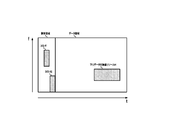
- the configuration of the downlink signal illustrated in FIG. 2 schematically shows a subframe which is one component of a radio frame, and in a space defined using time on the horizontal axis and frequency on the vertical axis, It has a control area and a data area.
- the downlink signal (also referred to as downlink subframe) has a plurality of radio resources defined at least on the frequency axis and the time axis. Each of the plurality of radio resources is configured to be distinguishable by a resource number assigned to each of a predetermined number of radio resources.
- the resource number may be a single value or may be defined by a value on the frequency axis and a value on the time axis.
- the resource number in the present disclosure may be a value useful for specifying the location of the radio resource, and is not limited to any one concept.
- the term “resource number” may also be described in the case of indicating the position of the radio resource in which the downlink data signal is arranged, and the term “resource number” also in the case of indicating the position of the radio resource May be explained in terms of
- the “resource number” in the case of indicating the position of the radio resource in which the downlink data signal is arranged and the “resource number” in the case of indicating the position of the radio resource in which the downlink control information is arranged are necessarily It should be noted that the concepts are not necessarily at the same level.
- radio resources in the control area in which downlink control information is allocated are specified in units of CCE (Control Channel Element)
- radio resources in a data area in which downlink data signals are allocated are specified in a unit different from CCE. It may be done.
- resource number may be used in any case for simplification of the description, it should be appropriately read and understood based on the above-described meaning.
- the CCE number also referred to as a CCE index number
- the CCE number for specifying the above-mentioned CCE-based radio resource is an example of a resource number assigned to the radio resource in the control area.
- the control region illustrated in FIG. 2 is formed by a set of radio resources located forward in the time axis, and may be referred to, for example, as PDCCH (Physical Downlink Control CHannel).
- the data area illustrated in FIG. 2 is formed by a set of radio resources located behind the control area on the time axis, and may be referred to as, for example, PDSCH (Physical Downlink Shared CHannel).
- downlink control information can be stored for each wireless terminal.
- DCI downlink control information
- Downlink control information DCI # 2 addressed to the second radio terminal 10B to which # 1 is assigned is stored in the control area.
- the radio resource information may include, for example, information indicating the position of the allocated downlink data radio resource, information indicating a modulation scheme, and the like.
- the radio terminal performs demodulation / decoding processing (processing such as demodulation, reception, etc.) of the downlink data signal addressed to the own terminal multiplexed to the corresponding downlink data radio resource based on the radio resource information in the downlink control information directed to the own terminal Processing (also referred to as processing).
- the suppression process of the interference component in the wireless communication system 1 may be, for example, a successive interference cancellation (SIC) scheme.
- a wireless base station transmits a signal multiplexed on the transmission power axis to two or more wireless terminals having different signal to noise ratios (SN ratios), and a wireless terminal having a large SN ratio Is a technique in which a desired signal is taken out by performing interference cancellation one after another.
- SN ratios signal to noise ratios
- obtaining information on the downlink data signal addressed to the other terminal multiplexed to the same downlink data radio resource eliminates the interference component from the downlink signal from the radio base station 20 and It is useful in shortening the time required to acquire the downlink data signal addressed to the terminal.
- obtaining information on downlink data signals addressed to other terminals multiplexed in the same downlink data radio resource is extremely reliable and low delay in the fifth generation mobile communication system. It is important to realize communication.
- the error detection code D12 is scrambled by the identification information on the first wireless terminal 10A, and may be descrambled based on the identification information on the first wireless terminal 10A.
- the reference information D10 and the radio resource information D11 may not be the target of scrambling based on the identification information on the first radio terminal 10A.
- the identification information related to the first radio terminal 10A may also be referred to as Radio Network Temporary Identifier (RNTI) or C-RNTI (Cell RNTI).
- RNTI Radio Network Temporary Identifier
- Cell RNTI Cell RNTI
- the radio resource information D21 may not be the target of scrambling based on the identification information on the second radio terminal 10B.
- the identification information on the second radio terminal 10B may also be referred to as Radio Network Temporary Identifier (RNTI) or C-RNTI (Cell RNTI).
- the reference information D10 indicates the position of the radio resource to which the downlink control information for another terminal is mapped among the radio resources in the control area.
- reference information D10 stored in downlink control information DCI # 1 addressed to the first wireless terminal is in the control area to which downlink control information DCI # 2 addressed to the second wireless terminal is mapped.
- the first wireless terminal 10A acquires the downlink control information DCI # 2 addressed to the second wireless terminal based on the reference information stored in the downlink control information DCI # 1 addressed to the first wireless terminal. It is possible to execute reception processing for the downlink data signal addressed to the second wireless terminal based on the radio resource information D21 stored in the acquired downlink control information DCI # 2.
- FIG. 4 is a diagram showing an example of the content of reference information.
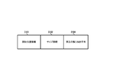
- the reference information D10 includes start position information D101 indicating the position of the top of the radio resource to which downlink control information of other terminals is mapped, and size information D102 indicating the length of the radio resource. .
- FIG. 5 schematically shows the arrangement of radio resources and downlink control information in the control area.
- the downlink control information DCI # 1 addressed to the first wireless terminal is arranged (mapped) in a set of a CCE with index number 16 and a CCE with number 17.
- the downlink control information DCI # 2 addressed to the second wireless terminal is arranged in a set of CCE with index number 22 and CCE with number 23.
- the reference information D10 stored in the downlink control information DCI # 1 addressed to the first wireless terminal indicates the position of the CCE where the downlink control information DCI # 2 addressed to the second wireless terminal is arranged.
- the reference information D10 is, for example, the index number (22 in the example of FIG. 5) of the CCE at the head (left side in FIG. 5) in the set of CCEs in which the downlink control information DCI # 2 addressed to the second radio terminal is arranged As start position information D101.
- the CCE in the control area has a total of 33 index numbers from 0 to 32 and all index numbers can be represented by 6 bits, so the data length of the start position information D101 Should have 6 bits.
- the reference information D10 has, for example, the length (2 in the example of FIG. 5) of the set of CCEs in which the downlink control information DCI # 2 addressed to the second wireless terminal is arranged, as size information.
- the size information D102 may be referred to as an aggregation level.
- the aggregation level may be configured to have, for example, four stages of level 1, level 2, level 4 and level 8.
- the aggregation level is level 1 in length.
- the set of CCEs to which downlink control information is mapped is 2 in length.
- the set of CCEs to which downlink control information is mapped is 2 in length.
- the set of CCEs to which downlink control information is mapped is 4 in length.
- the set of CCEs to which downlink control information is mapped is of length 8.
- the data length of the size information D 102 may be 2 bits.
- the first radio terminal 10A when the first radio terminal 10A succeeds in detecting the downlink control information DCI # 1 addressed to the first radio terminal, for example, by blind search of the radio resources in the control area, the downlink control information DCI Based on the reference information D10 in # 1, downlink control information DCI # 2 directed to the second wireless terminal can be obtained.
- the first radio terminal 10A can omit the blind search of the downlink control information DCI # 2 addressed to the second radio terminal by using the reference information D10. Therefore, the first wireless terminal 10A can shorten the time required to acquire the downlink control information DCI # 2 addressed to the second wireless terminal, as compared with the time required for the blind search.
- the reference information is, for example, a total of 8 bits of start position information D101 of 6 bit length and size information D102 of 2 bit length
- the information for acquiring the downlink data signal addressed to the second wireless terminal includes downlink control information addressed to the second wireless terminal and downlink control addressed to the first wireless terminal
- information is redundantly transmitted and received, according to the first embodiment, such duplication can be avoided.
- Such an aspect is for ultra-high reliability and low delay communication while improving transmission efficiency of information necessary for interference cancellation in a non-orthogonal multiple access system under consideration of application to the fifth generation mobile communication system and the like. Useful for meeting functional requirements.
- FIG. 6 is a diagram illustrating an example of the flow of processing in the wireless terminal 10 according to the first embodiment.
- downlink control information addressed to the own terminal is searched by searching for downlink control information addressed to the own terminal (also referred to as blind search) in the control region of the subframe illustrated in FIG.
- the execution may be started when the information detection is successful.
- the error detection code attached to the downlink control information is descrambled with the identification information on the own terminal, and the error detection code after descrambling detects the error for the downlink control information Is done.
- the radio terminal 10 determines that the detection of downlink control information addressed to the own terminal has succeeded.
- the radio terminal 10 may determine that the downlink control information is downlink control information directed to another terminal.
- the radio terminal 10 acquires, from the downlink signal transmitted by the radio base station 20, first downlink control information that is downlink control information directed to the own terminal (S101). According to the example illustrated in FIG. 2, in processing S101, the radio terminal 10 acquires the first downlink control information DCI # 1 arranged in the control area. Then, the radio terminal 10 determines whether reference information is present in the first downlink control information (S102).
- the wireless terminal 10 may determine, for example, based on the data length of the first downlink control information acquired in processing S101, whether reference information is present.
- the wireless terminal 10 determines whether the reference information exists by determining whether the data length of the first downlink control information corresponds to the data length of the downlink control information including the reference information. You may judge.
- the first downlink control information may include format information indicating whether it is downlink control information including reference information. That is, in processing S102, the radio terminal 10 may determine whether reference information exists based on the format information of the first downlink control information.
- step S102 when it is determined that the reference information exists in the first downlink control information (YES in S102), the radio terminal 10 determines from the downlink signal transmitted from the radio base station 20 from the first downlink control information. Based on the acquired reference information, second downlink control information that is downlink control information addressed to another terminal is acquired (S103). According to the example shown in FIG. 2, the radio terminal 10 acquires the downlink control information DCI # 2 addressed to the other terminal based on the reference information acquired from the first downlink control information DCI # 1.
- the radio terminal 10 may ignore the error detection code in the second downlink control information. This is because, as described above, the error detection code in the second downlink control information is scrambled based on the identification information on another terminal that is the original destination of the second downlink control information, This is because the content is meaningless unless descrambling is performed using the identification information.
- wireless terminal 10 when ignoring the error detection code
- the first downlink control information includes the reference information means that the radio base station 20 instructs the radio terminal 10 to execute the interference removal process in the non-orthogonal multiple access system. Means In other words, the radio base station 20 transmits the first downlink control information including the reference information to the radio terminal 10 having a high SN ratio. This is because, in the orthogonal multiple access scheme, the radio base station 20 allocates small transmission power to the radio terminal 10 having a high SN ratio, and allocates large transmission power to the radio terminal 10 having a low SN ratio.
- the radio communication system 1 it is not necessary to notify the wireless terminal of identification information for descrambling the CRC of the downlink control information addressed to the other terminal.
- identification information such as RNTI or C-RNTI of another terminal is required for descrambling the CRC of downlink control information addressed to the other terminal
- the radio communication system according to the first embodiment stores the identification information. For example, an area of 16 bits in length, which is an area of
- the radio terminal 10 acquires radio resource information stored in the second downlink control information, and based on the radio resource information acquired from the second downlink control information, a second downlink that is a downlink data signal addressed to another terminal A data signal is received (S104). According to the example shown in FIG. 2, in the processing S104, the radio terminal 10 is multiplexed with the downlink data radio resource # 1 based on the radio resource information acquired from the second downlink control information DCI # 2. Receive the downlink data signal addressed to the terminal.
- FIG. 7 is a diagram showing an example of contents of second downlink control information.
- the second downlink control information illustrated in FIG. 7 includes a first information element (Resource allocation header) D201 of 1 bit and a second information element (Resource block assignment for bit length) determined according to the system band of the downlink signal.
- RA Type 0 D202, 2-bit third information element (TPC for PUCCH) D203, 2-bit fourth information element (Downlink Assignment Index) D 204, two-way wireless communication method between wireless terminal and wireless base station
- TDD Time Division Duplex
- the information elements corresponding to the radio resource information D21 of the second downlink control information DCI # 2 shown in FIG. 3 are the sixth information element D206 to the thirteenth information element
- the radio terminal 10 downlink data addressed to the other terminal multiplexed in the downlink data radio resource # 1.
- a signal may be received.
- the present disclosure is not limited to the contents of the second downlink control information illustrated in FIG. 7.
- technical common sense shown in the above-mentioned Non-Patent Documents 1 to 19 is incorporated.
- the radio terminal 10 executes a process of removing an interference component from the downlink signal of the downlink data radio resource # 1 based on the second downlink data signal acquired in the process S104 (S105).
- the radio terminal 10 performs a first downlink data signal that is a downlink data signal for the own terminal, based on the radio resource information of the first downlink control information, for the downlink signal after removing the interference component in processing S105. It receives (S106). Thereby, the radio terminal 10 receives the downlink data signal addressed to the own terminal while suppressing the influence of the interference component by the downlink data signal addressed to the other terminal multiplexed to the same radio resource by the non-orthogonal multiple access scheme. Can.
- the radio terminal 10 when it is determined in the processing S102 that the reference information does not exist in the first downlink control information (NO in S102), the radio terminal 10 omits the execution of the processing S103 to the processing S105 described above.
- the reason is that the reference information does not exist in the first downlink control information means that the radio base station 20 does not instruct the radio terminal 10 to execute the interference cancellation process in the non-orthogonal multiple access system.
- FIG. 8 is a diagram illustrating an example of the flow of processing in the wireless base station 20 according to the first embodiment.
- the flow of the process illustrated in FIG. 8 may start to be performed, for example, when generating a downlink signal as illustrated in FIG. 2.
- the “value corresponding to the SN ratio” in the present disclosure may be referred to as, for example, a CQI (Channel Quality Indicator) or a CSI (Channel Status Information), or a coding rate (Coding Rate). , Or may be referred to as a modulation coding scheme (MCS), may be referred to as an MCS index, or may be referred to as a transport block size (TBS).
- MCS modulation coding scheme
- TBS transport block size
- the radio base station 20 selects a radio resource (also referred to as a second radio resource) of the control area to be allocated to the second downlink control information which is downlink control information for the second radio terminal (S202) ).
- the radio base station 20 determines the number of connections (also referred to as an aggregation level), which is the number of radio resources to be allocated to downlink control information, based on the value indicated in the measurement result report of the second radio terminal. It determines and selects the radio resource according to the number of connection. In the example illustrated in FIG. 5, a set of the radio resource CCE [22] and the radio resource CCE [23] is selected for the second downlink control information DCI # 2 directed to the second radio terminal. That is, the number of connections in this example is two.
- the radio base station 20 generates reference information indicating the position of the second radio resource (S203).
- the radio base station 20 refers to the start position information having the index number of the first radio resource in the set of radio resources selected in process S202, and the size information having the number of connections determined in process S202. You may store in.
- the radio base station 20 stores the reference information generated in the processing S203 in first downlink control information which is downlink control information addressed to the first wireless terminal (S204). As a result, first downlink control information DCI # 1 having reference information as illustrated in FIG. 3 is generated.
- the radio base station 20 sets the first downlink control information DCI # 1 addressed to the first wireless terminal and the second downlink control information DCI # 2 addressed to the second wireless terminal in the control area of the downlink signal. It arranges (S205). At that time, the error detection code D12 of the first downlink control information DCI # 1 is arranged in a scrambled format with the identification information on the first wireless terminal corresponding to the first downlink control information DCI # 1. The error detection code D22 of the second downlink control information DCI # 2 is arranged in a scrambled form with the identification information on the second wireless terminal corresponding to the second downlink control information DCI # 2.
- the first downlink data signal and the downlink data radio resource # 1 to which the first downlink data signal and the second downlink data signal are multiplexed are used.
- the related first downlink control information DCI # 1 and the second downlink control information DCI # 2 related to the second downlink data signal are illustrated, and the others are omitted.
- the wireless terminal 20 transmits the generated downlink signal to the area 30 of the wireless service as illustrated in FIG. 1 (S207).
- the above is an example of the flow of processing in the radio base station 20 according to the first embodiment.
- FIG. 9 is a diagram illustrating an example of contents of reference information according to a second embodiment.
- the reference information illustrated in FIG. 9 further includes a second error detection code D103 in addition to the content example of the reference information according to the first embodiment.
- the second error detection code D103 is an error detection code of downlink control information addressed to the other terminal, and is an error detection code before being scrambled based on the identification information of the other terminal.
- the flow of the process in the wireless base station 20 according to the second embodiment is the same as the flow of the process in the wireless base station 20 according to the first embodiment illustrated in FIG. 8 and therefore, the example illustrated in FIG. . That is, in the process S203 shown in FIG. 8, the radio base station 20 according to the second embodiment not only generates reference information indicating the position of the second radio resource, but also performs downlink control for the second radio terminal.
- a second error detection code which is an error detection code used for error detection of information, is stored in the reference information. According to the example shown in FIG.
- the error detection code generated for the set of parameters necessary for estimation of the interference component is stored in the reference information as the third error code D104.
- the code length of the error detection code can be further compressed than the second error detection code D103 which is the error detection code for the entire downlink control information.
- the flow of processing in the radio terminal 10 and the radio base station 20 according to the third embodiment is the same as that of the second embodiment.
- the radio base station 20 according to the third embodiment may perform processing in accordance with the above-described purpose. For example, when the radio base station 20 according to the third embodiment generates the first downlink control information addressed to the first radio terminal 10A, all of the second downlink control information addressed to the second radio terminal 10B is generated.
- the third error detection code D104 may be generated based on a set of parameters necessary for estimation of the interference component.
- An example of a set of parameters necessary for estimation of interference components is, for example, eight information elements from the sixth information element D206 to the thirteenth information element D213 illustrated in FIG.
- the process may be performed in accordance with the above-described purpose.
- the first wireless terminal 10A according to the third embodiment performs error detection based on the third error detection code D104
- the first wireless terminal 10A makes an error with respect to all of the second downlink control information acquired based on the reference information.
- error detection may be performed on a set of parameters required to estimate an interference component.
- the third error detection code D104 can compress the code length of the error detection code more than the second error detection code D103 which is the error detection code for the entire downlink control information. . Such an action is further useful for realizing ultra-reliable low-latency communication while improving the transmission efficiency of information on interference components.
- the first sub information element D231 corresponds to the size information D102 illustrated in FIG.
- the second sub information element D232 corresponds to the start position information D101 illustrated in FIG.
- the first information element D220 indicates the number of second information elements D230, D240, D250 stored in the reference information.
- the example of FIG. 11 illustrates three second information elements D230, D240, and D250 being stored, the first modification is not limited thereto.
- the reference information according to the first modification may have one second information element.
- the reference information D10 illustrated in each of the embodiments and the modifications described above includes start position information D101 and size information D102.
- the reference information D10 in the present application is not limited to this.
- the reference information D10 may include the start position information D101 but not include the size information D102.
- the size information D102 may be omitted. Thereby, the reference information can be further compressed. Such an action is further useful for realizing ultra-reliable low-latency communication while improving the transmission efficiency of information on interference components.
- FIG. 12 is a diagram showing an example of a hardware configuration of the wireless terminal 10 and the wireless base station 20 in the wireless communication system 1.
- the wireless terminal 10 illustrated in FIG. 12 includes a wireless communication circuit 101, a processing circuit 102, and a memory 103. In the radio terminal 10 shown in FIG. 12, the illustration of the antenna is omitted.
- the wireless terminal 10 may also include a display device such as a liquid crystal display, an input device such as a touch panel, and a battery such as a lithium-ion rechargeable battery.
- the wireless communication circuit 101 receives a baseband signal from the processing circuit 102 in the downlink (also referred to as downlink), generates a wireless signal of a predetermined output level from the baseband signal, and wirelessly transmits the signal via an antenna. It is configured to radiate a signal into space.
- the wireless communication circuit 101 receives a wireless signal input from an antenna, converts the wireless signal into a baseband signal, and supplies the baseband signal to the processing circuit 102.
- Configured to The wireless communication circuit 101 can be communicably connected to the processing circuit 102 through a transmission circuit.
- the transmission circuit for example, a transmission circuit conforming to a standard such as M-PHY or Dig-RF can be mentioned.
- the wireless communication circuit 101 has an aspect as a communication unit (also referred to as a transmission / reception unit or a first transmission / reception unit) having a function of performing wireless communication with the wireless base station 20.
- the processing circuit 102 is a circuit configured to perform baseband signal processing.
- the processing circuit 102 is configured to generate a baseband signal in the uplink based on the protocol stack in the wireless communication system and to output the baseband signal to the wireless communication circuit 101.
- the processing circuit 102 is configured to perform reception processing such as demodulation and decoding on the downlink based on a protocol stack in the wireless communication system with respect to a baseband signal input from the wireless communication circuit 101.
- the processing circuit 102 transmits from the upper layer to the lower layer toward the radio base station 20 as a receiving device according to the procedure of the protocol stack in which the function of wireless communication is divided into a plurality of layers.
- the processing circuit 102 sequentially processes radio signals received via the radio communication circuit 101 from the lower layer to the upper layer in accordance with the protocol stack procedure in which the function of radio communication is divided into a plurality of layers.
- receiving an input of a baseband signal from the wireless communication circuit 101 has an aspect of receiving a wireless signal from the wireless base station 20 via the wireless communication circuit 101.
- the processing circuit 102 may be, for example, an arithmetic device that realizes the operation of the wireless terminal 10 according to the various embodiments described above by reading and executing a program stored in the memory 103.
- the processing circuit 102 has an aspect as an execution subject of the flow of processing in the wireless terminal 10 illustrated in FIG.
- Examples of the processing circuit 102 include a central processing unit (CPU), a micro processing unit (MPU), a digital signal processor (DSP), and a field programmable gate array (FPGA).
- the processing circuit 102 may be a multi-core processor including two or more cores. Also, the processing circuit 102 may implement two or more processing circuits 102 according to each layer in the protocol stack of the wireless communication system.
- the processing circuit 102 that executes processing as a MAC entity belonging to the MAC (Medium Access Control) layer, the processing circuit 102 that executes processing as an RLC entity that belongs to the RLC (Radio Link Control) layer, and PDCP (Packet Data)
- the processing circuit 102 that executes processing as a PDCP entity belonging to the Convergence Protocol) layer may be implemented separately.
- the processing circuit 102 is also referred to as a C-CPU.
- the wireless terminal 10 may implement, in addition to the processing circuit 102, a processor circuit also referred to as an A-CPU that executes an application.
- the processing circuit 102 may be mounted on one chip together with a processor circuit also referred to as an A-CPU, or may be mounted as an individual chip.
- the processing circuit 102 has an aspect as a control unit (also referred to as a first control unit) having a function of controlling the operation of the wireless terminal 10.
- the memory 103 is a circuit configured to store and hold data and programs related to baseband signal processing executed by the processing circuit 102.
- the memory 103 is configured to include at least one or both of a non-volatile storage device and a volatile storage device.
- a non-volatile storage device For example, RAM (Random Access Memory), ROM (Read Only Memory), SSD (Solid State Drive), HDD (Hard Disk Drive), etc. may be mentioned.
- a memory 103 is a generic term for various storage devices such as a main storage device and an auxiliary storage device.
- two or more memories 103 may be mounted in the memory 103 in accordance with each layer in the protocol stack of the wireless communication system.
- a memory 103 used for processing as a MAC entity belonging to the MAC layer a memory 103 used for processing as an RLC entity belonging to the RLC layer, and a memory 103 used for processing as a PDCP entity belonging to the PDCP layer , May be implemented separately.
- the wireless base station 20 illustrated in FIG. 12 includes a wireless communication circuit 201, a processing circuit 202, a memory 203, and a wired communication circuit 204.
- the illustration of the antenna is omitted.
- the combination of the wireless communication circuit 201 and the processing circuit 202 is not limited to one-to-one, and one wireless communication circuit 201 may be associated with a plurality of processing circuits 202 or a plurality of wireless communication circuits 201 may be combined. It is also possible to associate one processing circuit 202 or associate a plurality of wireless communication circuits 201 with a plurality of processing circuits 202.
- the wireless communication circuit 201 has an aspect as a communication unit (also referred to as a transmission / reception unit or a second transmission / reception unit) having a function of performing wireless communication with the wireless terminal 10.
- the processing circuit 202 is a circuit configured to perform baseband signal processing.
- the processing circuit 202 is configured to generate a baseband signal in the downlink based on the protocol stack in the wireless communication system and to output the baseband signal to the wireless communication circuit 201.
- the processing circuit 202 is configured to perform reception processing such as demodulation and decoding on the uplink based on the protocol stack in the wireless communication system, on the baseband signal input from the wireless communication circuit 201.
- the processing circuit 202 transmits the transmission data for the radio terminal 10 as the receiving device from the upper layer to the lower layer in accordance with the protocol stack procedure in which the function of wireless communication is divided into a plurality of layers.
- the processing circuit 202 sequentially processes radio signals received via the wireless communication circuit 201 from the lower layer to the upper layer in accordance with the protocol stack procedure in which the function of wireless communication is divided into a plurality of layers.
- receiving an input of a baseband signal from the wireless communication circuit 201 in the uplink has an aspect of receiving a wireless signal from the wireless terminal 10 via the wireless communication circuit 201.
- the processing circuit 202 may be, for example, an arithmetic unit that implements the operation of the radio base station 20 according to the various embodiments described above by reading and executing a program stored in the memory 203. In other words, the processing circuit 202 has an aspect as an execution subject of the processing flow in the radio base station 20 illustrated in FIG. 8. Examples of the processing circuit 202 include a central processing unit (CPU), a micro processing unit (MPU), a digital signal processor (DSP), and a field programmable gate array (FPGA).
- the processing circuit 202 may be a multi-core processor including two or more cores. Also, the processing circuitry 202 may implement more than one processing circuitry 202 depending on each layer in the protocol stack of the wireless communication system.
- the processing circuit 202 that performs processing as a MAC entity that belongs to the MAC layer, the processing circuit 202 that performs processing as an RLC entity that belongs to the RLC layer, and the processing circuit that performs processing as a PDCP entity that belongs to the PDCP layer 202 may be implemented separately.
- the processing circuit 202 has an aspect as a control unit (also referred to as a second control unit) having a function of controlling the operation of the radio base station 20.
- the memory 203 is a circuit configured to store and hold data and programs related to baseband signal processing executed by the processing circuit 202.
- the memory 203 is configured to include at least one or both of a non-volatile storage device and a volatile storage device.
- a non-volatile storage device For example, RAM (Random Access Memory), ROM (Read Only Memory), SSD (Solid State Drive), HDD (Hard Disk Drive), etc. may be mentioned.
- a memory 203 is a generic term for various storage devices such as a main storage device and an auxiliary storage device. Note that, as with the processing circuit 202, two or more memories 203 may be mounted in the memory 203 in accordance with each layer in the protocol stack of the wireless communication system.
- a memory 203 used for processing as a MAC entity belonging to the MAC layer a memory 203 used for processing as an RLC entity belonging to the RLC layer, and a memory 203 used for processing as a PDCP entity belonging to the PDCP layer , May be implemented separately.
- the wired communication circuit 204 converts it into packet data of a format that can be output to another device and transmits it to the other device, or extracts data etc. from packet data received from the other device, and the memory 203 or processing circuit Output to 202 or the like.
- Examples of other devices may include other wireless base stations, MME (Mobility Management Entity), SGW (Serving Gateway), and the like.
- MME and SGW are also referred to as core nodes, and the logical communication interface used to communicate with the core nodes is also referred to as an S1 interface.
- the logical communication interface used to communicate with other wireless base station devices is also referred to as an X2 interface.
- the configuration of the embodiment of the present disclosure shows an example for embodying the technical idea of the present invention, and is not intended to limit the present invention to the configuration of this embodiment.
- the present invention is equally applicable to the other embodiments included in the claims.
- the terms in the present disclosure may be renamed in the future specification of the fifth generation mobile communication system.
Landscapes
- Engineering & Computer Science (AREA)
- Computer Networks & Wireless Communication (AREA)
- Signal Processing (AREA)
- Mobile Radio Communication Systems (AREA)
Abstract
無線基地局は、複数の無線端末のうち、非直交多元接続方式により同じ下り無線リソースに下りデータ信号を多重する第一の無線端末と第二の無線端末とを選択し、第一の無線端末宛ての第一の下りデータ信号に関する下り制御情報である第一の下り制御情報に、第二の無線端末宛ての第二の下りデータ信号に関する下り制御情報である第二の下り制御情報が配置される無線リソースの位置を示す参照情報を格納し、第一の下り制御情報と第二の下り制御情報と第一の下りデータ信号と第二の下りデータ信号とが配置された下りリンク信号を、無線通信回路を用いて送信する。
Description
本発明は、非直交多元接続方式が可能な無線通信システム、無線基地局、無線端末に関する。
近年、携帯電話システム(セルラーシステム)等の無線通信システム(移動通信システムとも称される)において、無線通信の更なる高速化・大容量化等を図るため、次世代の無線通信技術について議論が行われている。例えば、標準化団体である3GPP(3rd Generation Partnership Project)では、LTE(Long Term Evolution)と呼ばれる通信規格や、LTEの無線通信技術をベースとしたLTE-A(LTE-Advanced)と呼ばれる通信規格の仕様策定を既に行い、その機能の拡張のための検討作業が継続的に行なわれている。例えば、ITU-R(International Telecommunication Union Radio communications sector)から提示された運用シナリオや技術要件の内容を実現する第五世代移動通信システム(5Gシステムとも称される)の標準化に関する議論が行われている。
第五世代移動通信システムでは、周波数利用効率(帯域利用効率とも称される)を向上させるために、多元接続方式として非直交多元接続方式(NOMA: Non Orthogonal Multiple Access)を採用することが検討されている。非直交多元接続方式では、異なる無線端末に対し、時間及び周波数において同一の無線リソースが割当てられる。その際、無線基地局は、伝搬損失(伝送損失、パスロスとも称される)が大きい無線端末に対して送信電力を多く割当て、伝搬損失が小さい無線端末に対して送信電力を少なく割当てる。これにより、電力軸上での無線リソースの多重が行われ、さらなる周波数利用効率の向上が図られている。別言すると、同一時間及び同一周波数の無線リソース上に、複数のユーザの各々に搬送する信号が多重して送信される。
下りリンク信号に対して、電力軸で複数のユーザの各々に搬送する信号を多重する場合、無線端末は、他端末宛ての信号(下りデータ信号、データ信号とも称される)を復調し、復調した他端末宛ての下りデータ信号に基づいて下りリンク信号から干渉成分を除去し(干渉除去、干渉相殺、干渉抑制、干渉キャンセルとも称される)、その後、自端末宛ての下りデータ信号を復調する。そのため、非直交多元接続方式の無線端末は、他端末宛ての下りデータ信号を復調するための情報(干渉成分に関する情報とも称される)を、何らかの方法を用いて取得することが望まれる。別言すると、非直交多元接続方式の無線基地局は、無線端末に対して、干渉成分に関する情報を、何らかの方法を用いて通知することが望まれる。
従来技術では、無線基地局が、第一の無線端末に対して下りリンク制御情報(DCI: Downlink Control Information)を送信する際に、第二の無線端末宛ての下りデータ信号を復調するための情報を、第二の無線端末宛ての下り制御情報と第一の無線端末宛ての下りリンク制御情報とで重複して送信することが提案されている(例えば、特許文献1、特許文献2)。
3GPP TS 36.211 V14.2.0 (2017-03)
3GPP TS 36.212 V14.2.0 (2017-03)
3GPP TS 36.213 V14.2.0 (2017-03)
3GPP TS 36.300 V14.2.0 (2017-03)
3GPP TS 36.321 V14.2.0 (2017-03)
3GPP TS 36.322 V14.0.0 (2017-03)
3GPP TS 36.323 V14.2.0 (2017-03)
3GPP TS 36.331 V14.2.0 (2017-03)
3GPP TS 36.413 V14.2.0 (2017-03)
3GPP TS 36.423 V14.2.0 (2017-03)
3GPP TS 36.425 V14.0.0 (2017-03)
3GPP TR 38.801 V14.0.0 (2017-03)
3GPP TR 38.802 V14.0.0 (2017-03)
3GPP TR 38.803 V14.0.0 (2017-03)
3GPP TR 38.804 V14.0.0 (2017-03)
3GPP TR 38.900 V14.2.0 (2016-12)
3GPP TR 38.912 V14.0.0 (2017-03)
3GPP TR 38.913 V14.0.0 (2017-03)
Y. Saito, Y. Kishiyama, A. Benjebbour, T. Nakamura, A. Li, and K. Higuchi, "Non-orthogonal multiple access (NOMA) for future radio access," Proc. IEEE VTC2013-Spring, pp.1-5, Dresden, Germany, June 2013.
第五世代移動通信システムでは、例えば、触覚通信や拡張現実など、従来と異なるレベルの低遅延が要求されるサービスの登場が期待されており、超高信頼・低遅延通信(URLLC:Ultra-Reliable and Low-Latency Communications)を機能要件の一つとしている。そのため、例えば、第四世代移動通信システムであるLTEでは、無線区間におけるパケットの送信元から送信先への遅延として10[ミリ秒]の遅延が想定されるのに対し、第五世代移動通信システムでは、1[ミリ秒]以下の遅延を実現することが目指されている。
従来技術では、無線基地局は、時間及び周波数において同じ無線リソースに下りデータ信号が多重された各々の無線端末に対して、他端末宛ての下りデータ信号を復調するための情報を、各無線端末宛ての下り制御情報を介して通知する。これにより、自端末宛ての下り制御情報をブラインドサーチすることで、自端末宛ての下りデータ信号を復調するための情報だけでなく、他端末宛ての下りデータ信号を復調するための情報も取得することができる。しかし、下りデータ信号を復調するための情報が重複して送信されることとなり、無線リソースの利用効率が減少する、という問題がある。
開示の技術は、第五世代移動通信システムなどへの適用を検討されている非直交多元接続方式における、干渉成分に関する情報の伝送効率を向上させつつ、超高信頼・低遅延通信の機能要件を満たすことが可能な無線通信システム、無線基地局、無線端末を提供することを目的とする。
本開示の一側面によれば、非直交多元接続方式による無線サービスを提供可能な無線通信システムは、無線基地局と、複数の無線端末とを備える。
本開示の一側面によれば、無線通信システムにおける無線基地局は、前記複数の無線端末のうち、非直交多元接続方式により同じ下り無線リソースに下りデータ信号を多重する第一の無線端末と第二の無線端末とを選択する処理と、前記第一の無線端末宛ての第一の下りデータ信号に関する下り制御情報である第一の下り制御情報に、前記第二の無線端末宛ての第二の下りデータ信号に関する下り制御情報である第二の下り制御情報が配置される無線リソースの位置を示す参照情報を格納する処理と、前記第一の下り制御情報と、前記第二の下り制御情報と、前記第一の下りデータ信号と、前記第二の下りデータ信号とが配置された下りリンク信号を、無線通信回路を用いて送信する処理と、
を実行する処理回路を備える。
を実行する処理回路を備える。
本開示の一側面によれば、無線通信システムにおける第一の無線端末は、前記無線基地局により送信された前記下りリンク信号から、前記第一の無線端末宛ての第一の下り制御情報を取得する処理と、前記第一の下り制御情報から取得した前記参照情報に基づいて、前記第二の無線端末宛ての前記第二の下り制御情報を取得する処理と、前記第二の下り制御情報に基づいて、前記第二の無線端末宛ての前記第二の下りデータ信号を受信する処理と、前記第二の下りデータ信号による干渉成分を、前記下りリンク信号から除去する処理と、前記干渉成分の除去後の前記下りリンク信号から、前記第一の下り制御情報に基づいて、前記第一の無線端末宛ての前記第一の下りデータ信号を受信する処理と、を実行する処理回路を備える。
開示の技術の一側面によれば、第五世代移動通信システムなどへの適用を検討されている非直交多元接続方式における、干渉成分に関する情報の伝送効率を向上させつつ、超高信頼・低遅延通信の機能要件を満たすことが可能となる。
以下に、本願が開示する無線通信システム、無線基地局、無線端末の実施例について、図面を参照しながら詳細に説明する。なお、以下に示す実施例は開示の技術を限定するものではない。また、以下に示す各実施例は、適宜組み合わせて実施してもよいことはいうまでもない。ここで、非特許文献1ないし非特許文献19の全ての内容は、参照することによりここに援用される。
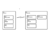
<実施例1> 図1は、実施例1に係る無線通信システム1の概略的構成を示す図である。図1に例示される無線通信システム1は、第一の無線端末10A(無線端末10A、UE#1とも称される)と、第二の無線端末10B(無線端末10B、UE#2とも称される)と、無線基地局20とを有する。第一の無線端末10Aと第二の無線端末10Bとは、無線基地局20が提供する無線サービスのエリア30(セル、マクロセル、スモールセル、ピコセル、セクタ、ゾーンなどとも称される)内に存在しており、無線基地局20から送信される下りリンク信号を受信することができるように構成される。本実施例1に係る無線基地局20は、第一の無線端末10A及び第二の無線端末10Bと、非直交多元接続方式により無線通信を行うように構成され得る。図1に示す例では、説明の簡略化のため、第一の無線端末10Aと第二の無線端末10Bとを図示しているが、3台以上の無線端末が存在しても良い。なお、第一の無線端末10A及び第二の無線端末10Bを総称する概念として、無線端末10と称する場合がある。第一の無線端末10Aにとって、自端末は第一の無線端末10Aであり、他端末は第二の無線端末10Bを含む他の無線端末を意味する。第二の無線端末10Bにとって、自端末は第二の無線端末10Bであり、他端末は第一の無線端末10Aを含む他の無線端末を意味する。
非直交多元接続方式の無線基地局20は、周波数と時間とで定義される複数の無線リソースのうち時間及び周波数において同じ無線リソースを、第一の無線端末10Aと、第二の無線端末10Bとに割当てた場合、無線基地局20の近傍に位置する第一の無線端末10Aに対して小送信電力を割当て、無線基地局20から遠方に位置する第二の無線端末10Bに対して大送信電力を割当てる。別言すると、第一の無線端末10Aは、無線基地局20の近傍に位置するため、無線基地局20からの下りリンク信号の伝搬損失は比較的小さくて済む。一方、第二の無線端末10Bは、無線基地局20から遠方に位置するため、無線基地局20からの下りリンク信号の伝搬損失は比較的大きくなる。そのため、無線基地局20は、第二の無線端末10Bに対する送信電力を、第一の無線端末10Aに対する送信電力よりも多く割当てることで、伝搬損失による減衰を補うことが期待される。
非直交多元接続方式において、第二の無線端末10Bは、無線基地局20からの下りリンク信号を受信する場合、第二の無線端末10B宛ての下りデータ信号(第二のデータ信号とも称される)と、第一の無線端末10A宛ての下りデータ信号(第一のデータ信号とも称される)とが多重された無線リソースから、自端末宛てである第二の無線端末10B宛ての下りデータ信号を取得する。その際、無線基地局20から第二の無線端末10Bまでの伝搬損失により、無線基地局20からの下りリンク信号のうち、第一の無線端末10A宛ての下りデータ信号は無視し得る程度に低下する。そのため、第二の無線端末10Bは、自端末宛てである第二の無線端末10B宛ての下りデータ信号を取得する際に、第一の無線端末10A宛ての下りデータ信号による影響を考慮しなくても良い。別言すると、第二の無線端末10Bにとって、第一の無線端末10A宛ての下りデータ信号による干渉成分は無視し得る。
一方、第一の無線端末10Aは、無線基地局20からの下りリンク信号を受信する場合、時間及び周波数において同じ無線リソースに多重されている第二の無線端末10B宛ての下りデータ信号の送信電力が大きいため、第二の無線端末10B宛ての下りデータ信号による干渉成分を除去することが望まれる。別言すると、第一の無線端末10Aは、自端末宛てである第一の無線端末10A宛ての下りデータ信号を取得する際に、第二の無線端末10B宛ての下りデータ信号を復調などして取得し、取得した第二の無線端末10B宛ての下りデータ信号に基づく干渉成分を除去することが望まれる。別言すると、第一の無線端末10Aにとって、第二の無線端末10B宛ての下りデータ信号による干渉成分は無視し得る程度の大きさではないかもしれない。
ところで、無線通信システム1における無線端末10A及び10Bは、無線基地局20からの下りリンク信号において自端末宛ての下りデータ信号が存在するか否かを、自端末宛ての下り制御情報に基づいて判断するように構成されてもよい。
図2は、実施例1に係る無線通信システムにおける下りリンク信号の構成の一例を示す図である。図2に例示する下りリンク信号の構成は、無線フレームの一構成要素であるサブフレームを概略的に示したものであり、横軸に時間、縦軸に周波数を用いて定義される空間において、制御領域とデータ領域とを有する。別言すると、下りリンク信号(下りリンク・サブフレームとも称される)は、少なくとも周波数軸と時間軸とで定義された複数の無線リソースを有する。複数の無線リソースの各々は、所定個数の無線リソース毎に付与されるリソース番号で区別可能に構成される。なお、リソース番号は、一つの値であっても良いし、周波数軸上の値と時間軸上の値により定義されても良い。別言すると、本開示におけるリソース番号は、無線リソースの位置を特定するために有用な値であればよく、いずれか一つの概念に限定されない。例えば、下りデータ信号が配置される無線リソースの位置を示す場合にも「リソース番号」という用語で説明するかもしれないし、下り制御情報が配置される無線リソースの位置を示す場合にも「リソース番号」という用語で説明するかもしれない。しかし、本開示において、下りデータ信号が配置される無線リソースの位置を示す場合の「リソース番号」と、下り制御情報が配置される無線リソースの位置を示す場合の「リソース番号」とは、必ずしも同じレベルの概念であるとは限らないことに留意されたい。例えば、下り制御情報が配置される制御領域の無線リソースはCCE(Control Channel Element)単位で特定されるのに対し、下りデータ信号が配置されるデータ領域の無線リソースはCCEとは異なる単位で特定されてもよい。このように、本開示では、説明の簡略化のため、いずれの場合も「リソース番号」という用語で説明するかもしれないが、上述の趣旨に基づいて適宜読み替えて理解されたい。なお、上述のCCE単位の無線リソースを特定するCCE番号(CCEのインデックス番号とも称される)は、制御領域内の無線リソースに対して付与されたリソース番号の一例である。
図2に例示する制御領域は、時間軸において前方に位置する無線リソースの集合により形成されており、例えば、PDCCH(Physical Downlink Control CHannel)と称されても良い。図2に例示するデータ領域は、時間軸において制御領域よりも後方に位置する無線リソースの集合により形成されており、例えば、PDSCH(Physical Downlink Shared CHannel)と称されても良い。
制御領域には、個別の無線端末宛てに、下り制御情報(DCI: Downlink Control Information)が格納され得る。図2に示す例では、データ領域における下りデータ用無線リソース#1を割当てられた第一の無線端末10A宛ての下り制御情報DCI#1と、第一の無線端末10Aと同じ下りデータ用無線リソース#1を割当てられた第二の無線端末10B宛ての下り制御情報DCI#2とが、制御領域に格納されている。
下り制御情報には、後で詳述するように、対応する無線端末10に割当てられた下りデータ用無線リソースに多重されている自端末宛ての下りデータ信号を取得する際に必要とされる情報(無線リソース情報とも称される)が格納されている。無線リソース情報には、例えば、割当てられた下りデータ用無線リソースの位置を示す情報や、変調方式を示す情報などが含まれていても良い。無線端末は、自端末宛ての下り制御情報における無線リソース情報に基づいて、対応する下りデータ用無線リソースに多重されている自端末宛ての下りデータ信号の復調・復号処理(復調等の処理、受信処理とも称される)を行うことができる。
上述のように、非直交多元接続方式では、自端末に割当てられた下りデータ用無線リソースに、他端末宛ての下りデータ信号が多重されている場合がある。そのため、無線端末は、自端末宛ての下りデータ信号を復調・復号する前に、他端末向けの無線リソース情報に基づいて復調等して他端末宛ての下りデータ信号を取得し、取得した他端末宛ての下りデータ信号を用いて干渉成分を抑制する処理を行うかもしれない。
本実施例1に係る無線通信システム1における干渉成分の抑制処理は、例えば、逐次干渉除去(SIC: Successive Interference Cancellation)方式であってもよい。逐次干渉除去方式は、無線基地局が、信号対雑音比(SN比:Signal to Noise ratio)の異なる二以上の無線端末に対して送信電力軸で多重した信号を送り、SN比の大きい無線端末が、順々に干渉除去を行うことで所望の信号を取り出す、という技術である。逐次干渉除去方式には、干渉成分をシンボルレベルで除去(あるいは抑制)するシンボルレベル干渉除去(SLIC: Symbol Level Interference Cancelation)方式と、干渉成分をコードワードレベルで除去(あるいは抑制)するコードワードレベル干渉除去(CWIC: Codeword Level Interference Cancelation)方式とがある。また、本実施例1に係る無線通信システム1における干渉成分の抑制処理は、下りリンク信号がとり得る全ての信号点の組合せの中から、所望の信号に最も近いパターンを選び出す方法である最尤検出(MLD: Maximum Likelihood Detection)方式であってもよい。本実施例は、いずれの方式にも適用可能である。そして、いずれの方式においても、同じ下りデータ用無線リソースに多重されている他端末宛ての下りデータ信号に関する情報を得ることは、無線基地局20からの下りリンク信号から干渉成分を除去し、自端末宛ての下りデータ信号を取得するための所要時間を短縮する上で有用である。別言すると、SN比の高い無線端末にとって、同じ下りデータ用無線リソースに多重されている他端末宛ての下りデータ信号に関する情報を得ることは、第五世代移動通信システムにおける超高信頼・低遅延通信を実現する上で、重要である。
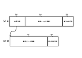
図3は、第一の無線端末宛ての下り制御情報と第二の無線端末宛ての下り制御情報とを概略的に示した図である。図3に示す例では、第一の無線端末宛ての下り制御情報DCI#1は、第二の無線端末(第一の無線端末にとって他端末とも称される)宛ての下り制御情報DCI#2に関する参照情報D10と、第一の無線端末(第一の無線端末にとって自端末とも称される)宛ての下りデータ信号の受信に必要な無線リソース情報D11と、第一の無線端末宛ての下り制御情報DCI#1の誤り検出処理に必要な誤り検出符号D12を有する。下り制御情報DCI#1の内容のうち、誤り検出符号D12は、第一の無線端末10Aに関する識別情報によりスクランブリングされており、第一の無線端末10Aに関する識別情報に基づいてデスクランブリングすることができるように構成される。下り制御情報DCI#1の内容のうち、参照情報D10と、無線リソース情報D11とは、第一の無線端末10Aに関する識別情報に基づくスクランブリングの対象外であってもよい。第一の無線端末10Aに関する識別情報は、RNTI(Radio Network Temporary Identifier)、C-RNTI(Cell RNTI)とも称されてよい。図3に例示する参照情報D10は、例えば、位置指定情報、関連付け情報、ポインタ情報、リンク情報などと称されてもよい。
図3に示す例において、第二の無線端末宛ての下り制御情報DCI#2は、第二の無線端末(第二の無線端末にとって自端末とも称される)宛ての下りデータ信号の受信に必要な無線リソース情報D21と、第二の無線端末宛ての下り制御情報DCI#2の誤り検出処理に必要な誤り検出符号D22を有する。下り制御情報DCI#2の内容のうち、誤り検出符号D22は、第二の無線端末10Bに関する識別情報によりスクランブリングされており、第二の無線端末10Bに関する識別情報に基づいてデスクランブリングすることができるように構成される。下り制御情報DCI#2の内容のうち、無線リソース情報D21は、第二の無線端末10Bに関する識別情報に基づくスクランブリングの対象外であってもよい。第二の無線端末10Bに関する識別情報は、RNTI(Radio Network Temporary Identifier)、C-RNTI(Cell RNTI)とも称されてよい。
参照情報D10は、制御領域内の無線リソースのうち、他端末宛ての下り制御情報がマッピングされた無線リソースの位置を示す。図3に示す例において、第一の無線端末宛ての下り制御情報DCI#1に格納された参照情報D10は、第二の無線端末宛ての下り制御情報DCI#2がマッピングされた制御領域内の位置を示す。これにより、第一の無線端末10Aは、第一の無線端末宛ての下り制御情報DCI#1に格納された参照情報に基づいて、第二の無線端末宛ての下り制御情報DCI#2を取得することができ、取得した下り制御情報DCI#2に格納された無線リソース情報D21に基づいて第二の無線端末宛ての下りデータ信号に対する受信処理を実行することができる。
図4は、参照情報の内容例を示す図である。図4に示す例では、参照情報D10は、他端末の下り制御情報がマッピングされた無線リソースの先頭の位置を示す開始位置情報D101と、当該無線リソースの長さを示すサイズ情報D102とを有する。
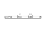
図5は、制御領域における無線リソースと下り制御情報の配置を概略的に示す図である。図5に示す例では、制御領域内の無線リソース(CCE: Control Channel Element)として、インデックス番号が0番から32番までの合計33個のCCEが存在する。第一の無線端末宛ての下り制御情報DCI#1は、インデックス番号が16番のCCEと17番のCCEとの集合に配置(マッピング)されている。第二の無線端末宛ての下り制御情報DCI#2は、インデックス番号が22番のCCEと23番のCCEとの集合に配置されている。
図5に示す例において、第一の無線端末宛ての下り制御情報DCI#1に格納される参照情報D10は、第二の無線端末宛ての下り制御情報DCI#2が配置されたCCEの位置を示す。参照情報D10は、例えば、第二の無線端末宛ての下り制御情報DCI#2が配置されたCCEの集合のうち先頭(図5において左側)のCCEのインデックス番号(図5の例において22番)を、開始位置情報D101として有する。図5に示す例によれば、制御領域内のCCEはインデックス番号が0番から32番の合計33個であり、6ビットで全てのインデックス番号が表現し得るため、開始位置情報D101のデータ長は6ビットあればよい。
参照情報D10は、例えば、第二の無線端末宛ての下り制御情報DCI#2が配置されたCCEの集合の長さ(図5の例において2)を、サイズ情報として有する。サイズ情報D102は、アグリゲーションレベル(Aggregation Level)と称されてもよい。アグリゲーションレベルは、例えば、レベル1、レベル2、レベル4、レベル8の4段階が存在するように構成されても良い。アグリゲーションレベルがレベル1の場合、下り制御情報がマッピングされるCCEの集合は長さ1である。アグリゲーションレベルがレベル2の場合、下り制御情報がマッピングされるCCEの集合は長さ2である。アグリゲーションレベルがレベル4の場合、下り制御情報がマッピングされるCCEの集合は長さ4である。アグリゲーションレベルがレベル8の場合、下り制御情報がマッピングされるCCEの集合は長さ8である。この例によれば、2ビットで全てのアグリゲーションレベルが表現し得るため、サイズ情報D102のデータ長は2ビットあればよい。
上述の如く、第一の無線端末10Aは、例えば、制御領域の無線リソースをブラインドサーチすることで、第一の無線端末宛ての下り制御情報DCI#1の検出に成功した場合、下り制御情報DCI#1における参照情報D10に基づいて、第二の無線端末宛ての下り制御情報DCI#2を取得することができる。別言すると、第一の無線端末10Aは、参照情報D10を用いることで、第二の無線端末宛ての下り制御情報DCI#2のブラインドサーチを省略することができる。そのため、第一の無線端末10Aは、ブラインドサーチに要する時間と比較して、第二の無線端末宛ての下り制御情報DCI#2の取得に要する時間を短縮することができる。しかも、参照情報は、例えば6ビット長の開始位置情報D101と、2ビット長のサイズ情報D102との合計8ビット長で済むため、非直交多元接続方式における干渉キャンセルに必要な情報の伝達のために増加するデータ量を抑制することができる。別言すると、上述の従来技術においては、第二の無線端末宛ての下りデータ信号を取得するための情報は、第二の無線端末宛ての下り制御情報と、第一の無線端末宛ての下り制御情報とで、重複して送受信されていたところ、実施例1によれば、このような重複を回避することができる。このような側面は、第五世代移動通信システムなどへの適用を検討されている非直交多元接続方式における、干渉キャンセルに必要な情報の伝送効率を向上させつつ、超高信頼・低遅延通信の機能要件を満たすうえで有用である。
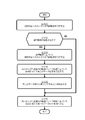
図6は、実施例1に係る無線端末10における処理の流れの一例を示す図である。図6に示す処理の流れは、例えば、図2に例示するサブフレームの制御領域において、自端末宛ての下り制御情報を探索(ブラインドサーチとも称される)することで、自端末宛ての下り制御情報の検出に成功した場合に、実行を開始するようにしてよい。なお、自端末宛ての下り制御情報の探索では、下り制御情報に添付されている誤り検出符号を、自端末に関する識別情報でデスクランブルし、デスクランブル後の誤り検出符号で下り制御情報に対する誤り検出が行われる。その結果、下り制御情報に治癒し得ない誤りが検出されなかった場合、無線端末10は、自端末宛ての下り制御情報の検出に成功したと判定する。一方、下り制御情報に治癒し得ない誤りが検出された場合、無線端末10は、当該下り制御情報は他端末宛ての下り制御情報であると判定すればよい。
無線端末10は、無線基地局20により送信された下りリンク信号から、自端末宛ての下り制御情報である第一の下り制御情報を取得する(S101)。図2に示す例によれば、処理S101において、無線端末10は、制御領域に配置された第一の下り制御情報DCI#1を取得する。そして、無線端末10は、第一の下り制御情報に参照情報が存在するかを判定する(S102)。
処理S102において、無線端末10は、例えば、処理S101で取得した第一の下り制御情報のデータ長に基づいて、参照情報が存在するか否かを判定しても良い。図3に示す例によれば、参照情報D10が格納されている下り制御情報DCI#1と、参照情報D10が格納されていない下り制御情報DCI#2とでは、少なくとも参照情報D10を格納する領域分において、データ長に差が生じる。したがって、処理S102において、無線端末10は、第一の下り制御情報のデータ長が参照情報を含む下り制御情報のデータ長に相当するか否かを判定することで、参照情報が存在するかを判定してもよい。あるいは、第一の下り制御情報は、参照情報を含む下り制御情報であるか否かを示すフォーマット情報を含んでもよい。すなわち、処理S102において、無線端末10は、第一の下り制御情報のフォーマット情報に基づいて、参照情報が存在するかを判定しても良い。
処理S102において、第一の下り制御情報に参照情報が存在すると判定した場合(S102でYES)、無線端末10は、無線基地局20により送信された下りリンク信号から、第一の下り制御情報から取得した参照情報に基づいて、他端末宛ての下り制御情報である第二の下り制御情報を取得する(S103)。図2に示す例によれば、無線端末10は、第一の下り制御情報DCI#1から取得した参照情報に基づいて、他端末宛ての下り制御情報DCI#2を取得する。
処理S103において、無線端末10は、第二の下り制御情報のうち、誤り検出符号については無視しても良い。なぜならば、上述の如く、第二の下り制御情報のうち、誤り検出符号については、第二の下り制御情報の本来の宛先である他端末に関する識別情報に基づいてスクランブリングがかかっており、当該識別情報を用いてデスクランブリングしない限り無意味な内容だからである。
なお、処理S103において、無線端末10は、第二の下り制御情報の誤り検出符号を無視する場合、第二の下り制御情報の内容について誤り検出を実行しなくてもよい。ここで、第一の下り制御情報に参照情報が含まれているということは、非直交多元接続方式における干渉除去処理の実行を、無線基地局20が無線端末10に対して指示していることを意味する。別言すると、無線基地局20は、SN比が高い無線端末10に対して、参照情報を含む第一の下り制御情報を送信する。なぜならば、直交多元接続方式では、無線基地局20は、SN比が高い無線端末10に対して小送信電力を割当て、SN比が低い無線端末10に対して大送信電力を割当てるためである。
一般的に、SN比が高いということは、無線基地局20の近傍に無線端末10が存在し、所望信号に対する雑音の影響度合いが低いことを意味する。同様に、SN比が高い無線端末10にとって、他端末宛ての制御情報に対する雑音の影響度合いも低い。そのため、SN比が高い無線端末10は、無線基地局20により送信された下りリンク信号の制御領域に格納された他端末宛ての下り制御情報を受信する場合、雑音の影響度合いを無視し得る。このことは、非直交多元接続方式における干渉キャンセルに必要とされる情報を削減するという側面を有する。別言すると、実施例1に係る無線通信システム1では、他端末宛ての下り制御情報のCRCをデスクランブルするための識別情報を、無線端末に通知しなくてもよい。他端末宛ての下り制御情報のCRCのデスクランブルに、他端末のRNTI、C-RNTIなどの識別情報が必要とされる場合、実施例1に係る無線通信システムでは、当該識別情報を格納するための領域である例えば16ビット長の領域を省略することができる。
無線端末10は、第二の下り制御情報に格納された無線リソース情報を取得し、第二の下り制御情報から取得した無線リソース情報に基づいて他端末宛ての下りデータ信号である第二の下りデータ信号を受信する(S104)。図2に示される例によれば、処理S104において、無線端末10は、第二の下り制御情報DCI#2から取得した無線リソース情報に基づいて、下りデータ用無線リソース#1に多重された他端末宛ての下りデータ信号を受信する。
図7は、第二の下り制御情報の内容例を示す図である。図7に例示する第二の下り制御情報は、1ビットの第一情報要素(Resource allocation header)D201と、下りリンク信号のシステム帯域に応じて定まるビット長の第二情報要素(Resource block assignment for RA Type 0)D202と、2ビットの第三情報要素(TPC for PUCCH)D203と、2ビットの第四情報要素(Downlink Assignment Index)D204と、無線端末と無線基地局との双方向無線通信方式として時分割複信(TDD: Time Division Duplex)を用いるか周波数分割複信(FDD: Frequency Division Duplex)を用いるかに応じて定まるビット長の第五情報要素(HARQ Process)D205と、1ビットの第六情報要素(Transport block to codeword swap flag)D206と、5ビットの第七情報要素(MCS for Transport Block 1)D207と、1ビットの第八情報要素(NDI for Transport Block 1)D208と、2ビットの第九情報要素(RV for Transport Block 1)D209と、5ビットの第十情報要素(MCS for Transport Block 2)D210と、1ビットの第十一情報要素(NDI for Transport Block 2)D211と、2ビットの第十二情報要素(RV for Transport Block 2)D212と、アンテナポート数に応じて定まるビット長の第十三情報要素(Precoding information)D213とを有する。図7に例示される情報要素D201ないしD213のうち、図3に示す第二の下り制御情報DCI#2の無線リソース情報D21に相当する情報要素は、第六情報要素D206から第十三情報要素D213までの8個の情報要素である。無線端末10は、図7に例示する第六情報要素D206から第十三情報要素D213までの8個の情報要素に基づいて、下りデータ用無線リソース#1に多重された他端末宛ての下りデータ信号を受信してもよい。ただし、本開示は、図7に例示する第二の下り制御情報の内容に限定されるものではない。図7に例示する各情報要素の趣旨については、上述の非特許文献1ないし19に示される技術常識が援用される。
無線端末10は、処理S104で取得した第二の下りデータ信号に基づいて、下りデータ用無線リソース#1の下りリンク信号から、干渉成分を除去する処理を実行する(S105)。
無線端末10は、処理S105で干渉成分を除去した後の下りリンク信号について、第一の下り制御情報の無線リソース情報に基づいて、自端末宛ての下りデータ信号である第一の下りデータ信号を受信する(S106)。これにより、無線端末10は、非直交多元接続方式により同一の無線リソースに多重された他端末宛ての下りデータ信号による干渉成分による影響を抑制しつつ、自端末宛ての下りデータ信号を受信することができる。
一方、処理S102において、第一の下り制御情報に参照情報が存在しないと判定した場合(S102でNO)、無線端末10は、上述の処理S103ないし処理S105の実行を省略する。なぜならば、第一の下り制御情報に参照情報が存在しないということは、非直交多元接続方式における干渉除去処理の実行を、無線基地局20が無線端末10に対して指示していないことを意味するためである。この場合、無線端末10は、処理S106において、非直交多元接続方式における干渉除去が行われていない下りリンク信号について、第一の下り制御情報の無線リソース情報に基づき、自端末宛ての下りデータ信号である第一の下りデータ信号を受信する(S106)。
以上が、実施例1に係る無線端末10における処理の流れの一例である。なお、実施例1は、第一の下り制御情報に一つの参照情報が格納されている場合に限定されない。例えば、一つの第一の下り制御情報に、一以上の参照情報が格納されていても良い。その場合、図6に示す例において、第一の下り制御情報に格納されている参照情報の個数の分だけ、処理S103ないし処理S105を実行すればよい。
図8は、実施例1に係る無線基地局20における処理の流れの一例を示す図である。図8に示す処理の流れは、例えば、図2に例示するような下りリンク信号を生成する際に、実行を開始しても良い。
無線基地局20は、非直交多元接続方式により、同じ無線リソースに下りデータ信号が多重される第一の無線端末と第二の無線端末とを選択する(S201)。処理S201において、無線基地局20は、無線端末毎の送信バッファに下りデータ(ダウンリンクデータ、DLデータなどとも称される)が存在する無線端末のうち、SN比が高い無線端末を第一の無線端末として選択し、SN比が低い無線端末を第二の無線端末として選択しても良い。SN比が高いか低いかは、例えば、SN比に相当する値と閾値とを比較することで、判定しても良い。あるいは、無線端末同士のSN比に相当する値を比較することで、SN比が相対的に高いか低いかを判定しても良い。
処理S201において参照される各無線端末10のSN比は、無線端末10からの測定結果報告(Measurement reportとも称される)などに基づいて、無線基地局20に把握されているものとする。なお、無線端末10からの測定結果報告にはSN比の値が格納されている必要は必ずしもなく、無線端末10において観測される無線基地局20からの下りリンク信号のSN比に比例して変動する値(「SN比に相当する値」とも称される)であれば何でも良い。別言すると、実施例1に係る無線基地局20は、SN比が高い又はSN比が低いという判定を、SN比の値とは異なる他の値に基づいて判定しても良い。本開示における「SN比に相当する値」は、例えば、CQI(Channel Quality Indicator)と称されても良いし、CSI(Channel Status Information)と称されても良いし、符号化レート(Coding Rate)と称されても良いし、変調方式(MCS: Modulation Coding Scheme)と称されても良いし、MCSインデックスと称されても良いし、TBS(Transport Block Size)と称されても良い。例えば、無線端末のSN比が高いほど、符号化レートが高い変調方式(別言すると、MCSインデックスの値が大きい変調方式)が選択され、TBSが大きくなる。一方、無線端末のSN比が低いほど符号化レートが低い変調方式(別言すると、MCSインデックスの値が小さい変調方式)が選択され、TBSが小さくなる。
処理S201において、無線基地局20は、一以上の第一の無線端末を選択しても良いし、一以上の第二の無線端末を選択しても良い。別言すると、実施例1において、第一の無線端末及び第二の無線端末の個数を限定することは意図していない。
無線基地局20は、第二の無線端末宛ての下り制御情報である第二の下り制御情報に対して割当てる、制御領域の無線リソース(第二の無線リソースとも称される)を選択する(S202)。処理S202において、無線基地局20は、第二の無線端末の測定結果報告に示される値などに基づいて、下り制御情報に割当てる無線リソースの個数である連結数(アグリゲーションレベルとも称される)を決定し、連結数に応じた無線リソースを選択する。図5に示す例では、第二の無線端末宛ての第二の下り制御情報DCI#2に対して、無線リソースCCE[22]と無線リソースCCE[23]との集合が選択されている。すなわち、この例での連結数は2である。
無線基地局20は、第二の無線リソースの位置を示す参照情報を生成する(S203)。処理S203において、無線基地局20は、処理S202で選択した無線リソースの集合における先頭の無線リソースのインデクス番号を有する開始位置情報と、処理S202で決定した連結数を有するサイズ情報とを、参照情報に格納しても良い。
無線基地局20は、処理S203で生成した参照情報を、第一の無線端末宛ての下り制御情報である第一の下り制御情報に格納する(S204)。その結果、図3に例示するような、参照情報を有する第一の下り制御情報DCI#1が生成される。
無線基地局20は、第一の無線端末宛ての第一の下り制御情報DCI#1と、第二の無線端末宛ての第二の下り制御情報DCI#2とを、下りリンク信号の制御領域に配置する(S205)。その際、第一の下り制御情報DCI#1の誤り検出符号D12は、第一の下り制御情報DCI#1に対応する第一の無線端末に関する識別情報でスクランブルした形式で配置される。第二の下り制御情報DCI#2の誤り検出符号D22は、第二の下り制御情報DCI#2に対応する第二の無線端末に関する識別情報でスクランブリングした形式で配置される。
無線基地局20は、第一の無線端末宛ての下りデータ信号である第一の下りデータ信号と、第二の無線端末宛ての下りデータ信号である第二の下りデータ信号とを、非直交多元接続方式により、下りリンク信号のデータ領域に多重する(S206)。その際、第一の下りデータ信号に対しては、第二の下りデータ信号に割当てられた送信電力よりも小さい送信電力が割当てられる。別言すると、第二の下りデータ信号に対しては、第一の下りデータ信号に割当てられた送信電力よりも大きい送信電力が割当てられる。ここで、第一の無線端末は、上述の如く、第二の無線端末よりもSN比が高い無線端末である。また、処理S206により、図2に例示するような、下りリンク信号が生成される。なお、図2に示す例では、説明の簡略化のため、第一の下りデータ信号と第二の下りデータ信号とが多重される下りデータ用無線リソース#1と、第一の下りデータ信号に関連する第一の下り制御情報DCI#1と、第二の下りデータ信号に関連する第二の下り制御情報DCI#2とが図示され、その他は省略されている。下りリンク信号の詳細な構造については、上述の非特許文献1ないし19を参照されたい。
無線端末20は、生成された下りリンク信号を、図1に例示するような無線サービスのエリア30に向けて、送信する(S207)。
以上が、実施例1に係る無線基地局20における処理の流れの一例である。
実施例1によれば、他端末宛ての下り制御情報が配置された無線リソースの位置を示す情報を、下り制御情報に追加して送信するため、他端末の識別情報に基づいてブラインドサーチする動作と比較すると、他端末宛ての下り制御情報を取得するまでの時間を短縮することができる。しかも、他端末の識別情報に関する情報を下り制御情報に追加して通知することを省略し得るため、そのぶん、干渉成分に関する情報を圧縮することができる。また、他端末の識別情報に基づくデスクランブリング処理を省略し得るため、処理時間を短縮することができる。この様な作用は、干渉成分に関する情報の伝送効率を向上させつつ、超高信頼・低遅延通信を実現する上で、有用である。
<実施例2> 図9は、実施例2に係る参照情報の内容例を示す図である。図9に例示する参照情報は、実施例1に係る参照情報の内容例に加え、さらに第二の誤り検出符号D103を有する。第二の誤り検出符号D103は、他端末宛ての下り制御情報の誤り検出符号であって、他端末の識別情報に基づいてスクランブリングされる前の誤り検出符号である。
実施例2では、無線端末10は、参照情報に基づいて他端末宛ての下り制御情報を取得した場合、参照情報から取得した第二の誤り検出情報に基づいて、当該取得した他端末宛ての下り制御情報に対する誤り検出を行うことができる。
つぎに、実施例2に係る無線端末10における処理の流れについて、簡潔に説明する。実施例2に係る無線端末10における処理の流れは、図6に例示する実施例1に係る無線端末10における処理の流れと同様であるため、図6に示す例を流用して説明する。すなわち、図6に示す処理S103において、無線端末10は、参照情報から開始位置情報D101とサイズ情報D102とを取得し、開始位置情報D101とサイズ情報D102とに基づいて他端末宛ての第二の下り制御情報を取得する。実施例2に係る処理S103では、さらに、無線端末10は、参照情報から取得される第二の誤り検出符号D103に基づいて、第二の下り制御情報に対する誤り検出を行う。これにより、実施例2に係る無線端末10は、第二の誤り検出符号D103に基づいて、第二の下り制御情報の信頼性を判定することができる。
実施例2に係る処理S103において、無線端末10は、第二の誤り検出符号D103に基づく誤り検出により、第二の下り制御情報に訂正し得ない誤りを検出した場合、処理S104ないし処理S105の処理を省略しても良い。処理S104ないし処理S105の処理を省略した結果、処理S106において、無線端末10は、自端末宛ての第一の下りデータ信号の受信に失敗するかもしれない。自端末宛ての第一の下りデータ信号の受信に失敗した場合は、無線基地局20に対して、第一の下りデータ信号の再送を依頼すればよい。
以上が、実施例2に係る無線端末10における処理の流れである。なお、図6に示す処理の流れのうち、上述の実施例2に係る無線端末10における処理の流れとして説明していない処理については、実施例1と同様であるため重複した説明を省略したことによる。
つぎに、実施例2に係る無線基地局20における処理の流れについて、簡潔に説明する。実施例2に係る無線基地局20における処理の流れは、図8に例示する実施例1に係る無線基地局20における処理の流れと同様であるため、図8に示す例を流用して説明する。すなわち、図8に示す処理S203において、実施例2に係る無線基地局20は、第二の無線リソースの位置を示す参照情報を生成するだけでなく、さらに、第二の無線端末宛ての下り制御情報の誤り検出に用いられる誤り検出符号である第二の誤り検出符号を、参照情報に格納する。図3に示す例によれば、第二の誤り検出符号は、第二の無線端末宛ての下り制御情報DCI#2の無線リソース情報D21に対する誤り検出に用いられる。ただし、第二の誤り検出符号は、第二の無線端末宛ての下り制御情報DCI#2に格納される誤り検出符号D22とは異なり、第二の無線端末に関する識別情報によるスクランブリングは行われていない。
処理S204以降は、実施例1と同様であるため説明を省略する。
以上が、実施例2に係る無線基地局20における処理の流れである。なお、図8に示す処理の流れのうち、上述の実施例2に係る無線基地局20における処理の流れとして説明していない処理については、実施例1と同様であるため重複した説明を省略したことによる。
実施例2によれば、他端末宛ての下り制御情報の誤り検出符号が、自端末宛ての下り制御情報に追加されて通知されるため、無線端末10は、他端末の識別情報を用いて他端末宛ての下り制御情報をブラインドサーチする動作と比較すると、他端末宛ての下り制御情報に対する誤り検出の結果を得るまでの時間を短縮することができる。この様な作用は、干渉成分に関する情報の伝送効率を向上させつつ、超高信頼・低遅延通信を実現する上で、有用である。
<実施例3> 図10は、実施例3に係る参照情報の内容例を示す図である。図10に例示する参照情報は、図9に示す実施例2に係る参照情報と同様に、実施例1に係る参照情報の内容例に加え、さらに第三の誤り検出符号D104を有する。第三の誤り検出符号D104は、第二の誤り検出符号D103とは異なり、他端末宛ての下り制御情報の一部の領域に関する誤り検出符号である。図7に例示するように、下り制御情報には様々なパラメータが設定されている。しかし、非直交多元接続方式により多重された他端末宛ての下りデータ信号による干渉成分を除去するために必要な下り制御情報のパラメータは、図7に例示されるパラメータの全てではなく一部である。ゆえに、実施例3では、干渉成分の推定に必要なパラメータの集合に対して生成された誤り検出符号が、第三の誤り符号D104として、参照情報に格納される。これにより、下り制御情報の全体に対する誤り検出符号である第二の誤り検出符号D103よりも、さらに誤り検出符号の符号長を圧縮することができる。
実施例3に係る無線端末10及び無線基地局20における処理の流れは、実施例2と同様である。ただし、実施例3に係る無線基地局20は、第三の誤り検出符号D104を生成する際に、上述の趣旨に沿う様に処理を行えばよい。例えば、実施例3に係る無線基地局20は、第一の無線端末10A宛ての第一の下り制御情報を生成する際に、第二の無線端末10B宛ての第二の下り制御情報の全てではなく、干渉成分の推定に必要なパラメータの集合に基づいて、第三の誤り検出符号D104を生成すればよい。干渉成分の推定に必要なパラメータの集合の例としては、例えば、図7に例示される第六情報要素D206から第十三情報要素D213までの8個の情報要素である。
実施例3に係る無線端末10も、第三の誤り検出符号D104に基づいて誤り検出を行う際に、上述の趣旨に沿う様に処理を行えばよい。例えば、実施例3に係る第一の無線端末10Aは、第三の誤り検出符号D104に基づく誤り検出を行う際に、参照情報に基づいて取得した第二の下り制御情報の全てに対して誤り検出を行うのではなく、干渉成分の推定に必要なパラメータの集合に対して誤り検出を行えばよい。
実施例3によれば、第三の誤り検出符号D104は、下り制御情報の全体に対する誤り検出符号である第二の誤り検出符号D103よりも、さらに誤り検出符号の符号長を圧縮することができる。この様な作用は、干渉成分に関する情報の伝送効率を向上させつつ、超高信頼・低遅延通信を実現する上で、さらに有用である。
<変形例1> 図11は、変形例1に係る参照情報の内容例を示す図である。図11に例示する参照情報は、2ビットの第一情報要素(他端末DCIマッピング情報数)D220と、3個の第二情報要素(他端末情報[1]ないし他端末情報[3])D230,D240,D250とを有する。第二情報要素D230,D240,D250の各々は、2ビットの第一副情報要素(Aggregation Level Index)D231と、6ビットの第二副情報要素(開始CCE)D232とを有し、これらの副情報要素により、関連する他端末宛ての下り制御情報が配置された無線リソースの位置を示す。別言すると、第一副情報要素D231は、図4に例示するサイズ情報D102に相当する。第二副情報要素D232は、図4に例示する開始位置情報D101に相当する。図11の例示において、第一情報要素D220は、参照情報に格納されている第二情報要素D230,D240,D250の個数を示す。図11の例示では、3個の第二情報要素D230,D240,D250が格納されている例を示しているが、変形例1はこれに限定されない。例えば、変形例1に係る参照情報は、一個の第二情報要素を有しても良い。
<変形例2> 上述した各実施例及び変形例において例示した参照情報D10は、開始位置情報D101とサイズ情報D102とを備えている。ただし、本願における参照情報D10は、これに限らず、例えば開始位置情報D101を含むがサイズ情報D102を含まないように構成することも可能である。例えば、第二の無線端末宛ての下り制御情報が配置される無線リソースのサイズを固定的なものとして定義された無線通信システム1においては、サイズ情報D102を省略し得る。これにより、参照情報をさらに圧縮することが出来る。この様な作用は、干渉成分に関する情報の伝送効率を向上させつつ、超高信頼・低遅延通信を実現する上で、さらに有用である。
<ハードウェア構成> 最後に、上述の実施例1ないし実施例3に用いられる各装置のハードウェア構成について、簡単に説明する。図12は、無線通信システム1における無線端末10と無線基地局20とのハードウェア構成の一例を示す図である。
図12に示す無線端末10は、無線通信回路101、処理回路102、メモリ103を有する。なお、図12に示す無線端末10では、アンテナの図示を省略している。また、無線端末10は、液晶ディスプレイなどの表示装置や、タッチパネルなどの入力装置や、リチウムイオン二次電池(lithium-ion rechargeable battery)などのバッテリを備えてもよい。
無線通信回路101は、下りリンク(ダウンリンクとも称される)において、処理回路102からのベースバンド信号を受けて、ベースバンド信号から所定の出力レベルの無線信号を生成し、アンテナを介して無線信号を空間に放射するように構成される。また、無線通信回路101は、上りリンク(アップリンクとも称される)において、アンテナから入力される無線信号を受信し、無線信号をベースバンド信号に変換し、処理回路102にベースバンド信号を供給するように構成される。無線通信回路101は、伝送回路を介して処理回路102と通信可能に接続され得る。伝送回路としては、例えば、M-PHY、Dig-RFなどの規格に準拠した伝送回路が挙げられる。上述のように、無線通信回路101は、無線基地局20との無線通信を行う機能を有する通信部(送受信部、第一の送受信部とも称される)としての側面を有する。
処理回路102は、ベースバンド信号処理を行うように構成さる回路である。処理回路102は、アップリンクにおいて、無線通信システムにおけるプロトコルスタックに基づいてベースバンド信号を生成し、無線通信回路101にベースバンド信号を出力するように構成される。また、処理回路102は、ダウンリンクにおいて、無線通信回路101から入力されたベースバンド信号に対して、無線通信システムにおけるプロトコルスタックに基づいて復調・復号などの受信処理を行うように構成される。別言すると、アップリンクにおいて、処理回路102は、無線通信の機能を複数のレイヤに分割したプロトコルスタックの手順に従って、受信装置としての無線基地局20に向けて、上位レイヤから下位レイヤへと送信データを順次処理して、無線通信回路101を介して送信する回路としての側面を有する。また、ダウンリンクにおいて、処理回路102は、無線通信の機能を複数のレイヤに分割したプロトコルスタックの手順に従って、無線通信回路101を介して受信した無線信号を、下位レイヤから上位レイヤへと順次処理する回路としての側面を有する。ここで、ダウンリンクにおいて、無線通信回路101からベースバンド信号の入力を受けることは、無線通信回路101を介して無線基地局20からの無線信号を受信するという側面を有する。
処理回路102は、例えば、メモリ103に格納されたプログラムを読みだして実行することで、上述の各種の実施例に係る無線端末10の動作を実現する演算装置であってもよい。別言すると、処理回路102は、図6に例示する無線端末10における処理の流れの実行主体としての側面を有する。処理回路102として、例えば、CPU(Central Processing Unit)、MPU(Micro Processing Unit)、DSP(Digital Signal Processor)やFPGA(Field Programmable Gate Array)などが挙げられる。なお、処理回路102は、二以上のコアを含むマルチコアプロセッサであっても良い。また、処理回路102は、無線通信システムのプロトコルスタックにおける各レイヤに応じて、二以上の処理回路102を実装してもよい。例えば、MAC(Medium Access Control)レイヤに属するMACエンティティとしての処理を実行する処理回路102と、RLC(Radio Link Control)レイヤに属するRLCエンティティとしての処理を実行する処理回路102と、PDCP(Packet Data Convergence Protocol)レイヤに属するPDCPエンティティとしての処理を実行する処理回路102とを、個別に実装してもよい。処理回路102は、C-CPUとも称される。無線端末10は、処理回路102の他に、アプリケーションを実行するA-CPUとも称されるプロセッサ回路を実装してもよい。なお、処理回路102は、A-CPUとも称されるプロセッサ回路とともに1チップで実装してもよいし、個別のチップとして実装してもよい。処理回路102は、無線端末10の動作を制御する機能を有する制御部(第一の制御部とも称される)としての側面を有する。
メモリ103は、処理回路102で実行されるベースバンド信号処理に係るデータやプログラムを記憶保持するように構成される回路である。メモリ103は、不揮発性記憶装置と揮発性記憶装置の両方あるいは一方を少なくとも含んで構成される。たとえば、RAM(Random Access Memory)、ROM(Read Only Memory)、SSD(Solid State Drive)、HDD(Hard Disk Drive)などが挙げられる。図12において、メモリ103は、主記憶装置及び補助記憶装置などの各種記憶装置を総称したものである。なお、メモリ103は、処理回路102と同様に、無線通信システムのプロトコルスタックにおける各レイヤに応じて、二以上のメモリ103を実装してもよい。例えば、MACレイヤに属するMACエンティティとしての処理に用いられるメモリ103と、RLCレイヤに属するRLCエンティティとしての処理に用いられるメモリ103と、PDCPレイヤに属するPDCPエンティティとしての処理に用いられるメモリ103とを、個別に実装してもよい。
図12に示す無線基地局20は、無線通信回路201、処理回路202、メモリ203、有線通信回路204、を有する。なお、図12に示す無線基地局20では、アンテナの図示を省略している。
無線通信回路201は、ダウンリンクにおいて、処理回路202からのベースバンド信号を受けて、ベースバンド信号から所定の出力レベルの無線信号を生成し、アンテナを介して無線信号を空間に放射するように構成される。また、無線通信回路201は、アップリンクにおいて、アンテナから入力される無線信号を受信し、無線信号をベースバンド信号に変換し、処理回路202へベースバンド信号を供給するように構成される。無線通信回路201は、CPRI(Common Public Radio Interface)などの伝送路を介して処理回路202と通信可能に接続させることも可能であり、RRH(Remote Radii Head)、RRE(Remote Radio Equipment)とも称され得る。また、無線通信回路201と処理回路202との組み合わせは、一対一に限定されるものではなく、一つの無線通信回路201に複数の処理回路202を対応付けたり、複数の無線通信回路201を一つの処理回路202に対応付けたり、複数の無線通信回路201を複数の処理回路202に対応付けることも可能である。上述のように、無線通信回路201は、無線端末10との無線通信を行う機能を有する通信部(送受信部、第二の送受信部とも称される)としての側面を有する。
処理回路202は、ベースバンド信号処理を行うように構成さる回路である。処理回路202は、ダウンリンクにおいて、無線通信システムにおけるプロトコルスタックに基づいてベースバンド信号を生成し、無線通信回路201にベースバンド信号を出力するように構成される。また、処理回路202は、アップリンクにおいて、無線通信回路201から入力されたベースバンド信号に対して、無線通信システムにおけるプロトコルスタックに基づいて復調・復号などの受信処理を行うように構成される。別言すると、ダウンリンクにおいて、処理回路202は、無線通信の機能を複数のレイヤに分割したプロトコルスタックの手順に従って、受信装置としての無線端末10宛ての送信データを、上位レイヤから下位レイヤへと順次処理して、無線通信回路201を介して送信する回路としての側面を有する。また、アップリンクにおいて、処理回路202は、無線通信の機能を複数のレイヤに分割したプロトコルスタックの手順に従って、無線通信回路201を介して受信した無線信号を、下位レイヤから上位レイヤへと順次処理する回路としての側面を有する。ここで、アップリンクにおいて、無線通信回路201からベースバンド信号の入力を受けることは、無線通信回路201を介して無線端末10からの無線信号を受信するという側面を有する。
処理回路202は、例えば、メモリ203に格納されたプログラムを読みだして実行することで、上述の各種の実施例に係る無線基地局20の動作を実現する演算装置であってもよい。別言すると、処理回路202は、図8に例示する無線基地局20における処理の流れの実行主体としての側面を有する。処理回路202として、例えば、CPU(Central Processing Unit)、MPU(Micro Processing Unit)、DSP(Digital Signal Processor)やFPGA(Field Programmable Gate Array)などが挙げられる。なお、処理回路202は、二以上のコアを含むマルチコアプロセッサであっても良い。また、処理回路202は、無線通信システムのプロトコルスタックにおける各レイヤに応じて、二以上の処理回路202を実装してもよい。例えば、MACレイヤに属するMACエンティティとしての処理を実行する処理回路202と、RLCレイヤに属するRLCエンティティとしての処理を実行する処理回路202と、PDCPレイヤに属するPDCPエンティティとしての処理を実行する処理回路202とを、個別に実装してもよい。上述のように、処理回路202は、無線基地局20の動作を制御する機能を有する制御部(第二の制御部とも称される)としての側面を有する。
メモリ203は、処理回路202で実行されるベースバンド信号処理に係るデータやプログラムを記憶保持するように構成される回路である。メモリ203は、不揮発性記憶装置と揮発性記憶装置の両方あるいは一方を少なくとも含んで構成される。たとえば、RAM(Random Access Memory)、ROM(Read Only Memory)、SSD(Solid State Drive)、HDD(Hard Disk Drive)などが挙げられる。図12において、メモリ203は、主記憶装置及び補助記憶装置などの各種記憶装置を総称したものである。なお、メモリ203は、処理回路202と同様に、無線通信システムのプロトコルスタックにおける各レイヤに応じて、二以上のメモリ203を実装してもよい。例えば、MACレイヤに属するMACエンティティとしての処理に用いられるメモリ203と、RLCレイヤに属するRLCエンティティとしての処理に用いられるメモリ203と、PDCPレイヤに属するPDCPエンティティとしての処理に用いられるメモリ203とを、個別に実装してもよい。
有線通信回路204は、他の装置へ出力可能なフォーマットのパケットデータに変換して他の装置へ送信したり、他の装置から受信したパケットデータからデータなどを抽出して、メモリ203や処理回路202などに出力したりする。他の装置の例としては、他の無線基地局やMME(Mobility Management Entity)やSGW(Serving Gateway)などがあり得る。MMEやSGWはコアノードとも称され、コアノードとの通信に用いられる論理的な通信インタフェースはS1インタフェースとも称される。他の無線基地局装置との通信に用いられる論理的な通信インタフェースはX2インタフェースとも称される。
以上の詳細な説明により、実施形態の特徴点及び利点は明らかになるであろう。これは、特許請求の範囲がその精神及び権利範囲を逸脱しない範囲で前述のような実施形態の特徴点及び利点にまで及ぶことを意図するものである。また、当該技術分野において通常の知識を有する者であれば、あらゆる改良及び変更に容易に想到できるはずである。したがって、発明性を有する実施形態の範囲を前述したものに限定する意図はなく、実施形態に開示された範囲に含まれる適当な改良物及び均等物に拠ることも可能である。例えば、本明細書に開示の各工程は、必ずしも処理の流れの一例として説明された順序に沿って時系列に処理する必要はなく、特許請求の範囲に記載された本発明の要旨の範囲内において、工程の順序を入れ替えてもよく、あるいは複数の工程を並列的に実行してもよい。なお、以上の詳細な説明で明らかにされる第五世代移動通信システムに生じ得る事情は、第五世代移動通信システムを一側面から検討した場合に見出し得るものであり、他の側面から検討した場合には、他の事情が見出され得ることに留意されたい。別言すると、本発明の特徴点及び利点は、以上の詳細な説明に明記された事情を解決する用途に限定されるものではない。
最後に、本開示の実施形態の構成は、本発明の技術的思想を具体化するための一例を示したものであり、本発明をこの実施形態の構成に限定することを意図するものではなく、特許請求の範囲に含まれるその他の実施形態にも等しく適用し得るものである。例えば、本開示における用語は、今後の第五世代移動通信システムの仕様策定において、名称が変更され得ることに留意されたい。
1 無線通信システム
10 無線端末
101 無線通信回路
102 処理回路
103 メモリ
20 無線基地局
201 無線通信回路
202 処理回路
203 メモリ
204 有線通信回路
30 エリア
10 無線端末
101 無線通信回路
102 処理回路
103 メモリ
20 無線基地局
201 無線通信回路
202 処理回路
203 メモリ
204 有線通信回路
30 エリア
Claims (15)
- 非直交多元接続方式による無線サービスを提供可能な無線通信システムであって、
無線基地局と、複数の無線端末とを備え、
前記無線基地局は、
前記複数の無線端末のうち、非直交多元接続方式により同じ下り無線リソースに下りデータ信号を多重する第一の無線端末と第二の無線端末とを選択する処理と、
前記第一の無線端末宛ての第一の下りデータ信号に関する下り制御情報である第一の下り制御情報に、前記第二の無線端末宛ての第二の下りデータ信号に関する下り制御情報である第二の下り制御情報が配置される無線リソースの位置を示す参照情報を格納する処理と、
前記第一の下り制御情報と、前記第二の下り制御情報と、前記第一の下りデータ信号と、前記第二の下りデータ信号とが配置された下りリンク信号を、無線通信回路を用いて送信する処理と、
を実行する処理回路を備え、
前記第一の無線端末は、
前記無線基地局により送信された前記下りリンク信号から、前記第一の無線端末宛ての第一の下り制御情報を取得する処理と、
前記第一の下り制御情報から取得した前記参照情報に基づいて、前記第二の無線端末宛ての前記第二の下り制御情報を取得する処理と、
前記第二の下り制御情報に基づいて、前記第二の無線端末宛ての前記第二の下りデータ信号を受信する処理と、
前記第二の下りデータ信号による干渉成分を、前記下りリンク信号から除去する処理と、
前記干渉成分の除去後の前記下りリンク信号から、前記第一の下り制御情報に基づいて、前記第一の無線端末宛ての前記第一の下りデータ信号を受信する処理と、
を実行する処理回路を備える、
ことを特徴とする無線通信システム。 - 請求項1に記載の無線通信システムであって、
前記下りリンク信号は、少なくとも周波数軸と時間軸とで定義された複数の無線リソースを有しており、
前記複数の無線リソースのうち、前記時間軸において前方に位置する無線リソースの集合により制御領域が形成され、前記時間軸において前記制御領域よりも後方に位置する無線リソースの集合によりデータ領域が形成されており、
前記制御領域内の無線リソースの各々は、前記制御領域内の無線リソースに対して付与されたリソース番号で区別可能であり、
前記参照情報は、前記制御領域において前記第二の下り制御情報が配置される一以上の無線リソースのうち一の無線リソースに対応する前記リソース番号と、前記第二の下り制御情報が配置される無線リソースの個数を示す連結数とを有しており、
前記第一の無線端末の前記処理回路は、前記参照情報から取得した前記リソース番号と前記連結数とに基づいて、前記第二の無線端末宛ての前記第二の下り制御情報を取得する、
ことを特徴とする無線通信システム。 - 請求項1または2に記載の無線通信システムであって、
前記無線基地局の前記処理回路は、前記第一の下り制御情報に格納される前記参照情報に、前記第二の下り制御情報の誤り検出が可能な誤り検出符号を追加し、
前記第一の無線端末の前記処理回路は、前記第一の下り制御情報から取得した前記参照情報に含まれる前記誤り検出符号を用いて、前記参照情報に基づいて取得した前記第二の下り制御情報の誤り検出を行う、
ことを特徴とする無線通信システム。 - 請求項3に記載の無線通信システムであって、
前記誤り検出符号は、前記第二の下り制御情報のうち、前記第二の無線端末宛ての前記第二の下りデータ信号の受信に関するパラメータに基づいて生成されたものであり、
前記第一の無線端末は、前記参照情報から取得した前記誤り検出符号を用いて、前記第二の下り制御情報のうち、前記第二の下りデータ信号の受信に関するパラメータの誤り検出を行う、
ことを特徴とする無線通信システム。 - 請求項1ないし4の何れかに記載の無線通信システムであって、
前記第一の無線端末は、前記第二の無線端末よりもSN比が高い無線端末である、
ことを特徴とする無線通信システム。 - 非直交多元接続方式により複数の無線端末との通信が可能な無線基地局であって、
前記複数の無線端末のうち、非直交多元接続方式により同じ下り無線リソースに下りデータ信号を多重する第一の無線端末と第二の無線端末とを選択する処理と、
前記第一の無線端末宛ての第一の下りデータ信号に関する下り制御情報である第一の下り制御情報に、前記第二の無線端末宛ての第二の下りデータ信号に関する下り制御情報である第二の下り制御情報が配置される無線リソースの位置を示す参照情報を格納する処理と、
前記第一の下り制御情報と、前記第二の下り制御情報と、前記第一の下りデータ信号と、前記第二の下りデータ信号とが配置された下りリンク信号を、無線通信回路を用いて送信する処理と、
を実行する処理回路を備える、
ことを特徴とする無線基地局。 - 請求項6に記載の無線基地局であって、
前記下りリンク信号は、少なくとも周波数軸と時間軸とで定義された複数の無線リソースを有しており、
前記複数の無線リソースのうち、前記時間軸において前方に位置する無線リソースの集合により制御領域が形成され、前記時間軸において前記制御領域よりも後方に位置する無線リソースの集合によりデータ領域が形成されており、
前記制御領域内の無線リソースの各々は、前記制御領域内の無線リソースに対して付与されたリソース番号で区別可能であり、
前記参照情報は、前記制御領域において前記第二の下り制御情報が配置される一以上の無線リソースのうち一の無線リソースに対応する前記リソース番号と、前記第二の下り制御情報が配置される無線リソースの個数を示す連結数とを有する、
ことを特徴とする無線基地局。 - 請求項6または7に記載の無線基地局であって、
前記処理回路は、前記第一の下り制御情報に格納される前記参照情報に、前記第二の下り制御情報の誤り検出が可能な誤り検出符号を追加する、
ことを特徴とする無線基地局。 - 請求項8に記載の無線基地局であって、
前記誤り検出符号は、前記第二の下り制御情報のうち、前記第二の無線端末宛ての前記第二の下りデータ信号の受信に関するパラメータに基づいて生成されたものである、
ことを特徴とする無線基地局。 - 請求項6ないし9の何れかに記載の無線基地局であって、
前記第一の無線端末は、前記第二の無線端末よりもSN比が高い無線端末である、
ことを特徴とする無線基地局。 - 非直交多元接続方式により無線基地局と通信が可能な複数の無線端末のうちの第一の無線端末であって、
前記無線基地局により送信された下りリンク信号から、前記第一の無線端末宛ての第一の下りデータ信号に関する下り制御情報である第一の下り制御情報を取得する処理と、
前記第一の下り制御情報から、前記複数の無線端末のうち前記第一の無線端末以外の他の無線端末である第二の無線端末に宛てた第二の下りデータ信号に関する下り制御情報である第二の下り制御情報が配置された無線リソースの位置を示す参照情報を取得する処理と、
前記参照情報に基づいて、前記第二の無線端末宛ての前記第二の下りデータ信号に関する前記第二の下り制御情報を取得する処理と、
前記第二の下り制御情報に基づいて、前記第二の無線端末宛ての前記第二の下りデータ信号を受信する処理と、
前記第二の下りデータ信号による干渉成分を、前記下りリンク信号から除去する処理と、
前記干渉成分の除去後の前記下りリンク信号から、前記第一の下り制御情報に基づいて、前記第一の無線端末宛ての前記第一の下りデータ信号を受信する処理と、
を実行する処理回路を備える、
ことを特徴とする第一の無線端末。 - 請求項11に記載の第一の無線端末であって、
前記下りリンク信号は、少なくとも周波数軸と時間軸とで定義された複数の無線リソースを有しており、
前記複数の無線リソースのうち、前記時間軸において前方に位置する無線リソースの集合により制御領域が形成され、前記時間軸において前記制御領域よりも後方に位置する無線リソースの集合によりデータ領域が形成されており、
前記制御領域内の無線リソースの各々は、前記制御領域内の無線リソースに対して付与されたリソース番号で区別可能であり、
前記参照情報は、前記制御領域において前記第二の下り制御情報が配置される一以上の無線リソースのうち一の無線リソースに対応する前記リソース番号と、前記第二の下り制御情報が配置される無線リソースの個数を示す連結数とを有しており、
前記第一の無線端末の前記処理回路は、前記参照情報から取得した前記リソース番号と前記無線リソースの個数とに基づいて、前記第二の無線端末宛ての前記第二の下り制御情報を取得する、
ことを特徴とする第一の無線端末。 - 請求項11または12に記載の第一の無線端末であって、
前記無線基地局の前記処理回路は、前記第一の下り制御情報に格納される前記参照情報に、前記第二の下り制御情報の誤り検出が可能な誤り検出符号を追加し、
前記第一の無線端末の前記処理回路は、前記第一の下り制御情報から取得した前記参照情報に含まれる前記誤り検出符号を用いて、前記参照情報に基づいて取得した前記第二の下り制御情報の誤り検出を行う、
ことを特徴とする第一の無線端末。 - 請求項13に記載の第一の無線端末であって、
前記誤り検出符号は、前記第二の下り制御情報のうち、前記第二の無線端末宛ての前記第二の下りデータ信号の受信に関するパラメータに基づいて生成されたものであり、
前記第一の無線端末は、前記参照情報から取得した前記誤り検出符号を用いて、前記第二の下り制御情報のうち、前記第二の下りデータ信号の受信に関するパラメータの誤り検出を行う、
ことを特徴とする第一の無線端末。 - 請求項11ないし14の何れかに記載の第一の無線端末であって、
前記第一の無線端末は、前記第二の無線端末よりもSN比が高い無線端末である、
ことを特徴とする第一の無線端末。
Priority Applications (1)
| Application Number | Priority Date | Filing Date | Title |
|---|---|---|---|
| PCT/JP2017/023203 WO2018235263A1 (ja) | 2017-06-23 | 2017-06-23 | 非直交多元接続方式が可能な無線通信システム、無線基地局、無線端末 |
Applications Claiming Priority (1)
| Application Number | Priority Date | Filing Date | Title |
|---|---|---|---|
| PCT/JP2017/023203 WO2018235263A1 (ja) | 2017-06-23 | 2017-06-23 | 非直交多元接続方式が可能な無線通信システム、無線基地局、無線端末 |
Publications (1)
| Publication Number | Publication Date |
|---|---|
| WO2018235263A1 true WO2018235263A1 (ja) | 2018-12-27 |
Family
ID=64735994
Family Applications (1)
| Application Number | Title | Priority Date | Filing Date |
|---|---|---|---|
| PCT/JP2017/023203 Ceased WO2018235263A1 (ja) | 2017-06-23 | 2017-06-23 | 非直交多元接続方式が可能な無線通信システム、無線基地局、無線端末 |
Country Status (1)
| Country | Link |
|---|---|
| WO (1) | WO2018235263A1 (ja) |
Citations (3)
| Publication number | Priority date | Publication date | Assignee | Title |
|---|---|---|---|---|
| JP2015041941A (ja) * | 2013-08-23 | 2015-03-02 | 株式会社Nttドコモ | 無線基地局、中継局及び無線通信方法 |
| JP2016187118A (ja) * | 2015-03-27 | 2016-10-27 | Kddi株式会社 | 基地局装置、端末装置、通信方法および通信システム |
| JP2017513384A (ja) * | 2014-04-02 | 2017-05-25 | エルジー エレクトロニクス インコーポレイティド | 無線通信システムにおける信号を送受信するための方法及びこのために装置 |
-
2017
- 2017-06-23 WO PCT/JP2017/023203 patent/WO2018235263A1/ja not_active Ceased
Patent Citations (3)
| Publication number | Priority date | Publication date | Assignee | Title |
|---|---|---|---|---|
| JP2015041941A (ja) * | 2013-08-23 | 2015-03-02 | 株式会社Nttドコモ | 無線基地局、中継局及び無線通信方法 |
| JP2017513384A (ja) * | 2014-04-02 | 2017-05-25 | エルジー エレクトロニクス インコーポレイティド | 無線通信システムにおける信号を送受信するための方法及びこのために装置 |
| JP2016187118A (ja) * | 2015-03-27 | 2016-10-27 | Kddi株式会社 | 基地局装置、端末装置、通信方法および通信システム |
Non-Patent Citations (1)
| Title |
|---|
| XINGGUANG WEI ET AL.: "Software Defined Radio Implementation of a Non- Orthogonal Multiple Access System Towards 5G", IEEE ACCESS, vol. 4, 9 December 2016 (2016-12-09), pages 9604 - 9613, XP055448395 * |
Similar Documents
| Publication | Publication Date | Title |
|---|---|---|
| CN105324952B (zh) | 用于对用户设备处的物理下行链路共享信道进行干扰消除和/或抑制的系统和方法 | |
| JP5985009B2 (ja) | クロス・キャリア・スケジューリング・シナリオにおけるリソース割り当てのシグナリング | |
| CN107466451B (zh) | 用于发送干扰下行链路控制信息的方法及其装置 | |
| EP2464187A2 (en) | Frame structure and control signaling for downlink coordinated multi-point (COMP) transmission | |
| CN110999147B (zh) | 相等大小码块的传输块大小确定 | |
| JP6640327B2 (ja) | フレキシブルな複信のための技法 | |
| KR102414087B1 (ko) | 유저장치 및 통신방법 | |
| KR20140057327A (ko) | 무선 시스템에 대한 향상된 제어 채널의 설계 | |
| JP2017516335A (ja) | 干渉の効果的な除去および抑制のための干渉パラメータのシグナリング | |
| CN111262676B (zh) | 通信装置和方法 | |
| US10014968B2 (en) | Base station and user equipment | |
| CN102447529B (zh) | 一种控制信道的传输方法及装置 | |
| JP2020520202A (ja) | 端末、ネットワーク装置、及び方法 | |
| JP2020502855A (ja) | アップリンク制御情報を伝送するための方法、端末装置及びネットワーク装置 | |
| US10142939B2 (en) | Base station and user device for reducing amount of information for interference canceller in radio communication system | |
| US10009879B2 (en) | User equipment | |
| JP6616009B2 (ja) | データ伝送方法及び装置 | |
| KR20170020184A (ko) | 무선 통신 시스템에서 단말의 데이터를 송수신하는 방법 및 장치 | |
| CN111432461A (zh) | 通信方法、装置和存储介质 | |
| WO2018235263A1 (ja) | 非直交多元接続方式が可能な無線通信システム、無線基地局、無線端末 | |
| WO2023011030A1 (zh) | 一种数据包激活方法、装置、网络设备和终端 | |
| HK1220858B (zh) | 用於对用户设备处的物理下行链路共享信道进行干扰消除和/或抑制的系统和方法 | |
| HK1172183A (en) | Frame structure and control signaling for downlink coordinated multi-point (comp) transmission | |
| HK1221562B (zh) | 在ue处关於pdsch的高级的干扰消除方法和系统 |
Legal Events
| Date | Code | Title | Description |
|---|---|---|---|
| 121 | Ep: the epo has been informed by wipo that ep was designated in this application |
Ref document number: 17914478 Country of ref document: EP Kind code of ref document: A1 |
|
| NENP | Non-entry into the national phase |
Ref country code: DE |
|
| 122 | Ep: pct application non-entry in european phase |
Ref document number: 17914478 Country of ref document: EP Kind code of ref document: A1 |
|
| NENP | Non-entry into the national phase |
Ref country code: JP |