WO2018227155A1 - Silicon carbon composite electrode and method - Google Patents
Silicon carbon composite electrode and method Download PDFInfo
- Publication number
- WO2018227155A1 WO2018227155A1 PCT/US2018/036756 US2018036756W WO2018227155A1 WO 2018227155 A1 WO2018227155 A1 WO 2018227155A1 US 2018036756 W US2018036756 W US 2018036756W WO 2018227155 A1 WO2018227155 A1 WO 2018227155A1
- Authority
- WO
- WIPO (PCT)
- Prior art keywords
- hollow shell
- sinps
- silicon
- silicon nanoparticles
- shell carbon
- Prior art date
- Legal status (The legal status is an assumption and is not a legal conclusion. Google has not performed a legal analysis and makes no representation as to the accuracy of the status listed.)
- Ceased
Links
Classifications
-
- H—ELECTRICITY
- H01—ELECTRIC ELEMENTS
- H01M—PROCESSES OR MEANS, e.g. BATTERIES, FOR THE DIRECT CONVERSION OF CHEMICAL ENERGY INTO ELECTRICAL ENERGY
- H01M4/00—Electrodes
- H01M4/02—Electrodes composed of, or comprising, active material
- H01M4/36—Selection of substances as active materials, active masses, active liquids
- H01M4/38—Selection of substances as active materials, active masses, active liquids of elements or alloys
- H01M4/386—Silicon or alloys based on silicon
-
- H—ELECTRICITY
- H01—ELECTRIC ELEMENTS
- H01M—PROCESSES OR MEANS, e.g. BATTERIES, FOR THE DIRECT CONVERSION OF CHEMICAL ENERGY INTO ELECTRICAL ENERGY
- H01M4/00—Electrodes
- H01M4/02—Electrodes composed of, or comprising, active material
- H01M4/04—Processes of manufacture in general
- H01M4/0471—Processes of manufacture in general involving thermal treatment, e.g. firing, sintering, backing particulate active material, thermal decomposition, pyrolysis
-
- H—ELECTRICITY
- H01—ELECTRIC ELEMENTS
- H01M—PROCESSES OR MEANS, e.g. BATTERIES, FOR THE DIRECT CONVERSION OF CHEMICAL ENERGY INTO ELECTRICAL ENERGY
- H01M4/00—Electrodes
- H01M4/02—Electrodes composed of, or comprising, active material
- H01M4/13—Electrodes for accumulators with non-aqueous electrolyte, e.g. for lithium-accumulators; Processes of manufacture thereof
- H01M4/134—Electrodes based on metals, Si or alloys
-
- H—ELECTRICITY
- H01—ELECTRIC ELEMENTS
- H01M—PROCESSES OR MEANS, e.g. BATTERIES, FOR THE DIRECT CONVERSION OF CHEMICAL ENERGY INTO ELECTRICAL ENERGY
- H01M4/00—Electrodes
- H01M4/02—Electrodes composed of, or comprising, active material
- H01M4/13—Electrodes for accumulators with non-aqueous electrolyte, e.g. for lithium-accumulators; Processes of manufacture thereof
- H01M4/139—Processes of manufacture
- H01M4/1395—Processes of manufacture of electrodes based on metals, Si or alloys
-
- H—ELECTRICITY
- H01—ELECTRIC ELEMENTS
- H01M—PROCESSES OR MEANS, e.g. BATTERIES, FOR THE DIRECT CONVERSION OF CHEMICAL ENERGY INTO ELECTRICAL ENERGY
- H01M4/00—Electrodes
- H01M4/02—Electrodes composed of, or comprising, active material
- H01M4/62—Selection of inactive substances as ingredients for active masses, e.g. binders, fillers
- H01M4/624—Electric conductive fillers
- H01M4/625—Carbon or graphite
-
- H—ELECTRICITY
- H01—ELECTRIC ELEMENTS
- H01M—PROCESSES OR MEANS, e.g. BATTERIES, FOR THE DIRECT CONVERSION OF CHEMICAL ENERGY INTO ELECTRICAL ENERGY
- H01M10/00—Secondary cells; Manufacture thereof
- H01M10/05—Accumulators with non-aqueous electrolyte
- H01M10/052—Li-accumulators
-
- H—ELECTRICITY
- H01—ELECTRIC ELEMENTS
- H01M—PROCESSES OR MEANS, e.g. BATTERIES, FOR THE DIRECT CONVERSION OF CHEMICAL ENERGY INTO ELECTRICAL ENERGY
- H01M4/00—Electrodes
- H01M4/02—Electrodes composed of, or comprising, active material
- H01M4/62—Selection of inactive substances as ingredients for active masses, e.g. binders, fillers
- H01M4/621—Binders
- H01M4/622—Binders being polymers
-
- Y—GENERAL TAGGING OF NEW TECHNOLOGICAL DEVELOPMENTS; GENERAL TAGGING OF CROSS-SECTIONAL TECHNOLOGIES SPANNING OVER SEVERAL SECTIONS OF THE IPC; TECHNICAL SUBJECTS COVERED BY FORMER USPC CROSS-REFERENCE ART COLLECTIONS [XRACs] AND DIGESTS
- Y02—TECHNOLOGIES OR APPLICATIONS FOR MITIGATION OR ADAPTATION AGAINST CLIMATE CHANGE
- Y02E—REDUCTION OF GREENHOUSE GAS [GHG] EMISSIONS, RELATED TO ENERGY GENERATION, TRANSMISSION OR DISTRIBUTION
- Y02E60/00—Enabling technologies; Technologies with a potential or indirect contribution to GHG emissions mitigation
- Y02E60/10—Energy storage using batteries
Definitions
- This invention relates to silicon-carbon composite material microstructures and methods.
- this invention relates to silicon- carbon composite anodes for lithium ion batteries.
- One example of a battery structure that can be improved is an anode structure.
- FIG. 1 shows the cycle stability and coulombic efficiency (CE) of
- FIG. 2 shows the representative lithiation-delithiation curves at 1/10
- FIG. 3 shows cycling stability and CE of the graphite-SiNPs@CHD anodes under 250 mA g -1 and 500 mA g -1 according to an example of the invention.
- FIG. 4 shows representative lithiation-delithiation voltage profiles of the graphite-SiNPs@CHD anode at 250 mA g -1 vs. Li + /Li according to an example of the invention.
- FIG. 5 shows TGA of Cnlfcs-SiNPs (black), SiNPs@Cps (red), and
- SiNPs@C composites were assumed to be fully oxidized to SiO 2 . after total oxidization of the carbon content in air at 800 °C.
- the Si content of SiNPs@Cps and SINP@CHD were calculated to be 35 wt% and 46 wt.%, respectively.
- FIG. 6 shows N2 adsorption-desorption isotherms of SiNPs@CPS and SiNPs@CHD. Both SiNPs@CPS and SiNPs@CHD composites show type-IV curves, demonstrating the presence of mesopores. The H2 hysteresis of the
- SiNPs@CPS composite indicates the particle-packing structure, while the H4 hysteresis of SiNPs@CHD composite indicates the layer structure.
- FIG. 7 shows Calculated BET specific surface area and pore volume of SiNPs@Cps and SINPS@CHD according to an example of the invention.
- FIG. 8 shows cycle stability and CE at 100 niAh g-1 according to an example of the invention.
- FIG. 9 shows CV at 0. 1 raV s- 1 of the pure SiNPs according to an example of the invention
- FIG. 10 shows N2 adsorption-desorption isotherms according to an example of the invention.
- FIG. 1 1 shows TGA analysis of the SiNPs@CHI) after CVD carbon coating according to an example of the invention.
- the Si content of the composite was calculated to be 44.5 wt.%, with a slight decrease compared to that of the un- coated SiNPs@CI-ID (46 wt.%).
- FIG. 12 shows cycle stability of the graphite anode under 100 mA g-
- FIG. 1 3 shows XRD patterns of SiNPs, SiNPs@CPS, and
- SiNPs@CHD according to an example of the invention.
- FIG. 14 shows a battery according to an example of the invention.
- FIG. 15 shows a method of forming a material according to an example of the invention.
- FIG. 16 shows silicon-carbon composite particles according to an example of the invention. Detailed Description
- SiNPs Surface-functionalized Si nanoparticies
- styrene and hexadecane are used as the dispersed phase in oil-in-water emulsions, from which yolk-shell and dual-shell hollow SiNPs@C composites are produced via polymerization and subsequent carbonization.
- Li-ion lithium-ion
- the synthesized SiNPs@C composites demonstrate excellent cycling stability and rate performance, which is ascribed to the uniform distribution of SiNPs within the carbon hosts.
- the Li-ion anodes composed of 46 wt.% of dual-shell SiNPs@.C, 46 wt.% of graphite, 5 wt.% of acetylene black, and 3 wt.% of carboxymethyl cellulose binder with > 3 mg cm -2 area! loading achieve an overall specific capacity of > 600 mAh g '1 , which shows >100% improvement from the pure graphite anode and additionally demonstrates high first cycle coulombic efficiency and stable cyclability.
- These new colloidal routes present a promising general method to produce viable Si-C composites for Li-ion batteries.
- Si is recognized as the most promising anode material to replace or complement graphite in lithium-ion (Li-ion) batteries.
- Li-ion lithium-ion
- the large volume change associated with lithiation-delithiation of Si causes significant challenges to practical Si-based anodes.
- particle pulverization may no longer be the primary problem attributed to the utilization of Si of nano-size or with nano-features, repeated volume change can degrade the electrical contact and destabilize the solid electrolyte interphase (SET) in the electrodes. Therefore, composite materials with Si primary particles incorporated into secondary structures, particularly S i -carbon composites, are one method to accommodate the impact of Si volume change.
- the Si particles are small with narrow size distribution to minimize the absolute dimensional change.
- the Si particles may be uniformly dispersed in the carbon structure to achieve
- Si-C composites with various nanostructures including yolk-shell Si-
- Si-C 14 sandwich-structured Si-graphene oxide, graphene or carbon coated silicon nanoparticles or nanowires, are demonstrated having excellent electrochemical performance.
- Incorporating Si into a carbon matrix does indeed improve the structural and electrical integrity of the Si-C composites.
- many synthetic methods face challenges in the uniform dispersal of the primary Si particles due to their poor solubility in any solvent.
- the present disclosure shows a unique colloidal method to synthesize Si@C composites using Si nanoparticles (SiNPs) that are soluble in organic solvents.
- thermogravimetric analysis TGA, Figure 5
- SiNPs@PS polystyrene particles
- RF resorcinol -formaldehyde resin
- a yolk-shell structure of the individual SINPS@CPS particle 1602, are illustrated in a schematic composite particle 1610 as shown in Figure 16.
- the yolk-shell structure originated from the formation of SiNPs(3 ⁇ 4PS particles in the emulsion
- the synthesized SiNPs@PS particle attained a Janus morphology with clear separation of the SiNPs aggregation on one side of the particle (1610 as illustrated schematically in Figure 16).
- the PS portion of the Janus particles underwent decomposition during the carbonization of SiNPs@PS@RF, thus resulting in the yolk-shell SINPS@CPS.
- the specific surface area of the SiNPs@Cps composite was 437 m 2 g -1 with, a pore volume of 0.45 cm 3 g -1 from the N2 adsorption-desorption isotherms analysis (Figure 6 and the Table in Figure 7); the Si content in the SiNPs@Cps composite was measured as 35 wt.% ( Figure 5).
- the remaining litbiation capacities were 740 mAh g -1 at 1 /10 C, 678 mAh g -1 at 1 /3 C, 615 mAh g -1 at 1 C, and 560 mAh g -1 at 2 C, and the corresponding capacity retentions were 77% (vs. 2nd cycle at 1/10 C), 78% (vs. 2nd cycle at 1/3 C), 92% (vs. the highest capacity at 1 C), and 96% (vs. the highest capacity at 2 C).
- Figure 2 displays the representative iithiation-delithiation curves at 1/10 C, demonstrating a stable potential profile.
- the cycle stability of the SiNPs@Cps composite is significantly improved from that of pure SiNPs ( Figure 8), which can be attributed to the yolk-shell structure accommodating the volume change of Si.
- the initial CE is low, likely due to the SEI formation promoted by the relatively high specific surface area.
- the Si content is limited by the solubility of C 12 H 2 5 ⁇ SiNPs in styrene.
- the aggregation of SiNPs inside the carbon shell is not the ideal particle distribution, which could be responsible for the capacity fading during the cycling.
- SiNPs@C composite denoted as S Schematic composite particle 1600 in Figure 16 shows the niicrostructure of composed of fused hollow
- the CE in the first cycle is 49% at 1/10 C, 47% at 1/3 C, 44% at I C, and 36% at 2 C. Although these CEs are still modest, it is a considerable improvement from those of SiNPs@Cps. it is worth noting that the CEs of SINPS@CHD during prolonged cycling is also improved from those of SINPS@CPS.
- the lithiation capacity at the second cycle are 1074 mAh g -1 at I /10 C, 786 mAh g -1 at 1/3 C, 410 mAh g -1 at 1 C, and 385 mAh g '1 at 2 C, which are all higher than those of SiNPs@Cps.
- the capacity retention is significantly improved; the remaining lithiation capacities after 200 cycles are 980 mAh g -1 at 1/10 C, 763 mAh g -1 at 1/3 C, 512 mAh g "! at 1 C, and 511 mAh g -1 at 2 C, corresponding to 92% (vs. 2nd cycle at 1/10 C), 97% (vs. 2nd cycle at 1/3 C), 95% (vs. highest at 1 C) and 93% (vs. highest at 2 C) retentions.
- Si-based composites were their use as additives to conventional graphite anodes to boost their capacities. Therefore, the SINPS@CHD composite was further evaluated in an electrode composed of 46 wt.% of SINPS@CHD, 46 wt.% of commercial graphite, 5 wt.% of acetylene black, and 3% of earboxymethyl cellulose binder, with the mass loading of the active materials (SINPS@CHD + graphite) > 3 mg cm -2 . It is worth noting that a very thin carbon layer was coated on the SINPS@CHD via chemical vapor deposition (CVD) prior to the electrode's fabrication.
- CVD chemical vapor deposition
- the CVD carbon coating significantly reduced the specific surface area of SINPS@CHD to 13 m 2 g -1 with a slight decrease of the Si content to 44.5 wt.% (Figure 10).
- the SINPS@CHD composite has a flake-like secondary structure composed of fused SINPS@CHD particles.
- the graphite-SiNPs@CHD anode includes the primary material and the secondary flake like structure that are uniformly stacked together with a total thickness of about 50-60 ⁇ .
- the graphite- SiNl1 ⁇ 2;5 ) CHD anodes demonstrate reversible capacity of 600 mAh g -1 (3.
- SiNPs@C composite materials The surface functionalization of the SiNPs' surface with long alkyl chains renders good solubility in organic solvents, thus enabling oil- in- water emulsions with SiNPs dissolved in the dispersed phase.
- Sol-gel polymerization of RF resin in the emulsions can encapsulate the dispersed phase containing the SiNPs, from which SiNPs@C composites can be obtained via carbonization.
- PS hard template
- HD soft template
- the SiNPs@C from the soft template route demonstrates superior performance as the anode material for Li-ion batteries due to the more uniform SiNPs distribution in the composite.
- this SiNPs@C composite could significantly improve the overall specific capacity with relatively high areal loading of active materials.
- the promising performance of the SiNPs@C composites are strong evidence that the colloidal synthesis based on soluble SiNPs can be a viable method by which to produce practical Si-based anode materials for Li -ion batteries.
- the low CE remains the most significant challenge of the reported SiNPs@C composites, although CVD carbon coating appears a viable approach to reducing the high surface area. Future investigation will focus on optimizing the secondary carbon structure to minimize the surface area, and more emphasis will be put on the design and fabrication of graphite-SiNPs@C composite anodes.
- SiNPs and surface functionalization were synthesized using a radio-frequency induced non-thermal plasma technique, and the dodecyl chains were grafted onto the surface of SiNPs via a reflux reaction.
- 300 mg SiNPs were transferred to a round-bottom flask within a glove box and then dispersed in a solution of 1-dodecane m mesitylene (1 :4 volume ratio) under ultrasoni cation for 15 min.
- the grafting reaction took place through a reflux process with Ar protection at 165 °C for 4 h till the color of the solution changed to a translucent dark brown.
- the surface functional ized particles C12H25- SiNPs were collected by rotary evaporation.
- the reaction was kept at 60 °C for 8 h to obtain the colloid containing SiNPs@PS Janus particles.
- the as-prepared SiNPs@PS dispersion was diluted by adding 30 mL water, after which it was mixed with 0, 1 mL ammonium hydroxide (28 wt.% NH3 in H2O), 0.2 g resorcinol, and 0.28 mL formaldehyde solution (37 wt.% in H2O). The mixture was further stirred for 1 6 hours at room temperature.
- the SiNPs@PS@RF was extracted from the colloid via freeze-drymg and was heated at 800 °C for 3 h in Ar to produce the SINPS@CPS composite.
- Carbon coating SINPS@,CHD composite via CVD was performed by flowing acetylene gas at 15 seem through a 1-inch diameter, 20-inch long quartz reactor. The system was heated up to 650 °C and held at a pressure of -380 Torr for 15 min. After that, the reactor was naturally cooled down to room temperature, and the chamber was refilled with pure AT in order to remove the sample without abruptly pressurizing the chamber.
- SiNPs@C composites and electrodes were characterized with scanning electron microscopy (Nova NanoSEM 450) and transmission electron microscopy (Tecnai 12 and Titan Themis 300 STEM).
- the crystallinity of the SiNPs in the obtained SiNPs@C composites were analyzed using X-ray diffraction (XRD, PANalytical EMPYREAN) with a CuKa source ( Figure 13).
- XRD X-ray diffraction
- PANalytical EMPYREAN X-ray diffraction
- CuKa source Figure 13
- TGA was conducted with a TA instrument analyzer (Q 500) at a heating rate of 10 °C min "1 from room temperature to 800 °C. The high temperature was held for 60 mill in dry air. N?. adsorption- desorption was performed with an ASAP 2020 instrument.
- the specific surface area was calculated using the Brunauer-Emmett-Teller (BET) method.
- E 1 ectro ch emi ca 1 Mea surements The SiNPs@C anode slurry was prepared by mixing the SiNPs@C composites, acetylene black, and CMC binder in a weight ratio of 85: 10: 5 in deionized water. The homogeneous slurry was pasted onto the carbon-coated copper foil and then vacuum dried at 110 °C overnight. The SiNPs@C composite load was approximately 1.0 mg era "2 . Lithium foil was used as the counter electrode and a Celgard 2400 membrane was used as the separator. The electrolyte was 1.0 M LiPEs in ethylene carbonate/diethyl carbonate (1 : 1 volume ratio).
- the 2032 com cells were assembled in an argon-filled glove box.
- the electrochemical iithiation-delithiation were carried on an Arbm battery test station, and CV was conducted on a Gamry Interface 1000 with a scan rate of 0.1 mV s "j .
- aqueous slurry consisting of carbon- coated SiNPs@Cffl> composite, graphite (artificial graphite powder from MTI Inc.), acetylene black, and carboxymethyl cellulose binder with weight ratio of 46: 46: 5: 3 was pasted onto the copper current collector and then dried in a vacuum oven at 110 °C overnight.
- the mass loading of active materials was > 3.0 mg cm -2 .
- the cycling performance of the anodes was evaluated using a protocol with constant-current-constant-voltage (CCCV) lithiation (charging in full battery) and constant-current delithiation (discharging in full battery)-
- CCCV constant-current-constant-voltage
- the CCCV lithiation was used to overcome the lithiation potential difference between graphite and Si; a constant current was applied until the potential dropped to 0.02 V vs. the Li counter electrode, and the potential was subsequently maintained at 0,02 V for 3h.
- FIG 14 shows an example of a battery 1400 according to an embodiment of the invention.
- the batter ⁇ ' 1400 is shown including an anode 1.410 and a cathode 1412.
- An electrolyte 1414 is shown between the anode 1410 and the cathode 1412.
- the battery 1400 is a lithium-ion battery.
- the anode 1410 is formed from one or more sil icon-carbon composite particles as described in examples above.
- the battery 1400 is formed to comply with a 2032 coin type form factor.
- Figure 15 shows an example method of forming according to an embodiment of the invention.
- a hydrogen terminated surface is formed on a plurality of silicon nanoparticles.
- a plurality of hydrocarbon chains are tethered onto the hydrogen terminated surface to form coated silicon nanoparticles.
- the coated silicon nanoparticles are dissolved in a solvent.
- the solvent and silicon nanoparticles are mixed with an aqueous medium and emulsifying to form silicon nanoparticle droplets.
- the silicon nanoparticle droplets are carbonized to form a plurality of silicon-carbon composite particles.
- Example 1 includes a silicon-carbon composite material, including a number of hollow shell carbon particles, and a plurality of silicon nanoparticles within each of the hollow shell carbon particles and occupying less than a total volume within the each hollow shell carbon particle, wherein at least a portion of the plurality of silicon nanoparticles are located along an mside wall of each hollow shell carbon particle.
- Example 2 includes the silicon-carbon composite material of example I, wherein the plurality of silicon nanoparticles are uniformly distributed along the inside wall of each hollow shell carbon particle.
- Example 3 includes any one of examples 1-2, wherein a specific surface area of the number of hollow shell carbon particles is approximately 317 m 2
- Example 4 includes any one of examples 1-3, wherein a specific volume of the number of hollow shell carbon particles is approximately 0.23 cm J g "
- Example 5 includes a batter ⁇ ', comprising a first electrode.
- the first electrode includes a number of hollow shell carbon particles, and a plurality of silicon nanoparticles within each of the hollow shell carbon particles and occupying less than a total volume within the each hollow shell carbon particle, wherein at least a portion of the plurality of silicon nanoparticles are located along an inside wall of each hollow shell carbon particle.
- the battery also includes a second electrode, and an electrolyte in contact with both the first electrode and the second electrode.
- Example 6 includes the batter ⁇ 7 of example 5, wherein the plurality of silicon nanoparticles are uniformly distributed along the inside wall of each hollow shell carbon particle.
- Example 7 includes the batter ⁇ 7 of any one of examples 5-6, wherein the first electrode includes approximately 46 wt% hollow shell carbon particles.
- Example 8 includes the battery of any one of examples 5-7, wherein the first electrode further includes approximately 46 wt% graphite.
- Example 9 includes the battery of any one of examples 5-8, wherein the first electrode further includes approximately 5 wt% carbon black.
- Example 10 includes the batter ⁇ 7 of any one of examples 5-9, wherein the first electrode further includes approximately 3 wt% carboxymethyi cellulose binder.
- Example 11 includes a method of forming a battery electrode, comprising forming a hydrogen terminated surface on a plurality of silicon nanoparticles, tethering a plurality of hydrocarbon chains onto the hydrogen terminated surface to form coated silicon nanoparticles, dissolving the coated silicon nanoparticles in a solvent, mixing the solvent and silicon nanoparticles with an aqueous medium and emulsifying to form silicon nanoparticle droplets, and carbonizing the silicon nanoparticle droplets to form a plurality of silicon-carbon composite particles.
- the silicon-carbon composite particles include a number of hollow shell carbon particles, and a plurality of silicon nanoparticles within each of the hollow shell carbon particles and occupying less than a total volume within the each hollow shell carbon particle, wherein at least a portion of the plurality of silicon nanoparticles are located along an inside wall of each hollow shell carbon particle.
- Example 12 includes the method of example 1 1, further including coating the silicon nanoparticle droplets with resorcinol-formaidehyde prior to carbonization.
- Example 13 includes the method of any one of examples 1 1-12, wherein dissolving the coated silicon nanoparticles in the solvent includes dissolving the coated silicon nanoparticles in stryrene.
- Example 14 includes the method of any one of examples 1 1 -13, wherein dissolving the coated silicon nanoparticles in the solvent includes dissolving the coated silicon nanoparticles in hexadeeane.
- Example 15 includes the method of any one of examples 1 1 -14, wherein carbonizing the silicon nanoparticle droplets includes carbonizing to form a plurality of silicon nanoparticles uniformly distributed along the inside wall of each hollow shell carbon particle.
- invention merely for convenience and without intending to voluntarily limit the scope of this application to any single disclosure or inventive concept if more than one is, m fact, disclosed.
- the term "or" may be construed in either an inclusive or exclusive sense. Moreover, plural instances may be provided for resources, operations, or structures described herein as a single instance. Additionally, boundaries between various resources, operations, modules, engines, and data stores are somewhat arbitrary, and particular operations are illustrated in a context of specific illustrative configurations. Other allocations of functionality are envisioned and may fall within a scope of various embodiments of the present disclosure. In general, structures and functionality presented as separate resources in the example configurations may be implemented as a combined structure or resource. Similarly, structures and functionality presented as a single resource may be implemented as separate resources. These and other variations, modifications, additions, and improvements fall within a scope of embodiments of the present disclosure as represented by the appended claims. The specification and drawings are, accordingly, to be regarded m an illustrative rather than a restrictive sense.
- first means "first,” “second,” and so forth may be used herein to describe various elements, these elements should not be limited by these terms. These terms are only used to distinguish one element from another.
- a first contact could be termed a second contact, and, similarly, a second contact could be termed a first contact, without departing from the scope of the present example embodiments.
- the first contact and the second contact are both contacts, but they are not the same contact.
Landscapes
- Chemical & Material Sciences (AREA)
- Chemical Kinetics & Catalysis (AREA)
- Electrochemistry (AREA)
- General Chemical & Material Sciences (AREA)
- Engineering & Computer Science (AREA)
- Manufacturing & Machinery (AREA)
- Materials Engineering (AREA)
- Battery Electrode And Active Subsutance (AREA)
Abstract
A silicon-carbon composite particle based material is shown. In one example, the silicon-carbon composite particle based material is used as an electrode in a battery, such as a lithium ion battery.
Description
SILICON CARBON COMPOSITE ELECTRODE AND METHOD
Cross Reference to Related Applications
[001] This application claims the benefit of priority to U.S. Patent
Provisional Application No. 62/517,161, filed on June 9, 2017, which is
incorporated by reference herein in its entirety.
Technical Field
[002] This invention relates to silicon-carbon composite material microstructures and methods. In one example, this invention relates to silicon- carbon composite anodes for lithium ion batteries.
Background
[003] Improved electrical devices, such as lithium ion batteries are desired.
One example of a battery structure that can be improved is an anode structure.
Brief Description of the Drawings
[004] FIG. 1 shows the cycle stability and coulombic efficiency (CE) of
SiNPs@Cps at lithiation-delithiation rates of 1/10 C, 1/3 C, 1 C, and 2 C according to an example of the invention.
[005] FIG. 2 shows the representative lithiation-delithiation curves at 1/10
C, demonstrating a stable potential profile according to an example of the invention.
[006] FIG. 3 shows cycling stability and CE of the graphite-SiNPs@CHD anodes under 250 mA g-1 and 500 mA g-1 according to an example of the invention.
[007] FIG. 4 shows representative lithiation-delithiation voltage profiles of the graphite-SiNPs@CHD anode at 250 mA g-1 vs. Li+/Li according to an example of the invention.
[008] FIG. 5 shows TGA of Cnlfcs-SiNPs (black), SiNPs@Cps (red), and
SINP@CHD (blue) in a dry-air environment. The Si content of CnEbs-SiNPs was calculated to be 86.5 %, considering that the surface alkyl chain entirely
decomposed at around 400 °C. The SiNPs@C composites were assumed to be fully
oxidized to SiO2. after total oxidization of the carbon content in air at 800 °C. The Si content of SiNPs@Cps and SINP@CHD were calculated to be 35 wt% and 46 wt.%, respectively.
[009] FIG. 6 shows N2 adsorption-desorption isotherms of SiNPs@CPS and SiNPs@CHD. Both SiNPs@CPS and SiNPs@CHD composites show type-IV curves, demonstrating the presence of mesopores. The H2 hysteresis of the
SiNPs@CPS composite indicates the particle-packing structure, while the H4 hysteresis of SiNPs@CHD composite indicates the layer structure.
[0010] FIG. 7 shows Calculated BET specific surface area and pore volume of SiNPs@Cps and SINPS@CHD according to an example of the invention.
[0011] FIG. 8 shows cycle stability and CE at 100 niAh g-1 according to an example of the invention.
[0012] FIG. 9 shows CV at 0. 1 raV s- 1 of the pure SiNPs according to an example of the invention,
[0013] FIG. 10 shows N2 adsorption-desorption isotherms according to an example of the invention.
[0014] FIG. 1 1 shows TGA analysis of the SiNPs@CHI) after CVD carbon coating according to an example of the invention. The Si content of the composite was calculated to be 44.5 wt.%, with a slight decrease compared to that of the un- coated SiNPs@CI-ID (46 wt.%).
[0015] FIG. 12 shows cycle stability of the graphite anode under 100 mA g-
1 current density according to an example of the invention.
[0016] FIG. 1 3 shows XRD patterns of SiNPs, SiNPs@CPS, and
SiNPs@CHD according to an example of the invention.
[0017] FIG. 14 shows a battery according to an example of the invention.
[0018] FIG. 15 shows a method of forming a material according to an example of the invention.
[0019] FIG. 16 shows silicon-carbon composite particles according to an example of the invention.
Detailed Description
[0020] In the following detailed description, reference is made to the accompanying drawings which form a part hereof, and m which is shown, by way of illustration, specific embodiments m which the invention may be practiced. In the drawings, like numerals describe substantially similar components throughout the several views. These embodiments are described in sufficient detail to enable those skilled in the art to practice the invention. Other embodiments may be utilized and structural, or logical changes, etc. may be made without departing from the scope of the present invention.
[0021] Colloidal routes to synthesize silicon and carbon (siiicon@carbon) composites are shown. Surface-functionalized Si nanoparticies (SiNPs) dissolved in styrene and hexadecane, respectively, are used as the dispersed phase in oil-in-water emulsions, from which yolk-shell and dual-shell hollow SiNPs@C composites are produced via polymerization and subsequent carbonization. Evaluated as anode materials for lithium-ion (Li-ion) batteries, the synthesized SiNPs@C composites demonstrate excellent cycling stability and rate performance, which is ascribed to the uniform distribution of SiNPs within the carbon hosts. The Li-ion anodes composed of 46 wt.% of dual-shell SiNPs@.C, 46 wt.% of graphite, 5 wt.% of acetylene black, and 3 wt.% of carboxymethyl cellulose binder with > 3 mg cm-2 area! loading achieve an overall specific capacity of > 600 mAh g'1, which shows >100% improvement from the pure graphite anode and additionally demonstrates high first cycle coulombic efficiency and stable cyclability. These new colloidal routes present a promising general method to produce viable Si-C composites for Li-ion batteries.
[0022] Silicon (Si) is recognized as the most promising anode material to replace or complement graphite in lithium-ion (Li-ion) batteries. However, the large volume change associated with lithiation-delithiation of Si causes significant challenges to practical Si-based anodes. Although particle pulverization may no longer be the primary problem attributed to the utilization of Si of nano-size or with nano-features, repeated volume change can degrade the electrical contact and destabilize the solid electrolyte interphase (SET) in the electrodes. Therefore,
composite materials with Si primary particles incorporated into secondary structures, particularly S i -carbon composites, are one method to accommodate the impact of Si volume change. For Si-C composites, the Si particles are small with narrow size distribution to minimize the absolute dimensional change. The Si particles may be uniformly dispersed in the carbon structure to achieve
homogeneous lithiation-delithiation. In addition, certain porosity of the carbon framework is desireable to maintain the overall dimensional stability during lithiation-delithiation.
[0023] Si-C composites with various nanostructures including yolk-shell Si-
C, pomegranate-like Si-C14, sandwich-structured Si-graphene oxide, graphene or carbon coated silicon nanoparticles or nanowires, are demonstrated having excellent electrochemical performance. Incorporating Si into a carbon matrix does indeed improve the structural and electrical integrity of the Si-C composites. However, many synthetic methods face challenges in the uniform dispersal of the primary Si particles due to their poor solubility in any solvent. The present disclosure shows a unique colloidal method to synthesize Si@C composites using Si nanoparticles (SiNPs) that are soluble in organic solvents. Using a scalable non-thermal plasma synthetic method, we synthesized SiNPs with a hydrogen-terminated surface and an average particle size of -TO nm with a narrow size distribution. Enabled by the surface -H, dodecyl chains (-O2H25) are tethered onto the SiNP surface upon reaction with dodecane. The obtained C12H25-SiNPs becomes readily soluble in many organic solvents. In one example, the Si content in C

as measured with thermogravimetric analysis (TGA, Figure 5). In one example, to synthesize the SiNPs@C composite,
 are first dissolved in styrene, and the obtained solution was dispersed in the aqueous solution of
hexadecyltrimetliylammomum bromide by sonication to form a stable emulsion. Free radical emulsion polymerization is then initiated to produce a colloid of SiNPs@polystyrene (SiNPs@PS) particles dispersed in water. The SiNPs@PS particles are subsequently coated with a layer of resorcinol -formaldehyde resin (RF) via a seeded sol-gei synthesis followed by carbonization to produce the SiNPs@C composite denoted as SINPS@CPS.
[0024] In one example, SiNPs are enclosed in thin 0 nm) carbon shells.
A yolk-shell structure of the individual SINPS@CPS particle 1602, are illustrated in a schematic composite particle 1610 as shown in Figure 16. The yolk-shell structure originated from the formation of SiNPs(¾PS particles in the emulsion
polymerization: The droplets of styrene becomes more viscous during
polymerization while the solubility of CnPPis-SiNPs in the droplets decreased, leading to phase separation (i.e. SiNPs aggregated and separated from PS). As a result, the synthesized SiNPs@PS particle attained a Janus morphology with clear separation of the SiNPs aggregation on one side of the particle (1610 as illustrated schematically in Figure 16). The PS portion of the Janus particles underwent decomposition during the carbonization of SiNPs@PS@RF, thus resulting in the yolk-shell SINPS@CPS. In one example, the specific surface area of the SiNPs@Cps composite was 437 m2 g-1 with, a pore volume of 0.45 cm3 g-1 from the N2 adsorption-desorption isotherms analysis (Figure 6 and the Table in Figure 7); the Si content in the SiNPs@Cps composite was measured as 35 wt.% (Figure 5).
[0025] The Li-ion anode performance of the SiNPs@Cps composite was evaluated in a half-cell configuration with Li as the counter electrode. Figure 1 shows the cycle stability and coulombic efficiency (CE) of SiNPs@Cps at lithiation- delithiation rates of 1/10 C, 1/3 C, 1 C, and 2€ (1 C is defined as 1 A g-1 with respect to the mass of SiNPs@C?s, which is 85 wt.% of the electrode). Despite the low CE m the first cycle (43% at 1/10 C, 41% at 1/3 C, 30% at 1 C, and 30% at 2 C), the reversible capacities were stabilized after the second cycle. After 200 cycles, the remaining litbiation capacities were 740 mAh g-1 at 1 /10 C, 678 mAh g-1 at 1 /3 C, 615 mAh g-1 at 1 C, and 560 mAh g-1 at 2 C, and the corresponding capacity retentions were 77% (vs. 2nd cycle at 1/10 C), 78% (vs. 2nd cycle at 1/3 C), 92% (vs. the highest capacity at 1 C), and 96% (vs. the highest capacity at 2 C). Figure 2 displays the representative iithiation-delithiation curves at 1/10 C, demonstrating a stable potential profile. The cycle stability of the SiNPs@Cps composite is significantly improved from that of pure SiNPs (Figure 8), which can be attributed to the yolk-shell structure accommodating the volume change of Si. However, the initial CE is low, likely due to the SEI formation promoted by the relatively high
specific surface area. The Si content, is limited by the solubility of C12H25~SiNPs in styrene. Furthermore, the aggregation of SiNPs inside the carbon shell is not the ideal particle distribution, which could be responsible for the capacity fading during the cycling.
[0026] To improve the performance of the SiNPs(5).C composite, a modified colloidal method was developed. Instead of styrene, liexadecane (HD) was used to dissolve Ci2H25-SiNPs and as the dispersed phase in the oii-in-water emulsion. Resorcinol and formaldehyde were subsequently dissolved into the emulsion, followed by adding ammonium hydroxide to initiate the sol-gel formation of RF on the surface of the droplets of the HD solution of
 The synthesized SiNPs-in-HD@RF particles were extracted and carbonized to produce the
SiNPs@C composite denoted as S
 Schematic composite particle 1600 in Figure 16 shows the niicrostructure of composed of fused hollow

carbon spheres encapsulating SiNPs. Elemental mapping reveals a dual-shell hollow structure of the individual SINPS@CHD particle with SiNPs uniformly coated on an inner wall of the carbon shell 1 604, which is clearly different from the yolk-shell structure of SiNPs@Cps 1610. The formation of the dual-shell hollow structure is attributed to the use of SiNPs-in-HD droplets as the template for RF coating in the colloidal synthesis: each droplet remained as a homogenous solution of SiNPs without aggregation during the sol-gel RF coating process. Upon evaporation of HD, SiNPs were uniformly coated on the inner wall of the RF shell, which retained its structure after carbonization.
[0027] Not only is the morphology improved by the modified route, but the specific surface area and pore volume of SiNPs@Ci-iD are also reduced to 317 m2 g'1 and 0.23 cm3 g-1 (Figure 7). Furthermore, the Si content is enhanced to 46 wt.% due to the higher solubility and stability of CnFbs-SiNPs in HD (Figure 5). The electrochemical performance of the SiNPs@€i-iD composite was evaluated under the same conditions as those used to test SINPS@CPS. Figures 1 and 2 demonstrate the unambiguously improved performance of SINPS@CHD compared to SINPS@CPS in parameters including capacity, CE, and cycle stability. The CE in the first cycle is 49% at 1/10 C, 47% at 1/3 C, 44% at I C, and 36% at 2 C. Although these CEs are
still modest, it is a considerable improvement from those of SiNPs@Cps. it is worth noting that the CEs of SINPS@CHD during prolonged cycling is also improved from those of SINPS@CPS. The lithiation capacity at the second cycle are 1074 mAh g-1 at I /10 C, 786 mAh g-1 at 1/3 C, 410 mAh g-1 at 1 C, and 385 mAh g'1 at 2 C, which are all higher than those of SiNPs@Cps. Finally, the capacity retention is significantly improved; the remaining lithiation capacities after 200 cycles are 980 mAh g-1 at 1/10 C, 763 mAh g-1 at 1/3 C, 512 mAh g"! at 1 C, and 511 mAh g-1 at 2 C, corresponding to 92% (vs. 2nd cycle at 1/10 C), 97% (vs. 2nd cycle at 1/3 C), 95% (vs. highest at 1 C) and 93% (vs. highest at 2 C) retentions.
[0028] The most realistic application of Si-based composites is their use as additives to conventional graphite anodes to boost their capacities. Therefore, the SINPS@CHD composite was further evaluated in an electrode composed of 46 wt.% of SINPS@CHD, 46 wt.% of commercial graphite, 5 wt.% of acetylene black, and 3% of earboxymethyl cellulose binder, with the mass loading of the active materials (SINPS@CHD + graphite) > 3 mg cm-2. It is worth noting that a very thin carbon layer was coated on the SINPS@CHD via chemical vapor deposition (CVD) prior to the electrode's fabrication. The CVD carbon coating significantly reduced the specific surface area of SINPS@CHD to 13 m2 g-1 with a slight decrease of the Si content to 44.5 wt.% (Figure 10). In one example, the SINPS@CHD composite has a flake-like secondary structure composed of fused SINPS@CHD particles. In one example, the graphite-SiNPs@CHD anode includes the primary material and the secondary flake like structure that are uniformly stacked together with a total thickness of about 50-60 μηι. The graphite- SiNl½;5)CHD anodes demonstrate reversible capacity of 600 mAh g-1 (3. 1 mg cm-2 loading) under a current density of 250 niA g-1 and 450 mAh g-1 00.5 mg cm-2 loading) under a current density of 500 mA g-1, with corresponding CEs of 74% and 72% in the first cycle. Compared to the specific capacity of 292 mAh g-1 obtained from the pure graphite anode with comparable loading (Figure 12), the capacity shows an increase of over 100% with the addition of the SINPS@CHD composite. The graphite-SiNPs@CHD anode under 250 mA g-1 current density displays excellent capacity retention, demonstrated by the stable iithiation-delithiation voltage profile at various cycles in Figure 4,
[0029] In summary, we developed unique colloidal routes to synthesize
SiNPs@C composite materials. The surface functionalization of the SiNPs' surface with long alkyl chains renders good solubility in organic solvents, thus enabling oil- in- water emulsions with SiNPs dissolved in the dispersed phase. Sol-gel polymerization of RF resin in the emulsions can encapsulate the dispersed phase containing the SiNPs, from which SiNPs@C composites can be obtained via carbonization. We studied PS (hard template) from in situ polymerization of styrene and HD (soft template) as the dispersed phase in the colloidal synthesis. The results clearly show that the SiNPs@C from the soft template route demonstrates superior performance as the anode material for Li-ion batteries due to the more uniform SiNPs distribution in the composite. As the additive to the conventional graphite anode, this SiNPs@C composite could significantly improve the overall specific capacity with relatively high areal loading of active materials. The promising performance of the SiNPs@C composites are strong evidence that the colloidal synthesis based on soluble SiNPs can be a viable method by which to produce practical Si-based anode materials for Li -ion batteries. However, the low CE remains the most significant challenge of the reported SiNPs@C composites, although CVD carbon coating appears a viable approach to reducing the high surface area. Future investigation will focus on optimizing the secondary carbon structure to minimize the surface area, and more emphasis will be put on the design and fabrication of graphite-SiNPs@C composite anodes.
Experimental Procedures
[0030] Synthesis of SiNPs and surface functionalization: The SiNPs were synthesized using a radio-frequency induced non-thermal plasma technique, and the dodecyl chains were grafted onto the surface of SiNPs via a reflux reaction. In brief, 300 mg SiNPs were transferred to a round-bottom flask within a glove box and then dispersed in a solution of 1-dodecane m mesitylene (1 :4 volume ratio) under ultrasoni cation for 15 min. The grafting reaction took place through a reflux process with Ar protection at 165 °C for 4 h till the color of the solution changed to a
translucent dark brown. After that, the surface functional ized particles C12H25- SiNPs were collected by rotary evaporation.
[0031] Synthesis of the SiNPs@Cps composite (hard-template route): In a typical experiment, 200 nig of the C12H25-S1NPS, 200 μΙ_. HD and 0.01 1 g azobisisobutyronitrile (AIBN) were co-dissolved in 1 mL styrene. The solution was then mixed into a 30 mL H2O solution of 1 niM hexadecyltrimethylammonium bromide (CTAB) with probe somcation to form a stable emulsion. The emulsion was heated at 60 °C to initiate the free radial polymerization of polystyrene under agitation. The reaction was kept at 60 °C for 8 h to obtain the colloid containing SiNPs@PS Janus particles. To coat RF on SiNPs@PS, the as-prepared SiNPs@PS dispersion was diluted by adding 30 mL water, after which it was mixed with 0, 1 mL ammonium hydroxide (28 wt.% NH3 in H2O), 0.2 g resorcinol, and 0.28 mL formaldehyde solution (37 wt.% in H2O). The mixture was further stirred for 1 6 hours at room temperature. The SiNPs@PS@RF was extracted from the colloid via freeze-drymg and was heated at 800 °C for 3 h in Ar to produce the SINPS@CPS composite.
[0032] Synthesis of the SiNPs@Ci-iD composite (soft-template route): In a typical experiment, 200 mg Ci2H25-SiNPs was first dissolved m 600 μΐ, HD. The obtained ITD solution was dispersed in a 30 mL water solution of 1 mM CTAB with somcation to form a uniform oil-m-water emulsion. 0.1 mL ammonium hydroxide (28 wt.% NH3 in H2O), 0.05 g resorcinol, and 0.07 ml, formaldehyde (37 wt.% in H2O) were dissolved into the obtained emuision to coat the SiNPs-m-HD droplets with RF. The mixture was stirred for 16 hours at room temperature. The final product was collected via freeze-drying and carbonized at 800 °C for 3 h in Ar to produce the SINPS@CHD composite.
[0033] Carbon coating SINPS@,CHD composite via CVD: CVD carbon coating was performed by flowing acetylene gas at 15 seem through a 1-inch diameter, 20-inch long quartz reactor. The system was heated up to 650 °C and held at a pressure of -380 Torr for 15 min. After that, the reactor was naturally cooled
down to room temperature, and the chamber was refilled with pure AT in order to remove the sample without abruptly pressurizing the chamber.
[0034] Charac teri zation s : The morphology and microstructures of the
SiNPs@C composites and electrodes were characterized with scanning electron microscopy (Nova NanoSEM 450) and transmission electron microscopy (Tecnai 12 and Titan Themis 300 STEM). The crystallinity of the SiNPs in the obtained SiNPs@C composites were analyzed using X-ray diffraction (XRD, PANalytical EMPYREAN) with a CuKa source (Figure 13). TGA was conducted with a TA instrument analyzer (Q 500) at a heating rate of 10 °C min"1 from room temperature to 800 °C. The high temperature was held for 60 mill in dry air. N?. adsorption- desorption was performed with an ASAP 2020 instrument. The specific surface area was calculated using the Brunauer-Emmett-Teller (BET) method.
[0035] E 1 ectro ch emi ca 1 Mea surements: The SiNPs@C anode slurry was prepared by mixing the SiNPs@C composites, acetylene black, and CMC binder in a weight ratio of 85: 10: 5 in deionized water. The homogeneous slurry was pasted onto the carbon-coated copper foil and then vacuum dried at 110 °C overnight. The SiNPs@C composite load was approximately 1.0 mg era"2. Lithium foil was used as the counter electrode and a Celgard 2400 membrane was used as the separator. The electrolyte was 1.0 M LiPEs in ethylene carbonate/diethyl carbonate (1 : 1 volume ratio). The 2032 com cells were assembled in an argon-filled glove box. The electrochemical iithiation-delithiation were carried on an Arbm battery test station, and CV was conducted on a Gamry Interface 1000 with a scan rate of 0.1 mV s"j . To prepare the graphite-SiNPs@CHD anodes, aqueous slurry consisting of carbon- coated SiNPs@Cffl> composite, graphite (artificial graphite powder from MTI Inc.), acetylene black, and carboxymethyl cellulose binder with weight ratio of 46: 46: 5: 3 was pasted onto the copper current collector and then dried in a vacuum oven at 110 °C overnight. The mass loading of active materials (graphite^ SINPS@CHD) was > 3.0 mg cm-2. The cycling performance of the anodes was evaluated using a protocol with constant-current-constant-voltage (CCCV) lithiation (charging in full battery) and constant-current delithiation (discharging in full battery)- The CCCV lithiation was used to overcome the lithiation potential difference between graphite
and Si; a constant current was applied until the potential dropped to 0.02 V vs. the Li counter electrode, and the potential was subsequently maintained at 0,02 V for 3h.
[0036] Figure 14 shows an example of a battery 1400 according to an embodiment of the invention. The batter}' 1400 is shown including an anode 1.410 and a cathode 1412. An electrolyte 1414 is shown between the anode 1410 and the cathode 1412. In one example, the battery 1400 is a lithium-ion battery. In one example, the anode 1410 is formed from one or more sil icon-carbon composite particles as described in examples above. In one example, although the invention is not so limited, the battery 1400 is formed to comply with a 2032 coin type form factor.
[0037] Figure 15 shows an example method of forming according to an embodiment of the invention. In operation 1502, a hydrogen terminated surface is formed on a plurality of silicon nanoparticles. In operation 1504, a plurality of hydrocarbon chains are tethered onto the hydrogen terminated surface to form coated silicon nanoparticles. In operation 1506, the coated silicon nanoparticles are dissolved in a solvent. In operation 1508, the solvent and silicon nanoparticles are mixed with an aqueous medium and emulsifying to form silicon nanoparticle droplets. In operation 1510, the silicon nanoparticle droplets are carbonized to form a plurality of silicon-carbon composite particles.
[0038] To better illustrate the method and apparatuses disclosed herein, a non-limiting list of embodiments is provided here:
[0039] Example 1 includes a silicon-carbon composite material, including a number of hollow shell carbon particles, and a plurality of silicon nanoparticles within each of the hollow shell carbon particles and occupying less than a total volume within the each hollow shell carbon particle, wherein at least a portion of the plurality of silicon nanoparticles are located along an mside wall of each hollow shell carbon particle.
[0040] Example 2 includes the silicon-carbon composite material of example I, wherein the plurality of silicon nanoparticles are uniformly distributed along the inside wall of each hollow shell carbon particle.
[0041] Example 3 includes any one of examples 1-2, wherein a specific surface area of the number of hollow shell carbon particles is approximately 317 m2
[0042] Example 4 includes any one of examples 1-3, wherein a specific volume of the number of hollow shell carbon particles is approximately 0.23 cmJ g"
[0043] Example 5 includes a batter}', comprising a first electrode. The first electrode includes a number of hollow shell carbon particles, and a plurality of silicon nanoparticles within each of the hollow shell carbon particles and occupying less than a total volume within the each hollow shell carbon particle, wherein at least a portion of the plurality of silicon nanoparticles are located along an inside wall of each hollow shell carbon particle. The battery also includes a second electrode, and an electrolyte in contact with both the first electrode and the second electrode.
[0044] Example 6 includes the batter}7 of example 5, wherein the plurality of silicon nanoparticles are uniformly distributed along the inside wall of each hollow shell carbon particle.
[0045] Example 7 includes the batter}7 of any one of examples 5-6, wherein the first electrode includes approximately 46 wt% hollow shell carbon particles.
[0046] Example 8 includes the battery of any one of examples 5-7, wherein the first electrode further includes approximately 46 wt% graphite.
[0047] Example 9 includes the battery of any one of examples 5-8, wherein the first electrode further includes approximately 5 wt% carbon black.
[0048] Example 10 includes the batter}7 of any one of examples 5-9, wherein the first electrode further includes approximately 3 wt% carboxymethyi cellulose binder.
[0049] Example 11 includes a method of forming a battery electrode, comprising forming a hydrogen terminated surface on a plurality of silicon nanoparticles, tethering a plurality of hydrocarbon chains onto the hydrogen terminated surface to form coated silicon nanoparticles, dissolving the coated silicon nanoparticles in a solvent, mixing the solvent and silicon nanoparticles with
an aqueous medium and emulsifying to form silicon nanoparticle droplets, and carbonizing the silicon nanoparticle droplets to form a plurality of silicon-carbon composite particles. The silicon-carbon composite particles include a number of hollow shell carbon particles, and a plurality of silicon nanoparticles within each of the hollow shell carbon particles and occupying less than a total volume within the each hollow shell carbon particle, wherein at least a portion of the plurality of silicon nanoparticles are located along an inside wall of each hollow shell carbon particle.
[0050] Example 12 includes the method of example 1 1, further including coating the silicon nanoparticle droplets with resorcinol-formaidehyde prior to carbonization.
[0051] Example 13 includes the method of any one of examples 1 1-12, wherein dissolving the coated silicon nanoparticles in the solvent includes dissolving the coated silicon nanoparticles in stryrene.
[0052] Example 14 includes the method of any one of examples 1 1 -13, wherein dissolving the coated silicon nanoparticles in the solvent includes dissolving the coated silicon nanoparticles in hexadeeane.
[0053] Example 15 includes the method of any one of examples 1 1 -14, wherein carbonizing the silicon nanoparticle droplets includes carbonizing to form a plurality of silicon nanoparticles uniformly distributed along the inside wall of each hollow shell carbon particle.
[0054] Throughout this specification, plural instances may implement components, operations, or structures described as a single instance. Although individual operations of one or more methods are illustrated and described as separate operations, one or more of the individual operations may be performed concurrently, and nothing requires that the operations be performed in the order illustrated. Structures and functionality presented as separate components in example configurations may be implemented as a combined structure or component. Similarly, structures and functionality presented as a single component may be implemented as separate components. These and other variations, modifications, additions, and improvements fail within the scope of the subject matter herein.
[0055] Although an overview of the mventive subject matter has been described with reference to specific example embodiments, various modifications and changes may be made to these embodiments without departing from the broader scope of embodiments of the present disclosure. Such embodiments of the mventive subject matter may be referred to herein, individually or collectively, by the term "invention" merely for convenience and without intending to voluntarily limit the scope of this application to any single disclosure or inventive concept if more than one is, m fact, disclosed.
[0056] The embodiments illustrated herein are described in sufficient detail to enable those skilled in the art to practice the teachings disclosed. Other embodiments may be used and derived therefrom, such that structural and logical substitutions and changes may be made without departing from the scope of this disclosure. The Detailed Description, therefore, is not to be taken in a limiting sense, and the scope of various embodiments is defined only by the appended claims, along with the full range of equivalents to which such claims are entitled.
[0057] As used herein, the term "or" may be construed in either an inclusive or exclusive sense. Moreover, plural instances may be provided for resources, operations, or structures described herein as a single instance. Additionally, boundaries between various resources, operations, modules, engines, and data stores are somewhat arbitrary, and particular operations are illustrated in a context of specific illustrative configurations. Other allocations of functionality are envisioned and may fall within a scope of various embodiments of the present disclosure. In general, structures and functionality presented as separate resources in the example configurations may be implemented as a combined structure or resource. Similarly, structures and functionality presented as a single resource may be implemented as separate resources. These and other variations, modifications, additions, and improvements fall within a scope of embodiments of the present disclosure as represented by the appended claims. The specification and drawings are, accordingly, to be regarded m an illustrative rather than a restrictive sense.
[0058] The foregoing description, for the purpose of explanation, has been described with reference to specific example embodiments. However, the
illustrative discussions above are not intended to be exhaustive or to limit the possible example embodiments to the precise forms disclosed. Many modifications and variations are possible in view of the above teachings. The example
embodiments were chosen and described in order to best explain the principles involved and their practical applications, to thereby enable others skilled in the art to best utilize the various example embodiments with various modifications as are suited to the particular use contemplated.
[0059] it will also be understood that, although the terms "first," "second," and so forth may be used herein to describe various elements, these elements should not be limited by these terms. These terms are only used to distinguish one element from another. For example, a first contact could be termed a second contact, and, similarly, a second contact could be termed a first contact, without departing from the scope of the present example embodiments. The first contact and the second contact are both contacts, but they are not the same contact.
[0060] The terminology used in the description of the example embodiments herein is for the purpose of describing particular example embodiments only and is not intended to be limiting. As used in the description of the example embodiments and the appended examples, the singular forms "a," "an," and "the" are intended to include the plural forms as well, unless the context clearly indicates otherwise. It will also be understood that the term "and/or" as used herein refers to and encompasses any and ail possible combinations of one or more of the associated listed items. It will be further understood that the terms "comprises" and/or "comprising," when used in this specification, specify the presence of stated features, integers, steps, operations, elements, and/or components, but do not preclude the presence or addition of one or more other features, integers, steps, operations, elements, components, and/or groups thereof.
[0061] As used herein, the term "if may be construed to mean "when" or
"upon" or "in response to determining" or "m response to detecting," depending on the context. Similarly, the phrase "if it is determined" or "if [a stated condition or event] is detected" may be construed to mean "upon determining" or "in response to
determining" or "upon detecting [the stated condition or event]" or "in response to detecting [the stated condition or event]," depending on the context.
Claims
1. A silicon-carbon composite material, comprising:
a number of hollow shell carbon particles; and
a plurality of silicon nanoparticles within each of the hollow shell carbon particles and occupying less than a total volume within the each hollow shell carbon particle;
wherein at least a portion of the plurality of silicon nanoparticles are located along an inside wall of each hollow shell carbon particle.
2. The Silicon-carbon composite material of claim 1, wherein the plurality of silicon nanoparticles are uniformly distributed along the inside wall of each hollow shell carbon particle.
3. The silicon-carbon composite material of claim L wherein a specific surface area of the number of hollow shell carbon particles is approximately
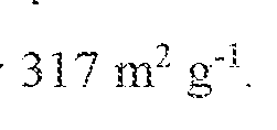
4. The silicon-carbon composite material of claim I, wherein a specific volume of the number of hollow shell carbon particies is approximately

5. A battery, comprising:
a first electrode, including:
a number of hollow shell carbon particles; and
a plurality of silicon nanoparticles within each of the hollow shell carbon particles and occupying less than a total volume within the each hollow shell carbon particle;
wherein at least a portion of the plurality of silicon nanoparticles are located along an inside wall of each hollow shell carbon particle;
a second electrode; and
an electrolyte in contact with both the first electrode and the second electrode.
6. The battery of claim 5, wherein the plurality of silicon nanoparticles are uniformly distributed along the inside wall of each hollow shell carbon particle.
7. The battery of claim 5, wherein the first electrode includes approximately 46 wt% hollow shell carbon particles.
8. The battery of claim 7, wherein the first electrode further includes approximately 46 wt.% graphite.
9. The battery of claim 8, wherein the first electrode further includes approximately 5 wt% carbon black.
10. The batter}' of claim 9, wherein the first electrode further includes approximately 3 wt% carboxymethyl cellulose binder.
1 1 . A method of forming a battery electrode, comprising:
forming a hydrogen terminated surface on a plurality of silicon
nanoparticles;
tethering a plurality of hydrocarbon chains onto the hydrogen terminated surface to form coated silicon nanoparticles,
dissolving the coated silicon nanoparticles in a solvent;
mixing the solvent and silicon nanoparticles with an aqueous medium and emulsifying to form silicon nanopartiele droplets;
carbonizing the silicon nanopartiele droplets to form a plurality of silicon- carbon composite particles having:
a number of hollow shell carbon particles;
a plurality of silicon nanoparticles withm each of the hollow shell carbon particles and occupying less than a total volume within the each hollow shell carbon particle;
wherein at least a portion of the plurality of silicon nanoparticles are located along an inside wall of each hollow shell carbon particle.
12. The method of claim 11, further including coating the silicon nanoparticle droplets with resorcinoi -formaldehyde prior to carbonization.
13. The method of claim 11, wherein dissolving the coated silicon nanoparticles in the solvent includes dissolving the coated silicon nanoparticles in stryrene.
14. The method of claim 1 1 , wherein dissolving the coated silicon nanoparticles in the solvent includes dissolving the coated silicon nanoparticles in hexadecane.
15. The method of claim 1 1 , wherein carbonizing the silicon nanoparticle droplets includes carbonizing to form a plurality of silicon nanoparticles uniformly distributed along the inside wall of each hollow shell carbon particle.
Applications Claiming Priority (2)
| Application Number | Priority Date | Filing Date | Title |
|---|---|---|---|
| US201762517161P | 2017-06-09 | 2017-06-09 | |
| US62/517,161 | 2017-06-09 |
Publications (1)
| Publication Number | Publication Date |
|---|---|
| WO2018227155A1 true WO2018227155A1 (en) | 2018-12-13 |
Family
ID=64566394
Family Applications (1)
| Application Number | Title | Priority Date | Filing Date |
|---|---|---|---|
| PCT/US2018/036756 Ceased WO2018227155A1 (en) | 2017-06-09 | 2018-06-08 | Silicon carbon composite electrode and method |
Country Status (1)
| Country | Link |
|---|---|
| WO (1) | WO2018227155A1 (en) |
Citations (5)
| Publication number | Priority date | Publication date | Assignee | Title |
|---|---|---|---|---|
| US20130344391A1 (en) * | 2012-06-18 | 2013-12-26 | Sila Nanotechnologies Inc. | Multi-shell structures and fabrication methods for battery active materials with expansion properties |
| US20130344392A1 (en) * | 2011-06-30 | 2013-12-26 | Northwestern University | Crumpled graphene-encapsulated nanostructures and lithium ion battery anodes made therefrom |
| US20140287315A1 (en) * | 2013-03-19 | 2014-09-25 | Wacker Chemie Ag | Si/C COMPOSITES AS ANODE MATERIALS FOR LITHIUM ION BATTERIES |
| US20150162617A1 (en) * | 2013-12-09 | 2015-06-11 | Nano And Advanced Materials Institute Limited | Si@C core/shell Nanomaterials for High Performance Anode of Lithium Ion Batteries |
| US20170012282A1 (en) * | 2014-01-31 | 2017-01-12 | Kabushiki Kaisha Toyota Jidoshokki | Negative electrode for nonaqueous secondary battery and nonaqueous secondary battery, negative electrode active material and method for producing same, complex including nano silicon, carbon layer, and cationic polymer layer, and method for producing complex formed of nano silicon and carbon layer |
-
2018
- 2018-06-08 WO PCT/US2018/036756 patent/WO2018227155A1/en not_active Ceased
Patent Citations (5)
| Publication number | Priority date | Publication date | Assignee | Title |
|---|---|---|---|---|
| US20130344392A1 (en) * | 2011-06-30 | 2013-12-26 | Northwestern University | Crumpled graphene-encapsulated nanostructures and lithium ion battery anodes made therefrom |
| US20130344391A1 (en) * | 2012-06-18 | 2013-12-26 | Sila Nanotechnologies Inc. | Multi-shell structures and fabrication methods for battery active materials with expansion properties |
| US20140287315A1 (en) * | 2013-03-19 | 2014-09-25 | Wacker Chemie Ag | Si/C COMPOSITES AS ANODE MATERIALS FOR LITHIUM ION BATTERIES |
| US20150162617A1 (en) * | 2013-12-09 | 2015-06-11 | Nano And Advanced Materials Institute Limited | Si@C core/shell Nanomaterials for High Performance Anode of Lithium Ion Batteries |
| US20170012282A1 (en) * | 2014-01-31 | 2017-01-12 | Kabushiki Kaisha Toyota Jidoshokki | Negative electrode for nonaqueous secondary battery and nonaqueous secondary battery, negative electrode active material and method for producing same, complex including nano silicon, carbon layer, and cationic polymer layer, and method for producing complex formed of nano silicon and carbon layer |
Non-Patent Citations (1)
| Title |
|---|
| "Density of the Elements", PERIODICTABLE.COM, 1 June 2017 (2017-06-01), Retrieved from the Internet <URL:http://periodictable.com/Properties/A/Density.al.html> [retrieved on 20180814] * |
Similar Documents
| Publication | Publication Date | Title |
|---|---|---|
| JP7505783B2 (en) | Silicon-carbon composite anode material | |
| Sun et al. | Super-aligned carbon nanotube/graphene hybrid materials as a framework for sulfur cathodes in high performance lithium sulfur batteries | |
| Liu et al. | 3D pomegranate-like structures of porous carbon microspheres self-assembled by hollow thin-walled highly-graphitized nanoballs as sulfur immobilizers for Li–S batteries | |
| Jin et al. | Thermal pyrolysis of Si@ ZIF-67 into Si@ N-doped CNTs towards highly stable lithium storage | |
| CN111525121B (en) | Silicon anode material with villus structure and preparation method thereof | |
| Jiang et al. | An easy way for preparing high performance porous silicon powder by acid etching Al–Si alloy powder for lithium ion battery | |
| CN107925124B (en) | Silicon-carbon composite particle material | |
| Liu et al. | Facile synthesis of MnO multi-core@ nitrogen-doped carbon shell nanoparticles for high performance lithium-ion battery anodes | |
| Shao et al. | Nanostructured silicon/porous carbon spherical composite as a high capacity anode for Li-ion batteries | |
| Kim et al. | Meso-porous silicon-coated carbon nanotube as an anode for lithium-ion battery | |
| Wang et al. | Hierarchical SnO2/carbon nanofibrous composite derived from cellulose substance as anode material for lithium‐ion batteries | |
| Sun et al. | Amorphous red phosphorus anchored on carbon nanotubes as high performance electrodes for lithium ion batteries | |
| Kong et al. | Binder-free polymer encapsulated sulfur–carbon nanotube composite cathodes for high performance lithium batteries | |
| Wang et al. | Onion-like carbon matrix supported Co 3 O 4 nanocomposites: a highly reversible anode material for lithium ion batteries with excellent cycling stability | |
| Xu et al. | A maize-like FePO 4@ MCNT nanowire composite for sodium-ion batteries via a microemulsion technique | |
| Kim et al. | Freestanding sulfur-graphene oxide/carbon composite paper as a stable cathode for high performance lithium-sulfur batteries | |
| JP6583404B2 (en) | Anode material for lithium ion battery, negative electrode including the anode material, and lithium ion battery | |
| Huang et al. | Bio-templated fabrication of MnO nanoparticles in SiOC matrix with lithium storage properties | |
| WO2016106487A1 (en) | Silicon-carbon composite, a method for preparing said composite, and an electrode material and a battery comprising said composite | |
| Fang et al. | Si nanoparticles encapsulated in elastic hollow carbon fibres for Li-ion battery anodes with high structural stability | |
| JP2019513673A (en) | Carbon-sulfur complex, method for producing the same, positive electrode including the same and lithium-sulfur battery | |
| Han et al. | Graphene caging silicon nanoparticles anchored on graphene sheets for high performance Li-ion batteries | |
| KR20140082965A (en) | Si/C COMPOSITE MATERIAL, METHOD FOR MANUFACTURING SAME, AND ELECTRODE | |
| CA2888561A1 (en) | Method of producing electrode material for lithium-ion secondary battery and lithium-ion battery using such electrode material | |
| Yao et al. | Zinc ferrite nanorods coated with polydopamine-derived carbon for high-rate lithium ion batteries |
Legal Events
| Date | Code | Title | Description |
|---|---|---|---|
| 121 | Ep: the epo has been informed by wipo that ep was designated in this application |
Ref document number: 18814222 Country of ref document: EP Kind code of ref document: A1 |
|
| NENP | Non-entry into the national phase |
Ref country code: DE |
|
| 122 | Ep: pct application non-entry in european phase |
Ref document number: 18814222 Country of ref document: EP Kind code of ref document: A1 |