WO2018224261A1 - An electric motor rotor-shaft group - Google Patents
An electric motor rotor-shaft group Download PDFInfo
- Publication number
- WO2018224261A1 WO2018224261A1 PCT/EP2018/062726 EP2018062726W WO2018224261A1 WO 2018224261 A1 WO2018224261 A1 WO 2018224261A1 EP 2018062726 W EP2018062726 W EP 2018062726W WO 2018224261 A1 WO2018224261 A1 WO 2018224261A1
- Authority
- WO
- WIPO (PCT)
- Prior art keywords
- shaft
- rotor
- pins
- electric motor
- stator
- Prior art date
- Legal status (The legal status is an assumption and is not a legal conclusion. Google has not performed a legal analysis and makes no representation as to the accuracy of the status listed.)
- Ceased
Links
Images



Classifications
-
- H—ELECTRICITY
- H02—GENERATION; CONVERSION OR DISTRIBUTION OF ELECTRIC POWER
- H02K—DYNAMO-ELECTRIC MACHINES
- H02K7/00—Arrangements for handling mechanical energy structurally associated with dynamo-electric machines, e.g. structural association with mechanical driving motors or auxiliary dynamo-electric machines
- H02K7/003—Couplings; Details of shafts
-
- H—ELECTRICITY
- H02—GENERATION; CONVERSION OR DISTRIBUTION OF ELECTRIC POWER
- H02K—DYNAMO-ELECTRIC MACHINES
- H02K1/00—Details of the magnetic circuit
- H02K1/06—Details of the magnetic circuit characterised by the shape, form or construction
- H02K1/22—Rotating parts of the magnetic circuit
- H02K1/28—Means for mounting or fastening rotating magnetic parts on to, or to, the rotor structures
-
- H—ELECTRICITY
- H02—GENERATION; CONVERSION OR DISTRIBUTION OF ELECTRIC POWER
- H02K—DYNAMO-ELECTRIC MACHINES
- H02K15/00—Processes or apparatus specially adapted for manufacturing, assembling, maintaining or repairing of dynamo-electric machines
- H02K15/02—Processes or apparatus specially adapted for manufacturing, assembling, maintaining or repairing of dynamo-electric machines of stator or rotor bodies
-
- F—MECHANICAL ENGINEERING; LIGHTING; HEATING; WEAPONS; BLASTING
- F04—POSITIVE - DISPLACEMENT MACHINES FOR LIQUIDS; PUMPS FOR LIQUIDS OR ELASTIC FLUIDS
- F04C—ROTARY-PISTON, OR OSCILLATING-PISTON, POSITIVE-DISPLACEMENT MACHINES FOR LIQUIDS; ROTARY-PISTON, OR OSCILLATING-PISTON, POSITIVE-DISPLACEMENT PUMPS
- F04C2240/00—Components
- F04C2240/40—Electric motor
Definitions
- the present invention relates to an electric motor comprising a stator, a rotor and a shaft that enables the rotor to be supported by ball bearings.
- electric motors (1') used in industrial applications comprise a stator (2') that is fixed in an outer casing and a rotor (3') that moves in the stator (2'), and the shaft (4') that is grouped with the rotor (3') is supported from the two ends thereof by ball bearings (5') at the center of the end-shields (6') arranged at the front and back of the stator (2').
- the rotor (3') - shaft (4') group is formed.
- the shaft (4') is snap-fitted into the rotor (3') to form a group, deformations occur especially in the shaft (4') or the rotor (3') due to high compression forces, increasing the amount of scrap.
- the aim of the present invention is the realization of an electric motor wherein the motor shaft can be mounted to the rotor without the need for high compression forces during the production.
- the electric motor is a permanent magnet synchronous motor, and comprises a plurality of magnet coupling holes wherein the magnets are inserted, extending axially from the circular surface of the rotor into the latter.
- the pins penetrating the inner surface of the shaft bore by means of the nailing means reach the magnet coupling holes, thus creating a barrier in front of the magnets and preventing the magnets from dislodging from the magnet coupling holes.
- Figure 1 – is the schematic view of an electric motor in the prior art.
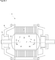
- Figure 2 – is the schematic view of the electric motor of the present invention.
- Figure 3 - is the schematic views of the rotor - shaft group with and without
- Figure 4 - is the schematic views of the rotor - shaft group having magnets with and without
- Figure 5 - is the schematic view of the pin and the conical pin hole.
- Figure 6 - is the schematic view of the rotor - shaft group before the pins are nailed to the rotor.
- Figure 7 - is the schematic view of the rotor - shaft group after the pins are nailed to the rotor.
- Figure 8 - is the cross-sectional view of the rotor - shaft group with the pins nailed to the rotor.
- the electric motor (1) comprises a stator (2) that is fixed in an outer casing; a rotor (3) that moves in the stator (2); a shaft (4) that is inserted through the center of the rotor (3) and that rotates together with the rotor (3); two ball bearings (5) that enable the rotor (3) to be borne so as to move around its own axis and that are attached to the respective ends of the shaft (4), and two end-shields (6) that are mounted to the front and back of the stator (2).
- the electric motor (1) of the present invention comprises two channels (7) that are bored into the shaft (4) at both ends in the direction of the rotation axis; at least two pin holes (9) that extend outwards from the channel (7) in the radial direction towards the outer surface of the shaft (4) and hence up to the inner surface of the shaft bore (8) in the rotor (3), and at least two pins (11) that are inserted into the pin holes (9), that move outwards in the radial direction by means of a nailing means (10) on which a force is exerted in the axial direction at both ends of the shaft (4) into the channels (7) such that the ends of the pins (11) protrude from the outer surface of the shaft (4) and penetrate the inner surface of the shaft bore (8), thus enabling the shaft (4) to be mounted to the rotor (3).
- the rotor (3) - shaft (4) group is formed by means of the pins (11) that are inserted into the shaft (4) and nailed to the shaft bore (8) in the rotor (3).
- the axial channels (7) wherein the nailing means (10) are inserted and the pin holes (9) that extend in the radial direction from the channels (7) to the outer surface of the shaft (4) are formed.
- the number of the pin holes (9) that are bored perpendicularly to the axis of the shaft (4) and the angle therebetween vary based on the desired mechanical strength and dimensions.
- the electric motor (1) comprises the conical pin holes (9) that get larger from the axis of the shaft (4) towards the outer diameter thereof so as to prevent the pin (11) from falling into the channel (7) before being nailed to the rotor (3), further comprising the conical pins (11) that are inserted into the pin holes (9).
- the outer side ends of the pins (11) that are moved outwards in the radial direction by means of the nailing means (10) and that penetrate the inner surface of the shaft bore (8) in the rotor (3) are sharp, and the ends of the pins (11) that extend into the channel (7) are cambered, preferably in a hemispherical form.
- the cambered inner ends of the pins (11) that contact the nailing means (10) enable the pins (11) to be moved in the radial direction by the nailing means (10) that is moved in the axial direction.
- the nailing means (10) pushes the pins (11) out of the pin holes (9) in the radial direction perpendicular to the axis of the shaft (4).
- the sharp ends of the pins (11) protrude from the outer surface of the shaft (4) and penetrate the inner surface of the shaft hole (8) so as to enable the pins (11) to be nailed to the rotor (3).
- the electric motor (1) is a permanent magnet (12) synchronous motor, comprising a plurality of magnet coupling holes (13) that are arranged in the rotor (3) around the shaft (4), that extend from the circular surface of the rotor (3) thereinto in the axial direction and wherein the magnets (12) that provide the synchronous operation are placed, and the pins (11) that penetrate the inner surface of the shaft hole (8) by means of the nailing means (10) reach the magnet coupling holes (13) so as to create a barrier in front of the magnets (12), and thus prevent the magnets (12) from dislodging from the magnet coupling holes (13).
- the electric motor (1) comprises eight pin holes (9) in total, four on each end of the shaft (4), and eight pins (11).
- the four pins (11) are arranged symmetrically in the shaft (4) so that there is an angle of 90° therebetween.
- the need for the pressing process in order to form the rotor (3) - shaft (4) group is eliminated and the shaft (4) is mounted to the rotor (3) in an easy and safe manner.
- the deformations that may occur in the shaft (4) and/or the rotor (3) are prevented.
- the pins (11) prevent the magnets (12) from dislodging.
Landscapes
- Engineering & Computer Science (AREA)
- Power Engineering (AREA)
- Manufacturing & Machinery (AREA)
- Iron Core Of Rotating Electric Machines (AREA)
Abstract
The present invention relates to an electric motor (1) comprising a stator (2) that is fixed in an outer casing; a rotor (3) that moves in the stator (2); a shaft (4) that is inserted through the center of the rotor (3) and that rotates together with the rotor (3); two ball bearings (5) that enable the rotor (3) to be borne so as to move around its own axis and that are attached to the respective ends of the shaft (4); two end-shields (6) that are mounted to the front and back of the stator (2); pin holes (9) that are formed in the shaft (4), and pins (11) that enable the shaft (4) to be mounted to the rotor (3).
Description
The present invention relates to an electric motor comprising a stator, a rotor and a shaft that enables the rotor to be supported by ball bearings.In the state of the art, electric motors (1') used in industrial applications comprise a stator (2') that is fixed in an outer casing and a rotor (3') that moves in the stator (2'), and the shaft (4') that is grouped with the rotor (3') is supported from the two ends thereof by ball bearings (5') at the center of the end-shields (6') arranged at the front and back of the stator (2'). By pressing the shaft (4') snap-fittingly into the shaft bore (8') at the center of the rotor (3'), the rotor (3') - shaft (4') group is formed. In the production of the rotor (3') - shaft (4') group, when the shaft (4') is snap-fitted into the rotor (3') to form a group, deformations occur especially in the shaft (4') or the rotor (3') due to high compression forces, increasing the amount of scrap.
In the United States Patent Application No. US2015280501 (A1), a method and an apparatus for mounting the rotor to the motor shaft in a compressor motor are disclosed.
The aim of the present invention is the realization of an electric motor wherein the motor shaft can be mounted to the rotor without the need for high compression forces during the production.
During the production of the rotor-shaft group of the electric motor realized in order to attain the aim of the present invention, two channels are bored into the shaft in the direction of the rotation axis. Moreover, pin holes are bored, extending outwards from each channel in the radial direction towards the outer surface of the shaft and hence up to the inner surface of the shaft bore in the rotor, and the pins are inserted into the pin holes. By means of a nailing means that exerts force in the axial direction from both ends of the shaft into the channels, the pins move outwards in the radial direction so that the tips thereof protrude from the outer surface of the shaft and enable the shaft to be grouped with the rotor by penetrating the inner surface of the shaft bore.
In an embodiment of the present invention, the electric motor is a permanent magnet synchronous motor, and comprises a plurality of magnet coupling holes wherein the magnets are inserted, extending axially from the circular surface of the rotor into the latter. The pins penetrating the inner surface of the shaft bore by means of the nailing means reach the magnet coupling holes, thus creating a barrier in front of the magnets and preventing the magnets from dislodging from the magnet coupling holes.
The electric motor realized in order to attain the aim of the present invention is illustrated in the attached figures, where:
Figure 1 – is the schematic view of an electric motor in the prior art.
Figure 2 – is the schematic view of the electric motor of the present invention.
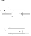
Figure 3 - is the schematic views of the rotor - shaft group with and without
the nailing means.
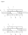
Figure 4 - is the schematic views of the rotor - shaft group having magnets with and without
the nailing means.
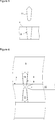
Figure 5 - is the schematic view of the pin and the conical pin hole.
Figure 6 - is the schematic view of the rotor - shaft group before the pins are nailed to the rotor.
Figure 7 - is the schematic view of the rotor - shaft group after the pins are nailed to the rotor.
Figure 8 - is the cross-sectional view of the rotor - shaft group with the pins nailed to the rotor.
The elements in the figures are numbered as follows:
- Electric motor
- Stator
- Rotor
- Shaft
- Ball bearing
- End-shield
- Channel
- Shaft bore
- Pin hole
- Nailing means
- Pin
- Magnet
- Magnet coupling hole
The electric motor (1) comprises a stator (2) that is fixed in an outer casing; a rotor (3) that moves in the stator (2); a shaft (4) that is inserted through the center of the rotor (3) and that rotates together with the rotor (3); two ball bearings (5) that enable the rotor (3) to be borne so as to move around its own axis and that are attached to the respective ends of the shaft (4), and two end-shields (6) that are mounted to the front and back of the stator (2).
The electric motor (1) of the present invention comprises two channels (7) that are bored into the shaft (4) at both ends in the direction of the rotation axis; at least two pin holes (9) that extend outwards from the channel (7) in the radial direction towards the outer surface of the shaft (4) and hence up to the inner surface of the shaft bore (8) in the rotor (3), and at least two pins (11) that are inserted into the pin holes (9), that move outwards in the radial direction by means of a nailing means (10) on which a force is exerted in the axial direction at both ends of the shaft (4) into the channels (7) such that the ends of the pins (11) protrude from the outer surface of the shaft (4) and penetrate the inner surface of the shaft bore (8), thus enabling the shaft (4) to be mounted to the rotor (3).
In the production of the electric motor (1) of the present invention, the rotor (3) - shaft (4) group is formed by means of the pins (11) that are inserted into the shaft (4) and nailed to the shaft bore (8) in the rotor (3). During the production, in the shaft (4), the axial channels (7) wherein the nailing means (10) are inserted and the pin holes (9) that extend in the radial direction from the channels (7) to the outer surface of the shaft (4) are formed. The number of the pin holes (9) that are bored perpendicularly to the axis of the shaft (4) and the angle therebetween vary based on the desired mechanical strength and dimensions.
In an embodiment of the present invention, the electric motor (1) comprises the conical pin holes (9) that get larger from the axis of the shaft (4) towards the outer diameter thereof so as to prevent the pin (11) from falling into the channel (7) before being nailed to the rotor (3), further comprising the conical pins (11) that are inserted into the pin holes (9).
In another embodiment of the present invention, the outer side ends of the pins (11) that are moved outwards in the radial direction by means of the nailing means (10) and that penetrate the inner surface of the shaft bore (8) in the rotor (3) are sharp, and the ends of the pins (11) that extend into the channel (7) are cambered, preferably in a hemispherical form. The cambered inner ends of the pins (11) that contact the nailing means (10) enable the pins (11) to be moved in the radial direction by the nailing means (10) that is moved in the axial direction.
When the pins (11) are inserted into the pin holes (9) before the shaft (4) is nailed to the rotor (3), the cambered hemispherical inner ends of the pins (11) extend into the channel (7). The sharp outer ends of the pins (11) remain in the pin hole (9) - prior to the nailing process - and do not exceed the level of the outer surface of the shaft (4). Thus, the pins (11) do not prevent the shaft (4) from being inserted into the rotor (3). After the shaft (4) is inserted into the shaft bore (8), a force is applied by means of the nailing means (10) that is moved forward in the shaft (4) by being guided by the channels (7) in the axial direction. The nailing means (10) pushes the pins (11) out of the pin holes (9) in the radial direction perpendicular to the axis of the shaft (4). The sharp ends of the pins (11) protrude from the outer surface of the shaft (4) and penetrate the inner surface of the shaft hole (8) so as to enable the pins (11) to be nailed to the rotor (3).
In another embodiment of the present invention, the electric motor (1) is a permanent magnet (12) synchronous motor, comprising a plurality of magnet coupling holes (13) that are arranged in the rotor (3) around the shaft (4), that extend from the circular surface of the rotor (3) thereinto in the axial direction and wherein the magnets (12) that provide the synchronous operation are placed, and the pins (11) that penetrate the inner surface of the shaft hole (8) by means of the nailing means (10) reach the magnet coupling holes (13) so as to create a barrier in front of the magnets (12), and thus prevent the magnets (12) from dislodging from the magnet coupling holes (13).
In an embodiment of the present invention, the electric motor (1) comprises eight pin holes (9) in total, four on each end of the shaft (4), and eight pins (11). In another embodiment of the present invention, the four pins (11) are arranged symmetrically in the shaft (4) so that there is an angle of 90° therebetween.
In the production of the electric motor (1) of the present invention, the need for the pressing process in order to form the rotor (3) - shaft (4) group is eliminated and the shaft (4) is mounted to the rotor (3) in an easy and safe manner. The deformations that may occur in the shaft (4) and/or the rotor (3) are prevented. In the permanent magnet (12) electric motor (1), the pins (11) prevent the magnets (12) from dislodging.
Claims (4)
- An electric motor (1) comprising a stator (2) that is fixed in an outer casing; a rotor (3) that moves in the stator (2); a shaft (4) that is inserted through the center of the rotor (3) and that rotates together with the rotor (3); two ball bearings (5) that enable the rotor (3) to be borne so as to move around its own axis and that are attached to the respective ends of the shaft (4), and two end-shields (6) that are mounted to the front and back of the stator (2), characterized by- two channels (7) that are bored into the shaft (4) at both ends in the direction of the rotation axis,- at least two pin holes (9) that extend outwards from the channel (7) in the radial direction towards the outer surface of the shaft (4) and hence up to the inner surface of the shaft bore (8) in the rotor (3), and- at least two pins (11) that are inserted into the pin holes (9), that move outwards in the radial direction by means of a nailing means (10) on which a force is exerted in the axial direction at both ends of the shaft (4) into the channels (7) such that the ends of the pins (11) protrude from the outer surface of the shaft (4) and penetrate the inner surface of the shaft bore (8), thus enabling the shaft (4) to be mounted to the rotor (3).
- An electric motor (1) as in Claim 1, characterized by the conical pin holes (9) that get larger from the axis of the shaft (4) towards the outer diameter thereof and the conical pins (11) that are inserted into the pin holes (9).
- An electric motor (1) as in Claim 1 or 2, characterized by the pins (11) with the outer side ends thereof that penetrate the inner surface of the shaft (8) being sharp and the inner side ends thereof being cambered.
- An electric motor (1) as in Claim 1 or 2, comprising a plurality of magnet coupling holes (13) wherein magnets (12) are inserted, characterized by the pins (11) that penetrate the inner surface of the shaft bore (8) by means of the nailing means (10) and reach the magnet coupling holes (13) so as to form a barrier in front of the magnets (12).
Applications Claiming Priority (2)
| Application Number | Priority Date | Filing Date | Title |
|---|---|---|---|
| TR201708248 | 2017-06-05 | ||
| TRA2017/08248 | 2017-06-05 |
Publications (1)
| Publication Number | Publication Date |
|---|---|
| WO2018224261A1 true WO2018224261A1 (en) | 2018-12-13 |
Family
ID=62196570
Family Applications (1)
| Application Number | Title | Priority Date | Filing Date |
|---|---|---|---|
| PCT/EP2018/062726 Ceased WO2018224261A1 (en) | 2017-06-05 | 2018-05-16 | An electric motor rotor-shaft group |
Country Status (1)
| Country | Link |
|---|---|
| WO (1) | WO2018224261A1 (en) |
Cited By (2)
| Publication number | Priority date | Publication date | Assignee | Title |
|---|---|---|---|---|
| EP3683933A1 (en) * | 2019-01-18 | 2020-07-22 | Siemens Aktiengesellschaft | Joining of a stack of metal sheets on a shaft |
| US20220231570A1 (en) * | 2019-05-28 | 2022-07-21 | Lg Innotek Co., Ltd. | Motor |
Citations (5)
| Publication number | Priority date | Publication date | Assignee | Title |
|---|---|---|---|---|
| US4164722A (en) * | 1978-01-09 | 1979-08-14 | Woodward Governor Company | Electromagnetic actuator with torque-compensating poles |
| EP0124335A2 (en) * | 1983-04-28 | 1984-11-07 | Pneumo Abex Corporation | Force motor with null centering and null position bias |
| US4629952A (en) * | 1984-08-16 | 1986-12-16 | Honda Giken Kogyo Kabushiki Kaisha | Driving control method and circuit for electromagnetic servo devices |
| US20120019095A1 (en) * | 2010-07-22 | 2012-01-26 | Remy Technologies, L.L.C. | Radial pin coupled hub and rim assembly |
| US20150280501A1 (en) | 2014-03-25 | 2015-10-01 | Trane International Inc. | Methods and systems to mount a rotor to a shaft |
-
2018
- 2018-05-16 WO PCT/EP2018/062726 patent/WO2018224261A1/en not_active Ceased
Patent Citations (5)
| Publication number | Priority date | Publication date | Assignee | Title |
|---|---|---|---|---|
| US4164722A (en) * | 1978-01-09 | 1979-08-14 | Woodward Governor Company | Electromagnetic actuator with torque-compensating poles |
| EP0124335A2 (en) * | 1983-04-28 | 1984-11-07 | Pneumo Abex Corporation | Force motor with null centering and null position bias |
| US4629952A (en) * | 1984-08-16 | 1986-12-16 | Honda Giken Kogyo Kabushiki Kaisha | Driving control method and circuit for electromagnetic servo devices |
| US20120019095A1 (en) * | 2010-07-22 | 2012-01-26 | Remy Technologies, L.L.C. | Radial pin coupled hub and rim assembly |
| US20150280501A1 (en) | 2014-03-25 | 2015-10-01 | Trane International Inc. | Methods and systems to mount a rotor to a shaft |
Cited By (5)
| Publication number | Priority date | Publication date | Assignee | Title |
|---|---|---|---|---|
| EP3683933A1 (en) * | 2019-01-18 | 2020-07-22 | Siemens Aktiengesellschaft | Joining of a stack of metal sheets on a shaft |
| WO2020148048A1 (en) * | 2019-01-18 | 2020-07-23 | Siemens Aktiengesellschaft | Joining a laminated core to a shaft |
| US12255496B2 (en) | 2019-01-18 | 2025-03-18 | Siemens Aktiengesellschaft | Joining a laminated core to a shaft |
| US20220231570A1 (en) * | 2019-05-28 | 2022-07-21 | Lg Innotek Co., Ltd. | Motor |
| US12249894B2 (en) * | 2019-05-28 | 2025-03-11 | Lg Innotek Co., Ltd. | Motor |
Similar Documents
| Publication | Publication Date | Title |
|---|---|---|
| US10177616B2 (en) | Spoke permanent magnet rotor | |
| EP2854258A1 (en) | Permanent magnet rotor shaft assembly and method | |
| US10978924B2 (en) | Rotor of electrical rotating machine | |
| EP2860848B1 (en) | Rotary electric machine | |
| US9369014B2 (en) | Rotor of motor and fan driving motor including rotor | |
| US20110241473A1 (en) | Electric Motor Rotor | |
| CN201533204U (en) | Magnetic steel fixing structure of motor rotor | |
| JP2018033265A (en) | Rotor structure of rotating electrical machine | |
| US20110248592A1 (en) | Synchronous Machine | |
| WO2018224261A1 (en) | An electric motor rotor-shaft group | |
| KR20110128176A (en) | Magnetic ring of multi pole generator for wind turbine | |
| US20130313933A1 (en) | Rotor of motor and fan driving motor including rotor | |
| CN104412491A (en) | Stator arrangement for an electrical machine | |
| KR102067406B1 (en) | Rotor of rotary electric machine | |
| KR101657938B1 (en) | Method for producing a rotor | |
| KR101603206B1 (en) | rotor of BLDC motor, pressing jig for manufacturing rotor and manufacturing method of rotor using the same | |
| EP2044672A1 (en) | An electric motor | |
| EP3355443A1 (en) | Outer rotor type motor | |
| US11114907B2 (en) | Motor rotor assembly and method of aligning pole center of permanent magnet thereof | |
| EP1796244A3 (en) | Rotating electrical machine for alternator and method of manufacturing rotor core used in the same | |
| KR101683638B1 (en) | motor and method of manufacturing stator core thereof | |
| CN210957949U (en) | Inner rotor magnetic sheet structure | |
| JP5928327B2 (en) | Electromagnetic clutch and manufacturing method thereof | |
| KR100751588B1 (en) | Permanent Magnet Embedded High Speed Motor | |
| WO2016174450A1 (en) | Rotor |
Legal Events
| Date | Code | Title | Description |
|---|---|---|---|
| 121 | Ep: the epo has been informed by wipo that ep was designated in this application |
Ref document number: 18725483 Country of ref document: EP Kind code of ref document: A1 |
|
| NENP | Non-entry into the national phase |
Ref country code: DE |
|
| 122 | Ep: pct application non-entry in european phase |
Ref document number: 18725483 Country of ref document: EP Kind code of ref document: A1 |