WO2018221085A1 - 採水ディスペンサー - Google Patents
採水ディスペンサー Download PDFInfo
- Publication number
- WO2018221085A1 WO2018221085A1 PCT/JP2018/016628 JP2018016628W WO2018221085A1 WO 2018221085 A1 WO2018221085 A1 WO 2018221085A1 JP 2018016628 W JP2018016628 W JP 2018016628W WO 2018221085 A1 WO2018221085 A1 WO 2018221085A1
- Authority
- WO
- WIPO (PCT)
- Prior art keywords
- water
- pure water
- main body
- hinge
- dispenser
- Prior art date
- Legal status (The legal status is an assumption and is not a legal conclusion. Google has not performed a legal analysis and makes no representation as to the accuracy of the status listed.)
- Ceased
Links
Images

Classifications
-
- B—PERFORMING OPERATIONS; TRANSPORTING
- B01—PHYSICAL OR CHEMICAL PROCESSES OR APPARATUS IN GENERAL
- B01J—CHEMICAL OR PHYSICAL PROCESSES, e.g. CATALYSIS OR COLLOID CHEMISTRY; THEIR RELEVANT APPARATUS
- B01J4/00—Feed or outlet devices; Feed or outlet control devices
Definitions
- the present invention relates to a water dispensing dispenser that is connected to a pure water production apparatus or the like and discharges pure water according to demand.
- a water collection dispenser connected to a pure water production apparatus is widely used.
- the water sampling dispenser includes a nozzle that discharges pure water, and an open / close valve that is provided in a path of pure water to the nozzle and supplies pure water to the nozzle and shuts off the supply.
- the water sampling dispenser is usually provided at a location away from the main body of the pure water production apparatus, and is connected to the pure water outlet of the pure water production apparatus main body by piping.
- the on-off valve When the user operates the on-off valve, pure water is discharged from the nozzle, and thus the user can collect pure water in an amount according to the necessity.
- a manual valve can be used, but an electromagnetic valve can also be used.
- the manual on-off valve is not limited to one operated by hand, but includes one operated by a foot pedal or the like, for example.
- the solenoid valve When using a solenoid valve, the solenoid valve is controlled by a push button switch that can be operated by a finger or a foot switch that can be operated by a foot, and pure water is discharged from the nozzle. Furthermore, by combining the flow sensor and the solenoid valve, the specified amount of pure water can be removed by opening the solenoid valve until the flow rate measured by the flow sensor reaches the specified value when there is a single switch operation. It is also possible to collect water.
- Patent Document 1 discloses an example of the configuration of a water sampling dispenser.
- the water sampling dispenser of Patent Document 1 is of a stand type including a base (base) part placed on an experimental table, a column extending vertically upward from the base unit, and a head unit attached to the column.
- the pure water is discharged from the nozzle provided in the head part.
- the base unit is connected to a pure water production apparatus via a pipe and includes a button switch used for setting a water sampling amount and a display unit for displaying a water sampling amount. Since the main body of the deionized water production device is installed at a location away from the point of use where the user is located, information such as the water quality and the operation status of the deionized water production device can be displayed on the display unit of the water sampling dispenser. There are many cases.
- the base portion and the head portion are connected by a flexible pipe, and the head portion is configured to be removable from the column as necessary.
- the water dispenser is placed on a test stand, which is a use point, for example, and is operated by the user. At this time, there are a case where the user operates the water sampling dispenser while standing and a case where the user operates while sitting on a chair. Since the position and angle of the user's line of sight are different between standing and sitting, it may be difficult to see characters or figures displayed on the display portion of the water dispensing dispenser.
- the display unit is configured with a touch panel to accept input from the user, the operability during the input operation differs depending on whether the user is standing or sitting.
- An object of the present invention is to provide a water dispensing dispenser in which a user can easily see the display on the display unit regardless of whether the user is standing or sitting.
- the water sampling dispenser of the present invention is a water sampling dispenser used for pure water sampling, and has a main body part to which pure water is supplied from a pure water production apparatus and a nozzle for discharging pure water.
- the display unit is provided with a head unit connected by piping to the main body unit, and the display unit has a function of holding an opening angle so that an angle between the display surface and a horizontal plane can be adjusted. It is attached with respect to the housing of a main-body part with the hinge which has.
- the hinge is a member that can relatively rotate two objects around the rotation axis.
- an angle formed by two objects around the rotation axis is referred to as an opening angle.
- the display unit is attached to the housing of the main body using a hinge having a function of maintaining the opening angle, so that the user can set the angle of the display with respect to the main body as desired.
- the angle setting can be changed as necessary.
- the hinge having a function of maintaining the opening angle include a torque hinge and a variable stop hinge.
- a water dispensing dispenser capable of providing a display that is easy for the user to see regardless of whether the user is standing or sitting.
- FIG. 1 is a flow sheet showing a state in which a water dispensing dispenser according to an embodiment of the present invention is combined with a pure water production apparatus.
- the pure water production apparatus can be broadly divided into a primary pure water production apparatus 30 that supplies tap water and generates primary pure water, and a primary pure water produced by the primary pure water production apparatus 30 via a pipe 45. It consists of a subsystem 50 that is supplied and produces pure water with higher purity, that is, a secondary pure water system.
- the subsystem 50 includes a circulation purification system.
- supply water such as tap water is introduced into an activated carbon cartridge (CC) 32 through a valve 31.
- the outlet water of the activated carbon cartridge 32 is sent to a reverse osmosis device (RO) 35 having a reverse osmosis membrane via a pressure switch (PS) 33 and a pump 34.
- RO reverse osmosis device
- a pipe 43 having an orifice 36 is connected to the concentration side of the reverse osmosis device 35, and waste water from the concentration side is discharged through the pipe 43.
- the orifice 36 is provided to keep the pressure on the concentration side of the reverse osmosis device 35 constant.
- the water that has passed through the reverse osmosis membrane of the reverse osmosis device 35 is then sequentially passed to non-regenerative ion exchange devices (CP: also called cartridge polishers) 39 and 41 arranged in two stages in series.
- the non-regenerative ion exchangers 39 and 41 are each filled with a strongly acidic cation exchange resin and a strongly basic anion exchange resin in a mixed bed.
- a conductivity meter (CI) for measuring the conductivity and temperature of water sent to the non-regenerative ion exchange device 39, respectively. 37 and a thermometer (TI) 38 are connected.
- a conductivity meter 40 is also provided in the piping between the first and second non-regenerative ion exchange devices 39 and 41.
- a check valve 42 is provided at the outlet of the non-regenerative ion exchange device 41. The outlet of the check valve 42 is an outlet of the primary pure water production apparatus 30 and is connected with a pipe 45.
- the activated carbon cartridge 32, the reverse osmosis device 35, and the non-regenerative ion exchange devices 39 and 41 are all cartridge types that can be easily exchanged.
- the subsystem 50 includes a storage tank 51 to which primary pure water is supplied from a pipe 45 through a valve 52.
- the storage tank 51 includes an ultraviolet irradiation device 53 for sterilizing the pure water in the storage tank 51 by irradiating ultraviolet light, a level sensor (LS) 54 for detecting the level of pure water in the storage tank 51, and a vent filter 55. And are provided.
- the storage tank 51 communicates with the atmosphere via the vent filter 55, and the pressure in the storage tank 51 is maintained at atmospheric pressure.
- the ultraviolet irradiation device 53 for example, a device using an ultraviolet LED, a device using an ultraviolet lamp, or the like can be used.
- a pump 56 for feeding pure water in the storage tank 51 is provided at the outlet of the storage tank 51, and an ultraviolet oxidation device (UV) 57, a non-regenerative type provided in two stages in series, is provided at the outlet of the pump 56.
- Ion exchange devices 58 and 59 and an ultrafiltration device (UF) 60 are provided in this order.
- a pipe 101 branched from the outlet pipe of the pump 56 is provided, and an outlet port 71 is provided at the tip of the pipe 101.
- the ultrafiltration device 60 is provided with a pipe 106 for draining water on the primary side of the ultrafiltration membrane, and the pipe 106 is provided with a valve 107.
- a pipe 102 connected to an outlet port 72 is connected to the outlet of the ultrafiltration device 60, and a resistance meter (RI) for measuring the electrical resistivity and temperature of pure water flowing therethrough is connected to the pipe 102, respectively. 63 and a thermometer 64 are connected.
- a pipe 103 for returning pure water to the storage tank 51 side is also provided at the outlet of the ultrafiltration device 60, and a constant flow valve 61 is attached to the tip of the pipe 103.
- a TOC meter (TOCI) 62 for measuring the total organic carbon (TOC) concentration of pure water flowing therethrough.
- a pipe 104 returning to the storage tank 51 and a pipe 105 connected to the outlet port 73 are connected to the outlet of the constant flow valve 61.
- a back pressure valve 65 is provided in the pipe 105.
- a sampling valve 66 used for sampling pure water is attached to the pipe 104.
- a circulation purification system is formed that returns from the storage tank 51 to the storage tank 51 through the pump 56, the ultraviolet oxidation device 57, the non-regenerative ion exchange devices 58 and 59, the ultrafiltration device 60, and the constant flow valve 61.
- the primary pure water is further purified while circulating through this circulation purification system, thereby obtaining pure water to be supplied to the use point.
- the ultraviolet oxidizer 57 is for decomposing all organic carbon in pure water and has a sterilizing action.
- the operation of the circulation purification system may be stopped at night or on holidays, and during the stop period.
- the ultraviolet irradiation apparatus 53 in the storage tank 51 separately from the ultraviolet oxidation apparatus 57. Since it is necessary to be able to dissociate water, a low-pressure mercury lamp is generally used as the ultraviolet light source in the ultraviolet oxidation device 57.
- a valve 68 is connected to the pipe 45 in order to discharge the primary pure water from the pipe 45 as waste water as it is.
- a valve 69 for draining the inside of the storage tank 51 is also provided at the outlet of the storage tank 51.
- a check valve 67 is provided between the drain side of the valve 69 and the inlet side of the storage tank 51.
- a main controller 70 is provided to control the overall operation of the pure water production apparatus.
- the main controller 70 may be connected to a sensor that detects water leakage in the pure water production apparatus.
- the main controller 70 includes sensors provided in the pure water production apparatus, such as a pressure switch 33, conductivity meters 37 and 40, thermometers 38 and 64, a level sensor 54, a resistivity meter 63, and a TOC meter 62.
- the detection output is input to control the drive of the pumps 34 and 56 and the valves 31, 52, 68 and 107.
- the exit ports 71 to 73 provided in the subsystem 50 are ports that are connection positions of the water sampling dispenser 10.
- the water sampling dispenser 10 is connected to any one of the outlet ports 71 to 73 by, for example, a flexible pipe 75.
- three outlet ports 71 to 73 are provided, but the connection points of the outlet ports to the circulation purification system are not limited to those shown in FIG.
- the number of outlet ports connected to the circulation purification system is not limited to 3, but can be increased or decreased.
- a plurality of outlet ports connected to the outlet of the ultrafiltration device 60 may be provided, and the water sampling dispenser 10 may be connected to each outlet port.
- the circulation purification system of the subsystem 50 is provided with an ultraviolet irradiation device 53 and an ultraviolet oxidation device 57, and sterilization is performed on the pure water circulating in the circulation purification system, but a pipe branched from the circulation purification system
- the water collection dispenser 10 described here is provided with an ultraviolet sterilization mechanism using an ultraviolet LED in itself, and can always supply pure water with a reduced number of viable bacteria contained therein.
- FIG. 2 shows the appearance of the water sampling dispenser 10.
- FIG. 2 does not show the piping 75 and various wirings used for connection with the pure water production apparatus.
- the water dispensing dispenser 10 is roughly divided into a head portion 10a, a main body portion 10b, and a support column 10c that extends vertically upward from the main body portion 10b and removably holds the head 10a.
- the head portion 10a The main body 10b is connected by a flexible pipe 14.
- As a usage pattern of the water sampling dispenser 10 for example, it is used to pour pure water into a large number of test tubes arranged in line on a laboratory bench.
- a head unit 10a that can be gripped by a user and moved to a desired position is provided, and a nozzle 16 that actually serves as a spout for pure water is provided in the head unit 10a.
- the head portion 10a is provided with a handle 28 or a handle for the user to hold.
- the holding position of the head 10a on the column 10c can be changed,
- the support column 10c needs to have a sufficient length.
- the head portion 10a discharges pure water sent from the main body portion 10b through the pipe 14 from the nozzle 16, and, as shown in FIG. 15 and an ultraviolet irradiation unit 17 that irradiates the pure water flowing through the flow path 15 with ultraviolet rays.
- the nozzle 16 is provided at the end of the flow path 15.
- the ultraviolet irradiation unit 17 functions as an ultraviolet sterilization mechanism, and an ultraviolet LED is used as the ultraviolet source in the ultraviolet irradiation unit 17.
- the head unit 10a includes a switch 18 operated by the user in order to discharge pure water according to the user's demand. As shown in FIG. 2, the head 10a is provided with a button 26 at a position where a user who holds the handle 25 can easily operate with the finger.
- the button 26 is mechanically connected to the switch 18, and the switch 18 is operated by operating the button 26.
- the main body 10b includes a pipe 11 having one end connected to the pipe 75 from the subunit 50, a flow sensor (FI) 12 provided in the pipe 11, and an electromagnetic valve 13 attached to the other end of the pipe 11.
- a control unit 20 for controlling the operation of the water sampling dispenser 10 and an operation panel 19 connected to the control unit 20 are provided.
- the electromagnetic valve 13 is opened by a drive signal from the control unit 20.
- the operation panel 19 accepts, for example, settings for the amount of water collected and the water sampling mode from the user, and displays necessary information for the user. Examples of the water sampling mode include a quantitative mode and an arbitrary amount mode.
- the control unit 20 performs overall control of the water sampling dispenser 10, for example, when receiving a water sampling request input from the user via the switch 18 of the head unit 10a, and the water sampling mode is the quantitative mode.
- the solenoid valve 13 is opened until the accumulated value of the flow rate detected by the flow rate sensor 12 reaches the set value, so that the amount of pure water indicated by the set value is supplied to the head unit 10a.
- the control unit 20 performs control to open the electromagnetic valve 13 only during a period in which the switch 18 is operated.
- the control unit 20 performs control so that the ultraviolet LED in the ultraviolet irradiation unit 17 is driven only when the electromagnetic valve 13 is open regardless of the water sampling mode.
- control unit 20 is connected to the main controller 70 of the pure water production apparatus by wiring not shown, and is measured from the main control apparatus 70 with respect to the operating state of the pure water production apparatus, in particular, with the TOC meter 62.
- the water quality data such as the TOC value, the resistivity measured by the resistivity meter 63, and the temperature value measured by the thermometer 64 are received.
- the control unit 20 displays the received water quality data on the operation panel 19 in a predetermined format.
- the operation panel 19 has a flat shape, and is attached to the housing 21 through a torque hinge 23 at one end thereof.
- a touch panel 22 in which a liquid crystal display panel and a touch sensor are integrated is provided on one surface of the operation panel 19.
- the touch panel 22 functions as a display unit that performs display for the user, and receives input from the user when the user touches a predetermined position on the touch panel 22.
- the rotation axis of the torque hinge 23 is parallel to the surface of the casing 21 at the position of the torque hinge 23.
- the operation panel 19 can be rotated within such an angle range, and an angle formed between the display surface, that is, the surface of the touch panel 22 and the horizontal plane can be adjusted.
- the torque hinge 23 used in the present embodiment is a kind of hinge having a function of maintaining an opening angle, and is also called a free stop hinge.
- torque greater than a threshold value is applied. It is necessary to apply.
- the torque hinge 3 does not move and maintains its state, that is, the posture.
- the threshold value when the user moves the operation panel 19 with the intention of adjusting the angle of the operation panel 19, the torque hinge 23 easily rotates, and the user presses the surface of the touch panel 22 for input.
- a torque hinge 23 that does not rotate with a certain force is used.
- a threshold value of 1.08 N ⁇ m is used.
- the user can adjust the angle of the operation panel 19 with respect to the housing 21 depending on whether water is collected while standing or sitting on a chair. it can. As a result, the user can confirm the display on the operation panel 19, for example, the display of water quality data, etc. at an angle that is most easily viewable according to the work posture.
- the angle of the operation panel 19 that is the display unit with respect to the housing 21 is variable in this way, if a push button for operation is provided on the main body of the housing 21, the finger that presses the push button and the operation panel 19 are arranged.
- the operation panel 19 is configured by the touch panel 22, the operation panel 19 is a target on which an input operation is performed, and the operability is favorably maintained. be able to.
- the torque hinge 23 is used as a hinge having a function of maintaining the opening angle.
- the hinge that can be used for attaching the operation panel 19 to the housing 21 is a torque. It is not limited to hinges, and other types of hinges can be used.
- the water sampling dispenser shown in FIG. 4 is the same as the water sampling dispenser of the above-described embodiment, but the above-described implementation is that the variable stop hinge 27 is used as a hinge having a function of maintaining an opening angle. It is different from the form water sampling dispenser.
- the variable stop hinge 27 is a hinge that can select one of a plurality of opening angles and fix the opening angle, and can reset the opening angle.
- the operation panel is attached to the casing 21 by a movable stop hinge 27 whose opening angle is set in increments of 15 °, for example.
- the angle formed between the operation panel 19 and the casing 21 by the variable stop hinge 27 is fixed to one of a plurality of set opening angles.
- a release button 28 provided at the tip of the rotation axis direction of the variable stop hinge 27, the engaged state inside the hinge is released. In this state, as shown by the arrow in the drawing, The operation panel 19 can be arbitrarily rotated with respect to the casing 21 around the rotation axis.
- the hinge When the push-in of the release button 28 is stopped, the hinge is fixed to the opening angle closest to the actual opening angle at that time among the plurality of opening angles set in the variable step hinge 27. .
- the variable stop hinge 27 When the variable stop hinge 27 is used in this way, the hinge is fixed unless the release button 28 is touched. Therefore, when the touch panel 22 of the operation panel 19 is touched for input, the hinge is loosened and the operation panel 19 moves. This can be reliably prevented, and the operability when using the touch panel 22 is improved.
Landscapes
- Chemical & Material Sciences (AREA)
- Organic Chemistry (AREA)
- Chemical Kinetics & Catalysis (AREA)
- Physical Water Treatments (AREA)
- Sampling And Sample Adjustment (AREA)
Abstract
純水の採水に用いられる採水ディスペンサーは、純水製造装置から純水が供給される本体部と、純水を吐出するノズルを有し本体部に対して配管によって接続されたヘッド部と、本体部に設けられた表示部と、を備える。表示部は、その表示面と水平面となす角度を調節可能であるように、開き角を保持する機能を有するヒンジにより本体部の筺体に対して取り付けられている。
Description
本発明は、純水製造装置などに接続され、需要に応じて純水を吐出する採水ディスペンサーに関する。
研究機関などにおいて純水を利用する場合、比較的小型の純水製造装置を用いて純水を製造することが多い。そしてユースポイントにおいて純水を例えばビーカー、フラスコ、試験管などに採水するために、純水製造装置に接続する採水ディスペンサーが広く用いられている。採水ディスペンサーは、純水を吐出するノズルと、ノズルへの純水の経路に設けられてノズルに対して純水を供給し、またこの供給を遮断する開閉弁とを備えている。採水ディスペンサーは、通常、純水製造装置の本体とは離れた場所に設けられ、配管によって純水製造装置本体の純水出口に接続される。利用者が開閉弁を操作することによってノズルから純水が吐出し、これにより、利用者はその必要に応じた量で純水を採水することができる。開閉弁としては、手動のものを用いることもできるが、電磁弁を用いることもできる。手動の開閉弁としては、手で操作されるものに限定されず、例えば、足踏みペダル等によって操作されるものも含まれる。電磁弁を用いる場合には、指で操作できる押しボタンスイッチあるいは足によって操作できる足踏みスイッチ等により電磁弁を制御し、ノズルから純水を吐出させる。さらに、流量センサーと電磁弁とを組み合わせることにより、1回のスイッチ操作があったときに流量センサーによって計測される流量が規定値に達するまで電磁弁を開放することにより、規定量の純水を採水できるようにすることもできる。
特許文献1には、採水ディスペンサーの構成の一例が開示されている。特許文献1の採水ディスペンサーは、実験台などの上に載置されるベース(基台)部と、ベース部から垂直上方に延びる支柱と、支柱に取り付けられるヘッド部とを備えるスタンド型のものであり、ヘッド部に設けられたノズルから純水を吐出する。ベース部は、配管を介して純水製造装置に接続するとともに、採水量の設定に用いるボタンスイッチ類や、採水量などの表示を行なう表示部を備えている。純水製造装置の本体は、ユーザーがいる場所であるユースポイントからは離れた場所に設けられるので、水質や純水製造装置の運転状態といった情報も採水ディスペンサーの表示部に表示できるようにすることが多い。ベース部とヘッド部との間は可撓性を有する配管で接続されており、ヘッド部は、必要に応じて支柱から取り外せるように構成されている。
採水ディスペンサーは、ユースポイントである例えば実験台の上に載置されて、ユーザーによって操作されるものである。このときユーザーが立ったまま採水ディスペンサーの操作を行なう場合と、椅子に座って操作を行なう場合とがある。立っている場合と座っている場合とではユーザーの目線の位置・角度が異なるため、採水ディスペンサーの表示部に表示された文字や図形などが見づらくなる場合がある。表示部をタッチパネルによって構成してユーザーからの入力も受け付けるようにする場合には、ユーザーが立っている場合と座っている場合とでは入力操作時の操作性も異なることとなる。
本発明の目的は、ユーザーが立った姿勢であっても座った姿勢であってもそのユーザーが表示部上の表示を見やすい採水ディスペンサーを提供することにある。
本発明の採水ディスペンサーは、純水の採水に用いられる採水ディスペンサーであって、純水製造装置から純水が供給される本体部と、純水を吐出するノズルを有し本体部に対して配管によって接続されたヘッド部と、本体部に設けられた表示部と、を備え、表示部は、その表示面と水平面となす角度を調節可能であるように、開き角を保持する機能を有するヒンジにより本体部の筺体に対して取り付けられている。
ヒンジは、その回動軸の周りで2つの物体を相対的に回転させることができる部材である。ここでは、回動軸を中心として2つの物体がなす角度を開き角と呼ぶ。本発明では開き角を保持する機能を有するヒンジを使用して表示部を本体部の筐体に対して取り付けるので、ユーザーは、本体部に対する表示部の角度を所望に応じて設定することができ、かつ角度の設定を必要に応じて変更できるようになる。開き角を保持する機能を有するヒンジとしては、例えば、トルクヒンジや可変式ストップヒンジが挙げられる。
本発明によれば、ユーザーが立っているか座っているかによらず、ユーザーにとって見やすい表示を行なうことができる採水ディスペンサーが提供される。
次に本発明の実施の形態について、図面を参照して説明する。本発明に基づく採水ディスペンサーは、例えば、純水製造装置と組み合わされて純水を採水するために用いられるものである。図1は、本発明の実施の一形態の採水ディスペンサーを純水製造装置に組み合わせた状態を示すフローシートである。
純水製造装置は、大別すると、水道水などが供給されて一次純水を生成する一次純水製造装置30と、一次純水製造装置30で生成された一次純水が配管45を介して供給されてより純度の高い純水を生成するサブシステム50すなわち二次純水システムと、からなっている。サブシステム50は循環精製系を備えている。一次純水製造装置30において、水道水などの供給水は、弁31を介して活性炭カートリッジ(CC)32に導入される。活性炭カートリッジ32の出口水は、圧力スイッチ(PS)33及びポンプ34を介して、逆浸透膜を備える逆浸透装置(RO)35に送られる。逆浸透装置35の濃縮側にはオリフィス36を備える配管43が接続し、濃縮側からの排水はこの配管43を介して排出される。オリフィス36は、逆浸透装置35の濃縮側の圧力を一定に保つために設けられている。逆浸透装置35の逆浸透膜を透過した水は、次に、2段直列に配置されたた非再生型イオン交換装置(CP:カートリッジポリッシャーともいう)39,41に順次通水される。非再生型イオン交換装置39,41は、いずれも、強酸性カチオン交換樹脂と強塩基性アニオン交換樹脂とが混床で充填されたものである。逆浸透装置35と1段目の非再生型イオン交換装置39との間の配管には、非再生型イオン交換装置39に送られる水の導電率及び温度をそれぞれ計測する導電率計(CI)37及び温度計(TI)38が接続している。1段目と2段目の非再生型イオン交換装置39,41の間の配管にも導電率計40が設けられている。非再生型イオン交換装置41の出口にはチェック弁42が設けられている。チェック弁42の出口は、一次純水製造装置30の出口となるものであり、配管45が接続している。活性炭カートリッジ32、逆浸透装置35及び非再生型イオン交換装置39,41は、いずれも、容易に交換することができるカートリッジタイプのものである。
サブシステム50は、配管45から弁52を介して一次純水が供給される貯槽51を備えている。貯槽51には、貯槽51内の純水に紫外線を照射して殺菌を行うための紫外線照射装置53と、貯槽51内の純水のレベルを検知するレベルセンサ(LS)54と、ベントフィルター55とが設けられている。ベントフィルター55を介して貯槽51は大気に連通しており、貯槽51内の圧力が大気圧に維持される。紫外線照射装置53としては、例えば、紫外線LEDを用いるもの、紫外線ランプを用いるものなどを使用することができる。
貯槽51の出口には、貯槽51内の純水を給送するポンプ56が設けられており、ポンプ56の出口には、紫外線酸化装置(UV)57、直列2段に設けられた非再生型イオン交換装置58,59及び限外濾過装置(UF)60がこの順で設けられている。ポンプ56の出口配管から分岐する配管101が設けられており、配管101の先端には出口ポート71が設けられている。限外濾過装置60において限外濾過膜の一次側の水を排水するための配管106が設けられており、配管106には弁107が設けられている。限外濾過装置60の出口には、出口ポート72に接続する配管102が接続し、配管102には、そこを流れる純水の電気抵抗率及び温度をそれぞれ測定するための抵抗率計(RI)63及び温度計64が接続している。限外濾過装置60の出口には、純水を貯槽51側に戻すための配管103も設けられており、配管103の先端には、定流量弁61が取り付けられている。配管103には、そこを流れる純水の全有機炭素(TOC)濃度を計測するTOC計(TOCI)62が接続している。定流量弁61の出口には、貯槽51に戻る配管104と、出口ポート73に接続する配管105が接続している。配管105には背圧弁65が設けられている。純水のサンプリングに用いられるサンプリング弁66は、配管104に取り付けられている。
サブシステム50では、貯槽51からポンプ56、紫外線酸化装置57、非再生型イオン交換装置58,59、限外濾過装置60、定流量弁61を経て貯槽51に戻る循環精製系が形成されており、一次純水は、この循環精製系を循環する間にさらに精製され、これによりユースポイントに供給されるべき純水が得られる。紫外線酸化装置57は、純水中の全有機炭素を分解するためのものであって殺菌作用も有するが、夜間や休日には循環精製系の運転を停止することがあり、その停止期間中において貯槽51における生菌の増殖を抑制するためにも、紫外線酸化装置57とは別に貯槽51に紫外線照射装置53を設けることが好ましい。水を解離できることが必要であるので、紫外線酸化装置57における紫外線源としては、一般に低圧水銀ランプが使用される。また、サブシステム50では、配管45からの一次純水をそのまま排水として排出するために、配管45に弁68が接続する。貯槽51の出口には、貯槽51内を排水するための弁69も設けられている。この弁69の排水側と貯槽51の入口側との間にはチェック弁67が設けられている。さらに、純水製造装置の全体の動作を制御するために、主制御装置70が設けられている。主制御装置70には、純水製造装置における水漏れを検出するセンサーが接続されていてもよい。特に主制御装置70は、純水製造装置内に設けられるセンサー類、例えば、圧力スイッチ33や導電率計37,40、温度計38,64、レベルセンサ54、抵抗率計63、TOC計62からの検出出力が入力して、ポンプ34,56や弁31,52,68,107などの駆動制御を行なう。
サブシステム50に設けられる出口ポート71~73は、採水ディスペンサー10の接続位置となるポートである。採水ディスペンサー10は、例えば可撓性を有する配管75によって、いずれかの出口ポート71~73に接続される。ここでは3つの出口ポート71~73が設けられているが、循環精製系への出口ポートの接続箇所は、図2に示されるものに限定されるものではない。ただし、水質や圧力の観点からは、出口ポート72に対して採水ディスペンサー10を接続することが好ましい。循環精製系に接続する出口ポートの数は3に限定されるものではなく、増減することができる。例えば、限外濾過装置60の出口に接続する複数の出口ポートを設け、これらの出口ポートごとに1つずつ採水ディスペンサー10を接続するようにしてもよい。
次に、採水ディスペンサー10について説明する。サブシステム50の循環精製系には紫外線照射装置53や紫外線酸化装置57が設けられており、循環精製系を循環する純水に対しては殺菌処理が行われるが、循環精製系から分岐する配管、例えば、配管75,101,102,105や採水ディスペンサー10の内部の純水は循環しないので、これらの位置で生菌が繁殖するおそれが残る。そこでここで説明する採水ディスペンサー10は、それ自体に紫外線LEDを使用した紫外線殺菌機構を備えており、含まれる生菌の数を低減した純水を常に供給することが可能としている。
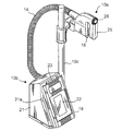
図2は、採水ディスペンサー10の外観を示している。ただし図2では、純水製造装置との接続に用いられる配管75や各種の配線は示されていない。採水ディスペンサー10は、大別すると、ヘッド部10aと、本体部10bと、本体部10bから垂直上方に延びてヘッド10aを取り外し可能に保持する支柱10cとから構成されており、ヘッド部10aと本体部10bとは可撓性を有する配管14によって接続されている。採水ディスペンサー10の使用形態として、例えば、実験台の上に整列して置かれた多数の試験管に対して次々と純水を注ぐために用いる、というものがある。このような用途に対応するために、ユーザーによって把持されて所望の位置に動かすことができるヘッド部10aを設けて、実際に純水の注ぎ口となるノズル16をヘッド部10aに設けるようにしている。ヘッド部10aには、ユーザーが把持するためのハンドル28あるいは取っ手が設けられている。また、ヘッド部10aを支柱10cに保持したまま小容量から大容量までのメスフラスコやメスシリンダーに純水を採水する必要もあるので、支柱10cにおけるヘッド10aの保持位置を可変とするとともに、支柱10cは十分な長さを有する必要がある。
ヘッド部10aは、本体部10bから配管14を介して送られてきた純水をノズル16から吐出するものであり、図1に示すように、ノズル16のほかに、配管14に接続する流路15と、流路15を流れる純水に対して紫外線を照射する紫外線照射部17を備えている。ノズル16は、流路15の末端に設けられている。紫外線照射部17は紫外線殺菌機構として機能するものであり、紫外線照射部17における紫外線源としては、紫外線LEDが用いられている。さらにヘッド部10aは、ユーザーの需要に応じて純水を吐出するために、ユーザーによって操作されるスイッチ18を備えている。ヘッド10aには、図2に示すように、ハンドル25を握ったユーザーがその指で容易に操作できる位置にボタン26が設けられている。ボタン26はスイッチ18に機械的に接続しており、ボタン26に対する操作によってスイッチ18が操作されるようになっている。
本体部10bには、サブユニット50からの配管75に一端が接続する配管11と、配管11に設けられた流量センサー(FI)12と、配管11の他端に取り付けられた電磁弁13と、採水ディスペンサー10の動作を制御する制御部20と、制御部20に接続する操作パネル19とが設けられている。電磁弁13は、制御部20からの駆動信号によって開弁する。操作パネル19は、ユーザーからの例えば採水量や採水モードの設定を受け付けるとともに、ユーザーに対して必要な表示を行うものである。採水モードとしては、例えば、定量モードや任意量モードがある。制御部20は、採水ディスペンサー10の全体の制御を行うものであり、例えば、ヘッド部10aのスイッチ18を介して入力したユーザーからの採水要求を受け付け、採水モードが定量モードである場合には、流量センサー12で検出される流量の累積値が設定値となるまで電磁弁13を開放することにより、その設定値で示される量の純水がヘッド部10aに送水されるようにする制御を行う。採水モードが任意量モードである場合には、制御部20は、スイッチ18が操作されている期間だけ電磁弁13を開放する制御を行う。また制御部20は、採水モードによらず、電磁弁13が開放しているときのみ、紫外線照射部17内の紫外線LEDが駆動されるように制御を行う。さらに制御部20は、不図示の配線により純水製造装置の主制御装置70に接続しており、主制御装置70から、純水製造装置の運転状態に関する情報、特に、TOC計62で測定されたTOC値、抵抗率計63で測定された抵抗率、温度計64で測定された温度値などの水質データを受ける取るように構成されている。制御部20は、受け取った水質データを所定のフォーマットで操作パネル19上に表示する。
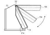
本体部10bを構成するこれらの要素のうち、配管11、流量センサー12、電磁弁13及び制御部20は、図2に示す筺体21の内部に設けられる。操作パネル19は、扁平な形状であって、その一端においてトルクヒンジ23を介して筺体21に取り付けられている。操作パネル19の一方の面には、液晶表示パネルとタッチセンサーとを一体化させたタッチパネル22が設けられている。タッチパネル22は、ユーザーに対して表示を行なう表示部として機能するとともに、タッチパネル22上の所定の位置に対してユーザーが触れることにより、ユーザーからの入力を受け付ける。トルクヒンジ23の回動軸は、トルクヒンジ23の位置での筺体21の表面と平行であり、その結果、図3において矢印で示すように、操作パネル19は、トルクヒンジ23を中心として筺体21に近づく方向及び筺体21から遠ざかる方向に回動する。筺体21に最も近づくときは、図3において実線で示すように、操作パネル19の裏面、すなわちタッチパネル22が設けられていない方の面が筺体21の前面の傾斜面21aに当接する。一方、最も遠ざかった状態では、図において破線19bに示すように、タッチパネル22の表面が水平になる。操作パネル19は、このような角度範囲内で回動可能であり、その表示面すなわちタッチパネル22の表面と水平面とがなす角度を調節可能である。
本実施形態で使用するトルクヒンジ23は、開き角を保持する機能を有するヒンジの1種であってフリーストップヒンジとも呼ばれ、回動軸の周りで回動させるためにしきい値以上のトルクを印加する必要があるものである。印加されるトルクがしきい値を下回るときにはトルクヒンジ3は動かずにそのままの状態すなわち姿勢を維持する。しきい値としては、操作パネル19の角度の調節を意図してユーザーが操作パネル19を動かすときには容易にトルクヒンジ23が回動し、かつ、入力のためにユーザーがタッチパネル22の表面を押圧した程度の力ではトルクヒンジ23は回動しないようなものを使用する。本実施形態では、例えばしきい値が1.08N・mであるものを使用する。その結果、重力も含めて操作パネル19からトルクヒンジ23に加わるトルクが1.08N・m未満であれば、トルクヒンジ23は回動せず、操作パネル19は、例えば図において破線19aで示すように、そのままの姿勢、すなわち筺体21に対する角度を維持する。
したがって本実施形態の採水ディスペンサー10を使用する場合、ユーザーは、立ったまま採水を行なうか椅子に座って採水を行なうかに応じて筺体21に対する操作パネル19の角度を調節することができる。これによりユーザーは、その作業姿勢に応じて最も見やすい角度で操作パネル19上の表示、例えば水質データなどの表示を確認することができるようになる。表示部である操作パネル19の筺体21に対する角度をこのように可変とする場合、筺体21の本体に操作用の押しボタンなどを設けると、押しボタンを押そうとする指と操作パネル19とが干渉して操作性が悪くなるおそれがあるが、本実施形態では、操作パネル19をタッチパネル22によって構成しているため、入力操作が行なわれる対象の操作パネル19となり、操作性を良好に維持することができる。
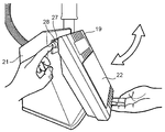
上述した実施形態の採水ディスペンサーでは、開き角を保持する機能を有するヒンジとしてトルクヒンジ23を使用しているが、本発明において操作パネル19を筐体21に取り付けるために使用可能なヒンジはトルクヒンジに限定されるものではなく、他のタイプのヒンジを使用することも可能である。図4に示す採水ディスペンサーは、上述した実施形態の採水ディスペンサーと同様のものであるが、開き角を保持する機能を有するヒンジとして可変式ストップヒンジ27を用いている点で、上述した実施形態の採水ディスペンサーとは異なっている。可変式ストップヒンジ27は、複数の開き角のいずれかを選択して開き角を固定することができ、かつ、開き角の再設定が可能なヒンジである。図示した例では、例えば15°刻みで開き角が設定された可動式ストップヒンジ27によって操作パネルが筐体21に取り付けられている。通常時には、可変式ストップヒンジ27によって操作パネル19と筐体21とがなす角は、設定されている複数の開き角の中の1つに固定されている。そして、可変式ストップヒンジ27の回動軸方向の先端に設けられたリリースボタン28を押し込むことにより、ヒンジ内部での係合状態が解除され、その状態では図において矢印で示すように、ヒンジの回動軸の周りで筐体21に対して操作パネル19を任意に回動させることができる。そして、リリースボタン28を押し込むのを止めると、可変式ステップヒンジ27に設定されている複数の開き角の中で、その時点での実際の開き角に一番近い開き角にヒンジが固定される。このように可変式ストップヒンジ27を使用すると、リリースボタン28に触れない限りヒンジは固定されるので、入力のために操作パネル19のタッチパネル22に触れたときにヒンジが緩んで操作パネル19が動くことを確実に防止でき、タッチパネル22を使用するときの操作性が向上する。
10 採水ディスペンサー
10a ヘッド部
10b 本体部
10c 支柱
19 操作パネル
20 制御部
21 筺体
22 タッチパネル
23 トルクヒンジ
27 可変式ストップヒンジ
10a ヘッド部
10b 本体部
10c 支柱
19 操作パネル
20 制御部
21 筺体
22 タッチパネル
23 トルクヒンジ
27 可変式ストップヒンジ
Claims (6)
- 純水の採水に用いられる採水ディスペンサーであって、
純水製造装置から純水が供給される本体部と、
前記純水を吐出するノズルを有し前記本体部に対して配管によって接続されたヘッド部と、
前記本体部に設けられた表示部と、
を備え、
前記表示部は、その表示面と水平面となす角度を調節可能であるように、開き角を保持する機能を有するヒンジにより前記本体部の筺体に対して取り付けられている採水ディスペンサー。 - 前記ヒンジはトルクヒンジである、請求項1に記載の採水ディスペンサー。
- 前記ヒンジは可変式ストップヒンジである、請求項1に記載の採水ディスペンサー。
- 前記表示部はタッチパネルである、請求項1乃至3のいずれか1項に記載の採水ディスペンサー。
- 前記本体部に設けられ、前記採水ディスペンサーを制御する制御部をさらに備える、請求項1乃至4のいずれか1項に記載の採水ディスペンサー。
- 一端が前記本体部に接続する支柱を有し、前記ヘッド部は前記支柱に取り外し可能に保持される、請求項1乃至5のいずれか1項に記載の採水ディスペンサー。
Applications Claiming Priority (2)
| Application Number | Priority Date | Filing Date | Title |
|---|---|---|---|
| JP2017-108053 | 2017-05-31 | ||
| JP2017108053 | 2017-05-31 |
Publications (1)
| Publication Number | Publication Date |
|---|---|
| WO2018221085A1 true WO2018221085A1 (ja) | 2018-12-06 |
Family
ID=64455703
Family Applications (1)
| Application Number | Title | Priority Date | Filing Date |
|---|---|---|---|
| PCT/JP2018/016628 Ceased WO2018221085A1 (ja) | 2017-05-31 | 2018-04-24 | 採水ディスペンサー |
Country Status (2)
| Country | Link |
|---|---|
| TW (1) | TW201904856A (ja) |
| WO (1) | WO2018221085A1 (ja) |
Cited By (1)
| Publication number | Priority date | Publication date | Assignee | Title |
|---|---|---|---|---|
| WO2024166596A1 (ja) * | 2023-02-06 | 2024-08-15 | オルガノ株式会社 | チューブクランプ及びチューブ保持器 |
Citations (4)
| Publication number | Priority date | Publication date | Assignee | Title |
|---|---|---|---|---|
| JPH0670831U (ja) * | 1993-03-05 | 1994-10-04 | 日本ミリポア株式会社 | 移動式超純水製造装置付属流し台 |
| JPH1153079A (ja) * | 1997-08-06 | 1999-02-26 | Hitachi Ltd | 携帯端末・拡張装置システム |
| JPH11206852A (ja) * | 1998-01-20 | 1999-08-03 | Tosho:Kk | 調剤装置 |
| JPH11354941A (ja) * | 1998-06-10 | 1999-12-24 | Seiko Epson Corp | 電子機器 |
-
2018
- 2018-04-24 WO PCT/JP2018/016628 patent/WO2018221085A1/ja not_active Ceased
- 2018-05-16 TW TW107116541A patent/TW201904856A/zh unknown
Patent Citations (4)
| Publication number | Priority date | Publication date | Assignee | Title |
|---|---|---|---|---|
| JPH0670831U (ja) * | 1993-03-05 | 1994-10-04 | 日本ミリポア株式会社 | 移動式超純水製造装置付属流し台 |
| JPH1153079A (ja) * | 1997-08-06 | 1999-02-26 | Hitachi Ltd | 携帯端末・拡張装置システム |
| JPH11206852A (ja) * | 1998-01-20 | 1999-08-03 | Tosho:Kk | 調剤装置 |
| JPH11354941A (ja) * | 1998-06-10 | 1999-12-24 | Seiko Epson Corp | 電子機器 |
Cited By (2)
| Publication number | Priority date | Publication date | Assignee | Title |
|---|---|---|---|---|
| WO2024166596A1 (ja) * | 2023-02-06 | 2024-08-15 | オルガノ株式会社 | チューブクランプ及びチューブ保持器 |
| JP7538905B1 (ja) | 2023-02-06 | 2024-08-22 | オルガノ株式会社 | チューブクランプ及びチューブ保持器 |
Also Published As
| Publication number | Publication date |
|---|---|
| TW201904856A (zh) | 2019-02-01 |
Similar Documents
| Publication | Publication Date | Title |
|---|---|---|
| US4190059A (en) | Apparatus for colonic lavage and specimen collection | |
| CN201139787Y (zh) | 内窥镜清洗消毒装置 | |
| US7578416B2 (en) | Water purification apparatus | |
| US9737861B2 (en) | Mixing systems for ready-to-use flush solutions | |
| JP2004500516A (ja) | 薬品計量ポンプ | |
| WO2018221085A1 (ja) | 採水ディスペンサー | |
| JP2019532314A5 (ja) | ||
| US8883000B2 (en) | Water purification apparatus and method | |
| US20080052094A1 (en) | Water dispensing systems and methods | |
| US9096445B2 (en) | Water purification apparatus | |
| JP6491279B2 (ja) | 採水ディスペンサー及びその補正方法 | |
| US11325822B2 (en) | Water dispenser and pure water producing apparatus | |
| US20210387871A1 (en) | Portable water purifying and dispensing unit | |
| CN215504959U (zh) | 一种精准智能氧流量与湿度感应装置 | |
| KR100775419B1 (ko) | 수압테스트기 | |
| JP6745321B2 (ja) | 採水ディスペンサー及び純水製造装置 | |
| JP6745320B2 (ja) | 採水ディスペンサー及び純水製造装置 | |
| JP2018202293A (ja) | 純水製造装置とその組み立て方法 | |
| JP2007057420A (ja) | 溶液供給装置 | |
| WO2018221084A1 (ja) | 紫外線ledの断線検出回路及び方法、採水ディスペンサーならびに純水製造装置 | |
| JP7369644B2 (ja) | 液体ディスペンサーとその流量調整方法 | |
| JP6956173B2 (ja) | 蒸発装置および方法 | |
| JP6745322B2 (ja) | 採水ディスペンサー及び純水製造装置 | |
| CN114288936A (zh) | 溶液配制器 | |
| WO2024166596A1 (ja) | チューブクランプ及びチューブ保持器 |
Legal Events
| Date | Code | Title | Description |
|---|---|---|---|
| 121 | Ep: the epo has been informed by wipo that ep was designated in this application |
Ref document number: 18808730 Country of ref document: EP Kind code of ref document: A1 |
|
| NENP | Non-entry into the national phase |
Ref country code: DE |
|
| 122 | Ep: pct application non-entry in european phase |
Ref document number: 18808730 Country of ref document: EP Kind code of ref document: A1 |
|
| NENP | Non-entry into the national phase |
Ref country code: JP |