WO2018207292A1 - 対象物認識方法、装置、システム、プログラム - Google Patents
対象物認識方法、装置、システム、プログラム Download PDFInfo
- Publication number
- WO2018207292A1 WO2018207292A1 PCT/JP2017/017721 JP2017017721W WO2018207292A1 WO 2018207292 A1 WO2018207292 A1 WO 2018207292A1 JP 2017017721 W JP2017017721 W JP 2017017721W WO 2018207292 A1 WO2018207292 A1 WO 2018207292A1
- Authority
- WO
- WIPO (PCT)
- Prior art keywords
- geometric
- geometric model
- joints
- geometric models
- models
- Prior art date
- Legal status (The legal status is an assumption and is not a legal conclusion. Google has not performed a legal analysis and makes no representation as to the accuracy of the status listed.)
- Ceased
Links
Images

Classifications
-
- G—PHYSICS
- G06—COMPUTING OR CALCULATING; COUNTING
- G06T—IMAGE DATA PROCESSING OR GENERATION, IN GENERAL
- G06T7/00—Image analysis
-
- G—PHYSICS
- G06—COMPUTING OR CALCULATING; COUNTING
- G06T—IMAGE DATA PROCESSING OR GENERATION, IN GENERAL
- G06T7/00—Image analysis
- G06T7/70—Determining position or orientation of objects or cameras
Definitions
- the present disclosure relates to an object recognition method, an object recognition apparatus, an object recognition system, and an object recognition program.
- Point cloud data including point cloud position information obtained from a sensor that obtains three-dimensional position information, and fitting a given geometric model (such as a cylinder or a cone) based on the point cloud data of one scene
- a given geometric model such as a cylinder or a cone
- an object of the present invention is to accurately recognize a joint or skeleton of an object based on point cloud data related to the object having a plurality of joints.
- point cloud data related to the surface of an object having a plurality of joints is acquired from a sensor that obtains three-dimensional position information, and a plurality of geometric models having axes are included in the point cloud data. And applying a fitting process for deriving respective positions and axial directions of a plurality of geometric models that apply to the point cloud data, and based on a result of the fitting process, the plurality of the models that apply to the point cloud data.
- two second geometries among the three joints of the object associated with each of the one or more first geometric models and the plurality of geometric models that apply to the point cloud data Recognizing at least one of two joints of the object associated with a skeleton of the object across a model, executed by a computer Object recognition method is provided.
- FIG. 10 is a schematic flowchart for explaining a determination method by a full width at half maximum by a length calculation unit 128; 3 is a schematic flowchart showing an example of the overall operation of the object recognition system 1. It is a schematic flowchart which shows an example of a site
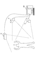
- FIG. 1 is a diagram schematically showing a schematic configuration of an object recognition system 1 according to an embodiment.
- FIG. 1 shows a target person S (an example of an object) for explanation.
- the object recognition system 1 includes a distance image sensor 21 and an object recognition apparatus 100.
- the distance image sensor 21 acquires a distance image of the subject S.
- the distance image sensor 21 is a three-dimensional image sensor, measures the distance by sensing the entire space, and acquires a distance image (an example of point cloud data) having distance information for each pixel like a digital image.
- the acquisition method of distance information is arbitrary.
- the distance information acquisition method may be an active stereo method in which a specific pattern is projected onto an object, read by an image sensor, and the distance is acquired by a triangulation method from the geometric distortion of the projection pattern.
- a TOF (Time-of-Flight) method may be used in which laser light is irradiated, reflected light is read by an image sensor, and a distance is measured from the phase shift.
- the distance image sensor 21 may be installed in a manner in which the position is fixed, or may be installed in a manner in which the position is movable.
- the object recognition device 100 recognizes the joint and skeleton of the subject S based on the distance image obtained from the distance image sensor 21. This recognition method will be described in detail later.
- the target person S is a person or a humanoid robot, and has a plurality of joints. In the following, it is assumed that the target person S is a person as an example.
- the target person S may be a specific individual or an unspecified person depending on the application. For example, when the use is an analysis of a movement during a competition such as gymnastics, the target person S may be an athlete.
- the distance image sensor 21 is preferably a target as shown schematically in FIG. A plurality of points are installed so that point cloud data close to the three-dimensional shape of the person S can be obtained.
- the object recognition device 100 may be realized in the form of a computer connected to the distance image sensor 21.
- the connection between the object recognition apparatus 100 and the distance image sensor 21 may be realized by a wired communication path, a wireless communication path, or a combination thereof.
- the object recognition apparatus 100 when the object recognition apparatus 100 is in the form of a server that is relatively remote to the distance image sensor 21, the object recognition apparatus 100 may be connected to the distance image sensor 21 via a network.
- the network may include, for example, a wireless communication network of a mobile phone, the Internet, World Wide Web, VPN (virtual private network), WAN (Wide Wide Area Network), a wired network, or any combination thereof.
- the wireless communication path is based on short-range wireless communication, Bluetooth (registered trademark), Wi-Fi (Wireless Fidelity), or the like. It may be realized. Further, the object recognition device 100 may be realized in cooperation with two or more different devices (for example, a computer and a server).
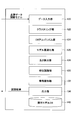
- FIG. 2 is a diagram illustrating an example of a hardware configuration of the object recognition apparatus 100.
- the object recognition apparatus 100 includes a control unit 101, a main storage unit 102, an auxiliary storage unit 103, a drive device 104, a network I / F unit 106, and an input unit 107.
- the control unit 101 is an arithmetic device that executes a program stored in the main storage unit 102 or the auxiliary storage unit 103, receives data from the input unit 107 or the storage device, calculates, processes, and outputs the data to the storage device or the like. To do.
- the control unit 101 may include, for example, a CPU (Central Processing Unit) and a GPU (Graphics Processing Unit).
- the main storage unit 102 is a ROM (Read Only Memory), a RAM (Random Access Memory), or the like, and a storage device that stores or temporarily stores programs and data such as an OS and application software that are basic software executed by the control unit 101 It is.
- ROM Read Only Memory
- RAM Random Access Memory
- the auxiliary storage unit 103 is an HDD (Hard Disk Drive) or the like, and is a storage device that stores data related to application software.
- HDD Hard Disk Drive
- the drive device 104 reads the program from the recording medium 105, for example, a flexible disk, and installs it in the storage device.
- the recording medium 105 stores a predetermined program.
- the program stored in the recording medium 105 is installed in the object recognition device 100 via the drive device 104.
- the installed predetermined program can be executed by the object recognition apparatus 100.
- the network I / F unit 106 is an interface between the target object recognition apparatus 100 and a peripheral device having a communication function connected via a network constructed by a data transmission path such as a wired and / or wireless line.
- the input unit 107 includes a keyboard having cursor keys, numeric input, various function keys, and the like, a mouse, a slice pad, and the like.
- the input unit 107 may correspond to other input methods such as voice input and gestures.
- various processes described below can be realized by causing the object recognition apparatus 100 to execute a program. It is also possible to record the program on the recording medium 105 and cause the object recognition apparatus 100 to read the recording medium 105 on which the program is recorded, thereby realizing various processes described below.
- various types of recording media can be used as the recording medium 105.
- a recording medium that records information optically, electrically, or magnetically such as a CD-ROM, a flexible disk, or a magneto-optical disk, or a semiconductor memory that electrically records information, such as a ROM or flash memory It may be.
- the recording medium 105 does not include a carrier wave.
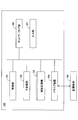
- FIG. 3 is a block diagram illustrating an example of functions of the object recognition apparatus 100.
- the object recognition apparatus 100 includes a data input unit 120 (an example of an acquisition unit), a clustering unit 122, an EM algorithm unit 124 (an example of a fitting processing unit), a model optimization unit 126, and a length calculation unit 128. including.
- the object recognition apparatus 100 further includes a part recognition unit 130, a skeleton shaping unit 132 (an example of a recognition processing unit), and an output unit 134.
- Each unit 120 to 134 can be realized by the control unit 101 illustrated in FIG. 2 executing one or more programs stored in the main storage unit 102.
- a part of the function of the object recognition apparatus 100 may be realized by a computer that can be incorporated in the distance image sensor 21.
- the object recognition apparatus 100 includes a geometric model database 140 (indicated as “geometric model DB” in FIG. 3).
- the geometric model database 140 may be realized by the auxiliary storage unit 103 illustrated in FIG.
- the distance image (hereinafter referred to as “point cloud data”) is input from the distance image sensor 21 and the joint model to be used is input to the data input unit 120.
- the point cloud data is as described above, and may be input for each frame period, for example.
- the point cloud data may include a set of distance images from the plurality of distance image sensors 21.
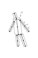
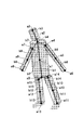
- the joint model to be used is an arbitrary model related to the subject S, for example, a model represented by a plurality of joints and a skeleton (link) between the joints.
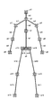
- a joint model as shown in FIG. 4 is used.
- the joint model as shown in FIG. 4 is a 16-joint model having one head, three torso parts (torso parts), both arm parts, and both leg parts. Others are defined as joints at both ends and midpoint.
- the joint model includes 16 joints a0 to a15 and 15 skeletons b1 to b15 (or also referred to as “parts b1 to b15”) connecting the joints.
- the joints a4 and a7 are left and right shoulder joints, and the joint a2 is a joint related to the cervical spine.
- the joints a14 and a15 are the left and right hip joints, and the joint a0 is a joint related to the lumbar spine.
- the skeletons b14 and b15 related to the hip joint and the skeletons b4 and b7 related to the shoulder joint are skeletons (hereinafter referred to as “hidden skeletons”) that cannot be accurately recognized only by fitting using a geometric model described later. Also called).
- hidden skeletons skeletons
- the clustering unit 122 clusters the point cloud data input to the data input unit 120, performs fitting for each cluster, and obtains an initial fitting result (initial value used for fitting using a geometric model described later).
- Kmeans ++ method or the like can be used as a clustering method.
- the number of clusters given to the clustering unit 122 may be manually input, or a predetermined number corresponding to the skeleton model may be used.
- the predetermined number corresponding to the skeleton model is, for example, a value obtained by subtracting the number of parts related to the hidden skeleton from the total number of parts related to the skeleton model. That is, in the case of the 16 joint (15 sites) model shown in FIG.
- the predetermined number that is the initial number of clusters is “11”.
- a part of the model is rejected according to the fitting result by clustering.
- a rejection method a method may be used in which a threshold is set for the data sum of the posterior distribution, which is an expected value of the number of point cloud data that can be explained by the model, and the model below the threshold is rejected.
- the clustering unit 122 can obtain an initial value used for fitting using a geometric model described later by performing fitting again with the number of clusters.
- an initial value used for fitting may be acquired by the machine learning unit.
- the machine learning unit performs label division (region recognition) on 15 sites based on the point cloud data input to the data input unit 120.
- a random forest may be used as the machine learning method, and the difference between the distance values of the target pixel and the surrounding pixels may be used as the feature amount.
- a method of performing multi-class classification of each pixel using a distance image as an input may be used.
- feature quantities other than the difference in distance value may be used, or deep learning (Deep Learning) in which learning is performed including parameters corresponding to the feature quantities may be used.
- the EM algorithm unit 124 sets the parameter ⁇ by the EM algorithm based on the point cloud data input to the data input unit 120, the geometric model in the geometric model database 140, and the initial value of the fitting obtained by the clustering unit 122. To derive. The reason why the initial value of fitting obtained by the clustering unit 122 is used is that it is useful to give an initial value close to a solution to some extent in the EM algorithm.
- the initial value is an initial value related to the number of parts M and a parameter ⁇ described later.
- the geometric model in the geometric model database 140 is, for example, a cylinder, and a case where it is mainly a cylinder will be described below. The possibility of other geometric models will be described later.
- the EM algorithm unit 124 determines the parameter ⁇ so that the point cloud data x n is most concentrated on the surface of the geometric model.
- the point group data x n is a set (x 1 , x 2 ,..., X N ) of N points (for example, position vectors) expressed by three-dimensional spatial coordinates (x, y, z). is there.
- the x component and y component of the spatial coordinates are values of two-dimensional coordinates in the image plane
- the x component is a horizontal component
- the y component is a vertical component.
- the z component represents a distance.
- the part m is a part (part) of the point cloud data for each geometric model, and is a part associated with the geometric model and the part of the subject S along with the geometric model.
- the part m may be associated with two parts of the subject S at the same time. For example, in a state where the subject S is stretching the elbow, a part (part b6 or part b9 in FIG. 4) from the elbow joint to the wrist joint (offspring side joint) and the elbow joint to the shoulder joint ( A part up to the ancestor side joint (part b5 or part b8 in FIG. 4) can be one part m.
- r m and ⁇ 2 are scalars, and c m 0 and e m 0 are vectors.
- e m 0 is a unit vector. That is, e m 0 is a unit vector representing the direction of the axis of the cylinder.
- the position c m 0 is a position vector related to the position of an arbitrary point on the axis of the cylinder.
- the length (height) in the axial direction of the cylinder is indefinite.
- the orientation e m 0 of the geometric model is the same concept as the axial direction of the geometric model.
- p (x n ) is a mixed probability distribution model of the point cloud data x n , as described above, ⁇ 2 is a variance, and M is the number of clusters obtained by the clustering unit 122. .
- the corresponding log likelihood function is as follows.
- N is the number of data (the number of data included in the point cloud data related to one frame).
- Equation 2 is a log-likelihood function of a mixed Gaussian model
- an EM algorithm or the like can be used.
- the EM algorithm unit 124 derives a parameter ⁇ and a variance ⁇ 2 that maximize the log likelihood function based on the EM algorithm.
- the surface residual ⁇ m (x n , ⁇ ) is expressed such that the exponent part in Equation 2 is a square difference. Specifically, It is as follows.
- the EM algorithm is an iteration of an E step for calculating an expected value and an M step for maximizing the expected value.
- the EM algorithm unit 124 calculates the following posterior distribution p nm .
- the EM algorithm unit 124 derives a parameter ⁇ and a variance ⁇ 2 that maximize the following expected value Q ( ⁇ , ⁇ 2 ).
- the posterior distribution p nm is treated as a constant.
- P is the sum of all parts of the data sum of the posterior distribution p nm (hereinafter, also referred to as “the sum of all parts of the data sum of the posterior distribution p nm ”), and is as follows.
- the expected value Q ( ⁇ , ⁇ 2) estimate of the variance sigma 2 to maximize the sigma 2 * is as follows.
- the estimated value r * m of the thickness r m can be directly minimized as follows.
- Equation 9 is an average operation using the posterior distribution p nm , and is as follows for an arbitrary tensor or matrix A nm .
- the estimated value e * m 0 of the direction e m 0 is the principal component of the point cloud data, it can be derived based on the principal component analysis. That is, the estimated value e * m 0 of the direction e m 0 can be obtained as the direction of the eigenvector having the largest eigenvalue of the following variance-covariance matrix ⁇ xx .
- ⁇ x n > p has dependency on the part m and corresponds to the center of gravity (center) of the geometric model (cylinder) related to the part m.
- the variance-covariance matrix ⁇ xx is also specific to the part m and corresponds to the direction of the geometric model (cylinder) related to the part m.
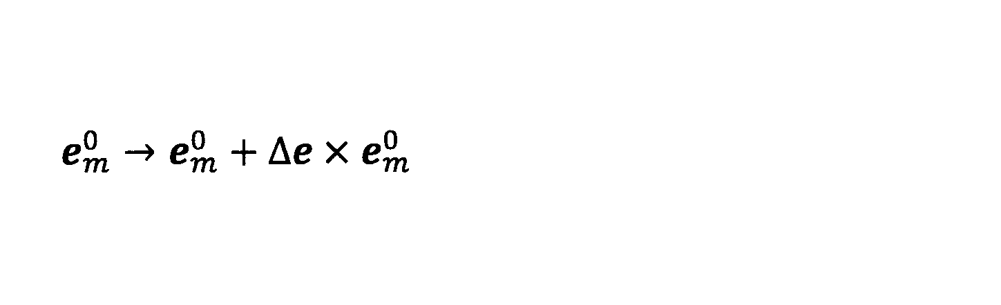
- the direction e m 0 may be derived by linear approximation. Good.
- the update formula based on the minute rotation is defined in such a manner that the norm is preserved, and is as follows.
- ⁇ e is a minute rotation vector.
- the estimated value ⁇ e * of ⁇ e is obtained by differentiating the equation of Formula 8 by ⁇ e, and is as follows.
- Equation 14 represents transposition.
- e 1 and e 2 are unit vectors orthogonal to the direction e m 0 .
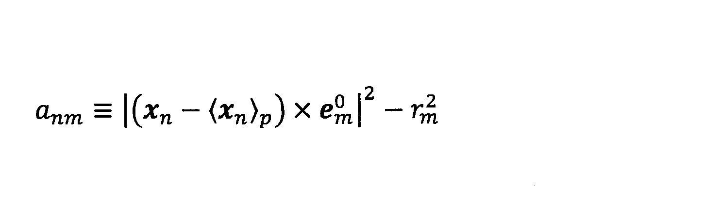
- a nm and b nm in Equation 13 are as follows (regardless of the notation of joints a0 to a15 and skeletons b1 to b15 shown in FIG. 4).
- the estimated value e * m 0 of the direction e m 0 is as follows.
- the inverse matrix of the covariance matrix ⁇ yy and the vector ⁇ y2y (subscript “y 2 y”) are as follows.
- the EM algorithm unit 124 first obtains the estimated value c * m 0 of the position c m 0 and then obtains the estimated value r * m of the thickness r m .
- the thickness r m of the parameters ⁇ may be manually entered by the user, the shape information It may be set automatically based on this.
- the EM algorithm unit 124 derives the remaining elements (position c m 0 and direction e m 0 ) of the parameter ⁇ .
- the other measurement may be a precise measurement in advance or may be executed in parallel.
- the model optimizing unit 126 has the best fit at the time of fitting among the plurality of types executed.
- a geometric model of is derived.
- the plurality of types of geometric models include geometric models other than cylinders, which are at least one of a cone, a trapezoidal column, an elliptical column, an elliptical cone, and a trapezoidal elliptical column.
- the multiple types of geometric models related to one part may not include a cylinder.
- the plurality of types of geometric models related to one part may be different for each part.
- a single fixed geometric model may be used without using a plurality of types of geometric models.
- the EM algorithm unit 124 first fits each part using a cylindrical geometric model. Next, the EM algorithm unit 124 switches a geometric model related to a certain part from a cylinder to another (for example, a cone), and performs fitting to the same part. Then, the model optimizing unit 126 selects the geometric model having the largest logarithmic likelihood function as the type of geometric model having the best fit. The model optimizing unit 126 may select the geometric model having the largest sum of all the parts of the posterior distribution data sum as the geometric model having the best fit, instead of the geometric model having the largest log likelihood function. Good.
- the surface residual ⁇ m (x n , ⁇ ) may be expressed as:
- the position c m 0 corresponds to the vertex position
- the direction e m 0 is a unit vector of the central axis.
- the vector nm is a normal vector at a certain point on the surface of the cone.
- the surface residual ⁇ m (x n , ⁇ ) may be the same as in the case of a cone. That is, in the case of a trapezoidal column, it can be expressed by defining a distribution with respect to a part of a cone.
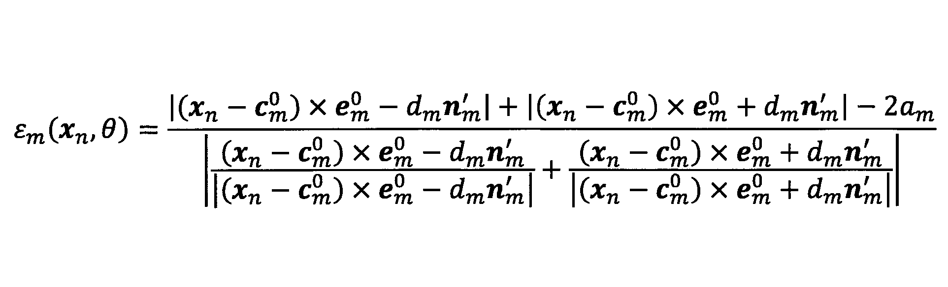
- the surface residual ⁇ m (x n , ⁇ ) may be expressed as follows.
- d m is the focal length
- a m is the length of the major axis of the cross-section of an ellipse
- n m ' is the unit vector in the long axis direction.
- the position c m 0 corresponds to the position on the axis
- the direction e m 0 is a unit vector of the axis of the elliptic cylinder (axial direction).
- the surface residual ⁇ m (x n , ⁇ ) may be expressed as follows.
- ⁇ m1 and ⁇ m2 are inclination angles in the major axis and minor axis directions, respectively.
- the position c m 0 corresponds to the vertex position, and the direction e m 0 is a unit vector of the central axis.
- the surface residual ⁇ m (x n , ⁇ ) may be the same as in the case of the elliptical cone.
- the EM algorithm unit 124 preferably performs a finite length process.
- the finite length process is a process of calculating the posterior distribution p nm only for data satisfying a predetermined condition among the point cloud data x n and setting the posterior distribution p nm to 0 for other data.
- the finite length process is a process for preventing data irrelevant to the part m from being mixed, and the predetermined condition is set so that data irrelevant to the part m can be excluded. Thereby, it can suppress that the point cloud data which should not be actually related influences analysis.
- the data satisfying the predetermined condition may be data satisfying the following expression, for example.
- l m 0 is an input length related to the part m
- ⁇ is a margin (for example, 1.2).
- the input length l m 0 can be manually input, or may be set based on the shape information of the subject S obtained by other measurement.
- the length calculation unit 128 calculates the length (part) from the center to the end of the geometric model.
- the length parameter l m corresponding to (the length from the center of m to the end) is derived.
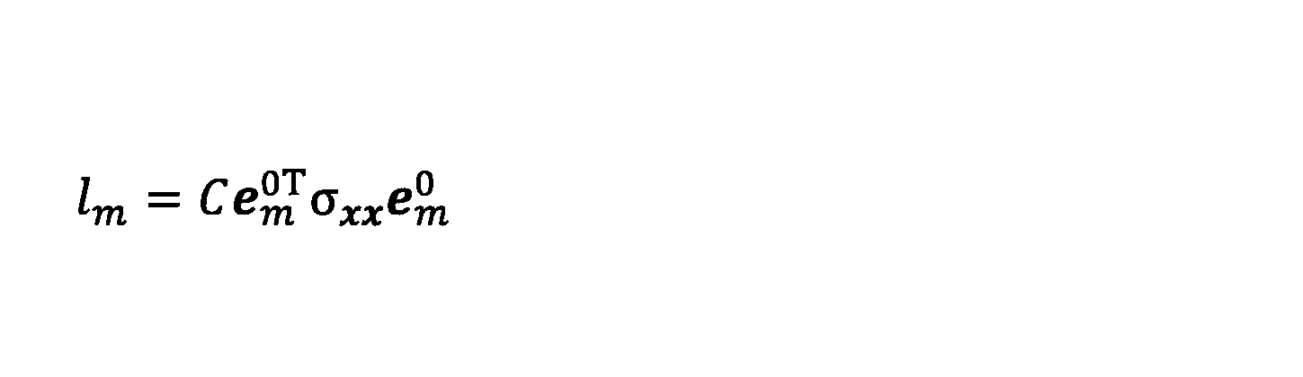
- the length calculation unit 128 may calculate the length parameter l m of the part m using the variance-covariance matrix ⁇ xx as follows.
- C is a constant multiple correction value.
- the length calculation section 128, the length parameter l m site m may be calculated by determination by the full width at half maximum.
- the full width at half maximum refers to the interval up to where the number of data is halved compared to where there is a lot of data.
- the length calculation unit 128 derives a length parameter by finding the “cut” of the part m.
- the length calculation unit 128 finely cuts the part m along the axial direction in the form of a ring whose normal is the axial direction related to the direction e m 0 , and counts the number of data contained therein.
- a point where the value is equal to or less than a predetermined threshold is defined as a “break”. Specifically, in the determination based on the full width at half maximum, the predetermined threshold is half the maximum value of the count value, but may be a value other than half, such as 0.1 times the maximum value of the count value.
- FIG. 5 is a diagram schematically showing a derivation result (fitting result by a geometric model) by the EM algorithm unit 124
- FIG. 6 is a schematic flowchart for explaining a determination method by the full width at half maximum by the length calculation unit 128. .
- the head and the torso are each fitted with a single cylinder, and both the arms and the legs are fitted with a single cylinder.
- a method for calculating the length parameter l m (l + m and l ⁇ m ) of the part m will be described as a representative case where the arm portion of the subject S is the part m.
- the arm is recognized as one part by the EM algorithm part 124 because the elbow joint is extended (it is applied by one geometric model). .
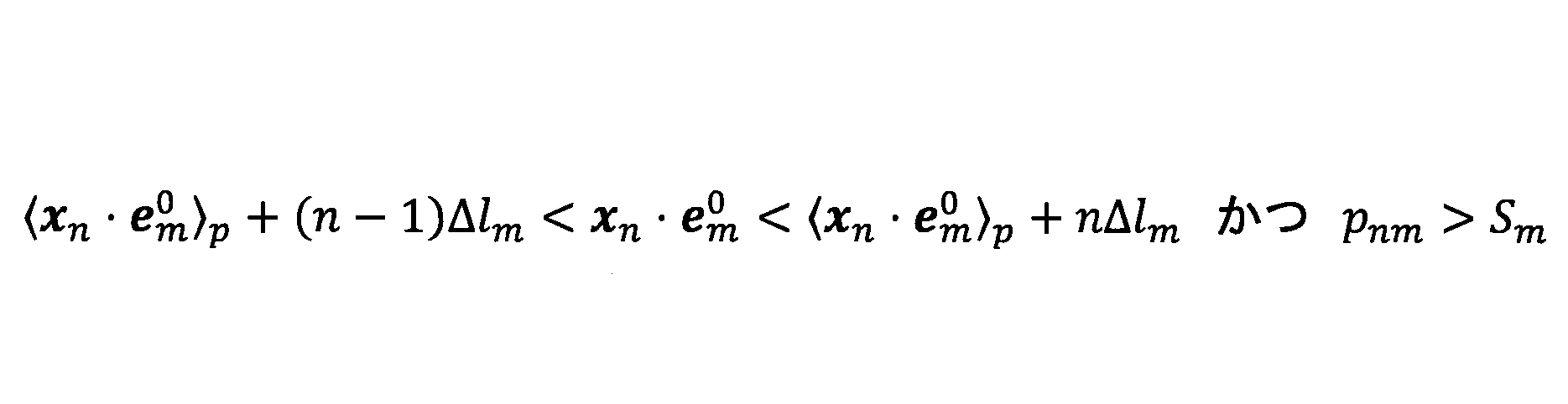
- step S602 the length calculation unit 128 counts the number of data satisfying the following condition among the point cloud data xn .
- ⁇ X n ⁇ e m 0 > p corresponds to the center of the part m.
- ⁇ l m corresponds to the width of the ring cut (width along the axial direction e m 0 ), and is, for example, 0.01 l m 0 .
- l m 0 is the input length related to the part m as described above.
- S m is a threshold for the posterior distribution p nm , and is 0.1, for example.
- step S604 the length calculation unit 128 sets the reference value Cref based on the count number obtained in step S602. For example, the length calculation unit 128 sets the count obtained in step S602 as the reference value Cref.
- step S606 n is incremented by “1”.
- step S608 the length calculation unit 128 counts the number of data satisfying the following condition in the point cloud data xn . That is, the length calculator 128 in the next section shifted by .DELTA.l m, counts the number of the following conditions data.
- step S610 the length calculation unit 128 determines whether or not the number of data counted in step S608 is equal to or less than a predetermined number times (for example, 0.5 times) the reference value Cref. If the determination result is “YES”, the process proceeds to step S612, and otherwise, the process from step S606 is repeated.
- a predetermined number times for example, 0.5 times
- step S620 to step S632 the length calculation unit 128 proceeds in the reverse direction (ancestor side), and in the same way, from the center to the ancestor side end of the part m shown in FIG.
- the length parameter l - m of is calculated.
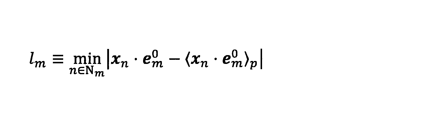
- the length calculation unit 128, as follows, may be calculated length parameter l m site m.
- N m is a subset of n defined below, and is a set of n whose posterior distribution p nm is smaller than a certain threshold value p m th .
- the threshold value p m th is, for example, as follows.
- the subset N m is a set of data that does not belong to the part m in the point cloud data x n . Therefore, the length calculation section 128, among the subsets N m, the distance from the center (number 29
- ) to data is minimized Based on this, the length parameter lm of the part m is calculated.
- Region recognition unit 130 a derivation result of the parameters of site m (r m, c m 0 , and e m 0), on the basis of the derivation result of the length parameter l m site m, performs a part recognition process.
- the part recognition process includes recognizing the correspondence between the part m and each part of the subject S (see the parts b1 to b15 in FIG. 4).
- the position of the end of the part m on the axis (the end that determines the length parameter l m ) can be derived.
- the position ⁇ m 0 of the end portion on the axis of the part m satisfies the following.
- Equation 32 the second term on the right side of Equation 32 is as follows at the end on the ancestor side and the end on the descendant side.
- l ⁇ m is the center of the part m Is a length parameter from to the ancestor side, and is calculated by the length calculation unit 128 as described above.
- ⁇ is a constant, and may be 1, for example.
- a “joint point” refers to a representative point related to a joint (a point representing a position related to a joint), and an end (position) of the part m that can be derived in this way also corresponds to the joint point.
- Region recognition unit 130 by using the thickness r m, identifying the main site.
- the main part is the part with the largest thickness, and is the trunk of the subject S in this embodiment.
- the part recognizing unit 130 recognizes the thickest part or two adjacent first and second thickest parts whose thickness difference is less than a predetermined value as the main part of the object. Specifically, when the difference between the first largest part m1 and the second largest part m2 is less than a predetermined value, the part recognition unit 130 determines which part m1, m2 Is also identified as a torso. The predetermined value is a matching value corresponding to the difference in thickness between the parts m1 and m2. On the other hand, when the difference between the first largest part m1 and the second largest part m2 is equal to or greater than a predetermined value, the part recognition unit 130 converts only the first largest part m1 into the trunk (part b1 + part. identified as b2).
- the site recognition unit 130 sets a “cut flag” for the site ml.
- the significance of the disconnect flag will be described later. Accordingly, for example, in FIG. 4, even when the part b1 and the part b2 are straightly extended according to the posture of the subject S, the part b1 and the part b2 can be recognized as the trunks related to the part m1 and the part m2. .
- the part recognizing unit 130 determines (identifies) a joint point in the vicinity of the bottom of the torso after identifying the main part (torso).
- the part recognition unit 130 For the bottom surface of the body part, the part recognition unit 130 has an end part on the body part side in a minute cylinder (or an elliptical column or a trapezoidal column) set at the position of the end part on the bottom surface side of the body part.
- the two parts ml and mr to which the position of belong are specified.
- a predetermined value may be used for the height of the minute cylinder.
- the part recognition unit 130 divides the parts ml and mr into the part related to the left leg (refer to part b10 or part b10 + b11 in FIG. 4) and the part related to the right leg (refer to part b12 or part b12 + b13 in FIG. 4).
- the part recognizing part 130 When the part recognizing part 130 identifies the part ml related to the left leg part, the part recognizing part 130 includes a body part in a sphere (hereinafter also referred to as “connected sphere”) set at the position of the end part far from the body part in the part ml. It is determined whether or not there is a part having an end position on the side close to. A predetermined value may be used for the diameter of the connecting sphere. If there is a part ml2 having the position of the end close to the torso in the connecting sphere, the part recognition unit 130 recognizes the part ml as the thigh b10 of the left leg, and the part ml2 This is recognized as the shin b11 of the left leg.
- the part recognition unit 130 recognizes the part ml as a part including both the thigh and shin of the left leg. To do.
- the site recognition unit 130 sets a “cut flag” for the site ml. Thereby, for example, in FIG. 4, even when the parts b ⁇ b> 10 and b ⁇ b> 11 extend straight according to the posture of the subject S, the parts b ⁇ b> 10 and b ⁇ b> 11 can be recognized as parts related to the left leg.
- the part recognizing unit 130 identifies the part mr related to the right leg part, the part close to the body part in the sphere (connected sphere) set at the position of the end part far from the body part in the part mr. It is determined whether or not there is a part having the position of the end. A predetermined value may be used for the diameter of the connecting sphere.
- the part recognition unit 130 recognizes the part mr as the thigh b12 of the right leg, and the part mr2 This is recognized as the right leg shin b13.
- the part recognition unit 130 recognizes the part mr as a part including both the thigh and shin of the right leg. To do. In this case, the part recognition unit 130 sets a “cut flag” for the part mr. Thereby, for example, in FIG. 4, even when the parts b12 and b13 extend straight according to the posture of the subject S, the parts b12 and b13 can be recognized as parts related to the right leg.
- the part recognition part 130 will determine (identify) the joint point in the side surface vicinity of a trunk
- the site recognizing unit 130 is located on the side surface in the axial direction (principal axis) of the torso, and the two joint points closest to the head side surface are the base joint points of the left and right arms (joint points related to the shoulder joint). Identify as.
- the part recognizing unit 130 identifies a joint point included in a thin torus (a torus related to a cylinder) on the side surface of the trunk as a joint point of the base of the arm. A predetermined value may be used as the thickness of the torus.
- the part recognition unit 130 divides the parts mlh and mrh including the base joint points of the left and right arm parts into the part related to the left hand (see part b5 or part b5 + b6 in FIG. 4) and the part related to the right hand (in FIG. 4). Recognized as part b8 or part b8 + b9).
- the part recognition unit 130 When the part recognition unit 130 identifies the part mlh related to the left hand, the position of the end part on the side close to the trunk part in the sphere (connected sphere) set to the position of the end part far from the trunk part in the part mlh. It is determined whether or not there is a part having. A predetermined value may be used for the diameter of the connecting sphere. Then, when there is a part mlh2 having the position of the end on the side close to the trunk part in the connecting sphere, the part recognition unit 130 recognizes the part mlh as the upper arm part b5 of the left hand, and the part mlh2 Recognized as the left arm forearm b6.
- the part recognition unit 130 recognizes the part mlh as a part including both the upper arm part and the forearm part of the left hand. To do. In this case, the part recognition unit 130 sets a “cut flag” for the part mlh. Thereby, for example, in FIG. 4, even when the parts b5 and b6 extend straight in accordance with the posture of the subject S, the parts b5 and b6 can be recognized as the parts related to the left hand.
- the part recognizing part 130 identifies the part mrh related to the right hand, the end on the side close to the torso is within the sphere (connected sphere) set at the position of the end far from the torso in the part mrh. It is determined whether or not there is a part having the position of the part. A predetermined value may be used for the diameter of the connecting sphere. And when the part mrh2 which has the position of the edge part near the trunk
- the part recognition unit 130 recognizes the part mrh as a part including both the upper arm part and the forearm part of the right hand. To do. In this case, the part recognition unit 130 sets a “cut flag” for the part mrh. Thereby, for example, in FIG. 4, even when the parts b8 and b9 are straightly extended according to the posture of the subject S, the parts b8 and b9 can be recognized as the parts related to the right hand.
- the skeleton shaping unit 132 performs a cutting process, a joining process, and a connecting process as the skeleton shaping process.
- the cutting process is a process of separating one part into two further parts.
- the part to be separated is a part of the part m in which the above-described cutting flag is set.
- the geometric model related to the part to be cut (that is, the geometric model related to the part for which the above-described cutting flag is set) is an example of the first geometric model.
- the parts for which the cutting flag is set are, for example, the parts recognized as one part by the fitting by the geometric model when the straight flag is extended, such as the upper arm part and the forearm part (see parts b5 and b6 in FIG. 4). It is.
- the cutting process separates such originally two sites into two further sites.
- Equation 32 the second term on the right side of Equation 32 is as follows. Note that the derivation results of c m 0 and e m 0 are used to derive the intermediate joint point.
- ⁇ is a constant, and may be 1, for example.
- ⁇ may be set based on the shape information of the subject S obtained by other measurement.
- the cutting process even when the part m originally includes a part consisting of two parts, it is possible to derive three joint points by cutting into two further parts. Therefore, for example, even when the legs are stretched and the elbows and knees are straightened, the three joint points can be derived by the cutting process.
- the joining process is a process of generating a hidden skeleton as a straight line connecting two joint points related to two predetermined parts m.
- the geometric model related to the predetermined two parts m to be combined is an example of the second geometric model.
- the hidden skeletons include skeletons b14 and b15 related to the hip joint and skeletons b4 and b7 related to the shoulder joint.
- the joint point a0 on the bottom surface side of the part b1 and the joint point a14 on the trunk part side of the part b10 correspond to the two joint points to be combined.
- the predetermined two joints correspond to the joint point a0 on the bottom surface side of the part b1 and the joint point a15 on the trunk part side of the part b12.
- the predetermined two joints correspond to the joint point a2 on the head side of the part b2 and the joint point a4 on the trunk part side of the part b5.
- the predetermined two joints correspond to a joint point a2 on the head side of the part b2 and a joint point a7 on the trunk part side of the part b8.
- a hidden skeleton (a straight line corresponding to the link) can be derived by the coupling process.
- the direction of the straight line related to the hidden skeleton may be used as the direction es 0 of the part s related to the hidden skeleton, and the position on the straight line may be the position c s 0 of the part s related to the hidden skeleton. It may be used as
- connection process is a process of integrating (connecting) joint points (common joint points) related to the same joint that can be derived from geometric models related to different parts into one joint point.
- the joint points to be connected are, for example, two joint points in the connecting sphere described above (joint points related to the joints a5, a8, a10, and a12 in FIG. 4).
- Such connection processing relating to the arm portion and the leg portion is executed when the cutting flag is not set.
- the other joint points to be connected are related to the joint point of the neck, and are two joint points (joint points related to the joint a2 in FIG. 4) obtained from both the geometric model of the head and the geometric model of the torso. is there.
- the point of articulation other consolidated in case of identification thickness r m is 1 largest part m1 and the second largest site m2 and as each barrel, the joint between the portions m1 and site m2 Points (joint points related to the joint a1 in FIG. 4). That is, the connection process related to the body is executed when the cutting flag is not set.
- connection process may be a process of simply selecting one of the joint points. Or, the method using the average value of two joint points, the method using the value of the part with the larger data sum of the posterior distribution of the two parts related to the two joint points, the data sum of the posterior distribution A method using a weighted value may be used.
- the skeleton shaping unit 132 preferably performs further symmetrization processing as the skeleton shaping processing.
- the symmetrization process is a process of correcting the parameters symmetrically with respect to the parts that are essentially symmetrical.
- symmetrical parts are, for example, left and right arm parts and left and right leg parts.
- the skeleton shaping unit 132 sets the largest sum of the posterior distribution data for the thickness r m and the length parameter l m of the parameter ⁇ . You may unify.
- the thickness r m and length parameters l m of the left leg For example if the data sum of the posterior distribution of the left leg is greater than the sum of data of the posterior distribution of the right leg, the thickness r m and length parameters l m of the left leg, the thickness of the right leg portion It is to correct the r m and length parameters l m.
- the thickness r m and length parameters l m By utilizing the left-right symmetry, it is possible to improve the accuracy of the thickness r m and length parameters l m.
- the output unit 134 outputs the skeleton information of the subject S (indicated as “recognition result” in FIG. 3) to a display device or the like (not shown).
- the output unit 160 may output the skeleton information of the subject S approximately in real time for each frame period.
- the output unit 160 may output the skeleton information in time series in non-real time for the purpose of explaining the movement of the subject S.
- the skeletal information may include information that can specify the positions of the joints a0 to a15.
- the skeleton information may include information that can specify the position, orientation, and thickness of the skeletons b1 to b15.
- the use of the skeleton information is arbitrary, but may be used to derive the skeleton information in the next frame period.
- the skeletal information may ultimately be used for analysis of the movement of the subject S during competition such as gymnastics. For example, in the analysis of the movement of the subject S at the time of gymnastics competition, technique recognition and technique quantification (score etc.) based on skeleton information may be realized.
- the movement of the target person S assumed to be an operator may be analyzed and used for a robot program. Alternatively, it can be used for user interface by gestures, personal identification, quantification of skilled techniques, and the like.
- the cutting process is performed on the result obtained by performing the fitting using the geometric model.
- the joint that connects the two parts can be accurately recognized.
- the combining process is performed on the result obtained by performing the fitting using the geometric model.
- the joint or skeleton of the subject S can be accurately recognized based on the point cloud data of the subject S.
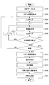
- FIG. 7 is a schematic flowchart showing an example of the overall operation of the object recognition system 1
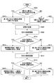
- FIG. 8 is a schematic flowchart showing an example of the part recognition process.
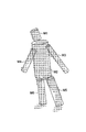
- 9A and 9B are explanatory diagrams of the processing of FIG.
- point group data x n relating to a certain temporary point (one scene) is shown.
- step S700 the point cloud data xn relating to a certain temporary point is input to the data input unit 120.
- step S702 the clustering unit 122 acquires an initial value used for fitting using a geometric model based on the point cloud data xn obtained in step S700.
- the details of the processing (initial value acquisition method) of the clustering unit 122 are as described above.
- step S704 the EM algorithm unit 124 executes the E step of the EM algorithm based on the point cloud data xn obtained in step S700 and the initial value obtained in step S702. Details of the E step of the EM algorithm are as described above.
- step S710 the EM algorithm unit 124 determines whether there is an unprocessed part, that is, whether j ⁇ M. If there is an unprocessed part, the process from step S706 is repeated through step S711. If there is no unprocessed part, the process proceeds to step S712.
- step S711 the EM algorithm unit 124 increments j by “1”.
- step S712 the EM algorithm unit 124 determines whether or not it has converged.
- the convergence condition for example, that the log-likelihood function is not more than a predetermined value or that the moving average of the log-likelihood function is not more than a predetermined value may be used.
- step S714 the model optimization unit 126 performs a model optimization process. For example, the model optimization unit 126 calculates the total part sum of the data sum of the posterior distribution related to the geometric model used this time. If the total part sum of the data sum of the posterior distribution is less than the predetermined reference value, the EM algorithm unit 124 is instructed to change the geometric model, and the processes from step S704 to step S712 are executed again. Alternatively, the model optimizing unit 126 instructs the EM algorithm unit 124 to change the geometric model regardless of the total part sum of the data sum of the posterior distribution related to the geometric model used this time. The process of S712 is executed again. In this case, the model optimizing unit 126 selects the geometric model having the largest sum of all parts of the data sum of the posterior distribution as the type of geometric model having the best fit.
- parameters ⁇ (r m , c m 0 , and e m 0 ) relating to a plurality of geometric models applied to the point cloud data x n are obtained. It is done.
- the geometric model M1 is a geometric model related to the head of the subject S
- the geometric model M2 is a geometric model related to the torso of the subject S
- the geometric models M3 and M4 are both arms of the subject S.
- the geometric models M5 and M6 are geometric models related to both legs of the subject S.
- the geometric models M1 to M6 are all cylindrical.
- step S716 the length calculation unit 128 determines the length parameter l m of each geometric model (see the geometric models M1 to M6) based on the point cloud data x n and the parameter ⁇ obtained in the processing up to step S714. Is derived. Deriving the length parameter l m includes deriving the length parameter l + m and the length parameter l ⁇ m with respect to the center of the part m as described above.
- step S7108 the part recognition unit 130 performs part recognition processing.
- the site recognition process is as described above, but an example procedure will be described later with reference to FIG.
- step S720 the skeleton shaping unit 132 performs a cutting process, a combining process, and a connecting process based on the part recognition process result obtained in step S718.
- the skeletal shaping unit 132 performs a cutting process on the part for which the cutting flag is set.
- the details of the cutting process are as described above.
- the coupling process is as described above, and includes deriving the straight lines related to the skeletons b14 and b15 related to the hip joint and the skeletons b4 and b7 related to the shoulder joint.
- the details of the connection process are as described above.
- step S720 When the processing up to step S720 is completed, as conceptually shown in FIG. 9B, the position of each joint related to the cutting processing, the hidden skeleton, and the like are derived.
- step S722 the skeleton shaping unit 132 performs a symmetrization process based on the data sum of the posterior distribution obtained in steps S704 to S712.
- the details of the symmetrization process are as described above.
- step S718 the part recognition process in step S718 will be described with reference to FIG.
- step S800 the region recognition unit 130, the thickness r m, the difference between the thick portion in the first and second is equal to or greater than a predetermined value. If the determination result is “YES”, the process proceeds to step S802, and otherwise, the process proceeds to step S804.
- the region recognition unit 130 identifies the thickness r m greater portion m1 to the first as the barrel (straight elongated body portion), it sets the cut flag for site m1.
- the part to which the geometric model M2 is associated is the first thickest part m1 whose difference from the second thickest part is a predetermined value or more, and the cutting flag is set. .
- the cutting flag is set for the part m1 in this way, the cutting process is executed for the part m1 in step S720 of FIG.
- step S804 the region recognition unit 130, and a thickness r m greater part the second greater portion m1 to the first m2, identified as the barrel.
- step S806 the part recognition unit 130 recognizes the head.
- the part recognition unit 130 recognizes a part mh near the upper surface of the part m1 as a head.
- the part to which the geometric model M1 is associated is recognized as the head.
- step S808 the part recognizing unit 130 recognizes the left and right legs near the bottom of the trunk. That is, as described above, the part recognizing unit 130 identifies the left and right two joint points in the vicinity of the bottom surface of the trunk as the root joint point of each leg part, and the parts ml and mr having the two joint points are It is recognized as a part related to the leg part.
- step S810 the part recognizing unit 130 has joint points related to the other parts ml2 and mr2 on the end side (the side far from the trunk part) of the parts ml and mr related to the left and right legs recognized in step S808. It is determined whether or not. At this time, the part recognizing unit 130 determines the left and right leg parts separately. If the determination result is “YES”, the process proceeds to step S812, and otherwise, the process proceeds to step S814.
- step S812 the part recognizing unit 130 recognizes the parts ml and mr related to the left and right legs recognized in step S808 as thighs, and uses the other parts ml2 and mr2 recognized in step S810 as the shin parts. recognize.
- step S720 of FIG. 7 the connection process is executed for the parts ml and ml2, and the connection process is executed for the parts mr and mr2.
- step S814 the part recognition unit 130 recognizes the parts ml and mr related to the left and right legs recognized in step S808 as straight legs, and sets a cutting flag for the parts ml and mr. .
- the cutting flag is set for the parts ml and mr in this way, the cutting process is executed for the parts ml and mr in step S720 of FIG.
- step S816 the part recognizing unit 130 recognizes the left and right arms on the left and right side surfaces on the upper side of the trunk (the side far from the leg). That is, as described above, the part recognizing unit 130 identifies the two joint points included in the thin torus on the side surface of the torso as the root joint points of the respective arm parts, and the parts mlh, mrh having the two joint points. Is recognized as a part related to the left and right arms.
- step S8108 the part recognizing unit 130 has joint points related to the other parts mlh2 and mrh2 on the terminal side (the side far from the trunk) of the parts mlh and mrh related to the left and right arms recognized in step S808. It is determined whether or not. At this time, the part recognizing unit 130 determines the left and right arm parts separately. If the determination result is “YES”, the process proceeds to step S820, and otherwise, the process proceeds to step S822.
- step S820 the part recognition unit 130 recognizes the parts mlh and mrh related to the left and right arms recognized in step S816 as the upper arm part, and recognizes the other parts mlh2 and mrh2 recognized in step S818 as the forearm part. To do.
- step S720 of FIG. 7 the connection process is executed for the parts mlh and mlh2, and the connection process is executed for the parts mrh and mrh2.
- step S822 the part recognizing unit 130 recognizes the parts mlh and mrh related to the left and right arm parts recognized in step S816 as straight arms, and sets a cutting flag for the parts mlh and mrh. .
- the cutting flag is set for the parts mlh and mrh in this way, the cutting process is executed for the parts mlh and mrh in step S720 of FIG.
- FIGS. 7 and 8 it is possible to accurately recognize the joint or skeleton of the subject S based on the point cloud data xn of the subject S related to a certain temporary point (one scene). Become.
- the processing shown in FIGS. 7 and 8 may be repeatedly executed for each frame period.
- the parameters ⁇ and variance ⁇ 2 obtained in the previous frame and the previous frame are used.
- the parameter ⁇ or the like related to the next frame may be derived using the existing geometric model.
- the point group data xn has been formulated assuming that all of the point group data xn exists in the vicinity of the geometric model surface.
- the point group data xn includes noise and the like. If such data away from the surface is mixed, the posterior distribution of the E step may become unstable and may not be calculated correctly. Therefore, a uniform distribution may be added as a noise term to the distribution p (x n ) as follows.
- u is an arbitrary weight.
- the posterior distribution is corrected as follows.
- u c is defined as follows.
Landscapes
- Engineering & Computer Science (AREA)
- Computer Vision & Pattern Recognition (AREA)
- Physics & Mathematics (AREA)
- General Physics & Mathematics (AREA)
- Theoretical Computer Science (AREA)
- Image Analysis (AREA)
Abstract
3次元の位置情報を得るセンサから、複数の関節を有する対象物の表面に係る点群データを取得し、前記点群データに、軸を有する幾何モデルを複数の個所で別々に当てはめ、前記点群データに当てはまる複数の幾何モデルのそれぞれの位置及び軸方向を導出する当てはめ処理を行い、前記当てはめ処理の結果に基づいて、前記点群データに当てはまる前記複数の幾何モデルのうちの、1つ以上の第1幾何モデルのそれぞれに対応付けられる前記対象物の3つの関節、及び、前記点群データに当てはまる前記複数の幾何モデルのうちの、2つの第2幾何モデルにわたる前記対象物の骨格に対応付けられる前記対象物の2つの関節、のうちの少なくともいずれか一方を認識することを含む、コンピュータにより実行される対象物認識方法が開示される。
Description
本開示は、対象物認識方法、対象物認識装置、対象物認識システム、及び対象物認識プログラムに関する。
3次元の位置情報を得るセンサから得られる点群の各位置情報を含む点群データであって、1シーンの点群データに基づいて、所与の幾何モデル(円柱や円錐など)をフィッティングして、点群データに係る物体の部位を検出する技術が知られている。
堀内英一による「シングルスキャン点群データのための半形状幾何学モデル」、日本ロボット学会誌 Vol. 32, No. 8, pp.721 (2014)
しかしながら、上記のような従来技術では、複数の関節を有する対象物に係る点群データに基づいて、対象物の関節又は骨格を精度良く認識することが難しい。例えば、関節を有する対象物の場合は、関節で繋がる2つの部位が真っ直ぐに伸ばされていると、1つの部位として認識される虞があり、該2つの部位を繋ぐ関節の位置を精度良く認識することが難しい。また、例えば人の肩や股関節に係る骨格は、幾何モデルを用いたフィッティングだけでは精度良く認識できない骨格(隠れた骨格)となる。
そこで、1つの側面では、本発明は、複数の関節を有する対象物に係る点群データに基づいて、対象物の関節又は骨格を精度良く認識することを目的とする。
本開示の一局面によれば、3次元の位置情報を得るセンサから、複数の関節を有する対象物の表面に係る点群データを取得し、前記点群データに、軸を有する幾何モデルを複数の個所で別々に当てはめ、前記点群データに当てはまる複数の幾何モデルのそれぞれの位置及び軸方向を導出する当てはめ処理を行い、前記当てはめ処理の結果に基づいて、前記点群データに当てはまる前記複数の幾何モデルのうちの、1つ以上の第1幾何モデルのそれぞれに対応付けられる前記対象物の3つの関節、及び、前記点群データに当てはまる前記複数の幾何モデルのうちの、2つの第2幾何モデルにわたる前記対象物の骨格に対応付けられる前記対象物の2つの関節、のうちの少なくともいずれか一方を認識することを含む、コンピュータにより実行される対象物認識方法が提供される。
本開示によれば、複数の関節を有する対象物に係る点群データに基づいて、対象物の関節又は骨格を精度良く認識することが可能となる。
以下、添付図面を参照しながら各実施例について詳細に説明する。以下、特に言及しない限り、「あるパラメータ(例えば後述のパラメータθ)を導出する」とは、「該パラメータの値を導出する」ことを意味する。
図1は、一実施例による対象物認識システム1の概略構成を模式的に示す図である。図1には、説明用に、対象者S(対象物の一例)が示されている。
対象物認識システム1は、距離画像センサ21と、対象物認識装置100とを含む。
距離画像センサ21は、対象者Sの距離画像を取得する。例えば、距離画像センサ21は、3次元画像センサであり、空間全体のセンシングを行って距離を計測し、デジタル画像のように画素毎に距離情報を持つ距離画像(点群データの一例)を取得する。距離情報の取得方式は任意である。例えば、距離情報の取得方式は、特定のパターンを対象に投影してそれをイメージセンサで読み取り、投影パターンの幾何学的な歪みから三角測量の方式により距離を取得するアクティブステレオ方式であってもよい。また、レーザー光を照射してイメージセンサで反射光を読み取り、その位相のずれから距離を計測するTOF(Time-of-Flight)方式であってもよい。
尚、距離画像センサ21は、位置が固定される態様で設置されてもよいし、位置が可動な態様で設置されてもよい。
対象物認識装置100は、距離画像センサ21から得られる距離画像に基づいて、対象者Sの関節や骨格を認識する。この認識方法については、後で詳説する。対象者Sは、人や人型のロボットであり、複数の関節を有する。以下では、一例として、対象者Sは、人であるものとする。対象者Sは、用途に応じて、特定の個人であってもよいし、不特定の人であってもよい。例えば、用途が体操等の競技時の動きの解析である場合、対象者Sは、競技選手であってよい。尚、用途が、体操やフィギュアスケート等の競技時のような激しい動き(高速かつ複雑な動作)を解析する場合、距離画像センサ21は、好ましくは、図1に模式的に示すように、対象者Sの3次元形状に近い点群データが得られるように、複数個設置される。
対象物認識装置100は、距離画像センサ21に接続されるコンピュータの形態で実現されてもよい。対象物認識装置100と距離画像センサ21との接続は、有線による通信路、無線による通信路、又はこれらの組み合わせで実現されてよい。例えば、対象物認識装置100が距離画像センサ21に対して比較的遠隔に配置されるサーバの形態である場合、対象物認識装置100は、ネットワークを介して距離画像センサ21に接続されてもよい。この場合、ネットワークは、例えば、携帯電話の無線通信網、インターネット、World Wide Web、VPN(virtual private network)、WAN(Wide Area Network)、有線ネットワーク、又はこれらの任意の組み合わせ等を含んでもよい。他方、対象物認識装置100が距離画像センサ21に対して比較的近傍に配置される場合、無線による通信路は、近距離無線通信、ブルーツース(登録商標)、Wi-Fi(Wireless Fidelity)等により実現されてもよい。また、対象物認識装置100は、異なる2つ以上の装置(例えばコンピュータやサーバ等)により協動して実現されてもよい。
図2は、対象物認識装置100のハードウェア構成の一例を示す図である。
図2に示す例では、対象物認識装置100は、制御部101、主記憶部102、補助記憶部103、ドライブ装置104、ネットワークI/F部106、入力部107を含む。
制御部101は、主記憶部102や補助記憶部103に記憶されたプログラムを実行する演算装置であり、入力部107や記憶装置からデータを受け取り、演算、加工した上で、記憶装置などに出力する。制御部101は、例えばCPU(Central Processing Unit)やGPU(Graphics Processing Unit)を含んでよい。
主記憶部102は、ROM(Read Only Memory)やRAM(Random Access Memory)などであり、制御部101が実行する基本ソフトウェアであるOSやアプリケーションソフトウェアなどのプログラムやデータを記憶又は一時保存する記憶装置である。
補助記憶部103は、HDD(Hard Disk Drive)などであり、アプリケーションソフトウェアなどに関連するデータを記憶する記憶装置である。
ドライブ装置104は、記録媒体105、例えばフレキシブルディスクからプログラムを読み出し、記憶装置にインストールする。
記録媒体105は、所定のプログラムを格納する。この記録媒体105に格納されたプログラムは、ドライブ装置104を介して対象物認識装置100にインストールされる。インストールされた所定のプログラムは、対象物認識装置100により実行可能となる。
ネットワークI/F部106は、有線及び/又は無線回線などのデータ伝送路により構築されたネットワークを介して接続された通信機能を有する周辺機器と対象物認識装置100とのインターフェースである。
入力部107は、カーソルキー、数字入力及び各種機能キー等を備えたキーボード、マウスやスライスパット等を有する。入力部107は、音声入力やジェスチャー等の他の入力方法に対応してもよい。
尚、図2に示す例において、以下で説明する各種処理等は、プログラムを対象物認識装置100に実行させることで実現することができる。また、プログラムを記録媒体105に記録し、このプログラムが記録された記録媒体105を対象物認識装置100に読み取らせて、以下で説明する各種処理等を実現させることも可能である。なお、記録媒体105は、様々なタイプの記録媒体を用いることができる。例えば、CD-ROM、フレキシブルディスク、光磁気ディスク等の様に情報を光学的、電気的或いは磁気的に記録する記録媒体、ROM、フラッシュメモリ等の様に情報を電気的に記録する半導体メモリ等であってよい。なお、記録媒体105には、搬送波は含まれない。
図3は、対象物認識装置100の機能の一例を示すブロック図である。
対象物認識装置100は、データ入力部120(取得部の一例)と、クラスタリング部122と、EMアルゴリズム部124(当てはめ処理部の一例)と、モデル最適化部126と、長さ算出部128とを含む。また、対象物認識装置100は、更に、部位認識部130と、骨格整形部132(認識処理部の一例)と、出力部134とを含む。各部120乃至134は、図2に示す制御部101が主記憶部102に記憶された1つ以上のプログラムを実行することで実現できる。尚、対象物認識装置100の機能の一部は、距離画像センサ21に内蔵されうるコンピュータにより実現されてもよい。また、対象物認識装置100は、幾何モデルデータベース140(図3では、"幾何モデルDB"と表記)を含む。幾何モデルデータベース140は、図2に示す補助記憶部103により実現されてよい。
データ入力部120には、距離画像センサ21から距離画像(以下、「点群データ」と称する)が入力されるとともに、使用する関節モデルが入力される。点群データは、上述のとおりであり、例えばフレーム周期毎に入力されてよい。また、複数の距離画像センサ21が用いられる場合は、点群データは、複数の距離画像センサ21からの距離画像の集合を含んでよい。
使用する関節モデルは、対象者Sに係る任意のモデルであり、例えば、複数の関節と、関節間の骨格(リンク)とで表されるモデルである。本実施例では、一例として、図4に示すような関節モデルが用いられる。図4に示すような関節モデルは、頭部が1つ、胴部(胴体部)、両腕部、及び両脚部がそれぞれ3つの関節を持つ16関節モデルであり、頭部は両端が関節として規定され、その他は両端及び中点の3つが関節として規定される。具体的には、関節モデルは、16個の関節a0~a15と、関節間を繋ぐ15個の骨格b1~b15(又は「部位b1~b15」とも称する)とからなる。尚、理解できるように、例えば関節a4,a7は、左右の肩の関節であり、関節a2は、頸椎に係る関節である。また、関節a14,a15は、左右の股関節であり、関節a0は、腰椎に係る関節である。このような関節モデルでは、股関節に係る骨格b14、b15や、肩の関節に係る骨格b4、b7は、後述の幾何モデルを用いたフィッティングだけでは精度良く認識できない骨格(以下、「隠れた骨格」とも称する)となる。尚、以下の説明において、関節や部位に関する位置関係について、「祖先」とは、体の中心に近い側を指し、「子孫」とは、体の中心から遠い側を指す。
クラスタリング部122は、データ入力部120に入力される点群データをクラスタリングして、クラスター毎にフィッティングを行って初期あてはめ結果(後述の幾何モデルを用いたフィッティングに用いる初期値)を取得する。クラスタリング手法としては、Kmeans++法などを用いることができる。尚、クラスタリング部122に与えられるクラスター数は、手動による入力でもよいが、骨格モデルに応じた所定数が用いられてもよい。骨格モデルに応じた所定数は、例えば、骨格モデルに係る部位の総数から、隠れた骨格に係る部位の数を引いた値である。即ち、図4に示す16関節(15部位)モデルの場合、4部位が隠れた骨格となるため、最初のクラスター数である所定数は"11"である。この場合、クラスタリングによるフィッティング結果に応じて、モデルの一部が棄却される。棄却方法としては、モデルで説明できる点群データの数の期待値である事後分布のデータ和に対して閾値を設定し、閾値以下のモデルを棄却する方法が用いられてよい。棄却数が決まると、クラスタリング部122は、再びそのクラスター数でフィッティングを行うことで、後述の幾何モデルを用いたフィッティングに用いる初期値を得ることができる。
尚、変形例では、クラスタリング部122に代えて、機械学習部が用いてフィッティングに用いる初期値が取得されてもよい。この場合、機械学習部は、データ入力部120に入力される点群データに基づいて、15部位についてラベル分け(部位認識)を行う。機械学習方式としてランダムフォレストを用い、特徴量として注目画素と周辺画素の距離値の差が使用されてもよい。また、距離画像を入力として各画素のマルチクラス分類(Multi-class Classification)を行う方式であってもよい。また、ランダムフォレストの場合でも距離値の差以外の特徴量を使ってもよいし、特徴量に相当するパラメータも含めて学習を行う深層学習(Deep Learning)を用いてもよい。
EMアルゴリズム部124は、データ入力部120に入力される点群データと、幾何モデルデータベース140内の幾何モデルと、クラスタリング部122で得たフィッティングの初期値とに基づいて、EMアルゴリズムによりパラメータθを導出する。クラスタリング部122で得たフィッティングの初期値を用いるのは、EMアルゴリズムではある程度、解に近い初期値を与えることが有用であるためである。初期値は、部位数Mや、後述のパラメータθに係る初期値である。幾何モデルデータベース140内の幾何モデルは、例えば円柱であり、以下では、主に円柱である場合について説明する。他の幾何モデルの可能性は後述する。
EMアルゴリズム部124は、点群データxnが幾何モデルの表面に最も集まるようパラメータθを決定する。点群データxnは、3次元の空間座標(x,y,z)で表現されるN個の各点(例えば位置ベクトル)の集合(x1、x2、・・・、xN)である。この場合、例えば空間座標のx成分及びy成分は、画像平面内の2次元座標の値であり、x成分は、水平方向の成分であり、y成分は、垂直方向の成分である。また、z成分は、距離を表す。
パラメータθは、部位m(m=1,2、・・・、M)に係る幾何モデル(ここでは円柱)の太さ(径)rm、部位mに係る幾何モデルの位置cm
0と向きem
0、及び、分散σ2の4つある。尚、部位mとは、幾何モデルごとの点群データの部位(一部)であり、幾何モデル及びそれに伴い対象者Sの部位に対応付けられる部位である。部位mは、対象者Sの2部位に同時に対応付けられる場合もある。例えば、対象者Sが肘を伸ばしている状態では、肘の関節から手首の関節(子孫側の関節)までの部位(図4の部位b6や部位b9)と、肘の関節から肩の関節(先祖側の関節)までの部位(図4の部位b5や部位b8)とが一の部位mとなりうる。
rm及びσ2は、スカラーであり、cm
0及びem
0は、ベクトルである。また、em
0は、単位ベクトルとする。即ち、em
0は、円柱の軸の向きを表す単位ベクトルである。また、位置cm
0は、円柱の軸上の、任意の点の位置に係る位置ベクトルである。尚、円柱の軸方向の長さ(高さ)は不定とされる。また、幾何モデルの向きem
0は、幾何モデルの軸方向と同じ概念である。
点群データxnと部位mの表面残差εm(xn,θ)(表面に垂直な方向の差)がガウス分布であることを仮定すると、幾何モデル全体は以下の通り表現できる。

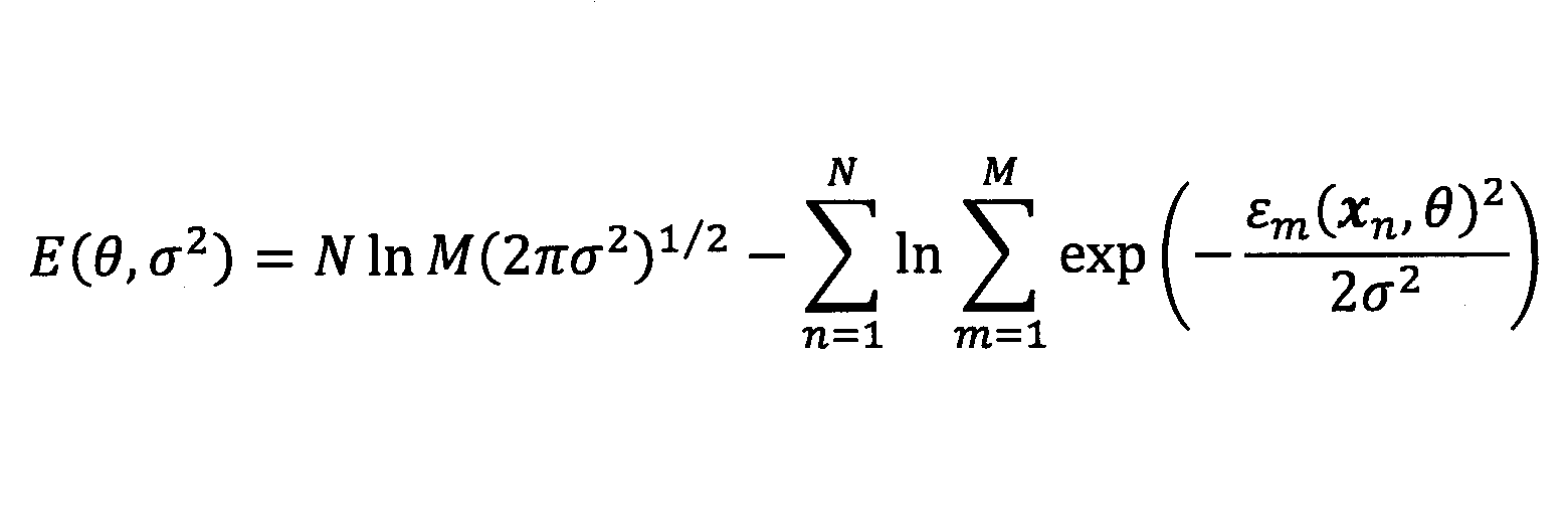
数2は、混合ガウスモデルの対数尤度関数であるため、EMアルゴリズム等を用いることができる。本実施例では、EMアルゴリズム部124は、EMアルゴリズムに基づいて、対数尤度関数を最大化するパラメータθ及び分散σ2を導出する。
部位mに係る幾何モデルが円柱であるとき、表面残差εm(xn,θ)は、次の通り表現できる。尚、ベクトル間の符号"×"は外積を表す。
εm(xn,θ)=|(xn-em 0)×em 0|-rm
但し、本実施例では、線形化のため、表面残差εm(xn,θ)は、数2の中での指数部分が二乗の差となるように表現され、具体的には以下のとおりである。
εm(xn,θ)=|(xn-em 0)×em 0|-rm
但し、本実施例では、線形化のため、表面残差εm(xn,θ)は、数2の中での指数部分が二乗の差となるように表現され、具体的には以下のとおりである。
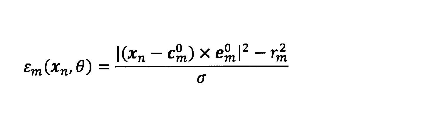
Eステップでは、EMアルゴリズム部124は、以下の事後分布pnmを計算する。
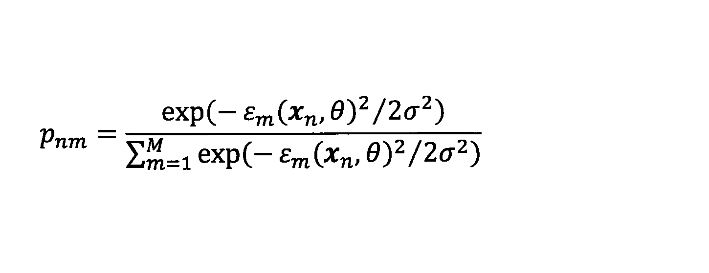
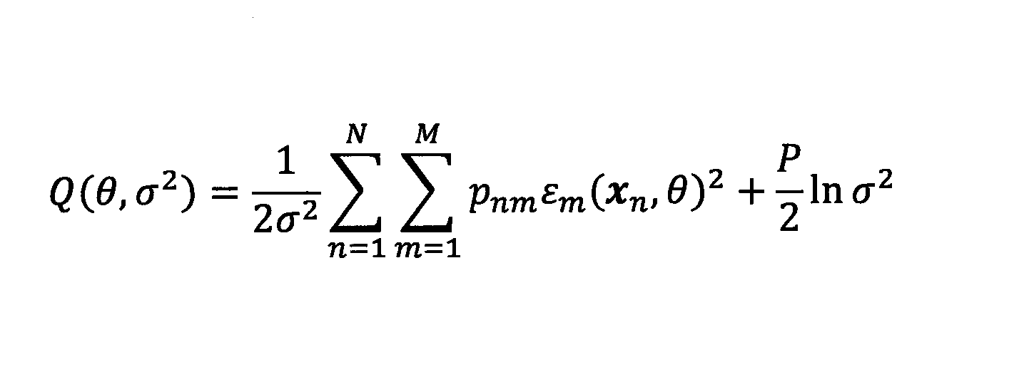

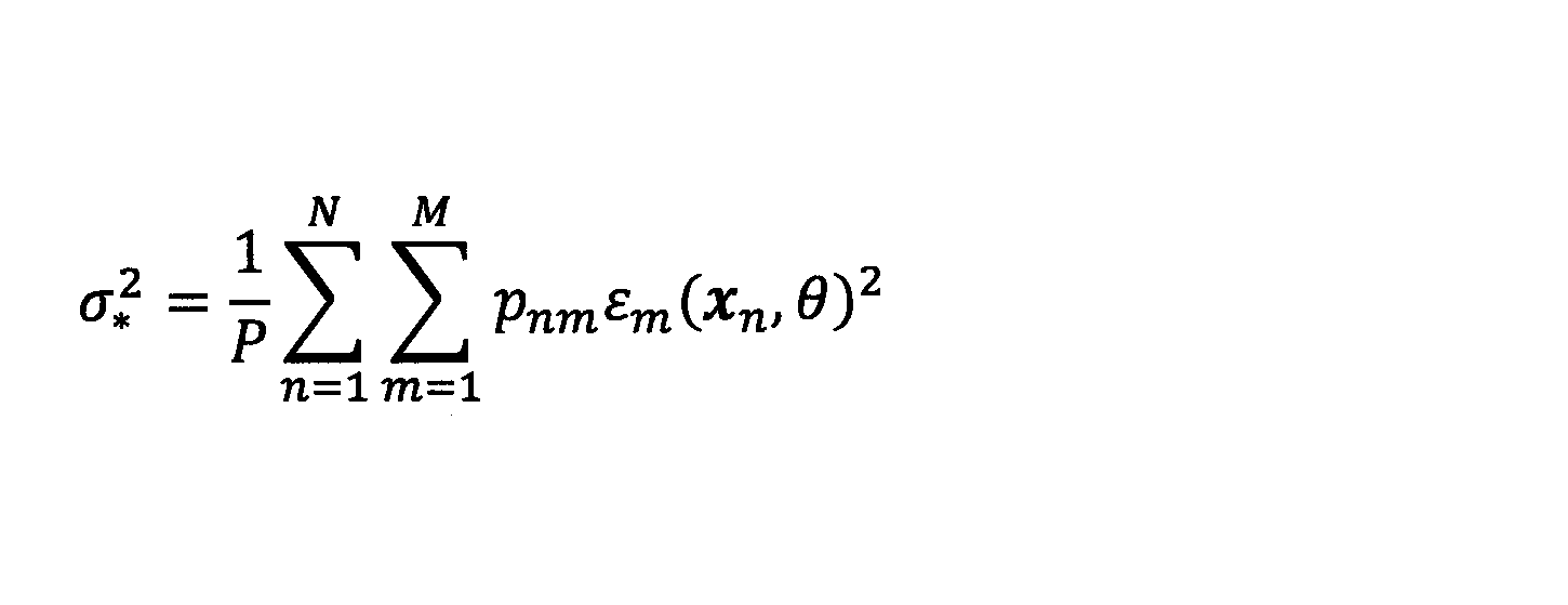

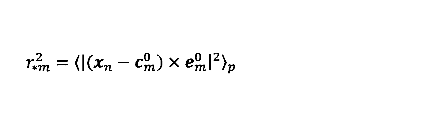


或いは、期待値Q(θ,σ2)は、パラメータθの各要素(rm、cm 0、及びem 0)に関して非線形であるので、向きem 0は、線形近似により導出されてもよい。具体的には、微小回転による更新式は、ノルムが保存される態様で規定され、以下のとおりである。


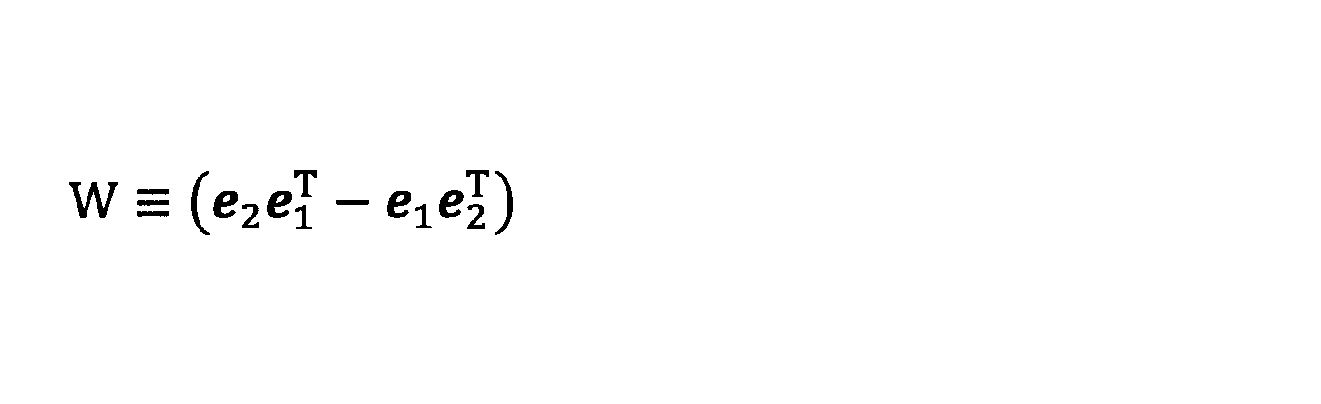
また、数13におけるanmやbnmは、以下のとおりである(図4に示した関節a0~a15や骨格b1~b15の表記とは無関係である)。


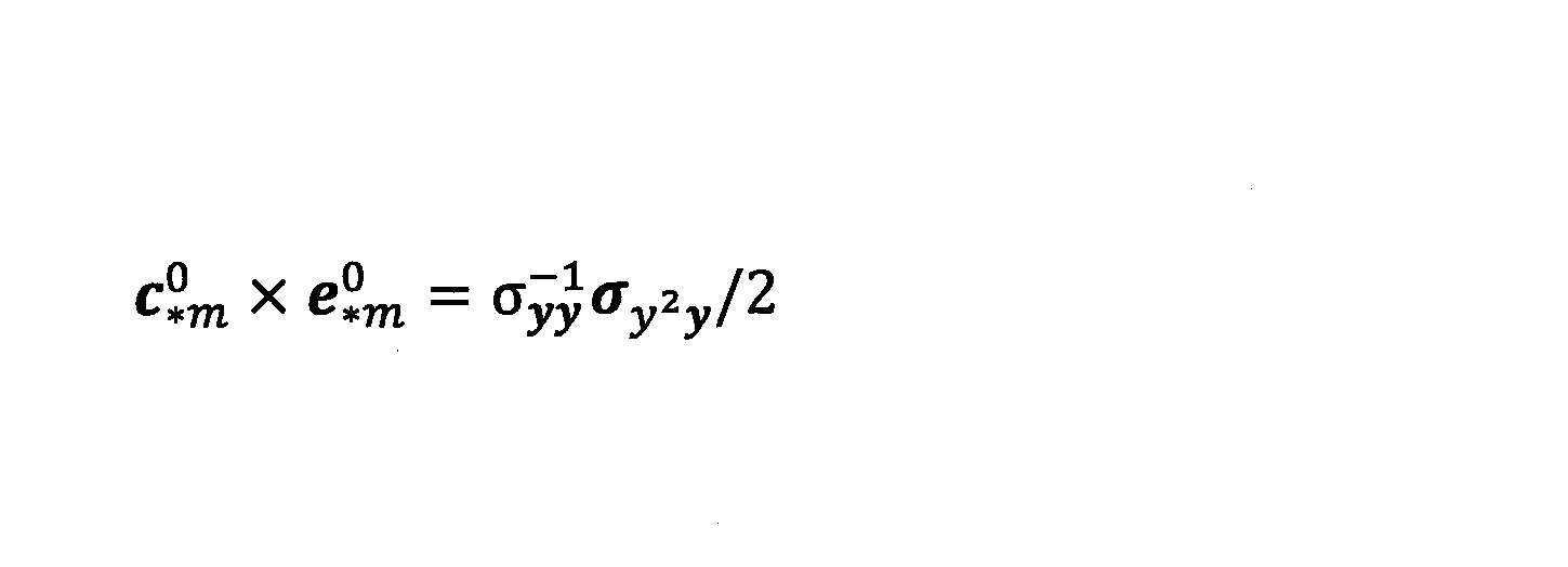
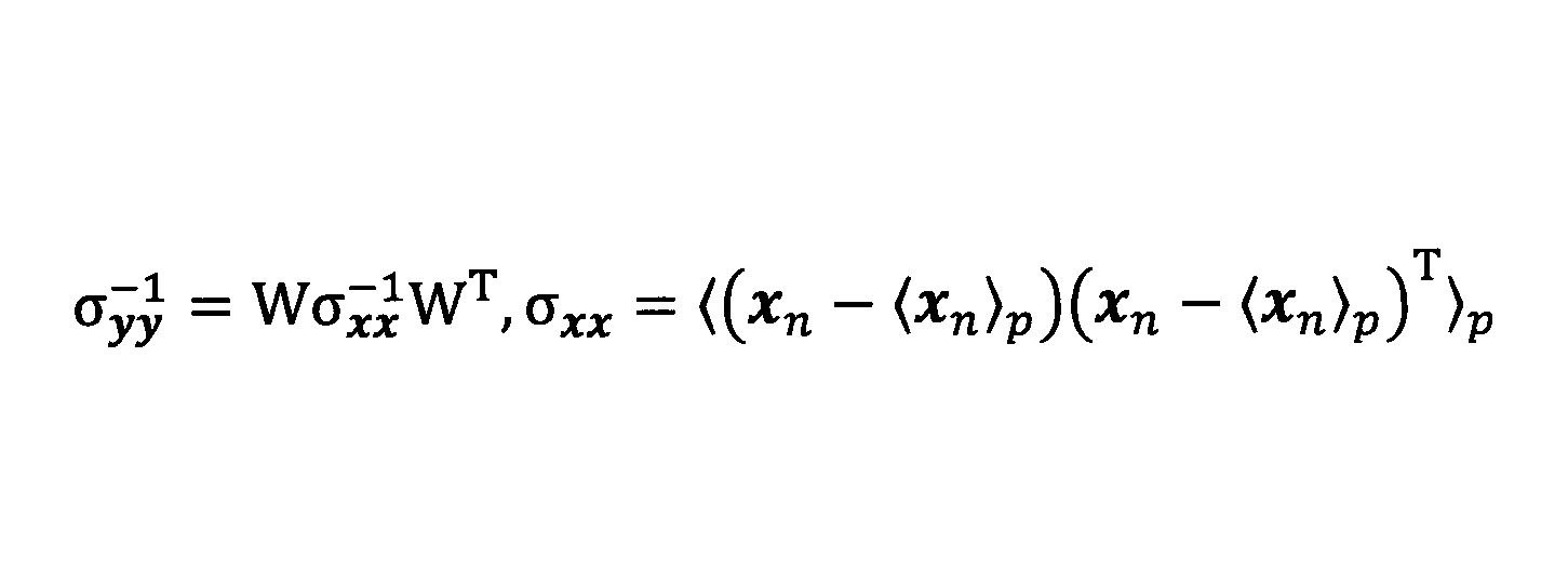

尚、変形例では、例えば他の計測によって対象者Sの形状情報を所持している場合などでは、パラメータθのうちの太さrmは、ユーザにより手入力されてもよいし、形状情報に基づいて自動的に設定されてもよい。この場合、EMアルゴリズム部124は、パラメータθのうちの残りの要素(位置cm
0及び向きem
0)を導出することになる。尚、他の計測は、事前の精密な計測であってもよいし、並行して実行されるものであってもよい。
モデル最適化部126は、EMアルゴリズム部124が一の部位に対して複数種類の幾何モデルを用いてフィッティングを実行する際、実行した複数種類のうちの、フィッティングの際のあてはまりが最も良好な種類の幾何モデルを導出する。
複数種類の幾何モデルは、円柱以外の幾何モデルとして、円錐、台形柱、楕円柱、楕円錐、及び台形楕円柱のうちの少なくともいずれか1つに係る幾何モデルを含む。但し、一の部位に係る複数種類の幾何モデルは、円柱を含まなくてもよい。また、一の部位に係る複数種類の幾何モデルは、部位ごとに異なってもよい。また、一部の特定の部位については、複数種類の幾何モデルを用いずに、単一の固定の幾何モデルが使用されてもよい。
例えば、EMアルゴリズム部124は、まず、円柱の幾何モデルを用いて、各部位に対するフィッテングを行う。次いで、EMアルゴリズム部124は、ある部位に係る幾何モデルを、円柱から他(例えば円錐等)に切り替え、同部位に対するフィッテングを行う。そして、モデル最適化部126は、対数尤度関数の最も大きな幾何モデルを、あてはまりが最も良好な種類の幾何モデルとして選択する。モデル最適化部126は、対数尤度関数の最も大きな幾何モデルに代えて、事後分布のデータ和の全部位和が最も大きな幾何モデルを、あてはまりが最も良好な種類の幾何モデルとして選択してもよい。
円錐の場合、表面残差εm(xn,θ)は、以下の通り表現されてよい。

台形柱の場合、表面残差εm(xn,θ)は、円錐の場合と同様であってよい。即ち台形柱の場合、円錐の一部に対して分布を規定することで表現できる。
楕円柱の場合、表面残差εm(xn,θ)は、以下の通り表現されてよい。
また、楕円錐の場合、表面残差εm(xn,θ)は、以下の通り表現されてよい。

また、台形柱と円錐との関係と同様、台形楕円柱の場合、表面残差εm(xn,θ)は、楕円錐の場合と同様であってよい。
ここで、長さが無限として定式化されている円柱や楕円柱などの幾何モデルを用いる場合、Eステップでは、EMアルゴリズム部124は、好ましくは、有限長処理を行う。有限長処理は、点群データxnのうちの、所定の条件を満たすデータについてのみ事後分布pnmを算出し、他のデータについては事後分布pnmを0とする処理である。有限長処理は、部位mに無関係なデータの混入を防ぐための処理であり、所定の条件は、部位mに無関係なデータを排除できるように設定される。これにより、実際には関係ないはずの点群データが解析に影響を及ぼすことを抑制できる。所定の条件を満たすデータは、例えば、以下の式を満たすデータであってよい。

長さ算出部128は、長さが無限として定式化されている円柱や楕円柱などの幾何モデルがEMアルゴリズム部124によって利用された場合に、幾何モデルの中心から端部までの長さ(部位mの中心から端部までの長さ)に対応する長さパラメータlmを導出する。例えば、長さ算出部128は、部位mの長さパラメータlmを、分散共分散行列σxxを用いて以下の通り算出してもよい。
或いは、長さ算出部128は、部位mの軸方向に沿った点群データの分布態様に基づいて、部位mの長さパラメータlmを導出してもよい。具体的には、長さ算出部128は、部位mの長さパラメータlmを、半値全幅による決定によって算出してもよい。半値全幅とはデータが多いところと比べて、データ数が半分になるところまでの区間を指す。長さ算出部128は、部位mの「切れ目」を見つけることで長さパラメータを導出する。即ち、長さ算出部128は、部位mを、向きem
0に係る軸方向を法線とする輪の態様で軸方向に沿って細かく輪切りにして、その中に含まれるデータ数をカウントし、所定の閾値以下になったところを「切れ目」と規定する。具体的には、半値全幅による決定では、所定の閾値は、カウント値の最大値の半分であるが、カウント値の最大値の0.1倍のような半分以外の値であってもよい。
ここで、図5及び図6を参照して、長さ算出部128による半値全幅による決定方法の一例を具体的に説明する。
図5は、EMアルゴリズム部124による導出結果(幾何モデルによるフィッティング結果)を模式的に示す図であり、図6は、長さ算出部128による半値全幅による決定方法の説明用の概略フローチャートである。
図5では、頭部及び胴部がそれぞれ1つずつの円柱でフィッテングされており、両腕部及び両脚部が、それぞれ片方ずつ、1つずつの円柱でフィッテングされている。図5では、対象者Sの腕部が部位mである場合について代表して、部位mの長さパラメータlm(l+
m及びl-
m)の算出方法について説明する。尚、図5に示すように、ここでは、腕部は、肘の関節が伸ばされているため、EMアルゴリズム部124により1つの部位として認識されている(1つの幾何モデルで当てはめられている)。
ステップS600では、長さ算出部128は、n=1に設定する。nの意義は後述する。
ステップS602では、長さ算出部128は、点群データxnのうちの、次の条件を満たすデータの数をカウントする。

ステップS604では、長さ算出部128は、ステップS602で得たカウント数に基づいて、基準値Crefを設定する。例えば、長さ算出部128は、ステップS602で得たカウント数を、基準値Crefとして設定する。
ステップS606では、nを"1"だけインクリメントする。
ステップS608では、長さ算出部128は、点群データxnのうちの、次の条件を満たすデータの数をカウントする。即ち、長さ算出部128は、Δlmだけずらした次の区間において、次の条件を満たすデータの数をカウントする。
ステップS612では、長さ算出部128は、現在のnの値を用いて、部位mのうちの、中心から子孫側の端部までの長さパラメータl+
mを、nΔlmとして算出する。即ち、l+
m=nΔlmとして算出する。
ステップS620~ステップS632では、長さ算出部128は、逆方向(祖先側)に進むことで、同様の考えた方で、図5に示す部位mのうちの、中心から祖先側の端部までの長さパラメータl-
mを算出する。
尚、変形例として、長さ算出部128は、次の通り、部位mの長さパラメータlmを算出してもよい。


部位認識部130は、部位mのパラメータ(rm、cm
0、及びem
0)の導出結果と、部位mの長さパラメータlmの導出結果とに基づいて、部位認識処理を行う。部位認識処理は、部位mと対象者Sの各部位(図4の各部位b1~b15参照)との対応関係を認識することを含む。
ここで、部位mの長さパラメータlmの導出結果及びcm
0及びem
0の導出結果によれば、部位mの中心(=〈xn・em
0〉p)からの長さパラメータl+
m、l-
mに基づいて、部位mの軸上の端部(長さパラメータlmを決める端部)の位置を導出できる。具体的には、部位mの軸上の端部の位置ξm
0は、以下を満たす。
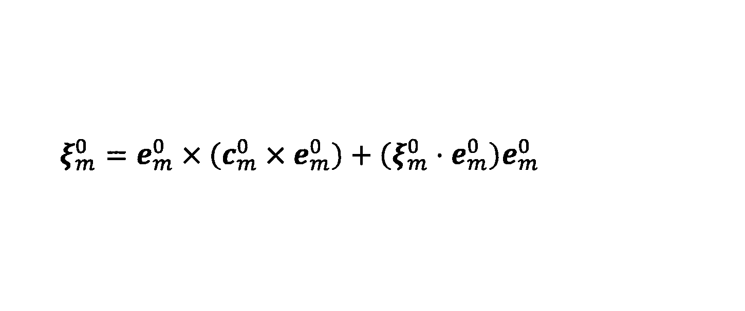
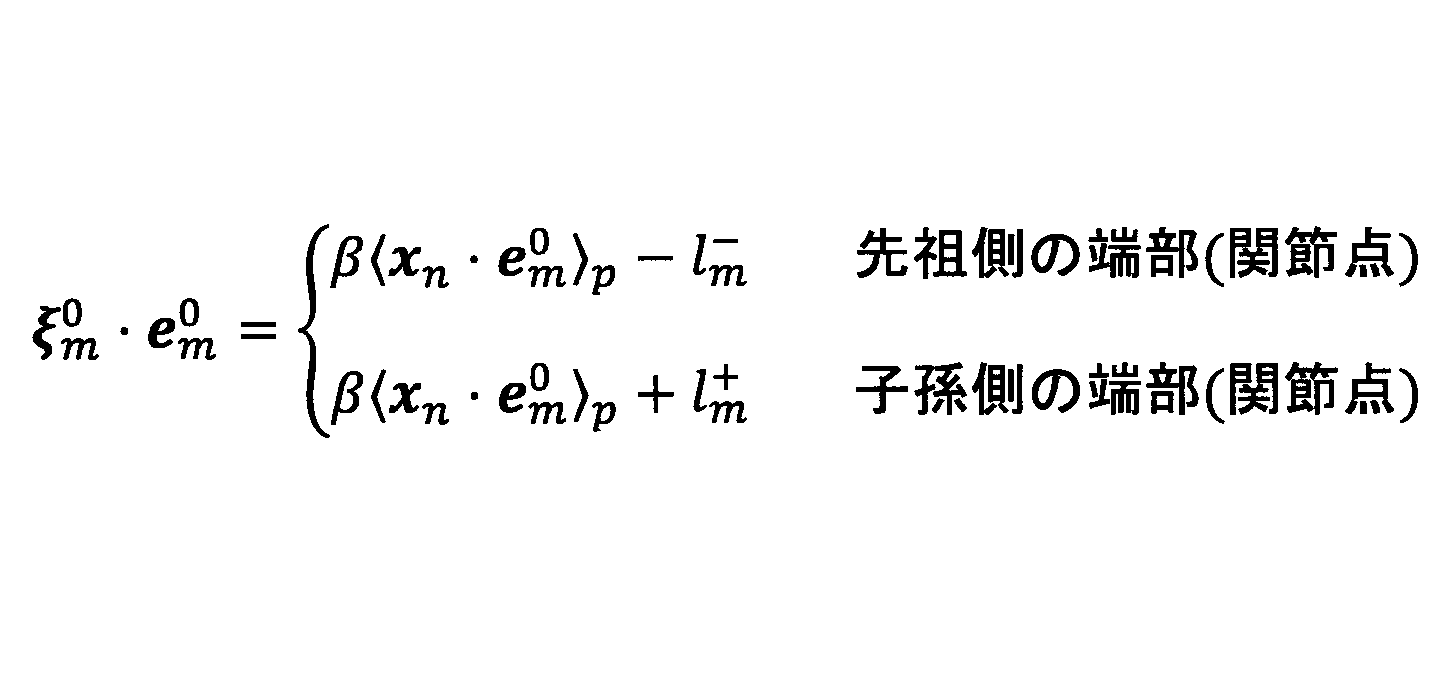
以下の説明で、「関節点」とは、関節に係る代表点(関節に係る位置を表す点)を指し、このようにして導出できる部位mの端部(位置)も関節点に対応する。また、以下の説明で、部位m*(*は、任意の記号)は、パラメータ(rm、cm
0、及びem
0)が得られた部位m(m=1,2、・・・、M)のうちの特定の部位を表す。部位認識部130は、太さrmを利用して、主部位を識別する。主部位は、太さが最も大きい部位であり、本実施例では、対象者Sの胴部である。
部位認識部130は、最も太い部位、又は、太さの差が所定値未満でありかつ隣接する2つの1番目と2番目に太い部位を、対象物の主部位として認識する。具体的には、部位認識部130は、1番目に大きい部位m1と2番目に大きい部位m2との間の差が所定値未満である場合は、部位認識部130は、いずれの部位m1、m2も胴部として識別する。所定値は、部位m1、m2の太さの差に対応した適合値である。他方、1番目に大きい部位m1と2番目に大きい部位m2との間の差が所定値以上である場合は、部位認識部130は、1番目に大きい部位m1だけを、胴部(部位b1+部位b2)として識別する。この場合、部位認識部130は、部位mlに対して、「切断フラグ」を設定する。切断フラグの意義は後述する。これにより、例えば、図4において、対象者Sの姿勢に応じて、部位b1及び部位b2が真っ直ぐ伸びている場合でも、部位b1及び部位b2を、部位m1及び部位m2に係る胴部として認識できる。
部位認識部130は、主部位(胴部)を識別すると、胴部の底面近傍にある関節点を判定(識別)する。胴部の底面に対しては、部位認識部130は、胴部の底面側の端部の位置に設定される微小な円柱(あるいは楕円柱や台形柱など)内に、胴部側の端部の位置が属する2つの部位ml,mrを特定する。尚、微小な円柱の高さは所定の値が使用されてもよい。そして、部位認識部130は、部位ml,mrを、左脚部に係る部位(図4の部位b10又は、部位b10+b11参照)と右脚部に係る部位(図4の部位b12又は、部位b12+b13参照)として認識する。
部位認識部130は、左脚部に係る部位mlを識別すると、部位mlにおける胴部から遠い側の端部の位置に設定される球(以下、「連結球」とも称する)内に、胴部に近い側の端部の位置を有する部位が存在するか否かを判定する。尚、連結球の径は所定の値が使用されてもよい。そして、連結球内に、胴部に近い側の端部の位置を有する部位ml2が存在する場合は、部位認識部130は、部位mlを、左脚部の腿b10として認識し、部位ml2を、左脚部の脛b11として認識する。他方、連結球内に、胴部に近い側の端部の位置を有する部位が存在しない場合は、部位認識部130は、部位mlを、左脚部の腿と脛の双方を含む部位として認識する。この場合、部位認識部130は、部位mlに対して、「切断フラグ」を設定する。これにより、例えば、図4において、対象者Sの姿勢に応じて、部位b10及びb11が真っ直ぐ伸びている場合でも、部位b10及びb11を、左脚部に係る部位として認識できる。
同様に、部位認識部130は、右脚部に係る部位mrを識別すると、部位mrにおける胴部から遠い側の端部の位置に設定される球(連結球)内に、胴部に近い側の端部の位置を有する部位が存在するか否かを判定する。尚、連結球の径は所定の値が使用されてもよい。そして、連結球内に、胴部に近い側の端部の位置を有する部位mr2が存在する場合は、部位認識部130は、部位mrを、右脚部の腿b12として認識し、部位mr2を、右脚部の脛b13として認識する。他方、連結球内に、胴部に近い側の端部の位置を有する部位が存在しない場合は、部位認識部130は、部位mrを、右脚部の腿と脛の双方を含む部位として認識する。この場合、部位認識部130は、部位mrに対して、「切断フラグ」を設定する。これにより、例えば、図4において、対象者Sの姿勢に応じて、部位b12及びb13が真っ直ぐ伸びている場合でも、部位b12及びb13を、右脚部に係る部位として認識できる。
また、部位認識部130は、主部位(胴部)を識別すると、胴部の側面近傍にある関節点を判定(識別)する。部位認識部130は、胴部の軸方向(主軸)の側面にあり、かつ頭部側の面から最も近い2関節点を左右の腕部の根本の関節点(肩の関節に係る関節点)として識別する。例えば、部位認識部130は、胴部の側面における薄いトーラス(円柱に係るトーラス)内に含まれる関節点を、腕部の根本の関節点として識別する。尚、トーラスの厚さなどは所定の値が使用されてもよい。そして、部位認識部130は、左右の腕部の根本の関節点を含む部位mlh,mrhを、左手に係る部位(図4の部位b5又は、部位b5+b6参照)と右手に係る部位(図4の部位b8又は、部位b8+b9参照)として認識する。
部位認識部130は、左手に係る部位mlhを識別すると、部位mlhにおける胴部から遠い側の端部の位置に設定される球(連結球)内に、胴部に近い側の端部の位置を有する部位が存在するか否かを判定する。なお、連結球の径は所定の値が使用されてもよい。そして、連結球内に、胴部に近い側の端部の位置を有する部位mlh2が存在する場合は、部位認識部130は、部位mlhを、左手の上腕部b5として認識し、部位mlh2を、左手の前腕部b6として認識する。他方、連結球内に、胴部に近い側の端部の位置を有する部位が存在しない場合は、部位認識部130は、部位mlhを、左手の上腕部と前腕部の双方を含む部位として認識する。この場合、部位認識部130は、部位mlhに対して、「切断フラグ」を設定する。これにより、例えば、図4において、対象者Sの姿勢に応じて、部位b5及びb6が真っ直ぐ伸びている場合でも、部位b5及びb6を、左手に係る部位として認識できる。
同様に、部位認識部130は、右手に係る部位mrhを識別すると、部位mrhにおける胴部から遠い側の端部の位置に設定される球(連結球)内に、胴部に近い側の端部の位置を有する部位が存在するか否かを判定する。なお、連結球の径は所定の値が使用されてもよい。そして、連結球内に、胴部に近い側の端部の位置を有する部位mrh2が存在する場合は、部位認識部130は、部位mrhを、右手の上腕部b8として認識し、部位mrh2を、右手の前腕部b9として認識する。他方、連結球内に、胴部に近い側の端部の位置を有する部位が存在しない場合は、部位認識部130は、部位mrhを、右手の上腕部と前腕部の双方を含む部位として認識する。この場合、部位認識部130は、部位mrhに対して、「切断フラグ」を設定する。これにより、例えば、図4において、対象者Sの姿勢に応じて、部位b8及びb9が真っ直ぐ伸びている場合でも、部位b8及びb9を、右手に係る部位として認識できる。
骨格整形部132は、骨格整形処理として、切断処理、結合処理、及び連結処理を行う。
切断処理は、一の部位を、2つの更なる部位に分離する処理である。分離対象の部位は、部位mのうちの、上述の切断フラグが設定された部位である。尚、切断処理の対象となる部位に係る幾何モデル(即ち上述の切断フラグが設定された部位に係る幾何モデル)は、第1幾何モデルの一例である。切断フラグが設定された部位は、例えば上腕部と前腕部(図4の部位b5及びb6参照)のような、真っ直ぐ伸ばした状態であるときに幾何モデルによる当てはめで一の部位として認識された部位である。切断処理は、このような本来2部位からなる部位を、2つの更なる部位に分離する。パラメータθの各要素(rm、cm
0、及びem
0)のうち、2つの更なる部位のrm及びem
0は、そのままである。他方、骨格整形部132は、2つの更なる部位のcm
0の間の関節の位置(即ち、切断フラグが設定された部位の中間の関節点)を、数32に従って求める。中間の関節点の場合は、数32の右辺第2項は、以下の通りである。尚、中間の関節点の導出には、cm
0及びem
0の導出結果が用いられる。

このようにして切断処理によれば、部位mが、本来2部位からなる部位を含む場合でも、2つの更なる部位に切断して、3つの関節点を導出できる。従って、例えば脚部が伸ばされて肘や膝が真っ直ぐ伸びている場合でも、切断処理によって3つの関節点を導出できる。
結合処理は、隠れた骨格で繋がる2つの部位mの位置cm
0、向きem
0、及び長さパラメータlmに基づいて、2つの部位mにわたる直線に対応付けれる対象者Sの隠れた骨格を導出する処理である。具体的には、結合処理は、隠れた骨格を、所定の2つの部位mに係る2関節点間を結ぶ直線として生成する処理である。尚、結合処理の対象となる所定の2つの部位mに係る幾何モデルは、第2幾何モデルの一例である。隠れた骨格とは、図4を参照して上述したように、股関節に係る骨格b14、b15や、肩の関節に係る骨格b4、b7がある。股関節に係る骨格b14については、結合処理の対象となる2関節点は、部位b1の底面側の関節点a0と、部位b10の胴部側の関節点a14とが対応する。また、股関節に係る骨格b15については、所定の2関節は、部位b1の底面側の関節点a0と、部位b12の胴部側の関節点a15とが対応する。肩の関節に係る骨格b4については、所定の2関節は、部位b2の頭部側の関節点a2と、部位b5の胴部側の関節点a4とが対応する。肩の関節に係る骨格b7については、所定の2関節は、部位b2の頭部側の関節点a2と、部位b8の胴部側の関節点a7とが対応する。
このようにして結合処理によれば、関節モデルが隠れた骨格を含む場合でも、結合処理により隠れた骨格(リンクに対応する直線)を導出できる。尚、隠れた骨格に係る直線の方向は、隠れた骨格に係る部位sの向きes
0として利用されてもよいし、直線上の位置は、隠れた骨格に係る部位sの位置cs
0として利用されてもよい。
連結処理は、異なる部位に係る幾何モデルから導出できる同じ関節に係る関節点(共通の関節点)を、1つの関節点に統合(連結)する処理である。例えば、連結対象の関節点は、例えば上述した連結球内の2つの関節点(図4の関節a5、a8、a10、a12に係る関節点)である。このような腕部及び脚部に係る連結処理は、切断フラグが設定されない場合に実行される。また、他の連結対象の関節点は、首の関節点に係り、頭部の幾何モデルと胴部の幾何モデルの両方から得られる2つの関節点(図4の関節a2に係る関節点)である。また、他の連結対象の関節点は、太さrmが1番目に大きい部位m1と2番目に大きい部位m2とをそれぞれ胴部として識別した場合において、部位m1と部位m2との間の関節点(図4の関節a1に係る関節点)である。即ち、胴部に係る連結処理は、切断フラグが設定されない場合に実行される。
連結処理は、単にいずれか一方の関節点を選択する処理であってもよい。或いは、2つの関節点の平均値を利用する方法や、2つの関節点に係る2つの部位のうち、事後分布のデータ和が大きい方の部位の値を利用する方法、事後分布のデータ和で重み付けした値を利用する方法などであってもよい。
骨格整形部132は、骨格整形処理として、好ましくは、更に、対称化処理を行う。対称化処理は、本来実質的に左右対称な部位に対して、パラメータについても左右対称に補正する処理である。本来実質的に左右対称な部位は、例えば左右の腕部や、左右の脚部である。例えば左右の腕部(左右の脚部についても同様)について、骨格整形部132は、パラメータθのうちの太さrmと、長さパラメータlmについて、事後分布のデータ和の最も大きい方に統一してよい。例えば左脚部に係る事後分布のデータ和が右脚部に係る事後分布のデータ和よりも大きい場合、左脚部に係る太さrmと長さパラメータlmに、右脚部に係る太さrmと長さパラメータlmを補正する。これにより、左右の対称性を利用して、太さrmや長さパラメータlmの精度を高めることができる。
出力部134は、表示装置等(図示せず)に、対象者Sの骨格情報(図3では、"認識結果"と表記)を出力する。例えば、出力部160は、フレーム周期ごとに、略リアルタイムに、対象者Sの骨格情報を出力してもよい。或いは、対象者Sの動きの解説用などでは、出力部160は、非リアルタイムで、骨格情報を時系列に出力してもよい。骨格情報は、関節a0~a15の各位置を特定できる情報を含んでもよい。また、骨格情報は、骨格b1~b15の位置や、向き、太さを特定できる情報を含んでもよい。骨格情報の用途は任意であるが、次のフレーム周期における同骨格情報の導出に利用されてもよい。また、骨格情報は、最終的には、体操等の競技時の対象者Sの動きの解析に利用されてもよい。例えば体操の競技時の対象者Sの動きの解析では、骨格情報に基づく技の認識や技の定量化(得点など)が実現されてもよい。また、他の用途としては、作業者を想定する対象者Sの動きを解析して、ロボットプログラムに利用されてもよい。或いは、ジェスチャーによるユーザインターフェースや、個人の識別、熟練技術の定量化などに利用することもできる。
本実施例によれば、上述のように、幾何モデルを用いてフィッテングを行って得られる結果に対して、切断処理が実行される。これにより、例えば対象者Sの胴部や腕部、脚部のような、関節で繋がる2つの部位が真っ直ぐに伸ばされている場合でも、該2つの部位を繋ぐ関節を精度良く認識できる。即ち、幾何モデルを用いたフィッテングだけでは一部位としてしか認識できないような状況下(本来は2つの部位が一部位としてしか認識できないような状況下)でも、2つの部位を繋ぐ関節を精度良く認識できる。また、本実施例によれば、上述のように、幾何モデルを用いてフィッテングを行って得られる結果に対して、結合処理が実行される。これにより、幾何モデルを用いたフィッテングだけでは精度良く認識し難い隠れた骨格についても精度良く認識できる。このようにして、本実施例によれば、対象者Sの点群データに基づいて、対象者Sの関節又は骨格を精度良く認識できる。
次に、図7以降の概略フローチャートを参照して、本実施例による対象物認識システム1の動作例について説明する。
図7は、対象物認識システム1の全体動作の一例を示す概略フローチャートであり、図8は、部位認識処理の一例を示す概略フローチャートである。図9A及び図9Bは、図7の処理等の説明図である。図9A及び図9Bには、ある一時点(一シーン)に係る点群データxnがそれぞれ示されている。
ステップS700では、データ入力部120に、ある一時点に係る点群データxnが入力される。
ステップS702では、クラスタリング部122は、ステップS700で得た点群データxnに基づいて、幾何モデルを用いたフィッティングに用いる初期値を取得する。クラスタリング部122の処理(初期値の取得方法)の詳細は上述のとおりである。
ステップS704では、EMアルゴリズム部124は、ステップS700で得た点群データxnと、ステップS702で得た初期値とに基づいて、EMアルゴリズムのEステップを実行する。EMアルゴリズムのEステップの詳細は上述のとおりである。
ステップS705では、EMアルゴリズム部124は、j=1に設定する。
ステップS706では、EMアルゴリズム部124は、j番目の部位j(m=j)について有限長処理を行う。有限長処理の詳細は上述のとおりである。
ステップS708では、EMアルゴリズム部124は、ステップS704で得たEステップの結果と、ステップS706で得た有限長処理結果とに基づいて、j番目の部位j(m=j)についてEMアルゴリズムのMステップを実行する。EMアルゴリズムのMステップの詳細は上述のとおりである。
ステップS710では、EMアルゴリズム部124は、未処理部位が有るか否か、即ちj<Mであるか否かを判定する。未処理部位が有る場合は、ステップS711を経て、ステップS706からの処理を繰り返す。未処理部位が無い場合は、ステップS712に進む。
ステップS711では、EMアルゴリズム部124は、jを"1"だけインクリメントする。
ステップS712では、EMアルゴリズム部124は、収束したか否かを判定する。収束条件としては、例えば、対数尤度関数が所定の値以下であることや、対数尤度関数の移動平均が所定の値以下であることなどが使用されてもよい。
ステップS714では、モデル最適化部126は、モデル最適化処理を行う。例えば、モデル最適化部126は、今回の使用した幾何モデルに係る事後分布のデータ和の全部位和を算出する。そして、事後分布のデータ和の全部位和が所定基準値未満である場合は、EMアルゴリズム部124に幾何モデルの変更を指示して、ステップS704からステップS712の処理を再度実行させる。或いは、モデル最適化部126は、今回の使用した幾何モデルに係る事後分布のデータ和の全部位和の如何にかかわらず、EMアルゴリズム部124に幾何モデルの変更を指示して、ステップS704からステップS712の処理を再度実行させる。この場合、モデル最適化部126は、事後分布のデータ和の全部位和が最も大きな幾何モデルを、あてはまりが最も良好な種類の幾何モデルとして選択する。
ステップS714までの処理が終了すると、図9Aに示すように、点群データxnに対して当てはめられた複数の幾何モデルに係るパラメータθ(rm、cm
0、及びem
0)が得られる。図9Aに示す例では、点群データxnに対して当てはめられた6つの幾何モデルM1~M6が概念的に示される。幾何モデルM1は、対象者Sの頭部に係る幾何モデルであり、幾何モデルM2は、対象者Sの胴部に係る幾何モデルであり、幾何モデルM3及びM4は、対象者Sの両腕部に係る幾何モデルであり、幾何モデルM5及びM6は、対象者Sの両脚部に係る幾何モデルである。図9Aに示す例では、幾何モデルM1~M6は、全て円柱である。
ステップS716では、長さ算出部128は、点群データxnと、ステップS714までの処理で得られるパラメータθとに基づいて、各幾何モデル(幾何モデルM1~M6参照)の長さパラメータlmを導出する。長さパラメータlmを導出することは、上述のように、部位mの中心に対して、長さパラメータl+
m及び長さパラメータl-
mを導出することを含む。
ステップS718では、部位認識部130は、部位認識処理を行う。部位認識処理は、上述のとおりであるが、一例の手順については、図8を参照して後述する。
ステップS720では、骨格整形部132は、ステップS718で得た部位認識処理結果等に基づいて、切断処理、結合処理、及び連結処理を行う。骨格整形部132は、切断フラグが設定された部位については切断処理を行う。切断処理の詳細は上述のとおりである。また、結合処理は、上述のとおりであり、股関節に係る骨格b14、b15や、肩の関節に係る骨格b4、b7に係る各直線を導出することを含む。また、連結処理の詳細は上述のとおりである。
ステップS720までの処理が終了すると、図9Bに概念的に示すように、切断処理に係る各関節の位置や、隠れた骨格等が導出される。
ステップS722では、骨格整形部132は、ステップS704~ステップS712で得られる事後分布のデータ和に基づいて、対称化処理を行う。対称化処理の詳細は上述のとおりである。
続いて、ステップS718における部位認識処理を図8を参照して説明する。
ステップS800では、部位認識部130は、太さrmについて、1番目と2番目に太い部位の差が所定値以上であるか否かを判定する。判定結果が"YES"の場合は、ステップS802に進み、それ以外の場合は、ステップS804に進む。
ステップS802では、部位認識部130は、太さrmが1番目に大きい部位m1を胴部(真っ直ぐ伸びた胴部)として識別し、部位m1に対して切断フラグを設定する。例えば、図9Aに示す例では、幾何モデルM2が対応付けられる部位は、2番目に太い部位との差が所定値以上である1番目に太い部位m1となり、切断フラグが設定されることになる。尚、このようにして部位m1に切断フラグが設定されると、図7のステップS720にて部位m1に対して切断処理が実行されることになる。
ステップS804では、部位認識部130は、太さrmが1番目に大きい部位m1と2番目に大きい部位m2とを、胴部として識別する。
ステップS806では、部位認識部130は、頭部を認識する。例えば、部位認識部130は、部位m1の上面近傍の部位mhを、頭部として認識する。例えば図9Aに示す例では、幾何モデルM1が対応付けられる部位が頭部として認識されることになる。
ステップS808では、部位認識部130は、胴部の底面近傍に左右の脚部を認識する。即ち、部位認識部130は、上述のように、胴部の底面近傍に左右の2関節点を各脚部の根本の関節点として識別し、該2関節点を有する部位ml,mrを、左右の脚部に係る部位と認識する。
ステップS810では、部位認識部130は、ステップS808で認識した左右の脚部に係る部位ml,mrの末端側(胴部から遠い側)に、他の部位ml2,mr2に係る関節点が存在するか否かを判定する。この際、部位認識部130は、左右の脚部についてそれぞれ別に判定する。判定結果が"YES"の場合は、ステップS812に進み、それ以外の場合は、ステップS814に進む。
ステップS812では、部位認識部130は、ステップS808で認識した左右の脚部に係る部位ml,mrを、腿部として認識するとともに、ステップS810で認識した他の部位ml2,mr2を、脛部として認識する。尚、この場合、図7のステップS720にて、部位ml,ml2に対して連結処理が実行され、部位mr,mr2に対して連結処理が実行されることになる。
ステップS814では、部位認識部130は、ステップS808で認識した左右の脚部に係る部位ml,mrを、真っ直ぐ伸びた脚部であると認識し、部位ml,mrに対して切断フラグを設定する。尚、このようにして部位ml,mrに切断フラグが設定されると、図7のステップS720にて部位ml,mrに対してそれぞれ切断処理が実行されることになる。
ステップS816では、部位認識部130は、胴部の上側(脚部から遠い側)の左右の側面に左右の腕部を認識する。即ち、部位認識部130は、上述のように、胴部の側面における薄いトーラス内に含まれる2関節点を各腕部の根本の関節点として識別し、該2関節点を有する部位mlh,mrhを、左右の腕部に係る部位と認識する。
ステップS818では、部位認識部130は、ステップS808で認識した左右の腕部に係る部位mlh,mrhの末端側(胴部から遠い側)に、他の部位mlh2,mrh2に係る関節点が存在するか否かを判定する。この際、部位認識部130は、左右の腕部についてそれぞれ別に判定する。判定結果が"YES"の場合は、ステップS820に進み、それ以外の場合は、ステップS822に進む。
ステップS820では、部位認識部130は、ステップS816で認識した左右の腕部に係る部位mlh,mrhを上腕部として認識するとともに、ステップS818で認識した他の部位mlh2,mrh2を、前腕部として認識する。尚、この場合、図7のステップS720にて、部位mlh,mlh2に対して連結処理が実行され、部位mrh,mrh2に対して連結処理が実行されることになる。
ステップS822では、部位認識部130は、ステップS816で認識した左右の腕部に係る部位mlh,mrhを、真っ直ぐ伸びた腕部であると認識し、部位mlh,mrhに対して切断フラグを設定する。尚、このようにして部位mlh,mrhに切断フラグが設定されると、図7のステップS720にて部位mlh,mrhに対してそれぞれ切断処理が実行されることになる。
図7及び図8に示す処理によれば、ある一時点(一シーン)に係る対象者Sの点群データxnに基づいて、対象者Sの関節又は骨格を精度良く認識することが可能となる。尚、図7及び図8に示す処理は、フレーム周期ごとに繰り返し実行されてもよいし、次のフレームに対しては、前回のフレームで得たパラメータθ及び分散σ2や前回のフレームで用いた幾何モデルを利用して、次のフレームに係るパラメータθ等が導出されてもよい。
以上、各実施例について詳述したが、特定の実施例に限定されるものではなく、特許請求の範囲に記載された範囲内において、種々の変形及び変更が可能である。また、前述した実施例の構成要素を全部又は複数を組み合わせることも可能である。
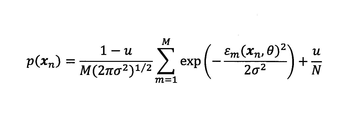
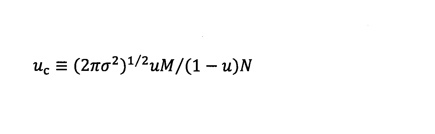
例えば、上述した実施例では、点群データxnがすべて幾何モデル表面近傍に存在するとして定式化してきたが、点群データxnにはノイズなども含まれる。そのような表面から離れたデータが混入すると、Eステップの事後分布が数値不安定となり正しく計算されない場合がある。そこで、分布p(xn)には、以下のように、ノイズ項として一様分布が追加されてもよい。

1 対象物認識システム
21 距離画像センサ
100 対象物認識装置
101 制御部
102 主記憶部
103 補助記憶部
104 ドライブ装置
105 記録媒体
107 入力部
120 データ入力部
122 クラスタリング部
124 EMアルゴリズム部
126 モデル最適化部
128 長さ算出部
130 部位認識部
132 骨格整形部
134 出力部
140 幾何モデルデータベース
21 距離画像センサ
100 対象物認識装置
101 制御部
102 主記憶部
103 補助記憶部
104 ドライブ装置
105 記録媒体
107 入力部
120 データ入力部
122 クラスタリング部
124 EMアルゴリズム部
126 モデル最適化部
128 長さ算出部
130 部位認識部
132 骨格整形部
134 出力部
140 幾何モデルデータベース
Claims (25)
- 3次元の位置情報を得るセンサから、複数の関節を有する対象物の表面に係る点群データを取得し、
前記点群データに、軸を有する幾何モデルを複数の個所で別々に当てはめ、前記点群データに当てはまる複数の幾何モデルのそれぞれの位置及び軸方向を導出する当てはめ処理を行い、
前記当てはめ処理の結果に基づいて、
前記点群データに当てはまる前記複数の幾何モデルのうちの、1つ以上の第1幾何モデルのそれぞれに対応付けられる前記対象物の3つの関節、及び、
前記点群データに当てはまる前記複数の幾何モデルのうちの、2つの第2幾何モデルにわたる前記対象物の骨格に対応付けられる前記対象物の2つの関節、
のうちの少なくともいずれか一方を認識することを含む、コンピュータにより実行される対象物認識方法。 - 前記第1幾何モデルの軸方向の中心から端部までの長さに対応する長さパラメータを導出することを更に含み、
前記第1幾何モデルに対応付けられる3つの関節を認識することは、前記第1幾何モデルの前記長さパラメータの導出結果に更に基づく、請求項1に記載の対象物認識方法。 - 前記第1幾何モデルに対応付けられる3つの関節を認識することは、前記第1幾何モデルの軸方向の中心に基づいて前記3つの関節のうちの中間の関節の位置を導出し、前記第1幾何モデルの軸上にありかつ前記第1幾何モデルの前記長さを決める両端部の各位置に基づいて前記3つの関節のうちの残りの2つの関節の位置を導出することを含む、請求項2に記載の対象物認識方法。
- 前記当てはめ処理は、事後分布の導出を伴う反復的な演算に基づき、
前記中間の関節の位置は、前記第1幾何モデルの軸方向の中心に対応し、
前記中間の関節の位置を導出することは、前記点群データの各点と前記第1幾何モデルの軸方向との内積に対して、事後分布を用いた平均操作を行うことを含む、請求項3に記載の対象物認識方法。 - 前記2つの第2幾何モデルの軸方向の中心から端部までの長さに対応する長さパラメータを導出することを更に含み、
前記骨格に対応付けられる2つの関節を認識することは、前記2つの第2幾何モデルの軸方向の前記長さパラメータの導出結果に更に基づく、請求項1に記載の対象物認識方法。 - 前記骨格に対応付けられる2つの関節を認識することは、前記2つの第2幾何モデルのそれぞれの軸上にありかつ前記長さを決める端部の位置に基づいて、前記2つの関節の位置を導出することを含む、請求項5に記載の対象物認識方法。
- 前記当てはめ処理は、事後分布の導出を伴う反復的な演算に基づき、
前記点群データに当てはまる前記複数の幾何モデルのそれぞれの軸方向の中心から端部までの長さに対応する長さパラメータを導出し、
前記点群データに当てはまる前記複数の幾何モデルのそれぞれについて、軸方向に垂直な方向の太さを導出又は取得し、
前記当てはめ処理の結果と、前記長さパラメータの導出結果と、前記太さの導出結果又は取得結果とに基づいて、前記点群データに当てはまる前記複数の幾何モデルと、前記対象物の各部位との対応関係を認識することを更に含む、請求項1に記載の対象物認識方法。 - 前記長さパラメータを導出することは、前記複数の幾何モデルのそれぞれごとに、前記当てはめ処理の結果と、前記点群データと、事後分布とに基づいて、幾何モデルの軸方向に沿った前記点群データの分布態様を評価することを含む、請求項7に記載の対象物認識方法。
- 前記対応関係を認識することは、前記複数の幾何モデルのうちの、2番目に太い幾何モデルとの前記太さの差が所定値以上である1番目に太い幾何モデルを、又は、前記太さの差が所定値未満である1番目と2番目に太い幾何モデルを、前記対象物の主部位に対応付けることを含み、
2番目に太い幾何モデルとの前記太さの差が所定値以上である1番目に太い幾何モデルが、前記対象物の主部位に対応付けれた場合、前記第1幾何モデルは、前記対象物の主部位に対応付けれた該幾何モデルを含む、請求項7又は8に記載の対象物認識方法。 - 前記対象物は、人、又は、人型のロボットであり、
前記主部位は、胴部であり、
前記対応関係を認識することは、前記複数の幾何モデルのうちの、前記胴部の軸方向に最も位置が近い幾何モデルを、前記対象物の頭部に対応付けることを含む、請求項9に記載の対象物認識方法。 - 前記対応関係を認識することは、前記複数の幾何モデルのうちの、前記胴部の軸方向で前記胴部に対して前記頭部とは逆側の位置を持つ2つの幾何モデルを、前記対象物の左右の脚部にそれぞれ対応付けることを更に含み、
前記左右の脚部に対応付けられた前記幾何モデルのうちの少なくともいずれか一方が、前記胴部に対応付けられた幾何モデル以外の他の幾何モデルと隣接していない場合、前記第1幾何モデルは、前記左右の脚部に対応付けられた前記幾何モデルのうちの、前記他の幾何モデルと隣接していない幾何モデルを含む、請求項10に記載の対象物認識方法。 - 前記左右の脚部に対応付けられた前記幾何モデルのそれぞれに関する事後分布のデータ和に基づいて、前記左右の脚部に対応付けられた前記幾何モデルのうちの、該データ和の小さい方に係る前記太さ又は前記長さパラメータを、該データ和の大きい方に係る前記太さ又は前記長さパラメータに基づき補正することを更に含む、請求項11に記載の対象物認識方法。
- 前記2つの第2幾何モデルは、前記胴部に対応付けられた前記幾何モデルと、左又は右の前記脚部に対応付けられた前記幾何モデルとを含み、前記骨格に対応付けられる2つの関節は、前記脚部の根本の関節と、前記胴部における前記脚部側の関節である、請求項11に記載の対象物認識方法。
- 前記対応関係を認識することは、前記複数の幾何モデルのうちの、前記胴部の軸方向に対して垂直な側でありかつ前記頭部に対して1番目と2番目に近い位置を持つ2つの幾何モデルを、左右の腕部にそれぞれ対応付けることを更に含み、
前記左右の腕部に対応付けられた前記幾何モデルのうちの少なくともいずれか一方が、前記胴部に対応付けられた幾何モデル以外の他の幾何モデルと隣接していない場合、前記第1幾何モデルは、前記左右の腕部に対応付けられた前記幾何モデルのうちの、前記他の幾何モデルと隣接していない幾何モデルを含む、請求項10に記載の対象物認識方法。 - 前記左右の腕部に対応付けられた前記幾何モデルのそれぞれに関する事後分布のデータ和に基づいて、前記左右の腕部に対応付けられた前記幾何モデルのうちの、該データ和の小さい方に係る前記太さ又は前記長さパラメータを、該データ和の大きい方に係る前記太さ又は前記長さパラメータに基づき補正することを更に含む、請求項14に記載の対象物認識方法。
- 前記2つの第2幾何モデルは、前記胴部に対応付けられた前記幾何モデルと、左又は右の前記腕部に対応付けられた前記幾何モデルとを含み、前記骨格に対応付けられる2つの関節は、前記腕部の根本の関節と、前記胴部における頭部側の関節である、請求項14に記載の対象物認識方法。
- 前記当てはめ処理の結果と、前記長さパラメータの導出結果とに基づいて、隣接する2つの前記幾何モデルのそれぞれの軸上にありかつそれぞれの軸方向の前記長さを決める両端部のうちの、隣接する前記幾何モデルに近接する側の端部の各位置を導出し、導出した該端部の各位置に基づいて、該2つの幾何モデル間に対応付けられる関節の位置を導出することを更に含む、請求項7~16のうちのいずれか1項に記載の対象物認識方法。
- 前記当てはめ処理は、前記幾何モデルの表面に前記点群データが集まるようにパラメータを導出する処理を含み、
前記パラメータは、前記幾何モデルの位置、軸方向、及び前記幾何モデルの表面に対する前記点群データの表面残差がガウス分布するときの分散を含む、請求項1~17のうちのいずれか1項に記載の対象物認識方法。 - 前記幾何モデルは、円柱、円錐、台形柱、楕円柱、楕円錐、及び台形楕円柱のうちの少なくともいずれか1つに係り、
前記当てはめ処理は、2種類以上の前記幾何モデルを用いて実行され、
前記当てはめ処理の結果は、当てはまりが最も良好な種類の前記幾何モデルに基づく、請求項18に記載の対象物認識方法。 - 前記当てはめ処理は、前記点群データに含まれるノイズを一様分布でモデル化することを含む、請求項18又は19に記載の対象物認識方法。
- 前記当てはめ処理は、EM(expectation-maximization)アルゴリズムに基づく、請求項18~20のいずれか1項に記載の対象物認識方法。
- 前記当てはめ処理は、EMアルゴリズムのEステップにおいて、前記点群データのうちの、前記幾何モデルの軸方向の中心からの軸方向の距離が所定距離以上のデータに対し、事後分布を0にすることを含む、請求項21に記載の対象物認識方法。
- 3次元の位置情報を得るセンサから、複数の関節を有する対象物の表面に係る点群データを取得する取得部と、
前記点群データに、軸を有する幾何モデルを複数の個所で別々に当てはめ、前記点群データに当てはまる複数の幾何モデルのそれぞれの位置及び軸方向を導出する当てはめ処理を行う当てはめ処理部と、
前記当てはめ処理の結果に基づいて、前記点群データに当てはまる前記複数の幾何モデルのうちの、1つ以上の第1幾何モデルのそれぞれに対応付けられる前記対象物の3つの関節を認識すること、及び、前記点群データに当てはまる前記複数の幾何モデルのうちの、2つの第2幾何モデルにわたる前記対象物の骨格に対応付けられる前記対象物の2つの関節を認識すること、のうちの少なくともいずれか一方を行う認識処理部とを含む、対象物認識装置。 - 3次元の位置情報を得るセンサと、
前記センサから、複数の関節を有する対象物の表面に係る点群データを取得する取得部と、
前記点群データに、軸を有する幾何モデルを複数の個所で別々に当てはめ、前記点群データに当てはまる複数の幾何モデルのそれぞれの位置及び軸方向を導出する当てはめ処理を行う当てはめ処理部と、
前記当てはめ処理の結果に基づいて、前記点群データに当てはまる前記複数の幾何モデルのうちの、1つ以上の第1幾何モデルのそれぞれに対応付けられる前記対象物の3つの関節を認識すること、及び、前記点群データに当てはまる前記複数の幾何モデルのうちの、2つの第2幾何モデルにわたる前記対象物の骨格に対応付けられる前記対象物の2つの関節を認識すること、のうちの少なくともいずれか一方を行う認識処理部とを含む、対象物認識システム。 - 3次元の位置情報を得るセンサから、複数の関節を有する対象物の表面に係る点群データを取得し、
前記点群データに、軸を有する幾何モデルを複数の個所で別々に当てはめ、前記点群データに当てはまる複数の幾何モデルのそれぞれの位置及び軸方向を導出する当てはめ処理を行い、
前記当てはめ処理の結果に基づいて、前記点群データに当てはまる前記複数の幾何モデルのうちの、1つ以上の第1幾何モデルのそれぞれに対応付けられる前記対象物の3つの関節を認識すること、及び、前記点群データに当てはまる前記複数の幾何モデルのうちの、2つの第2幾何モデルにわたる前記対象物の骨格に対応付けられる前記対象物の2つの関節を認識すること、のうちの少なくともいずれか一方を実行する、
処理をコンピュータに実行させる対象物認識プログラム。
Priority Applications (1)
| Application Number | Priority Date | Filing Date | Title |
|---|---|---|---|
| PCT/JP2017/017721 WO2018207292A1 (ja) | 2017-05-10 | 2017-05-10 | 対象物認識方法、装置、システム、プログラム |
Applications Claiming Priority (1)
| Application Number | Priority Date | Filing Date | Title |
|---|---|---|---|
| PCT/JP2017/017721 WO2018207292A1 (ja) | 2017-05-10 | 2017-05-10 | 対象物認識方法、装置、システム、プログラム |
Publications (1)
| Publication Number | Publication Date |
|---|---|
| WO2018207292A1 true WO2018207292A1 (ja) | 2018-11-15 |
Family
ID=64104605
Family Applications (1)
| Application Number | Title | Priority Date | Filing Date |
|---|---|---|---|
| PCT/JP2017/017721 Ceased WO2018207292A1 (ja) | 2017-05-10 | 2017-05-10 | 対象物認識方法、装置、システム、プログラム |
Country Status (1)
| Country | Link |
|---|---|
| WO (1) | WO2018207292A1 (ja) |
Cited By (2)
| Publication number | Priority date | Publication date | Assignee | Title |
|---|---|---|---|---|
| JPWO2021064942A1 (ja) * | 2019-10-03 | 2021-04-08 | ||
| WO2021117165A1 (ja) | 2019-12-11 | 2021-06-17 | 富士通株式会社 | 生成方法、生成プログラム及び情報処理システム |
Citations (2)
| Publication number | Priority date | Publication date | Assignee | Title |
|---|---|---|---|---|
| WO2012046392A1 (ja) * | 2010-10-08 | 2012-04-12 | パナソニック株式会社 | 姿勢推定装置及び姿勢推定方法 |
| JP2015102913A (ja) * | 2013-11-21 | 2015-06-04 | キヤノン株式会社 | 姿勢推定装置及び姿勢推定方法 |
-
2017
- 2017-05-10 WO PCT/JP2017/017721 patent/WO2018207292A1/ja not_active Ceased
Patent Citations (2)
| Publication number | Priority date | Publication date | Assignee | Title |
|---|---|---|---|---|
| WO2012046392A1 (ja) * | 2010-10-08 | 2012-04-12 | パナソニック株式会社 | 姿勢推定装置及び姿勢推定方法 |
| JP2015102913A (ja) * | 2013-11-21 | 2015-06-04 | キヤノン株式会社 | 姿勢推定装置及び姿勢推定方法 |
Non-Patent Citations (1)
| Title |
|---|
| EIICHI HORIUCHI: "Hemi-form Geometric Models for Single-scan 3D Point Clouds", JOURNAL OF THE ROBOTICS SOCIETY OF JAPAN, vol. 32, no. 8, 15 October 2014 (2014-10-15), pages 721 - 730, XP055545372 * |
Cited By (5)
| Publication number | Priority date | Publication date | Assignee | Title |
|---|---|---|---|---|
| JPWO2021064942A1 (ja) * | 2019-10-03 | 2021-04-08 | ||
| WO2021064942A1 (ja) | 2019-10-03 | 2021-04-08 | 富士通株式会社 | 評価方法、評価プログラムおよび情報処理システム |
| CN114503151A (zh) * | 2019-10-03 | 2022-05-13 | 富士通株式会社 | 评价方法、评价程序以及信息处理系统 |
| JP7268754B2 (ja) | 2019-10-03 | 2023-05-08 | 富士通株式会社 | 評価方法、評価プログラムおよび情報処理装置 |
| WO2021117165A1 (ja) | 2019-12-11 | 2021-06-17 | 富士通株式会社 | 生成方法、生成プログラム及び情報処理システム |
Similar Documents
| Publication | Publication Date | Title |
|---|---|---|
| JP6996557B2 (ja) | 対象物認識方法、装置、システム、プログラム | |
| CN107122705B (zh) | 基于三维人脸模型的人脸关键点检测方法 | |
| US10189162B2 (en) | Model generation apparatus, information processing apparatus, model generation method, and information processing method | |
| CN108334816B (zh) | 基于轮廓对称约束生成式对抗网络的多姿态人脸识别方法 | |
| JP5924862B2 (ja) | 情報処理装置、情報処理方法及びプログラム | |
| CN101833672B (zh) | 基于约束采样与形状特征的稀疏表示人脸识别方法 | |
| CN113850865A (zh) | 一种基于双目视觉的人体姿态定位方法、系统和存储介质 | |
| KR101333836B1 (ko) | 에이에이엠 및 추정된 깊이 정보를 이용하는 3차원 얼굴 포즈 및 표정 변화 추정 방법 | |
| JP6947215B2 (ja) | 情報処理装置、モデルデータ作成プログラム、モデルデータ作成方法 | |
| KR101700377B1 (ko) | 아바타 생성을 위한 처리 장치 및 방법 | |
| JP2014085933A (ja) | 3次元姿勢推定装置、3次元姿勢推定方法、及びプログラム | |
| US20210216759A1 (en) | Recognition method, computer-readable recording medium recording recognition program, and learning method | |
| JP7439004B2 (ja) | 行動認識装置、学習装置、および行動認識方法 | |
| KR101460313B1 (ko) | 시각 특징과 기하 정보를 이용한 로봇의 위치 추정 장치 및 방법 | |
| JP4535096B2 (ja) | 平面抽出方法、その装置、そのプログラム、その記録媒体及び撮像装置 | |
| WO2015029287A1 (ja) | 特徴点位置推定装置、特徴点位置推定方法および特徴点位置推定プログラム | |
| KR102948410B1 (ko) | 골프 스윙에 관한 정보를 추정하기 위한 방법, 디바이스 및 비일시성의 컴퓨터 판독 가능한 기록 매체 | |
| CN120411545A (zh) | 基于OpenPose的人体骨骼点定位识别方法及系统 | |
| WO2018207292A1 (ja) | 対象物認識方法、装置、システム、プログラム | |
| Bierbaum et al. | Robust shape recovery for sparse contact location and normal data from haptic exploration | |
| JP4765075B2 (ja) | ステレオ画像を利用した物体の位置および姿勢認識システムならびに物体の位置および姿勢認識方法を実行するプログラム | |
| CN114926518A (zh) | 基于PointNet的深度摄像头外参自动标定方法、装置及相关设备 | |
| CN111612912B (zh) | 一种基于Kinect 2相机面部轮廓点云模型的快速三维重构及优化方法 | |
| Persson | 3D Estimation of Joints for Motion Analysis in Sports Medicine: A study examining the possibility for monocular 3D estimation to be used as motion analysis for applications within sports with the goal to prevent injury and improve sport specific motion | |
| Okada et al. | Improved Ethnicity Classification Using Normal Vector Features in Large-Scale Facial Point Clouds |
Legal Events
| Date | Code | Title | Description |
|---|---|---|---|
| 121 | Ep: the epo has been informed by wipo that ep was designated in this application |
Ref document number: 17909490 Country of ref document: EP Kind code of ref document: A1 |
|
| NENP | Non-entry into the national phase |
Ref country code: DE |
|
| 122 | Ep: pct application non-entry in european phase |
Ref document number: 17909490 Country of ref document: EP Kind code of ref document: A1 |
|
| NENP | Non-entry into the national phase |
Ref country code: JP |