WO2018190113A1 - 人工エナメル質の形成方法 - Google Patents
人工エナメル質の形成方法 Download PDFInfo
- Publication number
- WO2018190113A1 WO2018190113A1 PCT/JP2018/012146 JP2018012146W WO2018190113A1 WO 2018190113 A1 WO2018190113 A1 WO 2018190113A1 JP 2018012146 W JP2018012146 W JP 2018012146W WO 2018190113 A1 WO2018190113 A1 WO 2018190113A1
- Authority
- WO
- WIPO (PCT)
- Prior art keywords
- substrate
- hap
- nanoparticles
- mother liquor
- artificial enamel
- Prior art date
- Legal status (The legal status is an assumption and is not a legal conclusion. Google has not performed a legal analysis and makes no representation as to the accuracy of the status listed.)
- Ceased
Links
Images






Classifications
-
- A—HUMAN NECESSITIES
- A61—MEDICAL OR VETERINARY SCIENCE; HYGIENE
- A61K—PREPARATIONS FOR MEDICAL, DENTAL OR TOILETRY PURPOSES
- A61K6/00—Preparations for dentistry
- A61K6/80—Preparations for artificial teeth, for filling teeth or for capping teeth
- A61K6/831—Preparations for artificial teeth, for filling teeth or for capping teeth comprising non-metallic elements or compounds thereof, e.g. carbon
- A61K6/838—Phosphorus compounds, e.g. apatite
-
- A—HUMAN NECESSITIES
- A61—MEDICAL OR VETERINARY SCIENCE; HYGIENE
- A61L—METHODS OR APPARATUS FOR STERILISING MATERIALS OR OBJECTS IN GENERAL; DISINFECTION, STERILISATION OR DEODORISATION OF AIR; CHEMICAL ASPECTS OF BANDAGES, DRESSINGS, ABSORBENT PADS OR SURGICAL ARTICLES; MATERIALS FOR BANDAGES, DRESSINGS, ABSORBENT PADS OR SURGICAL ARTICLES
- A61L27/00—Materials for grafts or prostheses or for coating grafts or prostheses
- A61L27/02—Inorganic materials
- A61L27/12—Phosphorus-containing materials, e.g. apatite
-
- C—CHEMISTRY; METALLURGY
- C01—INORGANIC CHEMISTRY
- C01B—NON-METALLIC ELEMENTS; COMPOUNDS THEREOF; METALLOIDS OR COMPOUNDS THEREOF NOT COVERED BY SUBCLASS C01C
- C01B25/00—Phosphorus; Compounds thereof
- C01B25/16—Oxyacids of phosphorus; Salts thereof
- C01B25/26—Phosphates
- C01B25/32—Phosphates of magnesium, calcium, strontium, or barium
-
- C—CHEMISTRY; METALLURGY
- C01—INORGANIC CHEMISTRY
- C01F—COMPOUNDS OF THE METALS BERYLLIUM, MAGNESIUM, ALUMINIUM, CALCIUM, STRONTIUM, BARIUM, RADIUM, THORIUM, OR OF THE RARE-EARTH METALS
- C01F11/00—Compounds of calcium, strontium, or barium
- C01F11/18—Carbonates
Definitions
- the present invention relates to a method for forming an artificial enamel using amorphous nanoparticles.
- structures composed of oriented nanocrystal groups exhibit excellent physicochemical properties.
- Their representative is a nanorod type structure of metal oxides such as ZnO, TiO 2 , Fe 2 O 3 and the like, and they are widely used as optoelectronic materials, sensors, energy conversion materials, and water decomposition materials.
- the organism naturally acquired this oriented nanocrystal structure during evolution and developed it as a hard tissue.
- One typical example is enamel.
- the enamel of human teeth consists of nanorods (about 60 nm wide) of highly crystalline hydroxyapatite (hereinafter sometimes referred to as “HAP”) oriented in the c-axis direction and partially substituted with fluorine at the hydroxyl group.
- HAP highly crystalline hydroxyapatite
- the hierarchical bundle structure exhibits high elastic modulus (about 60-110 GPa) and hardness (about 2-6 GPa).
- the construction of enamel-like structures has been an important research theme for over 20 years, and many methods have been proposed (see Non-Patent Document 1).
- One of the purposes of this study will of course be to use artificial enamel to treat missing teeth, especially caries.
- the nanorod crystal of HAP itself can be formed from a calcium phosphate solution containing a small amount of fluorine (for example, see Non-Patent Document 2). Therefore, the problem to be solved is “How to quickly build a unidirectionally oriented group of HAP nanorod crystals (ie, enamel structure) on a substrate”. In order to overcome this problem, research has been continued to construct a unidirectionally oriented HAP nanorod structure using a homosubstrate made of calcium phosphate or a heterosubstrate (other than calcium phosphate) that induces HAP. However, past approaches have required very complex processes to build oriented nanorod structures.
- Non-Patent Document 3 high temperature (for example, Non-Patent Document 4), addition of water-soluble organic matrix extracted from enamel protein and nacre (Non-Patent Document 5) Modification of the substrate surface for inducing HAP (Non-patent Document 6), and the like. Furthermore, even when these complicated methods are used, the grown HAP nanorod layer is thin, and in some cases, the degree of orientation is very low.
- the present inventor is based on the formation conditions and extremely complicated processes that a living body such as a human body cannot tolerate in order to construct an oriented nanorod structure. Recognized that it has the problem of requiring.
- the present invention has been made against the background of the above-mentioned past studies and the above problems recognized by the present inventor, and an object of the present invention is to provide a new and simple method for producing artificial enamel.
- ⁇ 1> Containing at least a part of a flat surface of a substrate having a flat surface on at least a part of a calcium salt amorphous nanoparticle filled with a calcium salt having a diameter of 500 nm or less.
- a method for forming an artificial enamel comprising immersing in a mother liquor contained therein.
- the amorphous nanoparticles constituting the base material are one or more selected from the group consisting of amorphous calcium phosphate, amorphous calcium carbonate, amorphous calcium sulfate, and amorphous calcium nitrate. Enamel formation method.
- ⁇ 3> The method for forming an artificial enamel according to ⁇ 1> or ⁇ 2>, wherein the mother liquor is an aqueous solution having a calcium ion concentration of 0.2 to 5 mM and a phosphate ion concentration of 0.2 to 5 mM.
- ⁇ 4> The method for forming an artificial enamel according to ⁇ 3>, wherein the mother liquor while dipping the base material is stirred when the calcium ion concentration is 0.2 to 2 mM and the phosphate ion concentration is 0.2 to 2 mM.
- ⁇ 5> The method for forming an artificial enamel according to any one of ⁇ 1> to ⁇ 4>, wherein the mother liquor has a fluorine ion concentration of 0.9 to 100 ppm.
- ⁇ 6> The method for forming an artificial enamel according to any one of ⁇ 1> to ⁇ 5>, wherein the temperature of the mother liquor is 0 to 60 ° C.
- ⁇ 7> The method for forming an artificial enamel according to any one of ⁇ 1> to ⁇ 6>, comprising preparing the base material by compression molding amorphous nanoparticles of calcium salt Forming method.
- ⁇ 8> The method for forming an artificial enamel according to ⁇ 7>, wherein the compression pressure during the compression molding is 1 MPa or more.
- the artificial enamel comprising adjusting the width of the hydroxyapatite nanorod constituting the artificial enamel by adjusting the pressure during the compression molding. Forming method.
- the present invention can include the following aspects.
- ⁇ 10> In the method for forming an artificial enamel as described in ⁇ 3>, the artificial enamel comprising setting the mother liquor unstirred when the calcium ion concentration is more than 2 mM and less than 5 mM and the phosphate ion concentration is more than 2 mM and less than 5 mM. Quality formation method.
- ⁇ 11> In the method for forming an artificial enamel according to any one of ⁇ 1> to ⁇ 10>, the surface other than the surface forming the artificial enamel does not react with the calcium phosphate solution and the calcium phosphate salt is precipitated on the surface.
- ⁇ 12> The method for forming an artificial enamel according to ⁇ 3> or ⁇ 10>, wherein the mother liquor has a calcium ion concentration of 3 to 5 mM and a phosphate ion concentration of 3 to 5 mM.
- ⁇ 13> The method for forming an artificial enamel according to ⁇ 5>, wherein the mother liquor has a fluorine ion concentration of 2 to 50 ppm.
- ⁇ 14> The method for forming an artificial enamel according to ⁇ 8> or ⁇ 9>, wherein the compression pressure during the compression molding is 5 to 100 MPa.
- ⁇ 15> The method for forming an artificial enamel according to any one of ⁇ 1> to ⁇ 14>, wherein the amorphous nanoparticles have a diameter of 200 nm or less.
- ⁇ 16> The method for forming an artificial enamel according to ⁇ 6>, wherein the temperature of the mother liquor is 20 to 40 ° C.
- ⁇ 17> The method for forming an artificial enamel according to any one of ⁇ 1> to ⁇ 16>, wherein the base material is a substrate.
- ⁇ 18> The artificial enamel according to any one of ⁇ 1> to ⁇ 17>, wherein the flat surface immersed in the mother liquor has a flatness of 200 nm or less and / or a root mean square roughness Rq of 200 nm or less. Forming method.
- an artificial enamel can be easily and efficiently produced.
- the drawing which shows the measurement result about the ACP board
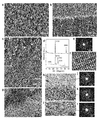
- A XRD pattern (upper side) of ACP nanoparticles before molding and M-XRD pattern (lower side) of substrate cross section after compression molding. The spike peak indicated by the black circle is due to the scratch on the imaging plate and not from the sample.
- B Cross-sectional SEM image of the substrate. Nanoparticle size is 80nm or less (considering about 15nm thickness of platinum coating layer).
- C TEM image of substrate nanoparticles observed using a crushed sample.
- D SAED pattern of nanoparticles.
- FIG. 1 The figure which shows the AFM image about the ACP board
- A Surface pressure AFM image and root mean square roughness (R q ) and its dispersion of a molding pressure 5 MPa substrate.
- B XRD pattern of GL after dipping the surface of a 5 MPa substrate.
- C SEM bird's-eye view of GL after dipping the surface of a 5 MPa substrate.
- D Surface pressure AFM image and root mean square roughness (R q ) and its dispersion of a molding pressure 20 MPa substrate.
- E XRD pattern of GL after dipping the surface of 20MPa substrate.
- G Surface pressure AFM image and root mean square roughness (R q ) and its dispersion of a molding pressure 60 MPa substrate.
- H XRD pattern of GL after dipping the surface of a 60 MPa substrate.
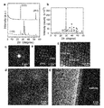
- I SEM bird's-eye view of GL after dipping the surface of a 60 MPa substrate. The drawing which shows the measurement result of the board
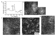
- A M-XRD pattern of the substrate after immersion.
- B IL TEM image and corresponding fast Fourier transform pattern.
- Nanoparticles of 10-20 nm size are observed in IL.
- C High resolution TEM (HR-TEM) image of nanoparticles. Interference fringes corresponding to the spacing of the HAP (002) plane are observed.
- D Fiber crystals in the lower substrate region exhibiting inhomogeneous contrast.
- E HR-TEM image of the fiber. Dashed lines indicate fiber boundaries. Drawing showing STEM-EDS analysis results of an ACP substrate immersed in a mother liquor for 20 hours.
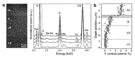
- A Left figure: STEM-HAADF image of cross-section slice of growth sample treated with FIB.
- GL growth layer
- IL intermediate layer
- US upper substrate region (homogeneous region)
- LS lower substrate region (non-homogeneous region)). Dashed lines are the boundaries.
- STEM-EDS spectra corresponding to GL, IL, US, and LS. Mo, W, Na, and Ga are derived from the mesh material of the TEM grid, the protective film used when preparing the FIB sample, the sodium acetate buffer in the solution, and the beam source used during the analysis.
- the belt layer between GL and IL corresponds to the transition layer.
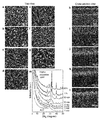
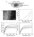
- the drawing which shows the time-division SEM observation and thin film XRD measurement result when an ACP board
- the thickness of the HAP layer is 35-40 ⁇ m.
- B HAP layer after indentation (arrow indicates indentation indentation).
- C Load force vs. displacement curve.
- D Elastic modulus vs. indentation depth profile (representing eight representative data).
- E Hardness vs. indentation depth profile (eight representative data are shown, sample is the same as d). The drawing which shows the measurement result of what immersed the ACP board
- A Surface SEM image of the growth layer. Corresponding lattice image and; (scale bar 2 nm -1 superimpose the top right image, ⁇ 110> observed from zone axis direction)
- White circles correspond to OCP-specific peaks
- black circles correspond to HAP-specific peaks.
- Dashed line GL / IL boundary; Arrow: HAP.
- D STEM-HAADF image of a cross-section slice prepared by FIB treatment.
- E Carbon content mapping by STEM-EDS analysis. Analyzes the same area as the HAADF image.
- F Depth profile of one-dimensional carbon content.
- e Analysis along the dotted line in the figure. Drawing showing time-resolved SEM observation results and STEM-EDS analysis results when the ACC substrate is immersed in the mother liquor.
- the substrates used were ACP, crystalline HAP, crystalline ⁇ -tricalcium phosphate, and crystalline TiO 2 (mixture of anatase and rutile), respectively.
- the substrates used were ACP, crystalline HAP, crystalline ⁇ -tricalcium phosphate, and crystalline TiO 2, respectively . Except for the ACP substrate, spherulite growth of nanorods is observed in a complicated manner. The thickness, homogeneity of GL, close packing degree of nanorods, and c-axis orientation are remarkably superior when an ACP substrate is used.
- Nanorod A columnar body with a width of 10 nm or more and 400 nm or less as observed by SEM or the like.
- Nanorods are densely packed About 90% or more of the number of measurements when the distance between the nanorods adjacent to each other in any direction is sequentially measured for the observation image of the nanorod group by SEM etc. The interval of is 50 nm or less.
- ⁇ Oriented in the same direction '' The lowest surface corresponding to the dominant crystallographic orientation direction when XRD measurement was performed with X-rays incident from the direction considered to be the average orientation direction of HAP nanorods and 2 ⁇ was changed.
- the ratio between the peak intensity of the index and the peak intensity corresponding to diffraction from other than the dominant orientation direction, particularly the peak intensity corresponding to (211) diffraction corresponding to the strongest diffraction line of HAP in the powder XRD, is 10: 1 or more.
- High crystallinity In the XRD or M-XRD measurement pattern, all peaks can be attributed to HAP, 2 ⁇ has a peak specific to HAP near 10.8 °, and 2 ⁇ has a peak near 31 to 33 ° (HAP (211), (112), (300) regions corresponding to diffraction) are separated into two or three.
- ACC amorphous calcium carbonate
- ACP Amorphous calcium phosphate
- FIB focused-ion-beam
- Focused ion beam GL grown layer
- HAP hydroxyapatite
- HR-TEM High-resolution TEM
- High-resolution transmission electron microscope IL intermediate layer
- Intermediate layer LS lower substrate
- M-XRD Micro-beam X-ray diffraction
- OCP octacalcium phosphate
- Octacalcium phosphate SAED selected area electron diffraction
- SEM scanning electron microscope
- STEM-EDS scanning-TEM energy dispersion spectroscopy
- STEM -HAADF Scanning-TEM high-angle annular
- calcium ions are filled with amorphous nanoparticles of calcium salt having a diameter of 500 nm or less, and at least a part of a flat surface of a base material (preferably a substrate) having a flat surface is preferably calcium ions,
- An artificial enamel formed by immersing in a mother liquor containing phosphate ions and fluorine ions is formed or manufactured.
- the manufactured artificial enamel has a structure in which a large number of hydroxyapatite (HAP) nanorods are densely oriented in the same crystal orientation.
- HAP hydroxyapatite
- amorphous nanoparticles of the water-soluble calcium salt used when forming the substrate include, but are not limited to, ACP and ACC, for example, amorphous calcium sulfate and amorphous calcium nitrate can be used.
- Calcium salt amorphous nanoparticles having a diameter of 500 nm or less, preferably 200 nm or less, more preferably 100 nm or less are used.
- the lower limit diameter need not be limited, but can be 5 nm or more for ease of use.
- the largest diameter among the diameters passing through the center of gravity is the major axis, and the smallest is the minor axis.
- the nanoparticles are amorphous can be confirmed by XRD, M-XRD and SAED patterns, and observation of the inside of the particles by TEM.
- the amorphous nanoparticles used in the present invention are water-soluble as will be apparent from the examples described later.
- the degree of water solubility is considered to be 1 ⁇ M or more in pure water at room temperature.
- the growth rate of the HAP nanorods formed on the substrate surface is slow and the spherulitic structure develops, as seen in the comparative example described later.
- a homogeneous artificial enamel as in the case of using amorphous nanoparticles is not formed.
- a substrate on which artificial enamel is formed on the surface can be prepared by compression molding amorphous nanoparticles. At least a part of the surface of the substrate is formed flat, and at least a part of the flat surface is immersed in the mother liquor.
- the flat surface immersed in the mother liquor has a flatness defined by JISB0621 (the magnitude of deviation from a geometrically correct plane) of 200 nm or less (preferably 100 nm or less, more preferably 50 nm), and / or
- the root mean square roughness Rq specified by JISB0601 is 200 nm or less (preferably 100 nm or less, more preferably 50 nm or less).
- the flatness can be measured by a known means such as a flatness tester.
- both surfaces of the substrate may be formed flat, or the entire surface or part of one surface may be formed flat.
- Conditions such as temperature and humidity at the time of compression molding are permissible as long as they do not cause phase transition to the crystal phase.
- the room temperature is preferably low humidity (20% or less).
- the compression pressure at the time of compression molding is permissible as long as the substrate having a flat surface at least partially can be molded. Usually, it is 1 MPa or more.
- the allowable upper limit can be set to 100 MPa, 150 MPa, 200 MPa, or the like depending on the molding machine or mold to be used.
- the width of the oriented nanorods of artificial enamel formed on the substrate surface becomes smaller than when the pressure is decreased.
- the base material is coated with a substance that does not react with the calcium phosphate solution and does not cause precipitation of calcium phosphate salts on the surface other than the flat surface immersed in the mother liquor, thereby suppressing wasteful consumption of calcium phosphate in the mother liquor.
- a covering material include, but are not limited to, a resin and a metal.
- the mother liquor for immersing the substrate contains calcium ions, phosphate ions, and fluorine ions.
- the concentration of calcium ions and phosphate ions is 0.2 mM or more, preferably 1 mM or more. When the concentration is less than 0.2 mM, oriented nanorods are not formed, or the formation rate is slow. On the other hand, when the concentration is high, the formation rate of artificial enamel increases, but when the concentration is too high, homogeneous nucleation (precipitation) is likely to occur during substrate immersion, and high crystallinity oriented in the c-axis direction. It becomes difficult to obtain HAP.
- the upper limit of the concentration of calcium ions and phosphate ions at which homogeneous nucleation (precipitation) does not occur during substrate immersion depends on the pH of the mother liquor and the presence / absence of stirring of the mother liquor.
- the pH of the mother liquor is relatively low at about 6.2
- the upper limit of the concentration is about 4 mM, but when the pH is relatively high at about 7.4, it is necessary to lower it to about 1 mM or less.
- homogeneous nucleation is likely to occur, but when the pH is about 6.2, if the concentration is 2 mM or less, the mother liquor is stirred to increase the formation rate of artificial enamel. It is also acceptable.
- the concentration of fluorine ions is 0.9 to 100 ppm (preferably 1 to 50 ppm, more preferably 2 to 20 ppm).
- the mother liquor does not contain fluorine ions or the concentration of fluorine ions is less than 0.9 ppm, HAP nanorods are not formed even if calcium ions and phosphate ions are preferred concentrations for artificial enamel formation.
- the substrate immersed in the mother liquor is preferably placed on the bottom of the container. In that case, it is preferable to install so that the bottom of a container and the base-material surface may become horizontal.
- the immersion time is not limited, but depending on the required thickness of the artificial enamel layer, 1 hour, 6 hours, 12 hours, 1 day, 2 days, 3 days, 5 days, 10 days, etc., 0.5 hours to It can be set appropriately as in the range of about 30 days.
- the mother liquor for forming the artificial enamel has a pH of usually about 6 to 7, and the mother liquor temperature can be 0 to 60 ° C. (preferably 10 to 50 ° C., more preferably 20 to 40 ° C.). is there. Therefore, if the mother liquor temperature is set within the range of 20 to 40 ° C, the artificial enamel will be used in combination with the above pH value under conditions acceptable to living organisms such as the human body (ie, simulated physiological environment). Can be easily and efficiently formed or manufactured.
- the formed artificial enamel has a structure in which a large number of HAP nanorods are densely oriented in the same direction.
- the width of the HAP nanorod is about 10 nm to 400 nm.
- the length of the HAP nanorods depends on the immersion period, but in the examples described below, those of about several ⁇ m (length / width of 10 or more) are obtained after immersion for 20 hours (the length of each nanorod is several ( ⁇ m.
- the growth layer has a number of nanorods stacked in stages, and one nanorod is not necessarily connected from the beginning to the end of the growth layer).
- the growth rate of the growth layer on which nanorods are stacked is much superior to that of the prior art, and the artificial enamel formation method of the present invention is very efficient. It can be said that
- Measurement or analysis equipment used in Examples, treatment method for measurement / analysis, sample >> The measurement or analysis equipment, the processing method for measurement / analysis, the sample, etc. used in the examples and comparative examples relating to the present invention are as follows.
- XRD X-ray diffraction
- the substrate after being immersed in a fluorine-containing mother liquor or a fluorine-free mother liquor for 20 hours was evaluated with a powder XRD apparatus (40 kV, 100 mA).
- the peak position of the obtained pattern was compared with those of calcium phosphates and calcium carbonates registered in the JCPDS card, and the sample was identified.
- M-XRD The growth sample was cut perpendicular to the substrate surface and evaluated by M-XRD (the thickness of the cut sample was 200 to 400 ⁇ m).
- the beam of the X-ray device was condensed to 100 ⁇ m by a collimator and irradiated onto the surface of the GL or the thin piece of the substrate from the vertical direction.
- the voltage and current at that time were 50 kV and 30 mA.
- the measurement sample was fixed to the tip of the glass capillary with double-sided tape, and diffraction X-rays were recorded on the imaging plate.
- the digital data on the imaging plate was converted to an intensity versus 2 ⁇ relationship using DISPLAY software.
- the final peak position was compared with those of calcium phosphates and calcium carbonates registered in the JCPDS card, and the sample was identified.
- the surface of the growth sample was evaluated by thin film XRD.
- the voltage and current conditions at that time were 45 kV and 200 mA.
- the substrate size used for thin film XRD measurement was 2x5x0.5mm.
- the final peak position was compared with those of calcium phosphates and calcium carbonates registered in the JCPDS card, and the sample was identified.
- FE-SEM FE-SEM After the sample (GL or substrate) was coated with platinum, FE-SEM observation was performed at an acceleration voltage of 5 kV. In order to prevent sample charge-up, the thickness of the coated platinum layer was about 15 nm.
- a slice of a cross-sectional sample was prepared by an FIB apparatus using Ga ions. The sample was thinned to about 150 nm with an acceleration voltage of 40 kV, and then further thinned to about 100 nm with an acceleration voltage of 10 kV. The treated sample was placed on a TEM sample grid using a molybdenum mesh.
- TEM TEM Sample observation was performed using an analytical TEM at an acceleration voltage of 200 kV. SAED measurement is usually performed in an area of 800 nm ⁇ , but at the time of transition layer observation, measurement at 200 nm ⁇ was also used.
- the electron beam was narrowed down to about 1 nm in diameter by a TEM pre-specimen lens, and the surface of the slice sample prepared by FIB processing was raster scanned.
- the HAADF image was captured by capturing the scattered electrons scattered at a high angle with an annular detector.
- Optical microscope A confocal differential interference microscope was used with white light. The observation sample is a cross-sectional cut of the ACP substrate after being immersed in the mother liquor for 20 hours.
- AFM MultiMode-8 atomic force microscope
- Example 1 Formation of artificial enamel using ACP substrate >> (Preparation of calcium phosphate solution used to create ACP nanoparticles) Reagent grade CaCl 2 and Na 2 HPO 4 were each dissolved in milliQ water (ultra pure water, specific resistance: 18.2 M ⁇ , TOC: 3 ppb) to a concentration of 10 mM. The prepared solution was temporarily stored in a 4 ° C. incubator, and then both solutions were mixed at a volume ratio of 1: 1 for 1 minute while stirring. The mixed solution was vacuum filtered using a 0.22 ⁇ m filter at room temperature. The precipitate (ACP) remaining on the filter was quickly washed with milli-Q water to remove residual dust, and then washed with 99.5% ethanol to stop the reaction. ACP nanoparticles were frozen at ⁇ 70 ° C. for 30 minutes, then dried in vacuo overnight and stored in a dry incubator (humidity about 20%, temperature about 23 ° C.).
- ACP substrate (Production of ACP substrate) About 10 mg of ACP nanoparticles were compression-molded at 20 MPa for 10 minutes at room temperature using a hydraulically driven oil compressor to form a 2 ⁇ 10 ⁇ 0.5 mm substrate. This substrate is processed into a size of 2 ⁇ 2 ⁇ 0.5 mm using a medical knife. XRD measurement was performed immediately before forming the nanoparticle into a substrate, and it was confirmed that it was the same as the XRD pattern measured immediately after nanoparticle preparation.
- the acetate ion concentration in the adjusted phosphate buffer solution is 50 mM.
- a small amount of CaCl 2 solution was mixed in the above phosphate buffer solution at a volume ratio of 1: 249.
- the calcium ion concentration in the mixed calcium phosphate solution becomes 4.00 mM and the phosphate ion concentration becomes 3.98 mM.
- the NaF solution was mixed with the calcium phosphate solution at a volume ratio of 1:99 to obtain a final mother liquor.
- the calcium ion concentration in the mother liquor is 3.96 mM
- the phosphate ion concentration is 3.94 mM
- the fluorine ion concentration is 0.526 mM (corresponding to 10 ppm).
- the calcium and phosphate ion concentration of about 4 mM is close to the upper limit concentration that can keep the solution for 2 days without precipitation.
- About 35 mL of the prepared mother liquor was poured into a polystyrene container (volume of about 50 mL), covered and kept in an incubator (37.0 ⁇ 0.5 ° C.).
- the substrate was placed on the bottom of the container, and the bottom of the container and the substrate surface were set to be horizontal.
- the volume ratio of the mother liquor to the substrate was about 17,500: 1. While the substrate was immersed, the mother liquor was not stirred. When the target immersion time was reached, the substrate was quickly removed from the solution, washed with milliQ water, further washed with a 99.5% ethanol solution, and dried.
- GL consists of a set of rods with very high micrometer length aspect ratio (length / width of 10 or more), and individual rods are arranged in one direction from the initial growth stage to the final growth stage.
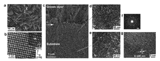
- Fig. 2b, c A dense intermediate layer (IL) having a thickness of about 1.2 ⁇ m was observed between the substrate and the GL (FIG. 2c). The contrast of IL was darker than that of the substrate, and was structurally integrated with the substrate.
- TEM and SAED observations using microtome ultrathin slices revealed that IL is not amorphous but a crystalline material with random orientation.
- SAED measurements also showed that there was a transition layer (about 300 nm) between the IL and the rod crystal, where the crystal orientation changed from random to gradually oriented. The transition layer then transitioned smoothly to a fully oriented nanorod crystal layer.
- the intensity ratio between the peak intensity of the lowest plane index (002) corresponding to the dominant crystallographic orientation direction and the peak intensity of (211) when XRD measurement of completely random orientation HAP powder is 50: 1 or more Met. From this, it can be said that many HAP nanorods constituting GL are oriented in the same direction.
- GL consists of c-axis oriented highly crystalline HAP nanorods.
- XRD data gives average information.
- HR-TEM High-resolution TEM
- SAED measurement were performed using the crushed GL sample in order to confirm whether the individual crystals in the GL were really crystalline HAP.
- the nanorod-type crystal had a regular atomic arrangement, and a spacing of 0.819 and 0.693 nm was observed. These correspond to the (100) and (001) plane spacings of HAP, respectively (Fig. 2e, f).
- the nanorod-type HAP is fused with the nanoparticles in the transition layer at the root, which is consistent with the low-magnification TEM image results.
- HAP nanorod structure formation is not affected by the roughness of the ACP substrate surface before immersion.
- the basic nanorod structure was the same even when the compression pressure during substrate formation was varied in the range of 5-60 MPa (Figure 3), the higher the compression pressure, the smaller the nanorod width. was observed (FIGS. 3c, f, i).
- IL Since microtome processing often destroys the growth sample, cross-section flakes were created by FIB processing. TEM observation of this thin piece and SAED measurement from the GL to the substrate at a step of about 500 nm were performed. From the STEM-HAADF image, IL exhibits a homogeneous contrast despite having many voids (Fig. 2h), while the substrate region is due to the upper region (US) showing a homogeneous contrast and the fibrous pattern. It became clear that it can be classified into the lower region (LS) exhibiting inhomogeneous contrast (FIG. 2i). Unlike the SAED pattern for GL (FIG. 2j), the SA SA pattern of IL was basically the same as that of the substrate, showing a randomly oriented crystalline structure (FIG. 2k, l).
- the substrate has undergone a phase transition from ACP to HAP as the solution penetrates into the gaps between the substrate ACP particles.
- the question is whether IL was formed by ACP phase transition or by direct precipitation of HAP nanoparticles from solution.
- STEM-EDS analysis of the growth sample, time-resolved SEM observation of the growth process, and thin film XRD measurement were performed.
- STEM-EDS analysis of growth HAP layer STEM-EDS analysis revealed that GL and IL contain fluorine, while the substrate, particularly the LS region, contains almost no fluorine (FIG. 5a).
- the Ca Ca / P molar ratio of IL is close to that of the substrate.
- Time-resolved SEM observation and thin film XRD measurement of nanorod structure formation process Time-resolved SEM observation and thin film XRD measurement were performed to clarify the initial growth process in which IL formation occurs. From the surface SEM image, the substrate surface was slightly dissolved in 1 minute after the substrate was immersed in the solution, and particles of 50 to 80 nm were clearly observed (FIG. 6a). The surface subsequently migrated to the root structure of the tree after 3 minutes (FIG. 6b), and the roots of these trees merged to form a particle-like structure after 5 minutes (FIG. 6c). Between 10 and 20 minutes after immersion, the surface was covered with nanoparticles of 50 nm or less (FIGS. 6d and e).
- nanoparticles changed to a nanorod structure after 30 minutes and the rod width and length increased from 30 minutes to 1 hour (FIG. 6f, g). From the cross-sectional SEM observation of the sample, it can be clearly seen that IL is formed after 5 minutes (FIG. 6h). After 10 minutes, the nanoparticles grew in the vertical direction, and after 20 minutes, the growth was accelerated to form a column-like morphology (FIGS. 6i, j). The column changed into nanorods (about 60 nm wide, about 500 nm long) with a tapered tip after 30 minutes (FIG. 6 k), and these rods grew to about 120 nm wide and about 900 nm long after 1 hour ( FIG. 6l).
- Thin film XRD results showed that the surface changed from ACP to low crystalline HAP in the first 5 minutes (FIG. 6m).
- crystalline IL was formed by phase transition from ACP nanoparticles.
- the thin film XRD pattern shows that the crystallinity of the HAP nanorods gradually improves between 30 minutes and 1 hour after immersion, and that essentially the same structure as enamel is established after 1 hour.
- the HAP nanorod growth layer reaches a thickness of about 40 ⁇ m after 2 days while maintaining c-axis orientation.
- the elastic modulus and hardness of this growth layer were measured from the direction perpendicular to the c-axis of the crystal using the nanoindentation method.
- the elastic modulus (average of data between 400 to 600 nm indentation depth of each sample) is 63.4 ⁇ 9.2 GPa
- hardness (average of data between 400 to 600 nm indentation depth of each sample) was 2.87 ⁇ 0.41 GPa (FIG. 7).
- the elastic modulus decreased to 25-35 GPa.
- the substrate after immersion was evaluated in detail.
- Example 2 Formation of artificial enamel using ACC substrate >> (Preparation of calcium carbonate solution used to make ACC nanoparticles) Reagent grade CaCl 2 and Na 2 CO 3 were each dissolved in milliQ water to a concentration of 20 mM. Both prepared solutions were mixed at a volume ratio of 1: 1 for 1 minute with stirring in a 4 ° C. environment. The subsequent process for creating ACC nanoparticles is the same as that for ACP nanoparticles. The final ACC nanoparticles were stored at -20 ° C. This is to prevent the phase transition from ACC to crystalline calcite and vaterite.
- ACC substrate was prepared and processed in the same manner as the preparation and processing of the ACP substrate described above except that ACC nanoparticles were used instead of the ACP nanoparticles. XRD measurement was performed immediately before forming the nanoparticle into a substrate, and it was confirmed that it was the same as the XRD pattern measured immediately after nanoparticle preparation.
- the intensity ratio between the peak intensity of the lowest plane index (002) corresponding to the dominant crystallographic orientation direction and the peak intensity of (211) when XRD measurement of completely random orientation HAP powder is about 40. : 1. From this, it can be said that the HAP nanorods constituting the GL are oriented in the same direction.
- the layer consists of randomly oriented 10-20 nm low crystalline HAP nanoparticles (FIG. 11c, d). From HR-TEM observation and SAED measurement on the dice-like material found in the substrate, these were confirmed to be calcite crystals (FIG. 11e, f). Since lattice fringes corresponding to HAP are seen on the calcite crystal (FIG. 11g), the low aspect ratio nanorods (arrows in FIG. 12c) deposited on the dice-like material in the SEM image were HAP.
- ACC nanoparticles dissolved in the early stage of the reaction release calcium ions and carbonate ions near the surface, which increases the degree of supersaturation with respect to HAP. For this reason, HAP overgrows around the ACC particles and finally forms IL.
- the fluorine content of IL is 1.36 ⁇ 0.17%, 1.8 times higher than when using an ACP substrate.
- This fact also supports the hypothesis that HAP nanoparticles formed overgrowth around ACC nanoparticles (FIG. 13g).
- This formation process is different from the mechanism in which HAP nanoparticles in IL are formed by ACP-HAP direct phase transition when using an ACP substrate.
- the (10-14) plane of calcite crystal or compression-molded calcite microcrystal is used as a substrate instead of ACC nanoparticles, a highly crystalline c-axis oriented HAP nanorod structure is not formed. This fact indicates that amorphous nanoparticles play an important role in HAP nanorod structure formation.
- Comparative Example 1 Comparative Experiment Using Crystalline Nanoparticle Substrate >> (Preparation of crystalline nanoparticle substrate) About 10 mg of commercially available HAP nanoparticles (size 100 nm or less), ⁇ -calcium triphosphate nanoparticles, and commercially available TiO 2 nanoparticles (size 10 to 15 nm, a mixture of anatase and rutile) were each compression-molded at 20 MPa to obtain a substrate.
- ⁇ -calcium triphosphate nanoparticles were obtained by pulverizing commercially available ⁇ -calcium triphosphate microcrystals in 99.5% ethanol solution using ZrO 2 beads (diameter: about 30 ⁇ m), and grinding the slurry containing the pulverized product at 15,000 in a 4 ° C environment. After centrifugation at rpm for 30 minutes, the supernatant was filtered and dried, and the average size was 60 nm or less.
- crystalline growth experiment using crystalline nanoparticle substrate instead of the ACP substrate, a crystalline HAP nanoparticle substrate, a crystalline ⁇ -tricalcium phosphate nanoparticle substrate, or a crystalline TiO 2 nanoparticle substrate is used, except that a high crystalline HAP on the ACP substrate is used.
- each substrate was immersed in a calcium phosphate mother liquor containing 0.526 mM fluorine for 20 hours and then observed.
- the GL thickness was thinner than when using an ACP substrate or ACC substrate, that is, the formation speed was significantly lower, and the spherulite structure As can be seen from the frequent observation, the homogeneity of the nanorod group was far inferior to that when the amorphous nanoparticle substrate was used.
- the lowest plane index corresponding to the dominant crystallographic orientation direction when using a crystalline HAP nanoparticle substrate, a crystalline ⁇ -calcium triphosphate nanoparticle substrate, or a crystalline TiO 2 nanoparticle substrate (002)
- the intensity ratio between the peak intensity corresponding to (211) diffraction and the peak intensity corresponding to (211) diffraction when XRD measurement was performed on a completely random-oriented HAP powder was 40: 1 or less.
- STEM-EDS measurements on this HAP nanorod showed that x was about 0.8.
- this fluorine-substituted HAP nanorod is growing as the most stable phase in the mother liquor.
- new HAP nucleates on each nanorod and repeats homoepitaxial growth to form a thick enamel-like HAP layer. Even in this growth stage, of course, individual crystals are effectively grown perpendicularly to the substrate by (macroscopic) geometrical selection.
- HAP nanorod structure Even when crystalline nanoparticles (HAP, ⁇ -calcium triphosphate, and TiO 2 ) of various sizes with poor reactivity are used as the substrate, the HAP nanorod structure can be constructed. However, spherulite growth frequently occurs in the formation process, and as a result, the degree of GL c-axis orientation and homogeneity are inferior to those in the case of using amorphous nanoparticles (FIG. 14). This experimental result shows that the formation of HAP nanorod structures is not simply governed by the size of the nanoparticles. However, the nanoparticles themselves are an important factor for the construction of the nanorod structure.
- HAP nanorods does not require nanoscale surface-designed substrates or highly oriented single crystal surfaces.
- a substrate formed by compression-molding highly reactive amorphous nanoparticles containing calcium ions in a calcium phosphate solution containing fluorine ions an IL consisting of closely packed crystalline HAP nanoparticles (with random orientation) is formed.
- an enamel-like structure develops immediately. This reaction can proceed even in a simulated physiological environment.
- the amorphous nature of the substrate is much more important than the type of substrate.
- the technique we have developed can be applied to the formation of various types of nanorod structures including HAP.
- an artificial enamel in which a large number of hydroxyapatite nanorods are densely packed (or closely packed) and oriented in the same direction can be easily and efficiently under conditions acceptable to a living body such as a human body. Since it can be formed or manufactured, it is expected to be used for the treatment of missing teeth, caries, and manufacture of dentures.
Landscapes
- Health & Medical Sciences (AREA)
- Chemical & Material Sciences (AREA)
- Organic Chemistry (AREA)
- Oral & Maxillofacial Surgery (AREA)
- Inorganic Chemistry (AREA)
- Life Sciences & Earth Sciences (AREA)
- Animal Behavior & Ethology (AREA)
- Public Health (AREA)
- Veterinary Medicine (AREA)
- General Health & Medical Sciences (AREA)
- Epidemiology (AREA)
- Dermatology (AREA)
- Geology (AREA)
- Plastic & Reconstructive Surgery (AREA)
- Medicinal Chemistry (AREA)
- Transplantation (AREA)
- Materials For Medical Uses (AREA)
- Dental Preparations (AREA)
- Compounds Of Alkaline-Earth Elements, Aluminum Or Rare-Earth Metals (AREA)
- Crystals, And After-Treatments Of Crystals (AREA)
Abstract
多数の水酸アパタイトナノロッドが密集して同一結晶方位に配向した人工エナメル質の新規で簡便な形成方法を提供することを課題とする。径が500nm以下のカルシウム塩のアモルファスナノ粒子の充填体からなり、少なくとも一部に平坦な表面を有する基材の平坦な表面の少なくとも一部をカルシウムイオン、リン酸イオン、フッ素イオンを含む母液に浸漬することにより基材表面に人工エナメル質(水酸アパタイトナノロッドが密集して同一結晶方位に配向した構造)を形成する。前記基材は、水溶性カルシウム塩のアモルファスナノ粒子を圧縮成形することにより調製する。
Description
本発明は、アモルファスナノ粒子を利用した人工エナメル質の形成方法に関するものである。
配向したナノ結晶群からなる構造物は、優れた物理化学的性質を呈することが知られている。それらの代表はZnO, TiO2, Fe2O3等の金属酸化物のナノロッド型構造であり、光電子材料、センサー、エネルギー変換材料、水分解材料として幅広く使用されている。生物体は、この配向型ナノ結晶構造を進化の過程で自然に獲得し、硬組織として発達させた。その代表例の一つがエナメル質である。
ヒト歯のエナメル質はc軸方向に配向し、水酸基の一部をフッ素置換した高結晶性水酸アパタイト(以下、「HAP」ということがある。)のナノロッド(約60nm幅)からなり、その階層的な束状構造は高い弾性率(約60~110GPa)と硬度(約2~6GPa)を呈する。エナメル質類似構造の構築は20年以上に渡って重要な研究テーマであり、多くの手法が提案されている(非特許文献1参照)。この研究の目的の一つは、言うまでもなく人工エナメル質を欠損歯、特に虫歯の治療に利用することであろう。
HAPのナノロッド結晶自体は、少量のフッ素を含んだリン酸カルシウム溶液から形成可能なことが、既に知られている(例えば、非特許文献2参照)。従って、解明すべき課題は「一方向に配向したHAPナノロッド結晶群(すなわちエナメル質構造)を基板上に如何に迅速構築するか」、である。この課題を克服するため、リン酸カルシウムからなるホモ基板、あるいはHAPを誘導する性質を持つ(リン酸カルシウム以外の)ヘテロ基板を用いて、一方向配向したHAPナノロッド構造を構築する研究が続けられてきた。しかし、過去のアプローチは配向ナノロッド構造を構築するために非常に複雑なプロセスを必要とした。それらは、極端に低い溶液pH(非特許文献3参照)、高温(例えば、非特許文献4)、エナメルタンパク質や真珠層から抽出した水溶性有機マトリックスの溶液中への添加(非特許文献5)、HAPを誘導するための基板表面の修飾(非特許文献6)、等である。更に、これらの複雑な手法を駆使しても、成長したHAPナノロッド層は薄く、場合によっては配向度が非常に低いこともあった。
Hench, L. L. Bioceramics: From concept to clinic. J. Am. Ceram. Soc. 74, 1487-1510 (1991)
Zhang, H. G. & Zhu, Q. Surfactant-assisted preparation of fluoride-substituted hydroxyapatite nanorods. Mater. Lett. 59, 3054-3058 (2005)
Yamagishi, K. et al. A synthetic enamel for rapid tooth repair. Nature 433, 819 (2005)
Chen, H. et al. Acellular synthesis of a human enamel-like microstructure. Adv. Mater. 18, 1846-1851 (2006)
Fowler, C. E., Li, M., Mann, S. & Margolis, H. C. Influence of surfactant assembly on the formation of calcium phosphate materials-A model for dental enamel formation. J. Mater. Chem. 15, 3317-3325 (2005).
Hayakawa, S. et al. Preparation of nanometer-scale rod array of hydroxyapatite crystal. Acta Biomater. 5, 2152-2160 (2009)
本発明者は、上述のような過去の研究について調査する過程で、過去のアプローチは、配向ナノロッド構造を構築するために、人体等の生命体が許容し得ない形成条件や非常に複雑なプロセスを必要とするという問題点を有することを認識した。
本発明は、上述のような過去の研究や本発明者が認識した前記問題点を背景としてなされたものであり、人工エナメル質の新規で簡便な製造方法を提供することを課題とする。
本発明者は、前記課題のもとで、人工エナメル質構造を、溶液中に一切の高分子の添加物なしに擬似生理環境場で構築する研究を進め、後記<実施例、比較例についての考察>などにおいて述べたような様々な知見を得た。
本発明は、そのような知見に基づいて完成したものであり、本件では、次のような発明が提供される。
<1>径が500nm以下のカルシウム塩のアモルファスナノ粒子の充填体からなり、少なくとも一部に平坦な表面を有する基材の平坦な表面の少なくとも一部をカルシウムイオン、リン酸イオン、フッ素イオンを含有する母液に浸漬することを含む人工エナメル質の形成方法。
<2>前記基材を構成するアモルファスナノ粒子は、アモルファスリン酸カルシウム、アモルファス炭酸カルシウム、アモルファス硫酸カルシウム、アモルファス硝酸カルシウムからなる群から選択される1種又は2種以上である<1>に記載の人工エナメル質の形成方法。
<3>前記母液は、カルシウムイオン濃度が0.2~5mM、リン酸イオン濃度が0.2~5mMの水溶液である<1>又は<2>に記載の人工エナメル質の形成方法。
<4>カルシウムイオン濃度が0.2~2mM、リン酸イオン濃度が0.2~2mMの場合に、基材を浸漬中の母液を撹拌する<3>に記載の人工エナメル質の形成方法。
<5>前記母液は、フッ素イオン濃度が0.9~100ppmである<1>~<4>のいずれか1項に記載の人工エナメル質の形成方法。
<6>前記母液の温度が0~60℃である<1>~<5>のいずれか1項に記載の人工エナメル質の形成方法。
<7><1>~<6>のいずれか1項に記載の人工エナメル質の形成方法において、カルシウム塩のアモルファスナノ粒子を圧縮成形することにより前記基材を調製することを含む人工エナメル質の形成方法。
<8>前記圧縮成形時の圧縮圧力が1MPa以上である<7>に記載の人工エナメル質の形成方法。
<9><8>に記載の人工エナメル質の形成方法において、前記圧縮成形時の圧力を調整することにより、人工エナメル質を構成する水酸アパタイトナノロッドの幅を調整することを含む人工エナメル質の形成方法。
<1>径が500nm以下のカルシウム塩のアモルファスナノ粒子の充填体からなり、少なくとも一部に平坦な表面を有する基材の平坦な表面の少なくとも一部をカルシウムイオン、リン酸イオン、フッ素イオンを含有する母液に浸漬することを含む人工エナメル質の形成方法。
<2>前記基材を構成するアモルファスナノ粒子は、アモルファスリン酸カルシウム、アモルファス炭酸カルシウム、アモルファス硫酸カルシウム、アモルファス硝酸カルシウムからなる群から選択される1種又は2種以上である<1>に記載の人工エナメル質の形成方法。
<3>前記母液は、カルシウムイオン濃度が0.2~5mM、リン酸イオン濃度が0.2~5mMの水溶液である<1>又は<2>に記載の人工エナメル質の形成方法。
<4>カルシウムイオン濃度が0.2~2mM、リン酸イオン濃度が0.2~2mMの場合に、基材を浸漬中の母液を撹拌する<3>に記載の人工エナメル質の形成方法。
<5>前記母液は、フッ素イオン濃度が0.9~100ppmである<1>~<4>のいずれか1項に記載の人工エナメル質の形成方法。
<6>前記母液の温度が0~60℃である<1>~<5>のいずれか1項に記載の人工エナメル質の形成方法。
<7><1>~<6>のいずれか1項に記載の人工エナメル質の形成方法において、カルシウム塩のアモルファスナノ粒子を圧縮成形することにより前記基材を調製することを含む人工エナメル質の形成方法。
<8>前記圧縮成形時の圧縮圧力が1MPa以上である<7>に記載の人工エナメル質の形成方法。
<9><8>に記載の人工エナメル質の形成方法において、前記圧縮成形時の圧力を調整することにより、人工エナメル質を構成する水酸アパタイトナノロッドの幅を調整することを含む人工エナメル質の形成方法。
本発明は、次のような態様を含むことができる。
<10><3>に記載の人工エナメル質の形成方法において、カルシウムイオン濃度が2mM超5mM以下、リン酸イオン濃度が2mM超5mM以下の場合に、母液を無撹拌とすることを含む人工エナメル質の形成方法。
<11><1>~<10>のいずれか1項に記載の人工エナメル質の形成方法において、人工エナメル質を形成する前記表面以外をリン酸カルシウム溶液と反応せず且つその表面にリン酸カルシウム塩の析出を起こさない物質で被覆することを含む人工エナメル質の形成方法。
<12>前記母液は、カルシウムイオン濃度が3~5mM、リン酸イオン濃度が3~5mMである<3>又は<10>に記載の人工エナメル質の形成方法。
<13>前記母液は、フッ素イオン濃度が2~50ppmである<5>に記載の人工エナメル質の形成方法。
<14>前記圧縮成形時の圧縮圧力が5~100MPaである<8>又は<9>に記載の人工エナメル質の形成方法。
<15>アモルファスナノ粒子の径が200nm以下である<1>~<14>のいずれか1項に記載の人工エナメル質の形成方法。
<16>母液の温度が20~40℃である<6>に記載の人工エナメル質の形成方法。
<17>前記基材が基板である<1>~<16>のいずれか1項に記載の人工エナメル質の形成方法。
<18>母液に浸漬する前記平坦な表面は、平面度が200nm以下及び/又は二乗平均平方根粗さRqが200nm以下である<1>~<17>のいずれか1項に記載の人工エナメル質の形成方法。
<10><3>に記載の人工エナメル質の形成方法において、カルシウムイオン濃度が2mM超5mM以下、リン酸イオン濃度が2mM超5mM以下の場合に、母液を無撹拌とすることを含む人工エナメル質の形成方法。
<11><1>~<10>のいずれか1項に記載の人工エナメル質の形成方法において、人工エナメル質を形成する前記表面以外をリン酸カルシウム溶液と反応せず且つその表面にリン酸カルシウム塩の析出を起こさない物質で被覆することを含む人工エナメル質の形成方法。
<12>前記母液は、カルシウムイオン濃度が3~5mM、リン酸イオン濃度が3~5mMである<3>又は<10>に記載の人工エナメル質の形成方法。
<13>前記母液は、フッ素イオン濃度が2~50ppmである<5>に記載の人工エナメル質の形成方法。
<14>前記圧縮成形時の圧縮圧力が5~100MPaである<8>又は<9>に記載の人工エナメル質の形成方法。
<15>アモルファスナノ粒子の径が200nm以下である<1>~<14>のいずれか1項に記載の人工エナメル質の形成方法。
<16>母液の温度が20~40℃である<6>に記載の人工エナメル質の形成方法。
<17>前記基材が基板である<1>~<16>のいずれか1項に記載の人工エナメル質の形成方法。
<18>母液に浸漬する前記平坦な表面は、平面度が200nm以下及び/又は二乗平均平方根粗さRqが200nm以下である<1>~<17>のいずれか1項に記載の人工エナメル質の形成方法。
本発明によれば、人工エナメル質を簡易に効率的に製造することができる。
以下、本発明を実施するための形態を説明する。
なお、本明細書において数値範囲を示す「~」は、その前後に記載される数値を下限値及び上限値として含む意味として使用される。
本明細書において使用される用語「ナノロッド」、「ナノロッドが密集している」、「同方向に配向」、「高結晶性」の意味は、次のとおりである。
「ナノロッド」:SEM等で観察した幅が10nm以上400nm以下の柱状体。
「ナノロッドが密集している」:SEM等によるナノロッド群の鳥瞰視の観察像について、任意の方向に隣接するナノロッド間の先端先細り部以外の間隔を順次測定した際に、測定数の90%以上の間隔が50nm以下であること。
「同方向に配向」:HAPナノロッドの平均的配向方向と見なせる方向からX線を入射して2θを変化させたXRD測定を行った場合において、支配的な結晶学的配向方向に対応する最低面指数のピーク強度と、支配的配向方向以外からの回折に対応するピーク強度、特に粉末XRDにおいてHAPの最強回折線に相当する(211)回折に対応するピーク強度、との比が10:1以上、好適には40:1以上であること、又は/及び、SEM等によるナノロッドの平均的配向方向に略平行な面の観察像について、各ナノロッドの観察平面内の配向方向を測定した際に、90%以上が平均の配向方向からのずれ角度が10°以下の範囲内であること。
「高結晶性」:XRDあるいはM-XRD測定パターンにおいて、全てのピークがHAPに帰属できること、2θが10.8°付近にHAP特有のピークを持つこと、及び2θが31~33°付近のピーク(HAPの(211),(112),(300)回折に対応する領域)が二つないし三つに分離していること。
なお、本明細書において数値範囲を示す「~」は、その前後に記載される数値を下限値及び上限値として含む意味として使用される。
本明細書において使用される用語「ナノロッド」、「ナノロッドが密集している」、「同方向に配向」、「高結晶性」の意味は、次のとおりである。
「ナノロッド」:SEM等で観察した幅が10nm以上400nm以下の柱状体。
「ナノロッドが密集している」:SEM等によるナノロッド群の鳥瞰視の観察像について、任意の方向に隣接するナノロッド間の先端先細り部以外の間隔を順次測定した際に、測定数の90%以上の間隔が50nm以下であること。
「同方向に配向」:HAPナノロッドの平均的配向方向と見なせる方向からX線を入射して2θを変化させたXRD測定を行った場合において、支配的な結晶学的配向方向に対応する最低面指数のピーク強度と、支配的配向方向以外からの回折に対応するピーク強度、特に粉末XRDにおいてHAPの最強回折線に相当する(211)回折に対応するピーク強度、との比が10:1以上、好適には40:1以上であること、又は/及び、SEM等によるナノロッドの平均的配向方向に略平行な面の観察像について、各ナノロッドの観察平面内の配向方向を測定した際に、90%以上が平均の配向方向からのずれ角度が10°以下の範囲内であること。
「高結晶性」:XRDあるいはM-XRD測定パターンにおいて、全てのピークがHAPに帰属できること、2θが10.8°付近にHAP特有のピークを持つこと、及び2θが31~33°付近のピーク(HAPの(211),(112),(300)回折に対応する領域)が二つないし三つに分離していること。
本明細書で使用する主な略号とその意味は、次のとおりである。
ACC(amorphous calcium carbonate):アモルファス炭酸カルシウム
ACP(amorphous calcium phosphate):アモルファスリン酸カルシウム
FIB(focused-ion-beam):収束イオンビーム
GL(grown layer):成長層
HAP(hydroxyapatite):水酸アパタイト
HR-TEM(High-resolution TEM):高分解能透過型電子顕微鏡
IL(intermediate layer):中間層
LS(lower substrate):基板の下部領域
M-XRD(Micro-beam XRD):マイクロビームX線回折
OCP(octacalcium phosphate):リン酸八カルシウム
SAED(selected area electron diffraction):制限視野電子線回折
SEM (scanning electron microscope):走査電子顕微鏡
STEM-EDS(Scanning-TEM energy dispersion spectroscopy):走査透過電子顕微鏡エネルギー分散分光分析
STEM-HAADF(Scanning-TEM high-angle annular dark field):走査透過電子顕微鏡高角度環状暗視野場観察
SUB(substrate):基板
TEM (transmission electron microscope):透過電子顕微鏡
US(upper substrate):基板の上部領域
XRD (X-ray diffraction):X線回折
ACC(amorphous calcium carbonate):アモルファス炭酸カルシウム
ACP(amorphous calcium phosphate):アモルファスリン酸カルシウム
FIB(focused-ion-beam):収束イオンビーム
GL(grown layer):成長層
HAP(hydroxyapatite):水酸アパタイト
HR-TEM(High-resolution TEM):高分解能透過型電子顕微鏡
IL(intermediate layer):中間層
LS(lower substrate):基板の下部領域
M-XRD(Micro-beam XRD):マイクロビームX線回折
OCP(octacalcium phosphate):リン酸八カルシウム
SAED(selected area electron diffraction):制限視野電子線回折
SEM (scanning electron microscope):走査電子顕微鏡
STEM-EDS(Scanning-TEM energy dispersion spectroscopy):走査透過電子顕微鏡エネルギー分散分光分析
STEM-HAADF(Scanning-TEM high-angle annular dark field):走査透過電子顕微鏡高角度環状暗視野場観察
SUB(substrate):基板
TEM (transmission electron microscope):透過電子顕微鏡
US(upper substrate):基板の上部領域
XRD (X-ray diffraction):X線回折
本発明では、径が500nm以下のカルシウム塩のアモルファスナノ粒子の充填体からなり、少なくとも一部に平坦な表面を有する基材(好ましくは、基板)の平坦な表面の少なくとも一部をカルシウムイオン、リン酸イオン、フッ素イオンを含む母液に浸漬することからなる人工エナメル質を形成乃至製造する。製造された人工エナメル質は、多数の水酸アパタイト(HAP)ナノロッドが密集して同一結晶方位に配向した構造を有している。
基材を形成する際に使用する水溶性カルシウム塩のアモルファスナノ粒子としては、例えば、ACPやACCが挙げられるが、それらに限定されず、例えば、アモルファス硫酸カルシウムやアモルファス硝酸カルシウム等も使用できると考えられる。
カルシウム塩のアモルファスナノ粒子は、径が500nm以下、好ましくは200nm以下、より好ましくは100nm以下のものを用いる。下限の径は限定する必要はないが、使用の容易性から5nm以上とすることができる。ナノ粒子の径Dは、SEMなどによる観察により確認することができ、D=(長径+短径)/2として求めることができる。なお、本明細書では、SEMなどで観察されるナノ粒子の二次元投影図において、その重心(形状から見た重心)を通る径のうち最大のものを長径、最小のものを短径とする。
径が500nm超や200nm超、100nm超等の設定された径を超える粒子を含む場合、フィルターを用いた濾別や遠心分離などの適宜の手法により、設定された径を超える粒子を除去することができる。
ナノ粒子がアモルファスであることは、XRD、M-XRD及びSAEDパターン、TEMによる粒子内部観察により確かめることができる。
本発明で用いるアモルファスナノ粒子は、後述の実施例から明らかなように水溶性を有する。その水溶性の程度は、室温で純水中に1μM濃度以上であると考えられる。
基材を形成するナノ粒子が反応性に乏しい結晶性を有する場合、後述の比較例に見られるように、基材表面に形成されるHAPナノロッド群の成長速度は遅く且つ球晶状組織が発達し、アモルファスナノ粒子を用いた場合のような均質な人工エナメル質は形成されない。
カルシウム塩のアモルファスナノ粒子は、径が500nm以下、好ましくは200nm以下、より好ましくは100nm以下のものを用いる。下限の径は限定する必要はないが、使用の容易性から5nm以上とすることができる。ナノ粒子の径Dは、SEMなどによる観察により確認することができ、D=(長径+短径)/2として求めることができる。なお、本明細書では、SEMなどで観察されるナノ粒子の二次元投影図において、その重心(形状から見た重心)を通る径のうち最大のものを長径、最小のものを短径とする。
径が500nm超や200nm超、100nm超等の設定された径を超える粒子を含む場合、フィルターを用いた濾別や遠心分離などの適宜の手法により、設定された径を超える粒子を除去することができる。
ナノ粒子がアモルファスであることは、XRD、M-XRD及びSAEDパターン、TEMによる粒子内部観察により確かめることができる。
本発明で用いるアモルファスナノ粒子は、後述の実施例から明らかなように水溶性を有する。その水溶性の程度は、室温で純水中に1μM濃度以上であると考えられる。
基材を形成するナノ粒子が反応性に乏しい結晶性を有する場合、後述の比較例に見られるように、基材表面に形成されるHAPナノロッド群の成長速度は遅く且つ球晶状組織が発達し、アモルファスナノ粒子を用いた場合のような均質な人工エナメル質は形成されない。
表面に人工エナメル質を形成する基材は、アモルファスナノ粒子を圧縮成形することにより調製することができる。
基材は少なくとも一部の表面を平坦に形成し、平坦な表面の少なくとも一部を母液に浸漬する。母液に浸漬する平坦な表面とは、JISB0621で規定される平面度(幾何学的に正しい平面からの狂いの大きさ)が200nm以下(好ましくは100nm以下、より好ましくは50nm)、及び/又は、JISB0601で規定される二乗平均平方根粗さRqが200nm以下(好ましくは100nm以下、より好ましくは50nm以下)のものをいう。平面度は、フラットネステスタ等の公知の手段により測定することができる。
基材として基板を用いる場合、基板の両面を平坦に形成しても良いし、一方の面の全面や一部を平坦に形成しても良い。
圧縮成形時の温度や湿度等の条件は、結晶相への相転移が生起しない範囲内であれば許容される。好ましくは低湿度(20%以下)の常温である。
圧縮成形時の圧縮の圧力は、少なくとも一部に平坦な表面を有する基材が成形できる範囲内であれば許容される。通常、1MPa以上である。圧縮圧力の上限は限定する必要はないが、一般的には、使用する成形機械や型などにより、100MPa、150MPa、200MPa等のように許容上限を設定することもできる。後述の実施例にみられるように、前記範囲内で圧力を高くした場合、低くした場合よりも、基材表面に形成される人工エナメル質の配向ナノロッドの幅が小さくなる。
基材は、母液に浸漬する平坦な表面以外をリン酸カルシウム溶液と反応せず且つその表面にリン酸カルシウム塩の析出を起こさない物質で被覆することにより、母液中のリン酸カルシウムの無駄な消費を抑制することもできる。そのような被覆の材料としては、限定するものではないが、樹脂や金属などが挙げられる。
基材は少なくとも一部の表面を平坦に形成し、平坦な表面の少なくとも一部を母液に浸漬する。母液に浸漬する平坦な表面とは、JISB0621で規定される平面度(幾何学的に正しい平面からの狂いの大きさ)が200nm以下(好ましくは100nm以下、より好ましくは50nm)、及び/又は、JISB0601で規定される二乗平均平方根粗さRqが200nm以下(好ましくは100nm以下、より好ましくは50nm以下)のものをいう。平面度は、フラットネステスタ等の公知の手段により測定することができる。
基材として基板を用いる場合、基板の両面を平坦に形成しても良いし、一方の面の全面や一部を平坦に形成しても良い。
圧縮成形時の温度や湿度等の条件は、結晶相への相転移が生起しない範囲内であれば許容される。好ましくは低湿度(20%以下)の常温である。
圧縮成形時の圧縮の圧力は、少なくとも一部に平坦な表面を有する基材が成形できる範囲内であれば許容される。通常、1MPa以上である。圧縮圧力の上限は限定する必要はないが、一般的には、使用する成形機械や型などにより、100MPa、150MPa、200MPa等のように許容上限を設定することもできる。後述の実施例にみられるように、前記範囲内で圧力を高くした場合、低くした場合よりも、基材表面に形成される人工エナメル質の配向ナノロッドの幅が小さくなる。
基材は、母液に浸漬する平坦な表面以外をリン酸カルシウム溶液と反応せず且つその表面にリン酸カルシウム塩の析出を起こさない物質で被覆することにより、母液中のリン酸カルシウムの無駄な消費を抑制することもできる。そのような被覆の材料としては、限定するものではないが、樹脂や金属などが挙げられる。
基材浸漬用の母液は、カルシウムイオンとリン酸イオン、及び、フッ素イオンを含むものである。
カルシウムイオンとリン酸イオンの濃度は、0.2mM以上、好ましくは、1mM以上である。濃度が0.2mM未満であると、配向ナノロッドが形成しない、あるいは形成速度が遅くなる。一方、濃度が高いと、人工エナメル質の形成速度が速くなるが、濃度が高すぎると、基材浸漬中に均質核形成(析出)が生起しやすくなり、c軸方向に配向した高結晶性HAPが得られにくくなる。基材浸漬中に均質核形成(析出)が生起しないカルシウムイオンとリン酸イオンの濃度の上限は、母液のpHや母液撹拌の有無などにも依存する。母液のpHが6.2程度の比較的低い場合には、濃度の上限は4mM程度であるが、pHが7.4程度と比較的に高い場合には、1mM以下程度まで下げる必要がある。また、母液を攪拌すると、均質核形成(析出)を生起しやすくなるが、pH6.2程度の場合には濃度が2mM以下であれば、人工エナメル質の形成速度を速めるために母液を攪拌することも許容される。人工エナメル質の形成中、カルシウムイオンとリン酸イオンが低下し、人工エナメル質の形成速度が低下する場合には、カルシウムイオンとリン酸イオンを母液に補充することもできる。
フッ素イオンの濃度は、0.9~100ppm(好ましくは、1~50ppm、より好ましくは2~20ppm)である。母液がフッ素イオンを含まなかったり、フッ素イオンの濃度が0.9ppm未満である場合、カルシウムイオンとリン酸イオンが人工エナメル質形成に好ましい濃度であったとしても、HAPナノロッドは形成されない。
母液中に浸漬される基材は、好ましくは、容器の底に載置するのが好ましい。その際、容器の底と基材表面とが水平になるように設置するのが好ましい。浸漬時間は限定するものではないが、必要な人工エナメル質層の厚みに応じて、1時間、6時間、12時間、1日、2日、3日、5日、10日等、0.5時間~30日程度の範囲のように適宜に設定することができる。
カルシウムイオンとリン酸イオンの濃度は、0.2mM以上、好ましくは、1mM以上である。濃度が0.2mM未満であると、配向ナノロッドが形成しない、あるいは形成速度が遅くなる。一方、濃度が高いと、人工エナメル質の形成速度が速くなるが、濃度が高すぎると、基材浸漬中に均質核形成(析出)が生起しやすくなり、c軸方向に配向した高結晶性HAPが得られにくくなる。基材浸漬中に均質核形成(析出)が生起しないカルシウムイオンとリン酸イオンの濃度の上限は、母液のpHや母液撹拌の有無などにも依存する。母液のpHが6.2程度の比較的低い場合には、濃度の上限は4mM程度であるが、pHが7.4程度と比較的に高い場合には、1mM以下程度まで下げる必要がある。また、母液を攪拌すると、均質核形成(析出)を生起しやすくなるが、pH6.2程度の場合には濃度が2mM以下であれば、人工エナメル質の形成速度を速めるために母液を攪拌することも許容される。人工エナメル質の形成中、カルシウムイオンとリン酸イオンが低下し、人工エナメル質の形成速度が低下する場合には、カルシウムイオンとリン酸イオンを母液に補充することもできる。
フッ素イオンの濃度は、0.9~100ppm(好ましくは、1~50ppm、より好ましくは2~20ppm)である。母液がフッ素イオンを含まなかったり、フッ素イオンの濃度が0.9ppm未満である場合、カルシウムイオンとリン酸イオンが人工エナメル質形成に好ましい濃度であったとしても、HAPナノロッドは形成されない。
母液中に浸漬される基材は、好ましくは、容器の底に載置するのが好ましい。その際、容器の底と基材表面とが水平になるように設置するのが好ましい。浸漬時間は限定するものではないが、必要な人工エナメル質層の厚みに応じて、1時間、6時間、12時間、1日、2日、3日、5日、10日等、0.5時間~30日程度の範囲のように適宜に設定することができる。
人工エナメル質を形成する際の母液は、pHが通常6~7程度であるし、また、母液温度は0~60℃(好ましくは10~50℃、より好ましくは20~40℃)において可能である。それ故、母液温度を20~40℃の範囲内に設定すれば、上記pHの数値と併せて、人体等の生命体に許容可能な条件下(すなわち、擬似生理環境場)において、人工エナメル質を簡易にかつ効率的に形成乃至製造できると言える。
形成された人工エナメル質は、多数のHAPナノロッドが密集して同方向に配向した構造を有している。HAPナノロッドの幅は10nm以上400nm以下程度である。HAPナノロッドの長さは、浸漬期間によるが、後述の実施例では、20時間の浸漬で数μm程度(長さ/幅が10以上)のものが得られている(各ナノロッドの長さは数μm。成長層はいくつものナノロッドが段階的に積み重なっており、一つのナノロッドが成長層の初めから終わりまで必ずしも繋がっている訳ではない)。また、ナノロッドが積み重なった成長層の形成速度(約20時間で20~25μmの厚み)は、従来技術に比べ格段に優れたものであり、本発明の人工エナメル質の形成方法は、非常に効率的なものと言える。
以下、実施例により本発明を更に詳細に説明する。本発明の内容はこの実施例に限定されるものではない。
<<実施例で用いた測定乃至分析機器、測定・分析のための処理方法、サンプル>>
本発明に関する実施例や比較例で用いた測定乃至分析機器、測定・分析のための処理方法、サンプルなどは、次のようなものである。
本発明に関する実施例や比較例で用いた測定乃至分析機器、測定・分析のための処理方法、サンプルなどは、次のようなものである。
(XRD)
フッ素含有母液又はフッ素非含有母液に20時間浸漬後の基板を、粉末XRD装置(40kV, 100mA)で評価した。サンプルは無反射石英基板上に設置し、HAPナノロッドの平均的配向方向と見なせる方向からX線を入射し、スキャン速度2°min-1で2θ=3~60°の範囲で走査した。得られたパターンのピーク位置をJCPDSカードに登録されたリン酸カルシウム類及び炭酸カルシウム類のそれらと比較し、サンプルの同定を行った。
フッ素含有母液又はフッ素非含有母液に20時間浸漬後の基板を、粉末XRD装置(40kV, 100mA)で評価した。サンプルは無反射石英基板上に設置し、HAPナノロッドの平均的配向方向と見なせる方向からX線を入射し、スキャン速度2°min-1で2θ=3~60°の範囲で走査した。得られたパターンのピーク位置をJCPDSカードに登録されたリン酸カルシウム類及び炭酸カルシウム類のそれらと比較し、サンプルの同定を行った。
(M-XRD)
成長サンプルを基板表面に垂直にカットし、M-XRDにより評価した(カットしたサンプルの厚みは200~400μm)。X線装置のビームはコリメータにより100μmに集光し、GLあるいは基板の薄片表面に垂直方向から照射した。その際の電圧と電流は50kV, 30mAであった。測定サンプルは両面テープでガラスキャピラリー先端に固定し、回折X線はイメージングプレート上に記録するようにした。イメージングプレート上のデジタルデータは、DISPLAYソフトウエアを使って強度対2θの関係に変換するようにした。最終的なピーク位置はJCPDSカードに登録されたリン酸カルシウム類及び炭酸カルシウム類のそれらと比較し、サンプルの同定を行うようにした。
成長サンプルを基板表面に垂直にカットし、M-XRDにより評価した(カットしたサンプルの厚みは200~400μm)。X線装置のビームはコリメータにより100μmに集光し、GLあるいは基板の薄片表面に垂直方向から照射した。その際の電圧と電流は50kV, 30mAであった。測定サンプルは両面テープでガラスキャピラリー先端に固定し、回折X線はイメージングプレート上に記録するようにした。イメージングプレート上のデジタルデータは、DISPLAYソフトウエアを使って強度対2θの関係に変換するようにした。最終的なピーク位置はJCPDSカードに登録されたリン酸カルシウム類及び炭酸カルシウム類のそれらと比較し、サンプルの同定を行うようにした。
(薄膜XRD)
成長サンプルの表面を薄膜XRDで評価した。その際の電圧、電流条件は45kV, 200mAであった。薄膜XRD測定に使用した基板サイズは2x5x0.5mmであった。X線の入射角は基板表面に対して0.2°であり、スキャン速度0.1°min-1で2θχ=3~50°の範囲で走査した。最終的なピーク位置はJCPDSカードに登録されたリン酸カルシウム類及び炭酸カルシウム類のそれらと比較し、サンプルの同定を行うようにした。
成長サンプルの表面を薄膜XRDで評価した。その際の電圧、電流条件は45kV, 200mAであった。薄膜XRD測定に使用した基板サイズは2x5x0.5mmであった。X線の入射角は基板表面に対して0.2°であり、スキャン速度0.1°min-1で2θχ=3~50°の範囲で走査した。最終的なピーク位置はJCPDSカードに登録されたリン酸カルシウム類及び炭酸カルシウム類のそれらと比較し、サンプルの同定を行うようにした。
(FE-SEM)
サンプル(GLあるいは基板)を白金コーティングした後、加速電圧5kVでFE-SEM観察した。サンプルのチャージアップを防ぐため、コーティングした白金層の厚みは約15nmとした。
サンプル(GLあるいは基板)を白金コーティングした後、加速電圧5kVでFE-SEM観察した。サンプルのチャージアップを防ぐため、コーティングした白金層の厚みは約15nmとした。
(TEM観察用のクラッシュサンプル)
GLあるいは基板を99.5%エタノールに浸し、メノウ乳鉢で粉砕した。GL観察用には、あらかじめ基板とGLの境界部分を、医療用メスを用いて顕微鏡下で分離しておいた。破砕サンプルはエタノール溶液中に混合し、超音波バスを用いて40kHzで5分間分散させた。この溶液を少量採取し、銅メッシュを使ったTEMサンプルグリッド上に設置した後、大気中で自然乾燥させた。
GLあるいは基板を99.5%エタノールに浸し、メノウ乳鉢で粉砕した。GL観察用には、あらかじめ基板とGLの境界部分を、医療用メスを用いて顕微鏡下で分離しておいた。破砕サンプルはエタノール溶液中に混合し、超音波バスを用いて40kHzで5分間分散させた。この溶液を少量採取し、銅メッシュを使ったTEMサンプルグリッド上に設置した後、大気中で自然乾燥させた。
(TEM観察のためのFIB処理サンプル作成)
Gaイオンを用いたFIB装置によって断面サンプルの薄片を作成した。サンプルは40kVの加速電圧で約150nmまで薄片化した後、10kVの加速電圧で約100nmまで更に薄片化した。処理サンプルはモリブデンメッシュを用いたTEMサンプルグリッド上に設置した。
Gaイオンを用いたFIB装置によって断面サンプルの薄片を作成した。サンプルは40kVの加速電圧で約150nmまで薄片化した後、10kVの加速電圧で約100nmまで更に薄片化した。処理サンプルはモリブデンメッシュを用いたTEMサンプルグリッド上に設置した。
(TEM観察のためのミクロトーム超薄片作成)
サンプルをエポキシ樹脂で埋包し、50℃インキュベータ中で72時間固化させた。固化ブロックをダイアモンドナイフで厚さ70~100nmにスライスした。スライスしたサンプルは銅メッシュを用いたTEMサンプルグリッド上に設置した。
サンプルをエポキシ樹脂で埋包し、50℃インキュベータ中で72時間固化させた。固化ブロックをダイアモンドナイフで厚さ70~100nmにスライスした。スライスしたサンプルは銅メッシュを用いたTEMサンプルグリッド上に設置した。
(TEM)
サンプル観察は、分析TEMを用いて加速電圧200kVで行った。SAED測定は通常800nmφのエリアで行うが、遷移層観察の際は200nmφでの測定を併用した。
サンプル観察は、分析TEMを用いて加速電圧200kVで行った。SAED測定は通常800nmφのエリアで行うが、遷移層観察の際は200nmφでの測定を併用した。
(STEM-EDS分析)
サンプルの二次元高速元素分析を、Super-X EDSシステムを備えたTEMで行った。4つのX線検出器(シリコンドリフト型検出器)をサンプル近くに設置し、高速かつ正確な分析を行った。STEMモードでの元素マッピングに使用する電子線プローブの直径は約0.5nmであり、プローブの電流値は約0.55nAであった。プローブビームの測定点滞留時間は10μsであり、元素マッピングは5分で終了した。マッピングデータは、ピーク分離法を用いてエネルギー依存スペクトルに変換した。最終的な元素値の分散誤差は、ピーク分離の際に起こる計算誤差に起因する。
サンプルの二次元高速元素分析を、Super-X EDSシステムを備えたTEMで行った。4つのX線検出器(シリコンドリフト型検出器)をサンプル近くに設置し、高速かつ正確な分析を行った。STEMモードでの元素マッピングに使用する電子線プローブの直径は約0.5nmであり、プローブの電流値は約0.55nAであった。プローブビームの測定点滞留時間は10μsであり、元素マッピングは5分で終了した。マッピングデータは、ピーク分離法を用いてエネルギー依存スペクトルに変換した。最終的な元素値の分散誤差は、ピーク分離の際に起こる計算誤差に起因する。
(STEM-HAADF)
TEMのpre-specimenレンズによって電子線ビームを直径約1nmに絞り、FIB処理によって準備された断面薄片サンプルの表面をラスタースキャンした。HAADF像は、透過電子の内、高角度に散乱されたものを環状検出器によって補足し画像化した。
TEMのpre-specimenレンズによって電子線ビームを直径約1nmに絞り、FIB処理によって準備された断面薄片サンプルの表面をラスタースキャンした。HAADF像は、透過電子の内、高角度に散乱されたものを環状検出器によって補足し画像化した。
(光学顕微鏡)
共焦点微分干渉顕微鏡を白色光で使用した。観察サンプルは、20時間母液に浸漬した後のACP基板を断面カットしたものである。
共焦点微分干渉顕微鏡を白色光で使用した。観察サンプルは、20時間母液に浸漬した後のACP基板を断面カットしたものである。
(原子間力顕微鏡)
MultiMode-8原子間力顕微鏡(AFM)を用いて、初期圧縮圧力の違いによって基板表面の荒さがどう変化するかを調べた。AFM観察はシリコン単結晶カンチレバーを用いて(バネ定数 = 0.4Nm-1, チップ先端曲率半径 約2nm)、ピークフォースタッピングモードで行った。典型的な走査条件は、2Hz、512ラインである。基板中心付近の10か所の約5×5μmエリアを選定し、観察を行って表面荒さを求めた。表面荒さの計算にはNanoScope分析ソフトウエアを用い、元画像の傾斜補正後に荒さ計算を行った。平均荒さ(Rq値)とその分散値を求めた。
MultiMode-8原子間力顕微鏡(AFM)を用いて、初期圧縮圧力の違いによって基板表面の荒さがどう変化するかを調べた。AFM観察はシリコン単結晶カンチレバーを用いて(バネ定数 = 0.4Nm-1, チップ先端曲率半径 約2nm)、ピークフォースタッピングモードで行った。典型的な走査条件は、2Hz、512ラインである。基板中心付近の10か所の約5×5μmエリアを選定し、観察を行って表面荒さを求めた。表面荒さの計算にはNanoScope分析ソフトウエアを用い、元画像の傾斜補正後に荒さ計算を行った。平均荒さ(Rq値)とその分散値を求めた。
(機械的強度測定)
ACP基板を2日間母液に浸漬させた後、形成したGLの弾性率と硬さをナノインデンターにより測定した。測定に使用したプローブはベルコビッチ型端子であった。装置は測定前に合成シリカ基板を用いて補正を行った。端子の先端直径は20nm、先端の三角形ピラミッドの角度は135°であった。測定は連続剛性モードで行い、ロード対深さ曲線の解析から、弾性率と硬度のインデンテーション深さ依存性を求めた。インデンテーション方向はHAP層を形成する各ナノロッドの伸長方向に垂直であった。3つのサンプルに対して総計14ポイントでの測定を行い、平均弾性率及び硬度とそれらの分散を算出した。
ACP基板を2日間母液に浸漬させた後、形成したGLの弾性率と硬さをナノインデンターにより測定した。測定に使用したプローブはベルコビッチ型端子であった。装置は測定前に合成シリカ基板を用いて補正を行った。端子の先端直径は20nm、先端の三角形ピラミッドの角度は135°であった。測定は連続剛性モードで行い、ロード対深さ曲線の解析から、弾性率と硬度のインデンテーション深さ依存性を求めた。インデンテーション方向はHAP層を形成する各ナノロッドの伸長方向に垂直であった。3つのサンプルに対して総計14ポイントでの測定を行い、平均弾性率及び硬度とそれらの分散を算出した。
<<実施例1:ACP基板を用いた人工エナメル質の形成>>
(ACPナノ粒子作成に使用するリン酸カルシウム溶液の調製)
試薬グレードのCaCl2及びNa2HPO4を10mM濃度になるようにそれぞれミリQ水(超純水、比抵抗:18.2MΩ、TOC:3ppb)に溶解した。作成した溶液は4℃インキュベータ中に一時保管した後、撹拌しながら両溶液を体積比1:1で1分間混合した。混合溶液は0.22μmフィルターを用いて、室温で真空引きフィルタリングした。フィルター上に残った析出物(ACP)を素早くミリQ水で洗浄し、残存ダストを取り除いた後、99.5%エタノールで洗浄して反応を停止させた。ACPナノ粒子は-70℃で30分間凍結した後、真空中で一晩乾燥させ、乾燥インキュベータ中に保管した(湿度約20%、温度約23℃)。
(ACPナノ粒子作成に使用するリン酸カルシウム溶液の調製)
試薬グレードのCaCl2及びNa2HPO4を10mM濃度になるようにそれぞれミリQ水(超純水、比抵抗:18.2MΩ、TOC:3ppb)に溶解した。作成した溶液は4℃インキュベータ中に一時保管した後、撹拌しながら両溶液を体積比1:1で1分間混合した。混合溶液は0.22μmフィルターを用いて、室温で真空引きフィルタリングした。フィルター上に残った析出物(ACP)を素早くミリQ水で洗浄し、残存ダストを取り除いた後、99.5%エタノールで洗浄して反応を停止させた。ACPナノ粒子は-70℃で30分間凍結した後、真空中で一晩乾燥させ、乾燥インキュベータ中に保管した(湿度約20%、温度約23℃)。
(ACP基板の作製)
約10mgのACPナノ粒子を、水圧駆動オイルコンプレッサーを用いて20MPaで10分間常温で圧縮成形し、2×10×0.5mmの基板を形成した。この基板を、医療用メスを用いて2×2×0.5mmのサイズに加工して使用する。ナノ粒子を基板へと成形する直前にXRD測定を行い、ナノ粒子調製直後に測定したXRDパターンと比較して同一であることを確認した。
約10mgのACPナノ粒子を、水圧駆動オイルコンプレッサーを用いて20MPaで10分間常温で圧縮成形し、2×10×0.5mmの基板を形成した。この基板を、医療用メスを用いて2×2×0.5mmのサイズに加工して使用する。ナノ粒子を基板へと成形する直前にXRD測定を行い、ナノ粒子調製直後に測定したXRDパターンと比較して同一であることを確認した。
(基板を浸漬する母液の調製)
各試薬をミリQ水に溶解することにより、1.00M CaCl2, 0.50M K2HPO4, 0.50M KH2PO4, 1.00M CH3COOH, 0.10M CH3COONa, 52.6mM (1000ppmに対応)NaFのストック溶液を準備した。
各溶液は、0.22μm酢酸セルロースフィルターでフィルタリングした。その後、K2HPO4溶液とKH2PO4溶液を1:1の体積比で混合して4.00mMのリン酸溶液を作成した。この溶液はCH3COONa溶液とCH3COOH溶液を用いてpH6.30±0.01(25℃)に調整した。調整リン酸バッファー溶液中の酢酸イオン濃度は50mMである。微量のCaCl2溶液を上記のリン酸バッファー溶液中に体積比1:249で混合した。この操作により混合リン酸カルシウム溶液中のカルシウムイオン濃度は4.00mM、リン酸イオン濃度は3.98mMになる。最後に、上記のリン酸カルシウム溶液中にNaF溶液を1:99の体積比で混合し、最終的な母液を得た。母液中のカルシウムイオン濃度は3.96mM、リン酸イオン濃度は3.94mM、フッ素イオン濃度は0.526mM(10ppmに対応)である。約4mMのカルシウム及びリン酸イオン濃度は、溶液を2日間、析出なしに保持できる上限濃度に近い。調製した母液約35mLをポリスチレン容器(約50mLの容積)に注ぎ、蓋をしてインキュベータ中に保持した(37.0±0.5℃)。基板は容器の底に置くが、その際容器の底と基板表面が水平になるように設置した。母液と基板の体積比は、約17,500:1であった。基板を浸漬させている間は、母液は撹拌しなかった。目標の浸漬時間に達したら、基板を素早く溶液から取り出してミリQ水で洗浄し、更に99.5%エタノール溶液で洗浄した後、乾燥させた。
各試薬をミリQ水に溶解することにより、1.00M CaCl2, 0.50M K2HPO4, 0.50M KH2PO4, 1.00M CH3COOH, 0.10M CH3COONa, 52.6mM (1000ppmに対応)NaFのストック溶液を準備した。
各溶液は、0.22μm酢酸セルロースフィルターでフィルタリングした。その後、K2HPO4溶液とKH2PO4溶液を1:1の体積比で混合して4.00mMのリン酸溶液を作成した。この溶液はCH3COONa溶液とCH3COOH溶液を用いてpH6.30±0.01(25℃)に調整した。調整リン酸バッファー溶液中の酢酸イオン濃度は50mMである。微量のCaCl2溶液を上記のリン酸バッファー溶液中に体積比1:249で混合した。この操作により混合リン酸カルシウム溶液中のカルシウムイオン濃度は4.00mM、リン酸イオン濃度は3.98mMになる。最後に、上記のリン酸カルシウム溶液中にNaF溶液を1:99の体積比で混合し、最終的な母液を得た。母液中のカルシウムイオン濃度は3.96mM、リン酸イオン濃度は3.94mM、フッ素イオン濃度は0.526mM(10ppmに対応)である。約4mMのカルシウム及びリン酸イオン濃度は、溶液を2日間、析出なしに保持できる上限濃度に近い。調製した母液約35mLをポリスチレン容器(約50mLの容積)に注ぎ、蓋をしてインキュベータ中に保持した(37.0±0.5℃)。基板は容器の底に置くが、その際容器の底と基板表面が水平になるように設置した。母液と基板の体積比は、約17,500:1であった。基板を浸漬させている間は、母液は撹拌しなかった。目標の浸漬時間に達したら、基板を素早く溶液から取り出してミリQ水で洗浄し、更に99.5%エタノール溶液で洗浄した後、乾燥させた。
(ACP基板上への高結晶性HAPナノロッド構造の構築)
ACP基板を、0.526mM(10ppmに対応)フッ素を含有するリン酸カルシウム母液に20時間浸漬すると、基板表面に約20μm厚みの透明層が形成した(図1f)。SEM鳥瞰図から、成長層(GL)は、先端が先細りしたナノロッド(幅300nm以下)の密充填構造(隣接するナノロッド間の先細り部以外の間隔が20nm以下程度)を呈することがわかった(図2a)。成長サンプルの断面観察から、GLはマイクロメートル長さのアスペクト比が非常に高い(長さ/幅が10以上)ロッドの集合からなり、個々のロッドは成長初期から最終期まで一方向に配列していた(図2b, c)。基板とGLの間には厚みが1.2μm程度の密な中間層(IL)が観察された(図2c)。ILのコントラストは基板のコントラストより暗く、構造的には基板と一体化していた。
ACP基板を、0.526mM(10ppmに対応)フッ素を含有するリン酸カルシウム母液に20時間浸漬すると、基板表面に約20μm厚みの透明層が形成した(図1f)。SEM鳥瞰図から、成長層(GL)は、先端が先細りしたナノロッド(幅300nm以下)の密充填構造(隣接するナノロッド間の先細り部以外の間隔が20nm以下程度)を呈することがわかった(図2a)。成長サンプルの断面観察から、GLはマイクロメートル長さのアスペクト比が非常に高い(長さ/幅が10以上)ロッドの集合からなり、個々のロッドは成長初期から最終期まで一方向に配列していた(図2b, c)。基板とGLの間には厚みが1.2μm程度の密な中間層(IL)が観察された(図2c)。ILのコントラストは基板のコントラストより暗く、構造的には基板と一体化していた。
ミクロトーム超薄片を用いたTEM及びSAED観察から、ILはアモルファスではなく配向がランダムな結晶性物質であることが判明した。SAED測定は、更に、ILとロッド結晶との間に遷移層(約300nm)が存在し、この層では結晶方位がランダムから徐々に配向したものに変化していることを示した。遷移層はその後、完全配向したナノロッド結晶層へとスムーズに移行していた。
成長サンプルのXRDパターンは2θ = 25.9と53.3°に非常に強いピークを持ち、それ以外のピークはほとんど観察されなかった(図2d, 上側パターン)。支配的な結晶学的配向方向に対応する最低面指数(002)のピーク強度と、完全にランダム配向のHAP粉末をXRD測定した場合の(211)のピーク強度との強度比は50:1以上であった。このことから、GLを構成する多数のHAPナノロッドは、同方向に配向していると言える。また、GLに対するM-XRDパターンはHAPに特有の2θ= 10.8°にピークを持ち、2θ= 31~33°の間でピークが3つに分離していた(図2d, 下側パターン)。これらの事実は、GLがc軸配向した高結晶性HAPのナノロッドからなることを示す。XRDデータは平均的な情報を与える。GL内の個々の結晶が本当に結晶性の良いHAPであるかを確認するため、粉砕したGLサンプルを用いて高分解能TEM(HR-TEM)観察とSAED測定を行った。その結果、ナノロッド型結晶は規則正しい原子配列を持ち、0.819及び0.693nmの面間隔が観察された。これらは、それぞれHAPの(100)及び(001)面間隔に相当する(図2e, f)。ナノロッド型HAPは、根本のところで遷移層のナノ粒子と融合しており、これは低倍率TEM像の結果と一致する。HAPナノロッド構造形成は、浸漬前のACP基板表面の荒さに影響を受けない。基板形成時の圧縮圧力を5-60MPaの範囲で変化させても、基本的なナノロッド型構造は同じであったが(図3)、圧縮圧力が高い方がナノロッドの幅が減少していることが観察された(図3c,f,i)。
ミクロトーム処理はしばしば成長サンプルを破壊してしまうため、断面薄片をFIB処理によって作成した。この薄片のTEM観察、及びGLから基板へ約500nmのステップでのSAED測定を実施した。STEM-HAADF像から、ILは多くのボイドを有するにもかかわらず均質なコントラストを呈すること(図2h)、一方で基板領域は均質なコントラストを示す上部領域(US)と、ファイバー状パターンが原因となって不均質なコントラストを呈する下部領域(LS)に分類できることが判明した(図2i)。GLに対するSAEDパターン(図2j)とは異なり、ILのSAEDパターンは基本的に基板のそれと同一であり、ランダム配向した結晶性構造を示した(図2k, l)。
基板に対するM-XRDは基本的にGLのそれと同一であった。HAP(002)に対応する2θ= 25.8°、及び(100)に対応する2θ= 10.8°のピークが観察された。しかしGLと異なるのは、2θ= 32°のピーク幅が広く、3つに分離していないことであった(図4a)。この事実は基板が低結晶性HAPであったこと、従ってILもまた低結晶性HAPであったことを示す(SAEDパターンが同一なため)。
HR-TEM観察から、IL内部には10~20nmの粒子群が認められた。画像の高速フーリエ変換パターンは、中心から2.90nm-1の位置に低強度のリングが、3.57nm-1の位置に高強度のリングが存在することを示した(図4b, c)。これらはILに対する(広領域の)SAEDパターンと一致する。すなわち、ILは10~20nmのナノ粒子によって構成されていた。基板の残りの部分には幅20nm以下のファイバー状結晶が頻繁に出現していた。特にSTEM-HAADF像が不均質コントラストを呈するLS領域は、非常に多くのファイバーを持っていた(図4d, e)。これらの観察から、溶液が基板ACP粒子間の間隙に浸透することで、基板がACPからHAPに相転移したことは明らかである。問題は、ILがACPの相転移によって形成されたか、あるいは溶液からのHAPナノ粒子の直接析出によって形成されたか、である。この解答を得るため、成長サンプルのSTEM-EDS分析、成長過程の時間分割SEM観察及び薄膜XRD測定を行った。
(成長HAP層のSTEM-EDS分析)
STEM-EDS分析からGLとILはフッ素を含有する一方、基板、特にLS領域はフッ素をほとんど含まないことが判明した(図5a)。平均的なCa/P元素%比(=Ca/Pモル比)は、GL=1.64±0.02、IL=1.46±0.02、US=LS=1.50±0.03であった。ILのCa/Pモル比は基板のそれに近い。また、平均のフッ素含有量(元素%)は、GL=2.87±0.28, IL=0.76±0.14, US=0.46±0.12, LS=0.13±0.09%であった。GLからLSまでの一次元フッ素含有量プロファイルを見ると、フッ素量は遷移層で急激に減少し、ILからUSにかけて、ゆっくりと減少することがわかった(図5b)。これらのデータは、IL中のナノ粒子が溶液からの直接析出で形成したものではないことを示唆する。
STEM-EDS分析からGLとILはフッ素を含有する一方、基板、特にLS領域はフッ素をほとんど含まないことが判明した(図5a)。平均的なCa/P元素%比(=Ca/Pモル比)は、GL=1.64±0.02、IL=1.46±0.02、US=LS=1.50±0.03であった。ILのCa/Pモル比は基板のそれに近い。また、平均のフッ素含有量(元素%)は、GL=2.87±0.28, IL=0.76±0.14, US=0.46±0.12, LS=0.13±0.09%であった。GLからLSまでの一次元フッ素含有量プロファイルを見ると、フッ素量は遷移層で急激に減少し、ILからUSにかけて、ゆっくりと減少することがわかった(図5b)。これらのデータは、IL中のナノ粒子が溶液からの直接析出で形成したものではないことを示唆する。
(ナノロッド構造形成過程に関する時間分割SEM観察及び薄膜XRD測定)
ILの形成が起こる成長初期過程の解明を行うため、時間分割SEM観察と薄膜XRD測定を行った。表面SEM像から、基板を溶液に浸漬して1分で基板表面が僅かに溶解し、50~80nmの粒子がはっきりと観察された(図6a)。表面は引き続いて3分後に木の根構造に移行し(図6b)、これらの木の根は融合して5分後に粒子様の構造を形成した(図6c)。浸漬後10~20分の間に表面は50nm以下のナノ粒子に覆われた(図6d, e)。これらのナノ粒子は30分後にナノロッド構造へと変化し、ロッドの幅及び長さが30分から1時間の間に増加した(図6f, g)。サンプルの断面SEM観察から、5分後にはILが形成されている様子が明確にわかる(図6h)。10分後にはナノ粒子の垂直方向への成長が起こり、20分後には成長が加速されてカラム様の形態を呈した(図6i, j)。カラムは30分後に先端が先細りのナノロッド(約60nm幅、約500nm長さ)へと変化し(図6k)、これらのロッドは1時間後には幅約120nm、長さ約900nmへと成長した(図6l)。薄膜XRDの結果は、最初の5分間で表面がACPから低結晶性HAPへと変化することを示した(図6m)。2θχ約30°付近のピークは、浸漬3分後にアモルファス特有の位置から結晶特有の位置へとシフトした。すなわち、木の根構造の出現は、10~20nmの低結晶性HAPナノ粒子の形成開始(=ILの形成開始)を意味している。
ILの形成が起こる成長初期過程の解明を行うため、時間分割SEM観察と薄膜XRD測定を行った。表面SEM像から、基板を溶液に浸漬して1分で基板表面が僅かに溶解し、50~80nmの粒子がはっきりと観察された(図6a)。表面は引き続いて3分後に木の根構造に移行し(図6b)、これらの木の根は融合して5分後に粒子様の構造を形成した(図6c)。浸漬後10~20分の間に表面は50nm以下のナノ粒子に覆われた(図6d, e)。これらのナノ粒子は30分後にナノロッド構造へと変化し、ロッドの幅及び長さが30分から1時間の間に増加した(図6f, g)。サンプルの断面SEM観察から、5分後にはILが形成されている様子が明確にわかる(図6h)。10分後にはナノ粒子の垂直方向への成長が起こり、20分後には成長が加速されてカラム様の形態を呈した(図6i, j)。カラムは30分後に先端が先細りのナノロッド(約60nm幅、約500nm長さ)へと変化し(図6k)、これらのロッドは1時間後には幅約120nm、長さ約900nmへと成長した(図6l)。薄膜XRDの結果は、最初の5分間で表面がACPから低結晶性HAPへと変化することを示した(図6m)。2θχ約30°付近のピークは、浸漬3分後にアモルファス特有の位置から結晶特有の位置へとシフトした。すなわち、木の根構造の出現は、10~20nmの低結晶性HAPナノ粒子の形成開始(=ILの形成開始)を意味している。
これらの事実を考えると、結晶性ILはACPナノ粒子からの相転移によって形成されたと結論される。薄膜XRDパターンは、浸漬後30分から1時間の間にHAPナノロッドの結晶性が徐々に向上し、1時間後にはエナメル質と本質的に同じ構造が確立されることを示している。
(初期母液のCa/Pモル比がHAPナノロッド構造に与える影響調査)
初期母液のCa/Pモル比(1.01)が最終的なHAPナノロッド構造にどのような影響を及ぼすかを検証した。[Ca2+]x[PO4 3-]=15mM2を維持したまま母液のCa/Pモル比を1.67と0.60に変更し、ACP基板を20時間に浸漬する手法をとった。その結果、初期溶液のCa/Pモル比は最終的なHAPナノロッド構造に影響を与えないことが判明した。
初期母液のCa/Pモル比(1.01)が最終的なHAPナノロッド構造にどのような影響を及ぼすかを検証した。[Ca2+]x[PO4 3-]=15mM2を維持したまま母液のCa/Pモル比を1.67と0.60に変更し、ACP基板を20時間に浸漬する手法をとった。その結果、初期溶液のCa/Pモル比は最終的なHAPナノロッド構造に影響を与えないことが判明した。
(成長HAP層の弾性率と硬度測定)
HAPナノロッド成長層はc軸配向を維持したまま、2日後には約40μmの厚みに達する。ナノインデンテーション手法を用いてこの成長層の弾性率と硬度を結晶のc軸に垂直方向から測定した。その結果、弾性率(各サンプルのインデンテーション深さ400~600nm間のデータを平均したもの)が63.4±9.2GPa、硬度(各サンプルのインデンテーション深さ400~600nm間のデータを平均したもの)が2.87±0.41GPaであった(図7)。測定方向がc軸に平行方向であった場合、弾性率は25~35GPaに減少した。この傾向は自然歯のエナメル質とは逆の様相である。その理由は、自然歯のエナメル質に見られる束状構造が今回の人工エナメル質には欠けていること、HAP結晶の形状が先細りのため、c軸に平行に測定プローブを押し付けた時には力が分散されてしまうためと考えられる。今回の人工エナメル質の硬度(c軸垂直方向からの測定)も、やはり自然歯エナメル質のそれより若干低い。
HAPナノロッド成長層はc軸配向を維持したまま、2日後には約40μmの厚みに達する。ナノインデンテーション手法を用いてこの成長層の弾性率と硬度を結晶のc軸に垂直方向から測定した。その結果、弾性率(各サンプルのインデンテーション深さ400~600nm間のデータを平均したもの)が63.4±9.2GPa、硬度(各サンプルのインデンテーション深さ400~600nm間のデータを平均したもの)が2.87±0.41GPaであった(図7)。測定方向がc軸に平行方向であった場合、弾性率は25~35GPaに減少した。この傾向は自然歯のエナメル質とは逆の様相である。その理由は、自然歯のエナメル質に見られる束状構造が今回の人工エナメル質には欠けていること、HAP結晶の形状が先細りのため、c軸に平行に測定プローブを押し付けた時には力が分散されてしまうためと考えられる。今回の人工エナメル質の硬度(c軸垂直方向からの測定)も、やはり自然歯エナメル質のそれより若干低い。
(フッ素を含有しない母液から成長する層)
母液中のフッ素がILの形成とそれに続くエナメル質構造の形成にどのような影響を及ぼすかを検証した。ACP基板をフッ素非含有母液に20時間浸漬したところ、表面の形態は劇的に変化した。すなわち、10~15μm幅の薄い板状析出物が形成された(表面SEM像参照)(図8a)。XRD及びM-XRD測定から、GLはc軸配向した高結晶性八リン酸カルシウム(OCP)からなることがわかった。ただし、c軸配向度はHAPナノロッドの場合より低かった。これは、(002)及び(004)に対応するピークの他に、2θが32°付近にピークが観察されることから明らかである(図9a, 上段パターン)。GLを破砕した後、SAED及びHR-TEM観察を行った結果、0.949及び0.690nmの面間隔に相当する回折スポットと格子縞が観察された(図8b)。これらの面間隔はそれぞれOCP結晶のb及びc軸の面間隔と一致する。ただし、b軸方向には約5%伸張している。これは恐らく、溶液中の酢酸分子がOCP構造中の水分子位置に入り込んだためと思われる。
母液中のフッ素がILの形成とそれに続くエナメル質構造の形成にどのような影響を及ぼすかを検証した。ACP基板をフッ素非含有母液に20時間浸漬したところ、表面の形態は劇的に変化した。すなわち、10~15μm幅の薄い板状析出物が形成された(表面SEM像参照)(図8a)。XRD及びM-XRD測定から、GLはc軸配向した高結晶性八リン酸カルシウム(OCP)からなることがわかった。ただし、c軸配向度はHAPナノロッドの場合より低かった。これは、(002)及び(004)に対応するピークの他に、2θが32°付近にピークが観察されることから明らかである(図9a, 上段パターン)。GLを破砕した後、SAED及びHR-TEM観察を行った結果、0.949及び0.690nmの面間隔に相当する回折スポットと格子縞が観察された(図8b)。これらの面間隔はそれぞれOCP結晶のb及びc軸の面間隔と一致する。ただし、b軸方向には約5%伸張している。これは恐らく、溶液中の酢酸分子がOCP構造中の水分子位置に入り込んだためと思われる。
フッ素非含有溶液ではなぜHAPが形成されないかを解明するため、浸漬後の基板の評価を詳細に行った。20時間浸漬後の基板に対するM-XRD測定の結果、基板は低結晶性HAPに相転移しており、少量のOCPが混在することが判明した(2θ= 4.7°のOCP特有のピークから)(図9a, 下段パターン)。これは成長層(GL)がOCPのみであることと対照的である。2θ= 4.7°のOCP特有のピークは、基板を30分あるいは1時間浸漬した状態では出現しないため、初期成長過程でACPからOCPを経てHAPに相転移した可能性はない。基板内のOCPは、HAPが形成された後に形成したものである。成長サンプルの断面SEM観察から、基板は全ての領域で均質なコントラストを持ち、基板上へフラグメント結晶(図8cの矢印部分)が形成した後、OCPが直接成長したことが判明した(図8c)。フラグメント結晶が出現する領域はHAPナノロッド形成時に見られた遷移層に相当するが、このフラグメント結晶直下にILは存在しない。すなわち、ILが存在するか否かが基板上にHAPが形成するか否かを支配していると示唆される。これを検証するため、GL形成過程の時間分割SEM観察及び薄膜XRD測定を実施した。
基板をフッ素非含有母液に浸漬後1分で、表面には多くのフラグメント状物質の析出が起こった(図9b)。ACP基板表面の本来のナノ粒子は観察されているため、表面はゆっくりと溶解していた。浸漬後3分経過するとフラグメントの数が増大し、表面を覆った(図9c)。この時、HAP成長時に見られた木の根構造と類似の構造が発達したが(図9c, d)、それらはナノ粒子へと変化せず、従ってその後のナノ粒子の基板垂直方向への伸張も見られなかった。これは、析出したフラグメントの成長が非常に速いためである。基板浸漬後10分経過すると、フラグメントは融合し板状構造を呈する。この時点では板のエッジは明瞭ではないが、板状構造自体は最終的なOCP結晶(1時間経過後)と同一である(図9e-g)。
時間分割薄膜XRD測定の結果、基板表面は徐々にACPからOCPへと変化し、途中にHAPの出現は確認されなかった。これらの結果から、我々は初期のフラグメント状析出物が低結晶性OCPであると結論する。これらの析出物が急速に成長し、高結晶性OCPへと変化することで、HAPナノ粒子の形成(ILの形成)及びその後の基板垂直方向への伸張を阻害している。
<<実施例2:ACC基板を用いた人工エナメル質の形成>>
(ACCナノ粒子作成に使用する炭酸カルシウム溶液の調製)
試薬グレードのCaCl2及びNa2CO3を20mM濃度になるようにそれぞれミリQ水に溶解した。作成した両溶液は、4℃環境下で撹拌しながら体積比1:1で1分間混合した。その後のACCナノ粒子作成プロセスは、ACPナノ粒子の場合と同様である。最終的なACCナノ粒子は-20℃で保存した。これは、ACCから結晶性カルサイト及びバテライトへの相転移を防ぐためである。
(ACCナノ粒子作成に使用する炭酸カルシウム溶液の調製)
試薬グレードのCaCl2及びNa2CO3を20mM濃度になるようにそれぞれミリQ水に溶解した。作成した両溶液は、4℃環境下で撹拌しながら体積比1:1で1分間混合した。その後のACCナノ粒子作成プロセスは、ACPナノ粒子の場合と同様である。最終的なACCナノ粒子は-20℃で保存した。これは、ACCから結晶性カルサイト及びバテライトへの相転移を防ぐためである。
(ACC基板の作製)
ACPナノ粒子の替りにACCナノ粒子を用いた以外は上述のACP基板の作製、加工と同様にして、ACC基板を作製し、加工した。ナノ粒子を基板へと成形する直前にXRD測定を行い、ナノ粒子調製直後に測定したXRDパターンと比較して同一であることを確認した。
ACPナノ粒子の替りにACCナノ粒子を用いた以外は上述のACP基板の作製、加工と同様にして、ACC基板を作製し、加工した。ナノ粒子を基板へと成形する直前にXRD測定を行い、ナノ粒子調製直後に測定したXRDパターンと比較して同一であることを確認した。
(アモルファス炭酸カルシウム基板上へのHAPナノロッド構造の構築)
ILの形成がACP基板に特有の現象であるか否かを検証するため、アモルファス炭酸カルシウム(ACC)からなるヘテロ基板を準備し(図10)、ACP基板の時と同様の母液(0.526mMのフッ素を含有)に浸漬させた。20時間浸漬後のACC基板の表面SEM像を見ると、ACPの時と同様のナノロッド構造が観察された。断面SEM像から判断したGLの厚みは約25μmであり、XRD及びM-XRD測定から、GLは高結晶性のc軸配向構造を持つHAPであることが判明した(図11a)。また、支配的な結晶学的配向方向に対応する最低面指数(002)のピーク強度と、完全にランダム配向のHAP粉末をXRD測定した場合の(211)のピーク強度との強度比は約40:1であった。このことから、GLを構成するHAPナノロッド群は、同方向に配向していると言える。
ILの形成がACP基板に特有の現象であるか否かを検証するため、アモルファス炭酸カルシウム(ACC)からなるヘテロ基板を準備し(図10)、ACP基板の時と同様の母液(0.526mMのフッ素を含有)に浸漬させた。20時間浸漬後のACC基板の表面SEM像を見ると、ACPの時と同様のナノロッド構造が観察された。断面SEM像から判断したGLの厚みは約25μmであり、XRD及びM-XRD測定から、GLは高結晶性のc軸配向構造を持つHAPであることが判明した(図11a)。また、支配的な結晶学的配向方向に対応する最低面指数(002)のピーク強度と、完全にランダム配向のHAP粉末をXRD測定した場合の(211)のピーク強度との強度比は約40:1であった。このことから、GLを構成するHAPナノロッド群は、同方向に配向していると言える。
ACC基板自体は浸漬により結晶相へと転移した。サイコロ状(図12b上側矢印)、及び球晶状(下側矢印)物質が基板内に観察された。基板に対するM-XRD測定の結果、カルサイト及びバテライトに相当するピークが観察された(図11b)。断面サンプルの拡大SEM像を見ると、HAP層(GL)の直下にmassiveな層が存在することがわかった(図12c)。FIB処理サンプルを用いたHR-TEM観察及びSAED測定から、このmassive層はACP基板使用時に出現したILと同様の性質を持つことが判明した。すなわち、層はランダム配向した10~20nmの低結晶性HAPナノ粒子からなる(図11c, d)。基板内に見られたサイコロ状物質に対するHR-TEM観察及びSAED測定から、これらはカルサイト結晶であることが確認された(図11e, f)。カルサイト結晶の上にはHAPに相当する格子縞が見られることから(図11g)、SEM像においてサイコロ状物質の上に析出した低アスペクト比のナノロッド(図12c矢印)はHAPであった。
ACC基板を用いたHAPナノロッド構造形成の時間分割SEM観察から、基板表面のACCナノ粒子は反応初期過程(10分以内、図13a-c))において溶解を起こし、10分後には木の根構造が形成されることが判明した(図13d)。木の根構造は徐々にナノ粒子に変化するが(図13e)、この過程において溶液からのランダム析出は起こっていなかった。ナノ粒子は成長し、基板に垂直方向へと伸長し、1時間後には先端が先細りのナノロッドに変化した(図13f)。このナノロッド形成プロセスは、本質的にACP基板において観察されたそれと同一である。時間分割SEM観察から以下のプロセスが考えられた。すなわち、反応初期に溶解したACCナノ粒子がカルシウムイオンと炭酸イオンを表面近傍で放出し、それがHAPに対する過飽和度を上昇させる。このため、ACC粒子の周囲にHAPがovergrowthし、最終的にILを形成する。
FIB処理サンプルを用いてGLから基板までのSTEM-EDS分析を行った結果、GL及びILの平均Ca/P元素%比は、ACP基板を用いたものと異なっていた(図13g)。すなわち、GL=1.69±0.02, IL=1.96±0.03であった。炭素に関する元素マッピング及び一次元含有量測定から、炭素量はILの方がGLよりかなり多く含むことが判明した(図12d-f)。これは、ILを構成するHAPのナノ粒子がACCナノ粒子周囲へのovergrowthによって形成した推論を支持する。一方、GLにおけるフッ素含有量は2.75±0.27%であり、ACP基板を用いた場合とほぼ等しい。しかし、ILのフッ素含有量は1.36±0.17%で、ACP基板を用いた場合より1.8倍高い。この事実も、HAPナノ粒子がACCナノ粒子周囲にovergrowthして形成した仮説を支持する(図13g)。この形成過程は、ACP基板使用時において、IL中のHAPナノ粒子がACP-HAP直接相転移により形成した機構とは異なる。ACCナノ粒子ではなく、基板としてカルサイト結晶の(10-14)面、あるいは圧縮成形したカルサイト微結晶を用いると、高結晶性c軸配向HAPナノロッド構造は形成しない。この事実は、アモルファスナノ粒子がHAPナノロッド構造形成に重要な役割を果たしていることを示す。
<<比較例1:結晶性ナノ粒子基板を用いた比較実験>>
(結晶性ナノ粒子基板の作製)
約10mgの市販HAPナノ粒子(サイズ100nm以下)、β-三リン酸カルシウムナノ粒子、市販TiO2ナノ粒子(サイズ10~15nm、アナターゼとルチルの混合物)をそれぞれ20MPaで圧縮成形し、基板とした。β-三リン酸カルシウムナノ粒子は、市販のβ-三リン酸カルシウム微結晶をZrO2ビーズ(直径約30μm)を用いて99.5%エタノール溶液中で粉砕し、粉砕物を含んだスラリーを4℃環境下、15,000rpmで30分間遠心した後、上澄み液をフィルタリングして乾燥することにより得たもので、その平均サイズは60nm以下であった。
(結晶性ナノ粒子基板の作製)
約10mgの市販HAPナノ粒子(サイズ100nm以下)、β-三リン酸カルシウムナノ粒子、市販TiO2ナノ粒子(サイズ10~15nm、アナターゼとルチルの混合物)をそれぞれ20MPaで圧縮成形し、基板とした。β-三リン酸カルシウムナノ粒子は、市販のβ-三リン酸カルシウム微結晶をZrO2ビーズ(直径約30μm)を用いて99.5%エタノール溶液中で粉砕し、粉砕物を含んだスラリーを4℃環境下、15,000rpmで30分間遠心した後、上澄み液をフィルタリングして乾燥することにより得たもので、その平均サイズは60nm以下であった。
(結晶性ナノ粒子基板を用いた結晶成長実験)
ACP基板の替りに、結晶性HAPナノ粒子基板、結晶性β-三リン酸カルシウムナノ粒子基板、又は、結晶性TiO2ナノ粒子基板を用いた以外は、上述の(ACP基板上への高結晶性HAPナノロッド構造の構築)と同様にして、各基板を0.526mMフッ素を含有するリン酸カルシウム母液に20時間浸漬した後、観察した。その結果、HAPナノロッド構造に類似した構造は形成されていたものの、ACP基板やACC基板を用いた場合よりも全ての例でGLの厚みが薄い、すなわち形成速度が大幅に低く、球晶状構造が頻繁に観察されることからわかるように、ナノロッド群の均質性がアモルファスナノ粒子基板使用時に比べて遥かに劣っていた。なお、結晶性HAPナノ粒子基板、結晶性β-三リン酸カルシウムナノ粒子基板、又は、結晶性TiO2ナノ粒子基板を用いた場合の支配的な結晶学的配向方向に対応する最低面指数(002)のピーク強度と、完全にランダム配向のHAP粉末をXRD測定した場合の(211)回折に対応するピーク強度との強度比は、全て40:1以下であった。
ACP基板の替りに、結晶性HAPナノ粒子基板、結晶性β-三リン酸カルシウムナノ粒子基板、又は、結晶性TiO2ナノ粒子基板を用いた以外は、上述の(ACP基板上への高結晶性HAPナノロッド構造の構築)と同様にして、各基板を0.526mMフッ素を含有するリン酸カルシウム母液に20時間浸漬した後、観察した。その結果、HAPナノロッド構造に類似した構造は形成されていたものの、ACP基板やACC基板を用いた場合よりも全ての例でGLの厚みが薄い、すなわち形成速度が大幅に低く、球晶状構造が頻繁に観察されることからわかるように、ナノロッド群の均質性がアモルファスナノ粒子基板使用時に比べて遥かに劣っていた。なお、結晶性HAPナノ粒子基板、結晶性β-三リン酸カルシウムナノ粒子基板、又は、結晶性TiO2ナノ粒子基板を用いた場合の支配的な結晶学的配向方向に対応する最低面指数(002)のピーク強度と、完全にランダム配向のHAP粉末をXRD測定した場合の(211)回折に対応するピーク強度との強度比は、全て40:1以下であった。
<<実施例、比較例についての考察>>
溶液中にフッ素を含有した場合と含有しない場合におけるACP基板の反応比較から、人工エナメル質構造形成に寄与する二つの要因が明らかになった。それらは、ある濃度レベルのフッ素イオンとILの存在である。これら二つの要因は、互いに相関を持つ。密充填(密集構造を呈し、結晶性を持つIL中のナノ粒子は、geometrical selectionによって基板に垂直方向へと成長し易い。これは遷移層の存在によって明らかである。成長中にナノ粒子内部に徐々にフッ素イオンが取り込まれるが、これはHAPナノ粒子の結晶性を高め、c軸方向への成長を更に加速する(図6)。その結果、配向したHAPナノロッド構造が形成する。成長初期の時間分割SEM観察及び薄膜XRD測定から(図6)、IL形成時にHAPナノ粒子が溶液から直接析出した証拠は認められない。全てのデータは、ACPナノ粒子が微小溶解した後、HAPナノ粒子へと直接相転移したことを示している。この形成プロセスは、ACP-HAP相転移に関する我々の過去の光散乱実験結果と調和する。溶液中のフッ素イオンの存在は、溶液のpHがOCP形成に有利な条件であっても、熱力学的安定相としてフッ素置換HAPの形成を促す。これは、フッ素非含有溶液からはOCPが形成することから明らかである(図8)。HAPが優先的に形成する理由は、OCPよりもフッ素置換HAPの溶解度がかなり低いためである。37℃におけるOCP, HAP, FAP(フッ化アパタイト)の純水中での溶解度は(-log(Ksp)表示で)、それぞれ98.6, 117.2, 122.3であり、OCPはFAPよりかなり溶解度が高い。
溶液中にフッ素を含有した場合と含有しない場合におけるACP基板の反応比較から、人工エナメル質構造形成に寄与する二つの要因が明らかになった。それらは、ある濃度レベルのフッ素イオンとILの存在である。これら二つの要因は、互いに相関を持つ。密充填(密集構造を呈し、結晶性を持つIL中のナノ粒子は、geometrical selectionによって基板に垂直方向へと成長し易い。これは遷移層の存在によって明らかである。成長中にナノ粒子内部に徐々にフッ素イオンが取り込まれるが、これはHAPナノ粒子の結晶性を高め、c軸方向への成長を更に加速する(図6)。その結果、配向したHAPナノロッド構造が形成する。成長初期の時間分割SEM観察及び薄膜XRD測定から(図6)、IL形成時にHAPナノ粒子が溶液から直接析出した証拠は認められない。全てのデータは、ACPナノ粒子が微小溶解した後、HAPナノ粒子へと直接相転移したことを示している。この形成プロセスは、ACP-HAP相転移に関する我々の過去の光散乱実験結果と調和する。溶液中のフッ素イオンの存在は、溶液のpHがOCP形成に有利な条件であっても、熱力学的安定相としてフッ素置換HAPの形成を促す。これは、フッ素非含有溶液からはOCPが形成することから明らかである(図8)。HAPが優先的に形成する理由は、OCPよりもフッ素置換HAPの溶解度がかなり低いためである。37℃におけるOCP, HAP, FAP(フッ化アパタイト)の純水中での溶解度は(-log(Ksp)表示で)、それぞれ98.6, 117.2, 122.3であり、OCPはFAPよりかなり溶解度が高い。
フッ素置換HAPの溶解度に関する初期の研究から、(Ca10(PO4)6(OH)2-x(F)x)組成を持つHAPはx=1.12で溶解度が最小になることが判明している。今回のHAPナノロッドに関するSTEM-EDS測定から、xは約0.8であることが示された。我々は、今回のフッ素置換HAPナノロッドが母液中で最安定相として成長していると結論する。
HAPナノロッド形成が始まった後は、個々のナノロッド上に新たなHAPが核形成し、ホモエピタキシャル成長を繰り返して厚いエナメル質様のHAP層を形成する。この成長ステージでも、当然ながら(巨視的な)geometrical selectionによって、個々の結晶が効果的に基板に垂直方向に成長する。
HAPナノロッド形成が始まった後は、個々のナノロッド上に新たなHAPが核形成し、ホモエピタキシャル成長を繰り返して厚いエナメル質様のHAP層を形成する。この成長ステージでも、当然ながら(巨視的な)geometrical selectionによって、個々の結晶が効果的に基板に垂直方向に成長する。
反応性に乏しい様々なサイズの結晶性ナノ粒子(HAP, β-三リン酸カルシウム, 及び TiO2)を基板として用いた場合でも、HAPナノロッド構造は構築可能である。しかし形成過程では頻繁に球晶状の成長が起こり、その結果アモルファスナノ粒子を用いた場合に比べて、GLのc軸方向配向度及び均質性は劣る(図14)。この実験結果は、HAPナノロッド構造の形成が単純にナノ粒子のサイズに支配されているわけではないことを示す。ただし、ナノ粒子自体はナノロッド構造構築に関する重要な要因である。結晶性ナノ粒子基板で均質なHAPナノロッド層が形成しない理由に関しては、基板内のフッ素を含まない結晶性ナノ粒子と、フッ素を含んだHAPナノロッド間における表面エネルギー差によって、成長初期段階で効率的なgeometrical selectionが妨げられたためと考えられる。均質な結晶性ナノ粒子の調整には非常に多くの手間と時間がかかることを考慮すると、調整の容易い反応性に富むアモルファスナノ粒子は、人工エナメル質構造形成に関して非常に大きな利点を持っていると結論される。
過去の常識に反して、我々の研究は、HAPナノロッド形成にナノスケールで表面デザインされた基板や高度に配向した単結晶表面が必要ないことを示した。カルシウムイオンを含んだ反応性に富むアモルファスナノ粒子を圧縮成形した基板をフッ素イオンを含むリン酸カルシウム溶液に浸漬するだけで、密充填した結晶性HAPナノ粒子(配向はランダム)からなるILが形成され、その上に直ちにエナメル質類似構造が発達する。この反応は、擬似生理環境場でも進行可能である。基板のアモルファスとしての性質は、基板の種類よりも遥かに重要である。一般に、アモルファスナノ粒子の調整は結晶性ナノ粒子の調整より遥かに簡単であるため、我々が開発した手法は、HAPを含む様々な種類のナノロッド構造形成に応用できる。
本発明によれば、多数の水酸アパタイトナノロッドが密集(乃至密充填)して同方向に配向した人工エナメル質を、人体等の生命体に対し許容可能な条件下において、簡易かつ効率的に形成乃至製造できるので、欠損歯、虫歯の治療や義歯の製造などへの利用が期待される。
Claims (9)
- 径が500nm以下のカルシウム塩のアモルファスナノ粒子の充填体からなり、少なくとも一部に平坦な表面を有する基材の平坦な表面の少なくとも一部をカルシウムイオン、リン酸イオン、フッ素イオンを含有する母液に浸漬することを含む人工エナメル質の形成方法。
- 前記基材を構成するアモルファスナノ粒子は、アモルファスリン酸カルシウム、アモルファス炭酸カルシウム、アモルファス硫酸カルシウム、アモルファス硝酸カルシウムからなる群から選択される1種又は2種以上である請求項1に記載の人工エナメル質の形成方法。
- 前記母液は、カルシウムイオン濃度が0.2~5mM、リン酸イオン濃度が0.2~5mMの水溶液である請求項1又は2に記載の人工エナメル質の形成方法。
- カルシウムイオン濃度が0.2~2mM、リン酸イオン濃度が0.2~2mMの場合に、基材を浸漬中の母液を撹拌する請求項3に記載の人工エナメル質の形成方法。
- 前記母液は、フッ素イオン濃度が0.9~100ppmである請求項1~4のいずれか1項に記載の人工エナメル質の形成方法。
- 前記母液の温度が0~60℃である請求項1~5のいずれか1項に記載の人工エナメル質の形成方法。
- 請求項1~6のいずれか1項に記載の人工エナメル質の形成方法において、カルシウム塩のアモルファスナノ粒子を圧縮成形することにより前記基材を調製することを含む人工エナメル質の形成方法。
- 前記圧縮成形時の圧縮圧力が1MPa以上である請求項7に記載の人工エナメル質の形成方法。
- 請求項8に記載の人工エナメル質の形成方法において、前記圧縮成形時の圧力を調整することにより、人工エナメル質を構成する水酸アパタイトナノロッドの幅を調整することを含む人工エナメル質の形成方法。
Priority Applications (1)
| Application Number | Priority Date | Filing Date | Title |
|---|---|---|---|
| JP2019512410A JPWO2018190113A1 (ja) | 2017-04-14 | 2018-03-26 | 人工エナメル質の形成方法 |
Applications Claiming Priority (2)
| Application Number | Priority Date | Filing Date | Title |
|---|---|---|---|
| JP2017080505 | 2017-04-14 | ||
| JP2017-080505 | 2017-04-14 |
Publications (1)
| Publication Number | Publication Date |
|---|---|
| WO2018190113A1 true WO2018190113A1 (ja) | 2018-10-18 |
Family
ID=63793464
Family Applications (1)
| Application Number | Title | Priority Date | Filing Date |
|---|---|---|---|
| PCT/JP2018/012146 Ceased WO2018190113A1 (ja) | 2017-04-14 | 2018-03-26 | 人工エナメル質の形成方法 |
Country Status (2)
| Country | Link |
|---|---|
| JP (1) | JPWO2018190113A1 (ja) |
| WO (1) | WO2018190113A1 (ja) |
Cited By (1)
| Publication number | Priority date | Publication date | Assignee | Title |
|---|---|---|---|---|
| CN115924868A (zh) * | 2022-12-19 | 2023-04-07 | 浙江大学 | 一种超小尺寸的聚磷酸钙寡聚体及其制备方法和应用 |
Families Citing this family (1)
| Publication number | Priority date | Publication date | Assignee | Title |
|---|---|---|---|---|
| CN119215226B (zh) * | 2024-02-04 | 2025-07-29 | 上海交通大学医学院附属第九人民医院 | 一种仿生牙釉质复合材料、制备方法及应用 |
Citations (3)
| Publication number | Priority date | Publication date | Assignee | Title |
|---|---|---|---|---|
| JP2012167040A (ja) * | 2011-02-10 | 2012-09-06 | Hiroshima Univ | エナメル質再生液及びエナメル質再生キット |
| JP2012526776A (ja) * | 2009-05-15 | 2012-11-01 | グラクソ グループ リミテッド | 新規組成物 |
| CN107343857A (zh) * | 2017-06-23 | 2017-11-14 | 浙江大学 | 一种类牙釉结构羟基磷灰石及其制备方法和应用 |
-
2018
- 2018-03-26 WO PCT/JP2018/012146 patent/WO2018190113A1/ja not_active Ceased
- 2018-03-26 JP JP2019512410A patent/JPWO2018190113A1/ja active Pending
Patent Citations (3)
| Publication number | Priority date | Publication date | Assignee | Title |
|---|---|---|---|---|
| JP2012526776A (ja) * | 2009-05-15 | 2012-11-01 | グラクソ グループ リミテッド | 新規組成物 |
| JP2012167040A (ja) * | 2011-02-10 | 2012-09-06 | Hiroshima Univ | エナメル質再生液及びエナメル質再生キット |
| CN107343857A (zh) * | 2017-06-23 | 2017-11-14 | 浙江大学 | 一种类牙釉结构羟基磷灰石及其制备方法和应用 |
Cited By (1)
| Publication number | Priority date | Publication date | Assignee | Title |
|---|---|---|---|---|
| CN115924868A (zh) * | 2022-12-19 | 2023-04-07 | 浙江大学 | 一种超小尺寸的聚磷酸钙寡聚体及其制备方法和应用 |
Also Published As
| Publication number | Publication date |
|---|---|
| JPWO2018190113A1 (ja) | 2020-02-20 |
Similar Documents
| Publication | Publication Date | Title |
|---|---|---|
| Onuma et al. | Artificial enamel induced by phase transformation of amorphous nanoparticles | |
| Ren et al. | Synthesis, characterization and ab initio simulation of magnesium-substituted hydroxyapatite | |
| Neira et al. | An effective morphology control of hydroxyapatite crystals via hydrothermal synthesis | |
| Wang et al. | Remineralization of dentin collagen by meta-stabilized amorphous calcium phosphate | |
| Zhang et al. | Hydrothermal synthesis of hydroxyapatite nanorods in the presence of anionic starburst dendrimer | |
| Zhang et al. | A simple method to tailor spherical nanocrystal hydroxyapatite at low temperature | |
| Zhuang et al. | Synthesis and ultrastructure of plate-like apatite single crystals as a model for tooth enamel | |
| JP2019163215A (ja) | 人工象牙質の作製方法 | |
| US8357732B2 (en) | Method for production of biocompatible nanoparticles containing dental adhesive | |
| Kobayashi et al. | Morphological variation of hydroxyapatite grown in aqueous solution based on simulated body fluid | |
| Suchanek et al. | The influence of nanoporous anodic titanium oxide substrates on the growth of the crystalline hydroxyapatite coatings | |
| Wang et al. | Ordered HAp nanoarchitecture formed on HAp–TCP bioceramics by “nanocarving” and mineralization deposition and its potential use for guiding cell behaviors | |
| Xu et al. | In-vitro physicochemical characterization of a novel type of bonedefect-filling granules—BpNcCaP in comparison to deproteinized bovine bone (Bio-Oss®) | |
| Sasani et al. | Characterization and nanomechanical properties of novel dental implant coatings containing copper decorated-carbon nanotubes | |
| JPWO2018190113A1 (ja) | 人工エナメル質の形成方法 | |
| Onuma et al. | Nanoparticles in β-tricalcium phosphate substrate enhance modulation of structure and composition of an octacalcium phosphate grown layer | |
| Irwansyah et al. | How to make and characterize hydroxyapatite from eggshell using the hydrothermal method: potential insights for drug delivery system | |
| Nathanael et al. | Biomimetic hierarchical growth and self-assembly of hydroxyapatite/titania nanocomposite coatings and their biomedical applications | |
| Simon et al. | Embryonic States of Fluorapatite–Gelatine Nanocomposites and Their Intrinsic Electric‐Field‐Driven Morphogenesis: The Missing Link on the Way from Atomistic Simulations to Pattern Formation on the Mesoscale | |
| Kuznetsov et al. | Structural and substructural features of apatite-biopolymer composites: the comparison of data obtained using X-ray diffraction and scanning electron microscopy with electron diffraction | |
| Hashim et al. | Nano-hydroxyapatite powder for biomedical implant coating | |
| Marchegiani et al. | Hydroxyapatite synthesis from biogenic calcite single crystals into phosphate solutions at ambient conditions | |
| Liao et al. | Systematic fabrication of nano-carbonated hydroxyapatite/collagen composites for biomimetic bone grafts | |
| Conforto et al. | The structure of titanate nanobelts used as seeds for the nucleation of hydroxyapatite at the surface of titanium implants | |
| Karampas et al. | Effect of hydrazine based deproteination protocol on bone mineral crystal structure |
Legal Events
| Date | Code | Title | Description |
|---|---|---|---|
| 121 | Ep: the epo has been informed by wipo that ep was designated in this application |
Ref document number: 18783719 Country of ref document: EP Kind code of ref document: A1 |
|
| ENP | Entry into the national phase |
Ref document number: 2019512410 Country of ref document: JP Kind code of ref document: A |
|
| NENP | Non-entry into the national phase |
Ref country code: DE |
|
| 122 | Ep: pct application non-entry in european phase |
Ref document number: 18783719 Country of ref document: EP Kind code of ref document: A1 |