WO2018182041A1 - A tread having a block with a notch for improving snow performance - Google Patents
A tread having a block with a notch for improving snow performance Download PDFInfo
- Publication number
- WO2018182041A1 WO2018182041A1 PCT/JP2018/014038 JP2018014038W WO2018182041A1 WO 2018182041 A1 WO2018182041 A1 WO 2018182041A1 JP 2018014038 W JP2018014038 W JP 2018014038W WO 2018182041 A1 WO2018182041 A1 WO 2018182041A1
- Authority
- WO
- WIPO (PCT)
- Prior art keywords
- concavity
- edge portion
- distance
- lateral wall
- tread
- Prior art date
- Legal status (The legal status is an assumption and is not a legal conclusion. Google has not performed a legal analysis and makes no representation as to the accuracy of the status listed.)
- Ceased
Links
Images



Classifications
-
- B—PERFORMING OPERATIONS; TRANSPORTING
- B60—VEHICLES IN GENERAL
- B60C—VEHICLE TYRES; TYRE INFLATION; TYRE CHANGING; CONNECTING VALVES TO INFLATABLE ELASTIC BODIES IN GENERAL; DEVICES OR ARRANGEMENTS RELATED TO TYRES
- B60C11/00—Tyre tread bands; Tread patterns; Anti-skid inserts
- B60C11/03—Tread patterns
- B60C11/0306—Patterns comprising block rows or discontinuous ribs
-
- B—PERFORMING OPERATIONS; TRANSPORTING
- B60—VEHICLES IN GENERAL
- B60C—VEHICLE TYRES; TYRE INFLATION; TYRE CHANGING; CONNECTING VALVES TO INFLATABLE ELASTIC BODIES IN GENERAL; DEVICES OR ARRANGEMENTS RELATED TO TYRES
- B60C11/00—Tyre tread bands; Tread patterns; Anti-skid inserts
- B60C11/03—Tread patterns
- B60C11/11—Tread patterns in which the raised area of the pattern consists only of isolated elements, e.g. blocks
-
- B—PERFORMING OPERATIONS; TRANSPORTING
- B60—VEHICLES IN GENERAL
- B60C—VEHICLE TYRES; TYRE INFLATION; TYRE CHANGING; CONNECTING VALVES TO INFLATABLE ELASTIC BODIES IN GENERAL; DEVICES OR ARRANGEMENTS RELATED TO TYRES
- B60C11/00—Tyre tread bands; Tread patterns; Anti-skid inserts
- B60C11/03—Tread patterns
- B60C11/12—Tread patterns characterised by the use of narrow slits or incisions, e.g. sipes
- B60C11/1204—Tread patterns characterised by the use of narrow slits or incisions, e.g. sipes with special shape of the sipe
- B60C11/1218—Three-dimensional shape with regard to depth and extending direction
-
- B—PERFORMING OPERATIONS; TRANSPORTING
- B60—VEHICLES IN GENERAL
- B60C—VEHICLE TYRES; TYRE INFLATION; TYRE CHANGING; CONNECTING VALVES TO INFLATABLE ELASTIC BODIES IN GENERAL; DEVICES OR ARRANGEMENTS RELATED TO TYRES
- B60C11/00—Tyre tread bands; Tread patterns; Anti-skid inserts
- B60C11/03—Tread patterns
- B60C11/12—Tread patterns characterised by the use of narrow slits or incisions, e.g. sipes
- B60C11/1272—Width of the sipe
- B60C11/1281—Width of the sipe different within the same sipe, i.e. enlarged width portion at sipe bottom or along its length
Definitions
- the present invention relates to a tread for a tire, in particular to a tread for a tire provided with a concavity possible to provide improvement on wintry (or white) road performance while maintaining satisfactory level of normal (or black) road performance.
- WO2014/102039 discloses a tire having a depression (a concavity) delimited by a cover layer made of a material having an elastic modulus higher than an elastic modulus of a rubber material of which the tread being made.
- WO2015/128106 discloses a tire having an incision provided with a depression (a concavity) on an incision wall being surrounded on an edge side at least 2mm of the incision wall.
- the above arrangements intend to increase a rigidity of a tread provided with the depression to achieve satisfactory normal (or black) road performance.
- JP2012-106707 discloses a tire having a concave section being arranged on a wall face at one lug groove side as to open to both wall faces to a circumferential main groove.
- a “radial direction/orientation” is a direction/orientation perpendicular to axis of rotation of the tire. This direction/orientation corresponds to thickness orientation of the tread.
- An “axial direction/orientation” is a direction/orientation parallel to axis of rotation of the tire.
- a “circumferential direction/orientation” is a direction/orientation which is tangential to any circle centered on axis of rotation. This direction/orientation is perpendicular to both the axial direction/orientation and the radial direction/orientation.
- a “tire” means all types of elastic tire whether or not subjected to an internal pressure.
- a “tread” of a tire means a quantity of rubber material bounded by lateral surfaces and by two main surfaces one of which is intended to come into contact with ground when the tire is rolling.
- a “cut” is either a groove or a sipe. More specifically, a cut corresponds to the space delimited by the walls of material that face one another and are distant from one another by a non-zero distance.
- a “groove” is a space between two rubber faces/sidewalls which do not contact between themselves under usual rolling condition connected by another rubber face/ bottom.
- a groove has a width and a depth.
- a “sipe”, also referred to as an “incision”, is a narrow cutout formed toward radially inwardly from a surface of a tread made by, for example a thin blade having a shape like a knife blade.
- a width of the incision at the surface of the tread is narrower than a groove, for example less than or equal to 2.0mm. This incision may, different from the groove, be partly or completely closed when such the incision is in a contact patch and under usual rolling condition.
- the present invention provides a tread for a tire having a contact face intended to come into contact with ground during rolling, the tread being provided with at least one main groove, a plurality of cuts opening to the contact face extending as to crossing with the main groove and substantially parallel one another, the plurality of cuts and the main groove delimiting a plurality of contact elements, each the plurality of contact elements having a plurality of lateral walls facing to a cut among the plurality of cuts and/or the main groove, each the plurality of lateral walls creating an edge portion at an intersection with the contact face, at least one of a lateral wall among the plurality of lateral walls forming a contact element among the plurality of contact elements being provided with a concavity opening to the cut and/or to the main groove, the concavity extending on the lateral wall of the contact element in a direction the cut or the main groove is extending and over an entire width of the lateral wall at a radial position where the concavity being provided, on a plane perpendicular to both the contact
- This arrangement provides improvement of wintry (or white) road performance while maintaining satisfactory level of normal (or black) road performance.
- the contact element can deform better for increasing a contact pressure around an edge portion for digging into a snow covered surface, thus performance on wintry (or white) road is improved.
- the concavity having two concavity edge portions at an intersection with the lateral wall, an upper concavity edge portion being located radially outward and a lower concavity edge portion being located radially inward, the lower concavity edge portion being radially distant from radially innermost of the lateral wall provided with the concavity with a distance G , an infection point of the contact element can be separated from radially innermost of the lateral wall, thus endurance performance of the contact element can be maintained.
- the contact element can deform reliably for increasing a contact pressure around an edge portion for digging into a snow covered surface, thus performance on wintry (or white) road is improved.
- a volume of the concavity is at most equal to 5% of total volume of the contact element, and the distance D is in a range between 10% and 30% of the distance B , degradation of a rigidity of the contact element can be minimized or even ignorable, thus performance on normal (or black) road can be maintained.
- volume of the concavity is more than 5% of total volume of the contact element, degradation of the rigidity of the contact element becomes important and performance on normal (or black) road cannot be maintained.
- This volume of the concavity is preferably more than or equal to 0.1%, more preferably more than or equal to 0.2% and still more preferably more than or equal to 0.3% of total volume of the contact element.
- this distance D is less than 10%, there is a risk that improvement of performance on wintry (or white) road by the concavity is not satisfactory because the contact element cannot deform well. If this distance D is more than 30%, there is a risk that degradation of the performance on normal (or black) road becomes non-negligible because the contact element deforms too match.
- this distance D being in the range between 10% and 30% of the distance B , it is possible to achieve improvement of performance on wintry (or white) road while maintaining performance on normal (or black) road.
- a length of a virtual straight line connecting the lower concavity edge portion and the innermost portion is shorter than a length of a virtual straight line connecting the upper concavity edge portion and the innermost portion, it is possible to maintain productivity for manufacturing the tread provided with the concavity.
- the length of the virtual straight line connecting the lower concavity edge portion and the innermost portion is longer than the length of the virtual straight line connecting the upper concavity edge portion and the innermost portion, there is a risk that productivity for manufacturing the tread provided with the concavity decreases due to demolding difficulty.
- the upper concavity edge portion locates at a position more than 50% of the depth H radially inward from the contact face.
- the upper concavity edge portion locates at a position less than 50% of the depth H radially inward from the contact face, there is a risk that improvement of performance on wintry (or white) road by the concavity is not satisfactory because a volume of a portion on the contact element possible to deform is not enough. Moreover such the portion cannot last long enough due to wear of the contact element.
- this position of the upper concavity edge portion more than 50% of the depth H radially inward from the contact face, it is possible to achieve improvement of performance on wintry (or white) road, and such the improvement lasts longer.
- the innermost portion locates at a position radially equal to or inward of the lower concavity edge portion.
- a ratio between a radial distance between the upper concavity edge portion and the lower concavity edge portion is in a range between 50% and 180% of the distance D .
- this arrangement it is possible to maintain productivity for manufacturing the tread with the concavity while improving performance on wintry (or white) road by the concavity.
- this ratio between the radial distance between the upper concavity edge portion and the lower concavity edge portion is less than 50% of the distance D , there is a risk that a portion provided on the cut for creating the concavity is damaged during manufacturing thus decreasing productivity for manufacturing the tread with the concavity.
- this ratio between the radial distance between the upper concavity edge portion and the lower concavity edge portion is more than 180% of the distance D , there is a risk that improvement of performance on wintry (or white) road by the concavity is not satisfactory because ability to deform the contact element by the concavity is limited geometrically.
- This ratio between the radial distance between the upper concavity edge portion and the lower concavity edge portion and the distance D is preferably in the range between 60% and 170%, more preferably in the range between 70% and 150% and still more preferably between 75% and 130%.
- the distance G is at least equal to 0.1mm.
- This distance G is preferably at least equal to 0.2mm, more preferably at least equal to 0.5mm.
- the two lateral walls constituting the same contact element are provided with the concavity.
- a tread for a tire comprising a concavity
- such the tread can provide improvement of wintry (or white) road performance while maintaining satisfactory level of normal (or black) road performance.
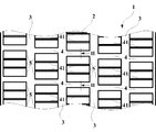
- Fig. 1 is a schematic view of a portion of a tread for a tire according to a first embodiment of the present invention
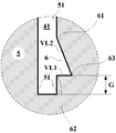
- Fig. 2 is a schematic cross sectional view taken along line II-II in Fig. 1
- Fig. 3 is an enlarged schematic view showing a portion indicated as III in Fig. 2
- Fig. 4 is a schematic cross sectional view according to a second embodiment of the present invention
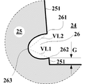
- Fig. 5 is an enlarged schematic view showing a portion indicated as V in Fig. 4
- Fig. 6 is a schematic cross sectional view according to a third embodiment of the present invention
- a tread 1 for a tire according to a first embodiment of the present invention will be described referring to Figs. 1, 2 and 3.
- Fig. 1 is a schematic view of a portion of a tread for a tire according to a first embodiment of the present invention.
- Fig.2 is a schematic cross sectional view taken along line II-II in Fig. 1.
- Fig. 3 is an enlarged schematic view showing a portion indicated as III in Fig. 2.
- the tread 1 is a tread for a tire having dimension 225/45R17 and comprises a contact face 2 intended to come into contact with the ground during rolling, and a plurality of main groove 3 extending generally in circumferential orientation that is top-bottom orientation in Fig. 1.
- the tread 1 also comprises a plurality of cuts 4, 41 opening to the contact face 2.
- the plurality of cuts 4 are lateral grooves and the plurality of cuts 41 are sipes, both extending in lateral orientation that is left-right orientation in Fig. 1 and substantially parallel one another.
- the plurality of cuts 4, 41 and the main groove 3 delimiting a plurality of contact elements 5.
- each the plurality of contact elements 5 having a plurality of lateral walls 51 facing to a cut 4, 41 among the plurality of cuts 4, 41.
- Each the plurality of lateral walls 51 creating an edge portion 52 at an intersection with the contact face 2.
- One lateral wall 51 among the plurality of lateral walls 51 forming a contact element 5 among the plurality of contact elements 5 being provided with a concavity 6 opening to the cut 41.
- one lateral wall 51 facing to the cut 41 is provided with the concavity 6, and another lateral wall 51 facing to the same cut 41 is provided without the concavity.
- no concavity is provided with any lateral wall facing to the cut 4.
- the concavity 6 extending on the lateral wall 51 of the contact element 5 in a direction the cut 41 is extending and over an entire width of the lateral wall 51 at a radial position where the concavity 6 being provided (not shown).
- the concavity 6 On a plane perpendicular to both the contact face 2 and the lateral wall 51 provided with the concavity 6, the concavity 6 having two concavity edge portions at an intersection with the lateral wall 51, an upper concavity edge portion 61 being located radially outward and a lower concavity edge portion 62 being radially distant from radially innermost of the lateral wall 51 provided with the concavity 6 with a distance G .
- the concavity 6 creating an innermost portion 63 the farthest from the lateral wall 51 in transverse direction on the plane toward another lateral wall 51 constituting the same contact element 5.
- the concavity 6 has a triangular shape consists of three apexes, the upper concavity edge portion 61, the lower concavity edge portion 62 and the innermost portion 63.
- the cut(s) 4 and the cut(s) 41 have the same depth H measured radially from the contact face 2.
- Two edge portions 52 of the same contact element 5 being distant in transverse direction on the plane with a distance B .
- the innermost portion 63 of the concavity 6 being transversely inward of the contact element 5 from the closest edge portion 52 with a distance D .
- a volume of the concavity 6 is at most equal to 5% of total volume of the contact element 5, and the distance D is in a range between 10% and 30% of the distance B .
- the depth H is 9.4mm
- the volume of the concavity 6 is 1.3% of total volume of the contact element 5
- the distance D is equal to 13.3% of the distance B .
- the upper concavity edge portion 61 locates at a position more than 50% of the depth H radially inward from the contact face 2.
- the innermost portion 63 locates at a position radially equal to the lower concavity edge portion 62.
- the distance G is at least equal to 0.1mm. In the present embodiment, the distance G is equal to 0.9mm.
- a radial distance between the upper concavity edge portion 61 and the lower concavity edge portion 62 is longer than the distance D .
- a ratio between the radial distance between the upper concavity edge portion and the lower concavity edge portion is set to be in a range between 50% and 180% of the distance D .
- a length of a virtual straight line VL1 connecting the lower concavity edge portion 62 and the innermost portion 63 is shorter than a length of a virtual straight line VL2 connecting the upper concavity edge portion 61 and the innermost portion 63.
- the contact element 5 can deform better for increasing a contact pressure around an edge portion 52 for digging into a snow covered surface, thus performance on wintry (or white) road is improved.
- the concavity 6 having two concavity edge portions at an intersection with the lateral wall 51, an upper concavity edge portion 61 being located radially outward and a lower concavity edge portion 62 being located radially inward, the lower concavity edge portion 62 being radially distant from radially innermost of the lateral wall 51 provided with the concavity 6 with a distance G , an infection point of the contact element 5 can be separated from radially innermost of the lateral wall 51, thus endurance performance of the contact element 5 can be maintained.
- the contact element 5 can deform reliably for increasing a contact pressure around an edge portion 52 for digging into a snow covered surface, thus performance on wintry (or white) road is improved.
- a volume of the concavity 6 is at most equal to 5% of total volume of the contact element 5, and the distance D is in a range between 10% and 30% of the distance B , degradation of a rigidity of the contact element 5 can be minimized or even ignorable, thus performance on normal (or black) road can be maintained.
- volume of the concavity 6 is more than 5% of total volume of the contact element 5, degradation of the rigidity of the contact element 5 becomes important and performance on normal (or black) road cannot be maintained.
- This volume of the concavity 6 is preferably more than or equal to 0.1%, more preferably more than or equal to 0.2% and still more preferably more than or equal to 0.3% of total volume of the contact element 5.
- this distance D is less than 10%, there is a risk that improvement of performance on wintry (or white) road by the concavity 6 is not satisfactory because the contact element 5 cannot deform well. If this distance D is more than 30%, there is a risk that degradation of the performance on normal (or black) road becomes non-negligible because the contact element 5 deforms too match.
- this distance D being in the range between 10% and 30% of the distance B , it is possible to achieve improvement of performance on wintry (or white) road while maintaining performance on normal (or black) road.
- the upper concavity edge portion 61 locates at a position more than 50% of the depth H radially inward from the contact face 2, it is possible to achieve improvement of performance on wintry (or white) road, and such the improvement lasts longer.
- the upper concavity edge portion 61 locates at a position less than 50% of the depth H radially inward from the contact face 2, there is a risk that improvement of performance on wintry (or white) road by the concavity 6 is not satisfactory because a volume of a portion on the contact element 5 possible to deform is not enough. Moreover such the portion cannot last long enough due to wear of the contact element 5.
- the innermost portion 63 locates at a position radially equal to or inward of the lower concavity edge portion 62, it is possible to maintain productivity for manufacturing the tread 1 provided with the concavity 6. On the other words, if the innermost portion 63 locates at a position radially outward of the lower concavity edge portion 62, there is a risk that productivity for manufacturing the tread 1 provided with the concavity 6 decreases due to demolding difficulty.
- a ratio between a radial distance between the upper concavity edge portion 61 and the lower concavity edge portion 62 is in a range between 50% and 180% of the distance D , it is possible to maintain productivity for manufacturing the tread 1 with the concavity 6 while improving performance on wintry (or white) road by the concavity 6.
- this ratio between the radial distance between the upper concavity edge portion 61 and the lower concavity edge portion 62 is less than 50% of the distance D , there is a risk that a portion provided on the cut 41 for creating the concavity 6 is damaged during manufacturing thus decreasing productivity for manufacturing the tread 1 with the concavity 6.
- this ratio between the radial distance between the upper concavity edge portion 61 and the lower concavity edge portion 62 is more than 180% of the distance D , there is a risk that improvement of performance on wintry (or white) road by the concavity 6 is not satisfactory because ability to deform the contact element 5 by the concavity 6 is limited geometrically.
- this ratio between the radial distance between the upper concavity edge portion 61 and the lower concavity edge portion 62 in the range between 50% and 180% of the distance D, it is possible to maintain productivity for manufacturing the tread 1 with the concavity 6 while improving performance on wintry (or white) road by the concavity.
- This ratio between the radial distance between the upper concavity edge portion 61 and the lower concavity edge portion 62 and the distance D is preferably in the range between 60% and 170%, more preferably in the range between 70% and 150% and still more preferably between 75% and 130%.
- a length of a virtual straight line VL1 connecting the lower concavity edge portion 62 and the innermost portion 63 is shorter than a length of a virtual straight line VL2 connecting the upper concavity edge portion 61 and the innermost portion 63, it is possible to maintain productivity for manufacturing the tread 1 provided with the concavity 6.
- the length of the virtual straight line VL1 connecting the lower concavity edge portion 62 and the innermost portion 63 is longer than the length of the virtual straight line VL2 connecting the upper concavity edge portion 61 and the innermost portion 63, there is a risk that productivity for manufacturing the tread 1 provided with the concavity 6 decreases due to demolding difficulty.
- the distance G is at least equal to 0.1mm, it is possible to maintain endurance performance of the contact element 5 by separating the infection point of the contact element 5 from radially innermost of the lateral wall 51, and simultaneously improvement of performance on wintry (or white) road lasts longer.
- This distance G is preferably at least equal to 0.2mm, more preferably at least equal to 0.5mm.
- the lateral wall 51 facing to the cut 4 may be provided with the concavity 6.
- a shape of the concavity 6 may be the same as the concavity 6 provided on the lateral wall 51 facing to the cut 41.
- a shape of the concavity 6 may be different among the concavity 6 provided.
- the contact element 5 may also be provided with the cut 41 without having the concavity 6 facing to the cut 41.
- a ratio between the depth H and the distance B may be better to set more than or equal to 0.58, preferably more than or equal to 0.6 for emphasizing the improvement provided with the concavity 6.
- FIG. 4 is a schematic cross sectional view according to a second embodiment of the present invention.
- Fig. 5 is an enlarged schematic view showing a portion indicated as V in Fig. 4.
- the tread 21 is provided with a plurality of cuts 24, 241 delimiting a plurality of contact elements 25, each the plurality of contact elements 25 having a plurality of lateral walls 251 facing to a cut 24, 241 among the plurality of cuts 24, 241.
- Each the plurality of lateral walls 251 creating an edge portion 252 at an intersection with a contact face 22.
- One lateral wall 251 among the plurality of lateral walls 251 forming a contact element 25 among the plurality of contact elements 25 being provided with a concavity 26 opening to the cut 24.
- one lateral wall 251 facing to the cut 24 is provided with the concavity 26, and another lateral wall 251 facing to the same cut 24 is provided without the concavity.
- the lateral wall 251 facing to the cut 24 is extending at an angle against radial orientation as to decrease a distance between two opposed lateral walls 251 facing to the same cut 24 toward radially inwardly. Contrary the lateral wall 251 facing to the cut 241 is extending in radial orientation. A depth H of the cut 24 is deeper than a depth H of the cut 241.
- the concavity 26 On a plane perpendicular to both the contact face 22 and the lateral wall 251 provided with the concavity 26, the concavity 26 having two concavity edge portions at an intersection with the lateral wall 251, an upper concavity edge portion 261 being located radially outward and a lower concavity edge portion 262 being radially distant from radially innermost of the lateral wall 251 provided with the concavity 26 with a distance G .
- the concavity 26 creating an innermost portion 263 the farthest from the lateral wall 251 in transverse direction on the plane toward another lateral wall 251 constituting the same contact element 25.
- the concavity 26 has an oval semicircular shape.
- a length of a virtual straight line VL1 connecting the lower concavity edge portion 262 and the innermost portion 263 is shorter than a length of a virtual straight line VL2 connecting the upper concavity edge portion 261 and the innermost 263.
- a length of a virtual straight line VL1 connecting the lower concavity edge portion 262 and the innermost portion 263 is shorter than a length of a virtual straight line VL2 connecting the upper concavity edge portion 261 and the innermost portion 263, it is possible to maintain productivity for manufacturing the tread 21 provided with the concavity 26.
- the length of the virtual straight line VL1 connecting the lower concavity edge portion 262 and the innermost portion 263 is longer than the length of the virtual straight line VL2 connecting the upper concavity edge portion 261 and the innermost portion 263, there is a risk that productivity for manufacturing the tread 21 provided with the concavity 26 decreases due to demolding difficulty.
- the lateral wall 251 facing to the cut 241 may be provided with the concavity 26.
- a shape of the concavity 26 may be the same as the concavity 26 provided on the lateral wall 251 facing to the cut 24.
- a shape of the concavity 26 may be different among the concavity 26 provided.
- the contact element 25 may also be provided with the cut 24 and/or 241 without having the concavity 26 facing to the cut 24 or 241.
- Fig. 6 is a schematic cross sectional view according to a third embodiment of the present invention.
- the tread 31 is provided with a plurality of cuts 34, 341 delimiting a plurality of contact elements 35, each the plurality of contact elements 35 having a plurality of lateral walls 351 facing to a cut 34, 341 among the plurality of cuts 34, 341.
- Each the plurality of lateral walls 351 creating an edge portion 352 at an intersection with a contact face 32.
- One lateral wall 351 among the plurality of lateral walls 351 forming a contact element 35 among the plurality of contact elements 35 being provided with a concavity 36 opening to the cut 34.
- one lateral wall 351 facing to the cut 34 is provided with the concavity 36, and another lateral wall 351 facing to the same cut 34 is provided without the concavity.
- One lateral wall 351 among the plurality of lateral walls 351 forming a contact element 35 among the plurality of contact elements 35 being provided with a concavity 36 opening to the cut 341.
- one lateral wall 351 facing to the cut 341 is provided with the concavity 36
- another lateral wall 351 facing to the same cut 341 is provided with another concavity 36 having a different shape and at a different radial position.
- the concavity 36 extending on the lateral wall 351 of the contact element 35 in a direction the cut 34 is extending and over an entire width of the lateral wall 351 at a radial position where the concavity 36 being provided (not shown).
- the lateral wall 351 facing to the cut 34 is extending at an angle against radial orientation as to decrease a distance between two opposed lateral walls 351 facing to the same cut 34 toward radially inwardly. Contrary the lateral wall 351 facing to the cut 341 is extending in radial orientation.
- a depth H of the cut 34 (not shown) is the same as a depth H of the cut 341 (not shown).
- the concavity 36 On a plane perpendicular to both the contact face 32 and the lateral wall 351 provided with the concavity 36, the concavity 36 having two concavity edge portions at an intersection with the lateral wall 351, an upper concavity edge portion 361 being located radially outward and a lower concavity edge portion 362 being radially distant from radially innermost of the lateral wall 351 provided with the concavity 36 with a distance G (not shown).
- the concavity 36 creating an innermost portion 363 the farthest from the lateral wall 351 in transverse direction on the plane toward another lateral wall 351 constituting the same contact element 35.
- the concavity 36 has a triangular shape consists of three apexes, the upper concavity edge portion 361, the lower concavity edge portion 362 and the innermost portion 363.
- the concavity 36 facing to the cut 341 has a right triangular shape
- the another concavity 36 facing to the same cut 341 has the triangular shape creating an obtuse angle with the innermost portion 363
- the concavity 36 facing to the cut 34 has the triangular shape creating an acute angle with the innermost portion 363.
- the innermost portion 363 locates at a position radially inward of the lower concavity edge portion 362.
- the innermost portion 363 locates at a position radially equal to or inward of the lower concavity edge portion 362, it is possible to maintain productivity for manufacturing the tread 31 provided with the concavity 36. On the other words, if the innermost portion 363 locates at a position radially outward of the lower concavity edge portion 362, there is a risk that productivity for manufacturing the tread 31 provided with the concavity 36 decreases due to demolding difficulty.
- the two lateral walls 351 constituting the same contact element 35 are provided with the concavity 36, it is possible to increase a degree of freedom of design of the tread 31 provided with the concavity 36 and to improve the performance of such the tread 31 in various situations (for example, for braking and for acceleration).
- the Example 1 was a block sample as described in the above first embodiment having the distance B between two edge portions equals to 6.35mm and the ratio between the distance D and the distance B ( D / B ) equals to 16%
- the Example 2 was also a block sample as described in the above first embodiment having different dimensions compared to the Example 1, the distance B between two edge portions equals to 8.6mm and the ratio between the distance D and the distance B ( D / B ) equals to 12%.
- the Reference 1 was a block sample having the same dimensions as the Example 1 but without the concavity
- the Reference 2 was a block sample having the same dimensions as the Example 2 but without the concavity.
- the Comparative Example 1 was a block sample having the same configuration as the Reference 1 with the distance B equals to 5.0mm
- the Comparative Example 1 was a block sample having the same configuration as the Example 1 with the ratio between the distance D and the distance B ( D / B ) equals to 31%
- the Comparative Example 3 was a block sample having the same configuration as the Reference 2 with the distance B equals to 6.35mm.
- the depth H of the cut was 9.4mm for all the Examples, References and Comparative Examples. All the Examples, References and Comparative Examples were made of the same rubber material.
- the friction coefficient measurements on snow were carried out with the above Examples, References and Comparative Examples sliding at a given condition (a displacement: 0 to 0.03 m, a speed: 0 to 0.5 m/s, and an acceleration: 5 m/s2) over a hard pack snow track, set at about -10°C with a CTI penetrometer reading of about 90 in accordance with Standard ASTM F1805, with an imposed normal stress (about 300 kPa).
- the forces generated in a direction of travel (Fx) of each of the Examples, References and Comparative Examples and in another direction perpendicular to the travel (Fz) were measured.
- the Fx/Fz ratio determines the friction coefficient of each of the Examples, References and Comparative Examples on the snow.
- results are shown in table 1 and in table 2.
- results are represented by an index of 100 for Reference, higher the number indicates better the performance.
- the force generated in a direction of travel (Fx) of each of the Examples, References and Comparative Examples while applying 1mm of a shearing force in the direction of travel with an imposed normal stress (about 300 kPa) were measured as a representative of block rigidity.
- results are also shown in table 1 and in table 2.
- results are represented by an index of 100 for Reference, higher the number indicates better the performance. Within 10 points difference on this comparison could be considered as equivalent.
Landscapes
- Engineering & Computer Science (AREA)
- Mechanical Engineering (AREA)
- Tires In General (AREA)
Abstract
A tread being provided with a plurality of contact elements (5) having a plurality of lateral walls (51) facing to a cut (4, 41), at least one of a lateral wall (51) being provided with a concavity (6) extending over an entire width of the lateral wall (51), the concavity having two concavity edge portions (61, 62) at an intersection with the lateral wall radially distant from radially innermost of the lateral wall (51) with a distance G, on a plane perpendicular to both the contact face (2) and the lateral wall (51), the concavity (6) creating an innermost portion (63) the farthest from the lateral wall in transverse direction, two edge portions (52) being distant in transverse direction with a distance B, the innermost portion (63) being transversely distant from the closest edge portion (52) with a distance D, at a new state, a volume of the concavity (6) is at most equal to 5% of total volume of the contact element (5), the distance D is between 10% and 30% of the distance B, and a length of a virtual straight line connecting a lower concavity edge portion (62) and the innermost portion (63) is shorter than a length of a virtual straight line connecting an upper concavity edge portion (61) and the innermost portion (63).
Description
The present invention relates to a tread for a tire, in particular to a tread for a tire provided with a concavity possible to provide improvement on wintry (or white) road performance while maintaining satisfactory level of normal (or black) road performance.
In recent years, a tire so-called “all-season” tire which has capability to drive on wintry (or white) road, for example snow covered road while maintaining high speed driving capability on normal (or black) road is beginning to popularize.
Also to a tire so-called “studless” tire which is suitable for driving on ice covered and/or snow covered wintry (or white) road, there is a desire to increase performance on normal (or black) road that is not covered by ice nor snow while still improving performance on wintry (or white) road.
In order to increase performance on wintry (or white) road especially snow performance, it is known to reduce a distance between rubber elements of a tread of the tire delimited by a groove and/or an incision, or to use a soft rubber composition constituting the tread of the tire, or both at the same time is effective. It is also known that such the way impacts negatively performance on normal (or black) road.
WO2014/102039 discloses a tire having a depression (a concavity) delimited by a cover layer made of a material having an elastic modulus higher than an elastic modulus of a rubber material of which the tread being made.
WO2015/128106 discloses a tire having an incision provided with a depression (a concavity) on an incision wall being surrounded on an edge side at least 2mm of the incision wall.
The above arrangements intend to increase a rigidity of a tread provided with the depression to achieve satisfactory normal (or black) road performance.
However, with the above arrangements, the rigidity of the tread becomes too high even provided with the depression. Therefore, it is difficult to obtain satisfactory wintry (or white) road performance simultaneously with satisfactory normal (or black) road performance. Moreover with the arrangement disclosed in WO2014/102039, complex process for placing the cover layer is required thus degrading productivity for manufacturing such the tire.
JP2012-106707 discloses a tire having a concave section being arranged on a wall face at one lug groove side as to open to both wall faces to a circumferential main groove.
However, with the above arrangement, degradation of a rigidity of a block provided with the concave section becomes non negligible which impacts strongly on normal (or black) road performance. Therefore, it is difficult to obtain satisfactory normal (or black) road performance simultaneously with satisfactory wintry (or white) road performance.
Therefore, there is a need for a tread for a tire which improves wintry (or white) road performance simultaneously with satisfactory normal (or black) road performance
Definitions:
A “radial direction/orientation” is a direction/orientation perpendicular to axis of rotation of the tire. This direction/orientation corresponds to thickness orientation of the tread.
An “axial direction/orientation” is a direction/orientation parallel to axis of rotation of the tire.
A “circumferential direction/orientation” is a direction/orientation which is tangential to any circle centered on axis of rotation. This direction/orientation is perpendicular to both the axial direction/orientation and the radial direction/orientation.
A “tire” means all types of elastic tire whether or not subjected to an internal pressure.
A “tread” of a tire means a quantity of rubber material bounded by lateral surfaces and by two main surfaces one of which is intended to come into contact with ground when the tire is rolling.
A “cut” is either a groove or a sipe. More specifically, a cut corresponds to the space delimited by the walls of material that face one another and are distant from one another by a non-zero distance.
A “groove” is a space between two rubber faces/sidewalls which do not contact between themselves under usual rolling condition connected by another rubber face/ bottom. A groove has a width and a depth.
A “sipe”, also referred to as an “incision”, is a narrow cutout formed toward radially inwardly from a surface of a tread made by, for example a thin blade having a shape like a knife blade. A width of the incision at the surface of the tread is narrower than a groove, for example less than or equal to 2.0mm. This incision may, different from the groove, be partly or completely closed when such the incision is in a contact patch and under usual rolling condition.
It is thus an object of the invention to provide a tread for a tire provided with a concavity, such the tread can provide improvement of wintry (or white) road performance while maintaining satisfactory level of normal (or black) road performance.
The present invention provides a tread for a tire having a contact face intended to come into contact with ground during rolling, the tread being provided with at least one main groove, a plurality of cuts opening to the contact face extending as to crossing with the main groove and substantially parallel one another, the plurality of cuts and the main groove delimiting a plurality of contact elements, each the plurality of contact elements having a plurality of lateral walls facing to a cut among the plurality of cuts and/or the main groove, each the plurality of lateral walls creating an edge portion at an intersection with the contact face, at least one of a lateral wall among the plurality of lateral walls forming a contact element among the plurality of contact elements being provided with a concavity opening to the cut and/or to the main groove, the concavity extending on the lateral wall of the contact element in a direction the cut or the main groove is extending and over an entire width of the lateral wall at a radial position where the concavity being provided, on a plane perpendicular to both the contact face and the lateral wall provided with the concavity, the concavity having two concavity edge portions at an intersection with the lateral wall, an upper concavity edge portion being located radially outward and a lower concavity edge portion being located radially inward, the lower concavity edge portion being radially distant from radially innermost of the lateral wall provided with the concavity with a distance G, the concavity creating an innermost portion the farthest from the lateral wall in transverse direction on the plane, the cut having a depth H, two edge portions being distant in transverse direction on the plane with a distance B, the innermost portion of the concavity being transversely inward of the contact element from the closest edge portion with a distance D, at a new state, a volume of the concavity is at most equal to 5% of total volume of the contact element, and the distance D is in a range between 10% and 30% of the distance B, and a length of a virtual straight line connecting the lower concavity edge portion and the innermost portion is shorter than a length of a virtual straight line connecting the upper concavity edge portion and the innermost portion.
This arrangement provides improvement of wintry (or white) road performance while maintaining satisfactory level of normal (or black) road performance.
Since at least one of a lateral wall forming a contact element being provided with a concavity opening to a cut and/or to a main groove and extending on the lateral wall in a direction the cut or the main groove is extending and over an entire width of the lateral wall at a radial position where the concavity being provided, the contact element can deform better for increasing a contact pressure around an edge portion for digging into a snow covered surface, thus performance on wintry (or white) road is improved.
Since the concavity having two concavity edge portions at an intersection with the lateral wall, an upper concavity edge portion being located radially outward and a lower concavity edge portion being located radially inward, the lower concavity edge portion being radially distant from radially innermost of the lateral wall provided with the concavity with a distance G, an infection point of the contact element can be separated from radially innermost of the lateral wall, thus endurance performance of the contact element can be maintained.
Since the concavity creating an innermost portion the farthest from the lateral wall in transverse direction on the plane, the cut having a depth H, two edge portions being distant in transverse direction on the plane with a distance B, the innermost portion of the concavity being transversely inwardly distant from the closest edge portion with a distance D on a plane perpendicular to both the contact face and the lateral wall provided with the concavity, the contact element can deform reliably for increasing a contact pressure around an edge portion for digging into a snow covered surface, thus performance on wintry (or white) road is improved.
Since a volume of the concavity is at most equal to 5% of total volume of the contact element, and the distance D is in a range between 10% and 30% of the distance B, degradation of a rigidity of the contact element can be minimized or even ignorable, thus performance on normal (or black) road can be maintained.
If the volume of the concavity is more than 5% of total volume of the contact element, degradation of the rigidity of the contact element becomes important and performance on normal (or black) road cannot be maintained.
This volume of the concavity is preferably more than or equal to 0.1%, more preferably more than or equal to 0.2% and still more preferably more than or equal to 0.3% of total volume of the contact element.
If this distance D is less than 10%, there is a risk that improvement of performance on wintry (or white) road by the concavity is not satisfactory because the contact element cannot deform well. If this distance D is more than 30%, there is a risk that degradation of the performance on normal (or black) road becomes non-negligible because the contact element deforms too match. By setting this distance D being in the range between 10% and 30% of the distance B, it is possible to achieve improvement of performance on wintry (or white) road while maintaining performance on normal (or black) road.
Since a length of a virtual straight line connecting the lower concavity edge portion and the innermost portion is shorter than a length of a virtual straight line connecting the upper concavity edge portion and the innermost portion, it is possible to maintain productivity for manufacturing the tread provided with the concavity. On the other words, if the length of the virtual straight line connecting the lower concavity edge portion and the innermost portion is longer than the length of the virtual straight line connecting the upper concavity edge portion and the innermost portion, there is a risk that productivity for manufacturing the tread provided with the concavity decreases due to demolding difficulty.
In another preferred embodiment, the upper concavity edge portion locates at a position more than 50% of the depth H radially inward from the contact face.
If the upper concavity edge portion locates at a position less than 50% of the depth H radially inward from the contact face, there is a risk that improvement of performance on wintry (or white) road by the concavity is not satisfactory because a volume of a portion on the contact element possible to deform is not enough. Moreover such the portion cannot last long enough due to wear of the contact element. By setting this position of the upper concavity edge portion more than 50% of the depth H radially inward from the contact face, it is possible to achieve improvement of performance on wintry (or white) road, and such the improvement lasts longer.
In another preferred embodiment, the innermost portion locates at a position radially equal to or inward of the lower concavity edge portion.
According to this arrangement, it is possible to maintain productivity for manufacturing the tread provided with the concavity. On the other words, if the innermost portion locates at a position radially outward of the lower concavity edge portion, there is a risk that productivity for manufacturing the tread provided with the concavity decreases due to demolding difficulty.
In another preferred embodiment, a ratio between a radial distance between the upper concavity edge portion and the lower concavity edge portion is in a range between 50% and 180% of the distance D.
According to this arrangement, it is possible to maintain productivity for manufacturing the tread with the concavity while improving performance on wintry (or white) road by the concavity. On the other words, if this ratio between the radial distance between the upper concavity edge portion and the lower concavity edge portion is less than 50% of the distance D, there is a risk that a portion provided on the cut for creating the concavity is damaged during manufacturing thus decreasing productivity for manufacturing the tread with the concavity. If this ratio between the radial distance between the upper concavity edge portion and the lower concavity edge portion is more than 180% of the distance D, there is a risk that improvement of performance on wintry (or white) road by the concavity is not satisfactory because ability to deform the contact element by the concavity is limited geometrically. By setting this ratio between the radial distance between the upper concavity edge portion and the lower concavity edge portion in the range between 50% and 180% of the distance D, it is possible to maintain productivity for manufacturing the tread with the concavity while improving performance on wintry (or white) road by the concavity.
This ratio between the radial distance between the upper concavity edge portion and the lower concavity edge portion and the distance D is preferably in the range between 60% and 170%, more preferably in the range between 70% and 150% and still more preferably between 75% and 130%.
In another preferred embodiment, the distance G is at least equal to 0.1mm.
According to this arrangement, it is possible to maintain endurance performance of the contact element by separating the infection point of the contact element from radially innermost of the lateral wall, and simultaneously improvement of performance on wintry (or white) road lasts longer. This distance G is preferably at least equal to 0.2mm, more preferably at least equal to 0.5mm.
In another preferred embodiment, the two lateral walls constituting the same contact element are provided with the concavity.
According to this arrangement, it is possible to increase a degree of freedom of design of the tread provided with the concavity and to improve the performance of such the tread in various situations (for example, for braking and for acceleration).
According to the arrangements described above, it is possible to provide a tread for a tire comprising a concavity, such the tread can provide improvement of wintry (or white) road performance while maintaining satisfactory level of normal (or black) road performance.
Other characteristics and advantages of the invention arise from the description made hereafter in reference to the annexed drawings which show, as nonrestrictive examples, the embodiment of the invention.
In these drawings:
Fig. 1 is a schematic view of a portion of a tread for a tire according to a first embodiment of the present invention;
Fig. 2 is a schematic cross sectional view taken along line II-II in Fig. 1;
Fig. 3 is an enlarged schematic view showing a portion indicated as III in Fig. 2;
Fig. 4 is a schematic cross sectional view according to a second embodiment of the present invention;
Fig. 5 is an enlarged schematic view showing a portion indicated as V in Fig. 4;
Fig. 6 is a schematic cross sectional view according to a third embodiment of the present invention;
Preferred embodiments of the present invention will be described below referring to the drawings.
A tread 1 for a tire according to a first embodiment of the present invention will be described referring to Figs. 1, 2 and 3.
Fig. 1 is a schematic view of a portion of a tread for a tire according to a first embodiment of the present invention. Fig.2 is a schematic cross sectional view taken along line II-II in Fig. 1. Fig. 3 is an enlarged schematic view showing a portion indicated as III in Fig. 2.
The tread 1 is a tread for a tire having dimension 225/45R17 and comprises a contact face 2 intended to come into contact with the ground during rolling, and a plurality of main groove 3 extending generally in circumferential orientation that is top-bottom orientation in Fig. 1. The tread 1 also comprises a plurality of cuts 4, 41 opening to the contact face 2. In this Fig. 1, the plurality of cuts 4 are lateral grooves and the plurality of cuts 41 are sipes, both extending in lateral orientation that is left-right orientation in Fig. 1 and substantially parallel one another. The plurality of cuts 4, 41 and the main groove 3 delimiting a plurality of contact elements 5.
As shown in Fig. 2, each the plurality of contact elements 5 having a plurality of lateral walls 51 facing to a cut 4, 41 among the plurality of cuts 4, 41. Each the plurality of lateral walls 51 creating an edge portion 52 at an intersection with the contact face 2. One lateral wall 51 among the plurality of lateral walls 51 forming a contact element 5 among the plurality of contact elements 5 being provided with a concavity 6 opening to the cut 41. In view of the cut 41, one lateral wall 51 facing to the cut 41 is provided with the concavity 6, and another lateral wall 51 facing to the same cut 41 is provided without the concavity. Contrary, no concavity is provided with any lateral wall facing to the cut 4. The concavity 6 extending on the lateral wall 51 of the contact element 5 in a direction the cut 41 is extending and over an entire width of the lateral wall 51 at a radial position where the concavity 6 being provided (not shown).
On a plane perpendicular to both the contact face 2 and the lateral wall 51 provided with the concavity 6, the concavity 6 having two concavity edge portions at an intersection with the lateral wall 51, an upper concavity edge portion 61 being located radially outward and a lower concavity edge portion 62 being radially distant from radially innermost of the lateral wall 51 provided with the concavity 6 with a distance G. The concavity 6 creating an innermost portion 63 the farthest from the lateral wall 51 in transverse direction on the plane toward another lateral wall 51 constituting the same contact element 5. The concavity 6 has a triangular shape consists of three apexes, the upper concavity edge portion 61, the lower concavity edge portion 62 and the innermost portion 63.
The cut(s) 4 and the cut(s) 41 have the same depth H measured radially from the contact face 2. Two edge portions 52 of the same contact element 5 being distant in transverse direction on the plane with a distance B. The innermost portion 63 of the concavity 6 being transversely inward of the contact element 5 from the closest edge portion 52 with a distance D. When the tread 1 is at a new state, a volume of the concavity 6 is at most equal to 5% of total volume of the contact element 5, and the distance D is in a range between 10% and 30% of the distance B. In the present embodiment, the depth H is 9.4mm, the volume of the concavity 6 is 1.3% of total volume of the contact element 5, and the distance D is equal to 13.3% of the distance B.
The upper concavity edge portion 61 locates at a position more than 50% of the depth H radially inward from the contact face 2. The innermost portion 63 locates at a position radially equal to the lower concavity edge portion 62. The distance G is at least equal to 0.1mm. In the present embodiment, the distance G is equal to 0.9mm.
A radial distance between the upper concavity edge portion 61 and the lower concavity edge portion 62 is longer than the distance D. A ratio between the radial distance between the upper concavity edge portion and the lower concavity edge portion is set to be in a range between 50% and 180% of the distance D.
As shown in Fig. 3, a length of a virtual straight line VL1 connecting the lower concavity edge portion 62 and the innermost portion 63 is shorter than a length of a virtual straight line VL2 connecting the upper concavity edge portion 61 and the innermost portion 63.
Since at least one of a lateral wall 51 forming a contact element 5 being provided with a concavity 6 opening to a cut 4, 41 and/or to a main groove 3 and extending on the lateral wall 51 in a direction the cut 4, 41 or the main groove 3 is extending and over an entire width of the lateral wall 51 at a radial position where the concavity 6 being provided, the contact element 5 can deform better for increasing a contact pressure around an edge portion 52 for digging into a snow covered surface, thus performance on wintry (or white) road is improved.
Since the concavity 6 having two concavity edge portions at an intersection with the lateral wall 51, an upper concavity edge portion 61 being located radially outward and a lower concavity edge portion 62 being located radially inward, the lower concavity edge portion 62 being radially distant from radially innermost of the lateral wall 51 provided with the concavity 6 with a distance G, an infection point of the contact element 5 can be separated from radially innermost of the lateral wall 51, thus endurance performance of the contact element 5 can be maintained.
Since the concavity 6 creating an innermost portion 63 the farthest from the lateral wall 51 in transverse direction on the plane, the cut 4, 41 having a depth H, two edge portions 52 being distant in transverse direction on the plane with a distance B, the innermost portion 63 of the concavity 6 being transversely inwardly distant from the closest edge portion 52 with a distance D on a plane perpendicular to both the contact face 2 and the lateral wall 51 provided with the concavity 6, the contact element 5 can deform reliably for increasing a contact pressure around an edge portion 52 for digging into a snow covered surface, thus performance on wintry (or white) road is improved.
Since a volume of the concavity 6 is at most equal to 5% of total volume of the contact element 5, and the distance D is in a range between 10% and 30% of the distance B, degradation of a rigidity of the contact element 5 can be minimized or even ignorable, thus performance on normal (or black) road can be maintained.
If the volume of the concavity 6 is more than 5% of total volume of the contact element 5, degradation of the rigidity of the contact element 5 becomes important and performance on normal (or black) road cannot be maintained.
This volume of the concavity 6 is preferably more than or equal to 0.1%, more preferably more than or equal to 0.2% and still more preferably more than or equal to 0.3% of total volume of the contact element 5.
If this distance D is less than 10%, there is a risk that improvement of performance on wintry (or white) road by the concavity 6 is not satisfactory because the contact element 5 cannot deform well. If this distance D is more than 30%, there is a risk that degradation of the performance on normal (or black) road becomes non-negligible because the contact element 5 deforms too match. By setting this distance D being in the range between 10% and 30% of the distance B, it is possible to achieve improvement of performance on wintry (or white) road while maintaining performance on normal (or black) road.
Since the upper concavity edge portion 61 locates at a position more than 50% of the depth H radially inward from the contact face 2, it is possible to achieve improvement of performance on wintry (or white) road, and such the improvement lasts longer.
If the upper concavity edge portion 61 locates at a position less than 50% of the depth H radially inward from the contact face 2, there is a risk that improvement of performance on wintry (or white) road by the concavity 6 is not satisfactory because a volume of a portion on the contact element 5 possible to deform is not enough. Moreover such the portion cannot last long enough due to wear of the contact element 5.
Since the innermost portion 63 locates at a position radially equal to or inward of the lower concavity edge portion 62, it is possible to maintain productivity for manufacturing the tread 1 provided with the concavity 6. On the other words, if the innermost portion 63 locates at a position radially outward of the lower concavity edge portion 62, there is a risk that productivity for manufacturing the tread 1 provided with the concavity 6 decreases due to demolding difficulty.
Since a ratio between a radial distance between the upper concavity edge portion 61 and the lower concavity edge portion 62 is in a range between 50% and 180% of the distance D, it is possible to maintain productivity for manufacturing the tread 1 with the concavity 6 while improving performance on wintry (or white) road by the concavity 6. On the other words, if this ratio between the radial distance between the upper concavity edge portion 61 and the lower concavity edge portion 62 is less than 50% of the distance D, there is a risk that a portion provided on the cut 41 for creating the concavity 6 is damaged during manufacturing thus decreasing productivity for manufacturing the tread 1 with the concavity 6. If this ratio between the radial distance between the upper concavity edge portion 61 and the lower concavity edge portion 62 is more than 180% of the distance D, there is a risk that improvement of performance on wintry (or white) road by the concavity 6 is not satisfactory because ability to deform the contact element 5 by the concavity 6 is limited geometrically. By setting this ratio between the radial distance between the upper concavity edge portion 61 and the lower concavity edge portion 62 in the range between 50% and 180% of the distance D, it is possible to maintain productivity for manufacturing the tread 1 with the concavity 6 while improving performance on wintry (or white) road by the concavity.
This ratio between the radial distance between the upper concavity edge portion 61 and the lower concavity edge portion 62 and the distance D is preferably in the range between 60% and 170%, more preferably in the range between 70% and 150% and still more preferably between 75% and 130%.
Since a length of a virtual straight line VL1 connecting the lower concavity edge portion 62 and the innermost portion 63 is shorter than a length of a virtual straight line VL2 connecting the upper concavity edge portion 61 and the innermost portion 63, it is possible to maintain productivity for manufacturing the tread 1 provided with the concavity 6. On the other words, if the length of the virtual straight line VL1 connecting the lower concavity edge portion 62 and the innermost portion 63 is longer than the length of the virtual straight line VL2 connecting the upper concavity edge portion 61 and the innermost portion 63, there is a risk that productivity for manufacturing the tread 1 provided with the concavity 6 decreases due to demolding difficulty.
Since the distance G is at least equal to 0.1mm, it is possible to maintain endurance performance of the contact element 5 by separating the infection point of the contact element 5 from radially innermost of the lateral wall 51, and simultaneously improvement of performance on wintry (or white) road lasts longer. This distance G is preferably at least equal to 0.2mm, more preferably at least equal to 0.5mm.
The lateral wall 51 facing to the cut 4 may be provided with the concavity 6. In such the case a shape of the concavity 6 may be the same as the concavity 6 provided on the lateral wall 51 facing to the cut 41. A shape of the concavity 6 may be different among the concavity 6 provided. The contact element 5 may also be provided with the cut 41 without having the concavity 6 facing to the cut 41.
A ratio between the depth H and the distance B (H/B) may be better to set more than or equal to 0.58, preferably more than or equal to 0.6 for emphasizing the improvement provided with the concavity 6.
A tread 21 for a tire according to a second embodiment of the present invention will be described referring to Fig. 4 and Fig. 5. Fig. 4 is a schematic cross sectional view according to a second embodiment of the present invention. Fig. 5 is an enlarged schematic view showing a portion indicated as V in Fig. 4.
In the second embodiment, the tread 21 is provided with a plurality of cuts 24, 241 delimiting a plurality of contact elements 25, each the plurality of contact elements 25 having a plurality of lateral walls 251 facing to a cut 24, 241 among the plurality of cuts 24, 241. Each the plurality of lateral walls 251 creating an edge portion 252 at an intersection with a contact face 22. One lateral wall 251 among the plurality of lateral walls 251 forming a contact element 25 among the plurality of contact elements 25 being provided with a concavity 26 opening to the cut 24. In view of the cut 24, one lateral wall 251 facing to the cut 24 is provided with the concavity 26, and another lateral wall 251 facing to the same cut 24 is provided without the concavity. Contrary, no concavity is provided with any lateral wall facing to the cut 241. The concavity 26 extending on the lateral wall 251 of the contact element 25 in a direction the cut 24 is extending and over an entire width of the lateral wall 251 at a radial position where the concavity 26 being provided (not shown).
The lateral wall 251 facing to the cut 24 is extending at an angle against radial orientation as to decrease a distance between two opposed lateral walls 251 facing to the same cut 24 toward radially inwardly. Contrary the lateral wall 251 facing to the cut 241 is extending in radial orientation. A depth H of the cut 24 is deeper than a depth H of the cut 241.
On a plane perpendicular to both the contact face 22 and the lateral wall 251 provided with the concavity 26, the concavity 26 having two concavity edge portions at an intersection with the lateral wall 251, an upper concavity edge portion 261 being located radially outward and a lower concavity edge portion 262 being radially distant from radially innermost of the lateral wall 251 provided with the concavity 26 with a distance G. The concavity 26 creating an innermost portion 263 the farthest from the lateral wall 251 in transverse direction on the plane toward another lateral wall 251 constituting the same contact element 25. The concavity 26 has an oval semicircular shape.
A length of a virtual straight line VL1 connecting the lower concavity edge portion 262 and the innermost portion 263 is shorter than a length of a virtual straight line VL2 connecting the upper concavity edge portion 261 and the innermost 263.
Since a length of a virtual straight line VL1 connecting the lower concavity edge portion 262 and the innermost portion 263 is shorter than a length of a virtual straight line VL2 connecting the upper concavity edge portion 261 and the innermost portion 263, it is possible to maintain productivity for manufacturing the tread 21 provided with the concavity 26. On the other words, if the length of the virtual straight line VL1 connecting the lower concavity edge portion 262 and the innermost portion 263 is longer than the length of the virtual straight line VL2 connecting the upper concavity edge portion 261 and the innermost portion 263, there is a risk that productivity for manufacturing the tread 21 provided with the concavity 26 decreases due to demolding difficulty.
The lateral wall 251 facing to the cut 241 may be provided with the concavity 26. In such the case a shape of the concavity 26 may be the same as the concavity 26 provided on the lateral wall 251 facing to the cut 24. A shape of the concavity 26 may be different among the concavity 26 provided. The contact element 25 may also be provided with the cut 24 and/or 241 without having the concavity 26 facing to the cut 24 or 241.
A tread 31 for a tire according to a third embodiment of the present invention will be described referring to Fig. 6. Fig. 6 is a schematic cross sectional view according to a third embodiment of the present invention.
In the third embodiment, the tread 31 is provided with a plurality of cuts 34, 341 delimiting a plurality of contact elements 35, each the plurality of contact elements 35 having a plurality of lateral walls 351 facing to a cut 34, 341 among the plurality of cuts 34, 341. Each the plurality of lateral walls 351 creating an edge portion 352 at an intersection with a contact face 32. One lateral wall 351 among the plurality of lateral walls 351 forming a contact element 35 among the plurality of contact elements 35 being provided with a concavity 36 opening to the cut 34. In view of the cut 34, one lateral wall 351 facing to the cut 34 is provided with the concavity 36, and another lateral wall 351 facing to the same cut 34 is provided without the concavity. One lateral wall 351 among the plurality of lateral walls 351 forming a contact element 35 among the plurality of contact elements 35 being provided with a concavity 36 opening to the cut 341. In view of the cut 341, one lateral wall 351 facing to the cut 341 is provided with the concavity 36, and another lateral wall 351 facing to the same cut 341 is provided with another concavity 36 having a different shape and at a different radial position. The concavity 36 extending on the lateral wall 351 of the contact element 35 in a direction the cut 34 is extending and over an entire width of the lateral wall 351 at a radial position where the concavity 36 being provided (not shown).
The lateral wall 351 facing to the cut 34 is extending at an angle against radial orientation as to decrease a distance between two opposed lateral walls 351 facing to the same cut 34 toward radially inwardly. Contrary the lateral wall 351 facing to the cut 341 is extending in radial orientation. A depth H of the cut 34 (not shown) is the same as a depth H of the cut 341 (not shown).
On a plane perpendicular to both the contact face 32 and the lateral wall 351 provided with the concavity 36, the concavity 36 having two concavity edge portions at an intersection with the lateral wall 351, an upper concavity edge portion 361 being located radially outward and a lower concavity edge portion 362 being radially distant from radially innermost of the lateral wall 351 provided with the concavity 36 with a distance G (not shown). The concavity 36 creating an innermost portion 363 the farthest from the lateral wall 351 in transverse direction on the plane toward another lateral wall 351 constituting the same contact element 35. The concavity 36 has a triangular shape consists of three apexes, the upper concavity edge portion 361, the lower concavity edge portion 362 and the innermost portion 363. The concavity 36 facing to the cut 341 has a right triangular shape, the another concavity 36 facing to the same cut 341 has the triangular shape creating an obtuse angle with the innermost portion 363, the concavity 36 facing to the cut 34 has the triangular shape creating an acute angle with the innermost portion 363. With the concavity 36 facing to the cut 34, the innermost portion 363 locates at a position radially inward of the lower concavity edge portion 362.
Since the innermost portion 363 locates at a position radially equal to or inward of the lower concavity edge portion 362, it is possible to maintain productivity for manufacturing the tread 31 provided with the concavity 36. On the other words, if the innermost portion 363 locates at a position radially outward of the lower concavity edge portion 362, there is a risk that productivity for manufacturing the tread 31 provided with the concavity 36 decreases due to demolding difficulty.
Since the two lateral walls 351 constituting the same contact element 35 are provided with the concavity 36, it is possible to increase a degree of freedom of design of the tread 31 provided with the concavity 36 and to improve the performance of such the tread 31 in various situations (for example, for braking and for acceleration).
In order to confirm the effect of the present invention, two types of block samples of Example to which the present invention is applied and other types of block samples of Reference and Comparative Example were prepared.
The Example 1 was a block sample as described in the above first embodiment having the distance B between two edge portions equals to 6.35mm and the ratio between the distance D and the distance B (D/B) equals to 16%, the Example 2 was also a block sample as described in the above first embodiment having different dimensions compared to the Example 1, the distance B between two edge portions equals to 8.6mm and the ratio between the distance D and the distance B (D/B) equals to 12%. The Reference 1 was a block sample having the same dimensions as the Example 1 but without the concavity, the Reference 2 was a block sample having the same dimensions as the Example 2 but without the concavity. The Comparative Example 1 was a block sample having the same configuration as the Reference 1 with the distance B equals to 5.0mm, the Comparative Example 1 was a block sample having the same configuration as the Example 1 with the ratio between the distance D and the distance B (D/B) equals to 31%, the Comparative Example 3 was a block sample having the same configuration as the Reference 2 with the distance B equals to 6.35mm. The depth H of the cut was 9.4mm for all the Examples, References and Comparative Examples. All the Examples, References and Comparative Examples were made of the same rubber material.
Wintry road performance tests:
The friction coefficient measurements on snow were carried out with the above Examples, References and Comparative Examples sliding at a given condition (a displacement: 0 to 0.03 m, a speed: 0 to 0.5 m/s, and an acceleration: 5 m/s2) over a hard pack snow track, set at about -10°C with a CTI penetrometer reading of about 90 in accordance with Standard ASTM F1805, with an imposed normal stress (about 300 kPa). The forces generated in a direction of travel (Fx) of each of the Examples, References and Comparative Examples and in another direction perpendicular to the travel (Fz) were measured. The Fx/Fz ratio determines the friction coefficient of each of the Examples, References and Comparative Examples on the snow. This test, the principle of which is well known to a person skilled in the art (see, for example, an article entitled “Investigation of rubber friction on snow for tires” written by Sam Ella, Pierre-Yves Formagne, Vasileios Koutsos and Jane R. Blackford (38th LEEDS-Lyons Symposium on tribology, Lyons, 6-9 Sep. 2011)) makes it possible to evaluate, under representative conditions, the grip on ice/snow which would be obtained after a running test on a vehicle fitted with tires whose tread is composed of the same contact elements.
The results are shown in table 1 and in table 2. In these tables 1 and 2, results are represented by an index of 100 for Reference, higher the number indicates better the performance.
Normal road performance tests:
The force generated in a direction of travel (Fx) of each of the Examples, References and Comparative Examples while applying 1mm of a shearing force in the direction of travel with an imposed normal stress (about 300 kPa) were measured as a representative of block rigidity.
The results are also shown in table 1 and in table 2. In these tables 1 and 2, results are represented by an index of 100 for Reference, higher the number indicates better the performance. Within 10 points difference on this comparison could be considered as equivalent.

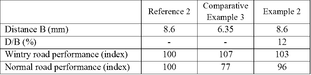
As seen from tables 1 and 2, the Examples show improvement on wintry (or white) road performance while maintaining on normal (or black) road performance.
The invention is not limited to the examples described and represented and various modifications can be made there without leaving its framework.
1, 21, 31 tread
2, 22, 32 contact face
3 main groove
4, 24, 34 cut(s)
41, 241, 341 cut(s)
5, 25, 35 contact element(s)
51, 251, 351 lateral wall(s)
52, 252, 352 edge portion
6, 26, 36 concavity
61, 261, 361 upper concavity edge portion
62, 262, 362 lower concavity edge portion
63, 263, 363 innermost portion
2, 22, 32 contact face
3 main groove
4, 24, 34 cut(s)
41, 241, 341 cut(s)
5, 25, 35 contact element(s)
51, 251, 351 lateral wall(s)
52, 252, 352 edge portion
6, 26, 36 concavity
61, 261, 361 upper concavity edge portion
62, 262, 362 lower concavity edge portion
63, 263, 363 innermost portion
Claims (7)
- A tread (1) for a tire having a contact face (2) intended to come into contact with ground during rolling, the tread (1) being provided with at least one main groove (3), a plurality of cuts (4, 41) opening to the contact face (2) extending as to crossing with the main groove (3) and substantially parallel one another, the plurality of cuts (4, 41) and the main groove (3) delimiting a plurality of contact elements (5), each the plurality of contact elements (5) having a plurality of lateral walls (51) facing to a cut (4, 41) among the plurality of cuts (4, 41) and/or the main groove (3), each the plurality of lateral walls (51) creating an edge portion (52) at an intersection with the contact face (2),
at least one of a lateral wall (51) among the plurality of lateral walls (51) forming a contact element (5) among the plurality of contact elements (5) being provided with a concavity (6) opening to the cut (4, 41) and/or to the main groove (3), the concavity (6) extending on the lateral wall (51) of the contact element (5) in a direction the cut (4, 41) or the main groove (3) is extending and over an entire width of the lateral wall (51) at a radial position where the concavity (6) being provided, on a plane perpendicular to both the contact face (2) and the lateral wall (51) provided with the concavity (6), the concavity (6) having two concavity edge portions at an intersection with the lateral wall (51), an upper concavity edge portion (61) being located radially outward and a lower concavity edge portion (62) being located radially inward, the lower concavity edge portion (62) being radially distant from radially innermost of the lateral wall (51) provided with the concavity (6) with a distance G,
the concavity (6) creating an innermost portion (63) the farthest from the lateral wall (51) in transverse direction on the plane, the cut (4, 41) having a depth H, two edge portions (52) being distant in transverse direction on the plane with a distance B, the innermost portion (63) of the concavity (6) being transversely inward of the contact element (5) from the closest edge portion (52) with a distance D,
the tread being characterized in that at a new state, a volume of the concavity (6) is at most equal to 5% of total volume of the contact element (5), and in that the distance D is in a range between 10% and 30% of the distance B, and in that a length of a virtual straight line connecting the lower concavity edge portion (62) and the innermost portion (63) is shorter than a length of a virtual straight line connecting the upper concavity edge portion (61) and the innermost portion (63). - The tread (1) according to claim 1, wherein the upper concavity edge portion (61) locates at a position more than 50% of the depth H radially inward from the contact face (2).
- The tread (1) according to claim 1 or claim 2, wherein the innermost portion (63) locates at a position radially equal to or inward of the lower concavity edge portion (62).
- The tread (1) according to any one of the claims 1 to 3, wherein a ratio between a radial distance between the upper concavity edge portion (61) and the lower concavity edge portion (62) is in a range between 50% and 180% of the distance D.
- The tread (1) according to any one of the claims 1 to 4, wherein the distance G is at least equal to 0.1mm.
- The tread (1) according to any one of the claims 1 to 5, wherein the two lateral walls (51) constituting the same contact element (5) are provided with the concavity (6).
- A tire having a tread according to any one of the claims 1 to 6.
Applications Claiming Priority (2)
| Application Number | Priority Date | Filing Date | Title |
|---|---|---|---|
| JP2017013526 | 2017-03-31 | ||
| JPPCT/JP2017/013526 | 2017-03-31 |
Publications (1)
| Publication Number | Publication Date |
|---|---|
| WO2018182041A1 true WO2018182041A1 (en) | 2018-10-04 |
Family
ID=62002343
Family Applications (1)
| Application Number | Title | Priority Date | Filing Date |
|---|---|---|---|
| PCT/JP2018/014038 Ceased WO2018182041A1 (en) | 2017-03-31 | 2018-04-02 | A tread having a block with a notch for improving snow performance |
Country Status (1)
| Country | Link |
|---|---|
| WO (1) | WO2018182041A1 (en) |
Cited By (3)
| Publication number | Priority date | Publication date | Assignee | Title |
|---|---|---|---|---|
| WO2021130879A1 (en) * | 2019-12-25 | 2021-07-01 | Compagnie Generale Des Etablissements Michelin | A tread for balanced performance |
| CN114599530A (en) * | 2019-11-06 | 2022-06-07 | 米其林集团总公司 | tires including tread |
| US12508844B2 (en) | 2019-11-06 | 2025-12-30 | Compagnie Generale Des Etablissements Michelin | Tire comprising a tread |
Citations (7)
| Publication number | Priority date | Publication date | Assignee | Title |
|---|---|---|---|---|
| EP0540340A2 (en) * | 1991-11-01 | 1993-05-05 | Bridgestone Corporation | Pneumatic tire, mold for manufacturing pneumatic tire, and method of manufacturing pneumatic tire using the mold |
| JPH11180115A (en) * | 1997-12-19 | 1999-07-06 | Bridgestone Corp | Pneumatic tire |
| DE102010017010A1 (en) * | 2010-05-18 | 2011-11-24 | Continental Reifen Deutschland Gmbh | Tread profile for vehicle pneumatic tire, has profile block row, which is limited in both axial directions by circumferential grooves, where radial external surface is formed in cross sectional planes |
| JP2012106707A (en) | 2010-10-22 | 2012-06-07 | Yokohama Rubber Co Ltd:The | Pneumatic tire |
| WO2014102039A1 (en) | 2012-12-28 | 2014-07-03 | Compagnie Generale Des Etablissements Michelin | Tread comprising sculpted elements comprising a covering layer |
| WO2015128106A1 (en) | 2014-02-27 | 2015-09-03 | Continental Reifen Deutschland Gmbh | Vehicle tires |
| WO2016158460A1 (en) * | 2015-03-31 | 2016-10-06 | コンパニー ゼネラール デ エタブリッスマン ミシュラン | Tire mold molding element, tire vulcanization molding mold, and tire |
-
2018
- 2018-04-02 WO PCT/JP2018/014038 patent/WO2018182041A1/en not_active Ceased
Patent Citations (7)
| Publication number | Priority date | Publication date | Assignee | Title |
|---|---|---|---|---|
| EP0540340A2 (en) * | 1991-11-01 | 1993-05-05 | Bridgestone Corporation | Pneumatic tire, mold for manufacturing pneumatic tire, and method of manufacturing pneumatic tire using the mold |
| JPH11180115A (en) * | 1997-12-19 | 1999-07-06 | Bridgestone Corp | Pneumatic tire |
| DE102010017010A1 (en) * | 2010-05-18 | 2011-11-24 | Continental Reifen Deutschland Gmbh | Tread profile for vehicle pneumatic tire, has profile block row, which is limited in both axial directions by circumferential grooves, where radial external surface is formed in cross sectional planes |
| JP2012106707A (en) | 2010-10-22 | 2012-06-07 | Yokohama Rubber Co Ltd:The | Pneumatic tire |
| WO2014102039A1 (en) | 2012-12-28 | 2014-07-03 | Compagnie Generale Des Etablissements Michelin | Tread comprising sculpted elements comprising a covering layer |
| WO2015128106A1 (en) | 2014-02-27 | 2015-09-03 | Continental Reifen Deutschland Gmbh | Vehicle tires |
| WO2016158460A1 (en) * | 2015-03-31 | 2016-10-06 | コンパニー ゼネラール デ エタブリッスマン ミシュラン | Tire mold molding element, tire vulcanization molding mold, and tire |
Non-Patent Citations (1)
| Title |
|---|
| SAM ELLA; PIERRE-YVES FORMAGNE; VASILEIOS KOUTSOS; JANE R. BLACKFORD: "Investigation of rubber friction on snow for tires", 38TH LEEDS-LYONS SYMPOSIUM ON TRIBOLOGY, LYONS, 6 September 2011 (2011-09-06) |
Cited By (5)
| Publication number | Priority date | Publication date | Assignee | Title |
|---|---|---|---|---|
| CN114599530A (en) * | 2019-11-06 | 2022-06-07 | 米其林集团总公司 | tires including tread |
| US20220410629A1 (en) * | 2019-11-06 | 2022-12-29 | Compagnie Generale Des Etablissements Michelin | Tire comprising a tread |
| CN114599530B (en) * | 2019-11-06 | 2023-10-20 | 米其林集团总公司 | Tires including tread |
| US12508844B2 (en) | 2019-11-06 | 2025-12-30 | Compagnie Generale Des Etablissements Michelin | Tire comprising a tread |
| WO2021130879A1 (en) * | 2019-12-25 | 2021-07-01 | Compagnie Generale Des Etablissements Michelin | A tread for balanced performance |
Similar Documents
| Publication | Publication Date | Title |
|---|---|---|
| JP4547012B2 (en) | Pneumatic tire | |
| US8307867B2 (en) | Pneumatic tire with tread including sipe having wide portions located alternately on both side walls | |
| JP6069709B2 (en) | Pneumatic tire tread | |
| JPH11129709A (en) | Pneumatic tire | |
| WO2018182041A1 (en) | A tread having a block with a notch for improving snow performance | |
| CN112585017B (en) | Pneumatic tire | |
| US11577552B2 (en) | Tire tread with sipes | |
| WO2019239570A1 (en) | A tread for winter and endurance | |
| AU2017402111B2 (en) | Pneumatic tire | |
| EP3814151B1 (en) | A tread for improved snow performance | |
| WO2020090884A1 (en) | A tire tread for improved snow performance | |
| WO2020129906A1 (en) | A tread for improved winter performance | |
| WO2019004414A1 (en) | A tread for improving snow performance | |
| EP4065388B1 (en) | A tread for improving wintry performance | |
| EP4065389B1 (en) | A tread for improving snow performance | |
| WO2021130879A1 (en) | A tread for balanced performance | |
| WO2020130115A1 (en) | A tread with incision for balanced performance | |
| CA3105061C (en) | A tread for improved snow performance | |
| JP7676550B2 (en) | Tire tread | |
| WO2022137316A1 (en) | A tire tread for long lasting performance | |
| EP3521062B1 (en) | Tire tread and tire having this tread | |
| US20110186199A1 (en) | Pneumatic Tire | |
| JP2005067232A (en) | Pneumatic tire |
Legal Events
| Date | Code | Title | Description |
|---|---|---|---|
| 121 | Ep: the epo has been informed by wipo that ep was designated in this application |
Ref document number: 18718237 Country of ref document: EP Kind code of ref document: A1 |
|
| NENP | Non-entry into the national phase |
Ref country code: DE |
|
| 122 | Ep: pct application non-entry in european phase |
Ref document number: 18718237 Country of ref document: EP Kind code of ref document: A1 |
|
| NENP | Non-entry into the national phase |
Ref country code: JP |