WO2018181675A1 - 植物栽培装置 - Google Patents
植物栽培装置 Download PDFInfo
- Publication number
- WO2018181675A1 WO2018181675A1 PCT/JP2018/013140 JP2018013140W WO2018181675A1 WO 2018181675 A1 WO2018181675 A1 WO 2018181675A1 JP 2018013140 W JP2018013140 W JP 2018013140W WO 2018181675 A1 WO2018181675 A1 WO 2018181675A1
- Authority
- WO
- WIPO (PCT)
- Prior art keywords
- nutrient solution
- solution storage
- plant cultivation
- unit
- cultivation apparatus
- Prior art date
- Legal status (The legal status is an assumption and is not a legal conclusion. Google has not performed a legal analysis and makes no representation as to the accuracy of the status listed.)
- Ceased
Links
Images

Classifications
-
- A—HUMAN NECESSITIES
- A01—AGRICULTURE; FORESTRY; ANIMAL HUSBANDRY; HUNTING; TRAPPING; FISHING
- A01G—HORTICULTURE; CULTIVATION OF VEGETABLES, FLOWERS, RICE, FRUIT, VINES, HOPS OR SEAWEED; FORESTRY; WATERING
- A01G31/00—Soilless cultivation, e.g. hydroponics
Definitions
- the present invention relates to a plant cultivation apparatus for cultivating plants such as vegetables.
- Patent Document 1 discloses a plant cultivation apparatus of this type.
- the plant cultivation device is a plurality of cocoons extending in one direction, each of which is a plurality of cocoons arranged in parallel to each other, and a plurality of cultivation trays placed on the plurality of cocoons, each of which is a plurality A plurality of the cultivation trays traversing the top of the basket, illumination for irradiating light to the plants planted in the plurality of cultivation trays, and a nozzle for supplying nutrient solution to the plurality of cultivation trays.
- Each ridge is inclined so that one end is slightly higher than the other end in the longitudinal direction of the ridge.
- Each cage has a placement area located at the center in the longitudinal direction, and an upper end area and a lower end area located at both ends in the longitudinal direction across the placement area. While the cultivation tray is placed in the placement area, the cultivation tray is not placed in the upper end area and the lower end area.
- a discharge port for discharging excess nutrient solution is provided at the bottom of the mounting area of each basket.
- Each cultivation tray is placed on a plurality of the aforementioned soot so that the roots of the plants planted in each cultivation tray are immersed in the nutrient solution.
- the inclination board which regulates storage of a nutrient solution is provided in the lower end area
- the inclined plate is inclined upward as it proceeds from the outlet to the downstream side of the soot so that the nutrient solution that flows through the outlet and flows to the lower end region flows back to the outlet.
- the present invention has been made paying attention to such problems existing in the prior art.
- the purpose is to provide a plant cultivation apparatus capable of suppressing the nutrient solution from being irradiated with light.
- the plant cultivation apparatus which solves the said subject is provided with the nutrient solution storage part in which the fixed planting plate by which the plant was planted is mounted.
- the said nutrient solution storage part has a non-mounting area
- the plant cultivation apparatus includes a light source that irradiates light to the plant.
- the plant cultivation apparatus includes a light shielding cover member. The cover member is configured to move between a closed position that covers the non-mounting area of the nutrient solution storage unit and an open position that opens the non-mounting area.
- the cover member by moving the cover member to the closed position, the light irradiated from the light source to the non-mounting area of the nutrient solution storage unit can be shielded by the cover member. Therefore, it can suppress that light is irradiated to the nutrient solution of the non-mounting area
- the plant cultivation device is capable of moving a plurality of the nutrient solution storage units, a plurality of cover members that can respectively cover the non-mounting regions of the plurality of nutrient solution storage units, and a plurality of the cover members. It is preferable to provide a moving mechanism.
- the plurality of cover members can be efficiently moved by simultaneously moving the plurality of cover members by the moving mechanism.
- the said plant cultivation apparatus WHEREIN It is preferable that the said cover member opens and closes the said non-mounting area
- a nutrient solution can be flowed over the other end part from the one end part in a nutrient solution storage part. For this reason, a nutrient solution can be spread throughout the nutrient solution reservoir.
- the size of the discharge port is larger than the size of the supply port.
- the plant cultivation device preferably further includes a moving mechanism that drives the cover member.
- the driving of the cover member can be automated and the working efficiency can be increased.
- the plant cultivation device further includes a plurality of the nutrient solution storage units and the cover member provided for each of the plurality of nutrient solution storage units, and the moving mechanism includes each of the cover members. It is preferably configured to move simultaneously.
- the plurality of cover members can be moved simultaneously by the moving mechanism. Therefore, the operation of the plurality of cover members becomes efficient.
- a large installation space can be secured in a relatively small installation location.
- the moving mechanism can be realized with a simple mechanism. Therefore, the operation of the cover member can be easily and inexpensively automated.
- the moving mechanism is fixed to at least one wire fixed to each of the plurality of cover members, and a first end portion of the wire, and a plurality of the cover members are respectively closed.
- a weight that applies a force to pull the wire vertically downward until it moves to a position, and a second end of the wire, and the plurality of cover members move to their open positions against the force of the weight
- an actuator configured to apply a force that pulls the wire vertically upward.
- the weight has a function of urging the cover member toward the non-mounting area of the nutrient solution reservoir. This urging force can act by the weight of the weight without requiring a special driving force. Therefore, the sealing performance of the cover member can be improved with an inexpensive configuration, and the light shielding effect can be enhanced.
- the said plant cultivation apparatus WHEREIN It is preferable that the said nutrient solution storage part contains the said several unit nutrient solution storage part of the same specification. According to this aspect, a large-scale nutrient solution reservoir can be configured by the unit nutrient solution reservoir of the same specification. Moreover, since the unit nutrient solution storage part has the same specification, mass production is easy and inexpensive.
- the said plant cultivation apparatus WHEREIN It is preferable that the several said unit nutrient solution storage part which comprises the said nutrient solution storage part is juxtaposed in the horizontal direction orthogonal to the said one direction. According to this aspect, it is possible to configure a non-mounting region in which openings of a plurality of unit nutrient solution storage units are arranged on one plane. Therefore, the apparatus can be embodied with a cover member having a simple specification.
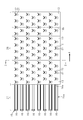
- FIG. 3 is an enlarged sectional view taken along line 3-3 in FIG.
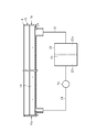
- the fluid circuit diagram which shows the connection state of a unit nutrient solution storage part, a nutrient solution tank, and a pump.
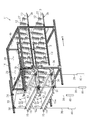
- the perspective view which shows a state when the cover member exists in the obstruction
- the plant cultivation apparatus 11 includes a growing rack 14.
- a plurality of fixed planting plates 13 are stored in the growing rack 14.
- the fixed planting board 13 is a synthetic resin product formed in a rectangular shape.
- plants 12 such as vegetables are planted on the planting board 13.
- the plant cultivation device 11 grows the plant 12 on the fixed planting plate 13 stored in the growing rack 14.
- a plurality (two in this embodiment) of nutrient solution reservoirs 15 are arranged inside the growth rack 14.
- each nutrient solution storage unit 15 a plurality of planting plates 13 on which plants 12 are planted are placed. These two nutrient solution storage parts 15 are opposed to each other in the vertical direction at a predetermined interval.
- Each nutrient solution storage unit 15 extends linearly along one direction A so as to penetrate the growth rack 14.
- Each nutrient solution storage unit 15 has a first end 15a and a second end 15b. The first end 15 a protrudes outward from the growth rack 14 from the inlet 14 a on the upstream side in the one direction A. The second end portion 15b protrudes from the outlet 14b to the outside of the growing rack 14 on the downstream side in the one direction A.
- the nutrient solution storage unit 15 includes a plurality (eight in this embodiment) of unit nutrient solution storage units 16.
- the unit nutrient solution reservoirs 16 have the same specifications (same dimensions and shapes). In some embodiments, a plurality of unit nutrient reservoirs with different specifications may be combined.
- the unit nutrient solution storage part 16 is formed in a bowl shape extending in the longitudinal direction, and has a bottomed rectangular box shape with an open upper end. Each unit nutrient solution storage part 16 extends in parallel with each other along one direction A. In the illustrated example, the unit nutrient solution storage portions 16 are arranged at equal intervals at a predetermined pitch. However, the eight unit nutrient solution reservoirs 16 do not necessarily have to be arranged at equal intervals in the width direction.
- each unit nutrient solution storage unit 16 includes a supply port 19 provided on the bottom wall of the first end portion 15 a (upstream side in one direction A) of the unit nutrient solution storage unit 16.
- the supply port 19 is an opening for supplying the nutrient solution 18 into the unit nutrient solution storage unit 16.
- Each unit nutrient solution storage unit 16 includes a discharge port 20 provided on the bottom wall of the second end portion 15b (downstream side in one direction A) of the unit nutrient solution storage unit 16.
- the discharge port 20 is an opening for discharging the nutrient solution 18 in the unit nutrient solution storage unit 16.
- the inner diameter of the discharge port 20 is larger than the inner diameter of the supply port 19.
- the plant cultivation device includes a nutrient solution tank 22.
- the nutrient solution 18 is stored in the nutrient solution tank 22.
- the nutrient solution tank 22 includes a filter 23 therein.
- the filter 23 partitions the inside of the nutrient solution tank 22 into an upstream chamber 22a and a downstream chamber 22b, and filters the nutrient solution 18 from the upstream chamber 22a to the downstream chamber 22b.
- the discharge port 20 is connected to the upstream chamber 22 a of the nutrient solution tank 22 via the discharge channel 21.
- the supply port 19 is connected to the downstream chamber 22 b via the supply flow path 24.
- a supply pump 25 that feeds the nutrient solution 18 from the nutrient solution tank 22 toward the supply port 19 is provided in the supply channel 24.
- the supply pump 25 supplies the nutrient solution 18 from the nutrient solution tank 22 into the unit nutrient solution reservoir 16 through the supply port 19.
- the supplied nutrient solution 18 flows in the unit nutrient solution reservoir 16 from the first end 15a toward the second end 15b, and is discharged from the discharge port 20.
- the nutrient solution 18 discharged from the discharge port 20 enters the upstream chamber 22 a of the nutrient solution tank 22 and is filtered by the filter 23. Waste in the nutrient solution 18 is removed by the filter 23.
- the filtered nutrient solution 18 is supplied again from the downstream chamber 22 b into the unit nutrient solution storage unit 16 via the supply path 24 and the supply port 19. That is, the nutrient solution 18 is circulated.
- a plurality of light sources 26 for irradiating the plant 12 with light are disposed above each nutrient solution storage unit 15 in the growth rack 14.
- the light source 26 may use a light emitting diode (LED), for example.
- the light from the light source 26 is suitable for growing the plant 12.
- the light from the light source 26 illuminates the leaves 27 of the plant 12 planted on the planting board 13.
- algae and bacteria may be generated.
- the plurality of planting boards 13 juxtaposed on the upper part of the nutrient solution nutrient solution storage unit 15 are in contact with each other in one direction A and are adjacent to each other. There is almost no gap between them. Therefore, the inside of the nutrient solution storage part 15 (unit nutrient solution storage part 16) through which the nutrient solution 18 flows is substantially shielded from light by the plurality of fixed planting plates 13. Therefore, almost no algae or bacteria are generated inside the nutrient solution reservoir 15 (unit nutrient solution reservoir 16). That is, in the area shielded by the fixed planting plate 13, no light is applied to the nutrient solution storage part 15, so that algae and bacteria are hardly generated.
- the plurality of planting boards 13 on which the plants 12 are planted on the nutrient solution storage unit 15 are sequentially conveyed from the outlet 14b to the shipping place.
- the downstream end wall of the fixed planting plate 13 located on the most downstream side in the one direction A is substantially flush with the downstream end wall of the nutrient solution storage unit 15.
- the plurality of fixed planting plates 13 on the nutrient solution storage unit 15 are sequentially transferred from the inlet 14 a to the outlet 14 b of the growth rack 14. Specifically, the planting plate 13 in which the plant 12 before growth is planted is first placed on the first end portion 15a on the nutrient solution storage unit 15. A width of the fixed planting plate 13 is arranged along one direction A. Next, after the period necessary for the growth of the plant has elapsed, the placed fixed planting plate 13 is pushed in one direction A by the width of the fixed planting plate 13. The plurality of planting plates 13 are sequentially slid in one direction A on the nutrient solution storage unit 15. In this manner, the plant cultivation device 11 enables continuous shipment of the plants 12.
- the growing period of the plant 12 is set longer as the fixed planting plate 13 is closer to the second end portion 15b of the nutrient solution storage unit 15. Therefore, the plant grows larger as it is planted on the planting board 13 near the second end 15b.
- the nutrient solution storage unit 15 includes a placement area 28 and a non-placement area 29.
- the placement area 28 includes a plurality of planting plates 13 to be placed on the nutrient solution storage unit 15 and a plurality of planting plates 13 that are placed on the nutrient solution storage unit 15 are not transported to the shipping location. This is the position where the fixed planting board 13 is permanently installed.
- the placement area 28 is a portion other than the first end 15 a on the nutrient solution storage unit 15.
- the non-mounting area 29 is the first end 15 a on the nutrient solution storage section 15. When the predetermined number of planting plates 13 are not added to the nutrient solution storage unit 15 or when the planting plate 13 on the nutrient solution storage unit 15 is not transported to the shipping place, the planting plate 13 is not placed in the non-mounting area 29. Not placed.
- a pair of arms 30 is provided at the inlet 14 a of the growth rack 14 for each nutrient solution storage unit 15.
- the pair of arms 30 are disposed at both ends in the width direction of the inlet 14a so as to sandwich the both sides in the width direction of the first end 15a of the corresponding nutrient solution storage section 15, and the length of the growth rack 14 from the inlet 14a. Extends outward in the direction.
- the pair of arms 30 are connected by a pair of connecting rods 31 extending in the width direction of the growing rack 14.
- the pair of connecting rods 31 extend so as to pass below the first end portion 15 a of the nutrient solution storage unit 15.
- strip-shaped planting plate guides 32 are erected.
- the guide 32 is for guiding the fixed planting plate 13 when the fixed planting plate 13 is placed on the first end 15 a of the nutrient solution storage unit 15.
- the growing rack 14 includes a pair of frames 33 provided at both ends in the width direction on the upper surface of the growing rack 14.
- the pair of frames 33 extend from the inlet 14 a toward the outside in the longitudinal direction so as to be positioned directly above the pair of arms 30.
- the growing rack 14 includes first pulleys 34 that are provided on each of the pair of frames 33. Each first pulley 34 faces the width direction of the growing rack 14 at a predetermined interval in one direction A.
- the pair of frames 33 may include three or more first pulleys 34.
- the growing rack 14 includes four second pulleys 35 provided on one frame 33 of the pair of frames 33 in the vicinity of the inlet 14 a of the growing rack 14.
- the growing rack 14 includes an air cylinder 36 provided on the side of the growing rack 14 on the inlet 14a side.
- the air cylinder 36 is an example of an actuator and extends in the vertical direction.
- the air cylinder 36 is fixed in the vicinity of the second pulley 35 in the width direction of the growing rack 14.
- the air cylinder 36 has a rod 37.
- the rod 37 is driven by the air cylinder 36 so that the ascending position (position shown in FIG. 5) advances from the air cylinder 36 vertically upward, and the descending position (FIG. 1) where the rod 37 enters the air cylinder 36 downward vertically.
- An L-shaped attachment member 38 is fixed to the tip of the rod 37.
- the plant cultivation device 11 includes a light-shielding cover member 41 for each nutrient solution storage unit 15.
- Each cover member 41 faces the first end portion 15a of the corresponding nutrient solution storage portion 15 from above, and faces the non-mounting area 29 to the openable / closable cover member.
- the cover member 41 can be made of any material having a light shielding property, such as synthetic resin, metal, wood, ceramic, paper, and the like. In the present embodiment, the cover member 41 is made of black plastic cardboard.
- each cover member 41 includes a rectangular plate-shaped cover member main body 42 and a pair of strip-shaped ribs 43 provided on the upper surface of the cover member main body 42.
- the pair of ribs 43 are arranged at a predetermined interval in the longitudinal direction of the nutrient solution reservoir 15, and extend parallel to each other along the width direction of the nutrient solution reservoir 15. Both ends of the pair of ribs 43 protrude outward in the width direction from the cover member main body 42.
- the rib 43 is formed by bonding two long plates 44 together.
- Each arm 30 includes a wire guide 45 provided at a position corresponding to the wire 39 of each arm.
- the wire guide 45 is formed in a U shape so as to guide the wire 39 in the vertical direction.
- the wire guide 45 may be formed integrally with the arm 30 or may be formed separately from the arm 30.
- each wire 39 is pulled vertically downward by the weight of the weight 40. For this reason, the part from the 1st pulley 34 to the weight 40 in each wire 39 falls together with each cover member 41. Thereby, each cover member 41 is simultaneously moved to the closed position (position shown in FIG. 5) covering the non-mounting area 29. In the closed position, the weight of each weight 40 acts on the cover member 41. This force acts as a biasing force that biases the cover member 41 to the upper surfaces of the plurality of unit nutrient solution storage units 16.
- each wire 39 is pulled by the mounting member 38. For this reason, the part from the 1st pulley 34 to the weight 40 in each wire 39 goes up with each cover member 41 together. Thereby, each cover member 41 is moved to the open position (position shown in FIG. 1) that opens the non-mounting area 29.
- each cover member 41 is simultaneously moved between a closed position for closing the non-mounting area 29 and an open position for opening the non-mounting area 29 by driving the air cylinder 36. That is, the two cover members 41 simultaneously open and close the non-mounting areas 29 of the two nutrient solution storage portions 15 by moving in the vertical direction as the four wires 39 are moved by driving one air cylinder 36. To do.
- a plurality of (two in this embodiment) cover members 41 can be moved simultaneously by the air cylinder 36, the mounting member 38, the wire 39, the first pulley 34, the second pulley 35, and the weight 40.
- a simple moving mechanism A simple moving mechanism.
- action of the plant cultivation apparatus 11 is demonstrated.
- the plurality of planting plates 13 are The cover member 41 is placed on the non-placement region 29 while being placed on the placement region 28.
- the planting plate 13 is transported to a shipping place by a transport device (not shown). The Thereby, in the 2nd end part 15b of each nutrient solution storage part 15, the space for one fixed planting board 13 conveyed to the shipping place is made.
- each wire 39 is pulled by the rod 37 via the attachment member 38. Then, the portion from the first pulley 34 to the weight 40 in each wire 39 rises together with the cover member 41 and the cover member cover member 41 is simultaneously moved from the closed position to the open position. Thereby, each cover member 41 of a cover member raises to a position slightly higher than the fixed planting plate guide 32, and the non-mounting area
- the planting plate 13 on which the plant 12 before growth is planted is placed in the open non-mounting area 29 on each nutrient solution storage unit 15.
- region 29 is obstruct
- the fixed planting plate 13 placed in the non-mounting region 29 is pushed in one direction A by the pressing device (not shown) by the longitudinal width of the nutrient solution storage unit 15 in the fixed planting plate 13.
- all the fixed planting plates 13 on each nutrient solution storage unit 15 are slid in one direction A by the longitudinal width of the nutrient solution storage unit 15 in the planting plate 13.
- each nutrient solution storage part 15 when adding the fixed planting board 13 on the nutrient solution storage part 15, or conveying the fixed planting board 13 on the nutrient solution storage part 15 to a shipping place, each nutrient solution storage part 15 temporarily.
- the upper non-mounting area 29 is opened.
- the time during which the light from the light source 26 strikes the nutrient solution 18 flowing through the non-placement area 29 is long. Very short. For this reason, generation
- the plant cultivation apparatus 11 includes a light-shielding cover member 41 that is movable between a closed position that covers the non-placement area 29 of the nutrient solution storage unit 15 and an open position that opens the non-placement area 29. .
- the cover member 41 can block the light irradiated from the light source 26 to the non-mounting area 29 of the nutrient solution storage unit 15 by moving the cover member 41 to the closed position. Therefore, it can suppress effectively that light is irradiated to the nutrient solution 18 from the non-mounting area
- the plant cultivation apparatus 11 includes a moving mechanism that can move a plurality (two in this example) of the cover members 41. For this reason, the plurality of cover members 41 can be efficiently moved by simultaneously moving the plurality of cover members 41 by the moving mechanism. That is, in the plant cultivation apparatus 11, all the cover members 41 can be moved simultaneously between the closed position and the open position by driving one air cylinder 36, so that the plurality of cover members 41 can be moved efficiently. Can be made.
- the cover member 41 opens and closes the non-mounting area 29 by moving in the vertical direction. For this reason, since it is not necessary to ensure the space for moving the cover member 41 to a horizontal direction, the installation area of the plant cultivation apparatus 11 can be reduced.
- the supply port 19 to which the nutrient solution 18 is supplied is provided at the first end portion 15a of the unit nutrient solution storage unit 16 (the nutrient solution storage unit 15).
- a discharge port 20 through which the nutrient solution 18 is discharged is provided at the second end portion 15b of the (nutrient solution storage unit 15).
- the whole of the unit nutrient solution storage unit 16 (the nutrient solution storage unit 15) can be washed away with the nutrient solution 18, garbage and shredded plants in the unit nutrient solution storage unit 16 (the nutrient solution storage unit 15). Accumulation of 12 roots 17 and the like can be suppressed.
- the size of the discharge port 20 is larger than the size of the supply port 19. For this reason, the waste mixed in the nutrient solution 18 and the roots 17 of the shredded plant 12 can be smoothly discharged from the discharge port 20.
- the air cylinder 36 is disposed at the lower part of the growing rack 14. For this reason, since the air cylinder 36 can be accessed without climbing the growth rack 14, the movement amount and movement speed of the cover member 41 can be easily adjusted.
- the plant cultivation device 11 further includes a moving mechanism (the air cylinder 36, the attachment member 38, the wire 39, the first pulley 34, the second pulley 35, and the weight 40) that drives the cover member 41. For this reason, the drive of the cover member 41 can be automated and work efficiency can be improved.
- a moving mechanism the air cylinder 36, the attachment member 38, the wire 39, the first pulley 34, the second pulley 35, and the weight 40
- the plant cultivation apparatus 11 further includes a plurality (two in this example) of nutrient solution storage units 15 and a cover member 41 provided for each of the plurality of nutrient solution storage units 15, and a moving mechanism.
- the air cylinder 36, the mounting member 38, the wire 39, the first pulley 34, the second pulley 35, and the weight 40 are configured to move each of the cover members 41 simultaneously. For this reason, since the plurality of cover members 41 can be simultaneously moved by the moving mechanism (the air cylinder 36, the mounting member 38, the wire 39, the first pulley 34, the second pulley 35, and the weight 40), the plurality of cover members The operation of 41 becomes efficient.
- the plurality of nutrient solution storage parts 15 are arranged at intervals in the vertical direction. For this reason, a large-area mounting space can be secured in a relatively small installation area of the cover member.
- the moving mechanism can be realized with a simple mechanism. Therefore, the operation of the cover member can be easily and inexpensively automated.
- the moving mechanism of the plant cultivation device 11 is fixed to at least one wire 39 fixed to each of the plurality of cover members 41, and the first end (tip portion) of the wire 39, and includes a plurality of A weight 40 that applies a force to pull the wire 39 vertically downward until the cover member 41 moves to each closed position, and a second end (base end) of the wire 39, and the force of the weight 40 And an air cylinder 36 configured to apply a force to pull the wire 39 vertically upward until the plurality of cover members 41 move to their open positions.
- the moving mechanism which drives the cover member 41 all at once with a simple mechanism can be embodied.
- the weight 40 has a function of urging the cover member 41 toward the non-mounting area 29 of the nutrient solution storage unit 15.
- This urging force can act by the weight of the weight 40 without requiring a special driving force. Therefore, the sealing performance of the cover member 41 can be improved with a low-cost configuration, and the light shielding effect can be enhanced.
- the nutrient solution storage unit 15 of the plant cultivation apparatus 11 is at least one unit nutrient solution storage unit 16 and at least one unit nutrient solution storage unit formed in a bowl shape extending along one direction.
- at least one unit nutrient solution storage unit 16 is provided at the first end 15 a in the longitudinal direction of the unit nutrient solution storage unit 16, a supply port 19 through which the nutrient solution is supplied, and the unit nutrient solution It is provided in the 2nd end part 15b in the longitudinal direction of the liquid storage part 16, and is provided with the discharge port 20 through which nutrient solution is discharged. For this reason, a nutrient solution can be flowed from the one end part in the nutrient solution nutrient solution storage part 15 to the other end part.
- the nutrient solution can be spread throughout the nutrient solution nutrient solution storage unit 15. Moreover, the nutrient solution storage part 15 from which a specification differs can be comprised by selecting the number of the unit nutrient solution storage parts 16 of the same specification arbitrarily.
- the inner diameter of the discharge port 20 of the unit nutrient solution storage unit 16 of the plant cultivation device 11 is larger than the inner diameter of the supply port 19. For this reason, the waste mixed with the nutrient solution, the roots of broken plants, and the like can be discharged smoothly from the discharge port 20.
- the nutrient solution reservoir 15 of the plant cultivation apparatus 11 includes a plurality of unit nutrient solution reservoirs 16 having the same specifications. For this reason, the large-scale nutrient solution storage part 15 can be comprised by the unit nutrient solution storage part 16 of the cover member same specification. Moreover, since the unit nutrient solution storage part 16 is the same specification, mass production becomes easy and cheap.
- the plurality of unit nutrient solution storage units 16 constituting the nutrient solution storage unit 15 of the plant cultivation apparatus 11 are juxtaposed in a horizontal direction orthogonal to one direction. For this reason, the non-mounting area
- the size of the discharge port 20 is not necessarily larger than the size of the supply port 19. In some embodiments, the size of the outlet 20 may be less than or equal to the size of the supply port 19.
- the supply port 19 does not necessarily need to be provided in the 1st end part 15a of the unit nutrient solution storage part 16 (nutrient solution storage part 15), and the discharge port 20 does not necessarily have to be the unit nutrient solution storage part 16. It is not necessary to provide in the 2nd end part 15b of (the nutrient solution storage part 15). In some embodiments, the positions of the supply port 19 and the discharge port 20 in the unit nutrient solution storage unit 16 (the nutrient solution storage unit 15) may be changed as appropriate.
- the cover member 41 does not necessarily need to open and close the non-mounting area
- the cover member 41 may open and close the non-mounting region 29 by moving in the horizontal direction or rotating (including double doors).
- the moving mechanism may be omitted.
- the nutrient solution storage part 15 may be comprised by one water tank.
- the water tank is an example of the unit nutrient solution storage unit 16.
- the water tank may be formed in a box shape having an upper end opened.
- the nutrient solution nutrient storage part 15 may be one. Three or more nutrient solution storage units 15 may be provided. -In the plant cultivation apparatus 11, you may arrange
- the rib 43 may be omitted from the cover member 41.
- the cover member main body 42 of the cover member 41 may be fixed to each wire 39.
- the weight 40 may be abbreviate
- the actuator may be an electric cylinder, a hydraulic cylinder, an electric reel that can wind up each wire 39 or a manual reel instead of the air cylinder 36.
- the plant cultivation apparatus 11 provides the cover member 41 outside the exit 14b of the growth rack 14, and the nutrient solution storage part 15 after the fixed planting board 13 located in the 2nd end part 15b of the nutrient solution storage part 15 is conveyed.
- the space on the second end 15b may be covered by the cover member 41.
Landscapes
- Life Sciences & Earth Sciences (AREA)
- Environmental Sciences (AREA)
- Hydroponics (AREA)
Abstract
養液に光が照射されることを抑制できる植物栽培装置(11)を提供する。植物栽培装置(11)は、植物(12)が定植される定植板(13)が載置される養液貯留部(15)を備える。養液貯留部(15)は、定植板(13)の常設が除外される非載置領域(29)を有し、植物(12)の根が浸される養液を貯留する。装置(11)は、植物(12)に光を照射する光源(26)を備える。装置(11)は、遮光性のカバー部材(41)を備える。カバー部材(41)は、養液貯留部(15)の非載置領域(29)を覆う閉塞位置と非載置領域(29)を開放する開放位置との間で移動するように構成される。
Description
本発明は、例えば野菜などの植物を栽培する植物栽培装置に関する。
例えば特許文献1は、この種の植物栽培装置を開示している。前記植物栽培装置は、一方向に延びる複数の樋であって、それぞれが互いに平行に配置された複数の樋と、複数の前記樋上に載置される複数の栽培トレイであって、それぞれが複数の前記樋上を横切る複数の前記栽培トレイと、複数の前記栽培トレイに植栽された植物に光を照射する照明と、複数の前記栽培トレイに養液を供給するノズルとを備える。各樋は、当該樋の長手方向において一端が他端よりも僅かに高くなるように傾斜している。
各樋は、長手方向の中央部に位置する載置領域と、載置領域を挟む長手方向の両端部に位置する上端領域及び下端領域とを有する。載置領域には、栽培トレイが載置される一方、上端領域及び下端領域には、栽培トレイは載置されない。各樋の載置領域の底には、余剰の養液を排出するための排出口が設けられる。各栽培トレイは、各栽培トレイに植栽された植物の根が養液に浸されるように複数の前記樋の上に載置される。
上述のような植物栽培装置において、養液に光が照射されると、藻や細菌などが発生するため、養液に光が照射されないようにする必要がある。このため、各樋の下端領域には、養液の貯留を規制する傾斜板が設けられている。傾斜板は、排出口を通過して下端領域に流れようとする養液を排出口へ逆流させるように、排出口から当該樋の下流側に進むに連れて上方へ傾斜している。
しかし、特許文献1の植物栽培装置では、傾斜板上に養液の水滴や千切れた植物の根などが残ることがある。傾斜板上の養液の水滴や千切れた植物の根に光が照射される場合、藻や細菌などが発生するという問題があった。
本発明は、このような従来技術に存在する問題点に着目してなされた。その目的は、養液に光が照射されることを抑制できる植物栽培装置を提供することにある。
以下、前記課題を解決するための手段及びその作用効果について記載する。
前記課題を解決する植物栽培装置は、植物が定植された定植板が載置される養液貯留部を備える。前記養液貯留部は、前記定植板の常設が除外される非載置領域を有し、前記植物の根が浸される養液を貯留する。前記植物栽培装置は、前記植物に光を照射する光源を備える。前記植物栽培装置は、遮光性のカバー部材を備える。前記カバー部材は、前記養液貯留部の前記非載置領域を覆う閉塞位置と前記非載置領域を開放する開放位置との間で移動するように構成される。
前記課題を解決する植物栽培装置は、植物が定植された定植板が載置される養液貯留部を備える。前記養液貯留部は、前記定植板の常設が除外される非載置領域を有し、前記植物の根が浸される養液を貯留する。前記植物栽培装置は、前記植物に光を照射する光源を備える。前記植物栽培装置は、遮光性のカバー部材を備える。前記カバー部材は、前記養液貯留部の前記非載置領域を覆う閉塞位置と前記非載置領域を開放する開放位置との間で移動するように構成される。
この態様によれば、カバー部材を閉塞位置に移動させることで、光源から養液貯留部の非載置領域に照射される光をカバー部材によって遮光することができる。よって、養液貯留部における非載置領域の養液に光が照射されることを抑制できる。
前記植物栽培装置は、複数の前記養液貯留部と、複数の前記養液貯留部の前記非載置領域をそれぞれ覆うことが可能な複数の前記カバー部材と、複数の前記カバー部材を移動可能な移動機構と、を備えることが好ましい。
この構成によれば、複数のカバー部材を移動機構によって同時に移動させることで、複数のカバー部材を効率的に移動させることができる。
前記植物栽培装置において、前記カバー部材は、鉛直方向への移動により前記非載置領域を開閉することが好ましい。
前記植物栽培装置において、前記カバー部材は、鉛直方向への移動により前記非載置領域を開閉することが好ましい。
この構成によれば、カバー部材が鉛直方向への移動により非載置領域を開閉するため、水平方向にカバー部材を移動させるためのスペースを確保する必要がない。このため、植物栽培装置の設置面積を低減できる。
前記植物栽培装置において、前記養液貯留部は、一方向に延びており、前記養液貯留部の長手方向における一端部には前記養液が供給される供給口が設けられ、前記養液貯留部の長手方向における他端部には前記養液が排出される排出口が設けられていることが好ましい。
この構成によれば、養液貯留部内の一端部から他端部に亘って養液を流すことができる。このため、養液貯留部内の全体に養液を行き渡らせることができる。
前記植物栽培装置において、前記排出口の大きさは、前記供給口の大きさよりも大きいことが好ましい。
前記植物栽培装置において、前記排出口の大きさは、前記供給口の大きさよりも大きいことが好ましい。
この構成によれば、養液に混じったごみや千切れた植物の根などを排出口から円滑に排出することができる。
前記植物栽培装置において、前記カバー部材を駆動する移動機構をさらに備えることが好ましい。
前記植物栽培装置において、前記カバー部材を駆動する移動機構をさらに備えることが好ましい。
この態様によれば、カバー部材の駆動を自動化し、作業効率を高めることができる。
前記植物栽培装置は、複数の前記養液貯留部と、複数の前記養液貯留部ごとに1つずつ設けられた前記カバー部材と、をさらに備え、前記移動機構は、前記カバー部材のそれぞれを同時に移動するように構成されることが好ましい。
前記植物栽培装置は、複数の前記養液貯留部と、複数の前記養液貯留部ごとに1つずつ設けられた前記カバー部材と、をさらに備え、前記移動機構は、前記カバー部材のそれぞれを同時に移動するように構成されることが好ましい。
この態様によれば、複数のカバー部材を移動機構によって同時に移動させることができる。よって、複数のカバー部材の操作が効率的になる。
前記植物栽培装置において、複数の前記養液貯留部は、上下に間隔を隔てて配置されていることが好ましい。
前記植物栽培装置において、複数の前記養液貯留部は、上下に間隔を隔てて配置されていることが好ましい。
この態様によれば、比較的面積の狭い設置場所に大面積の載置スペースを確保できる。加えて、複数のカバー部材を同一平面上に配置することにより、簡易な機構で移動機構を具体化することができる。よって、カバー部材の操作が容易かつ低廉に自動化可能となる。
前記植物栽培装置において、前記移動機構は、複数の前記カバー部材のそれぞれと固定される少なくとも1本のワイヤーと、前記ワイヤーの第1端部に固定され、複数の前記カバー部材がそれぞれの前記閉塞位置に移動するまで当該ワイヤーを鉛直下方に引く力を付与する錘と、前記ワイヤーの第2端部に連結され、前記錘の力に抗して複数の前記カバー部材がそれぞれの開放位置に移動するまでワイヤーを鉛直上方に引く力を付与するように構成されたアクチュエータと、を備えることが好ましい。
この態様によれば、簡便な機構でカバー部材を一斉に駆動する移動機構を具体化することができる。また、錘は、カバー部材を養液貯留部の非載置領域に向かって付勢する機能を奏する。この付勢力は、特別な駆動力を要することなく、錘の自重で作用し得る。よって、低廉な構成でカバー部材のシール性が向上し、遮光効果を高め得る。
前記植物栽培装置において、前記養液貯留部は、少なくとも1本の単位養液貯留部であって、一方向に沿って延びる樋形状に形成された前記少なくとも1本の単位養液貯留部を含み、前記少なくとも一本の単位養液貯留部は、当該単位養液貯留部の長手方向における一端部に設けられ、かつ、前記養液が供給される供給口と、当該単位養液貯留部の長手方向における他端部に設けられ、かつ、前記養液が排出される排出口と、を備えることが好ましい。
この態様によれば、養液貯留部内の一端部から他端部に亘って養液を流すことができる。よって、養液貯留部内の全体に養液を行き渡らせることができる。また、同一仕様の単位養液貯留部の本数を任意に選択することにより、仕様の異なる養液貯留部を構成することができる。この場合においても、前記植物栽培装置において、前記排出口の大きさは、前記供給口の大きさよりも大きいことが好ましい。
前記植物栽培装置において、前記養液貯留部は、同一仕様の複数の前記単位養液貯留部を含むことが好ましい。
この態様によれば、同一仕様の単位養液貯留部により、大規模な養液貯留部を構成することができる。また、単位養液貯留部が同一仕様であることから、量産が容易かつ廉価になる。
この態様によれば、同一仕様の単位養液貯留部により、大規模な養液貯留部を構成することができる。また、単位養液貯留部が同一仕様であることから、量産が容易かつ廉価になる。
前記植物栽培装置において、前記養液貯留部を構成する複数の前記単位養液貯留部は、前記一方向と直交する水平方向に並置されることが好ましい。
この態様によれば、一平面上に複数の単位養液貯留部の開口が並ぶ非載置領域を構成できる。したがって、単純な仕様のカバー部材で装置を具体化することができる。
この態様によれば、一平面上に複数の単位養液貯留部の開口が並ぶ非載置領域を構成できる。したがって、単純な仕様のカバー部材で装置を具体化することができる。
本発明によれば、養液に光が照射されることを抑制できる。
以下、植物栽培装置の一実施形態を図面に従って説明する。
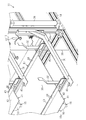
図1に示すように、植物栽培装置11は、育成ラック14を備えている。育成ラック14には、複数の定植板13が保管される。定植板13は、矩形に形成された合成樹脂製品である。定植板13には、例えば野菜などの植物12が定植される。植物栽培装置11は、育成ラック14に保管された前記定植板13上の植物12を育成する。
図1に示すように、植物栽培装置11は、育成ラック14を備えている。育成ラック14には、複数の定植板13が保管される。定植板13は、矩形に形成された合成樹脂製品である。定植板13には、例えば野菜などの植物12が定植される。植物栽培装置11は、育成ラック14に保管された前記定植板13上の植物12を育成する。
育成ラック14は、直方体形状の枠体である。育成ラック14は、当該育成ラック14の長手方向の一端部に形成された入口14aと、他端部に形成された出口14bとを有する。以下の説明では、矢印Aで示すように、入口14aから出口14bに向かう水平方向を「一方向A」という。
育成ラック14の内部には、複数(本実施形態では2つ)の養液リザーバ15が配置される。各養液貯留部15には、植物12が定植された複数の定植板13が載置される。これら2つの養液貯留部15は、鉛直方向に所定の間隔を置いて上下に対向している。各養液貯留部15は、育成ラック14を貫くように、一方向Aに沿って直線状に延びる。各養液貯留部15は、第1端部15a及び第2端部15bを有する。第1端部15aは、一方向Aの上流側において、入口14aから育成ラック14の外方に突出している。第2端部15bは、一方向Aの下流側において、出口14bから育成ラック14の外側に突出している。
養液貯留部15は、複数(本実施形態では8つ)の単位養液貯留部16によって構成されている。図示の実施形態において、各単位養液貯留部16は、同一仕様(同一寸法・同一形状)である。いくつかの実施形態において、複数の異なる仕様の単位養液貯留部を組み合わせてもよい。
単位養液貯留部16は、長手方向に延びる樋状に形成され、上端が開口した有底矩形箱状を有している。各単位養液貯留部16は、一方向Aに沿って互いに平行に延びる。図示の例において、各単位養液貯留部16は所定のピッチで等間隔に配置されている。ただし、8つの単位養液貯留部16は、必ずしも幅方向において等間隔となるように配置する必要はない。
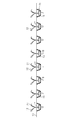
図2及び図3に示すように、養液リザーバ15上には、複数の定植板13が摺動可能に載置される。各定植板13は、養液貯留部15の長手方向に沿って並置される。各定植板13の上には、複数の植物12が幅方向においてジグザグ(いわゆる千鳥状)に並ぶように定植される。ただし、複数の植物12は、必ずしもジグザグ(いわゆる千鳥状)に配置する必要はない。定植板13は、養液貯留部15を構成する8つの単位養液貯留部16を横切って横架される。植物12の根17の先端部は、単位養液貯留部16内に貯留された養液18に浸されている。
図4に示すように、各単位養液貯留部16は、単位養液貯留部16の第1端部15a(一方向Aの上流側)における底壁に設けられた供給口19を備える。供給口19は、単位養液貯留部16内に養液18を供給するための開口である。各単位養液貯留部16は、単位養液貯留部16の第2端部15b(一方向Aの下流側)における底壁に設けられた排出口20を備える。排出口20は、単位養液貯留部16内の養液18を排出するための開口である。排出口20の内径は、供給口19の内径よりも大きい。
植物栽培装置は、養液タンク22を備える。養液タンク22には、養液18が貯留される。養液タンク22は、フィルター23を内部に備えている。フィルター23は、養液タンク22の内部を上流室22aと下流室22bとに仕切り、養液18を上流室22aから下流室22bに濾過する。排出口20は、排出流路21を介して養液タンク22の上流室22aに接続されている。供給口19は、供給流路24を介しての下流室22bに接続されている。供給流路24には、養液タンク22から供給口19に向かって養液18を送り出す供給ポンプ25が設けられている。
供給ポンプ25は、養液タンク22から供給口19を介して単位養液貯留部16内に養液18を供給する。供給された養液18は、単位養液貯留部16内を第1端部15aから第2端部15bに向かって流れ、排出口20から排出される。排出口20から排出された養液18は、養液タンク22の上流室22aに入り、フィルター23で濾過される。養液18中のごみなどは、フィルター23で除去される。濾過された養液18は、下流室22bから再び供給経路24及び供給口19を経由して単位養液貯留部16内に供給される。つまり、養液18は循環している。
図1に示すように、育成ラック14内における各養液貯留部15の上方には、植物12に光を照射する複数の光源26が配置されている。光源26は、例えば発光ダイオード(LED)を用いたものであってもよい。光源26からの光は、植物12を生長させるために好適である。光源26からの光は、定植板13に定植された植物12の葉27を照らす。一方、光が養液18に当たると、藻や細菌が発生する虞がある。
しかしながら、本実施形態において、養液養液貯留部15(単位養液貯留部16)の上部に並置されている複数の定植板13は、一方向Aにおいて、互いに接触し、隣接する定植板13の間には、ほとんど隙間がない。そのため、養液18が流れる養液貯留部15(単位養液貯留部16)内は、複数の定植板13によって、実質的に遮光されている。したがって、養液貯留部15(単位養液貯留部16)の内部において、藻や細菌は、ほとんど発生しない。すなわち、定植板13に遮蔽された領域においては、養液貯留部15内に光が当たらないため、藻や細菌がほとんど発生しない。
養液貯留部15上において植物12が定植された複数の定植板13は、出口14bから順に出荷場所へ搬送される。一方向Aの最下流に位置する定植板13の下流端壁は、養液貯留部15の下流端壁とほぼ面一になっている。
図1及び図2に示すように、養液貯留部15上の複数の定植板13は、育成ラック14の入口14aから出口14bへ向かって順次移送される。具体的には、まず養液養液貯留部15上の第1端部15aに生長前の植物12が定植された定植板13が載置される。定植板13の幅は、一方向Aに沿って配置される。次いで、植物の生育に必要な期間が経過した後、載置された定植板13が、定植板13の幅分だけ一方向Aに押される。複数の定植板13は、養液貯留部15上で一方向Aに順次スライドされる。このようにして、植物栽培装置11は、植物12の連続的な出荷を可能としている。養液リザーバ15上の複数の定植板13については、養液貯留部15の第2端部15bに近い定植板13ほど、植物12の育成期間が長く設定される。そのため、植物は、第2端部15bに近い定植板13に定植されたものほど大きく生長する。
養液貯留部15は、載置領域28と非載置領域29とを含む。載置領域28は、養液貯留部15上に載置する定植板13を追加したり養液貯留部15上に載置されている定植板13を出荷場所へ搬送したりしない場合、複数の定植板13が常設される位置である。載置領域28は、養液貯留部15上における第1端部15a以外の部分である。非載置領域29は、養液貯留部15上における第1端部15aである。養液貯留部15上に所定数以上の定植板13を追加しない場合、あるいは、養液貯留部15上の定植板13を出荷場所へ搬送しない場合、非載置領域29には定植板13は載置されない。
図1に示すように、育成ラック14の入口14aには、養液貯留部15ごとに一対のアーム30が設けられる。一対のアーム30は、対応する養液貯留部15の第1端部15aの幅方向両側を挟むように、入口14aにおける幅方向の両端部に配置され、かつ、入口14aから育成ラック14の長手方向の外側に向かって延びている。一対のアーム30は、育成ラック14の幅方向に延びる一対の連結棒31によって連結されている。一対の連結棒31は、養液貯留部15の第1端部15aの下側を通るように延びている。一対の連結棒31の幅方向の両端部の上面には、帯状の定植板ガイド32が立設されている。ガイド32は、定植板13を養液貯留部15の第1端部15a上に載置する際に定植板13をガイドするためのものである。
育成ラック14は、育成ラック14の上面における幅方向の両端部に設けられた一対のフレーム33を備えている。一対のフレーム33は、一対のアーム30の真上に位置するように、入口14aから長手方向の外側に向かって延びている。
育成ラック14は、一対のフレーム33のそれぞれに2つずつ設けられた第1滑車34を備える。それぞれの第1滑車34は、一方向Aに所定の間隔を置いて、育成ラック14の幅方向に対向している。いくつかの実施形態において、一対のフレーム33には、第1滑車34が3つ以上ずつ設けられていてもよい。
育成ラック14は、育成ラック14の入口14a近傍において、一対のフレーム33のうちの一方のフレーム33に設けられた4つの第2滑車35を備える。
育成ラック14は、当該育成ラック14の入口14a側の側部に設けられたエアシリンダー36を備える。エアシリンダー36は、アクチュエータの一例であり、鉛直方向に延びている。エアシリンダー36は、育成ラック14の幅方向において、第2滑車35の近傍に固定されている。エアシリンダー36は、ロッド37を有している。ロッド37は、エアシリンダー36の駆動により、鉛直上方に向かってエアシリンダー36から進出する上昇位置(図5に示す位置)と、鉛直下方に向かってエアシリンダー36内に没入する下降位置(図1に示す位置)との間で移動する。ロッド37の先端部には、L字板状の取付部材38が固定されている。
育成ラック14は、当該育成ラック14の入口14a側の側部に設けられたエアシリンダー36を備える。エアシリンダー36は、アクチュエータの一例であり、鉛直方向に延びている。エアシリンダー36は、育成ラック14の幅方向において、第2滑車35の近傍に固定されている。エアシリンダー36は、ロッド37を有している。ロッド37は、エアシリンダー36の駆動により、鉛直上方に向かってエアシリンダー36から進出する上昇位置(図5に示す位置)と、鉛直下方に向かってエアシリンダー36内に没入する下降位置(図1に示す位置)との間で移動する。ロッド37の先端部には、L字板状の取付部材38が固定されている。
4つの第1滑車34及び4つの第2滑車35には、4本のワイヤー39がそれぞれ巻き掛けられている。各ワイヤー39の第1端部(先端)には、錘40が取り付けられている。各ワイヤー39における第1滑車34から錘40までの部分は、錘40の自重によって鉛直に垂れ下がっている。各ワイヤー39の第2端部は、取付部材38に固定されている。つまり、各ワイヤー39は、第2滑車35及び第1滑車34に巻き掛けられた後、錘40の重量によって第1滑車34から鉛直に垂れ下がり、第2端部が固定された取付部材38に力を付与している。
植物栽培装置11は、養液貯留部15ごとに遮光性のカバー部材41を備えている。各カバー部材41は、対応する養液貯留部15の第1端部15aに上方から対向し、非載置領域29を開閉可能カバー部材に臨んでいる。カバー部材41は、合成樹脂、金属、木材、セラミック、紙など、遮光性を有するいずれかの材料によって構成し得る。本実施形態では、カバー部材41を黒色のプラスチック段ボールによって構成している。
植物栽培装置11は、養液貯留部15ごとに遮光性のカバー部材41を備えている。各カバー部材41は、対応する養液貯留部15の第1端部15aに上方から対向し、非載置領域29を開閉可能カバー部材に臨んでいる。カバー部材41は、合成樹脂、金属、木材、セラミック、紙など、遮光性を有するいずれかの材料によって構成し得る。本実施形態では、カバー部材41を黒色のプラスチック段ボールによって構成している。
図1及び図6に示すように、カバー部材各カバー部材41は、矩形板状のカバー部材本体42と、カバー部材本体42の上面に設けられた一対の帯状のリブ43とを備えている。一対のリブ43は、養液貯留部15の長手方向に所定の間隔を置いて配置され、養液貯留部15の幅方向に沿って互いに平行に延びている。一対のリブ43の両端部は、カバー部材本体42よりも幅方向の外側に突出している。リブ43は、2つの長板44を貼り合わせて形成されている。
一対のリブ43の両端部は、4本のワイヤー39にそれぞれ固定されている。各リブ43を構成する2つの長板44は、当該リブ43がワイヤー39に固定されるようにワイヤー39を挟圧する。各アーム30は、各アームのワイヤー39と対応する位置に設けられたワイヤーガイド45を備えている。ワイヤーガイド45は、ワイヤー39を鉛直方向にガイドするようにU字状に形成されている。ワイヤーガイド45は、アーム30と一体形成されていてもよいし、アーム30と別体で形成されていてもよい。
エアシリンダー36の駆動によりロッド37が上昇位置に移動されると、各ワイヤー39が錘40の重量によって鉛直下方に向かって引っ張られる。このため、各ワイヤー39における第1滑車34から錘40までの部分がカバー部材各カバー部材41と一緒に下降する。これにより、カバー部材各カバー部材41は、非載置領域29を覆う閉塞位置(図5に示す位置)に同時に移動される。閉塞位置において、各錘40の重量は、カバー部材41に作用する。この力は、カバー部材41を複数の単位養液貯留部16の上面に付勢する付勢力として作用する。
エアシリンダー36の駆動によりロッド37が下降位置に移動されると、各ワイヤー39が取付部材38によって引っ張られる。このため、各ワイヤー39における第1滑車34から錘40までの部分が各カバー部材41と一緒に上昇する。これにより、各カバー部材41は、非載置領域29を開放する開放位置(図1に示す位置)に移動される。
したがって、カバー部材各カバー部材41は、エアシリンダー36の駆動により、非載置領域29を閉塞する閉塞位置と非載置領域29を開放する開放位置との間で同時に移動する。すなわち、2つのカバー部材41は、1つのエアシリンダー36の駆動による4本のワイヤー39の移動に伴って鉛直方向へ移動することによって2つの養液貯留部15の非載置領域29を同時に開閉する。
なお、本実施形態では、エアシリンダー36、取付部材38、ワイヤー39、第1滑車34、第2滑車35、及び錘40によって、複数(本実施形態では2つ)のカバー部材41を同時に移動可能な移動機構が構成される。
次に、植物栽培装置11の作用について説明する。
養液貯留部15上に載置する定植板13を追加したり養液貯留部15上に載置されている定植板13を出荷場所へ搬送したりしない通常の場合、複数の定植板13は、載置領域28に載置される一方、カバー部材41が非載置領域29にカバー部材載置されている。各養液貯留部15の第2端部15bに位置する定植板13に定植された植物12が出荷可能な大きさまで生長すると、当該定植板13が搬送装置(図示略)によって出荷場所へ搬送される。これにより、各養液貯留部15の第2端部15bに、出荷場所へ搬送された1枚の定植板13分のスペースができる。
養液貯留部15上に載置する定植板13を追加したり養液貯留部15上に載置されている定植板13を出荷場所へ搬送したりしない通常の場合、複数の定植板13は、載置領域28に載置される一方、カバー部材41が非載置領域29にカバー部材載置されている。各養液貯留部15の第2端部15bに位置する定植板13に定植された植物12が出荷可能な大きさまで生長すると、当該定植板13が搬送装置(図示略)によって出荷場所へ搬送される。これにより、各養液貯留部15の第2端部15bに、出荷場所へ搬送された1枚の定植板13分のスペースができる。
続いて、エアシリンダー36の駆動により、ロッド37が上昇位置から下降位置に移動されると、各ワイヤー39が取付部材38を介してロッド37によって引っ張られる。すると、各ワイヤー39における第1滑車34から錘40までの部分がカバー部材各カバー部材41と一緒に上昇し、カバー部材各カバー部材41が閉塞位置から開放位置へ同時に移動される。これにより、カバー部材各カバー部材41は定植板ガイド32よりも若干高い位置まで上昇し、非載置領域29が同時に開放される。
続いて、各養液貯留部15上の開放された非載置領域29に生長前の植物12が定植された定植板13を載置する。これにより、非載置領域29が定植板13によって閉塞される。続いて、非載置領域29に載置された定植板13が押圧装置(図示略)によって、定植板13における養液貯留部15の長手方向の幅分だけ一方向Aに押される。すると、各養液貯留部15上の全ての定植板13が定植板13における養液貯留部15の長手方向の幅分だけ一方向Aにスライド移動される。
これにより、各養液貯留部15上の非載置領域29が再び開放される。続いて、エアシリンダー36の駆動によりロッド37が下降位置から上昇位置に移動され、各ワイヤー39が錘40の重量によって鉛直下方に向かって引っ張られる。すると、各ワイヤー39における第1滑車34から錘40までの部分がカバー部材各カバー部材41と一緒に下降し、カバー部材各カバー部材41が開放位置から閉塞位置へ移動される。これにより、開放されていた非載置領域29がカバー部材41によって再び閉塞される。
このように、養液貯留部15上に定植板13を追加したり、養液貯留部15上の定植板13を出荷場所へ搬送したりする場合には、一時的に各養液貯留部15上の非載置領域29が開放される。しかし、通常の状態では、各養液貯留部15上の非載置領域29がカバー部材41によって閉塞されるため、非載置領域29を流れる養液18に光源26からの光が当たる時間は極めて短い。このため、養液18が照射されることに起因する藻や細菌の発生が効果的に抑制される。
以上詳述した実施形態によれば、次のような効果が発揮される。
(1)植物栽培装置11は、養液貯留部15の非載置領域29を覆う閉塞位置と非載置領域29を開放する開放位置との間で移動可能な遮光性のカバー部材41を備える。このため、カバー部材41を閉塞位置に移動させることで、光源26から養液貯留部15の非載置領域29に照射される光をカバー部材41によって遮光することができる。したがって、養液貯留部15の非載置領域29から養液18に光が照射されることを効果的に抑制できる。
(1)植物栽培装置11は、養液貯留部15の非載置領域29を覆う閉塞位置と非載置領域29を開放する開放位置との間で移動可能な遮光性のカバー部材41を備える。このため、カバー部材41を閉塞位置に移動させることで、光源26から養液貯留部15の非載置領域29に照射される光をカバー部材41によって遮光することができる。したがって、養液貯留部15の非載置領域29から養液18に光が照射されることを効果的に抑制できる。
(2)植物栽培装置11は、複数(本例では2つ)のカバー部材41を移動可能な移動機構を備える。このため、複数のカバー部材41を移動機構によって同時に移動させることで、複数のカバー部材41を効率的に移動させることができる。すなわち、植物栽培装置11では、1つのエアシリンダー36の駆動により、全てのカバー部材41を閉塞位置と開放位置との間で同時に移動させることができるので、複数のカバー部材41を効率的に移動させることができる。
(3)植物栽培装置11において、カバー部材41は、鉛直方向への移動により非載置領域29を開閉する。このため、水平方向にカバー部材41を移動させるためのスペースを確保する必要がないので、植物栽培装置11の設置面積を低減できる。
(4)植物栽培装置11において、単位養液貯留部16(養液貯留部15)の第1端部15aには養液18が供給される供給口19が設けられ、単位養液貯留部16(養液貯留部15)の第2端部15bには養液18が排出される排出口20が設けられている。このため、単位養液貯留部16(養液貯留部15)内の第1端部15aから第2端部15bに亘って養液18を流すことができるので、単位養液貯留部16(養液貯留部15)内の全体に養液18を行き渡らせることができる。したがって、単位養液貯留部16(養液貯留部15)内の全体を養液18で洗い流すことができるので、単位養液貯留部16(養液貯留部15)内にごみや千切れた植物12の根17などが溜まることを抑制できる。
(5)植物栽培装置11において、排出口20の大きさは、供給口19の大きさよりも大きい。このため、養液18に混じったごみや千切れた植物12の根17などを排出口20から円滑に排出することができる。
(6)植物栽培装置11において、エアシリンダー36は、育成ラック14の下部に配置されている。このため、育成ラック14に登らなくてもエアシリンダー36にアクセスできるので、カバー部材41の移動量や移動速度の調整を容易に行うことができる。
(7)植物栽培装置11は、カバー部材41を駆動する移動機構(エアシリンダー36、取付部材38、ワイヤー39、第1滑車34、第2滑車35、及び錘40)をさらに備える。このため、カバー部材41の駆動を自動化し、作業効率を高めることができる。
(8)植物栽培装置11は、複数(本例では2つ)の養液貯留部15と、複数の養液貯留部15ごとに1つずつ設けられたカバー部材41とをさらに備え、移動機構(エアシリンダー36、取付部材38、ワイヤー39、第1滑車34、第2滑車35、及び錘40)は、カバー部材41のそれぞれを同時に移動するように構成される。このため、複数のカバー部材41を移動機構(エアシリンダー36、取付部材38、ワイヤー39、第1滑車34、第2滑車35、及び錘40)によって同時に移動させることができるので、複数のカバー部材41の操作が効率的になる。
(9)植物栽培装置11は、複数の養液貯留部15は、上下に間隔を隔てて配置されている。このため、比較的面積のカバー部材狭い設置場所に大面積の載置スペースを確保できる。加えて、複数のカバー部材41を同一平面上に配置することにより、簡易な機構で移動機構を具体化することができる。よって、カバー部材の操作が容易かつ低廉に自動化可能となる。
(10)植物栽培装置11の移動機構は、複数のカバー部材41のそれぞれと固定される少なくとも1本のワイヤー39と、ワイヤー39の第1端部(先端部)に固定され、かつ、複数のカバー部材41がそれぞれの閉塞位置に移動するまで当該ワイヤー39を鉛直下方に引く力を付与する錘40と、ワイヤー39の第2端部(基端部)に連結され、かつ、錘40の力に抗して複数のカバー部材41がそれぞれの開放位置に移動するまでワイヤー39を鉛直上方に引く力を付与するように構成されたエアシリンダー36とを備える。このため、簡便な機構でカバー部材41を一斉に駆動する移動機構を具体化することができる。また、錘40は、カバー部材41を養液貯留部15の非載置領域29に付勢する機能を奏する。この付勢力は、特別な駆動力を要することなく、錘40の自重で作用し得る。よって、低廉な構成でカバー部材41のシール性が向上し、遮光効果を高め得る。
(11)植物栽培装置11の養液貯留部15は、少なくとも1本の単位養液貯留部16であって、一方向に沿って延びる樋形状に形成された少なくとも1本の単位養液貯留部16を含み、少なくとも一本の単位養液貯留部16は、当該単位養液貯留部16の長手方向における第1端部15aに設けられ、養液が供給される供給口19と、当該単位養液貯留部16の長手方向における第2端部15bに設けられ、養液が排出される排出口20とを備える。このため、養液養液貯留部15内の一端部から他端部に亘って養液を流すことができる。よって、養液養液貯留部15内の全体に養液を行き渡らせることができる。また、同一仕様の単位養液貯留部16の本数を任意に選択することにより、仕様の異なる養液貯留部15を構成することができる。
(12)植物栽培装置11の単位養液貯留部16の排出口20の内径は、供給口19の内径よりも大きい。このため、養液に混じったごみや千切れた植物の根などを排出口20から円滑に排出することができる。
(13)植物栽培装置11の養液貯留部15は、同一仕様の複数の単位養液貯留部16を含む。このため、カバー部材同一仕様の単位養液貯留部16により、大規模な養液貯留部15を構成することができる。また、単位養液貯留部16が同一仕様であることから、量産が容易かつ廉価になる。
(14)植物栽培装置11の養液貯留部15を構成する複数の単位養液貯留部16は、一方向と直交する水平方向に並置される。このため、一平面上に複数の単位養液貯留部16の開口が並ぶ非載置領域29を構成できる。したがって、単純な仕様のカバー部材41で装置を具体化することができる。
(変更例)
なお、前記実施形態は次のように変更してもよい。
・植物栽培装置11において、排出口20の大きさは、必ずしも供給口19の大きさよりも大きくする必要はない。いくつかの実施形態において、排出口20の大きさを供給口19の大きさ以下にしてもよい。
なお、前記実施形態は次のように変更してもよい。
・植物栽培装置11において、排出口20の大きさは、必ずしも供給口19の大きさよりも大きくする必要はない。いくつかの実施形態において、排出口20の大きさを供給口19の大きさ以下にしてもよい。
・植物栽培装置11において、供給口19は、必ずしも単位養液貯留部16(養液貯留部15)の第1端部15aに設ける必要はなく、排出口20は、必ずしも単位養液貯留部16(養液貯留部15)の第2端部15bに設ける必要はない。いくつかの実施形態において、単位養液貯留部16(養液貯留部15)における供給口19及び排出口20のそれぞれの位置は、適宜変更してもよい。
・植物栽培装置11において、カバー部材41は、必ずしも鉛直方向への移動により非載置領域29を開閉する必要はない。いくつかの実施形態において、カバー部材41は、水平方向に移動したり、回動(観音開きを含む)したりすることによって非載置領域29を開閉するようにしてもよい。
・いくつかの実施形態において、移動機構を省略してもよい。
・いくつかの実施形態において、養液貯留部15は、1つの水槽によって構成されていてもよい。水槽は、単位養液貯留部16の一例である。水槽は、上端が開口した箱形に形成されていてもよい。
・いくつかの実施形態において、養液貯留部15は、1つの水槽によって構成されていてもよい。水槽は、単位養液貯留部16の一例である。水槽は、上端が開口した箱形に形成されていてもよい。
・植物栽培装置11において、養液養液貯留部15は、1つであってもよい。養液貯留部15は、3つ以上であってもよい。
・植物栽培装置11において、エアシリンダー36は、鉛直方向の向きを逆にして配置してもよい。
・植物栽培装置11において、エアシリンダー36は、鉛直方向の向きを逆にして配置してもよい。
・植物栽培装置11において、リブ43は、カバー部材41から省略されていてもよい。
・植物栽培装置11において、カバー部材41のカバー部材本体42は、各ワイヤー39に固定されていてもよい。
・植物栽培装置11において、カバー部材41のカバー部材本体42は、各ワイヤー39に固定されていてもよい。
・植物栽培装置11において、錘40は省略されていてもよい。
・植物栽培装置11において、アクチュエータは、エアシリンダー36の代わりに、電動シリンダー、油圧シリンダー、各ワイヤー39を巻き取り可能な電動リールや手動リールを用いたものであってもよい。
・植物栽培装置11において、アクチュエータは、エアシリンダー36の代わりに、電動シリンダー、油圧シリンダー、各ワイヤー39を巻き取り可能な電動リールや手動リールを用いたものであってもよい。
・植物栽培装置11は、育成ラック14の出口14bの外側にカバー部材41を設け、養液貯留部15の第2端部15bに位置する定植板13が搬送された後の養液貯留部15の第2端部15b上のスペースをカバー部材41によって覆うようにしてもよい。
11・・・植物栽培装置、12・・・植物、13・・・定植板、15・・・養液貯留部、16・・・単位養液貯留部、19・・・供給口、20・・・排出口、26・・・光源、29・・・非載置領域、34・・・移動機構を構成する第1滑車、35・・・移動機構を構成する第2滑車、36・・・移動機構を構成するアクチュエータの一例であるエアシリンダー、38・・・移動機構を構成する取付部材、39・・・移動機構を構成するワイヤー、40・・・移動機構を構成する錘、41・・・カバー部材。
Claims (14)
- 植物が定植された定植板を載置可能であって前記植物の根が浸される養液を貯留可能な養液貯留部と、
前記植物に光を照射する光源と、
前記養液貯留部における前記定植板が載置されない非載置領域を覆う閉塞位置と前記非載置領域を覆わない開放位置との間で移動可能な遮光性のカバー部材と、
を備えることを特徴とする植物栽培装置。 - 複数の前記養液貯留部と、
複数の前記養液貯留部の前記非載置領域をそれぞれ覆うことが可能な複数の前記カバー部材と、
複数の前記カバー部材を移動可能な移動機構と、
を備えることを特徴とする請求項1に記載の植物栽培装置。 - 前記カバー部材は、鉛直方向への移動により前記非載置領域を開閉することを特徴とする請求項1または請求項2に記載の植物栽培装置。
- 前記養液貯留部は、一方向に延びており、
前記養液貯留部の長手方向における一端部には前記養液が供給される供給口が設けられ、前記養液貯留部の長手方向における他端部には前記養液が排出される排出口が設けられていることを特徴とする請求項1~請求項3のうちいずれか一項に記載の植物栽培装置。 - 前記排出口の大きさは、前記供給口の大きさよりも大きいことを特徴とする請求項4に記載の植物栽培装置。
- 前記カバー部材は、鉛直方向に移動することにより前記非載置領域を開閉する請求項1に記載の植物栽培装置。
- 前記カバー部材を駆動する移動機構をさらに備える請求項6に記載の植物栽培装置。
- 複数の前記養液貯留部と、
複数の前記養液貯留部ごとに1つずつ設けられた前記カバー部材と、をさらに備え、
前記移動機構は、前記カバー部材のそれぞれを同時に移動するように構成されている請求項7に記載の植物栽培装置。 - 複数の前記養液貯留部は、上下に間隔を隔てて配置されている請求項8に記載の植物栽培装置。
- 前記移動機構は、
複数の前記カバー部材のそれぞれと固定される少なくとも1本のワイヤーと、
前記ワイヤーの第1端部に固定され、複数の前記カバー部材がそれぞれの前記閉塞位置に移動するまで当該ワイヤーを鉛直下方に引く力を付与する錘と、
前記ワイヤーの第2端部に連結され、前記錘の力に抗して複数の前記カバー部材がそれぞれの開放位置に移動するまでワイヤーを鉛直上方に引く力を付与するように構成されたアクチュエータと、を含む請求項9に記載の植物栽培装置。 - 前記養液貯留部は、少なくとも1本の単位養液貯留部であって、一方向に沿って延びる樋形状に形成された前記少なくとも1本の単位養液貯留部を含み、
前記少なくとも一本の単位養液貯留部は、
当該単位養液貯留部の長手方向における一端部に設けられ、前記養液が供給される供給口と、
当該単位養液貯留部の長手方向における他端部に設けられ、前記養液が排出される排出口と、を備える請求項1、請求項2、請求項3、請求項6~請求項10のうちいずれか一項に記載の植物栽培装置。 - 前記排出口の大きさは、前記供給口の大きさよりも大きい請求項11に記載の植物栽培装置。
- 前記少なくとも1本の単位養液貯留部は、複数である請求項11または12に記載の植物栽培装置。
- 前記単位養液貯留部は、前記一方向と直交する水平方向に並置される請求項13に記載の植物栽培装置。
Applications Claiming Priority (2)
| Application Number | Priority Date | Filing Date | Title |
|---|---|---|---|
| JP2017-070524 | 2017-03-31 | ||
| JP2017070524A JP6397078B1 (ja) | 2017-03-31 | 2017-03-31 | 植物栽培装置 |
Publications (1)
| Publication Number | Publication Date |
|---|---|
| WO2018181675A1 true WO2018181675A1 (ja) | 2018-10-04 |
Family
ID=63668407
Family Applications (1)
| Application Number | Title | Priority Date | Filing Date |
|---|---|---|---|
| PCT/JP2018/013140 Ceased WO2018181675A1 (ja) | 2017-03-31 | 2018-03-29 | 植物栽培装置 |
Country Status (2)
| Country | Link |
|---|---|
| JP (1) | JP6397078B1 (ja) |
| WO (1) | WO2018181675A1 (ja) |
Citations (3)
| Publication number | Priority date | Publication date | Assignee | Title |
|---|---|---|---|---|
| JPH039147U (ja) * | 1989-06-05 | 1991-01-29 | ||
| US20120227322A1 (en) * | 2009-11-12 | 2012-09-13 | Lorenzo Belmote | Automated system for hydroponic cultivation of vegetables |
| JP5985349B2 (ja) * | 2012-10-24 | 2016-09-06 | 学校法人玉川学園 | 桶状部材および植物栽培装置 |
-
2017
- 2017-03-31 JP JP2017070524A patent/JP6397078B1/ja active Active
-
2018
- 2018-03-29 WO PCT/JP2018/013140 patent/WO2018181675A1/ja not_active Ceased
Patent Citations (3)
| Publication number | Priority date | Publication date | Assignee | Title |
|---|---|---|---|---|
| JPH039147U (ja) * | 1989-06-05 | 1991-01-29 | ||
| US20120227322A1 (en) * | 2009-11-12 | 2012-09-13 | Lorenzo Belmote | Automated system for hydroponic cultivation of vegetables |
| JP5985349B2 (ja) * | 2012-10-24 | 2016-09-06 | 学校法人玉川学園 | 桶状部材および植物栽培装置 |
Also Published As
| Publication number | Publication date |
|---|---|
| JP2018170982A (ja) | 2018-11-08 |
| JP6397078B1 (ja) | 2018-09-26 |
Similar Documents
| Publication | Publication Date | Title |
|---|---|---|
| KR101365703B1 (ko) | 파리 애벌레 연속사육장치 | |
| KR101257803B1 (ko) | 다층형 복합 시설물 | |
| KR100908994B1 (ko) | 벽면 녹화용 식생(植生)장치 | |
| EP3016499B1 (en) | Cultivation system for cultivation on water in a basin | |
| JP4893502B2 (ja) | 多段式植物育成装置の育成棚各段への加湿空気流供給システム | |
| ITPN20120062A1 (it) | Impianto perfezionato per lo svuotamento di contenitori di prodotti ortofrutticoli | |
| EP3692785A1 (en) | A movable container for an ebb-flow plant growth system | |
| WO2020178734A1 (en) | Hydroponic systems and methods and growing cassettes therefor | |
| US10136620B2 (en) | Filtration systems for aquariums | |
| CN115777517B (zh) | 一种带有传送带结构的自动化雾培种植架 | |
| KR101460596B1 (ko) | 공기정화용 식물포트 및 이를 갖춘 공기정화시스템 | |
| KR20200141059A (ko) | 성장 시스템 | |
| WO2018181675A1 (ja) | 植物栽培装置 | |
| US20250024799A1 (en) | Hydroponics system | |
| KR20190081515A (ko) | 식물재배장치 | |
| KR20200138680A (ko) | 꼬막 종패 분리장치 | |
| KR20210008214A (ko) | 벽면녹화용 화분케이스 | |
| CN217428938U (zh) | 一种牲畜饲喂两用装置 | |
| CN114046090A (zh) | 一种用于野生动物保护的野外封闭装置 | |
| CN113882755A (zh) | 一种用于野生动物保护的野外封闭装置 | |
| CN210680857U (zh) | 一种用于滇重楼种苗的运输装置 | |
| JP5468481B2 (ja) | 植物栽培機 | |
| CN221949044U (zh) | 一种水资源循环功能的生态鱼塘 | |
| CN114651772A (zh) | 一种多层分段养殖可投喂的环保水产养殖箱 | |
| CN221864226U (zh) | 一种黄石爬鮡养殖箱 |
Legal Events
| Date | Code | Title | Description |
|---|---|---|---|
| 121 | Ep: the epo has been informed by wipo that ep was designated in this application |
Ref document number: 18775238 Country of ref document: EP Kind code of ref document: A1 |
|
| NENP | Non-entry into the national phase |
Ref country code: DE |
|
| 122 | Ep: pct application non-entry in european phase |
Ref document number: 18775238 Country of ref document: EP Kind code of ref document: A1 |