WO2018180871A1 - 端末装置、通信システム及び通信装置 - Google Patents
端末装置、通信システム及び通信装置 Download PDFInfo
- Publication number
- WO2018180871A1 WO2018180871A1 PCT/JP2018/011368 JP2018011368W WO2018180871A1 WO 2018180871 A1 WO2018180871 A1 WO 2018180871A1 JP 2018011368 W JP2018011368 W JP 2018011368W WO 2018180871 A1 WO2018180871 A1 WO 2018180871A1
- Authority
- WO
- WIPO (PCT)
- Prior art keywords
- call information
- network slice
- terminal device
- unit
- network
- Prior art date
- Legal status (The legal status is an assumption and is not a legal conclusion. Google has not performed a legal analysis and makes no representation as to the accuracy of the status listed.)
- Ceased
Links
Images




Classifications
-
- H—ELECTRICITY
- H04—ELECTRIC COMMUNICATION TECHNIQUE
- H04W—WIRELESS COMMUNICATION NETWORKS
- H04W28/00—Network traffic management; Network resource management
- H04W28/02—Traffic management, e.g. flow control or congestion control
- H04W28/0215—Traffic management, e.g. flow control or congestion control based on user or device properties, e.g. MTC-capable devices
- H04W28/0221—Traffic management, e.g. flow control or congestion control based on user or device properties, e.g. MTC-capable devices power availability or consumption
-
- H—ELECTRICITY
- H04—ELECTRIC COMMUNICATION TECHNIQUE
- H04W—WIRELESS COMMUNICATION NETWORKS
- H04W52/00—Power management, e.g. Transmission Power Control [TPC] or power classes
- H04W52/02—Power saving arrangements
- H04W52/0209—Power saving arrangements in terminal devices
- H04W52/0225—Power saving arrangements in terminal devices using monitoring of external events, e.g. the presence of a signal
- H04W52/0229—Power saving arrangements in terminal devices using monitoring of external events, e.g. the presence of a signal where the received signal is a wanted signal
-
- Y—GENERAL TAGGING OF NEW TECHNOLOGICAL DEVELOPMENTS; GENERAL TAGGING OF CROSS-SECTIONAL TECHNOLOGIES SPANNING OVER SEVERAL SECTIONS OF THE IPC; TECHNICAL SUBJECTS COVERED BY FORMER USPC CROSS-REFERENCE ART COLLECTIONS [XRACs] AND DIGESTS
- Y02—TECHNOLOGIES OR APPLICATIONS FOR MITIGATION OR ADAPTATION AGAINST CLIMATE CHANGE
- Y02D—CLIMATE CHANGE MITIGATION TECHNOLOGIES IN INFORMATION AND COMMUNICATION TECHNOLOGIES [ICT], I.E. INFORMATION AND COMMUNICATION TECHNOLOGIES AIMING AT THE REDUCTION OF THEIR OWN ENERGY USE
- Y02D30/00—Reducing energy consumption in communication networks
- Y02D30/70—Reducing energy consumption in communication networks in wireless communication networks
Definitions
- the present invention relates to a terminal device, a communication system, and a communication device.
- 5G is a next generation mobile communication system of LTE (Long Term Evolution) and LTE-Advanced
- CN Core Network
- UE User Equipment
- a terminal device wirelessly connects to a plurality of network slices
- a signaling message is generated between the terminal device and each of the connected network slices.
- the terminal device is required to periodically notify the network slice of its own position.
- a signaling message for a plurality of network slices is generated each time the terminal device notifies its own position to the network slice.
- the terminal device must notify each of the plurality of network slices.
- An object of the present invention is to provide a terminal device, a communication system, and a communication device that can suppress the consumption of radio resources and the power consumption of the terminal device due to the increase in the number of network slices at the connection destination.
- a call that transfers the call information to a network slice indicated by connection destination information included in call information notified from a terminal device to a first network slice among a plurality of network slices. Notifying the first network slice of the call information including the connection destination information indicating a second network slice other than the first network slice as a connection destination to a communication apparatus including an information transfer unit. It is a terminal device provided with the notification part to perform.
- the terminal device includes a failure information receiving unit that receives information indicating a failure of the call information transfer unit from any one of a plurality of network slices, and the failure information receiving unit. Is further provided with a second notification unit for notifying the second network slice of call information based on the information indicating the failure received.
- the call information further includes information indicating a connection destination session among a plurality of sessions included in the network slice.
- a management unit that manages connection of wireless communication between a network slice and a terminal device, and a first network slice that is managed from the terminal device among a plurality of network slices.
- Call information that transfers the call information notified to the first connection management unit to the management unit that manages the network slice indicated by the connection destination information included in the call information notified to the connection management unit
- the first connection management includes the transfer unit and the call information including the connection destination information indicating, as a connection destination, a second network slice that is a connection destination other than the first network slice among the plurality of network slices. It is a communication system provided with the terminal device provided with the notification part notified to a part.
- the call information transfer unit transfers the call information to the connection management unit that manages a network slice indicated by the connection destination information included in the call information. Later, a response is made to the call information notification from the first connection management unit.
- a call information receiving unit that receives call information including connection destination information indicating any one of a plurality of network slices as a connection destination from a terminal device;
- a communication apparatus comprising: a call information notifying unit for notifying the call information received by the call information receiving unit to a call information transferring unit that transfers the call information to a network slice indicated by the connection destination information included in the call information It is.
- call information notified from a terminal device to a first network slice among a plurality of network slices is acquired from a connection management unit that manages the first network slice.
- the present invention it is possible to provide a terminal device, a communication system, and a communication device that can suppress the consumption of radio resources and the power consumption of the terminal device due to an increase in the number of network slices at the connection destination.
- FIG. 1 is a diagram illustrating an example of a network environment to which the communication system 1 of the present embodiment is applied.
- the network includes a terminal device UE, a slice selection unit NSSF (Network Slice Selection Function), core network slices CNW-SL1 to CNW-SL3, and a call information storage node CISF (Call Information Storage Function).
- the core network slices CNW-SL1 to CNW-SL3 are obtained by virtually dividing (slicing) the network into a plurality of pieces.
- the core network slice CNW-SL1, the core network slice CNW-SL2, and the core network slice CNW-SL3 are formed by virtually dividing the network into three.
- the core network slices CNW-SL1 to CNW-SL3 are also referred to as network slices SL1 to SL3.
- core network slice CNW-SL or network slice SL when core network slices are not distinguished, they are collectively referred to as core network slice CNW-SL or network slice SL.
- both the user plane and the control plane are divided into a plurality of network slices SL.
- the broken line shown in FIG. 1 represents the control plane process, and the solid line shown in FIG. 1 represents the user plane process.
- the slice selection unit NSSF is a control plane function that is commonly used among the network slices SL.
- the slice selection unit NSSF performs signal processing as a control plane node.
- the slice selection unit NSSF selects a network slice SL to which the terminal device UE is connected. Specifically, the slice selection unit NSSF receives call information notified by the terminal device UE.
- the slice selection unit NSSF selects the network slice SL to which the terminal device UE is connected based on the information in the subscriber database.
- the slice selection unit NSSF receives the assignment completion notification from the network slice SL when the connection between the terminal device UE and the network slice SL is completed.
- the slice selection unit NSSF When the slice selection unit NSSF receives the assignment completion notification, the slice selection unit NSSF indicates the IP address assigned to the terminal device UE by the network slice SL and the radio access network RAN (Radio Access Network) to which the terminal device UE is connected. And hold.
- the RAN illustrated in FIG. 1 is, for example, a base station.
- the RAN illustrated in FIG. 1 includes, for example, a slice selection unit NSSF.
- the slice selection unit NSSF randomly selects the connection destination network slice SL from the plurality of network slices SL.
- the slice selection unit NSSF and the radio access network RAN In the communication between the terminal device UE and the network slice SL, the slice selection unit NSSF and the radio access network RAN are involved, but a detailed description of the configuration and operation will be omitted below.
- the network slice SL includes a core access and mobility management function (core access and mobility management function) AMF, a session management function (session management function) SMF, and a user plane function (U-plane function). )
- a UPF, a policy control function PCF, and a unified data management UDM are provided as its functions.
- the session management function SMF assigns an IP address to the terminal device UE when the terminal device UE is newly connected to the network slice SL.
- the session management function SMF selects the user plane function UPF.
- the session management function SMF notifies the user plane function UPF of information indicating the communication path of the terminal device UE.
- the user plane function UPF is selected by the session management function SMF.
- the user plane function UPF provides an interface function for exchanging user data U1 to U3 with the terminal device UE.
- the terminal apparatus UE exchanges user data U1 to U3 with the user plane function UPF of each network slice SL.
- the policy control function PCF determines that the terminal device UE can be accommodated when the terminal device UE is included in the list of the terminal devices UE registered in advance, and the terminal device UE is not included. In this case, it is determined that the terminal device UE cannot be accommodated.
- the policy control function PCF determines that the terminal device UE can be accommodated, the policy control function PCF notifies the user plane function UPF of the QoS (Quality of Service) of the terminal device UE.
- Unified Data Management UDM integrates and manages subscriber data management and policy management.
- the core access and mobility management function AMF is also referred to as a connection management function AMF in the following description.
- the connection management function AMF has a function of encrypting communication between the terminal device UE and the network slice SL. Further, the connection management function AMF acquires call information from the terminal device UE via the radio access network RAN (C11).
- the terminal device UE is a mobile terminal in this example.
- the terminal apparatus UE registers the position of the terminal apparatus by periodically notifying the connection management function AMF of call information.
- the call information storage node CISF stores the call information notified from the terminal apparatus UE to the connection management function AMF (C12). Details of C22 and C32 will be described later with reference to FIG.
- provided services are different between the network slices SL1 to SL3.
- the network slice SL1 provides a broadband service
- the network slice SL2 provides the Internet of Things (IoT).
- the set network functions differ between the network slice SL1 and the network slice SL2.
- Network functions such as the slice selection unit NSSF, the session management function SMF, the user plane function UPF, and the policy control function PCF included in the communication system can be realized by software.
- software can be logically regarded as an individual server or computer.
- the slice selection unit NSSF, the session management function SMF, the user plane function UPF, and the policy control function PCF will be considered as an information processing apparatus such as a server and the description will be continued.
- FIG. 2 is a diagram illustrating an example of a functional configuration of the communication system 1 according to the present embodiment.
- the connection management function AMF includes connection management units 210-1 to 210-3 as functional units.
- the connection management unit 210-1 includes a call information reception unit 220-1 and a call information notification unit 230-1.
- the connection management unit 210-2 includes a call information reception unit 220-2 and a call information notification unit 230-2.
- the connection management unit 210-3 includes a call information reception unit 220-3 and a call information notification unit 230-3.
- connection management units 210-1 to 210-3 are also referred to as connection management units 210.
- call information receiving units 220-1 to 220-3 are not distinguished, they are also referred to as call information receiving unit 220.
- call information notification units 230-1 to 230-3 are not distinguished, they are also referred to as call information notification units 230.
- the connection management unit 210 manages a wireless communication connection between the network slice SL and the terminal device UE.
- the terminal device UE includes a notification unit 110, a failure information reception unit 120, and a second notification unit 130.
- the call information storage node CISF includes a call information acquisition unit 310 and a call information transfer unit 320.
- the functional configuration of the terminal device UE will be described.
- a case where the terminal apparatus UE notifies call information to the three network slices SL1 to SL3 will be described as an example with reference to FIG. 2 and FIG.
- the number of network slices SL as notification destinations of call information of the terminal device UE is one example, and there is no restriction on the number of network slices SL as notification destinations.
- FIG. 3 is a diagram illustrating an example of a call information transfer operation by the communication system 1 according to the present embodiment.
- Step S10 The notification unit 110 of the terminal device UE notifies the call information to the connection management unit 210 of the network slice SL via the radio access network RAN.
- the notification unit 110 notifies the call information C11 to the network slice SL1 (first network slice SL). That is, the notification unit 110 notifies the connection management unit 210-1 of the call information C11.
- the call information C11 includes “connection destination information” indicating a network slice SL to be connected to the terminal device UE among the plurality of network slices SL.
- the terminal apparatus UE uses three network slices SL (network slices SL1 to SL3) as connection destinations. Therefore, the call information C11 includes information indicating the network slice SL1, the network slice SL2, and the network slice SL3 as connection destination information.
- the notification unit 110 does not notify the call information to the network slice SL2 (second network slice SL) or the network slice SL3. That is, the notification unit 110 notifies call information only to one of the network slices SL among the plurality of network slices SL to which the terminal device UE is connected. In other words, the notification unit 110 notifies the network slice SL1 of call information including connection destination information in which a network slice SL other than the network slice SL1 that is a notification destination of the call information C11 is indicated as a connection destination.
- the call information receiving unit 220-1 of the connection management unit 210-1 receives the notified call information C11.
- the call information C11 includes connection destination information indicating which network slice SL is the connection destination among the plurality of network slices SL. That is, the call information receiving unit 220-1 receives call information including the network slice SL1, the network slice SL2, and the network slice SL3 as connection destination information from the terminal device UE.
- the call information notification unit 230-1 notifies the call information storage node CISF of the call information C11 received by the call information reception unit 220 as call information C12.
- the call information C12 includes connection destination information indicating a connection destination network slice SL similar to the call information C11.
- the call information acquisition unit 310 of the call information storage node CISF acquires the notified call information C12.
- the call information storage node CISF stores the acquired call information C12.
- the call information transfer unit 320 of the call information storage node CISF transfers the call information C12 to the network slice SL indicated by the connection destination information included in the call information C12.
- the call information transfer unit 320 sends call information to network slices SL other than the network slice SL that is the call information notification source (network slice SL1 in this example) among the network slices SL included in the connection destination information. Transfer sequentially. That is, in this example, in step S40, the call information transfer unit 320 transfers the call information C12 as call information C22 to the call information receiving unit 220-2 of the network slice SL2.
- the call information acquisition unit 310 acquires the call information notified from the terminal device UE to the network slice SL1 among the plurality of network slices SL from the connection management unit 210 that manages the network slice SL1.
- the call information transfer unit 320 sends a call to the connection management unit 210 (that is, the connection management unit 210-2) of the network slice SL2 indicated by the connection destination information included in the call information C12 among the plurality of network slices SL.
- Information C12 is transferred as call information C22 (FIG. 2).
- the call information transfer unit 320 transfers the call information C12 as call information C32 to the connection management unit 210 (that is, the connection management unit 210-3) of the network slice SL3 indicated by the connection destination information. .
- Step S50 The connection management unit 210-2 of the network slice SL2 executes normal call processing along with the transfer of the call information C22.
- the normal call processing includes processing corresponding to the call information C22 such as location registration processing, processing for notifying the caller of a response indicating that the processing has been completed, and the like.
- Step S60 The call information receiving unit 220-2 notifies the call information transfer unit 320 of a response indicating that the processing of the call information C22 is completed.
- Step S70 When there is a network slice SL that has not completed call processing among the network slices SL indicated by the connection destination information, the call information transfer unit 320 transfers the call information to the network slice SL. .
- the network slice SL3 has not completed call processing.
- the call information transfer unit 320 transfers the call information C12 as call information C32 to the call information receiving unit 220-3 of the network slice SL3 (FIG. 2).
- Step S80 Similar to the operation in step S50, the connection management unit 210-3 of the network slice SL3 executes normal call processing along with the transfer of the call information C32.
- Step S90 The call information receiving unit 220-3 notifies the call information transfer unit 320 of a response indicating that the processing of the call information C32 is completed.
- the call information transfer unit 320 repeats the processing of Step S70 to Step S90.
- Step S100 Upon receiving the response from the network slice SL2 and the response from the network slice SL3 indicated by the connection destination information, the call information transfer unit 320 sends a response C13 (FIG. 2) to the call information C12 to the network slice SL1. Notice. That is, the call information transfer unit 320 transfers the call information to the connection management unit 210 (210-2, 210-3) that manages the network slice SL indicated by the connection destination information included in the call information, and then performs connection management. It responds to the call information notification from the section 210-1.
- the connection management unit 210 210-2, 210-3
- connection management unit 210-1 from the notification of the call information C12 to the call information acquisition unit 310 in step S20 to the reception of the response C13 to the call information C12 from the call information transfer unit 320 (step S100).
- Time t1 is measured.
- the connection management unit 210-1 assumes that there is no response from the call information storage node CISF and that the call information storage node CISF Suspect a failure.
- Step S110 The call information receiving unit 220-1 performs normal call processing on the call information C11. That is, the call information receiving unit 220-1 does not perform normal call processing immediately after the call information C11 is notified, but after receiving the response C13 to the call information C12 notified to the call information storage node CISF, Normal call processing is performed on the information C11.
- connection management unit 210 of each network slice SL has a function of measuring the response time of the call information storage node CISF, similar to the connection management unit 210-1. For example, after notifying the call information storage node CISF of the information, the connection management unit 210-2 measures the response time for the notification. When the response time of the call information storage node CISF exceeds a predetermined threshold (that is, when a time-out occurs), the connection management unit 210-2 notifies the terminal device UE of the failure information C23 (FIG. 2). To do.
- the terminal device UE When receiving the failure information from any one of the connection management units 210, the terminal device UE directly notifies the call management C12 to the connection management unit 210 that has received the failure information.
- the failure information receiving unit 120 of the terminal device UE receives the failure information C23 from the connection management unit 210-2.
- the second notification unit 130 of the terminal device UE notifies the call information C14 (FIG. 2) to the call information receiving unit 220-2 of the network slice SL2.
- the terminal apparatus UE notifies the call information C11 to the network slice SL1 and the call information C14 to the network slice SL2.
- the network slice SL2 has a connection management function AMF2-1 and a connection management function AMF2-2.
- the terminal apparatus UE establishes a session with the connection management function AMF2-1 among the plurality of connection management functions AMF2-1 and AMF2-2. That is, in this example, the terminal apparatus UE establishes one session among the sessions with the two connection management functions AMF2-1 and AMF2-2 that can be established in the network slice SL2.
- the terminal apparatus UE includes information indicating the session in the call information C12, and notifies the call information C12 to the network slice SL.
- the call information further includes information indicating a connection destination session among a plurality of sessions included in the network slice SL.
- the terminal apparatus UE can notify the call information storage node CISF not only of the network slice SL to be connected but also of the session to be established.
- FIG. 4 is a diagram illustrating an example of an operation of registration processing in the communication system 1 of the present embodiment.
- the terminal apparatus UE notifies the radio access network RAN of “registration request” as call information.
- This registration request includes connection destination information for specifying the network slice SL.
- the radio access network RAN transfers the registration request to the connection management function AMF randomly selected from the plurality of connection management functions AMF.
- the connection management function AMF1-1 is selected as the transfer destination of the registration request.
- connection management function AMF1-1 performs an authentication operation of the terminal device UE.
- the connection management function AMF1-1 refers to the customer database that the unified data management UDM has.
- the unified data management UDM returns the reference result of the customer database to the connection management function AMF1-1.
- the connection management function AMF1-1 outputs an identification request to the terminal device UE.
- the terminal apparatus UE responds to the identification request from the connection management function AMF1-1. With this response, the terminal device UE is authenticated.
- connection management function AMF1-1 transfers the registration request transferred from the radio access network RAN in step S220 to the call information storage node CISF.
- the call information storage node CISF transfers the registration request to another connection management function AMF based on the connection destination information included in the registration request transferred from the connection management function AMF1-1.
- the call information storage node CISF transfers a registration request to the connection management function AMF2-1.
- the connection management function AMF2-1 responds to the call information storage node CISF that the registration request has been received.
- the call information storage node CISF sequentially transfers registration requests to the other connection management function AMFn-1 indicated by the connection destination information.
- the call information storage node CISF transfers the registration request to the other connection management function AMF3-1 indicated by the connection destination information.
- the connection management function AMFn-1 responds to the call information storage node CISF that the registration request has been received.
- the call information storage node CISF repeats steps S300 and S310 until the registration request is transferred to all connection management functions AMF indicated in the connection destination information.
- Step S320 Upon receiving the response from the connection management function AMF2-1 and the connection management function AMF3-1, the call information storage node CISF responds to the connection management function AMF1-1 in response to the registration request. This response indicates that the transfer of the registration request to each connection management function AMF indicated by the connection destination information has been completed.
- connection management function AMF1-1 notifies the terminal device UE that the registration request has been accepted.
- Step S340 The terminal apparatus UE makes a response to the connection management function AMF1-1 regarding the notification of completion of acceptance of the registration request, and ends a series of processes. Through this series of processing, each connection management function AMF can acquire the registration request without the terminal device UE notifying the connection management function AMF of the registration request.
- FIG. 5 is a diagram illustrating an example of the operation of the PDU session establishment process in the communication system 1 of the present embodiment.
- the terminal apparatus UE notifies the radio access network RAN of an instruction to transfer a “PDU session establishment request” to the connection management function AMF1-1 as the call information described above.
- This PDU session establishment request includes connection destination information that specifies the network slice SL to be connected.
- the radio access network RAN transfers a PDU session establishment request to the connection management function AMF designated by the terminal device UE.
- the radio access network RAN transfers a PDU session establishment request to the connection management function AMF1-1.
- Step S420 The connection management function AMF1-1 transfers the PDU session establishment request transferred from the radio access network RAN in Step S420 to the call information storage node CISF.
- Step S430 The call information storage node CISF transfers the PDU session establishment request to the other connection management function AMF based on the connection destination information included in the PDU session establishment request transferred from the connection management function AMF1-1. To do.
- the call information storage node CISF transfers a PDU session establishment request to the connection management function AMF2-1. That is, the call information storage node CISF transfers the call information to the connection management function AMF2-1.
- the connection management function AMF2-1 notifies the session management function SMF2 of a session management request including a PDU session establishment request.
- the session management function SMF2 is the session management function SMF of the network slice SL2.
- the session management function SMF2 performs an authentication operation of the terminal device UE. Specifically, the session management function SMF2 refers to the customer database that the unified data management UDM2 has.
- the unified data management UDM2 is a unified data management UDM of the network slice SL2.
- the unified data management UDM2 returns the reference result of the customer database to the session management function SMF2.
- the session management function SMF2 refers to the QoS information of the policy control function PCF2.
- the policy control function PCF2 is the policy control function PCF of the network slice SL2.
- the policy control function PCF2 returns a reference result of the QoS information to the session management function SMF2.
- the session management function SMF2 notifies the user plane function UPF2 of the N2 PDU session request.
- the user plane function UPF2 transfers an N2 PDU session request to the radio access network RAN.
- the terminal apparatus UE and the radio access network RAN perform terminal resource setup.
- Step S520 The radio access network RAN responds to the user plane function UPF2 with respect to the N2 PDU session request.
- Step S530 The user plane function UPF2 responds to the session management function SMF2 regarding the N2 PDU session request.
- Step S540 The session management function SMF2 responds to the connection management function AMF2-1 in response to the session management request notified in step S440.
- Step S550 The connection management function AMF2-1 responds to the call information storage node CISF with respect to the PDU session establishment request notified in Step S430. If there is further a connection management function AMF indicated by other connection destination information, the processes in steps S430 to S550 are repeated.
- Step S600 The call information storage node CISF responds to the connection management function AMF1-1 in response to the PDU session establishment request notified in Step S420. That is, the call information storage node CISF notifies the connection management function AMF1-1 that the establishment of the PDU session for the network slice SL other than the network slice SL1 is completed.
- Steps S610 to S710) The connection management function AMF1-1 performs, in the network slice SL1, the same processes as those in the above-described steps S440 to S540 performed in the network slice SL2. As a result, the connection management function AMF1-1 is notified from the session management function SMF that the establishment of the PDU session for the network slice SL1 has been completed (step S710). (Step S720) The connection management function AMF1-1 notifies the terminal device UE that PDU session establishment for each network slice SL has been completed. With this series of processing, the terminal apparatus UE can establish a PDU session in each network slice SL without notifying each connection management function AMF of a PDU session establishment request.
- FIG. 6 is a diagram illustrating an example of operation of network slice redirection processing in the communication system 1 of the present embodiment.
- the network slice SL to which the terminal device UE is connected may be changed.
- the unified data management UDM that manages the network slice SL notifies the radio access network RAN of identification information (slice ID) of the network slice SL to which the terminal apparatus UE is to be connected.
- Step S810 The terminal apparatus UE notifies the radio access network RAN of “registration request” as call information.
- This registration request includes connection destination information for specifying the network slice SL.
- Step S820 The radio access network RAN transfers a registration request to the connection management function AMF registered in advance.
- the connection management function AMF1-1 is registered as the connection management function AMF of the connection destination.
- the radio access network RAN transfers a registration request to the connection management function AMF1-1.
- Step S830 The connection management function AMF1-1 performs an authentication operation of the terminal device UE.
- the connection management function AMF1-1 refers to the customer database that the unified data management UDM has.
- Step S840 The unified data management UDM returns the reference result of the customer database to the connection management function AMF1-1. This response includes a redirect instruction and a slice ID.
- the connection management function AMF1-1 sends a redirect notification to the radio access network RAN. This redirect notification includes the slice ID notified from the unified data management UDM in step S840.
- Step S860 The radio access network RAN transfers the redirect notification notified from the connection management function AMF1-1 to the terminal device UE. Through this series of processing, the slice ID of the network slice SL to which the terminal apparatus UE should be connected is registered in the radio access network RAN.
- Step S910 Upon receiving the redirect notification from the radio access network RAN, the terminal apparatus UE notifies the registration request to the network slice SL2 that is a new connection destination. Specifically, the terminal device UE notifies the radio access network RAN of “registration request” as call information. This registration request includes connection destination information for specifying the network slice SL.
- the radio access network RAN transfers a registration request to the connection management function AMF2-1.
- the connection management function AMF2-1 performs an authentication operation of the terminal device UE. Specifically, the connection management function AMF2-1 refers to the customer database that the unified data management UDM2 has.
- Step S940 The unified data management UDM2 returns a reference result of the customer database to the connection management function AMF2-1.
- the connection management function AMF2-1 outputs an identification request to the terminal device UE.
- Step S960 The terminal device UE responds to the identification request from the connection management function AMF2-1. With this response, the terminal device UE is authenticated.
- Step S970 The connection management function AMF2-1 notifies the registration completion of the registration request to the terminal device UE.
- Step S980 The terminal apparatus UE makes a response to the connection management function AMF2-1 about the registration request acceptance completion, and ends the series of processes.
- the terminal apparatus UE notifies each connection management function AMF of a registration request even in an environment where the call information storage node CISF transfers call information.
- Each connection management function AMF can obtain the registration request without any problem.
- FIG. 7 is a diagram illustrating an example of connection to a plurality of network slices SL according to the technique of the comparative example.
- the terminal device UE exchanges user data PU1 to PU3 with the user plane function UPF.
- the terminal apparatus UE when the terminal apparatus UE connects to a plurality of network slices SL, the terminal apparatus UE directly notifies call information to the connection management function AMF of each network slice SL.
- the terminal apparatus UE when the terminal apparatus UE connects to three network slices SL, the terminal apparatus UE sends the call information PC1 to the connection management function AMF1-1 and the connection management function AMF2- 1 and the call information PC3 are notified to the connection management function AMF3-1.
- the radio resource consumption increases as the number of network slices SL to which the terminal apparatus UE should be connected increases.
- the terminal device UE since the terminal device UE notifies call information to each network slice SL, there is a problem that the power consumption of the terminal device UE increases.
- the terminal device UE is battery-driven, there is a problem that the operable time is shortened.
- the call information is notified to each network slice SL without the terminal device UE notifying the call information to each network slice SL. . Therefore, according to the communication system 1 of the present embodiment, even if the number of network slices SL to which the terminal device UE should be connected increases, the amount of radio resources consumed between the terminal device UE and the network slice SL does not increase. Moreover, according to the communication system 1 of this embodiment, the frequency with which the terminal apparatus UE notifies call information to the network slice SL is lower than that of the comparative example. For this reason, power consumption of the terminal device UE can be suppressed. That is, according to the communication system 1 of the present embodiment, it is possible to suppress the consumption of radio resources and the power consumption of the terminal device due to the increase in the number of network slices SL to be connected.
- the call information of the present embodiment includes the slice ID, the IP address of the connection management function AMF that has performed signal processing, and an encryption key for performing signal processing between the terminal device UE and NAS (Non Access Stratum). And identifiers such as IMSI (International Mobile Subscriber Identity), if the terminal holds, IP address, IP address of the radio access network RAN, and information such as cell and TA (Tracking Area) to which the terminal is connected .
- IMSI International Mobile Subscriber Identity
- each of the above devices has a computer inside.
- the process of each device described above is stored in a computer-readable recording medium in the form of a program, and the above-described processing is performed by the computer reading and executing the program.
- the computer-readable recording medium means a magnetic disk, a magneto-optical disk, a CD-ROM, a DVD-ROM, a semiconductor memory, or the like.
- the computer program may be distributed to the computer via a communication line, and the computer that has received the distribution may execute the program.
- the program may be for realizing a part of the functions described above. Furthermore, what can implement
- the present invention it is possible to provide a terminal device, a communication system, and a communication device that can suppress the consumption of radio resources and the power consumption of the terminal device due to an increase in the number of network slices at the connection destination.
Landscapes
- Engineering & Computer Science (AREA)
- Computer Networks & Wireless Communication (AREA)
- Signal Processing (AREA)
- Mobile Radio Communication Systems (AREA)
- Data Exchanges In Wide-Area Networks (AREA)
Abstract
複数のネットワークスライスのうち、端末装置から第1のネットワークスライスに対して通知された呼情報に含まれる接続先情報が示すネットワークスライスに、前記呼情報を転送する呼情報転送部を備える通信装置に対して、前記第1のネットワークスライス以外の第2のネットワークスライスを接続先として示す前記接続先情報を含む前記呼情報を、前記第1のネットワークスライスに対して通知する通知部を備える端末装置。
Description
本発明は、端末装置、通信システム及び通信装置に関する。
本願は、2017年3月30日に、日本に出願された特願2017-069229号に基づき優先権を主張し、その内容をここに援用する。
本願は、2017年3月30日に、日本に出願された特願2017-069229号に基づき優先権を主張し、その内容をここに援用する。
LTE(Long Term Evolution)、及びLTE-Advancedのさらに次世代の移動通信方式である5Gの研究開発が行われている。5Gのモバイルコアとしてユーザ端末(User Equipment: UE)の移動管理を行うコアネットワーク(Core Network: CN)では、UEにネットワークスライスを提供することが想定されている(例えば、非特許文献1、2参照)。
3GPP TR23.799, "3rd Generation Partnership Project; Technical Specification Group Services and System Aspects; Study on Architecture for Next Generation System(Release 14)"
NGMN Alliance: "Description of Network Slicing Concept", Version 1.0, January 13, 2016
端末装置(UE)が、複数のネットワークスライスに無線接続する場合、端末装置と、接続している複数のネットワークスライスのそれぞれとの間においてシグナリングメッセージが発生する。例えば、端末装置は自己の位置を定期的にネットワークスライスに通知することが求められる。この場合、端末装置が自己の位置をネットワークスライスに通知する毎に、複数のネットワークスライスに対するシグナリングメッセージが発生する。この場合、端末装置は、複数のネットワークスライスに対してそれぞれ通知しなければならない。これにより、接続先のネットワークスライス数の増加による、無線リソースの消費や端末装置の電力の消費が増加するという問題があった。
本発明は、接続先のネットワークスライス数の増加による無線リソースの消費や端末装置の電力の消費を抑制することができる端末装置、通信システム及び通信装置を提供することを目的とする。
本発明の一実施形態は、複数のネットワークスライスのうち、端末装置から第1のネットワークスライスに対して通知された呼情報に含まれる接続先情報が示すネットワークスライスに、前記呼情報を転送する呼情報転送部を備える通信装置に対して、前記第1のネットワークスライス以外の第2のネットワークスライスを接続先として示す前記接続先情報を含む前記呼情報を、前記第1のネットワークスライスに対して通知する通知部を備える端末装置である。
また、本発明の一実施形態の端末装置は、複数のネットワークスライスのうち、いずれかのネットワークスライスから前記呼情報転送部の故障を示す情報を受信する故障情報受信部と、前記故障情報受信部が受信する前記故障を示す情報に基づいて、前記第2のネットワークスライスに対して呼情報を通知する第2通知部をさらに備える。
また、本発明の一実施形態の端末装置において、前記呼情報には、ネットワークスライスに含まれる複数のセッションのうち、接続先のセッションを示す情報がさらに含まれる。
また、本発明の一実施形態は、ネットワークスライスと端末装置との無線通信の接続を管理する管理部と、複数のネットワークスライスのうち、前記端末装置から第1のネットワークスライスを管理する第1の接続管理部に対して通知された呼情報に含まれる接続先情報が示すネットワークスライスを管理する前記管理部に対して、前記第1の接続管理部に通知された前記呼情報を転送する呼情報転送部と、複数のネットワークスライスのうち、前記第1のネットワークスライス以外の接続先である第2のネットワークスライスを接続先として示す前記接続先情報を含む前記呼情報を、前記第1の接続管理部に対して通知する通知部を備える端末装置とを備える通信システムである。
また、本発明の一実施形態の通信システムにおいて、前記呼情報転送部は、前記呼情報に含まれる前記接続先情報が示すネットワークスライスを管理する前記接続管理部に対して前記呼情報を転送した後に、前記第1の接続管理部からの前記呼情報の通知に対する応答を行う。
また、本発明の一実施形態は、複数のネットワークスライスのうち、いずれかのネットワークスライスを接続先として示す接続先情報を含む呼情報を端末装置から受信する呼情報受信部と、通知された前記呼情報に含まれる前記接続先情報が示すネットワークスライスに前記呼情報を転送する呼情報転送部に対して、前記呼情報受信部が受信した前記呼情報を通知する呼情報通知部を備える通信装置である。
また、本発明の一実施形態は、複数のネットワークスライスのうち、端末装置から第1のネットワークスライスに対して通知された呼情報を、前記第1のネットワークスライスを管理する接続管理部から取得する呼情報取得部と、複数のネットワークスライスのうち、前記呼情報取得部が取得する前記呼情報に含まれる接続先情報が示す第2のネットワークスライスを管理する第2の接続管理部に対して、取得された前記呼情報を転送する呼情報転送部とを備える通信装置である。
本発明によれば、接続先のネットワークスライス数の増加による無線リソースの消費や端末装置の電力の消費を抑制することができる端末装置、通信システム及び通信装置を提供することができる。
[実施形態]
以下、図を参照して本実施形態の通信システム1が適用されるネットワークの環境の概要について説明する。
図1は、本実施形態の通信システム1が適用されるネットワークの環境の一例を示す図である。
ネットワークは、端末装置UEと、スライス選択部NSSF(Network Slice Selection Function)と、コアネットワークスライスCNW-SL1~CNW-SL3と、呼情報保存ノードCISF(Call Information Storing Function)とを備える。
コアネットワークスライスCNW-SL1~CNW-SL3とは、ネットワークを仮想的に複数に分割(スライス)したものである。本実施形態では、ネットワークを仮想的に三つに分割することによって、コアネットワークスライスCNW-SL1、コアネットワークスライスCNW-SL2及びコアネットワークスライスCNW-SL3を形成した場合について説明する。以下の説明において、コアネットワークスライスCNW-SL1~CNW-SL3を、ネットワークスライスSL1~SL3とも称する。以下の説明においてコアネットワークスライスを区別しない場合には、総称して、コアネットワークスライスCNW-SL、またはネットワークスライスSLとも記載する。
このネットワークでは、ユーザプレーンとコントロールプレーンとのいずれもが複数のネットワークスライスSLに分割されている。図1に示す破線は、コントロールプレーンの処理を、図1に示す実線はユーザプレーンの処理を表す。
以下、図を参照して本実施形態の通信システム1が適用されるネットワークの環境の概要について説明する。
図1は、本実施形態の通信システム1が適用されるネットワークの環境の一例を示す図である。
ネットワークは、端末装置UEと、スライス選択部NSSF(Network Slice Selection Function)と、コアネットワークスライスCNW-SL1~CNW-SL3と、呼情報保存ノードCISF(Call Information Storing Function)とを備える。
コアネットワークスライスCNW-SL1~CNW-SL3とは、ネットワークを仮想的に複数に分割(スライス)したものである。本実施形態では、ネットワークを仮想的に三つに分割することによって、コアネットワークスライスCNW-SL1、コアネットワークスライスCNW-SL2及びコアネットワークスライスCNW-SL3を形成した場合について説明する。以下の説明において、コアネットワークスライスCNW-SL1~CNW-SL3を、ネットワークスライスSL1~SL3とも称する。以下の説明においてコアネットワークスライスを区別しない場合には、総称して、コアネットワークスライスCNW-SL、またはネットワークスライスSLとも記載する。
このネットワークでは、ユーザプレーンとコントロールプレーンとのいずれもが複数のネットワークスライスSLに分割されている。図1に示す破線は、コントロールプレーンの処理を、図1に示す実線はユーザプレーンの処理を表す。
スライス選択部NSSFは、ネットワークスライスSL間で共通に利用されるコントロールプレーン機能である。スライス選択部NSSFは、コントロールプレーンノードとして、信号処理を行う。スライス選択部NSSFは、端末装置UEが接続するネットワークスライスSLを選択する。具体的には、スライス選択部NSSFは、端末装置UEが通知する呼情報を受け付ける。スライス選択部NSSFは、端末装置UEが通知した呼情報を受信すると、加入者データベースの情報に基づいて、該端末装置UEが接続するネットワークスライスSLを選択する。スライス選択部NSSFは、該端末装置UEと該ネットワークスライスSLとの接続が完了したことによって、ネットワークスライスSLから割り当て完了通知を受信する。また、スライス選択部NSSFは、割り当て完了通知を受信すると、該ネットワークスライスSLが端末装置UEへ割り当てたIPアドレスと該端末装置UEが接続している無線アクセスネットワークRAN(Radio Access Network)を示す情報とを保持する。図1に示すRANは、例えば、基地局である。図1に示すRANは、例えば、スライス選択部NSSFを有する。
また、スライス選択部NSSFは、接続先のネットワークスライスSLが定めされていない場合には、接続先のネットワークスライスSLを複数のネットワークスライスSLからランダムに選択する。
端末装置UEとネットワークスライスSLとの間の通信においては、スライス選択部NSSF及び無線アクセスネットワークRANが関与するが、以下ではその構成及び動作の詳細な説明を省略する。
また、スライス選択部NSSFは、接続先のネットワークスライスSLが定めされていない場合には、接続先のネットワークスライスSLを複数のネットワークスライスSLからランダムに選択する。
端末装置UEとネットワークスライスSLとの間の通信においては、スライス選択部NSSF及び無線アクセスネットワークRANが関与するが、以下ではその構成及び動作の詳細な説明を省略する。
ネットワークスライスSLは、コア・アクセス・アンド・モビリティー・マネージメント・ファンクション(Core Access and Mobility Management Function)AMFと、セッション・マネージメント・ファンクション(Session Management Function)SMFと、ユーザー・プレーン・ファンクション(U-plane function)UPFと、ポリシー・コントロール・ファンクション(Policy Control Function)PCFと、ユニファイド・データ・マネージメント(Unified Data Management)UDMとをその機能として備える。
セッション・マネージメント・ファンクションSMFは、端末装置UEを新たにネットワークスライスSLに接続する際に、端末装置UEへIPアドレスを割り当てる。また、セッション・マネージメント・ファンクションSMFは、ユーザー・プレーン・ファンクションUPFを選択する。セッション・マネージメント・ファンクションSMFは、ユーザー・プレーン・ファンクションUPFを選択すると、該ユーザー・プレーン・ファンクションUPFへ、端末装置UEの通信経路を示す情報を通知する。
ユーザー・プレーン・ファンクションUPFは、セッション・マネージメント・ファンクションSMFによって選択される。ユーザー・プレーン・ファンクションUPFは、端末装置UEとの間においてユーザデータU1~U3をやり取りするためのインタフェース機能を提供する。図1の例では、端末装置UEは、各ネットワークスライスSLのユーザー・プレーン・ファンクションUPFとの間において、ユーザデータU1~U3をやり取りする。
ポリシー・コントロール・ファンクションPCFは、予め登録されている端末装置UEの一覧に、該端末装置UEが含まれる場合に該端末装置UEを収容可能であると判定し、該端末装置UEが含まれない場合に該端末装置UEを収容できないと判定する。ポリシー・コントロール・ファンクションPCFは、該端末装置UEを収容可能であると判定した場合、ユーザー・プレーン・ファンクションUPFへ、該端末装置UEのQoS(Quality of Service)を通知する。
ユニファイド・データ・マネージメントUDMは、加入者データ管理およびポリシー管理などを統合して管理する。
コア・アクセス・アンド・モビリティー・マネージメント・ファンクションAMFは、以下の説明において接続管理機能AMFとも記載する。接続管理機能AMFは、端末装置UEとネットワークスライスSLとの間の通信を暗号化する機能を有する。また、接続管理機能AMFは、無線アクセスネットワークRANを介して端末装置UEから呼情報を取得する(C11)。端末装置UEは、この一例においては移動端末である。端末装置UEは、定期的に接続管理機能AMFに対して呼情報を通知することにより自装置の位置を登録する。
呼情報保存ノードCISFは、接続管理機能AMFに対して端末装置UEから通知された(C12)呼情報を保存する。C22及びC32の詳細については、図2にしたがって後述する。
実施形態に係る通信システムは、ネットワークスライスSL1~SL3の間で、提供するサービスが異なる。例えば、ネットワークスライスSL1はブロードバンドサービスを提供し、ネットワークスライスSL2はモノのインターネット(Internet of Things: IoT)を提供する。このため、ネットワークスライスSL1とネットワークスライスSL2との間では、設定されているネットワーク機能が異なる。
通信システムに含まれるスライス選択部NSSF、セッション・マネージメント・ファンクションSMF、ユーザー・プレーン・ファンクションUPF、ポリシー・コントロール・ファンクションPCF等のネットワークの機能はソフトウェアで実現できる。さらに、ソフトウェアは、論理的には個別のサーバやコンピュータとみなすことができる。
以下、スライス選択部NSSF、セッション・マネージメント・ファンクションSMF、ユーザー・プレーン・ファンクションUPF、及びポリシー・コントロール・ファンクションPCFをサーバ等の情報処理装置とみなして説明を続ける。
通信システムに含まれるスライス選択部NSSF、セッション・マネージメント・ファンクションSMF、ユーザー・プレーン・ファンクションUPF、ポリシー・コントロール・ファンクションPCF等のネットワークの機能はソフトウェアで実現できる。さらに、ソフトウェアは、論理的には個別のサーバやコンピュータとみなすことができる。
以下、スライス選択部NSSF、セッション・マネージメント・ファンクションSMF、ユーザー・プレーン・ファンクションUPF、及びポリシー・コントロール・ファンクションPCFをサーバ等の情報処理装置とみなして説明を続ける。
[通信システム1の機能構成]
次に、図2を参照して、本実施形態の通信システム1の機能構成について説明する。
図2は、本実施形態の通信システム1の機能構成の一例を示す図である。なお、同図においては、ネットワークスライスSLが備える各機能のうち、接続管理機能AMF以外の機能の記載が省略されている。
接続管理機能AMFは、その機能部として、接続管理部210-1~210-3を備える。接続管理部210-1は、呼情報受信部220-1と、呼情報通知部230-1とを備える。接続管理部210-2は、呼情報受信部220-2と、呼情報通知部230-2とを備える。接続管理部210-3は、呼情報受信部220-3と、呼情報通知部230-3とを備える。
以下の説明において、接続管理部210-1~210-3を区別しない場合には、接続管理部210とも称する。また、呼情報受信部220-1~220-3を区別しない場合には、呼情報受信部220とも称する。また、呼情報通知部230-1~230-3を区別しない場合には、呼情報通知部230とも称する。接続管理部210は、ネットワークスライスSLと端末装置UEとの無線通信の接続を管理する。
端末装置UEは、通知部110と、故障情報受信部120と、第2通知部130とを備える。
呼情報保存ノードCISFは、呼情報取得部310と、呼情報転送部320とを備える。
次に、図2を参照して、本実施形態の通信システム1の機能構成について説明する。
図2は、本実施形態の通信システム1の機能構成の一例を示す図である。なお、同図においては、ネットワークスライスSLが備える各機能のうち、接続管理機能AMF以外の機能の記載が省略されている。
接続管理機能AMFは、その機能部として、接続管理部210-1~210-3を備える。接続管理部210-1は、呼情報受信部220-1と、呼情報通知部230-1とを備える。接続管理部210-2は、呼情報受信部220-2と、呼情報通知部230-2とを備える。接続管理部210-3は、呼情報受信部220-3と、呼情報通知部230-3とを備える。
以下の説明において、接続管理部210-1~210-3を区別しない場合には、接続管理部210とも称する。また、呼情報受信部220-1~220-3を区別しない場合には、呼情報受信部220とも称する。また、呼情報通知部230-1~230-3を区別しない場合には、呼情報通知部230とも称する。接続管理部210は、ネットワークスライスSLと端末装置UEとの無線通信の接続を管理する。
端末装置UEは、通知部110と、故障情報受信部120と、第2通知部130とを備える。
呼情報保存ノードCISFは、呼情報取得部310と、呼情報転送部320とを備える。
まず、端末装置UEの機能構成について説明する。なお、ここでは、端末装置UEが三つのネットワークスライスSL1~SL3に対して呼情報を通知する場合を一例に、図2及び図3を参照しつつ説明する。端末装置UEの呼情報の通知先のネットワークスライスSLの数が三つであるのは一例であって、通知先のネットワークスライスSLの数には制約がない。
[呼情報の転送動作の概要]
図3は、本実施形態の通信システム1による呼情報の転送動作の一例を示す図である。
(ステップS10)端末装置UEの通知部110は、無線アクセスネットワークRANを介して、ネットワークスライスSLの接続管理部210に呼情報を通知する。この一例では、通知部110は、ネットワークスライスSL1(第1ネットワークスライスSL)に対して呼情報C11を通知する。すなわち通知部110は、接続管理部210-1に対して呼情報C11を通知する。
この呼情報C11には、複数のネットワークスライスSLのうち端末装置UEが接続する対象のネットワークスライスSLを示す「接続先情報」が含まれている。この一例では、端末装置UEは、三つのネットワークスライスSL(ネットワークスライスSL1~SL3)を接続先にしている。したがって、呼情報C11には、ネットワークスライスSL1、ネットワークスライスSL2及びネットワークスライスSL3をそれぞれ示す情報が接続先情報として含まれている。
ここで、通知部110は、ネットワークスライスSL2(第2ネットワークスライスSL)やネットワークスライスSL3に対しては、呼情報を通知しない。つまり、通知部110は、端末装置UEの接続先の複数のネットワークスライスSLのうち、いずれかのネットワークスライスSLのみに呼情報を通知する。
換言すれば、通知部110は、呼情報C11の通知先であるネットワークスライスSL1以外のネットワークスライスSLが接続先として示される接続先情報を含む呼情報を、ネットワークスライスSL1に対して通知する。
図3は、本実施形態の通信システム1による呼情報の転送動作の一例を示す図である。
(ステップS10)端末装置UEの通知部110は、無線アクセスネットワークRANを介して、ネットワークスライスSLの接続管理部210に呼情報を通知する。この一例では、通知部110は、ネットワークスライスSL1(第1ネットワークスライスSL)に対して呼情報C11を通知する。すなわち通知部110は、接続管理部210-1に対して呼情報C11を通知する。
この呼情報C11には、複数のネットワークスライスSLのうち端末装置UEが接続する対象のネットワークスライスSLを示す「接続先情報」が含まれている。この一例では、端末装置UEは、三つのネットワークスライスSL(ネットワークスライスSL1~SL3)を接続先にしている。したがって、呼情報C11には、ネットワークスライスSL1、ネットワークスライスSL2及びネットワークスライスSL3をそれぞれ示す情報が接続先情報として含まれている。
ここで、通知部110は、ネットワークスライスSL2(第2ネットワークスライスSL)やネットワークスライスSL3に対しては、呼情報を通知しない。つまり、通知部110は、端末装置UEの接続先の複数のネットワークスライスSLのうち、いずれかのネットワークスライスSLのみに呼情報を通知する。
換言すれば、通知部110は、呼情報C11の通知先であるネットワークスライスSL1以外のネットワークスライスSLが接続先として示される接続先情報を含む呼情報を、ネットワークスライスSL1に対して通知する。
接続管理部210-1の呼情報受信部220-1は、通知された呼情報C11を受信する。上述したようにこの呼情報C11には、複数のネットワークスライスSLのうち、いずれのネットワークスライスSLを接続先とするかを示す接続先情報が含まれる。すなわち、呼情報受信部220-1は、ネットワークスライスSL1、ネットワークスライスSL2及びネットワークスライスSL3を接続先情報として含む呼情報を端末装置UEから受信する。
(ステップS20)呼情報通知部230-1は、呼情報保存ノードCISFに対して、呼情報受信部220が受信した呼情報C11を、呼情報C12として通知する。この呼情報C12には、呼情報C11と同様の接続先のネットワークスライスSLを示す接続先情報が含まれている。呼情報保存ノードCISFの呼情報取得部310は、通知された呼情報C12を取得する。
(ステップS30)呼情報保存ノードCISFは、取得した呼情報C12を記憶する。
(ステップS40)呼情報保存ノードCISFの呼情報転送部320は、呼情報C12に含まれる接続先情報が示すネットワークスライスSLに対して、呼情報C12を転送する。ここで、呼情報転送部320は、接続先情報に含まれるネットワークスライスSLのうち、呼情報の通知元のネットワークスライスSL(この一例ではネットワークスライスSL1)以外のネットワークスライスSLに対して呼情報を順次転送する。すなわち、この一例の場合、ステップS40において呼情報転送部320は、ネットワークスライスSL2の呼情報受信部220-2に対して、呼情報C12を呼情報C22として転送する。
(ステップS30)呼情報保存ノードCISFは、取得した呼情報C12を記憶する。
(ステップS40)呼情報保存ノードCISFの呼情報転送部320は、呼情報C12に含まれる接続先情報が示すネットワークスライスSLに対して、呼情報C12を転送する。ここで、呼情報転送部320は、接続先情報に含まれるネットワークスライスSLのうち、呼情報の通知元のネットワークスライスSL(この一例ではネットワークスライスSL1)以外のネットワークスライスSLに対して呼情報を順次転送する。すなわち、この一例の場合、ステップS40において呼情報転送部320は、ネットワークスライスSL2の呼情報受信部220-2に対して、呼情報C12を呼情報C22として転送する。
換言すれば、呼情報取得部310は、端末装置UEが、複数のネットワークスライスSLのうちネットワークスライスSL1に通知した呼情報を、ネットワークスライスSL1を管理する接続管理部210から取得する。
また、呼情報転送部320は、複数のネットワークスライスSLのうち、呼情報C12に含まれる接続先情報が示すネットワークスライスSL2の接続管理部210(すなわち接続管理部210-2)に対して、呼情報C12を呼情報C22として転送する(図2)。ステップS70で後述するが、呼情報転送部320は、接続先情報が示すネットワークスライスSL3の接続管理部210(すなわち接続管理部210-3)に対して、呼情報C12を呼情報C32として転送する。
また、呼情報転送部320は、複数のネットワークスライスSLのうち、呼情報C12に含まれる接続先情報が示すネットワークスライスSL2の接続管理部210(すなわち接続管理部210-2)に対して、呼情報C12を呼情報C22として転送する(図2)。ステップS70で後述するが、呼情報転送部320は、接続先情報が示すネットワークスライスSL3の接続管理部210(すなわち接続管理部210-3)に対して、呼情報C12を呼情報C32として転送する。
(ステップS50)ネットワークスライスSL2の接続管理部210-2は、呼情報C22の転送に伴い、通常の呼処理を実行する。ここで通常の呼処理とは、位置の登録処理などの呼情報C22に対応する処理や、当該処理が完了したことを示す応答を発呼元に通知する処理などである。
(ステップS60)呼情報受信部220-2は、呼情報転送部320に対して呼情報C22の処理が完了したことを示す応答を通知する。
(ステップS60)呼情報受信部220-2は、呼情報転送部320に対して呼情報C22の処理が完了したことを示す応答を通知する。
(ステップS70)呼情報転送部320は、接続先情報が示すネットワークスライスSLのうち、呼処理を完了していないネットワークスライスSLがある場合には、当該ネットワークスライスSLに対して呼情報を転送する。この一例では、ネットワークスライスSL3は、呼処理が完了していない。この場合、呼情報転送部320は、ネットワークスライスSL3の呼情報受信部220-3に対して、呼情報C12を呼情報C32として転送する(図2)。
(ステップS80)ステップS50における動作と同様にして、ネットワークスライスSL3の接続管理部210-3は、呼情報C32の転送に伴い、通常の呼処理を実行する。
(ステップS90)呼情報受信部220-3は、呼情報転送部320に対して呼情報C32の処理が完了したことを示す応答を通知する。呼情報転送部320は、接続先情報が示すネットワークスライスSLのうち、呼処理を完了していないネットワークスライスSLがある場合には、ステップS70~ステップS90の処理を繰り返す。
(ステップS80)ステップS50における動作と同様にして、ネットワークスライスSL3の接続管理部210-3は、呼情報C32の転送に伴い、通常の呼処理を実行する。
(ステップS90)呼情報受信部220-3は、呼情報転送部320に対して呼情報C32の処理が完了したことを示す応答を通知する。呼情報転送部320は、接続先情報が示すネットワークスライスSLのうち、呼処理を完了していないネットワークスライスSLがある場合には、ステップS70~ステップS90の処理を繰り返す。
(ステップS100)呼情報転送部320は、接続先情報が示すネットワークスライスSL2からの応答及びネットワークスライスSL3からの応答を受信すると、ネットワークスライスSL1に対して呼情報C12に対する応答C13(図2)を通知する。
すなわち、呼情報転送部320は、呼情報に含まれる接続先情報が示すネットワークスライスSLを管理する接続管理部210(210-2、210-3)に対して呼情報を転送した後に、接続管理部210-1からの呼情報の通知に対する応答を行う。
ここで、接続管理部210-1は、ステップS20での呼情報C12の呼情報取得部310への通知から、呼情報転送部320からの呼情報C12に対する応答C13の受信(ステップS100)までの時間t1を計測する。接続管理部210-1は、計測された時間t1が所定のしきい値を超える場合(つまりタイムアウトした場合)には、呼情報保存ノードCISFからの応答がなかったものとして呼情報保存ノードCISFの故障を疑う。
すなわち、呼情報転送部320は、呼情報に含まれる接続先情報が示すネットワークスライスSLを管理する接続管理部210(210-2、210-3)に対して呼情報を転送した後に、接続管理部210-1からの呼情報の通知に対する応答を行う。
ここで、接続管理部210-1は、ステップS20での呼情報C12の呼情報取得部310への通知から、呼情報転送部320からの呼情報C12に対する応答C13の受信(ステップS100)までの時間t1を計測する。接続管理部210-1は、計測された時間t1が所定のしきい値を超える場合(つまりタイムアウトした場合)には、呼情報保存ノードCISFからの応答がなかったものとして呼情報保存ノードCISFの故障を疑う。
(ステップS110)呼情報受信部220-1は、呼情報C11に対する通常の呼処理を行う。すなわち、呼情報受信部220-1は、呼情報C11が通知されてすぐに通常の呼処理を行うのではなく、呼情報保存ノードCISFに通知した呼情報C12に対する応答C13を受信した後に、呼情報C11に対する通常の呼処理を行う。
[故障通知機能]
なお、それぞれのネットワークスライスSLの接続管理部210は、上述した接続管理部210-1と同様に、呼情報保存ノードCISFの応答時間を計測する機能を有している。例えば、接続管理部210-2は、呼情報保存ノードCISFに情報を通知した後、当該通知に対する応答時間を計測する。接続管理部210-2は、呼情報保存ノードCISFの応答時間が所定のしきい値を超えた場合(つまりタイムアウトした場合)には、故障情報C23(図2)を端末装置UEに対して通知する。
なお、それぞれのネットワークスライスSLの接続管理部210は、上述した接続管理部210-1と同様に、呼情報保存ノードCISFの応答時間を計測する機能を有している。例えば、接続管理部210-2は、呼情報保存ノードCISFに情報を通知した後、当該通知に対する応答時間を計測する。接続管理部210-2は、呼情報保存ノードCISFの応答時間が所定のしきい値を超えた場合(つまりタイムアウトした場合)には、故障情報C23(図2)を端末装置UEに対して通知する。
端末装置UEは、いずれかの接続管理部210から故障情報を受信すると、故障情報を受信した接続管理部210に対しては呼情報C12を直接通知する。例えば、端末装置UEの故障情報受信部120は、接続管理部210-2から故障情報C23を受信する。この場合、端末装置UEの第2通知部130は、ネットワークスライスSL2の呼情報受信部220-2に対して呼情報C14(図2)を通知する。この場合、端末装置UEは、ネットワークスライスSL1に対して呼情報C11を、ネットワークスライスSL2に対して呼情報C14をそれぞれ通知する。
このように構成することにより、呼情報保存ノードCISFが故障して呼情報の転送ができない状況である場合においても、端末装置UEは、接続先のネットワークスライスSLに対して呼情報を通知することができる。
このように構成することにより、呼情報保存ノードCISFが故障して呼情報の転送ができない状況である場合においても、端末装置UEは、接続先のネットワークスライスSLに対して呼情報を通知することができる。
[複数のセッションがある場合]
なお、1つのネットワークスライスSLにおいて複数のセッションがある場合がある。例えば、図1に示すようにネットワークスライスSL2には、接続管理機能AMF2-1と、接続管理機能AMF2-2とを有する。端末装置UEは、これら複数の接続管理機能AMF2-1、AMF2-2のうち、接続管理機能AMF2-1とのセッションを確立する。つまり、この例の場合、端末装置UEは、ネットワークスライスSL2において確立可能な2つの接続管理機能AMF2-1、AMF2-2とのセッションのうち、1つのセッションを確立する。この場合には、端末装置UEは、呼情報C12にセッションを示す情報を含めたうえで、この呼情報C12をネットワークスライスSLに通知する。つまり、呼情報には、ネットワークスライスSLに含まれる複数のセッションのうち、接続先のセッションを示す情報がさらに含まれる。
このように構成することにより、端末装置UEは、接続すべきネットワークスライスSLだけでなく確立すべきセッションを呼情報保存ノードCISFに対して通知することができる。
なお、1つのネットワークスライスSLにおいて複数のセッションがある場合がある。例えば、図1に示すようにネットワークスライスSL2には、接続管理機能AMF2-1と、接続管理機能AMF2-2とを有する。端末装置UEは、これら複数の接続管理機能AMF2-1、AMF2-2のうち、接続管理機能AMF2-1とのセッションを確立する。つまり、この例の場合、端末装置UEは、ネットワークスライスSL2において確立可能な2つの接続管理機能AMF2-1、AMF2-2とのセッションのうち、1つのセッションを確立する。この場合には、端末装置UEは、呼情報C12にセッションを示す情報を含めたうえで、この呼情報C12をネットワークスライスSLに通知する。つまり、呼情報には、ネットワークスライスSLに含まれる複数のセッションのうち、接続先のセッションを示す情報がさらに含まれる。
このように構成することにより、端末装置UEは、接続すべきネットワークスライスSLだけでなく確立すべきセッションを呼情報保存ノードCISFに対して通知することができる。
[呼情報の通知の具体例]
これまで図2及び図3を参照して、通信システム1における呼情報の通知の概要について説明した。以下、通信システム1における呼情報の通知の具体例について図4~図6を参照して説明する。
これまで図2及び図3を参照して、通信システム1における呼情報の通知の概要について説明した。以下、通信システム1における呼情報の通知の具体例について図4~図6を参照して説明する。
[(1)登録処理]
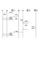
図4は、本実施形態の通信システム1における登録処理の動作の一例を示す図である。
(ステップS210)端末装置UEは、無線アクセスネットワークRANに対して「登録要求」を呼情報として通知する。この登録要求には、ネットワークスライスSLを指定する接続先情報が含まれている。
(ステップS220)無線アクセスネットワークRANは、複数の接続管理機能AMFのうちからランダムに選択された接続管理機能AMFに対して登録要求を転送する。この一例では、接続管理機能AMF1-1が登録要求の転送先として選択される。
図4は、本実施形態の通信システム1における登録処理の動作の一例を示す図である。
(ステップS210)端末装置UEは、無線アクセスネットワークRANに対して「登録要求」を呼情報として通知する。この登録要求には、ネットワークスライスSLを指定する接続先情報が含まれている。
(ステップS220)無線アクセスネットワークRANは、複数の接続管理機能AMFのうちからランダムに選択された接続管理機能AMFに対して登録要求を転送する。この一例では、接続管理機能AMF1-1が登録要求の転送先として選択される。
(ステップS230)接続管理機能AMF1-1は、端末装置UEの認証動作を行う。具体的には、接続管理機能AMF1-1は、ユニファイド・データ・マネージメントUDMが有する顧客データベースを参照する。
(ステップS240)ユニファイド・データ・マネージメントUDMは、接続管理機能AMF1-1に顧客データベースの参照結果を応答する。
(ステップS250)接続管理機能AMF1-1は、識別要求を端末装置UEに対して出力する。
(ステップS260)端末装置UEは、接続管理機能AMF1-1からの識別要求に対して応答する。この応答により、端末装置UEが認証される。
(ステップS240)ユニファイド・データ・マネージメントUDMは、接続管理機能AMF1-1に顧客データベースの参照結果を応答する。
(ステップS250)接続管理機能AMF1-1は、識別要求を端末装置UEに対して出力する。
(ステップS260)端末装置UEは、接続管理機能AMF1-1からの識別要求に対して応答する。この応答により、端末装置UEが認証される。
(ステップS270)接続管理機能AMF1-1は、ステップS220において無線アクセスネットワークRANから転送された登録要求を、呼情報保存ノードCISFに転送する。
(ステップS280)呼情報保存ノードCISFは、接続管理機能AMF1-1から転送された登録要求に含まれている接続先情報に基づいて、他の接続管理機能AMFに登録要求を転送する。この一例では、呼情報保存ノードCISFは、接続管理機能AMF2-1に対して登録要求を転送する。
(ステップS290)接続管理機能AMF2-1は、登録要求を受け取ったことを呼情報保存ノードCISFに応答する。
(ステップS300)呼情報保存ノードCISFは、接続先情報が示す他の接続管理機能AMFn-1に対して、登録要求を順次転送する。例えば、呼情報保存ノードCISFは、接続先情報が示す他の接続管理機能AMF3-1に対して、登録要求を転送する。
(ステップS310)接続管理機能AMFn-1は、登録要求を受け取ったことを呼情報保存ノードCISFに応答する。
呼情報保存ノードCISFは、接続先情報に示されるすべての接続管理機能AMFに登録要求を転送し終えるまで、ステップS300及びステップS310を繰り返す。
(ステップS280)呼情報保存ノードCISFは、接続管理機能AMF1-1から転送された登録要求に含まれている接続先情報に基づいて、他の接続管理機能AMFに登録要求を転送する。この一例では、呼情報保存ノードCISFは、接続管理機能AMF2-1に対して登録要求を転送する。
(ステップS290)接続管理機能AMF2-1は、登録要求を受け取ったことを呼情報保存ノードCISFに応答する。
(ステップS300)呼情報保存ノードCISFは、接続先情報が示す他の接続管理機能AMFn-1に対して、登録要求を順次転送する。例えば、呼情報保存ノードCISFは、接続先情報が示す他の接続管理機能AMF3-1に対して、登録要求を転送する。
(ステップS310)接続管理機能AMFn-1は、登録要求を受け取ったことを呼情報保存ノードCISFに応答する。
呼情報保存ノードCISFは、接続先情報に示されるすべての接続管理機能AMFに登録要求を転送し終えるまで、ステップS300及びステップS310を繰り返す。
(ステップS320)呼情報保存ノードCISFは、接続管理機能AMF2-1及び接続管理機能AMF3-1から応答を受け取ると、接続管理機能AMF1-1に対して登録要求に対しての応答をする。この応答は、接続先情報が示す各接続管理機能AMFに対する登録要求の転送が完了したことを示す。
(ステップS330)接続管理機能AMF1-1は、端末装置UEに対して登録要求の受付完了を通知する。
(ステップS340)端末装置UEは、接続管理機能AMF1-1に対して、登録要求の受付完了の通知についての応答を行い、一連の処理を終了する。この一連の処理により、端末装置UEが各接続管理機能AMFに登録要求をそれぞれ通知することなく、各接続管理機能AMFが登録要求を取得することができる。
(ステップS340)端末装置UEは、接続管理機能AMF1-1に対して、登録要求の受付完了の通知についての応答を行い、一連の処理を終了する。この一連の処理により、端末装置UEが各接続管理機能AMFに登録要求をそれぞれ通知することなく、各接続管理機能AMFが登録要求を取得することができる。
[(2)PDUセッション確立処理]
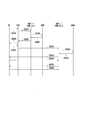
図5は、本実施形態の通信システム1におけるPDUセッション確立処理の動作の一例を示す図である。
(ステップS410)端末装置UEは、無線アクセスネットワークRANに対して「PDUセッション確立要求」を接続管理機能AMF1-1に転送する指示を、上述した呼情報として通知する。このPDUセッション確立要求には、接続対象のネットワークスライスSLを指定する接続先情報が含まれている。無線アクセスネットワークRANは、端末装置UEから指定された接続管理機能AMFに対してPDUセッション確立要求を転送する。この一例では、無線アクセスネットワークRANは、接続管理機能AMF1-1に対してPDUセッション確立要求を転送する。
図5は、本実施形態の通信システム1におけるPDUセッション確立処理の動作の一例を示す図である。
(ステップS410)端末装置UEは、無線アクセスネットワークRANに対して「PDUセッション確立要求」を接続管理機能AMF1-1に転送する指示を、上述した呼情報として通知する。このPDUセッション確立要求には、接続対象のネットワークスライスSLを指定する接続先情報が含まれている。無線アクセスネットワークRANは、端末装置UEから指定された接続管理機能AMFに対してPDUセッション確立要求を転送する。この一例では、無線アクセスネットワークRANは、接続管理機能AMF1-1に対してPDUセッション確立要求を転送する。
(ステップS420)接続管理機能AMF1-1は、ステップS420において無線アクセスネットワークRANから転送されたPDUセッション確立要求を、呼情報保存ノードCISFに転送する。
(ステップS430)呼情報保存ノードCISFは、接続管理機能AMF1-1から転送されたPDUセッション確立要求に含まれている接続先情報に基づいて、他の接続管理機能AMFにPDUセッション確立要求を転送する。この一例では、呼情報保存ノードCISFは、接続管理機能AMF2-1に対してPDUセッション確立要求を転送する。すなわち、呼情報保存ノードCISFは、接続管理機能AMF2-1に呼情報を転送する。
(ステップS440)接続管理機能AMF2-1は、PDUセッション確立要求を含むセッション管理要求をセッション・マネージメント・ファンクションSMF2に通知する。セッション・マネージメント・ファンクションSMF2は、ネットワークスライスSL2のセッション・マネージメント・ファンクションSMFである。
(ステップS450)セッション・マネージメント・ファンクションSMF2は、端末装置UEの認証動作を行う。具体的には、セッション・マネージメント・ファンクションSMF2は、ユニファイド・データ・マネージメントUDM2が有する顧客データベースを参照する。ユニファイド・データ・マネージメントUDM2は、ネットワークスライスSL2のユニファイド・データ・マネージメントUDMである。
(ステップS460)ユニファイド・データ・マネージメントUDM2は、セッション・マネージメント・ファンクションSMF2に顧客データベースの参照結果を応答する。
(ステップS470)セッション・マネージメント・ファンクションSMF2は、ポリシー・コントロール・ファンクションPCF2が有するQoS情報を参照する。ポリシー・コントロール・ファンクションPCF2は、ネットワークスライスSL2のポリシー・コントロール・ファンクションPCFである。
(ステップS480)ポリシー・コントロール・ファンクションPCF2は、セッション・マネージメント・ファンクションSMF2にQoS情報の参照結果を応答する。
(ステップS490)セッション・マネージメント・ファンクションSMF2は、ユーザー・プレーン・ファンクションUPF2に対して、N2PDUセッション要求を通知する。
(ステップS500)ユーザー・プレーン・ファンクションUPF2は、無線アクセスネットワークRANに対してN2PDUセッション要求を転送する。
(ステップS510)端末装置UE及び無線アクセスネットワークRANは、端末リソースのセットアップを行う。
(ステップS520)無線アクセスネットワークRANは、ユーザー・プレーン・ファンクションUPF2に対して、N2PDUセッション要求についての応答をする。
(ステップS530)ユーザー・プレーン・ファンクションUPF2は、セッション・マネージメント・ファンクションSMF2に対して、N2PDUセッション要求についての応答をする。
(ステップS540)セッション・マネージメント・ファンクションSMF2は、接続管理機能AMF2-1に対して、ステップS440において通知されたセッション管理要求に対する応答を行う。
(ステップS450)セッション・マネージメント・ファンクションSMF2は、端末装置UEの認証動作を行う。具体的には、セッション・マネージメント・ファンクションSMF2は、ユニファイド・データ・マネージメントUDM2が有する顧客データベースを参照する。ユニファイド・データ・マネージメントUDM2は、ネットワークスライスSL2のユニファイド・データ・マネージメントUDMである。
(ステップS460)ユニファイド・データ・マネージメントUDM2は、セッション・マネージメント・ファンクションSMF2に顧客データベースの参照結果を応答する。
(ステップS470)セッション・マネージメント・ファンクションSMF2は、ポリシー・コントロール・ファンクションPCF2が有するQoS情報を参照する。ポリシー・コントロール・ファンクションPCF2は、ネットワークスライスSL2のポリシー・コントロール・ファンクションPCFである。
(ステップS480)ポリシー・コントロール・ファンクションPCF2は、セッション・マネージメント・ファンクションSMF2にQoS情報の参照結果を応答する。
(ステップS490)セッション・マネージメント・ファンクションSMF2は、ユーザー・プレーン・ファンクションUPF2に対して、N2PDUセッション要求を通知する。
(ステップS500)ユーザー・プレーン・ファンクションUPF2は、無線アクセスネットワークRANに対してN2PDUセッション要求を転送する。
(ステップS510)端末装置UE及び無線アクセスネットワークRANは、端末リソースのセットアップを行う。
(ステップS520)無線アクセスネットワークRANは、ユーザー・プレーン・ファンクションUPF2に対して、N2PDUセッション要求についての応答をする。
(ステップS530)ユーザー・プレーン・ファンクションUPF2は、セッション・マネージメント・ファンクションSMF2に対して、N2PDUセッション要求についての応答をする。
(ステップS540)セッション・マネージメント・ファンクションSMF2は、接続管理機能AMF2-1に対して、ステップS440において通知されたセッション管理要求に対する応答を行う。
(ステップS550)接続管理機能AMF2-1は、呼情報保存ノードCISFに対して、ステップS430において通知されたPDUセッション確立要求に対する応答を行う。
他の接続先情報が示す接続管理機能AMFが更に存在する場合には、ステップS430~ステップS550の処理が繰り返される。
他の接続先情報が示す接続管理機能AMFが更に存在する場合には、ステップS430~ステップS550の処理が繰り返される。
(ステップS600)呼情報保存ノードCISFは、接続管理機能AMF1-1に対して、ステップS420において通知されたPDUセッション確立要求に対する応答を行う。すなわち、呼情報保存ノードCISFは、接続管理機能AMF1-1に対して、ネットワークスライスSL1以外のネットワークスライスSLについてのPDUセッション確立が完了したことを通知する。
(ステップS610~ステップS710)接続管理機能AMF1-1は、ネットワークスライスSL2において行われる上述したステップS440~ステップS540までの処理と同様の処理を、ネットワークスライスSL1において行う。これにより、接続管理機能AMF1-1には、セッション・マネージメント・ファンクションSMFから、ネットワークスライスSL1についてのPDUセッション確立が完了したことが通知される(ステップS710)。
(ステップS720)接続管理機能AMF1-1は、端末装置UEに対して各ネットワークスライスSLについてのPDUセッション確立が完了したことを通知する。この一連の処理により、端末装置UEが各接続管理機能AMFに対してPDUセッション確立要求をそれぞれ通知することなく、各ネットワークスライスSLにおいてPDUセッションを確立させることができる。
(ステップS720)接続管理機能AMF1-1は、端末装置UEに対して各ネットワークスライスSLについてのPDUセッション確立が完了したことを通知する。この一連の処理により、端末装置UEが各接続管理機能AMFに対してPDUセッション確立要求をそれぞれ通知することなく、各ネットワークスライスSLにおいてPDUセッションを確立させることができる。
[(3)ネットワークスライスリダイレクト処理]
図6は、本実施形態の通信システム1におけるネットワークスライスリダイレクト処理の動作の一例を示す図である。ここで、端末装置UEが接続しているネットワークスライスSLが変更されることがある。この場合、ネットワークスライスSLを管理するユニファイド・データ・マネージメントUDMは、無線アクセスネットワークRANに対して、端末装置UEが接続すべきネットワークスライスSLの識別情報(スライスID)を通知する。
図6は、本実施形態の通信システム1におけるネットワークスライスリダイレクト処理の動作の一例を示す図である。ここで、端末装置UEが接続しているネットワークスライスSLが変更されることがある。この場合、ネットワークスライスSLを管理するユニファイド・データ・マネージメントUDMは、無線アクセスネットワークRANに対して、端末装置UEが接続すべきネットワークスライスSLの識別情報(スライスID)を通知する。
(ステップS810)端末装置UEは、無線アクセスネットワークRANに対して「登録要求」を呼情報として通知する。この登録要求には、ネットワークスライスSLを指定する接続先情報が含まれている。
(ステップS820)無線アクセスネットワークRANは、予め登録されている接続管理機能AMFに対して登録要求を転送する。この一例では、接続管理機能AMF1-1が接続先の接続管理機能AMFとして登録されている。この一例の場合、無線アクセスネットワークRANは、接続管理機能AMF1-1に対して登録要求を転送する。
(ステップS830)接続管理機能AMF1-1は、端末装置UEの認証動作を行う。具体的には、接続管理機能AMF1-1は、ユニファイド・データ・マネージメントUDMが有する顧客データベースを参照する。
(ステップS840)ユニファイド・データ・マネージメントUDMは、接続管理機能AMF1-1に顧客データベースの参照結果を応答する。この応答には、リダイレクト指示とスライスIDとが含まれている。
(ステップS850)接続管理機能AMF1-1は、無線アクセスネットワークRANに対して、リダイレクト通知を行う。このリダイレクト通知には、ステップS840においてユニファイド・データ・マネージメントUDMから通知されたスライスIDが含まれている。
(ステップS860)無線アクセスネットワークRANは、端末装置UEに対して、接続管理機能AMF1-1から通知されたリダイレクト通知を転送する。この一連の処理により、無線アクセスネットワークRANには端末装置UEが接続すべきネットワークスライスSLのスライスIDが登録される。
(ステップS820)無線アクセスネットワークRANは、予め登録されている接続管理機能AMFに対して登録要求を転送する。この一例では、接続管理機能AMF1-1が接続先の接続管理機能AMFとして登録されている。この一例の場合、無線アクセスネットワークRANは、接続管理機能AMF1-1に対して登録要求を転送する。
(ステップS830)接続管理機能AMF1-1は、端末装置UEの認証動作を行う。具体的には、接続管理機能AMF1-1は、ユニファイド・データ・マネージメントUDMが有する顧客データベースを参照する。
(ステップS840)ユニファイド・データ・マネージメントUDMは、接続管理機能AMF1-1に顧客データベースの参照結果を応答する。この応答には、リダイレクト指示とスライスIDとが含まれている。
(ステップS850)接続管理機能AMF1-1は、無線アクセスネットワークRANに対して、リダイレクト通知を行う。このリダイレクト通知には、ステップS840においてユニファイド・データ・マネージメントUDMから通知されたスライスIDが含まれている。
(ステップS860)無線アクセスネットワークRANは、端末装置UEに対して、接続管理機能AMF1-1から通知されたリダイレクト通知を転送する。この一連の処理により、無線アクセスネットワークRANには端末装置UEが接続すべきネットワークスライスSLのスライスIDが登録される。
(ステップS910)端末装置UEは、無線アクセスネットワークRANからリダイレクト通知を受けると、新たな接続先であるネットワークスライスSL2に対して、登録要求を通知する。具体的には、端末装置UEは、無線アクセスネットワークRANに対して「登録要求」を呼情報として通知する。この登録要求には、ネットワークスライスSLを指定する接続先情報が含まれている。
(ステップS920)無線アクセスネットワークRANは、接続管理機能AMF2-1に対して登録要求を転送する。
(ステップS930)接続管理機能AMF2-1は、端末装置UEの認証動作を行う。具体的には、接続管理機能AMF2-1は、ユニファイド・データ・マネージメントUDM2が有する顧客データベースを参照する。
(ステップS940)ユニファイド・データ・マネージメントUDM2は、接続管理機能AMF2-1に顧客データベースの参照結果を応答する。
(ステップS950)接続管理機能AMF2-1は、識別要求を端末装置UEに対して出力する。
(ステップS960)端末装置UEは、接続管理機能AMF2-1からの識別要求に対して応答する。この応答により、端末装置UEが認証される。
(ステップS970)接続管理機能AMF2-1は、端末装置UEに対して登録要求の受付完了を通知する。
(ステップS980)端末装置UEは、接続管理機能AMF2-1に対して、登録要求の受付完了の通知についての応答を行い、一連の処理を終了する。この一連の処理により、接続先のネットワークスライスSLが変更された場合に、呼情報保存ノードCISFが呼情報を転送する環境においても、端末装置UEが各接続管理機能AMFに登録要求をそれぞれ通知することなく、各接続管理機能AMFが登録要求を取得することができる。
(ステップS920)無線アクセスネットワークRANは、接続管理機能AMF2-1に対して登録要求を転送する。
(ステップS930)接続管理機能AMF2-1は、端末装置UEの認証動作を行う。具体的には、接続管理機能AMF2-1は、ユニファイド・データ・マネージメントUDM2が有する顧客データベースを参照する。
(ステップS940)ユニファイド・データ・マネージメントUDM2は、接続管理機能AMF2-1に顧客データベースの参照結果を応答する。
(ステップS950)接続管理機能AMF2-1は、識別要求を端末装置UEに対して出力する。
(ステップS960)端末装置UEは、接続管理機能AMF2-1からの識別要求に対して応答する。この応答により、端末装置UEが認証される。
(ステップS970)接続管理機能AMF2-1は、端末装置UEに対して登録要求の受付完了を通知する。
(ステップS980)端末装置UEは、接続管理機能AMF2-1に対して、登録要求の受付完了の通知についての応答を行い、一連の処理を終了する。この一連の処理により、接続先のネットワークスライスSLが変更された場合に、呼情報保存ノードCISFが呼情報を転送する環境においても、端末装置UEが各接続管理機能AMFに登録要求をそれぞれ通知することなく、各接続管理機能AMFが登録要求を取得することができる。
[比較例の技術との比較]
図7は、比較例の技術による複数のネットワークスライスSLへの接続の一例を示す図である。この比較例の技術の場合、端末装置UEは、ユーザー・プレーン・ファンクションUPFとの間において、ユーザデータPU1~PU3をやり取りする。
この比較例の技術においては、端末装置UEが複数のネットワークスライスSLに接続する場合、端末装置UEは、各ネットワークスライスSLの接続管理機能AMFに対して直接、呼情報を通知していた。具体的には、同図に示すように、端末装置UEが三つのネットワークスライスSLに接続する場合、端末装置UEは、接続管理機能AMF1-1に対して呼情報PC1を、接続管理機能AMF2-1に対して呼情報PC2を、接続管理機能AMF3-1に対して呼情報PC3をそれぞれ通知していた。
ところが、この比較例の技術によると、端末装置UEが接続すべきネットワークスライスSLが増えれば増えるほど、無線リソースの消費量が増大するという問題がある。またこの比較例の技術によると、端末装置UEが各ネットワークスライスSLにそれぞれ呼情報を通知するため、端末装置UEの消費電力が増大してしまうという問題がある。また、端末装置UEがバッテリー駆動の場合には、動作可能時間が短くなってしまうという問題がある。
図7は、比較例の技術による複数のネットワークスライスSLへの接続の一例を示す図である。この比較例の技術の場合、端末装置UEは、ユーザー・プレーン・ファンクションUPFとの間において、ユーザデータPU1~PU3をやり取りする。
この比較例の技術においては、端末装置UEが複数のネットワークスライスSLに接続する場合、端末装置UEは、各ネットワークスライスSLの接続管理機能AMFに対して直接、呼情報を通知していた。具体的には、同図に示すように、端末装置UEが三つのネットワークスライスSLに接続する場合、端末装置UEは、接続管理機能AMF1-1に対して呼情報PC1を、接続管理機能AMF2-1に対して呼情報PC2を、接続管理機能AMF3-1に対して呼情報PC3をそれぞれ通知していた。
ところが、この比較例の技術によると、端末装置UEが接続すべきネットワークスライスSLが増えれば増えるほど、無線リソースの消費量が増大するという問題がある。またこの比較例の技術によると、端末装置UEが各ネットワークスライスSLにそれぞれ呼情報を通知するため、端末装置UEの消費電力が増大してしまうという問題がある。また、端末装置UEがバッテリー駆動の場合には、動作可能時間が短くなってしまうという問題がある。
一方、本実施形態の通信システム1によれば、端末装置UEが各ネットワークスライスSLに呼情報を通知しなくても、各ネットワークスライスSLに対して呼情報が通知される仕組みを有している。したがって、本実施形態の通信システム1によれば、端末装置UEが接続すべきネットワークスライスSLが増えたとしても、端末装置UEとネットワークスライスSLとの間の無線リソースの消費量が増えない。また、本実施形態の通信システム1によれば、端末装置UEがネットワークスライスSLに対して呼情報を通知する頻度が比較例の技術に比べて低下する。このため、端末装置UEの電力の消費を抑制することができる。つまり、本実施形態の通信システム1によれば、接続すべきネットワークスライスSL数の増加による無線リソースの消費や端末装置の電力の消費を抑制することができる。
なお、本実施形態の呼情報には、スライスID、信号処理を実施した接続管理機能AMFのIPアドレス、端末装置UEとNAS(Non Access Stratum)との間において信号処理を実施するための暗号鍵や、IMSI(International Mobile Subscriber Identity)などの識別子、端末が保持している場合はIPアドレス、無線アクセスネットワークRANのIPアドレス、端末が接続しているcellやTA(Tracking Area)といった情報が含まれる。
以上、本発明の実施形態及びその変形を説明したが、これらの実施形態及びその変形は、例として提示したものであり、発明の範囲を限定することは意図していない。これら実施形態及びその変形は、その他の様々な形態で実施されることが可能であり、発明の要旨を逸脱しない範囲で、種々の省略、置き換え、変更を行うことができる。これら実施形態及びその変形は、発明の範囲や要旨に含まれると同時に、特許請求の範囲に記載された発明とその均等の範囲に含まれるものである。
なお、上述の各装置は内部にコンピュータを有している。そして、上述した各装置の各処理の過程は、プログラムの形式でコンピュータ読み取り可能な記録媒体に記憶されており、このプログラムをコンピュータが読み出して実行することによって、上記処理が行われる。ここでコンピュータ読み取り可能な記録媒体とは、磁気ディスク、光磁気ディスク、CD-ROM、DVD-ROM、半導体メモリ等をいう。また、このコンピュータプログラムを通信回線によってコンピュータに配信し、この配信を受けたコンピュータが当該プログラムを実行するようにしてもよい。
また、上記プログラムは、前述した機能の一部を実現するためのものであってもよい。
さらに、前述した機能をコンピュータシステムにすでに記録されているプログラムとの組み合わせで実現できるもの、いわゆる差分ファイル(差分プログラム)であってもよい。
さらに、前述した機能をコンピュータシステムにすでに記録されているプログラムとの組み合わせで実現できるもの、いわゆる差分ファイル(差分プログラム)であってもよい。
本発明によれば、接続先のネットワークスライス数の増加による無線リソースの消費や端末装置の電力の消費を抑制することができる端末装置、通信システム及び通信装置を提供することができる。
1…通信システム、110…通知部、120…故障情報受信部、130…第2通知部、210…接続管理部、220…呼情報受信部、230…呼情報通知部、310…呼情報取得部、320…呼情報転送部、UE…端末装置、AMF…接続管理機能、CISF…呼情報保存ノード、SL…ネットワークスライス(コアネットワークスライス)
Claims (7)
- 複数のネットワークスライスのうち、端末装置から第1のネットワークスライスに対して通知された呼情報に含まれる接続先情報が示すネットワークスライスに、前記呼情報を転送する呼情報転送部を備える通信装置に対して、前記第1のネットワークスライス以外の第2のネットワークスライスを接続先として示す前記接続先情報を含む前記呼情報を、前記第1のネットワークスライスに対して通知する通知部
を備える端末装置。 - 複数のネットワークスライスのうち、いずれかのネットワークスライスから前記呼情報転送部の故障を示す情報を受信する故障情報受信部と、
前記故障情報受信部が受信する前記故障を示す情報に基づいて、前記第2のネットワークスライスに対して呼情報を通知する第2通知部
をさらに備える請求項1に記載の端末装置。 - 前記呼情報には、ネットワークスライスに含まれる複数のセッションのうち、接続先のセッションを示す情報がさらに含まれる
請求項1又は請求項2に記載の端末装置。 - ネットワークスライスと端末装置との無線通信の接続を管理する管理部と、
複数のネットワークスライスのうち、前記端末装置から第1のネットワークスライスを管理する第1の接続管理部に対して通知された呼情報に含まれる接続先情報が示すネットワークスライスを管理する前記管理部に対して、前記第1の接続管理部に通知された前記呼情報を転送する呼情報転送部と、
複数のネットワークスライスのうち、前記第1のネットワークスライス以外の接続先である第2のネットワークスライスを接続先として示す前記接続先情報を含む前記呼情報を、前記第1の接続管理部に対して通知する通知部を備える端末装置と
を備える通信システム。 - 前記呼情報転送部は、
前記呼情報に含まれる前記接続先情報が示すネットワークスライスを管理する前記接続管理部に対して前記呼情報を転送した後に、前記第1の接続管理部からの前記呼情報の通知に対する応答を行う
請求項4に記載の通信システム。 - 複数のネットワークスライスのうち、いずれかのネットワークスライスを接続先として示す接続先情報を含む呼情報を端末装置から受信する呼情報受信部と、
通知された前記呼情報に含まれる前記接続先情報が示すネットワークスライスに前記呼情報を転送する呼情報転送部に対して、前記呼情報受信部が受信した前記呼情報を通知する呼情報通知部
を備える通信装置。 - 複数のネットワークスライスのうち、端末装置から第1のネットワークスライスに対して通知された呼情報を、前記第1のネットワークスライスを管理する接続管理部から取得する呼情報取得部と、
複数のネットワークスライスのうち、前記呼情報取得部が取得する前記呼情報に含まれる接続先情報が示す第2のネットワークスライスを管理する第2の接続管理部に対して、取得された前記呼情報を転送する呼情報転送部と、
を備える通信装置。
Applications Claiming Priority (2)
| Application Number | Priority Date | Filing Date | Title |
|---|---|---|---|
| JP2017-069229 | 2017-03-30 | ||
| JP2017069229A JP6798919B2 (ja) | 2017-03-30 | 2017-03-30 | 端末装置、通信システム及び通信装置 |
Publications (1)
| Publication Number | Publication Date |
|---|---|
| WO2018180871A1 true WO2018180871A1 (ja) | 2018-10-04 |
Family
ID=63675627
Family Applications (1)
| Application Number | Title | Priority Date | Filing Date |
|---|---|---|---|
| PCT/JP2018/011368 Ceased WO2018180871A1 (ja) | 2017-03-30 | 2018-03-22 | 端末装置、通信システム及び通信装置 |
Country Status (2)
| Country | Link |
|---|---|
| JP (1) | JP6798919B2 (ja) |
| WO (1) | WO2018180871A1 (ja) |
Cited By (2)
| Publication number | Priority date | Publication date | Assignee | Title |
|---|---|---|---|---|
| US20220394608A1 (en) * | 2020-02-17 | 2022-12-08 | Huawei Technologies Co., Ltd. | Communication method and communication apparatus |
| EP4090071A4 (en) * | 2020-01-23 | 2023-01-25 | Huawei Technologies Co., Ltd. | METHOD AND DEVICE FOR REDIRECTING NETWORK SLICES |
Citations (2)
| Publication number | Priority date | Publication date | Assignee | Title |
|---|---|---|---|---|
| JP2016201602A (ja) * | 2015-04-07 | 2016-12-01 | 株式会社Nttドコモ | 通信システム及び通信方法 |
| WO2016192636A1 (en) * | 2015-06-01 | 2016-12-08 | Huawei Technologies Co., Ltd. | System and method for virtualized functions in control and data planes |
-
2017
- 2017-03-30 JP JP2017069229A patent/JP6798919B2/ja active Active
-
2018
- 2018-03-22 WO PCT/JP2018/011368 patent/WO2018180871A1/ja not_active Ceased
Patent Citations (2)
| Publication number | Priority date | Publication date | Assignee | Title |
|---|---|---|---|---|
| JP2016201602A (ja) * | 2015-04-07 | 2016-12-01 | 株式会社Nttドコモ | 通信システム及び通信方法 |
| WO2016192636A1 (en) * | 2015-06-01 | 2016-12-08 | Huawei Technologies Co., Ltd. | System and method for virtualized functions in control and data planes |
Cited By (3)
| Publication number | Priority date | Publication date | Assignee | Title |
|---|---|---|---|---|
| EP4090071A4 (en) * | 2020-01-23 | 2023-01-25 | Huawei Technologies Co., Ltd. | METHOD AND DEVICE FOR REDIRECTING NETWORK SLICES |
| US12335741B2 (en) | 2020-01-23 | 2025-06-17 | Huawei Technologies Co., Ltd. | Network slice redirection method and apparatus |
| US20220394608A1 (en) * | 2020-02-17 | 2022-12-08 | Huawei Technologies Co., Ltd. | Communication method and communication apparatus |
Also Published As
| Publication number | Publication date |
|---|---|
| JP6798919B2 (ja) | 2020-12-09 |
| JP2018170748A (ja) | 2018-11-01 |
Similar Documents
| Publication | Publication Date | Title |
|---|---|---|
| CN109951824B (zh) | 通信方法及装置 | |
| US20240372869A1 (en) | Method for implementing user plane security policy, apparatus, and system | |
| US12238632B2 (en) | Service configuration method, communication apparatus, and communication system | |
| KR102224248B1 (ko) | 통신 시스템에서 PDU(Protocol Data Unit) 세션을 설립하는 방법 | |
| KR102412288B1 (ko) | 제 3자 응용 서버에서 단말의 무선 연결 타입 변경을 확인하는 방법 | |
| JP6202416B2 (ja) | 分散進化型パケットコアアーキテクチャのためのシステムおよび方法 | |
| JP2023029917A (ja) | セッション管理の方法、装置、およびシステム | |
| US20230247094A1 (en) | Methods, architectures, apparatuses and systems directed to transaction management in blockchain-enabled wireless systems | |
| EP3499965A1 (en) | Communication system, communication device, and program | |
| CN110291837A (zh) | 网络注册和网络切片选择系统和方法 | |
| JP2019525506A (ja) | 登録方法、セッション確立方法、端末、およびamfエンティティ | |
| US12317077B2 (en) | Communication system | |
| US20240048986A1 (en) | Communication method and apparatus | |
| CN112954768B (zh) | 通信方法、装置及系统 | |
| CN111801961A (zh) | 一种确定ssc模式的方法及装置 | |
| US20160353498A1 (en) | Communication control method, position management device, base station device, terminal device, and communication system | |
| US12219087B2 (en) | Systems and methods for regional segmentation and selection of charging function | |
| CN108810988B (zh) | 一种消息传输的方法及装置 | |
| TW202442005A (zh) | Musim裝置的不可用性週期支援 | |
| WO2024169556A1 (zh) | 一种网元选择方法及装置 | |
| US11510257B2 (en) | Communications method and apparatus | |
| TW202442006A (zh) | 與擁塞相關聯的不可用性週期支援 | |
| JP6798919B2 (ja) | 端末装置、通信システム及び通信装置 | |
| CN112005580B (zh) | 边缘服务连续性 | |
| CN111757313A (zh) | 一种通信方法及装置 |
Legal Events
| Date | Code | Title | Description |
|---|---|---|---|
| 121 | Ep: the epo has been informed by wipo that ep was designated in this application |
Ref document number: 18776921 Country of ref document: EP Kind code of ref document: A1 |
|
| NENP | Non-entry into the national phase |
Ref country code: DE |
|
| 122 | Ep: pct application non-entry in european phase |
Ref document number: 18776921 Country of ref document: EP Kind code of ref document: A1 |