WO2018170843A1 - Electrochemical surface cleaning and plating - Google Patents
Electrochemical surface cleaning and plating Download PDFInfo
- Publication number
- WO2018170843A1 WO2018170843A1 PCT/CN2017/077893 CN2017077893W WO2018170843A1 WO 2018170843 A1 WO2018170843 A1 WO 2018170843A1 CN 2017077893 W CN2017077893 W CN 2017077893W WO 2018170843 A1 WO2018170843 A1 WO 2018170843A1
- Authority
- WO
- WIPO (PCT)
- Prior art keywords
- salt solution
- electrode
- nickel
- voltage
- nickel salt
- Prior art date
- Legal status (The legal status is an assumption and is not a legal conclusion. Google has not performed a legal analysis and makes no representation as to the accuracy of the status listed.)
- Ceased
Links
Images
Classifications
-
- C—CHEMISTRY; METALLURGY
- C25—ELECTROLYTIC OR ELECTROPHORETIC PROCESSES; APPARATUS THEREFOR
- C25D—PROCESSES FOR THE ELECTROLYTIC OR ELECTROPHORETIC PRODUCTION OF COATINGS; ELECTROFORMING; APPARATUS THEREFOR
- C25D5/00—Electroplating characterised by the process; Pretreatment or after-treatment of workpieces
- C25D5/18—Electroplating using modulated, pulsed or reversing current
-
- C—CHEMISTRY; METALLURGY
- C23—COATING METALLIC MATERIAL; COATING MATERIAL WITH METALLIC MATERIAL; CHEMICAL SURFACE TREATMENT; DIFFUSION TREATMENT OF METALLIC MATERIAL; COATING BY VACUUM EVAPORATION, BY SPUTTERING, BY ION IMPLANTATION OR BY CHEMICAL VAPOUR DEPOSITION, IN GENERAL; INHIBITING CORROSION OF METALLIC MATERIAL OR INCRUSTATION IN GENERAL
- C23G—CLEANING OR DE-GREASING OF METALLIC MATERIAL BY CHEMICAL METHODS OTHER THAN ELECTROLYSIS
- C23G1/00—Cleaning or pickling metallic material with solutions or molten salts
-
- C—CHEMISTRY; METALLURGY
- C23—COATING METALLIC MATERIAL; COATING MATERIAL WITH METALLIC MATERIAL; CHEMICAL SURFACE TREATMENT; DIFFUSION TREATMENT OF METALLIC MATERIAL; COATING BY VACUUM EVAPORATION, BY SPUTTERING, BY ION IMPLANTATION OR BY CHEMICAL VAPOUR DEPOSITION, IN GENERAL; INHIBITING CORROSION OF METALLIC MATERIAL OR INCRUSTATION IN GENERAL
- C23G—CLEANING OR DE-GREASING OF METALLIC MATERIAL BY CHEMICAL METHODS OTHER THAN ELECTROLYSIS
- C23G1/00—Cleaning or pickling metallic material with solutions or molten salts
- C23G1/02—Cleaning or pickling metallic material with solutions or molten salts with acid solutions
- C23G1/10—Other heavy metals
-
- C—CHEMISTRY; METALLURGY
- C25—ELECTROLYTIC OR ELECTROPHORETIC PROCESSES; APPARATUS THEREFOR
- C25D—PROCESSES FOR THE ELECTROLYTIC OR ELECTROPHORETIC PRODUCTION OF COATINGS; ELECTROFORMING; APPARATUS THEREFOR
- C25D21/00—Processes for servicing or operating cells for electrolytic coating
- C25D21/12—Process control or regulation
-
- C—CHEMISTRY; METALLURGY
- C25—ELECTROLYTIC OR ELECTROPHORETIC PROCESSES; APPARATUS THEREFOR
- C25D—PROCESSES FOR THE ELECTROLYTIC OR ELECTROPHORETIC PRODUCTION OF COATINGS; ELECTROFORMING; APPARATUS THEREFOR
- C25D5/00—Electroplating characterised by the process; Pretreatment or after-treatment of workpieces
- C25D5/34—Pretreatment of metallic surfaces to be electroplated
- C25D5/38—Pretreatment of metallic surfaces to be electroplated of refractory metals or nickel
-
- C—CHEMISTRY; METALLURGY
- C25—ELECTROLYTIC OR ELECTROPHORETIC PROCESSES; APPARATUS THEREFOR
- C25F—PROCESSES FOR THE ELECTROLYTIC REMOVAL OF MATERIALS FROM OBJECTS; APPARATUS THEREFOR
- C25F1/00—Electrolytic cleaning, degreasing, pickling or descaling
-
- C—CHEMISTRY; METALLURGY
- C25—ELECTROLYTIC OR ELECTROPHORETIC PROCESSES; APPARATUS THEREFOR
- C25F—PROCESSES FOR THE ELECTROLYTIC REMOVAL OF MATERIALS FROM OBJECTS; APPARATUS THEREFOR
- C25F3/00—Electrolytic etching or polishing
-
- C—CHEMISTRY; METALLURGY
- C25—ELECTROLYTIC OR ELECTROPHORETIC PROCESSES; APPARATUS THEREFOR
- C25F—PROCESSES FOR THE ELECTROLYTIC REMOVAL OF MATERIALS FROM OBJECTS; APPARATUS THEREFOR
- C25F7/00—Constructional parts, or assemblies thereof, of cells for electrolytic removal of material from objects; Servicing or operating
-
- C—CHEMISTRY; METALLURGY
- C25—ELECTROLYTIC OR ELECTROPHORETIC PROCESSES; APPARATUS THEREFOR
- C25D—PROCESSES FOR THE ELECTROLYTIC OR ELECTROPHORETIC PRODUCTION OF COATINGS; ELECTROFORMING; APPARATUS THEREFOR
- C25D3/00—Electroplating: Baths therefor
- C25D3/02—Electroplating: Baths therefor from solutions
- C25D3/12—Electroplating: Baths therefor from solutions of nickel or cobalt
Definitions
- the present invention relates to a cleaning and plating method for a nickel (Ni) -based alloy member, and more specifically, to a method for cleaning organics and metal oxides from the surface and near surface of a Ni-based superalloy and subsequently forming a plating layer on the surface of the nickel-titanium alloy member.
- Ni-based superalloys also known as high-performance alloys exhibit many desirable characteristics including excellent mechanical strength, resistance to thermal creep deformation, good surface stability, and resistance to corrosion or oxidation.
- high performance components such as turbine blades are often formed of relatively highly alloyed Ni superalloys, and in particular those that include relatively large amounts of aluminum (Al) and titanium (Ti) . While of significant help and necessary in strengthening Ni superalloys, during manufacture Al and Ti can form relatively large and tenacious amounts of surface and near surface (e.g., subsurface) oxides.
- Ni superalloy members Typical attachment mechanisms for Ni superalloy members to other members include welding, diffusion bonding, and brazing.
- the design of certain Ni superalloy gas turbine blades specifies that an end plate or tip plate be secured at an inner wall of the open blade end.
- metal oxides at or near the joining surface of such Ni superalloy members can interfere with the soundness and integrity of the joint.
- Al and Ti oxides at or near the surface of a member can not only interfere with the adhesion of a plating layer to the member surface but can also interfere with the flow of brazing alloys at the surface following plating.
- Ni-based alloy members that can provide excellent surface cleaning.
- systems and methods for plating the cleaned surfaces that avoid re-oxidation of the surfaces prior to the plating. Such methods can provide for improved joining of Ni-based alloy members via, e.g., brazing.
- a method for plating a surface for instance a Ni superalloy surface of a gas turbine blade.
- a method can include submerging the surface in a nickel salt solution.
- An electrode can also be submerged in the nickel salt solution and a first voltage can be established across the nickel salt solution between the Ni superalloy surface and the electrode.
- the first voltage is established such that the Ni superalloy surface is at a higher electrical potential (positive voltage) relative to the electrode.
- the surface can be electrochemically etched, causing depletion of metal oxides at or near the surface.
- the polarity of the electrode and the surface can be reversed, i.e., a second voltage can be established across the nickel salt solution between the Ni superalloy surface and the electrode such that the Ni superalloy surface is now at a lower electrical potential (negative voltage) relative to the electrode.
- nickel present in the system for instance nickel ions of the salt solution and/or nickel of the electrode
- the Ni superalloy surface can be cleaned of oxides and plated in situ, without any contact between an oxygen-containing atmosphere and the surface following etching and prior to Ni plating.
- a method can include additional optional components as desired.
- a method can include acid surface cleaning prior to the electrochemical etching step and/or electrochemical cleaning prior to the electrochemical etching step.
- a method can include removal of any dissolved oxygen from the nickel salt solution prior to the electrochemical etching, for instance by bubbling nitrogen through the nickel salt solution.
- the surface can be joined to another member via, e.g., brazing.
- a system can include a nickel salt bath, an electrode configured for submersion in the nickel salt bath, a power source in electrical communication with the electrode, and a controller configured to sequentially establish voltages of opposite polarity across the nickel salt solution.
- a system can include additional components as well, such as a sodium salt solution bath and/or one or more acid etchant baths upstream of the nickel salt solution bath, washing stations located between baths, and the like.
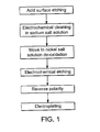
- FIG. 1 is a flow diagram presenting one embodiment of disclosed methods.
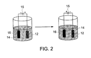
- FIG. 2 schematically illustrates sequential electrochemical etching and electroplating operations in a single electrochemical solution.
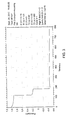
- FIG. 3 graphically illustrates the electrical characteristics of a system over the course of an electrochemical etch followed by electrochemical plating in a single electrochemical solution.
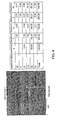
- FIG. 4 provides content information at various locations of a plated surface.
- the present disclosure is directed to methods and systems for preparing the surface of Ni-based alloys for joining. More specifically, the methods include both removal of surface and near surface metal oxides and subsequent nickel plating of the surface by use of a single immersion solution.
- the methods and systems can provide a route for removal of essentially all metal oxides from the surface and near surface and can avoid re-oxidation of the surface prior to plating.
- the methods are directed to cleaning and plating Ni superalloy surfaces.
- the higher temperatures designed for components in the hot or turbine sections of current gas turbine engines require use of more highly alloyed superalloys, mostly based on Ni.
- such alloys as the Ni superalloys include relatively large amounts (e.g., about 5 wt. %or more) of one or more of the gamma prime strengtheners Al and Ti, , along with a variety of other elements, as widely described in the literature.
- Typical Ni superalloys such as those used in current gas turbine engine turbine components include Rene'80 alloy, more fully described in U.S. Pat. No. 3,615,376 to Ross (patented Oct.
- such alloy can include about 0.75%Hf.
- Rene'125 alloy Another Ni superalloy used to make such components is commonly referred to as Rene'125 alloy, including nominally by weight about: 10%Co, 4.8%Al, 9%Cr, 2.5%Ti, 3.8%Ta, 7%W, 2%Mo, 1.5%Hf, 0.11%C, 0.01%B, 0.05%Zr, with the balance Ni and incidental impurities.
- Still another Ni base superalloy, generally made substantially in single crystal form and referred to as Rene'N4 alloy includes nominally by weight about: 7.5%Co, 9%Cr, 3.5%Al, 4.8%Ti, 1.5%Mo, 4%Ta, 6%W, 0.004%C, 0.5%Cb, with the balance Ni and incidental impurities. All of such alloys include relatively large amounts of the gamma prime strengtheners Al and Ti.
- a first step of a surface preparation process can include acid etching, also referred to as acid pickling.
- the acid etching can remove material from the surface and near surface including metal oxides of the member as well as organic material present on the surface, while avoiding potentially detrimental intergranular attach of the substrate.
- a process can also include a surface abrading step (not shown in FIG. 1) that can generally be carried out prior to the acid etching step.
- a surface abrading step can be carried out according to known methodology, such as by tumbling the member in conjunction with an abrasive medium or slurry, by vapor blasting, or by a combination of such operations.
- Acid etching can utilize one or multiple acid baths.
- acid etching of a member having an alloy content of greater than about 6% such as a Ni superalloy member can generally be carried out in a two-step process.
- all or a portion of a member i.e., at least the Ni-based alloy surface to be plated
- a first etching solution that includes a mixture of nitric acid and sulfuric acid.
- an aqueous solution can include sulfuric acid in an amount of from about 20 wt. %to about 30 wt. %, or about 25 wt. %in one embodiment, and can include nitric acid in an amount of from about 10 wt. %to about 15 wt. %, for instance about 12.5 wt. %in one embodiment.
- a second acid etching solution can include hydrochloric acid, for instance an aqueous hydrochloric acid solution including hydrochloric acid in an amount of from about 20 wt. %to about 25 wt. %, for instance about 23 wt. %in some embodiments.
- a hydrochloric acid etching solution can have a chloride ion concentration of about 0.1 mol/L or more, about 0.3 mol/L or more, or about 0.4 mol/l or more in some embodiments, and can have a pH value of about 2 or less.
- the member can be submerged in the solution (s) for a period of time so as to remove any organic material.
- an acid etching step can also remove a portion of the metal oxides at or near the surface.
- a surface can be submerged for a period of from about 1 minute to about 5 minutes in each acid etching solution, e.g., about 1 minute to about 5 minutes (e.g., about 2 minutes) in a H 2 SO 4 /HNO 3 solution followed by about 1 minute to about 5 minutes (e.g., about 2 minutes) in a HCl solution.
- One or both of the acid etching solutions can optionally include components having a high oxidizing power (optionally used in combination with one another) such as, and without limitation to, permanganates, persulphates, ferric chloride, ferric sulphate and/or hydrogen peroxide.
- a high oxidizing power such as, and without limitation to, permanganates, persulphates, ferric chloride, ferric sulphate and/or hydrogen peroxide.
- An acid etching solution can generally be heated, for instance with solution temperatures during etching generally from about 50°C to about 100°, from about 50°C to about 85°C, or from about 60°C to about 75°C in some embodiments.
- the surface can be washed, for instance by use of a water jet system equipped with rotary brushes as is known in the art.
- a washing step between operations of the process can remove solution that may be carried to the next operation as well as removal of metal and oxides that have been separated from the bulk structure surface.
- the surface can be electrochemically cleaned to remove any remaining surface contaminants such as organics (e.g., greases) .
- this can be carried out by electrochemically cleaning the member in a sodium salt solution.
- the submerged surface can be limited to just the joining surfaces (e.g., the surface that will be bonded in a brazed joint) .
- the sodium salt solution can generally include any sodium salt or mixture thereof as is known in the art.
- the sodium salt solution can include a eutectic mixture of a NaOH-NaNO 3 -NaCl ternary system (sometimes referred to as a Kolene bath) .
- the sodium salt solution may be a sodium sulphate (Na 2 SO 4 ) neutral aqueous solution having a concentration ranging from 25 g/L to 300 g/L.
- the sodium salt solution can generally be heated to a temperature suitable to melt the salts, for instance to a temperature of from about 400°C to about 600°C, or about 500°C in some embodiments.
- an electrode can be submerged in the sodium salt solution and an electrical potential can be established across the sodium salt solution and between the surface to be cleaned and the electrode.
- Any electrode as is known in the art e.g., a solid nickel electrode or the like
- the same type of electrode can be used in both the electrochemical cleaning process and the subsequent electrochemical etching and plating processes. This is not a requirement of the methods, however.
- An electric potential can be established across the sodium salt solution such that the surface to be cleaned is at a lower potential relative to the electrode (i.e., the surface is set as the cathode) .
- the electrochemical cleaning can be carried out upon establishment of a suitable current density in the system.
- the electrochemical etching can generally be carried out at a current density having an effective amplitude ranging from about 10 amps per square decimeter (A/dm 2 ) to about 250 A/dm 2 , for instance from about 3 A/dm 2 to about 40 A/dm 2 in some embodiments.
- the member can be removed from the sodium salt solution and washed as described above prior to the member (or at least the surface of interest) being submerged in a nickel salt solution.
- the nickel salt solution can generally include any nickel salt or mixture thereof capable of increasing the degree of oxidation of the metals constituting the oxides at or near the submerged surface.
- a nickel sulfate salt, a nickel chloride salt, or a combination of nickel salts can be included in the nickel salt solution.
- the nickel salt solution can be an acid nickel salt solution, e.g. a boric acid solution including about 60 wt. %or more of one or more nickel salts, for instance from about 75 wt. %to about 95 wt. %nickel salts, or about 80 wt. %to about 90 wt. %in some embodiments.
- the sodium salt solution can generally be heated to a temperature suitable to melt the salts, for instance to a temperature of from about 50°C to about 100°C, or about 60°C in some embodiments.
- the nickel salt solution can function as the medium for both the electrochemical etching of the surface as well as the subsequent electrochemical plating of the surface.
- the member need not contact the surrounding atmosphere again until after the plating process is completed, which can prevent re-oxidation of the surface and improve subsequent joints formed at the plated surface.
- dissolved oxygen can be removed from the nickel salt solution.
- nitrogen (N 2 ) can be bubbled through the solution for a period of time, generally about 30 minutes or less, for instance from about 10 minutes to about 30 minutes, or for about 20 minutes in some embodiments.
- an electrode 16 can also be submerged in the nickel salt solution and placed in electrical communication with the member 12, which can function as a second electrode during the electrochemical etching process.
- the member 12 can function as an anode, as shown at the left of FIG. 2.
- the member 12 and the electrode 16 can both be connected to a power supply 15.
- the power supply for instance a battery, a pulsed power supply, or a pulse reverse, can provide an external supply of direct current (DC) .
- the power supply 15 can be an alternate current (AC) power supply having a frequency ranging from 1 Hz to 1000 Hz employed in combination with a rectifier.
- a system can also include a control system (not shown in FIG. 2) that can bias the electrode 16 and the member 12 and establish an electrical potential (or voltage) across the two.
- a control system (not shown in FIG. 2) that can bias the electrode 16 and the member 12 and establish an electrical potential (or voltage) across the two.
- a positive voltage can be established such that the surface of the member 12 is at a higher electrical potential as compared to the electrode 16.
- the member 12 will function as an anode and the electrode 16 will function as a cathode with the positive terminal of the power supply 15 electrically connected to the member 12 and the negative terminal of the power supply 15 electrically connected to the electrode 16.
- a measuring system such as a voltmeter, can be included, which can provide a measurement of the potential of the electrode 16.
- control system can be a proportional-integral-derivative controller (PID controller) .
- the control system can thus control the voltage and the current density that is applied to the electrode 16 and the member 12.
- the electrochemical etching can generally be carried out at a current density having an effective amplitude ranging from about 10 amps per square decimeter (A/dm 2 ) to about 250 A/dm 2 , for instance from about 3 A/dm 2 to about 40 A/dm 2 in some embodiments.
- the surface of the member 12 can be etched or “deplated” over the course of the electrochemical etching, generally about 5 minutes or less, such as over about 1 minute in some embodiments.
- Electroplating is the process of producing a coating, usually metallic, on a surface by the action of electric current.
- the deposition of a nickel coating onto the submerged surface of the member 12 is achieved by reversing the polarity of the electrical system from that established during the electrochemical etching operation and instead putting a negative voltage between the member 12 and the electrode 16 all the while maintaining the member 12 immersed in the nickel salt solution 14 so as to avoid re-oxidation of the surface of the member 12.
- the metallic ions for plating the surface of the member 12 can be provided by the electrode 16 in those embodiments in which a solid nickel electrode is utilized and/or can be provided by the nickel salt solution 14.
- the electrode 16 can be a solid nickel electrode, as is known in the art, and during the electroplating operation can degrade at the submerged surface to provide nickel ions to be plated on the member 12.
- the member 12 Upon establishment of a negative voltage between the electrode 16 and the member 12 such that the surface of the member 12 is at a lower electrical potential as compared to the electrode 16, the member 12 can function as the cathode and the electrode 16 can function as the anode, leading to flow of nickel ions within the solution 14 toward the member 12.
- the nickel cations reach the negatively charged member 12, the positively charged ions are reduced and form solid nickel at the surface of the member 12.
- nickel of a solid nickel electrode 16 (the anode) can be oxidized from the zero valence state to form cations with a positive charge. These cations associate with anions in the nickel salt solution and migrate across the solution to the member 12 (the cathode) . The nickel cations are then reduced at the cathode to deposit in the metallic, zero valence state to plate the surface of the member 12.
- the time period for the electroplating operation can vary, depending upon the desired thickness of the nickel coating to be formed. For example, in some embodiments, the electroplating operation can be carried out in about 30 minutes or less.
- the thickness of nickel plating applied and thus the electroplating timing can be an important consideration in a process, with a preferred thickness varying depending upon, e.g., the particular member, the type of joining that will be formed at the surface, the material forming the surface to which the member will be joined, the end use of the member, and so forth.
- the desired thickness of the plating can vary according to length of time of the brazing cycle and the temperature that will be used in the furnace during brazing.
- the thicker the nickel plating should be because the base-metal constituents underneath the nickel plating can diffuse into the plating toward the surface during brazing, where they can react with the furnace atmosphere to form oxides of titanium and/or aluminum and weaken the joint. This action can be further compounded by the fact that the nickel plating can also diffuse into the base alloy. As such, the plating should be thick enough so that diffusing titanium or aluminum will not get through the plating layer before the brazing cycle is completed. In general, plating thickness requirements vary from about 0.0002 inch (0.005 mm) to about 0.0015 inch (0.04mm) . However, the actual amount of nickel plating for any particular application is often determined by experimentation.
- a plated surface formed according to the process can be particularly well suited for formation of a brazejoint.
- a brazing alloy powder such as a Ni base brazing alloy powder such as that described in U.S. Pat. No. 3,700,427 to Hoppin Ill, et al.
- brazing temperature for this alloy is generally within about 2100°F to about 2250°F, for instance within the range of about 1900°F to about 2300°F.
- a Ni-based superalloy (R108) square coupon with size of 1x1 cm was used as the test sample.
- the coupon surface was first acid etched by submerging in 25%sulfuric acid/12.5%nitric acid solution for 2 minutes and subsequently in 23%hydrochloric acid solution for another 2 minutes. After removal from the second acid solution, the coupon was connected to an electrochemical station and set as the cathode electrode for surface electrochemical cleaning. The cleaning was carried out in a sodium salt solution as shown in Table 1, below, and a pure nickel metal plate was used as the counter electrode. Upon application of a current density of 4 mA/cm 2 , bubbles were generated on the coupon surface. The electrochemical cleaning process was completed after 1 minute bubbling. Then, the two electrodes were transferred into a nickel salt solution (Table 1) for electrochemical etching and in-situ electrochemical nickel deposition.
- the nickel salt solution was stirred and bubbled with nitrogen gas for 20 min to remove the dissolved oxygen.
- the electrochemical treatment was carried out in two steps as shown in Fig. 2.
- the nickel salt solution was stirred during the process with a speed of 600r/min, and the solution temperature was kept at 60 °C during the experiment.
- the alloy coupon was set as cathode electrode, on which a current density of 31 mA/cm 2 was applied for 100 seconds (FIG. 3) to strip metal oxides from the alloy surface.
- the alloy coupon was in situ set as anode for nickel deposition in the second step.
- the deposition was carried out with a current density of 10 mA/cm 2 for 600 seconds (FIG. 3) .
- the finished sample was then characterized via scanning electron microscope (SEM) and energy dispersive X-ray spectroscopy (EDX) .
- SEM scanning electron microscope
- EDX energy dispersive X-ray spectroscopy
- the SEM and EDX results of the cross section of treated alloy sample were shown in FIG. 4.
- the EDX result of spectrum 6 indicated that a nickel cover layer was deposited successfully on the top of the alloy substrate. Furthermore, the concentration of aluminum and titanium could be observed as decreasing from substrate surface, indicating active metal content was removed by the electrochemical etching process.
Landscapes
- Chemical & Material Sciences (AREA)
- Engineering & Computer Science (AREA)
- Chemical Kinetics & Catalysis (AREA)
- Materials Engineering (AREA)
- Metallurgy (AREA)
- Organic Chemistry (AREA)
- Electrochemistry (AREA)
- General Chemical & Material Sciences (AREA)
- Mechanical Engineering (AREA)
- Automation & Control Theory (AREA)
- Electroplating Methods And Accessories (AREA)
Abstract
Methods and systems for plating a nickel alloy member are described. Methods include submerging a member in a salt solution and establishing a voltage between an electrode and the member such that the member is at a higher electrical potential (positive voltage) relative to the electrode, leading to electrochemical etching of the surface. Following the electrochemical etching, and without removing the member from the salt solution, a second voltage of reverse polarity can be established across the salt solution between the surface and the electrode, leading to electroplating of the surface.
Description
The present invention relates to a cleaning and plating method for a nickel (Ni) -based alloy member, and more specifically, to a method for cleaning organics and metal oxides from the surface and near surface of a Ni-based superalloy and subsequently forming a plating layer on the surface of the nickel-titanium alloy member.
Ni-based superalloys (also known as high-performance alloys) exhibit many desirable characteristics including excellent mechanical strength, resistance to thermal creep deformation, good surface stability, and resistance to corrosion or oxidation. As such, high performance components such as turbine blades are often formed of relatively highly alloyed Ni superalloys, and in particular those that include relatively large amounts of aluminum (Al) and titanium (Ti) . While of significant help and necessary in strengthening Ni superalloys, during manufacture Al and Ti can form relatively large and tenacious amounts of surface and near surface (e.g., subsurface) oxides.
Typical attachment mechanisms for Ni superalloy members to other members include welding, diffusion bonding, and brazing. For instance, the design of certain Ni superalloy gas turbine blades specifies that an end plate or tip plate be secured at an inner wall of the open blade end. Unfortunately, metal oxides at or near the joining surface of such Ni superalloy members can interfere with the soundness and integrity of the joint. For instance, Al and Ti oxides at or near the surface of a member can not only interfere with the adhesion of a plating layer to the member surface but can also interfere with the flow of brazing alloys at the surface following plating.
In an attempt to improve joints formed at the surface of Ni-based alloys, methods have been developed to remove surface and near surface oxides. For instance, in an attempt to achieve good flow of brazing alloy and an acceptable bond between an end plate and a blade end of a gas turbine blade, it has been a practice to
remove detrimental surface and subsurface oxides by vapor blasting and/or acid cleaning of the surface followed by Ni plating of the surface. However, vapor blasting risks leaving entrapped vapor blasting media within the complex internal cooling passages of the blade, and can lead to decreased blade life during high temperature operation, while acid cleaning of Ni superalloys does not provide an ideal surface for good brazing alloy flow. Unfortunately, it has proven difficult to effectively remove all surface and near surface oxides through such methods without exceeding design limits for intergranular attack of the plate substrate. Moreover, as the piece must be handledbetween the cleaning and plating operations, re-oxidation of the surface can take place following cleaning and prior to Ni plating. Due to such issues, brazed joints have been observed to include as much as 80-90 volume%oxides.
What are needed in the art are systems and methods for removal of contaminants and in particular surface and near surface metal oxides from Ni-based alloy members that can provide excellent surface cleaning. What are also needed in the art are systems and methods for plating the cleaned surfaces that avoid re-oxidation of the surfaces prior to the plating. Such methods can provide for improved joining of Ni-based alloy members via, e.g., brazing.
SUMMARY
Aspects and advantages are set forth below in the following description, may be obvious from the description, or may be learned through practice.
According to one embodiment, disclosed is a method for plating a surface; for instance a Ni superalloy surface of a gas turbine blade. A method can include submerging the surface in a nickel salt solution. An electrode can also be submerged in the nickel salt solution and a first voltage can be established across the nickel salt solution between the Ni superalloy surface and the electrode. In particular, the first voltage is established such that the Ni superalloy surface is at a higher electrical potential (positive voltage) relative to the electrode. Upon establishment of this first voltage, the surface can be electrochemically etched, causing depletion of metal oxides at or near the surface. Following the electrochemical etching, and without removing the Ni superalloy surface from the nickel salt solution, the polarity of the
electrode and the surface can be reversed, i.e., a second voltage can be established across the nickel salt solution between the Ni superalloy surface and the electrode such that the Ni superalloy surface is now at a lower electrical potential (negative voltage) relative to the electrode. Upon establishment of this second voltage nickel present in the system (for instance nickel ions of the salt solution and/or nickel of the electrode) can be plated on the Ni superalloy surface. Thus, the Ni superalloy surface can be cleaned of oxides and plated in situ, without any contact between an oxygen-containing atmosphere and the surface following etching and prior to Ni plating.
A method can include additional optional components as desired. For instance, a method can include acid surface cleaning prior to the electrochemical etching step and/or electrochemical cleaning prior to the electrochemical etching step. In one embodiment, a method can include removal of any dissolved oxygen from the nickel salt solution prior to the electrochemical etching, for instance by bubbling nitrogen through the nickel salt solution.
Following the Ni plating, the surface can be joined to another member via, e.g., brazing.
Also disclosed are systems for carrying out the methods. For instance, a system can include a nickel salt bath, an electrode configured for submersion in the nickel salt bath, a power source in electrical communication with the electrode, and a controller configured to sequentially establish voltages of opposite polarity across the nickel salt solution. A system can include additional components as well, such as a sodium salt solution bath and/or one or more acid etchant baths upstream of the nickel salt solution bath, washing stations located between baths, and the like.
Those of ordinary skill in the art will better appreciate the features and aspects of such embodiments, and others, upon review of the specification.
A full and enabling disclosure of various embodiments, including the best mode thereof to one skilled in the art, is set forth more particularly in the remainder of the specification, including reference to the accompanying figures, in which:
FIG. 1 is a flow diagram presenting one embodiment of disclosed methods.
FIG. 2 schematically illustrates sequential electrochemical etching and electroplating operations in a single electrochemical solution.
FIG. 3 graphically illustrates the electrical characteristics of a system over the course of an electrochemical etch followed by electrochemical plating in a single electrochemical solution.
FIG. 4 provides content information at various locations of a plated surface.
Reference will now be made in detail to present embodiments of the disclosure, one or more examples of which are illustrated in the accompanying drawings. The detailed description uses numerical and letter designations to refer to features in the drawings. Like or similar designations in the drawings and description have been used to refer to like or similar parts of the disclosure.
The terminology used herein is for the purpose of describing particular embodiments only and is not intended to be limiting. As used herein, the singular forms “a” , “an” and “the” are intended to include the plural forms as well, unless the context clearly indicates otherwise. It will be further understood that the terms “comprises” and/or “comprising, ” when used in this specification, specify the presence of stated features, integers, steps, operations, elements, and/or components, but do not preclude the presence or addition of one or more other features, integers, steps, operations, elements, components, and/or groups thereof.
Each example is provided by way of explanation, not limitation. In fact, it will be apparent to those skilled in the art that modifications and variations can be made without departing from the scope or spirit thereof. For instance, features illustrated or described as part of one embodiment may be used on another embodiment to yield a still further embodiment. Thus, it is intended that the present disclosure covers such modifications and variations as come within the scope of the appended claims and their equivalents.
In general, the present disclosure is directed to methods and systems for preparing the surface of Ni-based alloys for joining. More specifically, the methods include both removal of surface and near surface metal oxides and subsequent nickel plating of the surface by use of a single immersion solution. The methods and
systems can provide a route for removal of essentially all metal oxides from the surface and near surface and can avoid re-oxidation of the surface prior to plating.
In one particular embodiment, the methods are directed to cleaning and plating Ni superalloy surfaces. The higher temperatures designed for components in the hot or turbine sections of current gas turbine engines require use of more highly alloyed superalloys, mostly based on Ni. In order to attain the high temperature strengths required for such use, such alloys as the Ni superalloys include relatively large amounts (e.g., about 5 wt. %or more) of one or more of the gamma prime strengtheners Al and Ti, , along with a variety of other elements, as widely described in the literature. Typical Ni superalloys such as those used in current gas turbine engine turbine components include Rene'80 alloy, more fully described in U.S. Pat. No. 3,615,376 to Ross (patented Oct. 26, 1971 and incorporated herein by reference) and including nominally by weight about: 9.5%Co, 3%Al, 14%Cr, 5%Ti, 4%W, 4%Mo, 0.17%C, 0.015%B, 0.03%Zr, with the balance Ni and incidental impurities. In a directionally oriented grain form, such alloy can include about 0.75%Hf.
Another Ni superalloy used to make such components is commonly referred to as Rene'125 alloy, including nominally by weight about: 10%Co, 4.8%Al, 9%Cr, 2.5%Ti, 3.8%Ta, 7%W, 2%Mo, 1.5%Hf, 0.11%C, 0.01%B, 0.05%Zr, with the balance Ni and incidental impurities. Still another Ni base superalloy, generally made substantially in single crystal form and referred to as Rene'N4 alloy, includes nominally by weight about: 7.5%Co, 9%Cr, 3.5%Al, 4.8%Ti, 1.5%Mo, 4%Ta, 6%W, 0.004%C, 0.5%Cb, with the balance Ni and incidental impurities. All of such alloys include relatively large amounts of the gamma prime strengtheners Al and Ti.
Referring to FIG. 1, a first step of a surface preparation process can include acid etching, also referred to as acid pickling. The acid etching can remove material from the surface and near surface including metal oxides of the member as well as organic material present on the surface, while avoiding potentially detrimental intergranular attach of the substrate.
Optionally, a process can also include a surface abrading step (not shown in FIG. 1) that can generally be carried out prior to the acid etching step. When included, an abrasion step can be carried out according to known methodology, such
as by tumbling the member in conjunction with an abrasive medium or slurry, by vapor blasting, or by a combination of such operations.
Acid etching can utilize one or multiple acid baths. For instance, acid etching of a member having an alloy content of greater than about 6%such as a Ni superalloy member can generally be carried out in a two-step process. For instance, all or a portion of a member (i.e., at least the Ni-based alloy surface to be plated) can be immersed in a first etching solution that includes a mixture of nitric acid and sulfuric acid. For example, an aqueous solution can include sulfuric acid in an amount of from about 20 wt. %to about 30 wt. %, or about 25 wt. %in one embodiment, and can include nitric acid in an amount of from about 10 wt. %to about 15 wt. %, for instance about 12.5 wt. %in one embodiment.
A second acid etching solution can include hydrochloric acid, for instance an aqueous hydrochloric acid solution including hydrochloric acid in an amount of from about 20 wt. %to about 25 wt. %, for instance about 23 wt. %in some embodiments. For example, a hydrochloric acid etching solution can have a chloride ion concentration of about 0.1 mol/L or more, about 0.3 mol/L or more, or about 0.4 mol/l or more in some embodiments, and can have a pH value of about 2 or less.
The member can be submerged in the solution (s) for a period of time so as to remove any organic material. In some embodiments, an acid etching step can also remove a portion of the metal oxides at or near the surface. By way of example, a surface can be submerged for a period of from about 1 minute to about 5 minutes in each acid etching solution, e.g., about 1 minute to about 5 minutes (e.g., about 2 minutes) in a H2SO4/HNO3 solution followed by about 1 minute to about 5 minutes (e.g., about 2 minutes) in a HCl solution.
One or both of the acid etching solutions can optionally include components having a high oxidizing power (optionally used in combination with one another) such as, and without limitation to, permanganates, persulphates, ferric chloride, ferric sulphate and/or hydrogen peroxide.
An acid etching solution can generally be heated, for instance with solution temperatures during etching generally from about 50℃ to about 100°, from about 50℃ to about 85℃, or from about 60℃ to about 75℃ in some embodiments.
Between each acid etch and following the final acid etch, the surface can be washed, for instance by use of a water jet system equipped with rotary brushes as is known in the art. A washing step between operations of the process can remove solution that may be carried to the next operation as well as removal of metal and oxides that have been separated from the bulk structure surface.
Following any acid etching and washing, the surface can be electrochemically cleaned to remove any remaining surface contaminants such as organics (e.g., greases) . As referred to in FIG. 1, this can be carried out by electrochemically cleaning the member in a sodium salt solution. Of course, it may not be necessary to submerge an entire component or part, especially if the parts are very large. Instead, the submerged surface can be limited to just the joining surfaces (e.g., the surface that will be bonded in a brazed joint) .
The sodium salt solution can generally include any sodium salt or mixture thereof as is known in the art. By way of example, in one embodiment, the sodium salt solution can include a eutectic mixture of a NaOH-NaNO3-NaCl ternary system (sometimes referred to as a Kolene bath) . In another embodiment, the sodium salt solution may be a sodium sulphate (Na2SO4) neutral aqueous solution having a concentration ranging from 25 g/L to 300 g/L. The sodium salt solution can generally be heated to a temperature suitable to melt the salts, for instance to a temperature of from about 400℃ to about 600℃, or about 500℃ in some embodiments.
To carry out the electrochemical cleaning, an electrode can be submerged in the sodium salt solution and an electrical potential can be established across the sodium salt solution and between the surface to be cleaned and the electrode. Any electrode as is known in the art (e.g., a solid nickel electrode or the like) can be utilized. In one embodiment, the same type of electrode can be used in both the electrochemical cleaning process and the subsequent electrochemical etching and plating processes. This is not a requirement of the methods, however.
An electric potential can be established across the sodium salt solution such that the surface to be cleaned is at a lower potential relative to the electrode (i.e., the surface is set as the cathode) . The electrochemical cleaning can be carried out upon establishment of a suitable current density in the system. For instance, the electrochemical etching can generally be carried out at a current density having an
effective amplitude ranging from about 10 amps per square decimeter (A/dm2) to about 250 A/dm2, for instance from about 3 A/dm2 to about 40 A/dm2 in some embodiments.
Following electrochemical cleaning, the member can be removed from the sodium salt solution and washed as described above prior to the member (or at least the surface of interest) being submerged in a nickel salt solution.
The nickel salt solution can generally include any nickel salt or mixture thereof capable of increasing the degree of oxidation of the metals constituting the oxides at or near the submerged surface. For example, a nickel sulfate salt, a nickel chloride salt, or a combination of nickel salts can be included in the nickel salt solution. By way of example, the nickel salt solution can be an acid nickel salt solution, e.g. a boric acid solution including about 60 wt. %or more of one or more nickel salts, for instance from about 75 wt. %to about 95 wt. %nickel salts, or about 80 wt. %to about 90 wt. %in some embodiments. The sodium salt solution can generally be heated to a temperature suitable to melt the salts, for instance to a temperature of from about 50℃ to about 100℃, or about 60℃ in some embodiments.
Beneficially, the nickel salt solution can function as the medium for both the electrochemical etching of the surface as well as the subsequent electrochemical plating of the surface. As such, the member need not contact the surrounding atmosphere again until after the plating process is completed, which can prevent re-oxidation of the surface and improve subsequent joints formed at the plated surface.
In conjunction with or prior to the electrochemical etching, dissolved oxygen can be removed from the nickel salt solution. For instance, following the placement of the member in the nickel salt solution, nitrogen (N2) can be bubbled through the solution for a period of time, generally about 30 minutes or less, for instance from about 10 minutes to about 30 minutes, or for about 20 minutes in some embodiments.
As illustrated in FIG. 2, in order to electrochemically etch or “deplete” material from the member 12 that is submerged in the nickel salt solution 14, an electrode 16 can also be submerged in the nickel salt solution and placed in electrical communication with the member 12, which can function as a second electrode during
the electrochemical etching process. In particular, during the electrochemical etching step, the member 12 can function as an anode, as shown at the left of FIG. 2.
As shown on the left side of FIG. 2, the member 12 and the electrode 16 can both be connected to a power supply 15. The power supply, for instance a battery, a pulsed power supply, or a pulse reverse, can provide an external supply of direct current (DC) . Alternatively, the power supply 15 can be an alternate current (AC) power supply having a frequency ranging from 1 Hz to 1000 Hz employed in combination with a rectifier.
A system can also include a control system (not shown in FIG. 2) that can bias the electrode 16 and the member 12 and establish an electrical potential (or voltage) across the two. In particular, during the electrochemical etching step, a positive voltage can be established such that the surface of the member 12 is at a higher electrical potential as compared to the electrode 16. Thus, during the electrochemical etching, the member 12 will function as an anode and the electrode 16 will function as a cathode with the positive terminal of the power supply 15 electrically connected to the member 12 and the negative terminal of the power supply 15 electrically connected to the electrode 16. In one embodiment, a measuring system, such as a voltmeter, can be included, which can provide a measurement of the potential of the electrode 16. The value for the potential of the electrode that is measured by the measuring system can then be read by the control system, which then adjusts the power supply 15 to provide the proper bias to the electrode 16 and the member 12. In one embodiment, the control system can be a proportional-integral-derivative controller (PID controller) .
The control system can thus control the voltage and the current density that is applied to the electrode 16 and the member 12. For instance, the electrochemical etching can generally be carried out at a current density having an effective amplitude ranging from about 10 amps per square decimeter (A/dm2) to about 250 A/dm2, for instance from about 3 A/dm2 to about 40 A/dm2 in some embodiments.
The surface of the member 12 can be etched or “deplated” over the course of the electrochemical etching, generally about 5 minutes or less, such as over about 1 minute in some embodiments.
Following the electrochemical etching of the surface of the member 12, the surface can be electrochemically plated, or electroplated. Electroplating is the process of producing a coating, usually metallic, on a surface by the action of electric current. In the present case, the deposition of a nickel coating onto the submerged surface of the member 12 is achieved by reversing the polarity of the electrical system from that established during the electrochemical etching operation and instead putting a negative voltage between the member 12 and the electrode 16 all the while maintaining the member 12 immersed in the nickel salt solution 14 so as to avoid re-oxidation of the surface of the member 12.
The metallic ions for plating the surface of the member 12 can be provided by the electrode 16 in those embodiments in which a solid nickel electrode is utilized and/or can be provided by the nickel salt solution 14. For instance, the electrode 16 can be a solid nickel electrode, as is known in the art, and during the electroplating operation can degrade at the submerged surface to provide nickel ions to be plated on the member 12.
Upon establishment of a negative voltage between the electrode 16 and the member 12 such that the surface of the member 12 is at a lower electrical potential as compared to the electrode 16, the member 12 can function as the cathode and the electrode 16 can function as the anode, leading to flow of nickel ions within the solution 14 toward the member 12. When the nickel cations reach the negatively charged member 12, the positively charged ions are reduced and form solid nickel at the surface of the member 12.
By way of example, when the power supply 15 is switched on for the electroplating operation, nickel of a solid nickel electrode 16 (the anode) can be oxidized from the zero valence state to form cations with a positive charge. These cations associate with anions in the nickel salt solution and migrate across the solution to the member 12 (the cathode) . The nickel cations are then reduced at the cathode to deposit in the metallic, zero valence state to plate the surface of the member 12.
The time period for the electroplating operation can vary, depending upon the desired thickness of the nickel coating to be formed. For example, in some embodiments, the electroplating operation can be carried out in about 30 minutes or less. However, the thickness of nickel plating applied and thus the electroplating
timing, can be an important consideration in a process, with a preferred thickness varying depending upon, e.g., the particular member, the type of joining that will be formed at the surface, the material forming the surface to which the member will be joined, the end use of the member, and so forth. For instance, the desired thickness of the plating can vary according to length of time of the brazing cycle and the temperature that will be used in the furnace during brazing. The higher the temperature, or the longer the brazing cycle, the thicker the nickel plating should be because the base-metal constituents underneath the nickel plating can diffuse into the plating toward the surface during brazing, where they can react with the furnace atmosphere to form oxides of titanium and/or aluminum and weaken the joint. This action can be further compounded by the fact that the nickel plating can also diffuse into the base alloy. As such, the plating should be thick enough so that diffusing titanium or aluminum will not get through the plating layer before the brazing cycle is completed. In general, plating thickness requirements vary from about 0.0002 inch (0.005 mm) to about 0.0015 inch (0.04mm) . However, the actual amount of nickel plating for any particular application is often determined by experimentation.
Following plating, the surface of the member 12 can be removed from the solution 14, cleaned, for instance as described above, and a joint can be formed at the plated surface. In one embodiment, a plated surface formed according to the process can be particularly well suited for formation of a brazejoint. For example, a brazing alloy powder such as a Ni base brazing alloy powder such as that described in U.S. Pat. No. 3,700,427 to Hoppin Ill, et al. (incorporated herein by reference) , and consisting nominally, by weight, about: 10%Co, 3%Al, 14%Cr, 5%Ti, 4%W, 4%Mo, 4.5%Si, 0.16%C, 0.7%B, 0.03%Zr, with the balance Ni and incidental impurities can be applied to the surface in formation of a braze joint with a second member. The brazing temperature for this alloy is generally within about 2100°F to about 2250°F, for instance within the range of about 1900°F to about 2300°F.
The present disclosure may be better understood by reference to the Example set forth below.
EXAMPLE
A Ni-based superalloy (R108) square coupon with size of 1x1 cm was used as the test sample. The coupon surface was first acid etched by submerging in
25%sulfuric acid/12.5%nitric acid solution for 2 minutes and subsequently in 23%hydrochloric acid solution for another 2 minutes. After removal from the second acid solution, the coupon was connected to an electrochemical station and set as the cathode electrode for surface electrochemical cleaning. The cleaning was carried out in a sodium salt solution as shown in Table 1, below, and a pure nickel metal plate was used as the counter electrode. Upon application of a current density of 4 mA/cm2, bubbles were generated on the coupon surface. The electrochemical cleaning process was completed after 1 minute bubbling. Then, the two electrodes were transferred into a nickel salt solution (Table 1) for electrochemical etching and in-situ electrochemical nickel deposition.
Table 1

Before the electrochemical etching treatment, the nickel salt solution was stirred and bubbled with nitrogen gas for 20 min to remove the dissolved oxygen. The electrochemical treatment was carried out in two steps as shown in Fig. 2. The nickel salt solution was stirred during the process with a speed of 600r/min, and the solution temperature was kept at 60 ℃ during the experiment. In the first step, the alloy coupon was set as cathode electrode, on which a current density of 31 mA/cm2 was applied for 100 seconds (FIG. 3) to strip metal oxides from the alloy surface. After holding at open circuit for 60 seconds, the alloy coupon was in situ set as anode for nickel deposition in the second step. The deposition was carried out with a current density of 10 mA/cm2 for 600 seconds (FIG. 3) . The finished sample was then characterized via scanning electron microscope (SEM) and energy dispersive X-ray spectroscopy (EDX) . The SEM and EDX results of the cross section of treated alloy sample were shown in FIG. 4. The EDX result of spectrum 6 indicated that a nickel cover layer was deposited successfully on the top of the alloy substrate. Furthermore, the concentration of aluminum and titanium could be observed as decreasing from substrate surface, indicating active metal content was removed by the electrochemical etching process.
This written description uses examples to disclose the invention, including the best mode, and also to enable any person skilled in the art to practice the invention, including making and using any devices or systems and performing any incorporated methods. The patentable scope of the invention is defined by the claims, and may include other examples that occur to those skilled in the art. Such other examples are intended to be within the scope of the claims if they include structural elements that do not differ from the literal language of the claims, or if they include equivalent structural elements with insubstantial differences from the literal language of the claims.

Claims (20)
- A method for plating a surface of a member comprising:submerging the surface of the member in a nickel salt solution, the surface comprising a nickel-based alloy;submerging a first electrode in the nickel salt solution;establishing a first voltage across the nickel salt solution between the surface of the member and the first electrode, the surface of the member being at a higher electrical potential relative to the first electrode upon establishment of the first voltage, the surface of the member being electrochemically etched at the first voltage;without removing the surface of the member from the nickel salt solution, establishing a second voltage across the nickel salt solution between the surface of the member and the first electrode, the surface of the member being at a lower electrical potential relative to the first electrode upon the establishment of the second voltage, the surface of the member being electrochemically plated at the second voltage.
- The method of claim 1, the surface of the member comprising a nickel superalloy.
- The method of claim 1, further comprising prior to submerging the surface of the member in the nickel salt solution, submerging the surface of the member in a sodium salt solution and establishing a third voltage across the sodium salt solution between the surface of the member and a second electrode, the surface of the member being at a lower electrical potential relative to the second electrode upon the establishment of the third voltage, the surface of the member being electrochemically cleaned at the third voltage.
- The method of claim 1, further comprising prior to submerging the surface of the member in the nickel salt solution, submerging the surface of the member in at least one acid solution.
- The method of claim 4, wherein the surface of the member is submerged in at least a first acid solution and a second acid solution.
- The method of claim 4, wherein the first acid solution comprises sulfuric acid and nitric acid.
- The method of claim 4, wherein the second acid solution comprises hydrochloric acid.
- The method of claim 1, the method further comprising heating the nickel salt solution to a temperature of from about 50℃ to about 100℃.
- The method of claim 1, the first voltage being established at a current density of from about 10 amps per square decimeter to about 250 amps per square decimeter.
- The method of claim 1, further comprising bubbling nitrogen gas through the nickel salt solution.
- The method of claim 1, further comprising forming ajoint at the surface.
- The method of claim 11, wherein thejoint is abrazejoint.
- A system for plating a surface of a member comprising:a bath comprising a nickel salt solution;a first electrode configured for submersion in the nickel salt solution;a power supply in electrical communication with the first electrode;a controller configured to establish a first voltage and a subsequent second voltage across the bath comprising the nickel salt solution and between the first electrode and a member submerged in the nickel salt solution, the first and second voltages being of opposite polarity.
- The system of claim 13, wherein the first electrode is a solid nickel electrode.
- The system of claim 13, further comprising at least one acid etchant bath upstream of the bath comprising the nickel salt solution.
- The system of claim 15, comprising at least two acid etchant baths upstream of the sodium salt bath.
- The system of claim 15, the at least one acid etchant bath comprising one or more of sulfuric acid, nitric acid, and hydrochloric acid.
- The system of claim 13, wherein the controller comprises a proportional-integral-derivative controller.
- The system of claim 13, further comprising a bath comprising a sodium salt solution upstream of the bath comprising the nickel salt solution.
- The system of claim 13, the nickel salt solution comprising one or more of nickel chloride, and nickel sulfate.
Priority Applications (1)
| Application Number | Priority Date | Filing Date | Title |
|---|---|---|---|
| PCT/CN2017/077893 WO2018170843A1 (en) | 2017-03-23 | 2017-03-23 | Electrochemical surface cleaning and plating |
Applications Claiming Priority (1)
| Application Number | Priority Date | Filing Date | Title |
|---|---|---|---|
| PCT/CN2017/077893 WO2018170843A1 (en) | 2017-03-23 | 2017-03-23 | Electrochemical surface cleaning and plating |
Publications (1)
| Publication Number | Publication Date |
|---|---|
| WO2018170843A1 true WO2018170843A1 (en) | 2018-09-27 |
Family
ID=63586256
Family Applications (1)
| Application Number | Title | Priority Date | Filing Date |
|---|---|---|---|
| PCT/CN2017/077893 Ceased WO2018170843A1 (en) | 2017-03-23 | 2017-03-23 | Electrochemical surface cleaning and plating |
Country Status (1)
| Country | Link |
|---|---|
| WO (1) | WO2018170843A1 (en) |
Citations (4)
| Publication number | Priority date | Publication date | Assignee | Title |
|---|---|---|---|---|
| US4055472A (en) * | 1976-09-15 | 1977-10-25 | United Aircraft Products, Inc. | Method of preparing nickel alloy parts for plating |
| US4270986A (en) * | 1979-07-12 | 1981-06-02 | Sifco Industries, Inc. | Method for soldering aluminum |
| CN1419609A (en) * | 2000-03-31 | 2003-05-21 | 巴斯福股份公司 | Method for coating apparatus and parts of apparatuses for the construction of chemical installations |
| JP2007197785A (en) * | 2006-01-27 | 2007-08-09 | Japan Aerospace Exploration Agency | Electrochemical etching with the reaction liquid flowing on the machined surface |
-
2017
- 2017-03-23 WO PCT/CN2017/077893 patent/WO2018170843A1/en not_active Ceased
Patent Citations (4)
| Publication number | Priority date | Publication date | Assignee | Title |
|---|---|---|---|---|
| US4055472A (en) * | 1976-09-15 | 1977-10-25 | United Aircraft Products, Inc. | Method of preparing nickel alloy parts for plating |
| US4270986A (en) * | 1979-07-12 | 1981-06-02 | Sifco Industries, Inc. | Method for soldering aluminum |
| CN1419609A (en) * | 2000-03-31 | 2003-05-21 | 巴斯福股份公司 | Method for coating apparatus and parts of apparatuses for the construction of chemical installations |
| JP2007197785A (en) * | 2006-01-27 | 2007-08-09 | Japan Aerospace Exploration Agency | Electrochemical etching with the reaction liquid flowing on the machined surface |
Similar Documents
| Publication | Publication Date | Title |
|---|---|---|
| EP1169495B1 (en) | Electrochemical stripping of turbine blades | |
| US2798843A (en) | Plating and brazing titanium | |
| JP2004523663A (en) | Plating and pre-treatment method of aluminum processing member | |
| CN103862147B (en) | Filled wire pulse tungsten argon arc welding process between molybdenum-copper alloy and nickel-base superalloy | |
| US20150299884A1 (en) | Alloying interlayer for electroplated aluminum on aluminum alloys | |
| CN101823240A (en) | Diamond wire saw and manufacturing method of diamond wire saw | |
| US5672261A (en) | Method for brazing an end plate within an open body end, and brazed article | |
| JPS6156320B2 (en) | ||
| CN108130566B (en) | Electroplating solution and electroplating method for nickel-based superalloy surface electroplating platinum layer | |
| US20200291797A1 (en) | Electrodeposited nickel-chromium alloy | |
| EP0482565B1 (en) | Electrolytic process for stripping a metal coating from a titanium based metal substrate | |
| WO2018170843A1 (en) | Electrochemical surface cleaning and plating | |
| US2971899A (en) | Method of electroplating aluminum | |
| US5368719A (en) | Method for direct plating of iron on aluminum | |
| CN106637377A (en) | Nickel-based alloy electrolytic polishing liquid and polishing method thereof | |
| CN113574211B (en) | Electrolyte for electrochemical machining of gamma-gamma' nickel-base superalloys | |
| CN101098771A (en) | Method for electroplating and pretreating aluminum workpieces | |
| US4039410A (en) | Electrocleaning process | |
| RU2653515C1 (en) | Method of galvanic metalization of molybdenum alloys | |
| EP3845337A1 (en) | Systems and methods for additive manufacturing support removal and surface finish enhancement | |
| TWI725345B (en) | Method for peeling attached metal from metal plate | |
| JPH0885894A (en) | Electrode | |
| JPS6024381A (en) | Steel sheet plated on one surface and having excellent chemical convertibility and its production | |
| JP2002307173A (en) | Method for manufacturing conductive structure | |
| Liu et al. | Cerium-Modified Super Austenitic Stainless Steels: A Novel Cathode Material for High-Performance Seawater Electrolysis |
Legal Events
| Date | Code | Title | Description |
|---|---|---|---|
| 121 | Ep: the epo has been informed by wipo that ep was designated in this application |
Ref document number: 17901781 Country of ref document: EP Kind code of ref document: A1 |
|
| NENP | Non-entry into the national phase |
Ref country code: DE |
|
| 122 | Ep: pct application non-entry in european phase |
Ref document number: 17901781 Country of ref document: EP Kind code of ref document: A1 |