WO2018167968A1 - 血管用光学装置および血管用光学システム - Google Patents
血管用光学装置および血管用光学システム Download PDFInfo
- Publication number
- WO2018167968A1 WO2018167968A1 PCT/JP2017/011028 JP2017011028W WO2018167968A1 WO 2018167968 A1 WO2018167968 A1 WO 2018167968A1 JP 2017011028 W JP2017011028 W JP 2017011028W WO 2018167968 A1 WO2018167968 A1 WO 2018167968A1
- Authority
- WO
- WIPO (PCT)
- Prior art keywords
- lumen
- sheath
- optical
- blood vessel
- dovetail groove
- Prior art date
- Legal status (The legal status is an assumption and is not a legal conclusion. Google has not performed a legal analysis and makes no representation as to the accuracy of the status listed.)
- Ceased
Links
Images



Classifications
-
- A—HUMAN NECESSITIES
- A61—MEDICAL OR VETERINARY SCIENCE; HYGIENE
- A61B—DIAGNOSIS; SURGERY; IDENTIFICATION
- A61B1/00—Instruments for performing medical examinations of the interior of cavities or tubes of the body by visual or photographical inspection, e.g. endoscopes; Illuminating arrangements therefor
- A61B1/005—Flexible endoscopes
- A61B1/01—Guiding arrangements therefore
-
- A—HUMAN NECESSITIES
- A61—MEDICAL OR VETERINARY SCIENCE; HYGIENE
- A61B—DIAGNOSIS; SURGERY; IDENTIFICATION
- A61B1/00—Instruments for performing medical examinations of the interior of cavities or tubes of the body by visual or photographical inspection, e.g. endoscopes; Illuminating arrangements therefor
- A61B1/313—Instruments for performing medical examinations of the interior of cavities or tubes of the body by visual or photographical inspection, e.g. endoscopes; Illuminating arrangements therefor for introducing through surgical openings, e.g. laparoscopes
- A61B1/3137—Instruments for performing medical examinations of the interior of cavities or tubes of the body by visual or photographical inspection, e.g. endoscopes; Illuminating arrangements therefor for introducing through surgical openings, e.g. laparoscopes for examination of the interior of blood vessels
-
- A—HUMAN NECESSITIES
- A61—MEDICAL OR VETERINARY SCIENCE; HYGIENE
- A61B—DIAGNOSIS; SURGERY; IDENTIFICATION
- A61B1/00—Instruments for performing medical examinations of the interior of cavities or tubes of the body by visual or photographical inspection, e.g. endoscopes; Illuminating arrangements therefor
- A61B1/00131—Accessories for endoscopes
- A61B1/0014—Fastening element for attaching accessories to the outside of an endoscope, e.g. clips, clamps or bands
-
- A—HUMAN NECESSITIES
- A61—MEDICAL OR VETERINARY SCIENCE; HYGIENE
- A61B—DIAGNOSIS; SURGERY; IDENTIFICATION
- A61B1/00—Instruments for performing medical examinations of the interior of cavities or tubes of the body by visual or photographical inspection, e.g. endoscopes; Illuminating arrangements therefor
- A61B1/00163—Optical arrangements
- A61B1/00172—Optical arrangements with means for scanning
-
- A—HUMAN NECESSITIES
- A61—MEDICAL OR VETERINARY SCIENCE; HYGIENE
- A61B—DIAGNOSIS; SURGERY; IDENTIFICATION
- A61B1/00—Instruments for performing medical examinations of the interior of cavities or tubes of the body by visual or photographical inspection, e.g. endoscopes; Illuminating arrangements therefor
- A61B1/06—Instruments for performing medical examinations of the interior of cavities or tubes of the body by visual or photographical inspection, e.g. endoscopes; Illuminating arrangements therefor with illuminating arrangements
- A61B1/07—Instruments for performing medical examinations of the interior of cavities or tubes of the body by visual or photographical inspection, e.g. endoscopes; Illuminating arrangements therefor with illuminating arrangements using light-conductive means, e.g. optical fibres
-
- A—HUMAN NECESSITIES
- A61—MEDICAL OR VETERINARY SCIENCE; HYGIENE
- A61B—DIAGNOSIS; SURGERY; IDENTIFICATION
- A61B6/00—Apparatus or devices for radiation diagnosis; Apparatus or devices for radiation diagnosis combined with radiation therapy equipment
- A61B6/48—Diagnostic techniques
- A61B6/481—Diagnostic techniques involving the use of contrast agents
-
- A—HUMAN NECESSITIES
- A61—MEDICAL OR VETERINARY SCIENCE; HYGIENE
- A61B—DIAGNOSIS; SURGERY; IDENTIFICATION
- A61B6/00—Apparatus or devices for radiation diagnosis; Apparatus or devices for radiation diagnosis combined with radiation therapy equipment
- A61B6/12—Arrangements for detecting or locating foreign bodies
Definitions
- the present invention relates to an optical device for blood vessels and an optical system for blood vessels.
- the optical system for blood vessels for observing a lesion in a blood vessel is known (for example, see Patent Document 1).
- the optical system for blood vessels includes a tubular sheath including a lumen for penetrating an optical fiber that propagates return light from the blood vessel, and a lumen for penetrating the guide wire.
- the distal end portion of the tubular sheath is provided with a guide wire lumen so that it has a large diameter, which makes it difficult to introduce into a thin blood vessel.
- the present invention has been made in view of the above circumstances, and provides a blood vessel optical device and a blood vessel optical system that can be easily introduced into a narrow blood vessel while being guided by a guide wire. It is aimed.
- One embodiment of the present invention includes a long sheath including a lumen penetrating in the longitudinal direction, and a dovetail groove provided in parallel with the lumen along the longitudinal direction, and is accommodated in the lumen of the sheath.
- An optical member comprising at least one of an illumination unit that guides illumination light from outside the body to a subject in a blood vessel or a light detection unit that guides return light from the subject to the outside of the body, and the dovetail is a long and long cross section A diameter of the long member that has a cross-sectional shape capable of accommodating the member so as to be movable in the longitudinal direction, and projects a part of the accommodated long member in the circumferential direction on the opposite side to the lumen.
- the optical device for blood vessels has an opening having a smaller width dimension, and the sheath has a smaller outer dimension in a direction perpendicular to the arrangement direction than an outer dimension in the arrangement direction of the lumen and the dovetail groove.
- the optical member When the optical member is accommodated in the lumen and the long member having a circular cross section is accommodated in the dovetail groove, a part of the long member in the circumferential direction is arranged in a state of protruding outward from the opening of the dovetail groove. Since the opening portion of the dovetail groove is opened with a width smaller than the diameter of the long member, the long member housed in the dovetail groove is maintained in the housed state without dropping out from the opening portion.
- the portion that accommodates the long member so as to be movable in the longitudinal direction is constituted by the dovetail groove instead of the lumen, it is not necessary to secure the thickness of the sheath at the position of the opening, and in the arrangement direction of the lumen and the dovetail groove External dimensions can be kept small. Furthermore, by reducing the outer dimension in the direction perpendicular to the outer dimension in the arrangement direction of the lumen and the dovetail groove, the diameter of the sheath can be reduced. That is, if a guide wire having a circular cross section is used as the long member, it can be easily introduced into a narrow blood vessel while being guided by the guide wire.
- R process may be given to the ridgeline of the boundary of the outer surface of the said sheath, and the inner surface of the said dovetail groove.
- the said sheath may be comprised with the raw material containing the contrast material for X-rays.
- the said illumination part provided with an optical fiber scanner may be sufficient as the said optical member.
- the said optical member which consists of an optical fiber bundle may be sufficient as the said optical member.
- the blood vessel optical device includes any one of the blood vessel optical devices described above, and the long member that is movably inserted in the longitudinal direction of the dovetail groove of the blood vessel optical device.
- a guide wire may be sufficient as the said elongate member.
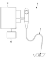
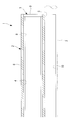
- FIG. 1 is an overall view showing an optical system for blood vessels according to an embodiment of the present invention. It is a longitudinal cross-sectional view which shows the optical apparatus for blood vessels which concerns on one Embodiment of this invention.
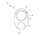
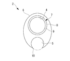
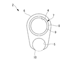
- FIG. 3 is a transverse sectional view showing the blood vessel optical device of FIG. 2. It is a cross-sectional view showing the optical system for blood vessels of FIG. It is a cross-sectional view showing a first modification of the optical device for blood vessels of FIG. It is a cross-sectional view showing a second modification of the blood vessel optical device of FIG. It is a cross-sectional view showing a third modification of the optical device for blood vessels of FIG. It is a cross-sectional view showing a fourth modification of the optical device for blood vessels of FIG.
- a blood vessel optical system 1 includes a blood vessel optical device 2 according to the present embodiment, a guide wire (long member) 3 having a circular cross section, and a blood vessel.
- the control apparatus 50 which controls the optical apparatus 2 for operation, and the monitor 60 are provided.
- the blood vessel optical system 1 is an optical system that scans illumination light along a spiral scanning locus on a (subject) X in a blood vessel and acquires an image of a lesion X.
- the optical device 2 for blood vessels is a long tubular shape including a lumen 4 and a dovetail groove 5 that are made of a flexible material and penetrate in the longitudinal direction.
- the optical member 7 includes a light detection unit 8 including a plurality of optical fibers (optical fiber bundles) arranged in the circumferential direction of a tube having a circular cross section, and is disposed inside the light detection unit 8, for example, not shown.
- an illumination unit 9 including an optical fiber scanner.
- the sheath 6 is made of, for example, a resin containing an X-ray contrast material. As shown in FIG. 3, the sheath 6 has a substantially oval cross-sectional shape having a short diameter and a long diameter, and is provided with a lumen 4 and dovetail grooves 5 arranged along the long diameter direction. Yes.
- the lumen 4 provided in the sheath 6 has, for example, a circular cross-sectional shape having an inner diameter that accommodates the optical member 7 having a circular cross-section.
- the dovetail groove 5 provided in the sheath 6 has an opening 10 that opens with a predetermined opening width toward the outer side opposite to the lumen 4, and has a groove width wider than the opening width of the opening 10 on the inner side.
- the dovetail groove 5 has an inner surface with a circular cross section, and an opening 10 that opens the inside of the dovetail groove 5 to the outside is provided at a position where the inner surface and the outer surface of the sheath 6 intersect.
- the diameter D is set slightly larger than the outer diameter of the guide wire 3.
- the guide wire 3 is accommodated in the dovetail groove 5 so as to be movable in the longitudinal direction.
- the cross-sectional shape of the sheath 6 is set so that the width dimension A in the minor axis direction is smaller than the width dimension C in the major axis direction.
- the minimum required wall thickness a is secured between the outer surface of the sheath 6 and the lumen 4 and between the lumen 4 and the dovetail groove 5. A broken line shown in FIG.
- the blood vessel optical system 1 and the blood vessel optical device 2 configured as described above will be described below.
- a guide made of an X-ray opaque material under X-ray observation using an X-ray observation apparatus In order to observe the lesion X in the blood vessel using the blood vessel optical system 1 according to the present embodiment, a guide made of an X-ray opaque material under X-ray observation using an X-ray observation apparatus.
- the wire 3 is inserted into the blood vessel and introduced to the lesion X.
- the proximal end of the guide wire 3 is inserted into the dovetail groove 5 from the distal end of the sheath 6, and the sheath 6 containing the optical member 7 in the lumen 4 is guided while guiding the guide wire 3. It is inserted into the blood vessel, and the tip of the sheath 6 is placed near the lesioned part X.
- the guide wire 3 inserted into the dovetail groove 5 is accommodated in a state in which a part in the circumferential direction protrudes from the opening 10 of the dovetail groove 5. Therefore, the guide wire 3 can smoothly guide the sheath 6 to the lesioned part X without dropping outside from the opening 10 of the dovetail groove 5.
- a virtual sheath (a lumen 4 ′ formed by closing the opening 10 of the dovetail groove 5 with the minimum necessary thickness a is shown by a broken line in FIG. 4 is provided. 3), the guide wire 3 is inserted into the dovetail groove 5, so that the minimum required thickness a of the sheath 6 is not required on the outside of the guide wire 3.
- the width dimension C can be reduced.
- the overall diameter can be reduced by making the width dimension A in the minor axis direction smaller than the width dimension C in the major axis direction.
- the sheath 6 is made of a material containing an X-ray contrast medium, the distal end position of the sheath 6 can be clearly identified under X-ray observation, and the lesion X It can be accurately placed in the vicinity. In this state, after the inside of the blood vessel is flushed, observation inside the blood vessel by the optical member 7 is started.
- the dovetail groove 5 that guides the guide wire 3 is adopted, and the short diameter direction is smaller than the width dimension C in the long diameter direction. Since the width dimension A is set small, there is an advantage that it is possible to easily introduce the sheath 6 into a thinner blood vessel while keeping the cross-sectional shape small. In addition, a space can be secured outside the sheath 6 as much as the cross-sectional shape is kept small, and another treatment tool or a fluid introduction path for flushing can be secured using the space. There are also advantages.
- the cross-sectional shape of the sheath 6 has been described as an oval shape. However, instead of this, as shown in FIG. As described above, an asymmetric shape in the major axis direction may be employed in accordance with the outer diameter of the optical member 7 and the outer diameter of the guide wire 3.
- the cross-sectional shape of the dovetail groove 5 has been described as a circle, instead of this, as long as it is an inner surface shape inscribed in the outer surface of the guide wire 3, as shown in FIG. It may be a shape having a groove width that gradually widens.
- the shape near the bottom surface of the dovetail groove 5 may have a groove width substantially equal to the diameter dimension of the guide wire 3.
- a dovetail groove 5 having a polygonal cross section circumscribing the cross section of the guide wire 3 may be employed.
- ridge lines are formed along the longitudinal direction of the sheath 6 on both sides of the opening 10 at the boundary where the inner surface of the dovetail groove 5 and the outer surface of the sheath 6 intersect.
- the ridge line becomes thin and sharp.
- the R processing may be performed at the time of molding the sheath 6 or may be performed after the molding.
- the optical member 7 is exemplified as having the optical detection unit 8 including a plurality of optical fibers arranged in the circumferential direction around the illumination unit 9 including the optical fiber scanner.
- an illumination unit 9 in which optical fibers for illumination are arranged in the accommodation light may be disposed around the light detection unit 8. Further, only the illumination unit 9 or only the light detection unit 8 may be inserted into the lumen 4.
- the guide wire 3 is illustrated as an elongate member. However, after the sheath 6 is introduced into the blood vessel using the guide wire 3 as a guide, the guide wire 3 is removed from the dovetail groove 5, and then the dovetail groove 5 is used as a guide for the other members. You may decide to introduce a treatment tool.
- the sheath 6 is exemplified by arranging the light detection unit 8 and the illumination unit 9 in the single lumen 4, but instead of this, as shown in FIG. Two lumens 4 may be provided in 6, and the light detection unit 8 and the illumination unit 9 may be separately disposed in each lumen 4.
- the sheath 6 has a substantially elliptical cross section satisfying the relationship of H ⁇ Z, where Z is the radius of the width dimension in the major axis direction of the sheath 6 and H is the radius of the width dimension in the minor axis direction of the sheath 6. It has a shape.
Landscapes
- Health & Medical Sciences (AREA)
- Life Sciences & Earth Sciences (AREA)
- Surgery (AREA)
- Medical Informatics (AREA)
- Engineering & Computer Science (AREA)
- Biomedical Technology (AREA)
- Biophysics (AREA)
- Radiology & Medical Imaging (AREA)
- Optics & Photonics (AREA)
- Nuclear Medicine, Radiotherapy & Molecular Imaging (AREA)
- Physics & Mathematics (AREA)
- Heart & Thoracic Surgery (AREA)
- Pathology (AREA)
- Molecular Biology (AREA)
- Animal Behavior & Ethology (AREA)
- General Health & Medical Sciences (AREA)
- Public Health (AREA)
- Veterinary Medicine (AREA)
- High Energy & Nuclear Physics (AREA)
- Endoscopes (AREA)
Abstract
ガイドワイヤによって案内しながらより細い血管内への導入を容易にすることを目的として、本発明に係る血管用光学装置(2)は、長手方向に貫通するルーメン(4)と、ルーメン(4)に並列して長手方向に沿って設けられたアリ溝(5)とを備える長尺のシース(6)と、ルーメン(4)内に収容され、体外から血管内の被写体に照明光を導く照明部(8)または被写体からの戻り光を体外に導く光検出部(9)の少なくとも一方からなる光学部材(7)とを備え、アリ溝(5)が、横断面円形の長尺部材(3)を長手方向に移動可能に収容可能な横断面形状を有するとともに、ルーメン(4)とは反対側に、収容した長尺部材(3)の周方向の一部を外部に突出させる長尺部材(3)の直径より小さい幅寸法の開口部(10)を有し、シース(6)が、ルーメン(4)とアリ溝(5)との配列方向より、配列方向に直交する方向に小さい外形寸法を有する。
Description
本発明は、血管用光学装置および血管用光学システムに関するものである。
血管内の病変部を観察するための血管用光学システムが知られている(例えば、特許文献1参照。)。
この血管用光学システムは、血管からの戻り光を伝播する光ファイバを貫通させるためのルーメンと、ガイドワイヤを貫通させるためのルーメンを備える管状シースを備えている。
この血管用光学システムは、血管からの戻り光を伝播する光ファイバを貫通させるためのルーメンと、ガイドワイヤを貫通させるためのルーメンを備える管状シースを備えている。
しかしながら、特許文献1の血管用光学システムでは、管状シースの先端部がガイドワイヤ用のルーメンを備えるために大径化しており、細い血管内への導入が困難であるという不都合がある。
本発明は上述した事情に鑑みてなされたものであって、ガイドワイヤによって案内しながらより細い血管内への導入を容易にすることができる血管用光学装置および血管用光学システムを提供することを目的としている。
本発明の一態様は、長手方向に貫通するルーメンと、該ルーメンに並列して前記長手方向に沿って設けられたアリ溝とを備える長尺のシースと、該シースの前記ルーメン内に収容され、体外から血管内の被写体に照明光を導く照明部または前記被写体からの戻り光を体外に導く光検出部の少なくとも一方からなる光学部材とを備え、前記アリ溝が、横断面円形の長尺部材を前記長手方向に移動可能に収容可能な横断面形状を有するとともに、前記ルーメンとは反対側に、収容した前記長尺部材の周方向の一部を外部に突出させる該長尺部材の直径より小さい幅寸法の開口部を有し、前記シースが、前記ルーメンと前記アリ溝との配列方向の外形寸法より、前記配列方向に直交する方向の外形寸法が小さい血管用光学装置である。
ルーメン内に光学部材を収容し、アリ溝内に横断面円形の長尺部材を収容すると、長尺部材の周方向の一部がアリ溝の開口部から外部に突出した状態に配置される。アリ溝の開口部が長尺部材の直径より小さい幅寸法で開口しているので、アリ溝内に収容された長尺部材が開口部から外側に脱落することなく収容状態に維持される。長尺部材を長手方向に移動可能に収容する部分をルーメンではなくアリ溝により構成したことで、開口部の位置におけるシースの肉厚を確保せずに済み、ルーメンとアリ溝との配列方向の外形寸法を小さく抑えることができる。さらに、ルーメンとアリ溝との配列方向の外形寸法よりそれに直交する方向の外形寸法を小さくすることにより、シースの細径化を図ることができる。すなわち、長尺部材として横断面円形のガイドワイヤを使用すれば、ガイドワイヤによって案内しながらより細い血管内への導入を容易にすることができる。
上記態様においては、前記シースの外面と、前記アリ溝の内面との境界の稜線にR加工が施されていてもよい。
このようにすることで、シースの外形を極力抑えてシースの外面とアリ溝の内面との境界の稜線が薄く形成されてもR加工によって稜線の先鋭化が防止され、血管内壁を傷つけないようにすることができる。
このようにすることで、シースの外形を極力抑えてシースの外面とアリ溝の内面との境界の稜線が薄く形成されてもR加工によって稜線の先鋭化が防止され、血管内壁を傷つけないようにすることができる。
また、上記態様においては、前記シースが、X線用造影材を含有する素材により構成されていてもよい。
このようにすることで、X線観察下で、血管内に挿入された血管用光学装置を鮮明に識別することができ、血管内での挿入作業を容易にすることができる。
このようにすることで、X線観察下で、血管内に挿入された血管用光学装置を鮮明に識別することができ、血管内での挿入作業を容易にすることができる。
また、上記態様においては、前記光学部材が、光ファイバスキャナを備える前記照明部であってもよい。
このようにすることで、血管内に導入された状態で、体外から導光した照明光を血管内の被写体に照射することができる。
このようにすることで、血管内に導入された状態で、体外から導光した照明光を血管内の被写体に照射することができる。
また、上記態様においては、前記光学部材が、光ファイバ束からなる前記光検出部であってもよい。
このようにすることで、血管内に導入された状態で、被写体から戻る戻り光を体外まで導光して検出することができる。
このようにすることで、血管内に導入された状態で、被写体から戻る戻り光を体外まで導光して検出することができる。
また、本発明の他の態様は、上記いずれかの血管用光学装置と、該血管用光学装置の前記アリ溝に前記長手方向に移動可能に挿入される前記長尺部材とを備える血管用光学システムである。
上記態様においては、前記長尺部材が、ガイドワイヤであってもよい。
上記態様においては、前記長尺部材が、ガイドワイヤであってもよい。
本発明によれば、ガイドワイヤによって案内しながらより細い血管内への導入を容易にすることができるという効果を奏する。
本発明の一実施形態に係る血管用光学装置2および血管用光学システム1について図面を参照して以下に説明する。
本実施形態に係る血管用光学システム1は、図1および図2に示されるように、本実施形態に係る血管用光学装置2と、横断面円形のガイドワイヤ(長尺部材)3と、血管用光学装置2を制御する制御装置50と、モニタ60とを備えている。
血管用光学システム1は、照明光を血管内の(被写体)X上でスパイラル状の走査軌跡に沿って走査し、病変部Xの画像を取得する光学システムである。
本実施形態に係る血管用光学システム1は、図1および図2に示されるように、本実施形態に係る血管用光学装置2と、横断面円形のガイドワイヤ(長尺部材)3と、血管用光学装置2を制御する制御装置50と、モニタ60とを備えている。
血管用光学システム1は、照明光を血管内の(被写体)X上でスパイラル状の走査軌跡に沿って走査し、病変部Xの画像を取得する光学システムである。
本実施形態に係る血管用光学装置2は、図2および図3に示されるように、可撓性を有する材料からなり長手方向に貫通するルーメン4とアリ溝5とを備える長尺のチューブ状のシース6と、該シース6のルーメン4内に収容された光学部材7とを備えている。
光学部材7は、横断面円形のチューブの周方向に配列された複数の光ファイバ(光ファイバ束)を備える光検出部8と、該光検出部8の内側に配置された、例えば、図示しない光ファイバスキャナを備える照明部9とを備えている。
光学部材7は、横断面円形のチューブの周方向に配列された複数の光ファイバ(光ファイバ束)を備える光検出部8と、該光検出部8の内側に配置された、例えば、図示しない光ファイバスキャナを備える照明部9とを備えている。
シース6は、例えば、X線用造影材を含有する樹脂により構成されている。
シース6は、図3に示されるように、短径と長径とを有する略長円形状の横断面形状を有するとともに、長径方向に沿ってルーメン4とアリ溝5とが配列して設けられている。シース6に設けられたルーメン4は、例えば、横断面円形の光学部材7を収容する内径寸法を有する円形の横断面形状を有している。
シース6は、図3に示されるように、短径と長径とを有する略長円形状の横断面形状を有するとともに、長径方向に沿ってルーメン4とアリ溝5とが配列して設けられている。シース6に設けられたルーメン4は、例えば、横断面円形の光学部材7を収容する内径寸法を有する円形の横断面形状を有している。
シース6に設けられたアリ溝5は、ルーメン4とは反対側の外側に向かって、所定の開口幅で開口する開口部10を有し、開口部10の開口幅より広い溝幅を内側に有している。
さらに詳細には、アリ溝5は横断面円形の内面を有し、該内面とシース6の外面とが交差する位置にアリ溝5の内部を外部に開放する開口部10が設けられている。
さらに詳細には、アリ溝5は横断面円形の内面を有し、該内面とシース6の外面とが交差する位置にアリ溝5の内部を外部に開放する開口部10が設けられている。
ここで、図4に示されるように、アリ溝5の横断面形状である円の直径をD、開口部10の開口幅をBとすると、
B<D
である。
B<D
である。
直径Dはガイドワイヤ3の外径より若干大きく設定されている。これにより、ガイドワイヤ3はアリ溝5内に長手方向に移動可能に収容されるようになっている。
また、本実施形態においては、長径方向の幅寸法Cよりも短径方向の幅寸法Aが小さくなるように、シース6の横断面形状が設定されている。さらに、本実施形態においては、シース6の外面とルーメン4との間、および、ルーメン4とアリ溝5との間に、最小必要肉厚aが確保されている。図4中に示される破線は、長径方向におけるシース6の外面から開口部10から露出するガイドワイヤ3の外面までの寸法に最小必要肉厚aの寸法を加えた直径寸法Eの仮想シースの円である。
また、本実施形態においては、長径方向の幅寸法Cよりも短径方向の幅寸法Aが小さくなるように、シース6の横断面形状が設定されている。さらに、本実施形態においては、シース6の外面とルーメン4との間、および、ルーメン4とアリ溝5との間に、最小必要肉厚aが確保されている。図4中に示される破線は、長径方向におけるシース6の外面から開口部10から露出するガイドワイヤ3の外面までの寸法に最小必要肉厚aの寸法を加えた直径寸法Eの仮想シースの円である。
このように構成された本実施形態に係る血管用光学システム1および血管用光学装置2の作用について以下に説明する。
本実施形態に係る血管用光学システム1を用いて、血管内部の病変部Xの観察を行うには、X線観察装置を使用したX線観察下において、X線不透過性の材質からなるガイドワイヤ3を血管内に挿入し、病変部Xまで導入する。
本実施形態に係る血管用光学システム1を用いて、血管内部の病変部Xの観察を行うには、X線観察装置を使用したX線観察下において、X線不透過性の材質からなるガイドワイヤ3を血管内に挿入し、病変部Xまで導入する。
ガイドワイヤ3が配置された後には、ガイドワイヤ3の基端をシース6の先端からアリ溝5内に挿入し、ガイドワイヤ3をガイドしながらルーメン4内に光学部材7を収納したシース6を血管内に挿入し、シース6の先端を病変部Xの近傍に配置する。
この場合において、アリ溝5内に挿入されたガイドワイヤ3はアリ溝5の開口部10から周方向の一部を突出させた状態で収容されるが、ガイドワイヤ3の外形寸法がアリ溝5の開口部10より大きいので、ガイドワイヤ3はアリ溝5の開口部10から外部に脱落することなく、シース6を病変部Xまで円滑にガイドすることができる。
この場合において、アリ溝5内に挿入されたガイドワイヤ3はアリ溝5の開口部10から周方向の一部を突出させた状態で収容されるが、ガイドワイヤ3の外形寸法がアリ溝5の開口部10より大きいので、ガイドワイヤ3はアリ溝5の開口部10から外部に脱落することなく、シース6を病変部Xまで円滑にガイドすることができる。
そして、この場合において、図4に破線で示される仮想シース(最小必要肉厚aによってアリ溝5の開口部10が閉じられて形成されたルーメン4’を有し、該ルーメン4’にガイドワイヤ3を挿入する構造のシース)と比較して、ガイドワイヤ3をアリ溝5に挿入することにより、ガイドワイヤ3の外側にシース6に最小必要肉厚aが不要となり、その分、長径方向の幅寸法Cを小さくすることができる。さらに、本実施形態においては、短径方向の幅寸法Aを長径方向の幅寸法Cより小さくすることで、全体にわたって細径化を図ることができる。これにより、より細い血管にも容易に導入することができるという利点がある。
また、本実施形態においては、シース6がX線用造影材を含有した材料により構成されているので、X線観察下においてシース6の先端位置を明確に識別することができ、病変部Xの近傍に正確に配置することができる。
この状態で、血管内をフラッシュしてから光学部材7による血管内の観察を開始する。
この状態で、血管内をフラッシュしてから光学部材7による血管内の観察を開始する。
このように本実施形態に係る血管用光学装置2および血管用光学システム1によれば、ガイドワイヤ3を案内するアリ溝5を採用し、かつ、長径方向の幅寸法Cよりも短径方向の幅寸法Aを小さく設定しているので、横断面形状を小さく抑えて、より細い血管へのシース6の導入を容易にすることができるという利点がある。また、横断面形状を小さく抑えた分だけ、シース6の外側にスペースを確保できて、そのスペースを利用して別の処置具、あるいは、フラッシュ用の流体の導入経路を確保することができるという利点もある。
なお、本実施形態においては、シース6の横断面形状を長円形状として説明したが、これに代えて、図5に示されるように、楕円形状に構成してもよいし、図6に示されるように、光学部材7の外径およびガイドワイヤ3の外径に合わせて長径方向に非対称な形状を採用してもよい。
また、アリ溝5の横断面形状を円形として説明したが、これに代えて、ガイドワイヤ3の外面に内接する内面形状であれば、図7に示されるように、開口部10から内部に向かって次第に広がる溝幅を有する形状であってもよい。あるいは、図8に示されるように、アリ溝5の底面近傍が、ガイドワイヤ3の直径寸法と略同等の溝幅を有する形状であってもよい。さらに、図9に示されるように、ガイドワイヤ3の横断面に外接する多角形状の横断面形状を有するアリ溝5を採用してもよい。
また、横断面において、アリ溝5の内面とシース6の外面とが交差する境界には、開口部10の両側に、シース6の長手方向に沿って稜線が形成されるが、アリ溝5の内面とシース6の外面との角度が近接すると稜線が薄く尖鋭になる。この場合には、図10に示されるように、稜線にエッジが形成されないようにR加工を施すことが好ましい。R加工は、シース6の成形時に施してもよいし、成形後に施してもよい。
また、本実施形態においては、光学部材7として、光ファイバスキャナを備える照明部9の周囲に周方向に配列された複数の光ファイバからなる光検出部8を備えるものを例示したが、これとは逆に、光検出部8の周囲に照明用の光ファイバを収容光に配列した照明部9を配置してもよい。
また、照明部9のみあるいは光検出部8のみをルーメン4に挿入してもよい。
また、照明部9のみあるいは光検出部8のみをルーメン4に挿入してもよい。
また、長尺部材としてガイドワイヤ3を例示したが、ガイドワイヤ3をガイドとしてシース6を血管内に導入した後に、ガイドワイヤ3をアリ溝5から抜き去り、その後アリ溝5をガイドとして他の処置具を導入することにしてもよい。
また、本実施形態においては、シース6として、単一のルーメン4に光検出部8とおよび照明部9を配置するものを例示したが、これに代えて、図11に示されるように、シース6に2つのルーメン4が設けられ、各ルーメン4に光検出部8および照明部9を別個に配置してもよい。
この場合、シース6は、シース6の長径方向の幅寸法の半径をZ、シース6の短径方向の幅寸法の半径をHとする、H<Zの関係を満足する略楕円形状の横断面形状を有している。
この場合、シース6は、シース6の長径方向の幅寸法の半径をZ、シース6の短径方向の幅寸法の半径をHとする、H<Zの関係を満足する略楕円形状の横断面形状を有している。
1 血管用光学システム
2 血管用光学装置
3 ガイドワイヤ(長尺部材)
4 ルーメン
5 アリ溝
6 シース
7 光学部材
8 光検出部
9 照明部
10 開口部
X 病変部(被写体)
2 血管用光学装置
3 ガイドワイヤ(長尺部材)
4 ルーメン
5 アリ溝
6 シース
7 光学部材
8 光検出部
9 照明部
10 開口部
X 病変部(被写体)
Claims (7)
- 長手方向に貫通するルーメンと、該ルーメンに並列して前記長手方向に沿って設けられたアリ溝とを備える長尺のシースと、
該シースの前記ルーメン内に収容され、体外から血管内の被写体に照明光を導く照明部または前記被写体からの戻り光を体外に導く光検出部の少なくとも一方からなる光学部材とを備え、
前記アリ溝が、横断面円形の長尺部材を前記長手方向に移動可能に収容可能な横断面形状を有するとともに、前記ルーメンとは反対側に、収容した前記長尺部材の周方向の一部を外部に突出させる該長尺部材の直径より小さい幅寸法の開口部を有し、
前記シースが、前記ルーメンと前記アリ溝との配列方向の外形寸法より、前記配列方向に直交する方向の外形寸法が小さい血管用光学装置。 - 前記シースの外面と、前記アリ溝の内面との境界の稜線にR加工が施されている請求項1に記載の血管用光学装置。
- 前記シースが、X線用造影材を含有する素材により構成されている請求項1または請求項2に記載の血管用光学装置。
- 前記光学部材が、光ファイバスキャナを備える前記照明部である請求項1から請求項3のいずれかに記載の血管用光学装置。
- 前記光学部材が、光ファイバ束からなる前記光検出部である請求項1から請求項4のいずれかに記載の血管用光学装置。
- 請求項1から請求項5のいずれかに記載の血管用光学装置と、
該血管用光学装置の前記アリ溝に前記長手方向に移動可能に挿入される前記長尺部材とを備える血管用光学システム。 - 前記長尺部材が、ガイドワイヤである請求項6に記載の血管用光学システム。
Priority Applications (3)
| Application Number | Priority Date | Filing Date | Title |
|---|---|---|---|
| PCT/JP2017/011028 WO2018167968A1 (ja) | 2017-03-17 | 2017-03-17 | 血管用光学装置および血管用光学システム |
| JP2019505665A JPWO2018167968A1 (ja) | 2017-03-17 | 2017-03-17 | 血管用光学装置および血管用光学システム |
| US16/563,062 US20190387966A1 (en) | 2017-03-17 | 2019-09-06 | Blood-vessel optical device and blood-vessel optical system |
Applications Claiming Priority (1)
| Application Number | Priority Date | Filing Date | Title |
|---|---|---|---|
| PCT/JP2017/011028 WO2018167968A1 (ja) | 2017-03-17 | 2017-03-17 | 血管用光学装置および血管用光学システム |
Related Child Applications (1)
| Application Number | Title | Priority Date | Filing Date |
|---|---|---|---|
| US16/563,062 Continuation US20190387966A1 (en) | 2017-03-17 | 2019-09-06 | Blood-vessel optical device and blood-vessel optical system |
Publications (1)
| Publication Number | Publication Date |
|---|---|
| WO2018167968A1 true WO2018167968A1 (ja) | 2018-09-20 |
Family
ID=63523558
Family Applications (1)
| Application Number | Title | Priority Date | Filing Date |
|---|---|---|---|
| PCT/JP2017/011028 Ceased WO2018167968A1 (ja) | 2017-03-17 | 2017-03-17 | 血管用光学装置および血管用光学システム |
Country Status (3)
| Country | Link |
|---|---|
| US (1) | US20190387966A1 (ja) |
| JP (1) | JPWO2018167968A1 (ja) |
| WO (1) | WO2018167968A1 (ja) |
Families Citing this family (1)
| Publication number | Priority date | Publication date | Assignee | Title |
|---|---|---|---|---|
| US11659981B2 (en) * | 2018-07-13 | 2023-05-30 | i-PRO Co., Ltd. | Endoscope with a holder including a lens and an image sensor |
Citations (3)
| Publication number | Priority date | Publication date | Assignee | Title |
|---|---|---|---|---|
| JPH034830A (ja) * | 1989-05-31 | 1991-01-10 | Olympus Optical Co Ltd | 内視鏡 |
| WO2015015887A1 (ja) * | 2013-07-31 | 2015-02-05 | オリンパスメディカルシステムズ株式会社 | カテーテル |
| WO2016167020A1 (ja) * | 2015-04-15 | 2016-10-20 | オリンパス株式会社 | 内視鏡用処置具および内視鏡用処置具の製造方法 |
-
2017
- 2017-03-17 JP JP2019505665A patent/JPWO2018167968A1/ja active Pending
- 2017-03-17 WO PCT/JP2017/011028 patent/WO2018167968A1/ja not_active Ceased
-
2019
- 2019-09-06 US US16/563,062 patent/US20190387966A1/en not_active Abandoned
Patent Citations (3)
| Publication number | Priority date | Publication date | Assignee | Title |
|---|---|---|---|---|
| JPH034830A (ja) * | 1989-05-31 | 1991-01-10 | Olympus Optical Co Ltd | 内視鏡 |
| WO2015015887A1 (ja) * | 2013-07-31 | 2015-02-05 | オリンパスメディカルシステムズ株式会社 | カテーテル |
| WO2016167020A1 (ja) * | 2015-04-15 | 2016-10-20 | オリンパス株式会社 | 内視鏡用処置具および内視鏡用処置具の製造方法 |
Also Published As
| Publication number | Publication date |
|---|---|
| US20190387966A1 (en) | 2019-12-26 |
| JPWO2018167968A1 (ja) | 2020-01-16 |
Similar Documents
| Publication | Publication Date | Title |
|---|---|---|
| CN105916428B (zh) | 具备立起台的内窥镜 | |
| US10368722B2 (en) | Endoscopic instrument and endoscopic instrument system | |
| US20120203066A1 (en) | Endoscope, guide unit, guide wire, medical-device guiding system, and medical-device guiding method | |
| JP5933872B1 (ja) | 内視鏡 | |
| EP2896352A1 (en) | Endoscope | |
| CN106231983B (zh) | 处置器具用适配器、内窥镜以及内窥镜系统 | |
| US20110098528A1 (en) | Fibers and tips thereof used with devices | |
| US20090292278A1 (en) | Multi-Stage Procedures with a Modifiable Fiber and a Guide Tube Containing an Instrument | |
| JP7566842B2 (ja) | 内視鏡装置 | |
| JP4481098B2 (ja) | 生体観察装置 | |
| WO2015147158A1 (ja) | 内視鏡用外科手術装置、処置具、及びガイド部材 | |
| JPWO2014157479A1 (ja) | 内視鏡下外科手術装置 | |
| US9993138B2 (en) | Rigid endoscope set | |
| US9649017B2 (en) | Endoscope | |
| JP2016150103A (ja) | 内視鏡 | |
| WO2016152192A1 (ja) | 生検システムおよび処置具 | |
| CN105208910B (zh) | 医疗器具 | |
| EP3335618A2 (en) | Imaging mini-scope for endoscope system | |
| WO2018167968A1 (ja) | 血管用光学装置および血管用光学システム | |
| WO2017195328A1 (ja) | 医療用オーバーチューブ | |
| JP2009261521A (ja) | 内視鏡用ガイドワイヤプローブ、ガイドワイヤプローブセット、及び超音波内視鏡 | |
| EP3400892A1 (en) | Surgical system and endoscope | |
| KR101451975B1 (ko) | 레이저 조사 장치와 레이저 조사 방법 | |
| JP5331424B2 (ja) | 内視鏡 | |
| KR102605924B1 (ko) | 병변 위치 판단 방법 및 이를 위한 내시경 시스템 |
Legal Events
| Date | Code | Title | Description |
|---|---|---|---|
| 121 | Ep: the epo has been informed by wipo that ep was designated in this application |
Ref document number: 17900672 Country of ref document: EP Kind code of ref document: A1 |
|
| ENP | Entry into the national phase |
Ref document number: 2019505665 Country of ref document: JP Kind code of ref document: A |
|
| NENP | Non-entry into the national phase |
Ref country code: DE |
|
| 122 | Ep: pct application non-entry in european phase |
Ref document number: 17900672 Country of ref document: EP Kind code of ref document: A1 |