WO2018118012A1 - Control of proppant redistribution during fracturing - Google Patents
Control of proppant redistribution during fracturing Download PDFInfo
- Publication number
- WO2018118012A1 WO2018118012A1 PCT/US2016/067581 US2016067581W WO2018118012A1 WO 2018118012 A1 WO2018118012 A1 WO 2018118012A1 US 2016067581 W US2016067581 W US 2016067581W WO 2018118012 A1 WO2018118012 A1 WO 2018118012A1
- Authority
- WO
- WIPO (PCT)
- Prior art keywords
- proppant
- flow rate
- fracture
- fracturing fluid
- fluid
- Prior art date
- Legal status (The legal status is an assumption and is not a legal conclusion. Google has not performed a legal analysis and makes no representation as to the accuracy of the status listed.)
- Ceased
Links
Classifications
-
- E—FIXED CONSTRUCTIONS
- E21—EARTH OR ROCK DRILLING; MINING
- E21B—EARTH OR ROCK DRILLING; OBTAINING OIL, GAS, WATER, SOLUBLE OR MELTABLE MATERIALS OR A SLURRY OF MINERALS FROM WELLS
- E21B41/00—Equipment or details not covered by groups E21B15/00 - E21B40/00
-
- C—CHEMISTRY; METALLURGY
- C09—DYES; PAINTS; POLISHES; NATURAL RESINS; ADHESIVES; COMPOSITIONS NOT OTHERWISE PROVIDED FOR; APPLICATIONS OF MATERIALS NOT OTHERWISE PROVIDED FOR
- C09K—MATERIALS FOR MISCELLANEOUS APPLICATIONS, NOT PROVIDED FOR ELSEWHERE
- C09K8/00—Compositions for drilling of boreholes or wells; Compositions for treating boreholes or wells, e.g. for completion or for remedial operations
- C09K8/60—Compositions for stimulating production by acting on the underground formation
- C09K8/62—Compositions for forming crevices or fractures
-
- C—CHEMISTRY; METALLURGY
- C09—DYES; PAINTS; POLISHES; NATURAL RESINS; ADHESIVES; COMPOSITIONS NOT OTHERWISE PROVIDED FOR; APPLICATIONS OF MATERIALS NOT OTHERWISE PROVIDED FOR
- C09K—MATERIALS FOR MISCELLANEOUS APPLICATIONS, NOT PROVIDED FOR ELSEWHERE
- C09K8/00—Compositions for drilling of boreholes or wells; Compositions for treating boreholes or wells, e.g. for completion or for remedial operations
- C09K8/60—Compositions for stimulating production by acting on the underground formation
- C09K8/80—Compositions for reinforcing fractures, e.g. compositions of proppants used to keep the fractures open
-
- E—FIXED CONSTRUCTIONS
- E21—EARTH OR ROCK DRILLING; MINING
- E21B—EARTH OR ROCK DRILLING; OBTAINING OIL, GAS, WATER, SOLUBLE OR MELTABLE MATERIALS OR A SLURRY OF MINERALS FROM WELLS
- E21B43/00—Methods or apparatus for obtaining oil, gas, water, soluble or meltable materials or a slurry of minerals from wells
- E21B43/25—Methods for stimulating production
- E21B43/26—Methods for stimulating production by forming crevices or fractures
- E21B43/267—Methods for stimulating production by forming crevices or fractures reinforcing fractures by propping
-
- E—FIXED CONSTRUCTIONS
- E21—EARTH OR ROCK DRILLING; MINING
- E21D—SHAFTS; TUNNELS; GALLERIES; LARGE UNDERGROUND CHAMBERS
- E21D11/00—Lining tunnels, galleries or other underground cavities, e.g. large underground chambers; Linings therefor; Making such linings in situ, e.g. by assembling
- E21D11/14—Lining predominantly with metal
- E21D11/36—Linings or supports specially shaped for tunnels or galleries of irregular cross-section
-
- G—PHYSICS
- G01—MEASURING; TESTING
- G01V—GEOPHYSICS; GRAVITATIONAL MEASUREMENTS; DETECTING MASSES OR OBJECTS; TAGS
- G01V20/00—Geomodelling in general
Definitions
- Fracturing treatments are commonly used in subterranean operations, among other purposes, to stimulate the production of desired fluids (e.g., oil, gas, water, etc.) from a subteiTanean formation.
- hydraulic fracturing treatments generally involve pumping a treatment fluid (e.g., a fracturing fluid) into a well bore that penetrates a subterranean formation at a sufficient hydraulic pressure to create or enhance one or more fractures in the subterranean formation.
- the creation and/or enhancement of these fractures may enhance the production of fluids from the subterranean formation.
- proppant may be deposited in the fracture, for example, by introducing a high viscosity fracturing fluid carrying those proppant into the subterranean formation.
- the proppant may prevent the fractures from fully closing upon the release of hydraulic pressure, forming conductive channels through which fluids may flow to the wellbore.
- Flow models have been used to simulate fluid flow in hydraulic fracturing treatments and other environments. Flow models may be used to simulate the flow of the proppant, for example, within a fracture network.
- FIG. 1 is a schematic view of an example simulated well system utilized for hydraulic fracturing.
- FIG. 2 is a schematic view of an example of a simulated wellbore after introduction of fracturing fluid.
- FIG. 3 illustrates an example of a proppant force analysis.
- FIG. 4 illustrates the dependence R(A) calculated for various values of a Stokes number.
- FIG. 5 illustrates an example algorithm utilizing a computer system.
- FIG. 6 illustrates an example computer system.
- the present disclosure may relate to subterranean operations, and, in one or more implementations, to fluid flow models utilized to analyze fluid flow during subterranean operations, such as, for example, hydraulic fracturing. More specifically, the present disclosure may relate to systems and methods for predicting particle flow rates to individual fractures based on pre-calculated dependencies of proppant collection efficiency on dimensionless parameters describing a local flow around an individual perforated exit from a wellbore.
- Proppant collection efficiency may be a parameter that measures a concentration difference between locations at a pipe inlet and inside a perforation. It may be defined as R in Equation (3), as shown below.
- perforations may have less proppant intake at the inlet; a large portion of proppant particles may not enter into the perforation.
- This scenario may be defined as low proppant collection efficiency.
- the maximum ratio of proppant flow rate to the perforation to flow rate of proppant in wellbore may be evaluated as the ratio of flow rate of the carrier fluid to the perforation to that in the wellbore.
- the proppant collection efficiency may be the ratio of the actual flow rate to the perforation to its maximum value. If proppant is "frozen" in the carrier fluid and moves along the fluid's streamlines, the collection efficiency may equal 1 .
- Perforations may connect the fractures to the wellbore. Because the flow conditions around each of the perforations may be different, the amount of proppant carried to each fracture may vary. The proppant inertia may also be taken into account for high flow rates and small diameters of the perforations, when the proppant does not follow the flow streamlines and the efficiency of proppant delivery to fractures decreases.
- the fluid (e.g., fracturing fluid) flow may be unsteady and multi-dimensional (e.g., three-dimensional or at least two-dimensional).
- a dominant flow may be two-dimensional and may include transient behaviors.
- two- or three-dimensional flow may be described by a one- dimensional flow model, for example, by integrating the governing flow equations over the cross-section of the two- or three-dimensional flow path.
- resulting equations may include nonlinear partial differential equations that may be solved using finite difference, finite volume, and/or finite element methods.
- the use of one-dimensional flow models may reduce computational costs, and may allow for faster or more computationally efficient simulations.
- a flow model may be used to perform numerical simulations in real time, for example, during a fracture treatment or during another well system activity.
- a fluid flow model may model a flow of fluid in a fracture, for example, during a hydraulic fracturing treatment or another type of injection treatment.
- a fluid flow model may model a flow and distribution of proppant in a fracture. Hydraulic fracturing treatment with proppant may improve the conductivity of a hydrocarbon reservoir, and modeling the hydraulic fracturing treatment, including proppant transport, may help to efficiently design, analyze, and/or optimize the treatment.
- a hydraulic fracturing model may combine simulations of fracture propagation, rock deformation, fluid flow, proppant transport, and other phenomena.
- the fluid flow models of the present disclosure may be utilized to account for complex physical conditions of the subterranean formation.
- proppant may play an important role by preventing the closure of fractures, and thus, may improve the production from a fracture- stimulated reservoir.
- the proppant may be delivered to individual fractures by a fracturing fluid, which may include an aqueous based fluid and/or additives (e.g., gelling agents) to increase viscosity of the fracturing fluid and reduce the particle sedimentation by gravity.
- a fracturing fluid which may include an aqueous based fluid and/or additives (e.g., gelling agents) to increase viscosity of the fracturing fluid and reduce the particle sedimentation by gravity.
- An aqueous based fluid may include fresh water or salt water.
- salt water is used herein to mean unsaturated salt solutions and saturated salt solutions including brines and seawater.
- salt may be added to the water to provide clay stability and to increase the density of the aqueous based fluid.
- salts include, but are not limited to, sodium chloride, sodium bromide, calcium chloride, potassium chloride, ammonium chloride and mixtures thereof.
- the salt or salts used can be present in the salt water in a concentration up to about 66% by weight thereof and the salt water can have a density up to about 15.5 pounds per gallon.
- the amount of water in the fracturing fluid may be up to about 80% to about 99.9%, depending on the concentration of salt and additives.
- Gelling agents may be included in the fracturing fluid to increase the fracturing fluid's viscosity which may be desired for a number of reasons in subterranean applications. For example, an increase in viscosity may be used for transferring hydraulic pressure to divert treatment fluids to another part of a formation or for preventing undesired leak-off of fluids into a formation from the buildup of filter cakes.
- the increased viscosity of the gelled or gelled and cross-linked treatment fluid may reduce fluid loss and may allow the fracturing fluid to transport significant quantities of suspended proppant particulates.
- Gelling agents may include, but are not limited to, any suitable crosslinkable polymer, including, but not limited to, galactomannan gums, cellulose derivatives, combinations thereof, derivatives thereof, and the like.
- Galactomannan gums are generally characterized as having a linear mannan backbone with various amounts of galactose units attached thereto.
- suitable galactomannan gums include, but are not limited to, gum arabic, gum ghatti, gum karaya, tamarind gum, tragacanth gum, guar gum, locust bean gum. combinations thereof, derivatives thereof, and the like.
- Suitable gums include, but are not limited to, hydroxyethylguar, hydroxypropylguar, carboxymethylguar, carboxymethylhydroxyethylguar and carboxymethylhydroxypropylguar.
- suitable cellulose derivatives include hydroxyethyl cellulose, carboxyethylcellulose, carboxyme hylcellulose, and carboxymethylhydroxyethylcellulose; derivatives thereof, and combinations thereof.
- the crosslinkable polymers included in the treatment fluids of the present disclosure may be naturally-occurring, synthetic, or a combination thereof.
- the crosslinkable polymers may comprise hydratable polymers that contain one or more functional groups such as hydroxy], cis-hydroxyl, carboxyl, sulfate, sulfonate, phosphate, phosphonate, amino, or amide groups.
- the crosslinkable polymers may be at least partially crosslinked, wherein at least a portion of the molecules of the crosslinkable polymers are crosslinked by a reaction comprising a crosslinking agent.
- the amount of gelling agent within the fracturing fluid may range from about 5 lbs/1 ,000 gal to about 60 lbs/1 ,000 gal.
- the amount of gelling agent may be up to 200 lbs/1 ,000 gal; however, if a low molecular weight material is used, the amount of gelling agent may exceed 200 lbs/ 1 ,000 gal.
- the proppant may include a collection of solid particles that may be injected into the subterranean formation, such that the solid particles hold (or "prop") open the fractures generated during a hydraulic fracturing treatment.
- the proppant may include a variety of solid particles, including, but not limited to, sand, bauxite, ceramic materials, glass materials, polymer materials, polytetrafluoroethylene materials, nut shell pieces, cured resinous particulates comprising nut shell pieces, seed shell pieces, cured resinous particulates comprising seed shell pieces, fruit pit pieces, cured resinous particulates comprising fruit pit pieces, wood, composite particulates, and combinations thereof.
- Suitable composite particulates may comprise a binder and a filler material wherein suitable filler materials include silica, alumina, fumed carbon, carbon black, graphite, mica, titanium dioxide, meta- silicate, calcium silicate, kaolin, talc, zirconia, boron, fly ash, hollow glass microspheres, solid glass, and combinations thereof.
- suitable filler materials include silica, alumina, fumed carbon, carbon black, graphite, mica, titanium dioxide, meta- silicate, calcium silicate, kaolin, talc, zirconia, boron, fly ash, hollow glass microspheres, solid glass, and combinations thereof.
- the proppant may comprise graded sand.
- the proppant may have a particle size in a range from about 2 mesh to about 400 mesh, U.S. Sieve Series.
- the proppant may have a particle size of about 10 mesh to about 70 mesh with distribution ranges of 10-20 mesh, 20-40 mesh,
- the proppant may be carried by the fracturing fluid.
- the proppant may be present in the fracturing fluid in a concentration of about 0.1 pounds per gallon ("ppg") to about 1 0 ppg, about 0.2 ppg to about 6 ppg. These ranges encompass every number in between, for example.
- the concentration may range between about 0.5 ppg to about 4 ppg.
- a curable resin may be coated or otherwise disposed on the proppant. Inclusion of the curable resin on the proppant may fill the fractures, providing an in-situ mechanical screen that can hold the proppant in place while maintaining integrity of the well.
- Curable resins suitable for use with the proppant may include any resin that is capable of forming a hardened, consolidated mass.
- curable resins are commonly used in consolidation treatments, and some suitable curable resins may include, without limitation, two component epoxy based resins, novolak resins, polyepoxide resins, phenol-aldehyde resins, urea-aldehyde resins, urethane resins, phenolic resins, furan resins, furan/furfuryl alcohol resins, phenolic/latex resins, phenol formaldehyde resins, polyester resins and hybrids and copolymers thereof, polyurethane resins and hybrids and copolymers thereof, acrylate resins, and mixtures thereof.
- curable resins such as epoxy resins
- an internal catalyst or activator so that when pumped downhole, they may be cured using only time and temperature.
- suitable curable resins such as furan resins may generally require a time-delayed catalyst or an external catalyst to help activate the polymerization of the resins if the cure temperature is low (i.e., less than about 250°F.) but may cure under the effect of time and temperature if the formation temperature is above about 250°F, preferably above about 300°F.
- the amount of curable resin may be from about 0.5% to about 5% v/w with respect to the proppant.
- Selection of a suitable curable resin may be affected by the temperature of the subterranean formation to which the proppant may be introduced.
- a suitable curable resin may be affected by the temperature of the subterranean formation to which the proppant may be introduced.
- a bottom hole static temperature BHST
- two component epoxy based resins comprising a hardenable resin component and a hardening agent component may be preferred.
- a furan based resin may be preferred, for example.
- a phenolic based resin or a one component HT epoxy based resin may be suitable, for example.
- a phenol/phenol formaldehyde/furfuryl alcohol resin may also be suitable, for example.
- the fracturing fluid may comprise any number of additional additives, including, but not limited to, salts, acids, fluid loss control additives, gas, foamers, corrosion inhibitors, catalysts, friction reducers, antifoam agents, bridging agents, dispersants, flocculants, 3 ⁇ 4S scavengers, CO 2 scavengers, oxygen scavengers, lubricants, weighting agents and any combination thereof.
- additional additives including, but not limited to, salts, acids, fluid loss control additives, gas, foamers, corrosion inhibitors, catalysts, friction reducers, antifoam agents, bridging agents, dispersants, flocculants, 3 ⁇ 4S scavengers, CO 2 scavengers, oxygen scavengers, lubricants, weighting agents and any combination thereof.
- FIG. 1 illustrates an example of a simulated well system 104 (e.g., wellbore simulation utilizing a wellbore simulator) that may be used to introduce proppant 1 16 into fractures 100.
- the simulated well system 104 may include a fluid handling system 106, which may include fluid supply 108, mixing equipment 109, pumping equipment 1 10, and wellbore supply conduit 1 12.
- Pumping equipment 1 10 may be fluidly coupled with the fluid supply 108 and wellbore supply conduit 1 12 to communicate a fracturing fluid 1 17, which may comprise proppant 1 16 into wellbore 1 14.
- the fluid supply 108 and pumping equipment 1 10 may be above the surface 1 1 8 while the wellbore 1 14 is below the surface 1 1 8.
- the simulated well system 104 may also be used for the injection of a pad or pre-pad fluid into the subterranean formation at an injection rate at or above the fracture gradient to create at least one fracture 100 in subterranean formation 120.
- the simulated well system 104 may then inject the fracturing fluid 1 17 into subterranean formation 120 surrounding the wellbore 1 14.
- a wellbore 1 14 may include horizontal, vertical, slanted, curved, and other types of wellbore geometries and orientations, and the proppant 1 16 may generally be applied to subterranean formation 120 surrounding any portion of wellbore 1 14, including fractures 100.
- the wellbore 1 14 may include the casing 102 that may be cemented (or otherwise secured) to the wall of the wellbore 1 14 by cement sheath 122.
- Perforations 123 may allow communication between the wellbore 1 14 and the subterranean formation 120. As illustrated, perforations 123 may penetrate casing 102 and cement sheath 122 allowing communication between interior of casing 102 and fractures 100.
- a plug 124 which may be any type of plug for oilfield applications (e.g., bridge plug), may be disposed in wellbore 1 14 below the perforations 123.
- a perforated interval of interest 130 may be isolated with plug 124.
- a pad or pre-pad fluid may be injected into the subterranean formation 120 at an injection rate at or above the fracture gradient to create at least one fracture
- proppantl 16 may be mixed with an aqueous based fluid via mixing equipment 109, thereby forming a fracturing fluid 1 17, and then may be pumped via pumping equipment 1 10 from fluid supply 108 down the interior of casing 102 and into subterranean formation 120 at or above a fracture gradient of the subterranean formation 120.
- Pumping the fracturing fluid 1 17 at or above the fracture gradient of the subsurface formation 120 may create (or enhance) at least one fracture (e.g., fractures 100) extending from the perforations 123 into the subterranean formation 120.
- the fracturing fluid 1 17 may be pumped down production tubing, coiled tubing, or a combination of coiled tubing and annulus between the coiled tubing and the casing 102.
- At least a portion of the fracturing fluid 1 17 may enter the fractures 100 of subterranean formation 120 surrounding wellbore 1 14 by way of perforations 123.
- Perforations 123 may extend from the interior of casing 102, through cement sheath 122, and into subterranean formation 120.
- Proppant 1 16 in accordance with systems and/or methods of the present disclosure.
- Proppant 1 16 may be positioned within fractures 100, thereby propping open fractures 100.
- the pumping equipment 1 10 may include a high pressure pump.
- the term "high pressure pump” refers to a pump that is capable of delivering the fracturing fluid 1 17 and/or pad/pre-pad fluid downhole at a pressure of about 1000 psi or greater.
- a high pressure pump may be used when it is desired to introduce the fracturing fluid
- the high pressure pump may be capable of fluidly conveying particulate matter, such as the proppantl 16, into the subterranean formation 120.
- Suitable high pressure pumps may include, but are not limited to, floating piston pumps and positive displacement pumps.
- the initial pumping rates of the pad fluid, pre-pad fluid and/or fracturing fluid 1 17 may range from about 15 barrels per minute ("bbl/min") to about 80 bbl/min, enough to effectively create a fracture into the formation and place the proppantl 16 into at least one fracture 101.
- the pumping equipment 1 10 may include a low pressure pump.
- the term "low pressure pump” refers to a pump that operates at a pressure of about 1000 psi or less.
- a low pressure pump may be fluidly coupled to a high pressure pump that may be fluidly coupled to a tubular (e.g., wellbore supply conduit 1 12).
- the low pressure pump may be configured to convey the fracturing fluid 1 17 and/or pad/pre-pad fluid to the high pressure pump.
- the low pressure pump may "step up" the pressure of the fracturing fluid 1 17 and/or pad/pre-pad fluid before it reaches the high pressure pump.
- Mixing equipment 109 may include a mixing tank that is upstream of the pumping equipment 1 10 and in which the fracturing fluid 1 17 may be formulated.
- the pumping equipment 1 10 e.g., a low pressure pump, a high pressure pump, or a combination thereof
- the fracturing fluid 1 17 may be formulated offsite and transported to a worksite, in which case the fracturing fluid 1 17 may be introduced to the casing 102 via the pumping equipment 1 ] 0 directly from its shipping container (e.g., a truck, a railcar, a barge, or the like) or from a transport pipeline. In either case, the fracturing fluid 1 17 may be drawn into the pumping equipment 1 10, elevated to an appropriate pressure, and then introduced into the casing 102 for delivery downhole.
- its shipping container e.g., a truck, a railcar, a barge, or the like
- the exemplary fracturing fluid disclosed herein may directly or indirectly affect one or more components or pieces of equipment associated with the preparation, delivery, recapture, recycling, reuse, and/or disposal of the fracturing fluid.
- the fracturing fluid may directly or indirectly affect one or more mixers, related mixing equipment, mud pits, storage facilities or units, composition separators, heat exchangers, sensors, gauges, pumps, compressors, and the like used generate, store, monitor, regulate, and/or recondition the sealant composition.
- the fracturing fluid may also directly or indirectly affect any transport or delivery equipment used to convey the fracturing fluid to a well site or downhole such as, for example, any transport vessels, conduits, pipelines, trucks, tubulars, and/or pipes used to compositionally move the fracturing fluid from one location to another, any pumps, compressors, or motors (e.g., topside or downhole) used to drive the fracturing fluid into motion, any valves or related joints used to regulate the pressure or flow rate of the fracturing fluid, and any sensors (i.e., pressure and temperature), gauges, and/or combinations thereof, and the like.
- any transport or delivery equipment used to convey the fracturing fluid to a well site or downhole
- any transport vessels, conduits, pipelines, trucks, tubulars, and/or pipes used to compositionally move the fracturing fluid from one location to another
- any pumps, compressors, or motors e.g., topside or downhole
- any valves or related joints used to regulate the
- the disclosed fracturing fluid may also directly or indirectly affect the various downhole equipment and tools that may come into contact with the fracturing fluid such as, but not limited to, wellbore casing, wellbore liner, completion string, insert strings, drill string, coiled tubing, s!ickline, wireline, drill pipe, drill collars, mud motors, downhole motors and/or pumps, cement pumps, surface-mounted motors and/or pumps, centralizers, turbolizers, scratchers, floats (e.g., shoes, collars, valves, etc.), logging tools and related telemetry equipment, actuators (e.g., electromechanical devices, hydromechanical devices, etc.), sliding sleeves, production sleeves, plugs, screens, filters, flow control devices (e.g., inflow control devices, autonomous inflow control devices, outflow control devices, etc.), couplings (e.g., electro-hydraulic wet connect, dry connect, inductive coupler, etc.), control lines (e.g., electrical, fiber optic, hydraulic
- FIG. 3 illustrates an example of a proppant particle force analysis, which may include a section of wellbore 1 14 containing an outlet (e.g., perforation 123).
- the perforation 123 may be modeled as a circular pipe of a smaller diameter (e.g., 1 /10 or less of that of the wellbore 1 14).
- the fracturing fluid 1 17 and its flow into perforation 123 is represented on FIG. 3 by the illustrated streamlines.
- Proppant 1 16 e.g., shown on FIG. 1
- the proppant collection efficiency R of proppant diversion to fracture 100 may be defined as:
- the dimension analysis may yield the following dimensionless parameters which may define a local 2-phase flow, as shown in FIG. 3.
- a is the particle radius.
- p p and ⁇ are the particle and fluid density, respectively, ⁇ is the fluid viscosity, V t and V render- are the average fluid speed in the fracture 100 and wellbore 1 14, respectively, g is the gravity acceleration, D j - and D w are the diameters of fracture 100 and wellbore 1 14, respectively, Fr is the Froude number, Re is the Reynolds number and St is the Stokes number. It may be assumed that the fracture diameter is small enough (e.g., 1 /10 or less of that of the wellbore 1 14), so that the gravity effect on the particle motion near the junction is negligible.
- Equation 5 for the Stokes number may be generalized:
- the dependence of the proppant collection efficiency on the parameters St and ⁇ may be determined numerically by solving equations of particle and fluid motion with geometry of the fracture entrance area (e.g., perforation 123) as shown in FIG. 3.
- FIG. 4 illustrates the dependence R(A) calculated for various values of a Stokes number in a simulated example.
- Proppant collection efficiency R may be a function of the fracture-well bore fluid flow rate ratio ⁇ calculated for different values of Stokes number in the case of a Newtonian fluid.
- the fluid flow rate ratio is a ratio of a flow rate of the fracturing fluid in the fracture versus a flow rate in the well bore. As expected, the efficiency may be close to 1 at low values of St, but may decrease monotonously with increasing St.
- Calculations performed for a range of pipe diameters and flow velocities showed weak effects of fracture-wellbore diameter ratio ⁇ and Reynolds number on the proppant collection efficiency. These results may imply that the proppant collection efficiency R can be considered depending only on the Stokes number and ratio of velocities ⁇ , provided the proppant concentration is low enough (e.g., less than about 10% by volume).
- the algorithm may include calculating the fluid flow.
- Fluid flow may be calculated, for example, using a computer system, such as, for example, a wellbore simulator (e.g., single phase wellbore simulator).
- the calculated fluid flow may include the flow of the fracturing fluid (e.g., fracturing fluid 1 17 shown on FIGS. 1 and 2), including the fluid flow rate and flow ratio ⁇ ⁇ (Eq. l ) to the fracture of interest (e.g., fractures 100 shown on FIGS.
- the algorithm may include calculating dimensionless parameters.
- the dimensionless parameters may describe a local flow around an individual perforated exit (e.g., perforation 123) from wellbore 1 14.
- the dimensionless parameters may be calculated based on properties of proppant particles (e.g., proppant 1 16 shown on FIGS. 1 and 2) and fracturing fluid 1 17.
- the dimensionless parameters may be calculated with a computer system and may include the parameters ⁇ an Si for the fracture 100.
- the parameters ⁇ an Sf may be describe a local two phase flow and may be defined by Equation 5.
- the algorithm may include determining proppant collection efficiency R using pre-calculated data.
- the pre-calculated data may include pre-calculated tables or graphs similar to that in FIG. 4.
- a computer system may be used to determine the proppant collection efficiency R.
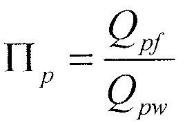
- the algorithm may include calculating the proppant mass flow rate to the fracture 100 based on Equations (2) and (3) as follows:
- Q pw is the total mass flow rate of proppant 1 16 through wellbore 1 14, as shown on FIGS. 1 and 2.
- This algorithm may allow an efficient calculation of the proppant flow rate to individual fractures and perforations based on pre-calculated and tabulated values of the collection efficiency and routine calculation of the liquid flow rates in the system, eliminating the need for corresponding 3D simulations of the proppant transport, which are too CPU- expensive.
- a proppant collection efficiency calculation may give a prediction about an amount of proppant that may be transported into the perforations. The proppant collection efficiency calculation may help to estimate if there is a sufficient amount of proppant or indicate an insufficient amount of proppant.
- Equations (1 ) - (7) e.g., mass flow rates of a fracturing fluid, proppant collection efficiency R, dimensionless parameters which may define a local 2-phase flow, particle mass flow rates, Stokes number, proppant mass flow rate, etc.
- proppant transport to fractures e.g., fractures 100
- estimating for example, an amount of proppant delivered to individual fractures.
- the present disclosure may be implemented through a computer-executable program of instructions, such as program modules, generally referred to as software applications or application programs executed by a computer.
- the software may include, for example, routines, programs, objects, components and data structures that perform particular tasks or implement particular abstract data types.
- the software may form an interface to allow a computer to react according to a source of input.
- the software may be stored and/or carried on any variety of memory such as CD-ROM, magnetic disk, bubble memory and semiconductor memory (e.g. , various types of RAM or ROM).
- the software and its results may be transmitted over a variety of carrier media such as optical fiber, metallic wire and/or through any of a variety of networks, such as the Internet.
- the present disclosure may be practiced with a variety of computer-system configurations, including hand-held devices, multiprocessor systems, microprocessor-based or programmable-consumer electronics, minicomputers, mainframe computers, and the like. Any number of computer-systems and computer networks are acceptable for use with the present disclosure.
- the present disclosure may be practiced in distributed-computing environments where tasks are performed by remote- processing devices that are linked through a communications network.
- program modules may be located in both local and remote computer- storage media including memory storage devices.
- the present disclosure may therefore, be implemented in connection with various hardware, software or a combination thereof, in a computer system or other processing system.
- each program and/or software may execute on its own computer system, such as a server computer system, with the interaction occurring by way of network (e.g., local area network (LAN), wide area network (WAN), across the Internet).
- network e.g., local area network (LAN), wide area network (WAN), across the Internet.
- LAN local area network
- WAN wide area network
- Internet Internet
- FIG. 6 illustrates a computer system 600 in accordance with at least some systems and/or methods of the present disclosure, and upon which at least some of the various systems and/or methods may be implemented. That is, some or all of the various systems and/or methods may execute on a computer system such as shown in FIG. 6, multiple computers systems such as shown in FIG. 6, and/or one or more computer systems equivalent to the FIG. 6, including after-developed computer systems.
- computer system 600 may comprise a main processor 610 coupled to a main memory 612, and various other peripheral computer system components, through integrated host bridge 614.
- the main processor 610 may be a single processor core device, or a processor implementing multiple processor cores.
- computer system 600 may implement multiple main processors 610.
- the main processor 610 may couple to the host bridge 614 by way of a host bus 616 or the host bridge 614 may be integrated into the main processor 610.
- the computer system 600 may implement other bus configurations or bus-bridges in addition to, or in place of, those shown in FIG. 6.
- the main memory 612 may couple to the host bridge 614 through a memory bus 618.
- the host bridge 614 may comprise a memory control unit that controls transactions to the main memory 612 by asserting control signals for memory accesses.
- the main processor 610 may directly implement a memory control unit, and the main memory 612 may couple directly to the main processor 610.
- the main memory 612 may function as the working memory for the main processor 610 and may comprise a memory device or array of memory devices in which programs, instructions and data may be stored.
- the main memory 612 may comprise any suitable type of memory such as dynamic random access memory (DRAM) or any of the various types of DRAM devices such as synchronous DRAM (SDRAM) (including double data rate (DDR) SDRAM, double- data-rate two (DDR2) SDRAM, double-data-rate three (DDR3) SDRAM), extended data output DRAM (EDODRAM), or Rambus DRAM (RDRAM).
- DRAM dynamic random access memory
- SDRAM synchronous DRAM
- DDR double data rate SDRAM
- DDR2 SDRAM double- data-rate two SDRAM
- DDR3 SDRAM double-data-rate three SDRAM
- EDODRAM extended data output DRAM
- RDRAM Rambus DRAM
- the main memory 612 may be an example of a non-transitory computer-readable medium storing programs and instructions, and other examples are disk drives and flash memory devices.
- the illustrative computer system 600 also may comprises a bridge device 628 that may bridge the primary expansion bus 626 to various secondary expansion buses, such as a low pin count (LPC) bus 630 and peripheral components interconnect (PCI) bus 632.
- Various other secondary expansion buses may be supported by the bridge device 628.
- the bridge device 628 may comprise an Input/Output Controller Hub (ICH), and thus the primary expansion bus 626 may comprise a hub-link bus.
- ICH Input/Output Controller Hub
- computer system 600 may not be limited to any particular chip set manufacturer, and thus bridge devices and expansion bus protocols from several manufacturers may be equivalently used.
- Firmware hub 636 may couple to the bridge device 628 by way of the LPC bus 630.
- the firmware hub 636 may comprise read-only memory (ROM) which may contain software programs executable by the main processor 610.
- the computer system 600 may further comprise a network interface card (N IC) 638 illustratively coupled to the PCI bus 632.
- the NIC 638 may act to couple the computer system 600 to a communication network, such as the Internet.
- computer system 600 may further comprise a super input/output (I/O) controller 640 that may be coupled to the bridge device 628 by way of the I/O controller 640
- the Super I/O controller 640 may control many computer system functions, for example interfacing with various input and output devices such as, for example, a keyboard 642, a pointing device 644 (e.g., mouse), various serial ports, floppy drives and hard disk drives (HD) 641.
- a keyboard 642 e.g., a keyboard 642
- a pointing device 644 e.g., mouse
- various serial ports e.g., floppy drives and hard disk drives (HD) 641.
- HD hard disk drives
- Inputs may be wellbore trajectory, diameter in each location, completion design, liquid properties, such as, for example, density and viscosity, proppant properties such as, for example, density and average diameter, liquid flow rate, proppant pumping rate, proppant volume fraction, wellbore pressure and temperature profiles, perforation design, etc.
- Proppant collection efficiency parameter may be calculated as an intermediate parameter that may not be shown in a user graphical interface of a software application. The final results may be shown as liquid and proppant mass flow distributions.
- the hard disk drives 641 may be another example of a computer-readable media.
- the hard disk drives 641 may couple to a separate drive controller coupled to a more powerful expansion bus, such as the PCI bus 632, particularly in cases where the hard disk drive is implemented as an array of drives (e.g., redundant array of independent (or inexpensive) disks (RAID)).
- the computer system 600 may be a server computer system, the keyboard 642, and pointing device 644 may be omitted.
- the computer system 600 may further comprise a graphics processing unit (GPU) 650 coupled to the host bridge 614 by way of bus 652, such as a PCI Express (PCI-E) bus or Advanced Graphics Processing (AGP) bus.
- PCI-E PCI Express
- AGP Advanced Graphics Processing
- the graphics processing unit 650 may alternatively couple to the primary expansion bus 626, or one of the secondary expansion buses (e.g., PCI bus 632).
- the graphics processing unit 650 may couple to a display system 654 which may comprise any suitable electronic display device or multiple distinct display devices, upon which any image or text may be displayed.
- the graphics processing unit 650 may comprise an onboard processor 656, as well as onboard memory 658.
- the processor 656 may thus perform graphics processing, as commanded by the main processor 610.
- the memory 658 may be significant, on the order of several hundred gigabytes or more.
- the graphics processing unit 650 may perform significant calculations regarding graphics to be displayed on the display system, and ultimately display such graphics, without further input or assistance of the main processor 610.
- the graphics processing unit 650 and display system 654 may be omitted.
- the systems and methods may include any of the various features of the systems and methods disclosed herein, including one or more of the following statements.
- a method may comprise calculating fluid flow with a computer system, wherein the fluid flow is a flow of a fracturing fluid comprising proppant; calculating dimensionless parameters with the computer system, wherein the dimensionless parameters comprise a description of a local flow around an individual perforated exit from a wellbore to a fracture; determining a proppant collection efficiency using pre-calculated data with the computer system; calculating a proppant flow rate to the fracture with the computer system; and calculating with the computer system , an amount of the proppant delivered to the fracture based on one or more of the dimensionless parameters, the proppant collection efficiency, or the proppant flow rate to the fracture.
- Statement 2 The method of Statement 1 , wherein the calculating a proppant flow rate comprises utilizing Q p f — ⁇ X ⁇ / X Q pw , wherein Q p j is a particle mass flow rate in the fracture; wherein Q, declaration, is a particle mass flow rate in the wellbore; wherein R is the proppant collection efficiency; wherein I7i is a ratio of a mass flow rate of the fracturing fluid in the wellbore to a mass flow rate of the fracturing fluid in the fracture.
- Statement 3 The method of Statement 1 or Statement 2, wherein the fracturing fluid further comprises a gelling agent.
- Statement 4 The method of any preceding statement, wherein flow of the proppant in the fluid flow has different trajectories than the flow of the fracturing fluid in the fluid flow.
- Statement 5 The method of any preceding statement, wherein the computer system is a single phase simulator.
- Statement 6 The method of any preceding statement, wherein the fracturing fluid comprises the proppant in an amount of about 10 vol.% or less based on the total volume of the fracturing fluid.
- Statement 7 The method of any preceding statement, further comprising displaying on a display device at least one of the proppant collection efficiency, the proppant flow rate, or the description of a local flow around an individual perforated exit from a wellbore.
- Statement 8 The method of any preceding statement, wherein the proppant collection efficiency is a function of a fluid flow rate ratio of a flow rate of the fracturing fluid in the wellbore versus a flow rate of the fracturing fluid in the fracture.
- Statement 9 The method of any preceding statement, wherein the proppant collection efficiency is calculated for different values of a Stokes number for Newtonian fluids.
- a system may comprise a processor; and a memory coupled to the processor, wherein the memory may store a program configured to: calculate a fluid flow, wherein the fluid flow is a flow of a fracturing fluid comprising proppant; calculate dimensionless parameters; determine a proppant collection efficiency utilizing pre-calculated data; calculate a proppant flow rate to the fracture; and calculate an amount of the proppant delivered to the fracture based on the fluid flow, the dimensionless parameters, the proppant collection efficiency, and the proppant flow rate to the fracture.
- Statement 1 1 The system of Statement 10, wherein the program is configured
- Statement 12 The system of Statement 10 or Statement 1 1 , wherein flow of the proppant has different trajectories than the flow of the fracturing fluid.
- Statement 13 The system of any one of Statements 10 to 12, wherein a concentration of the proppant is less than about 10% by volume of the fracturing fluid.
- Statement 14 The system of any one of Statements 10 to 13, wherein the proppant collection efficiency is a function of a fluid flow rate ratio of a flow rate of the fracturing fluid in the wellbore versus a flow rate of the fracturing fluid in the fracture.
- Statement 15 The system of any one of Statements 10 to 14, wherein the proppant collection efficiency is calculated for different values of a Stokes number for Newtonian fluids.
- Statement 16 The system of any one of Statements 10 to 15, wherein the dimensionless parameters comprise a description of a local flow around an individual perforated exit from a wellbore.
- Statement 17 A non-transitory computer-readable media storing a program, wherein the program may be configured to: calculate a fluid flow, wherein the fluid flow is a flow of a fracturing fluid comprising a proppant; calculate dimensionless parameters, wherein the dimensionless parameters comprise a description of a local flow around an individual perforated exit from a wellbore to a fracture; determine a proppant collection efficiency utilizing pre-calculated data; calculate a proppant flow rate to the fracture; and calculate an amount of the proppant delivered to the fracture based on the fluid flow, the dimensionless parameters, the proppant collection efficiency, and the proppant flow rate to the fracture.
- Statement 1 8 The non-transitory computer-readable media storing a program of Statement 17, wherein the program may be configured to calculate the proppant flow rate by utilizing Q p f — ⁇ / X Q pw , wherein Q p / is a particle mass flow rate in the fracture; wherein Q pil is a particle mass flow rate in a wellbore; wherein R is the proppant collection efficiency; wherein 77/ is a ratio of a mass flow rate of the fracturing fluid in the wellbore to a mass flow rate of the fracturing fluid in the fracture.
- Statement 19 The non-transitory computer-readable media storing a program of Statement 1 7 or Statement 18, wherein the proppant collection efficiency is a function of a fluid flow rate ratio of a flow rate of the fracturing fluid in the wellbore versus a flow rate of the fracturing fluid in the fracture.
- Statement 20 The non-transitory computer-readable media storing a program of any one of Statements 17 to 19, wherein the proppant collection efficiency is calculated for different values of a Stokes number for Newtonian fluids.
- the procedure may need to be repeated to yield proppant flow distribution in the whole fracture system (e.g., fractures 100 as shown on FIGS. 1 and 2).
- compositions and methods are described in terms of “comprising,” “containing,” or “including” various components or steps, the compositions and methods can also “consist essentially of or “consist of the various components and steps.
- indefinite articles “a” or “an,” as used in the claims, are defined herein to mean one or more than one of the element that it introduces.
- program and “software” may refer to executable computer code, groups of executable computer code, or computer code that may become or be used to create execute computer code.
- Particular components referred to as “programs” in the present disclosure may equivalently be referred to as “software”.
- particular components referred to as “software” in the present disclosure may equivalently be referred to as “programs”.
- the terminology may be adopted merely to help the reader distinguish different computer codes (or groups of computer code).
- ranges from any lower limit may be combined with any upper limit to recite a range not explicitly recited, as well as, ranges from any lower limit may be combined with any other lower limit to recite a range not explicitly recited, in the same way, ranges from any upper limit may be combined with any other upper limit to recite a range not explicitly recited.
- any numerical range with a lower limit and an upper limit is disclosed, any number and any included range falling within the range are specifically disclosed.
- every range of values (of the form, "from about a to about b,” or, equivalently, “from approximately a to b,” or, equivalently, “from approximately a-b") disclosed herein is to be understood to set forth every number and range encompassed within the broader range of values even if not explicitly recited.
- every point or individual value may serve as its own lower or upper limit combined with any other point or individual value or any other lower or upper limit, to recite a range not explicitly recited.
Landscapes
- Engineering & Computer Science (AREA)
- Life Sciences & Earth Sciences (AREA)
- Mining & Mineral Resources (AREA)
- Geology (AREA)
- General Life Sciences & Earth Sciences (AREA)
- Chemical & Material Sciences (AREA)
- Geochemistry & Mineralogy (AREA)
- Physics & Mathematics (AREA)
- Environmental & Geological Engineering (AREA)
- Fluid Mechanics (AREA)
- Materials Engineering (AREA)
- Organic Chemistry (AREA)
- Architecture (AREA)
- Civil Engineering (AREA)
- Structural Engineering (AREA)
- Geophysics (AREA)
- General Physics & Mathematics (AREA)
- Management, Administration, Business Operations System, And Electronic Commerce (AREA)
- Aerodynamic Tests, Hydrodynamic Tests, Wind Tunnels, And Water Tanks (AREA)
- Flow Control (AREA)
- Diaphragms For Electromechanical Transducers (AREA)
- Transition And Organic Metals Composition Catalysts For Addition Polymerization (AREA)
- Laminated Bodies (AREA)
- General Engineering & Computer Science (AREA)
- Operations Research (AREA)
Abstract
Description



Claims
Priority Applications (7)
| Application Number | Priority Date | Filing Date | Title |
|---|---|---|---|
| PCT/US2016/067581 WO2018118012A1 (en) | 2016-12-19 | 2016-12-19 | Control of proppant redistribution during fracturing |
| AU2016433048A AU2016433048A1 (en) | 2016-12-19 | 2016-12-19 | Control of proppant redistribution during fracturing |
| GB1905092.1A GB2569263A (en) | 2016-12-19 | 2016-12-19 | Control of proppant redistribution during fracturing |
| US16/348,399 US20200080403A1 (en) | 2016-12-19 | 2016-12-19 | Control of Proppant Redistribution During Fracturing |
| CA3040667A CA3040667A1 (en) | 2016-12-19 | 2016-12-19 | Control of proppant redistribution during fracturing |
| FR1760833A FR3060635A1 (en) | 2016-12-19 | 2017-11-17 | CONTROL OF REDISTRIBUTION OF SUPPORT AGENT DURING FRACTURATION |
| NO20190472A NO20190472A1 (en) | 2016-12-19 | 2019-04-08 | Control of proppant redistribution during fracturing |
Applications Claiming Priority (1)
| Application Number | Priority Date | Filing Date | Title |
|---|---|---|---|
| PCT/US2016/067581 WO2018118012A1 (en) | 2016-12-19 | 2016-12-19 | Control of proppant redistribution during fracturing |
Publications (1)
| Publication Number | Publication Date |
|---|---|
| WO2018118012A1 true WO2018118012A1 (en) | 2018-06-28 |
Family
ID=62510517
Family Applications (1)
| Application Number | Title | Priority Date | Filing Date |
|---|---|---|---|
| PCT/US2016/067581 Ceased WO2018118012A1 (en) | 2016-12-19 | 2016-12-19 | Control of proppant redistribution during fracturing |
Country Status (7)
| Country | Link |
|---|---|
| US (1) | US20200080403A1 (en) |
| AU (1) | AU2016433048A1 (en) |
| CA (1) | CA3040667A1 (en) |
| FR (1) | FR3060635A1 (en) |
| GB (1) | GB2569263A (en) |
| NO (1) | NO20190472A1 (en) |
| WO (1) | WO2018118012A1 (en) |
Cited By (1)
| Publication number | Priority date | Publication date | Assignee | Title |
|---|---|---|---|---|
| US11215034B2 (en) | 2017-04-19 | 2022-01-04 | Landmark Graphics Corporation | Controlling redistribution of suspended particles in non-Newtonian fluids during stimulation treatments |
Families Citing this family (2)
| Publication number | Priority date | Publication date | Assignee | Title |
|---|---|---|---|---|
| US11087221B2 (en) * | 2017-02-20 | 2021-08-10 | Saudi Arabian Oil Company | Well performance classification using artificial intelligence and pattern recognition |
| CN116136165B (en) * | 2021-11-18 | 2025-07-11 | 中国石油天然气集团有限公司 | A proppant delivery experimental device capable of automatically eliminating bubbles |
Citations (5)
| Publication number | Priority date | Publication date | Assignee | Title |
|---|---|---|---|---|
| US20090119082A1 (en) * | 2007-11-01 | 2009-05-07 | Schlumberger Technology Corporation | Reservoir fracture simulation |
| WO2012082928A2 (en) * | 2010-12-16 | 2012-06-21 | Chevron U.S.A. Inc. | System and method for simulating fluid flow in a fractured reservoir |
| US20140290937A1 (en) * | 2013-03-27 | 2014-10-02 | Baker Hughes Incorporated | Shale fracture flow simulation apparatus |
| US20140305638A1 (en) * | 2011-11-04 | 2014-10-16 | Schlumberger Technology Corporation | Modeling of interaction of hydraulic fractures in complex fracture networks |
| US20150066455A1 (en) * | 2013-08-27 | 2015-03-05 | Halliburton Energy Services, Inc. | Proppant Transport Model for Well System Fluid Flow Simulations |
Family Cites Families (3)
| Publication number | Priority date | Publication date | Assignee | Title |
|---|---|---|---|---|
| US10294768B2 (en) * | 2013-11-14 | 2019-05-21 | Halliburton Energy Services, Inc. | Adaptation of fracturing fluids |
| US10241232B2 (en) * | 2014-02-03 | 2019-03-26 | Halliburton Energy Services, Inc. | Geomechanical and geophysical computational model for oil and gas stimulation and production |
| US10352146B2 (en) * | 2014-11-19 | 2019-07-16 | Halliburton Energy Services, Inc. | Formation fracture flow monitoring |
-
2016
- 2016-12-19 GB GB1905092.1A patent/GB2569263A/en not_active Withdrawn
- 2016-12-19 CA CA3040667A patent/CA3040667A1/en not_active Abandoned
- 2016-12-19 US US16/348,399 patent/US20200080403A1/en not_active Abandoned
- 2016-12-19 WO PCT/US2016/067581 patent/WO2018118012A1/en not_active Ceased
- 2016-12-19 AU AU2016433048A patent/AU2016433048A1/en not_active Abandoned
-
2017
- 2017-11-17 FR FR1760833A patent/FR3060635A1/en not_active Ceased
-
2019
- 2019-04-08 NO NO20190472A patent/NO20190472A1/en not_active Application Discontinuation
Patent Citations (5)
| Publication number | Priority date | Publication date | Assignee | Title |
|---|---|---|---|---|
| US20090119082A1 (en) * | 2007-11-01 | 2009-05-07 | Schlumberger Technology Corporation | Reservoir fracture simulation |
| WO2012082928A2 (en) * | 2010-12-16 | 2012-06-21 | Chevron U.S.A. Inc. | System and method for simulating fluid flow in a fractured reservoir |
| US20140305638A1 (en) * | 2011-11-04 | 2014-10-16 | Schlumberger Technology Corporation | Modeling of interaction of hydraulic fractures in complex fracture networks |
| US20140290937A1 (en) * | 2013-03-27 | 2014-10-02 | Baker Hughes Incorporated | Shale fracture flow simulation apparatus |
| US20150066455A1 (en) * | 2013-08-27 | 2015-03-05 | Halliburton Energy Services, Inc. | Proppant Transport Model for Well System Fluid Flow Simulations |
Cited By (1)
| Publication number | Priority date | Publication date | Assignee | Title |
|---|---|---|---|---|
| US11215034B2 (en) | 2017-04-19 | 2022-01-04 | Landmark Graphics Corporation | Controlling redistribution of suspended particles in non-Newtonian fluids during stimulation treatments |
Also Published As
| Publication number | Publication date |
|---|---|
| FR3060635A1 (en) | 2018-06-22 |
| NO20190472A1 (en) | 2019-04-08 |
| GB2569263A (en) | 2019-06-12 |
| GB201905092D0 (en) | 2019-05-22 |
| CA3040667A1 (en) | 2018-06-28 |
| AU2016433048A1 (en) | 2019-04-18 |
| US20200080403A1 (en) | 2020-03-12 |
Similar Documents
| Publication | Publication Date | Title |
|---|---|---|
| US11753584B2 (en) | Liquid sand treatment optimization | |
| AU2010205479B2 (en) | Methods of setting particulate plugs in horizontal well bores using low-rate slurries | |
| US11802235B2 (en) | Self propping surfactant for well stimulation | |
| SA518390988B1 (en) | Nhancing complex fracture geometry in subterranean formations | |
| NO20191127A1 (en) | Controlling Redistribution of Suspended Particles in Non-Newtonian Fluids During Stimulation Treatments | |
| US20200072026A1 (en) | Modeling evolution of settled bed of heavy particles in fluids | |
| WO2017135938A1 (en) | Enhancing propped complex fracture networks | |
| NO20190472A1 (en) | Control of proppant redistribution during fracturing | |
| Gharibi et al. | Hydraulic fracturing for improved oil recovery | |
| Zheng et al. | Structural optimization of downhole fracturing tool using turbulent flow CFD simulation | |
| Zheng et al. | Numerical simulation of the conveyance characteristics of fracturing ball in the horizontal section | |
| Molina et al. | A computational fluid dynamics approach to predict pressure drop and flow behavior in the near wellbore region of a frac-packed gas well | |
| US11421515B2 (en) | Methodology for developing treatment fluid compositions to enhance near- and far-field diversion downhole | |
| CN112647914B (en) | Fracturing method for preventing casing from deforming and application thereof | |
| US20200255722A1 (en) | Self-consolidating micro-proppant for hydraulic fracturing applications | |
| US11060011B2 (en) | Coil tubing cleanout fluid | |
| WO2018226737A1 (en) | Hydraulic fracturing fluid | |
| US20150285053A1 (en) | Fracturing process with friction reduction coating | |
| Chuprakov et al. | SPE-203879-MS |
Legal Events
| Date | Code | Title | Description |
|---|---|---|---|
| 121 | Ep: the epo has been informed by wipo that ep was designated in this application |
Ref document number: 16924331 Country of ref document: EP Kind code of ref document: A1 |
|
| ENP | Entry into the national phase |
Ref document number: 201905092 Country of ref document: GB Kind code of ref document: A Free format text: PCT FILING DATE = 20161219 |
|
| ENP | Entry into the national phase |
Ref document number: 3040667 Country of ref document: CA |
|
| ENP | Entry into the national phase |
Ref document number: 2016433048 Country of ref document: AU Date of ref document: 20161219 Kind code of ref document: A |
|
| NENP | Non-entry into the national phase |
Ref country code: DE |
|
| 32PN | Ep: public notification in the ep bulletin as address of the adressee cannot be established |
Free format text: NOTING OF LOSS OF RIGHTS PURSUANT TO RULE 112(1) EPC (EPO FORM 1205A DATED 04/09/2019) |
|
| 122 | Ep: pct application non-entry in european phase |
Ref document number: 16924331 Country of ref document: EP Kind code of ref document: A1 |