WO2018117334A1 - 고효율 비디오 부호화 모드 결정방법 및 결정장치 - Google Patents
고효율 비디오 부호화 모드 결정방법 및 결정장치 Download PDFInfo
- Publication number
- WO2018117334A1 WO2018117334A1 PCT/KR2017/002190 KR2017002190W WO2018117334A1 WO 2018117334 A1 WO2018117334 A1 WO 2018117334A1 KR 2017002190 W KR2017002190 W KR 2017002190W WO 2018117334 A1 WO2018117334 A1 WO 2018117334A1
- Authority
- WO
- WIPO (PCT)
- Prior art keywords
- rate
- mode
- distortion cost
- lower limit
- encoding
- Prior art date
- Legal status (The legal status is an assumption and is not a legal conclusion. Google has not performed a legal analysis and makes no representation as to the accuracy of the status listed.)
- Ceased
Links
Images


Classifications
-
- H—ELECTRICITY
- H04—ELECTRIC COMMUNICATION TECHNIQUE
- H04N—PICTORIAL COMMUNICATION, e.g. TELEVISION
- H04N19/00—Methods or arrangements for coding, decoding, compressing or decompressing digital video signals
- H04N19/10—Methods or arrangements for coding, decoding, compressing or decompressing digital video signals using adaptive coding
- H04N19/102—Methods or arrangements for coding, decoding, compressing or decompressing digital video signals using adaptive coding characterised by the element, parameter or selection affected or controlled by the adaptive coding
- H04N19/103—Selection of coding mode or of prediction mode
- H04N19/11—Selection of coding mode or of prediction mode among a plurality of spatial predictive coding modes
-
- H—ELECTRICITY
- H04—ELECTRIC COMMUNICATION TECHNIQUE
- H04N—PICTORIAL COMMUNICATION, e.g. TELEVISION
- H04N19/00—Methods or arrangements for coding, decoding, compressing or decompressing digital video signals
- H04N19/10—Methods or arrangements for coding, decoding, compressing or decompressing digital video signals using adaptive coding
- H04N19/102—Methods or arrangements for coding, decoding, compressing or decompressing digital video signals using adaptive coding characterised by the element, parameter or selection affected or controlled by the adaptive coding
- H04N19/132—Sampling, masking or truncation of coding units, e.g. adaptive resampling, frame skipping, frame interpolation or high-frequency transform coefficient masking
-
- H—ELECTRICITY
- H04—ELECTRIC COMMUNICATION TECHNIQUE
- H04N—PICTORIAL COMMUNICATION, e.g. TELEVISION
- H04N19/00—Methods or arrangements for coding, decoding, compressing or decompressing digital video signals
- H04N19/10—Methods or arrangements for coding, decoding, compressing or decompressing digital video signals using adaptive coding
- H04N19/134—Methods or arrangements for coding, decoding, compressing or decompressing digital video signals using adaptive coding characterised by the element, parameter or criterion affecting or controlling the adaptive coding
- H04N19/146—Data rate or code amount at the encoder output
- H04N19/147—Data rate or code amount at the encoder output according to rate distortion criteria
-
- H—ELECTRICITY
- H04—ELECTRIC COMMUNICATION TECHNIQUE
- H04N—PICTORIAL COMMUNICATION, e.g. TELEVISION
- H04N19/00—Methods or arrangements for coding, decoding, compressing or decompressing digital video signals
- H04N19/10—Methods or arrangements for coding, decoding, compressing or decompressing digital video signals using adaptive coding
- H04N19/134—Methods or arrangements for coding, decoding, compressing or decompressing digital video signals using adaptive coding characterised by the element, parameter or criterion affecting or controlling the adaptive coding
- H04N19/157—Assigned coding mode, i.e. the coding mode being predefined or preselected to be further used for selection of another element or parameter
- H04N19/159—Prediction type, e.g. intra-frame, inter-frame or bidirectional frame prediction
-
- H—ELECTRICITY
- H04—ELECTRIC COMMUNICATION TECHNIQUE
- H04N—PICTORIAL COMMUNICATION, e.g. TELEVISION
- H04N19/00—Methods or arrangements for coding, decoding, compressing or decompressing digital video signals
- H04N19/10—Methods or arrangements for coding, decoding, compressing or decompressing digital video signals using adaptive coding
- H04N19/169—Methods or arrangements for coding, decoding, compressing or decompressing digital video signals using adaptive coding characterised by the coding unit, i.e. the structural portion or semantic portion of the video signal being the object or the subject of the adaptive coding
- H04N19/17—Methods or arrangements for coding, decoding, compressing or decompressing digital video signals using adaptive coding characterised by the coding unit, i.e. the structural portion or semantic portion of the video signal being the object or the subject of the adaptive coding the unit being an image region, e.g. an object
- H04N19/174—Methods or arrangements for coding, decoding, compressing or decompressing digital video signals using adaptive coding characterised by the coding unit, i.e. the structural portion or semantic portion of the video signal being the object or the subject of the adaptive coding the unit being an image region, e.g. an object the region being a slice, e.g. a line of blocks or a group of blocks
-
- H—ELECTRICITY
- H04—ELECTRIC COMMUNICATION TECHNIQUE
- H04N—PICTORIAL COMMUNICATION, e.g. TELEVISION
- H04N19/00—Methods or arrangements for coding, decoding, compressing or decompressing digital video signals
- H04N19/10—Methods or arrangements for coding, decoding, compressing or decompressing digital video signals using adaptive coding
- H04N19/189—Methods or arrangements for coding, decoding, compressing or decompressing digital video signals using adaptive coding characterised by the adaptation method, adaptation tool or adaptation type used for the adaptive coding
- H04N19/19—Methods or arrangements for coding, decoding, compressing or decompressing digital video signals using adaptive coding characterised by the adaptation method, adaptation tool or adaptation type used for the adaptive coding using optimisation based on Lagrange multipliers
-
- H—ELECTRICITY
- H04—ELECTRIC COMMUNICATION TECHNIQUE
- H04N—PICTORIAL COMMUNICATION, e.g. TELEVISION
- H04N19/00—Methods or arrangements for coding, decoding, compressing or decompressing digital video signals
- H04N19/70—Methods or arrangements for coding, decoding, compressing or decompressing digital video signals characterised by syntax aspects related to video coding, e.g. related to compression standards
Definitions
- the present invention relates to a method and an apparatus for determining a high efficiency video coding mode, and more particularly, to speed up intra PU mode determination, to speed up intra CU size determination, and to speed up inter CU / PU mode determination for HEVC (High Efficiency Video Codec) high speed coding. It is about.
- HEVC High Efficiency Video Codec
- HEVC is a next-generation video compression standard developed by ISO / IEC's Moving Picture Expert Group (MPEG) and ITU-T's Video Coding Expert Group (VCEG), which has standardized H.264 / AVC.
- MPEG Moving Picture Expert Group
- VCEG Video Coding Expert Group
- HEVC effectively compresses video through block-by-block prediction, transformation, quantization, and entropy coding, similar to the existing video compression standard technology.
- HEVC uses a deblocking filter similar to H.264 / AVC to solve the problem of deterioration of the reconstructed image caused by the quantization process, and additionally, SAO (Sample Adaptive Offset) filtering on the image to which the deblocking filter is applied. It is structured to perform one more time.
- SAO Sample Adaptive Offset
- HEVC has high compression performance of up to about 2 times that of the same image quality compared to H.264 / AVC, which is a conventional video compression standard technology, enabling efficient management of ultra-high definition images.
- the coding complexity has been greatly increased because many complicated and precise techniques are included to maximize the compression rate.
- the number of prediction modes calculated to determine the intra prediction mode is nine in H.264 / AVC, while the HEVC supports 35 prediction modes. Therefore, in order to perform encoding in an actual commercial encoder, it is necessary to reduce encoding complexity while maintaining compression efficiency and image quality.
- 1 is an exemplary diagram illustrating a CU structure of HEVC.
- a CU may be divided into various sizes.
- a method of finding an optimal CU size among various CU sizes is to perform encoding on all cases of CUs, and then find a CU size having an optimal encoding cost among them.
- this method has a disadvantage in that a large amount of encoding operations are required because encoding must be performed for all CU sizes.
- Conventional methods of determining intra / inter prediction modes at high speed include a fast coding unit (CU) sizing algorithm, a fast intra prediction mode decision algorithm, and a fast inter mode decision algorithm.
- CU fast coding unit
- the conventional method does not have a small amount of RDcost calculation, so there is room for improvement.
- An object of the present invention for solving the above problems is to provide an apparatus and method for mode determination for HEVC fast coding without loss of coding performance.
- the high efficiency video encoding mode determination method for achieving the above object, the high efficiency video encoding mode determination method, the lower limit of the rate-distortion cost of the general encoding mode based on the number of syntax elements and syntax required for encoding Calculating a; Selecting one of the encoding modes as a current encoding mode and calculating a rate-distortion cost of the selected current encoding mode; Comparing a rate-distortion cost of the current encoding mode with a lower limit of the rate-distortion cost; And if the rate-distortion cost of the current encoding mode is less than the lower limit of the rate-distortion cost, selecting the current encoding mode as an optimal encoding mode.
- the method may further include comparing the rate-distortion cost of the general encoding mode with the rate-distortion cost of the current encoding mode, and selecting an optimal encoding mode among them.
- the lower limit of the rate-distortion cost is a minimum value of the rate-distortion cost (RDcost) that coding modes may have, and may be based on the number of bits used in actual encoding.
- RDcost rate-distortion cost
- the high efficiency video coding mode determination method is required for encoding.
- a lower limit of the rate-distortion cost of the non-MPM mode as 7 ⁇ based on the number of elements and syntax, wherein ⁇ is a lagrangian multiplier;
- the minimum rate-distortion cost is not less than the lower limit of the rate-distortion cost, calculating a rate-distortion cost of a mode other than MPM; And comparing the rate-distortion cost of the non-MPM mode with the minimum rate-distortion cost, and selecting an optimal mode among them.
- the high efficiency video encoding mode determination method may include syntax elements and syntax required for encoding. Calculating a lower limit of the rate-distortion cost of four sub-CUs formed by dividing one CU based on the number as 32 ⁇ , wherein ⁇ is a lagrangian multiplier; Calculating a rate-distortion cost of the current CU; And comparing the rate-distortion cost of the current CU with the lower limit of the rate-distortion cost, wherein if the rate-distortion cost of the current CU is less than the lower limit of the rate-distortion cost, the current CU is divided. It doesn't work.
- the method of determining a high efficiency video encoding mode includes (a) syntax elements and syntax required for encoding; Based on the number of (syntax), 2N ⁇ 2N MERGE, 2N ⁇ 2N INTER, N ⁇ 2N MERGE, N ⁇ 2N INTER, asymmetric motion partition (AMP), N ⁇ N MERGE and N ⁇ N as comparison criteria Calculating a lower limit of the rate-distortion cost of the INTER mode encoding; (b) selecting the SKIP mode as the first comparison target and calculating the rate-distortion cost of the SKIP mode; (c) comparing whether the rate-distortion cost of the first comparison target is smaller than a lower limit of the rate-distortion cost of the 2N ⁇ 2N MERGE mode as the comparison criterion; (d) selecting a comparison target if the
- prediction_unit it may include CU / PU mode determination for B-Slice or CU / PU mode determination for P-Slice.
- the rate-distortion cost of the SKIP mode is smaller than the lower limit, 10 ⁇ , of the rate-distortion cost of the 2N ⁇ 2N MERGE mode
- the SKIP mode is selected, and the rate-distortion cost of the second comparison target is the N ⁇ 2N MERGE mode.
- the lower limit of the rate-distortion cost is less than 8 ⁇
- a second comparison target having an optimal rate-distortion cost is selected, and the rate-distortion cost of the second comparison target is the lower limit of the rate-distortion cost of the N ⁇ N MERGE mode. If less than 12 ⁇ , then a second comparison target with an optimal rate-distortion cost can be selected.
- high-speed encoding is possible by reducing the complexity of mode determination of HEVC without loss of encoding performance.
- 1 is an exemplary diagram illustrating a CU structure of HEVC.
- FIG. 2 is a block diagram of an encoder including a mode determining apparatus according to an embodiment of the present invention.
- FIG. 3 is a block diagram of a mode determining apparatus according to an embodiment of the present invention.
- FIG. 4 is a flowchart of a method of determining an encoding mode of HEVC according to an embodiment of the present invention.
- FIG. 5 is an exemplary diagram illustrating a current PU and a neighboring PU for MPM acquisition in HEVC.
- FIG. 6 is a flowchart of a method of determining an MPM of an HEVC intra PU according to an embodiment of the present invention.
- FIG. 7 is a flowchart of a method of determining an HEVC intra prediction mode according to an embodiment of the present invention.
- FIG. 8 is a flowchart of a HEVC CU size determination method.
- FIG. 9 is a flowchart of a method of determining HEVC intra CU size according to an embodiment of the present invention.
- FIG. 10 is an exemplary diagram illustrating a type of HEVC inter mode.
- FIG. 11 is a flowchart of a method of determining an inter CU / PU mode of HEVC for B-Slice according to an embodiment of the present invention.
- FIG. 12 is a flowchart of a method of determining an inter CU / PU mode of HEVC for P-Slice according to an embodiment of the present invention.
- first and second may be used to describe various components, but the components should not be limited by the terms. The terms are used only for the purpose of distinguishing one component from another.
- the first component may be referred to as the second component, and similarly, the second component may also be referred to as the first component.
- FIG. 2 is a block diagram of an encoder including a mode determining apparatus according to an embodiment of the present invention.
- an encoder may include a mode determination apparatus 100, a motion predictor 210, a motion guarantee unit 220, a switch 230, an intra predictor 300, and a subtractor ( 350, the transformer 400, the inverse transformer 450, the adder 455, the quantizer 500, the inverse quantizer 550, the entropy encoder 600, the filter 700, and the reference image buffer 800. ).
- the encoder may perform encoding on an input image in an intra mode or an inter mode and output a bit stream.
- Intra prediction means intra prediction and inter prediction means inter prediction.
- the switch 230 may be switched to intra, and in the inter mode, the switch 230 may be switched to inter.
- FIG. 3 is a block diagram of an apparatus for determining HEVC encoding mode according to an embodiment of the present invention.
- the mode determining apparatus 100 includes a rate-distortion cost calculating unit 110 and a mode determining unit 120.
- the rate-distortion cost calculator 110 calculates the rate-distortion cost or calculates a lower limit of the rate-distortion cost when the input image is encoded according to the selected mode.
- the mode determiner 120 determines an optimal mode by comparing the lower limit of the rate-distortion cost or the rate-distortion cost.
- the encoder may generate a prediction block for the input block of the input image and then encode a residual between the input block and the prediction block.
- the input image may mean an original picture.
- the intra predictor 300 may generate a predictive block by performing spatial prediction using pixel values of blocks that are already encoded around the current block.
- the motion predictor 210 may obtain a motion vector by searching for a region that best matches an input block in the reference image stored in the reference image buffer 800 during the motion prediction process.
- the motion compensator 220 may generate a prediction block by performing motion compensation using the motion vector.
- the motion vector is a two-dimensional vector used for inter prediction and may represent an offset between the current block and a block in the reference picture.
- the motion predictor 210, the motion compensator 220, and the intra predictor 300 are illustrated in separate configurations, but the present invention is not limited thereto.
- the motion predictor 210 and the motion compensator 220 may configure one inter predictor, and the motion predictor 210, the motion compensator 220, and the intra predictor 300 may predict one. You can also configure wealth.
- the subtractor 350 may generate a residual block by the difference between the input block and the generated prediction block.
- the transform unit 400 may perform a transform on the residual block to output a transform coefficient.
- the quantization unit 500 may output the quantized coefficient by quantizing the input transform coefficient according to the quantization parameter.
- the entropy encoder 600 may output a bit stream by performing entropy encoding based on values calculated by the quantizer 500 or encoding parameter values calculated in the encoding process.
- the entropy encoder 600 may use an encoding method such as an exponential-Golomb code, context-adaptive variable length coding (CAVLC), or context-adaptive binary arithmetic coding (CABAC) for entropy encoding.
- an exponential-Golomb code context-adaptive variable length coding
- CABAC context-adaptive binary arithmetic coding
- the encoder according to the embodiment of FIG. 2 performs inter prediction encoding, that is, inter prediction encoding
- the current encoded image needs to be decoded and stored to be used as a reference image.
- the quantized coefficients are inversely quantized by the inverse quantizer 550 and inversely transformed by the inverse transformer 450.
- the inverse quantized and inverse transformed coefficients become reconstructed residual blocks, added with predictor blocks through adder 455, and a reconstructed block is generated.
- the reconstruction block passes through the filter unit 700, and the filter unit 700 may apply at least one or more of a deblocking filter and a sample adaptive offset (SAO) to the reconstructed block or the reconstructed picture.
- the filter unit 700 may be referred to as an in-loop filter.
- the deblocking filter may remove block distortion and / or blocking artifacts that occur at the boundaries between blocks.
- SAO may add an appropriate offset value to the pixel value to compensate for coding errors.
- the reconstructed block that has passed through the filter unit 700 may be stored in the reference image buffer 800.
- the mode determination method of HEVC may be applied to (1) intra prediction mode determination method, (2) CU size determination method, and (3) inter prediction CU / PU mode determination method.
- HEVC uses Rate-Distortion Optimization (RDO) as shown in Equation 1 to select an optimal coding parameter.
- RDO Rate-Distortion Optimization
- D MODE refers to a distortion occurring between the original image and the reconstructed image when encoded / decoded as a MODE, and may be specifically defined as shown in Equation 2.
- R MODE means the sum of bits generated when an image is encoded in the MODE. [lambda] is a parameter associated with a quantization parameter as a Lagrangian multiplier.
- Org (x, y) means the original image
- Rec MODE (x, y) is the reconstructed image generated when encoded / decoded by MODE.
- SSE Sum of Squared Error
- J MODE is the rate-distortion cost (Rate-Distortion cost: RDcost below) is determined, the mode having the minimum value, based on J J MODE MODE to the best mode (MODE).
- the RDcost is calculated for all candidate modes (MODE) using the above RDO technique, and the mode having the smallest RDcost is determined as the optimal mode.
- MODE candidate modes
- a coding process must be performed for all modes, which requires a very complicated calculation process. This means that the encoding process should be performed even for the non-optimal mode, which means that computation is unnecessary.
- the present invention proposes a method for determining a mode of HEVC at high speed by removing unnecessary operations.
- R MODE is a bit required for encoding a syntax element configured when a mode is encoded.
- the present invention estimates the minimum RDcost that a normal mode may have, and if a specific mode other than the normal mode is smaller than this RDcost, the RDcost calculation of the normal mode is omitted and specified. It is about how the mode is selected as the optimal mode.
- the above process can be expressed by the following equation.
- Equation 3 refers to the general mode and the distortion D is always greater than 0, so Equation 3 always satisfies Equation 4.
- R MODE2 Equation 5 is satisfied if the lower limit of R L MODE2 . Therefore, equation (6) is derived.
- FIG. 4 is a flowchart of a method of determining an encoding mode of HEVC according to an embodiment of the present invention.
- ⁇ R L MODE2 is precomputed before start.
- the Rdcosts of J MODE1 are calculated.
- MODE1 is determined as an optimal mode. If No, Rdcosts of MODE2 is calculated next.
- Rdcosts of MODE1 and Rdcosts of MODE2 are compared, and an optimal one of them can be determined. This series of steps is performed for the full mode, and the optimal mode can be determined before performing the full mode.
- a key factor in determining the performance of the present invention is the method of determining the lower limit of RDcost.
- the lower limit of the RDcost is determined based on the number of syntaxes and the distribution of syntaxes for encoding a mode. The result of the determination is different for each mode, and an example of each mode is shown below.
- intra prediction modes There are 35 intra prediction modes for efficient intra prediction in HEVC.
- an optimal prediction mode is selected and encoded from 35 prediction modes.
- the most probable mode is introduced in HEVC.
- MPM means that only information indicating that the intra prediction mode of the current PU uses the same intra prediction mode as the neighboring mode is the same as the intra prediction mode of the neighboring PU. Therefore, when the current PU is selected as the MPM, bits for intra prediction mode encoding may be greatly reduced.
- FIG. 5 is an exemplary diagram illustrating a current PU and a neighboring PU for MPM acquisition in HEVC.
- the MPM of the current PU is determined using the intra prediction mode of the left PU and the upper PU of the current PU. There are three modes of MPM, so there are 32 intra prediction modes in non-MPM.
- FIG. 6 is a flowchart of a method of determining an MPM of an HEVC intra PU.
- two of the three prediction modes (or one prediction mode when the surrounding modes are the same) set the MPM using the surrounding mode, and the other modes generate the MPM statistically. Set to.
- the fast decision algorithm uses a difference between intra prediction mode bits in the case of MPM and non-MPM.
- intra prediction one PU is encoded using the syntax shown in Table 1.
- prev_intra_luma_flag mpm_idx
- cbf_luma residual_coing
- residual_coing if the current PU is MPM, prev_intra_luma_flag, rem_intra_luma_pred_flag, cbf_luma, and residual_coing () should be encoded.
- the difference between MPM and Non-MPM is the difference between mpm_idx and rem_intra_luma_pred_flag, mpm_idx selects one of three MPMs, and rem_intra_luma_pred_flag selects one of 32, so more bits are needed for encoding. And using this method is proposed a mode determination method of HEVC according to an embodiment of the present invention.
- RDcost of Non-MPM may be defined as in Equation 7.
- D N - MPM MPM is Non-meaningful distortion and, R N- MPM when the means the total number of bits when the Non-MPM.
- R N- MPM may be expressed again as in Equation 8.
- Equation 8 R prev N - MPM , R rem N - MPM , R cbf N - MPM , and R residual () N - MPM mean bits for encoding prev_intra_luma_flag, rem_intra_lum_pred_mode, cbf_luma, and residual_coding (), respectively. Equation 8 may be converted as shown in Equation 9. In the right part of Equation 9, R residual () N - MPM is 0 because cbf is 0, so it is not necessary to encode it, and D N - MPM is greater than 0. On the other hand, the left part of the right term is always the signals to be encoded.
- Equation 9 may be converted back to Equation 10.
- FIG. 7 is a flowchart of a method of determining an intra prediction mode of HEVC according to an embodiment of the present invention.
- the lower limit of the RDcosts of the Non-MPMs is calculated as 7 ⁇ and predetermined.
- the RDcosts of the MPMs are calculated, and an optimal MPM having a minimum RDcost is selected among them.
- the RDcosts of the optimal MPM and the Rdcosts of the Non-MPMs are compared, and the optimal one can be determined. This series of steps is performed for the full mode, and the optimal mode can be determined before performing the full mode.
- FIG. 8 is a flowchart of a HEVC CU size determination method.
- one CU may be divided into four sub-CUs, and the presence or absence of the CU is determined by comparing the RDcost of the CU with the sum of the RDcosts of the sub-CU. That is, if the RDcost of the CU is less than the sum of the RDcosts of the four sub-CUs, the current CU is no longer split. In the opposite case, the CU is divided so that the sub-CU becomes an optimal CU.
- the syntax of one intra CU is analyzed and the lower limit of the RDcost agreement of four sub-CUs is obtained based on the syntax.
- the RDcost of the upper CU and the lower limit of the RDcost of the sub-CU are compared to determine whether the intra CU is divided. Details are as follows.
- the CU is always no longer divided into the sub-CU since the RDcost of the CU is always smaller than the sum of the RDcosts of the sub-CU.
- FIG. 9 is a flowchart of a method of determining intra CU size of HEVC according to an embodiment of the present invention.
- the lower limit of the RDcost of the sub-CU may vary depending on the CU size. This occurs because certain syntax elements do not need to be encoded because of encoding constraints. For example, in HEVC, since 8 ⁇ 8 is the minimum CU unit, split_cu_flag does not need to be encoded if the sub-CU size is 8 ⁇ 8. Therefore, the lower limit of the RDcost of the 8x8 sub-CU in this case is 28 ⁇ .
- FIG. 10 is an exemplary diagram illustrating a type of HEVC inter mode.
- HEVC provides various PU modes such as SKIP, MERGE, INTER 2N ⁇ 2N, INTER 2N ⁇ N, INTER N ⁇ 2N, and INTER N ⁇ N as shown in FIG. 11 for efficient inter prediction.
- the syntax element for encoding each PU mode or the number of syntax required for encoding are different from each other.
- a method of estimating the minimum number of required syntax elements for each mode and ending the mode determination process in advance is disclosed.
- Non-SKIP Non-SKIP required inter-CU syntax elements are shown in Table 4, Table 5 and Table 6 below.
- Semantics cu_skip_flag Bit indicating whether the current CU should be signed with SKIP pred_mode_flag Bit indicating whether the current CU is an intra CU or an inter CU part_mode Bit indicating PU type of inter mode prediction_unit () Information for Encoding a PU rqt_root_cbf Bit indicating whether the current CU contains the residual signal of Luma, Cb, Cr transform_tree () Information for Encoding Residual Signal
- the total number of syntaxes required for SKIP is two, and assuming that each syntax element is encoded with one bit, the minimum number of bits required is two. Therefore, if the RDcost of the other CU mode is less than 2 ⁇ , it is not necessary to calculate the RDcost of the SKIP mode.
- merge_flag indicates whether or not the current PU is MERGE. If MERGE, merge_idx is encoded. If not MERGE, inter_pred_idc, ref_idx_l0, mvp_l0_flag, ref_idx_l1, mvp_l1_flag, and mvd_coding () are encoded. Therefore, the number of syntax elements to be encoded varies depending on whether or not the current PU is MERGE. In addition, one prediction_unit () is encoded for each PU.
- the present invention determines the lower limit of RDcost for the method of determining inter mode of HEVC.
- abs_mvd_greater1_flag [0] and mvd_sign_flag [0] are values present when abs_mvd_greater0_flag [0] is 1, and abs_mvd_greater1_flag [1] and mvd_sign_flag [1] are 1 when abs_mvd_greater0_flag [1] is 1, respectively.
- abs_mvd_minus2 [0] is a value in which abs_mvd_greater0_flag [0] and abs_mvd_greater1_flag [0] must both be 1, and abs_mvd_minus2 [1] is absent in both abs_mvd_greater0_flag [1] and abs_mvd_greater1_flag [1]. Accordingly, mvd_coding () requires at least two to eight syntax elements according to the motion vector in the encoding process.
- the mode determination method of HEVC according to an embodiment of the present invention can be applied to both B slices and P slices.
- the lower limit of the RDcost is determined in proportion to the number of syntax elements, the lower the number of prediction_unit (), the lower the lower limit of the RDcost. Therefore, the lower limit of the RDcost is calculated in order of the small number of prediction_unit ().
- the number of prediction_unit () for each inter mode type is shown in Table 7 below.
- part_mode number of prediction_unit () 2Nx2N One 2NxN, Nx2N 2 NxN 4 nRx2N, nLx2N, 2NxnU, 2NxnD 2
- the lower limit of RNcost of 2N ⁇ 2N is first calculated, and then the lower limit of 2N ⁇ N, N ⁇ 2N, nR ⁇ 2N, nL ⁇ 2N, 2N ⁇ nU, 2N ⁇ nD is calculated, and finally, N ⁇ N.
- the lower limit of RDcost is calculated.
- the lower limits of the RDcost correspond to comparison criteria, and the RDcost of the SKIP mode corresponds to the first comparison target.
- 2N ⁇ 2N can be divided into MERGE mode and INTER mode.
- MERGE mode the syntax elements necessary to encode 2N ⁇ 2N MERGE are shown in Table 8.
- mvd_coding which is a function of encoding a motion vector difference, requires two to eight syntaxes, and it is determined that at least two syntaxes are required because it is a lower limit operation. And if all residual signals are 0, only rqt_root_cbf needs to be encoded. In this case, transform_tree () does not need encoding. In this case, the required number of bits is 14 bits in total. Therefore, if the RDcost of the other mode is less than 14 ⁇ , it is not necessary to calculate the RDcost of the 2N ⁇ 2N Inter PU mode.
- the lower limit of RDcost can be used in common.
- the syntax elements required to encode one prediction_unit () are two for MERGE and ten for MERGE.
- the minimum syntax elements to be encoded except for prediction_unit () are four of cu_skip_flag, pred_mode_flag, part_mode, and rqt_root_cbf.
- At least one PU in 2N ⁇ N, N ⁇ 2N, nR ⁇ 2N, nL ⁇ 2N, 2N ⁇ nD, and 2N ⁇ nU may be in an INTER mode.
- the lower limit can be thought of as one prediction_unit () is INTER and the other is MERGE.
- the lower limit of RDcost is two syntax elements for MERGE, ten syntax elements for INTER, and syntax other than prediction_unit (). In total, 16 syntax elements are required.
- N ⁇ N has four prediction units ().
- one or more INTER PU modes may exist in N ⁇ N.
- two prediction_unit () is INTER and two prediction_unit () are MERGE in order to determine the presence or absence of an N ⁇ N INTER RDcost operation.
- the lower limit of RDcost is two syntax elements for MERGE, 10 syntax elements for INTER, and syntax elements other than prediction_unit (), and a total of 28 syntax elements are required. Therefore, if the RDcost of the other mode is less than 28 ⁇ , it is not necessary to calculate the RDcost for the INTER of the NxN mode.
- FIG. 11 is a flowchart of a method of determining an inter CU / PU mode of HEVC for B-Slice according to an embodiment of the present invention.
- the entire inter mode process is terminated and the SKIP mode is selected as the optimal mode. If the RDcost of the SKIP mode is greater than 10 ⁇ , the RDcost of the MERGE is calculated and the smallest RDcost of the SKIP mode and the RDcost of the MERGE is determined as the second comparison target J temp-best . If the second comparison target J temp-best is less than 14 ⁇ , the RDcost for the 2N ⁇ 2N INTER is skipped.
- the inter mode process is terminated and the mode having the second comparison target J temp-best is selected as the optimal mode. If the second comparison target J temp-best is greater than 8 ⁇ and less than 16 ⁇ , only the RDcost for the MERGE of N ⁇ 2N is calculated, and if the second comparison target J temp-best is greater than 16 ⁇ , the MERGE of N ⁇ 2N and RDcost for INTER is calculated. If the RDcost of N ⁇ 2N is less than the second comparison target J temp-best , the RDcost of N ⁇ 2N is updated to the second comparison target J temp-best . The same method as for the N ⁇ 2N method is applied to the remaining modes.
- FIG. 12 is a flowchart of a method of determining an inter CU / PU mode for P-Slice of HEVE encoding according to an embodiment of the present invention.
- the threshold of P-Slice is calculated in the same way as in B-Slice. Since P-Slice uses only one-way prediction, the number of syntax elements is smaller than that of B-Slice, so the threshold is lower than that of B-Slice. Descriptions overlapping with the description of FIG. 12 will be omitted.
- Mode determination methods according to the present invention can be implemented in the form of program instructions that can be executed by various computer means can be recorded on a computer readable medium.
- Computer-readable media may include, alone or in combination with the program instructions, data files, data structures, and the like.
- the program instructions recorded on the computer readable medium may be those specially designed and constructed for the present invention, or may be known and available to those skilled in computer software.
- Examples of computer readable media include hardware devices that are specifically configured to store and execute program instructions, such as ROM, RAM, flash memory, and the like.
- Examples of program instructions include machine language code, such as produced by a compiler, as well as high-level language code that can be executed by a computer using an interpreter or the like.
- the hardware device described above may be configured to operate with at least one software module to perform the operations of the present invention, and vice versa.
- high-speed encoding is possible by reducing the complexity of mode determination of HEVC without loss of encoding performance.
Landscapes
- Engineering & Computer Science (AREA)
- Multimedia (AREA)
- Signal Processing (AREA)
- Compression Or Coding Systems Of Tv Signals (AREA)
Abstract
HEVC의 모드 결정방법이 개시된다. HEVC의 모드 결정방법은, 부호화에 필요한 신택스(syntax) 요소 및 신택스(syntax) 개수에 기반하여 일반 부호화 모드의 율-왜곡비용의 하한을 연산; 부호화 모드들 중에서 어느 하나의 모드를 현재 부호화 모드로 선택하고, 선택된 현재 부호화 모드의 율-왜곡 비용을 연산; 현재 부호화 모드의 율-왜곡 비용과 상기 율-왜곡 비용의 하한을 비교; 및 현재 부호화 모드의 율-왜곡 비용이 율-왜곡 비용의 하한보다 작은 경우, 현재 부호화 모드를 최적의 부호화 모드로 선택하는 것을 포함한다.
Description
본 발명은 고효율 비디오 부호화 모드 결정방법 및 결정장치에 관한 것으로, 더욱 상세하게는 HEVC(High Efficiency Video Codec) 고속 부호화를 위한 인트라 PU 모드 결정 고속화, 인트라 CU 크기 결정 고속화, 인터 CU/PU 모드 결정 고속화에 관한 것이다.
HEVC는 H.264/AVC의 표준화를 수행하였던 ISO/IEC의 MPEG(Moving Picture Expert Group)과 ITU-T의 VCEG(Video Coding Expert Group)이 공동으로 개발한 차세대 동영상 압축 표준 기술이다. HEVC는 기존의 동영상 압축 표준 기술과 유사하게 블록 단위의 예측, 변환, 양자화, 엔트로피 코딩을 통해 동영상을 효과적으로 압축한다. 또한, HEVC는 양자화 과정에서 발생하는 복원 영상의 화질 열화 문제를 해결하기 위하여, H.264/AVC와 유사한 디블로킹 필터를 사용하며, 추가로 디블로킹 필터가 적용된 영상에 SAO(Sample Adaptive Offset) 필터링을 한 번 더 수행하는 구조로 되어 있다.
HEVC는 종전의 동영상 압축 표준 기술인 H.264/AVC와 비교하여 동일 화질 대비 최대 약 2배까지의 높은 압축 성능을 보여줌으로써 초고화질 영상의 효율적인 관리가 가능해졌다. 그러나 압축률을 극대화하기 위하여 복잡하고 정밀한 기법을 많이 포함하였기 때문에 부호화 복잡도가 큰 폭으로 증가하였다. 인트라 예측 모드를 결정하기 위하여 계산하는 예측 모드의 수가 H.264/AVC에서는 9가지인 반면, HEVC에서는 35가지의 예측 모드를 지원하는 점을 예로 들 수 있다. 따라서 실제 상용 부호화기에서 부호화를 수행하기 위해서는, 압축 효율과 화질을 유지하면서 부호화 복잡도를 줄일 필요가 있다.
도 1은 HEVC의 CU 구조를 나타내는 예시도이다.
도 1을 참조하면 CU는 다양한 크기로 분할될 수 있다. 다양한 CU 크기 중에 최적의 CU 크기를 찾는 방법은 모든 경우의 CU에 대하여 부호화를 수행한 다음, 이들 중 최적의 부호화 비용을 갖는 CU 크기를 찾는 것이다. 그러나 이와 같은 방법은 모든 CU 크기에 대하여 부호화를 수행해야 함으로 부호화 연산량이 매우 많다는 단점을 지닌다.
고속으로 인트라/인터 예측 모드를 결정하는 종래의 방법은 고속 CU (Coding Unit) 크기 결정 알고리즘, 고속 인트라 예측 모드 결정 알고리즘 및 고속 인터 모드 결정 알고리즘을 포함한다. 그러나 종래의 방법은 RDcost 연산량이 적지 않으므로 개선의 여지가 남아있다.
기존의 고속 알고리즘은 현재 CU와 주변 CU와의 관계, RDcost의 통계적 특성 등을 이용하여 고속화를 달성하였다. 그러나 고속화를 위한 임계치(threshold) 설정은 경험치 및 실험치에 기반하여 설정하였으며 그로 인하여 부호화 성능의 저하가 관찰된다.
상기와 같은 문제점을 해결하기 위한 본 발명의 목적은 부호화 성능의 손실 없이 HEVC 고속 부호화를 위한 모드 결정 장치 및 방법을 제공하는데 있다.
상기 과제를 달성하기 위한 본 발명의 일 실시예에 따르면, 고효율 비디오 부호화 모드 결정방법은, 부호화에 필요한 신택스 (syntax) 요소 및 신택스 (syntax) 개수에 기반하여 일반 부호화 모드의 율-왜곡비용의 하한을 연산하는 단계; 부호화 모드들 중에서 어느 하나의 모드를 현재 부호화 모드로 선택하고, 선택된 현재 부호화 모드의 율-왜곡 비용을 연산하는 단계; 상기 현재 부호화 모드의 율-왜곡 비용과 상기 율-왜곡 비용의 하한을 비교하는 단계; 및 상기 현재 부호화 모드의 율-왜곡 비용이 상기 율-왜곡 비용의 하한보다 작은 경우, 상기 현재 부호화 모드를 최적의 부호화 모드로 선택하는 단계를 포함한다.
여기서, 상기 현재 부호화 모드의 율-왜곡 비용이 상기 율-왜곡 비용의 하한보다 작지 않은 경우, 상기 일반 부호와 모드의 율-왜곡 비용을 연산하는 단계; 상기 일반 부호화 모드의 율-왜곡 비용과 상기 현재 부호화 모드의 율-왜곡 비용을 비교하고, 이들 중에서 최적의 부호화 모드를 선택하는 단계를 더 포함할 수 있다.
여기서, 상기 율-왜곡 비용의 하한은, 부호화 모드들이 가질 수 있는 율-왜곡 비용 (rate-distortion cost, RDcost)의 최소값으로서, 실제 부호화 시에 소요되는 비트 수에 기반할 수 있다.
본 발명의 다른 실시예에 따르면, 고효율 비디오 부호화(High Efficiency Video Coding, HEVC) 인트라 (intrapicture) PU (prediction unit) 예측 모드 결정방법에 있어서, 고효율 비디오 부호화 모드 결정방법은 부호화에 필요한 신택스(syntax) 요소 및 신택스(syntax) 개수에 기반하여 MPM이 아닌(Non-MPM) 모드의 율-왜곡비용의 하한을 7λ으로 연산하는 단계, 여기서 λ는 라그랑지안 계수(lagrangian multiplier); 인트라 PU 예측 모드 중에서 MPM 모드들의 율-왜곡 비용을 연산하고, 이 중에서 최소 율-왜곡 비용을 갖는 최적의 MPM 모드를 찾는 단계; 상기 최소 율-왜곡 비용과 상기 율-왜곡비용의 하한을 비교하는 단계; 및 상기 최소 율-왜곡 비용이 상기 율-왜곡비용의 하한보다 작은 경우, 상기 최적의 MPM 모드를 예측 모드로 선택하는 단계를 포함한다.
여기서, 상기 최소 율-왜곡 비용이 상기 율-왜곡비용의 하한보다 작지 않은 경우, MPM이 아닌 모드의 율-왜곡 비용을 계산하는 단계; 및 상기 MPM이 아닌 모드의 율-왜곡 비용과 상기 최소 율-왜곡 비용을 비교하고, 이들 중에서 최적의 모드를 선택하는 단계를 더 포함할 수 있다.
본 발명의 일 실시예에 따르면, 고효율 비디오 부호화(High Efficiency Video Coding, HEVC)의 인트라 CU 크기 결정방법에 있어서, 고효율 비디오 부호화 모드 결정방법은, 부호화에 필요한 신택스(syntax) 요소 및 신택스(syntax) 개수에 기반하여 하나의 CU가 분할되어 형성된 4개의 sub-CU들의 율-왜곡비용의 하한을 32λ으로 연산하는 단계, 여기서 λ는 라그랑지안 계수(lagrangian multiplier); 현재 CU의 율-왜곡 비용을 연산하는 단계; 및 상기 율-왜곡비용의 하한과 상기 현재 CU의 율-왜곡비용을 비교하는 단계를 포함하되, 상기 현재 CU의 율-왜곡 비용이 상기 율-왜곡비용의 하한보다 작은 경우, 상기 현재 CU는 분할되지 않는다.
여기서, 상기 현재 CU의 율-왜곡 비용이 상기 율-왜곡비용의 하한보다 작지 않은 경우, 상기 sub-CU들의 율-왜곡 비용들의 합을 연산하는 단계; 및 상기 현재 CU의 율-왜곡 비용과 상기 sub-CU들의 율-왜곡 비용들의 합을 비교하는 단계를 더 포함하되, 상기 현재 CU의 율-왜곡 비용이 상기 sub-CU들의 율-왜곡 비용들의 합보다 작은 경우, 상기 현재 CU는 분할되지 않고, 상기 현재 CU의 율-왜곡 비용이 상기 sub-CU들의 율-왜곡 비용들의 합보다 작지 않은 경우, 상기 현재 CU는 분할될 수 있다.
본 발명의 다른 실시예에 따르면, 고효율 비디오 부호화(High Efficiency Video Coding, HEVC) 인터 CU/PU 모드 결정방법에 있어서, 고효율 비디오 부호화 모드 결정 방법은 (a) 부호화에 필요한 신택스(syntax) 요소 및 신택스(syntax) 개수에 기반하여, 비교 기준으로서 2N×2N MERGE, 2N×2N INTER, N×2N MERGE, N×2N INTER, 비대칭 모션 분할(asymmetric motion partition, AMP), N×N MERGE 및 N×N INTER 모드 부호화의 율-왜곡 비용의 하한을 연산하는 단계; (b) 제1 비교 타겟으로서 SKIP 모드를 선택하고, SKIP 모드의 율-왜곡 비용을 연산하는 단계; (c) 상기 제1 비교 타겟의 율-왜곡 비용이 상기 비교 기준인 2N×2N MERGE 모드의 율-왜곡 비용의 하한보다 작은지 비교하는 단계; (d) 상기 제1 비교 타겟의 율-왜곡 비용이 상기 비교 기준보다 더 작은 경우 비교 타겟을 선택하고, 그렇지 않은 경우 상기 비교 기준의 율-왜곡 비용을 연산하고, 비교 타겟의 율-왜곡 비용과 비교 기준인 2N×2N MERGE의 율-왜곡 비용을 비교하고, 이 중에서 최적의 율-왜곡 비용을 갖는 모드를 제2 비교 타겟으로 업데이트하는 단계; 순서대로 나머지 2N×2N INTER, N×2N MERGE, N×2N INTER, 비대칭 모션 분할(AMP), N×N MERGE 및 N×N INTER 모드에 대해서, 상기 제2 비교 타겟의 율-왜곡 비용을 이용하여 상기 (c) 및 (d)를 반복함으로써 제2 비교 타겟이 최적의 율-왜곡 비용을 갖는 모드가 되도록 제2 비교 타겟을 계속 업데이트 하고, 최종 업데이트된 제2 비교 타겟의 모드를 선택하는 단계를 포함한다.
여기서, prediction_unit()에 포함될 수 있는 신택스 요소에 따라, B-Slice를 위한 CU/PU 모드 결정 또는 P-Slice를 위한 CU/PU 모드 결정을 포함할 수 있다.
여기서, SKIP 모드의 율-왜곡 비용이 2N×2N MERGE 모드의 율-왜곡 비용의 하한, 10λ보다 작은 경우, SKIP 모드를 선택하고, 제2 비교 타겟의 율-왜곡 비용이 N×2N MERGE 모드의 율-왜곡 비용의 하한, 8λ보다 작은 경우, 최적의 율-왜곡 비용을 갖는 제2 비교 타겟을 선택하고, 제2 비교 타겟의 율-왜곡 비용이 N×N MERGE 모드의 율-왜곡 비용의 하한, 12λ보다 작은 경우, 최적의 율-왜곡 비용을 갖는 제2 비교 타겟을 선택할 수 있다.
본 발명에 의하면, 부호화 성능의 손실 없이 HEVC의 모드 결정의 복잡도를 낮춤으로써 고속의 부호화가 가능하다.
도 1은 HEVC의 CU 구조를 나타내는 예시도이다.
도 2은 본 발명의 실시예에 따른 모드 결정장치를 포함하는 부호화기의 블록도이다.
도 3은 본 발명의 실시예에 따른 모드 결정장치의 블록도이다.
도 4는 본 발명의 실시예에 따른 HEVC의 부호화 모드 결정방법의 흐름도이다.
도 5는 HEVC에서 MPM 획득을 위한 현재의 PU 및 주변 PU를 나타내는 예시도이다.
도 6은 본 발명의 실시예에 따른 HEVC인트라 PU의 MPM 결정방법의 흐름도이다.
도 7은 본 발명의 실시예에 따른 HEVC 인트라 예측 모드 결정방법의 흐름도이다.
도 8은 HEVC CU 크기 결정방법의 흐름도이다.
도 9는 본 발명의 실시예에 따른 HEVC 인트라 CU 크기 결정방법의 흐름도이다.
도 10은 HEVC 인터 모드 종류를 나타내는 예시도이다.
도 11는 본 발명의 실시예에 따른 B-Slice를 위한 HEVC의 인터 CU/PU 모드 결정방법의 흐름도이다.
도 12는 본 발명의 실시예에 따른 P-Slice를 위한 HEVC의 인터 CU/PU 모드 결정방법의 흐름도이다.
본 발명은 다양한 변경을 가할 수 있고 여러 가지 실시예를 가질 수 있는 바, 특정 실시예들을 도면에 예시하고 상세하게 설명하고자 한다. 그러나, 이는 본 발명을 특정한 실시 형태에 대해 한정하려는 것이 아니며, 본 발명의 사상 및 기술 범위에 포함되는 모든 변경, 균등물 내지 대체물을 포함하는 것으로 이해되어야 한다.
제1, 제2 등의 용어는 다양한 구성요소들을 설명하는데 사용될 수 있지만, 상기 구성요소들은 상기 용어들에 의해 한정되어서는 안 된다. 상기 용어들은 하나의 구성요소를 다른 구성요소로부터 구별하는 목적으로만 사용된다. 예를 들어, 본 발명의 권리 범위를 벗어나지 않으면서 제1 구성요소는 제2 구성요소로 명명될 수 있고, 유사하게 제2 구성요소도 제1 구성요소로 명명될 수 있다. 및/또는 이라는 용어는 복수의 관련된 기재된 항목들의 조합 또는 복수의 관련된 기재된 항목들 중의 어느 항목을 포함한다.
어떤 구성요소가 다른 구성요소에 "연결되어" 있다거나 "접속되어" 있다고 언급된 때에는, 그 다른 구성요소에 직접적으로 연결되어 있거나 또는 접속되어 있을 수도 있지만, 중간에 다른 구성요소가 존재할 수도 있다고 이해되어야 할 것이다. 반면에, 어떤 구성요소가 다른 구성요소에 "직접 연결되어" 있다거나 "직접 접속되어" 있다고 언급된 때에는, 중간에 다른 구성요소가 존재하지 않는 것으로 이해되어야 할 것이다.
본 출원에서 사용한 용어는 단지 특정한 실시예를 설명하기 위해 사용된 것으로, 본 발명을 한정하려는 의도가 아니다. 단수의 표현은 문맥상 명백하게 다르게 뜻하지 않는 한, 복수의 표현을 포함한다. 본 출원에서, "포함하다" 또는 "가지다" 등의 용어는 명세서상에 기재된 특징, 숫자, 단계, 동작, 구성요소, 부품 또는 이들을 조합한 것이 존재함을 지정하려는 것이지, 하나 또는 그 이상의 다른 특징들이나 숫자, 단계, 동작, 구성요소, 부품 또는 이들을 조합한 것들의 존재 또는 부가 가능성을 미리 배제하지 않는 것으로 이해되어야 한다.
다르게 정의되지 않는 한, 기술적이거나 과학적인 용어를 포함해서 여기서 사용되는 모든 용어들은 본 발명이 속하는 기술 분야에서 통상의 지식을 가진 자에 의해 일반적으로 이해되는 것과 동일한 의미를 가지고 있다. 일반적으로 사용되는 사전에 정의되어 있는 것과 같은 용어들은 관련 기술의 문맥 상 가지는 의미와 일치하는 의미를 가진 것으로 해석되어야 하며, 본 출원에서 명백하게 정의하지 않는 한, 이상적이거나 과도하게 형식적인 의미로 해석되지 않는다.
이하, 첨부한 도면들을 참조하여, 본 발명의 바람직한 실시예를 보다 상세하게 설명하고자 한다. 본 발명을 설명함에 있어 전체적인 이해를 용이하게 하기 위하여 도면상의 동일한 구성요소에 대해서는 동일한 참조부호를 사용하고 동일한 구성요소에 대해서 중복된 설명은 생략한다.
도 2는 본 발명의 실시예에 따른 모드 결정장치를 포함하는 부호화기의 블록도이다.
도 2를 참조하면, 본 발명의 실시예에 따른 부호화기는 모드 결정장치(100), 움직임 예측부(210), 움직임 보장부(220), 스위치(230), 인트라 예측부(300), 감산기(350), 변환부(400), 역변환부(450), 가산기(455) 양자화부(500), 역양자화부(550), 엔트로피 부호화부(600), 필터부(700) 및 참조영상 버퍼(800)을 포함한다.
부호화부는 입력 영상에 대해 인트라(intra) 모드 또는 인터(inter) 모드로 부호화를 수행하고 비트 스트림(bit stream)을 출력할 수 있다. 인트라 예측은 화면 내 예측, 인터 예측은 화면 간 예측을 의미한다. 인트라 모드인 경우 스위치(230)가 인트라로 전환되고, 인터 모드인 경우 스위치(230)가 인터로 전환될 수 있다.
도 3은 본 발명의 실시예에 따른 HEVC부호화 모드 결정장치의 블록도이다.
도 3을 참조하면, 모드 결정장치(100)는 율-왜곡 비용 연산부(110) 및 모드 결정부(120)을 포함한다. 율-왜곡 비용 연산부(110)는 입력 영상이 선택된 모드에 따라 부호화되는 경우 율-왜곡 비용을 연산하거나 율-왜곡 비용의 하한을 연산한다. 모드 결정부(120)는 율-왜곡 비용 또는 율-왜곡 비용의 하한을 비교하여 최적의 모드를 결정한다.
부호화기는 입력 영상의 입력 블록에 대한 예측 블록을 생성한 후, 입력 블록과 예측 블록의 차분(residual)을 부호화할 수 있다. 이때, 입력 영상은 원 영상(original picture)을 의미할 수 있다.
인트라 모드인 경우, 인트라 예측부(300)는 현재 블록 주변의 이미 부호화된 블록의 픽셀 값을 이용하여 공간적 예측을 수행하여 예측 블록을 생성할 수 있다.
인터 모드인 경우, 움직임 예측부(210)는 움직임 예측 과정에서 참조 영상 버퍼(800)에 저장되어 있는 참조 영상에서 입력 블록과 가장 매치가 잘 되는 영역을 찾아 움직임 벡터를 구할 수 있다. 움직임 보상부(220)는 움직임 벡터를 이용하여 움직임 보상을 수행함으로써 예측 블록을 생성할 수 있다. 여기서, 움직임 벡터는 인터 예측에 사용되는 2차원 벡터이며, 현재 블록과 참조 영상 내 블록 사이의 오프셋을 나타낼 수 있다.
도 2에서 움직임 예측부(210), 움직임 보상부(220) 및 인트라 예측부(300)는 각각 별개의 구성으로 도시되어 있으나, 본 발명이 이에 한정되는 것은 아니다. 예컨대, 움직임 예측부(210) 및 움직임 보상부(220)는 하나의 인터 예측부를 구성할 수도 있으며, 움직임 예측부(210), 움직임 보상부(220) 및 인트라 예측부(300)는 하나의 예측부를 구성할 수도 있다.
감산기(350)는 입력 블록과 생성된 예측 블록의 차분에 의해 잔차 블록(residual block)을 생성할 수 있다. 변환부(400)는 잔차 블록에 대해 변환(transform)을 수행하여 변환 계수(transform coefficient)를 출력할 수 있다. 그리고 양자화부(500)는 입력된 변환 계수를 양자화 파라미터에 따라 양자화하여 양자화된 계수(quantized coefficient)를 출력할 수 있다.
엔트로피 부호화부(600)는, 양자화부(500)에서 산출된 값들 또는 부호화 과정에서 산출된 부호화 파라미터 값 등을 기초로 엔트로피 부호화를 수행하여 비트 스트림(bit stream)을 출력할 수 있다.
엔트로피 부호화가 적용되는 경우, 높은 발생 확률을 갖는 심볼(symbol)에 적은 수의 비트가 할당되고 낮은 발생 확률을 갖는 심볼에 많은 수의 비트가 할당되어 심볼이 표현됨으로써, 부호화 대상 심볼들에 대한 비트열의 크기가 감소될 수 있다. 따라서 엔트로피 부호화를 통해서 영상 부호화의 압축 성능이 높아질 수 있다. 엔트로피 부호화부(600)는 엔트로피 부호화를 위해 지수-골롬 코드(Exponential-Golomb Code), CAVLC(Context-Adaptive Variable Length Coding), CABAC(Context-Adaptive Binary Arithmetic Coding)과 같은 부호화 방법을 사용할 수 있다.
도 2의 실시예에 따른 부호화기는 인터 예측 부호화, 즉 화면 간 예측 부호화를 수행하므로, 현재 부호화된 영상은 참조 영상으로 사용되기 위해 복호화되어 저장될 필요가 있다. 따라서 양자화된 계수는 역양자화부(550)에서 역양자화되고 역변환부(450)에서 역변환된다. 역양자화 및 역변환된 계수는 복원된 잔차 블록이 되어 가산기(455)를 통해 예측 블록과 더해지고 복원 블록이 생성된다.
복원 블록은 필터부(700)를 거치고, 필터부(700)는 디블록킹 필터(deblocking filter), SAO(Sample Adaptive Offset) 중 적어도 하나 이상을 복원 블록 또는 복원 픽처에 적용할 수 있다. 필터부(700)는 인루프(in-loop) 필터로 불릴 수도 있다. 디블록킹 필터는 블록 간의 경계에 생긴 블록 왜곡 및/또는 블록킹 아티팩트(blocking artifact)를 제거할 수 있다. SAO는 코딩 에러를 보상하기 위해 픽셀 값에 적정 오프셋(offset) 값을 더해줄 수 있다. 필터부(700)를 거친 복원 블록은 참조 영상 버퍼(800)에 저장될 수 있다.
이하 본 발명의 실시예에 따른 모드 결정장치(100)에 의해 수행되는 HEVC의 모드 결정방법에 대해 설명하기로 한다.
본 발명의 하나의 실시예에 따른 HEVC의 모드 결정방법에 따르면, 모드들에서 발생 가능한 RDcost의 하한을 추정한 후 현재 모드의 RDcost가 그 하한보다 작을 경우에는 더 이상 모드 결정 과정이 진행되지 않는다. 상기 HEVC의 모드 결정방법은 (1) 인트라 예측 모드 결정방법 (2) CU 크기 결정방법 (3) 인터 예측 CU/PU 모드 결정방법 에 적용될 수 있다.
HEVC는 최적의 부호화 파라미터를 선택하기 위하여 수학식 1과 같은 율-왜곡 최적화 (Rate-Distortion Optimization, 이하 RDO)를 사용한다.

수학식 1에서 DMODE는 원영상과 MODE로 부호화/복호화 되었을 때의 복원된 영상 사이에 발생하는 왜곡(Distortion)을 의미하며 수학식 2와 같이 구체적으로 정의될 수 있다. RMODE는 영상이 MODE로 부호화되었을 때 발생되는 비트의 합을 의미한다. λ는 라그랑지안 계수(Lagrangian multiplier)로서 양자화 파라미터(Quantization parameter)와 연관된 파라미터이다.

Org(x,y)는 원영상을 의미하며 RecMODE(x,y)는 MODE로 부호화/ 복호화하였을 때 생성되는 복원된 영상이다. 하나의 CU안에서의 원영상과 복원 영상의 차이의 제곱을 더한 것이 SSE(Sum of Squared Error)가 된다. 최종적으로 JMODE는 율-왜곡 비용(Rate-Distortion cost: 이하 RDcost)이며 JMODE 을 기준으로 최소값의 JMODE를 갖는 모드가 최적의 모드(MODE)로 결정된다.
HEVC에서는 위의 RDO 기법을 사용하여 모든 후보 모드(MODE)에 대하여 RDcost가 산출되고 그 중 가장 작은 RDcost를 갖는 모드가 최적의 모드로 결정된다. 그러나 RDcost를 산출하기 위해서는 모든 모드에 대하여 부호화 과정이 수행되어야 하므로 매우 복잡한 연산 과정이 소요된다. 이는 최적이 아닌 모드에 대하여도 부호화 과정이 수행되어야 하는 것으로서 연산이 불필요하게 수행됨을 의미한다. 이를 해결하기 위해 본 발명에서는 불필요한 연산을 제거하여 고속으로 HEVC의 모드 결정을 할 수 있는 방법이 제안된다.
RDO 과정에서 RMODE는 모드가 부호화될 때 구성되는 신택스(Syntax) 요소가 부호화되기 위해 필요한 비트이다. 본 발명은 모드마다 필요한 신택스 요소가 서로 다르다는 점에 착안하여, 일반 모드가 가질 수 있는 최소의 RDcost를 예측하고, 일반 모드 이외의 특정 모드가 이 RDcost보다 작으면 일반 모드의 RDcost 계산은 생략되고 특정 모드가 최적의 모드로 선택되는 방법에 관한 것이다. 상기 과정은 다음과 같은 수식으로 표현될 수 있다.


수학식 3의 MODE2는 일반 모드를 의미하며 왜곡 D는 항상 0보다 크므로 수학식 3은 수학식 4를 항상 만족한다. 또한 RMODE2
의 하한이 RL
MODE2라고 한다면 수학식 5가 만족된다. 따라서 수학식 6이 도출된다.
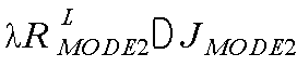
특정 모드인 MODE1의 RDcost가 JMODE1이고 JMODE1이 λRL
MODE2보다 작다면, JMODE2는 JMODE1보다 항상 크므로 MODE2의 RDcost와 상관없이 MODE1이 최적의 모드임에 해당된다.
도 4는 본 발명의 실시예에 따른 HEVC의 부호화 모드 결정방법의 흐름도이다.
도 4를 참조하면, 시작 이전에 λRL
MODE2이 미리 연산된다. 다음으로 JMODE1의 Rdcosts가 연산된다. 다음으로 JMODE1의 Rdcosts가 λRL
MODE2보다 작은지 판단된다. 판단 결과 Yes이면 최적의 모드로 MODE1이 결정되고, No이면 다음에서 MODE2의 Rdcosts가 연산된다. 다음으로 MODE1의 Rdcosts 와 MODE2 Rdcosts가 비교되고, 이 중에서 최적의 것이 결정될 수 있다. 이러한 일련의 단계들은 전체 모드에 대해서 수행되며, 전체 모드에 수행되기 전에 최적의 모드가 결정될 수 있다.
본 발명의 성능을 결정짓는 핵심 요소는 RDcost의 하한을 결정하는 방법이다. 본 발명에서 RDcost의 하한은 모드를 부호화하기 위한 신택스의 개수와 신택스의 분포에 기반하여 결정된다. 그 결정 결과는 각각의 모드마다 다르며 아래에서 각각의 모드에 대한 예시가 나타나 있다.
(1) HEVC의 인트라 PU 예측 결정 방법
HEVC에서 효율적인 화면 내 예측을 위해 35개의 인트라 예측 모드가 존재한다. 인트라 PU일 경우 35개의 예측 모드 중 최적의 예측 모드가 선택되어 부호화 된다. 인트라 예측 모드 비트를 효율적으로 부호화하기 위해 HEVC에서는 MPM(most probable mode)이 도입되었다.
MPM이란 현재 PU의 인트라 예측 모드가 주변 PU의 인트라 예측 모드와 동일할 경우 주변 모드와 동일한 인트라 예측 모드를 사용한다는 정보만 부호화하는 것을 의미한다. 따라서 현재 PU가 MPM으로 선택될 경우 인트라 예측 모드 부호화를 위한 비트가 크게 감소될 수 있다.
도 5는 HEVC에서 MPM 획득을 위한 현재의 PU 및 주변 PU를 나타내는 예시도이다.
도 5를 참조하면, 현재 PU의 왼쪽 PU와 상위 PU의 인트라 예측 모드를 사용하여 현재 PU의 MPM이 결정된다. MPM은 3개의 모드가 존재하며 따라서 MPM이 아닌 경우(Non-MPM)에는 32개의 인트라 예측 모드가 존재한다.
도 6은 HEVC인트라 PU의 MPM 결정방법의 흐름도이다.
도 6을 참조하면, 3개의 예측 모드 중 2개의 예측 모드(또는 주변의 모드가 동일할 때는 1개의 예측 모드)는 주변 모드를 이용하여 MPM을 설정하고 나머지 모드는 통계적으로 많이 발생하는 모드를 MPM으로 설정한다.
본 발명에서 고속 결정 알고리즘은 MPM인 경우와 MPM이 아닌 경우 인트라 예측 모드 비트의 차이를 이용한다. 인트라 예측에서 하나의 PU는 표1과 같은 신택스를 이용하여 부호화 한다.
현재 PU가 MPM일 경우에는 표 1에서 prev_intra_luma_flag, mpm_idx, cbf_luma, residual_coing()이 부호화 되어야 한다. 반면 현재 PU가 MPM이 아닐 경우, prev_intra_luma_flag, rem_intra_luma_pred_flag, cbf_luma, residual_coing()이 부호화 되어야 한다.
MPM과 Non-MPM 사이의 차이는 mpm_idx와 rem_intra_luma_pred_flag 의 차이이고 mpm_idx는 3개의 MPM 중 한 개를 선택하고, rem_intra_luma_pred_flag 는 32개 중 한 개를 선택하기 때문에 rem_intra_luma_pred_flag가 부호화를 위해 더 많은 비트가 필요하다. 그리고 이를 이용하여 본 발명의 실시예에 따른 HEVC의 모드 결정방법이 제안된다.
| Syntax(신택스) | Semantics(시맨틱) |
| prev_intra_luma_flag | 현재 PU가 MPM인지 아닌지를 가리키는 비트 |
| if(prev_intra_luma_flag==1)mpm_idx | MPM일 경우 3개의 MPM 중한 개를 가리키는 인덱스 비트 |
| if(prev_intra_luma_flag==0)rem_intra_lum_pred_mode | MPM이 아닐 경우 MPM을 제외한 32개의 나머지 모드 중 한 개를 표시하는 비트 |
| cbf_luma | 잔여 신호의 유무를 가리키는 비트 |
| residual_coding() | 잔여 신호 코딩을 위한 함수 |
[하나의 인트라 PU를 부호화하기 위한 신택스 및 시맨틱]
Non-MPM의 RDcost는 수학식 7과 같이 정의될 수 있다. DN
-
MPM은 Non-MPM일 때의 왜곡을 의미하고, RN-
MPM은 Non-MPM일 때의 총 비트를 의미한다. RN-
MPM은 다시 수학식 8과 같이 표현될 수 있다.


수학식 8에서 Rprev
N
-
MPM, Rrem
N
-
MPM, Rcbf
N
-
MPM, Rresidual()
N
-
MPM는 각각 prev_intra_luma_flag, rem_intra_lum_pred_mode, cbf_luma, residual_coding()을 부호화하기 위한 비트를 의미한다. 수학식 8은 수학식 9와 같이 변환될 수 있다. 수학식 9 우측항의 오른쪽 부분에서 Rresidual()
N
-
MPM이 만약 cbf가 0이면 부호화 할 필요가 없으므로 0이고, DN
-
MPM은 0보다 큰 값이다. 반면에 우측항의 왼쪽 부분은 항상 부호화해야 할 신호들이다. 왼쪽 부분의 신택스 파라미터는 CABAC(Context-adaptive binary arithmetic coding)에 의해서 부호화하기 때문에 정확한 비트 수는 실제 인코딩 되어야 알 수 있으나, 고속 알고리즘을 위해 본 발명에서는 그 값을 예측하도록 한다. Rprev
N
-
MPM와 Rcbf
N
-
MPM은 해당 신택스 정보에 대한 유무만을 판단하기 때문에 각각 1 비트로 부호화 가능하다고 볼 수 있다. Rrem
N
-
MPM는 32개의 인트라 모드 중에 한 개를 선택하는 것이고 만약 32개의 인트라 모드의 확률 분포가 평탄(uniform)하다고 가정하면 부호화하기 위해 5개의 비트가 필요하다. 따라서 수학식 9는 다시 수학식 10과 같이 변환될 수 있다.

앞서 언급하였듯이 (DN
-
MPM+λRresidual()
N
-
MPM)은 0보다 크므로 결국 Non-MPM이 가질 수 있는 RDcost의 범위는 수학식 11과 같고 Non-MPM의 RDcost의 하한은 7λ임을 알 수 있다.

따라서 만약 MPM의 RDcost JMPM이 7λ 보다 작다면 최적의 모드는 MPM임을 알 수 있고 Non-MPM을 위한 RDcost는 계산할 필요가 없음을 알 수 있다.
도 7은 본 발명의 실시예에 따른 HEVC의 인트라 예측 모드 결정방법의 흐름도이다.
도 7을 참조하면, 시작 이전에 Non-MPMs의 RDcosts의 하한이 7λ으로 연산되어 미리 결정된다. 다음으로 MPMs의 RDcosts가 연산되고, 이들 중에서 최소의 RDcost를 갖는 최적의 MPM이 선택된다. 다음으로 최적의 MPM의 RDcost(JMPM)가 7λ보다 작은지 판단된다. 판단 결과 Yes이면 최적의 모드로 MPM이 결정되고, No이면 Non-MPMs의 Rdcosts가 연산된다. 다음으로 최적의 MPM의 RDcost와 Non-MPMs의 Rdcosts가 비교되고, 이 중에서 최적의 것이 결정될 수 있다. 이러한 일련의 단계들은 전체 모드에 대해서 수행되며, 전체 모드에 수행되기 전에 최적의 모드가 결정될 수 있다.
(2) HEVC의 인트라 CU 크기 결정방법
본 발명의 다른 실시예에 따른 HEVC 인트라 CU 크기 결정 방법에 대해 설명하기로 한다.
도 8은 HEVC CU 크기 결정방법의 흐름도이다.
도 8를 참조하면, 하나의 CU는 4개의 sub-CU로 분할 될 수 있으며 분할 유무는 CU의 RDcost와 sub-CU의 RDcost의 합과의 비교에 의해 결정된다. 즉 CU의 RDcost가 4개 sub-CU의 RDcost의 합보다 작으면, 현재 CU는 더 이상 분할 되지 않는다. 그 반대일 경우는 CU는 분할되어 sub-CU가 최적의 CU가 된다.
본 발명의 실시예에 따른 HEVC CU 크기 결정방법에서는 한 개의 인트라 CU가 가지는 신택스를 분석하고 이에 기반하여 4개의 sub-CU의 RDcost 합의 하한을 구하도록 한다. 상위 CU의 RDcost와 sub-CU의 RDcost 합의 하한을 비교하여 인트라 CU의 분할 유무를 결정하도록 한다. 자세한 사항은 아래와 같다.
| Syntax(신택스) | Semantics (시맨틱) |
| prev_intra_luma_flag | 현재 PU가 MPM인지 아닌지를 가리키는 비트 |
| if(prev_intra_luma_flag==1)mpm_idx | MPM일 경우 3개의 MPM 중 한 개를 가리키는 인덱스 비트 |
| if(prev_intra_luma_flag==0)rem_intra_lum_pred_mode | MPM이 아닐 경우 MPM을 제외한 32개의 나머지 모드 중 한 개를 표시하는 비트 |
| intra_chroma_pred_mode | 색차 신호의 예측 모드를 가리키는 비트 |
| split_transform_flag | TU의 분할 유무를 가리키는 비트 |
| cbf_luma | Luma 잔여 신호의 유무를 가리키는 비트 |
| cbf_cb | Chroma(Cb) 잔여 신호의 유무를 가리키는 비트 |
| cbf_cr | Chroma(Cr) 잔여 신호의 유무를 가리키는 비트 |
| split_cu_flag | CU의 분할 유무를 가리키는 비트 |
| residual_coding() | 잔여 신호 코딩을 위한 함수 |
[하나의 인트라 CU를 구성하는 신택스 구성요소]
표 2에서, mpm_idx와 rem_intra_lum_pred_mode는 MPM 유무에 따라 두 개 중 한 개만 선택된다. 따라서 잔여 신호 부호화인 residual_coding()이 제외된다고 가정하면 하나의 CU당 최소 8개의 신택스 요소가 필요함을 알 수 있다. 따라서 4개의 sub-CU는 최소한 총 32개의 신택스 요소가 부호화 되어야 한다. 만약 한 개의 신택스가 최소 1 비트 이상이 필요하다고 가정하면 4개의 sub-CU를 위해서는 최소 32비트 이상이 필요함을 알 수 있다. 그리고 왜곡은 항상 0보다 크므로 4개의 sub-CU의 RDcost의 합은 항상 32λ보다 크다. 따라서 는 4개의 sub-CU의 RDcost의 합의 하한이 된다.
최종적으로 본 발명에서는 CU의 RDcost가 sub-CU의 RDcost 합의 하한인 32λ 보다 작으면 CU의 RDcost가 항상 sub-CU의 RDcost의 합보다 작으므로 sub-CU로 더 이상 분할되지 않는다.
도 9는 본 발명의 실시예에 따른 HEVC의 인트라 CU 크기 결정방법의 흐름도이다.
sub-CU의 RDcost의 하한은 CU 크기에 따라 변할 수 있다. 이는 부호화의 제약 조건으로 인하여 특정 신택스 요소는 부호화 할 필요가 없기 때문에 발생한다. 예를 들어 HEVC에서는 8×8이 최소 CU단위이기 때문에 sub-CU의 크기가 8×8이면 더 이상 CU를 분할할 필요가 없으므로 split_cu_flag는 부호화 할 필요가 없다. 따라서 이 경우의 8×8 sub-CU의 RDcost의 하한은 28λ가 된다.
*(3) 고속 인터 CU/PU 모드 결정 방법
도 10은 HEVC 인터 모드 종류를 나타내는 예시도이다.
HEVC는 효율적인 인터 예측을 위하여 도 11과 같이 SKIP, MERGE, INTER 2N×2N, INTER 2N×N, INTER N×2N, INTER N×N 등 다양한 PU 모드를 제공한다. 각각의 PU 모드를 부호화 하기 위한 신택스 요소나 부호화하기 위해 필요한 신택스 개수는 서로 상이하다.
이하 상기 차이점을 이용하여 본 발명의 다른 실시예에 따른 HEVC 인터 CU 및 PU 모드 결정방법에 대해 설명하기로 한다.
각각의 모드에 대한 필요한 신택스 요소의 최소 개수를 추정하고 이에 기반 하여 모드 결정과정을 미리 종료하는 방법이 개시된다.
| Syntax(신택스) | Semantics (시맨틱) |
| cu_skip_flag | 현재 CU를 SKIP으로 부호할지 유무를 가리키는 비트 |
| merge_idx | SKIP을 위한 움직임 벡터 후보 중 한 개를 가리키는 인덱스 비트 |
[SKIP CU를 부호화하기 위해 필요한 신택스 및 시맨틱]
SKIP CU를 위해 필요한 신택스 요소는 위의 표 3과 같다.
그리고 SKIP 이 아닐 경우 (Non-SKIP) 필요한 인터 CU 신택스 요소는 아래 표 4, 표 5 및 표 6과 같다.
| Syntax (신택스) | Semantics (시맨틱) |
| cu_skip_flag | 현재 CU를 SKIP으로 부호할지 유무를 가리키는 비트 |
| pred_mode_flag | 현재 CU가 인트라 CU인지 인터 CU인지 가리키는 비트 |
| part_mode | 인터 모드의 PU 타입을 가리키는 비트 |
| prediction_unit() | PU를 부호화 하기 위한 정보 |
| rqt_root_cbf | 현재 CU에 Luma, Cb, Cr의 잔여 신호가 포함되어 있는지 아닌지를 가리키는 비트 |
| transform_tree() | 잔여 신호를 부호화하기 위한 정보 |
[Non-SKIP CU를 부호화하기 위해 필요한 신택스 및 시맨틱]
| Syntax (신택스) | Semantics (시맨틱) |
| merge_flag | 현재 PU가 MERGE인지 아닌지를 가리키는 비트 |
| merge_idx | MERGE를 위한 움직임 벡터 후보 중 한 개를 가리키는 인덱스 비트 |
| inter_pred_idc | 단방향 예측 중 List0만 사용할지 List1만 사용할지 아니면 쌍방향 예측을 사용할지를 가리키는 비트 |
| ref_idx_10 | 현재 PU를 위한 List0 참조 번호를 가리키는 비트 |
| mvp_10_flag | List0의 움직임 벡터 예측기 후보 중 한 개를 가리키는 비트 |
| ref_idx_11 | 현재 PU를 위한 List1 참조 번호를 가리키는 비트 |
| mvp_11_flag | List1의 움직임 벡터 예측기 후보 중 한 개를 가리키는 비트 |
| mvd_coding() | 움직임 벡터 코딩을 위한 함수 |
[prediction_unit()이 포함하는 신택스 및 시맨틱]
| Syntax (신택스) | Semantics (시맨틱) |
| abs_mvd_greater()_flag[0] | x 방향 움직임 벡터의 절대 값이 0보다 큰지를 가리키는 비트 |
| abs_mvd_greater()_flag[1] | y 방향 움직임 벡터의 절대 값이 0보다 큰지를 가리키는 비트 |
| abs_mvd_greater1_flag[0] | x 방향 움직임 벡터의 절대 값이 1보다 큰지를 가리키는 비트 |
| abs_mvd_greater1_flag[1] | y 방향 움직임 벡터의 절대 값이 1보다 큰지를 가리키는 비트 |
| abs_mvd_minus2[0] | x 방향 움직임 벡터의 절대 값에 2를 뺀 값 |
| mvd_sign_flag[0] | x 방향 움직임 벡터의 부호 |
| abs_mvd_minus2[1] | y 방향 움직임 벡터의 절대 값에 2를 뺀 값 |
| mvd_sign_flag[1] | y 방향 움직임 벡터의 부호 |
[mvd_coding()이 포함하는 신택스 및 시맨틱]
SKIP을 위해 필요한 총 신택스의 수는 2개이고, 각각의 신택스 요소를 1비트로 부호화 한다고 가정하면 필요한 최소 비트 수는 2이다. 따라서 만약 다른 CU 모드의 RDcost가 2λ보다 작으면 SKIP모드의 RDcost를 연산할 필요가 없다.
표 4의 prediction_unit()이 포함하는 정보는 위의 표 5에 나타난다. merge_flag는 현재 PU가 MERGE인지 아닌지를 가리킨다. 만약 MERGE이면 merge_idx를 부호화하며, MERGE가 아닌 경우 inter_pred_idc, ref_idx_l0, mvp_l0_flag, ref_idx_l1, mvp_l1_flag, mvd_coding() 등을 부호화 한다. 따라서 현재 PU가 MERGE인지 아닌지에 따라서 부호화될 신택스 요소의 수가 달라진다. 또한, prediction_unit()은 PU마다 한 개씩 부호화 된다. 예를 들어 2N×2N의 경우에는 하나의 CU에 한 개의 PU가 존재하고, 2N×N 또는 N×2N인 경우에는 2개의 PU가 존재한다. N×N의 경우에는 총 4개의 PU가 존재한다. 슬라이스 유형에 따라 prediction_unit()에 포함될 수 있는 신택스 요소가 다르다. 예를 들어 P 슬라이스의 경우에는 전방향으로만 예측할 수 있기 때문에 List0에 연관된 신택스 요소만 필요하다. 반면에 B 슬라이스의 경우에는 양방향 및 전방향으로 예측이 가능하기 때문에 List0및 List1에 연관된 신택스 요소가 모두 필요하다. 이런 다양한 특징들을 조합하여 본 발명에서는 HEVC의 인터 모드 결정방법을 위한 RDcost의 하한을 결정한다.
mvd_coding()이 포함하는 신택스 요소는 표 6이 보여준다. abs_mvd_greater1_flag[0] 및 mvd_sign_flag[0]는 abs_mvd_greater0_flag[0]가 1인 경우에 존재하는 값이고, abs_mvd_greater1_flag[1] 및 mvd_sign_flag[1]는 abs_mvd_greater0_flag[1]가 1인 경우에 존재하는 값이다. abs_mvd_minus2[0]는 abs_mvd_greater0_flag[0] 및 abs_mvd_greater1_flag[0]가 모두 1이어야 존재하는 값이고, abs_mvd_minus2[1]는 abs_mvd_greater0_flag[1] 및 abs_mvd_greater1_flag[1]이 모두 1이어야 존재하는 값이다. 따라서 mvd_coding()는 움직임 벡터에 따라 최소 2개부터 최대 8개까지의 신택스 요소가 부호화 과정에 요구된다.
표 4 내지 표 6까지의 정보를 조합하여 본 발명에서는 SKIP을 제외한 다른 인터 모드에 대한 RDcost의 하한을 결정된다. 본 발명의 실시예에 따른 HEVC의 모드 결정방법은 B 슬라이스 및 P 슬라이스 모두에 적용될 수 있다.
이하 B 슬라이스에 대한 예시에 대해 설명하기로 한다.
RDcost의 하한은 신택스 요소의 수에 비례하여 결정되므로 prediction_unit()의 수가 작을수록 RDcost의 하한은 낮아진다. 따라서 prediction_unit()의 수가 작은 순서대로 RDcost의 하한이 연산된다. 각 인터 모드 유형마다 prediction_unit()의 수는 아래 표 7과 같다.
| part_mode | prediction_unit() 수 |
| 2Nx2N | 1 |
| 2NxN, Nx2N | 2 |
| NxN | 4 |
| nRx2N, nLx2N,2NxnU, 2NxnD | 2 |
[인터 PU 모드에 따른 prediction_unit()의 수]
본 발명에서는 먼저 2N×2N의 RDcost 하한이 연산되고, 그 다음 2N×N, N×2N, nR×2N, nL×2N, 2N×nU, 2N×nD의 하한이 연산되고, 마지막에 N×N의 RDcost 하한이 연산된다. 상기 RDcost의 하한들은 비교 기준들에 해당되고, SKIP 모드의 RDcost는 제1 비교 타겟에 해당된다.
2N×2N은 MERGE모드인 경우와 INTER 모드인 경우로 나눌 수 있다. 먼저 2N×2N MERGE를 부호화 하기 위해 필요한 syntax 요소는 표 8과 같다.
| Syntax (신택스) | 필요 비트 | ||
| cu_skip_flag | |||
| pred_mode | |||
| part_mode | |||
| prediction_unit() | |||
| merge_idx | 1 | ||
| transform_tree() | |||
| cbf_luma | 1 | ||
| cbf_cb | 1 | ||
| cbf_cr | 1 | ||
| transform_unit() | 1 | ||
[2N×2N MERGE PU를 부호화하기 위해 필요한 신택스]
표 8과 같이 총 10개의 신택스 요소가 필요하며 따라서 각각의 신택스 요소를 최소 1비트로 코딩한다고 가정하였을 때 최소 10비트가 필요하다. 따라서 만약 다른 모드의 RDcost가 10λ보다 작으면 2N×2N MERGE모드의 RDcost를 연산할 필요가 없다.
| Syntax (신택스) | ||
| cu_skip_flag | ||
| pred_mode_flag | ||
| part_mode | ||
| prediction_unit() | merge_flag | 1 |
| inter_pred_idc | 1 | |
| ref_idx_10 | 1 | |
| mvp_10_flag | 1 | |
| mvd_coding() | 2~8 | |
| ref_idx_11 | 1 | |
| mvp_11_flag | 1 | |
| mvd_coding() | 2~8 | |
| rqt_root_cbf | ||
[2N×2N INTER PU를 부호화하기 위해 필요한 신택스]
2N×2N INTER모드를 부호화하기 위해 필요한 신택스 요소는 위의 표 9와 같다.
B 슬라이스를 가정하였으므로 전방향, 후방향, 및 쌍방향 예측이 수행될 수 있다. 일반적으로 쌍방향 예측의 효율이 가장 높으므로 본 발명에서는 쌍방향 예측이 사용될 경우를 가정한다. 또한 움직임 벡터 차이를 부호화하는 함수인 mvd_coding()은 2개부터 8개의 신택스를 요구하며, 하한의 연산이므로 최소인 2개의 신택스가 필요한 것으로 결정된다. 그리고 모든 잔여 신호가 0이라고 가정하면 rqt_root_cbf만이 부호화 되면 되고 이 경우 transform_tree()는 부호화의 필요성이 없다. 이럴 경우 필요한 비트 수는 총 14비트이다. 따라서 만약 다른 모드의 RDcost가 14λ보다 작으면 2N×2N Inter PU모드의 RDcost를 연산할 필요가 없다.
2N×N, N×2N, nR×2N, nL×2N, 2N×nD, 2N×nU는 모두 2개의 prediction unit()을 가지므로 RDcost 하한을 공통을 사용할 수 있다. 2N×2N 모드에서 본 것처럼 한 prediction_unit()을 부호화기 위해 필요한 신택스 요소는 MERGE일 경우 2개이고 MERGE가 아닐 경우에는 10개이다. 그리고 prediction_unit()을 제외하고 부호화해야 할 최소의 신택스 요소는 cu_skip_flag, pred_mode_flag, part_mode, rqt_root_cbf로 4개이다. 따라서 prediction_unit()이 2개일 때 최소의 신택스 개수는 prediction_unit()이 모두 MERGE인 경우고, 이 경우의 총 신택스 요소의 수는 4+2×2 = 8개이다. 따라서 만약 다른 모드의 RDcost가 보다 작으면 2N×N, N×2N, nR×2N, nL×2N, 2N×nD, 2N×nU 모드의 RDcost를 연산할 필요가 없다.
2N×N, N×2N, nR×2N, nL×2N, 2N×nD, 2N×nU에서 하나 이상의 PU가 INTER모드일 수 있다. 이 경우의 하한은 한 개의 prediction_unit()은 INTER이고 다른 한 개는 MERGE일 경우로 볼 수 있으며 RDcost의 하한은 MERGE를 위한 2개 신택스 요소, INTER를 위한 신택스 요소 10개, prediction_unit() 이외의 신택스 요소로 총 16개의 신택스 요소가 필요하다. 따라서 만약 다른 모드의 RDcost가 보다 작으면 2N×N, N×2N, nR×2N, nL×2N, 2N×nD, 2N×nU 모드의 INTER에 대한 RDcost를 연산할 필요가 없다.
N×N은 4개의 prediction unit()을 가진다. prediction_unit()이 4개일 때 최소의 신택스 개수는 prediction_unit()이 모두 MERGE인 경우고, 이 경우의 총 신택스 요소의 수는 4+4×2 = 12개이다. 따라서 만약 다른 모드의 RDcost가 보다 작으면 N×N 모드의 RDcost를 연산할 필요가 없다.
2N×N의 경우처럼 N×N에서도 하나 이상의 INTER PU 모드가 존재할 수 있다. N×N INTER의 RDcost 연산의 유무를 결정하기 위해 본 발명에서는 2개의 prediction_unit()은 INTER이고 2개의 prediction_unit()은 MERGE라고 가정하였다. 이 경우 RDcost의 하한은 MERGE를 위한 2개 신택스 요소, INTER를 위한 신택스 요소 10개, prediction_unit() 이외의 신택스 요소로 총 28개의 신택스 요소가 필요하다. 따라서 만약 다른 모드의 RDcost가 28λ보다 작으면 N×N 모드의 INTER에 대한 RDcost를 연산할 필요가 없다.
도 11은 본 발명의 실시예에 따른 B-Slice를 위한 HEVC의 인터 CU/PU 모드 결정방법의 흐름도이다.
도 11을 참조하면, 먼저 SKIP 모드의 RDcost가 산출된 후 SKIP 모드의 RDcost가 10λ보다 작으면 전체 인터 모드 과정이 종료되고 SKIP 모드가 최적의 모드로 선택된다. 만약 SKIP 모드의 RDcost가 10λ보다 크면 MERGE의 RDcost이 연산되고 SKIP 모드와 MERGE의 RDcost 중 가장 작은 RDcost가 제2 비교 타겟(Jtemp-best)으로 결정된다. 제2 비교 타겟(Jtemp-best)이 만약 14λ보다 작으면 2N×2N INTER에 대한 RDcost가 스킵된다. 만약 제2 비교 타겟(Jtemp-best)이 8λ보다 작으면 인터 모드 과정이 종료되고 제2 비교 타겟(Jtemp-best)을 가진 모드를 최적의 모드로 선택한다. 만약 제2 비교 타겟(Jtemp-best)이 8λ보다 크고 16λ보다 작으면 N×2N의 MERGE에 대한 RDcost만이 연산되고 제2 비교 타겟(Jtemp-best)이 16λ보다 크면 N×2N의 MERGE와 INTER에 대한 RDcost이 연산된다. N×2N의 RDcost가 제2 비교 타겟(Jtemp-best)보다 작으면 N×2N의 RDcost가 제2 비교 타겟(Jtemp-best)으로 업데이트된다. 나머지 모드에 대하여도 N×2N의 방법과 동일한 방법이 적용된다.
도 12는 본 발명의 실시예에 따른 HEVE 부호화의 P-Slice를 위한 인터 CU/PU 모드 결정방법의 흐름도이다.
도 13을 참조하면, P-Slice의 임계치는 B-Slice에서의 방법과 동일하게 산출 된다. P-Slice는 단방향 예측만 사용되므로 B-Slice에 비해 신택스 요소의 수가 작으므로 임계치가 B-Slice에 비해 낮은 것이 특징이다. 도 12의 설명과 중복되는 설명은 생략하기로 한다.
본 발명에 따른 모드 결정방법들은 다양한 컴퓨터 수단을 통해 수행될 수 있는 프로그램 명령 형태로 구현되어 컴퓨터 판독 가능 매체에 기록될 수 있다. 컴퓨터 판독 가능 매체는 프로그램 명령, 데이터 파일, 데이터 구조 등을 단독으로 또는 조합하여 포함할 수 있다. 컴퓨터 판독 가능 매체에 기록되는 프로그램 명령은 본 발명을 위해 특별히 설계되고 구성된 것들이거나 컴퓨터 소프트웨어 당업자에게 공지되어 사용 가능한 것일 수도 있다.
컴퓨터 판독 가능 매체의 예에는 롬(rom), 램(ram), 플래시 메모리(flash memory) 등과 같이 프로그램 명령을 저장하고 수행하도록 특별히 구성된 하드웨어 장치가 포함된다. 프로그램 명령의 예에는 컴파일러(compiler)에 의해 만들어지는 것과 같은 기계어 코드뿐만 아니라 인터프리터(interpreter) 등을 사용해서 컴퓨터에 의해 실행될 수 있는 고급 언어 코드를 포함한다. 상술한 하드웨어 장치는 본 발명의 동작을 수행하기 위해 적어도 하나의 소프트웨어 모듈로 작동하도록 구성될 수 있으며, 그 역도 마찬가지이다.
이상 본 발명의 바람직한 실시예를 참조하여 설명하였지만, 해당 기술 분야의 숙련된 당업자는 하기의 특허 청구의 범위에 기재된 본 발명의 사상 및 영역으로부터 벗어나지 않는 범위 내에서 본 발명을 다양하게 수정 및 변경시킬 수 있음을 이해할 수 있을 것이다.
본 발명에 의하면, 부호화 성능의 손실 없이 HEVC의 모드 결정의 복잡도를 낮춤으로써 고속의 부호화가 가능하다.
Claims (10)
- 고효율 비디오 부호화(High Efficiency Video Coding, HEVC)의 모드 결정방법에 있어서,부호화에 필요한 신택스(syntax) 요소 및 신택스(syntax) 개수에 기반하여 일반 부호화 모드의 율-왜곡비용의 하한을 연산하는 단계;부호화 모드들 중에서 어느 하나의 모드를 현재 부호화 모드로 선택하고, 선택된 현재 부호화 모드의 율-왜곡 비용을 연산하는 단계;상기 현재 부호화 모드의 율-왜곡 비용과 상기 율-왜곡 비용의 하한을 비교하는 단계; 및상기 현재 부호화 모드의 율-왜곡 비용이 상기 율-왜곡 비용의 하한보다 작은 경우,상기 현재 부호화 모드를 최적의 부호화 모드로 선택하는 단계를 포함하는, 고효율 비디오 부호화 모드 결정방법.
- 청구항 1에서,상기 현재 부호화 모드의 율-왜곡 비용이 상기 율-왜곡 비용의 하한보다 작지 않은 경우,상기 일반 부호와 모드의 율-왜곡 비용을 연산하는 단계;상기 일반 부호화 모드의 율-왜곡 비용과 상기 현재 부호화 모드의 율-왜곡 비용을 비교하고, 이들 중에서 최적의 부호화 모드를 선택하는 단계를 더 포함하는, 고효율 비디오 부호화 모드 결정방법.
- 청구항 2에 있어서,상기 율-왜곡 비용의 하한은,부호화 모드들이 가질 수 있는 율-왜곡 비용(rate-distortion cost, RDcost)의 최소값으로서, 실제 부호화 시에 소요되는 비트 수에 기반하는, 고효율 비디오 부호화 모드 결정방법.
- 고효율 비디오 부호화(High Efficiency Video Coding, HEVC)의 인트라 (intrapicture) PU(prediction unit) 예측 모드 결정방법에 있어서,부호화에 필요한 신택스(syntax) 요소 및 신택스(syntax) 개수에 기반하여 MPM(most probable mode)이 아닌(Non-MPM) 모드의 율-왜곡비용의 하한을 7λ으로 연산하는 단계, 여기서 λ는 라그랑지안 계수(lagrangian multiplier);인트라 PU 예측 모드 중에서 MPM 모드들의 율-왜곡 비용을 연산하고, 이 중에서 최소 율-왜곡 비용을 갖는 최적의 MPM 모드를 찾는 단계;상기 최소 율-왜곡 비용과 상기 율-왜곡비용의 하한을 비교하는 단계; 및상기 최소 율-왜곡 비용이 상기 율-왜곡비용의 하한보다 작은 경우,상기 최적의 MPM 모드를 예측 모드로 선택하는 단계를 포함하는, 고효율 비디오 부호화 모드 결정방법.
- 청구항 4에서,상기 최소 율-왜곡 비용이 상기 율-왜곡비용의 하한보다 작지 않은 경우,MPM이 아닌 모드의 율-왜곡 비용을 계산하는 단계; 및상기 MPM이 아닌 모드의 율-왜곡 비용과 상기 최소 율-왜곡 비용을 비교하고, 이들 중에서 최적의 모드를 선택하는 단계를 더 포함하는, 고효율 비디오 부호화 모드 결정방법.
- 고효율 비디오 부호화(High Efficiency Video Coding, HEVC)의 인트라 CU 크기 결정방법에 있어서,부호화에 필요한 신택스(syntax) 요소 및 신택스(syntax) 개수에 기반하여 하나의 CU가 분할되어 형성된 4개의 sub-CU들의 율-왜곡비용의 하한을 32λ으로 연산하는 단계, 여기서 λ는 라그랑지안 계수(lagrangian multiplier);현재 CU의 율-왜곡 비용을 연산하는 단계; 및상기 율-왜곡비용의 하한과 상기 현재 CU의 율-왜곡비용을 비교하는 단계를 포함하되,상기 현재 CU의 율-왜곡 비용이 상기 율-왜곡비용의 하한보다 작은 경우,상기 현재 CU는 분할되지 않는, 고효율 비디오 부호화 모드 결정방법.
- 청구항 6에서,상기 현재 CU의 율-왜곡 비용이 상기 율-왜곡비용의 하한보다 작지 않은 경우,상기 sub-CU들의 율-왜곡 비용들의 합을 연산하는 단계; 및상기 현재 CU의 율-왜곡 비용과 상기 sub-CU들의 율-왜곡 비용들의 합을 비교하는 단계를 더 포함하되,상기 현재 CU의 율-왜곡 비용이 상기 sub-CU들의 율-왜곡 비용들의 합보다 작은 경우, 상기 현재 CU는 분할되지 않고,상기 현재 CU의 율-왜곡 비용이 상기 sub-CU들의 율-왜곡 비용들의 합보다 작지 않은 경우, 상기 현재 CU는 분할되는, 고효율 비디오 부호화 모드 결정방법.
- 고효율 비디오 부호화(High Efficiency Video Coding, HEVC)의 인터 CU/PU 모드 결정방법에 있어서,(a) 부호화에 필요한 신택스(syntax) 요소 및 신택스(syntax) 개수에 기반하여, 비교 기준으로서 2N×2N MERGE, 2N×2N INTER, N×2N MERGE, N×2N INTER, 비대칭 모션 분할(asymmetric motion partition, AMP), N×N MERGE 및 N×N INTER 모드 부호화의 율-왜곡 비용의 하한을 연산하는 단계;(b) 제1 비교 타겟으로서 SKIP 모드를 선택하고, SKIP 모드의 율-왜곡 비용을 연산하는 단계;(c) 상기 제1 비교 타겟의 율-왜곡 비용이 상기 비교 기준인 2N×2N MERGE 모드의 율-왜곡 비용의 하한보다 작은지 비교하는 단계;(d) 상기 제1 비교 타겟의 율-왜곡 비용이 상기 비교 기준보다 더 작은 경우 비교 타겟을 선택하고,그렇지 않은 경우 상기 비교 기준의 율-왜곡 비용을 연산하고,비교 타겟의 율-왜곡 비용과 비교 기준인 2N×2N MERGE의 율-왜곡 비용을 비교하고, 이 중에서 최적의 율-왜곡 비용을 갖는 모드를 제2 비교 타겟으로 업데이트하는 단계;순서대로 나머지 2N×2N INTER, N×2N MERGE, N×2N INTER, 비대칭 모션 분할(AMP), N×N MERGE 및 N×N INTER 모드에 대해서, 상기 제2 비교 타겟의 율-왜곡 비용을 이용하여 상기 (c) 및 (d)를 반복함으로써 제2 비교 타겟이 최적의 율-왜곡 비용을 갖는 모드가 되도록 제2 비교 타겟을 계속 업데이트 하고,최종 업데이트된 제2 비교 타겟의 모드를 선택하는 단계를 포함하는, 고효율 비디오 부호화 모드 결정방법.
- 청구항 8에서,신택스 요소 prediction_unit에 포함될 수 있는 신택스 요소에 따라, B-Slice를 위한 CU/PU 모드 결정 또는 P-Slice를 위한 CU/PU 모드 결정을 포함하는, 고효율 비디오 부호화 모드 결정방법.
- 청구항 8에서,SKIP 모드의 율-왜곡 비용이 2N×2N MERGE 모드의 율-왜곡 비용의 하한, 10λ보다 작은 경우, SKIP 모드를 선택하고,제2 비교 타겟의 율-왜곡 비용이 N×2N MERGE 모드의 율-왜곡 비용의 하한, 8λ보다 작은 경우, 최적의 율-왜곡 비용을 갖는 제2 비교 타겟을 선택하고,제2 비교 타겟의 율-왜곡 비용이 N×N MERGE 모드의 율-왜곡 비용의 하한, 12λ보다 작은 경우, 최적의 율-왜곡 비용을 갖는 제2 비교 타겟을 선택하는, 고효율 비디오 부호화 모드 결정방법.
Applications Claiming Priority (2)
| Application Number | Priority Date | Filing Date | Title |
|---|---|---|---|
| KR10-2016-0175385 | 2016-12-21 | ||
| KR1020160175385A KR101967028B1 (ko) | 2016-12-21 | 2016-12-21 | 고효율 비디오 부호화 모드 결정방법 및 결정장치 |
Publications (1)
| Publication Number | Publication Date |
|---|---|
| WO2018117334A1 true WO2018117334A1 (ko) | 2018-06-28 |
Family
ID=62626735
Family Applications (1)
| Application Number | Title | Priority Date | Filing Date |
|---|---|---|---|
| PCT/KR2017/002190 Ceased WO2018117334A1 (ko) | 2016-12-21 | 2017-02-28 | 고효율 비디오 부호화 모드 결정방법 및 결정장치 |
Country Status (2)
| Country | Link |
|---|---|
| KR (1) | KR101967028B1 (ko) |
| WO (1) | WO2018117334A1 (ko) |
Cited By (11)
| Publication number | Priority date | Publication date | Assignee | Title |
|---|---|---|---|---|
| CN110087087A (zh) * | 2019-04-09 | 2019-08-02 | 同济大学 | Vvc帧间编码单元预测模式提前决策及块划分提前终止方法 |
| CN110139106A (zh) * | 2019-04-04 | 2019-08-16 | 中南大学 | 一种视频编码单元分割方法及其系统、装置、存储介质 |
| CN111654696A (zh) * | 2020-04-24 | 2020-09-11 | 北京大学 | 一种帧内的多参考行预测方法、装置、存储介质及终端 |
| CN111901602A (zh) * | 2020-08-07 | 2020-11-06 | 北京奇艺世纪科技有限公司 | 视频数据编码方法、装置、计算机设备和存储介质 |
| CN111918058A (zh) * | 2020-07-02 | 2020-11-10 | 北京大学深圳研究生院 | 硬件友好的帧内预测模式快速确定方法、设备及存储介质 |
| CN112702598A (zh) * | 2020-12-03 | 2021-04-23 | 浙江智慧视频安防创新中心有限公司 | 基于位移操作进行编解码的方法、装置、电子设备及介质 |
| US20220191477A1 (en) * | 2020-02-17 | 2022-06-16 | Tencent Technology (Shenzhen) Company Limited | Coding mode selection method and apparatus, and electronic device and computer-readable medium |
| CN116033162A (zh) * | 2022-12-30 | 2023-04-28 | 中星电子股份有限公司 | 率失真编码模式的选择方法及装置、编码方法及系统 |
| CN116170594A (zh) * | 2023-04-19 | 2023-05-26 | 中国科学技术大学 | 一种基于率失真代价预测的编码方法和装置 |
| WO2023147780A1 (zh) * | 2022-02-07 | 2023-08-10 | 杭州未名信科科技有限公司 | 视频帧的编码模式筛选方法、装置及电子设备 |
| WO2025076795A1 (zh) * | 2023-10-12 | 2025-04-17 | Oppo广东移动通信有限公司 | 编解码方法、码流、编码器、解码器以及存储介质 |
Families Citing this family (2)
| Publication number | Priority date | Publication date | Assignee | Title |
|---|---|---|---|---|
| WO2020171673A1 (ko) * | 2019-02-24 | 2020-08-27 | 엘지전자 주식회사 | 인트라 예측을 위한 비디오 신호의 처리 방법 및 장치 |
| US20220124309A1 (en) * | 2019-02-28 | 2022-04-21 | Lg Electronics Inc. | Unified mpm list-based intra prediction |
Citations (5)
| Publication number | Priority date | Publication date | Assignee | Title |
|---|---|---|---|---|
| KR20150099165A (ko) * | 2014-02-21 | 2015-08-31 | 연세대학교 산학협력단 | Tsm 율-왜곡 최적화 방법, 그를 이용한 인코딩 방법 및 장치, 그리고 영상 처리 장치 |
| KR20150115833A (ko) * | 2013-02-01 | 2015-10-14 | 퀄컴 인코포레이티드 | 인트라 예측을 위한 모드 결정 단순화 |
| KR20150115886A (ko) * | 2013-02-06 | 2015-10-14 | 퀄컴 인코포레이티드 | 감소된 저장에 의한 인트라 예측 모드 결정 |
| KR20160106348A (ko) * | 2015-03-02 | 2016-09-12 | 한국전자통신연구원 | 비디오 부호화 방법 및 그 장치 |
| KR20160110589A (ko) * | 2015-03-09 | 2016-09-22 | 한국전자통신연구원 | Hevc 고속 부호화 모드 결정을 위한 적응적 부호화 모드 순서 정렬 방법 및 장치 |
Family Cites Families (1)
| Publication number | Priority date | Publication date | Assignee | Title |
|---|---|---|---|---|
| KR101359496B1 (ko) * | 2008-08-06 | 2014-02-11 | 에스케이 텔레콤주식회사 | 부호화 모드 결정 방법 및 장치와 그를 이용한 영상 부호화장치 |
-
2016
- 2016-12-21 KR KR1020160175385A patent/KR101967028B1/ko active Active
-
2017
- 2017-02-28 WO PCT/KR2017/002190 patent/WO2018117334A1/ko not_active Ceased
Patent Citations (5)
| Publication number | Priority date | Publication date | Assignee | Title |
|---|---|---|---|---|
| KR20150115833A (ko) * | 2013-02-01 | 2015-10-14 | 퀄컴 인코포레이티드 | 인트라 예측을 위한 모드 결정 단순화 |
| KR20150115886A (ko) * | 2013-02-06 | 2015-10-14 | 퀄컴 인코포레이티드 | 감소된 저장에 의한 인트라 예측 모드 결정 |
| KR20150099165A (ko) * | 2014-02-21 | 2015-08-31 | 연세대학교 산학협력단 | Tsm 율-왜곡 최적화 방법, 그를 이용한 인코딩 방법 및 장치, 그리고 영상 처리 장치 |
| KR20160106348A (ko) * | 2015-03-02 | 2016-09-12 | 한국전자통신연구원 | 비디오 부호화 방법 및 그 장치 |
| KR20160110589A (ko) * | 2015-03-09 | 2016-09-22 | 한국전자통신연구원 | Hevc 고속 부호화 모드 결정을 위한 적응적 부호화 모드 순서 정렬 방법 및 장치 |
Cited By (19)
| Publication number | Priority date | Publication date | Assignee | Title |
|---|---|---|---|---|
| CN110139106B (zh) * | 2019-04-04 | 2023-01-17 | 中南大学 | 一种视频编码单元分割方法及其系统、装置、存储介质 |
| CN110139106A (zh) * | 2019-04-04 | 2019-08-16 | 中南大学 | 一种视频编码单元分割方法及其系统、装置、存储介质 |
| CN110087087A (zh) * | 2019-04-09 | 2019-08-02 | 同济大学 | Vvc帧间编码单元预测模式提前决策及块划分提前终止方法 |
| CN110087087B (zh) * | 2019-04-09 | 2023-05-12 | 同济大学 | Vvc帧间编码单元预测模式提前决策及块划分提前终止方法 |
| US12069249B2 (en) * | 2020-02-17 | 2024-08-20 | Tencent Technology (Shenzhen) Company Limited | Coding mode selection method and apparatus, and electronic device and computer-readable medium |
| US20220191477A1 (en) * | 2020-02-17 | 2022-06-16 | Tencent Technology (Shenzhen) Company Limited | Coding mode selection method and apparatus, and electronic device and computer-readable medium |
| CN111654696A (zh) * | 2020-04-24 | 2020-09-11 | 北京大学 | 一种帧内的多参考行预测方法、装置、存储介质及终端 |
| CN111654696B (zh) * | 2020-04-24 | 2022-08-05 | 北京大学 | 一种帧内的多参考行预测方法、装置、存储介质及终端 |
| CN111918058A (zh) * | 2020-07-02 | 2020-11-10 | 北京大学深圳研究生院 | 硬件友好的帧内预测模式快速确定方法、设备及存储介质 |
| CN111918058B (zh) * | 2020-07-02 | 2022-10-28 | 北京大学深圳研究生院 | 硬件友好的帧内预测模式快速确定方法、设备及存储介质 |
| CN111901602B (zh) * | 2020-08-07 | 2022-09-30 | 北京奇艺世纪科技有限公司 | 视频数据编码方法、装置、计算机设备和存储介质 |
| CN111901602A (zh) * | 2020-08-07 | 2020-11-06 | 北京奇艺世纪科技有限公司 | 视频数据编码方法、装置、计算机设备和存储介质 |
| CN112702598A (zh) * | 2020-12-03 | 2021-04-23 | 浙江智慧视频安防创新中心有限公司 | 基于位移操作进行编解码的方法、装置、电子设备及介质 |
| CN112702598B (zh) * | 2020-12-03 | 2024-06-04 | 浙江智慧视频安防创新中心有限公司 | 基于位移操作进行编解码的方法、装置、电子设备及介质 |
| WO2023147780A1 (zh) * | 2022-02-07 | 2023-08-10 | 杭州未名信科科技有限公司 | 视频帧的编码模式筛选方法、装置及电子设备 |
| CN116033162A (zh) * | 2022-12-30 | 2023-04-28 | 中星电子股份有限公司 | 率失真编码模式的选择方法及装置、编码方法及系统 |
| CN116170594A (zh) * | 2023-04-19 | 2023-05-26 | 中国科学技术大学 | 一种基于率失真代价预测的编码方法和装置 |
| CN116170594B (zh) * | 2023-04-19 | 2023-07-14 | 中国科学技术大学 | 一种基于率失真代价预测的编码方法和装置 |
| WO2025076795A1 (zh) * | 2023-10-12 | 2025-04-17 | Oppo广东移动通信有限公司 | 编解码方法、码流、编码器、解码器以及存储介质 |
Also Published As
| Publication number | Publication date |
|---|---|
| KR101967028B1 (ko) | 2019-04-09 |
| KR20180072133A (ko) | 2018-06-29 |
Similar Documents
| Publication | Publication Date | Title |
|---|---|---|
| WO2018117334A1 (ko) | 고효율 비디오 부호화 모드 결정방법 및 결정장치 | |
| WO2018080135A1 (ko) | 영상 부호화/복호화 방법, 장치 및 비트스트림을 저장한 기록 매체 | |
| WO2013109124A1 (ko) | 쌍방향 예측 및 블록 병합을 제한하는 비디오 부호화 방법 및 장치, 비디오 복호화 방법 및 장치 | |
| WO2017164645A2 (ko) | 비디오 신호 부호화/복호화 방법 및 장치 | |
| WO2018117546A1 (ko) | 비디오 신호 처리 방법 및 장치 | |
| WO2018044088A1 (ko) | 비디오 신호 처리 방법 및 장치 | |
| WO2018056603A1 (ko) | 영상 코딩 시스템에서 조도 보상 기반 인터 예측 방법 및 장치 | |
| WO2012081879A1 (ko) | 인터 예측 부호화된 동영상 복호화 방법 | |
| WO2016052977A1 (ko) | 비디오 신호 처리 방법 및 장치 | |
| WO2017034331A1 (ko) | 영상 코딩 시스템에서 크로마 샘플 인트라 예측 방법 및 장치 | |
| WO2013100635A1 (ko) | 3차원 영상 부호화 방법 및 장치, 및 복호화 방법 및 장치 | |
| WO2019240448A1 (ko) | 성분 간 참조 기반의 비디오 신호 처리 방법 및 장치 | |
| WO2012023763A2 (ko) | 인터 예측 부호화 방법 | |
| WO2018008904A2 (ko) | 비디오 신호 처리 방법 및 장치 | |
| WO2011010900A2 (ko) | 영상의 부호화 방법 및 장치, 영상 복호화 방법 및 장치 | |
| WO2019078664A1 (ko) | 비디오 신호 처리 방법 및 장치 | |
| WO2012173415A2 (ko) | 움직임 정보의 부호화 방법 및 장치, 그 복호화 방법 및 장치 | |
| WO2019240449A1 (ko) | 양자화 파라미터 기반의 잔차 블록 부호화/복호화 방법 및 장치 | |
| WO2016143991A1 (ko) | 저 복잡도 변환에 기반한 영상 부호화 및 복호화 방법 및 이를 이용하는 장치 | |
| WO2018056702A1 (ko) | 비디오 신호 처리 방법 및 장치 | |
| WO2016085231A1 (ko) | 비디오 신호 처리 방법 및 장치 | |
| WO2016085229A1 (ko) | 비디오 신호 처리 방법 및 장치 | |
| WO2018101687A1 (ko) | 영상 부호화/복호화 방법, 장치 및 비트스트림을 저장한 기록 매체 | |
| WO2017159901A1 (ko) | 비디오 코딩 시스템에서 블록 구조 도출 방법 및 장치 | |
| WO2013109123A1 (ko) | 인트라 예측 처리 속도 향상을 위한 비디오의 부호화 방법 및 장치, 비디오의 복호화 방법 및 장치 |
Legal Events
| Date | Code | Title | Description |
|---|---|---|---|
| 121 | Ep: the epo has been informed by wipo that ep was designated in this application |
Ref document number: 17884422 Country of ref document: EP Kind code of ref document: A1 |
|
| NENP | Non-entry into the national phase |
Ref country code: DE |
|
| 122 | Ep: pct application non-entry in european phase |
Ref document number: 17884422 Country of ref document: EP Kind code of ref document: A1 |