WO2018116806A1 - Base station apparatus, terminal device, communication method, and integrated circuit - Google Patents
Base station apparatus, terminal device, communication method, and integrated circuit Download PDFInfo
- Publication number
- WO2018116806A1 WO2018116806A1 PCT/JP2017/043519 JP2017043519W WO2018116806A1 WO 2018116806 A1 WO2018116806 A1 WO 2018116806A1 JP 2017043519 W JP2017043519 W JP 2017043519W WO 2018116806 A1 WO2018116806 A1 WO 2018116806A1
- Authority
- WO
- WIPO (PCT)
- Prior art keywords
- index
- setting
- settings
- information
- channel state
- Prior art date
Links
Images


Classifications
-
- H—ELECTRICITY
- H04—ELECTRIC COMMUNICATION TECHNIQUE
- H04L—TRANSMISSION OF DIGITAL INFORMATION, e.g. TELEGRAPHIC COMMUNICATION
- H04L27/00—Modulated-carrier systems
- H04L27/26—Systems using multi-frequency codes
-
- H—ELECTRICITY
- H04—ELECTRIC COMMUNICATION TECHNIQUE
- H04W—WIRELESS COMMUNICATION NETWORKS
- H04W24/00—Supervisory, monitoring or testing arrangements
- H04W24/10—Scheduling measurement reports ; Arrangements for measurement reports
-
- H—ELECTRICITY
- H04—ELECTRIC COMMUNICATION TECHNIQUE
- H04W—WIRELESS COMMUNICATION NETWORKS
- H04W72/00—Local resource management
- H04W72/04—Wireless resource allocation
Definitions
- the present invention relates to a base station device, a terminal device, a communication method, and an integrated circuit.
- Non-Patent Document 1 Currently, the third generation partnership project (3GPP: “The Third Generation Generation Partnership Project”) has developed LTE (Long Term Termination Evolution) -Advanced® Pro and NR (New Radio) as wireless access methods and wireless network technologies for the fifth generation cellular system. technology) and standards are being developed (Non-Patent Document 1).
- 3GPP The Third Generation Generation Partnership Project
- LTE Long Term Termination Evolution
- NR New Radio
- eMBB enhanced Mobile Broadband
- URLLC Ultra-Reliable and Low Latency Communication
- IoT Internet-of-Things
- mmCTC massive Machine Type Communication
- Non-patent Document 2 Massive-Input Multiple-Output
- Non-patent Document 3 Non-patent document 4
- An object of the present invention is to provide a terminal device, a base station device, a communication method, and an integrated circuit in which the base station device and the terminal device efficiently in the wireless communication system as described above.
- the aspect of the present invention takes the following measures. That is, the terminal device according to an aspect of the present invention is a terminal device that communicates with a base station device, receives first information including one or more first settings, and receives one or more second information.
- the measurement unit and the first setting are settings for one or more reports of the channel state information, and each of the first settings includes one first index, and the second setting Are the settings for one or more reference signals for measuring the channel state information, each of the second settings includes a second index, and the third setting is: One of the first index Wherein the index, and one index of said second index, and one third index, wherein the fourth information includes information indicative of one or more of the third index.
- the terminal device In the terminal device according to the aspect of the present invention, one or more first settings and one or more based on one or more of the third indexes included in the fourth information.
- the second setting is identified, and one or more channel state information reports are transmitted based on the identified one or more first settings and the one or more second settings.
- the one or more channel state information reports are transmitted by a procedure in the physical layer.
- the base station apparatus in 1 aspect of this invention is a base station apparatus which communicates with a terminal device, Comprising: The 1st information containing 1 or one 1st setting is transmitted, 1 or Transmitting second information including a plurality of second settings, transmitting third information including one or more third settings, and transmitting fourth information; and channel state information.
- a channel receiver for receiving wherein the first setting is a setting for one or more reports of the channel state information, and each of the first settings is a first index.
- the second setting is a setting for one or more reference signals for measuring the channel state information, and each of the second settings includes a second index
- the third setting is for the first index.
- Each index, one index of the second index, and one third index, and the fourth information includes information indicating one or more of the third indexes. Including.
- the one or more channel state information reports are received by a procedure in the physical layer.
- the communication method in 1 aspect of this invention is a communication method of the terminal device which communicates with a base station apparatus, receives the 1st information containing one or more 1st settings, 1 Receiving second information including one or more second settings, receiving third information including one or more third settings, receiving fourth information, and measuring channel state information
- the first setting is a setting for one or more reports of the channel state information
- each of the first settings includes one first index
- the second setting Is a setting for one or more reference signals for measuring the channel state information
- each of the second settings includes a second index
- the third setting is One index of 1 and previous And one index of the second index includes a one third index
- the fourth information includes information indicative of one or more of the third index.
- the communication method in 1 aspect of this invention is a communication method of the base station apparatus which communicates with a terminal device, and transmits the 1st information containing 1 or one 1st setting, 1 Transmitting second information including one or more second settings, transmitting third information including one or more third settings, transmitting fourth information, receiving channel state information
- the first setting is a setting for one or more reports of the channel state information
- each of the first settings includes one first index
- the second setting Is a setting for one or more reference signals for measuring the channel state information
- each of the second settings includes a second index
- the third setting is One index of 1 and previous And one index of the second index includes a one third index
- the fourth information includes information indicative of one or more of the third index.
- the integrated circuit in 1 aspect of this invention is an integrated circuit mounted in the terminal device which communicates with a base station apparatus, Comprising: The 1st information containing 1 or one 1st setting is received.
- each of the first settings includes a first index
- the second setting is a setting for one or more reference signals for measuring the channel state information
- Each of the two settings is one
- the third setting includes one index of the first index, one index of the second index, and one third index
- the information of 4 includes information indicating one or more of the third indexes.
- the integrated circuit in 1 aspect of this invention is an integrated circuit mounted in the base station apparatus which communicates with a terminal device, Comprising: The 1st information containing one or several 1st settings is transmitted. Transmitting means for transmitting second information including one or more second settings, transmitting third information including one or more third settings, and transmitting fourth information; Channel receiving means for receiving channel state information, wherein the first setting is a setting for one or more reports of the channel state information, and each of the first settings is 1 Two first settings, wherein the second setting is a setting for one or more reference signals for measuring the channel state information, and each of the second settings is one second Including the index, the third setting is: One index of the first index, one index of the second index, and one third index, and the fourth information is one of the third indexes. Or it includes information indicating a plurality.
- the base station device and the terminal device can communicate efficiently.
- FIG. 1 is a conceptual diagram of a wireless communication system in the present embodiment.
- the radio communication system includes terminal apparatuses 1A to 1C and a base station apparatus 3.
- the terminal devices 1A to 1C are also referred to as terminal devices 1.
- the terminal device 1 is also referred to as a user terminal, a mobile station device, a communication terminal, a mobile device, a terminal, a UE (User Equipment), and an MS (Mobile Station).
- the base station apparatus 3 is a radio base station apparatus, base station, radio base station, fixed station, NB (Node B), eNB (evolved Node B), BTS (Base Transceiver Station), BS (Base Station), NR NB ( NR ⁇ ⁇ Node ⁇ ⁇ B), NNB, TRP (Transmission and Reception Point), and gNB.
- orthogonal frequency division multiplexing including cyclic prefix (CP: Cyclic Prefix), single carrier frequency multiplexing (SC-).
- FDM Single-Carrier Frequency Division Multiplexing
- DFT-S-OFDM DiscreteFourier Transform Spread OFDM
- MC-CDM Multi-Carrier Code Division Multiplexing
- a universal filter multicarrier (UFMC: Universal-Filtered Multi-Carrier), a filter OFDM (F-OFDM: Filtered OFDM), and a window function Multiplication OFDM (Windowed OFDM), filter bank multicarrier (FBMC: Filter-Bank Multi-Carrier) may be used.
- UMC Universal-Filtered Multi-Carrier
- F-OFDM Filtered OFDM
- Windowed OFDM window function Multiplication OFDM
- FBMC Filter-Bank Multi-Carrier
- OFDM is described as an OFDM transmission system, but the case of using the above-described other transmission system is also included in one aspect of the present invention.
- the above-described transmission method in which CP is not used or zero padding is used instead of CP may be used. Further, CP and zero padding may be added to both the front and rear.
- orthogonal frequency division multiplexing including cyclic prefix (CP: Cyclic Prefix), single carrier frequency multiplexing (SC-). Even if FDM: Single-Carrier Frequency Division Multiplexing), Discrete Fourier Transform Spread OFDM (DFT-S-OFDM: DiscreteFourier Transform Spread OFDM), Multi-Carrier Code Division Multiplexing (MC-CDM: Multi-Carrier Code Division Multiplexing) Good.
- OFDM orthogonal frequency division multiplexing
- CP Cyclic Prefix
- SC- single carrier frequency multiplexing
- DFT-S-OFDM Discrete Fourier Transform Spread OFDM
- MC-CDM Multi-Carrier Code Division Multiplexing
- the following physical channels are used in wireless communication between the terminal device 1 and the base station device 3.
- PBCH Physical Broadcast CHannel
- PCCH Physical Control CHannel
- PSCH Physical Shared CHannel
- the PBCH is used to broadcast an important information block (MIB: “Master Information Block”, EIB: “Essential Information Block, BCH: Broadcast Channel”) including important system information required by the terminal device 1.
- MIB Master Information Block
- EIB “Essential Information Block
- BCH Broadcast Channel
- the PCCH is used for transmitting uplink control information (Uplink ⁇ Control Information: ⁇ UCI) in the case of uplink wireless communication (wireless communication from the terminal device 1 to the base station device 3).
- the uplink control information may include channel state information (CSI: Channel State Information) used to indicate the state of the downlink channel.
- the uplink control information may include a scheduling request (SR: “Scheduling” Request) used for requesting the UL-SCH resource.
- the uplink control information may include HARQ-ACK (Hybrid Automatic Repeat request ACKnowledgement).
- HARQ-ACK may indicate HARQ-ACK for downlink data (Transport block, Medium Access Control Protocol Data, Unit: MAC PDU, Downlink-Shared Channel: DL-SCH).
- downlink wireless communication wireless communication from the base station device 3 to the terminal device 1.
- DCI downlink control information
- one or a plurality of DCIs are defined for transmission of downlink control information. That is, the field for downlink control information is defined as DCI and mapped to information bits.
- DCI including information indicating whether a signal included in the scheduled PSCH indicates downlink radio communication or uplink radio communication may be defined as DCI.
- DCI including information indicating a downlink transmission period included in the scheduled PSCH may be defined as DCI.
- DCI including information indicating an uplink transmission period included in the scheduled PSCH may be defined as DCI.
- DCI including information indicating the timing of transmitting HARQ-ACK for the scheduled PSCH may be defined as DCI.
- DCI including information indicating the downlink transmission period, gap, and uplink transmission period included in the scheduled PSCH may be defined as DCI.
- DCI used for scheduling of one downlink radio communication PSCH (transmission of one downlink transport block) in one cell may be defined as DCI.
- DCI used for scheduling of one uplink radio communication PSCH (transmission of one uplink transport block) in one cell may be defined as DCI.
- DCI includes information on PSCH scheduling when the PSCH includes an uplink or a downlink.
- the DCI for the downlink is also referred to as a downlink grant (downlink grant) or a downlink assignment (downlink assignment).
- the DCI for the uplink is also called an uplink grant (uplink grant) or an uplink assignment (Uplink assignment).
- the PSCH is used for transmission of uplink data (UL-SCH: Uplink Shared CHannel) or downlink data (DL-SCH: Downlink Shared CHannel) from mediated access (MAC: Medium Access Control).
- UL-SCH Uplink Shared CHannel
- DL-SCH Downlink Shared CHannel
- SI System Information
- RAR Random Access, Response
- uplink it may be used to transmit HARQ-ACK and / or CSI along with uplink data. Further, it may be used to transmit only CSI or only HARQ-ACK and CSI. That is, it may be used to transmit only UCI.
- the base station device 3 and the terminal device 1 exchange (transmit / receive) signals in a higher layer.
- the base station device 3 and the terminal device 1 transmit and receive RRC signaling (RRC message: Radio Resource Control message, RRC information: also called Radio Resource Control information) in a radio resource control (RRC: Radio Resource Control) layer. May be.
- RRC Radio Resource Control
- the base station device 3 and the terminal device 1 may transmit and receive a MAC control element in a MAC (Medium Access Control) layer.
- MAC Medium Access Control
- the RRC signaling and / or the MAC control element is also referred to as a higher layer signal.
- the PSCH may be used to transmit RRC signaling and MAC control elements.
- the RRC signaling transmitted from the base station apparatus 3 may be common signaling for a plurality of terminal apparatuses 1 in the cell.
- the RRC signaling transmitted from the base station device 3 may be signaling dedicated to a certain terminal device 1 (also referred to as dedicated signaling). That is, information specific to a terminal device (UE specific) may be transmitted to a certain terminal device 1 using dedicated signaling.
- the PSCH may be used for transmission of UE capability (UE Capability) in the uplink.
- the downlink shared channel may be referred to as a physical downlink shared channel (PDSCH: Physical Downlink Shared CHannel).
- the uplink shared channel may be referred to as a physical uplink shared channel (PUSCH: Physical-Uplink-Shared-CHannel).
- the downlink control channel may be referred to as a physical downlink control channel (PDCCH: Physical Downlink Control CHannel).
- the uplink control channel may be referred to as a physical uplink control channel (PUCCH: Physical-Uplink-Control-CHannel).
- the following downlink physical signals are used in downlink wireless communication.
- the downlink physical signal is not used for transmitting information output from the upper layer, but is used by the physical layer.
- SS Synchronization signal
- RS Reference signal
- the synchronization signal may include a primary synchronization signal (PSS: Primary ⁇ ⁇ ⁇ ⁇ ⁇ Signal Signal) and a secondary synchronization signal (SSS).
- PSS Primary ⁇ ⁇ ⁇ ⁇ ⁇ Signal Signal
- SSS secondary synchronization signal
- the cell ID may be detected using PSS and SSS.
- the synchronization signal is used for the terminal device 1 to synchronize the downlink frequency domain and time domain.
- the synchronization signal may be used by the terminal apparatus 1 for precoding or beam selection in precoding or beamforming by the base station apparatus 3.
- the reference signal is used for the terminal apparatus 1 to perform propagation channel compensation for the physical channel.
- the reference signal may also be used for the terminal apparatus 1 to calculate downlink CSI.
- the reference signal may be used for fine synchronization such as numerology such as radio parameters and subcarrier intervals and FFT window synchronization.
- any one or more of the following downlink reference signals are used.
- DMRS Demodulation Reference Signal
- CSI-RS Channel State Information Reference Signal
- PTRS Phase Tracking Reference Signal
- MRS Mobility Reference Signal
- DMRS is used to demodulate the modulated signal.
- two types of reference signals for demodulating PBCH and reference signals for demodulating PSCH may be defined, or both may be referred to as DMRS.
- CSI-RS is used for measurement of channel state information (CSI: Channel State Information) and beam management.
- PTRS is used to track the phase due to the movement of the terminal or the like.
- MRS may be used to measure reception quality from multiple base station devices for handover.
- a reference signal for compensating for phase noise may be defined in the reference signal.
- a downlink physical channel and / or a downlink physical signal are collectively referred to as a downlink signal.
- Uplink physical channels and / or uplink physical signals are collectively referred to as uplink signals.
- a downlink physical channel and / or an uplink physical channel are collectively referred to as a physical channel.
- a downlink physical signal and / or an uplink physical signal are collectively referred to as a physical signal.
- BCH, UL-SCH and DL-SCH are transport channels.
- a channel used in a medium access control (MAC) layer is referred to as a transport channel.
- a transport channel unit used in the MAC layer is also referred to as a transport block (TB) and / or a MAC PDU (Protocol Data Unit).
- HARQ HybridbrAutomatic Repeat reQuest
- the transport block is a unit of data that the MAC layer delivers to the physical layer.
- the transport block is mapped to a code word, and an encoding process is performed for each code word.
- the reference signal may be used for radio resource measurement (RRM: Radio Resource Measurement).
- RRM Radio Resource Measurement
- the reference signal may be used for beam management.
- Beam management includes analog and / or digital beams in a transmitting device (base station device 3 in the case of downlink and terminal device 1 in the case of uplink) and a receiving device (terminal device 1 in the case of downlink).
- Beam management may include the following procedures. ⁇ Beam selection ⁇ Beam refinement ⁇ Beam recovery
- the beam selection may be a procedure for selecting a beam in communication between the base station device 3 and the terminal device 1.
- the beam improvement may be a procedure for changing the beam between the base station apparatus 3 and the terminal apparatus 1 that is optimal by selecting a beam having a higher gain or moving the terminal apparatus 1.
- the beam recovery may be a procedure for reselecting a beam when the quality of the communication link is deteriorated due to a blockage caused by an obstacle or a person passing in communication between the base station apparatus 3 and the terminal apparatus 1.
- CSI-RS may be used, or pseudo-co-location (QCL: Quasi-Co-Location) assumption may be used.
- QCL Quasi-Co-Location
- Two antenna ports are said to be QCL if the long term property of a channel carrying a symbol at one antenna port can be inferred from the channel carrying a symbol at the other antenna port.
- the long-term characteristics of the channel include one or more of delay spread, Doppler spread, Doppler shift, average gain, and average delay. For example, when antenna port 1 and antenna port 2 are QCL with respect to average delay, this means that the reception timing of antenna port 2 can be inferred from the reception timing of antenna port 1.
- the long-term characteristics (Long ⁇ ⁇ ⁇ ⁇ term property) of a channel in a spatial QCL assumption include arrival angles (AoA (Angle of Arrival), ZoA (Zenith angle of Arrival), etc.) and / or angular spread (Angle) Spread, eg ASA (Angle Spread of Arrival) or ZSA (Zenith angle Spread of Arrival)), sending angle (AoD, ZoD, etc.) and its angular spread (Angle Spread, eg ASD (Angle Spread of Departure) or ZSS (Zenith angle) Spread of Departure)) or spatial (correlation.
- the operations of the base station device 3 and the terminal device 1 equivalent to the beam management may be defined as the beam management by the QCL assumption of the space and the radio resource (time and / or frequency).
- subframes will be described. Although referred to as a subframe in this embodiment, it may be referred to as a resource unit, a radio frame, a time interval, a time interval, or the like.
- FIG. 2 is a diagram illustrating an example of a schematic configuration of a downlink slot according to the first embodiment of the present invention.
- Each radio frame is 10 ms long.
- Each radio frame is composed of 10 subframes and X slots. That is, the length of one subframe is 1 ms.
- the uplink slot is defined in the same manner, and the downlink slot and the uplink slot may be defined separately.
- the signal or physical channel transmitted in each of the slots may be represented by a resource grid.
- the resource grid is defined by a plurality of subcarriers and a plurality of OFDM symbols.
- the number of subcarriers constituting one slot depends on the downlink and uplink bandwidths of the cell.
- Each element in the resource grid is referred to as a resource element.
- Resource elements may be identified using subcarrier numbers and OFDM symbol numbers.
- the resource block is used to express a mapping of resource elements of a certain physical downlink channel (PDSCH or the like) or uplink channel (PUSCH or the like).
- resource blocks virtual resource blocks and physical resource blocks are defined.
- a physical uplink channel is first mapped to a virtual resource block. Thereafter, the virtual resource block is mapped to the physical resource block.
- one physical resource block is defined by 7 consecutive OFDM symbols in the time domain and 12 consecutive subcarriers in the frequency domain. The That is, one physical resource block is composed of (7 ⁇ 12) resource elements.
- one physical resource block is defined by, for example, 6 consecutive OFDM symbols in the time domain and 12 consecutive subcarriers in the frequency domain. That is, one physical resource block is composed of (6 ⁇ 12) resource elements. At this time, one physical resource block corresponds to one slot in the time domain, and corresponds to 180 kHz (720 kHz in the case of 60 kHz) in the frequency domain when the subcarrier interval is 15 kHz. Physical resource blocks are numbered from 0 in the frequency domain.
- FIG. 3 is a diagram illustrating the relationship in the time domain between subframes, slots, and minislots.
- the subframe is 1 ms regardless of the subcarrier interval, the number of OFDM symbols included in the slot is 7 or 14, and the slot length varies depending on the subcarrier interval.
- the slot length may be defined as 0.5 / ( ⁇ f / 15) ms when the number of OFDM symbols constituting one slot is 7, where the subcarrier interval is ⁇ f (kHz).
- ⁇ f may be defined by a subcarrier interval (kHz).
- the slot length may be defined as 1 / ( ⁇ f / 15) ms.
- ⁇ f may be defined by a subcarrier interval (kHz).
- the slot length may be defined as X / 14 / ( ⁇ f / 15) ms.
- a mini-slot (may be referred to as a sub-slot) is a time unit configured with fewer OFDM symbols than the number of OFDM symbols included in the slot. This figure shows an example in which a minislot is composed of 2 OFDM symbols. The OFDM symbols in the minislot may coincide with the OFDM symbol timing that constitutes the slot.
- the minimum scheduling unit may be a slot or a minislot.
- FIG. 4 is a diagram illustrating an example of a slot or a subframe.
- a case where the slot length is 0.5 ms at a subcarrier interval of 15 kHz is shown as an example.
- D indicates the downlink and U indicates the uplink.
- ⁇ Downlink part (duration) One or more of the gap and the uplink part (duration) may be included.
- 4A may be referred to as a certain time interval (for example, a minimum unit of time resources that can be allocated to one UE, or a time unit, etc.
- a plurality of minimum units of time resources are bundled to be referred to as a time unit.
- 4 (b) is an example in which all are used for downlink transmission, and FIG. 4 (b) performs uplink scheduling via the PCCH, for example, with the first time resource, and the processing delay and downlink of the PCCH.
- Uplink signal is transmitted through the uplink switching time and the gap for generating the transmission signal.
- FIG. 4 (c) is used for transmission of the downlink PCCH and / or downlink PSCH in the first time resource, through the processing delay, the downlink to uplink switching time, and the gap for transmission signal generation. Used for transmission of PSCH or PCCH.
- the uplink signal may be used for transmission of HARQ-ACK and / or CSI, that is, UCI.
- FIG. 4 (d) is used for transmission of downlink PCCH and / or downlink PSCH in the first time resource, via processing delay, downlink to uplink switching time, and gap for transmission signal generation. Used for uplink PSCH and / or PCCH transmission.
- the uplink signal may be used for transmission of uplink data, that is, UL-SCH.
- FIG. 4E is an example in which all are used for uplink transmission (uplink PSCH or PCCH).
- the above-described downlink part and uplink part may be composed of a plurality of OFDM symbols as in LTE.
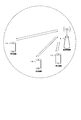
- FIG. 5 is a diagram showing an example of beam forming.
- the plurality of antenna elements are connected to a single transmission unit (TXRU: “Transceiver” unit) 10, controlled in phase by a phase shifter 11 for each antenna element, and transmitted from the antenna element 12 in any direction with respect to the transmission signal.
- TXRU Transmission Unit
- the beam can be directed.
- TXRU may be defined as an antenna port, and only the antenna port may be defined in the terminal device 1. Since the directivity can be directed in an arbitrary direction by controlling the phase shifter 11, the base station apparatus 3 can communicate with the terminal apparatus 1 using a beam having a high gain.
- the terminal device 3 performs measurement in the RRC layer (for example, RRM measurement) in order to measure the quality of the radio link. In addition, the terminal device 3 performs CSI measurement in the physical layer. The terminal device 3 transmits a measurement report in the RRC layer in the RRC layer, and transmits a CSI report in the physical layer in the physical layer.
- RRC layer for example, RRM measurement
- CSI measurement in the physical layer.
- the terminal device 3 transmits a measurement report in the RRC layer in the RRC layer, and transmits a CSI report in the physical layer in the physical layer.
- the CSI report reports the CSI measured by the terminal device 1 to the base station device 3.
- the base station apparatus 3 sets one or more CSI reporting settings (CSI reporting setting (s)) for the terminal apparatus 1.
- the CSI report settings may include the following settings: ⁇ Operation in time direction (transmission method) ⁇ Granularity in frequency domain ⁇ CSI type
- the operation in the time direction may indicate a reference signal transmission method such as aperiodic (may be referred to as “Aperiodic” or “one-shot”), semi-persistent, or periodic.
- aperiodic may be referred to as “Aperiodic” or “one-shot”
- semi-persistent or periodic.
- the granularity in the frequency domain may be, for example, the granularity when calculating PMI and CQI.
- one wideband PMI or wideband CQI may be indicated for all resource blocks included in the bandwidth to be measured.
- the number of resource blocks (number of resource blocks in a partial band and / or resource block group) for measuring subband and / or partial band PMI and / or subband and / or partial band CQI that are narrower than in the band to be measured is shown. Good.
- the CSI type may indicate a CSI type such as which one or a plurality of CSIs to be reported among CQI / PMI / RI / CRI as CSI to be reported. Also, as CSI type, CSI (Type 1) including PMI expressed in codebook is fed back, like analog feedback, higher granularity codebook and / or channel matrix and / or channel covariance matrix CSI type such as extended CSI (type 2) may be indicated.
- CSI (Type 1) including PMI expressed in codebook is fed back, like analog feedback, higher granularity codebook and / or channel matrix and / or channel covariance matrix CSI type such as extended CSI (type 2) may be indicated.
- RS eg, CSI-RS
- the base station apparatus 3 sets one or a plurality of RS settings (RS setting (s)) for the terminal apparatus 1.
- the RS settings may include the following settings. ⁇ Operation in time direction (transmission method) Resources and reference signal types
- the operation in the time direction may indicate a reference signal transmission method such as aperiodic, semi-persistent, or periodic.
- Resource may indicate resource elements and / or OFDM symbols that are mapped in time and / or frequency. Further, in the case of semi-persistent or periodic transmission, a period or a CSI-RS transmission interval (for example, a millisecond unit, a slot unit, or an OFDM symbol unit) may be indicated.
- the CSI-RS resource may be indicated by an index (or identity) to which these pieces of information are mapped.
- period of the reference signal, the subframe offset, and / or the slot offset that are potentially transmitted in any of periodic, semi-persistent, and aperiodic may be included in any of the above RS settings.
- the type of reference signal may indicate, for example, whether a reference signal other than CSI-RS (for example, DMRS) is used as a reference signal for CSI measurement.
- CSI-RS for example, DMRS
- this setting may not be included when only the CSI-RS is a reference signal for CSI measurement.
- the terminal device 1 is used to measure the CSI.
- the base station apparatus 3 sets one or more CSI measurement settings (CSI measurement setting (s)) for the terminal apparatus 1.
- the CSI measurement settings may include the following settings.
- One CSI report setting one setting or index indicating one of one or more CSI reporting settings
- One RS setting one setting of one or a plurality of RS settings or an index indicating it
- the setting of one CSI report may indicate a setting for reporting CSI measured by the CSI measurement setting or an index indicating the CSI report setting in a certain CSI measurement setting.
- One RS setting may indicate a setting of a reference signal used for the CSI measurement setting or an index indicating the setting in a certain CSI setting.
- the CSI report setting may be a setting in which one CSI report setting index is associated with the CSI report setting and the RS setting index included in the CSI report setting.
- the transmission method to be referred to may indicate a transmission method and / or a MIMO method assumed in the CSI measurement in a certain CSI measurement setting.
- the transmission method may be a wireless transmission method such as an OFDM method and / or a DFT-S-OFDM method.
- the MIMO scheme may be a multi-antenna transmission scheme such as transmission diversity, closed loop MIMO, open loop MIMO, quasi-open loop MIMO, for example.
- transmission diversity such as an OFDM method and / or a DFT-S-OFDM method
- closed loop MIMO open loop MIMO
- quasi-open loop MIMO for example.
- it is good also as a transmission system which refers only to either of these.
- the terminal device 1 may be set with a CSI process for measuring CSI.
- one CSI process may be associated with one RS configuration.
- one CSI process may be associated with one CSI reporting configuration.
- the base station apparatus 3 transmits the reference signal based on the RS setting, and the terminal apparatus 1 activates It is recognized (assumed) that a reference signal based on the set RS is transmitted.
- the terminal device 1 receives the reference signal of the time / frequency resource of the reference signal set by the RS setting.
- the period is 5 ms
- the subframe offset (or may be a slot offset) is 0, and the fourth subcarrier in the resource block of the sixth OFDM symbol of each subframe It is assumed that the time / frequency resource in which the CSI-RS is arranged is set.
- a potential resource where the CSI-RS is arranged based on the radio frame number is a subframe ⁇ 0, 5, 10,.
- CSI-RS when CSI-RS is activated in the MAC layer in subframe 3, it recognizes that there is CSI-RS in the radio resource set by the RS setting until it is deactivated in subframe 3 and thereafter.
- the terminal apparatus receives CSI-RS arranged on the fourth subcarrier in the resource block of the fourth OFDM symbol in subframes 5, 10,... After activation of the reference signal.
- the terminal device 1 assumes that the reference signal set by the RS setting is activated. For example, when the reference signal is CSI-RS and CSI-RS is activated in subframe n, transmission of CSI-RS based on the RS setting is performed until the reference signal is deactivated after subframe n.
- the PDSCH is not mapped to the resource element assumed by the terminal device 1 used for the purpose.
- the PDSCH is mapped to the assumed resource element used for the CSI-RS based on the potential RS configuration before or after the deactivation by the terminal apparatus 1 before the subframe n.
- reference signal settings are individually set for each radio link (for terminal apparatus 1, a plurality of CSI processes or a plurality of CSI measurement settings or a plurality of RS settings are set).
- Resource elements to which the PDSCH is mapped may be signaled separately.
- the CSI-RS setting is included in the information related to the PDSCH resource element mapping in DCI, the resource element that is assumed to transmit the CSI-RS when the RS setting reference signal is activated PDSCH is not mapped.
- cooperative communication is an example and is not limited to cooperative communication.
- the activation may be performed based on the RRC setting when the RRC is set and / or when a MAC command is received. For example, when the RRC RS setting includes 'periodic', the corresponding CSI-RS may be activated when the RRC message is received.
- the PDSCH is not mapped to the resource element assumed to transmit the reference signal set by the RS setting.
- a method in which the terminal apparatus 1 sets an RS for CSI reporting from the base station apparatus 3 will be described.
- a corresponding RS setting is specified from an RS setting index included in a CSI measurement setting, and a channel measurement (channel measurement) can be generated based on the RS setting.
- a channel measurement is generated based on the RS setting when the RS setting is set.
- the terminal device 1 is set in the RS setting, and the terminal device 1 is in the RS setting from when the reference signal is activated until it is deactivated.
- the set reference signal may be received based on the RS setting.
- activating the reference signal may mean that the terminal device 1 recognizes that the reference signal is arranged in the resource element based on the RS setting.
- the base station device 3 activates a reference signal in the MAC layer for the terminal device 1, and information for activating the reference signal may be included in the MAC control element or the MAC protocol data unit.
- the terminal device 3 receives at the MAC layer and receives a reference signal based on the RS setting after T (ms).
- T when deactivating, you may instruct
- a reference signal of a resource element based on the RS setting is received for a predetermined or set time. May be. Note that the above T may be included in the RS setting or may be defined in advance. Moreover, when the time until the reference signal is deactivated in the MAC layer is set in advance, it may be included in the RS setting.
- the MAC layer information for activating and / or deactivating the reference signal may include one or more indexes of the RS setting associated with the activated reference signal.
- which RS setting the reference signal is activated may be indicated by a bitmap or may be collectively encoded.
- a bit of each field corresponds to an index of each RS setting, and a reference signal corresponding to a field in which 1 is set is activated. Also, the reference signal corresponding to the field for which 0 is set is deactivated.
- the MAC layer information for activating and / or deactivating the reference signal may include one or more CSI measurement indexes. For example, when one or a plurality of CSI measurement settings are triggered in the MAC layer, which CSI measurement settings to activate CSI measurement may be indicated by a bitmap or may be encoded collectively. The bit of each field corresponds to the index of each CSI measurement, and the CSI measurement corresponding to the field for which 1 is set is activated. Also, the CSI measurement corresponding to the field for which 0 is set is deactivated.
- the terminal device 1 may be triggered to receive a reference signal by DCI. At this time, after the subframe indicated by DCI, the reference signal set by the RS setting may be received based on the RS setting. Further, the terminal device 1 may be instructed to end reception of the reference signal by DCI.
- the DCI may also include one or more CSI measurement indexes set by the CSI measurement settings. Thereby, reception of a reference signal and CSI measurement can be performed efficiently.
- the terminal device 1 may receive a trigger for receiving a reference signal by DCI.
- the reference signal set in the RS setting may be received once or a plurality of times based on the RS setting with the first reference signal resource indicated by the DCI or the first reference signal resource after the indicated subframe.
- the DCI may also include an index of one or more configured CSI measurements. Further, as information included in DCI, which CSI measurement setting is to be triggered may be indicated by a bit map or may be collectively encoded.
- the CSI report setting corresponding to one or an index of the CSI report setting included in the CSI report setting is specified, and the CSI is reported based on the CSI report setting.
- the terminal apparatus 1 may report the CSI periodically based on the CSI setting when the CSI report setting is set.
- the terminal device 1 is set based on the CSI report setting from when the CSI report setting is set until the CSI report is activated until it is deactivated. CSI may be reported.
- activating the CSI report may mean that the terminal device 1 recognizes that the CSI may be reported based on the CSI report setting. Further, in order to activate, the base station device 3 is activated in the MAC layer for the terminal device 1, and the information to be activated may be included in the MAC control element or the MAC protocol data unit. The terminal device 3 receives at the MAC layer, and reports CSI based on the CSI report setting after T (ms). Further, when deactivating the CSI report, the MAC layer may instruct. As for deactivation, after activating the CSI report, the CSI may be reported based on the CSI report setting for a predetermined or set time. Note that the above T may be included in the CSI report setting or may be defined in advance. Moreover, when the time until deactivation in the MAC layer is set in advance, it may be included in the CSI report setting.
- the MAC layer information for activating and / or deactivating the CSI report may include one or more indices of CSI report settings associated with the CSI report to be activated.
- one or more CSI measurement indices may be included as MAC layer information for activating and / or deactivating CSI reports. For example, when one or a plurality of CSI measurement settings are triggered at the MAC layer, which CSI measurement settings are activated may be indicated by a bitmap or may be collectively encoded. The bit of each field corresponds to the index of each CSI report, and the CSI report corresponding to the field for which 1 is set is activated. Also, the CSI report corresponding to the field for which 0 is set is deactivated.
- the terminal device 1 may be requested (triggered) to report CSI by DCI. At this time, CSI may be reported based on the CSI report setting after the subframe indicated by DCI. Further, the terminal device 1 may be instructed to end CSI reporting by DCI. Also, the DCI may include one or more CSI measurement indexes set by CSI measurement settings.
- the terminal device 1 may report a CSI request by DCI.
- CSI may be reported once or a plurality of times based on the CSI report setting in the PUSCH or PUCCH resource for the first CSI report after the subframe indicated by DCI or the subframe indicated by DCI.
- the DCI may also include an index of one or more configured CSI measurements.
- information included in DCI which CSI measurement setting is to be triggered may be indicated by a bit map or may be collectively encoded. Thereby, CSI measurement and CSI report can be performed efficiently.
- One or a plurality of CSI processes can be set for the terminal device 3.
- the CSI process is used as an identity for CSI measurement and CSI reporting regarding the radio link with each base station apparatus 3.
- An ID may be used. However, it is not limited to cooperative communication with a plurality of base station devices 3.
- a CSI process may be associated with one CSI measurement configuration.
- a plurality of CSI measurement settings may be associated with one CSI process.
- the CSI-RS resource setting and the CSI process may be associated.
- IM settings and CSI processes may be associated.
- “CSI measurement setting” may be rephrased as “CSI process”.
- CSI report settings three CSI report settings (CSI report settings C1, C2, and C3) are set, and two RS settings (RS settings R1 and R2) are set.
- CSI report settings C1, C2, and C3 and RS settings R1 and R2 are set as follows.
- -CSI report setting C1 ⁇ Operation in time direction: Semi-persistent ⁇ Frequency domain granularity: Wide band ⁇ CSI type: CQI -CSI report setting C2: ⁇ Operation in time direction: non-periodic ⁇ Granularity in frequency domain: wideband ⁇ CSI type: RI, CQI -CSI report setting C3: ⁇ Operation in time direction: non-periodic ⁇ Granularity in frequency domain: subband (4 resource blocks) CSI type: RI, CQI, PMI, CRI
- ⁇ RS setting R1 ⁇ Operation in time direction: Semi-persistent ⁇ Resource: CSI-RS setting # 1 Reference signal type: CSI-RS RS setting R2: ⁇ Operation in time direction: non-periodic ⁇ Resource: CSI-RS setting # 2 Reference signal type: CSI-RS
- each CSI measurement setting includes the following CSI report setting, RS setting, and reference transmission method.
- -CSI measurement setting M1 ⁇ CSI report setting C1 ⁇ RS setting R1 -Referenced transmission method: transmission diversity-CSI measurement setting M2: ⁇ CSI report setting C2 ⁇ RS setting R1 Referenced transmission method: open loop MIMO -CSI measurement setting M3: ⁇ CSI report setting C3 ⁇ RS setting R2 Referenced transmission method: closed loop MIMO
- the base station apparatus 3 when performing CSI reporting corresponding to the CSI measurement settings M1 and M2, uses the MAC CE or MAC PDU of the MAC layer, or DCI in the physical layer, and CSI corresponding to the CSI measurement settings M1 and M2.
- the terminal device 1 performs CSI measurement corresponding to the CSI measurement settings M1 and M2, and performs CSI reporting.
- RS setting R1 of CSI measurement setting M1 activates semi-persistent transmission in the MAC layer.
- the base station apparatus 3 includes an index associated with the setting of R1 and / or M1 in the information instructing activation.
- the terminal device 1 recognizes the CSI-RS resources based on the time and / or frequency and / or code (orthogonal code, M-sequence, cyclic shift, etc.) of the CSI-RS setting # 1 based on the index.
- CSI is measured until activated.
- the base station apparatus 3 requests the terminal apparatus 1 to report CSI report setting C1 in order to perform CSI reporting corresponding to CSI measurement and CSI measurement setting M1. Since the operation in the time domain of the CSI report setting C1 is semi-persistent, the CSI report is activated by the MAC layer of the base station apparatus 3. The terminal device 1 reports CSI using the resource for CSI reporting until it is deactivated.
- the terminal device 1 may report an index associated with CSI and CSI measurement setting M1 and / or CSI report setting C1 together with CSI at the time of CSI reporting. This index may be defined as one of the CSIs.
- the base station apparatus 3 may perform CSI measurement by activating the reference signal of the RS setting R1.
- CSI reporting configuration C2 is relevant.
- the CSI report is requested (requested) by DCI, and the terminal device 1 receives the CSI report request from the base station device 3 by DCI.
- CSI is reported using CSI reporting resources.
- the resource for CSI reporting may be a PUSCH resource scheduled by the base station apparatus 3.
- the terminal device 1 may report the CSI and the index associated with the CSI measurement setting M2 or the CSI report setting C2 together with the CSI at the time of CSI reporting. This index may be defined as one of the CSIs.
- the reference signal when a plurality of CSI measurement settings are set in the terminal device 1, one or a plurality of pieces of information instructing one activation is provided for the reference signal based on the RS setting activated and / or deactivated in the MAC layer.
- the reference signal may be activated and / or deactivated.
- one piece of information for instructing one activation is set for the participation CSI report based on the CSI report setting activated and / or deactivated in the MAC layer. Or multiple CSI reports may be activated and / or deactivated.
- a reference signal associated with one or a plurality of RS settings is transmitted in one DCI with respect to transmission of a reference signal triggered in the physical layer. Also good.
- a CSI report related to one or a plurality of CSI report settings may be requested in one DCI for a CSI report triggered in the physical layer.
- An interference measurement resource indicates a resource for measuring interference in the case of downlink.
- the base station apparatus 3 sets one or more IM settings (IM setting (s)) for the terminal apparatus 1.
- the interference resource settings may include the following settings. ⁇ Operation in time direction (transmission method) Reference signal type
- the operation in the time direction may indicate a reference signal transmission method such as aperiodic, semi-persistent, or periodic.
- the resource may indicate a resource element and / or an OFDM symbol that are used as interference measurement resources in time and / or frequency. Further, in the case of semi-persistent or periodic transmission, a period or a CSI-IM transmission interval (for example, a millisecond unit, a slot unit, or an OFDM symbol unit) may be indicated. Note that the CSI-IM resource may be indicated by an index (or identity) to which these pieces of information are mapped.
- period, subframe offset, and / or slot offset of the reference signal that is potentially transmitted in any of periodic, semi-persistent, and non-period may be included in any of the above IM settings.
- the type of the reference signal may indicate, for example, whether interference measurement resources other than CSI-IM (for example, NZP CI-RS resource) are used as reference signals for CSI measurement.
- interference measurement resources other than CSI-IM for example, NZP CI-RS resource
- this setting may not be included.
- the IM setting may be included in the RS setting or may be defined separately from the RS setting.
- the interference resource configuration may be included in the CSI measurement configuration as follows.
- One CSI report setting one setting or index indicating one of one or more CSI reporting settings
- One RS setting one setting of one or a plurality of RS settings or an index indicating it
- One IM setting one setting or one index of one or more IM settings)
- the activation of reception of the reference signal based on the RS setting and / or the activation of the interference resource based on the IM setting may be performed in different subframes or slots, or in the same subframe or slot with one information. It may be done.
- the CSI report setting and the RS setting may be set by RRC (upper layer) or may be set in advance by specifications.
- the terminal device 1 recognizes that the reference signal is transmitted based on the RS setting R1. At this time, the CSI report according to the CSI report setting has not yet been activated or triggered.
- CSI report setting C1 is triggered by DCI in subframe n + X (X is a positive integer greater than or equal to 0)
- CSI measurement setting M1 is assumed from the combination of RS setting R1 and CSI report setting C1 as CSI measurement setting M1.
- the terminal device 1 performs channel measurement and CSI report based on the channel measurement configuration associated when the reference signal associated with the RS configuration is activated and triggered and the CSI configuration is activated or triggered. You can go.
- the terminal apparatus 1 recognizes that the CSI report based on the CSI report setting C1 can be performed.
- RS by RS setting has not yet been activated or triggered.
- the CSI measurement setting M1 is assumed from the combination of the RS setting R1 and the CSI report setting C1.
- CSI measurement and CSI reporting are performed based on the CSI measurement setting M1 and the CSI report setting C1. In this case, the activation of CSI measurement may not be defined.
- the terminal device 1 performs channel measurement and CSI report based on the channel measurement configuration associated when the reference signal associated with the RS configuration is activated and triggered and the CSI configuration is activated or triggered. You can go.
- the terminal device 1 when the CSI report associated with the CSI report setting M1 is activated in the subframe n, the terminal device 1 recognizes that it is in a state where CSI measurement based on the CSI measurement setting M1 can be performed. At this time, the CSI report based on the CSI report setting C1 associated with the CSI measurement setting M1 and the reference signal based on the RS setting R1 are activated. The terminal device 1 performs CSI measurement and CSI reporting based on these settings. In this case, the activation of the reference signal based on the RS setting R1 and the activation of the CSI report based on the CSI report setting C1 may not be defined.
- the operation in the time domain of the RS setting R1 is “semi-persistent” and the CSI report setting is “non-periodic”
- the CSI measurement based on the CSI measurement setting M1 is activated.
- a method may be applied in which a reference signal based on the RS setting R1 is activated and the terminal apparatus 1 receives a trigger requesting a CSI report by DCI while the reference signal is activated.
- One aspect of this embodiment may be operated in carrier aggregation or dual connectivity with a radio access technology (RAT: “Radio” Access “Technology”) such as LTE or LTE-A / LTE-A Pro.
- RAT Radio Access “Technology”
- some or all cells or cell groups, carriers or carrier groups for example, primary cell (PCell: Primary Cell), secondary cell (SCell: Secondary Cell), primary secondary cell (PSCell), MCG (Master Cell Group) ), SCG (Secondary Cell Group), etc.
- PCell Primary Cell
- SCell Secondary Cell
- PSCell primary secondary cell
- MCG Master Cell Group
- SCG Secondary Cell Group
- CP-OFDM is applied as the downlink radio transmission scheme
- SC-FDM CP DFTS-OFDM
- FIG. 6 is a schematic block diagram showing the configuration of the terminal device 1 of the present embodiment.
- the terminal device 1 includes an upper layer processing unit 101, a control unit 103, a receiving unit 105, a transmitting unit 107, and a transmission / reception antenna 109.
- the upper layer processing unit 101 includes a radio resource control unit 1011, a scheduling information interpretation unit 1013, and a channel state information (CSI) report control unit 1015.
- the reception unit 105 includes a decoding unit 1051, a demodulation unit 1053, a demultiplexing unit 1055, a wireless reception unit 1057, and a measurement unit 1059.
- the transmission unit 107 includes an encoding unit 1071, a modulation unit 1073, a multiplexing unit 1075, a radio transmission unit 1077, and an uplink reference signal generation unit 1079.
- the upper layer processing unit 101 outputs uplink data (transport block) generated by a user operation or the like to the transmission unit 107.
- the upper layer processing unit 101 includes a medium access control (MAC: Medium Access Control) layer, a packet data integration protocol (Packet Data Convergence Protocol: PDCP) layer, a radio link control (Radio Link Control: RLC) layer, and radio resource control. Process the (Radio Resource Control: RRC) layer.
- MAC Medium Access Control
- PDCP Packet Data Convergence Protocol
- RLC Radio Link Control
- RRC Radio Resource Control
- the radio resource control unit 1011 included in the upper layer processing unit 101 manages various setting information of the own device. Also, the radio resource control unit 1011 generates information arranged in each uplink channel and outputs the information to the transmission unit 107.
- the scheduling information interpretation unit 1013 included in the higher layer processing unit 101 interprets the DCI (scheduling information) received via the reception unit 105, and based on the interpretation result of the DCI, the reception unit 105 and the transmission unit 107 In order to perform control, control information is generated and output to the control unit 103.
- DCI scheduling information
- the CSI report control unit 1015 instructs the measurement unit 1059 to derive channel state information (RI / PMI / CQI / CRI) related to the CSI reference resource.
- the CSI report control unit 1015 instructs the transmission unit 107 to transmit RI / PMI / CQI / CRI.
- the CSI report control unit 1015 sets a setting used when the measurement unit 1059 calculates the CQI.
- the control unit 103 generates a control signal for controlling the reception unit 105 and the transmission unit 107 based on the control information from the higher layer processing unit 101.
- the control unit 103 outputs the generated control signal to the reception unit 105 and the transmission unit 107 to control the reception unit 105 and the transmission unit 107.
- the receiving unit 105 separates, demodulates, and decodes the received signal received from the base station apparatus 3 via the transmission / reception antenna 109 according to the control signal input from the control unit 103, and sends the decoded information to the upper layer processing unit 101. Output.
- the radio reception unit 1057 converts the downlink signal received via the transmission / reception antenna 109 into an intermediate frequency (down-conversion: down covert), removes unnecessary frequency components, and maintains the signal level appropriately. Then, the amplification level is controlled, quadrature demodulation is performed based on the in-phase component and the quadrature component of the received signal, and the quadrature demodulated analog signal is converted into a digital signal.
- the radio reception unit 1057 removes a portion corresponding to a guard interval (Guard Interval: GI) from the converted digital signal, and performs a fast Fourier transform (FFT Fourier Transform: FFT) on the signal from which the guard interval has been removed. Extract the region signal.
- GI Guard Interval
- FFT fast Fourier transform
- the demultiplexing unit 1055 separates the extracted signals into downlink PCCH, PSCH, and downlink reference signals. Further, demultiplexing section 1055 performs PCCH and PSCH propagation path compensation based on the propagation path estimation value input from measurement section 1059. Also, the demultiplexing unit 1055 outputs the separated downlink reference signal to the measurement unit 1059.
- Demodulation section 1053 demodulates the downlink PCCH and outputs the result to decoding section 1051.
- Decoding section 1051 attempts to decode the PCCH, and when decoding is successful, outputs the decoded downlink control information and the RNTI corresponding to the downlink control information to higher layer processing section 101.
- the demodulating unit 1053 demodulates the PSCH with the modulation scheme notified by a downlink grant such as QPSK (Quadrature Phase Shift Keying), 16 QAM (Quadrature Amplitude Modulation), 64 QAM, 256 QAM, and the like, and outputs the result to the decoding unit 1051 To do.
- Decoding section 1051 performs decoding based on the information related to transmission or original coding rate notified by downlink control information, and outputs the decoded downlink data (transport block) to higher layer processing section 101.
- the measurement unit 1059 performs downlink path loss measurement, channel measurement, and / or interference measurement from the downlink reference signal input from the demultiplexing unit 1055.
- the measurement unit 1059 outputs the CSI calculated based on the measurement result and the measurement result to the upper layer processing unit 101. Also, measurement section 1059 calculates an estimated value of the downlink propagation path from the downlink reference signal, and outputs it to demultiplexing section 1055.
- the transmission unit 107 generates an uplink reference signal according to the control signal input from the control unit 103, encodes and modulates the uplink data (transport block) input from the higher layer processing unit 101, PUCCH, The PUSCH and the generated uplink reference signal are multiplexed and transmitted to the base station apparatus 3 via the transmission / reception antenna 109.
- the encoding unit 1071 encodes the uplink control information and the uplink data input from the higher layer processing unit 101.
- the modulation unit 1073 modulates the coded bits input from the coding unit 1071 with a modulation scheme such as BPSK, QPSK, 16QAM, 64QAM, and 256QAM.
- the uplink reference signal generation unit 1079 is a physical cell identifier for identifying the base station device 3 (referred to as physical cell ⁇ ⁇ identity: ⁇ ⁇ ⁇ PCI, Cell ⁇ ID, etc.), a bandwidth for arranging the uplink reference signal, and an uplink grant.
- a sequence determined by a predetermined rule is generated based on the notified cyclic shift, the value of a parameter for generating the DMRS sequence, and the like.
- the multiplexing unit 1075 determines the number of spatially multiplexed PUSCH layers based on information used for PUSCH scheduling, and uses MIMO spatial multiplexing (MIMO SM: (Multiple Input Multiple Output Spatial Multiplexing) on the same PUSCH.
- MIMO SM Multiple Input Multiple Output Spatial Multiplexing
- a plurality of uplink data to be transmitted is mapped to a plurality of layers, and precoding is performed on the layers.
- the multiplexing unit 1075 performs discrete Fourier transform (Discrete-Fourier-Transform: DFT) on the modulation symbols of the PSCH according to the control signal input from the control unit 103. Further, multiplexing section 1075 multiplexes the PCCH and PSCH signals and the generated uplink reference signal for each transmission antenna port. That is, multiplexing section 1075 arranges the PCCH and PSCH signals and the generated uplink reference signal in the resource element for each transmission antenna port.
- DFT discrete Fourier transform
- the radio transmitter 1077 performs inverse fast Fourier transform (Inverse Fast FourierTransform: IFFT) on the multiplexed signal, performs SC-FDM modulation, and adds a guard interval to the SC-FDM-modulated SC-FDM symbol.
- IFFT inverse Fast Fourier Transform
- Generate baseband digital signal convert baseband digital signal to analog signal, generate in-phase and quadrature components of intermediate frequency from analog signal, remove excess frequency component for intermediate frequency band, intermediate
- the frequency signal is converted into a high-frequency signal (up-conversion: up convert), the excess frequency component is removed, the power is amplified, and output to the transmission / reception antenna 109 for transmission.
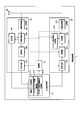
- FIG. 7 is a schematic block diagram showing the configuration of the base station apparatus 3 of the present embodiment.
- the base station apparatus 3 includes an upper layer processing unit 301, a control unit 303, a reception unit 305, a transmission unit 307, and a transmission / reception antenna 309.
- the upper layer processing unit 301 includes a radio resource control unit 3011, a scheduling unit 3013, and a CSI report control unit 3015.
- the reception unit 305 includes a decoding unit 3051, a demodulation unit 3053, a demultiplexing unit 3055, a wireless reception unit 3057, and a measurement unit 3059.
- the transmission unit 307 includes an encoding unit 3071, a modulation unit 3073, a multiplexing unit 3075, a radio transmission unit 3077, and a downlink reference signal generation unit 3079.
- the upper layer processing unit 301 includes a medium access control (MAC: Medium Access Control) layer, a packet data integration protocol (Packet Data Convergence Protocol: PDCP) layer, a radio link control (Radio Link Control: RLC) layer, a radio resource control (Radio). Resource (Control: RRC) layer processing. Further, the upper layer processing unit 301 generates control information for controlling the reception unit 305 and the transmission unit 307 and outputs the control information to the control unit 303.
- MAC Medium Access Control
- PDCP Packet Data Convergence Protocol
- RLC Radio Link Control
- Radio Radio Resource
- the radio resource control unit 3011 included in the upper layer processing unit 301 generates downlink data (transport block), system information, RRC message, MAC CE (Control element), etc. arranged in the downlink PSCH, or higher layer. Obtained from the node and output to the transmission unit 307.
- the radio resource control unit 3011 manages various setting information of each terminal device 1.
- the scheduling unit 3013 included in the upper layer processing unit 301 uses the received CSI and the channel estimation value, the channel quality, and the like to which the physical channel (PSCH) is allocated based on the channel estimation value and the channel quality. PSCH) transmission coding rate, modulation scheme, transmission power, and the like are determined.
- the scheduling unit 3013 generates control information for controlling the reception unit 305 and the transmission unit 307 based on the scheduling result, and outputs the control information to the control unit 303.
- the scheduling unit 3013 generates information (for example, DCI (format)) used for physical channel (PSCH) scheduling based on the scheduling result.
- the CSI report control unit 3015 provided in the higher layer processing unit 301 controls the CSI report of the terminal device 1.
- the CSI report control unit 3015 transmits, to the terminal device 1 via the transmission unit 307, information indicating various settings assumed for the terminal device 1 to derive RI / PMI / CQI in the CSI reference resource.
- the control unit 303 generates a control signal for controlling the reception unit 305 and the transmission unit 307 based on the control information from the higher layer processing unit 301.
- the control unit 303 outputs the generated control signal to the reception unit 305 and the transmission unit 307 and controls the reception unit 305 and the transmission unit 307.
- the receiving unit 305 separates, demodulates and decodes the received signal received from the terminal device 1 via the transmission / reception antenna 309 according to the control signal input from the control unit 303, and outputs the decoded information to the higher layer processing unit 301.
- the radio reception unit 3057 converts an uplink signal received via the transmission / reception antenna 309 into an intermediate frequency (down-conversion: down covert), removes unnecessary frequency components, and appropriately maintains the signal level. In this way, the amplification level is controlled, and based on the in-phase and quadrature components of the received signal, quadrature demodulation is performed, and the quadrature demodulated analog signal is converted into a digital signal.
- the wireless receiver 3057 removes a portion corresponding to a guard interval (Guard Interval: GI) from the converted digital signal.
- the radio reception unit 3057 performs fast Fourier transform (FFT) on the signal from which the guard interval is removed, extracts a frequency domain signal, and outputs the signal to the demultiplexing unit 3055.
- FFT fast Fourier transform
- the demultiplexing unit 1055 demultiplexes the signal input from the radio receiving unit 3057 into signals such as PCCH, PSCH, and uplink reference signal. This separation is performed based on radio resource allocation information included in the uplink grant that is determined in advance by the radio resource control unit 3011 by the base station device 3 and notified to each terminal device 1. Further, the demultiplexing unit 3055 compensates the propagation paths of the PCCH and the PSCH from the propagation path estimation value input from the measurement unit 3059. Also, the demultiplexing unit 3055 outputs the separated uplink reference signal to the measurement unit 3059.
- the demodulator 3053 performs inverse discrete Fourier transform (Inverse Discrete Fourier Transform: IDFT) to obtain modulation symbols, and BPSK (Binary Shift Keying), QPSK, 16QAM,
- IDFT Inverse Discrete Fourier Transform
- BPSK Binary Shift Keying
- QPSK 16QAM
- the received signal is demodulated using a predetermined modulation scheme such as 64QAM, 256QAM or the like, or a modulation scheme that the device itself has previously notified to each terminal device 1 with an uplink grant.
- the demodulator 3053 uses the MIMO SM based on the number of spatially multiplexed sequences notified in advance to each terminal device 1 using an uplink grant and information indicating precoding performed on the sequences. A plurality of uplink data modulation symbols transmitted on the PSCH are separated.
- the decoding unit 3051 transmits the demodulated encoded bits of the PCCH and the PSCH according to a predetermined encoding method, a predetermined transmission method, or a transmission or original signal that the own device has previously notified the terminal device 1 using an uplink grant. Decoding is performed at the coding rate, and the decoded uplink data and uplink control information are output to the upper layer processing section 101. When the PSCH is retransmitted, the decoding unit 3051 performs decoding using the encoded bits held in the HARQ buffer input from the higher layer processing unit 301 and the demodulated encoded bits.
- the measurement unit 309 measures the channel estimation value, channel quality, and the like from the uplink reference signal input from the demultiplexing unit 3055 and outputs the measured values to the demultiplexing unit 3055 and the upper layer processing unit 301.
- the transmission unit 307 generates a downlink reference signal according to the control signal input from the control unit 303, encodes and modulates downlink control information and downlink data input from the higher layer processing unit 301, and performs PCCH , PSCH, and downlink reference signal are multiplexed or transmitted with different radio resources to the terminal device 1 via the transmission / reception antenna 309.
- the encoding unit 3071 encodes downlink control information and downlink data input from the higher layer processing unit 301.
- the modulation unit 3073 modulates the coded bits input from the coding unit 3071 using a modulation scheme such as BPSK, QPSK, 16QAM, 64QAM, and 256QAM.
- the downlink reference signal generation unit 3079 generates a known sequence as a downlink reference signal, which is obtained by a predetermined rule based on a physical cell identifier (PCI) for identifying the base station apparatus 3 and the like. To do.
- PCI physical cell identifier
- the multiplexing unit 3075 maps one or more downlink data transmitted on one PSCH to one or more layers according to the number of spatially multiplexed PSCH layers, and the one or more layers Precoding the layer.
- the multiplexing unit 375 multiplexes the downlink physical channel signal and the downlink reference signal for each transmission antenna port.
- the multiplexing unit 375 arranges the downlink physical channel signal and the downlink reference signal in the resource element for each transmission antenna port.
- the wireless transmission unit 3077 performs inverse fast Fourier transform (Inverse Fast Fourier Transform: IFFT) on the multiplexed modulation symbols and the like, performs modulation in the OFDM scheme, adds a guard interval to the OFDM symbol that has been OFDM-modulated, and baseband
- IFFT inverse Fast Fourier Transform
- the baseband digital signal is converted to an analog signal, the in-phase and quadrature components of the intermediate frequency are generated from the analog signal, the extra frequency components for the intermediate frequency band are removed, and the intermediate-frequency signal is generated. Is converted to a high-frequency signal (up-conversion: up convert), an extra frequency component is removed, power is amplified, and output to the transmission / reception antenna 309 for transmission.
- the terminal device 1 is a terminal device that communicates with a base station device, and includes first information including one or more first settings.
- a receiving unit that receives, receives second information including one or more second settings, receives third information including one or more third settings, and receives fourth information
- a channel state measurement unit that measures channel state information, and a transmission unit that reports the channel state information, wherein the first setting is a setting for one or more reports of the channel state information
- the first setting for the one or more reports includes a first index
- the second setting includes one or more reference signals for measuring the channel state information The one or more references.
- Each of the signal related settings includes one second index
- the third setting includes one index of the first index, one index of the second index, and one first index.
- the fourth information includes information indicating one or more of the third indexes.
- the one or more third settings are specified based on one or more of the third indexes included in the fourth information, and the specified One or more first settings and one or more second settings are identified based on one or more of the third settings, and the identified one or more first settings And transmitting one or more channel state information reports based on the one or more second settings.
- the one or more channel state information reports are transmitted by a procedure in a physical layer.
- the transmitting unit transmits the channel state information including one of the third indexes.
- the receiving unit further receives fifth information including one or more fourth settings, receives sixth information, and the fourth settings are , Settings for one or more interference measurement resources for measuring the channel state information, each of the settings for the one or more interference measurement resources includes a fourth index, and The setting further includes one index of the fourth index.
- the base station apparatus 3 is a base station apparatus that communicates with a terminal apparatus, and transmits first information including one or more first settings. Or a transmitter that transmits second information including a plurality of second settings, transmits third information including one or more third settings, and transmits fourth information; and channel state information
- a channel receiving unit for receiving wherein the first setting is a setting for one or more reports of the channel state information, and each of the settings for the one or more reports is One first index, and the second setting is a setting related to one or more reference signals for measuring the channel state information, and each of the setting related to the one or more reference signals Is one second index
- the third setting includes one index of the first index, one index of the second index, and one third index, and the fourth information is , Including information indicating one or more of the third indexes.
- one or more channels based on one or more third settings based on one or more third indexes included in the fourth information Receive status information reports.
- the one or more channel state information reports are received by a procedure in a physical layer.
- the channel state information includes one of the third indexes.
- the transmission unit further transmits fifth information including one or more fourth settings and sixth information, and the fourth settings are Settings for one or more interference measurement resources for measuring channel state information, each of the settings for the one or more interference measurement resources includes a third index, and the third setting Further includes one index of the fourth index.
- a communication method is a communication method of a terminal device that communicates with a base station device, and receives first information including one or more first settings, Receiving second information including one or more second settings, receiving third information including one or more third settings, receiving fourth information, and measuring channel state information And reporting the channel state information, wherein the first setting is a setting for one or more reports of the channel state information, and each of the settings for the one or more reports is: Including a first index, wherein the second setting is a setting for one or more reference signals for measuring the channel state information, and each of the setting for the one or more reference signals is One second index And the third setting includes one index of the first index, one index of the second index, and one third index, and the fourth information is , Including information indicating one or more of the third indexes.
- a communication method is a communication method of a base station device that communicates with a terminal device, and transmits first information including one or more first settings, Transmitting second information including one or more second settings, transmitting third information including one or more third settings, transmitting fourth information, receiving channel state information
- the first setting is a setting for one or more reports of the channel state information, and each of the settings for the one or more reports includes a first index.
- the second setting is a setting related to one or more reference signals for measuring the channel state information, and each of the setting related to the one or more reference signals has one second index.
- the third setting includes the One index of one index, one index of the second index, and one third index, wherein the fourth information is one or more of the third index Contains information indicating.
- An integrated circuit is an integrated circuit mounted on a terminal device that communicates with a base station device, and receives first information including one or more first settings.
- Channel state measuring means for measuring channel state information, and transmitting means for reporting the channel state information, wherein the first setting is a setting for one or more reports of the channel state information.
- each of the settings for the one or more reports includes a first index
- the second setting relates to one or more reference signals for measuring the channel state information Setting
- Each of the settings related to the plurality of reference signals includes one second index
- the third setting includes one index of the first index, one index of the second index, and One third index
- the fourth information includes information indicating one or more of the third indexes.
- An integrated circuit is an integrated circuit mounted on a base station device that communicates with a terminal device, and transmits first information including one or more first settings.
- Channel receiving means for receiving channel state information wherein the first setting is a setting for one or more reports of the channel state information, and for the one or more reports
- Each of the settings includes one first index
- the second setting is a setting related to one or more reference signals for measuring the channel state information, and the one or more reference signals
- Each setting for is one Including a second index
- the third setting includes one index of the first index, one index of the second index, and one third index
- the fourth information includes information indicating one or more of the third indexes.
- a terminal device is a terminal device that communicates with a base station device, receives first information including one or more first settings, and receives one or more first devices.
- the state measurement unit and the first setting are settings for one or more reports of the channel state information, and each of the first settings includes a first index, 2 settings are settings for one or more reference signals for measuring the channel state information, each of the second settings includes one second index, and the third setting is , One of the first indexes Wherein the index, and one index of said second index, and one third index, wherein the fourth information includes information indicative of one or more of the third index.
- the one or more channel state information reports are transmitted by a procedure in a physical layer.
- the base station apparatus is a base station apparatus that communicates with a terminal apparatus, transmits first information including one or more first settings, and includes one or more Transmitting second information including a plurality of second settings, transmitting third information including one or more third settings, and transmitting fourth information; and channel state information.
- the second setting is a setting for one or more reference signals for measuring the channel state information, and each of the second settings includes a second index
- the third setting is the first index One index, one index of the second index, and one third index
- the fourth information includes information indicating one or more of the third indexes.
- the one or more channel state information reports are received by a procedure in the physical layer.
- the communication method in 1 aspect of this invention is a communication method of the terminal device which communicates with a base station apparatus, receives the 1st information containing 1 or one 1st setting, 1 Receiving second information including one or more second settings, receiving third information including one or more third settings, receiving fourth information, and measuring channel state information
- the first setting is a setting for one or more reports of the channel state information
- each of the first settings includes one first index
- the second setting Is a setting for one or more reference signals for measuring the channel state information
- each of the second settings includes a second index
- the third setting is One of the indexes
- Serial includes a single index of the second index, and one third index
- the fourth information includes information indicative of one or more of the third index.
- a communication method is a communication method of a base station device that communicates with a terminal device, and transmits first information including one or more first settings, Transmitting second information including one or more second settings, transmitting third information including one or more third settings, transmitting fourth information, receiving channel state information
- the first setting is a setting for one or more reports of the channel state information
- each of the first settings includes one first index
- the second setting Is a setting for one or more reference signals for measuring the channel state information
- each of the second settings includes a second index
- the third setting is One of the indexes, and Serial includes a single index of the second index, and one third index, wherein the fourth information includes information indicative of one or more of the third index.
- the integrated circuit is an integrated circuit mounted on a terminal device that communicates with the base station device, and receives first information including one or more first settings.
- Channel state measuring means for measuring channel state information, and transmitting means for reporting the channel state information, wherein the first setting is a setting for one or more reports of the channel state information.
- each of the first settings includes a first index
- the second setting is a setting for one or more reference signals for measuring the channel state information
- Each of the two settings is one Including a second index
- the third setting includes one index of the first index, one index of the second index, and one third index
- the fourth information includes information indicating one or more of the third indexes.
- An integrated circuit is an integrated circuit mounted on a base station device that communicates with a terminal device, and transmits first information including one or more first settings.
- the second setting is a setting for one or more reference signals for measuring the channel state information, and each of the second settings is one second Including the index
- the third setting is One index of the first index, one index of the second index, and one third index
- the fourth information is one of the third indexes. Or, information including plural information is included.
- a program that operates on an apparatus according to one aspect of the present invention is a program that controls a central processing unit (CPU) or the like to function a computer so as to realize the function of the embodiment according to one aspect of the present invention. Also good.
- the program or information handled by the program is temporarily stored in a volatile memory such as a Random Access Memory (RAM), a non-volatile memory such as a flash memory, a Hard Disk Drive (HDD), or other storage system.
- RAM Random Access Memory
- HDD Hard Disk Drive
- a program for realizing the functions of the embodiments according to one aspect of the present invention may be recorded on a computer-readable recording medium. You may implement
- the “computer system” here is a computer system built in the apparatus, and includes hardware such as an operating system and peripheral devices.
- the “computer-readable recording medium” refers to a semiconductor recording medium, an optical recording medium, a magnetic recording medium, a medium that dynamically holds a program for a short time, or other recording medium that can be read by a computer. Also good.
- each functional block or various features of the apparatus used in the above-described embodiments can be implemented or executed by an electric circuit, for example, an integrated circuit or a plurality of integrated circuits.
- Electrical circuits designed to perform the functions described herein can be general purpose processors, digital signal processors (DSPs), application specific integrated circuits (ASICs), field programmable gate arrays (FPGAs), or others Programmable logic devices, discrete gate or transistor logic, discrete hardware components, or a combination thereof.
- a general purpose processor may be a microprocessor or a conventional processor, controller, microcontroller, or state machine.
- the electric circuit described above may be configured with a digital circuit or an analog circuit.
- one or more aspects of the present invention can use a new integrated circuit based on the technology.
- the present invention is not limited to the above-described embodiment.
- an example of the apparatus has been described.
- the present invention is not limited to this, and a stationary or non-movable electronic device installed indoors or outdoors, such as an AV device, a kitchen device, It can be applied to terminal devices or communication devices such as cleaning / washing equipment, air conditioning equipment, office equipment, vending machines, and other daily life equipment.
- One embodiment of the present invention is used in, for example, a communication system, a communication device (for example, a mobile phone device, a base station device, a wireless LAN device, or a sensor device), an integrated circuit (for example, a communication chip), a program, or the like. be able to.
- a communication device for example, a mobile phone device, a base station device, a wireless LAN device, or a sensor device
- an integrated circuit for example, a communication chip
- a program or the like.
Abstract
The present invention comprises: a reception unit which receives first information containing one or more first settings, second information containing one or more second settings, third information containing one or more third settings, and fourth information; and a channel state measurement unit which measures channel state information, wherein: the first settings are for making one or more reports of the channel state information, and each of the first settings contains a single first index; the second settings pertain to one or more reference signals for measuring the channel state information, and each of the second settings contains a single second index; the third settings contain one of the first indices, one of the second indices, and a single third index; and the fourth information contains information indicating one or more of the third indices.
Description
本発明は、基地局装置、端末装置、通信方法、および、集積回路に関する。
本願は、2016年12月20日に日本に出願された特願2016-246463号について優先権を主張し、その内容をここに援用する。 The present invention relates to a base station device, a terminal device, a communication method, and an integrated circuit.
This application claims priority on Japanese Patent Application No. 2016-246463 filed in Japan on December 20, 2016, the contents of which are incorporated herein by reference.
現在、第5世代のセルラーシステムに向けた無線アクセス方式および無線ネットワーク技術として、第三世代パートナーシッププロジェクト(3GPP: The Third Generation Partnership Project)において、LTE(Long Term Evolution)-Advanced Pro及びNR(New Radio technology)の技術検討及び規格策定が行われている(非特許文献1)。
Currently, the third generation partnership project (3GPP: “The Third Generation Generation Partnership Project”) has developed LTE (Long Term Termination Evolution) -Advanced® Pro and NR (New Radio) as wireless access methods and wireless network technologies for the fifth generation cellular system. technology) and standards are being developed (Non-Patent Document 1).
第5世代のセルラーシステムでは、高速・大容量伝送を実現するeMBB(enhanced Mobile BroadBand)、低遅延・高信頼通信を実現するURLLC(Ultra-Reliable and Low Latency Communication)、IoT(Internet of Things)などマシン型デバイスが多数接続するmMTC(massive Machine Type Communication)の3つがサービスの想定シナリオとして要求されている。
In the fifth generation cellular system, eMBB (enhanced Mobile Broadband) that realizes high-speed and large-capacity transmission, URLLC (Ultra-Reliable and Low Latency Communication) that realizes low-latency and high-reliability communication, IoT (Internet-of-Things), etc. There are three service scenarios that require a large number of machine type devices: mmCTC (massive Machine Type Communication).
NRでは、高い周波数で多数のアンテナエレメントを用いてビームフォーミングゲインによりカバレッジを確保するマッシブMIMO(Multiple-Input Multiple-Output)の技術検討が行われている(非特許文献2、非特許文献3、非特許文献4)。
In NR, massive MIMO (Multiple-Input Multiple-Output) technology that secures coverage by beam forming gain using a large number of antenna elements at high frequencies is being studied (Non-patent Document 2, Non-patent Document 3, Non-patent document 4).
本発明の目的は、上記のような無線通信システムにおいて、基地局装置と端末装置が、効率的に端末装置、基地局装置、通信方法、および、集積回路を提供することを目的とする。
An object of the present invention is to provide a terminal device, a base station device, a communication method, and an integrated circuit in which the base station device and the terminal device efficiently in the wireless communication system as described above.
(1)上記の目的を達成するために、本発明の態様は、以下のような手段を講じた。すなわち、本発明の一態様における端末装置は、基地局装置と通信する端末装置であって、1つまたは複数の第1の設定を含む第1の情報を受信し、1つまたは複数の第2の設定を含む第2の情報を受信し、1つまたは複数の第3の設定を含む第3の情報を受信し、第4の情報を受信する受信部と、チャネル状態情報を測定するチャネル状態測定部と、前記第1の設定は、前記チャネル状態情報の1つまたは複数の報告のための設定であり、前記第1の設定のそれぞれは、1つの第1のインデックスを含み、前記第2の設定は、前記チャネル状態情報を測定するための1つまたは複数の参照信号に関する設定であり、前記第2の設定のそれぞれは、1つの第2のインデックスを含み、前記第3の設定は、前記第1のインデックスのうち1つのインデックスと、前記第2のインデックスのうち1つのインデックスと、1つの第3のインデックスと、を含み、前記第4の情報は、前記第3のインデックスの1つまたは複数を示す情報を含む。
(1) In order to achieve the above object, the aspect of the present invention takes the following measures. That is, the terminal device according to an aspect of the present invention is a terminal device that communicates with a base station device, receives first information including one or more first settings, and receives one or more second information. Receiving the second information including the settings of the first, receiving the third information including the one or more third settings, receiving the fourth information, and the channel state for measuring the channel state information The measurement unit and the first setting are settings for one or more reports of the channel state information, and each of the first settings includes one first index, and the second setting Are the settings for one or more reference signals for measuring the channel state information, each of the second settings includes a second index, and the third setting is: One of the first index Wherein the index, and one index of said second index, and one third index, wherein the fourth information includes information indicative of one or more of the third index.
(2)また、本発明の一態様における端末装置において、前記第4の情報に含まれる1つまたは複数の前記第3のインデックスに基づいて1つまたは複数の第1の設定と1つまたは複数の前記第2の設定を特定し、前記特定された1つまたは複数の第1の設定と1つまたは複数の前記第2の設定に基づいて1つまたは複数のチャネル状態情報報告を送信する。
(2) In the terminal device according to the aspect of the present invention, one or more first settings and one or more based on one or more of the third indexes included in the fourth information. The second setting is identified, and one or more channel state information reports are transmitted based on the identified one or more first settings and the one or more second settings.
(3)また、本発明の一態様における端末装置において、前記1つまたは複数のチャネル状態情報報告は、物理層における手続きで送信される。
(3) Also, in the terminal device according to an aspect of the present invention, the one or more channel state information reports are transmitted by a procedure in the physical layer.
(4)また、本発明の一態様における基地局装置は、端末装置と通信する基地局装置であって、1つまたは複数の第1の設定を含む第1の情報を送信し、1つまたは複数の第2の設定を含む第2の情報を送信し、1つまたは複数の第3の設定を含む第3の情報を送信し、第4の情報を送信する送信部と、チャネル状態情報を受信するチャネル受信部と、を備え、前記第1の設定は、前記チャネル状態情報の1つまたは複数の報告のための設定であり、前記第1の設定のそれぞれは、1つの第1のインデックスを含み、前記第2の設定は、前記チャネル状態情報を測定するための1つまたは複数の参照信号に関する設定であり、前記第2の設定のそれぞれは、1つの第2のインデックスを含み、前記第3の設定は、前記第1のインデックスのうち1つのインデックスと、前記第2のインデックスのうち1つのインデックスと、1つの第3のインデックスと、を含み、前記第4の情報は、前記第3のインデックスの1つまたは複数を示す情報を含む。
(4) Moreover, the base station apparatus in 1 aspect of this invention is a base station apparatus which communicates with a terminal device, Comprising: The 1st information containing 1 or one 1st setting is transmitted, 1 or Transmitting second information including a plurality of second settings, transmitting third information including one or more third settings, and transmitting fourth information; and channel state information. A channel receiver for receiving, wherein the first setting is a setting for one or more reports of the channel state information, and each of the first settings is a first index. And the second setting is a setting for one or more reference signals for measuring the channel state information, and each of the second settings includes a second index, The third setting is for the first index. Each index, one index of the second index, and one third index, and the fourth information includes information indicating one or more of the third indexes. Including.
(5)また、本発明の一態様における基地局装置において、前記第4の情報に含まれる1つまたは複数の前記第3のインデックスに基づいて1つまたは複数の前記第3の設定に基づく1つまたは複数のチャネル状態情報報告を受信する。
(5) Further, in the base station apparatus according to an aspect of the present invention, 1 based on one or more third settings based on one or more third indexes included in the fourth information. Receive one or more channel state information reports.
(6)また、本発明の一態様における基地局装置において、前記1つまたは複数のチャネル状態情報報告は、物理層における手続きで受信される。
(6) In the base station apparatus according to an aspect of the present invention, the one or more channel state information reports are received by a procedure in the physical layer.
(7)また、本発明の一態様における通信方法は、基地局装置と通信する端末装置の通信方法であって、1つまたは複数の第1の設定を含む第1の情報を受信し、1つまたは複数の第2の設定を含む第2の情報を受信し、1つまたは複数の第3の設定を含む第3の情報を受信し、第4の情報を受信し、チャネル状態情報を測定し、前記第1の設定は、前記チャネル状態情報の1つまたは複数の報告のための設定であり、前記第1の設定のそれぞれは、1つの第1のインデックスを含み、前記第2の設定は、前記チャネル状態情報を測定するための1つまたは複数の参照信号に関する設定であり、前記第2の設定のそれぞれは、1つの第2のインデックスを含み、前記第3の設定は、前記第1のインデックスのうち1つのインデックスと、前記第2のインデックスのうち1つのインデックスと、1つの第3のインデックスと、を含み、前記第4の情報は、前記第3のインデックスの1つまたは複数を示す情報を含む。
(7) Moreover, the communication method in 1 aspect of this invention is a communication method of the terminal device which communicates with a base station apparatus, receives the 1st information containing one or more 1st settings, 1 Receiving second information including one or more second settings, receiving third information including one or more third settings, receiving fourth information, and measuring channel state information And the first setting is a setting for one or more reports of the channel state information, and each of the first settings includes one first index, and the second setting Is a setting for one or more reference signals for measuring the channel state information, each of the second settings includes a second index, and the third setting is One index of 1 and previous And one index of the second index includes a one third index, wherein the fourth information includes information indicative of one or more of the third index.
(8)また、本発明の一態様における通信方法は、端末装置と通信する基地局装置の通信方法であって、1つまたは複数の第1の設定を含む第1の情報を送信し、1つまたは複数の第2の設定を含む第2の情報を送信し、1つまたは複数の第3の設定を含む第3の情報を送信し、第4の情報を送信し、チャネル状態情報を受信し、前記第1の設定は、前記チャネル状態情報の1つまたは複数の報告のための設定であり、前記第1の設定のそれぞれは、1つの第1のインデックスを含み、前記第2の設定は、前記チャネル状態情報を測定するための1つまたは複数の参照信号に関する設定であり、前記第2の設定のそれぞれは、1つの第2のインデックスを含み、前記第3の設定は、前記第1のインデックスのうち1つのインデックスと、前記第2のインデックスのうち1つのインデックスと、1つの第3のインデックスと、を含み、前記第4の情報は、前記第3のインデックスの1つまたは複数を示す情報を含む。
(8) Moreover, the communication method in 1 aspect of this invention is a communication method of the base station apparatus which communicates with a terminal device, and transmits the 1st information containing 1 or one 1st setting, 1 Transmitting second information including one or more second settings, transmitting third information including one or more third settings, transmitting fourth information, receiving channel state information And the first setting is a setting for one or more reports of the channel state information, and each of the first settings includes one first index, and the second setting Is a setting for one or more reference signals for measuring the channel state information, each of the second settings includes a second index, and the third setting is One index of 1 and previous And one index of the second index includes a one third index, wherein the fourth information includes information indicative of one or more of the third index.
(9)また、本発明の一態様における集積回路は、基地局装置と通信する端末装置に実装される集積回路であって、1つまたは複数の第1の設定を含む第1の情報を受信し、1つまたは複数の第2の設定を含む第2の情報を受信し、1つまたは複数の第3の設定を含む第3の情報を受信し、第4の情報を受信する受信手段と、チャネル状態情報を測定するチャネル状態測定手段と、前記チャネル状態情報を報告する送信手段と、を備え、前記第1の設定は、前記チャネル状態情報の1つまたは複数の報告のための設定であり、前記第1の設定のそれぞれは、1つの第1のインデックスを含み、前記第2の設定は、前記チャネル状態情報を測定するための1つまたは複数の参照信号に関する設定であり、前記第2の設定のそれぞれは、1つの第2のインデックスを含み、前記第3の設定は、前記第1のインデックスのうち1つのインデックスと、前記第2のインデックスのうち1つのインデックスと、1つの第3のインデックスと、を含み、前記第4の情報は、前記第3のインデックスの1つまたは複数を示す情報を含む。
(9) Moreover, the integrated circuit in 1 aspect of this invention is an integrated circuit mounted in the terminal device which communicates with a base station apparatus, Comprising: The 1st information containing 1 or one 1st setting is received. Receiving means for receiving second information including one or more second settings, receiving third information including one or more third settings, and receiving fourth information; Channel state measuring means for measuring channel state information, and transmitting means for reporting the channel state information, wherein the first setting is a setting for one or more reports of the channel state information. And each of the first settings includes a first index, and the second setting is a setting for one or more reference signals for measuring the channel state information, and Each of the two settings is one The third setting includes one index of the first index, one index of the second index, and one third index, and The information of 4 includes information indicating one or more of the third indexes.
(10)また、本発明の一態様における集積回路は、端末装置と通信する基地局装置に実装される集積回路であって、1つまたは複数の第1の設定を含む第1の情報を送信し、1つまたは複数の第2の設定を含む第2の情報を送信し、1つまたは複数の第3の設定を含む第3の情報を送信し、第4の情報を送信する送信手段と、チャネル状態情報を受信するチャネル受信手段と、を備え、前記第1の設定は、前記チャネル状態情報の1つまたは複数の報告のための設定であり、前記第1の設定のそれぞれは、1つの第1のインデックスを含み、前記第2の設定は、前記チャネル状態情報を測定するための1つまたは複数の参照信号に関する設定であり、前記第2の設定のそれぞれは、1つの第2のインデックスを含み、前記第3の設定は、前記第1のインデックスのうち1つのインデックスと、前記第2のインデックスのうち1つのインデックスと、1つの第3のインデックスと、を含み、前記第4の情報は、前記第3のインデックスの1つまたは複数を示す情報を含む。
(10) Moreover, the integrated circuit in 1 aspect of this invention is an integrated circuit mounted in the base station apparatus which communicates with a terminal device, Comprising: The 1st information containing one or several 1st settings is transmitted. Transmitting means for transmitting second information including one or more second settings, transmitting third information including one or more third settings, and transmitting fourth information; Channel receiving means for receiving channel state information, wherein the first setting is a setting for one or more reports of the channel state information, and each of the first settings is 1 Two first settings, wherein the second setting is a setting for one or more reference signals for measuring the channel state information, and each of the second settings is one second Including the index, the third setting is: One index of the first index, one index of the second index, and one third index, and the fourth information is one of the third indexes. Or it includes information indicating a plurality.
この発明の一態様によれば、基地局装置と端末装置が、効率的に通信することができる。
According to one aspect of the present invention, the base station device and the terminal device can communicate efficiently.
以下、本発明の実施形態について説明する。
Hereinafter, embodiments of the present invention will be described.
図1は、本実施形態における無線通信システムの概念図である。図1において、無線通信システムは、端末装置1A~1C、および基地局装置3を具備する。以下、端末装置1A~1Cを端末装置1とも称する。
FIG. 1 is a conceptual diagram of a wireless communication system in the present embodiment. In FIG. 1, the radio communication system includes terminal apparatuses 1A to 1C and a base station apparatus 3. Hereinafter, the terminal devices 1A to 1C are also referred to as terminal devices 1.
端末装置1は、ユーザ端末、移動局装置、通信端末、移動機、端末、UE(User Equipment)、MS(Mobile Station)とも称される。基地局装置3は、無線基地局装置、基地局、無線基地局、固定局、NB(Node B)、eNB(evolved Node B)、BTS(Base Transceiver Station)、BS(Base Station)、NR NB(NR Node B)、NNB、TRP(Transmission and Reception Point)、gNBとも称される。
The terminal device 1 is also referred to as a user terminal, a mobile station device, a communication terminal, a mobile device, a terminal, a UE (User Equipment), and an MS (Mobile Station). The base station apparatus 3 is a radio base station apparatus, base station, radio base station, fixed station, NB (Node B), eNB (evolved Node B), BTS (Base Transceiver Station), BS (Base Station), NR NB ( NR と も Node と も B), NNB, TRP (Transmission and Reception Point), and gNB.
図1において、端末装置1と基地局装置3の間の無線通信では、サイクリックプレフィックス(CP: Cyclic Prefix)を含む直交周波数分割多重(OFDM: Orthogonal Frequency Division Multiplexing)、シングルキャリア周波数多重(SC-FDM: Single-Carrier Frequency Division Multiplexing)、離散フーリエ変換拡散OFDM(DFT-S-OFDM: DiscreteFourier Transform Spread OFDM)、マルチキャリア符号分割多重(MC-CDM: Multi-Carrier Code Division Multiplexing)が用いられてもよい。
In FIG. 1, in wireless communication between the terminal device 1 and the base station device 3, orthogonal frequency division multiplexing (OFDM) including cyclic prefix (CP: Cyclic Prefix), single carrier frequency multiplexing (SC-). FDM: Single-Carrier Frequency Division Multiplexing), Discrete Fourier Transform Spread OFDM (DFT-S-OFDM: DiscreteFourier Transform Spread OFDM), Multi-Carrier Code Division Multiplexing (MC-CDM: Multi-Carrier Code Division Multiplexing) Good.
また、図1において、端末装置1と基地局装置3の間の無線通信では、ユニバーサルフィルタマルチキャリア(UFMC: Universal-Filtered Multi-Carrier)、フィルタOFDM(F-OFDM: Filtered OFDM)、窓関数が乗算されたOFDM(Windowed OFDM)、フィルタバンクマルチキャリア(FBMC: Filter-Bank Multi-Carrier)が用いられてもよい。
In FIG. 1, in wireless communication between the terminal device 1 and the base station device 3, a universal filter multicarrier (UFMC: Universal-Filtered Multi-Carrier), a filter OFDM (F-OFDM: Filtered OFDM), and a window function Multiplication OFDM (Windowed OFDM), filter bank multicarrier (FBMC: Filter-Bank Multi-Carrier) may be used.
なお、本実施形態ではOFDMを伝送方式としてOFDMシンボルで説明するが、上述の他の伝送方式の場合を用いた場合も本発明の一態様に含まれる。
In this embodiment, OFDM is described as an OFDM transmission system, but the case of using the above-described other transmission system is also included in one aspect of the present invention.
また、図1において、端末装置1と基地局装置3の間の無線通信では、CPを用いない、あるいはCPの代わりにゼロパディングをした上述の伝送方式が用いられてもよい。また、CPやゼロパディングは前方と後方の両方に付加されてもよい。
Further, in FIG. 1, in the wireless communication between the terminal device 1 and the base station device 3, the above-described transmission method in which CP is not used or zero padding is used instead of CP may be used. Further, CP and zero padding may be added to both the front and rear.
図1において、端末装置1と基地局装置3の間の無線通信では、サイクリックプレフィックス(CP: Cyclic Prefix)を含む直交周波数分割多重(OFDM: Orthogonal Frequency Division Multiplexing)、シングルキャリア周波数多重(SC-FDM: Single-Carrier Frequency Division Multiplexing)、離散フーリエ変換拡散OFDM(DFT-S-OFDM: DiscreteFourier Transform Spread OFDM)、マルチキャリア符号分割多重(MC-CDM: Multi-Carrier Code Division Multiplexing)が用いられてもよい。
In FIG. 1, in wireless communication between the terminal device 1 and the base station device 3, orthogonal frequency division multiplexing (OFDM) including cyclic prefix (CP: Cyclic Prefix), single carrier frequency multiplexing (SC-). Even if FDM: Single-Carrier Frequency Division Multiplexing), Discrete Fourier Transform Spread OFDM (DFT-S-OFDM: DiscreteFourier Transform Spread OFDM), Multi-Carrier Code Division Multiplexing (MC-CDM: Multi-Carrier Code Division Multiplexing) Good.
図1において、端末装置1と基地局装置3の無線通信では、以下の物理チャネルが用いられる。
In FIG. 1, the following physical channels are used in wireless communication between the terminal device 1 and the base station device 3.
・PBCH(Physical Broadcast CHannel)
・PCCH(Physical Control CHannel)
・PSCH(Physical Shared CHannel) ・ PBCH (Physical Broadcast CHannel)
・ PCCH (Physical Control CHannel)
・ PSCH (Physical Shared CHannel)
・PCCH(Physical Control CHannel)
・PSCH(Physical Shared CHannel) ・ PBCH (Physical Broadcast CHannel)
・ PCCH (Physical Control CHannel)
・ PSCH (Physical Shared CHannel)
PBCHは、端末装置1が必要な重要なシステム情報を含む重要情報ブロック(MIB: Master Information Block、EIB: Essential Information Block、BCH:Broadcast Channel)を報知するために用いられる。
The PBCH is used to broadcast an important information block (MIB: “Master Information Block”, EIB: “Essential Information Block, BCH: Broadcast Channel”) including important system information required by the terminal device 1.
PCCHは、上りリンクの無線通信(端末装置1から基地局装置3の無線通信)の場合には、上りリンク制御情報(Uplink Control Information: UCI)を送信するために用いられる。ここで、上りリンク制御情報には、下りリンクのチャネルの状態を示すために用いられるチャネル状態情報(CSI: Channel State Information)が含まれてもよい。また、上りリンク制御情報には、UL-SCHリソースを要求するために用いられるスケジューリング要求(SR: Scheduling Request)が含まれてもよい。また、上りリンク制御情報には、HARQ-ACK(Hybrid Automatic Repeat request ACKnowledgement)が含まれてもよい。HARQ-ACKは、下りリンクデータ(Transport block, Medium AccessControl Protocol Data Unit: MAC PDU, Downlink-Shared Channel: DL-SCH)に対するHARQ-ACKを示してもよい。
The PCCH is used for transmitting uplink control information (Uplink 端末 Control Information: 基地 UCI) in the case of uplink wireless communication (wireless communication from the terminal device 1 to the base station device 3). Here, the uplink control information may include channel state information (CSI: Channel State Information) used to indicate the state of the downlink channel. Further, the uplink control information may include a scheduling request (SR: “Scheduling” Request) used for requesting the UL-SCH resource. Further, the uplink control information may include HARQ-ACK (Hybrid Automatic Repeat request ACKnowledgement). HARQ-ACK may indicate HARQ-ACK for downlink data (Transport block, Medium Access Control Protocol Data, Unit: MAC PDU, Downlink-Shared Channel: DL-SCH).
また、下りリンクの無線通信(基地局装置3から端末装置1への無線通信)の場合には、下りリンク制御情報(Downlink Control Information: DCI)を送信するために用いられる。ここで、下りリンク制御情報の送信に対して、1つまたは複数のDCI(DCIフォーマットと称してもよい)が定義される。すなわち、下りリンク制御情報に対するフィールドがDCIとして定義され、情報ビットへマップされる。
In the case of downlink wireless communication (wireless communication from the base station device 3 to the terminal device 1), it is used to transmit downlink control information (DownlinkDownControl: DCI). Here, one or a plurality of DCIs (which may be referred to as DCI formats) are defined for transmission of downlink control information. That is, the field for downlink control information is defined as DCI and mapped to information bits.
例えば、DCIとして、スケジューリングされたPSCHに含まれる信号が下りリンクの無線通信か上りリンクの無線通信か示す情報を含むDCIが定義されてもよい。
For example, DCI including information indicating whether a signal included in the scheduled PSCH indicates downlink radio communication or uplink radio communication may be defined as DCI.
例えば、DCIとして、スケジューリングされたPSCHに含まれる下りリンクの送信期間を示す情報を含むDCIが定義されてもよい。
For example, DCI including information indicating a downlink transmission period included in the scheduled PSCH may be defined as DCI.
例えば、DCIとして、スケジューリングされたPSCHに含まれる上りリンクの送信期間を示す情報を含むDCIが定義されてもよい。
For example, DCI including information indicating an uplink transmission period included in the scheduled PSCH may be defined as DCI.
例えば、DCIとして、スケジューリングされたPSCHに対するHARQ-ACKを送信するタイミング(例えば、PSCHに含まれる最後のシンボルからHARQ-ACK送信までのシンボル数)示す情報を含むDCIが定義されてもよい。
For example, DCI including information indicating the timing of transmitting HARQ-ACK for the scheduled PSCH (for example, the number of symbols from the last symbol included in the PSCH to HARQ-ACK transmission) may be defined as DCI.
例えば、DCIとして、スケジューリングされたPSCHに含まれる下りリンクの送信期間、ギャップ、及び上りリンクの送信期間を示す情報を含むDCIが定義されてもよい。
For example, DCI including information indicating the downlink transmission period, gap, and uplink transmission period included in the scheduled PSCH may be defined as DCI.
例えば、DCIとして、1つのセルにおける1つの下りリンクの無線通信PSCH(1つの下りリンクトランスポートブロックの送信)のスケジューリングのために用いられるDCIが定義されてもよい。
For example, DCI used for scheduling of one downlink radio communication PSCH (transmission of one downlink transport block) in one cell may be defined as DCI.
例えば、DCIとして、1つのセルにおける1つの上りリンクの無線通信PSCH(1つの上りリンクトランスポートブロックの送信)のスケジューリングのために用いられるDCIが定義されてもよい。
For example, DCI used for scheduling of one uplink radio communication PSCH (transmission of one uplink transport block) in one cell may be defined as DCI.
ここで、DCIには、PSCHに上りリンクまたは下りリンクが含まれる場合にPSCHのスケジューリングに関する情報が含まれる。ここで、下りリンクに対するDCIを、下りリンクグラント(downlink grant)、または、下りリンクアサインメント(downlink assignment)とも称する。ここで、上りリンクに対するDCIを、上りリンクグラント(uplink grant)、または、上りリンクアサインメント(Uplink assignment)とも称する。
Here, DCI includes information on PSCH scheduling when the PSCH includes an uplink or a downlink. Here, the DCI for the downlink is also referred to as a downlink grant (downlink grant) or a downlink assignment (downlink assignment). Here, the DCI for the uplink is also called an uplink grant (uplink grant) or an uplink assignment (Uplink assignment).
PSCHは、媒介アクセス(MAC: Medium Access Control)からの上りリンクデータ(UL-SCH: Uplink Shared CHannel)または下りリンクデータ(DL-SCH: Downlink Shared CHannel)の送信に用いられる。また、下りリンクの場合にはシステム情報(SI: System Information)やランダムアクセス応答(RAR: Random Access Response)などの送信にも用いられる。上りリンクの場合には、上りリンクデータと共にHARQ-ACKおよび/またはCSIを送信するために用いられてもよい。また、CSIのみ、または、HARQ-ACKおよびCSIのみを送信するために用いられてもよい。すなわち、UCIのみを送信するために用いられてもよい。
The PSCH is used for transmission of uplink data (UL-SCH: Uplink Shared CHannel) or downlink data (DL-SCH: Downlink Shared CHannel) from mediated access (MAC: Medium Access Control). In downlink, it is also used for transmission of system information (SI: System Information), random access response (RAR: System Random Access, Response), and the like. In the case of uplink, it may be used to transmit HARQ-ACK and / or CSI along with uplink data. Further, it may be used to transmit only CSI or only HARQ-ACK and CSI. That is, it may be used to transmit only UCI.
ここで、基地局装置3と端末装置1は、上位層(higher layer)において信号をやり取り(送受信)する。例えば、基地局装置3と端末装置1は、無線リソース制御(RRC: Radio Resource Control)層において、RRCシグナリング(RRC message: Radio Resource Control message、RRC information: Radio Resource Control informationとも称される)を送受信してもよい。また、基地局装置3と端末装置1は、MAC(Medium Access Control)層において、MACコントロールエレメントを送受信してもよい。ここで、RRCシグナリング、および/または、MACコントロールエレメントを、上位層の信号(higher layer signaling)とも称する。
Here, the base station device 3 and the terminal device 1 exchange (transmit / receive) signals in a higher layer. For example, the base station device 3 and the terminal device 1 transmit and receive RRC signaling (RRC message: Radio Resource Control message, RRC information: also called Radio Resource Control information) in a radio resource control (RRC: Radio Resource Control) layer. May be. Further, the base station device 3 and the terminal device 1 may transmit and receive a MAC control element in a MAC (Medium Access Control) layer. Here, the RRC signaling and / or the MAC control element is also referred to as a higher layer signal.
PSCHは、RRCシグナリング、および、MACコントロールエレメントを送信するために用いられてもよい。ここで、基地局装置3から送信されるRRCシグナリングは、セル内における複数の端末装置1に対して共通のシグナリングであってもよい。また、基地局装置3から送信されるRRCシグナリングは、ある端末装置1に対して専用のシグナリング(dedicated signalingとも称する)であってもよい。すなわち、端末装置固有(UEスペシフィック)な情報は、ある端末装置1に対して専用のシグナリングを用いて送信されてもよい。PSCHは、上りリンクに置いてUEの能力(UE Capability)の送信に用いられてもよい。
PSCH may be used to transmit RRC signaling and MAC control elements. Here, the RRC signaling transmitted from the base station apparatus 3 may be common signaling for a plurality of terminal apparatuses 1 in the cell. Further, the RRC signaling transmitted from the base station device 3 may be signaling dedicated to a certain terminal device 1 (also referred to as dedicated signaling). That is, information specific to a terminal device (UE specific) may be transmitted to a certain terminal device 1 using dedicated signaling. The PSCH may be used for transmission of UE capability (UE Capability) in the uplink.
なお、PCCHおよびPSCHは下りリンクと上りリンクで同一の呼称を用いているが、下りリンクと上りリンクで異なるチャネルが定義されてもよい。
In addition, although the same name is used for the downlink and the uplink for the PCCH and the PSCH, different channels may be defined for the downlink and the uplink.
例えば、下りリンクの共有チャネルは、物理下りリンク共有チャネル(PDSCH:Physical Downlink Shared CHannel)と称されてよい。また、上りリンクの共有チャネルは物理上りリンク共有チャネル(PUSCH:Physical Uplink Shared CHannel)と称されてよい。また、下りリンクの制御チャネルは物理下りリンク制御チャネル(PDCCH:Physical Downlink Control CHannel)と称されてよい。上りリンクの制御チャネルは物理上りリンク制御チャネル(PUCCH:Physical Uplink Control CHannel)と称されてよい。
For example, the downlink shared channel may be referred to as a physical downlink shared channel (PDSCH: Physical Downlink Shared CHannel). Further, the uplink shared channel may be referred to as a physical uplink shared channel (PUSCH: Physical-Uplink-Shared-CHannel). Also, the downlink control channel may be referred to as a physical downlink control channel (PDCCH: Physical Downlink Control CHannel). The uplink control channel may be referred to as a physical uplink control channel (PUCCH: Physical-Uplink-Control-CHannel).
図1において、下りリンクの無線通信では、以下の下りリンク物理信号が用いられる。ここで、下りリンク物理信号は、上位層から出力された情報を送信するために使用されないが、物理層によって使用される。
・同期信号(Synchronization signal: SS)
・参照信号(Reference Signal: RS) In FIG. 1, the following downlink physical signals are used in downlink wireless communication. Here, the downlink physical signal is not used for transmitting information output from the upper layer, but is used by the physical layer.
・ Synchronization signal (SS)
・ Reference signal (RS)
同期信号は、プライマリ同期信号(PSS:Primary Synchronization Signal)およびセカンダリ同期信号(SSS)を含んでよい。PSSとSSSを用いてセルIDが検出されてよい。
The synchronization signal may include a primary synchronization signal (PSS: Primary セ カ ン ダ リ Signal Signal) and a secondary synchronization signal (SSS). The cell ID may be detected using PSS and SSS.
同期信号は、端末装置1が下りリンクの周波数領域および時間領域の同期をとるために用いられる。ここで、同期信号は、端末装置1が基地局装置3によるプリコーディングまたはビームフォーミングにおけるプリコーディングまたはビームの選択に用いられて良い。
The synchronization signal is used for the terminal device 1 to synchronize the downlink frequency domain and time domain. Here, the synchronization signal may be used by the terminal apparatus 1 for precoding or beam selection in precoding or beamforming by the base station apparatus 3.
参照信号は、端末装置1が物理チャネルの伝搬路補償を行うために用いられる。ここで、参照信号は、端末装置1が下りリンクのCSIを算出するためにも用いられてよい。また、参照信号は、無線パラメータやサブキャリア間隔などのヌメロロジーやFFTの窓同期などができる程度の細かい同期(Fine synchronization)に用いられて良い。
The reference signal is used for the terminal apparatus 1 to perform propagation channel compensation for the physical channel. Here, the reference signal may also be used for the terminal apparatus 1 to calculate downlink CSI. Further, the reference signal may be used for fine synchronization such as numerology such as radio parameters and subcarrier intervals and FFT window synchronization.
本実施形態において、以下の下りリンク参照信号のいずれか1つまたは複数が用いられる。
・DMRS(Demodulation Reference Signal)
・CSI-RS(Channel State Information Reference Signal)
・PTRS(Phase Tracking Reference Signal)
・MRS(Mobility Reference Signal) In the present embodiment, any one or more of the following downlink reference signals are used.
DMRS (Demodulation Reference Signal)
・ CSI-RS (Channel State Information Reference Signal)
・ PTRS (Phase Tracking Reference Signal)
・ MRS (Mobility Reference Signal)
DMRSは、変調信号を復調するために使用される。なお、DMRSには、PBCHを復調するための参照信号と、PSCHを復調するための参照信号の2種類が定義されてもよいし、両方をDMRSと称してもよい。CSI-RSは、チャネル状態情報(CSI:Channel State Information)の測定およびビームマネジメントに使用される。PTRSは、端末の移動等により位相をトラックするために使用される。MRSは、ハンドオーバのための複数の基地局装置からの受信品質を測定するために使用されてよい。また、参照信号には、位相雑音を補償するための参照信号が定義されてもよい。
DMRS is used to demodulate the modulated signal. In DMRS, two types of reference signals for demodulating PBCH and reference signals for demodulating PSCH may be defined, or both may be referred to as DMRS. CSI-RS is used for measurement of channel state information (CSI: Channel State Information) and beam management. PTRS is used to track the phase due to the movement of the terminal or the like. MRS may be used to measure reception quality from multiple base station devices for handover. In addition, a reference signal for compensating for phase noise may be defined in the reference signal.
下りリンク物理チャネルおよび/または下りリンク物理シグナルを総称して、下りリンク信号と称する。上りリンク物理チャネルおよび/または上りリンク物理シグナルを総称して、上りリンク信号と称する。下りリンク物理チャネルおよび/または上りリンク物理チャネルを総称して、物理チャネルと称する。下りリンク物理シグナルおよび/または上りリンク物理シグナルを総称して、物理シグナルと称する。
A downlink physical channel and / or a downlink physical signal are collectively referred to as a downlink signal. Uplink physical channels and / or uplink physical signals are collectively referred to as uplink signals. A downlink physical channel and / or an uplink physical channel are collectively referred to as a physical channel. A downlink physical signal and / or an uplink physical signal are collectively referred to as a physical signal.
BCH、UL-SCHおよびDL-SCHは、トランスポートチャネルである。媒体アクセス制御(MAC:Medium Access Control)層で用いられるチャネルをトランスポートチャネルと称する。MAC層で用いられるトランスポートチャネルの単位を、トランスポートブロック(TB:transport block)および/またはMAC PDU(Protocol Data Unit)とも称する。MAC層においてトランスポートブロック毎にHARQ(Hybrid Automatic Repeat reQuest)の制御が行われる。トランスポートブロックは、MAC層が物理層に渡す(deliver)データの単位である。物理層において、トランスポートブロックはコードワードにマップされ、コードワード毎に符号化処理が行われる。
BCH, UL-SCH and DL-SCH are transport channels. A channel used in a medium access control (MAC) layer is referred to as a transport channel. A transport channel unit used in the MAC layer is also referred to as a transport block (TB) and / or a MAC PDU (Protocol Data Unit). In the MAC layer, HARQ (HybridbrAutomatic Repeat reQuest) is controlled for each transport block. The transport block is a unit of data that the MAC layer delivers to the physical layer. In the physical layer, the transport block is mapped to a code word, and an encoding process is performed for each code word.
また、参照信号は、無線リソース測定(RRM:Radio Resource Measurement)に用いられてよい。また、参照信号は、ビームマネジメントに用いられてよい。
Also, the reference signal may be used for radio resource measurement (RRM: Radio Resource Measurement). The reference signal may be used for beam management.
ビームマネジメントは、送信装置(下りリンクの場合は基地局装置3であり、上りリンクの場合は端末装置1である)におけるアナログおよび/またはディジタルビームと、受信装置(下りリンクの場合は端末装置1、上りリンクの場合は基地局装置3である)におけるアナログおよび/またはディジタルビームの指向性を合わせ、ビーム利得を獲得するための基地局装置3および/または端末装置1の手続きであってよい。
Beam management includes analog and / or digital beams in a transmitting device (base station device 3 in the case of downlink and terminal device 1 in the case of uplink) and a receiving device (terminal device 1 in the case of downlink). The procedure of the base station apparatus 3 and / or the terminal apparatus 1 for obtaining the beam gain by matching the directivity of the analog and / or digital beams in the base station apparatus 3 in the case of uplink).
なお、ビームマネジメントには、下記の手続きを含んでよい。
・ビーム選択(Beam selection)
・ビーム改善(Beam refinement)
・ビームリカバリ(Beam recovery) Beam management may include the following procedures.
・ Beam selection
・ Beam refinement
・ Beam recovery
・ビーム選択(Beam selection)
・ビーム改善(Beam refinement)
・ビームリカバリ(Beam recovery) Beam management may include the following procedures.
・ Beam selection
・ Beam refinement
・ Beam recovery
例えば、ビーム選択は、基地局装置3と端末装置1の間の通信においてビームを選択する手続きであってよい。また、ビーム改善は、さらに利得の高いビームの選択、あるいは端末装置1の移動によって最適な基地局装置3と端末装置1の間のビームの変更をする手続きであってよい。ビームリカバリは、基地局装置3と端末装置1の間の通信において遮蔽物や人の通過などにより生じるブロッケージにより通信リンクの品質が低下した際にビームを再選択する手続きであってよい。
For example, the beam selection may be a procedure for selecting a beam in communication between the base station device 3 and the terminal device 1. Further, the beam improvement may be a procedure for changing the beam between the base station apparatus 3 and the terminal apparatus 1 that is optimal by selecting a beam having a higher gain or moving the terminal apparatus 1. The beam recovery may be a procedure for reselecting a beam when the quality of the communication link is deteriorated due to a blockage caused by an obstacle or a person passing in communication between the base station apparatus 3 and the terminal apparatus 1.
例えば、端末装置1における基地局装置3の送信ビームを選択する際にCSI-RSを用いてもよいし、擬似同位置(QCL:Quasi Co-Location)想定を用いてもよい。
For example, when the transmission beam of the base station apparatus 3 in the terminal apparatus 1 is selected, CSI-RS may be used, or pseudo-co-location (QCL: Quasi-Co-Location) assumption may be used.
もしあるアンテナポートにおけるあるシンボルが搬送されるチャネルの長区間特性(Long Term Property)が他方のアンテナポートにおけるあるシンボルが搬送されるチャネルから推論されうるなら、2つのアンテナポートはQCLであるといわれる。チャネルの長区間特性は、遅延スプレッド、ドップラースプレッド、ドップラーシフト、平均利得、及び平均遅延の1つまたは複数を含む。例えば、アンテナポート1とアンテナポート2が平均遅延に関してQCLである場合、アンテナポート1の受信タイミングからアンテナポート2の受信タイミングが推論されうることを意味する。
Two antenna ports are said to be QCL if the long term property of a channel carrying a symbol at one antenna port can be inferred from the channel carrying a symbol at the other antenna port. . The long-term characteristics of the channel include one or more of delay spread, Doppler spread, Doppler shift, average gain, and average delay. For example, when antenna port 1 and antenna port 2 are QCL with respect to average delay, this means that the reception timing of antenna port 2 can be inferred from the reception timing of antenna port 1.
このQCLは、ビームマネジメントにも拡張されうる。そのために、空間に拡張したQCLが新たに定義されてもよい。例えば、空間のQCL想定におけるチャネルの長区間特性(Long term property)として、無線リンクあるいはチャネルにおける到来角(AoA(Angle of Arrival), ZoA(Zenith angle of Arrival)など)および/または角度広がり(Angle Spread、例えばASA(Angle Spread of Arrival)やZSA(Zenith angle Spread of Arrival))、送出角(AoD, ZoDなど)やその角度広がり(Angle Spread、例えばASD(Angle Spread of Departure)やZSS(Zenith angle Spread of Departure))、空間相関(Spatial Correlation)であってもよい。
This QCL can be extended to beam management. Therefore, a QCL extended to a space may be newly defined. For example, the long-term characteristics (Long に お け る term property) of a channel in a spatial QCL assumption include arrival angles (AoA (Angle of Arrival), ZoA (Zenith angle of Arrival), etc.) and / or angular spread (Angle) Spread, eg ASA (Angle Spread of Arrival) or ZSA (Zenith angle Spread of Arrival)), sending angle (AoD, ZoD, etc.) and its angular spread (Angle Spread, eg ASD (Angle Spread of Departure) or ZSS (Zenith angle) Spread of Departure)) or spatial (correlation.
この方法により、ビームマネジメントとして、空間のQCL想定と無線リソース(時間および/または周波数)によりビームマネジメントと等価な基地局装置3、端末装置1の動作が定義されてもよい。
By this method, the operations of the base station device 3 and the terminal device 1 equivalent to the beam management may be defined as the beam management by the QCL assumption of the space and the radio resource (time and / or frequency).
以下、サブフレームについて説明する。本実施形態ではサブフレームと称するが、リソースユニット、無線フレーム、時間区間、時間間隔などと称されてもよい。
Hereinafter, subframes will be described. Although referred to as a subframe in this embodiment, it may be referred to as a resource unit, a radio frame, a time interval, a time interval, or the like.
図2は、本発明の第1の実施形態に係る下りリンクスロットの概略構成の一例を示す図である。無線フレームのそれぞれは、10ms長である。また、無線フレームのそれぞれは10個のサブフレームおよびX個のスロットから構成される。つまり、1サブフレームの長さは1msである。スロットのそれぞれは、サブキャリア間隔によって時間長が定義される。例えば、OFDMシンボルのサブキャリア間隔が15kHz、NCP(Normal Cyclic Prefix)の場合、X=7あるいはX=14であり、それぞれ0.5msおよび1msである。また、サブキャリア間隔が60kHzの場合は、X=7あるいはX=14であり、それぞれ0.125msおよび0.25msである。図2は、X=7の場合を一例として示している。なお、X=14の場合にも同様に拡張できる。また、上りリンクスロットも同様に定義され、下りリンクスロットと上りリンクスロットは別々に定義されてもよい。
FIG. 2 is a diagram illustrating an example of a schematic configuration of a downlink slot according to the first embodiment of the present invention. Each radio frame is 10 ms long. Each radio frame is composed of 10 subframes and X slots. That is, the length of one subframe is 1 ms. Each slot has a time length defined by a subcarrier interval. For example, when the subcarrier interval of the OFDM symbol is 15 kHz and NCP (Normal Cyclic Prefix), X = 7 or X = 14, which is 0.5 ms and 1 ms, respectively. When the subcarrier interval is 60 kHz, X = 7 or X = 14, which are 0.125 ms and 0.25 ms, respectively. FIG. 2 shows an example where X = 7. Note that the same extension can be made when X = 14. Further, the uplink slot is defined in the same manner, and the downlink slot and the uplink slot may be defined separately.
スロットのそれぞれにおいて送信される信号または物理チャネルは、リソースグリッドによって表現されてよい。リソースグリッドは、複数のサブキャリアと複数のOFDMシンボルによって定義される。1つのスロットを構成するサブキャリアの数は、セルの下りリンクおよび上りリンクの帯域幅にそれぞれ依存する。リソースグリッド内のエレメントのそれぞれをリソースエレメントと称する。リソースエレメントは、サブキャリアの番号とOFDMシンボルの番号とを用いて識別されてよい。
The signal or physical channel transmitted in each of the slots may be represented by a resource grid. The resource grid is defined by a plurality of subcarriers and a plurality of OFDM symbols. The number of subcarriers constituting one slot depends on the downlink and uplink bandwidths of the cell. Each element in the resource grid is referred to as a resource element. Resource elements may be identified using subcarrier numbers and OFDM symbol numbers.
リソースブロックは、ある物理下りリンクチャネル(PDSCHなど)あるいは上りリンクチャネル(PUSCHなど)のリソースエレメントのマッピングを表現するために用いられる。リソースブロックは、仮想リソースブロックと物理リソースブロックが定義される。ある物理上りリンクチャネルは、まず仮想リソースブロックにマップされる。その後、仮想リソースブロックは、物理リソースブロックにマップされる。スロットに含まれるOFDMシンボル数X=7で、NCPの場合には、1つの物理リソースブロックは、時間領域において7個の連続するOFDMシンボルと周波数領域において12個の連続するサブキャリアとから定義される。つまり、1つの物理リソースブロックは、(7×12)個のリソースエレメントから構成される。ECP(Extended CP)の場合、1つの物理リソースブロックは、例えば、時間領域において6個の連続するOFDMシンボルと、周波数領域において12個の連続するサブキャリアとにより定義される。つまり、1つの物理リソースブロックは、(6×12)個のリソースエレメントから構成される。このとき、1つの物理リソースブロックは、時間領域において1つのスロットに対応し、15kHzのサブキャリア間隔の場合、周波数領域において180kHz(60kHzの場合には720kHz)に対応する。物理リソースブロックは、周波数領域において0から番号が付けられている。
The resource block is used to express a mapping of resource elements of a certain physical downlink channel (PDSCH or the like) or uplink channel (PUSCH or the like). As resource blocks, virtual resource blocks and physical resource blocks are defined. A physical uplink channel is first mapped to a virtual resource block. Thereafter, the virtual resource block is mapped to the physical resource block. In the case of NCP in which the number of OFDM symbols included in a slot is X = 7, one physical resource block is defined by 7 consecutive OFDM symbols in the time domain and 12 consecutive subcarriers in the frequency domain. The That is, one physical resource block is composed of (7 × 12) resource elements. In the case of ECP (Extended CP), one physical resource block is defined by, for example, 6 consecutive OFDM symbols in the time domain and 12 consecutive subcarriers in the frequency domain. That is, one physical resource block is composed of (6 × 12) resource elements. At this time, one physical resource block corresponds to one slot in the time domain, and corresponds to 180 kHz (720 kHz in the case of 60 kHz) in the frequency domain when the subcarrier interval is 15 kHz. Physical resource blocks are numbered from 0 in the frequency domain.
次に、サブフレーム、スロット、ミニスロットについて説明する。図3は、サブフレーム、スロット、ミニスロットの時間領域における関係を示した図である。同図のように、3種類の時間ユニットが定義される。サブフレームは、サブキャリア間隔によらず1msであり、スロットに含まれるOFDMシンボル数は7または14であり、スロット長はサブキャリア間隔により異なる。ここで、サブキャリア間隔が15kHzの場合、1サブフレームには14OFDMシンボル含まれる。そのため、スロット長は、サブキャリア間隔をΔf(kHz)とすると、1スロットを構成するOFDMシンボル数が7の場合、スロット長は0.5/(Δf/15)msで定義されてよい。ここで、Δfはサブキャリア間隔(kHz)で定義されてよい。また、1スロットを構成するOFDMシンボル数が7の場合、スロット長は1/(Δf/15)msで定義されてよい。ここで、Δfはサブキャリア間隔(kHz)で定義されてよい。さらに、スロットに含まれるOFDMシンボル数をXとしたときに、スロット長はX/14/(Δf/15)msで定義されてもよい。
Next, subframes, slots, and minislots will be described. FIG. 3 is a diagram illustrating the relationship in the time domain between subframes, slots, and minislots. As shown in the figure, three types of time units are defined. The subframe is 1 ms regardless of the subcarrier interval, the number of OFDM symbols included in the slot is 7 or 14, and the slot length varies depending on the subcarrier interval. Here, when the subcarrier interval is 15 kHz, 14 OFDM symbols are included in one subframe. Therefore, the slot length may be defined as 0.5 / (Δf / 15) ms when the number of OFDM symbols constituting one slot is 7, where the subcarrier interval is Δf (kHz). Here, Δf may be defined by a subcarrier interval (kHz). When the number of OFDM symbols constituting one slot is 7, the slot length may be defined as 1 / (Δf / 15) ms. Here, Δf may be defined by a subcarrier interval (kHz). Further, when the number of OFDM symbols included in the slot is X, the slot length may be defined as X / 14 / (Δf / 15) ms.
ミニスロット(サブスロットと称されてもよい)は、スロットに含まれるOFDMシンボル数よりも少ないOFDMシンボルで構成される時間ユニットである。同図はミニスロットが2OFDMシンボルで構成される場合を一例として示している。ミニスロット内のOFDMシンボルは、スロットを構成するOFDMシンボルタイミングに一致してもよい。なお、スケジューリングの最小単位はスロットまたはミニスロットでよい。
A mini-slot (may be referred to as a sub-slot) is a time unit configured with fewer OFDM symbols than the number of OFDM symbols included in the slot. This figure shows an example in which a minislot is composed of 2 OFDM symbols. The OFDM symbols in the minislot may coincide with the OFDM symbol timing that constitutes the slot. The minimum scheduling unit may be a slot or a minislot.
また、図4は、スロットまたはサブフレームの一例を示す図である。ここでは、サブキャリア間隔15kHzにおいてスロット長が0.5msの場合を例として示している。同図において、Dは下りリンク、Uは上りリンクを示している。同図に示されるように、ある時間区間内(例えば、システムにおいて1つのUEに対して割り当てなければならない最小の時間区間)においては、
・下りリンクパート(デュレーション)
・ギャップ
・上りリンクパート(デュレーション)のうち1つまたは複数を含んでよい。 FIG. 4 is a diagram illustrating an example of a slot or a subframe. Here, a case where the slot length is 0.5 ms at a subcarrier interval of 15 kHz is shown as an example. In the figure, D indicates the downlink and U indicates the uplink. As shown in the figure, within a certain time interval (for example, the minimum time interval that must be allocated to one UE in the system),
・ Downlink part (duration)
One or more of the gap and the uplink part (duration) may be included.
図4(a)は、ある時間区間(例えば、1UEに割当可能な時間リソースの最小単位、またはタイムユニットなどとも称されてよい。また、時間リソースの最小単位を複数束ねてタイムユニットと称されてもよい。)で、全て下りリンク送信に用いられている例であり、図4(b)は、最初の時間リソースで例えばPCCHを介して上りリンクのスケジューリングを行い、PCCHの処理遅延及び下りから上りの切り替え時間、送信信号の生成のためのギャップを介して上りリンク信号を送信する。図4(c)は、最初の時間リソースで下りリンクのPCCHおよび/または下りリンクのPSCHの送信に用いられ、処理遅延及び下りから上りの切り替え時間、送信信号の生成のためのギャップを介してPSCHまたはPCCHの送信に用いられる。ここで、一例としては、上りリンク信号はHARQ-ACKおよび/またはCSI、すなわちUCIの送信に用いられてよい。図4(d)は、最初の時間リソースで下りリンクのPCCHおよび/または下りリンクのPSCHの送信に用いられ、処理遅延及び下りから上りの切り替え時間、送信信号の生成のためのギャップを介して上りリンクのPSCHおよび/またはPCCHの送信に用いられる。ここで、一例としては、上りリンク信号は上りリンクデータ、すなわちUL-SCHの送信に用いられてもよい。図4(e)は、全て上りリンク送信(上りリンクのPSCHまたはPCCH)に用いられている例である。
4A may be referred to as a certain time interval (for example, a minimum unit of time resources that can be allocated to one UE, or a time unit, etc. In addition, a plurality of minimum units of time resources are bundled to be referred to as a time unit. 4 (b) is an example in which all are used for downlink transmission, and FIG. 4 (b) performs uplink scheduling via the PCCH, for example, with the first time resource, and the processing delay and downlink of the PCCH. Uplink signal is transmitted through the uplink switching time and the gap for generating the transmission signal. FIG. 4 (c) is used for transmission of the downlink PCCH and / or downlink PSCH in the first time resource, through the processing delay, the downlink to uplink switching time, and the gap for transmission signal generation. Used for transmission of PSCH or PCCH. Here, as an example, the uplink signal may be used for transmission of HARQ-ACK and / or CSI, that is, UCI. FIG. 4 (d) is used for transmission of downlink PCCH and / or downlink PSCH in the first time resource, via processing delay, downlink to uplink switching time, and gap for transmission signal generation. Used for uplink PSCH and / or PCCH transmission. Here, as an example, the uplink signal may be used for transmission of uplink data, that is, UL-SCH. FIG. 4E is an example in which all are used for uplink transmission (uplink PSCH or PCCH).
上述の下りリンクパート、上りリンクパートは、LTEと同様複数のOFDMシンボルで構成されてよい。
The above-described downlink part and uplink part may be composed of a plurality of OFDM symbols as in LTE.
図5は、ビームフォーミングの一例を示した図である。複数のアンテナエレメントは1つの送信ユニット(TXRU: Transceiver unit)10に接続され、アンテナエレメント毎の位相シフタ11によって位相を制御し、アンテナエレメント12から送信することで送信信号に対して任意の方向にビームを向けることができる。典型的には、TXRUがアンテナポートとして定義されてよく、端末装置1においてはアンテナポートのみが定義されてよい。位相シフタ11を制御することで任意の方向に指向性を向けることができるため、基地局装置3は端末装置1に対して利得の高いビームを用いて通信することができる。
FIG. 5 is a diagram showing an example of beam forming. The plurality of antenna elements are connected to a single transmission unit (TXRU: “Transceiver” unit) 10, controlled in phase by a phase shifter 11 for each antenna element, and transmitted from the antenna element 12 in any direction with respect to the transmission signal. The beam can be directed. Typically, TXRU may be defined as an antenna port, and only the antenna port may be defined in the terminal device 1. Since the directivity can be directed in an arbitrary direction by controlling the phase shifter 11, the base station apparatus 3 can communicate with the terminal apparatus 1 using a beam having a high gain.
端末装置3は、無線リンクの品質を測定するためにRRC層における測定(例えば、RRM測定)を行う。また、 端末装置3は物理層におけるCSI測定を行う。端末装置3は、RRC層における測定報告をRRC層で送信し、物理層におけるCSI報告を物理層で送信する。
The terminal device 3 performs measurement in the RRC layer (for example, RRM measurement) in order to measure the quality of the radio link. In addition, the terminal device 3 performs CSI measurement in the physical layer. The terminal device 3 transmits a measurement report in the RRC layer in the RRC layer, and transmits a CSI report in the physical layer in the physical layer.
CSI報告は下りリンクの場合、端末装置1が測定したCSIを基地局装置3に報告する。そのために、基地局装置3は、端末装置1に対して、1つまたは複数のCSI報告設定(CSI reporting setting(s))を設定する。CSI報告設定には下記の設定を含んでよい。
・時間方向の動作(送信方法)
・周波数領域における粒度
・CSIのタイプ In the case of downlink, the CSI report reports the CSI measured by theterminal device 1 to the base station device 3. For this purpose, the base station apparatus 3 sets one or more CSI reporting settings (CSI reporting setting (s)) for the terminal apparatus 1. The CSI report settings may include the following settings:
・ Operation in time direction (transmission method)
・ Granularity in frequency domain ・ CSI type
・時間方向の動作(送信方法)
・周波数領域における粒度
・CSIのタイプ In the case of downlink, the CSI report reports the CSI measured by the
・ Operation in time direction (transmission method)
・ Granularity in frequency domain ・ CSI type
時間方向の動作は、非周期(Aperiodic, one-shotと呼ばれてもよい)、セミパーシステント、周期的(Periodic)といった参照信号の送信方法を示してよい。
The operation in the time direction may indicate a reference signal transmission method such as aperiodic (may be referred to as “Aperiodic” or “one-shot”), semi-persistent, or periodic.
周波数領域における粒度は、例えばPMIやCQIを計算する際の粒度であってよい。例えば、測定する帯域幅に含まれるすべてのリソースブロックに対して1つのワイドバンドPMIやワイドバンドCQIであることを示してもよい。例えば、測定する帯域内よりも狭いサブバンドおよび/または部分帯域PMIやサブバンドおよび/または部分帯域CQIを測定するリソースブロック数(部分帯域および/またはリソースブロックグループ内のリソースブロック数)を示してよい。
The granularity in the frequency domain may be, for example, the granularity when calculating PMI and CQI. For example, one wideband PMI or wideband CQI may be indicated for all resource blocks included in the bandwidth to be measured. For example, the number of resource blocks (number of resource blocks in a partial band and / or resource block group) for measuring subband and / or partial band PMI and / or subband and / or partial band CQI that are narrower than in the band to be measured is shown. Good.
CSIのタイプは、例えば、報告するCSIとしてCQI/PMI/RI/CRIのうち、いずれか1つまたは複数のどのCSIを報告するかといったCSIのタイプを示してよい。また、CSIのタイプとして、コードブックで表現されるPMIを含むCSI(タイプ1)をフィードバックするのか、アナログフィードバックやより粒度の高いコードブックおよび/またはチャネル行列および/またはチャネルの共分散行列のような拡張されたCSI(タイプ2)といったCSIタイプを示してよい。
The CSI type may indicate a CSI type such as which one or a plurality of CSIs to be reported among CQI / PMI / RI / CRI as CSI to be reported. Also, as CSI type, CSI (Type 1) including PMI expressed in codebook is fed back, like analog feedback, higher granularity codebook and / or channel matrix and / or channel covariance matrix CSI type such as extended CSI (type 2) may be indicated.
RS(例えば、CSI-RS)は、CSIを測定するための参照信号の想定に使用される。そのために、基地局装置3は、端末装置1に対して1つまたは複数のRS設定(RS setting(s))を設定する。RS設定には下記の設定を含んでよい。
・時間方向の動作(送信方法)
・リソース
・参照信号のタイプ RS (eg, CSI-RS) is used to assume a reference signal for measuring CSI. For this purpose, thebase station apparatus 3 sets one or a plurality of RS settings (RS setting (s)) for the terminal apparatus 1. The RS settings may include the following settings.
・ Operation in time direction (transmission method)
Resources and reference signal types
・時間方向の動作(送信方法)
・リソース
・参照信号のタイプ RS (eg, CSI-RS) is used to assume a reference signal for measuring CSI. For this purpose, the
・ Operation in time direction (transmission method)
Resources and reference signal types
時間方向の動作は、非周期(Aperiodic)、セミパーシステント、周期的(Periodic)といった参照信号の送信方法を示してよい。
The operation in the time direction may indicate a reference signal transmission method such as aperiodic, semi-persistent, or periodic.
リソースは、時間および/または周波数おいてマップされるリソースエレメントおよび/またはOFDMシンボルを示してよい。また、セミパーシステントや周期的な送信の場合には、周期やCSI-RSの送信間隔(例えば、ミリ秒単位やスロット単位、OFDMシンボル単位など)を示してよい。なお、CSI-RSのリソースは、これらの情報がマップされたインデックス(またはアイデンティティ)により示されてもよい。
Resource may indicate resource elements and / or OFDM symbols that are mapped in time and / or frequency. Further, in the case of semi-persistent or periodic transmission, a period or a CSI-RS transmission interval (for example, a millisecond unit, a slot unit, or an OFDM symbol unit) may be indicated. The CSI-RS resource may be indicated by an index (or identity) to which these pieces of information are mapped.
なお、周期的、セミパーシステント、非周期のいずれにおいても潜在的に送信する参照信号の周期やサブフレームオフセットおよび/またはスロットオフセットが上記いずれかのRS設定内の設定に含まれてもよい。
Note that the period of the reference signal, the subframe offset, and / or the slot offset that are potentially transmitted in any of periodic, semi-persistent, and aperiodic may be included in any of the above RS settings.
参照信号のタイプは、例えば、CSI-RS以外の参照信号(例えば、DMRS)をCSI測定用の参照信号とするかどうかを示してもよい。勿論、CSI-RSのみがCSI測定用の参照信号となる場合は、この設定は含まなくてもよい。
The type of reference signal may indicate, for example, whether a reference signal other than CSI-RS (for example, DMRS) is used as a reference signal for CSI measurement. Of course, this setting may not be included when only the CSI-RS is a reference signal for CSI measurement.
CSIの測定に関しては、端末装置1がCSIを測定するために使用される。そのために、基地局装置3は、端末装置1に対して1つまたは複数のCSI測定設定(CSI measurement setting(s))を設定する。CSI測定設定には下記の設定を含んでよい。
・1つのCSI報告の設定(1つまたは複数のCSI報告設定のうちの1つの設定またはそれを示すインデックス)
・1つのRS設定(1つまたは複数のRS設定のうちの1つの設定またはそれを示すインデックス)
・参照する伝送方式(transmission mode) Regarding the CSI measurement, theterminal device 1 is used to measure the CSI. For this purpose, the base station apparatus 3 sets one or more CSI measurement settings (CSI measurement setting (s)) for the terminal apparatus 1. The CSI measurement settings may include the following settings.
One CSI report setting (one setting or index indicating one of one or more CSI reporting settings)
-One RS setting (one setting of one or a plurality of RS settings or an index indicating it)
-Referenced transmission mode
・1つのCSI報告の設定(1つまたは複数のCSI報告設定のうちの1つの設定またはそれを示すインデックス)
・1つのRS設定(1つまたは複数のRS設定のうちの1つの設定またはそれを示すインデックス)
・参照する伝送方式(transmission mode) Regarding the CSI measurement, the
One CSI report setting (one setting or index indicating one of one or more CSI reporting settings)
-One RS setting (one setting of one or a plurality of RS settings or an index indicating it)
-Referenced transmission mode
1つのCSI報告の設定は、あるCSI測定設定において、該CSI測定設定により測定されたCSIを報告するための設定またはそのCSI報告設定を示すインデックスを示してよい。
The setting of one CSI report may indicate a setting for reporting CSI measured by the CSI measurement setting or an index indicating the CSI report setting in a certain CSI measurement setting.
1つのRS設定は、あるCSI設定において、該CSI測定設定のために使用される参照信号の設定またはそれを示すインデックスを示してよい。
One RS setting may indicate a setting of a reference signal used for the CSI measurement setting or an index indicating the setting in a certain CSI setting.
また、CSI報告設定は、1つのCSI報告設定のインデックスに、該CSI報告設定に含まれるCSI報告設定およびRS設定のインデックスを関連付ける設定であってもよい。
Also, the CSI report setting may be a setting in which one CSI report setting index is associated with the CSI report setting and the RS setting index included in the CSI report setting.
参照する伝送方式は、あるCSI測定設定において、該CSI測定の際に想定する伝送方式および/またはMIMO方式を示してよい。例えば、伝送方式はOFDM方式および/またはDFT-S-OFDM方式といった無線伝送方式でもよい。また、MIMO方式は、例えば、送信ダイバーシチ、閉ループMIMO、開ループMIMO、準開ループMIMOといったマルチアンテナ伝送方式でもよい。また、これらのいずれか一方のみを参照する伝送方式としてもよい。また、これらを組み合わせて1つの参照する伝送方式としてもよい。
The transmission method to be referred to may indicate a transmission method and / or a MIMO method assumed in the CSI measurement in a certain CSI measurement setting. For example, the transmission method may be a wireless transmission method such as an OFDM method and / or a DFT-S-OFDM method. Also, the MIMO scheme may be a multi-antenna transmission scheme such as transmission diversity, closed loop MIMO, open loop MIMO, quasi-open loop MIMO, for example. Moreover, it is good also as a transmission system which refers only to either of these. Moreover, it is good also as a transmission system to refer to combining these.
端末装置1は、CSIを測定するCSIプロセスが設定されてもよい。ここで、1つのCSIプロセスは、1つのRS設定に関連付けられてもよい。また、1つのCSIプロセスは1つのCSI報告設定に関連付けられてもよい。
The terminal device 1 may be set with a CSI process for measuring CSI. Here, one CSI process may be associated with one RS configuration. Also, one CSI process may be associated with one CSI reporting configuration.
上述のように、あるRS設定に対して、MAC層で参照信号が活性化された場合には、基地局装置3は該RS設定に基づいて参照信号を送信し、端末装置1は、活性化された該RS設定に基づいた参照信号が送信されていることを認識(想定)する。参照信号が活性化されている期間において、端末装置1は、該RS設定により設定された参照信号の時間・周波数リソースの参照信号を受信する。
As described above, when a reference signal is activated in the MAC layer for a certain RS setting, the base station apparatus 3 transmits the reference signal based on the RS setting, and the terminal apparatus 1 activates It is recognized (assumed) that a reference signal based on the set RS is transmitted. In the period in which the reference signal is activated, the terminal device 1 receives the reference signal of the time / frequency resource of the reference signal set by the RS setting.
例えば、RS設定に含まれるCSI-RSリソースに関して、周期5ms、サブフレームオフセット(またはスロットオフセットでもよい)が0であり、各サブフレームの6番目のOFDMシンボルのリソースブロック内の4番目のサブキャリアにCSI-RSが配置される時間・周波数リソースが設定されたものとする。
For example, for the CSI-RS resource included in the RS configuration, the period is 5 ms, the subframe offset (or may be a slot offset) is 0, and the fourth subcarrier in the resource block of the sixth OFDM symbol of each subframe It is assumed that the time / frequency resource in which the CSI-RS is arranged is set.
この場合、無線フレーム番号に基づいてCSI-RSが配置される潜在的なリソースは、サブフレーム{0、5、10、・・・}である。ここで、サブフレーム3においてMAC層でCSI-RSが活性化された場合、サブフレーム3以降で非活性化されるまではRS設定により設定された無線リソースにCSI-RSがあることを認識する。端末装置は、参照信号が活性化された後のサブフレーム5、10、・・・における4番目のOFDMシンボルのリソースブロック内の4番目のサブキャリアに配置されたCSI-RSを受信する。
In this case, a potential resource where the CSI-RS is arranged based on the radio frame number is a subframe {0, 5, 10,. Here, when CSI-RS is activated in the MAC layer in subframe 3, it recognizes that there is CSI-RS in the radio resource set by the RS setting until it is deactivated in subframe 3 and thereafter. . The terminal apparatus receives CSI-RS arranged on the fourth subcarrier in the resource block of the fourth OFDM symbol in subframes 5, 10,... After activation of the reference signal.
ここで、RS設定により設定された参照信号が活性化された場合、端末装置1は該RS設定によって設定された参照信号が活性化されたと想定する。例えば、参照信号がCSI-RSであり、サブフレームnでCSI-RSが活性化された場合、サブフレームn以降で参照信号が非活性化されるまで、該RS設定に基づくCSI-RSの送信のために使われる端末装置1により想定されるリソースエレメントには、PDSCHはマップされない。一方、端末装置1によりサブフレームnより前または非活性化後の潜在的な該RS設定に基づくCSI-RSのために使われる想定されるリソースエレメントには、PDSCHはマップされる。
Here, when the reference signal set by the RS setting is activated, the terminal device 1 assumes that the reference signal set by the RS setting is activated. For example, when the reference signal is CSI-RS and CSI-RS is activated in subframe n, transmission of CSI-RS based on the RS setting is performed until the reference signal is deactivated after subframe n. The PDSCH is not mapped to the resource element assumed by the terminal device 1 used for the purpose. On the other hand, the PDSCH is mapped to the assumed resource element used for the CSI-RS based on the potential RS configuration before or after the deactivation by the terminal apparatus 1 before the subframe n.
また、複数の基地局装置3またはTRPと協調通信を行う場合、無線リンクごとに参照信号設定が個別に設定される(端末装置1に対しては複数のCSIプロセスまたは複数のCSI測定設定または複数のRS設定が設定される)。PDSCHがマップされるリソースエレメントが別々にシグナルされてもよい。例えば、DCIでPDSCHのリソースエレメントマッピングに関する情報にCSI-RS設定が含まれている場合、RS設定の参照信号が活性化されているときに該CSI-RSの送信が想定されるリソースエレメントにはPDSCHはマップされない。もちろん、協調通信は例であり、協調通信に限定されない。
Further, when cooperative communication is performed with a plurality of base station apparatuses 3 or TRPs, reference signal settings are individually set for each radio link (for terminal apparatus 1, a plurality of CSI processes or a plurality of CSI measurement settings or a plurality of RS settings are set). Resource elements to which the PDSCH is mapped may be signaled separately. For example, when the CSI-RS setting is included in the information related to the PDSCH resource element mapping in DCI, the resource element that is assumed to transmit the CSI-RS when the RS setting reference signal is activated PDSCH is not mapped. Of course, cooperative communication is an example and is not limited to cooperative communication.
活性化は、RRC設定に基づいて、RRC設定の際、および/または、MACのコマンドを受信した際、に行われてもよい。例えば、RRCのRS設定が‘周期的’を含む場合、RRCメッセージを受信した際に対応するCSI-RSが活性化されてもよい。
The activation may be performed based on the RRC setting when the RRC is set and / or when a MAC command is received. For example, when the RRC RS setting includes 'periodic', the corresponding CSI-RS may be activated when the RRC message is received.
また、RS設定により設定された参照信号がDCIによりトリガされた場合、該RS設定により設定された参照信号の送信が想定されるリソースエレメントには、PDSCHはマップされない。
In addition, when the reference signal set by the RS setting is triggered by DCI, the PDSCH is not mapped to the resource element assumed to transmit the reference signal set by the RS setting.
端末装置1が、基地局装置3から、CSI報告用のRSを設定される方法について説明する。あるCSI測定設定に含まれるRS設定のインデックスから対応するRS設定を特定し、該RS設定に基づいてチャネル測定(channel measurement)を生成することができるようになる。
A method in which the terminal apparatus 1 sets an RS for CSI reporting from the base station apparatus 3 will be described. A corresponding RS setting is specified from an RS setting index included in a CSI measurement setting, and a channel measurement (channel measurement) can be generated based on the RS setting.
該RS設定で設定された該RS設定における送信方法が‘周期的’であれば、該RS設定が設定されたときに該RS設定に基づいてチャネル測定を生成する。
If the transmission method in the RS setting set in the RS setting is 'periodic', a channel measurement is generated based on the RS setting when the RS setting is set.
該RS設定における送信方法が‘セミパーシステント’であれば、端末装置1は該RS設定が設定され、参照信号が活性化されたときから非活性化されるまで端末装置1は該RS設定で設定された参照信号を該RS設定に基づいて受信してよい。
If the transmission method in the RS setting is “semi-persistent”, the terminal device 1 is set in the RS setting, and the terminal device 1 is in the RS setting from when the reference signal is activated until it is deactivated. The set reference signal may be received based on the RS setting.
ここで、参照信号を活性化するとは、端末装置1が、該RS設定に基づいたリソースエレメントに参照信号が配置されていることを認識することを意味してよい。また、活性化するために、基地局装置3は端末装置1に対してMAC層で参照信号を活性化し、参照信号を活性化する情報はMACコントロールエレメントあるいはMACプロトコルデータユニットに含まれてよい。端末装置3は、MAC層で受信し、T(ms)後から該RS設定に基づく参照信号を受信する。また、非活性化する場合は、MAC層で指示してもよい。また、非活性化の別の例として、非活性化のシグナリングをMAC層で指示する代わりに、予め決められた、または設定された時間だけ該RS設定に基づいたリソースエレメントの参照信号を受信してもよい。なお、上述のTはRS設定に含まれてもよいし、予め定義されてもよい。また、MAC層で参照信号が非活性化されるまでの時間が予め設定される場合には、RS設定に含まれてもよい。
Here, activating the reference signal may mean that the terminal device 1 recognizes that the reference signal is arranged in the resource element based on the RS setting. In order to activate, the base station device 3 activates a reference signal in the MAC layer for the terminal device 1, and information for activating the reference signal may be included in the MAC control element or the MAC protocol data unit. The terminal device 3 receives at the MAC layer and receives a reference signal based on the RS setting after T (ms). Moreover, when deactivating, you may instruct | indicate in a MAC layer. As another example of deactivation, instead of instructing deactivation signaling at the MAC layer, a reference signal of a resource element based on the RS setting is received for a predetermined or set time. May be. Note that the above T may be included in the RS setting or may be defined in advance. Moreover, when the time until the reference signal is deactivated in the MAC layer is set in advance, it may be included in the RS setting.
このとき、参照信号を活性化および/または非活性化するためのMAC層の情報として、活性化する参照信号と関連付けられたRS設定の1つまたは複数のインデックスを含んでよい。例えば、1つまたは複数のRS設定をMAC層でトリガする場合に、どのRS設定における参照信号を活性化するかは、ビットマップで示してもよいし、一括符号化してもよい。各フィールドのビットが各RS設定のインデックスに対応し、1がセットされているフィールドに対応する参照信号が活性化される。また、0がセットされているフィールドに対応する参照信号が非活性化される。
At this time, the MAC layer information for activating and / or deactivating the reference signal may include one or more indexes of the RS setting associated with the activated reference signal. For example, when one or a plurality of RS settings are triggered in the MAC layer, which RS setting the reference signal is activated may be indicated by a bitmap or may be collectively encoded. A bit of each field corresponds to an index of each RS setting, and a reference signal corresponding to a field in which 1 is set is activated. Also, the reference signal corresponding to the field for which 0 is set is deactivated.
また、参照信号を活性化および/または非活性化するためのMAC層の情報として、1つまたは複数のCSI測定のインデックスを含んでよい。例えば、1つまたは複数のCSI測定設定をMAC層でトリガする場合に、どのCSI測定設定におけるCSI測定を活性化するかは、ビットマップで示してもよいし、一括符号化してもよい。各フィールドのビットが各CSI測定のインデックスに対応し、1がセットされているフィールドに対応するCSI測定が活性化される。また、0がセットされているフィールドに対応するCSI測定が非活性化される。
Also, the MAC layer information for activating and / or deactivating the reference signal may include one or more CSI measurement indexes. For example, when one or a plurality of CSI measurement settings are triggered in the MAC layer, which CSI measurement settings to activate CSI measurement may be indicated by a bitmap or may be encoded collectively. The bit of each field corresponds to the index of each CSI measurement, and the CSI measurement corresponding to the field for which 1 is set is activated. Also, the CSI measurement corresponding to the field for which 0 is set is deactivated.
また、該RS設定における送信方法が‘セミパーシステント’であれば、端末装置1は、DCIで参照信号の受信をトリガされてもよい。このとき、DCIで指示されサブフレーム以降で、該RS設定で設定された参照信号を該RS設定に基づいて受信してよい。また、端末装置1は、DCIにより参照信号の受信を終了することを指示されてもよい。また、DCIはCSI測定設定により設定された1つまたは複数のCSI測定のインデックスを含んでよい。これにより、効率的に参照信号の受信およびCSI測定を行うことができる。
If the transmission method in the RS setting is 'semi-persistent', the terminal device 1 may be triggered to receive a reference signal by DCI. At this time, after the subframe indicated by DCI, the reference signal set by the RS setting may be received based on the RS setting. Further, the terminal device 1 may be instructed to end reception of the reference signal by DCI. The DCI may also include one or more CSI measurement indexes set by the CSI measurement settings. Thereby, reception of a reference signal and CSI measurement can be performed efficiently.
また、該RS設定における送信方法が‘非周期’であれば、端末装置1は、DCIで参照信号を受信するトリガを受信してよい。このとき、DCIで指示されサブフレームまたは指示されたサブフレーム以降の最初の参照信号リソースで、該RS設定で設定された参照信号を該RS設定に基づいて1回または複数回受信してよい。また、DCIは設定された1つまたは複数のCSI測定のインデックスを含んでよい。また、DCIに含まれる情報として、どのCSI測定設定に関してトリガするかは、ビットマップで示してもよいし、一括符号化してもよい。
Further, if the transmission method in the RS setting is 'non-periodic', the terminal device 1 may receive a trigger for receiving a reference signal by DCI. At this time, the reference signal set in the RS setting may be received once or a plurality of times based on the RS setting with the first reference signal resource indicated by the DCI or the first reference signal resource after the indicated subframe. The DCI may also include an index of one or more configured CSI measurements. Further, as information included in DCI, which CSI measurement setting is to be triggered may be indicated by a bit map or may be collectively encoded.
基地局装置3がCSI報告を端末装置1に要求する方法について説明する。1つまたはCSI報告設定に含まれるCSI報告設定のインデックスに対応するCSI報告設定を特定し、該CSI報告設定に基づいてCSIを報告する。
A method in which the base station apparatus 3 requests the terminal apparatus 1 for CSI reporting will be described. The CSI report setting corresponding to one or an index of the CSI report setting included in the CSI report setting is specified, and the CSI is reported based on the CSI report setting.
該CSI報告設定における報告方法が‘周期的’であれば、端末装置1は該CSI報告設定が設定されたときに該CSI設定に基づいて周期的にCSIを報告してよい。
If the reporting method in the CSI report setting is “periodic”, the terminal apparatus 1 may report the CSI periodically based on the CSI setting when the CSI report setting is set.
該CSI報告設定における報告方法が‘セミパーシステント’であれば、端末装置1は該CSI報告設定が設定され、CSI報告が活性化されたときから非活性化されるまで該CSI報告設定に基づいてCSIを報告してよい。
If the reporting method in the CSI report setting is 'semi-persistent', the terminal device 1 is set based on the CSI report setting from when the CSI report setting is set until the CSI report is activated until it is deactivated. CSI may be reported.
ここで、CSI報告を活性化するとは、端末装置1が、該CSI報告設定に基づいてCSIを報告してよいと認識することを意味してよい。また、活性化するために、基地局装置3は端末装置1に対してMAC層で活性化し、その活性化する情報はMACコントロールエレメントあるいはMACプロトコルデータユニットに含まれてよい。端末装置3は、MAC層で受信し、T(ms)後から該CSI報告設定に基づいてCSIを報告する。また、CSI報告を非活性化する場合は、MAC層で指示してもよい。また、非活性化に関しては、CSI報告を活性化した後、予め決められた、または設定された時間だけ該CSI報告設定に基づいてCSIを報告してもよい。なお、上述のTはCSI報告設定に含まれてもよいし、予め定義されてもよい。また、MAC層で非活性化までの時間が予め設定される場合には、CSI報告設定に含まれてもよい。
Here, activating the CSI report may mean that the terminal device 1 recognizes that the CSI may be reported based on the CSI report setting. Further, in order to activate, the base station device 3 is activated in the MAC layer for the terminal device 1, and the information to be activated may be included in the MAC control element or the MAC protocol data unit. The terminal device 3 receives at the MAC layer, and reports CSI based on the CSI report setting after T (ms). Further, when deactivating the CSI report, the MAC layer may instruct. As for deactivation, after activating the CSI report, the CSI may be reported based on the CSI report setting for a predetermined or set time. Note that the above T may be included in the CSI report setting or may be defined in advance. Moreover, when the time until deactivation in the MAC layer is set in advance, it may be included in the CSI report setting.
このとき、CSI報告を活性化および/または非活性化するためのMAC層の情報として、活性化するCSI報告と関連付けられたCSI報告設定の1つまたは複数のインデックスを含んでよい。
At this time, the MAC layer information for activating and / or deactivating the CSI report may include one or more indices of CSI report settings associated with the CSI report to be activated.
また、CSI報告を活性化および/または非活性化するためのMAC層の情報として、1つまたは複数のCSI測定のインデックスを含んでよい。例えば、1つまたは複数のCSI測定設定をMAC層でトリガする場合に、どのCSI測定設定に関して活性化するかは、ビットマップで示してもよいし、一括符号化してもよい。各フィールドのビットが各CSI報告のインデックスに対応し、1がセットされているフィールドに対応するCSI報告が活性化される。また、0がセットされているフィールドに対応するCSI報告が非活性化される。
Also, one or more CSI measurement indices may be included as MAC layer information for activating and / or deactivating CSI reports. For example, when one or a plurality of CSI measurement settings are triggered at the MAC layer, which CSI measurement settings are activated may be indicated by a bitmap or may be collectively encoded. The bit of each field corresponds to the index of each CSI report, and the CSI report corresponding to the field for which 1 is set is activated. Also, the CSI report corresponding to the field for which 0 is set is deactivated.
また、該CSI報告設定における送信方法が‘セミパーシステント’であれば、端末装置1は、DCIでCSIの報告が要求(トリガ)されてもよい。このとき、DCIで指示されサブフレーム以降で、該CSI報告設定に基づいてCSIを報告してよい。また、端末装置1は、DCIによりCSIの報告を終了することを指示されてもよい。また、DCIにはCSI測定設定により設定された1つまたは複数のCSI測定のインデックスを含んでよい。
If the transmission method in the CSI report setting is 'semi-persistent', the terminal device 1 may be requested (triggered) to report CSI by DCI. At this time, CSI may be reported based on the CSI report setting after the subframe indicated by DCI. Further, the terminal device 1 may be instructed to end CSI reporting by DCI. Also, the DCI may include one or more CSI measurement indexes set by CSI measurement settings.
また、該CSI報告設定における送信方法が‘非周期’であれば、端末装置1は、DCIでCSIの要求が報告されてもよい。このとき、DCIで指示されサブフレームまたはDCIで指示されたサブフレーム以降の最初のCSI報告のためのPUSCHまたはPUCCHリソースで、CSI報告設定に基づいて1回または複数回CSIを報告してよい。また、DCIは設定された1つまたは複数のCSI測定のインデックスを含んでよい。また、DCIに含まれる情報として、どのCSI測定設定に関してトリガするかは、ビットマップで示してもよいし、一括符号化してもよい。これにより、効率的にCSI測定およびCSI報告を行うことができる。
Further, if the transmission method in the CSI report setting is 'non-periodic', the terminal device 1 may report a CSI request by DCI. At this time, CSI may be reported once or a plurality of times based on the CSI report setting in the PUSCH or PUCCH resource for the first CSI report after the subframe indicated by DCI or the subframe indicated by DCI. The DCI may also include an index of one or more configured CSI measurements. Further, as information included in DCI, which CSI measurement setting is to be triggered may be indicated by a bit map or may be collectively encoded. Thereby, CSI measurement and CSI report can be performed efficiently.
次に、CSIプロセスとの関係の例について述べる。CSIプロセスは、端末装置3に対して1つまたは複数設定することができる。典型的には、複数の基地局装置3と協調通信(CoMP:Coordinated Multi-Point)する場合にそれぞれの基地局装置3との間の無線リンクに関するCSI測定およびCSI報告のためのアイデンティティとしてCSIプロセスIDが用いられてよい。ただし、複数の基地局装置3との協調通信に限定されない。
Next, an example of the relationship with the CSI process will be described. One or a plurality of CSI processes can be set for the terminal device 3. Typically, when cooperative communication (CoMP: Coordinated Multi-Point) is performed with a plurality of base station apparatuses 3, the CSI process is used as an identity for CSI measurement and CSI reporting regarding the radio link with each base station apparatus 3. An ID may be used. However, it is not limited to cooperative communication with a plurality of base station devices 3.
あるCSIプロセスは、1つのCSI測定設定に関連付けられてもよい。また、1つのCSIプロセスに複数のCSI測定設定が関連付けられてもよい。また、CSI-RSリソース設定とCSIプロセスが関連付けられてもよい。また、IM設定とCSIプロセスが関連付けられてもよい。または、“CSI測定設定”を“CSIプロセスと”言い換えてもよい。
A CSI process may be associated with one CSI measurement configuration. A plurality of CSI measurement settings may be associated with one CSI process. Further, the CSI-RS resource setting and the CSI process may be associated. Also, IM settings and CSI processes may be associated. Alternatively, “CSI measurement setting” may be rephrased as “CSI process”.
以下では、上述の一例を示す。CSI報告設定として、3つのCSI報告設定(CSI報告設定C1、C2、C3)が設定され、2つのRS設定(RS設定R1、R2)が設定されるものとする。ここで、CSI報告設定C1、C2、C3およびRS設定R1、R2が下記のように設定されているものとする。
・CSI報告設定C1:
・時間方向の動作:セミパーシステント
・周波数領域の粒度:ワイドバンド
・CSIのタイプ:CQI
・CSI報告設定C2:
・時間方向の動作:非周期
・周波数領域の粒度:ワイドバンド
・CSIのタイプ:RI、CQI
・CSI報告設定C3:
・時間方向の動作:非周期
・周波数領域の粒度:サブバンド(4リソースブロック)
・CSIのタイプ:RI、CQI、PMI、CRI Below, an example of the above-mentioned is shown. As CSI report settings, three CSI report settings (CSI report settings C1, C2, and C3) are set, and two RS settings (RS settings R1 and R2) are set. Here, it is assumed that CSI report settings C1, C2, and C3 and RS settings R1 and R2 are set as follows.
-CSI report setting C1:
・ Operation in time direction: Semi-persistent ・ Frequency domain granularity: Wide band ・ CSI type: CQI
-CSI report setting C2:
・ Operation in time direction: non-periodic ・ Granularity in frequency domain: wideband ・ CSI type: RI, CQI
-CSI report setting C3:
・ Operation in time direction: non-periodic ・ Granularity in frequency domain: subband (4 resource blocks)
CSI type: RI, CQI, PMI, CRI
・RS設定R1:
・時間方向の動作:セミパーシステント
・リソース:CSI-RS設定#1
・参照信号のタイプ:CSI-RS
・RS設定R2:
・時間方向の動作:非周期
・リソース:CSI-RS設定#2
・参照信号のタイプ:CSI-RS ・ RS setting R1:
・ Operation in time direction: Semi-persistent ・ Resource: CSI-RS setting # 1
Reference signal type: CSI-RS
RS setting R2:
・ Operation in time direction: non-periodic ・ Resource: CSI-RS setting # 2
Reference signal type: CSI-RS
・時間方向の動作:セミパーシステント
・リソース:CSI-RS設定#1
・参照信号のタイプ:CSI-RS
・RS設定R2:
・時間方向の動作:非周期
・リソース:CSI-RS設定#2
・参照信号のタイプ:CSI-RS ・ RS setting R1:
・ Operation in time direction: Semi-persistent ・ Resource: CSI-
Reference signal type: CSI-RS
RS setting R2:
・ Operation in time direction: non-periodic ・ Resource: CSI-
Reference signal type: CSI-RS
ここで、3つのCSI測定設定(M1、M2、M3)が設定され、それぞれのCSI測定設定には下記のCSI報告設定、RS設定、および参照する伝送方式が含まれるものとする。
Here, it is assumed that three CSI measurement settings (M1, M2, M3) are set, and each CSI measurement setting includes the following CSI report setting, RS setting, and reference transmission method.
・CSI測定設定M1:
・CSI報告設定C1
・RS設定R1
・参照する伝送方式:送信ダイバーシチ
・CSI測定設定M2:
・CSI報告設定C2
・RS設定R1
・参照する伝送方式:開ループMIMO
・CSI測定設定M3:
・CSI報告設定C3
・RS設定R2
・参照する伝送方式:閉ループMIMO -CSI measurement setting M1:
・ CSI report setting C1
・ RS setting R1
-Referenced transmission method: transmission diversity-CSI measurement setting M2:
・ CSI report setting C2
・ RS setting R1
Referenced transmission method: open loop MIMO
-CSI measurement setting M3:
・ CSI report setting C3
・ RS setting R2
Referenced transmission method: closed loop MIMO
ここで、CSI測定設定M1とM2に対応するCSI報告を行う場合、基地局装置3はMAC層のMAC CEまたはMAC PDU、もしくは物理層におけるDCIを用いてCSI測定設定M1とM2に対応するCSIの測定および報告を要求し、端末装置1はCSI測定設定M1およびM2に対応するCSI測定を行い、CSI報告を行う。
Here, when performing CSI reporting corresponding to the CSI measurement settings M1 and M2, the base station apparatus 3 uses the MAC CE or MAC PDU of the MAC layer, or DCI in the physical layer, and CSI corresponding to the CSI measurement settings M1 and M2. The terminal device 1 performs CSI measurement corresponding to the CSI measurement settings M1 and M2, and performs CSI reporting.
例えば、CSI測定設定M1のRS設定R1はセミパーシステント送信をMAC層において活性化する。このとき、基地局装置3は、活性化を指示する情報にR1および/またはM1という設定に関連付けられたインデックスを含む。端末装置1は、インデックスに基づいてCSI-RS設定#1の時間および/または周波数および/または符号(直交符号やM系列、サイクリックシフト等)に基づいてCSI-RSのリソースを認識し、非活性化されるまでCSIを測定する。
For example, RS setting R1 of CSI measurement setting M1 activates semi-persistent transmission in the MAC layer. At this time, the base station apparatus 3 includes an index associated with the setting of R1 and / or M1 in the information instructing activation. The terminal device 1 recognizes the CSI-RS resources based on the time and / or frequency and / or code (orthogonal code, M-sequence, cyclic shift, etc.) of the CSI-RS setting # 1 based on the index. CSI is measured until activated.
また、基地局装置3は、CSI測定、CSI測定設定M1に対応するCSI報告を行うために、端末装置1に対してCSI報告設定C1の報告を要求する。CSI報告設定C1の時間領域の動作はセミパーシステントであるため、CSI報告が基地局装置3のMAC層により活性化される。端末装置1は、非活性化されるまでCSI報告のためのリソースを用いてCSIを報告する。
Also, the base station apparatus 3 requests the terminal apparatus 1 to report CSI report setting C1 in order to perform CSI reporting corresponding to CSI measurement and CSI measurement setting M1. Since the operation in the time domain of the CSI report setting C1 is semi-persistent, the CSI report is activated by the MAC layer of the base station apparatus 3. The terminal device 1 reports CSI using the resource for CSI reporting until it is deactivated.
端末装置1は、CSI報告の際に、CSIとCSI測定設定M1および/またはCSI報告設定C1に関連付けられたインデックスをCSIとともに報告してよい。このインデックスは、CSIの1つとして定義されてもよい。
The terminal device 1 may report an index associated with CSI and CSI measurement setting M1 and / or CSI report setting C1 together with CSI at the time of CSI reporting. This index may be defined as one of the CSIs.
同様に、CSI測定設定M2に関しても、基地局装置3はRS設定R1の参照信号を活性化してCSI測定を行ってよい。CSI報告に関しては、CSI報告設定C2が関連する。このとき、CSI報告設定C2の時間方向の動作が非周期であるため、DCIによりCSI報告を要求(リクエスト)し、端末装置1は基地局装置3からDCIによりCSI報告の要求を受信した場合に、CSI報告用のリソースでCSIを報告する。このとき、CSI報告用のリソースは、基地局装置3によりスケジュールされたPUSCHリソースでもよい。
Similarly, regarding the CSI measurement setting M2, the base station apparatus 3 may perform CSI measurement by activating the reference signal of the RS setting R1. For CSI reporting, CSI reporting configuration C2 is relevant. At this time, since the operation in the time direction of the CSI report setting C2 is aperiodic, the CSI report is requested (requested) by DCI, and the terminal device 1 receives the CSI report request from the base station device 3 by DCI. , CSI is reported using CSI reporting resources. At this time, the resource for CSI reporting may be a PUSCH resource scheduled by the base station apparatus 3.
端末装置1は、CSI報告の際に、CSIとCSI測定設定M2またはCSI報告設定C2に関連付けられたインデックスをCSIとともに報告してよい。このインデックスは、CSIの1つとして定義されてもよい。
The terminal device 1 may report the CSI and the index associated with the CSI measurement setting M2 or the CSI report setting C2 together with the CSI at the time of CSI reporting. This index may be defined as one of the CSIs.
なお、端末装置1に複数のCSI測定設定が設定された場合、MAC層において活性化および/または非活性化するRS設定に基づく参照信号に関して、1つの活性化を指示する情報で1つまたは複数の参照信号が活性化および/または非活性化されてもよい。
In addition, when a plurality of CSI measurement settings are set in the terminal device 1, one or a plurality of pieces of information instructing one activation is provided for the reference signal based on the RS setting activated and / or deactivated in the MAC layer. The reference signal may be activated and / or deactivated.
なお、端末装置1に複数のCSI測定設定が設定された場合、MAC層において活性化および/または非活性化するCSI報告設定に基づく参CSI報告に関して、1つの活性化を指示する情報で1つまたは複数のCSI報告が活性化および/または非活性化されてもよい。
In addition, when a plurality of CSI measurement settings are set in the terminal device 1, one piece of information for instructing one activation is set for the participation CSI report based on the CSI report setting activated and / or deactivated in the MAC layer. Or multiple CSI reports may be activated and / or deactivated.
なお、端末装置1に複数のCSI測定設定が設定された場合、物理層においてトリガされる参照信号の送信に関して、1つのDCIで1つまたは複数のRS設定に関連付けられた参照信号が送信されてもよい。
In addition, when a plurality of CSI measurement settings are set in the terminal device 1, a reference signal associated with one or a plurality of RS settings is transmitted in one DCI with respect to transmission of a reference signal triggered in the physical layer. Also good.
なお、端末装置1に複数のCSI測定設定が設定された場合、物理層においてトリガされるCSI報告に関して、1つのDCIで1つまたは複数のCSI報告設定に関するCSI報告が要求されてもよい。
In addition, when a plurality of CSI measurement settings are set in the terminal device 1, a CSI report related to one or a plurality of CSI report settings may be requested in one DCI for a CSI report triggered in the physical layer.
干渉測定リソース(IM:Interference Measurement)は下りリンクの場合、干渉を測定するリソースを示す。そのために、基地局装置3は、端末装置1に対して、1つまたは複数のIM設定(IM setting(s))を設定する。干渉リソース設定には下記の設定を含んでよい。
・時間方向の動作(送信方法)
・参照信号のタイプ An interference measurement resource (IM: Interference Measurement) indicates a resource for measuring interference in the case of downlink. For this purpose, thebase station apparatus 3 sets one or more IM settings (IM setting (s)) for the terminal apparatus 1. The interference resource settings may include the following settings.
・ Operation in time direction (transmission method)
Reference signal type
・時間方向の動作(送信方法)
・参照信号のタイプ An interference measurement resource (IM: Interference Measurement) indicates a resource for measuring interference in the case of downlink. For this purpose, the
・ Operation in time direction (transmission method)
Reference signal type
時間方向の動作は、非周期(Aperiodic)、セミパーシステント、周期的(Periodic)といった参照信号の送信方法を示してよい。
The operation in the time direction may indicate a reference signal transmission method such as aperiodic, semi-persistent, or periodic.
リソースは、時間および/または周波数おいて干渉測定用リソースとされるリソースエレメントおよび/またはOFDMシンボルを示してよい。また、セミパーシステントや周期的な送信の場合には、周期やCSI-IMの送信間隔(例えば、ミリ秒単位やスロット単位、OFDMシンボル単位など)を示してよい。なお、CSI-IMのリソースは、これらの情報がマップされたインデックス(またはアイデンティティ)により示されてもよい。
The resource may indicate a resource element and / or an OFDM symbol that are used as interference measurement resources in time and / or frequency. Further, in the case of semi-persistent or periodic transmission, a period or a CSI-IM transmission interval (for example, a millisecond unit, a slot unit, or an OFDM symbol unit) may be indicated. Note that the CSI-IM resource may be indicated by an index (or identity) to which these pieces of information are mapped.
なお、周期的、セミパーシステント、非周期のいずれにおいても潜在的に送信する参照信号の周期やサブフレームオフセットおよび/またはスロットオフセットが上記いずれかのIM設定内の設定に含まれてもよい。
Note that the period, subframe offset, and / or slot offset of the reference signal that is potentially transmitted in any of periodic, semi-persistent, and non-period may be included in any of the above IM settings.
参照信号のタイプは、例えば、CSI-IM以外の干渉測定用リソース(例えば、NZP CI-RSリソース)をCSI測定用の参照信号とするかどうかを示してもよい。勿論、CSI-IMのみが干渉測定用のリソースとなる場合は、この設定は含まれなくてもよい。
The type of the reference signal may indicate, for example, whether interference measurement resources other than CSI-IM (for example, NZP CI-RS resource) are used as reference signals for CSI measurement. Of course, when only CSI-IM is a resource for interference measurement, this setting may not be included.
IM設定は、RS設定の中に含まれてもよいし、RS設定と別々に定義されてよい。干渉リソース設定は、CSI測定設定の中に下記のように含まれてもよい。
・1つのCSI報告の設定(1つまたは複数のCSI報告設定のうちの1つの設定またはそれを示すインデックス)
・1つのRS設定(1つまたは複数のRS設定のうちの1つの設定またはそれを示すインデックス)
・1つのIM設定(1つまたは複数のIM設定のうちの1つの設定またはそれを示すインデックス))
・参照する伝送方式 The IM setting may be included in the RS setting or may be defined separately from the RS setting. The interference resource configuration may be included in the CSI measurement configuration as follows.
One CSI report setting (one setting or index indicating one of one or more CSI reporting settings)
-One RS setting (one setting of one or a plurality of RS settings or an index indicating it)
One IM setting (one setting or one index of one or more IM settings))
-Reference transmission method
この場合、RS設定に基づく参照信号の受信の活性化および/またはIM設定に基づく干渉リソースの活性化は異なるサブフレームまたはスロットで行われてもよいし、1つの情報で同じサブフレームまたはスロットで行われてもよい。
In this case, the activation of reception of the reference signal based on the RS setting and / or the activation of the interference resource based on the IM setting may be performed in different subframes or slots, or in the same subframe or slot with one information. It may be done.
また、CSI報告設定およびRS設定は、RRC(上位レイヤ)で設定されてもよいし、仕様で予め定義された設定でもよい。
In addition, the CSI report setting and the RS setting may be set by RRC (upper layer) or may be set in advance by specifications.
上述の例に加え、以下にさらなる複数の実施例を説明する。
In addition to the examples described above, a plurality of further embodiments will be described below.
2つのCSI報告設定C1、C2および1つのRS設定R1が設定され、CSI測定設定M1およびM2に、それぞれ(C1、R1)および(C2、R1)の組み合わせで関連付けられているとする。
Suppose that two CSI report settings C1 and C2 and one RS setting R1 are set, and are associated with the CSI measurement settings M1 and M2 by a combination of (C1, R1) and (C2, R1), respectively.
サブフレームnにおいて、RS設定R1の参照信号が活性化された場合、端末装置1は、RS設定R1に基づいて参照信号が送信されていると認識する。このとき、まだCSI報告設定によるCSI報告が活性化またはトリガされていない。サブフレームn+X(Xは0以上の正の整数)でCSI報告設定C1がDCIによりトリガされた場合は、RS設定R1およびCSI報告設定C1の組み合わせからCSI測定設定M1と想定してCSI測定設定M1およびCSI報告設定C1基づいてCSI測定およびCSI報告を行う。この場合、CSI測定の活性化は定義されなくてもよい。
In the subframe n, when the reference signal of the RS setting R1 is activated, the terminal device 1 recognizes that the reference signal is transmitted based on the RS setting R1. At this time, the CSI report according to the CSI report setting has not yet been activated or triggered. When CSI report setting C1 is triggered by DCI in subframe n + X (X is a positive integer greater than or equal to 0), CSI measurement setting M1 is assumed from the combination of RS setting R1 and CSI report setting C1 as CSI measurement setting M1. And CSI measurement and CSI report based on CSI report setting C1. In this case, the activation of CSI measurement may not be defined.
このように、端末装置1は、RS設定に関連付けられた参照信号が活性化およびトリガされ、かつCSI設定が活性化またはトリガされたときに関連付けられたチャネル測定設定に基づくチャネル測定およびCSI報告を行ってよい。
In this way, the terminal device 1 performs channel measurement and CSI report based on the channel measurement configuration associated when the reference signal associated with the RS configuration is activated and triggered and the CSI configuration is activated or triggered. You can go.
別の例として、サブフレームnにおいて、CSI報告設定M1に関連付けられたCSI報告が活性化された場合、端末装置1は、CSI報告設定C1に基づいたCSI報告ができる状態にあると認識する。このとき、まだRS設定によるRSが活性化またはトリガされていない。サブフレームn+X(Xは0以上の正の整数)でRS設定R1に関連付けられた参照信号が活性化された場合は、RS設定R1およびCSI報告設定C1の組み合わせからCSI測定設定M1と想定してCSI測定設定M1およびCSI報告設定C1に基づいてCSI測定およびCSI報告を行う。この場合、CSI測定の活性化は定義されなくてもよい。
As another example, when the CSI report associated with the CSI report setting M1 is activated in the subframe n, the terminal apparatus 1 recognizes that the CSI report based on the CSI report setting C1 can be performed. At this time, RS by RS setting has not yet been activated or triggered. When the reference signal associated with the RS setting R1 is activated in the subframe n + X (X is a positive integer greater than or equal to 0), the CSI measurement setting M1 is assumed from the combination of the RS setting R1 and the CSI report setting C1. CSI measurement and CSI reporting are performed based on the CSI measurement setting M1 and the CSI report setting C1. In this case, the activation of CSI measurement may not be defined.
このように、端末装置1は、RS設定に関連付けられた参照信号が活性化およびトリガされ、かつCSI設定が活性化またはトリガされたときに関連付けられたチャネル測定設定に基づくチャネル測定およびCSI報告を行ってよい。
In this way, the terminal device 1 performs channel measurement and CSI report based on the channel measurement configuration associated when the reference signal associated with the RS configuration is activated and triggered and the CSI configuration is activated or triggered. You can go.
別の例として、サブフレームnにおいて、CSI報告設定M1に関連付けられたCSI報告が活性化された場合、端末装置1は、CSI測定設定M1に基づいたCSI測定ができる状態にあると認識する。このとき、CSI測定設定M1に関連付けられたCSI報告設定C1に基づくCSI報告およびRS設定R1に基づく参照信号が活性化される。端末装置1は、これらの設定に基づいてCSI測定およびCSI報告を行う。この場合、RS設定R1に基づく参照信号の活性化およびCSI報告設定C1に基づくCSI報告の活性化は定義されなくてもよい。
As another example, when the CSI report associated with the CSI report setting M1 is activated in the subframe n, the terminal device 1 recognizes that it is in a state where CSI measurement based on the CSI measurement setting M1 can be performed. At this time, the CSI report based on the CSI report setting C1 associated with the CSI measurement setting M1 and the reference signal based on the RS setting R1 are activated. The terminal device 1 performs CSI measurement and CSI reporting based on these settings. In this case, the activation of the reference signal based on the RS setting R1 and the activation of the CSI report based on the CSI report setting C1 may not be defined.
また、この例で、RS設定R1の時間領域の動作が‘セミパーシステント’で、CSI報告設定が‘非周期’の場合、CSI測定設定M1に基づいたCSI測定が活性化された場合には、RS設定R1に基づく参照信号が活性化され、この活性化されている間に端末装置1がDCIによりCSI報告を要求するトリガを受信するといった方法が適用されてもよい。
In this example, when the operation in the time domain of the RS setting R1 is “semi-persistent” and the CSI report setting is “non-periodic”, when the CSI measurement based on the CSI measurement setting M1 is activated. A method may be applied in which a reference signal based on the RS setting R1 is activated and the terminal apparatus 1 receives a trigger requesting a CSI report by DCI while the reference signal is activated.
本実施形態の一態様は、LTEやLTE-A/LTE-A Proといった無線アクセス技術(RAT: Radio Access Technology)とのキャリアアグリゲーションまたはデュアルコネクティビティにおいてオペレーションされてもよい。このとき、一部またはすべてのセルまたはセルグループ、キャリアまたはキャリアグループ(例えば、プライマリセル(PCell: Primary Cell)、セカンダリセル(SCell: Secondary Cell)、プライマリセカンダリセル(PSCell)、MCG(Master Cell Group)、SCG(Secondary Cell Group)など)で用いられてもよい。また、単独でオペレーションするスタンドアローンで用いられてもよい。
One aspect of this embodiment may be operated in carrier aggregation or dual connectivity with a radio access technology (RAT: “Radio” Access “Technology”) such as LTE or LTE-A / LTE-A Pro. At this time, some or all cells or cell groups, carriers or carrier groups (for example, primary cell (PCell: Primary Cell), secondary cell (SCell: Secondary Cell), primary secondary cell (PSCell), MCG (Master Cell Group) ), SCG (Secondary Cell Group), etc.). It may also be used in a stand-alone operation.
以下、本実施形態における装置の構成について説明する。ここでは、下りリンクの無線伝送方式として、CP-OFDM、上りリンクの無線伝送方式としてCP DFTS-OFDM(SC-FDM)を適用する場合の例を示している。
Hereinafter, the configuration of the apparatus according to the present embodiment will be described. Here, an example is shown in which CP-OFDM is applied as the downlink radio transmission scheme and CP DFTS-OFDM (SC-FDM) is applied as the uplink radio transmission scheme.
図6は、本実施形態の端末装置1の構成を示す概略ブロック図である。図示するように、端末装置1は、上位層処理部101、制御部103、受信部105、送信部107と送受信アンテナ109を含んで構成される。また、上位層処理部101は、無線リソース制御部1011、スケジューリング情報解釈部1013、および、チャネル状態情報(CSI)報告制御部1015を含んで構成される。また、受信部105は、復号化部1051、復調部1053、多重分離部1055、無線受信部1057と測定部1059を含んで構成される。また、送信部107は、符号化部1071、変調部1073、多重部1075、無線送信部1077と上りリンク参照信号生成部1079を含んで構成される。
FIG. 6 is a schematic block diagram showing the configuration of the terminal device 1 of the present embodiment. As illustrated, the terminal device 1 includes an upper layer processing unit 101, a control unit 103, a receiving unit 105, a transmitting unit 107, and a transmission / reception antenna 109. The upper layer processing unit 101 includes a radio resource control unit 1011, a scheduling information interpretation unit 1013, and a channel state information (CSI) report control unit 1015. The reception unit 105 includes a decoding unit 1051, a demodulation unit 1053, a demultiplexing unit 1055, a wireless reception unit 1057, and a measurement unit 1059. The transmission unit 107 includes an encoding unit 1071, a modulation unit 1073, a multiplexing unit 1075, a radio transmission unit 1077, and an uplink reference signal generation unit 1079.
上位層処理部101は、ユーザの操作等により生成された上りリンクデータ(トランスポートブロック)を、送信部107に出力する。また、上位層処理部101は、媒体アクセス制御(MAC: Medium Access Control)層、パケットデータ統合プロトコル(Packet Data Convergence Protocol: PDCP)層、無線リンク制御(Radio Link Control: RLC)層、無線リソース制御(Radio Resource Control: RRC)層の処理を行う。
The upper layer processing unit 101 outputs uplink data (transport block) generated by a user operation or the like to the transmission unit 107. The upper layer processing unit 101 includes a medium access control (MAC: Medium Access Control) layer, a packet data integration protocol (Packet Data Convergence Protocol: PDCP) layer, a radio link control (Radio Link Control: RLC) layer, and radio resource control. Process the (Radio Resource Control: RRC) layer.
上位層処理部101が備える無線リソース制御部1011は、自装置の各種設定情報の管理をする。また、無線リソース制御部1011は、上りリンクの各チャネルに配置される情報を生成し、送信部107に出力する。
The radio resource control unit 1011 included in the upper layer processing unit 101 manages various setting information of the own device. Also, the radio resource control unit 1011 generates information arranged in each uplink channel and outputs the information to the transmission unit 107.
上位層処理部101が備えるスケジューリング情報解釈部1013は、受信部105を介して受信したDCI(スケジューリング情報)の解釈をし、前記DCIを解釈した結果に基づき、受信部105、および送信部107の制御を行うために制御情報を生成し、制御部103に出力する。
The scheduling information interpretation unit 1013 included in the higher layer processing unit 101 interprets the DCI (scheduling information) received via the reception unit 105, and based on the interpretation result of the DCI, the reception unit 105 and the transmission unit 107 In order to perform control, control information is generated and output to the control unit 103.
CSI報告制御部1015は、測定部1059に、CSI参照リソースに関連するチャネル状態情報(RI/PMI/CQI/CRI)を導き出すよう指示する。CSI報告制御部1015は、送信部107に、RI/PMI/CQI/CRIを送信するよう指示をする。CSI報告制御部1015は、測定部1059がCQIを算出する際に用いる設定をセットする。
The CSI report control unit 1015 instructs the measurement unit 1059 to derive channel state information (RI / PMI / CQI / CRI) related to the CSI reference resource. The CSI report control unit 1015 instructs the transmission unit 107 to transmit RI / PMI / CQI / CRI. The CSI report control unit 1015 sets a setting used when the measurement unit 1059 calculates the CQI.
制御部103は、上位層処理部101からの制御情報に基づいて、受信部105、および送信部107の制御を行う制御信号を生成する。制御部103は、生成した制御信号を受信部105、および送信部107に出力して受信部105、および送信部107の制御を行う。
The control unit 103 generates a control signal for controlling the reception unit 105 and the transmission unit 107 based on the control information from the higher layer processing unit 101. The control unit 103 outputs the generated control signal to the reception unit 105 and the transmission unit 107 to control the reception unit 105 and the transmission unit 107.
受信部105は、制御部103から入力された制御信号に従って、送受信アンテナ109を介して基地局装置3から受信した受信信号を、分離、復調、復号し、復号した情報を上位層処理部101に出力する。
The receiving unit 105 separates, demodulates, and decodes the received signal received from the base station apparatus 3 via the transmission / reception antenna 109 according to the control signal input from the control unit 103, and sends the decoded information to the upper layer processing unit 101. Output.
無線受信部1057は、送受信アンテナ109を介して受信した下りリンクの信号を、中間周波数に変換し(ダウンコンバート: down covert)、不要な周波数成分を除去し、信号レベルが適切に維持されるように増幅レベルを制御し、受信した信号の同相成分および直交成分に基づいて、直交復調し、直交復調されたアナログ信号をディジタル信号に変換する。無線受信部1057は、変換したディジタル信号からガードインターバル(Guard Interval: GI)に相当する部分を除去し、ガードインターバルを除去した信号に対して高速フーリエ変換(Fast Fourier Transform: FFT)を行い、周波数領域の信号を抽出する。
The radio reception unit 1057 converts the downlink signal received via the transmission / reception antenna 109 into an intermediate frequency (down-conversion: down covert), removes unnecessary frequency components, and maintains the signal level appropriately. Then, the amplification level is controlled, quadrature demodulation is performed based on the in-phase component and the quadrature component of the received signal, and the quadrature demodulated analog signal is converted into a digital signal. The radio reception unit 1057 removes a portion corresponding to a guard interval (Guard Interval: GI) from the converted digital signal, and performs a fast Fourier transform (FFT Fourier Transform: FFT) on the signal from which the guard interval has been removed. Extract the region signal.
多重分離部1055は、抽出した信号を下りリンクのPCCH、PSCH、および下りリンク参照信号に、それぞれ分離する。また、多重分離部1055は、測定部1059から入力された伝搬路の推定値から、PCCHおよびPSCHの伝搬路の補償を行う。また、多重分離部1055は、分離した下りリンク参照信号を測定部1059に出力する。
The demultiplexing unit 1055 separates the extracted signals into downlink PCCH, PSCH, and downlink reference signals. Further, demultiplexing section 1055 performs PCCH and PSCH propagation path compensation based on the propagation path estimation value input from measurement section 1059. Also, the demultiplexing unit 1055 outputs the separated downlink reference signal to the measurement unit 1059.
復調部1053は、下りリンクのPCCHに対して、復調を行い、復号化部1051へ出力する。復号化部1051は、PCCHの復号を試み、復号に成功した場合、復号した下りリンク制御情報と下りリンク制御情報が対応するRNTIとを上位層処理部101に出力する。
Demodulation section 1053 demodulates the downlink PCCH and outputs the result to decoding section 1051. Decoding section 1051 attempts to decode the PCCH, and when decoding is successful, outputs the decoded downlink control information and the RNTI corresponding to the downlink control information to higher layer processing section 101.
復調部1053は、PSCHに対して、QPSK(Quadrature Phase Shift Keying)、16QAM(Quadrature Amplitude Modulation)、64QAM、256QAM等の下りリンクグラントで通知された変調方式の復調を行い、復号化部1051へ出力する。復号化部1051は、下りリンク制御情報で通知された伝送または原符号化率に関する情報に基づいて復号を行い、復号した下りリンクデータ(トランスポートブロック)を上位層処理部101へ出力する。
The demodulating unit 1053 demodulates the PSCH with the modulation scheme notified by a downlink grant such as QPSK (Quadrature Phase Shift Keying), 16 QAM (Quadrature Amplitude Modulation), 64 QAM, 256 QAM, and the like, and outputs the result to the decoding unit 1051 To do. Decoding section 1051 performs decoding based on the information related to transmission or original coding rate notified by downlink control information, and outputs the decoded downlink data (transport block) to higher layer processing section 101.
測定部1059は、多重分離部1055から入力された下りリンク参照信号から、下りリンクのパスロスの測定、チャネル測定、および/または、干渉測定を行う。測定部1059は、測定結果に基づいて算出したCSI、および、測定結果を上位層処理部101へ出力する。また、測定部1059は、下りリンク参照信号から下りリンクの伝搬路の推定値を算出し、多重分離部1055へ出力する。
The measurement unit 1059 performs downlink path loss measurement, channel measurement, and / or interference measurement from the downlink reference signal input from the demultiplexing unit 1055. The measurement unit 1059 outputs the CSI calculated based on the measurement result and the measurement result to the upper layer processing unit 101. Also, measurement section 1059 calculates an estimated value of the downlink propagation path from the downlink reference signal, and outputs it to demultiplexing section 1055.
送信部107は、制御部103から入力された制御信号に従って、上りリンク参照信号を生成し、上位層処理部101から入力された上りリンクデータ(トランスポートブロック)を符号化および変調し、PUCCH、PUSCH、および生成した上りリンク参照信号を多重し、送受信アンテナ109を介して基地局装置3に送信する。
The transmission unit 107 generates an uplink reference signal according to the control signal input from the control unit 103, encodes and modulates the uplink data (transport block) input from the higher layer processing unit 101, PUCCH, The PUSCH and the generated uplink reference signal are multiplexed and transmitted to the base station apparatus 3 via the transmission / reception antenna 109.
符号化部1071は、上位層処理部101から入力された上りリンク制御情報、および、上りリンクデータを符号化する。変調部1073は、符号化部1071から入力された符号化ビットをBPSK、QPSK、16QAM、64QAM、256QAM等の変調方式で変調する。
The encoding unit 1071 encodes the uplink control information and the uplink data input from the higher layer processing unit 101. The modulation unit 1073 modulates the coded bits input from the coding unit 1071 with a modulation scheme such as BPSK, QPSK, 16QAM, 64QAM, and 256QAM.
上りリンク参照信号生成部1079は、基地局装置3を識別するための物理セル識別子(physical cell identity: PCI、Cell IDなどと称する。)、上りリンク参照信号を配置する帯域幅、上りリンクグラントで通知されたサイクリックシフト、DMRSシーケンスの生成に対するパラメータの値などを基に、予め定められた規則(式)で求まる系列を生成する。
The uplink reference signal generation unit 1079 is a physical cell identifier for identifying the base station device 3 (referred to as physical cell な ど identity: 識別 す る PCI, Cell 装置 ID, etc.), a bandwidth for arranging the uplink reference signal, and an uplink grant. A sequence determined by a predetermined rule (formula) is generated based on the notified cyclic shift, the value of a parameter for generating the DMRS sequence, and the like.
多重部1075は、PUSCHのスケジューリングに用いられる情報に基づき、空間多重されるPUSCHのレイヤーの数を決定し、MIMO空間多重(MIMO SM: Multiple Input Multiple Output Spatial Multiplexing)を用いることにより同一のPUSCHで送信される複数の上りリンクデータを、複数のレイヤーにマッピングし、このレイヤーに対してプレコーディング(precoding)を行う。
The multiplexing unit 1075 determines the number of spatially multiplexed PUSCH layers based on information used for PUSCH scheduling, and uses MIMO spatial multiplexing (MIMO SM: (Multiple Input Multiple Output Spatial Multiplexing) on the same PUSCH. A plurality of uplink data to be transmitted is mapped to a plurality of layers, and precoding is performed on the layers.
多重部1075は、制御部103から入力された制御信号に従って、PSCHの変調シンボルを離散フーリエ変換(Discrete Fourier Transform: DFT)する。また、多重部1075は、PCCHとPSCHの信号と生成した上りリンク参照信号を送信アンテナポート毎に多重する。つまり、多重部1075は、PCCHとPSCHの信号と生成した上りリンク参照信号を送信アンテナポート毎にリソースエレメントに配置する。
The multiplexing unit 1075 performs discrete Fourier transform (Discrete-Fourier-Transform: DFT) on the modulation symbols of the PSCH according to the control signal input from the control unit 103. Further, multiplexing section 1075 multiplexes the PCCH and PSCH signals and the generated uplink reference signal for each transmission antenna port. That is, multiplexing section 1075 arranges the PCCH and PSCH signals and the generated uplink reference signal in the resource element for each transmission antenna port.
無線送信部1077は、多重された信号を逆高速フーリエ変換(Inverse Fast FourierTransform: IFFT)して、SC-FDM方式の変調を行い、SC-FDM変調されたSC-FDMシンボルにガードインターバルを付加し、ベースバンドのディジタル信号を生成し、ベースバンドのディジタル信号をアナログ信号に変換し、アナログ信号から中間周波数の同相成分および直交成分を生成し、中間周波数帯域に対する余分な周波数成分を除去し、中間周波数の信号を高周波数の信号に変換(アップコンバート: up convert)し、余分な周波数成分を除去し、電力増幅し、送受信アンテナ109に出力して送信する。
The radio transmitter 1077 performs inverse fast Fourier transform (Inverse Fast FourierTransform: IFFT) on the multiplexed signal, performs SC-FDM modulation, and adds a guard interval to the SC-FDM-modulated SC-FDM symbol. Generate baseband digital signal, convert baseband digital signal to analog signal, generate in-phase and quadrature components of intermediate frequency from analog signal, remove excess frequency component for intermediate frequency band, intermediate The frequency signal is converted into a high-frequency signal (up-conversion: up convert), the excess frequency component is removed, the power is amplified, and output to the transmission / reception antenna 109 for transmission.
図7は、本実施形態の基地局装置3の構成を示す概略ブロック図である。図示するように、基地局装置3は、上位層処理部301、制御部303、受信部305、送信部307、および、送受信アンテナ309、を含んで構成される。また、上位層処理部301は、無線リソース制御部3011、スケジューリング部3013、および、CSI報告制御部3015を含んで構成される。また、受信部305は、復号化部3051、復調部3053、多重分離部3055、無線受信部3057と測定部3059を含んで構成される。また、送信部307は、符号化部3071、変調部3073、多重部3075、無線送信部3077と下りリンク参照信号生成部3079を含んで構成される。
FIG. 7 is a schematic block diagram showing the configuration of the base station apparatus 3 of the present embodiment. As illustrated, the base station apparatus 3 includes an upper layer processing unit 301, a control unit 303, a reception unit 305, a transmission unit 307, and a transmission / reception antenna 309. The upper layer processing unit 301 includes a radio resource control unit 3011, a scheduling unit 3013, and a CSI report control unit 3015. The reception unit 305 includes a decoding unit 3051, a demodulation unit 3053, a demultiplexing unit 3055, a wireless reception unit 3057, and a measurement unit 3059. The transmission unit 307 includes an encoding unit 3071, a modulation unit 3073, a multiplexing unit 3075, a radio transmission unit 3077, and a downlink reference signal generation unit 3079.
上位層処理部301は、媒体アクセス制御(MAC: Medium Access Control)層、パケットデータ統合プロトコル(Packet Data Convergence Protocol: PDCP)層、無線リンク制御(Radio Link Control: RLC)層、無線リソース制御(Radio Resource Control: RRC)層の処理を行う。また、上位層処理部301は、受信部305、および送信部307の制御を行うために制御情報を生成し、制御部303に出力する。
The upper layer processing unit 301 includes a medium access control (MAC: Medium Access Control) layer, a packet data integration protocol (Packet Data Convergence Protocol: PDCP) layer, a radio link control (Radio Link Control: RLC) layer, a radio resource control (Radio). Resource (Control: RRC) layer processing. Further, the upper layer processing unit 301 generates control information for controlling the reception unit 305 and the transmission unit 307 and outputs the control information to the control unit 303.
上位層処理部301が備える無線リソース制御部3011は、下りリンクのPSCHに配置される下りリンクデータ(トランスポートブロック)、システムインフォメーション、RRCメッセージ、MAC CE(Control Element)などを生成し、又は上位ノードから取得し、送信部307に出力する。また、無線リソース制御部3011は、端末装置1各々の各種設定情報の管理をする。
The radio resource control unit 3011 included in the upper layer processing unit 301 generates downlink data (transport block), system information, RRC message, MAC CE (Control element), etc. arranged in the downlink PSCH, or higher layer. Obtained from the node and output to the transmission unit 307. The radio resource control unit 3011 manages various setting information of each terminal device 1.
上位層処理部301が備えるスケジューリング部3013は、受信したCSIおよび測定部3059から入力された伝搬路の推定値やチャネルの品質などから、物理チャネル(PSCH)を割り当てる周波数およびサブフレーム、物理チャネル(PSCH)の伝送符号化率および変調方式および送信電力などを決定する。スケジューリング部3013は、スケジューリング結果に基づき、受信部305、および送信部307の制御を行うために制御情報を生成し、制御部303に出力する。スケジューリング部3013は、スケジューリング結果に基づき、物理チャネル(PSCH)のスケジューリングに用いられる情報(例えば、DCI(フォーマット))を生成する。
The scheduling unit 3013 included in the upper layer processing unit 301 uses the received CSI and the channel estimation value, the channel quality, and the like to which the physical channel (PSCH) is allocated based on the channel estimation value and the channel quality. PSCH) transmission coding rate, modulation scheme, transmission power, and the like are determined. The scheduling unit 3013 generates control information for controlling the reception unit 305 and the transmission unit 307 based on the scheduling result, and outputs the control information to the control unit 303. The scheduling unit 3013 generates information (for example, DCI (format)) used for physical channel (PSCH) scheduling based on the scheduling result.
上位層処理部301が備えるCSI報告制御部3015は、端末装置1のCSI報告を制御する。CSI報告制御部3015は、端末装置1がCSI参照リソースにおいてRI/PMI/CQIを導き出すために想定する、各種設定を示す情報を、送信部307を介して、端末装置1に送信する。
The CSI report control unit 3015 provided in the higher layer processing unit 301 controls the CSI report of the terminal device 1. The CSI report control unit 3015 transmits, to the terminal device 1 via the transmission unit 307, information indicating various settings assumed for the terminal device 1 to derive RI / PMI / CQI in the CSI reference resource.
制御部303は、上位層処理部301からの制御情報に基づいて、受信部305、および送信部307の制御を行う制御信号を生成する。制御部303は、生成した制御信号を受信部305、および送信部307に出力して受信部305、および送信部307の制御を行う。
The control unit 303 generates a control signal for controlling the reception unit 305 and the transmission unit 307 based on the control information from the higher layer processing unit 301. The control unit 303 outputs the generated control signal to the reception unit 305 and the transmission unit 307 and controls the reception unit 305 and the transmission unit 307.
受信部305は、制御部303から入力された制御信号に従って、送受信アンテナ309を介して端末装置1から受信した受信信号を分離、復調、復号し、復号した情報を上位層処理部301に出力する。無線受信部3057は、送受信アンテナ309を介して受信された上りリンクの信号を、中間周波数に変換し(ダウンコンバート: down covert)、不要な周波数成分を除去し、信号レベルが適切に維持されるように増幅レベルを制御し、受信された信号の同相成分および直交成分に基づいて、直交復調し、直交復調されたアナログ信号をディジタル信号に変換する。
The receiving unit 305 separates, demodulates and decodes the received signal received from the terminal device 1 via the transmission / reception antenna 309 according to the control signal input from the control unit 303, and outputs the decoded information to the higher layer processing unit 301. . The radio reception unit 3057 converts an uplink signal received via the transmission / reception antenna 309 into an intermediate frequency (down-conversion: down covert), removes unnecessary frequency components, and appropriately maintains the signal level. In this way, the amplification level is controlled, and based on the in-phase and quadrature components of the received signal, quadrature demodulation is performed, and the quadrature demodulated analog signal is converted into a digital signal.
無線受信部3057は、変換したディジタル信号からガードインターバル(Guard Interval: GI)に相当する部分を除去する。無線受信部3057は、ガードインターバルを除去した信号に対して高速フーリエ変換(Fast Fourier Transform: FFT)を行い、周波数領域の信号を抽出し多重分離部3055に出力する。
The wireless receiver 3057 removes a portion corresponding to a guard interval (Guard Interval: GI) from the converted digital signal. The radio reception unit 3057 performs fast Fourier transform (FFT) on the signal from which the guard interval is removed, extracts a frequency domain signal, and outputs the signal to the demultiplexing unit 3055.
多重分離部1055は、無線受信部3057から入力された信号をPCCH、PSCH、上りリンク参照信号などの信号に分離する。尚、この分離は、予め基地局装置3が無線リソース制御部3011で決定し、各端末装置1に通知した上りリンクグラントに含まれる無線リソースの割り当て情報に基づいて行われる。また、多重分離部3055は、測定部3059から入力された伝搬路の推定値から、PCCHとPSCHの伝搬路の補償を行う。また、多重分離部3055は、分離した上りリンク参照信号を測定部3059に出力する。
The demultiplexing unit 1055 demultiplexes the signal input from the radio receiving unit 3057 into signals such as PCCH, PSCH, and uplink reference signal. This separation is performed based on radio resource allocation information included in the uplink grant that is determined in advance by the radio resource control unit 3011 by the base station device 3 and notified to each terminal device 1. Further, the demultiplexing unit 3055 compensates the propagation paths of the PCCH and the PSCH from the propagation path estimation value input from the measurement unit 3059. Also, the demultiplexing unit 3055 outputs the separated uplink reference signal to the measurement unit 3059.
復調部3053は、PSCHを逆離散フーリエ変換(Inverse Discrete Fourier Transform: IDFT)し、変調シンボルを取得し、PCCHとPSCHの変調シンボルそれぞれに対して、BPSK(Binary Phase Shift Keying)、QPSK、16QAM、64QAM、256QAM等の予め定められた、または自装置が端末装置1各々に上りリンクグラントで予め通知した変調方式を用いて受信信号の復調を行う。復調部3053は、端末装置1各々に上りリンクグラントで予め通知した空間多重される系列の数と、この系列に対して行うプリコーディングを指示する情報に基づいて、MIMO SMを用いることにより同一のPSCHで送信された複数の上りリンクデータの変調シンボルを分離する。
The demodulator 3053 performs inverse discrete Fourier transform (Inverse Discrete Fourier Transform: IDFT) to obtain modulation symbols, and BPSK (Binary Shift Keying), QPSK, 16QAM, The received signal is demodulated using a predetermined modulation scheme such as 64QAM, 256QAM or the like, or a modulation scheme that the device itself has previously notified to each terminal device 1 with an uplink grant. The demodulator 3053 uses the MIMO SM based on the number of spatially multiplexed sequences notified in advance to each terminal device 1 using an uplink grant and information indicating precoding performed on the sequences. A plurality of uplink data modulation symbols transmitted on the PSCH are separated.
復号化部3051は、復調されたPCCHとPSCHの符号化ビットを、予め定められた符号化方式の、予め定められた、又は自装置が端末装置1に上りリンクグラントで予め通知した伝送または原符号化率で復号を行い、復号した上りリンクデータと、上りリンク制御情報を上位層処理部101へ出力する。PSCHが再送信の場合は、復号化部3051は、上位層処理部301から入力されるHARQバッファに保持している符号化ビットと、復調された符号化ビットを用いて復号を行う。測定部309は、多重分離部3055から入力された上りリンク参照信号から伝搬路の推定値、チャネルの品質などを測定し、多重分離部3055および上位層処理部301に出力する。
The decoding unit 3051 transmits the demodulated encoded bits of the PCCH and the PSCH according to a predetermined encoding method, a predetermined transmission method, or a transmission or original signal that the own device has previously notified the terminal device 1 using an uplink grant. Decoding is performed at the coding rate, and the decoded uplink data and uplink control information are output to the upper layer processing section 101. When the PSCH is retransmitted, the decoding unit 3051 performs decoding using the encoded bits held in the HARQ buffer input from the higher layer processing unit 301 and the demodulated encoded bits. The measurement unit 309 measures the channel estimation value, channel quality, and the like from the uplink reference signal input from the demultiplexing unit 3055 and outputs the measured values to the demultiplexing unit 3055 and the upper layer processing unit 301.
送信部307は、制御部303から入力された制御信号に従って、下りリンク参照信号を生成し、上位層処理部301から入力された下りリンク制御情報、下りリンクデータを符号化、および変調し、PCCH、PSCH、および下りリンク参照信号を多重または別々の無線リソースで、送受信アンテナ309を介して端末装置1に信号を送信する。
The transmission unit 307 generates a downlink reference signal according to the control signal input from the control unit 303, encodes and modulates downlink control information and downlink data input from the higher layer processing unit 301, and performs PCCH , PSCH, and downlink reference signal are multiplexed or transmitted with different radio resources to the terminal device 1 via the transmission / reception antenna 309.
符号化部3071は、上位層処理部301から入力された下りリンク制御情報、および下りリンクデータを符号化する。変調部3073は、符号化部3071から入力された符号化ビットをBPSK、QPSK、16QAM、64QAM、256QAM等の変調方式で変調する。
The encoding unit 3071 encodes downlink control information and downlink data input from the higher layer processing unit 301. The modulation unit 3073 modulates the coded bits input from the coding unit 3071 using a modulation scheme such as BPSK, QPSK, 16QAM, 64QAM, and 256QAM.
下りリンク参照信号生成部3079は、基地局装置3を識別するための物理セル識別子(PCI)などを基に予め定められた規則で求まる、端末装置1が既知の系列を下りリンク参照信号として生成する。
The downlink reference signal generation unit 3079 generates a known sequence as a downlink reference signal, which is obtained by a predetermined rule based on a physical cell identifier (PCI) for identifying the base station apparatus 3 and the like. To do.
多重部3075は、空間多重されるPSCHのレイヤーの数に応じて、1つのPSCHで送信される1つまたは複数の下りリンクデータを、1つまたは複数のレイヤーにマッピングし、該1つまたは複数のレイヤーに対してプレコーディング(precoding)を行う。多重部375は、下りリンク物理チャネルの信号と下りリンク参照信号を送信アンテナポート毎に多重する。多重部375は、送信アンテナポート毎に、下りリンク物理チャネルの信号と下りリンク参照信号をリソースエレメントに配置する。
The multiplexing unit 3075 maps one or more downlink data transmitted on one PSCH to one or more layers according to the number of spatially multiplexed PSCH layers, and the one or more layers Precoding the layer. The multiplexing unit 375 multiplexes the downlink physical channel signal and the downlink reference signal for each transmission antenna port. The multiplexing unit 375 arranges the downlink physical channel signal and the downlink reference signal in the resource element for each transmission antenna port.
無線送信部3077は、多重された変調シンボルなどを逆高速フーリエ変換(Inverse Fast Fourier Transform: IFFT)して、OFDM方式の変調を行い、OFDM変調されたOFDMシンボルにガードインターバルを付加し、ベースバンドのディジタル信号を生成し、ベースバンドのディジタル信号をアナログ信号に変換し、アナログ信号から中間周波数の同相成分および直交成分を生成し、中間周波数帯域に対する余分な周波数成分を除去し、中間周波数の信号を高周波数の信号に変換(アップコンバート: up convert)し、余分な周波数成分を除去し、電力増幅し、送受信アンテナ309に出力して送信する。
The wireless transmission unit 3077 performs inverse fast Fourier transform (Inverse Fast Fourier Transform: IFFT) on the multiplexed modulation symbols and the like, performs modulation in the OFDM scheme, adds a guard interval to the OFDM symbol that has been OFDM-modulated, and baseband The baseband digital signal is converted to an analog signal, the in-phase and quadrature components of the intermediate frequency are generated from the analog signal, the extra frequency components for the intermediate frequency band are removed, and the intermediate-frequency signal is generated. Is converted to a high-frequency signal (up-conversion: up convert), an extra frequency component is removed, power is amplified, and output to the transmission / reception antenna 309 for transmission.
(1)より具体的には、本発明の第1の態様における端末装置1は、基地局装置と通信する端末装置であって、1つまたは複数の第1の設定を含む第1の情報を受信し、1つまたは複数の第2の設定を含む第2の情報を受信し、1つまたは複数の第3の設定を含む第3の情報を受信し、第4の情報を受信する受信部と、チャネル状態情報を測定するチャネル状態測定部と、前記チャネル状態情報を報告する送信部と、を備え、前記第1の設定は、前記チャネル状態情報の1つまたは複数の報告のための設定であり、前記1つまたは複数の報告のための設定のそれぞれは、1つの第1のインデックスを含み、前記第2の設定は、前記チャネル状態情報を測定するための1つまたは複数の参照信号に関する設定であり、前記1つまたは複数の参照信号に関する設定のそれぞれは、1つの第2のインデックスを含み、前記第3の設定は、前記第1のインデックスのうち1つのインデックスと、前記第2のインデックスのうち1つのインデックスと、1つの第3のインデックスと、を含み、前記第4の情報は、前記第3のインデックスの1つまたは複数を示す情報を含む。
(1) More specifically, the terminal device 1 according to the first aspect of the present invention is a terminal device that communicates with a base station device, and includes first information including one or more first settings. A receiving unit that receives, receives second information including one or more second settings, receives third information including one or more third settings, and receives fourth information A channel state measurement unit that measures channel state information, and a transmission unit that reports the channel state information, wherein the first setting is a setting for one or more reports of the channel state information Each of the settings for the one or more reports includes a first index, and the second setting includes one or more reference signals for measuring the channel state information The one or more references. Each of the signal related settings includes one second index, and the third setting includes one index of the first index, one index of the second index, and one first index. And the fourth information includes information indicating one or more of the third indexes.
(2)上記の第1の態様において、前記第4の情報に含まれる1つまたは複数の前記第3のインデックスに基づいて1つまたは複数の前記第3の設定を特定し、前記特定された1つまた複数の前記第3の設定に基づいて1つまたは複数の第1の設定と1つまたは複数の前記第2の設定を特定し、前記特定された1つまたは複数の第1の設定と1つまたは複数の前記第2の設定に基づいて1つまたは複数のチャネル状態情報報告を送信する。
(2) In the first aspect, the one or more third settings are specified based on one or more of the third indexes included in the fourth information, and the specified One or more first settings and one or more second settings are identified based on one or more of the third settings, and the identified one or more first settings And transmitting one or more channel state information reports based on the one or more second settings.
(3)上記の第1の態様において、前記1つまたは複数のチャネル状態情報報告は、物理層における手続きで送信される。
(3) In the first aspect, the one or more channel state information reports are transmitted by a procedure in a physical layer.
(4)上記の第1の態様において、前記送信部は、前記チャネル状態情報に前記第3のインデックスの1つを含んで送信する。
(4) In the first aspect, the transmitting unit transmits the channel state information including one of the third indexes.
(5)上記の第1の態様において、前記受信部は、さらに1つまたは複数の第4の設定を含む第5の情報を受信し、第6の情報を受信し、前記第4の設定は、前記チャネル状態情報を測定するための1つまたは複数の干渉測定リソースに関する設定であり、前記1つまたは複数の干渉測定リソースに関する設定のそれぞれは、1つの第4のインデックスを含み、前記第3の設定は、さらに前記第4のインデックスのうち1つのインデックスと、を含む。
(5) In the first aspect, the receiving unit further receives fifth information including one or more fourth settings, receives sixth information, and the fourth settings are , Settings for one or more interference measurement resources for measuring the channel state information, each of the settings for the one or more interference measurement resources includes a fourth index, and The setting further includes one index of the fourth index.
(6)本発明の第2の態様における基地局装置3は、端末装置と通信する基地局装置であって、1つまたは複数の第1の設定を含む第1の情報を送信し、1つまたは複数の第2の設定を含む第2の情報を送信し、1つまたは複数の第3の設定を含む第3の情報を送信し、第4の情報を送信する送信部と、チャネル状態情報を受信するチャネル受信部と、を備え、前記第1の設定は、前記チャネル状態情報の1つまたは複数の報告のための設定であり、前記1つまたは複数の報告のための設定のそれぞれは、1つの第1のインデックスを含み、前記第2の設定は、前記チャネル状態情報を測定するための1つまたは複数の参照信号に関する設定であり、前記1つまたは複数の参照信号に関する設定のそれぞれは、1つの第2のインデックスを含み、前記第3の設定は、前記第1のインデックスのうち1つのインデックスと、前記第2のインデックスのうち1つのインデックスと、1つの第3のインデックスと、を含み、前記第4の情報は、前記第3のインデックスの1つまたは複数を示す情報を含む。
(6) The base station apparatus 3 according to the second aspect of the present invention is a base station apparatus that communicates with a terminal apparatus, and transmits first information including one or more first settings. Or a transmitter that transmits second information including a plurality of second settings, transmits third information including one or more third settings, and transmits fourth information; and channel state information A channel receiving unit for receiving, wherein the first setting is a setting for one or more reports of the channel state information, and each of the settings for the one or more reports is One first index, and the second setting is a setting related to one or more reference signals for measuring the channel state information, and each of the setting related to the one or more reference signals Is one second index The third setting includes one index of the first index, one index of the second index, and one third index, and the fourth information is , Including information indicating one or more of the third indexes.
(7)上記の第2の態様において、前記第4の情報に含まれる1つまたは複数の前記第3のインデックスに基づいて1つまたは複数の前記第3の設定に基づく1つまたは複数のチャネル状態情報報告を受信する。
(7) In the second aspect, one or more channels based on one or more third settings based on one or more third indexes included in the fourth information Receive status information reports.
(8)上記の第2の態様において、前記1つまたは複数のチャネル状態情報報告は、物理層における手続きで受信される。
(8) In the second aspect, the one or more channel state information reports are received by a procedure in a physical layer.
(9)上記の第2の態様において、前記チャネル状態情報は、前記第3のインデックスの1つを含む。
(9) In the second aspect, the channel state information includes one of the third indexes.
(10)上記の第2の態様において、前記送信部は、さらに1つまたは複数の第4の設定を含む第5の情報と、第6の情報を送信し、前記第4の設定は、前記チャネル状態情報を測定するための1つまたは複数の干渉測定リソースに関する設定であり、前記1つまたは複数の干渉測定リソースに関する設定のそれぞれは、1つの第3のインデックスを含み、前記第3の設定は、さらに前記第4のインデックスのうちの1つのインデックスと、を含む。
(10) In the above second aspect, the transmission unit further transmits fifth information including one or more fourth settings and sixth information, and the fourth settings are Settings for one or more interference measurement resources for measuring channel state information, each of the settings for the one or more interference measurement resources includes a third index, and the third setting Further includes one index of the fourth index.
(11)本発明の第3の態様における通信方法は、基地局装置と通信する端末装置の通信方法であって、1つまたは複数の第1の設定を含む第1の情報を受信し、1つまたは複数の第2の設定を含む第2の情報を受信し、1つまたは複数の第3の設定を含む第3の情報を受信し、第4の情報を受信し、チャネル状態情報を測定し、前記チャネル状態情報を報告し、前記第1の設定は、前記チャネル状態情報の1つまたは複数の報告のための設定であり、前記1つまたは複数の報告のための設定のそれぞれは、1つの第1のインデックスを含み、前記第2の設定は、前記チャネル状態情報を測定するための1つまたは複数の参照信号に関する設定であり、前記1つまたは複数の参照信号に関する設定のそれぞれは、1つの第2のインデックスを含み、前記第3の設定は、前記第1のインデックスのうち1つのインデックスと、前記第2のインデックスのうち1つのインデックスと、1つの第3のインデックスと、を含み、前記第4の情報は、前記第3のインデックスの1つまたは複数を示す情報を含む。
(11) A communication method according to a third aspect of the present invention is a communication method of a terminal device that communicates with a base station device, and receives first information including one or more first settings, Receiving second information including one or more second settings, receiving third information including one or more third settings, receiving fourth information, and measuring channel state information And reporting the channel state information, wherein the first setting is a setting for one or more reports of the channel state information, and each of the settings for the one or more reports is: Including a first index, wherein the second setting is a setting for one or more reference signals for measuring the channel state information, and each of the setting for the one or more reference signals is One second index And the third setting includes one index of the first index, one index of the second index, and one third index, and the fourth information is , Including information indicating one or more of the third indexes.
(12)本発明の第4の態様における通信方法は、端末装置と通信する基地局装置の通信方法であって、1つまたは複数の第1の設定を含む第1の情報を送信し、1つまたは複数の第2の設定を含む第2の情報を送信し、1つまたは複数の第3の設定を含む第3の情報を送信し、第4の情報を送信し、チャネル状態情報を受信し、前記第1の設定は、前記チャネル状態情報の1つまたは複数の報告のための設定であり、前記1つまたは複数の報告のための設定のそれぞれは、1つの第1のインデックスを含み、前記第2の設定は、前記チャネル状態情報を測定するための1つまたは複数の参照信号に関する設定であり、前記1つまたは複数の参照信号に関する設定のそれぞれは、1つの第2のインデックスを含み、前記第3の設定は、前記第1のインデックスのうち1つのインデックスと、前記第2のインデックスのうち1つのインデックスと、1つの第3のインデックスと、を含み、前記第4の情報は、前記第3のインデックスの1つまたは複数を示す情報を含む。
(12) A communication method according to a fourth aspect of the present invention is a communication method of a base station device that communicates with a terminal device, and transmits first information including one or more first settings, Transmitting second information including one or more second settings, transmitting third information including one or more third settings, transmitting fourth information, receiving channel state information And the first setting is a setting for one or more reports of the channel state information, and each of the settings for the one or more reports includes a first index. , The second setting is a setting related to one or more reference signals for measuring the channel state information, and each of the setting related to the one or more reference signals has one second index. And the third setting includes the One index of one index, one index of the second index, and one third index, wherein the fourth information is one or more of the third index Contains information indicating.
(13)本発明の第5の態様における集積回路は、基地局装置と通信する端末装置に実装される集積回路であって、1つまたは複数の第1の設定を含む第1の情報を受信し、1つまたは複数の第2の設定を含む第2の情報を受信し、1つまたは複数の第3の設定を含む第3の情報を受信し、第4の情報を受信する受信手段と、チャネル状態情報を測定するチャネル状態測定手段と、前記チャネル状態情報を報告する送信手段と、を備え、前記第1の設定は、前記チャネル状態情報の1つまたは複数の報告のための設定であり、前記1つまたは複数の報告のための設定のそれぞれは、1つの第1のインデックスを含み、前記第2の設定は、前記チャネル状態情報を測定するための1つまたは複数の参照信号に関する設定であり、前記1つまたは複数の参照信号に関する設定のそれぞれは、1つの第2のインデックスを含み、前記第3の設定は、前記第1のインデックスのうち1つのインデックスと、前記第2のインデックスのうち1つのインデックスと、1つの第3のインデックスと、を含み、前記第4の情報は、前記第3のインデックスの1つまたは複数を示す情報を含む。
(13) An integrated circuit according to a fifth aspect of the present invention is an integrated circuit mounted on a terminal device that communicates with a base station device, and receives first information including one or more first settings. Receiving means for receiving second information including one or more second settings, receiving third information including one or more third settings, and receiving fourth information; Channel state measuring means for measuring channel state information, and transmitting means for reporting the channel state information, wherein the first setting is a setting for one or more reports of the channel state information. And each of the settings for the one or more reports includes a first index, and the second setting relates to one or more reference signals for measuring the channel state information Setting, and said one or Each of the settings related to the plurality of reference signals includes one second index, and the third setting includes one index of the first index, one index of the second index, and One third index, and the fourth information includes information indicating one or more of the third indexes.
(14)本発明の第6の態様における集積回路は、端末装置と通信する基地局装置に実装される集積回路であって、1つまたは複数の第1の設定を含む第1の情報を送信し、1つまたは複数の第2の設定を含む第2の情報を送信し、1つまたは複数の第3の設定を含む第3の情報を送信し、第4の情報を送信する送信手段と、チャネル状態情報を受信するチャネル受信手段と、を備え、前記第1の設定は、前記チャネル状態情報の1つまたは複数の報告のための設定であり、前記1つまたは複数の報告のための設定のそれぞれは、1つの第1のインデックスを含み、前記第2の設定は、前記チャネル状態情報を測定するための1つまたは複数の参照信号に関する設定であり、前記1つまたは複数の参照信号に関する設定のそれぞれは、1つの第2のインデックスを含み、前記第3の設定は、前記第1のインデックスのうち1つのインデックスと、前記第2のインデックスのうち1つのインデックスと、1つの第3のインデックスと、を含み、前記第4の情報は、前記第3のインデックスの1つまたは複数を示す情報を含む。
(14) An integrated circuit according to a sixth aspect of the present invention is an integrated circuit mounted on a base station device that communicates with a terminal device, and transmits first information including one or more first settings. Transmitting means for transmitting second information including one or more second settings, transmitting third information including one or more third settings, and transmitting fourth information; Channel receiving means for receiving channel state information, wherein the first setting is a setting for one or more reports of the channel state information, and for the one or more reports Each of the settings includes one first index, and the second setting is a setting related to one or more reference signals for measuring the channel state information, and the one or more reference signals Each setting for is one Including a second index, and the third setting includes one index of the first index, one index of the second index, and one third index, The fourth information includes information indicating one or more of the third indexes.
(A1)本発明の一態様における端末装置は、基地局装置と通信する端末装置であって、1つまたは複数の第1の設定を含む第1の情報を受信し、1つまたは複数の第2の設定を含む第2の情報を受信し、1つまたは複数の第3の設定を含む第3の情報を受信し、第4の情報を受信する受信部と、チャネル状態情報を測定するチャネル状態測定部と、前記第1の設定は、前記チャネル状態情報の1つまたは複数の報告のための設定であり、前記第1の設定のそれぞれは、1つの第1のインデックスを含み、前記第2の設定は、前記チャネル状態情報を測定するための1つまたは複数の参照信号に関する設定であり、前記第2の設定のそれぞれは、1つの第2のインデックスを含み、前記第3の設定は、前記第1のインデックスのうち1つのインデックスと、前記第2のインデックスのうち1つのインデックスと、1つの第3のインデックスと、を含み、前記第4の情報は、前記第3のインデックスの1つまたは複数を示す情報を含む。
(A1) A terminal device according to an aspect of the present invention is a terminal device that communicates with a base station device, receives first information including one or more first settings, and receives one or more first devices. A channel that receives second information including two settings, receives third information including one or more third settings, and receives fourth information; and a channel that measures channel state information The state measurement unit and the first setting are settings for one or more reports of the channel state information, and each of the first settings includes a first index, 2 settings are settings for one or more reference signals for measuring the channel state information, each of the second settings includes one second index, and the third setting is , One of the first indexes Wherein the index, and one index of said second index, and one third index, wherein the fourth information includes information indicative of one or more of the third index.
(A2)また、本発明の一態様における端末装置において、前記第4の情報に含まれる1つまたは複数の前記第3のインデックスに基づいて1つまたは複数の第1の設定と1つまたは複数の前記第2の設定を特定し、前記特定された1つまたは複数の第1の設定と1つまたは複数の前記第2の設定に基づいて1つまたは複数のチャネル状態情報報告を送信する。
(A2) Moreover, in the terminal device according to one aspect of the present invention, one or more first settings and one or more based on one or more third indexes included in the fourth information. The second setting is identified, and one or more channel state information reports are transmitted based on the identified one or more first settings and the one or more second settings.
(A3)また、本発明の一態様における端末装置において、前記1つまたは複数のチャネル状態情報報告は、物理層における手続きで送信される。
(A3) Further, in the terminal device according to an aspect of the present invention, the one or more channel state information reports are transmitted by a procedure in a physical layer.
(A4)また、本発明の一態様における基地局装置は、端末装置と通信する基地局装置であって、1つまたは複数の第1の設定を含む第1の情報を送信し、1つまたは複数の第2の設定を含む第2の情報を送信し、1つまたは複数の第3の設定を含む第3の情報を送信し、第4の情報を送信する送信部と、チャネル状態情報を受信するチャネル受信部と、を備え、前記第1の設定は、前記チャネル状態情報の1つまたは複数の報告のための設定であり、前記第1の設定のそれぞれは、1つの第1のインデックスを含み、前記第2の設定は、前記チャネル状態情報を測定するための1つまたは複数の参照信号に関する設定であり、前記第2の設定のそれぞれは、1つの第2のインデックスを含み、前記第3の設定は、前記第1のインデックスのうち1つのインデックスと、前記第2のインデックスのうち1つのインデックスと、1つの第3のインデックスと、を含み、前記第4の情報は、前記第3のインデックスの1つまたは複数を示す情報を含む。
(A4) Further, the base station apparatus according to one aspect of the present invention is a base station apparatus that communicates with a terminal apparatus, transmits first information including one or more first settings, and includes one or more Transmitting second information including a plurality of second settings, transmitting third information including one or more third settings, and transmitting fourth information; and channel state information. A channel receiver for receiving, wherein the first setting is a setting for one or more reports of the channel state information, and each of the first settings is a first index. And the second setting is a setting for one or more reference signals for measuring the channel state information, and each of the second settings includes a second index, The third setting is the first index One index, one index of the second index, and one third index, and the fourth information includes information indicating one or more of the third indexes. Including.
(A5)また、本発明の一態様における基地局装置において、前記第4の情報に含まれる1つまたは複数の前記第3のインデックスに基づいて1つまたは複数の前記第3の設定に基づく1つまたは複数のチャネル状態情報報告を受信する。
(A5) Further, in the base station apparatus according to one aspect of the present invention, 1 based on one or more third settings based on one or more third indexes included in the fourth information. Receive one or more channel state information reports.
(A6)また、本発明の一態様における基地局装置において、前記1つまたは複数のチャネル状態情報報告は、物理層における手続きで受信される。
(A6) In the base station apparatus according to an aspect of the present invention, the one or more channel state information reports are received by a procedure in the physical layer.
(A7)また、本発明の一態様における通信方法は、基地局装置と通信する端末装置の通信方法であって、1つまたは複数の第1の設定を含む第1の情報を受信し、1つまたは複数の第2の設定を含む第2の情報を受信し、1つまたは複数の第3の設定を含む第3の情報を受信し、第4の情報を受信し、チャネル状態情報を測定し、前記第1の設定は、前記チャネル状態情報の1つまたは複数の報告のための設定であり、前記第1の設定のそれぞれは、1つの第1のインデックスを含み、前記第2の設定は、前記チャネル状態情報を測定するための1つまたは複数の参照信号に関する設定であり、前記第2の設定のそれぞれは、1つの第2のインデックスを含み、前記第3の設定は、前記第1のインデックスのうち1つのインデックスと、前記第2のインデックスのうち1つのインデックスと、1つの第3のインデックスと、を含み、前記第4の情報は、前記第3のインデックスの1つまたは複数を示す情報を含む。
(A7) Moreover, the communication method in 1 aspect of this invention is a communication method of the terminal device which communicates with a base station apparatus, receives the 1st information containing 1 or one 1st setting, 1 Receiving second information including one or more second settings, receiving third information including one or more third settings, receiving fourth information, and measuring channel state information And the first setting is a setting for one or more reports of the channel state information, and each of the first settings includes one first index, and the second setting Is a setting for one or more reference signals for measuring the channel state information, each of the second settings includes a second index, and the third setting is One of the indexes, and Serial includes a single index of the second index, and one third index, wherein the fourth information includes information indicative of one or more of the third index.
(A8)また、本発明の一態様における通信方法は、端末装置と通信する基地局装置の通信方法であって、1つまたは複数の第1の設定を含む第1の情報を送信し、1つまたは複数の第2の設定を含む第2の情報を送信し、1つまたは複数の第3の設定を含む第3の情報を送信し、第4の情報を送信し、チャネル状態情報を受信し、前記第1の設定は、前記チャネル状態情報の1つまたは複数の報告のための設定であり、前記第1の設定のそれぞれは、1つの第1のインデックスを含み、前記第2の設定は、前記チャネル状態情報を測定するための1つまたは複数の参照信号に関する設定であり、前記第2の設定のそれぞれは、1つの第2のインデックスを含み、前記第3の設定は、前記第1のインデックスのうち1つのインデックスと、前記第2のインデックスのうち1つのインデックスと、1つの第3のインデックスと、を含み、前記第4の情報は、前記第3のインデックスの1つまたは複数を示す情報を含む。
(A8) A communication method according to an aspect of the present invention is a communication method of a base station device that communicates with a terminal device, and transmits first information including one or more first settings, Transmitting second information including one or more second settings, transmitting third information including one or more third settings, transmitting fourth information, receiving channel state information And the first setting is a setting for one or more reports of the channel state information, and each of the first settings includes one first index, and the second setting Is a setting for one or more reference signals for measuring the channel state information, each of the second settings includes a second index, and the third setting is One of the indexes, and Serial includes a single index of the second index, and one third index, wherein the fourth information includes information indicative of one or more of the third index.
(A9)また、本発明の一態様における集積回路は、基地局装置と通信する端末装置に実装される集積回路であって、1つまたは複数の第1の設定を含む第1の情報を受信し、1つまたは複数の第2の設定を含む第2の情報を受信し、1つまたは複数の第3の設定を含む第3の情報を受信し、第4の情報を受信する受信手段と、チャネル状態情報を測定するチャネル状態測定手段と、前記チャネル状態情報を報告する送信手段と、を備え、前記第1の設定は、前記チャネル状態情報の1つまたは複数の報告のための設定であり、前記第1の設定のそれぞれは、1つの第1のインデックスを含み、前記第2の設定は、前記チャネル状態情報を測定するための1つまたは複数の参照信号に関する設定であり、前記第2の設定のそれぞれは、1つの第2のインデックスを含み、前記第3の設定は、前記第1のインデックスのうち1つのインデックスと、前記第2のインデックスのうち1つのインデックスと、1つの第3のインデックスと、を含み、前記第4の情報は、前記第3のインデックスの1つまたは複数を示す情報を含む。
(A9) Further, the integrated circuit according to one embodiment of the present invention is an integrated circuit mounted on a terminal device that communicates with the base station device, and receives first information including one or more first settings. Receiving means for receiving second information including one or more second settings, receiving third information including one or more third settings, and receiving fourth information; Channel state measuring means for measuring channel state information, and transmitting means for reporting the channel state information, wherein the first setting is a setting for one or more reports of the channel state information. And each of the first settings includes a first index, and the second setting is a setting for one or more reference signals for measuring the channel state information, and Each of the two settings is one Including a second index, and the third setting includes one index of the first index, one index of the second index, and one third index, The fourth information includes information indicating one or more of the third indexes.
(A10)また、本発明の一態様における集積回路は、端末装置と通信する基地局装置に実装される集積回路であって、1つまたは複数の第1の設定を含む第1の情報を送信し、1つまたは複数の第2の設定を含む第2の情報を送信し、1つまたは複数の第3の設定を含む第3の情報を送信し、第4の情報を送信する送信手段と、チャネル状態情報を受信するチャネル受信手段と、を備え、前記第1の設定は、前記チャネル状態情報の1つまたは複数の報告のための設定であり、前記第1の設定のそれぞれは、1つの第1のインデックスを含み、前記第2の設定は、前記チャネル状態情報を測定するための1つまたは複数の参照信号に関する設定であり、前記第2の設定のそれぞれは、1つの第2のインデックスを含み、前記第3の設定は、前記第1のインデックスのうち1つのインデックスと、前記第2のインデックスのうち1つのインデックスと、1つの第3のインデックスと、を含み、前記第4の情報は、前記第3のインデックスの1つまたは複数を示す情報を含む。
(A10) An integrated circuit according to one embodiment of the present invention is an integrated circuit mounted on a base station device that communicates with a terminal device, and transmits first information including one or more first settings. Transmitting means for transmitting second information including one or more second settings, transmitting third information including one or more third settings, and transmitting fourth information; Channel receiving means for receiving channel state information, wherein the first setting is a setting for one or more reports of the channel state information, and each of the first settings is 1 Two first settings, wherein the second setting is a setting for one or more reference signals for measuring the channel state information, and each of the second settings is one second Including the index, the third setting is One index of the first index, one index of the second index, and one third index, and the fourth information is one of the third indexes. Or, information including plural information is included.
本発明の一態様に関わる装置で動作するプログラムは、本発明の一態様に関わる実施形態の機能を実現するように、Central Processing Unit(CPU)等を制御してコンピュータを機能させるプログラムであっても良い。プログラムあるいはプログラムによって取り扱われる情報は、一時的にRandom Access Memory(RAM)などの揮発性メモリあるいはフラッシュメモリなどの不揮発性メモリやHard Disk Drive(HDD)、あるいはその他の記憶装置システムに格納される。
A program that operates on an apparatus according to one aspect of the present invention is a program that controls a central processing unit (CPU) or the like to function a computer so as to realize the function of the embodiment according to one aspect of the present invention. Also good. The program or information handled by the program is temporarily stored in a volatile memory such as a Random Access Memory (RAM), a non-volatile memory such as a flash memory, a Hard Disk Drive (HDD), or other storage system.
尚、本発明の一態様に関わる実施形態の機能を実現するためのプログラムをコンピュータが読み取り可能な記録媒体に記録しても良い。この記録媒体に記録されたプログラムをコンピュータシステムに読み込ませ、実行することによって実現しても良い。ここでいう「コンピュータシステム」とは、装置に内蔵されたコンピュータシステムであって、オペレーティングシステムや周辺機器等のハードウェアを含むものとする。また、「コンピュータが読み取り可能な記録媒体」とは、半導体記録媒体、光記録媒体、磁気記録媒体、短時間動的にプログラムを保持する媒体、あるいはコンピュータが読み取り可能なその他の記録媒体であっても良い。
Note that a program for realizing the functions of the embodiments according to one aspect of the present invention may be recorded on a computer-readable recording medium. You may implement | achieve by making a computer system read the program recorded on this recording medium, and executing it. The “computer system” here is a computer system built in the apparatus, and includes hardware such as an operating system and peripheral devices. The “computer-readable recording medium” refers to a semiconductor recording medium, an optical recording medium, a magnetic recording medium, a medium that dynamically holds a program for a short time, or other recording medium that can be read by a computer. Also good.
また、上述した実施形態に用いた装置の各機能ブロック、または諸特徴は、電気回路、たとえば、集積回路あるいは複数の集積回路で実装または実行され得る。本明細書で述べられた機能を実行するように設計された電気回路は、汎用用途プロセッサ、デジタルシグナルプロセッサ(DSP)、特定用途向け集積回路(ASIC)、フィールドプログラマブルゲートアレイ(FPGA)、またはその他のプログラマブル論理デバイス、ディスクリートゲートまたはトランジスタロジック、ディスクリートハードウェア部品、またはこれらを組み合わせたものを含んでよい。汎用用途プロセッサは、マイクロプロセッサであってもよいし、従来型のプロセッサ、コントローラ、マイクロコントローラ、またはステートマシンであっても良い。前述した電気回路は、ディジタル回路で構成されていてもよいし、アナログ回路で構成されていてもよい。また、半導体技術の進歩により現在の集積回路に代替する集積回路化の技術が出現した場合、本発明の一又は複数の態様は当該技術による新たな集積回路を用いることも可能である。
In addition, each functional block or various features of the apparatus used in the above-described embodiments can be implemented or executed by an electric circuit, for example, an integrated circuit or a plurality of integrated circuits. Electrical circuits designed to perform the functions described herein can be general purpose processors, digital signal processors (DSPs), application specific integrated circuits (ASICs), field programmable gate arrays (FPGAs), or others Programmable logic devices, discrete gate or transistor logic, discrete hardware components, or a combination thereof. A general purpose processor may be a microprocessor or a conventional processor, controller, microcontroller, or state machine. The electric circuit described above may be configured with a digital circuit or an analog circuit. In addition, in the case where an integrated circuit technology that replaces the current integrated circuit appears due to progress in semiconductor technology, one or more aspects of the present invention can use a new integrated circuit based on the technology.
なお、本願発明は上述の実施形態に限定されるものではない。実施形態では、装置の一例を記載したが、本願発明は、これに限定されるものではなく、屋内外に設置される据え置き型、または非可動型の電子機器、たとえば、AV機器、キッチン機器、掃除・洗濯機器、空調機器、オフィス機器、自動販売機、その他生活機器などの端末装置もしくは通信装置に適用出来る。
Note that the present invention is not limited to the above-described embodiment. In the embodiment, an example of the apparatus has been described. However, the present invention is not limited to this, and a stationary or non-movable electronic device installed indoors or outdoors, such as an AV device, a kitchen device, It can be applied to terminal devices or communication devices such as cleaning / washing equipment, air conditioning equipment, office equipment, vending machines, and other daily life equipment.
以上、この発明の実施形態に関して図面を参照して詳述してきたが、具体的な構成はこの実施形態に限られるものではなく、この発明の要旨を逸脱しない範囲の設計変更等も含まれる。また、本発明の一態様は、請求項に示した範囲で種々の変更が可能であり、異なる実施形態にそれぞれ開示された技術的手段を適宜組み合わせて得られる実施形態についても本発明の技術的範囲に含まれる。また、上記各実施形態に記載された要素であり、同様の効果を奏する要素同士を置換した構成も含まれる。
As described above, the embodiment of the present invention has been described in detail with reference to the drawings. However, the specific configuration is not limited to this embodiment, and includes design changes and the like without departing from the gist of the present invention. In addition, one aspect of the present invention can be modified in various ways within the scope of the claims, and the technical aspects of the present invention also relate to embodiments obtained by appropriately combining technical means disclosed in different embodiments. Included in the range. Moreover, it is the element described in each said embodiment, and the structure which substituted the element which has the same effect is also contained.
本発明の一態様は、例えば、通信システム、通信機器(例えば、携帯電話装置、基地局装置、無線LAN装置、或いはセンサーデバイス)、集積回路(例えば、通信チップ)、又はプログラム等において、利用することができる。
One embodiment of the present invention is used in, for example, a communication system, a communication device (for example, a mobile phone device, a base station device, a wireless LAN device, or a sensor device), an integrated circuit (for example, a communication chip), a program, or the like. be able to.
1(1A、1B、1C) 端末装置
3 基地局装置
10 TXRU
11 位相シフタ
12 アンテナ
101 上位層処理部
103 制御部
105 受信部
107 送信部
109 アンテナ
301 上位層処理部
303 制御部
305 受信部
307 送信部
1013 スケジューリング情報解釈部
1015 チャネル状態情報報告制御部
1051 復号化部
1053 復号部
1055 多重分離部
1057 無線受信部
1059 測定部
1071 符号化部
1073 変調部
1075 多重部
1077 無線送信部
1079 上りリンク参照信号生成部
3011 無線リソース制御部
3013 スケジューリング部
3015 チャネル状態情報報告制御部
3051 復号化部
3053 復号部
3055 多重分離部
3057 無線受信部
3059 測定部
3071 符号化部
3073 変調部
3075 多重部
3077 無線送信部
3079 下りリンク参照信号生成部 1 (1A, 1B, 1C)Terminal equipment 3 Base station equipment 10 TXRU
11Phase shifter 12 Antenna 101 Upper layer processing unit 103 Control unit 105 Reception unit 107 Transmission unit 109 Antenna 301 Upper layer processing unit 303 Control unit 305 Reception unit 307 Transmission unit 1013 Scheduling information interpretation unit 1015 Channel state information report control unit 1051 Decoding Unit 1053 decoding unit 1055 demultiplexing unit 1057 radio receiving unit 1059 measurement unit 1071 encoding unit 1073 modulation unit 1075 multiplexing unit 1077 radio transmission unit 1079 uplink reference signal generation unit 3011 radio resource control unit 3013 scheduling unit 3015 channel state information report control Unit 3051 decoding unit 3053 decoding unit 3055 demultiplexing unit 3057 radio receiving unit 3059 measuring unit 3071 encoding unit 3073 modulating unit 3075 multiplexing unit 3077 radio transmitting unit 3079 downlink reference signal Generating unit
3 基地局装置
10 TXRU
11 位相シフタ
12 アンテナ
101 上位層処理部
103 制御部
105 受信部
107 送信部
109 アンテナ
301 上位層処理部
303 制御部
305 受信部
307 送信部
1013 スケジューリング情報解釈部
1015 チャネル状態情報報告制御部
1051 復号化部
1053 復号部
1055 多重分離部
1057 無線受信部
1059 測定部
1071 符号化部
1073 変調部
1075 多重部
1077 無線送信部
1079 上りリンク参照信号生成部
3011 無線リソース制御部
3013 スケジューリング部
3015 チャネル状態情報報告制御部
3051 復号化部
3053 復号部
3055 多重分離部
3057 無線受信部
3059 測定部
3071 符号化部
3073 変調部
3075 多重部
3077 無線送信部
3079 下りリンク参照信号生成部 1 (1A, 1B, 1C)
11
Claims (10)
- 基地局装置と通信する端末装置であって、
1つまたは複数の第1の設定を含む第1の情報を受信し、
1つまたは複数の第2の設定を含む第2の情報を受信し、
1つまたは複数の第3の設定を含む第3の情報を受信し、
第4の情報を受信する受信部と、
チャネル状態情報を測定するチャネル状態測定部と、
前記第1の設定は、前記チャネル状態情報の1つまたは複数の報告のための設定であり、
前記第1の設定のそれぞれは、1つの第1のインデックスを含み、
前記第2の設定は、前記チャネル状態情報を測定するための1つまたは複数の参照信号に関する設定であり、
前記第2の設定のそれぞれは、1つの第2のインデックスを含み、
前記第3の設定は、前記第1のインデックスのうち1つのインデックスと、前記第2のインデックスのうち1つのインデックスと、1つの第3のインデックスと、を含み、
前記第4の情報は、前記第3のインデックスの1つまたは複数を示す情報を含む
端末装置。 A terminal device that communicates with a base station device,
Receiving first information including one or more first settings;
Receiving second information including one or more second settings;
Receiving third information including one or more third settings;
A receiving unit for receiving the fourth information;
A channel state measurement unit for measuring channel state information;
The first setting is a setting for one or more reports of the channel state information;
Each of the first settings includes a first index;
The second setting is a setting related to one or more reference signals for measuring the channel state information,
Each of the second settings includes a second index,
The third setting includes one index of the first index, one index of the second index, and one third index,
The fourth information includes a terminal device including information indicating one or more of the third indexes. - 前記第4の情報に含まれる1つまたは複数の前記第3のインデックスに基づいて1つまたは複数の第1の設定と1つまたは複数の前記第2の設定を特定し、前記特定された1つまたは複数の第1の設定と1つまたは複数の前記第2の設定に基づいて1つまたは複数のチャネル状態情報報告を送信する
請求項1記載の端末装置。 One or more first settings and one or more second settings are identified based on one or more third indexes included in the fourth information, and the identified 1 The terminal device according to claim 1, wherein one or more channel state information reports are transmitted based on one or more first settings and one or more of the second settings. - 前記1つまたは複数のチャネル状態情報報告は、物理層における手続きで送信される
請求項2記載の端末装置。 The terminal device according to claim 2, wherein the one or more channel state information reports are transmitted by a procedure in a physical layer. - 端末装置と通信する基地局装置であって、
1つまたは複数の第1の設定を含む第1の情報を送信し、
1つまたは複数の第2の設定を含む第2の情報を送信し、
1つまたは複数の第3の設定を含む第3の情報を送信し、
第4の情報を送信する送信部と、
チャネル状態情報を受信するチャネル受信部と、を備え、
前記第1の設定は、前記チャネル状態情報の1つまたは複数の報告のための設定であり、
前記第1の設定のそれぞれは、1つの第1のインデックスを含み、
前記第2の設定は、前記チャネル状態情報を測定するための1つまたは複数の参照信号に関する設定であり、
前記第2の設定のそれぞれは、1つの第2のインデックスを含み、
前記第3の設定は、前記第1のインデックスのうち1つのインデックスと、前記第2のインデックスのうち1つのインデックスと、1つの第3のインデックスと、を含み、
前記第4の情報は、前記第3のインデックスの1つまたは複数を示す情報を含む
基地局装置。 A base station device that communicates with a terminal device,
Sending first information including one or more first settings;
Sending second information including one or more second settings;
Sending third information including one or more third settings;
A transmission unit for transmitting the fourth information;
A channel receiver for receiving channel state information,
The first setting is a setting for one or more reports of the channel state information;
Each of the first settings includes a first index;
The second setting is a setting related to one or more reference signals for measuring the channel state information,
Each of the second settings includes a second index,
The third setting includes one index of the first index, one index of the second index, and one third index,
The fourth information includes information indicating one or more of the third indexes. - 前記第4の情報に含まれる1つまたは複数の第3のインデックスに基づいて1つまたは複数の前記第3の設定に基づく1つまたは複数のチャネル状態情報報告を受信する
請求項4記載の基地局装置。 The base according to claim 4, wherein one or more channel state information reports based on one or more of the third settings are received based on one or more third indexes included in the fourth information. Station equipment. - 前記1つまたは複数のチャネル状態情報報告は、物理層における手続きで受信される
請求項5記載の基地局装置。 The base station apparatus according to claim 5, wherein the one or more channel state information reports are received by a procedure in a physical layer. - 基地局装置と通信する端末装置の通信方法であって、
1つまたは複数の第1の設定を含む第1の情報を受信し、
1つまたは複数の第2の設定を含む第2の情報を受信し、
1つまたは複数の第3の設定を含む第3の情報を受信し、
第4の情報を受信し、
チャネル状態情報を測定し、
前記第1の設定は、前記チャネル状態情報の1つまたは複数の報告のための設定であり、
前記第1の設定のそれぞれは、1つの第1のインデックスを含み、
前記第2の設定は、前記チャネル状態情報を測定するための1つまたは複数の参照信号に関する設定であり、
前記第2の設定のそれぞれは、1つの第2のインデックスを含み、
前記第3の設定は、前記第1のインデックスのうち1つのインデックスと、前記第2のインデックスのうち1つのインデックスと、1つの第3のインデックスと、を含み、
前記第4の情報は、前記第3のインデックスの1つまたは複数を示す情報を含む
通信方法。 A communication method of a terminal device that communicates with a base station device,
Receiving first information including one or more first settings;
Receiving second information including one or more second settings;
Receiving third information including one or more third settings;
Receive the fourth information,
Measure channel state information,
The first setting is a setting for one or more reports of the channel state information;
Each of the first settings includes a first index;
The second setting is a setting related to one or more reference signals for measuring the channel state information,
Each of the second settings includes a second index,
The third setting includes one index of the first index, one index of the second index, and one third index,
The communication method according to claim 4, wherein the fourth information includes information indicating one or more of the third indexes. - 端末装置と通信する基地局装置の通信方法であって、
1つまたは複数の第1の設定を含む第1の情報を送信し、
1つまたは複数の第2の設定を含む第2の情報を送信し、
1つまたは複数の第3の設定を含む第3の情報を送信し、
第4の情報を送信し、
チャネル状態情報を受信し、
前記第1の設定は、前記チャネル状態情報の1つまたは複数の報告のための設定であり、
前記第1の設定のそれぞれは、1つの第1のインデックスを含み、
前記第2の設定は、前記チャネル状態情報を測定するための1つまたは複数の参照信号に関する設定であり、
前記第2の設定のそれぞれは、1つの第2のインデックスを含み、
前記第3の設定は、前記第1のインデックスのうち1つのインデックスと、前記第2のインデックスのうち1つのインデックスと、1つの第3のインデックスと、を含み、
前記第4の情報は、前記第3のインデックスの1つまたは複数を示す情報を含む
通信方法。 A communication method of a base station device that communicates with a terminal device,
Sending first information including one or more first settings;
Sending second information including one or more second settings;
Sending third information including one or more third settings;
Send fourth information,
Receive channel state information,
The first setting is a setting for one or more reports of the channel state information;
Each of the first settings includes a first index;
The second setting is a setting related to one or more reference signals for measuring the channel state information,
Each of the second settings includes a second index,
The third setting includes one index of the first index, one index of the second index, and one third index,
The communication method according to claim 4, wherein the fourth information includes information indicating one or more of the third indexes. - 基地局装置と通信する端末装置に実装される集積回路であって、
1つまたは複数の第1の設定を含む第1の情報を受信し、
1つまたは複数の第2の設定を含む第2の情報を受信し、
1つまたは複数の第3の設定を含む第3の情報を受信し、
第4の情報を受信する受信手段と、
チャネル状態情報を測定するチャネル状態測定手段と、
前記チャネル状態情報を報告する送信手段と、を備え、
前記第1の設定は、前記チャネル状態情報の1つまたは複数の報告のための設定であり、
前記第1の設定のそれぞれは、1つの第1のインデックスを含み、
前記第2の設定は、前記チャネル状態情報を測定するための1つまたは複数の参照信号に関する設定であり、
前記第2の設定のそれぞれは、1つの第2のインデックスを含み、
前記第3の設定は、前記第1のインデックスのうち1つのインデックスと、前記第2のインデックスのうち1つのインデックスと、1つの第3のインデックスと、を含み、
前記第4の情報は、前記第3のインデックスの1つまたは複数を示す情報を含む
集積回路。 An integrated circuit mounted on a terminal device that communicates with a base station device,
Receiving first information including one or more first settings;
Receiving second information including one or more second settings;
Receiving third information including one or more third settings;
Receiving means for receiving fourth information;
Channel state measuring means for measuring channel state information;
Transmitting means for reporting the channel state information,
The first setting is a setting for one or more reports of the channel state information;
Each of the first settings includes a first index;
The second setting is a setting related to one or more reference signals for measuring the channel state information,
Each of the second settings includes a second index,
The third setting includes one index of the first index, one index of the second index, and one third index,
The fourth information includes information indicating one or more of the third indexes. - 端末装置と通信する基地局装置に実装される集積回路であって、
1つまたは複数の第1の設定を含む第1の情報を送信し、
1つまたは複数の第2の設定を含む第2の情報を送信し、
1つまたは複数の第3の設定を含む第3の情報を送信し、
第4の情報を送信する送信手段と、
チャネル状態情報を受信するチャネル受信手段と、を備え、
前記第1の設定は、前記チャネル状態情報の1つまたは複数の報告のための設定であり、
前記第1の設定のそれぞれは、1つの第1のインデックスを含み、
前記第2の設定は、前記チャネル状態情報を測定するための1つまたは複数の参照信号に関する設定であり、
前記第2の設定のそれぞれは、1つの第2のインデックスを含み、
前記第3の設定は、前記第1のインデックスのうち1つのインデックスと、前記第2のインデックスのうち1つのインデックスと、1つの第3のインデックスと、を含み、
前記第4の情報は、前記第3のインデックスの1つまたは複数を示す情報を含む
集積回路。 An integrated circuit mounted on a base station device that communicates with a terminal device,
Sending first information including one or more first settings;
Sending second information including one or more second settings;
Sending third information including one or more third settings;
Transmission means for transmitting the fourth information;
Channel receiving means for receiving channel state information,
The first setting is a setting for one or more reports of the channel state information;
Each of the first settings includes a first index;
The second setting is a setting related to one or more reference signals for measuring the channel state information,
Each of the second settings includes a second index,
The third setting includes one index of the first index, one index of the second index, and one third index,
The fourth information includes information indicating one or more of the third indexes.
Applications Claiming Priority (2)
| Application Number | Priority Date | Filing Date | Title |
|---|---|---|---|
| JP2016-246463 | 2016-12-20 | ||
| JP2016246463A JP2020031249A (en) | 2016-12-20 | 2016-12-20 | Base station device, terminal device, communication method, and integrated circuit |
Publications (1)
| Publication Number | Publication Date |
|---|---|
| WO2018116806A1 true WO2018116806A1 (en) | 2018-06-28 |
Family
ID=62627328
Family Applications (1)
| Application Number | Title | Priority Date | Filing Date |
|---|---|---|---|
| PCT/JP2017/043519 WO2018116806A1 (en) | 2016-12-20 | 2017-12-04 | Base station apparatus, terminal device, communication method, and integrated circuit |
Country Status (2)
| Country | Link |
|---|---|
| JP (1) | JP2020031249A (en) |
| WO (1) | WO2018116806A1 (en) |
Cited By (1)
| Publication number | Priority date | Publication date | Assignee | Title |
|---|---|---|---|---|
| CN113661669A (en) * | 2019-02-14 | 2021-11-16 | 株式会社Ntt都科摩 | User terminal and wireless communication method |
Citations (1)
| Publication number | Priority date | Publication date | Assignee | Title |
|---|---|---|---|---|
| JP2013201547A (en) * | 2012-03-23 | 2013-10-03 | Ntt Docomo Inc | Wireless communication system, user terminal, wireless base station device and wireless communication method |
-
2016
- 2016-12-20 JP JP2016246463A patent/JP2020031249A/en active Pending
-
2017
- 2017-12-04 WO PCT/JP2017/043519 patent/WO2018116806A1/en active Application Filing
Patent Citations (1)
| Publication number | Priority date | Publication date | Assignee | Title |
|---|---|---|---|---|
| JP2013201547A (en) * | 2012-03-23 | 2013-10-03 | Ntt Docomo Inc | Wireless communication system, user terminal, wireless base station device and wireless communication method |
Non-Patent Citations (1)
| Title |
|---|
| MOTOROLA MOBILITY: "PMI/RI Reporting for Multiple CSI Processes", 3GPP TSG-RAN WG1#70 R1-123792, no. RAN WG1, 5 August 2012 (2012-08-05), XP050661645 * |
Cited By (2)
| Publication number | Priority date | Publication date | Assignee | Title |
|---|---|---|---|---|
| CN113661669A (en) * | 2019-02-14 | 2021-11-16 | 株式会社Ntt都科摩 | User terminal and wireless communication method |
| CN113661669B (en) * | 2019-02-14 | 2024-01-05 | 株式会社Ntt都科摩 | User terminal and wireless communication method |
Also Published As
| Publication number | Publication date |
|---|---|
| JP2020031249A (en) | 2020-02-27 |
Similar Documents
| Publication | Publication Date | Title |
|---|---|---|
| CN110073704B (en) | Base station device, terminal device, communication method, and integrated circuit | |
| WO2018143405A1 (en) | Base station device, terminal device, communication method, and integrated circuit | |
| CN109997381B (en) | Base station device, terminal device, and communication method | |
| WO2018143402A1 (en) | Base station device, terminal device, communication method, and integrated circuit | |
| WO2018199243A1 (en) | Base station device, terminal device, communication method, and integrated circuit | |
| WO2019189751A1 (en) | Base station device, terminal device, communication method, and integrated circuit | |
| WO2018123468A1 (en) | Base station device, terminal device, communication method, and integrated circuit | |
| US11303365B2 (en) | Base station apparatus, terminal apparatus, communication method, and integrated circuit | |
| US11943169B2 (en) | Base station apparatus, terminal apparatus, communication method, and integrated circuit | |
| CN110178400B (en) | Base station device, terminal device, and communication method | |
| WO2019189397A1 (en) | Base station device, terminal device, communication method, and integrated circuit | |
| WO2018116806A1 (en) | Base station apparatus, terminal device, communication method, and integrated circuit | |
| WO2019189395A1 (en) | Base station device, terminal device, communication method, and integrated circuit | |
| WO2019189396A1 (en) | Base station device, terminal device, communication method, and integrated circuit |
Legal Events
| Date | Code | Title | Description |
|---|---|---|---|
| 121 | Ep: the epo has been informed by wipo that ep was designated in this application |
Ref document number: 17885021 Country of ref document: EP Kind code of ref document: A1 |
|
| NENP | Non-entry into the national phase |
Ref country code: DE |
|
| 122 | Ep: pct application non-entry in european phase |
Ref document number: 17885021 Country of ref document: EP Kind code of ref document: A1 |
|
| NENP | Non-entry into the national phase |
Ref country code: JP |