WO2018105248A1 - 画像センサ - Google Patents
画像センサ Download PDFInfo
- Publication number
- WO2018105248A1 WO2018105248A1 PCT/JP2017/037869 JP2017037869W WO2018105248A1 WO 2018105248 A1 WO2018105248 A1 WO 2018105248A1 JP 2017037869 W JP2017037869 W JP 2017037869W WO 2018105248 A1 WO2018105248 A1 WO 2018105248A1
- Authority
- WO
- WIPO (PCT)
- Prior art keywords
- processing unit
- image sensor
- sensor according
- image
- frames
- Prior art date
- Legal status (The legal status is an assumption and is not a legal conclusion. Google has not performed a legal analysis and makes no representation as to the accuracy of the status listed.)
- Ceased
Links
Images









Classifications
-
- G—PHYSICS
- G06—COMPUTING OR CALCULATING; COUNTING
- G06F—ELECTRIC DIGITAL DATA PROCESSING
- G06F3/00—Input arrangements for transferring data to be processed into a form capable of being handled by the computer; Output arrangements for transferring data from processing unit to output unit, e.g. interface arrangements
- G06F3/01—Input arrangements or combined input and output arrangements for interaction between user and computer
- G06F3/011—Arrangements for interaction with the human body, e.g. for user immersion in virtual reality
- G06F3/013—Eye tracking input arrangements
-
- A—HUMAN NECESSITIES
- A61—MEDICAL OR VETERINARY SCIENCE; HYGIENE
- A61B—DIAGNOSIS; SURGERY; IDENTIFICATION
- A61B3/00—Apparatus for testing the eyes; Instruments for examining the eyes
- A61B3/10—Objective types, i.e. instruments for examining the eyes independent of the patients' perceptions or reactions
- A61B3/113—Objective types, i.e. instruments for examining the eyes independent of the patients' perceptions or reactions for determining or recording eye movement
-
- G—PHYSICS
- G01—MEASURING; TESTING
- G01S—RADIO DIRECTION-FINDING; RADIO NAVIGATION; DETERMINING DISTANCE OR VELOCITY BY USE OF RADIO WAVES; LOCATING OR PRESENCE-DETECTING BY USE OF THE REFLECTION OR RERADIATION OF RADIO WAVES; ANALOGOUS ARRANGEMENTS USING OTHER WAVES
- G01S11/00—Systems for determining distance or velocity not using reflection or reradiation
- G01S11/12—Systems for determining distance or velocity not using reflection or reradiation using electromagnetic waves other than radio waves
-
- G—PHYSICS
- G01—MEASURING; TESTING
- G01S—RADIO DIRECTION-FINDING; RADIO NAVIGATION; DETERMINING DISTANCE OR VELOCITY BY USE OF RADIO WAVES; LOCATING OR PRESENCE-DETECTING BY USE OF THE REFLECTION OR RERADIATION OF RADIO WAVES; ANALOGOUS ARRANGEMENTS USING OTHER WAVES
- G01S5/00—Position-fixing by co-ordinating two or more direction or position line determinations; Position-fixing by co-ordinating two or more distance determinations
- G01S5/16—Position-fixing by co-ordinating two or more direction or position line determinations; Position-fixing by co-ordinating two or more distance determinations using electromagnetic waves other than radio waves
-
- G—PHYSICS
- G02—OPTICS
- G02B—OPTICAL ELEMENTS, SYSTEMS OR APPARATUS
- G02B5/00—Optical elements other than lenses
- G02B5/20—Filters
-
- G—PHYSICS
- G06—COMPUTING OR CALCULATING; COUNTING
- G06T—IMAGE DATA PROCESSING OR GENERATION, IN GENERAL
- G06T7/00—Image analysis
- G06T7/20—Analysis of motion
-
- G—PHYSICS
- G06—COMPUTING OR CALCULATING; COUNTING
- G06T—IMAGE DATA PROCESSING OR GENERATION, IN GENERAL
- G06T7/00—Image analysis
- G06T7/20—Analysis of motion
- G06T7/254—Analysis of motion involving subtraction of images
-
- G—PHYSICS
- G06—COMPUTING OR CALCULATING; COUNTING
- G06T—IMAGE DATA PROCESSING OR GENERATION, IN GENERAL
- G06T7/00—Image analysis
- G06T7/60—Analysis of geometric attributes
- G06T7/66—Analysis of geometric attributes of image moments or centre of gravity
-
- G—PHYSICS
- G06—COMPUTING OR CALCULATING; COUNTING
- G06V—IMAGE OR VIDEO RECOGNITION OR UNDERSTANDING
- G06V10/00—Arrangements for image or video recognition or understanding
- G06V10/10—Image acquisition
- G06V10/17—Image acquisition using hand-held instruments
-
- G—PHYSICS
- G06—COMPUTING OR CALCULATING; COUNTING
- G06V—IMAGE OR VIDEO RECOGNITION OR UNDERSTANDING
- G06V10/00—Arrangements for image or video recognition or understanding
- G06V10/20—Image preprocessing
- G06V10/30—Noise filtering
-
- G—PHYSICS
- G06—COMPUTING OR CALCULATING; COUNTING
- G06V—IMAGE OR VIDEO RECOGNITION OR UNDERSTANDING
- G06V10/00—Arrangements for image or video recognition or understanding
- G06V10/40—Extraction of image or video features
- G06V10/50—Extraction of image or video features by performing operations within image blocks; by using histograms, e.g. histogram of oriented gradients [HoG]; by summing image-intensity values; Projection analysis
- G06V10/507—Summing image-intensity values; Histogram projection analysis
-
- G—PHYSICS
- G06—COMPUTING OR CALCULATING; COUNTING
- G06V—IMAGE OR VIDEO RECOGNITION OR UNDERSTANDING
- G06V10/00—Arrangements for image or video recognition or understanding
- G06V10/40—Extraction of image or video features
- G06V10/56—Extraction of image or video features relating to colour
-
- G—PHYSICS
- G06—COMPUTING OR CALCULATING; COUNTING
- G06V—IMAGE OR VIDEO RECOGNITION OR UNDERSTANDING
- G06V20/00—Scenes; Scene-specific elements
- G06V20/60—Type of objects
- G06V20/69—Microscopic objects, e.g. biological cells or cellular parts
- G06V20/695—Preprocessing, e.g. image segmentation
-
- G—PHYSICS
- G06—COMPUTING OR CALCULATING; COUNTING
- G06V—IMAGE OR VIDEO RECOGNITION OR UNDERSTANDING
- G06V40/00—Recognition of biometric, human-related or animal-related patterns in image or video data
- G06V40/10—Human or animal bodies, e.g. vehicle occupants or pedestrians; Body parts, e.g. hands
- G06V40/18—Eye characteristics, e.g. of the iris
- G06V40/19—Sensors therefor
-
- G—PHYSICS
- G06—COMPUTING OR CALCULATING; COUNTING
- G06V—IMAGE OR VIDEO RECOGNITION OR UNDERSTANDING
- G06V40/00—Recognition of biometric, human-related or animal-related patterns in image or video data
- G06V40/10—Human or animal bodies, e.g. vehicle occupants or pedestrians; Body parts, e.g. hands
- G06V40/18—Eye characteristics, e.g. of the iris
- G06V40/193—Preprocessing; Feature extraction
-
- H—ELECTRICITY
- H04—ELECTRIC COMMUNICATION TECHNIQUE
- H04N—PICTORIAL COMMUNICATION, e.g. TELEVISION
- H04N23/00—Cameras or camera modules comprising electronic image sensors; Control thereof
- H04N23/60—Control of cameras or camera modules
-
- H—ELECTRICITY
- H04—ELECTRIC COMMUNICATION TECHNIQUE
- H04N—PICTORIAL COMMUNICATION, e.g. TELEVISION
- H04N23/00—Cameras or camera modules comprising electronic image sensors; Control thereof
- H04N23/80—Camera processing pipelines; Components thereof
-
- H—ELECTRICITY
- H04—ELECTRIC COMMUNICATION TECHNIQUE
- H04N—PICTORIAL COMMUNICATION, e.g. TELEVISION
- H04N23/00—Cameras or camera modules comprising electronic image sensors; Control thereof
- H04N23/95—Computational photography systems, e.g. light-field imaging systems
- H04N23/951—Computational photography systems, e.g. light-field imaging systems by using two or more images to influence resolution, frame rate or aspect ratio
Definitions
- This technology relates to image sensors. Specifically, the present invention relates to an image sensor for performing recognition processing using captured image data.
- the above-described conventional techniques are roughly classified into a data flow for outputting image data as a display image and a data flow for extracting necessary information from image data and performing recognition processing.
- a processing speed of about 30 to 120 fps (frames / second) is generally sufficient, but this is insufficient for performing advanced recognition processing.
- the low frame rate image captured by a normal camera has a wide frame image interval, so real-time performance is low in measurements based on movements of objects using image processing, movement speed, rotation speed, etc. It is not suitable for measuring moving objects.
- processing such as frame interpolation is required.
- a large-capacity database for storing the image and a large amount of data are required. Processing time is required.
- a processing unit necessary for recognition processing is provided in an image sensor, and high-speed recognition is performed using high-speed image data different from low-speed image data for display.
- the purpose is to perform processing.
- the present technology has been made to solve the above-described problems.
- the first aspect of the present technology is an imaging device that captures an object and generates frames of image data arranged in time series, and the above-described frame. Generate a difference between a binarization processing unit that performs binarization processing on each to generate a binarized frame and the binarized frame adjacent to the time series, and includes the difference in the binarized frame A tracking processing unit that tracks a change in the position of the object. This brings about the effect that the captured frame is binarized in the image sensor to track the object.
- the image processing apparatus further includes a filter processing unit that performs a filtering process on each of the frames, and the binarization processing unit performs the filtering process on each of the frames subjected to the filtering process. Binarization processing may be performed. This brings about the effect
- a moment generation unit that calculates a moment of the object included in the binarized frame based on a result of the tracking processing unit may be further provided. This brings about the effect
- the first aspect may further include a centroid position generation unit that generates a centroid position of the object included in the binarization frame based on the moment generated by the moment generation unit. . This brings about the effect
- the image processing apparatus may further include a totalization processing unit that performs a totalization process on the target object based on the barycentric position of the target object generated by the center-of-gravity position generation unit. This brings about the effect
- a display control unit for displaying a result of the aggregation processing by the aggregation processing unit may be further provided. This brings about the effect
- the counting processing unit may count at least one of the number, size, and motion rate of the object. This brings about the effect
- the aggregation processing unit may detect a change in shape of the object, and the tracking processing unit may start the tracking when a change in shape of the object is detected. .
- the totalization processing unit may measure the speed of the objects and calculate a statistical value of the speed of the objects when there are a plurality of the objects. This brings about the effect
- the imaging element images a living eye as the object
- the binarization processing unit detects a pupil in the captured living eye
- the tracking processing unit Tracks the line of sight of the imaged biological eye
- the moment generation unit calculates the area of the pupil in the imaged biological eye
- the tabulation processing unit determines whether the pupil area and the pupil are You may make it detect implementation of blinking from the time recognized continuously. This brings about the effect
- an interface for accepting an operation input may be further provided according to the embodiment of the blinking. This brings about the effect
- the center-of-gravity position generation unit generates a center-of-gravity position of the pupil in the imaged biological eye
- the aggregation processing unit determines a line-of-sight direction from the center-of-gravity position of the pupil. It may be. This brings about the effect
- an interface for accepting an operation input according to the blinking mode and the line-of-sight direction may be further provided. This brings about the effect
- the totalization processing unit may control the binarization processing unit so that the pupil is detected again when the blinking is detected. This brings about the effect that the detection of the pupil is restarted with the blinking as a trigger.
- the counting processing unit may measure the speed of the object and detect an abnormality when the speed of the object does not satisfy a predetermined condition. This brings about the effect
- the totalization processing unit may measure the vibration amount of the object and detect an abnormality when the vibration amount of the object does not satisfy a predetermined condition. . This brings about the effect
- the totalization processing unit may measure the amount of rotation of the object and detect an abnormality when the amount of rotation of the object does not satisfy a predetermined condition. . This brings about the effect
- Embodiment Configuration Example of Image Processing System
- First application example (example of cell measurement) 3.
- Second application example (example of cell division measurement) 4).
- Third application example (example of cell movement measurement) 5).
- Fourth application example (example of blink detection and gaze detection) 6).
- Fifth application example (example of blood flow velocity measurement) 7).
- Sixth application example (example of malfunction detection by vibration amount measurement) 8).
- Seventh application example example of malfunction detection by rotation amount measurement
- FIG. 1 is a diagram illustrating a configuration example of an image processing system according to an embodiment of the present technology.
- the image processing system in this embodiment includes an image sensor 100, a totaling unit 200, an operation input device 310, and a display device 320.
- the image sensor 100 captures an object including the object and performs object recognition processing.
- the totaling unit 200 performs totalization based on various data obtained by the image sensor 100.
- the operation input device 310 receives an operation input from the outside.
- the display device 320 displays the counting result obtained by the counting unit 200.
- each function of the totaling unit 200 is independent from the image sensor 100
- a mode in which a part or all of the functions of the totaling unit 200 are incorporated in the image sensor 100 may be used.
- the image sensor 100 includes an imaging unit 110, a filter processing unit 120, a binarization processing unit 130, a tracking processing unit 140, a moment generation unit 150, and a centroid position generation unit 160.
- the imaging unit 110 is an imaging element that images a subject including a target object.
- the imaging unit 110 generates frames of image data arranged in time series at a predetermined frame rate.
- a high frame rate of 1000 frames per second (1000 fps) or more is assumed as the frame rate. It is not necessary for all the frames of image data captured by the imaging unit 110 to be supplied to the outside of the image sensor 100.
- the image data with a high frame rate is intended for recognition processing described below, and a lower frame rate is sufficient for display. In other words, it is possible to effectively utilize the bandwidth of the image sensor 100 by keeping high frame rate image data as a reference in the image sensor 100.
- the imaging unit 110 is an example of an imaging element described in the claims.
- the object is an object that widely includes non-living objects as well as living things such as people and animals.
- the filter processing unit 120 performs a filtering process on each frame of image data captured by the imaging unit 110.
- the filter processing in the filter processing unit 120 for example, noise removal processing using a moving average filter or median filter, contour detection processing using a Sobel filter, edge detection using a Laplacian filter, or the like is assumed.
- the number of objects included in the image can be calculated by obtaining the Euler number of the image by the filter processing unit 120.
- the Euler number is the number of components minus the number of holes.
- the binarization processing unit 130 performs binarization processing on each of the frames subjected to the filter processing by the filter processing unit 120.
- the binarization processing unit 130 binarizes the image data based on luminance and color histogram information included in the image data of each frame, and generates a binarized frame including the binarized data.
- the tracking processing unit 140 detects an object included in the binarized frame by generating a difference between frames adjacent in time series for the binarized frame generated by the binarization processing unit 130. , To track changes in the position of the object. When detecting an object, it is possible to designate a specific region in the image as a measurement target.
- the moment generation unit 150 calculates the moment of the two-variable function in the binarized frame based on the result of the tracking processing unit 140.
- the 0th-order moment represents the amount of change in the area of the object included in the binarized frame, and is a value that is invariant to image rotation and enlargement / reduction.
- the center-of-gravity position generation unit 160 generates the center-of-gravity position of the target object included in the binarized frame based on the moment generated by the moment generation unit 150.
- a value obtained by dividing the respective primary moments in the horizontal direction and the vertical direction by the zeroth moment represents the position of the center of gravity.
- the aggregation unit 200 includes an aggregation processing unit 210, a control unit 220, and an interface 230.
- the aggregation processing unit 210 performs aggregation processing based on various data obtained by the image sensor 100. As shown in the application example below, the totalization processing unit 210 performs necessary processing according to the application that operates.
- the control unit 220 performs operation control on each unit of the totaling unit 200 and the image sensor 100.
- the interface 230 serves as an interface with the outside. In this example, the interface 230 is connected to the display device 320 and performs input / output control for causing the display device 320 to display the aggregation results obtained by the aggregation unit 200.
- the interface 230 is an example of an interface and a display control unit described in the claims.
- the output from the center-of-gravity position generation unit 160 clearly shows a route through which the output is supplied to the totalization processing unit 210 and the control unit 220.
- a route for supplying the gas may be provided as necessary.
- FIG. 2 is a diagram illustrating an example of cell measurement in the first application example of the embodiment of the present technology.
- a cell culture plate or the like for culturing cells to be measured is prepared and imaged by the imaging unit 110 through a microscope. Thereby, as shown in the image 611, the movement of the cell can be observed at a high frame rate as a moving image composed of time-series frames.
- noise other than a certain size is removed by the filter processing unit 120. Further, in the filter processing unit 120, as shown in an image 612, contour detection processing using a Sobel filter or the like is performed.
- the inside of the contour is validated in the binarization processing unit 130 and binarized as shown in an image 613.
- White parts indicate individual cells.
- a difference between frames is generated in the tracking processing unit 140, and the movement of each cell is tracked.
- the moment generator 150 calculates the moment.
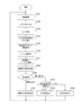
- FIG. 3 is a flowchart illustrating an example of a processing procedure of cell measurement in the first application example of the embodiment of the present technology.
- image data including cells to be measured is acquired (step S811).
- image data including cells to be measured is acquired.
- an image of the cell culture plate is captured by the imaging unit 110 through a microscope.
- the acquired image data constitutes a time-series frame.
- noise other than a certain size is removed (noise reduction) by the filter processing unit 120 (step S812). Then, a contour detection process is performed on the noise-removed frame in the filter processing unit 120 (step S813).
- step S814 a process is selected in accordance with an instruction from the operation input device 310 (step S814).
- the binarization processing unit 130 validates the outline of the frame that has undergone the outline detection process, and binarizes the frame (step S815).
- step S816 When a specific area is set as a measurement target according to an instruction from the operation input device 310 (step S816), a difference between frames adjacent in time series in the specific area is generated by the tracking processing unit 140 (step S817). ). Then, moment calculation is performed by the moment generator 150 for the set specific region (step S818).
- the movement rate of the cell is calculated for each specific region in the totalization processing unit 210 (step S819).
- the calculated cell motility rate is displayed on the display device 320 via the interface 230 (step S821).
- the totalization processing unit 210 obtains the Euler number of the image that has undergone the contour detection processing in the binarization processing unit 130, and thereby includes the objects included in the image. Is calculated (step S822). For example, a desired cell size is preset in nanometer units, and the number of cells having the predetermined size is calculated. The number of contours calculated in this way is displayed on the display device 320 via the interface 230 (step S823).
- the aggregation processing unit 210 calculates the size of the contour included in the image based on the moment generated by the moment generation unit 150 (step S824). Thereby, the size of each of the plurality of cells included in the image is obtained. The aggregation processing unit 210 sorts the obtained cell sizes and obtains the maximum value and the minimum value. The maximum value and the minimum value of the cell size are displayed on the display device 320 via the interface 230 (step S825).
- FIG. 4 is a diagram illustrating an example of cell division measurement in the second application example of the embodiment of the present technology.
- a cell culture plate or the like for culturing cells to be measured is prepared, and a microscope is used as in the above-described example of cell measurement.
- the imaging unit 110 captures an image. Thereby, as shown in the image 621, the movement of the cell can be observed at a high frame rate as a moving image composed of time-series frames.
- noise other than a certain size is removed by the filter processing unit 120 as in the above-described example of cell measurement. Further, in the filter processing unit 120, as shown in an image 612, contour detection processing using a Sobel filter or the like is performed. The image 622 obtained in this way is held as an image 624 showing a state immediately before cell division.
- a specific area is defined as a measurement target by the operation input device 310 as shown in the image 622
- a change in the number of contours is detected in the specific area.
- the number of contours changes as shown in the image 623, it is estimated that cell division has occurred in the specific region.
- a difference between frames is generated at the timing when this cell division occurs, and the target is designated as shown in an image 625 from the result, and tracking starts. Thereby, the operation of the subsequent cells is observed.
- FIG. 5 is a flowchart showing an example of a processing procedure of cell division measurement in the second application example of the embodiment of the present technology.
- image data including cells to be measured is acquired (step S831).
- image data including cells to be measured is acquired (step S831).
- an image of the cell culture plate is captured by the imaging unit 110 through a microscope.
- the acquired image data constitutes a time-series frame.
- noise other than a certain size is removed by the filter processing unit 120 (step S832). Then, the filter processing unit 120 performs contour detection processing on the noise-removed frame (step S833).
- processing is selected in accordance with an instruction from the operation input device 310 (step S834).
- the binarization processing unit 130 validates the inside of the outline of the frame for which the outline detection process has been performed, and the frame is binarized (Ste S835). Thereafter, the process waits until a change in the number of contours is detected (step S836).
- the totalization processing unit 210 calculates the Euler number of the image subjected to the contour detection processing in the binarization processing unit 130.
- the number of contours is calculated (step S844).
- the calculated number of contours is displayed on the display device 320 via the interface 230 (step S845).
- the control unit 220 notifies the tracking processing unit 140 accordingly (step S846).
- step S836 When notification of change in the number of contours is notified (step S836), the tracking processing unit 140 generates a difference between frames adjacent in time series (step S837). From this result, a target to be tracked is set (step S838), and target tracking by the tracking processing unit 140 is started (step S839). Then, the moment calculation is performed by the moment generator 150 for the set target (step S841).
- the individual movement amount for each frame is calculated by the centroid position generation unit 160 (step S842). Further, the individual movement amount for each frame is totalized in the totalization processing unit 210, and the total movement amount such as average speed and speed variation is obtained as the total result of the plurality of frames. Then, the individual movement amount and the total movement amount obtained in this way are displayed on the display device 320 via the interface 230 (step S843).
- FIG. 6 is a diagram illustrating an example of cell motion measurement in the third application example of the embodiment of the present technology.
- a cell culture plate or the like for culturing cells to be measured is prepared, and a microscope is used as in the above-described example of cell measurement.
- the imaging unit 110 captures an image.
- an image 631 the movement of cells can be observed at a high frame rate as a moving image composed of time-series frames.
- the binarization processing unit 130 performs binarization processing.
- the start of data analysis can be defined by detecting the movement of a specific target and using it as a trigger. Thereby, unnecessary image analysis load can be reduced.
- the moving speed of the cells can be calculated by performing target tracking in the tracking processing unit 140. Thereby, for example, malignancy of cancer cells and the like can be determined.
- the rate of about 150 fps like sperm, and the rate of moving steadily within a specific area even for irregularly moving objects can be measured.
- FIG. 7 is a flowchart illustrating an example of a processing procedure of cell motion measurement in the third application example of the embodiment of the present technology.
- image data including cells to be measured is acquired (step S851).
- image data including cells to be measured is acquired (step S851).
- an image of the cell culture plate is captured by the imaging unit 110 through a microscope.
- the acquired image data constitutes a time-series frame.
- step S852 In the acquired frames, noise other than a certain size is removed by the filter processing unit 120 (step S852). Then, with respect to the frame from which noise has been removed, the filter processing unit 120 removes an object having a size equal to or smaller than the specified size (step S853).
- processing is selected in accordance with an instruction from the operation input device 310 (step S854).
- the binarization processing unit 130 performs frame binarization processing (step S855).
- the tracking processing unit 140 When a single individual is set as a measurement target in accordance with an instruction from the operation input device 310 (step S856), the tracking processing unit 140 generates a difference between frames adjacent in time series for the single individual (step S857). ). Then, moment calculation is performed by the moment generator 150 for the single individual (step S858). Further, the individual movement amount (movement speed) is calculated by the gravity center position generation unit 160 for the single individual (step S859). The individual movement amount obtained in this way is displayed on the display device 320 via the interface 230 (step S861).
- the tracking processing unit 140 When a plurality of individuals are set as measurement targets according to an instruction from the operation input device 310 (step S856), the tracking processing unit 140 generates a difference between adjacent frames in time series for each of the plurality of individuals (step S856). Step S862). Then, moment calculation is performed by the moment generator 150 for the plurality of individuals (step S863). Thereafter, the individual movement amount is calculated by the barycentric position generation unit 160 for a plurality of individuals (step S864). The aggregation processing unit 210 sorts the obtained individual movement amounts and obtains the maximum value and the minimum value. The maximum value and the minimum value of these individual movement amounts are displayed on the display device 320 via the interface 230 (step S865).
- the totalization processing unit 210 calculates the number of objects included in the image by obtaining the Euler number of the image (step S866). For example, a desired cell size is preset in nanometer units, and the number of cells having the predetermined size is calculated. The number thus calculated is displayed on the display device 320 via the interface 230 (step S867).
- the aggregation processing unit 210 calculates the size of the object included in the image based on the moment generated by the moment generation unit 150 (step S868). Thereby, each size of the some target object contained in an image is obtained.
- the aggregation processing unit 210 sorts the obtained object sizes and obtains the maximum value and the minimum value. The maximum value and the minimum value of the size of these objects are displayed on the display device 320 via the interface 230 (step S869).
- FIG. 8 is a diagram illustrating an example of blink detection and line-of-sight detection in the fourth application example of the embodiment of the present technology.
- a speed of 60 to 125 fps is required to capture the human blinking operation, but the human eye is imaged as an object using the image processing system in the present embodiment, and the pupil area and duration are generated. By doing so, it can be determined whether or not blinking is performed. Further, the line-of-sight direction can be determined by generating the center of gravity of the pupils of both eyes.
- FIG. 9 is a flowchart illustrating an example of a processing procedure of blink detection and line-of-sight detection in the fourth application example of the embodiment of the present technology.
- image data including a human eye to be measured is acquired (step S871). Therefore, for example, a wearable device or an eyewear device can be used as the imaging unit 110.
- step S873 binarization processing is performed in the binarization processing unit 130, and a pupil region is detected (step S872). Further, the tracking processing unit 140 tracks the movement of the pupil (step S873).
- the center of gravity of the pupil is calculated by the gravity center position generation unit 160 (step S874), the moment calculation is performed by the moment generation unit 150, and the area of the pupil is calculated (step S875). . Thereby, blinking is detected. Further, based on the center of gravity of the pupil generated by the center-of-gravity position generation unit 160, the line-of-sight direction is determined in the totalization processing unit 210 (step S876). For example, when the user views an image floating in a space 30 cm ahead as the image, it is assumed that the tabulation processing unit 210 corrects the coordinate information of the pupil generated by the gravity center position generation unit 160.
- step S881 determines that blinking of the left eye has been detected.
- step S883 determines that blinking of the right eye has been detected.
- step S884 determines with blinking of both eyes having been detected.
- step S873 If any of these blinks is detected, control for re-detection is performed when the pupil is completely hidden by blinking (step S878). Then, screen drawing is performed on the display device 320 (step S879). Thereafter, the processing after step S873 is repeated.
- the pupil is detected and its area is calculated, but the iris may be detected and the area calculated.
- FIG. 10 is a diagram illustrating an example of blood flow velocity measurement in the fifth application example of the embodiment of the present technology.
- Zebrafish are small carp of the cyprinid family and are the most developed model vertebrates in the last decade. This zebrafish is known to be suitable for studying the formation of the brain and internal organs because it shows through the body. On the other hand, a speed of 600 fps is required to capture the blood flow of the zebrafish. In the image processing system according to the present embodiment, the zebrafish blood flow is imaged at a high frame rate to enable observation thereof.
- a harmless color ball is swallowed into the zebrafish as an object to be imaged. Then, as shown in the image 651, at the moment when the color ball 655 appears in the frame, the recording is started together with the frame display 656 shown in the image 652. Then, as shown in an image 653, recording can be stopped when the color ball 655 has completely flowed, and the speed can be obtained from the number of frames.
- FIG. 11 is a flowchart illustrating an example of a processing procedure of blood flow velocity measurement in the fifth application example of the embodiment of the present technology.
- image data to be measured is acquired (step S711). Therefore, for example, an image of a blood flow portion of zebrafish can be captured by the imaging unit 110 via a microscope.
- step S712 In the acquired frames, noise other than a certain size is removed by the filter processing unit 120 (step S712). Further, binarization processing is performed in the binarization processing unit 130 in accordance with the color component of the image data (step S713).
- step S714 a difference between frames adjacent in time series is generated by the tracking processing unit 140, and a moving object in the region designated by the operation input device 310 is searched.
- the process waits until a moving object is detected (step S715).
- step S716 When a single unit is designated as a tracking target by the operation input device 310 (step S716), the tracking processing unit 140 performs target tracking for the single unit (step S717). Then, the moment calculation unit 150 performs moment calculation for the single unit (step S718). Further, the individual movement amount of the single unit is calculated by the gravity center position generation unit 160 (step S719). The individual movement amount obtained in this way is displayed on the display device 320 via the interface 230 (step S721).
- step S716 target tracking is performed on the plurality of individuals in the tracking processing unit 140 (step S722). Then, moment calculation is performed by the moment generator 150 for the plurality of individuals (step S723). Further, for each of the plurality of individuals, the individual movement amount is calculated by the centroid position generation unit 160 (step S724). The aggregation processing unit 210 sorts the obtained individual movement amounts and obtains the maximum value and the minimum value. The maximum value and the minimum value of these individual movement amounts are displayed on the display device 320 via the interface 230 (step S725).
- the example of blood flow velocity measurement and statistical value calculation is shown.
- the expected value stored in the database the expected value range is not satisfied. An abnormality may be detected.
- FIG. 12 is a diagram illustrating an example of malfunction detection by vibration amount measurement in the sixth application example of the embodiment of the present technology.
- the vibration sensor normally used to measure the vibration amount of the device needs to be directly connected to the device, and not only is it necessary to fix it to the device, but also safety must be taken into consideration.
- the frequency of the primary vibration of the engine whose rotation speed is 1200 rpm (rotation per minute) during idling is about 20 Hz, but is about 200 Hz during operation.
- the appearance of the device is imaged at a high frame rate to enable observation.
- the position and width to be observed are designated by the operation input device 310 as a frame 662 or 663 on the image.
- the malfunction of the device 661 can be detected by observing the operation in the frames arranged in time series and comparing with the expected value for each region.
- FIG. 13 is a flowchart illustrating a processing procedure example of malfunction detection by vibration amount measurement in the sixth application example of the embodiment of the present technology.
- image data to be measured is acquired (step S731).
- an image of the measurement target device is captured by the imaging unit 110.
- the noise is removed from each acquired frame by the filter processing unit 120 (step S732). Further, edge detection is performed by the filter processing unit 120 (step S733). Then, binarization processing for validating the detected edge portion is performed by the binarization processing unit 130 (step S734).
- the region to be observed is set by the operation input device 310 in the frame of the image data to be measured (step S735).
- the set area is supplied from the control unit 220 to the tracking processing unit 140.
- the tracking processing unit 140 generates a difference between adjacent frames in time series (step S736). Then, moment calculation is performed by the moment generator 150 for each set region (step S737). Based on the moment generated for each region, the vibration factor for each region is calculated in the totalization processing unit 210 (step S738).
- step S739 a process is selected according to an instruction from the operation input device 310 (step S739).
- the vibration factor for each region calculated in the totalization processing unit 210 is displayed on the display device 320 via the interface 230 (step S741).
- step S739 When the determination of the expected value of the vibration amount is instructed (step S739), the expected value held in the database or the like is compared with the vibration rate for each area calculated in the totalization processing unit 210. If the vibration rate is within the range of the expected value (step S742: Yes), the determination result that it is normal is displayed on the display device 320 via the interface 230 (step S743). On the other hand, if the vibration rate is significantly different from the expected value (step S742: No), a determination result indicating that an abnormality has occurred is displayed on the display device 320 via the interface 230 (step S744).
- FIG. 14 is a diagram illustrating an example of malfunction detection by rotation amount measurement in the seventh application example of the embodiment of the present technology.
- a propeller is provided in the main part of a device such as a drone or a ventilation fan, it is possible to detect a malfunction by observing the amount of rotation of the propeller that is the object. For example, it is about 1500 to 1600 rpm for a household fan and about 2500 rpm for a kitchen ventilation fan. Further, the screw of the boat is about 5000 to 6000 rpm at full throttle, the propeller of the propeller machine is about 2300 to 2400 rpm, and the radio control or drone is about 1300 to 2500 rpm.
- Boat screws and propeller propellers can be measured with the built-in tachometer, but it is also possible to detect malfunctions by objective observation from the outside because tachometer failures may occur.
- the appearance of the device is imaged at a high frame rate to enable observation.
- the propeller portion of the drone 671 is taken as an object by the camera of the portable terminal 672.
- the amount of movement can be measured by attaching a sticker as a marker to a specific one of the plurality of propellers and performing target tracking. It is also possible to track the shape obtained by performing edge detection.
- the rotation rate of the imaged propeller portion can be displayed on the display unit of the mobile terminal 672 in real time.
- FIG. 15 is a flowchart illustrating a processing procedure example of malfunction detection by rotation amount measurement in the seventh application example of the embodiment of the present technology.
- image data to be measured is acquired (step S751).
- the imaging unit 110 captures an image of the propeller portion of the measurement target device.
- the noise is removed from the acquired frames by the filter processing unit 120 (step S752). Then, binarization processing by color and luminance is performed by the binarization processing unit 130, and the marker of the sticker attached to the propeller portion is detected (step S753).
- a region on the image is set for the detected marker (step S754), and the target tracking is performed by the tracking processing unit 140 (step S755). Further, the moment calculation is performed by the moment generator 150 for the set region (step S756). Then, based on the generated moment, the rotation rate is calculated in the totalization processing unit 210 (step S757).
- step S758 processing is selected in accordance with an instruction from the operation input device 310 (step S758).
- the rotation rate calculated in the totalization processing unit 210 is displayed on the display device 320 via the interface 230 (step S759).
- step S758 When an instruction for determining the expected value of the rotation rate is instructed (step S758), the expected value held in the database or the like is compared with the rotation rate calculated by the totalization processing unit 210. If the rotation rate is within the range of the expected value (step S761: Yes), the determination result that it is normal is displayed on the display device 320 via the interface 230 (step S762). On the other hand, if the rotation rate is significantly different from the expected value (step S761: No), a determination result indicating that an abnormality has occurred is displayed on the display device 320 via the interface 230 (step S763).
- a measurement result can be quantified without outputting image data by imaging an object (object or device) at a high frame rate and performing image processing in the image sensor.
- the time required for image analysis can be shortened and the amount of data storage to be held can be reduced.
- the calculation result can be generated at the sensor level, it can be realized even in a small system including a portable device.
- the processing procedure described in the above embodiment may be regarded as a method having a series of these procedures, and a program for causing a computer to execute these series of procedures or a recording medium storing the program. You may catch it.
- a recording medium for example, a CD (Compact Disc), an MD (MiniDisc), a DVD (Digital Versatile Disc), a memory card, a Blu-ray disc (Blu-ray (registered trademark) Disc), or the like can be used.
- this technique can also take the following structures.
- an image sensor that images a target and generates frames of image data arranged in time series;
- a binarization processing unit that performs binarization processing on each of the frames to generate a binarized frame;
- An image sensor comprising: a tracking processing unit that generates a difference between the binarized frames adjacent to each other in time series and tracks a change in the position of the object included in the binarized frame.
- the method further includes a moment generation unit that calculates a moment of the binarized frame based on a result of the tracking processing unit and generates a change amount of the area of the object included in the binarized frame.
- the image sensor according to (3) further including a centroid position generation unit that generates a centroid position of the object included in the binarized frame based on the moment generated by the moment generation unit. .
- the image sensor according to (4) further including an aggregation processing unit that performs aggregation processing on the object based on the gravity center position of the object generated by the gravity center position generation unit.
- the image sensor according to (5) further including a display control unit for displaying a result of the aggregation processing by the aggregation processing unit.
- the counting processing unit counts at least one of the number, size, and motion rate of the object.
- the aggregation processing unit detects a shape change of the object, The image sensor according to (5), wherein the tracking processing unit starts the tracking when a change in shape of the object is detected.
- the image sensor according to (5), wherein the aggregation processing unit measures the speed of the target object and calculates a statistical value of the speed of the target object when there are a plurality of the target objects.
- the imaging element images a living eye as the object
- the binarization processing unit detects a pupil in the imaged biological eye
- the tracking processing unit tracks a line of sight in the captured biological eye
- the moment generation unit calculates the area of the pupil in the captured biological eye
- the image sensor according to (5) wherein the aggregation processing unit detects blinking from the area of the pupil and the time during which the pupil is continuously recognized.
- the image sensor according to (10) further including an interface that accepts an operation input according to an embodiment of the blinking.
- the barycentric position generation unit generates a barycentric position of a pupil in the captured biological eye
- the image sensor according to (10) wherein the aggregation processing unit determines a line-of-sight direction from a center of gravity position of the pupil.
- the totalization processing unit controls the binarization processing unit so as to perform detection of the pupil again when the blinking is detected.
- the aggregation processing unit measures the speed of the object and detects an abnormality when the speed of the object does not satisfy a predetermined condition.
- the aggregation processing unit measures a rotation amount of the object and detects an abnormality when the rotation amount of the object does not satisfy a predetermined condition.
Landscapes
- Engineering & Computer Science (AREA)
- Physics & Mathematics (AREA)
- Theoretical Computer Science (AREA)
- General Physics & Mathematics (AREA)
- Multimedia (AREA)
- Health & Medical Sciences (AREA)
- Life Sciences & Earth Sciences (AREA)
- Human Computer Interaction (AREA)
- Computer Vision & Pattern Recognition (AREA)
- General Health & Medical Sciences (AREA)
- Ophthalmology & Optometry (AREA)
- Signal Processing (AREA)
- General Engineering & Computer Science (AREA)
- Molecular Biology (AREA)
- Biomedical Technology (AREA)
- Public Health (AREA)
- Veterinary Medicine (AREA)
- Heart & Thoracic Surgery (AREA)
- Surgery (AREA)
- Animal Behavior & Ethology (AREA)
- Biophysics (AREA)
- Geometry (AREA)
- Medical Informatics (AREA)
- Remote Sensing (AREA)
- Radar, Positioning & Navigation (AREA)
- Electromagnetism (AREA)
- Computing Systems (AREA)
- Optics & Photonics (AREA)
- Image Analysis (AREA)
- Eye Examination Apparatus (AREA)
- Transforming Light Signals Into Electric Signals (AREA)
Abstract
画像センサにおいて、表示のための低速画像データとは異なる高速画像データを用いて、高速な認識処理を行う。 画像センサにおいて、撮像素子は、対象物を撮像して時系列に並ぶ画像データのフレームを生成する。二値化処理部は、フレームの各々に対して二値化処理を行って二値化フレームを生成する。トラッキング処理部は、時系列に隣接する二値化フレームの間の差分を生成して二値化フレームに含まれる対象物の位置の変化を追跡する。
Description
本技術は、画像センサに関する。詳しくは、撮像された画像データを利用して認識処理を行うための画像センサに関する。
従来、撮像された画像データを利用して様々な認識処理が行われている。そのような認識処理の一例として、撮像された画像データから人の身振りや手振りなどのジェスチャを操作情報として認識するマンマシンインターフェースが組み込まれた端末装置が提案されている(例えば、特許文献1参照。)。
上述の従来技術では、画像データを表示画像として出力するデータフローと、画像データから必要な情報を抽出して認識処理を行うデータフローとに大別される。画像を表示するためには、一般に30乃至120fps(フレーム/秒)程度の処理速度で足りるが、高度な認識処理を行うためにはそれでは不十分である。すなわち、通常のカメラで捉えた低フレームレート画像では、フレーム画像間隔が広いため、画像処理を用いた物体の移動量や、移動速度、回転速度などといった動作に基づく測定においてはリアルタイム性が低くなり、動作物体の計測に不向きである。また、高速に動作する物体検出に対応するためには、フレーム補間などの処理が必要になるが、そのような画像を解析するためには、画像を保持するための大容量のデータベースと多大な処理時間とが必要となってしまう。
本技術はこのような状況に鑑みて生み出されたものであり、認識処理に必要な処理部を画像センサに設けて、表示のための低速画像データとは異なる高速画像データを用いて高速な認識処理を行うことを目的とする。
本技術は、上述の問題点を解消するためになされたものであり、その第1の側面は、対象物を撮像して時系列に並ぶ画像データのフレームを生成する撮像素子と、上記フレームの各々に対して二値化処理を行って二値化フレームを生成する二値化処理部と、時系列に隣接する上記二値化フレームの間の差分を生成して上記二値化フレームに含まれる上記対象物の位置の変化を追跡するトラッキング処理部とを具備する画像センサである。これにより、撮像されたフレームを画像センサ内において二値化して対象物の追跡を行うという作用をもたらす。
また、この第1の側面において、上記フレームの各々に対してフィルタ処理を施すフィルタ処理部をさらに具備し、上記二値化処理部は、上記フィルタ処理の施されたフレームの各々に対して上記二値化処理を行うようにしてもよい。これにより、フレームの各々に対してフィルタ処理を施すという作用をもたらす。
また、この第1の側面において、上記トラッキング処理部による結果に基づいて上記二値化フレームに含まれる前記対象物のモーメントを算出するモーメント生成部をさらに具備してもよい。これにより、二値化フレームに含まれる対象物の面積の変化量を生成するという作用をもたらす。
また、この第1の側面において、上記モーメント生成部によって生成された上記モーメントに基づいて上記二値化フレームに含まれる上記対象物の重心位置を生成する重心位置生成部をさらに具備してもよい。これにより、二値化フレームに含まれる対象物の重心位置を生成するという作用をもたらす。
また、この第1の側面において、上記重心位置生成部によって生成された上記対象物の重心位置に基づいて上記対象物に関する集計処理を行う集計処理部をさらに具備してもよい。これにより、対象物に関する集計処理を行うという作用をもたらす。
また、この第1の側面において、上記集計処理部による上記集計処理の結果を表示させるための表示制御部をさらに具備してもよい。これにより、集計処理の結果を表示させるという作用をもたらす。
また、この第1の側面において、上記集計処理部は、上記対象物の個数、サイズ、および、運動率の少なくとも何れか一つを集計するようにしてもよい。これにより、対象物の個数、サイズ、および、運動率を集計するという作用をもたらす。
また、この第1の側面において、上記集計処理部は、上記対象物の形状変化を検出し、上記トラッキング処理部は、上記対象物の形状変化が検出されると上記追跡を開始してもよい。これにより、対象物の形状変化をトリガとして対象物を追跡させるという作用をもたらす。
また、この第1の側面において、上記集計処理部は、上記対象物の速度を計測し、上記対象物が複数ある場合にそれら対象物の速度の統計値を算出するようにしてもよい。これにより、複数の対象物の速度の統計値を算出するという作用をもたらす。
また、この第1の側面において、上記撮像素子は、上記対象物として生体の眼を撮像し、上記二値化処理部は、上記撮像された生体の眼において瞳孔を検出し、上記トラッキング処理部は、上記撮像された生体の眼における視線を追跡し、上記モーメント生成部は、上記撮像された生体の眼における瞳孔の面積を算出し、上記集計処理部は、上記瞳孔の面積と上記瞳孔が継続して認識されている時間とからまばたきの実施を検出するようにしてもよい。これにより、撮像された眼からまばたきの実施を検出するという作用をもたらす。また、この場合において、上記まばたきの実施の態様に応じて操作入力を受け付けるインターフェースをさらに具備してもよい。これにより、まばたきの実施の態様に応じた操作入力を行うという作用をもたらす。
また、この第1の側面において、上記重心位置生成部は、上記撮像された生体の眼における瞳孔の重心位置を生成し、上記集計処理部は、上記瞳孔の重心位置から視線方向を判定するようにしてもよい。これにより、撮像された眼から視線方向を判定するという作用をもたらす。また、この場合において、上記まばたきの実施の態様および上記視線方向に応じて操作入力を受け付けるインターフェースをさらに具備してもよい。これにより、まばたきの実施の態様および視線方向に応じた操作入力を行うという作用をもたらす。
また、この第1の側面において、上記集計処理部は、上記まばたきの実施が検出されると上記瞳孔の検出を再度行うよう上記二値化処理部を制御するようにしてもよい。これにより、まばたきの実施をトリガとして、瞳孔の検出を再開するという作用をもたらす。
また、この第1の側面において、上記集計処理部は、上記対象物の速度を計測し、上記対象物の速度が所定の条件を満たさない場合には異常を検知するようにしてもよい。これにより、撮像された対象物の速度により異常を検知するという作用をもたらす。
また、この第1の側面において、上記集計処理部は、上記対象物の振動量を計測し、上記対象物の振動量が所定の条件を満たさない場合には異常を検知するようにしてもよい。これにより、撮像された対象物の振動量により異常を検知するという作用をもたらす。
また、この第1の側面において、上記集計処理部は、上記対象物の回転量を計測し、上記対象物の回転量が所定の条件を満たさない場合には異常を検知するようにしてもよい。これにより、撮像された対象物の回転量により異常を検知するという作用をもたらす。
本技術によれば、画像センサにおいて高速な認識処理を行うことができるという優れた効果を奏し得る。なお、ここに記載された効果は必ずしも限定されるものではなく、本開示中に記載されたいずれかの効果であってもよい。
以下、本技術を実施するための形態(以下、実施の形態と称する)について説明する。説明は以下の順序により行う。
1.実施の形態(画像処理システムの構成例)
2.第1の適用例(細胞計測の例)
3.第2の適用例(細胞分裂計測の例)
4.第3の適用例(細胞動作計測の例)
5.第4の適用例(まばたき検出および視線検出の例)
6.第5の適用例(血流速度計測の例)
7.第6の適用例(振動量計測による不調検出の例)
8.第7の適用例(回転量計測による不調検出の例)
1.実施の形態(画像処理システムの構成例)
2.第1の適用例(細胞計測の例)
3.第2の適用例(細胞分裂計測の例)
4.第3の適用例(細胞動作計測の例)
5.第4の適用例(まばたき検出および視線検出の例)
6.第5の適用例(血流速度計測の例)
7.第6の適用例(振動量計測による不調検出の例)
8.第7の適用例(回転量計測による不調検出の例)
<1.実施の形態>
図1は、本技術の実施の形態における画像処理システムの一構成例を示す図である。この実施の形態における画像処理システムは、画像センサ100と、集計部200と、操作入力装置310と、表示装置320とを備える。
図1は、本技術の実施の形態における画像処理システムの一構成例を示す図である。この実施の形態における画像処理システムは、画像センサ100と、集計部200と、操作入力装置310と、表示装置320とを備える。
画像センサ100は、対象物を含む被写体を撮像して、対象物の認識処理を行うものである。集計部200は、画像センサ100によって得られた各種データに基づいて集計を行うものである。操作入力装置310は、外部からの操作入力を受け付けるものである。表示装置320は、集計部200によって得られた集計結果を表示するものである。
なお、ここでは一例として、集計部200の各機能が画像センサ100から独立した態様について説明するが、集計部200の一部または全部の機能を画像センサ100に組み込むような態様であってもよい。
画像センサ100は、撮像部110と、フィルタ処理部120と、二値化処理部130と、トラッキング処理部140と、モーメント生成部150と、重心位置生成部160とを備える。
撮像部110は、対象物を含む被写体を撮像する撮像素子である。この撮像部110は、所定のフレームレートにより、時系列に並ぶ画像データのフレームを生成する。ここで、フレームレートとしては、1秒当たり1000フレーム(1000fps)以上の高フレームレートを想定する。この撮像部110によって撮像された画像データのフレームは、その全てが画像センサ100の外部に供給される必要はない。高フレームレートの画像データは以下に説明する認識処理を目的としたものであり、表示のためにはこれよりも低いフレームレートで十分である。すなわち、高フレームレートの画像データを画像センサ100内の参照に留めることにより、画像センサ100のバンド幅を有効に活用することが可能となる。なお、撮像部110は、特許請求の範囲に記載の撮像素子の一例である。また、対象物は、人物や動物などの生物のみならず、非生物を広く含むオブジェクトである。
フィルタ処理部120は、撮像部110によって撮像された画像データのフレームの各々に対してフィルタ処理を施すものである。このフィルタ処理部120におけるフィルタ処理としては、例えば、移動平均フィルタやメディアンフィルタなどによるノイズ除去処理、Sobelフィルタなどによる輪郭検出処理、ラプラシアンフィルタなどによるエッジ検出などが想定される。また、このフィルタ処理部120によって画像のオイラー数を求めることにより、画像に含まれる対象物の個数を算出することも可能である。オイラー数とは、成分数から孔の数を引いた数である。
二値化処理部130は、フィルタ処理部120によってフィルタ処理の施されたフレームの各々に対して二値化処理を行うものである。この二値化処理部130は、各フレームの画像データに含まれる輝度や色のヒストグラム情報に基づいてその画像データを二値化して、二値化データからなる二値化フレームを生成する。
トラッキング処理部140は、二値化処理部130によって生成された二値化フレームについて、時系列に隣接するフレーム間の差分を生成することにより、二値化フレームに含まれる対象物を検出して、その対象物の位置の変化を追跡するものである。対象物の検出の際には、画像における特定の領域を測定対象として指定することが可能である。
モーメント生成部150は、トラッキング処理部140による結果に基づいて、二値化フレームにおける2変数関数のモーメントを算出するものである。0次モーメントは、その二値化フレームに含まれる対象物の面積の変化量を表し、画像の回転や拡大縮小に対して不変な値である。
重心位置生成部160は、モーメント生成部150によって生成されたモーメントに基づいて、二値化フレームに含まれる対象物の重心位置を生成するものである。水平方向および垂直方向の各1次モーメントをそれぞれ0次モーメントで除算した値が、重心位置を表す。
集計部200は、集計処理部210と、制御部220と、インターフェース230とを備える。集計処理部210は、画像センサ100によって得られた各種データに基づいて集計処理を行うものである。この集計処理部210は、以下の適用例に示すように、動作するアプリケーションに応じて必要な処理を行う。制御部220は、集計部200および画像センサ100の各部に対する動作制御を行うものである。インターフェース230は、外部とのインターフェースを司るものである。この例では、インターフェース230は表示装置320と接続して、集計部200によって得られた集計結果を表示装置320に表示させるための入出力制御を行う。なお、インターフェース230は、特許請求の範囲に記載のインターフェースおよび表示制御部の一例である。
なお、この図においては、重心位置生成部160からの出力が集計処理部210および制御部220に供給される経路を明示しているが、画像センサ100の各部から集計部200に対して各種データを供給する経路が必要に応じて設けられてもよい。
このように構成することにより、認識処理に合わせてフレーム単位の処理の中にプログラム演算を埋め込むことができ、対象物の移動量およびサイズ、移動方向、ヒストグラム情報といったフレーム毎の演算結果をセンシング情報として高速に出力することができる。また、後段において画像を処理する必要がなく、演算結果のみを利用して解析を行うことができる。
<2.第1の適用例>
図2は、本技術の実施の形態の第1の適用例における細胞計測の例を示す図である。本実施の形態における画像処理システムを用いて細胞計測を行うためには、測定の対象物となる細胞を培養する細胞培養プレート等を用意し、顕微鏡を介して撮像部110によって撮像する。これにより、画像611に示すように時系列のフレームからなる動画像として細胞の動きを、高フレームレートにより観測することができる。
図2は、本技術の実施の形態の第1の適用例における細胞計測の例を示す図である。本実施の形態における画像処理システムを用いて細胞計測を行うためには、測定の対象物となる細胞を培養する細胞培養プレート等を用意し、顕微鏡を介して撮像部110によって撮像する。これにより、画像611に示すように時系列のフレームからなる動画像として細胞の動きを、高フレームレートにより観測することができる。
撮像された各フレームは、フィルタ処理部120によって、一定サイズ以外のノイズが除去される。また、フィルタ処理部120において、画像612に示すように、Sobelフィルタなどによる輪郭検出処理が行われる。
フィルタ処理部120において輪郭検出処理が行われた後、二値化処理部130において輪郭内の有効化が行われて、画像613に示すように二値化される。白い部分が個々の細胞を示す。
二値化された画像613に基づいて、トラッキング処理部140においてフレーム間の差分が生成され、各細胞の動きが追跡される。また、モーメント生成部150においてモーメントが計算される。
画像614に示すように操作入力装置310によって特定の領域が測定対象として定義されると、この特定の領域においてフレーム間差分およびモーメント演算が行われ、その特定の領域における細胞の運動率が算出される。また、画像615に示すように操作入力装置310によって複数の領域が測定対象として定義されると、その複数の領域毎に細胞の運動率が算出される。
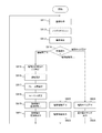
図3は、本技術の実施の形態の第1の適用例における細胞計測の処理手順例を示す流れ図である。
まず、測定対象となる細胞を含む画像データが取得される(ステップS811)。そのために、例えば顕微鏡を介して細胞培養プレートの画像が撮像部110によって撮像される。取得された画像データは、時系列のフレームを構成する。
取得された各フレームは、フィルタ処理部120によって、一定サイズ以外のノイズが除去(ノイズリダクション)される(ステップS812)。そして、そのノイズ除去されたフレームについて、フィルタ処理部120において、輪郭検出処理が行われる(ステップS813)。
その後、操作入力装置310からの指示に従って処理が選択される(ステップS814)。細胞の運動率の算出が選択されると、二値化処理部130において輪郭検出処理が行われたフレームの輪郭内の有効化が行われて、フレームは二値化される(ステップS815)。
操作入力装置310からの指示により特定の領域が測定対象として設定されると(ステップS816)、この特定の領域において時系列に隣接するフレーム間の差分がトラッキング処理部140によって生成される(ステップS817)。そして、設定された特定の領域について、モーメント生成部150によってモーメント演算が行われる(ステップS818)。
演算されたモーメントに基づいて、集計処理部210において特定の領域毎に細胞の運動率が算出される(ステップS819)。算出された細胞の運動率は、インターフェース230を介して表示装置320に表示される(ステップS821)。
輪郭個数の算出が選択されると(ステップS814)、集計処理部210は、二値化処理部130において輪郭検出処理が行われた画像のオイラー数を求めることにより、その画像に含まれる対象物の個数を算出する(ステップS822)。例えば、所望の細胞のサイズをナノメートル単位で予め設定しておいて、その所定サイズの細胞がいくつあるかを計算する。このようにして算出された輪郭個数は、インターフェース230を介して表示装置320に表示される(ステップS823)。
輪郭サイズの算出が選択されると(ステップS814)、集計処理部210は、モーメント生成部150によって生成されたモーメントに基づいて画像に含まれる輪郭のサイズを算出する(ステップS824)。これにより、画像に含まれる複数の細胞のそれぞれのサイズが得られる。集計処理部210は、得られた細胞のサイズをソートして、その最大値および最小値を求める。これら細胞のサイズの最大値および最小値は、インターフェース230を介して表示装置320に表示される(ステップS825)。
これらの処理は、時系列に並ぶ画像データのフレームのそれぞれについて繰り返し行われる。
なお、この例においては、集計処理部210が独立して動作することを想定しているため、ステップS815乃至S818の処理とステップS822乃至S825の処理とは、互いに並列に実行することができる。
<3.第2の適用例>
図4は、本技術の実施の形態の第2の適用例における細胞分裂計測の例を示す図である。本実施の形態における画像処理システムを用いて細胞分裂計測を行うためには、上述の細胞計測の例と同様に、測定の対象物となる細胞を培養する細胞培養プレート等を用意し、顕微鏡を介して撮像部110によって撮像する。これにより、画像621に示すように時系列のフレームからなる動画像として細胞の動きを、高フレームレートにより観測することができる。
図4は、本技術の実施の形態の第2の適用例における細胞分裂計測の例を示す図である。本実施の形態における画像処理システムを用いて細胞分裂計測を行うためには、上述の細胞計測の例と同様に、測定の対象物となる細胞を培養する細胞培養プレート等を用意し、顕微鏡を介して撮像部110によって撮像する。これにより、画像621に示すように時系列のフレームからなる動画像として細胞の動きを、高フレームレートにより観測することができる。
撮像された各フレームは、上述の細胞計測の例と同様に、フィルタ処理部120によって、一定サイズ以外のノイズが除去される。また、フィルタ処理部120において、画像612に示すように、Sobelフィルタなどによる輪郭検出処理が行われる。このようにして得られた画像622は、細胞分裂の直前の状態を示す画像624として保持される。
画像622に示すように操作入力装置310によって特定の領域が測定対象として定義されると、この特定の領域において輪郭個数の変化が検知される。画像623に示すように輪郭の個数が変化した場合、その特定の領域において細胞の分裂が発生したと推定される。この細胞分裂が発生したタイミングでフレーム間の差分が生成され、その結果からターゲットが画像625に示すように指定されてトラッキングが開始する。これにより、その後の細胞の動作が観測される。
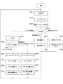
図5は、本技術の実施の形態の第2の適用例における細胞分裂計測の処理手順例を示す流れ図である。
まず、測定対象となる細胞を含む画像データが取得される(ステップS831)。そのために、例えば顕微鏡を介して細胞培養プレートの画像が撮像部110によって撮像される。取得された画像データは、時系列のフレームを構成する。
取得された各フレームは、フィルタ処理部120によって、一定サイズ以外のノイズが除去される(ステップS832)。そして、そのノイズ除去されたフレームについて、フィルタ処理部120において、輪郭検出処理が行われる(ステップS833)。
その後、操作入力装置310からの指示に従って処理が選択される(ステップS834)。画像センサ100内のハードウェアによる連動処理が選択されると、二値化処理部130において輪郭検出処理が行われたフレームの輪郭内の有効化が行われて、フレームは二値化される(ステップS835)。その後、輪郭個数の変化が検知されるまで待機される(ステップS836)。
一方、集計部200における輪郭個数の変化検知が選択されると(ステップS834)、集計処理部210は、二値化処理部130において輪郭検出処理が行われた画像のオイラー数を求めることにより、輪郭の個数を算出する(ステップS844)。算出された輪郭個数は、インターフェース230を介して表示装置320に表示される(ステップS845)。そして、輪郭個数の変化が検知されると、制御部220はトラッキング処理部140にその旨を通知する(ステップS846)。
輪郭個数の変化検知が通知されると(ステップS836)、トラッキング処理部140は、時系列に隣接するフレーム間の差分を生成される(ステップS837)。この結果から追跡すべきターゲットが設定され(ステップS838)、トラッキング処理部140によるターゲットトラッキングが開始する(ステップS839)。そして、設定されたターゲットについて、モーメント生成部150によってモーメント演算が行われる(ステップS841)。
そして、フレーム毎の個別移動量が重心位置生成部160によって算出される(ステップS842)。また、フレーム毎の個別移動量が集計処理部210において集計され、複数のフレームの集計結果として、平均速度や速度のばらつき等の集計移動量が得られる。そして、このようにして得られた個別移動量や集計移動量は、インターフェース230を介して表示装置320に表示される(ステップS843)。
これらの処理は、時系列に並ぶ画像データのフレームのそれぞれについて繰り返し行われる。
なお、この例においては、集計処理部210が独立して動作することを想定しているため、ステップS835乃至S841の処理とステップS844乃至S846の処理とは、互いに並列に実行することができる。
<4.第3の適用例>
図6は、本技術の実施の形態の第3の適用例における細胞動作計測の例を示す図である。本実施の形態における画像処理システムを用いて細胞動作計測を行うためには、上述の細胞計測の例と同様に、測定の対象物となる細胞を培養する細胞培養プレート等を用意し、顕微鏡を介して撮像部110によって撮像する。これにより、画像631に示すように時系列のフレームからなる動画像として細胞の動きを、高フレームレートにより観測することができる。
図6は、本技術の実施の形態の第3の適用例における細胞動作計測の例を示す図である。本実施の形態における画像処理システムを用いて細胞動作計測を行うためには、上述の細胞計測の例と同様に、測定の対象物となる細胞を培養する細胞培養プレート等を用意し、顕微鏡を介して撮像部110によって撮像する。これにより、画像631に示すように時系列のフレームからなる動画像として細胞の動きを、高フレームレートにより観測することができる。
撮像された各フレームは、上述の細胞計測の例と同様に、フィルタ処理部120によって、一定サイズ以外のノイズが除去される。また、二値化処理部130において二値化処理が行われる。
操作入力装置310によって特定の領域が測定対象として定義されると、この特定の領域においてフレーム間差分およびモーメント演算が行われ、画像632に示すように、その特定の領域における細胞の移動量が算出される。また、細胞の遊動率や移動速度を演算することができる。
さらに、特定のターゲットの動き出しを検知し、それをトリガにして、データ解析の開始を定義することができる。これにより、不要な画像解析の負荷を削減することができる。
また、個別に測定対象となる細胞を定義した場合、トラッキング処理部140においてターゲットトラッキングを行うことにより、細胞の移動速度を算出することができる。これにより、例えば、がん細胞などの悪性度を判定することができる。
また、本実施の形態のように高速な撮像を前提とすることにより、精子のように150fps程度の速度を必要とし、不規則に動く対象についても、特定の領域内において元気に動いている割合を示す遊走率を計測することができる。
図7は、本技術の実施の形態の第3の適用例における細胞動作計測の処理手順例を示す流れ図である。
まず、測定対象となる細胞を含む画像データが取得される(ステップS851)。そのために、例えば顕微鏡を介して細胞培養プレートの画像が撮像部110によって撮像される。取得された画像データは、時系列のフレームを構成する。
取得された各フレームは、フィルタ処理部120によって、一定サイズ以外のノイズが除去される(ステップS852)。そして、そのノイズ除去されたフレームについて、フィルタ処理部120において、規定サイズ以下の対象物が除去される(ステップS853)。
その後、操作入力装置310からの指示に従って処理が選択される(ステップS854)。画像センサ100内のハードウェアによる連動処理が選択されると、二値化処理部130においてフレームの二値化処理が行われる(ステップS855)。
操作入力装置310からの指示により単独の個体が測定対象として設定されると(ステップS856)、その単独の個体について時系列に隣接するフレーム間の差分がトラッキング処理部140によって生成される(ステップS857)。そして、その単独の個体について、モーメント生成部150によってモーメント演算が行われる(ステップS858)。また、その単独の個体について、個別移動量(移動速度)が重心位置生成部160によって算出される(ステップS859)。このようにして得られた個別移動量は、インターフェース230を介して表示装置320に表示される(ステップS861)。
操作入力装置310からの指示により複数の個体が測定対象として設定されると(ステップS856)、その複数の個体のそれぞれについて時系列に隣接するフレーム間の差分がトラッキング処理部140によって生成される(ステップS862)。そして、その複数の個体について、モーメント生成部150によってモーメント演算が行われる(ステップS863)。その後、複数の個体について、個別移動量が重心位置生成部160によって算出される(ステップS864)。集計処理部210は、得られた個別移動量をソートして、その最大値および最小値を求める。これら個別移動量の最大値および最小値は、インターフェース230を介して表示装置320に表示される(ステップS865)。
対象物の個数の算出が選択されると(ステップS854)、集計処理部210は、画像のオイラー数を求めることにより、その画像に含まれる対象物の個数を算出する(ステップS866)。例えば、所望の細胞のサイズをナノメートル単位で予め設定しておいて、その所定サイズの細胞がいくつあるかを計算する。このようにして算出された個数は、インターフェース230を介して表示装置320に表示される(ステップS867)。
対象物のサイズの算出が選択されると(ステップS854)、集計処理部210は、モーメント生成部150によって生成されたモーメントに基づいて画像に含まれる対象物のサイズを算出する(ステップS868)。これにより、画像に含まれる複数の対象物のそれぞれのサイズが得られる。集計処理部210は、得られた対象物のサイズをソートして、その最大値および最小値を求める。これら対象物のサイズの最大値および最小値は、インターフェース230を介して表示装置320に表示される(ステップS869)。
これらの処理は、時系列に並ぶ画像データのフレームのそれぞれについて繰り返し行われる。
なお、この例においては、集計処理部210が独立して動作することを想定しているため、ステップS855乃至S858の処理とステップS866乃至S869の処理とは、互いに並列に実行することができる。
<5.第4の適用例>
図8は、本技術の実施の形態の第4の適用例におけるまばたき検出および視線検出の例を示す図である。人間のまばたき動作を捉えるためには60乃至125fpsの速度を必要とするが、本実施の形態における画像処理システムを用いて人間の眼を対象物として撮像して、瞳孔の面積および継続時間を生成することにより、まばたきの実施の有無を判定することができる。また、両目の瞳孔の重心位置を生成することにより、視線方向を判定することができる。
図8は、本技術の実施の形態の第4の適用例におけるまばたき検出および視線検出の例を示す図である。人間のまばたき動作を捉えるためには60乃至125fpsの速度を必要とするが、本実施の形態における画像処理システムを用いて人間の眼を対象物として撮像して、瞳孔の面積および継続時間を生成することにより、まばたきの実施の有無を判定することができる。また、両目の瞳孔の重心位置を生成することにより、視線方向を判定することができる。
これにより、使用環境に限定されることのないユーザインターフェースを実現することができると同時に、慣れ親しんだ機器と同様の操作を行うことができる。また、左右の手が自由に使えるため、機器に縛られないウェアラブルデバイスの利点を有効活用することができる。
例えば、人間の眼を含む画像644を撮像して、左目のウィンクが検知されると、マウスの左ボタン641が押下されたのと同様の動作を行うことが考えられる。また、右目のウィンクが検知されると、マウスの右ボタン642が押下されたのと同様の動作を行うことが考えられる。さらに、視線方向に応じてマウスのホイール643が操作されたのと同様の動作を行うことが考えられる。
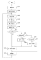
図9は、本技術の実施の形態の第4の適用例におけるまばたき検出および視線検出の処理手順例を示す流れ図である。
まず、測定対象となる人間の眼を含む画像データが取得される(ステップS871)。そのために、例えば、ウェアラブルデバイスやアイウェアデバイスを撮像部110として利用することができる。
そして、二値化処理部130において二値化処理が行われて、瞳孔領域が検出される(ステップS872)。また、トラッキング処理部140において、瞳孔の動きが追跡される(ステップS873)。
このようにして認識された瞳孔について、重心位置生成部160によってその瞳孔の重心が算出され(ステップS874)、モーメント生成部150によってモーメント演算が行われ、瞳孔の面積が算出される(ステップS875)。これにより、まばたきが検出される。また、重心位置生成部160によって生成された瞳孔の重心に基づいて、集計処理部210において視線方向が判定される(ステップS876)。例えば、ユーザが映像として30cm先の空間に浮かぶ映像を観る場合、重心位置生成部160によって生成された瞳孔の座標情報を集計処理部210が補正することなどが想定される。
その結果、左目のまばたきが検知されたと判定された場合には(ステップS881:Yes)、左クリック処理が行われる(ステップS882)。一方、右目のまばたきが検知されたと判定された場合には(ステップS883:Yes)、右クリック処理が行われる(ステップS884)。なお、両目のまばたきが検知されたと判定された場合には(ステップS877:Yes)、これらの処理は行われない。
これら何れかのまばたきが検出された場合、まばたきにより瞳孔が完全に隠れた際に、再検出のための制御が実施される(ステップS878)。そして、表示装置320において画面描画が行われる(ステップS879)。その後、ステップS873以降の処理が繰り返される。
なお、上述の適用例では瞳孔を検出してその面積を算出したが、虹彩を検出してその面積を算出するようにしてもよい。
<6.第5の適用例>
図10は、本技術の実施の形態の第5の適用例における血流速度計測の例を示す図である。ゼブラフィッシュは、コイ科の小型魚類で、最近10年において最も発展したモデル脊椎動物である。このゼブラフィッシュは、体内が透けて見えることから、脳や内臓の形成を研究するために適していることが知られている。一方、このゼブラフィッシュの血流を捉えるためには600fpsの速度を必要とする。本実施の形態における画像処理システムでは、このゼブラフィッシュの血流を高フレームレートにより撮像することにより、その観測を可能にする。
図10は、本技術の実施の形態の第5の適用例における血流速度計測の例を示す図である。ゼブラフィッシュは、コイ科の小型魚類で、最近10年において最も発展したモデル脊椎動物である。このゼブラフィッシュは、体内が透けて見えることから、脳や内臓の形成を研究するために適していることが知られている。一方、このゼブラフィッシュの血流を捉えるためには600fpsの速度を必要とする。本実施の形態における画像処理システムでは、このゼブラフィッシュの血流を高フレームレートにより撮像することにより、その観測を可能にする。
ゼブラフィッシュの血流を計測するためには、まず、撮像の対象物として、無害なカラーボールをゼブラフィッシュに飲み込ませる。そして、画像651に示すようにそのカラーボール655がフレームに出現した瞬間に、画像652に示す枠表示656と共に録画を開始する。そして、画像653に示すようにカラーボール655が流れきったところで録画を停止して、そのフレーム数から速度を求めることができる。
図11は、本技術の実施の形態の第5の適用例における血流速度計測の処理手順例を示す流れ図である。
まず、測定対象となる画像データが取得される(ステップS711)。そのために、例えば、顕微鏡を介してゼブラフィッシュの血流部分の画像を撮像部110により撮像することができる。
取得された各フレームは、フィルタ処理部120によって、一定サイズ以外のノイズが除去される(ステップS712)。また、二値化処理部130において画像データの色成分に従って二値化処理が行われる(ステップS713)。
そして、時系列に隣接するフレーム間の差分がトラッキング処理部140によって生成されて、操作入力装置310によって指定された領域内の動体が検索される(ステップS714)。ここで、動体が検出されるまで待機される(ステップS715)。
操作入力装置310によって単体がトラッキング対象として指定されると(ステップS716)、その単体についてトラッキング処理部140においてターゲットトラッキングが行われる(ステップS717)。そして、その単体について、モーメント生成部150によってモーメント演算が行われる(ステップS718)。また、その単体について、個別移動量が重心位置生成部160によって算出される(ステップS719)。このようにして得られた個別移動量は、インターフェース230を介して表示装置320に表示される(ステップS721)。
一方、操作入力装置310によって複数個体がトラッキング対象として指定されると(ステップS716)、それら複数個体についてトラッキング処理部140においてターゲットトラッキングが行われる(ステップS722)。そして、その複数個体について、モーメント生成部150によってモーメント演算が行われる(ステップS723)。また、その複数個体について、それぞれの個別移動量が重心位置生成部160によって算出される(ステップS724)。集計処理部210は、得られた個別移動量をソートして、その最大値および最小値を求める。これら個別移動量の最大値および最小値は、インターフェース230を介して表示装置320に表示される(ステップS725)。
これらの処理は、時系列に並ぶ画像データのフレームのそれぞれについて繰り返し行われる。
なお、この例では血流速度の計測および統計値の算出の例について示したが、血流速度をデータベースなどに保持された期待値と比較して、その期待値の範囲を満たさない場合には異常を検知するようにしてもよい。
<7.第6の適用例>
図12は、本技術の実施の形態の第6の適用例における振動量計測による不調検出の例を示す図である。機器の振動量を計測するために通常用いられる振動センサでは、機器に直接接続する必要があり、機器に固定するための手間を要するだけでなく、安全性についても配慮しなければならない。一方、外観を観測する場合、例えばアイドリング時に回転数が1200rpm(rotation per minute:毎分の回転数)のエンジンの1次振動の周波数は20Hz程度であるが、動作時には200Hz程度になる。本実施の形態における画像処理システムでは、機器の外観を高フレームレートにより撮像することにより、その観測を可能にする。
図12は、本技術の実施の形態の第6の適用例における振動量計測による不調検出の例を示す図である。機器の振動量を計測するために通常用いられる振動センサでは、機器に直接接続する必要があり、機器に固定するための手間を要するだけでなく、安全性についても配慮しなければならない。一方、外観を観測する場合、例えばアイドリング時に回転数が1200rpm(rotation per minute:毎分の回転数)のエンジンの1次振動の周波数は20Hz程度であるが、動作時には200Hz程度になる。本実施の形態における画像処理システムでは、機器の外観を高フレームレートにより撮像することにより、その観測を可能にする。
対象物である機器661の振動量を観測する場合、観測対象となる位置や幅を、操作入力装置310によって画像上の枠662または663のように指定する。時系列に並ぶフレームにおいて動作を観察し、領域毎の期待値と比較することにより、機器661の不調を検出することができる。
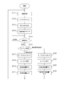
図13は、本技術の実施の形態の第6の適用例における振動量計測による不調検出の処理手順例を示す流れ図である。
まず、測定対象となる画像データが取得される(ステップS731)。そのために、例えば、撮像部110により測定対象の機器の画像が撮像される。
取得された各フレームは、フィルタ処理部120によって、ノイズが除去される(ステップS732)。また、フィルタ処理部120によって、エッジ検出が行われる(ステップS733)。そして、検出されたエッジ部分を有効とする二値化処理が二値化処理部130によって行われる(ステップS734)。
測定対象となる画像データのフレームにおいて、操作入力装置310によって観測対象となる領域が設定される(ステップS735)。その設定された領域は、制御部220からトラッキング処理部140に供給される。
トラッキング処理部140では、時系列に隣接するフレーム間の差分が生成される(ステップS736)。そして、設定された領域毎にモーメント生成部150によってモーメント演算が行われる(ステップS737)。領域毎に生成されたモーメントに基づいて、集計処理部210において領域毎の振動率が算出される(ステップS738)。
その後、操作入力装置310からの指示に従って処理が選択される(ステップS739)。振動率の出力が指示された場合は、集計処理部210において算出された領域毎の振動率がインターフェース230を介して表示装置320に表示される(ステップS741)。
振動量の期待値判定が指示されると(ステップS739)、データベースなどに保持された期待値と集計処理部210において算出された領域毎の振動率とが比較される。振動率が期待値の範囲内であれば(ステップS742:Yes)、正常であるとの判定結果がインターフェース230を介して表示装置320に表示される(ステップS743)。一方、振動率が期待値と大きく異なる場合には(ステップS742:No)、異常が発生した旨の判定結果がインターフェース230を介して表示装置320に表示される(ステップS744)。
なお、これらの処理は、時系列に並ぶ画像データのフレームのそれぞれについて繰り返し行われる。
<8.第7の適用例>
図14は、本技術の実施の形態の第7の適用例における回転量計測による不調検出の例を示す図である。ドローンや換気扇のように機器の主要部にプロペラを備える場合において、対象物であるプロペラの回転量を観測することにより不調を検出することが可能である。例えば、家庭用扇風機では強設定で1500乃至1600rpm程度、台所の換気扇で2500rpm程度である。また、ボートのスクリューはフルスロットルで5000乃至6000rpm程度、プロペラ機のプロペラは2300乃至2400rpm程度、ラジコンやドローンでは1300乃至2500rpm程度である。
図14は、本技術の実施の形態の第7の適用例における回転量計測による不調検出の例を示す図である。ドローンや換気扇のように機器の主要部にプロペラを備える場合において、対象物であるプロペラの回転量を観測することにより不調を検出することが可能である。例えば、家庭用扇風機では強設定で1500乃至1600rpm程度、台所の換気扇で2500rpm程度である。また、ボートのスクリューはフルスロットルで5000乃至6000rpm程度、プロペラ機のプロペラは2300乃至2400rpm程度、ラジコンやドローンでは1300乃至2500rpm程度である。
ボートのスクリューやプロペラ機のプロペラなどについては、内蔵のタコメータによって計測することが可能であるが、タコメータの故障もあり得るため、外側からの客観的な観測により不調を検出できることは有用である。本実施の形態における画像処理システムでは、機器の外観を高フレームレートにより撮像することにより、その観測を可能にする。
例えば、ドローン671のプロペラ部分を対象物として携帯端末672のカメラによって撮像する。その際、複数枚のプロペラのうち特定の1枚のプロペラにマーカとなるシールを貼り付けておいて、ターゲットトラッキングを行うことによりその移動量を計測することができる。また、エッジ検出を行い、それによって得られた形状についてトラッキングすることも可能である。
このようなアプリケーションを携帯端末672に搭載することにより、撮像されたプロペラ部分の回転率を、携帯端末672の表示部にリアルタイムに表示させることができる。
図15は、本技術の実施の形態の第7の適用例における回転量計測による不調検出の処理手順例を示す流れ図である。
まず、測定対象となる画像データが取得される(ステップS751)。そのために、例えば、撮像部110により測定対象の機器におけるプロペラ部分の画像が撮像される。
取得された各フレームは、フィルタ処理部120によって、ノイズが除去される(ステップS752)。そして、二値化処理部130によって色および輝度による二値化処理が行われて、プロペラ部分に貼り付けられたシールのマーカが検出される(ステップS753)。
検出されたマーカに対して画像上の領域が設定され(ステップS754)、トラッキング処理部140によってターゲットトラッキングが行われる(ステップS755)。また、設定された領域についてモーメント生成部150によってモーメント演算が行われる(ステップS756)。そして、その生成されたモーメントに基づいて、集計処理部210において回転率が算出される(ステップS757)。
その後、操作入力装置310からの指示に従って処理が選択される(ステップS758)。回転率の出力が指示された場合は、集計処理部210において算出された回転率がインターフェース230を介して表示装置320に表示される(ステップS759)。
回転率の期待値判定が指示されると(ステップS758)、データベースなどに保持された期待値と集計処理部210において算出された回転率とが比較される。回転率が期待値の範囲内であれば(ステップS761:Yes)、正常であるとの判定結果がインターフェース230を介して表示装置320に表示される(ステップS762)。一方、回転率が期待値と大きく異なる場合には(ステップS761:No)、異常が発生した旨の判定結果がインターフェース230を介して表示装置320に表示される(ステップS763)。
なお、これらの処理は、時系列に並ぶ画像データのフレームのそれぞれについて繰り返し行われる。
このように、本技術の実施の形態によれば、対象物(物体や機器)を高フレームレートにより撮像して画像センサ内で画像処理することにより、画像データを出力することなく測定結果を定量化することができる。これにより、画像解析の時間を短縮し、保持するデータストレージ量を削減することができる。また、センサレベルで演算結果を生成できるため、携帯機器を含む小型システムにおいても実現することができる。
なお、上述の実施の形態は本技術を具現化するための一例を示したものであり、実施の形態における事項と、特許請求の範囲における発明特定事項とはそれぞれ対応関係を有する。同様に、特許請求の範囲における発明特定事項と、これと同一名称を付した本技術の実施の形態における事項とはそれぞれ対応関係を有する。ただし、本技術は実施の形態に限定されるものではなく、その要旨を逸脱しない範囲において実施の形態に種々の変形を施すことにより具現化することができる。
また、上述の実施の形態において説明した処理手順は、これら一連の手順を有する方法として捉えてもよく、また、これら一連の手順をコンピュータに実行させるためのプログラム乃至そのプログラムを記憶する記録媒体として捉えてもよい。この記録媒体として、例えば、CD(Compact Disc)、MD(MiniDisc)、DVD(Digital Versatile Disc)、メモリカード、ブルーレイディスク(Blu-ray(登録商標)Disc)等を用いることができる。
なお、本明細書に記載された効果はあくまで例示であって、限定されるものではなく、また、他の効果があってもよい。
なお、本技術は以下のような構成もとることができる。
(1)対象物を撮像して時系列に並ぶ画像データのフレームを生成する撮像素子と、
前記フレームの各々に対して二値化処理を行って二値化フレームを生成する二値化処理部と、
時系列に隣接する前記二値化フレームの間の差分を生成して前記二値化フレームに含まれる前記対象物の位置の変化を追跡するトラッキング処理部と
を具備する画像センサ。
(2)前記フレームの各々に対してフィルタ処理を施すフィルタ処理部をさらに具備し、
前記二値化処理部は、前記フィルタ処理の施されたフレームの各々に対して前記二値化処理を行う
前記(1)に記載の画像センサ。
(3)前記トラッキング処理部による結果に基づいて前記二値化フレームのモーメントを算出して前記二値化フレームに含まれる前記対象物の面積の変化量を生成するモーメント生成部をさらに具備する前記(1)または(2)に記載の画像センサ。
(4)前記モーメント生成部によって生成された前記モーメントに基づいて前記二値化フレームに含まれる前記対象物の重心位置を生成する重心位置生成部をさらに具備する前記(3)に記載の画像センサ。
(5)前記重心位置生成部によって生成された前記対象物の重心位置に基づいて前記対象物に関する集計処理を行う集計処理部をさらに具備する前記(4)に記載の画像センサ。
(6)前記集計処理部による前記集計処理の結果を表示させるための表示制御部をさらに具備する前記(5)に記載の画像センサ。
(7)前記集計処理部は、前記対象物の個数、サイズ、および、運動率の少なくとも何れか一つを集計する前記(5)に記載の画像センサ。
(8)前記集計処理部は、前記対象物の形状変化を検出し、
前記トラッキング処理部は、前記対象物の形状変化が検出されると前記追跡を開始する
前記(5)に記載の画像センサ。
(9)前記集計処理部は、前記対象物の速度を計測し、前記対象物が複数ある場合にそれら対象物の速度の統計値を算出する前記(5)に記載の画像センサ。
(10)前記撮像素子は、前記対象物として生体の眼を撮像し、
前記二値化処理部は、前記撮像された生体の眼において瞳孔を検出し、
前記トラッキング処理部は、前記撮像された生体の眼における視線を追跡し、
前記モーメント生成部は、前記撮像された生体の眼における瞳孔の面積を算出し、
前記集計処理部は、前記瞳孔の面積と前記瞳孔が継続して認識されている時間とからまばたきの実施を検出する
前記(5)に記載の画像センサ。
(11)前記まばたきの実施の態様に応じて操作入力を受け付けるインターフェースをさらに具備する前記(10)に記載の画像センサ。
(12)前記重心位置生成部は、前記撮像された生体の眼における瞳孔の重心位置を生成し、
前記集計処理部は、前記瞳孔の重心位置から視線方向を判定する
前記(10)に記載の画像センサ。
(13)前記まばたきの実施の態様および前記視線方向に応じて操作入力を受け付けるインターフェースをさらに具備する前記(12)に記載の画像センサ。
(14)前記集計処理部は、前記まばたきの実施が検出されると前記瞳孔の検出を再度行うよう前記二値化処理部を制御する前記(10)に記載の画像センサ。
(15)前記集計処理部は、前記対象物の速度を計測し、前記対象物の速度が所定の条件を満たさない場合には異常を検知する前記(5)に記載の画像センサ。
(16)前記集計処理部は、前記対象物の振動量を計測し、前記対象物の振動量が所定の条件を満たさない場合には異常を検知する前記(5)に記載の画像センサ。
(17)前記集計処理部は、前記対象物の回転量を計測し、前記対象物の回転量が所定の条件を満たさない場合には異常を検知する前記(5)に記載の画像センサ。
(1)対象物を撮像して時系列に並ぶ画像データのフレームを生成する撮像素子と、
前記フレームの各々に対して二値化処理を行って二値化フレームを生成する二値化処理部と、
時系列に隣接する前記二値化フレームの間の差分を生成して前記二値化フレームに含まれる前記対象物の位置の変化を追跡するトラッキング処理部と
を具備する画像センサ。
(2)前記フレームの各々に対してフィルタ処理を施すフィルタ処理部をさらに具備し、
前記二値化処理部は、前記フィルタ処理の施されたフレームの各々に対して前記二値化処理を行う
前記(1)に記載の画像センサ。
(3)前記トラッキング処理部による結果に基づいて前記二値化フレームのモーメントを算出して前記二値化フレームに含まれる前記対象物の面積の変化量を生成するモーメント生成部をさらに具備する前記(1)または(2)に記載の画像センサ。
(4)前記モーメント生成部によって生成された前記モーメントに基づいて前記二値化フレームに含まれる前記対象物の重心位置を生成する重心位置生成部をさらに具備する前記(3)に記載の画像センサ。
(5)前記重心位置生成部によって生成された前記対象物の重心位置に基づいて前記対象物に関する集計処理を行う集計処理部をさらに具備する前記(4)に記載の画像センサ。
(6)前記集計処理部による前記集計処理の結果を表示させるための表示制御部をさらに具備する前記(5)に記載の画像センサ。
(7)前記集計処理部は、前記対象物の個数、サイズ、および、運動率の少なくとも何れか一つを集計する前記(5)に記載の画像センサ。
(8)前記集計処理部は、前記対象物の形状変化を検出し、
前記トラッキング処理部は、前記対象物の形状変化が検出されると前記追跡を開始する
前記(5)に記載の画像センサ。
(9)前記集計処理部は、前記対象物の速度を計測し、前記対象物が複数ある場合にそれら対象物の速度の統計値を算出する前記(5)に記載の画像センサ。
(10)前記撮像素子は、前記対象物として生体の眼を撮像し、
前記二値化処理部は、前記撮像された生体の眼において瞳孔を検出し、
前記トラッキング処理部は、前記撮像された生体の眼における視線を追跡し、
前記モーメント生成部は、前記撮像された生体の眼における瞳孔の面積を算出し、
前記集計処理部は、前記瞳孔の面積と前記瞳孔が継続して認識されている時間とからまばたきの実施を検出する
前記(5)に記載の画像センサ。
(11)前記まばたきの実施の態様に応じて操作入力を受け付けるインターフェースをさらに具備する前記(10)に記載の画像センサ。
(12)前記重心位置生成部は、前記撮像された生体の眼における瞳孔の重心位置を生成し、
前記集計処理部は、前記瞳孔の重心位置から視線方向を判定する
前記(10)に記載の画像センサ。
(13)前記まばたきの実施の態様および前記視線方向に応じて操作入力を受け付けるインターフェースをさらに具備する前記(12)に記載の画像センサ。
(14)前記集計処理部は、前記まばたきの実施が検出されると前記瞳孔の検出を再度行うよう前記二値化処理部を制御する前記(10)に記載の画像センサ。
(15)前記集計処理部は、前記対象物の速度を計測し、前記対象物の速度が所定の条件を満たさない場合には異常を検知する前記(5)に記載の画像センサ。
(16)前記集計処理部は、前記対象物の振動量を計測し、前記対象物の振動量が所定の条件を満たさない場合には異常を検知する前記(5)に記載の画像センサ。
(17)前記集計処理部は、前記対象物の回転量を計測し、前記対象物の回転量が所定の条件を満たさない場合には異常を検知する前記(5)に記載の画像センサ。
100 画像センサ
110 撮像部
120 フィルタ処理部
130 二値化処理部
140 トラッキング処理部
150 モーメント生成部
160 重心位置生成部
200 集計部
210 集計処理部
220 制御部
230 インターフェース
310 操作入力装置
320 表示装置
110 撮像部
120 フィルタ処理部
130 二値化処理部
140 トラッキング処理部
150 モーメント生成部
160 重心位置生成部
200 集計部
210 集計処理部
220 制御部
230 インターフェース
310 操作入力装置
320 表示装置
Claims (17)
- 対象物を撮像して時系列に並ぶ画像データのフレームを生成する撮像素子と、
前記フレームの各々に対して二値化処理を行って二値化フレームを生成する二値化処理部と、
時系列に隣接する前記二値化フレームの間の差分を生成して前記二値化フレームに含まれる前記対象物の位置の変化を追跡するトラッキング処理部と
を具備する画像センサ。 - 前記フレームの各々に対してフィルタ処理を施すフィルタ処理部をさらに具備し、
前記二値化処理部は、前記フィルタ処理の施されたフレームの各々に対して前記二値化処理を行う
請求項1記載の画像センサ。 - 前記トラッキング処理部による結果に基づいて前記二値化フレームに含まれる前記対象物のモーメントを算出するモーメント生成部をさらに具備する請求項1記載の画像センサ。
- 前記モーメント生成部によって生成された前記モーメントに基づいて前記二値化フレームに含まれる前記対象物の重心位置を生成する重心位置生成部をさらに具備する請求項3記載の画像センサ。
- 前記重心位置生成部によって生成された前記対象物の重心位置に基づいて前記対象物に関する集計処理を行う集計処理部をさらに具備する請求項4記載の画像センサ。
- 前記集計処理部による前記集計処理の結果を表示させるための表示制御部をさらに具備する請求項5記載の画像センサ。
- 前記集計処理部は、前記対象物の個数、サイズ、および、運動率の少なくとも何れか一つを集計する請求項5記載の画像センサ。
- 前記集計処理部は、前記対象物の形状変化を検出し、
前記トラッキング処理部は、前記対象物の形状変化が検出されると前記追跡を開始する
請求項5記載の画像センサ。 - 前記集計処理部は、前記対象物の速度を計測し、前記対象物が複数ある場合にそれら対象物の速度の統計値を算出する請求項5記載の画像センサ。
- 前記撮像素子は、前記対象物として生体の眼を撮像し、
前記二値化処理部は、前記撮像された生体の眼において瞳孔を検出し、
前記トラッキング処理部は、前記撮像された生体の眼における視線を追跡し、
前記モーメント生成部は、前記撮像された生体の眼における瞳孔の面積を算出し、
前記集計処理部は、前記瞳孔の面積と前記瞳孔が継続して認識されている時間とからまばたきの実施を検出する
請求項5記載の画像センサ。 - 前記まばたきの実施の態様に応じて操作入力を受け付けるインターフェースをさらに具備する請求項10記載の画像センサ。
- 前記重心位置生成部は、前記撮像された生体の眼における瞳孔の重心位置を生成し、
前記集計処理部は、前記瞳孔の重心位置から視線方向を判定する
請求項10記載の画像センサ。 - 前記まばたきの実施の態様および前記視線方向に応じて操作入力を受け付けるインターフェースをさらに具備する請求項12記載の画像センサ。
- 前記集計処理部は、前記まばたきの実施が検出されると前記瞳孔の検出を再度行うよう前記二値化処理部を制御する請求項10記載の画像センサ。
- 前記集計処理部は、前記対象物の速度を計測し、前記対象物の速度が所定の条件を満たさない場合には異常を検知する請求項5記載の画像センサ。
- 前記集計処理部は、前記対象物の振動量を計測し、前記対象物の振動量が所定の条件を満たさない場合には異常を検知する請求項5記載の画像センサ。
- 前記集計処理部は、前記対象物の回転量を計測し、前記対象物の回転量が所定の条件を満たさない場合には異常を検知する請求項5記載の画像センサ。
Priority Applications (1)
| Application Number | Priority Date | Filing Date | Title |
|---|---|---|---|
| US16/337,148 US10904429B2 (en) | 2016-12-07 | 2017-10-19 | Image sensor |
Applications Claiming Priority (2)
| Application Number | Priority Date | Filing Date | Title |
|---|---|---|---|
| JP2016-237178 | 2016-12-07 | ||
| JP2016237178A JP2018092495A (ja) | 2016-12-07 | 2016-12-07 | 画像センサ |
Publications (1)
| Publication Number | Publication Date |
|---|---|
| WO2018105248A1 true WO2018105248A1 (ja) | 2018-06-14 |
Family
ID=62490938
Family Applications (1)
| Application Number | Title | Priority Date | Filing Date |
|---|---|---|---|
| PCT/JP2017/037869 Ceased WO2018105248A1 (ja) | 2016-12-07 | 2017-10-19 | 画像センサ |
Country Status (3)
| Country | Link |
|---|---|
| US (1) | US10904429B2 (ja) |
| JP (1) | JP2018092495A (ja) |
| WO (1) | WO2018105248A1 (ja) |
Families Citing this family (4)
| Publication number | Priority date | Publication date | Assignee | Title |
|---|---|---|---|---|
| JP7023803B2 (ja) * | 2018-06-21 | 2022-02-22 | 関西電力株式会社 | 監視システム |
| JP2021096180A (ja) * | 2019-12-18 | 2021-06-24 | 日本ユニシス株式会社 | 動物の精液検査装置及び精液検査方法 |
| CN111311557A (zh) | 2020-01-23 | 2020-06-19 | 腾讯科技(深圳)有限公司 | 内窥镜图像处理方法、装置、电子设备及存储介质 |
| US12073566B2 (en) * | 2021-10-29 | 2024-08-27 | Honeywell International Inc. | System and method for vision based graphical fluid flow anomaly detection for display verification |
Citations (5)
| Publication number | Priority date | Publication date | Assignee | Title |
|---|---|---|---|---|
| JPH07129781A (ja) * | 1993-11-05 | 1995-05-19 | Ken Ishihara | 時系列画像情報抽出装置および方法 |
| JP2001076156A (ja) * | 1999-09-03 | 2001-03-23 | Mitsubishi Electric Corp | 画像監視装置 |
| JP2008287594A (ja) * | 2007-05-18 | 2008-11-27 | Nippon Hoso Kyokai <Nhk> | 特定動作判定装置、リファレンスデータ生成装置、特定動作判定プログラム及びリファレンスデータ生成プログラム |
| WO2010084902A1 (ja) * | 2009-01-22 | 2010-07-29 | 株式会社日立国際電気 | 侵入警報ビデオ処理装置 |
| JP2012238293A (ja) * | 2011-04-28 | 2012-12-06 | Nextedge Technology Inc | 入力装置 |
Family Cites Families (8)
| Publication number | Priority date | Publication date | Assignee | Title |
|---|---|---|---|---|
| JP5747695B2 (ja) | 2011-07-07 | 2015-07-15 | 富士通株式会社 | 画像処理装置、画像処理方法及び画像処理プログラム |
| JP2013169296A (ja) * | 2012-02-20 | 2013-09-02 | Canon Inc | 画像処理装置及び画像処理方法 |
| JP6334925B2 (ja) * | 2013-01-18 | 2018-05-30 | キヤノンメディカルシステムズ株式会社 | 動作情報処理装置及び方法 |
| US20160140390A1 (en) * | 2014-11-13 | 2016-05-19 | Intel Corporation | Liveness detection using progressive eyelid tracking |
| JP6651074B2 (ja) * | 2015-06-05 | 2020-02-19 | 聖 星野 | 眼球の運動を検出する方法、そのプログラム、そのプログラムの記憶媒体、及び、眼球の運動を検出する装置 |
| US9830708B1 (en) * | 2015-10-15 | 2017-11-28 | Snap Inc. | Image segmentation of a video stream |
| WO2017217177A1 (ja) * | 2016-06-17 | 2017-12-21 | ソニー株式会社 | 画像処理装置、および撮像装置、ならびに画像処理システム |
| JP7058010B2 (ja) * | 2016-09-08 | 2022-04-21 | ソニーグループ株式会社 | 演算装置およびセンサー |
-
2016
- 2016-12-07 JP JP2016237178A patent/JP2018092495A/ja active Pending
-
2017
- 2017-10-19 WO PCT/JP2017/037869 patent/WO2018105248A1/ja not_active Ceased
- 2017-10-19 US US16/337,148 patent/US10904429B2/en active Active
Patent Citations (5)
| Publication number | Priority date | Publication date | Assignee | Title |
|---|---|---|---|---|
| JPH07129781A (ja) * | 1993-11-05 | 1995-05-19 | Ken Ishihara | 時系列画像情報抽出装置および方法 |
| JP2001076156A (ja) * | 1999-09-03 | 2001-03-23 | Mitsubishi Electric Corp | 画像監視装置 |
| JP2008287594A (ja) * | 2007-05-18 | 2008-11-27 | Nippon Hoso Kyokai <Nhk> | 特定動作判定装置、リファレンスデータ生成装置、特定動作判定プログラム及びリファレンスデータ生成プログラム |
| WO2010084902A1 (ja) * | 2009-01-22 | 2010-07-29 | 株式会社日立国際電気 | 侵入警報ビデオ処理装置 |
| JP2012238293A (ja) * | 2011-04-28 | 2012-12-06 | Nextedge Technology Inc | 入力装置 |
Also Published As
| Publication number | Publication date |
|---|---|
| JP2018092495A (ja) | 2018-06-14 |
| US10904429B2 (en) | 2021-01-26 |
| US20190289202A1 (en) | 2019-09-19 |
Similar Documents
| Publication | Publication Date | Title |
|---|---|---|
| US10535160B2 (en) | Markerless augmented reality (AR) system | |
| US10282913B2 (en) | Markerless augmented reality (AR) system | |
| CN112288699B (zh) | 图像相对清晰度的评估方法、装置、设备和介质 | |
| JP2018026108A (ja) | 物体追跡方法、物体追跡装置およびプログラム | |
| WO2018105248A1 (ja) | 画像センサ | |
| JP6483168B2 (ja) | ビジョンシステムで画像内のプローブを効率的に採点するためのシステム及び方法 | |
| CN113449570A (zh) | 图像处理方法和装置 | |
| CN110866894B (zh) | 一种基于机器视觉技术的跨粒度的钣金件识别系统及方法 | |
| JPWO2018154709A1 (ja) | 動作学習装置、技能判別装置および技能判別システム | |
| JP2013065103A (ja) | 追跡装置、追跡方法およびプログラム | |
| CN108960192A (zh) | 动作识别方法及其神经网络生成方法、装置和电子设备 | |
| CN110298314A (zh) | 手势区域的识别方法及装置 | |
| JP2015032001A (ja) | 情報処理装置および情報処理手法、プログラム | |
| JP6103765B2 (ja) | 行動認識装置、方法及びプログラム並びに認識器構築装置 | |
| CN116823819A (zh) | 一种焊缝表面缺陷检测方法、系统、电子设备及存储介质 | |
| Lin et al. | Automatic sinus surgery skill assessment based on instrument segmentation and tracking in endoscopic video | |
| CN108582075A (zh) | 一种智能机器人视觉自动化抓取系统 | |
| Guan et al. | A video-based fall detection network by spatio-temporal joint-point model on edge devices | |
| JP6052533B2 (ja) | 特徴量抽出装置および特徴量抽出方法 | |
| CN108052927B (zh) | 基于视频数据的手势处理方法及装置、计算设备 | |
| CN117523659A (zh) | 基于骨架的多特征多流实时动作识别方法、装置和介质 | |
| JP2013137591A (ja) | 最近傍点探索装置およびその方法、プログラム、3次元位置・姿勢認識装置およびその方法 | |
| Rodriguez et al. | Robust vision-based hand tracking using single camera for ubiquitous 3D gesture interaction | |
| JP6764012B1 (ja) | 画像処理装置、画像処理方法、及びプログラム | |
| KR20130081126A (ko) | 손 제스처 인식 방법 및 그 장치 |
Legal Events
| Date | Code | Title | Description |
|---|---|---|---|
| 121 | Ep: the epo has been informed by wipo that ep was designated in this application |
Ref document number: 17877824 Country of ref document: EP Kind code of ref document: A1 |
|
| NENP | Non-entry into the national phase |
Ref country code: DE |
|
| 122 | Ep: pct application non-entry in european phase |
Ref document number: 17877824 Country of ref document: EP Kind code of ref document: A1 |