WO2018105239A1 - センシングシステム、および、センサデバイス - Google Patents
センシングシステム、および、センサデバイス Download PDFInfo
- Publication number
- WO2018105239A1 WO2018105239A1 PCT/JP2017/037462 JP2017037462W WO2018105239A1 WO 2018105239 A1 WO2018105239 A1 WO 2018105239A1 JP 2017037462 W JP2017037462 W JP 2017037462W WO 2018105239 A1 WO2018105239 A1 WO 2018105239A1
- Authority
- WO
- WIPO (PCT)
- Prior art keywords
- sensor
- signal
- trigger
- sensing system
- time data
- Prior art date
- Legal status (The legal status is an assumption and is not a legal conclusion. Google has not performed a legal analysis and makes no representation as to the accuracy of the status listed.)
- Ceased
Links
Images










Classifications
-
- G—PHYSICS
- G04—HOROLOGY
- G04F—TIME-INTERVAL MEASURING
- G04F10/00—Apparatus for measuring unknown time intervals by electric means
-
- G—PHYSICS
- G08—SIGNALLING
- G08C—TRANSMISSION SYSTEMS FOR MEASURED VALUES, CONTROL OR SIMILAR SIGNALS
- G08C15/00—Arrangements characterised by the use of multiplexing for the transmission of a plurality of signals over a common path
- G08C15/06—Arrangements characterised by the use of multiplexing for the transmission of a plurality of signals over a common path successively, i.e. using time division
-
- G—PHYSICS
- G01—MEASURING; TESTING
- G01D—MEASURING NOT SPECIALLY ADAPTED FOR A SPECIFIC VARIABLE; ARRANGEMENTS FOR MEASURING TWO OR MORE VARIABLES NOT COVERED IN A SINGLE OTHER SUBCLASS; TARIFF METERING APPARATUS; MEASURING OR TESTING NOT OTHERWISE PROVIDED FOR
- G01D9/00—Recording measured values
-
- G—PHYSICS
- G04—HOROLOGY
- G04C—ELECTROMECHANICAL CLOCKS OR WATCHES
- G04C9/00—Electrically-actuated devices for setting the time-indicating means
-
- G—PHYSICS
- G04—HOROLOGY
- G04F—TIME-INTERVAL MEASURING
- G04F10/00—Apparatus for measuring unknown time intervals by electric means
- G04F10/04—Apparatus for measuring unknown time intervals by electric means by counting pulses or half-cycles of an AC
-
- G—PHYSICS
- G04—HOROLOGY
- G04G—ELECTRONIC TIME-PIECES
- G04G21/00—Input or output devices integrated in time-pieces
- G04G21/02—Detectors of external physical values, e.g. temperature
-
- G—PHYSICS
- G04—HOROLOGY
- G04G—ELECTRONIC TIME-PIECES
- G04G5/00—Setting, i.e. correcting or changing, the time-indication
-
- G—PHYSICS
- G04—HOROLOGY
- G04R—RADIO-CONTROLLED TIME-PIECES
- G04R20/00—Setting the time according to the time information carried or implied by the radio signal
- G04R20/02—Setting the time according to the time information carried or implied by the radio signal the radio signal being sent by a satellite, e.g. GPS
-
- G—PHYSICS
- G04—HOROLOGY
- G04R—RADIO-CONTROLLED TIME-PIECES
- G04R20/00—Setting the time according to the time information carried or implied by the radio signal
- G04R20/08—Setting the time according to the time information carried or implied by the radio signal the radio signal being broadcast from a long-wave call sign, e.g. DCF77, JJY40, JJY60, MSF60 or WWVB
-
- G—PHYSICS
- G08—SIGNALLING
- G08C—TRANSMISSION SYSTEMS FOR MEASURED VALUES, CONTROL OR SIMILAR SIGNALS
- G08C17/00—Arrangements for transmitting signals characterised by the use of a wireless electrical link
-
- G—PHYSICS
- G08—SIGNALLING
- G08C—TRANSMISSION SYSTEMS FOR MEASURED VALUES, CONTROL OR SIMILAR SIGNALS
- G08C19/00—Electric signal transmission systems
-
- G—PHYSICS
- G08—SIGNALLING
- G08C—TRANSMISSION SYSTEMS FOR MEASURED VALUES, CONTROL OR SIMILAR SIGNALS
- G08C19/00—Electric signal transmission systems
- G08C19/16—Electric signal transmission systems in which transmission is by pulses
- G08C19/26—Electric signal transmission systems in which transmission is by pulses by varying pulse repetition frequency
-
- G—PHYSICS
- G06—COMPUTING OR CALCULATING; COUNTING
- G06F—ELECTRIC DIGITAL DATA PROCESSING
- G06F1/00—Details not covered by groups G06F3/00 - G06F13/00 and G06F21/00
- G06F1/16—Constructional details or arrangements
- G06F1/1613—Constructional details or arrangements for portable computers
- G06F1/163—Wearable computers, e.g. on a belt
Definitions
- This technology relates to sensing systems and sensor devices. Specifically, the present invention relates to a sensing system in which a plurality of sensor devices perform measurement, and the sensor device.
- IoT Internet of Things
- a host computer wirelessly transmits a command to synchronize time to a plurality of communication devices, and these communication devices synchronize time according to the command before starting measurement of vibration (for example, Patent Document 1). reference.).
- the host computer can synchronize the measurement timing of each communication device by wirelessly transmitting a command.
- This technology has been created in view of such a situation, and aims to synchronize measurement timing with a simple configuration in a system in which a plurality of devices perform measurement.
- the present technology has been made to solve the above-described problems.
- the first aspect of the present technology is that a trigger sensor that measures a signal value of a trigger signal and the measured signal value satisfy a predetermined condition.
- a sensing system including a plurality of sensor devices each including a target sensor that starts measurement of a physical quantity to be measured. As a result, the physical quantity measurement is started when the signal value of the trigger signal satisfies a predetermined condition.
- the first sensor device may further include a timer that starts timing when the signal value measured by the trigger sensor satisfies the predetermined condition. Good. This brings about the effect that time measurement is started when the signal value of the trigger signal satisfies a predetermined condition.
- the timer may correct the time based on the signal value after starting the time measurement. As a result, the time is corrected based on the signal value.
- the timer may be initialized to a predetermined initial value when the signal value satisfies the predetermined condition. Thereby, when a predetermined condition is satisfied, the time is started from the initial value.
- the sensor device holds a timer that measures time data, and the time data when the signal value satisfies a predetermined condition as start time data, and the start time data And a time data processing unit for generating sensor time data from the difference between the time data and the time data. This brings about the effect that the time data for the sensor is generated separately from the time data of the timer.
- the sensor device may include a plurality of sensors that measure different physical quantities as the target sensor. This brings about the effect that a plurality of different physical quantities are measured.
- the sensor device may include a plurality of sensors that measure different signals as the trigger sensor. Accordingly, there is an effect that time measurement is started when signal values of a plurality of different signals satisfy a predetermined condition.
- the target sensor measures the physical quantity in synchronization with a sampling clock having a predetermined frequency
- the trigger sensor synchronizes with the sampling clock having a frequency higher than the predetermined frequency. May be measured.
- the signal value is measured in synchronization with a sampling clock having a frequency higher than that of the first target sensor.
- the trigger signal may include at least one of an audio signal and an optical signal. This brings about the effect that the measurement of the first and second physical quantities is started when the signal value of at least one of the audio signal and the optical signal satisfies a predetermined condition.
- the target sensor may be an image sensor.
- the trigger sensor may be an image sensor.
- the physical quantity measurement is started when the image data satisfies a predetermined condition.
- a second aspect of the present technology includes a trigger sensor that measures a signal value of a trigger signal, a target sensor that starts measurement of a physical quantity to be measured when the measured signal value satisfies a predetermined condition, Is a sensor device. This brings about the effect that the measurement of the physical quantity to be measured is started when the signal value of the trigger signal satisfies the predetermined condition.
- the present technology in a system in which a plurality of devices perform measurement, it is possible to achieve an excellent effect that the measurement timing can be synchronized with a simple configuration.
- the effects described here are not necessarily limited, and may be any of the effects described in the present disclosure.
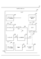
- 1 is an overall diagram illustrating a configuration example of a sensing system according to a first embodiment of the present technology.
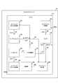
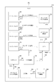
- 1 is a block diagram illustrating a configuration example of a wearable device according to a first embodiment of the present technology. It is a block diagram showing an example of 1 composition of wearable device which time-synchronizes with a real time clock in a 1st embodiment of this art. It is a figure showing an example of data recorded on a recording part in a 1st embodiment of this art.
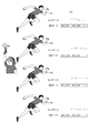
- 6 is a timing chart illustrating an example of the operation of the wearable device according to the first embodiment of the present technology. It is a figure for demonstrating the utilization method of the sensing system in 1st Embodiment of this technique.
- FIG 3 is a timing chart illustrating an example of an operation of the sensing system according to the first embodiment of the present technology.
- 7 is a flowchart illustrating an example of the operation of the wearable device according to the first embodiment of the present technology. It is a figure showing an example of 1 composition of a sensing system in the 1st modification of a 1st embodiment of this art. It is a figure showing an example of 1 composition of a sensing system in the 2nd modification of a 1st embodiment of this art. It is a block diagram showing an example of 1 composition of a wearable device in the 3rd modification of a 1st embodiment of this art.
- FIG. 1 is an overall view illustrating a configuration example of the sensing system 100 according to the first embodiment of the present technology.
- the sensing system 100 includes wearable devices 101, 102, 103 and 104. In this example, four wearable devices 101 to 104 are assumed, but the number of wearable devices in the sensing system 100 is not limited to four.
- Wearable device 101 is a device having a shape that can be worn on the body, such as a wristband type.
- the wearable device 101 measures the signal value of the trigger signal, and starts measuring the physical quantity to be measured when the signal value satisfies a predetermined condition.
- the trigger signal is a signal used to start measurement of a physical quantity, and for example, an audio signal or an optical signal is used.
- physical quantities for example, acceleration, angular velocity, pulse and temperature are measured.
- the configuration of wearable devices 102, 103, and 104 is the same as that of wearable device 101.
- the wearable device 101 is an example of the 1st sensor device as described in a claim
- the wearable device 102 is an example of the 2nd sensor device as described in a claim.
- These wearable devices 101, 102, 103, and 104 are attached to different runners on a one-to-one basis, and are used for measuring the acceleration of each runner.
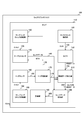
- FIG. 2 is a block diagram illustrating a configuration example of the wearable device 101 according to the first embodiment of the present technology.
- the wearable device 101 includes a chip 110.
- the chip 110 is provided with a sampling clock supply unit 120, a timer clock supply unit 130, a target sensor 140, a timer 150, a trigger sensor 160, a trigger determination unit 170, and a sampling clock supply unit 180. Further, the chip 110 is provided with a recording unit 190 and a sensor data collection unit 200. Each of the circuits in the chip 110 operates in synchronization with the main clock CLKm.
- the sampling clock supply unit 180 generates a sampling clock CLKs1 having a predetermined frequency and supplies it to the trigger sensor 160 via the signal line 189.
- the sampling clock CLKs1 is generated by a crystal oscillator, a phase synchronization circuit, a frequency divider, or the like.
- the frequency of the sampling clock CLKs1 is assumed to be lower than the main clock CLKm.
- the trigger sensor 160 measures the signal value of the trigger signal in synchronization with the sampling clock CLKs1.
- “measurement” means that the measurement object is replaced with a numerical value or a sign.
- the trigger sensor 160 converts (that is, measures) the trigger signal to be measured into sensor data indicating the signal value, and transmits the sensor data to the trigger determination unit 170 via the signal line 169.
- a microphone is used as the trigger sensor 160.
- an optical sensor is used as the trigger sensor 160.
- the trigger determination unit 170 determines whether or not the signal value of the trigger signal satisfies a predetermined condition. For example, the trigger determination unit 170 compares the signal value with a predetermined threshold, and determines that the condition is satisfied when the signal value exceeds the threshold. When the condition is satisfied, the trigger determination unit 170 generates an activation signal STA for starting measurement and a reset signal RST for initializing time data. Then, the trigger determination unit 170 supplies the activation signal STA to the sampling clock supply unit 120 and the target sensor 140 via the signal line 178, and supplies the reset signal RST to the timer 150 via the signal line 179. By transmitting the reset signal RST at the same time as the activation signal STA, the wearable device 101 can simultaneously perform measurement timing synchronization and time synchronization.
- the trigger determination unit 170 compares the signal value with a threshold value and determines that the condition is satisfied when the threshold value is exceeded.
- the determination method for determining whether or not the condition is satisfied is limited to comparison with the threshold value.
- the trigger determination unit 170 may compare data consisting of a predetermined number of signal values with a certain signal pattern (such as an audio pattern), and may determine that the condition is satisfied if it substantially matches the pattern.
- the sampling clock supply unit 120 starts generating the sampling clock CLKs2 when the activation signal STA is input, and supplies the sampling clock CLKs2 to the target sensor 140 via the signal line 129.
- the frequency of the sampling clock CLKs1 used for measurement of the trigger signal is higher than that of the sampling clock CLKs2 used for measurement of acceleration and the like.
- a clock of 16 kilohertz (kHz) is used as the sampling clock CLKs1
- a clock of 100 hertz (Hz) is used as the sampling clock CLKs2.
- the target sensor 140 starts measuring physical quantities (acceleration, etc.) when the activation signal STA is input.
- the target sensor 140 performs measurement in synchronization with the sampling clock CLKs2, and generates sensor data indicating the measurement value. Then, the target sensor 140 supplies the sensor data to the sensor data collection unit 200 via the signal line 149.
- the timer clock supply unit 130 supplies a timer clock CLKt having a predetermined frequency to the timer 150 via the signal line 139.
- the frequency of the timer clock CLKt is assumed to be lower than that of the main clock CLKm.
- a clock having a frequency of 32.768 kilohertz (kHz) is used as the timer clock CLKt.
- the timer 150 measures time in synchronization with the timer clock CLKt, and generates time data indicating the time.
- the timer 150 sets time data to a predetermined initial value.
- the timer 150 supplies time data to the sensor data collection unit 200 via the signal line 159.
- the sensor data collection unit 200 stores the sensor data in the recording unit 190 in association with time data when the sensor data is measured.
- the recording unit 190 records sensor data and time data.
- the wearable device 101 records sensor data and time data, but may transmit these data to the outside wirelessly or by wire.
- the chip 110 is provided in the wearable device, the chip 110 may be provided in a device other than the wearable device as long as it is a device that measures a physical quantity.
- the chip 110 can be provided in a mobile device or a stationary device.
- the timer 150 measures time using the timer clock CLKt synchronized with the main clock CLKm. However, as illustrated in FIG. 3, the timer 150 performs time measurement using the timer clock synchronized with the CLK RTC from the real time clock. May be.
- the real-time clock is a circuit that keeps timing by the battery even when the power of the device is off, and supplies a clock RTC of 32.768 hertz (Hz), for example.
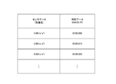
- FIG. 3 is a diagram illustrating an example of data recorded in the recording unit 190 according to the first embodiment of the present technology. For example, it is assumed that acceleration is measured as sensor data, and time in “HH: SS: fff” format is measured as time data. Here, “HH” indicates minutes, “SS” indicates seconds, and “fff” indicates milliseconds.
- the time data is initialized to, for example, “00: 00: 000” and, for example, “5.88” meters per second (m / s 2 ) is measured as the first acceleration.
- the sampling clock CLKs2 is 100 hertz (Hz)
- at “00: 00: 010” after 0.01 second for example, “5.80” meters per second per second (m / s 2 ) is measured as the next acceleration.
- the sensor data collection unit 200 stores the time data “00: 00: 000” and the sensor data “5.88” in association with each other in the recording unit 190, and the time “00: 00: 010”.
- the data and the sensor data “5.80” are stored in the recording unit 190 in association with each other.
- FIG. 4 is a timing chart illustrating an example of the operation of the wearable device 101 according to the first embodiment of the present technology.
- the main clock CLKm is input to the chip 110.
- the trigger sensor 160 measures the signal value of the trigger signal in synchronization with the sampling clock CLKs1.
- the trigger determination unit 170 determines whether or not the signal value exceeds the threshold in synchronization with the main clock CLKm from the rising timing T0 of the sampling clock CLKs1 until the trigger determination period elapses.
- the length of the trigger determination period is set to a value longer than the cycle of the main clock CLKm and shorter than the cycle of the sampling clock CLKs1. With this setting, the accuracy of synchronization depends only on the period of the sampling clock CLKs1 and the phase difference between devices of that clock. It is assumed that the signal value does not exceed the threshold during the trigger determination period from timing T0. In this case, the activation signal STA is not output.
- the timer 150 measures time in synchronization with the timer clock CLKt.
- the timer clock CLKt for convenience of description, only the millisecond portion is described as the time data value.
- the activation signal STA is output at timing T2 when the trigger determination period has elapsed.
- the target sensor 140 starts measuring acceleration and the like in synchronization with the sampling clock CLKs2.
- the trigger determination unit 170 initializes time data with the reset signal RST at the timing T2.
- FIG. 5 is a diagram for describing a method of using the sensing system according to the first embodiment of the present technology.
- This sensing system 100 is used when measuring the acceleration of each of a plurality of runners in athletics such as short-distance running. Wearable devices 101 to 104 in sensing system 100 are attached to each runner. An audio signal is used as a trigger signal. Then, the threshold value to be compared with the signal value of the trigger signal is set to a value that is less than the volume when the starter pistol 501 is sounded.
- each of the runners starts to accelerate.
- each of the wearable devices 101 to 104 starts measuring acceleration and initializes time data to measure time.
- each of the wearable devices 101 to 104 starts measuring the acceleration according to the audio signal, so that the measurement timing of each device can be synchronized.
- a host computer can be provided, and the host computer can send commands via the network to synchronize the timing.
- this configuration increases the scale and cost of the system by the amount of the host computer. .
- each of the wearable devices 101 to 104 starts measurement in response to a trigger signal (such as an audio signal)
- a trigger signal such as an audio signal
- an optical signal may be used as the trigger signal instead of the audio signal.
- an optical signal can be used as a trigger signal. Since the speed of light is faster than that of sound, if the optical signal is used as a trigger signal, the arrival time of the trigger signal to the device can be shortened and the synchronization accuracy can be improved.
- a signal other than an audio signal or an optical signal can be used as the trigger signal.
- FIG. 6 is a timing chart showing an example of the operation of the sensing system according to the first embodiment of the present technology.
- the black circles in the figure indicate the timing when the trigger sensor 160 is measured.
- a white circle indicates the timing when the target sensor 140 starts measurement.
- the sampling clock CLKs1 to each trigger sensor 160 of the wearable devices 101 to 104 is not synchronized. For this reason, the timing at which each of the wearable devices 101 to 104 starts measurement is not strictly the same.
- the maximum value of the synchronization timing shift is the value of the period of the sampling clock CLKs1.
- the measurement is started in each device between the timing T11 and the period of the sampling clock CLKs1.
- the wearable device 104 starts measurement at timing T11
- the wearable device 103 starts measurement at timing T12.
- the other devices start measurement between timings T11 and T12.
- the frequency of the sampling clock CLKs1 is 16 kilohertz (kHz), the period is 62.5 microseconds ( ⁇ s).
- the deviation of the timing of other devices with respect to the reference is a maximum of ⁇ 62.5 microseconds ( ⁇ s).
- the code indicates whether the timing is delayed or advanced with respect to the reference timing. Further, if the frequency of the sampling clock CLKs1 is set to 1 megahertz (MHz), the timing shift can be suppressed to ⁇ 1 microsecond ( ⁇ s) at the maximum.
- the timing deviation varies from ⁇ 1 microsecond ( ⁇ s) to ⁇ 100 microsecond ( ⁇ s) depending on the time required for calculating the algorithm for processing the packet and transmission delay It will be about.
- each device receives radio waves from GPS (Global Positioning System) satellites, acquires the time from the received data, and synchronizes.
- GPS Global Positioning System
- the timing deviation is ⁇ 1 microsecond at the maximum. ( ⁇ s).
- each device has a built-in radio clock that receives the standard radio wave and corrects the time, and in this configuration, the maximum timing deviation is about ⁇ 10 milliseconds (ms). Become.
- the amount of synchronization timing shift can be made the same or smaller. Further, the scale and cost of the system can be reduced as compared with a method in which a host computer is provided.
- the method of receiving radio waves from GPS satellites cannot be used indoors, the sensing system 100 can also be used indoors. Further, in the method incorporating the radio timepiece, time in minutes is required for time correction, but in the sensing system 100, the timing can be synchronized in a shorter time.
- FIG. 7 is a flowchart illustrating an example of the operation of the wearable device 101 according to the first embodiment of the present technology. This operation is started, for example, when the wearable device 101 is turned on or when a predetermined application is executed.
- the wearable device 101 initializes time data and starts measuring time (step S901). Wearable device 101 starts measurement by trigger sensor 160 (Step S902). Then, wearable device 101 determines whether or not the signal value of the trigger signal has exceeded the threshold value (step S903). When the signal value does not exceed the threshold value (step S903: No), the wearable device 101 repeats step S903.
- step S903: Yes when the signal value exceeds the threshold value (step S903: Yes), the wearable device 101 initializes the time data and continues timing (step S904), and starts measurement by the target sensor 140 (step S905). . Then, wearable device 101 determines whether the end of measurement is instructed by a user's predetermined switch operation or the like (step S906). When the termination is not instructed (step S906: No), the wearable device 101 continues the measurement and repeats step S906. On the other hand, when the end is instructed (step S906: Yes), the wearable device 101 ends the operation for measurement.
- the wearable devices 101 to 104 start measurement when the value of the trigger signal satisfies a predetermined condition.
- the timing of each measurement can be synchronized.
- the wearable device 101 or the like is provided with the chip 110 for use in athletics.
- the surveillance camera may be provided with the chip 110 for use in monitoring or crime prevention.
- the system of the first modification example in the first embodiment is different from the first embodiment in that the timing of each measurement of a plurality of surveillance cameras is synchronized.
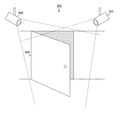
- FIG. 8 is a diagram illustrating a configuration example of the sensing system 100 in the first modified example of the first embodiment of the present technology.
- a sensing system 100 according to a first modification of the first embodiment includes monitoring cameras 300 and 301.
- the monitoring camera 300 includes the same chip 110 as that in the first embodiment. However, an image sensor is used as the target sensor 140.
- the trigger determination unit 170 in the monitoring camera 300 compares the sound pattern when the door is opened and the sound data composed of the signal value of the trigger signal (sound signal). ) Is supplied with an activation signal STA.
- the image sensor starts measuring the amount of received light for each pixel (in other words, capturing image data) in response to the activation signal STA.
- the configuration of the monitoring camera 301 is the same as that of the monitoring camera 300.
- each of the monitoring cameras is connected to the host computer via a wireless or wired network, and is synchronized according to a command transmitted from the host computer.
- the sensing system 100 using an audio signal as a trigger signal it is not necessary to construct a network and a host computer is unnecessary. Accordingly, the scale and cost of the system can be reduced accordingly.
- the monitoring cameras 300 and 301 since the monitoring cameras 300 and 301 start imaging when the value of the trigger signal satisfies the predetermined condition, no host computer is provided. In addition, the imaging timing of each surveillance camera can be synchronized.
- the wearer wears the wearable device 101 and the like for use in athletics, but it can also be used for orchestral recording by wearing the wearable device 101 and the like for a musical instrument or player.
- the system of the second modification example in the first embodiment is different from the first embodiment in that the timing of each measurement of the device attached to the musical instrument or the player is synchronized.
- FIG. 9 is a diagram illustrating a configuration example of the sensing system 100 in the second modification example of the first embodiment of the present technology.
- each of the wearable devices 101 to 104 is attached to a musical instrument or a player.
- An optical signal is used as the trigger signal
- an image sensor is used as the trigger sensor 160.
- a microphone is used as the target sensor 140.
- the trigger determination unit 170 analyzes the image data captured by the image sensor and recognizes a gesture when the conductor signals the start of performance. Then, the trigger determination unit 170 determines that the condition is satisfied when the recognition is successful, and causes the target sensor 140 to start measuring the voice. The measured sound is recorded (that is, recorded) in the recording unit 190.
- a plurality of microphones are connected to a recorder wirelessly or by wire, and audio data from these microphones is recorded in synchronization with the recorder.
- the system configuration can be simplified.
- each device since the wearable device 101 and the like start recording when the value of the trigger signal satisfies a predetermined condition, each device has a simple configuration. The timing of recording can be synchronized.
- the time data of the timer 150 is initialized. However, when this time data is used as the internal clock of the chip 110, it is desirable not to change this time data.
- the third modification of the first embodiment is different from the first embodiment in that the time data for the sensor is generated separately without initializing the time data of the timer 150.
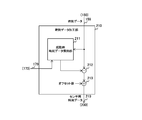
- FIG. 11 is a block diagram illustrating a configuration example of the wearable device 101 according to the third modification example of the first embodiment of the present technology.
- the wearable device 101 of the third modification is different from the first embodiment in that it further includes a time data processing unit 210.
- the timer 150 may measure time using a timer clock synchronized with the CLK RTC from the real-time clock.
- FIG. 12 is a block diagram illustrating a configuration example of the time data processing unit 210 in the third modification example of the first embodiment of the present technology.
- the time data processing unit 210 includes a startup time data holding unit 211 and a subtracter 212.
- the activation time data holding unit 211 holds the time data when the reset signal RST from the trigger determination unit 170 rises as activation time data.
- the startup time data holding unit 211 supplies the startup time data to the subtractor 212. Note that the time data measured by the timer 150 is not initialized, and is used as an internal clock in the chip 110, for example.
- the subtractor 212 calculates a difference between the time data at startup and the time data from the timer 150.
- the subtractor 212 supplies the difference time data to the sensor data collection unit 200 as sensor time data.
- FIG. 13 is a timing chart illustrating an example of a time measuring operation in the third modification example of the first embodiment of the present technology.
- the time data holding unit 211 holds the time data at that time (for example, “930”) as activation time data.
- the subtractor 212 outputs the difference between the start time data and the time data of the timer 150 as sensor time data.
- the difference (sensor time data) is “000”.
- the time data of the timer 150 is updated to “931” at the timing T2
- the sensor time data is also updated to “001”.
- the time data processing unit 210 may further include an adder 213 that adds a predetermined offset value to the difference. For example, when only the minute, second, and millisecond are initialized at startup and the date and time are used as they are, the date and time are added as an offset value.
- the time data of the timer 150 is not initialized at the time of start-up and the sensor time data is generated separately. Can be used as an internal clock.
- each of the wearable devices 101 to 104 is mounted on different runners on a one-to-one basis.
- all of these devices can be mounted on a single runner.
- a single runner is equipped with a plurality of devices that measure different physical quantities, a plurality of physical quantities can be measured simultaneously.
- the sensing system 100 of the second embodiment differs from the first embodiment in that a plurality of physical quantities are measured simultaneously for one runner.
- FIG. 15 is a diagram illustrating a configuration example of the sensing system 100 according to the second embodiment of the present technology.
- the wearable devices 101 to 104 are attached to one runner. Further, each of the wearable devices 101 to 104 measures different physical quantities according to the trigger signal. For example, the wearable device 101 measures acceleration, and the wearable device 102 measures angular velocity.
- the wearable device 103 measures a pulse, and the wearable device 104 measures a temperature. Thereby, the sensing system 100 can simultaneously start measuring a plurality of different physical quantities.
- the wearable device 101 and the like measure a plurality of physical quantities that are different from each other according to the trigger signal, so that the timings of the measurement of the plurality of physical quantities can be synchronized.
- one type of signal (for example, only an audio signal) is used as a trigger signal in the sensing system 100.
- the start may be signaled by other types of signals, and the timing cannot be synchronized in such a tournament.
- a device using another type for example, an optical signal
- the wearable device 101 or the like uses a plurality of types of signals as trigger signals, for example, it is possible to cope with either a sound signal or an optical signal as a start signal.
- the sensing system 100 according to the third embodiment is different from the first embodiment in that an audio signal and an optical signal are used as trigger signals.
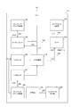
- FIG. 16 is a diagram illustrating a configuration example of the wearable device 101 according to the third embodiment of the present technology.
- This wearable device 101 is different from the first embodiment in that it further includes a trigger sensor 161.
- the trigger sensor 161 measures a signal value different from that of the trigger sensor 160.
- the trigger sensor 160 measures the value of the audio signal
- the trigger sensor 161 measures the value of the optical signal.
- the trigger sensor 160 is supplied with a sampling clock CLKs0, and the trigger sensor 161 is supplied with a sampling clock CLKs1.
- the trigger determination unit 170 determines whether or not the signal values of the audio signal and the optical signal satisfy a predetermined condition. For example, when the value of the audio signal is greater than the threshold value Th1, or when the value of the optical signal is greater than the threshold value Th2, the trigger determination unit 170 determines that the condition is satisfied and generates the activation signal STA. Thereby, it is possible to cope with both the case where only the audio signal is used for the start signal and the case where only the optical signal is used for the start signal, and the versatility of the sensing system 100 can be improved.
- the trigger determination unit 170 may determine that the condition is satisfied when the value of the audio signal is greater than the threshold value Th1 and the value of the optical signal is greater than the threshold value Th2.
- the sensing system 100 uses two signals, an audio signal and an optical signal, as trigger signals, but three or more signals may be used as trigger signals. Furthermore, the sensing system 100 may use a plurality of signals other than audio signals and optical signals as trigger signals.
- the wearable device 101 and the like measure the value of the optical signal in addition to the audio signal, and therefore, the versatility of the system compared to the case of measuring only the audio signal. And reliability can be improved.
- one physical quantity is measured by wearing one wearable device for each runner.
- each wearable device measures a plurality of physical quantities.
- the sensing system 100 according to the fourth embodiment is different from the first embodiment in that one wearable device measures a plurality of physical quantities.
- FIG. 17 is a diagram illustrating a configuration example of the wearable device 101 according to the fourth embodiment of the present technology.
- This wearable device 101 is different from the first embodiment in that it further includes target sensors 141, 142, and 143.
- the target sensors 140, 141, 142, and 143 measure different physical quantities.
- the target sensor 140 measures acceleration
- the target sensor 141 measures angular velocity
- the target sensor 142 measures the pulse
- the target sensor 143 measures the temperature.
- the trigger determination unit 170 also supplies the activation signal to the target sensors 141, 142, and 143.
- the sampling clock supply unit 120 supplies sampling clocks CLKs3, CLKs4, and CLKs5 to the target sensors 141, 142, and 143.
- the sensor data collection unit 200 records the sensor data from each of the target sensors 141, 142, and 143 in the recording unit 190 in association with the time data.
- the configuration of wearable devices 102, 103, and 104 is the same as that of wearable device 101.
- the number of wearable devices is not limited to four. For example, when there is only one runner, only the wearable device 101 is provided.
- the wearable device 101 that measures a plurality of physical quantities is attached to each of a plurality of runners, and thus the sensing system 100 measures a plurality of physical quantities for each runner. be able to.
- FIG. 18 is an overall view illustrating a configuration example of the sensing system 100 according to the fifth embodiment of the present technology.
- a speaker 502 is further arranged in the sensing system 100 of the fifth embodiment.
- the speaker 502 is connected to the starter pistol 501 by wire or wirelessly.
- the speaker 502 periodically outputs an audio signal after the starter pistol 501 generates an audio signal.
- the audio signal output from the speaker 502 is an audio signal in a high frequency band (for example, 20 kHz or more) that cannot be heard by humans so as not to reduce the concentration of the runner.
- Each of the wearable devices 101 etc. corrects the time according to the audio signal in the high frequency band.
- the speaker 502 outputs an audio signal every M (M is a real number) seconds.
- the trigger determination unit 170 in the wearable device 101 repeatedly measures the signal value of the audio signal in the high frequency band in synchronization with the sampling clock CLKs1 after the start of time measurement. Each time the trigger determination unit 170 determines that the signal value is higher than the threshold value, the trigger determination unit 170 counts the determined number, and transmits a control signal corresponding to the count value to the timer 150. For example, when the number of times is N (N is an integer), the trigger determination unit 170 transmits a control signal for correcting the time data to M ⁇ N seconds.
- a light-emitting device that periodically uses an optical signal as a trigger signal and emits the optical signal instead of the speaker 502 may be arranged, and the wearable device 101 or the like may correct the time according to the optical signal.
- the optical signal emitted from the light emitting device is invisible light such as infrared light so as not to reduce the concentration of the runner.
- an audio signal may be used for a start signal and an optical signal may be used for correction.
- a plurality of trigger sensors may be provided in the wearable device 101 as in the third embodiment.
- FIG. 19 is a timing chart showing the operation of the sensing system 100 when correcting the time according to the fifth embodiment of the present technology.
- each of the wearable devices 101 to 104 initializes time data and starts measuring sensor data (acceleration, etc.).
- sensor data acceleration, etc.
- each of the wearable devices 101 to 104 corrects the time data to 0.1 seconds (that is, 100 milliseconds).
- the speaker 502 outputs a second audio signal. Based on the audio signal, each of the wearable devices 101 to 104 corrects the time data to 0.2 seconds (that is, 200 milliseconds). Similarly, the speaker 502 outputs the Nth audio signal every 0.1 seconds, and the wearable device 101 or the like corrects the time data to N ⁇ 0.1 seconds each time.
- the wearable device 101 corrects the time data based on the audio signal after the start of time measurement, so that each device can time the correct time.
- IoT Internet of things
- IoT Internet of things
- IoT devices 9100 which are “things”
- IoT devices 9003 the Internet, the cloud 9005, and the like and control each other by exchanging information.
- IoT can be used in various industries such as agriculture, homes, automobiles, manufacturing, distribution, and energy.
- FIG. 20 is a diagram illustrating an example of a schematic configuration of an IoT system 9000 to which the technology according to the present disclosure can be applied.
- the IoT device 9001 includes various sensors such as a temperature sensor, a humidity sensor, an illuminance sensor, an acceleration sensor, a distance sensor, an image sensor, a gas sensor, and a human sensor. Further, the IoT device 9001 may include a terminal such as a smartphone, a mobile phone, a wearable terminal, or a game device.
- the IoT device 9001 is powered by an AC power source, a DC power source, a battery, non-contact power feeding, so-called energy harvesting, or the like.
- the IoT device 9001 can communicate by wired, wireless, proximity wireless communication, and the like.
- 3G / LTE, WiFi, IEEE 802.15.4, Bluetooth, Zigbee (registered trademark), Z-Wave, or the like is preferably used.
- the IoT device 9001 may perform communication by switching a plurality of these communication means.
- the IoT device 9001 may form a one-to-one, star, tree, or mesh network.
- the IoT device 9001 may be connected to an external cloud 9005 directly or through a gateway 9002.
- An address is assigned to the IoT device 9001 by IPv4, IPv6, 6LoWPAN, or the like.
- Data collected from the IoT device 9001 is transmitted to other IoT devices 9003, a server 9004, a cloud 9005, and the like.
- the timing and frequency at which data is transmitted from the IoT device 9001 are suitably adjusted, and the data may be compressed and transmitted.
- Such data may be used as it is, or the data may be analyzed by the computer 9008 by various means such as statistical analysis, machine learning, data mining, cluster analysis, discriminant analysis, combination analysis, and time series analysis.
- various services such as control, warning, monitoring, visualization, automation, and optimization can be provided.
- IoT device 9001 at home includes washing machine, dryer, dryer, microwave oven, dishwasher, refrigerator, oven, rice cooker, cooking utensil, gas appliance, fire alarm, thermostat, air conditioner, TV, recorder, audio, Lighting equipment, water heaters, water heaters, vacuum cleaners, fans, air purifiers, security cameras, locks, door / shutter opening / closing devices, sprinklers, toilets, thermometers, scales, blood pressure monitors, etc. are included. Further, the IoT device 9001 may include a solar cell, a fuel cell, a storage battery, a gas meter, a power meter, and a distribution board.
- the communication method of the IoT device 9001 at home is preferably a low power consumption type communication method. Further, the IoT device 9001 may communicate by WiFi indoors and by 3G / LTE outdoors.
- An external server 9006 for IoT device control may be installed on the cloud 9005 to control the IoT device 9001.
- the IoT device 9001 transmits data such as the status of household devices, temperature, humidity, power consumption, presence / absence of people / animals inside and outside the house. Data transmitted from the home device is stored in the external server 9006 through the cloud 9005. A new service is provided based on such data.
- Such an IoT device 9001 can be controlled by voice by using voice recognition technology.
- the status of various household devices can be visualized by sending information directly from various household devices to the TV.
- various sensors determine the presence or absence of a resident and send the data to an air conditioner, lighting, etc., so that their power can be turned on / off.
- advertisements can be displayed on the display provided for various household devices through the Internet.
- the technology according to the present disclosure can be preferably applied to the IoT device 9001 among the configurations described above. Specifically, each of the IoT devices 9001 starts measurement of a measurement target according to the trigger signal. By applying the technology according to the present disclosure to the IoT system 9000, the timing of measurement can be synchronized with a simple configuration.
- the processing procedure described in the above embodiment may be regarded as a method having a series of these procedures, and a program for causing a computer to execute these series of procedures or a recording medium storing the program. You may catch it.
- a recording medium for example, a CD (Compact Disc), an MD (MiniDisc), a DVD (Digital Versatile Disc), a memory card, a Blu-ray disc (Blu-ray (registered trademark) Disc), or the like can be used.
- this technique can also take the following structures.
- a plurality of sensor devices each including a trigger sensor that measures a signal value of a trigger signal and a target sensor that starts measurement of a physical quantity to be measured when the measured signal value satisfies a predetermined condition Sensing system provided.
- the sensor device further includes a timer that starts timing when a signal value measured by the trigger sensor satisfies the predetermined condition.
- the timer corrects the time based on the signal value after starting the time measurement.
- the sensor device stores a timer for measuring time data, the time data when the signal value satisfies a predetermined condition as start time data, and the start time data and the time data
- the sensing system according to (1) further including a time data processing unit that generates sensor time data from the difference.
- the sensing system according to any one of (1) to (4) wherein the sensor device includes a plurality of sensors that measure different physical quantities as the target sensor.
- the sensor device includes a plurality of sensors that measure different signals as the trigger sensor.
- the sensing system according to any one of (1) to (6).
- the target sensor measures the physical quantity in synchronization with a sampling clock having a predetermined frequency
- the trigger signal includes at least one of an audio signal and an optical signal.
- the trigger sensor is an image sensor.
- a trigger sensor for measuring a signal value of the trigger signal A sensor device comprising: a target sensor that starts measurement of a physical quantity to be measured when the measured signal value satisfies a predetermined condition.
Landscapes
- Physics & Mathematics (AREA)
- General Physics & Mathematics (AREA)
- Engineering & Computer Science (AREA)
- Radar, Positioning & Navigation (AREA)
- Remote Sensing (AREA)
- Computer Networks & Wireless Communication (AREA)
- Power Engineering (AREA)
- Arrangements For Transmission Of Measured Signals (AREA)
- Measurement Of Unknown Time Intervals (AREA)
- Recording Measured Values (AREA)
Abstract
複数のデバイスが測定を行うシステムにおいて、測定のタイミングを簡易な構成により同期させる。 センシングシステムは、複数のセンサデバイスを備える。それぞれのセンサデバイスは、トリガセンサとターゲットセンサとを備える。センサデバイスにおいてトリガセンサは、トリガ信号の信号値を測定する。また、センサデバイスにおいてターゲットセンサは、トリガセンサにより測定された信号値が所定の条件を満たす場合には物理量の測定を開始する。
Description
本技術は、センシングシステム、および、センサデバイスに関する。詳しくは、複数のセンサデバイスが測定を行うセンシングシステム、および、センサデバイスに関する。
近年、様々な物体に通信機能を持たせてインターネットに接続したり相互に通信することにより、自動認識、自動制御や遠隔計測などを行うIoT(Internet of Things)技術の開発や研究が進められている。このIoT技術を利用するシステムにおいて、複数の通信デバイスが協調して測定を行うには、それぞれの通信デバイスの測定のタイミングを同期させる必要がある。例えば、時刻を同期させるコマンドをホストコンピュータが複数の通信デバイスに無線送信し、それらの通信デバイスがコマンドに従って時刻を同期させてから振動の測定を開始するシステムが提案されてる(例えば、特許文献1参照。)。
上述の従来技術では、ホストコンピュータがコマンドを無線送信することにより、それぞれの通信デバイスの測定のタイミングを同期させることができる。しかしながら、上述の従来技術では、通信デバイスに加えてホストコンピュータを設ける必要があり、そのホストコンピュータのためにシステムの規模が増大してしまうという問題がある。
本技術はこのような状況に鑑みて生み出されたものであり、複数のデバイスが測定を行うシステムにおいて、測定のタイミングを簡易な構成により同期させることを目的とする。
本技術は、上述の問題点を解消するためになされたものであり、その第1の側面は、トリガ信号の信号値を測定するトリガセンサと上記測定された信号値が所定の条件を満たす場合には測定対象の物理量の測定を開始するターゲットセンサとをそれぞれが備える複数のセンサデバイスを具備するセンシングシステムである。これにより、トリガ信号の信号値が所定の条件を満たす場合に物理量の測定が開始されるという作用をもたらす。
また、この第1の側面において、上記第1センサデバイスは、上記センサデバイスは、上記トリガセンサにより測定された信号値が上記所定の条件を満たす場合には計時を開始するタイマをさらに備えてもよい。これにより、トリガ信号の信号値が所定の条件を満たす場合に計時が開始されるという作用をもたらす。
また、この第1の側面において、上記タイマは、計時を開始した後に上記信号値に基づいて時刻の補正を行ってもよい。これにより、信号値に基づいて時刻が補正されるという作用をもたらす。
また、この第1の側面において、上記タイマは、上記信号値が上記所定の条件を満たす場合には所定の初期値に初期化されてもよい。これにより、所定の条件が満たされたときに初期値から計時が開始されるという作用をもたらす。
また、この第1の側面において、上記センサデバイスは、時刻データを計時するタイマと、上記信号値が所定の条件を満たすときの上記時刻データを起動時時刻データとして保持し、上記起動時時刻データと上記時刻データとの差分からセンサ用時刻データを生成する時刻データ加工部とをさらに備えもよい。これにより、タイマの時刻データと別途にセンサ用時刻データが生成されるという作用をもたらす。
また、この第1の側面において、上記センサデバイスは、互いに異なる物理量を測定する複数のセンサを上記ターゲットセンサとして備えてもよい。これにより、互いに異なる複数の物理量が測定されるという作用をもたらす。
また、この第1の側面において、上記センサデバイスは、互いに異なる信号を測定する複数のセンサを上記トリガセンサとして備えてもよい。これにより、互いに異なる複数の信号のそれぞれの信号値が所定の条件を満たす場合に計時が開始されるという作用をもたらす。
また、この第1の側面において、上記ターゲットセンサは、所定周波数のサンプリングクロックに同期して上記物理量を測定し、上記トリガセンサは、上記所定周波数より周波数の高いサンプリングクロックに同期して上記信号値を測定してもよい。これにより、第1ターゲットセンサよりも周波数の高いサンプリングクロックに同期して信号値が測定されるという作用をもたらす。
また、この第1の側面において、上記トリガ信号は、音声信号および光信号の少なくとも一方を含んでもよい。これにより、音声信号および光信号の少なくとも一方の信号値が所定の条件を満たす場合に第1および第2の物理量の測定が開始されるという作用をもたらす。
また、この第1の側面において、上記ターゲットセンサは、イメージセンサであってもよい。これにより、信号値が所定の条件を満たす場合に画像データが撮像されるという作用をもたらす。
また、この第1の側面において、上記トリガセンサは、イメージセンサであってもよい。これにより、画像データが所定の条件を満たす場合に物理量の測定が開始されるという作用をもたらす。
また、本技術の第2の側面は、トリガ信号の信号値を測定するトリガセンサと、上記測定された信号値が所定の条件を満たす場合には測定対象の物理量の測定を開始するターゲットセンサとを具備するセンサデバイスである。これにより、トリガ信号の信号値が所定の条件を満たす場合に測定対象の物理量の測定が開始されるという作用をもたらす。
本技術によれば、複数のデバイスが測定を行うシステムにおいて、測定のタイミングを簡易な構成により同期させることができるという優れた効果を奏し得る。なお、ここに記載された効果は必ずしも限定されるものではなく、本開示中に記載されたいずれかの効果であってもよい。
以下、本技術を実施するための形態(以下、実施の形態と称する)について説明する。説明は以下の順序により行う。
1.第1の実施の形態(トリガ信号に応じて測定を開始する例)
2.第2の実施の形態(トリガ信号に応じて複数のデバイスが互いに異なる測定対象の測定を開始する例)
3.第3の実施の形態(複数のトリガ信号に応じて測定を開始する例)
4.第4の実施の形態(トリガ信号に応じてデバイス毎に複数の測定対象の測定を開始する例)
5.第5の実施の形態(トリガ信号に応じて測定を開始し、時刻を補正する例)
6.応用例
1.第1の実施の形態(トリガ信号に応じて測定を開始する例)
2.第2の実施の形態(トリガ信号に応じて複数のデバイスが互いに異なる測定対象の測定を開始する例)
3.第3の実施の形態(複数のトリガ信号に応じて測定を開始する例)
4.第4の実施の形態(トリガ信号に応じてデバイス毎に複数の測定対象の測定を開始する例)
5.第5の実施の形態(トリガ信号に応じて測定を開始し、時刻を補正する例)
6.応用例
<1.第1の実施の形態>
[センシングシステムの構成例]
図1は、本技術の第1の実施の形態におけるセンシングシステム100の一構成例を示す全体図である。このセンシングシステム100は、ウェアラブルデバイス101、102、103および104を備える。なお、この例では、4つのウェアラブルデバイス101乃至104を想定したが、センシングシステム100内のウェアラブルデバイスの個数は4つに限定されない。
[センシングシステムの構成例]
図1は、本技術の第1の実施の形態におけるセンシングシステム100の一構成例を示す全体図である。このセンシングシステム100は、ウェアラブルデバイス101、102、103および104を備える。なお、この例では、4つのウェアラブルデバイス101乃至104を想定したが、センシングシステム100内のウェアラブルデバイスの個数は4つに限定されない。
ウェアラブルデバイス101は、リストバンド型など、身体に装着することのできる形状のデバイスである。このウェアラブルデバイス101は、トリガ信号の信号値を測定し、その信号値が所定の条件を満たす場合に測定対象の物理量の測定を開始する。ここで、トリガ信号は、物理量の測定を開始させるために用いられる信号であり、例えば、音声信号や光信号が用いられる。また、物理量として、例えば、加速度、角速度、脈拍や温度が測定される。ウェアラブルデバイス102、103および104の構成は、ウェアラブルデバイス101と同様である。
なお、ウェアラブルデバイス101は、特許請求の範囲に記載の第1センサデバイスの一例であり、ウェアラブルデバイス102は、特許請求の範囲に記載の第2センサデバイスの一例である。
これらのウェアラブルデバイス101、102、103および104は、互いに異なる走者に1対1で装着され、それぞれの走者の加速度などの測定に用いられる。
[ウェアラブルデバイスの構成例]
図2は、本技術の第1の実施の形態におけるウェアラブルデバイス101の一構成例を示すブロック図である。このウェアラブルデバイス101は、チップ110を備える。このチップ110には、サンプリングクロック供給部120、タイマクロック供給部130、ターゲットセンサ140、タイマ150、トリガセンサ160、トリガ判断部170、サンプリングクロック供給部180が設けられる。また、チップ110には、記録部190およびセンサデータ収集部200が設けられる。チップ110内の回路のそれぞれは、メインクロックCLKmに同期して動作する。
図2は、本技術の第1の実施の形態におけるウェアラブルデバイス101の一構成例を示すブロック図である。このウェアラブルデバイス101は、チップ110を備える。このチップ110には、サンプリングクロック供給部120、タイマクロック供給部130、ターゲットセンサ140、タイマ150、トリガセンサ160、トリガ判断部170、サンプリングクロック供給部180が設けられる。また、チップ110には、記録部190およびセンサデータ収集部200が設けられる。チップ110内の回路のそれぞれは、メインクロックCLKmに同期して動作する。
サンプリングクロック供給部180は、所定周波数のサンプリングクロックCLKs1を生成し、トリガセンサ160に信号線189を介して供給するものである。例えば、水晶発振器、位相同期回路や分周器などにより、サンプリングクロックCLKs1が生成される。このサンプリングクロックCLKs1の周波数は、メインクロックCLKmより低いものとする。
トリガセンサ160は、サンプリングクロックCLKs1に同期してトリガ信号の信号値を測定するものである。ここで、「測定」は、測定対象を、数値や符号に置き換えることを意味する。トリガセンサ160は、測定対象のトリガ信号を、その信号値を示すセンサデータに変換(すなわち、測定)し、そのセンサデータをトリガ判断部170に信号線169を介して送信する。
音声信号がトリガ信号として用いられる場合には、トリガセンサ160としてマイクロフォンが用いられる。また、光信号がトリガ信号として用いられる場合には、トリガセンサ160として光センサが用いられる。
トリガ判断部170は、トリガ信号の信号値が所定の条件を満たすか否かを判断するものである。例えば、トリガ判断部170は、信号値と所定の閾値とを比較し、信号値が閾値を越える場合に条件を満たすと判断する。トリガ判断部170は、条件を満たす場合に、測定を開始させるための起動信号STAと、時刻データを初期化させるためのリセット信号RSTとを生成する。そして、トリガ判断部170は、起動信号STAをサンプリングクロック供給部120およびターゲットセンサ140に信号線178を介して供給し、リセット信号RSTを信号線179を介してタイマ150に供給する。起動信号STAと同時にリセット信号RSTを送信することにより、ウェアラブルデバイス101は、測定のタイミングの同期と、時刻の同期とを同時に行うことができる。
なお、トリガ判断部170は、信号値を閾値と比較して、閾値を越えた場合に条件を満たすと判断しているが、条件を満たすか否かの判断方法は、閾値との比較に限定されない。例えば、トリガ判断部170は、所定数の信号値からなるデータを一定の信号パターン(音声パターンなど)と比較して、そのパターンに略一致する場合に条件を満たすと判断してもよい。
サンプリングクロック供給部120は、起動信号STAが入力されると、サンプリングクロックCLKs2の生成を開始し、ターゲットセンサ140に信号線129を介して供給するものである。
ここで、トリガ信号の測定に用いられるサンプリングクロックCLKs1の周波数は、加速度等の測定に用いられるサンプリングクロックCLKs2よりも高いことが望ましい。例えば、サンプリングクロックCLKs1として、16キロヘルツ(kHz)のクロックが用いられ、サンプリングクロックCLKs2として、100ヘルツ(Hz)のクロックが用いられる。
ターゲットセンサ140は、起動信号STAが入力されると物理量(加速度など)の測定を開始するものである。このターゲットセンサ140は、サンプリングクロックCLKs2に同期して測定を行い、測定値を示すセンサデータを生成する。そして、ターゲットセンサ140は、センサデータをセンサデータ収集部200に信号線149を介して供給する。
タイマクロック供給部130は、所定周波数のタイマクロックCLKtをタイマ150に信号線139を介して供給するものである。タイマクロックCLKtの周波数は、メインクロックCLKmより低いものとする。例えば、32.768キロヘルツ(kHz)の周波数のクロックがタイマクロックCLKtとして用いられる。
タイマ150は、タイマクロックCLKtに同期して時刻を計時して、時刻を示す時刻データを生成するものである。このタイマ150は、リセット信号RSTが入力されると、時刻データを所定の初期値にする。また、タイマ150は、時刻データをセンサデータ収集部200に信号線159を介して供給する。
センサデータ収集部200は、センサデータと、そのセンサデータが測定されたときの時刻データとを対応付けて記録部190に格納するものである。記録部190は、センサデータおよび時刻データを記録するものである。
なお、ウェアラブルデバイス101は、センサデータおよび時刻データを記録しているが、それらのデータを外部に無線または有線で送信してもよい。
また、チップ110をウェアラブルデバイスに設けているが、物理量の測定を行うデバイスであれば、ウェアラブルデバイス以外のデバイスにチップ110を設けてもよい。例えば、モバイルデバイスや、据え置き型のデバイスにチップ110を設けることもできる。
また、タイマ150は、メインクロックCLKmに同期したタイマクロックCLKtを用いて計時を行っているが、図3に例示するように、リアルタイムクロックからのCLKRTCに同期したタイマクロックを用いて計時を行ってもよい。ここで、リアルタイムクロックは、デバイスの電源がオフの間も、バッテリにより計時を継続する回路であり、例えば、32.768ヘルツ(Hz)のクロックCLKRTCを供給する。
図3は、本技術の第1の実施の形態における記録部190に記録されるデータの一例を示す図である。例えば、センサデータとして、加速度が測定され、時刻データとして、「HH:SS:fff」形式の時刻が計時されるものとする。ここで、「HH」は、分を示し、「SS」は秒を示し、「fff」はミリ秒を示す。
起動信号STAが生成されると、時刻データは、例えば、「00:00:000」に初期化され、最初の加速度として例えば、「5.88」メートル毎秒毎秒(m/s2)が測定される。サンプリングクロックCLKs2が100ヘルツ(Hz)の場合、0.01秒後の「00:00:010」において、次の加速度として例えば、「5.80」メートル毎秒毎秒(m/s2)が測定される。
この場合、センサデータ収集部200は、「00:00:000」の時刻データと「5.88」のセンサデータとを対応付けて記録部190に格納し、「00:00:010」の時刻データと「5.80」のセンサデータとを対応付けて記録部190に格納する。
図4は、本技術の第1の実施の形態におけるウェアラブルデバイス101の動作の一例を示すタイミングチャートである。
チップ110には、メインクロックCLKmが入力される。トリガセンサ160は、サンプリングクロックCLKs1に同期して、トリガ信号の信号値を測定する。また、トリガ判断部170は、サンプリングクロックCLKs1の立上りのタイミングT0からトリガ判断期間が経過するまでの間において、メインクロックCLKmに同期して、その信号値が閾値を越えたか否かを判断する。ここで、トリガ判断期間の長さは、メインクロックCLKmの周期より長く、サンプリングクロックCLKs1の周期よりも短い値に設定される。この設定により、同期の精度は、サンプリングクロックCLKs1の周期と、そのクロックのデバイス間の位相差とのみに依存することとなる。タイミングT0からのトリガ判断期間において、信号値が閾値を越えないものとする。この場合において起動信号STAは出力されない。
一方、タイマ150は、タイマクロックCLKtに同期して、時刻を計時する。なお、図4において、記載の便宜上、時刻データの値はミリ秒の部分のみが記載されている。
タイミングT1からのトリガ判断期間において信号値が閾値を越えると、トリガ判断期間が経過したタイミングT2において起動信号STAを出力する。この起動信号STAに応じて、ターゲットセンサ140は、サンプリングクロックCLKs2に同期して加速度等の測定を開始する。また、トリガ判断部170は、タイミングT2においてリセット信号RSTにより時刻データを初期化する。
図5は、本技術の第1の実施の形態におけるセンシングシステムの利用方法を説明するための図である。このセンシングシステム100は、短距離走などの陸上競技において複数の走者のそれぞれの加速度などを測定する際に用いられる。センシングシステム100内のウェアラブルデバイス101乃至104は、走者のそれぞれに装着される。また、トリガ信号として音声信号が用いられる。そして、トリガ信号の信号値と比較する閾値には、スターターピストル501が鳴らされた際の音量に満たない値が設定される。
スターターがタイミングT10においてスターターピストル501を鳴らすと、走者のそれぞれは加速を開始する。このときにスターターピストル501からの音声信号の値が閾値を越えるため、ウェアラブルデバイス101乃至104のそれぞれは、加速度の測定を開始するとともに、時刻データを初期化して計時を行う。
このように、ウェアラブルデバイス101乃至104のそれぞれが音声信号に応じて加速度の測定を開始することにより、それぞれのデバイスの測定のタイミングを同期させることができる。
前述したように、ホストコンピュータを設け、ネットワークを介してホストコンピュータがコマンドを送信してタイミングを同期させることもできるが、この構成では、ホストコンピュータの分、システムの規模やコストが増大してしまう。また、ホストコンピュータとデバイスとの間に有線や無線のネットワークを構築する必要が生じる。
これに対して、ウェアラブルデバイス101乃至104のそれぞれがトリガ信号(音声信号など)に応じて測定を開始する構成では、ホストコンピュータおよびネットワークが不要となるため、システムの規模やコストを削減することができる。
なお、音声信号をトリガ信号としているが、音声信号の代わりに光信号をトリガ信号としてもよい。例えば、スターターピストル501が音とともにストロボ光を発する場合などには、光信号をトリガ信号とすることができる。音よりも光の方が速度が速いため、光信号をトリガ信号とすれば、デバイスへのトリガ信号の到達時間をより短くし、同期の精度を向上させることができる。また、センサにより測定することができる信号であれば、音声信号や光信号以外の信号をトリガ信号として用いることもできる。
図6は、本技術の第1の実施の形態におけるセンシングシステムの動作の一例を示すタイミングチャートである。同図における黒丸は、トリガセンサ160の測定を行うタイミングを示す。また、白丸は、ターゲットセンサ140が測定を開始するタイミングを示す。
ウェアラブルデバイス101乃至104のそれぞれのトリガセンサ160へのサンプリングクロックCLKs1は、同期していない。このため、ウェアラブルデバイス101乃至104のそれぞれが測定を開始するタイミングは、厳密には同時とならない。同期のタイミングのずれの最大値は、サンプリングクロックCLKs1の周期の値となる。
例えば、タイミングT11においてスターターピストル501が鳴らされると、そのタイミングT11からサンプリングクロックCLKs1の周期が経過するまでの間に、それぞれのデバイスで測定が開始される。例えば、タイミングT11においてウェアラブルデバイス104が測定を開始し、タイミングT12においてウェアラブルデバイス103が測定を開始する。他のデバイスは、タイミングT11からT12までの間に測定を開始する。
サンプリングクロックCLKs1の周波数を16キロヘルツ(kHz)とすると、その周期は、62.5マイクロ秒(μs)となる。この場合、あるデバイスの測定開始のタイミングを基準として、その基準に対する他のデバイスのタイミングのずれは、最大で±62.5マイクロ秒(μs)である。ここで、符号は、基準のタイミングに対して遅れているか進んでいるかを示す。また、サンプリングクロックCLKs1の周波数を1メガヘルツ(MHz)にすれば、タイミングのずれを最大で±1マイクロ秒(μs)に抑制することができる。
ホストコンピュータがコマンドをパケット送信などで同期させる方式では、パケットを処理するアルゴリズムの計算に要する時間や、伝送遅延により、タイミングのずれは、±1マイクロ秒(μs)乃至±100マイクロ秒(μs)程度になる。
また、GPS(Global Positioning System)衛星からの電波をそれぞれのデバイスが受信し、その受信データから時刻を取得して同期する方式もあるが、この構成では、タイミングのずれが最大で±1マイクロ秒(μs)程度になる。
このほか、標準電波を受信して時刻を補正する電波時計をそれぞれのデバイスが内蔵して同期する方式も考えられるが、この構成では、タイミングのずれが最大で±10ミリ秒(ms)程度になる。
これらの方式に対して、音声信号をトリガ信号とするセンシングシステム100では、同期のタイミングのずれ量を同程度、または、より小さくすることができる。また、ホストコンピュータを設ける方式と比較してシステムの規模やコストを削減することができる。また、GPS衛星からの電波を受信する方式は屋内において利用できないが、センシングシステム100では、屋内でも利用することができる。また、電波時計を内蔵する方式では、時刻の補正に分単位の時間が必要になるが、センシングシステム100では、より短時間でタイミングを同期させることができる。
[ウェアラブルデバイスの動作例]
図7は、本技術の第1の実施の形態におけるウェアラブルデバイス101の動作の一例を示すフローチャートである。この動作は、例えば、ウェアラブルデバイス101に電源が投入されたときや、所定のアプリケーションが実行されたときに開始される。
図7は、本技術の第1の実施の形態におけるウェアラブルデバイス101の動作の一例を示すフローチャートである。この動作は、例えば、ウェアラブルデバイス101に電源が投入されたときや、所定のアプリケーションが実行されたときに開始される。
ウェアラブルデバイス101は、時刻データを初期化して計時を開始する(ステップS901)。また、ウェアラブルデバイス101は、トリガセンサ160による測定を開始する(ステップS902)。そして、ウェアラブルデバイス101は、トリガ信号の信号値が閾値を越えたか否かを判断する(ステップS903)。信号値が閾値を越えていない場合に(ステップS903:No)、ウェアラブルデバイス101は、ステップS903を繰り返す。
一方、信号値が閾値を越えた場合に(ステップS903:Yes)、ウェアラブルデバイス101は、時刻データを初期化して計時を継続し(ステップS904)、ターゲットセンサ140による測定を開始する(ステップS905)。そして、ウェアラブルデバイス101は、ユーザによる所定のスイッチ操作などにより測定の終了が指示されたか否かを判断する(ステップS906)。終了が指示されていない場合に(ステップS906:No)、ウェアラブルデバイス101は、測定を継続し、ステップS906を繰り返す。一方、終了が指示された場合に(ステップS906:Yes)、ウェアラブルデバイス101は、測定のための動作を終了する。
このように、本技術の第1の実施の形態によれば、ウェアラブルデバイス101乃至104は、トリガ信号の値が所定の条件を満たす場合に測定を開始するため、ホストコンピュータを設けずに、デバイスごとの測定のタイミングを同期させることができる。
[第1の変形例]
上述の第1の実施の形態では、ウェアラブルデバイス101等にチップ110を設けて陸上競技に利用していたが、監視カメラにチップ110を設けて監視や防犯に利用することもできる。この第1の実施の形態における第1の変形例のシステムは、複数の監視カメラのそれぞれの測定のタイミングを同期させる点において第1の実施の形態と異なる。
上述の第1の実施の形態では、ウェアラブルデバイス101等にチップ110を設けて陸上競技に利用していたが、監視カメラにチップ110を設けて監視や防犯に利用することもできる。この第1の実施の形態における第1の変形例のシステムは、複数の監視カメラのそれぞれの測定のタイミングを同期させる点において第1の実施の形態と異なる。
図8は、本技術の第1の実施の形態の第1の変形例におけるセンシングシステム100の一構成例を示す図である。この第1の実施の形態の第1の変形例のセンシングシステム100は、監視カメラ300および301を備える。
監視カメラ300は、第1の実施の形態と同様のチップ110を備える。ただし、ターゲットセンサ140としてイメージセンサが用いられる。監視カメラ300内のトリガ判断部170は、ドアが開いたときの音声パターンと、トリガ信号(音声信号)の信号値からなる音声データとを比較し、略一致した際にターゲットセンサ140(イメージセンサ)に起動信号STAを供給する。イメージセンサは、起動信号STAに応じて、画素毎の受光量の測定(言い換えれば、画像データの撮像)を開始する。監視カメラ301の構成は、監視カメラ300と同様である。
ここで、一般的な監視システムにおいて監視カメラのそれぞれは、無線や有線のネットワークを介してホストコンピュータと接続され、ホストコンピュータから送信されたコマンドに従って同期する。
これに対して、音声信号をトリガ信号とするセンシングシステム100では、ネットワークを構築する必要がなく、ホストコンピュータも不要である。したがって、その分、システムの規模やコストを削減することができる。
このように、本技術の第1の実施の形態の第1の変形例では、トリガ信号の値が所定の条件を満たす場合に監視カメラ300および301が撮像を開始するため、ホストコンピュータを設けずに、監視カメラごとの撮像のタイミングを同期させることができる。
[第2の変形例]
上述の第1の実施の形態では、走者にウェアラブルデバイス101等を装着させて陸上競技に利用していたが、楽器や奏者にウェアラブルデバイス101等を装着させてオーケストラ録音に利用することでもきる。この第1の実施の形態における第2の変形例のシステムは、楽器や奏者に装着されたデバイスのそれぞれの測定のタイミングを同期させる点において第1の実施の形態と異なる。
上述の第1の実施の形態では、走者にウェアラブルデバイス101等を装着させて陸上競技に利用していたが、楽器や奏者にウェアラブルデバイス101等を装着させてオーケストラ録音に利用することでもきる。この第1の実施の形態における第2の変形例のシステムは、楽器や奏者に装着されたデバイスのそれぞれの測定のタイミングを同期させる点において第1の実施の形態と異なる。
図9は、本技術の第1の実施の形態の第2の変形例におけるセンシングシステム100の一構成例を示す図である。この第1の実施の形態の第2の変形例では、ウェアラブルデバイス101乃至104のそれぞれは、楽器や奏者に装着される。また、トリガ信号として光信号が用いられ、トリガセンサ160としてイメージセンサが用いられる。ターゲットセンサ140としてマイクロフォンが用いられる。
トリガ判断部170は、イメージセンサにより撮像された画像データを解析して、指揮者が演奏の開始を合図する際のジェスチャを認識する。そして、トリガ判断部170は、認識に成功した際に条件を満たしたと判断して、ターゲットセンサ140に音声の測定を開始させる。測定された音声は、記録部190に記録(すなわち、録音)される。
一般的なオーケストラ録音では、複数のマイクロフォンをレコーダに無線または有線で接続して、それらのマイクロフォンからの音声データをレコーダが同期させて録音する。これに対して、センシングシステム100では、ウェアラブルデバイスのそれぞれをレコーダに接続する必要が無いため、システムの構成を簡易にすることができる。
このように、本技術の第1の実施の形態の第2の変形例では、トリガ信号の値が所定の条件を満たす場合にウェアラブルデバイス101等が録音を開始するため、簡易な構成でデバイスごとの録音のタイミングを同期させることができる。
[第3の変形例]
上述の第1の実施の形態では、タイマ150の時刻データを初期化していたが、この時刻データをチップ110の内部時計として利用する場合、この時刻データは変更しないことが望ましい。この第1の実施の形態の第3の変形例は、タイマ150の時刻データを初期化せずに、センサ用の時刻データを別途に生成する点において第1の実施の形態と異なる。
上述の第1の実施の形態では、タイマ150の時刻データを初期化していたが、この時刻データをチップ110の内部時計として利用する場合、この時刻データは変更しないことが望ましい。この第1の実施の形態の第3の変形例は、タイマ150の時刻データを初期化せずに、センサ用の時刻データを別途に生成する点において第1の実施の形態と異なる。
図11は、本技術の第1の実施の形態の第3の変形例におけるウェアラブルデバイス101の一構成例を示すブロック図である。この第3の変形例のウェアラブルデバイス101は、時刻データ加工部210をさらに備える点において第1の実施の形態と異なる。なお、タイマ150は、リアルタイムクロックからのCLKRTCに同期したタイマクロックを用いて計時を行ってもよい。
図12は、本技術の第1の実施の形態の第3の変形例における時刻データ加工部210の一構成例を示すブロック図である。この時刻データ加工部210は、起動時時刻データ保持部211および減算器212を備える。
起動時時刻データ保持部211は、トリガ判断部170からのリセット信号RSTが立ち上がったときの時刻データを起動時時刻データとして保持するものである。この起動時時刻データ保持部211は、その起動時時刻データを減算器212に供給する。なお、タイマ150の計時する時刻データは、初期化されず、例えば、チップ110内の内部時計として用いられる。
減算器212は、起動時時刻データと、タイマ150からの時刻データとの差分を演算するものである。減算器212は、その差分の時刻データをセンサ用時刻データとしてセンサデータ収集部200に供給する。
図13は、本技術の第1の実施の形態の第3の変形例における計時動作の一例を示すタイミングチャートである。同図において、記載の便宜上、時刻データの値はミリ秒の部分のみが記載されている。タイミングT15においてリセット信号RSTが立ち上がると、時刻データ保持部211は、そのときの時刻データ(例えば、「930」)を起動時時刻データとして保持する。また、減算器212は、起動時時刻データと、タイマ150の時刻データとの差分をセンサ用時刻データとして出力する。タイミングT1において、差分(センサ用時刻データ)は、「000」である。そして、タイミングT2においてタイマ150の時刻データが「931」に更新されると、センサ用時刻データも「001」に更新される。
なお、図14に例示するように、時刻データ加工部210において、差分に対して、所定のオフセット値を加算する加算器213をさらに設けてもよい。例えば、分、秒、ミリ秒のみを起動時に初期化し、日時は、そのまま用いる場合などに、日時がオフセット値として加算される。
このように、本技術の第1の実施の形態の第3の変形例では、タイマ150の時刻データを起動時に初期化せず、センサ用時刻データを別途に生成するため、タイマ150の時刻データを内部時計として用いることができる。
<2.第2の実施の形態>
上述の第1の実施の形態では、ウェアラブルデバイス101乃至104のそれぞれを互いに異なる走者に1対1で装着させていたが、これらのデバイスの全てを一人の走者に装着させることもできる。例えば、互いに異なる物理量を測定する複数のデバイスを一人の走者に装着させれば、複数の物理量を同時に測定することができる。この第2の実施の形態のセンシングシステム100は、一人の走者について複数の物理量を同時に測定する点において第1の実施の形態と異なる。
上述の第1の実施の形態では、ウェアラブルデバイス101乃至104のそれぞれを互いに異なる走者に1対1で装着させていたが、これらのデバイスの全てを一人の走者に装着させることもできる。例えば、互いに異なる物理量を測定する複数のデバイスを一人の走者に装着させれば、複数の物理量を同時に測定することができる。この第2の実施の形態のセンシングシステム100は、一人の走者について複数の物理量を同時に測定する点において第1の実施の形態と異なる。
図15は、本技術の第2の実施の形態におけるセンシングシステム100の一構成例を示す図である。この第2の実施の形態のセンシングシステム100では、ウェアラブルデバイス101乃至104は、一人の走者に装着される。また、ウェアラブルデバイス101乃至104のそれぞれは、トリガ信号に応じて互いに異なる物理量を測定する。例えば、ウェアラブルデバイス101は、加速度を測定し、ウェアラブルデバイス102は、角速度を測定する。また、ウェアラブルデバイス103は、脈拍を測定し、ウェアラブルデバイス104は、温度を測定する。これにより、センシングシステム100は、互いに異なる複数の物理量の測定を同時に開始することができる。
このように、本技術の第2の実施の形態では、ウェアラブルデバイス101等が、トリガ信号に応じて互いに異なる複数の物理量を測定するため、複数の物理量の測定のタイミングを同期することができる。
<3.第3の実施の形態>
上述の第1の実施の形態では、センシングシステム100において1種類の信号(例えば、音声信号のみ)をトリガ信号として用いていた。しかし、大会によっては他の種類の信号によりスタートの合図を行う場合もあり、そのような大会ではタイミングを同期することができない。この場合には他の種類(例えば、光信号)をトリガ信号とするデバイスを代わりに用いればよいが、状況に応じてデバイスを切り替えるのは煩雑である。ウェアラブルデバイス101等が、複数種類の信号をトリガ信号として用いれば、例えば、音声信号および光信号のどちらがスタートの合図であっても対応することができる。この第3の実施の形態のセンシングシステム100は、音声信号および光信号をトリガ信号として用いる点において第1の実施の形態と異なる。
上述の第1の実施の形態では、センシングシステム100において1種類の信号(例えば、音声信号のみ)をトリガ信号として用いていた。しかし、大会によっては他の種類の信号によりスタートの合図を行う場合もあり、そのような大会ではタイミングを同期することができない。この場合には他の種類(例えば、光信号)をトリガ信号とするデバイスを代わりに用いればよいが、状況に応じてデバイスを切り替えるのは煩雑である。ウェアラブルデバイス101等が、複数種類の信号をトリガ信号として用いれば、例えば、音声信号および光信号のどちらがスタートの合図であっても対応することができる。この第3の実施の形態のセンシングシステム100は、音声信号および光信号をトリガ信号として用いる点において第1の実施の形態と異なる。
図16は、本技術の第3の実施の形態におけるウェアラブルデバイス101の一構成例を示す図である。このウェアラブルデバイス101は、トリガセンサ161をさらに備える点において第1の実施の形態と異なる。トリガセンサ161は、トリガセンサ160と異なる信号の値を測定するものである。例えば、トリガセンサ160が音声信号の値を測定し、トリガセンサ161が光信号の値を測定する。また、トリガセンサ160には、サンプリングクロックCLKs0が供給され、トリガセンサ161には、サンプリングクロックCLKs1が供給される。
第3の実施の形態のトリガ判断部170は、音声信号および光信号のそれぞれの信号値が所定の条件を満たすか否かを判断する。例えば、音声信号の値が閾値Th1より大きい場合、または、光信号の値が閾値Th2より大きい場合に、トリガ判断部170は、条件を満たすと判断して起動信号STAを生成する。これにより、音声信号のみをスタートの合図に用いる場合と、光信号のみをスタートの合図に用いる場合との両方の状況に対応することができ、センシングシステム100の汎用性を向上させることができる。
なお、トリガ判断部170は、音声信号の値が閾値Th1より大きく、かつ、光信号の値が閾値Th2より大きいときに条件を満たすと判断してもよい。スターターピストルの中には、音とともに光を発する製品もあり、そのような製品が使用される場合に、タイミングの同期をより確実に行うことができる。これにより、センシングシステム100の信頼性を向上させることができる。
また、センシングシステム100は、音声信号および光信号の2つをトリガ信号として用いているが、3つ以上の信号をトリガ信号として用いてもよい。さらに、センシングシステム100は、音声信号および光信号以外の組合せの複数の信号をトリガ信号として用いてもよい。
このように、本技術の第3の実施の形態では、ウェアラブルデバイス101等は、音声信号に加えて光信号の値を測定するため、音声信号のみを測定する場合と比較してシステムの汎用性や信頼性を向上させることができる。
<4.第4の実施の形態>
上述の第1の実施の形態では、走者ごとに1つのウェアラブルデバイスを装着させて1つの物理量(加速度など)を測定していた。しかし、走者ごとに複数の物理量を測定させる際には、走者ごとに複数のウェアラブルデバイスを用意する必要があり、装着の手間が増大してシステムの利便性が低下するおそれがある。この場合には、ウェアラブルデバイスのそれぞれが複数の物理量を測定することが望ましい。この第4の実施の形態のセンシングシステム100は、1つのウェアラブルデバイスが複数の物理量を測定する点において第1の実施の形態と異なる。
上述の第1の実施の形態では、走者ごとに1つのウェアラブルデバイスを装着させて1つの物理量(加速度など)を測定していた。しかし、走者ごとに複数の物理量を測定させる際には、走者ごとに複数のウェアラブルデバイスを用意する必要があり、装着の手間が増大してシステムの利便性が低下するおそれがある。この場合には、ウェアラブルデバイスのそれぞれが複数の物理量を測定することが望ましい。この第4の実施の形態のセンシングシステム100は、1つのウェアラブルデバイスが複数の物理量を測定する点において第1の実施の形態と異なる。
図17は、本技術の第4の実施の形態におけるウェアラブルデバイス101の一構成例を示す図である。このウェアラブルデバイス101は、ターゲットセンサ141、142および143をさらに備える点において第1の実施の形態と異なる。ターゲットセンサ140、141、142および143は、互いに異なる物理量を測定する。例えば、ターゲットセンサ140は、加速度を測定し、ターゲットセンサ141は、角速度を測定する。また、ターゲットセンサ142は、脈拍を測定し、ターゲットセンサ143は、温度を測定する。
トリガ判断部170は、起動信号をターゲットセンサ141、142および143にも供給する。また、サンプリングクロック供給部120は、ターゲットセンサ141、142および143にサンプリングクロックCLKs3、CLKs4およびCLKs5を供給する。センサデータ収集部200は、ターゲットセンサ141、142および143のそれぞれからのセンサデータについても時刻データと対応付けて記録部190に記録する。ウェアラブルデバイス102、103および104の構成は、ウェアラブルデバイス101と同様である。
なお、ウェアラブルデバイスの個数は4つに限定されない。例えば、走者が一人であるときはウェアラブルデバイス101のみが設けられる。
このように、本技術の第4の実施の形態では、複数の物理量を測定するウェアラブルデバイス101等を複数の走者のそれぞれに装着させたため、センシングシステム100は、走者ごとに複数の物理量を測定することができる。
<5.第5の実施の形態>
上述の第1の実施の形態では、トリガ信号に応じて時刻データの初期化のみを行っていたが、時刻の経過とともにウェアラブルデバイス101等のデバイス間で時刻データにずれが生じるおそれがある。これは、タイマクロックCLKtが、デバイス間で同期しておらず、時刻の経過とともに、そのクロックのずれが蓄積するためである。このため、時刻の補正を定期的に行うことが望ましい。この第5の実施の形態におけるセンシングシステム100は、時刻の補正を定期的に行う点において第1の実施の形態と異なる。
上述の第1の実施の形態では、トリガ信号に応じて時刻データの初期化のみを行っていたが、時刻の経過とともにウェアラブルデバイス101等のデバイス間で時刻データにずれが生じるおそれがある。これは、タイマクロックCLKtが、デバイス間で同期しておらず、時刻の経過とともに、そのクロックのずれが蓄積するためである。このため、時刻の補正を定期的に行うことが望ましい。この第5の実施の形態におけるセンシングシステム100は、時刻の補正を定期的に行う点において第1の実施の形態と異なる。
図18は、本技術の第5の実施の形態におけるセンシングシステム100の一構成例を示す全体図である。この第5の実施の形態のセンシングシステム100には、スピーカ502がさらに配置される。スピーカ502は、スターターピストル501に有線または無線で接続される。
スピーカ502は、スターターピストル501が音声信号を発した後に、定期的に音声信号を出力するものである。ここで、スピーカ502が出力する音声信号は、走者の集中力を低下させないように、人間が聞くことができない程度の高周波数帯域(例えば、20キロヘルツ以上)の音声信号であることが望ましい。
ウェアラブルデバイス101等のそれぞれは、高周波数帯域の音声信号に応じて時刻を補正する。例えば、スピーカ502は、M(Mは実数)秒ごとに音声信号を出力する。そして、ウェアラブルデバイス101内のトリガ判断部170は、計時の開始後に、高周波数帯域の音声信号の信号値をサンプリングクロックCLKs1に同期して繰り返し測定する。そして、トリガ判断部170は、その信号値が閾値より高いと判断するたびに、判断した回数を計数し、その計数値に応じた制御信号をタイマ150に送信する。例えば、回数がN(Nは、整数)回のときにトリガ判断部170は、時刻データをM×N秒に補正させる制御信号を送信する。
なお、光信号をトリガ信号とし、スピーカ502の代わりに定期的に光信号を発する発光装置を配置し、ウェアラブルデバイス101等が、その光信号に応じて時刻を補正してもよい。この場合に、発光装置が発する光信号は、走者の集中力を低下させないように赤外光などの不可視光であることが望ましい。また、スタートの合図に音声信号を用い、補正に光信号を用いてもよい。この場合には、ウェアラブルデバイス101内において第3の実施の形態のように、複数のトリガセンサを設ければよい。
図19は、本技術の第5の実施の形態における時刻の補正を行う際のセンシングシステム100の動作を示すタイミングチャートである。タイミングT21において、スターターピストル501が鳴らされると、ウェアラブルデバイス101乃至104のそれぞれは、時刻データを初期化し、センサデータ(加速度など)の測定を開始する。同図において、記載の便宜上、時刻データの値はミリ秒の部分のみが記載されている。
そして、タイミングT21から0.1秒が経過したタイミングT22において、スピーカ502は、音声信号を出力する。その音声信号に基づいてウェアラブルデバイス101乃至104のそれぞれは時刻データを0.1秒(すなわち、100ミリ秒)に補正する。
さらにタイミングT22から0.1秒が経過したタイミングT23において、スピーカ502は、2回目の音声信号を出力する。その音声信号に基づいてウェアラブルデバイス101乃至104のそれぞれは時刻データを0.2秒(すなわち、200ミリ秒)に補正する。以下、同様にスピーカ502は、0.1秒ごとにN回目の音声信号を出力し、ウェアラブルデバイス101等は、そのたびにN×0.1秒に時刻データを補正する。
このように、本技術の第5の実施の形態では、ウェアラブルデバイス101は、計時開始後に音声信号に基づいて時刻データを補正するため、それぞれのデバイスは正確な時刻を計時することができる。
<5.応用例>
本開示に係る技術は、いわゆる「物のインターネット」であるIoT(Internet of things)と呼ばれる技術へ応用可能である。IoTとは、「物」であるIoTデバイス9100が、他のIoTデバイス9003、インターネット、クラウド9005などに接続され、情報交換することにより相互に制御する仕組みである。IoTは、農業、家、自動車、製造、流通、エネルギー、など様々な産業に利用できる。
本開示に係る技術は、いわゆる「物のインターネット」であるIoT(Internet of things)と呼ばれる技術へ応用可能である。IoTとは、「物」であるIoTデバイス9100が、他のIoTデバイス9003、インターネット、クラウド9005などに接続され、情報交換することにより相互に制御する仕組みである。IoTは、農業、家、自動車、製造、流通、エネルギー、など様々な産業に利用できる。
図20は、本開示に係る技術が適用され得るIoTシステム9000の概略的な構成の一例を示す図である。
IoTデバイス9001には、温度センサ、湿度センサ、照度センサ、加速度センサ、距離センサ、画像センサ、ガスセンサ、人感センサなどの各種センサなどが含まれる。また、IoTデバイス9001には、スマートフォン、携帯電話、ウェアラブル端末、ゲーム機器などの端末を含めてもよい。IoTデバイス9001は、AC電源、DC電源、電池、非接触給電、いわゆるエナジーハーベストなどにより給電される。IoTデバイス9001は、有線、無線、近接無線通信などにより通信することができる。通信方式は3G/LTE、WiFi、IEEE802.15.4、Bluetooth、Zigbee(登録商標)、Z-Waveなどが好適に用いられる。IoTデバイス9001は、これらの通信手段の複数を切り替えて通信してもよい。
IoTデバイス9001には、温度センサ、湿度センサ、照度センサ、加速度センサ、距離センサ、画像センサ、ガスセンサ、人感センサなどの各種センサなどが含まれる。また、IoTデバイス9001には、スマートフォン、携帯電話、ウェアラブル端末、ゲーム機器などの端末を含めてもよい。IoTデバイス9001は、AC電源、DC電源、電池、非接触給電、いわゆるエナジーハーベストなどにより給電される。IoTデバイス9001は、有線、無線、近接無線通信などにより通信することができる。通信方式は3G/LTE、WiFi、IEEE802.15.4、Bluetooth、Zigbee(登録商標)、Z-Waveなどが好適に用いられる。IoTデバイス9001は、これらの通信手段の複数を切り替えて通信してもよい。
IoTデバイス9001は、1対1、星状、ツリー状、メッシュ状のネットワークを形成してもよい。IoTデバイス9001は、直接に、またはゲートウエイ9002を通して、外部のクラウド9005に接続してもよい。IoTデバイス9001には、IPv4、IPv6、6LoWPANなどによって、アドレスが付与される。IoTデバイス9001から収集されたデータは、他のIoTデバイス9003、サーバ9004、クラウド9005などに送信される。IoTデバイス9001からデータを送信するタイミングや頻度は好適に調整され、データを圧縮して送信してもよい。このようなデータはそのまま利用してもよく、統計解析、機械学習、データマイニング、クラスタ分析、判別分析、組み合わせ分析、時系列分析など様々な手段でデータをコンピュータ9008で分析してもよい。このようなデータを利用することにより、コントロール、警告、監視、可視化、自動化、最適化、など様々なサービスを提供することができる。
本開示に係る技術は、家に関するデバイス、サービスにも応用可能である。家におけるIoTデバイス9001には、洗濯機、乾燥機、ドライヤ、電子レンジ、食洗機、冷蔵庫、オーブン、炊飯器、調理器具、ガス器具、火災報知器、サーモスタット、エアコン、テレビ、レコーダ、オーディオ、照明機器、温水器、給湯器、掃除機、扇風機、空気清浄器、セキュリティカメラ、錠、扉・シャッター開閉装置、スプリンクラー、トイレ、温度計、体重計、血圧計などが含まれる。さらにIoTデバイス9001には、太陽電池、燃料電池、蓄電池、ガスメータ、電力メータ、分電盤を含んでもよい。
家におけるIoTデバイス9001の通信方式は、低消費電力タイプの通信方式が望ましい。また、IoTデバイス9001は屋内ではWiFi、屋外では3G/LTEにより通信するようにしてもよい。クラウド9005上にIoTデバイス制御用の外部サーバ9006を設置し、IoTデバイス9001を制御してもよい。IoTデバイス9001は、家庭機器の状況、温度、湿度、電力使用量、家屋内外の人・動物の存否などのデータを送信する。家庭機器から送信されたデータは、クラウド9005を通じて、外部サーバ9006に蓄積される。このようなデータに基づき、新たなサービスが提供される。このようなIoTデバイス9001は、音声認識技術を利用することにより、音声によりコントロールすることができる。
また各種家庭機器からテレビに情報を直接送付することにより、各種家庭機器の状態を可視化することができる。さらには、各種センサーが居住者の有無を判断し、データを空調機、照明などに送付することで、それらの電源をオン・オフすることができる。さらには、各種家庭機器に供えられたディスプレイにインターネットを通じて広告を表示することができる。
以上、本開示に係る技術が適用され得るIoTシステム9000の一例について説明した。本開示に係る技術は、以上説明した構成のうち、IoTデバイス9001に好適に適用され得る。具体的には、IoTデバイス9001のそれぞれは、トリガ信号に応じて測定対象の測定を開始する。IoTシステム9000に本開示に係る技術を適用することにより、測定のタイミングを簡易な構成により同期させることができる。
なお、上述の実施の形態は本技術を具現化するための一例を示したものであり、実施の形態における事項と、特許請求の範囲における発明特定事項とはそれぞれ対応関係を有する。同様に、特許請求の範囲における発明特定事項と、これと同一名称を付した本技術の実施の形態における事項とはそれぞれ対応関係を有する。ただし、本技術は実施の形態に限定されるものではなく、その要旨を逸脱しない範囲において実施の形態に種々の変形を施すことにより具現化することができる。
また、上述の実施の形態において説明した処理手順は、これら一連の手順を有する方法として捉えてもよく、また、これら一連の手順をコンピュータに実行させるためのプログラム乃至そのプログラムを記憶する記録媒体として捉えてもよい。この記録媒体として、例えば、CD(Compact Disc)、MD(MiniDisc)、DVD(Digital Versatile Disc)、メモリカード、ブルーレイディスク(Blu-ray(登録商標)Disc)等を用いることができる。
なお、本明細書に記載された効果はあくまで例示であって、限定されるものではなく、また、他の効果があってもよい。
なお、本技術は以下のような構成もとることができる。
(1)トリガ信号の信号値を測定するトリガセンサと前記測定された信号値が所定の条件を満たす場合には測定対象の物理量の測定を開始するターゲットセンサとをそれぞれが備える複数のセンサデバイスを具備するセンシングシステム。
(2)前記センサデバイスは、前記トリガセンサにより測定された信号値が前記所定の条件を満たす場合には計時を開始するタイマをさらに備える
前記(1)記載のセンシングシステム。
(3) 前記タイマは、計時を開始した後に前記信号値に基づいて時刻の補正を行う
前記(2)記載のセンシングシステム。
(4)前記タイマは、前記信号値が前記所定の条件を満たす場合には所定の初期値に初期化される
前記(2)または(3)記載のセンシングシステム。
(5)前記センサデバイスは、時刻データを計時するタイマと、前記信号値が所定の条件を満たすときの前記時刻データを起動時時刻データとして保持し、前記起動時時刻データと前記時刻データとの差分からセンサ用時刻データを生成する時刻データ加工部とをさらに備える
前記(1)に記載のセンシングシステム。
(6)前記センサデバイスは、互いに異なる物理量を測定する複数のセンサを前記ターゲットセンサとして備える
前記(1)から(4)のいずれかに記載のセンシングシステム。
(7)前記センサデバイスは、互いに異なる信号を測定する複数のセンサを前記トリガセンサとして備える
前記(1)から(6)のいずれかに記載のセンシングシステム。
(8)前記ターゲットセンサは、所定周波数のサンプリングクロックに同期して前記物理量を測定し、
前記トリガセンサは、前記所定周波数より周波数の高いサンプリングクロックに同期して前記信号値を測定する
前記(1)から(7)のいずれかに記載のセンシングシステム。
(9)前記トリガ信号は、音声信号および光信号の少なくとも一方を含む
前記(1)から(8)のいずれかに記載のセンシングシステム。
(10)前記ターゲットセンサは、イメージセンサである
前記(1)から(8)のいずれかに記載のセンシングシステム。
(11)前記トリガセンサは、イメージセンサである
前記(1)から(9)のいずれかに記載のセンシングシステム。
(12)トリガ信号の信号値を測定するトリガセンサと、
前記測定された信号値が所定の条件を満たす場合には測定対象の物理量の測定を開始するターゲットセンサと
を具備するセンサデバイス。
(1)トリガ信号の信号値を測定するトリガセンサと前記測定された信号値が所定の条件を満たす場合には測定対象の物理量の測定を開始するターゲットセンサとをそれぞれが備える複数のセンサデバイスを具備するセンシングシステム。
(2)前記センサデバイスは、前記トリガセンサにより測定された信号値が前記所定の条件を満たす場合には計時を開始するタイマをさらに備える
前記(1)記載のセンシングシステム。
(3) 前記タイマは、計時を開始した後に前記信号値に基づいて時刻の補正を行う
前記(2)記載のセンシングシステム。
(4)前記タイマは、前記信号値が前記所定の条件を満たす場合には所定の初期値に初期化される
前記(2)または(3)記載のセンシングシステム。
(5)前記センサデバイスは、時刻データを計時するタイマと、前記信号値が所定の条件を満たすときの前記時刻データを起動時時刻データとして保持し、前記起動時時刻データと前記時刻データとの差分からセンサ用時刻データを生成する時刻データ加工部とをさらに備える
前記(1)に記載のセンシングシステム。
(6)前記センサデバイスは、互いに異なる物理量を測定する複数のセンサを前記ターゲットセンサとして備える
前記(1)から(4)のいずれかに記載のセンシングシステム。
(7)前記センサデバイスは、互いに異なる信号を測定する複数のセンサを前記トリガセンサとして備える
前記(1)から(6)のいずれかに記載のセンシングシステム。
(8)前記ターゲットセンサは、所定周波数のサンプリングクロックに同期して前記物理量を測定し、
前記トリガセンサは、前記所定周波数より周波数の高いサンプリングクロックに同期して前記信号値を測定する
前記(1)から(7)のいずれかに記載のセンシングシステム。
(9)前記トリガ信号は、音声信号および光信号の少なくとも一方を含む
前記(1)から(8)のいずれかに記載のセンシングシステム。
(10)前記ターゲットセンサは、イメージセンサである
前記(1)から(8)のいずれかに記載のセンシングシステム。
(11)前記トリガセンサは、イメージセンサである
前記(1)から(9)のいずれかに記載のセンシングシステム。
(12)トリガ信号の信号値を測定するトリガセンサと、
前記測定された信号値が所定の条件を満たす場合には測定対象の物理量の測定を開始するターゲットセンサと
を具備するセンサデバイス。
100 センシングシステム
101、102、103、104 ウェアラブルデバイス
110 チップ
120、180 サンプリングクロック供給部
130 タイマクロック供給部
140、141、142、143 ターゲットセンサ
150 タイマ
160、161 トリガセンサ
170 トリガ判断部
190 記録部
200 センサデータ収集部
210 時刻データ加工部
211 起動時時刻データ保持部
212 減算器
213 加算器
300、301 監視カメラ
501 スターターピストル
502 スピーカ
9001 IoTデバイス
101、102、103、104 ウェアラブルデバイス
110 チップ
120、180 サンプリングクロック供給部
130 タイマクロック供給部
140、141、142、143 ターゲットセンサ
150 タイマ
160、161 トリガセンサ
170 トリガ判断部
190 記録部
200 センサデータ収集部
210 時刻データ加工部
211 起動時時刻データ保持部
212 減算器
213 加算器
300、301 監視カメラ
501 スターターピストル
502 スピーカ
9001 IoTデバイス
Claims (12)
- トリガ信号の信号値を測定するトリガセンサと前記測定された信号値が所定の条件を満たす場合には測定対象の物理量の測定を開始するターゲットセンサとをそれぞれが備える複数のセンサデバイスを具備するセンシングシステム。
- 前記センサデバイスは、前記トリガセンサにより測定された信号値が前記所定の条件を満たす場合には計時を開始するタイマをさらに備える
請求項1記載のセンシングシステム。 - 前記タイマは、計時を開始した後に前記信号値に基づいて時刻の補正を行う
請求項2記載のセンシングシステム。 - 前記タイマは、前記信号値が前記所定の条件を満たす場合には所定の初期値に初期化される
請求項2記載のセンシングシステム。 - 前記センサデバイスは、時刻データを計時するタイマと、前記信号値が所定の条件を満たすときの前記時刻データを起動時時刻データとして保持し、前記起動時時刻データと前記時刻データとの差分からセンサ用時刻データを生成する時刻データ加工部とをさらに備える
請求項1記載のセンシングシステム。 - 前記センサデバイスは、互いに異なる物理量を測定する複数のセンサを前記ターゲットセンサとして備える
請求項1記載のセンシングシステム。 - 前記センサデバイスは、互いに異なる信号を測定する複数のセンサを前記トリガセンサとして備える
請求項1記載のセンシングシステム。 - 前記ターゲットセンサは、所定周波数のサンプリングクロックに同期して前記物理量を測定し、
前記トリガセンサは、前記所定周波数より周波数の高いサンプリングクロックに同期して前記信号値を測定する
請求項1記載のセンシングシステム。 - 前記トリガ信号は、音声信号および光信号の少なくとも一方を含む
請求項1記載のセンシングシステム。 - 前記ターゲットセンサは、イメージセンサである
請求項1記載のセンシングシステム。 - 前記トリガセンサは、イメージセンサである
請求項1記載のセンシングシステム。 - トリガ信号の信号値を測定するトリガセンサと、
前記測定された信号値が所定の条件を満たす場合には測定対象の物理量の測定を開始するターゲットセンサと
を具備するセンサデバイス。
Priority Applications (1)
| Application Number | Priority Date | Filing Date | Title |
|---|---|---|---|
| US16/340,931 US11393328B2 (en) | 2016-12-06 | 2017-10-17 | Sensing system and sensor device |
Applications Claiming Priority (2)
| Application Number | Priority Date | Filing Date | Title |
|---|---|---|---|
| JP2016-236439 | 2016-12-06 | ||
| JP2016236439A JP2018092460A (ja) | 2016-12-06 | 2016-12-06 | センサデバイス、センシングシステム、および、センサデバイスの制御方法 |
Publications (1)
| Publication Number | Publication Date |
|---|---|
| WO2018105239A1 true WO2018105239A1 (ja) | 2018-06-14 |
Family
ID=62490867
Family Applications (1)
| Application Number | Title | Priority Date | Filing Date |
|---|---|---|---|
| PCT/JP2017/037462 Ceased WO2018105239A1 (ja) | 2016-12-06 | 2017-10-17 | センシングシステム、および、センサデバイス |
Country Status (3)
| Country | Link |
|---|---|
| US (1) | US11393328B2 (ja) |
| JP (1) | JP2018092460A (ja) |
| WO (1) | WO2018105239A1 (ja) |
Families Citing this family (4)
| Publication number | Priority date | Publication date | Assignee | Title |
|---|---|---|---|---|
| KR102550595B1 (ko) * | 2014-12-08 | 2023-06-30 | 로힛 세스 | 착용가능 무선 hmi 디바이스 |
| CN113474056B (zh) * | 2019-04-01 | 2023-12-15 | T格玛新西兰有限公司 | 同步系统和方法 |
| WO2021014601A1 (ja) * | 2019-07-24 | 2021-01-28 | 日本電信電話株式会社 | 同期制御装置 |
| WO2025239062A1 (ja) * | 2024-05-17 | 2025-11-20 | ソニーグループ株式会社 | 制御デバイス、制御方法及びセンサシステム |
Citations (8)
| Publication number | Priority date | Publication date | Assignee | Title |
|---|---|---|---|---|
| JPS6420828A (en) * | 1987-07-15 | 1989-01-24 | Omron Tateisi Electronics Co | Blood pressure measuring apparatus |
| JPH04159892A (ja) * | 1990-10-23 | 1992-06-03 | Fujitsu General Ltd | 監視カメラ装置 |
| JPH0667480A (ja) * | 1992-08-19 | 1994-03-11 | Fujitsu Ltd | 印刷装置 |
| JPH1194612A (ja) * | 1997-09-19 | 1999-04-09 | Matsushita Electric Ind Co Ltd | 流量計測装置 |
| JP2002296137A (ja) * | 2001-03-30 | 2002-10-09 | Yokogawa Electric Corp | 圧力測定器 |
| JP2005069855A (ja) * | 2003-08-25 | 2005-03-17 | Rion Co Ltd | 多点同時測定方法及びその装置 |
| JP2009085074A (ja) * | 2007-09-28 | 2009-04-23 | Denso Corp | 蓄圧式燃料噴射システムの制御装置 |
| JP2014207641A (ja) * | 2013-04-16 | 2014-10-30 | 日本放送協会 | トリガ信号生成機能を持つ高速度撮像素子 |
Family Cites Families (5)
| Publication number | Priority date | Publication date | Assignee | Title |
|---|---|---|---|---|
| KR100814426B1 (ko) * | 2001-07-14 | 2008-03-18 | 삼성전자주식회사 | 다 채널 영상 중계 처리기 및 이를 적용한 다 채널 영상보안 시스템 |
| JP4512775B2 (ja) | 2005-12-22 | 2010-07-28 | 株式会社国際電気通信基礎技術研究所 | 通信システムおよびその通信システムにおける時刻同期方法 |
| DE102006043320A1 (de) * | 2006-09-15 | 2008-03-27 | Robert Bosch Gmbh | Verfahren zum Ermitteln der Funktionsfähigkeit eines Drucksensors |
| KR101561628B1 (ko) * | 2013-12-30 | 2015-10-20 | 주식회사 케이티 | 스마트 글래스의 영상 정보를 제공하는 검색 장치 및 검색 방법 |
| US10326922B2 (en) * | 2014-07-23 | 2019-06-18 | Orcam Technologies Ltd. | Wearable apparatus and method for capturing image data using multiple image sensors |
-
2016
- 2016-12-06 JP JP2016236439A patent/JP2018092460A/ja active Pending
-
2017
- 2017-10-17 WO PCT/JP2017/037462 patent/WO2018105239A1/ja not_active Ceased
- 2017-10-17 US US16/340,931 patent/US11393328B2/en active Active
Patent Citations (8)
| Publication number | Priority date | Publication date | Assignee | Title |
|---|---|---|---|---|
| JPS6420828A (en) * | 1987-07-15 | 1989-01-24 | Omron Tateisi Electronics Co | Blood pressure measuring apparatus |
| JPH04159892A (ja) * | 1990-10-23 | 1992-06-03 | Fujitsu General Ltd | 監視カメラ装置 |
| JPH0667480A (ja) * | 1992-08-19 | 1994-03-11 | Fujitsu Ltd | 印刷装置 |
| JPH1194612A (ja) * | 1997-09-19 | 1999-04-09 | Matsushita Electric Ind Co Ltd | 流量計測装置 |
| JP2002296137A (ja) * | 2001-03-30 | 2002-10-09 | Yokogawa Electric Corp | 圧力測定器 |
| JP2005069855A (ja) * | 2003-08-25 | 2005-03-17 | Rion Co Ltd | 多点同時測定方法及びその装置 |
| JP2009085074A (ja) * | 2007-09-28 | 2009-04-23 | Denso Corp | 蓄圧式燃料噴射システムの制御装置 |
| JP2014207641A (ja) * | 2013-04-16 | 2014-10-30 | 日本放送協会 | トリガ信号生成機能を持つ高速度撮像素子 |
Also Published As
| Publication number | Publication date |
|---|---|
| JP2018092460A (ja) | 2018-06-14 |
| US20190287386A1 (en) | 2019-09-19 |
| US11393328B2 (en) | 2022-07-19 |
Similar Documents
| Publication | Publication Date | Title |
|---|---|---|
| US11134888B2 (en) | Systems and methods for smart home control | |
| US9888452B2 (en) | Methods and apparatus notifying a user of the operating condition of a household appliance | |
| WO2018105239A1 (ja) | センシングシステム、および、センサデバイス | |
| CN105159105B (zh) | 智能电器工作方法及装置 | |
| US9431014B2 (en) | Intelligent placement of appliance response to voice command | |
| US11172297B2 (en) | Operating method of smart audio system | |
| BE1023503B1 (nl) | Draadloos signaleringssysteem | |
| US20140109122A1 (en) | Methods, systems, and apparatus to synchronize actions of audio source monitors | |
| US20150294553A1 (en) | Methods and apparatus notifying a remotely located user of the operating condition of a household appliance | |
| CN101689324B (zh) | 婴儿监控系统 | |
| EP3098621B1 (en) | Systems and methods for detecting physical asset locations | |
| CN108848516A (zh) | 一种针对nb-iot终端的设备控制方法及系统 | |
| CN102621520A (zh) | 在紧急状况下定位受困个体的方法和装置 | |
| CN109088987A (zh) | 一种音视频播放方法、装置及电子设备 | |
| CN111083022A (zh) | 一种移动终端及其控制方法、计算机存储介质 | |
| US12306639B2 (en) | Smart detection system with multiple sensors for detecting same event | |
| CN105276752B (zh) | 基于音频信号的空调器运行参数调节方法和系统 | |
| CN104075409B (zh) | 空调器运行参数调整方法和系统 | |
| JP6897696B2 (ja) | サーバ、方法、およびプログラム | |
| EP4128181A1 (en) | A system for monitoring a space by a portable sensor device and a method thereof | |
| JPWO2020012743A1 (ja) | 受信装置、および、受信装置の制御方法 | |
| CN115314826B (zh) | 麦克风校准方法及装置 | |
| KR102656349B1 (ko) | 다중 신호 처리 기능을 구비한 화재 감지기 및 그것의 동작방법 | |
| US12306601B2 (en) | Information processing device and information processing method | |
| CN121348336A (zh) | 定位信息的确定方法及电子装置 |
Legal Events
| Date | Code | Title | Description |
|---|---|---|---|
| 121 | Ep: the epo has been informed by wipo that ep was designated in this application |
Ref document number: 17877821 Country of ref document: EP Kind code of ref document: A1 |
|
| NENP | Non-entry into the national phase |
Ref country code: DE |
|
| 122 | Ep: pct application non-entry in european phase |
Ref document number: 17877821 Country of ref document: EP Kind code of ref document: A1 |