WO2018104036A1 - A metering apparatus for an auto-shut off assembly - Google Patents
A metering apparatus for an auto-shut off assembly Download PDFInfo
- Publication number
- WO2018104036A1 WO2018104036A1 PCT/EP2017/079731 EP2017079731W WO2018104036A1 WO 2018104036 A1 WO2018104036 A1 WO 2018104036A1 EP 2017079731 W EP2017079731 W EP 2017079731W WO 2018104036 A1 WO2018104036 A1 WO 2018104036A1
- Authority
- WO
- WIPO (PCT)
- Prior art keywords
- chamber
- treatment system
- water
- plug means
- arm
- Prior art date
- Legal status (The legal status is an assumption and is not a legal conclusion. Google has not performed a legal analysis and makes no representation as to the accuracy of the status listed.)
- Ceased
Links
Classifications
-
- G—PHYSICS
- G01—MEASURING; TESTING
- G01F—MEASURING VOLUME, VOLUME FLOW, MASS FLOW OR LIQUID LEVEL; METERING BY VOLUME
- G01F15/00—Details of, or accessories for, apparatus of groups G01F1/00 - G01F13/00 insofar as such details or appliances are not adapted to particular types of such apparatus
- G01F15/001—Means for regulating or setting the meter for a predetermined quantity
-
- G—PHYSICS
- G01—MEASURING; TESTING
- G01F—MEASURING VOLUME, VOLUME FLOW, MASS FLOW OR LIQUID LEVEL; METERING BY VOLUME
- G01F15/00—Details of, or accessories for, apparatus of groups G01F1/00 - G01F13/00 insofar as such details or appliances are not adapted to particular types of such apparatus
- G01F15/005—Valves
-
- G—PHYSICS
- G01—MEASURING; TESTING
- G01F—MEASURING VOLUME, VOLUME FLOW, MASS FLOW OR LIQUID LEVEL; METERING BY VOLUME
- G01F15/00—Details of, or accessories for, apparatus of groups G01F1/00 - G01F13/00 insofar as such details or appliances are not adapted to particular types of such apparatus
- G01F15/07—Integration to give total flow, e.g. using mechanically-operated integrating mechanism
-
- G—PHYSICS
- G01—MEASURING; TESTING
- G01F—MEASURING VOLUME, VOLUME FLOW, MASS FLOW OR LIQUID LEVEL; METERING BY VOLUME
- G01F3/00—Measuring the volume flow of fluids or fluent solid material wherein the fluid passes through the meter in successive and more or less isolated quantities, the meter being driven by the flow
- G01F3/36—Measuring the volume flow of fluids or fluent solid material wherein the fluid passes through the meter in successive and more or less isolated quantities, the meter being driven by the flow with stationary measuring chambers having constant volume during measurement
- G01F3/38—Measuring the volume flow of fluids or fluent solid material wherein the fluid passes through the meter in successive and more or less isolated quantities, the meter being driven by the flow with stationary measuring chambers having constant volume during measurement having only one measuring chamber
-
- C—CHEMISTRY; METALLURGY
- C02—TREATMENT OF WATER, WASTE WATER, SEWAGE, OR SLUDGE
- C02F—TREATMENT OF WATER, WASTE WATER, SEWAGE, OR SLUDGE
- C02F1/00—Treatment of water, waste water, or sewage
- C02F1/001—Processes for the treatment of water whereby the filtration technique is of importance
-
- C—CHEMISTRY; METALLURGY
- C02—TREATMENT OF WATER, WASTE WATER, SEWAGE, OR SLUDGE
- C02F—TREATMENT OF WATER, WASTE WATER, SEWAGE, OR SLUDGE
- C02F2209/00—Controlling or monitoring parameters in water treatment
- C02F2209/44—Time
- C02F2209/445—Filter life
Definitions
- the present invention relates to a metering apparatus for an auto-shut off assembly capable of measuring the total amount of water that has passed through the water treatment system.
- the invention relates to a metering apparatus for an auto-shut off assembly, in which the flow of water through the water treatment system stops once a predetermined quantity of water has passed through the system.
- Typical water treatment devices use mechanical filtration or chemical removal media.
- Mechanical filters remove impurities from water by size exclusion method, where the pores in the filter prevents passage of particulates such as sediments. As a mechanical filter approaches the end of its useful life, particulate accumulation reduces or stops the flow of water completely; this change in flow rate of water through the filter provides an indication that the filter component replacement is necessary.
- Chemical removal media e.g. charcoal-based media, ion exchange media
- processes such as adsorption and ion exchange for removing undesirable chemical species.
- a disadvantage associated with using chemical removal media is that with usage the removal of impurities by the media decreases and eventually stops as the effective life of the chemical removal media ends, but unlike the mechanical filters, the chemical removal media does not provide any indication to the user that the chemical removal media therein is no longer effective.
- various approaches to indicate end of life to the user when it is not inherently provided by the behaviour of the media have been taken.
- flow-totalization devices which uses a process known as "flow totalization" have become recognized as the most accurate means for end of life indication of conventional treatment units. These devices totalize the liquid volume which has passed through the media. Both electrical and mechanical approaches to "flow totalization" are disclosed in the prior art.
- WO2015/192968 A1 discloses a metering device for an auto-shut off assembly for metering the volume of liquid collected in a chamber and for determining the end of life of a filter and causing auto shut-off after the calibrated life of the filter is reached.
- the metering device in this document includes a float, rack and pinion assembly, a ratchet and pawl assembly and a screw with an actuator.
- an apparatus (100) for providing automatic shut off mechanism in a fluid treatment system comprising:
- a member (1 ) housable inside a chamber (30) of the fluid treatment system adapted to contain a fluid, where said member is capable of moving in a reciprocating motion in response to the rise and fall of the fluid level of said fluid;
- a clockwork mechanism (25) regulated by an escapement mechanism (35); wherein the escapement mechanism (35) is coupled to the member (1 ) for setting the clockwork mechanism (25) in motion as a function of the
- an arm (17) comprising a plug means or connectable to a plug means (18) wherein the arm (17) is operatively coupled to the clockwork mechanism (25) for intermittently progressing the arm along a path which drives the plug means towards an outlet or inlet of the fluid treatment system thereby shutting off the flow of water.
- a fluid treatment system comprising:
- a third aspect of the present invention disclosed is a method of actuating an auto-shut off mechanism in a fluid treatment system comprising the apparatus of the first aspect of the invention, including the steps of:
- escapement mechanism (35) in operative position which in turn sets the clockwork mechanism in motion as a function of the reciprocating motion of the member (1 );
- a fourth aspect of the present invention disclosed is a use of an apparatus of the first aspect for providing automatic shut off mechanism in the fluid treatment system.
- escapement mechanism (35) is coupled to a member (1 ) for setting the clockwork mechanism (25) in motion as a function of the reciprocating motion of the member (1 ) in an apparatus comprising:
- a member (1 ) housable inside a chamber (30) of the fluid treatment system adapted to contain a fluid, where said member is capable of moving in a reciprocating motion in response to the rise and fall of the fluid level of said fluid and;
- an arm (17) comprising a plug means or connectable to a plug means (18) wherein the arm (17) is operatively coupled to the clockwork mechanism (25) for intermittently progressing the arm along a path which drives the plug mean towards an outlet or inlet of the fluid treatment system thereby shutting off the flow of water for providing auto-shut off mechanism at the end of the useful life of the fluid treatment system.
- Figure 01 is a transverse sectional view of the apparatus according to the invention illustrating the clockwork mechanism and the escapement mechanism.
- Figure 02 is a plan view of the apparatus according to the invention illustrating the apparatus according to the present invention when used in a fluid treatment system.
- the apparatus includes a suitable housing and is conveniently mountable by a U-bent staff, or the like, to a structure with which it is used, the latter being exemplified in the drawings by a chamber (30) of a water treatment system.
- Disclosed apparatus (100) as shown in the figures described herein is mechanically driven and includes a clockwork mechanism (25) controlled by escapement mechanism (35) and has an arm (17) displaceable at a controlled rate to indicate the end of life of the fluid treatment system and provide auto-shut off mechanism upon reaching the end of useful life of the replaceable component having a predetermined life.
- disclosed apparatus (100) includes a clockwork mechanism (25) and an escapement mechanism (35), housed in a support frame (5, 6, 7, 8) formed of a pair of spaced rectangular plates indicated herein as a front plate (5) and back plate (6). Spacer posts (7, 8) and screws (not shown) separates the front plate (5) and the back plate (6) and fixes them in parallel spaced relation to each other.
- the clockwork mechanism (25) incorporated in the apparatus (100) is preferably of a conventional type.
- the clockwork mechanism is collectively indicated by the reference character 25, said clockwork mechanism includes a gear assembly having a main gear (9) carried by a rotatable main shaft (2).
- the main gear (9) is coupled by inter-engaging gear teeth on the successive gears through a gear train including a first pinion (10p) fixed on shaft (10s) having a ratchet assembly (12) carried on a drive gear (10) rotatable on the shaft (10s).
- the drive gear (10) is coupled to a second pinion (1 1 p), the second pinion (1 1 p) and the escapement gear (1 1 ) are rotatably connected on the escapement gear shaft (1 1 s).
- the clockwork mechanism also includes a main spring (3) for operating the gear assembly, the main spring (3) is mounted on the main shaft (2) and is wound by turning the main shaft (2) in a clockwise direction, a key (4) provided on the outer end of the main shaft is utilized to perform this operation. Turning the key (4), winds up the main spring (3), which stores energy and provides the operating energy for the clockwork mechanism (25).
- the main spring (3) is of the flat spring type, its inner end being secured to the main shaft (2) and its other end being anchored to the support frame (5,6,7,8) of the apparatus (100).
- the escapement mechanism consists typically of an oscillatory device which interrupts the rotation of the escapement gear (1 1 ), one tooth of the escapement gear being permitted to 'escape' on each oscillatory cycle which cycle includes a reciprocating motion including a rise and fall of the member (1 ), such that the rate of rotation of the escapement gear (1 1 ) is controlled by the period of oscillation of the escapement mechanism.
- the escapement mechanism (35) as shown in Figure 1 includes an oscillating arm (13) cooperating with the escapement gear (1 1 ) rotatable on the escapement gear shaft (1 1 s) which escapement gear is also operatively connected to the member (1 , not shown) housed in the chamber (30) of the fluid treatment system.
- an oscillating arm (13) cooperating with the escapement gear (1 1 ) rotatable on the escapement gear shaft (1 1 s) which escapement gear is also operatively connected to the member (1 , not shown) housed in the chamber (30) of the fluid treatment system.
- two pallets (14,15) are fixed such that the pallets engage with the escapement gear (1 1 ) in a conventional manner and the other free end of the oscillating arm (13) is mounted on a staff (16), the staff being supported in position by connecting with the member (1 ).
- the oscillating arm (13) is movably connected to staff (16) for providing a rocking movement in the arm (13) in response to the reciprocating movement of the member (1 ).
- Figure 2 shows a plan view illustrating the apparatus (100) according to the present invention when used in a fluid treatment system.
- Figure 2 illustrates the member (1 ) capable of moving in a reciprocating motion coupled to the escapement mechanism (35) through a U-shaped staff (16).
- the member (1 ) is preferably a float (1 ) housed within the chamber (30) comprising a replaceable water treatment unit (40) in fluid communication with an outlet (31 ) of the chamber for exiting the treated water.
- the float (1 ) is in contact with the water contained in the chamber (30) and reciprocating oscillations of the float (1 ) effects angular simple harmonic oscillations of the oscillating arm (13) and the accompanied pallets (14, 15) in a plane perpendicular to the axis of the float (1 ).
- Oscillation of the oscillating arm (13) and the accompanied pallets (14, 15) permits individual teeth of the escapement gear (1 1 ) to enter and escape from between the pallet 14 and 15.
- Continued rotation of the escapement gear (1 1 ) is however arrested by pallets (14, 15) which engages with a successive escapement gear tooth.
- the speed of rotation of the escapement gear (1 1 ) is governed by the oscillatory frequency of the oscillating arm (13) and the accompanied pallets (14, 15) which in turn is governed by the water flowing in and out of the chamber (30).
- the controlled release of the tooth of the escapement gear (1 1 ) also causes control release of tension in the main spring (3) through rotational movement of gear assembly and shaft (2).
- an arm (17) which is connectable at its free end to a plug means (18), the arm (17) is operatively coupled to the clockwork mechanism (25) for intermittently progressing the arm along a path (shown by the arrow head B).
- the plug means (18) is placed along the path and at a predetermined distance from the arm (17) and positioned along the path taken by the arm.
- the predetermined distance of the plug means from the arm is so fixed that when the amount of water passed through the chamber is equal to the amount of water that may be treated by the replaceable water treatment unit (40) before reaching its end of life, the clockwork mechanism moves the arm and connects with the plug means.
- the plug means (18) interacts with a resilient means (19), preferably a coiled spring for maintaining the plug means (18) in open position or closed position for allowing or shutting off the flow of water through the inlet or outlet (31 ) of the chamber (30).
- the plug means (18) provides the apparatus (100) with an auto-shut off mechanism after a predetermined amount of water corresponding to the life of the replaceable treatment unit (40) has passed through the chamber (30).
- the apparatus of the present invention preferably also has an indicator needle (20) rotatably mounted on the main shaft (2) such that the indicator needle moves over a dial (21 ) intermittently with the main shaft (2) and drive gear (10) when the main spring (3) is wound down.
- the dial (21 ) preferably carries indicia for visually indicating the effective life of the replaceable water treatment unit (40) remaining to be used.
- the dial (21 ) preferably provides appropriate indications to tell the user when for example one-half of the life of the replaceable water treatment unit is remaining and when it has reached end of life.
- the apparatus (100) according to the present invention is used in a chamber (30) of a water treatment system including a replaceable treatment unit (40).
- a replaceable treatment unit (40) The working of the apparatus for indicating the end of life of the replaceable treatment unit (40) and achieving an auto- shut off mechanism upon completion of the useful life of the replaceable treatment unit (40) is described in detail herein.
- the main spring (3) of the clockwork mechanism (25) is tensioned by turning a key (4) of the winding mechanism.
- the main spring (3) is preferably a torsion spring.
- the main spring of the clockwork is wound up but the potential energy stored therein cannot be dissipated immediately and is checked from unwinding by a gear assembly of the clockwork mechanism (25) coupled to an escapement mechanism (35).
- the apparatus is placed within the chamber (30) and positioned such that the member (1 ) housed in the chamber is in contact with water to be treated, when the chamber fills.
- the upward movement of the member (1 ) effects angular simple harmonic oscillation of the oscillating arm (13) and associated pallets (14,15) in a plane perpendicular to the axis of the member (1 ).
- One upward movement of the member (1 ) brings the oscillating arm (13) and associated pallets (14,15) to operative position and sets the escapement gear (1 1 ) in motion and a portion of a teeth of the escapement gear is released from between the pallet 14 and 15 and the escapement gear (1 1 ) advances until the teeth again contacts the pallets (14, 15).
- the intermittent rotation of the main shaft (2) also displaces the indicator needle (20) over the dial (21 ) for indicating the remaining life of the water treatment system.
- the intermittent rotation of the main shaft (2) also progresses the arm (17) along a path which upon contact with the plug means drives the plug means (18) inside the outlet (31 ) stopping further flow of water from the chamber thereby effecting end of life automatic shut off mechanism.
- an apparatus for providing automatic shut off mechanism in a fluid treatment system having a member (1 ), a clockwork mechanism (25), an escapement mechanism (35), an arm (17) and plug means (18).
- the fluid treatment system is a liquid treatment system more preferably a water treatment system.
- Disclosed apparatus may be incorporated into a water treatment system.
- the water treatment system may be in-line, at a terminal end, or as a self-contained system, which processes water in batches.
- An example of an in-line system would be an under- the-counter water treatment system, which filters water prior to reaching the faucet.
- Terminal end devices include countertop and faucet-mounted fluid treatment system.
- Self-contained batch devices rely on an influent holding chamber and an effluent holding chamber, which are connected through a replaceable treatment unit.
- Preferably disclosed apparatus (100) is provided in a water treatment system having an inlet chamber for receiving water to be treated, a storage chamber for storing treated water and a replaceable water treatment unit placed there between with the member of the apparatus placed in the chamber housing the replaceable water treatment unit.
- the water treatment system is a gravity fed water treatment system.
- Disclosed apparatus includes a member (1 ) housable inside a chamber (30) of the fluid treatment system adapted to contain a fluid, where said member (1 ) is capable of moving in a reciprocating motion in response to the rise and fall of the fluid level of said fluid.
- the reciprocating motion of the member is either in an up and down direction or in a back and forth direction, preferably in an up and down direction.
- the member is a float.
- the member is made of a substance whose density is less than that of the liquid proposed to be contained in the chamber, preferably the float is made of materials selected from acrylonitrile butadiene styrene, high impact polystyrene, general-purpose polystyrene, polypropylene copolymer, polypropylene, polycarbonate, polyethylene, polyoxymethylene or any other suitable material.
- the member may be made of a hollow metal cylinder of as small a height as possible, consideration being given however to the fact that such cylinder must float upon the liquid.
- the member may be of any shape but must be capable of being buoyant.
- at least half of the float height must sink in the liquid to make the float buoyant.
- the movement of the float is guided along a guide which ensures that the float moves in an upward and downward direction or in a back and forth direction without any interferences.
- the member (1 ) is mounted between two vertical guides.
- the member moved by the water may be a paddle wheel, which is not a float.
- Disclosed apparatus includes a clockwork mechanism (25) regulated by an
- the clockwork mechanism incorporated in the apparatus is preferably of a conventional type.
- the clockwork mechanism (25) includes a gear assembly and an energy storage means (3).
- Disclosed energy storage means preferably has its one end secured to the main shaft (2) and the free end attached to support frame (5, 6, 7, 8) of the apparatus.
- the energy storage means (3) is chargeable by an external source of power and configured to release energy for driving the gear assembly.
- the energy storage means is a spring means.
- the spring means is a torsion spring.
- the spring means is made of a steel alloy.
- a key is secured to the main shaft for mechanically charging the energy storing means.
- the gear assembly includes one or more gears.
- the gear of the clockwork mechanism is selected from a spur gear or a bevel gear.
- the gear assembly includes a main gear (9) rotatably mounted on a main shaft and a drive gear intermeshing with the main gear.
- Preferably disclosed clockwork mechanism includes a ratchet assembly (12) for controlling the rotation of the gear assembly in a single direction.
- the drive gear (10) includes a ratchet assembly, which ensures that the gear assembly moves in a single direction.
- the main gear of the gear assembly is operatively associated with the energy storage means (3) by the main shaft to receive the energy from the energy storage means.
- Escapement mechanism Disclosed apparatus includes an escapement mechanism (35) coupled to the member (1 ) for setting the clockwork mechanism (25) in motion as a function of reciprocating motion of the member (1 ).
- An "escapement” is a mechanism by which a gear is advanced along a circular path through a repeated movement between two discreet stopped positions.
- An example of an escapement path can be found in a pendular clock. Escapement paths other than that described herein could be used within the principles of the invention. For example, the escapement path could be linear instead of circular. Also, as with the pendulum of a clock, the member moving between two discreet positions need not be the same member which is advanced along the escapement path.
- the escapement mechanism cooperates with the gear assembly of the clockwork mechanism, in such a manner that during the periods when the escapement mechanism are at rest, the clockwork mechanism are also kept at rest, and that in the opposite case, during the period when the escapement mechanism are in operative position, the clockwork mechanism are also in motion by virtue of the mechanical power supply connected to them.
- the succession of periods of rest and motion is determined by the reciprocating motion of the member. This regular periodic advancement progresses the arm (17) operatively coupled to the clockwork mechanism along a path which drives the plug means towards an outlet or inlet of the fluid treatment system.
- the escapement mechanism includes an escapement gear operatively connected to the clockwork mechanism and, an oscillating arm (13) with one end mounted on the member and a free end having at least two pallets engaging with the escapement gear.
- the oscillating arm is mounted on the staff (16) supporting the member.
- Disclosed apparatus includes an arm (17) operatively coupled to the clockwork mechanism and said arm intermittently progresses along a path.
- the arm comprises a plug means or is connectable to a plug means and the arm intermittently progressing along a path which drives the plug means towards an outlet or inlet of the fluid treatment system thereby shutting the flow of the water and providing auto-shut off mechanism.
- the arm is secured to a main shaft (2) of the clockwork mechanism on one end and the plug means is either fixed or connectable to the other end.
- the plug means interacts with a resilient means (19) for maintaining the plug means in open position or closed position for allowing or shutting off the flow of water through the inlet or outlet (31 ) of the chamber (30).
- the resilient means is a coiled spring.
- the apparatus includes an indicator needle with one end secured to the clockwork mechanism and the free end includes a needle movable above a dial, preferably a dial bearing indicia.
- the present invention disclose a fluid treatment system comprising:
- a fluid treatment chamber (30) positioned between the inlet and the outlet wherein the chamber houses a replaceable water treatment unit (40) and the apparatus (100) of the first aspect of the invention, wherein the member (1 ) of the apparatus is positioned within the fluid treatment chamber (30) .
- a third aspect of the present invention disclosed is a method of actuating an auto-shut off mechanism of the apparatus of the first aspect after a predetermined amount of water has passed through a replaceable water treatment unit (40) in a fluid treatment system including the steps of:
- the method includes a step of calibrating the apparatus of the first aspect to plug the inlet or outlet when the useful life of the replaceable water treatment unit reaches.
- a fourth aspect of the present invention disclosed is a use of an apparatus of the first aspect for providing automatic shut off mechanism in the fluid treatment system.
- escapement mechanism (35) is coupled to a member (1 ) for setting the clockwork mechanism (25) in motion as a function of the reciprocating motion of the member (1 ) in an apparatus comprising:
- a member (1 ) housable inside a chamber (30) of the fluid treatment system adapted to contain a fluid, where said member is capable of moving in a reciprocating motion in response to the rise and fall of the fluid level of said fluid and;
- an arm (17) comprising a plug means or connectable to a plug means (18) wherein the arm (17) is operatively coupled to the clockwork mechanism (25) for intermittently progressing the arm along a path which drives the plug mean towards an outlet or inlet of the fluid treatment system thereby shutting off the flow of water for providing auto-shut off mechanism at the end of the useful life of the fluid treatment system.
- Example 1 An apparatus according to the present invention for providing autoshut off mechanism.
- An apparatus according to the present invention has a clockwork mechanism with the following gear assembly configuration was made .
- the gear assembly in the apparatus has:
- the clockwork mechanism of Example 1 also included a main spring (3) for operating the gear assembly.
- the main spring was mounted on the main shaft (2) and is wound by turning the key (4) provided on the main shaft (2) by 10° in a clockwise direction.
- the apparatus of the present invention was mounted in the chamber (3) having a capacity of 10 L.
- the replaceable water treatment unit used was a carbon block filter having biocidal copper, which has a useful life for treating 2000 litres.
- the below table 01 shows the number of litres passed through the chamber before the apparatus provided the auto-shut off mechanism. TABLE 01
- Table 1 shows that the apparatus of the present invention effectively stops the flow of water through the outlet of the chamber at the end of the useful life of the replaceable water treatment unit.
Landscapes
- Physics & Mathematics (AREA)
- Fluid Mechanics (AREA)
- General Physics & Mathematics (AREA)
- Water Treatment By Sorption (AREA)
Abstract
The present invention relates to a metering apparatus for an auto-shut off assembly capable of measuring the total amount of water that has passed through the water treatment system. According to a first aspect disclosed is an apparatus (100) for providing automatic shut off mechanism in a fluid treatment system, said apparatus comprising: i. a member (1) housable inside a chamber (30) of the fluid treatment system adapted to contain a fluid, where said member is capable of moving in a reciprocating motion in response to the rise and fall of the fluid level of said fluid; ii. a clockwork mechanism (25) regulated by an escapement mechanism (35); wherein the escapement mechanism (35) is coupled to the member (1) for setting the clockwork mechanism (25) in motion as a function of the reciprocating motion of the member (1); and, iii. an arm (17) comprising a plug means or connectable to a plug means (18) wherein the arm (17) is operatively coupled to the clockwork mechanism (25) for intermittently progressing the arm along a path which drives the plug means towards an outlet or inlet of the fluid treatment system thereby shutting off the flow of water.
Description
A metering apparatus for an auto-shut off assembly
Field of the invention
The present invention relates to a metering apparatus for an auto-shut off assembly capable of measuring the total amount of water that has passed through the water treatment system. In particular, the invention relates to a metering apparatus for an auto-shut off assembly, in which the flow of water through the water treatment system stops once a predetermined quantity of water has passed through the system.
Background of the invention
Quality of community-supplied water has come under increased scrutiny. Consumers have become aware of decreasing water quality and have turned to water treatment devices to remove undesirable chemical and/or microbiological impurities in the water.
Domestic and commercial water treatment devices are well known in the art.
Typical water treatment devices use mechanical filtration or chemical removal media. Mechanical filters remove impurities from water by size exclusion method, where the pores in the filter prevents passage of particulates such as sediments. As a mechanical filter approaches the end of its useful life, particulate accumulation reduces or stops the flow of water completely; this change in flow rate of water through the filter provides an indication that the filter component replacement is necessary.
Chemical removal media (e.g. charcoal-based media, ion exchange media) employ processes such as adsorption and ion exchange for removing undesirable chemical species. A disadvantage associated with using chemical removal media is that with usage the removal of impurities by the media decreases and eventually stops as the effective life of the chemical removal media ends, but unlike the mechanical filters, the chemical removal media does not provide any indication to the user that the chemical removal media therein is no longer effective.
In the past, various approaches to indicate end of life to the user when it is not inherently provided by the behaviour of the media have been taken. Of the known methods, flow-totalization devices, which uses a process known as "flow totalization" have become recognized as the most accurate means for end of life indication of conventional treatment units. These devices totalize the liquid volume which has passed through the media. Both electrical and mechanical approaches to "flow totalization" are disclosed in the prior art.
WO2015/192968 A1 (Unilever) discloses a metering device for an auto-shut off assembly for metering the volume of liquid collected in a chamber and for determining the end of life of a filter and causing auto shut-off after the calibrated life of the filter is reached. The metering device in this document includes a float, rack and pinion assembly, a ratchet and pawl assembly and a screw with an actuator.
Although flow totalization addresses the end of life problem, there still exists an unmet need to provide an apparatus which is compact, usable in a batch device operating at low flow rates and low pressure and yet accurately measures and indicates end of life of a water treatment system.
It is therefore an object of the present invention to provide a mechanically simple, accurate and reliable apparatus for indicating the end of useful life and providing auto- shut off mechanism in a water treatment system.
It is another object of the invention to provide an apparatus, which can be readily reset upon changing the replaceable component, which may be a cartridge or other replaceable water treatment unit having a chemical media, an oligodynamic media or any other component that has a predetermined life.
It is yet another object of the invention to provide an apparatus for indicating the end of useful life or providing auto-shut off mechanism which is readily adaptable to various batch water treatment systems.
These and other objects of the present invention will be apparent to those skilled in the art from the following detailed description of the invention and the accompanying drawings.
Summary of the invention
According to a first aspect disclosed is an apparatus (100) for providing automatic shut off mechanism in a fluid treatment system, said apparatus comprising:
i. a member (1 ) housable inside a chamber (30) of the fluid treatment system adapted to contain a fluid, where said member is capable of moving in a reciprocating motion in response to the rise and fall of the fluid level of said fluid;
ii. a clockwork mechanism (25) regulated by an escapement mechanism (35); wherein the escapement mechanism (35) is coupled to the member (1 ) for setting the clockwork mechanism (25) in motion as a function of the
reciprocating motion of the member (1 ); and,
iii. an arm (17) comprising a plug means or connectable to a plug means (18) wherein the arm (17) is operatively coupled to the clockwork mechanism (25) for intermittently progressing the arm along a path which drives the plug means towards an outlet or inlet of the fluid treatment system thereby shutting off the flow of water.
According to a second aspect of the present invention disclosed is a fluid treatment system comprising:
i. an inlet for receiving water to be treated and an outlet for allowing the treated water to flow out;
ii. a chamber (30) positioned between the inlet and the outlet wherein the
chamber houses a replaceable water treatment unit (40) and the apparatus (100) according to the first aspect of the invention, wherein the member (1 ) of the apparatus is positioned within the chamber (30) .
According to a third aspect of the present invention disclosed is a method of actuating an auto-shut off mechanism in a fluid treatment system comprising the apparatus of the first aspect of the invention, including the steps of:
i. providing energy to be stored in the clockwork mechanism (25);
ii. placing the member (1 ) of the apparatus in a chamber of the water treatment system housing a replaceable water treatment unit (40);
iii. initiating reciprocating motion of the member (1 ) in response to the rise and fall of the water level in chamber by water entering or exiting the chamber;
iv. co-ordinating the reciprocating movement of the member (1 ) to bring the
escapement mechanism (35) in operative position which in turn sets the clockwork mechanism in motion as a function of the reciprocating motion of the member (1 );
v. progressing the arm (17) comprising a plug means or connectable to a plug means intermittently along a path which drives the plug means towards an outlet (31 ) or inlet of the chamber; and,
vi. plugging the inlet or outlet (31 ) of the of the chamber (30).
According to a fourth aspect of the present invention disclosed is a use of an apparatus of the first aspect for providing automatic shut off mechanism in the fluid treatment system.
According to a further aspect of the present invention disclosed is use of a clockwork mechanism (25) regulated by an escapement mechanism (35); wherein the
escapement mechanism (35) is coupled to a member (1 ) for setting the clockwork mechanism (25) in motion as a function of the reciprocating motion of the member (1 ) in an apparatus comprising:
i. a member (1 ) housable inside a chamber (30) of the fluid treatment system adapted to contain a fluid, where said member is capable of moving in a reciprocating motion in response to the rise and fall of the fluid level of said fluid and;
ii. an arm (17) comprising a plug means or connectable to a plug means (18) wherein the arm (17) is operatively coupled to the clockwork mechanism (25) for intermittently progressing the arm along a path which drives the plug mean
towards an outlet or inlet of the fluid treatment system thereby shutting off the flow of water for providing auto-shut off mechanism at the end of the useful life of the fluid treatment system.
Brief description of the figures
Figure 01 is a transverse sectional view of the apparatus according to the invention illustrating the clockwork mechanism and the escapement mechanism.
Figure 02 is a plan view of the apparatus according to the invention illustrating the apparatus according to the present invention when used in a fluid treatment system.
Further features and advantages will become apparent from the following and more particular description of the preferred embodiments of the invention, as illustrated in the accompanying drawings, and in which like referenced characters refers to the same parts or elements throughout the views.
Detailed description of the figures
Referring now to the accompanying drawings in detail, the invention embodies in its construction an apparatus designated generally by the reference character 100. The apparatus includes a suitable housing and is conveniently mountable by a U-bent staff, or the like, to a structure with which it is used, the latter being exemplified in the drawings by a chamber (30) of a water treatment system.
Disclosed apparatus (100) as shown in the figures described herein is mechanically driven and includes a clockwork mechanism (25) controlled by escapement mechanism (35) and has an arm (17) displaceable at a controlled rate to indicate the end of life of the fluid treatment system and provide auto-shut off mechanism upon reaching the end of useful life of the replaceable component having a predetermined life.
Referring to Figure 1 , disclosed apparatus (100) includes a clockwork mechanism (25) and an escapement mechanism (35), housed in a support frame (5, 6, 7, 8) formed of a pair of spaced rectangular plates indicated herein as a front plate (5) and back plate
(6). Spacer posts (7, 8) and screws (not shown) separates the front plate (5) and the back plate (6) and fixes them in parallel spaced relation to each other.
The clockwork mechanism (25) incorporated in the apparatus (100) is preferably of a conventional type. The clockwork mechanism is collectively indicated by the reference character 25, said clockwork mechanism includes a gear assembly having a main gear (9) carried by a rotatable main shaft (2). The main gear (9) is coupled by inter-engaging gear teeth on the successive gears through a gear train including a first pinion (10p) fixed on shaft (10s) having a ratchet assembly (12) carried on a drive gear (10) rotatable on the shaft (10s). The drive gear (10) is coupled to a second pinion (1 1 p), the second pinion (1 1 p) and the escapement gear (1 1 ) are rotatably connected on the escapement gear shaft (1 1 s). The clockwork mechanism also includes a main spring (3) for operating the gear assembly, the main spring (3) is mounted on the main shaft (2) and is wound by turning the main shaft (2) in a clockwise direction, a key (4) provided on the outer end of the main shaft is utilized to perform this operation. Turning the key (4), winds up the main spring (3), which stores energy and provides the operating energy for the clockwork mechanism (25). The main spring (3) is of the flat spring type, its inner end being secured to the main shaft (2) and its other end being anchored to the support frame (5,6,7,8) of the apparatus (100).
Operation of the clockwork mechanism (25) is regulated by an escapement mechanism (35). In a clockwork, the escapement mechanism consists typically of an oscillatory device which interrupts the rotation of the escapement gear (1 1 ), one tooth of the escapement gear being permitted to 'escape' on each oscillatory cycle which cycle includes a reciprocating motion including a rise and fall of the member (1 ), such that the rate of rotation of the escapement gear (1 1 ) is controlled by the period of oscillation of the escapement mechanism.
The escapement mechanism (35) as shown in Figure 1 includes an oscillating arm (13) cooperating with the escapement gear (1 1 ) rotatable on the escapement gear shaft (1 1 s) which escapement gear is also operatively connected to the member (1 , not shown) housed in the chamber (30) of the fluid treatment system. At one end of the oscillating arm (13) two pallets (14,15) are fixed such that the pallets engage with the
escapement gear (1 1 ) in a conventional manner and the other free end of the oscillating arm (13) is mounted on a staff (16), the staff being supported in position by connecting with the member (1 ). The oscillating arm (13) is movably connected to staff (16) for providing a rocking movement in the arm (13) in response to the reciprocating movement of the member (1 ).
Referring now to Figure 2, which shows a plan view illustrating the apparatus (100) according to the present invention when used in a fluid treatment system.
Figure 2 illustrates the member (1 ) capable of moving in a reciprocating motion coupled to the escapement mechanism (35) through a U-shaped staff (16). The member (1 ) is preferably a float (1 ) housed within the chamber (30) comprising a replaceable water treatment unit (40) in fluid communication with an outlet (31 ) of the chamber for exiting the treated water. In use, the float (1 ) is in contact with the water contained in the chamber (30) and reciprocating oscillations of the float (1 ) effects angular simple harmonic oscillations of the oscillating arm (13) and the accompanied pallets (14, 15) in a plane perpendicular to the axis of the float (1 ). Oscillation of the oscillating arm (13) and the accompanied pallets (14, 15) permits individual teeth of the escapement gear (1 1 ) to enter and escape from between the pallet 14 and 15. Continued rotation of the escapement gear (1 1 ) is however arrested by pallets (14, 15) which engages with a successive escapement gear tooth. Thus the speed of rotation of the escapement gear (1 1 ) is governed by the oscillatory frequency of the oscillating arm (13) and the accompanied pallets (14, 15) which in turn is governed by the water flowing in and out of the chamber (30). The controlled release of the tooth of the escapement gear (1 1 ) also causes control release of tension in the main spring (3) through rotational movement of gear assembly and shaft (2).
As shown in figure 2, on the main shaft (2) is secured an arm (17) which is connectable at its free end to a plug means (18), the arm (17) is operatively coupled to the clockwork mechanism (25) for intermittently progressing the arm along a path (shown by the arrow head B). The plug means (18) is placed along the path and at a predetermined distance from the arm (17) and positioned along the path taken by the arm. The predetermined distance of the plug means from the arm is so fixed that when
the amount of water passed through the chamber is equal to the amount of water that may be treated by the replaceable water treatment unit (40) before reaching its end of life, the clockwork mechanism moves the arm and connects with the plug means. The plug means (18) interacts with a resilient means (19), preferably a coiled spring for maintaining the plug means (18) in open position or closed position for allowing or shutting off the flow of water through the inlet or outlet (31 ) of the chamber (30). The plug means (18) provides the apparatus (100) with an auto-shut off mechanism after a predetermined amount of water corresponding to the life of the replaceable treatment unit (40) has passed through the chamber (30).
In addition to the auto-shut off mechanism the apparatus of the present invention preferably also has an indicator needle (20) rotatably mounted on the main shaft (2) such that the indicator needle moves over a dial (21 ) intermittently with the main shaft (2) and drive gear (10) when the main spring (3) is wound down. The dial (21 ) preferably carries indicia for visually indicating the effective life of the replaceable water treatment unit (40) remaining to be used. The dial (21 ) preferably provides appropriate indications to tell the user when for example one-half of the life of the replaceable water treatment unit is remaining and when it has reached end of life.
Operation of the apparatus
The operation of the apparatus is as follows. In a preferred embodiment the apparatus (100) according to the present invention is used in a chamber (30) of a water treatment system including a replaceable treatment unit (40). The working of the apparatus for indicating the end of life of the replaceable treatment unit (40) and achieving an auto- shut off mechanism upon completion of the useful life of the replaceable treatment unit (40) is described in detail herein.
At the start of the operation, when a new replaceable treatment unit (40) is fitted to the water treatment system and ready for use, the main spring (3) of the clockwork mechanism (25) is tensioned by turning a key (4) of the winding mechanism. The main spring (3) is preferably a torsion spring. The main spring of the clockwork is wound up but the potential energy stored therein cannot be dissipated immediately and is checked from unwinding by a gear assembly of the clockwork mechanism (25) coupled
to an escapement mechanism (35). The apparatus is placed within the chamber (30) and positioned such that the member (1 ) housed in the chamber is in contact with water to be treated, when the chamber fills.
Water entering the chamber through an inlet of the chamber, fills the chamber (30) and the rising water level moves the member (1 ) in an upward direction by a buoyant force and the float along with the connected staff (16) rises in an upward direction.
The upward movement of the member (1 ) effects angular simple harmonic oscillation of the oscillating arm (13) and associated pallets (14,15) in a plane perpendicular to the axis of the member (1 ). One upward movement of the member (1 ) brings the oscillating arm (13) and associated pallets (14,15) to operative position and sets the escapement gear (1 1 ) in motion and a portion of a teeth of the escapement gear is released from between the pallet 14 and 15 and the escapement gear (1 1 ) advances until the teeth again contacts the pallets (14, 15).
Release of a portion of the gear tooth of the escapement gear (1 1 ) corresponding to the upward movement of the member (1 ), is transmitted through the gear assembly of the clockwork mechanism and unwinds the main spring (3). Upon unwinding, a portion of the stored energy in the main spring (3) translates to rotational energy of the associated main shaft (2). As a result, the main shaft (2) rotates until a subsequent portion of the tooth of escapement gear again enters between the pallets (14, 15) and returns the oscillating arm (13) and associated pallets (14,15) to inoperative position and eventually stops further rotation of the main shaft (2).
Meanwhile water in the storage chamber is treated by the replaceable water treatment unit (40) and treated water exits the chamber (30), the emptying of the chamber (30) moves the member (1 ) in a downward direction by the action of gravity. The downward reciprocating motion of the member (1 ) again brings the oscillating arm (13) and associated pallets (14,15) into operative position and allows the remaining portion of the tooth of the escapement gear (1 1 ) to escape from between the pallet 14 and 15. As explained earlier, the release of the remaining portion of the gear tooth of the escapement gear results in rotation of the main shaft (2) until the next tooth of the
escapement gear (1 1 ) again enters between the pallets (14, 15) and eventually stops further rotation of the main shaft (2). Thus, one reciprocating upward motion followed by a downward motion of the member releases one tooth of the escapement gear. This cycle continues each time the member (1 ) moves upwards and downwards and causes successive incremental rotation of the main shaft (2) until the entire energy stored in the main spring (3) is completely released.
The intermittent rotation of the main shaft (2) also displaces the indicator needle (20) over the dial (21 ) for indicating the remaining life of the water treatment system. The intermittent rotation of the main shaft (2) also progresses the arm (17) along a path which upon contact with the plug means drives the plug means (18) inside the outlet (31 ) stopping further flow of water from the chamber thereby effecting end of life automatic shut off mechanism.
It should be understood that the present invention is not limited to the preferred embodiment discussed above, which is illustrative only. Changes may be made in detail, especially matters of shape, size, arrangement of parts, or material of components within the principles of the invention to the full extent indicated by the broad general meanings of the terms in which the appended claims are expressed.
Detailed description of the invention
According to a first aspect of the present invention disclosed is an apparatus for providing automatic shut off mechanism in a fluid treatment system having a member (1 ), a clockwork mechanism (25), an escapement mechanism (35), an arm (17) and plug means (18). The fluid treatment system is a liquid treatment system more preferably a water treatment system.
Fluid treatment system
Disclosed apparatus may be incorporated into a water treatment system. The water treatment system may be in-line, at a terminal end, or as a self-contained system, which processes water in batches. An example of an in-line system would be an under- the-counter water treatment system, which filters water prior to reaching the faucet.
Terminal end devices include countertop and faucet-mounted fluid treatment system. Self-contained batch devices rely on an influent holding chamber and an effluent holding chamber, which are connected through a replaceable treatment unit.
Preferably disclosed apparatus (100) is provided in a water treatment system having an inlet chamber for receiving water to be treated, a storage chamber for storing treated water and a replaceable water treatment unit placed there between with the member of the apparatus placed in the chamber housing the replaceable water treatment unit. Preferably the water treatment system is a gravity fed water treatment system.
Member
Disclosed apparatus includes a member (1 ) housable inside a chamber (30) of the fluid treatment system adapted to contain a fluid, where said member (1 ) is capable of moving in a reciprocating motion in response to the rise and fall of the fluid level of said fluid.
The reciprocating motion of the member is either in an up and down direction or in a back and forth direction, preferably in an up and down direction. Preferably the member is a float.
Preferably the member is made of a substance whose density is less than that of the liquid proposed to be contained in the chamber, preferably the float is made of materials selected from acrylonitrile butadiene styrene, high impact polystyrene, general-purpose polystyrene, polypropylene copolymer, polypropylene, polycarbonate, polyethylene, polyoxymethylene or any other suitable material. Alternately, the member may be made of a hollow metal cylinder of as small a height as possible, consideration being given however to the fact that such cylinder must float upon the liquid.
Preferably, the member may be of any shape but must be capable of being buoyant. Preferably, at least half of the float height must sink in the liquid to make the float buoyant.
Preferably the movement of the float is guided along a guide which ensures that the float moves in an upward and downward direction or in a back and forth direction
without any interferences. Preferably the member (1 ) is mounted between two vertical guides.
A variety of member other than that disclosed herein could be employed within the principles of the invention. For example, the member moved by the water, may be a paddle wheel, which is not a float.
Clockwork mechanism
Disclosed apparatus includes a clockwork mechanism (25) regulated by an
escapement mechanism (35). The clockwork mechanism incorporated in the apparatus is preferably of a conventional type. The clockwork mechanism (25) includes a gear assembly and an energy storage means (3).
Disclosed energy storage means preferably has its one end secured to the main shaft (2) and the free end attached to support frame (5, 6, 7, 8) of the apparatus. Preferably the energy storage means (3) is chargeable by an external source of power and configured to release energy for driving the gear assembly. Preferably the energy storage means is a spring means. Preferably the spring means is a torsion spring. Preferably the spring means is made of a steel alloy. Preferably a key is secured to the main shaft for mechanically charging the energy storing means.
Preferably, the gear assembly includes one or more gears. Preferably the gear of the clockwork mechanism is selected from a spur gear or a bevel gear.
In a preferred embodiment, the gear assembly includes a main gear (9) rotatably mounted on a main shaft and a drive gear intermeshing with the main gear. Preferably disclosed clockwork mechanism includes a ratchet assembly (12) for controlling the rotation of the gear assembly in a single direction. Preferably, the drive gear (10) includes a ratchet assembly, which ensures that the gear assembly moves in a single direction. The main gear of the gear assembly is operatively associated with the energy storage means (3) by the main shaft to receive the energy from the energy storage means.
Escapement mechanism
Disclosed apparatus includes an escapement mechanism (35) coupled to the member (1 ) for setting the clockwork mechanism (25) in motion as a function of reciprocating motion of the member (1 ).
An "escapement" is a mechanism by which a gear is advanced along a circular path through a repeated movement between two discreet stopped positions. An example of an escapement path can be found in a pendular clock. Escapement paths other than that described herein could be used within the principles of the invention. For example, the escapement path could be linear instead of circular. Also, as with the pendulum of a clock, the member moving between two discreet positions need not be the same member which is advanced along the escapement path.
The escapement mechanism cooperates with the gear assembly of the clockwork mechanism, in such a manner that during the periods when the escapement mechanism are at rest, the clockwork mechanism are also kept at rest, and that in the opposite case, during the period when the escapement mechanism are in operative position, the clockwork mechanism are also in motion by virtue of the mechanical power supply connected to them. The succession of periods of rest and motion is determined by the reciprocating motion of the member. This regular periodic advancement progresses the arm (17) operatively coupled to the clockwork mechanism along a path which drives the plug means towards an outlet or inlet of the fluid treatment system.
Preferably the escapement mechanism includes an escapement gear operatively connected to the clockwork mechanism and, an oscillating arm (13) with one end mounted on the member and a free end having at least two pallets engaging with the escapement gear. Preferably the oscillating arm is mounted on the staff (16) supporting the member.
Arm
Disclosed apparatus includes an arm (17) operatively coupled to the clockwork mechanism and said arm intermittently progresses along a path. The arm comprises a plug means or is connectable to a plug means and the arm intermittently progressing
along a path which drives the plug means towards an outlet or inlet of the fluid treatment system thereby shutting the flow of the water and providing auto-shut off mechanism. Preferably, the arm is secured to a main shaft (2) of the clockwork mechanism on one end and the plug means is either fixed or connectable to the other end.
Preferably when the arm is connectable to the plug means, the plug means interacts with a resilient means (19) for maintaining the plug means in open position or closed position for allowing or shutting off the flow of water through the inlet or outlet (31 ) of the chamber (30). Preferably the resilient means is a coiled spring.
Preferably the apparatus according to the present invention includes an indicator needle with one end secured to the clockwork mechanism and the free end includes a needle movable above a dial, preferably a dial bearing indicia.
Preferably the present invention disclose a fluid treatment system comprising:
i. an inlet for receiving water to be treated and an outlet for allowing the treated water to flow out; and,
ii. a fluid treatment chamber (30) positioned between the inlet and the outlet wherein the chamber houses a replaceable water treatment unit (40) and the apparatus (100) of the first aspect of the invention, wherein the member (1 ) of the apparatus is positioned within the fluid treatment chamber (30) .
Method of use
According to a third aspect of the present invention disclosed is a method of actuating an auto-shut off mechanism of the apparatus of the first aspect after a predetermined amount of water has passed through a replaceable water treatment unit (40) in a fluid treatment system including the steps of:
i. providing energy to be stored in the clockwork mechanism (25);
ii. placing the member of the apparatus in a chamber of the fluid treatment system housing a replaceable water treatment unit;
iii. initiating reciprocating motion of the member in response to the rise and fall of the water level in chamber by water entering or exiting the chamber;
iv. co-ordinating the reciprocating movement of the member to bring the escapement mechanism in operative position which in turn sets the clockwork mechanism in motion as a function of the reciprocating motion of the member; v. progressing the arm (17) comprising a plug means or connectable to a plug means intermittently along a path which drives the plug means towards an outlet (31 ) or inlet of the chamber; and,
vi. plugging the inlet or outlet (31 ) of the of the chamber (30).
Preferably before placing the member of the apparatus in the chamber of the fluid treatment system, the method includes a step of calibrating the apparatus of the first aspect to plug the inlet or outlet when the useful life of the replaceable water treatment unit reaches.
According to a fourth aspect of the present invention disclosed is a use of an apparatus of the first aspect for providing automatic shut off mechanism in the fluid treatment system.
According to a further aspect of the present invention disclosed is use of a clockwork mechanism (25) regulated by an escapement mechanism (35); wherein the
escapement mechanism (35) is coupled to a member (1 ) for setting the clockwork mechanism (25) in motion as a function of the reciprocating motion of the member (1 ) in an apparatus comprising:
i. a member (1 ) housable inside a chamber (30) of the fluid treatment system adapted to contain a fluid, where said member is capable of moving in a reciprocating motion in response to the rise and fall of the fluid level of said fluid and;
ii. an arm (17) comprising a plug means or connectable to a plug means (18) wherein the arm (17) is operatively coupled to the clockwork mechanism (25) for intermittently progressing the arm along a path which drives the plug mean towards an outlet or inlet of the fluid treatment system thereby shutting off the flow of water for providing auto-shut off mechanism at the end of the useful life of the fluid treatment system.
Examples
Example 1 : An apparatus according to the present invention for providing autoshut off mechanism.
An apparatus according to the present invention has a clockwork mechanism with the following gear assembly configuration was made .
The gear assembly in the apparatus has:
Main gear (9) - A spur gear having 55 teeth mounted on the main shaft.
First pinion (1 Op) - A spur gear with 8 tooth mounted on the shaft 10s.
Drive gear (10) - A spur gear with 60 teeth mounted on the shaft 10s.
Further pinion (1 Op') - A spur gear with 8 tooth mounted on the shaft 10s'.
Further gear (10') - A spur gear with 58 teeth mounted on the shaft 10s'.
Second pinion (1 1 p) - A spur gear with 8 tooth mounted on the shaft 1 1 s.
Escapement gear (1 1 ) - A spur gear with 20 tooth mounted on the shaft 1 1 s.
The construction of the gear assembly of Example 1 in the clockwork mechanism of the apparatus according to the present invention is similar to Figure 1 except that the construction has a further pinion, further gear and the shaft 10s' which are not shown in
Figure 1 . The teeth on the further pinion (10ρ') engages with the drive gear (10) and the teeth on the further gear (10') engages with the second pinion (1 1 ).
The clockwork mechanism of Example 1 also included a main spring (3) for operating the gear assembly. The main spring was mounted on the main shaft (2) and is wound by turning the key (4) provided on the main shaft (2) by 10° in a clockwise direction.
The apparatus of the present invention was mounted in the chamber (3) having a capacity of 10 L. The water entered the chamber and after passing through a replaceable water treatment unit (40) treated water exists the chamber through an outlet (31 ). The replaceable water treatment unit used was a carbon block filter having biocidal copper, which has a useful life for treating 2000 litres. The below table 01 shows the number of litres passed through the chamber before the apparatus provided the auto-shut off mechanism.
TABLE 01
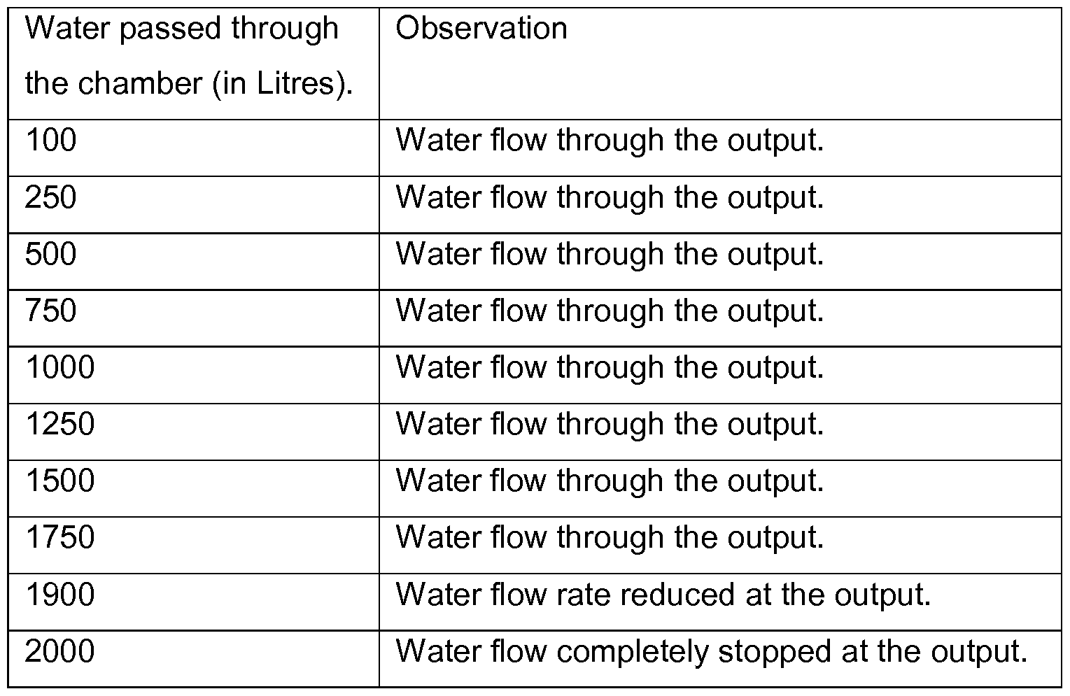
The data on Table 1 shows that the apparatus of the present invention effectively stops the flow of water through the outlet of the chamber at the end of the useful life of the replaceable water treatment unit.
Claims
Claims
1 An apparatus (100) for providing automatic shut off mechanism in a fluid
treatment system, said apparatus comprising:
i. a member (1 ) housable inside a chamber (30) of the fluid treatment system adapted to contain a fluid, where said member is capable of moving in a reciprocating motion in response to the rise and fall of the fluid level of said fluid;
ii. a clockwork mechanism (25) regulated by an escapement mechanism (35); wherein the escapement mechanism (35) is coupled to the member (1 ) for setting the clockwork mechanism (25) in motion as a function of the reciprocating motion of the member (1 ); and,
iii. an arm (17) comprising a plug means or connectable to a plug means (18) wherein the arm (17) is operatively coupled to the clockwork mechanism (25) for intermittently progressing the arm along a path which drives the plug means towards an outlet or inlet of the fluid treatment system thereby shutting off the flow of water.
2 An apparatus as claimed in claim 1 wherein the arm (17) is secured to a main shaft (2) of the clockwork mechanism (25) on one end and the plug means (18) is either fixed or connectable to the other end.
3 An apparatus as claimed in claim 1 wherein when the arm (17) is connectable to the plug means (18), the plug means interacts with a resilient means (19) for maintaining the plug means in open position or closed position for allowing or shutting off the flow of water through the inlet or outlet (31 ) of the chamber (30).
4 An apparatus as claimed in claim 1 comprising an indicator needle (20) with one end secured to the clockwork mechanism (25) and the free end has a needle movable above a dial (21 ).
5 An apparatus as claimed in any one of the preceding claims wherein the
escapement mechanism (35) comprises:
i. an escapement gear (1 1 ) operatively connected to the clockwork mechanism (25); and,
ii. an oscillating arm (13) with one end mounted on the member (1 ) and a free end having at least two pallets (14, 15) engaging with the escapement gear (1 1 ). An apparatus as claimed in claim 1 wherein the clockwork mechanism (25) comprises a ratchet assembly for controlling the rotation of gear assembly in a single direction. An apparatus as claimed in claim 1 wherein the gear of the clockwork mechanism (25) is selected from a spur gear or a bevel gear. An apparatus as claimed in any one of the preceding claims wherein the member (1 ) is mounted between two vertical guides. An apparatus as claimed in any one of the preceding claims wherein the member (1 ) is a float. A fluid treatment system comprising:
i. an inlet for receiving water to be treated and an outlet for allowing the
treated water to flow out; and,
ii. a fluid treatment chamber (30) positioned between the inlet and the outlet wherein the fluid treatment chamber houses a replaceable water treatment unit (40) and the apparatus (100) as claimed in any one of the preceding claims wherein the member (1 ) of the apparatus is positioned within the fluid treatment chamber (30) . A method of actuating an auto-shut off mechanism in a fluid treatment system comprising the apparatus of any one of claims 1 to 9, including the steps of: i. providing energy to be stored in the clockwork mechanism (25);
ii. placing the member (1 ) of the apparatus in a chamber of the water
treatment system housing a replaceable water treatment unit (40);
iii. initiating reciprocating motion of the member (1 ) in response to the rise and fall of the water level in chamber by water entering or exiting the chamber; iv. co-ordinating the reciprocating movement of the member (1 ) to bring the escapement mechanism (35) in operative position which in turn sets the clockwork mechanism in motion as a function of the reciprocating motion of the member (1 );
v. progressing the arm (17) comprising a plug means or connectable to a plug means intermittently along a path which drives the plug means towards an outlet (31 ) or inlet of the chamber; and,
vi. plugging the inlet or outlet (31 ) of the chamber (30). Use of an apparatus as claimed in any one of claims 1 to 9 for providing automatic shut off mechanism in the fluid treatment system. Use of a clockwork mechanism (25) regulated by an escapement mechanism (35); wherein the escapement mechanism (35) is coupled to a member (1 ) for setting the clockwork mechanism (25) in motion as a function of the reciprocating motion of the member (1 ) in an apparatus comprising:
i. a member (1 ) housable inside a chamber (30) of the fluid treatment system adapted to contain a fluid, where said member is capable of moving in a reciprocating motion in response to the rise and fall of the fluid level of said fluid and;
ii. an arm (17) comprising a plug means or connectable to a plug means (18) wherein the arm (17) is operatively coupled to the clockwork mechanism (25) for intermittently progressing the arm along a path which drives the plug means towards an outlet or inlet of the fluid treatment system thereby shutting off the flow of water
for providing auto-shut off mechanism at the end of the useful life of the fluid treatment system.
Applications Claiming Priority (2)
| Application Number | Priority Date | Filing Date | Title |
|---|---|---|---|
| EP16203082.9 | 2016-12-09 | ||
| EP16203082 | 2016-12-09 |
Publications (1)
| Publication Number | Publication Date |
|---|---|
| WO2018104036A1 true WO2018104036A1 (en) | 2018-06-14 |
Family
ID=57542788
Family Applications (1)
| Application Number | Title | Priority Date | Filing Date |
|---|---|---|---|
| PCT/EP2017/079731 Ceased WO2018104036A1 (en) | 2016-12-09 | 2017-11-20 | A metering apparatus for an auto-shut off assembly |
Country Status (1)
| Country | Link |
|---|---|
| WO (1) | WO2018104036A1 (en) |
Citations (7)
| Publication number | Priority date | Publication date | Assignee | Title |
|---|---|---|---|---|
| US1491999A (en) * | 1923-09-12 | 1924-04-29 | Petersson Willy | Liquid meter |
| GB352181A (en) * | 1929-06-28 | 1931-07-09 | Siemens Ag | Improvements in or relating to mechanical integrating gear |
| US2062173A (en) * | 1933-12-23 | 1936-11-24 | Joseph Weidenhoff Inc | Apparatus for measuring the flow of automobile fuel pumps |
| US4681677A (en) * | 1978-02-17 | 1987-07-21 | Olin Corporation | Water processor having automatic shutoff and bypass means |
| WO1998050130A1 (en) * | 1997-05-06 | 1998-11-12 | The Clorox Company | End-of-life indicator for water treatment device |
| EP1138235A1 (en) * | 2000-03-29 | 2001-10-04 | Moulinex S.A. | Electric household appliance with a removable cartridge for treating water |
| WO2015192968A1 (en) | 2014-06-20 | 2015-12-23 | Unilever N.V. | A metering device for an auto-shut off assembly |
-
2017
- 2017-11-20 WO PCT/EP2017/079731 patent/WO2018104036A1/en not_active Ceased
Patent Citations (7)
| Publication number | Priority date | Publication date | Assignee | Title |
|---|---|---|---|---|
| US1491999A (en) * | 1923-09-12 | 1924-04-29 | Petersson Willy | Liquid meter |
| GB352181A (en) * | 1929-06-28 | 1931-07-09 | Siemens Ag | Improvements in or relating to mechanical integrating gear |
| US2062173A (en) * | 1933-12-23 | 1936-11-24 | Joseph Weidenhoff Inc | Apparatus for measuring the flow of automobile fuel pumps |
| US4681677A (en) * | 1978-02-17 | 1987-07-21 | Olin Corporation | Water processor having automatic shutoff and bypass means |
| WO1998050130A1 (en) * | 1997-05-06 | 1998-11-12 | The Clorox Company | End-of-life indicator for water treatment device |
| EP1138235A1 (en) * | 2000-03-29 | 2001-10-04 | Moulinex S.A. | Electric household appliance with a removable cartridge for treating water |
| WO2015192968A1 (en) | 2014-06-20 | 2015-12-23 | Unilever N.V. | A metering device for an auto-shut off assembly |
Similar Documents
| Publication | Publication Date | Title |
|---|---|---|
| EP0792249B1 (en) | End of life mechanism for water treatment cartridge | |
| WO2015192968A1 (en) | A metering device for an auto-shut off assembly | |
| US6423224B1 (en) | Filter cartridge assembly for water treatment device | |
| US4275448A (en) | Electronic means for controlling the regeneration of resins in a resin type ion exchange device | |
| US5022994A (en) | Fluid treatment system | |
| JP5384497B2 (en) | Filtration system with a detachable cartridge, method for determining wear of a detachable cartridge of the filtration system, and kit for performing this method | |
| US9758387B2 (en) | Methods related to proportional regeneration of water treatment systems | |
| RU97110105A (en) | CARTRIDGE WATER TREATMENT INDICATION LIFE MECHANISM | |
| US20100025310A1 (en) | Jug for filtering liquids | |
| US5879559A (en) | Valve controller for water conditioning system | |
| WO2018104036A1 (en) | A metering apparatus for an auto-shut off assembly | |
| PL2119486T5 (en) | Indicator for exchanging a cartridge used in a water filtration device | |
| US4094786A (en) | Treatment control apparatus for water systems | |
| US3249931A (en) | Elapsed time indicator | |
| US6287457B1 (en) | Water treatment device having volumeter driven monitoring discs | |
| DE2300606A1 (en) | WATER METER CONTROLLED PROGRAM FOR THE AUTOMATIC REGENERATION OF WATER SOFTENING SYSTEMS | |
| RU2335325C1 (en) | Water treatment device | |
| CN214916160U (en) | Resin recovery tower cleaning equipment | |
| KR20050022509A (en) | an apparatus to display filter changing time for a water purifier | |
| CN208150999U (en) | A kind of circulating type multilayer sewage-treatment plant | |
| RU2119151C1 (en) | Sedimentation sampler | |
| JP3371334B2 (en) | Water purifier | |
| HK1018769B (en) | Water treatment device with fill-counting cartridge | |
| RU2527854C2 (en) | Vokhmyaninovтs method of service life determination for independent devices for treatment of water fed by gravity (versions) | |
| JP2002214005A (en) | Flow meters and filtration devices |
Legal Events
| Date | Code | Title | Description |
|---|---|---|---|
| 121 | Ep: the epo has been informed by wipo that ep was designated in this application |
Ref document number: 17800549 Country of ref document: EP Kind code of ref document: A1 |
|
| NENP | Non-entry into the national phase |
Ref country code: DE |
|
| 122 | Ep: pct application non-entry in european phase |
Ref document number: 17800549 Country of ref document: EP Kind code of ref document: A1 |