WO2018096685A1 - 情報処理装置、方法およびプログラム - Google Patents
情報処理装置、方法およびプログラム Download PDFInfo
- Publication number
- WO2018096685A1 WO2018096685A1 PCT/JP2016/085227 JP2016085227W WO2018096685A1 WO 2018096685 A1 WO2018096685 A1 WO 2018096685A1 JP 2016085227 W JP2016085227 W JP 2016085227W WO 2018096685 A1 WO2018096685 A1 WO 2018096685A1
- Authority
- WO
- WIPO (PCT)
- Prior art keywords
- detection model
- sample data
- new
- data
- machine learning
- Prior art date
- Legal status (The legal status is an assumption and is not a legal conclusion. Google has not performed a legal analysis and makes no representation as to the accuracy of the status listed.)
- Ceased
Links
Images




Classifications
-
- H—ELECTRICITY
- H04—ELECTRIC COMMUNICATION TECHNIQUE
- H04L—TRANSMISSION OF DIGITAL INFORMATION, e.g. TELEGRAPHIC COMMUNICATION
- H04L12/00—Data switching networks
- H04L12/66—Arrangements for connecting between networks having differing types of switching systems, e.g. gateways
Definitions
- This disclosure relates to a technique for detecting a predetermined type of communication.
- traffic data to be transmitted over a network is input, learning data created by a learning data creation device, variable selection means for selecting a variable from the traffic data, and the selected variable such as a neural network or a decision tree
- variable selection means for selecting a variable from the traffic data, and the selected variable such as a neural network or a decision tree
- a processing unit that performs analysis using an analysis algorithm and generates a pattern
- an evaluation unit that evaluates the analysis result using the generated pattern
- An intrusion detection system has been proposed in which a pattern effective for intrusion detection is generated and abnormal traffic data is detected by performing at least once (see Patent Document 1).
- JP 2004-312083 A Japanese Unexamined Patent Publication No. 2016-91549 US Patent Application Publication No. 2015/0128263 US Patent Application Publication No. 2004/0059947
- the work accompanying the update of the detection function requires work that requires human intervention and time, such as detection logic update and evaluation of the detection logic after the update.
- detection logic update in order to cope with the detection of a new type of communication, a person designs a new detection logic after finding a law from actual communication data, and performs coding based on it. Work to be performed is performed.
- evaluation of the detection logic after the update a person evaluates whether or not the detection logic after the update can detect a new type of communication. For this reason, it is heavy for a person to continuously update the detection function.
- an object of the present disclosure is to efficiently generate a high-performance detection model using limited specimen data.
- An example of the present disclosure includes: a sample data input receiving unit that receives input of new sample data related to a predetermined type of communication; and the new sample data is converted into machine learning sample data using a plurality of different division patterns.
- Detection model generation for generating a detection model for detecting the predetermined type of communication for each division pattern by sample data dividing means for dividing into test sample data and machine learning using the machine learning sample data
- a detection model evaluation unit that evaluates the performance of the detection model using the test specimen data.
- the detection model generation unit newly detects a model having the highest performance among the generated detection models. This is an information processing apparatus as a model.
- the present disclosure can be grasped as an information processing apparatus, a system, a method executed by a computer, or a program executed by a computer.
- the present disclosure can also be understood as a program recorded on a recording medium readable by a computer, other devices, machines, or the like.
- a computer-readable recording medium refers to a recording medium that stores information such as data and programs by electrical, magnetic, optical, mechanical, or chemical action and can be read from a computer or the like.
- the information processing apparatus, method, and program according to the present disclosure are implemented in a system for monitoring a network and detecting malicious communication mainly related to a cyber attack as a predetermined type of communication. Will be described.
- the information processing apparatus, method, and program according to the present disclosure can be widely used for techniques for detecting a predetermined type of communication, and the application target of the present disclosure is the example shown in the present embodiment. It is not limited.
- the detection target may be a predetermined type of communication, and normal communication may be the detection target.
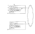
- FIG. 1 is a schematic diagram illustrating a configuration of a system 1 according to the present embodiment.
- a system 1 according to the present embodiment includes a detection model generation device 10 that automatically generates a detection model used for detecting a predetermined type of communication, and a plurality of networks that detect a predetermined type of communication using the detection model.
- Monitoring devices 20A and 20B In the case where it is not specified which network monitoring device, it is simply described as “network monitoring device 20”. Although only two network monitoring devices 20 are shown in FIG. 1, three or more network monitoring devices 20 may be used.
- each of the plurality of network monitoring devices 20A and 20B does not specify network segments 2A and 2B (which network segment is connected) to which a plurality of information processing terminals 90 (hereinafter referred to as “nodes 90”) are connected.
- the network segment 2 is simply described as “network segment 2”.
- the node 90 and the network monitoring device 20 in the network segment 2 can communicate with various servers (including the detection model generation device 10) connected at remote locations via the Internet or a wide area network.
- the network monitoring device 20 is a detection device such as a sensor equipped with a targeted cyber attack detection technology (for example, “Malicous Intrusion Process Scan” technology of PFU Corporation), and is a switch or router of the network segment 2 And other switches or routers in the higher level, it acquires packets and frames that pass through and detects a predetermined type of communication.
- the network monitoring device 20 operates in an inline mode in which packets that do not need to be blocked among the acquired packets are transferred.
- the network monitoring device 20 may acquire a packet, a frame, or the like transmitted / received by the node 90 by being connected to a monitoring port (mirror port) of a switch or a router (illustration is omitted). In this case, the network monitoring device 20 operates in a passive mode in which the acquired packet is not transferred. In addition, for example, the network monitoring device 20 is not connected to the monitoring port (mirror port) but is simply connected to the network segment 2, and the frame flowing through the network segment 2 is not addressed to its own MAC address.
- the network monitoring device 20 By acquiring everything including the packet, it is possible to acquire packets, frames, and the like transmitted and received by the node 90. Also in this case, the network monitoring device 20 operates in the passive mode.
- the network monitoring device 20 may be included in a router or a switch.
- FIG. 2 is a diagram illustrating a hardware configuration of the detection model generation device 10 and the network monitoring device 20 according to the present embodiment.
- the detection model generation device 10 includes a CPU (Central Processing Unit) 11, a ROM (Read Only Memory) 12, a RAM (Random Access Memory) 13, an EEPROM (Electrically Readable Memory Readable Memory, and a Programmable HDD).
- the computer includes a storage unit 14, a communication unit such as a NIC (Network Interface Card) 15, and the like.
- NIC Network Interface Card
- the network monitoring device 20 is a computer including a CPU, ROM, RAM, storage, communication unit, and the like.
- the network monitoring device 20 acquires communication data transmitted / received by a terminal connected to the network, and inspects the data according to an inspection item determined according to the protocol. For example, when it is determined that the protocol related to the flow is HTTP, the network monitoring device 20 inspects data according to the inspection items defined for HTTP.
- the network monitoring device 20 uses the detection model generated and distributed by the detection model generation device 10 at the time of this inspection.
- the network monitoring device 20 stores data (a trail) related to the event or notifies the user of the detection of the event.
- the “terminal” to be monitored and detected by the network monitoring device 20 includes, in addition to the node 90 connected to the network segment 2, other devices that communicate with the node 90 via a router ( Nodes belonging to other networks, external servers, etc.).
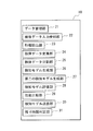
- FIG. 3 is a diagram illustrating an outline of a functional configuration of the detection model generation device 10 according to the present embodiment.
- the detection model generation apparatus 10 reads out a program recorded in the storage 14 to the RAM 13 and executes it by the CPU 11, whereby the data management unit 21, the sample data input reception unit 22, the feature extraction unit 23, the sample data Information including a conversion unit 24, a specimen data division unit 25, a detection model generation unit 26, a second detection model generation unit 27, a detection model evaluation unit 28, a performance comparison unit 29, a detection model transmission unit 30, and a remaining time determination unit 31 Functions as a processing device.
- each function included in the detection model generation device 10 is executed by the CPU 11 that is a general-purpose processor. However, some or all of these functions may be executed by one or more dedicated processors. Good. Some or all of these functions may be executed by a device installed in a remote place or a plurality of devices installed in a distributed manner using cloud technology or the like.
- the data management unit 21 saves new specimen data and new features in association with a predetermined environment, so that a current type for detecting a predetermined type of communication in the predetermined environment is stored.
- Existing features and existing specimen data used to generate a detection model are stored.
- existing features are stored in the feature data management database
- existing sample data is stored in the sample data management database.
- feature data with an environment identifier “common” indicating that it is used in any environment is stored in advance, and the specimen data management database is used in any environment. The sample data to which the environmental identifier “common” shown is stored in advance.
- the specimen data input receiving unit 22 receives input of new specimen data related to a predetermined type of communication.
- the feature extraction unit 23 extracts new features different from existing features from the new specimen data.
- the specimen data conversion unit 24 converts the existing specimen data and the new specimen data into a predetermined data format for machine learning using the existing feature and the new feature. At this time, the sample data conversion unit 24 converts the sample data so as to have a data format suitable for the machine learning method used by the detection model generation unit 26. For example, when the detection model generation unit 26 generates a detection model by random forest method machine learning, the sample data conversion unit 24 converts the sample data by the Bag-of-Words (BoW) method, and the detection model generation unit 26 When the detection model is generated by neural network type machine learning (for example, a convolutional neural network or a recurrent neural network), the specimen data conversion unit 24 converts the data in the specimen data into unique numerical values corresponding to each feature. Convert the specimen data by the method.
- neural network type machine learning for example, a convolutional neural network or a recurrent neural network
- the sample data conversion unit 24 obtains the number of appearances of each existing and new feature for each HTTP request header and has them as dimensions. Conversion into vector data (BoW vector generation). More specifically, when the feature is “Host:”, “abc”, “efg”, the pre-conversion data “Host: abc” is converted into the BoW vector [1, 1, 0], and the pre-conversion data “Host: efg "is converted into a BoW vector [1, 0, 1].
- the sample data dividing unit 25 divides new sample data into machine learning sample data and test sample data using a plurality of different division patterns.
- a performance index (hereinafter referred to as “Accuracy” in the examples) calculated for each detection model is used to determine whether or not to continue the specimen data division process.
- the specimen data dividing unit 25 performs the “detection model generated using the first division pattern” according to the determination condition (
- the specimen data dividing unit 25 compares with “the performance of the detection model generated using the first division pattern”.
- the performance of the detection model generated by using the second division pattern obtained by increasing the machine learning sample data from the first division pattern is more than a predetermined value, it is better than the second division pattern.
- a third division pattern in which the machine learning sample data is increased is further generated.
- the detection model generation unit 26 generates a detection model for detecting a predetermined type of communication for each division pattern by machine learning using machine learning sample data and existing sample data, and the generated detection model Among them, the model with the highest performance is set as a new detection model.
- machine learning sample data converted into a predetermined data format is used.
- the second detection model generation unit 27 generates a second new detection model using a machine learning algorithm different from the detection model generation unit 26 or a different machine learning parameter.
- the detection model generation device 10 includes a plurality of second detection model generation units 27.2 to 27. m may be provided.
- a plurality of second detection model generation units 27.2 to 27. m generates different second new detection models by using machine learning algorithms or machine learning parameters that are different from each other.
- the detection model evaluation unit 28 evaluates the performance of the detection model using the test specimen data.
- the performance comparison unit 29 compares the current detection model for detecting a predetermined type of communication with the performance of one or more new detection models, and is approximately equivalent to the current detection model (for example, within an error range) or A new detection model having performance larger than that of the current detection model is determined as an update detection model for replacing the current detection model.
- the detection model transmission unit 30 transmits the detection model for update to the network monitoring device 20 and updates the detection model used in the network monitoring device 20.
- the remaining time determination unit 31 divides new sample data using different division patterns by the sample data dividing unit 25, the remaining time up to a preset upper limit time until the detection model for update is obtained (Tr ) And the estimated processing time (Tr′ ⁇ Tr), and determines whether the estimated processing time exceeds the remaining time.
- the sample data dividing unit 25 ends the processing.
- the division processing itself is regarded as a failure and the process is terminated.
- the sample data dividing unit 25 and the detection model generating unit 26 have the estimated processing time remaining.
- a new detection model may be determined using the detection model generated by the processing so far.
- FIG. 4 is a flowchart showing an outline of the flow of the detection model generation process for update according to this embodiment.
- the detection model generation process for update according to the present embodiment is executed when the specimen data of the cyber attack in a predetermined environment is input to the detection model generation apparatus 10.
- step S001 input of cyber attack specimen data is accepted.
- the sample data input receiving unit 22 is a predetermined environment (for example, a local network in which the network monitoring device 20A is installed) in which a current detection model for detecting a predetermined type of communication (here, a cyber attack) is used. Accepts sample data for cyber attacks.
- the sample data input receiving unit 22 records the input cyber attack sample data in the RAM 13 or the storage 14 as new sample data.
- a local network in which the network monitoring device 20A is installed is referred to as “environment A”, and generation of an update detection model used in the network monitoring device 20A will be described.
- the sample data accepted here is data that has already been classified with respect to the presence or absence of a cyber attack, and the correct answer label (information indicating the presence or absence of a cyber attack) is attached to the sample data. Thereafter, the process proceeds to step S002.
- step S002 feature extraction processing is executed.
- the feature extraction unit 23 extracts a new feature from the input new specimen data. Details of the feature extraction processing will be described later with reference to FIG. Thereafter, the process proceeds to step S003.
- step S003 and step S004 the specimen data division process is executed, and the success or failure of the division is determined.
- the sample data dividing unit 25 divides new sample data for machine learning and for testing, and the detection model generating unit 26 generates one new detection model in the process of division (S003). That is, in the present embodiment, at least one new detection model is generated when it is determined how to divide the specimen data into machine learning and test. Details of the sample data division processing will be described later with reference to FIGS.
- step S004 it is determined whether or not the new sample data input in step S001 has been successfully divided. When the division of new sample data fails, the processing shown in this flowchart ends. On the other hand, when the division of the new sample data is successful, the process proceeds from step S005 and steps S006.2 to S006. Proceed to m.
- step S005 sample data conversion using existing features is performed.
- the sample data conversion unit 24 converts all sample data (existing sample data + new sample data) into a format suitable for the input data of the machine learning algorithm using the existing features. Thereafter, the process proceeds to step S007.
- the specimen data is converted using the existing feature and the new feature, and the second new detection model is generated.
- Each process of m is processed in parallel by a single server or a plurality of servers. Details of the second new detection model generation process processed in each server will be described later with reference to FIG. Thereafter, the process proceeds to step S007.
- step S007 and step S008 a performance comparison process is executed, and it is determined whether or not there is a new detection model (update detection model) to be replaced with the current detection model.
- the performance comparison unit 29 compares one or a plurality of new detection models (including the second new detection model) generated so far with the current detection model, and replaces the current detection model based on the comparison result.
- An update detection model is determined (step S007). Details of the performance comparison processing will be described later with reference to FIGS. 10 and 11.
- the process shown in this flowchart ends.
- the process proceeds to step S009.
- step S009 data management processing is executed.
- the data management unit 21 associates the new sample data and the correct answer label (information indicating the presence / absence of a cyber attack) with each other and stores them in the sample data management database as data of the environment identifier “environment A”. Further, the data management unit 21 stores the new feature in the feature data management database as data of the environment identifier “environment A”. Thereafter, the process proceeds to step S010.
- step S010 the detection model for update is transmitted to the network monitoring device 20.
- the detection model transmission unit 30 transmits a new detection model (update detection model) to be replaced with the current detection model to the network monitoring device 20.
- the network monitoring apparatus 20 that has received the update detection model sets the received update detection model as a new current detection model, and subsequently detects a cyber attack using the new current detection model. Thereafter, the processing shown in this flowchart ends.
- FIG. 5 is a flowchart showing an outline of the flow of feature extraction processing according to the present embodiment. This flowchart is for explaining in detail the process in step S002 of the detection model generation process for update (see FIG. 4).
- step S101 existing sample data is extracted.
- the feature extraction unit 23 extracts the sample data corresponding to the environment identifier “common”, the sample data corresponding to “environment A”, and the correct label (information indicating the presence / absence of a cyber attack) from the sample data management database. Thereafter, the process proceeds to step S102.
- step S102 existing features are extracted.
- the feature extraction unit 23 extracts the sample data corresponding to the environment identifier “common” and the feature data corresponding to “environment A” from the feature data management database. Thereafter, the process proceeds to step S103.
- step S103 a new specimen data decomposition process is performed.
- the feature extraction unit 23 decomposes the content of the new sample data for each word by a method such as using a regular expression as a decomposition rule.
- a regular expression for example, when the sample data is an HTTP request header group, the feature extraction unit 23 can decompose the contents of the request header group for each word using the following regular expression as a decomposition rule. [a-zA-Z0-9:] [a-zA-Z0-9 _ ⁇ -:.] + ⁇ b
- the process proceeds to step S104.
- step S104 a new feature is extracted.
- the feature extraction unit 23 extracts new features (features that do not exist in the existing features) from the new sample data by matching the new sample data with the existing features. Thereafter, the processing shown in this flowchart ends.
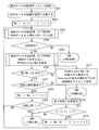
- FIG. 6 is a flowchart showing an outline of the flow of the specimen data division process (main process) according to this embodiment. This flowchart is for explaining in detail the process in step S003 of the detection model generation process for update (see FIG. 4).
- step S201 sample data conversion using existing features and new features is performed.
- the sample data conversion unit 24 converts all sample data (existing sample data + new sample data) into a format suitable for the input data of the machine learning algorithm using the existing feature and the new feature. Thereafter, the process proceeds to step S202.
- step S202 variables are initialized.
- the sample data dividing unit 25 sets initial values for each variable used for processing. Specifically, the sample data dividing unit 25 sets 0 to the average Accuracy (Ma ′) calculated at the time of the number of divisions one loop before in the loop processing from step S203 to step S212 described later, and the number of divisions one loop before The remaining time (Tr ′) estimated at the time of 0 is set to 0, and the division number (n) is set to 2. Thereafter, the process proceeds to step S203.
- Ma ′ the average Accuracy
- step S203 the sample data is divided.
- the sample data dividing unit 25 divides new sample data into n pieces (sample data dividing process (sub-process A)). Details of the sample data division process (sub-process A) will be described later with reference to FIG. Thereafter, the process proceeds to step S204.
- step S204 and step S205 when the division is successful, a detection model is generated and an average accuracy (Ma) is calculated. If the sample data division process (sub-process A) in step S203 fails in the division, the processing shown in this flowchart ends (division failure). On the other hand, when the division is successful, the detection model generation unit 26 generates n detection models, and the sample data division unit 25 calculates an average accuracy (Ma) (sample data division process (sub-process B)). . This is because, when new sample data is divided into n, there are n methods for selecting a divided group of sample data for machine learning for accuracy calculation, and n detection models can be generated.
- Ma average accuracy
- the detection model evaluation unit 28 calculates Accuracy for each of the n detection models, and the sample data division unit 25 sets the average value as the average Accuracy (Ma). Details of the sample data division process (sub-process B) will be described later with reference to FIG. Thereafter, the process proceeds to step S206.
- step S206 it is determined whether or not the average accuracy has changed more than a predetermined value by increasing the number of divisions n.
- the sample data dividing unit 25 is more than a predetermined value between the average accuracy (Ma ′) calculated at the time of the number of divisions before one loop and the average accuracy (Ma) calculated at the time of the current number of divisions (n). It is determined whether there is a difference (for example, a difference larger than a predetermined value).
- the determination is performed using the following mathematical formula.
- step S207 If there is a difference greater than or equal to the predetermined value, it is determined that there is a high possibility of improving the average accuracy by increasing the number of divisions (in other words, the amount of machine learning sample data), and the process proceeds to step S207. On the other hand, when there is no difference greater than or equal to a predetermined value (equivalent), there is little possibility of improving the average accuracy by increasing the number of divisions (in other words, the amount of sample data for machine learning), and the division before one loop is low. It is determined that the sample data division by number is appropriate, and the process proceeds to step 213.
- the division process from step S203 to step S206 is repeatedly executed while increasing the division number n (increasing the amount of machine learning sample data) until the average accuracy no longer changes more than a predetermined value.
- n increments the amount of machine learning sample data
- the sample data dividing unit 25 specifies the ratio of the learning sample data (amount of the learning sample data) when the increase in the performance of the detection model starts to become gentle (or constant) by using the above determination condition. Then, this is set as a minimum learning sample data ratio (amount of learning sample data) necessary for generating a detection model, and the remaining sample data is used as test sample data.
- the method of dividing the sample data equally into groups of powers of 2 (2, 4, 8, 16,...) Is used for dividing the sample data.
- Other methods may be used as the method.
- a method of increasing the amount of sample data used as sample data for machine learning in the sample data by a certain amount or a certain ratio may be employed.
- step S207 when the division upper limit number (Nmax) is defined, it is determined whether the division number (n) has reached the upper limit.
- the sample data dividing unit 25 determines whether or not the division upper limit number (Nmax) is defined (step S207).
- the sample data division unit 25 sets a value obtained by doubling the current division number (n) as a new division number (n), and in this process
- the calculated average accuracy (Ma) is set as the average accuracy (Ma ′) calculated when the number of divisions is one loop before (step S208).
- step S210 when the division upper limit number (Nmax) is not defined, it is determined whether to continue the process based on the remaining time that can be used for the process.
- the remaining time determination unit 31 estimates the remaining time (Tr) that can be used in the sample data division process (step S210).
- Tmax upper limit time [seconds] until the detection model for update is determined (from feature extraction processing to performance comparison processing)
- Tb Time required immediately before “sample data division processing” [seconds]
- Ts Time required for executing “specimen data division processing” i times [seconds]
- Ta Estimated time required for detection model generation processing and detection performance comparison processing [seconds]
- t Maximum value [second] of “one detection model generation time + Accuracy calculation time” in the i-th sample data division processing
- m Total number of current detection models and second new detection models generated in “processing of m from second new detection model generation process 2” M: server used when generating second new detection models in parallel
- the required upper limit time (Tmax) may be
- the remaining time determination unit 31 When the remaining time (Tr) that can be used in the sample data division processing is estimated, the remaining time determination unit 31 newly estimates the remaining time (Tr ′) estimated from the remaining time (Tr ′) estimated when the number of divisions is one loop before.
- the estimated processing time may be calculated by other methods, and other conditional expressions may be adopted as the determination conditions.
- the sample data division unit 25 sets a value obtained by doubling the current division number (n) as the new division number (n).
- the value of the average accuracy (Ma) calculated in the current process is set as the average accuracy (Ma ′) calculated in the case of the number of divisions before one loop, and the remaining time estimated in the current process
- the value of (Tr) is set as the remaining time (Tr ′) estimated when the number of divisions is one loop before (step S212). Thereafter, the process returns to step S203, and the sample data is divided using the new division number (n).
- a new detection model is determined.
- the detection model generation unit 26 detects the maximum accuracy among the detection model groups whose average accuracy is Ma ′.
- a model is adopted as the new detection model 1, and a machine learning detection data and test detection data division pattern corresponding to the new detection model is adopted.
- the detection model generation unit 26 is less likely to improve the average accuracy by increasing the number of divisions (in other words, the amount of sample data for machine learning), and the sample data division by the number of divisions before one loop is low.
- a detection model generated using the amount of sample data for machine learning by sample data division by the number of divisions before one loop is adopted as the new detection model 1. Thereafter, the processing shown in this flowchart ends (division success).
- the process ends as “division failure”.
- the specimen data dividing unit 25 and the detection model generating unit 26 may determine a new detection model using the detection model generated by the processing so far. This is because there is a possibility that a new detection model equivalent to or better than the current detection model can be generated even in the range of results executed so far. In this case, the process proceeds to step S213, and the detection model generation unit 26 adopts the detection model having the maximum accuracy in the processes so far as the new detection model, and adopts the corresponding division pattern.
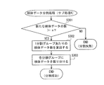
- FIG. 7 is a flowchart showing an outline of the flow of the sample data division process (sub-process A) according to the present embodiment. This flowchart is for explaining in detail the processing in step S203 of the sample data division processing (main processing) (see FIG. 6).
- step S301 the number of new specimen data is determined. If the number of new sample data is smaller than the number of divisions (n), the division cannot be executed, and the processing shown in this flowchart ends (division failure). On the other hand, if the number of new sample data is equal to or greater than the division number (n), the process proceeds to step S302.
- step S302 the number of specimen data per divided group is calculated.
- the sample data dividing unit 25 calculates the number of “new sample data” per division group by dividing the number of “new sample data” by the division number (n). Thereafter, the process proceeds to step S303.
- step S303 the sample data is distributed to each divided group.
- the sample data dividing unit 25 generates n divided groups by randomly selecting sample data for each divided group by the number of “new sample data” per divided group calculated in step S302. To do. At this time, it is assumed that the sample data is assigned to each divided group so as not to overlap. Thereafter, the processing shown in this flowchart ends (division success).
- FIG. 8 is a flowchart showing an outline of the flow of the specimen data division process (sub-process B) according to the present embodiment. This flowchart is for explaining in detail the processing in step S205 of the sample data division processing (main processing) (see FIG. 6).
- step S401 variables are initialized.
- the sample data dividing unit 25 sets initial values for each variable used for processing. Specifically, the sample data dividing unit 25 sets 1 to the index (i). Thereafter, the process proceeds to step S402.
- step S402 the divided groups are allocated for testing and machine learning.
- the sample data dividing unit 25 selects the i-th divided group for test and the rest for machine learning out of the “new sample data” divided into n pieces. Thereafter, the process proceeds to step S403.
- a detection model is generated.
- the detection model generation unit 26 generates a detection model by using a machine learning algorithm (for example, a random forest) using the converted all machine specimen data for machine learning and the corresponding correct answer label as input data. Thereafter, the process proceeds to step S404.
- a machine learning algorithm for example, a random forest
- step S404 Accuracy is calculated.
- the detection model evaluation unit 28 inputs the “new sample data” for the converted test to the detection model, and obtains Accuracy.
- Accuracy is calculated using the following mathematical formula.
- Accuracy (TP + TN) / (TP + FN + FP + TN)
- TP Number of detection data detected using test target detection model among test sample data for cyber attack “Yes”
- FN Detection model for test target among test sample data for cyber attack “Yes”
- Number of detected data not detected using FP Number of detected data falsely detected as a cyber attack using the test target detection model among test sample data for cyber attack “No”
- TN Cyber The number of detection data that has not been detected using the test target detection model among the test sample data for the attack “nothing”.
- Accuracy may be calculated by other methods. Thereafter, the process proceeds to step S405.
- step S405 and step S406 the index (i) is updated, and it is determined whether or not to continue the process.
- the sample data dividing unit 25 increments the index (i) by 1 (step S405).
- the updated index (i) is compared with the division number (n), and if the comparison result index (i) is equal to or less than the division number (n) (NO in step S406), the process returns to step S402.
- the processes from step S402 to step S405 are re-executed. That is, the processing from step S402 to step S405 is repeatedly executed for the number of divisions (n), and n detection models are generated.
- the comparison result index (i) is larger than the number of divisions (n) (YES in step S406), the process proceeds to step S407.
- step S407 an average accuracy is calculated.
- the sample data dividing unit 25 obtains an average accuracy from the accuracy of the generated n detection models. Thereafter, the processing shown in this flowchart ends.
- FIG. 9 is a flowchart showing an outline of the flow of the second new detection model generation process according to the present embodiment. This flowchart is for explaining in detail the process in step S006 of the detection model generation process for update (see FIG. 4).
- step S501 sample data conversion using existing features and new features is performed.
- the sample data conversion unit 24 converts all sample data (existing sample data + new sample data) into a format suitable for the input data of the machine learning algorithm using the existing feature and the new feature. Thereafter, the process proceeds to step S502.
- a second new detection model is generated.
- the second detection model generation unit 27 generates a detection model using a machine learning algorithm using the converted data and the corresponding correct answer label (information indicating the presence or absence of a cyber attack) as input data. At least one of the machine learning algorithm and the machine learning parameter used at this time is different from that used in the detection model generation in step S403. Thereafter, the processing shown in this flowchart ends.
- FIG. 10 is a flowchart showing an outline of the flow of the performance comparison process (main process) according to the present embodiment. This flowchart is for explaining in detail the process of step S007 of the detection model generation process for update (see FIG. 4). Note that the processing in step S601 and step S602 according to the present embodiment is performed in parallel by a single server or a plurality of servers.
- step S601 performance (detection accuracy) comparison with the current detection model is performed using the new sample data as test sample data.
- the performance comparison unit 29 checks whether there is a new detection model (including the second new detection model) that is equal to or better than the performance of the current detection model, using the converted new specimen data (for testing). Details of the performance comparison process (sub-process) will be described later with reference to FIG.
- the new detection model extracted here is referred to as “candidate A”. Thereafter, the process proceeds to step S603.
- step S602 among the existing test sample data stored in the sample data management database, the sample data with the environment identifier “common” and the sample data with “environment A” are used to obtain the current detection model. A performance comparison is made.
- the performance comparison unit 29 confirms whether there is a new detection model (including the second new detection model) equal to or higher than the performance of the current detection model, using the converted existing specimen data (for testing). Details of the performance comparison process (sub-process) will be described later with reference to FIG.
- the new detection model extracted here is referred to as “candidate B”. Thereafter, the process proceeds to step S603.
- step S603 it is determined whether “candidate A” and “candidate B” have been determined.
- the processing illustrated in this flowchart ends. (No replacement).
- the process proceeds to step S604.
- step S606 an update detection model is determined.
- the performance comparison unit 29 adopts the new detection model as an update detection model (step S605).
- the performance comparison unit 29 adopts the new detection model of “candidate A” as an update detection model (step S606). This is to preferentially adopt a detection model that can detect an attack or the like related to new sample data. Thereafter, the processing shown in the flowchart ends (replacement target determination).
- FIG. 11 is a flowchart showing an outline of the flow of performance comparison processing (sub-processing) according to the present embodiment. This flowchart is for explaining in detail the process of step S601 or step S602 of the performance comparison process (main process) (see FIG. 10).
- step S701 an evaluation value for performance comparison is calculated.
- the performance comparison unit 29 uses the converted test sample data to detect the cyber attack detection rate (hereinafter referred to as “Recall”) and the correct response rate (hereinafter referred to as “Recall”) of the current detection model and the new detection model. Called “Precision”).
- Recall and Precision are calculated using the following mathematical formulas.
- step S702 a performance comparison using the calculated evaluation value is performed.
- step S703 replacement candidates are determined from new detection models that satisfy the conditions.
- the candidate determined here is “candidate A” when the process of this flowchart is called from step S601, and is “candidate B” when the process of this flowchart is called from step S602.
- the performance comparison unit 29 adopts the new detection model having the largest Precision as the detection model having the highest performance, and replaces the candidate (“candidate A Or “candidate B”) (step S704).
- the performance comparison unit 29 adopts the corresponding new detection model as the detection model having the highest performance, and replaces the candidate (“candidate A” or “candidate B”). ]). Thereafter, the processing shown in this flowchart ends (replacement candidate determination).
- the performance comparison unit 29 detects the detection rate of a predetermined type of communication (the rate at which an actual attack is detected as an attack) and the correct answer rate of the detection result that the predetermined type of communication is an attack (attack)
- the performance comparison is performed based on both of the ratio of the actual attacks detected as This means that if normal communication is detected as a cyber attack, normal communication is restricted or blocked, and operation continuity cannot be maintained. At the same time, it is necessary to avoid misidentifying normal communication as a cyber attack.
- ⁇ Effect> According to the information processing apparatus, method, and program according to the present embodiment, it is possible to save the detection logic update of the detection system, and it is easy to continuously update. That is, it is possible to efficiently generate a high-performance detection model using limited sample data, and it is possible to reduce the trouble of updating the detection logic. In addition, since it is possible to generate a detection model that balances “maintenance of operation continuity” and “improvement of safety”, it is possible to cope with improvement of safety against cyber attacks in addition to maintenance of service level.
Landscapes
- Engineering & Computer Science (AREA)
- Computer Networks & Wireless Communication (AREA)
- Signal Processing (AREA)
- Data Exchanges In Wide-Area Networks (AREA)
Abstract
限られた検体データを用いて、性能の高い検知モデルを効率的に生成することを課題とする。情報処理装置に、所定の種類の通信に係る新たな検体データの入力を受け付ける検体データ入力受付部と、新たな検体データを、互いに異なる複数の分割パターンを用いて機械学習用検体データとテスト用検体データに分割する検体データ分割部と、機械学習用検体データを用いた機械学習によって、分割パターン毎に、所定の種類の通信を検知するための検知モデルを生成する検知モデル生成部と、テスト用検体データを用いて検知モデルの性能を評価する検知モデル評価部と、を備え、検知モデル生成部は、生成された検知モデルのうち最も性能の高いモデルを新検知モデルとする。
Description
本開示は、所定の種類の通信を検知するための技術に関する。
従来、ネットワーク上を伝送するトラヒックデータを入力し、学習データ作成装置により作成された学習データと前記トラヒックデータから変数を選択する変数選択手段と、該選択された変数をニューラルネットや決定木等の解析アルゴリズムを用いて解析を行い、パターンを生成する処理手段と、該生成されたパターンを用いて前記解析結果を評価する評価手段とを有し、前記変数選択手段および処理手段、評価手段における処理を1回以上行うことにより、侵入の検知に有効なパターンを生成して異常なトラヒックデータを検知する侵入検知システムが提案されている(特許文献1を参照)。
また、その他にも、サイバー攻撃を検知するために、機械学習を用いるシステムが種々提案されている(特許文献2から4を参照)。
従来、サイバー攻撃(マルウェアを含む)等の所定の種類の通信を検知するために、検知対象とパターンファイルをマッチングさせるパターンマッチング検知や、プログラムやソフトウェアの挙動に基づいて判定する振る舞い検知などが実施されている。このような検知技術を実施するにあたっては、日々進化を続け種類が増え続けている通信の種類に対応するため、検知機能の継続的な更新が重要である。
しかし、検知機能の更新に伴う作業には、検知ロジックの更新、および更新後の検知ロジックの評価等の、人が介在すると共に時間がかかる作業が必要である。例えば、検知ロジックの更新では、新たな種類の通信の検知に対応するために、人が、実際の通信のデータから法則を見出した上で新たな検知ロジックを設計し、それを基にコーディングを実施する作業が行われる。また、更新後の検知ロジックの評価では、更新後の検知ロジックが、新たな種類の通信を検知できるかどうかを、人が評価する作業が行われる。このため、検知機能の更新を継続的に実施するには、人の負担が大きい。
ここで、検知ロジックを機械学習によって自動生成された検知モデルに置き換えることで、上記の作業を自動化することが考えられる。しかし、この場合、量が限られた検体データを、検知モデルの生成に使用する機械学習用検体データと、検知モデルの性能(検知精度)の比較に使用するテスト用検体データとに分ける必要がある。そして、新しく入手した検体データを機械学習用とテスト用に分ける場合、どのように分けるのが、性能の高い検知モデルを生成するために最適であるかについては、検体データの種類や数などを含む環境によって異なる。
本開示は、上記した問題に鑑み、限られた検体データを用いて、性能の高い検知モデルを効率的に生成することを課題とする。
本開示の一例は、所定の種類の通信に係る新たな検体データの入力を受け付ける検体データ入力受付手段と、前記新たな検体データを、互いに異なる複数の分割パターンを用いて機械学習用検体データとテスト用検体データに分割する検体データ分割手段と、前記機械学習用検体データを用いた機械学習によって、分割パターン毎に、前記所定の種類の通信を検知するための検知モデルを生成する検知モデル生成手段と、前記テスト用検体データを用いて前記検知モデルの性能を評価する検知モデル評価手段と、を備え、前記検知モデル生成手段は、生成された検知モデルのうち最も性能の高いモデルを新検知モデルとする、情報処理装置である。
本開示は、情報処理装置、システム、コンピューターによって実行される方法またはコンピューターに実行させるプログラムとして把握することが可能である。また、本開示は、そのようなプログラムをコンピューターその他の装置、機械等が読み取り可能な記録媒体に記録したものとしても把握できる。ここで、コンピューター等が読み取り可能な記録媒体とは、データやプログラム等の情報を電気的、磁気的、光学的、機械的または化学的作用によって蓄積し、コンピューター等から読み取ることができる記録媒体をいう。
本開示によれば、限られた検体データを用いて、性能の高い検知モデルを効率的に生成することが可能となる。
以下、本開示に係る情報処理装置、方法およびプログラムの実施の形態を、図面に基づいて説明する。但し、以下に説明する実施の形態は、実施形態を例示するものであって、本開示に係る情報処理装置、方法およびプログラムを以下に説明する具体的構成に限定するものではない。実施にあたっては、実施の態様に応じた具体的構成が適宜採用され、また、種々の改良や変形が行われてよい。
本実施形態では、本開示に係る情報処理装置、方法およびプログラムを、ネットワークを監視し、主にサイバー攻撃に係る悪意の通信を所定の種類の通信として検知するためのシステムにおいて実施した場合の実施の形態について説明する。但し、本開示に係る情報処理装置、方法およびプログラムは、所定の種類の通信を検知するための技術について広く用いることが可能であり、本開示の適用対象は、本実施形態において示した例に限定されない。例えば、検知の対象は、所定の種類の通信であればよく、正常な通信が検知の対象とされてもよい。
<システムの構成>
図1は、本実施形態に係るシステム1の構成を示す概略図である。本実施形態に係るシステム1は、所定の種類の通信の検知に用いられる検知モデルを自動的に生成する検知モデル生成装置10と、検知モデルを用いて所定の種類の通信を検知する複数のネットワーク監視装置20Aおよび20Bと、を備える。なお、何れのネットワーク監視装置であるかを特定しない場合には単に「ネットワーク監視装置20」と記載する。図1にはネットワーク監視装置20を2つのみ図示しているが、3以上であってもよい。また、複数のネットワーク監視装置20Aおよび20Bの夫々は、複数の情報処理端末90(以下、「ノード90」と称する)が接続されるネットワークセグメント2Aおよび2B(何れのネットワークセグメントであるかを特定しない場合には単に「ネットワークセグメント2」と記載する。)に配置され、各ネットワークセグメント2においてノード90に係る通信を監視する。
図1は、本実施形態に係るシステム1の構成を示す概略図である。本実施形態に係るシステム1は、所定の種類の通信の検知に用いられる検知モデルを自動的に生成する検知モデル生成装置10と、検知モデルを用いて所定の種類の通信を検知する複数のネットワーク監視装置20Aおよび20Bと、を備える。なお、何れのネットワーク監視装置であるかを特定しない場合には単に「ネットワーク監視装置20」と記載する。図1にはネットワーク監視装置20を2つのみ図示しているが、3以上であってもよい。また、複数のネットワーク監視装置20Aおよび20Bの夫々は、複数の情報処理端末90(以下、「ノード90」と称する)が接続されるネットワークセグメント2Aおよび2B(何れのネットワークセグメントであるかを特定しない場合には単に「ネットワークセグメント2」と記載する。)に配置され、各ネットワークセグメント2においてノード90に係る通信を監視する。
ネットワークセグメント2内のノード90およびネットワーク監視装置20は、インターネットや広域ネットワークを介して遠隔地において接続された各種のサーバー(検知モデル生成装置10を含む)と通信可能である。本実施形態において、ネットワーク監視装置20は、標的型サイバー攻撃検知技術(例えば、株式会社PFUの「Malicious Intrusion Process Scan」技術)を搭載したセンサー等の検知装置であり、ネットワークセグメント2のスイッチまたはルータと、その上位にある他のスイッチまたはルータと、の間に接続されることで、通過するパケットやフレーム等を取得し、所定の種類の通信を検知する。この場合、ネットワーク監視装置20は、取得したパケットのうち、遮断しなくてもよいパケットについては転送するインラインモードで動作する。
但し、上記ネットワーク構成は、本開示を実施するための一例であり、実施にあたってはその他のネットワーク構成が採用されてもよい。例えば、ネットワーク監視装置20は、スイッチまたはルータのモニタリングポート(ミラーポート)に接続されることで、ノード90によって送受信されるパケットやフレーム等を取得してもよい(図示は省略する)。この場合、ネットワーク監視装置20は、取得したパケットを転送しないパッシブモードで動作する。また、例えば、ネットワーク監視装置20は、モニタリングポート(ミラーポート)に接続されず、単にネットワークセグメント2に接続されている場合であっても、ネットワークセグメント2を流れるフレームを、自身のMACアドレス宛でないものも含めて全て取得することで、ノード90によって送受信されるパケットやフレーム等を取得することが出来る。この場合も、ネットワーク監視装置20は、パッシブモードで動作する。また、例えば、ネットワーク監視装置20は、ルータまたはスイッチに内包されてもよい。
図2は、本実施形態に係る検知モデル生成装置10およびネットワーク監視装置20のハードウェア構成を示す図である。検知モデル生成装置10は、CPU(Central Processing Unit)11、ROM(Read Only Memory)12、RAM(Random Access Memory)13、EEPROM(Electrically Erasable and Programmable Read Only Memory)やHDD(Hard Disk Drive)等のストレージ14、NIC(Network Interface Card)15等の通信ユニット、等を備えるコンピューターである。
また、ネットワーク監視装置20は、CPU、ROM、RAM、ストレージ、通信ユニット、等を備えるコンピューターである。ネットワーク監視装置20は、ネットワークに接続された端末によって送受信される通信のデータを取得し、プロトコルに応じて定められた検査項目に従ってデータを検査する。例えば、ネットワーク監視装置20は、フローに係るプロトコルがHTTPであると判定された場合に、HTTPについて定められた検査項目に従ってデータを検査する。ネットワーク監視装置20は、この検査の際に、検知モデル生成装置10によって生成・配信された検知モデルを用いる。
そして、ネットワーク監視装置20は、サイバー攻撃等のイベントが検知された場合に、当該イベントに係るデータ(証跡)を保存または当該イベントの検知をユーザーに通知する。なお、本実施形態において、ネットワーク監視装置20による監視および検知の対象となる「端末」には、ネットワークセグメント2に接続されたノード90の他、ノード90とルータを介して通信するその他の装置(他のネットワークに属するノードや外部サーバー等)が含まれる。
図3は、本実施形態に係る検知モデル生成装置10の機能構成の概略を示す図である。なお、図3においては、検知モデル生成装置10以外の構成については、図示を省略している。検知モデル生成装置10は、ストレージ14に記録されているプログラムが、RAM13に読み出され、CPU11によって実行されることで、データ管理部21、検体データ入力受付部22、特徴抽出部23、検体データ変換部24、検体データ分割部25、検知モデル生成部26、第二の検知モデル生成部27、検知モデル評価部28、性能比較部29、検知モデル送信部30および残り時間判定部31を備える情報処理装置として機能する。なお、本実施形態では、検知モデル生成装置10の備える各機能は、汎用プロセッサであるCPU11によって実行されるが、これらの機能の一部または全部は、1または複数の専用プロセッサによって実行されてもよい。また、これらの機能の一部または全部は、クラウド技術等を用いて、遠隔地に設置された装置や、分散設置された複数の装置によって実行されてもよい。
データ管理部21は、新検知モデルの生成後に、新たな検体データおよび新規の特徴を、所定の環境に関連づけて保存することで、当該所定の環境において所定の種類の通信を検知するための現検知モデル(ネットワーク監視装置20が現在使用している検知モデル)の生成に用いられた既存の特徴および既存の検体データを蓄積する。本実施形態では、既存の特徴は特徴データ管理データベースに、既存の検体データは検体データ管理データベースに、蓄積される。なお、特徴データ管理データベースには、何れの環境でも用いることを示す環境識別子「共通」が付された特徴データが、予め蓄積されており、検体データ管理データベースには、何れの環境でも用いることを示す環境識別子「共通」が付された検体データが、予め蓄積されている。
検体データ入力受付部22は、所定の種類の通信に係る新たな検体データの入力を受け付ける。
特徴抽出部23は、新たな検体データから、既存の特徴とは異なる新規の特徴を抽出する。
検体データ変換部24は、既存の特徴および新規の特徴を使用して、既存の検体データおよび新たな検体データを、機械学習のための所定のデータ形式に変換する。この際、検体データ変換部24は、検知モデル生成部26によって用いられる機械学習の方式に適したデータ形式となるように、検体データを変換する。例えば、検知モデル生成部26がランダムフォレスト方式の機械学習によって検知モデルを生成する場合、検体データ変換部24は、Bag-of-Words(BoW)方式で検体データを変換し、検知モデル生成部26がニューラルネットワーク方式の機械学習(例えば、畳み込みニューラルネットワークやリカレントニューラルネットワーク)によって検知モデルを生成する場合、検体データ変換部24は、検体データ内のデータを各特徴に対応する一意の数値に変換する方法で検体データを変換する。
例えば、変換方式がBoWであり、検体データがHTTPリクエストヘッダー群である場合、検体データ変換部24は、HTTPリクエストヘッダー単位で、既存および新規の各特徴の出現回数を求め、それらを次元として持つベクトルデータに変換する(BoWベクトルの生成)。より具体的には、特徴が「Host:」「abc」「efg」である場合、変換前データ「Host: abc」はBoWベクトル[1, 1, 0]に変換され、変換前データ「Host: efg」はBoWベクトル[1, 0, 1]に変換される。
検体データ分割部25は、新たな検体データを、互いに異なる複数の分割パターンを用いて機械学習用検体データとテスト用検体データに分割する。本実施形態では、検体データの分割処理を継続するか否かを判定するために、検知モデル毎に算出される性能指標(以下、実施例中では「Accuracy」と称する)が用いられる。本実施形態では、図6を用いて後述する判定条件(|Ma-Ma´|>0.0001)の通り、検体データ分割部25は、「第一の分割パターンを用いて生成された検知モデルの性能」と、「当該第一の分割パターンより機械学習用検体データを増やした第二の分割パターンを用いて生成された検知モデルの性能」との間に所定以上の差がある場合、当該第二の分割パターンよりも機械学習用検体データを増やした第三の分割パターンを更に生成する。
但し、処理続行可否の判定には、その他の判定条件が用いられてもよい。例えば、「|Ma-Ma´|>0.0001かつMa´<Ma」の判定条件では、検体データ分割部25は、「第一の分割パターンを用いて生成された検知モデルの性能」に比べて、「当該第一の分割パターンより機械学習用検体データを増やした第二の分割パターンを用いて生成された検知モデルの性能」が所定以上優れている場合、当該第二の分割パターンよりも機械学習用検体データを増やした第三の分割パターンを更に生成する。この判定条件(|Ma-Ma´|>0.0001かつMa´<Ma)を用いた場合、分割数を上げて性能が落ちた時点で分割処理が終了するため、図6を用いて後述する判定条件(|Ma-Ma´|>0.0001)に比べて早期に新検知モデルを決定することができる。
検知モデル生成部26は、機械学習用検体データおよび既存の検体データを用いた機械学習によって、分割パターン毎に、所定の種類の通信を検知するための検知モデルを生成し、生成された検知モデルのうち最も性能の高いモデルを新検知モデルとする。ここで、機械学習では、所定のデータ形式に変換された検体データが用いられる。
第二の検知モデル生成部27は、検知モデル生成部26とは異なる機械学習アルゴリズムまたは異なる機械学習用パラメータを用いて第二の新検知モデルを生成する。ここで、検知モデル生成装置10は、複数の第二の検知モデル生成部27.2から27.mを備えてよい。複数の第二の検知モデル生成部27.2から27.mは、各々が互いに事なる機械学習アルゴリズムまたは機械学習用パラメータを用いることで、互いに異なる第二の新検知モデルを生成する。
検知モデル評価部28は、テスト用検体データを用いて検知モデルの性能を評価する。
性能比較部29は、所定の種類の通信を検知するための現検知モデルと1または複数の新検知モデルの性能とを比較し、現検知モデルと概略同等(例えば、誤差の範囲内)かまたは現検知モデルよりも大きい性能を有する新検知モデルを、現検知モデルを置き換えるための更新用検知モデルに決定する。
検知モデル送信部30は、更新用検知モデルをネットワーク監視装置20に送信し、当該ネットワーク監視装置20において用いられる検知モデルを更新させる。
残り時間判定部31は、検体データ分割部25が異なる分割パターンを用いて新たな検体データを分割する毎に、更新用検知モデルが得られるまでの予め設定された上限時間までの残り時間(Tr)と処理見積時間(Tr´-Tr)を計算し、当該処理見積時間が残り時間を超えるか否かを判定する。本実施形態において、処理見積時間が残り時間を超える場合、検体データ分割部25は、処理を終了する。
なお、本実施形態では、処理見積時間が残り時間を超える場合、分割処理自体を失敗とみなして終了することとしているが、検体データ分割部25および検知モデル生成部26は、処理見積時間が残り時間を超える場合、ここまでの処理で生成された検知モデルを用いて新検知モデルを決定してもよい。
<処理の流れ>
次に、本実施形態に係るシステム1によって実行される処理の流れを、フローチャートを用いて説明する。なお、以下に説明するフローチャートに示された処理の具体的な内容および処理順序は、本開示を実施するための一例である。具体的な処理内容および処理順序は、本開示の実施の形態に応じて適宜選択されてよい。
次に、本実施形態に係るシステム1によって実行される処理の流れを、フローチャートを用いて説明する。なお、以下に説明するフローチャートに示された処理の具体的な内容および処理順序は、本開示を実施するための一例である。具体的な処理内容および処理順序は、本開示の実施の形態に応じて適宜選択されてよい。
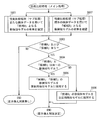
図4は、本実施形態に係る更新用検知モデル生成処理の流れの概要を示すフローチャートである。本実施形態に係る更新用検知モデル生成処理は、所定の環境のサイバー攻撃の検体データが検知モデル生成装置10に入力されたことを契機として実行される。
ステップS001では、サイバー攻撃の検体データの入力が受け付けられる。検体データ入力受付部22は、所定の種類の通信(ここでは、サイバー攻撃)を検知するための現検知モデルが用いられている所定の環境(例えば、ネットワーク監視装置20Aが設置されたローカルネットワーク)のサイバー攻撃の検体データの入力を受け付ける。検体データ入力受付部22は、入力されたサイバー攻撃の検体データを、新たな検体データとして、RAM13またはストレージ14に記録する。なお、本実施形態では、ネットワーク監視装置20Aが設置されたローカルネットワークを「環境A」と称し、ネットワーク監視装置20Aで用いられる更新用検知モデルの生成について説明する。なお、ここで受け付けられる検体データは、サイバー攻撃の有無について分類済みのデータであり、検体データには、正解ラベル(サイバー攻撃の有無を示す情報)が付されている。その後、処理はステップS002へ進む。
ステップS002では、特徴抽出処理が実行される。特徴抽出部23は、入力された新たな検体データから、新規の特徴を抽出する。特徴抽出処理の詳細については、図5を用いて後述する。その後、処理はステップS003へ進む。
ステップS003およびステップS004では、検体データ分割処理が実行され、分割の成否が判定される。検体データ分割部25は、新たな検体データを、機械学習用とテスト用とに分割し、また、検知モデル生成部26は、分割の過程で、新検知モデルを1つ生成する(S003)。即ち、本実施形態では、検体データをどのように機械学習用とテスト用とに分割するかが決定した時点で、少なくとも1つの新検知モデルが生成される。検体データ分割処理の詳細については、図6から図8を用いて後述する。ステップS004では、ステップS001で入力された新たな検体データの分割の成否が判定される。新たな検体データの分割に失敗した場合、本フローチャートに示された処理は終了する。一方、新たな検体データの分割に成功した場合、処理はステップS005およびステップS006.2からS006.mへ進む。
ステップS005では、既存の特徴を使用した検体データの変換が行われる。検体データ変換部24は、既存の特徴を使用して、全検体データ(既存の検体データ+新たな検体データ)を、機械学習アルゴリズムの入力データに適した形式に変換する。その後、処理はステップS007へ進む。
ステップS006.2からS006.mでは、既存の特徴および新規の特徴を使用した検体データの変換、および第二の新検知モデルの生成が行われる。なお、本実施形態において、ステップS006.2からS006.mの各処理は、単一のサーバーまたは複数のサーバーで並列に処理される。各サーバーで処理される第二の新検知モデル生成処理の詳細については、図9を用いて後述する。その後、処理はステップS007へ進む。
ステップS007およびステップS008では、性能比較処理が実行され、現検知モデルの置き換え対象となる新検知モデル(更新用検知モデル)が存在するか否かが判定される。性能比較部29は、これまでに生成された1または複数の新検知モデル(第二の新検知モデルを含む)と現検知モデルとを比較し、比較の結果に基づいて、現検知モデルを置き換えるための更新用検知モデルを決定する(ステップS007)。性能比較処理の詳細については、図10および図11を用いて後述する。性能比較処理の結果、現検知モデルの置き換え対象となる新検知モデル(更新用検知モデル)が存在しない場合、本フローチャートに示された処理は終了する。一方、性能比較処理の結果、現検知モデルの置き換え対象となる新検知モデル(更新用検知モデル)が存在する場合、処理はステップS009へ進む。
ステップS009では、データ管理処理が実行される。データ管理部21は、新たな検体データおよびその正解ラベル(サイバー攻撃の有無を示す情報)を、互いに関連づけて、環境識別子「環境A」のデータとして検体データ管理データベースに保存する。また、データ管理部21は、新規の特徴を、環境識別子「環境A」のデータとして特徴データ管理データベースに保存する。その後、処理はステップS010へ進む。
ステップS010では、更新用検知モデルがネットワーク監視装置20へ送信される。検知モデル送信部30は、現検知モデルの置き換え対象となる新検知モデル(更新用検知モデル)を、ネットワーク監視装置20へ送信する。そして、更新用検知モデルを受信したネットワーク監視装置20は、受信した更新用検知モデルを新たな現検知モデルとし、以降、新たな現検知モデルを用いて、サイバー攻撃を検知する。その後、本フローチャートに示された処理は終了する。
上記説明したような更新用検知モデル生成処理が実行されることで、限られた検体データを用いて、性能の高い検知モデルを効率的に生成することが可能となる。以下、上記フローチャートに登場する各ステップの詳細について、フローチャートを参照しながら説明する。
図5は、本実施形態に係る特徴抽出処理の流れの概要を示すフローチャートである。本フローチャートは、更新用検知モデル生成処理(図4を参照)のステップS002の処理を詳細に説明するためのものである。
ステップS101では、既存の検体データが取り出される。特徴抽出部23は、環境識別子が「共通」に該当する検体データおよび「環境A」に該当する検体データと正解ラベル(サイバー攻撃の有無を示す情報)を、検体データ管理データベースから取り出す。その後、処理はステップS102へ進む。
ステップS102では、既存の特徴が取り出される。特徴抽出部23は、環境識別子が「共通」に該当する検体データおよび「環境A」に該当する特徴データを、特徴データ管理データベースから取り出す。その後、処理はステップS103へ進む。
ステップS103では、新たな検体データの分解処理が行われる。特徴抽出部23は、分解ルールとして正規表現を利用するなどの方法で、新たな検体データの内容を単語毎に分解する。例えば、検体データがHTTPリクエストヘッダー群である場合、特徴抽出部23は、以下の正規表現を分解ルールとして用いて、リクエストヘッダー群の内容を、単語毎に分解することが出来る。
[a-zA-Z0-9:][a-zA-Z0-9_\\-:.]+\\b
その後、処理はステップS104へ進む。
[a-zA-Z0-9:][a-zA-Z0-9_\\-:.]+\\b
その後、処理はステップS104へ進む。
ステップS104では、新規の特徴が抽出される。特徴抽出部23は、新たな検体データと既存の特徴とを突き合わせることで、新たな検体データから新規の特徴(既存の特徴に存在しない特徴)を抽出する。その後、本フローチャートに示された処理は終了する。
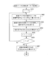
図6は、本実施形態に係る検体データ分割処理(メイン処理)の流れの概要を示すフローチャートである。本フローチャートは、更新用検知モデル生成処理(図4を参照)のステップS003の処理を詳細に説明するためのものである。
ステップS201では、既存の特徴および新規の特徴を使用した検体データの変換が行われる。検体データ変換部24は、既存の特徴および新規の特徴を使用して、全検体データ(既存の検体データ+新たな検体データ)を、機械学習アルゴリズムの入力データに適した形式に変換する。その後、処理はステップS202へ進む。
ステップS202では、変数が初期化される。検体データ分割部25は、処理に用いる各変数に初期値を設定する。具体的には、検体データ分割部25は、後述するステップS203からステップS212のループ処理における1ループ前の分割数の時に算出された平均Accuracy(Ma´)に0を、1ループ前の分割数の時に見積もられた残り時間(Tr´)に0を、分割数(n)に2を設定する。その後、処理はステップS203へ進む。
ステップS203では、検体データが分割される。検体データ分割部25は、新たな検体データをn個に分割する(検体データ分割処理(サブ処理A))。検体データ分割処理(サブ処理A)の詳細については、図7を用いて後述する。その後、処理はステップS204へ進む。
ステップS204およびステップS205では、分割が成功した場合に、検知モデルが生成され、平均Accuracy(Ma)が算出される。ステップS203における検体データ分割処理(サブ処理A)において分割に失敗した場合、本フローチャートに示された処理は終了する(分割失敗)。一方、分割に成功した場合、検知モデル生成部26は、n個の検知モデルを生成し、検体データ分割部25は、平均Accuracy(Ma)を算出する(検体データ分割処理(サブ処理B))。これは、新たな検体データをn分割した場合、Accuracy算出用に機械学習用検体データの分割グループを選択する方法はn通りあり、n個の検知モデルを生成できるためである。検知モデル評価部28は、n個の検知モデルの夫々についてAccuracyを算出し、検体データ分割部25は、その平均値を平均Accuracy(Ma)とする。検体データ分割処理(サブ処理B)の詳細については、図8を用いて後述する。その後、処理はステップS206へ進む。
ステップS206では、分割数nを増やしたことで平均Accuracyに所定以上の変化が生じたか否かが判定される。検体データ分割部25は、1ループ前の分割数の時に算出された平均Accuracy(Ma´)と、現在の分割数(n)の時に算出された平均Accuracy(Ma)との間に、所定以上の差(例えば、所定値よりも大きな差)があるか否かを判定する。本実施形態では、例えば、以下の数式を用いて判定を行う。
|Ma - Ma´| > 0.0001
即ち、この式では、平均Accuracyの差が0.01%以内であるか否かが判定される。この判定に用いられる所定値には、その他の値が採用されてもよい。
|Ma - Ma´| > 0.0001
即ち、この式では、平均Accuracyの差が0.01%以内であるか否かが判定される。この判定に用いられる所定値には、その他の値が採用されてもよい。
所定以上の差がある場合、分割数(換言すれば、機械学習用検体データの量)をより増やすことによる平均Accuracyの向上可能性が高いと判定し、処理はステップS207へ進む。一方、所定以上の差がない(同等である)場合、これ以上分割数(換言すれば、機械学習用検体データの量)を増やすことによる平均Accuracyの向上可能性は低く、1ループ前の分割数での検体データ分割が適正であると判定し、処理はステップ213へ進む。
本実施形態では、平均Accuracyに所定以上の変化がみられなくなるまで、分割数nを増やしながら(機械学習用検体データの量を増やしながら)、ステップS203からステップS206の分割処理が繰り返し実行される。これは、同様の特徴を持つ検体データを使用して検知モデルを生成する場合、はじめのうちは、機械学習用検体データの数を増やすことで、最も特徴的な規則性を見つけることにつながり、検知モデルの性能は比較的大きく向上するが、さらに数を増やし、学習効果が少なくなると、検知モデルの性能の増加はなだらか(または一定)になるためである。検体データ分割部25は、上記判定条件を用ることで、検知モデルの性能の増加がなだらか(または一定)になり始めた時点の学習用検体データの割合(学習用検体データの量)を特定し、これを検知モデルの生成に最低限必要な学習用検体データの割合(学習用検体データの量)とし、残りの検体データをテスト用検体データとする。
なお、本実施形態では、検体データの分割に、検体データを2のべき乗(2、4、8、16・・・)個のグループへ均等分割する方式を採用しているが、検体データの分割方式には、その他の方式が用いられてもよい。例えば、検体データ中の、機械学習用検体データとして用いられる検体データの量を一定量や一定割合ずつ増やしていく方式が採用されてもよい。
ステップS207からステップS209では、分割上限数(Nmax)が定義されている場合に、分割数(n)が上限に達したか否かが判定される。検体データ分割部25は、分割上限数(Nmax)が定義されているか否かを判定する(ステップS207)。分割上限数(Nmax)が定義されている場合、検体データ分割部25は、現在の分割数(n)を2倍した値を新たな分割数(n)として設定し、また、今回の処理で算出された平均Accuracy(Ma)の値を、1ループ前の分割数の時に算出された平均Accuracy(Ma´)として設定する(ステップS208)。そして、新たな分割数(n)が分割上限数(Nmax)を超える場合(ステップS209のYES)、本フローチャートに示された処理は終了する(分割失敗)。一方、新たな分割数(n)が分割上限数(Nmax)を超えない場合(ステップS209のNO)、処理はステップS203へ戻り、新たな分割数(n)を用いた検体データの分割が行われる。
分割上限数(Nmax)が未定義である場合、後述する、置き換え候補の検知モデル(更新用検知モデル)を確定させるまでの所要上限時間(Tmax)を超過しない限り、検体データ分割処理は続行される。なお、検知システムの導入環境の実情に柔軟に対応できるよう、分割上限数(Nmax)を任意に定義できる仕組みを備えてもよい。分割上限数(Nmax)が定義された場合、ステップS210からステップS212の処理は実行されないため、更新用検知モデルを確定させるまでの時間は所要上限時間(Tmax)に制約されない。
ステップS210からステップS212では、分割上限数(Nmax)が定義されていない場合に、処理に使用できる残り時間に基づいて、処理を継続するか否かが判定される。残り時間判定部31は、検体データ分割処理で使用できる残り時間(Tr)を見積もる(ステップS210)。
本実施形態では、以下の数式を用いて、検体データ分割処理をi回実行した時点の残り時間(Tr)を見積もる。
Tr = Tmax - (Tb + Ts + Ta)
Ta = t * (m / M)
ここで、(m / M)の値は小数点以下切り上げ
Tmax:更新用検知モデルを確定させるまでの所要上限時間[秒](特徴抽出処理から性能比較処理までが対象)
Tb:「検体データ分割処理」の直前までの所要時間[秒]
Ts:「検体データ分割処理」をi回実行した時点の所要時間[秒]
Ta:検知モデルの生成処理および検知性能比較処理の所要見積時間[秒]
t:i回目の検体データ分割処理における「1検知モデルの生成時間+Accuracy算出時間」の最大値[秒]
m:現検知モデルおよび「第二の新検知モデル生成処理2からmの処理」で生成する第二の新検知モデルの総数
M:第二の新検知モデルを並列で生成する際に使用するサーバーの数
なお、所要上限時間(Tmax)は、管理者によって任意に設定可能であってよい。
Tr = Tmax - (Tb + Ts + Ta)
Ta = t * (m / M)
ここで、(m / M)の値は小数点以下切り上げ
Tmax:更新用検知モデルを確定させるまでの所要上限時間[秒](特徴抽出処理から性能比較処理までが対象)
Tb:「検体データ分割処理」の直前までの所要時間[秒]
Ts:「検体データ分割処理」をi回実行した時点の所要時間[秒]
Ta:検知モデルの生成処理および検知性能比較処理の所要見積時間[秒]
t:i回目の検体データ分割処理における「1検知モデルの生成時間+Accuracy算出時間」の最大値[秒]
m:現検知モデルおよび「第二の新検知モデル生成処理2からmの処理」で生成する第二の新検知モデルの総数
M:第二の新検知モデルを並列で生成する際に使用するサーバーの数
なお、所要上限時間(Tmax)は、管理者によって任意に設定可能であってよい。
検体データ分割処理で使用できる残り時間(Tr)が見積もられると、残り時間判定部31は、1ループ前の分割数の時に見積もられた残り時間(Tr´)から新たに見積もられた残り時間(Tr)を減じた値を、処理見積時間(Tr´-Tr)とみなして、新たに見積もられた残り時間(Tr)が、処理見積時間(Tr´-Tr)よりも多いか否かを判定する(ステップS211)。具体的には、以下の等価な条件式の何れかを用いて判定することができる。
Tr >= Tr´ - Tr
Tr >= Tr´ / 2
但し、処理見積時間は、その他の方法で算出されてもよいし、判定条件にはその他の条件式が採用されてもよい。
Tr >= Tr´ - Tr
Tr >= Tr´ / 2
但し、処理見積時間は、その他の方法で算出されてもよいし、判定条件にはその他の条件式が採用されてもよい。
新たに見積もられた残り時間(Tr)が上記条件を満たさない場合、残り時間(Tr)の間にもう1回の分割が終わらない可能性が高いため、本フローチャートに示された処理は終了する(分割失敗)。一方、新たに見積もられた残り時間(Tr)が上記条件を満たす場合、検体データ分割部25は、現在の分割数(n)を2倍した値を新たな分割数(n)として設定し、今回の処理で算出された平均Accuracy(Ma)の値を、1ループ前の分割数の時に算出された平均Accuracy(Ma´)として設定し、また、今回の処理で見積もられた残り時間(Tr)の値を、1ループ前の分割数の時に見積もられた残り時間(Tr´)として設定する(ステップS212)。その後、処理はステップS203へ戻り、新たな分割数(n)を用いた検体データの分割が行われる。
ステップS213では、新検知モデルが決定される。ステップS206における判定処理で、所定以上の差がないと判定された場合(ステップS206のNO)、検知モデル生成部26は、平均AccuracyがMa´の検知モデル群のうち、最大のAccuracyを持つ検知モデルを新検知モデル1として採用し、当該新検知モデルに対応する機械学習用検知データ及びテスト用検知データの分割パターンを採用する。即ち、検知モデル生成部26は、これ以上分割数(換言すれば、機械学習用検体データの量)を増やすことによる平均Accuracyの向上可能性は低く、1ループ前の分割数での検体データ分割が適正であると判断し、1ループ前の分割数での検体データ分割による機械学習用検体データの量を用いて生成された検知モデルを、新検知モデル1として採用する。その後、本フローチャートに示された処理は終了する(分割成功)。
なお、上記説明したフローチャートでは、ステップS209またはステップS211で条件「Nmax < n」や「Tr < Tr´ / 2」を満たす場合、「分割失敗」として処理を終了しているが、上述の通り、検体データ分割部25および検知モデル生成部26は、処理見積時間が残り時間を超える場合、ここまでの処理で生成された検知モデルを用いて新検知モデルを決定してもよい。これは、これまで実行した結果の範囲でも、現検知モデルと同等以上の新検知モデルを生成できる可能性があるためである。この場合、処理はステップS213へ進み、検知モデル生成部26は、ここまでの処理で最大のAccuracyを持つ検知モデルを新検知モデルとして採用し、対応する分割パターンを採用する。
図7は、本実施形態に係る検体データ分割処理(サブ処理A)の流れの概要を示すフローチャートである。本フローチャートは、検体データ分割処理(メイン処理)(図6を参照)のステップS203の処理を詳細に説明するためのものである。
ステップS301では、新たな検体データの数が判定される。新たな検体データの数が分割数(n)よりも少ない場合、分割は実行できないため、本フローチャートに示された処理は終了する(分割失敗)。一方、新たな検体データの数が分割数(n)以上である場合、処理はステップS302へ進む。
ステップS302では、1分割グループあたりの検体データ数が算出される。検体データ分割部25は、「新たな検体データ」の数を分割数(n)で割ることで、1分割グループあたりの「新たな検体データ」の数を算出する。その後、処理はステップS303へ進む。
ステップS303では、各分割グループに、検体データが振り分けられる。検体データ分割部25は、分割グループ毎に、ステップS302で算出された1分割グループあたりの「新たな検体データ」の数だけ、検体データをランダムに選択することで、n個の分割グループを生成する。この際、各分割グループには、検体データが重複しないように割り当てられるものとする。その後、本フローチャートに示された処理は終了する(分割成功)。
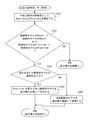
図8は、本実施形態に係る検体データ分割処理(サブ処理B)の流れの概要を示すフローチャートである。本フローチャートは、検体データ分割処理(メイン処理)(図6を参照)のステップS205の処理を詳細に説明するためのものである。
ステップS401では、変数が初期化される。検体データ分割部25は、処理に用いる各変数に初期値を設定する。具体的には、検体データ分割部25は、インデックス(i)に1を設定する。その後、処理はステップS402へ進む。
ステップS402では、分割グループがテスト用と機械学習用とに振り分けられる。検体データ分割部25は、n個に分割済みの「新たな検体データ」のうち、i番目の分割グループをテスト用に、残りを機械学習用にそれぞれ選択する。その後、処理はステップS403へ進む。
ステップS403では、検知モデルが生成される。検知モデル生成部26は、変換済みの機械学習用の全検体データと対応する正解ラベルとを入力データとして、機械学習アルゴリズム(例えば、ランダムフォレスト)を使用して検知モデルを生成する。その後、処理はステップS404へ進む。
ステップS404では、Accuracyが算出される。検知モデル評価部28は、変換済みのテスト用の「新たな検体データ」を検知モデルに入力し、Accuracyを求める。本実施形態では、Accuracyは、以下の数式を用いて算出される。
Accuracy = (TP + TN) / (TP + FN + FP + TN)
TP: サイバー攻撃「有」のテスト用検体データのうち、テスト対象の検知モデルを用いて検知された検知データの数
FN: サイバー攻撃「有」のテスト用検体データのうち、テスト対象の検知モデルを用いて検知されなかった検知データの数
FP: サイバー攻撃「無」のテスト用検体データのうち、テスト対象の検知モデルを用いてサイバー攻撃であると誤検知された検知データの数
TN: サイバー攻撃「無」のテスト用検体データのうち、テスト対象の検知モデルを用いて検知されなかった検知データの数
但し、Accuracyは、その他の方法で算出されてもよい。その後、処理はステップS405へ進む。
Accuracy = (TP + TN) / (TP + FN + FP + TN)
TP: サイバー攻撃「有」のテスト用検体データのうち、テスト対象の検知モデルを用いて検知された検知データの数
FN: サイバー攻撃「有」のテスト用検体データのうち、テスト対象の検知モデルを用いて検知されなかった検知データの数
FP: サイバー攻撃「無」のテスト用検体データのうち、テスト対象の検知モデルを用いてサイバー攻撃であると誤検知された検知データの数
TN: サイバー攻撃「無」のテスト用検体データのうち、テスト対象の検知モデルを用いて検知されなかった検知データの数
但し、Accuracyは、その他の方法で算出されてもよい。その後、処理はステップS405へ進む。
ステップS405およびステップS406では、インデックス(i)が更新され、処理を継続するか否かの判定が行われる。検体データ分割部25は、インデックス(i)を1インクリメントする(ステップS405)。そして、更新されたインデックス(i)は、分割数(n)と比較され、比較の結果インデックス(i)が分割数(n)以下である場合(ステップS406のNO)、処理はステップS402へ戻り、ステップS402からステップS405の処理が再実行される。即ち、ステップS402からステップS405の処理は、分割数(n)だけ繰り返し実行され、n個の検知モデルが生成される。一方、比較の結果インデックス(i)が分割数(n)より大きい場合(ステップS406のYES)、処理はステップS407へ進む。
ステップS407では、平均Accuracyが算出される。検体データ分割部25は、生成されたn個の検知モデルのAccuracyから、平均Accuracyを求める。その後、本フローチャートに示された処理は終了する。
図9は、本実施形態に係る第二の新検知モデル生成処理の流れの概要を示すフローチャートである。本フローチャートは、更新用検知モデル生成処理(図4を参照)のステップS006の処理を詳細に説明するためのものである。
ステップS501では、既存の特徴および新規の特徴を使用した検体データの変換が行われる。検体データ変換部24は、既存の特徴および新規の特徴を使用して、全検体データ(既存の検体データ+新たな検体データ)を、機械学習アルゴリズムの入力データに適した形式に変換する。その後、処理はステップS502へ進む。
ステップS502では、第二の新検知モデルが生成される。第二の検知モデル生成部27は、変換したデータおよび対応する正解ラベル(サイバー攻撃の有無を示す情報)を入力データとして、機械学習アルゴリズムを使用して検知モデルを生成する。この際用いられる機械学習アルゴリズムおよび機械学習用パラメータの少なくとも一方は、ステップS403における検知モデル生成で用いられたものと異なる。その後、本フローチャートに示された処理は終了する。
図10は、本実施形態に係る性能比較処理(メイン処理)の流れの概要を示すフローチャートである。本フローチャートは、更新用検知モデル生成処理(図4を参照)のステップS007の処理を詳細に説明するためのものである。なお、本実施形態に係るステップS601およびステップS602の処理は、単一のサーバーまたは複数のサーバーで並列に処理される。
ステップS601では、新たな検体データをテスト用検体データとして用いて、現検知モデルとの性能(検知精度)比較が行われる。性能比較部29は、変換済みの新たな検体データ(テスト用)を使って、現検知モデルの性能と同等以上の新検知モデル(第二の新検知モデルを含む)が存在するか確認する。性能比較処理(サブ処理)の詳細については、図11を用いて後述する。なお、ここで抽出された新検知モデルを、「候補A」とする。その後、処理はステップS603へ進む。
ステップS602では、検体データ管理データベースに蓄積されていた既存のテスト用検体データのうち、環境識別子が「共通」である検体データおよび「環境A」である検体データを用いて、現検知モデルとの性能比較が行われる。性能比較部29は、変換済みの既存の検体データ(テスト用)を使って、現検知モデルの性能と同等以上の新検知モデル(第二の新検知モデルを含む)が存在するか確認する。性能比較処理(サブ処理)の詳細については、図11を用いて後述する。なお、ここで抽出された新検知モデルを、「候補B」とする。その後、処理はステップS603へ進む。
ステップS603では、「候補A」および「候補B」が決定されたか否かが判定される。性能比較処理(サブ処理)の結果、「候補A」に該当する新検知モデルおよび「候補B」に該当する新検知モデルが何れか一方でも存在しない場合、本フローチャートに示された処理は終了する(置き換え対象なし)。一方、性能比較処理(サブ処理)の結果、「候補A」に該当する新検知モデルおよび「候補B」に該当する新検知モデルが存在する場合、処理はステップS604へ進む。
ステップS604からステップS606では、更新用検知モデルが決定される。「候補A」と「候補B」とが同一の新検知モデルである場合、性能比較部29は、当該新検知モデルを、更新用検知モデルとして採用する(ステップS605)。一方、「候補A」と「候補B」とが異なる新検知モデルである場合、性能比較部29は、「候補A」の新検知モデルを、更新用検知モデルとして採用する(ステップS606)。これは、新たな検体データに係る攻撃等を検知できる検知モデルを優先的に採用するためである。その後、本フローチャートに示された処理は終了する(置き換え対象決定)。
図11は、本実施形態に係る性能比較処理(サブ処理)の流れの概要を示すフローチャートである。本フローチャートは、性能比較処理(メイン処理)(図10を参照)のステップS601またはステップS602の処理を詳細に説明するためのものである。
ステップS701では、性能比較用の評価値が算出される。性能比較部29は、変換済みのテスト用検体データを使用して、現検知モデルおよび新検知モデルのサイバー攻撃の検知率(以下、「Recall」と称する)および検知結果の正答率(以下、「Precision」と称する)を求める。本実施形態では、RecallおよびPrecisionは、以下の数式を用いて算出される。
Recall = TP / (TP + FN)
Precision = TP / (TP + FP)
TP: サイバー攻撃「有」のテスト用検体データのうち、テスト対象の検知モデルを用いて検知された検知データの数
FN: サイバー攻撃「有」のテスト用検体データのうち、テスト対象の検知モデルを用いて検知されなかった検知データの数
FP: サイバー攻撃「無」のテスト用検体データのうち、テスト対象の検知モデルを用いてサイバー攻撃であると誤検知された検知データの数
TN: サイバー攻撃「無」のテスト用検体データのうち、テスト対象の検知モデルを用いて検知されなかった検知データの数
但し、RecallおよびPrecisionは、その他の方法で算出されてもよい。その後、処理はステップS702へ進む。
Recall = TP / (TP + FN)
Precision = TP / (TP + FP)
TP: サイバー攻撃「有」のテスト用検体データのうち、テスト対象の検知モデルを用いて検知された検知データの数
FN: サイバー攻撃「有」のテスト用検体データのうち、テスト対象の検知モデルを用いて検知されなかった検知データの数
FP: サイバー攻撃「無」のテスト用検体データのうち、テスト対象の検知モデルを用いてサイバー攻撃であると誤検知された検知データの数
TN: サイバー攻撃「無」のテスト用検体データのうち、テスト対象の検知モデルを用いて検知されなかった検知データの数
但し、RecallおよびPrecisionは、その他の方法で算出されてもよい。その後、処理はステップS702へ進む。
ステップS702では、算出された評価値を用いた性能比較が行われる。具体的には、性能比較部29は、算出された評価値が「現検知モデルのRecall <= 新検知モデルのRecallかつ、現検知モデルのPrecision <= 新検知モデルのPrecision」という条件を満たすか否かを判定する。判定の結果、評価値が条件を満たさない場合、本フローチャートに示された処理は終了する(置き換え候補なし)。一方、判定の結果、評価値が条件を満たす場合、処理はステップS703へ進む。
ステップS703からステップS705では、条件を満たす新検知モデルから、置き換え候補が決定される。ここで決定される候補は、本フローチャートの処理がステップS601から呼び出されている場合には「候補A」、本フローチャートの処理がステップS602から呼び出されている場合には「候補B」である。条件を満たす新検知モデルが複数存在する場合(ステップS703のYES)、性能比較部29は、Precisionが最も大きい新検知モデルを、最も高い性能を持つ検知モデルとして採用し、置き換え候補(「候補A」または「候補B」)とする(ステップS704)。一方、条件を満たす新検知モデルが1つである場合、性能比較部29は、該当する新検知モデルを、最も高い性能を持つ検知モデルとして採用し、置き換え候補(「候補A」または「候補B」)とする。その後、本フローチャートに示された処理は終了する(置き換え候補決定)。
即ち、本実施形態において、性能比較部29は、所定の種類の通信の検知率(実際の攻撃が攻撃として検知される割合)および所定の種類の通信であるとの検知結果の正答率(攻撃として検知されたものが、実際の攻撃である割合)の双方に基づいて、性能比較を行う。これは、正常な通信をサイバー攻撃と検知してしまった場合、正常な通信が制限、または、遮断されることにつながり、運用継続を維持できなくなるため、サイバー攻撃を検知できる能力が高いことが重要であると同時に、正常な通信をサイバー攻撃と誤認することも避ける必要があるためである。本実施形態によれば、上記のような性能比較が行われるため、安全性の向上の側面からの検知漏れの評価(検知率)と、運用継続性の側面からの正確性の評価(正答率)との双方の側面からの性能比較が行われ、現検知モデルの置き換え対象として最適な新検知モデルを選択することが可能となる。
<効果>
本実施形態に係る情報処理装置、方法およびプログラムによれば、検知システムの検知ロジック更新を省力化できると共に、継続的な更新が容易になる。即ち、限られた検体データを用いて、性能の高い検知モデルを効率的に生成することが可能となり、検知ロジックを更新する手間を軽減することができる。また、「運用継続性の維持」と「安全性の向上」とを両立した検知モデルを生成可能であることから、サービスレベルの維持に加えて、サイバー攻撃に対する安全性の向上にも対応できる。
本実施形態に係る情報処理装置、方法およびプログラムによれば、検知システムの検知ロジック更新を省力化できると共に、継続的な更新が容易になる。即ち、限られた検体データを用いて、性能の高い検知モデルを効率的に生成することが可能となり、検知ロジックを更新する手間を軽減することができる。また、「運用継続性の維持」と「安全性の向上」とを両立した検知モデルを生成可能であることから、サービスレベルの維持に加えて、サイバー攻撃に対する安全性の向上にも対応できる。
1 システム
10 検知モデル生成装置
20 ネットワーク監視装置
90 ノード
10 検知モデル生成装置
20 ネットワーク監視装置
90 ノード
Claims (18)
- 所定の種類の通信に係る新たな検体データの入力を受け付ける検体データ入力受付手段と、
前記新たな検体データを、互いに異なる複数の分割パターンを用いて機械学習用検体データとテスト用検体データに分割する検体データ分割手段と、
前記機械学習用検体データを用いた機械学習によって、分割パターン毎に、前記所定の種類の通信を検知するための検知モデルを生成する検知モデル生成手段と、
前記テスト用検体データを用いて前記検知モデルの性能を評価する検知モデル評価手段と、を備え、
前記検知モデル生成手段は、生成された検知モデルのうち最も性能の高いモデルを新検知モデルとする、
情報処理装置。 - 前記検体データ分割手段は、第一の分割パターンを用いて生成された検知モデルの性能と、該第一の分割パターンより機械学習用検体データを増やした第二の分割パターンを用いて生成された検知モデルの性能との間に所定以上の差がある場合、該第二の分割パターンよりも機械学習用検体データを増やした第三の分割パターンを更に生成する、
請求項1に記載の情報処理装置。 - 前記検体データ分割手段は、第一の分割パターンを用いて生成された検知モデルの性能に比べて、該第一の分割パターンより機械学習用検体データを増やした第二の分割パターンを用いて生成された検知モデルの性能が所定以上優れている場合、該第二の分割パターンよりも機械学習用検体データを増やした第三の分割パターンを更に生成する、
請求項1に記載の情報処理装置。 - 前記所定の種類の通信を検知するための現検知モデルの生成に用いられた既存の特徴および既存の検体データを保存するデータ管理手段を更に備え、
前記検知モデル生成手段は、前記機械学習用検体データおよび前記既存の検体データを用いた機械学習によって分割パターン毎に検知モデルを生成する、
請求項1から3の何れか一項に記載の情報処理装置。 - 前記新たな検体データから、前記既存の特徴とは異なる新規の特徴を抽出する特徴抽出手段と、
前記既存の特徴および前記新規の特徴を使用して、既存の検体データおよび前記新たな検体データを、機械学習のための所定のデータ形式に変換する、検体データ変換手段を更に備え、
前記検知モデル生成手段は、前記所定のデータ形式に変換された検体データを用いた機械学習によって検知モデルを生成する、
請求項4に記載の情報処理装置。 - 前記データ管理手段は、前記新たな検体データおよび前記新規の特徴を、前記新検知モデルの生成後に、既存の検体データおよび既存の特徴として蓄積する、
請求項5に記載の情報処理装置。 - 前記検体データ入力受付手段は、前記所定の種類の通信を検知するための現検知モデルが用いられている所定の環境に係る新たな検体データの入力を受け付け、
前記データ管理手段は、前記新検知モデルの生成後に、前記新たな検体データおよび前記新規の特徴を、前記所定の環境に関連づけて蓄積することで、該所定の環境に関する既存の検体データおよび既存の特徴とする、
請求項5に記載の情報処理装置。 - 検体データ変換手段は、Bag-of-Words方式で検体データを変換し、
検知モデル生成手段は、ランダムフォレスト方式の機械学習によって検知モデルを生成する、
請求項5から7の何れか一項に記載の情報処理装置。 - 検体データ変換手段は、検体データ内のデータを各特徴に対応する一意の数値に変換する方法で検体データを変換し、
検知モデル生成手段は、ニューラルネットワーク方式の機械学習によって検知モデルを生成する、
請求項5から7の何れか一項に記載の情報処理装置。 - 前記所定の種類の通信を検知するための現検知モデルと前記新検知モデルの性能を比較し、現検知モデルと概略同等かまたは現検知モデルよりも大きい性能を有する前記新検知モデルを、現検知モデルを置き換える更新用検知モデルに決定する性能比較手段を更に備える、
請求項1から9の何れか一項に記載の情報処理装置。 - 前記検知モデル生成手段とは異なる機械学習アルゴリズムまたは異なる機械学習用パラメータを用いて第二の新検知モデルを生成する第二の検知モデル生成手段を更に備え、
前記性能比較手段は、前記現検知モデル、前記新検知モデルおよび前記第二の新検知モデルの性能を比較し、現検知モデルと概略同等かまたは現検知モデルよりも大きい性能を有する何れかの前記新検知モデルまたは前記第二の新検知モデルを、現検知モデルを置き換える更新用検知モデルとする、
請求項10に記載の情報処理装置。 - 前記性能比較手段は、前記所定の種類の通信の検知率および前記所定の種類の通信であるとの検知結果の正答率の双方に基づいて、前記性能比較を行う、
請求項10または11に記載の情報処理装置。 - 前記更新用検知モデルを検知装置に送信し、該検知装置において用いられる検知モデルを更新させる、検知モデル送信手段を更に備える、
請求項10から12の何れか一項に記載の情報処理装置。 - 前記検体データ分割手段が異なる分割パターンを用いて前記新たな検体データを分割する毎に、前記更新用検知モデルが得られるまでの予め設定された上限時間までの残り時間と処理見積時間を計算し、該処理見積時間が残り時間を超えるか否かを判定する残り時間判定手段を更に備え、
前記検体データ分割手段は、前記処理見積時間が残り時間を超える場合、処理を終了する、
請求項10から13の何れか一項に記載の情報処理装置。 - 前記検知モデル生成手段は、前記処理見積時間が残り時間を超える場合、これまでの処理で生成された検知モデルを用いて前記新検知モデルを決定する、
請求項14に記載の情報処理装置。 - 前記所定の種類の通信は、所定の種類の悪意の通信である、
請求項1から14の何れか一項に記載の情報処理装置。 - コンピューターが、
所定の種類の通信に係る新たな検体データの入力を受け付ける検体データ入力受付と、
前記新たな検体データを、互いに異なる複数の分割パターンを用いて機械学習用検体データとテスト用検体データに分割する検体データ分割と、
前記機械学習用検体データを用いた機械学習によって、分割パターン毎に、前記所定の種類の通信を検知するための検知モデルを生成する検知モデル生成と、
前記テスト用検体データを用いて前記検知モデルの性能を評価する検知モデル評価と、を実行し、
前記検知モデル生成では、生成された検知モデルのうち最も性能の高いモデルが新検知モデルとされる、
方法。 - コンピューターを、
所定の種類の通信に係る新たな検体データの入力を受け付ける検体データ入力受付手段と、
前記新たな検体データを、互いに異なる複数の分割パターンを用いて機械学習用検体データとテスト用検体データに分割する検体データ分割手段と、
前記機械学習用検体データを用いた機械学習によって、分割パターン毎に、前記所定の種類の通信を検知するための検知モデルを生成する検知モデル生成手段と、
前記テスト用検体データを用いて前記検知モデルの性能を評価する検知モデル評価手段と、として機能させ、
前記検知モデル生成手段は、生成された検知モデルのうち最も性能の高いモデルを新検知モデルとする、
プログラム。
Priority Applications (1)
| Application Number | Priority Date | Filing Date | Title |
|---|---|---|---|
| PCT/JP2016/085227 WO2018096685A1 (ja) | 2016-11-28 | 2016-11-28 | 情報処理装置、方法およびプログラム |
Applications Claiming Priority (1)
| Application Number | Priority Date | Filing Date | Title |
|---|---|---|---|
| PCT/JP2016/085227 WO2018096685A1 (ja) | 2016-11-28 | 2016-11-28 | 情報処理装置、方法およびプログラム |
Publications (1)
| Publication Number | Publication Date |
|---|---|
| WO2018096685A1 true WO2018096685A1 (ja) | 2018-05-31 |
Family
ID=62195843
Family Applications (1)
| Application Number | Title | Priority Date | Filing Date |
|---|---|---|---|
| PCT/JP2016/085227 Ceased WO2018096685A1 (ja) | 2016-11-28 | 2016-11-28 | 情報処理装置、方法およびプログラム |
Country Status (1)
| Country | Link |
|---|---|
| WO (1) | WO2018096685A1 (ja) |
Cited By (3)
| Publication number | Priority date | Publication date | Assignee | Title |
|---|---|---|---|---|
| JP2020077066A (ja) * | 2018-11-05 | 2020-05-21 | 株式会社リコー | 学習装置および学習方法 |
| JP2021526687A (ja) * | 2018-06-01 | 2021-10-07 | エヌティーティー セキュリティー コーポレイション | 効率的なラベル伝搬のためのアンサンブルベースのデータキュレーションパイプライン |
| JP2025504828A (ja) * | 2022-01-18 | 2025-02-19 | パロ アルト ネットワークス,インコーポレイテッド | 悪意のあるコマンドを検出し、トラフィックを制御するためのディープラーニングパイプライン |
Citations (3)
| Publication number | Priority date | Publication date | Assignee | Title |
|---|---|---|---|---|
| US20100082513A1 (en) * | 2008-09-26 | 2010-04-01 | Lei Liu | System and Method for Distributed Denial of Service Identification and Prevention |
| US20150135318A1 (en) * | 2013-11-12 | 2015-05-14 | Macau University Of Science And Technology | Method of detecting intrusion based on improved support vector machine |
| US20150193697A1 (en) * | 2014-01-06 | 2015-07-09 | Cisco Technology, Inc. | Cross-validation of a learning machine model across network devices |
-
2016
- 2016-11-28 WO PCT/JP2016/085227 patent/WO2018096685A1/ja not_active Ceased
Patent Citations (3)
| Publication number | Priority date | Publication date | Assignee | Title |
|---|---|---|---|---|
| US20100082513A1 (en) * | 2008-09-26 | 2010-04-01 | Lei Liu | System and Method for Distributed Denial of Service Identification and Prevention |
| US20150135318A1 (en) * | 2013-11-12 | 2015-05-14 | Macau University Of Science And Technology | Method of detecting intrusion based on improved support vector machine |
| US20150193697A1 (en) * | 2014-01-06 | 2015-07-09 | Cisco Technology, Inc. | Cross-validation of a learning machine model across network devices |
Cited By (5)
| Publication number | Priority date | Publication date | Assignee | Title |
|---|---|---|---|---|
| JP2021526687A (ja) * | 2018-06-01 | 2021-10-07 | エヌティーティー セキュリティー コーポレイション | 効率的なラベル伝搬のためのアンサンブルベースのデータキュレーションパイプライン |
| JP2020077066A (ja) * | 2018-11-05 | 2020-05-21 | 株式会社リコー | 学習装置および学習方法 |
| JP7196542B2 (ja) | 2018-11-05 | 2022-12-27 | 株式会社リコー | 学習装置および学習方法 |
| JP2025504828A (ja) * | 2022-01-18 | 2025-02-19 | パロ アルト ネットワークス,インコーポレイテッド | 悪意のあるコマンドを検出し、トラフィックを制御するためのディープラーニングパイプライン |
| JP7794988B2 (ja) | 2022-01-18 | 2026-01-06 | パロ アルト ネットワークス,インコーポレイテッド | 悪意のあるコマンドを検出し、トラフィックを制御するためのディープラーニングパイプライン |
Similar Documents
| Publication | Publication Date | Title |
|---|---|---|
| US10686807B2 (en) | Intrusion detection system | |
| US11818155B2 (en) | Cognitive information security using a behavior recognition system | |
| CN112019575B (zh) | 数据包处理方法、装置、计算机设备以及存储介质 | |
| CN108429651B (zh) | 流量数据检测方法、装置、电子设备及计算机可读介质 | |
| EP2725512B1 (en) | System and method for malware detection using multi-dimensional feature clustering | |
| US8260914B1 (en) | Detecting DNS fast-flux anomalies | |
| US10355949B2 (en) | Behavioral network intelligence system and method thereof | |
| CN112448947B (zh) | 网络异常确定方法、设备及存储介质 | |
| US10326736B2 (en) | Feature-based classification of individual domain queries | |
| US20160226737A1 (en) | System and method for anomaly detection in information technology operations | |
| CN109951491A (zh) | 网络攻击检测方法、装置、设备及存储介质 | |
| KR102156891B1 (ko) | 인공지능 머신러닝 행위 기반 웹 프로토콜 분석을 통한 웹 공격 탐지 및 차단 시스템 및 방법 | |
| CN113452676A (zh) | 一种检测器分配方法和物联网检测系统 | |
| US20250287210A1 (en) | Systems and methods for cellular network security slicing | |
| WO2018096685A1 (ja) | 情報処理装置、方法およびプログラム | |
| KR102609592B1 (ko) | IoT 시스템의 비정상행위 탐지 방법 및 그 장치 | |
| WO2023180944A1 (en) | System and method for device attribute identification based on host configuration protocols | |
| Tang et al. | PeakSAX: Real-time monitoring and mitigation system for LDoS attack in SDN | |
| CN109361658B (zh) | 基于工控行业的异常流量信息存储方法、装置及电子设备 | |
| KR20180130295A (ko) | 통신망의 장애를 예측하는 장치 및 방법 | |
| US12009986B2 (en) | Proactive inspection technique for improved classification | |
| CN111669411A (zh) | 一种工控设备异常检测方法及系统 | |
| CN105099799B (zh) | 僵尸网络检测方法和控制器 | |
| JP6652912B2 (ja) | ネットワーク装置および異常検知システム | |
| CN115913587B (zh) | 一种攻击检测方法、装置、设备和计算机存储介质 |
Legal Events
| Date | Code | Title | Description |
|---|---|---|---|
| 121 | Ep: the epo has been informed by wipo that ep was designated in this application |
Ref document number: 16922139 Country of ref document: EP Kind code of ref document: A1 |
|
| NENP | Non-entry into the national phase |
Ref country code: DE |
|
| 122 | Ep: pct application non-entry in european phase |
Ref document number: 16922139 Country of ref document: EP Kind code of ref document: A1 |
|
| NENP | Non-entry into the national phase |
Ref country code: JP |