WO2018096639A1 - Image processing device, microscope system, image processing method, and program - Google Patents
Image processing device, microscope system, image processing method, and program Download PDFInfo
- Publication number
- WO2018096639A1 WO2018096639A1 PCT/JP2016/084866 JP2016084866W WO2018096639A1 WO 2018096639 A1 WO2018096639 A1 WO 2018096639A1 JP 2016084866 W JP2016084866 W JP 2016084866W WO 2018096639 A1 WO2018096639 A1 WO 2018096639A1
- Authority
- WO
- WIPO (PCT)
- Prior art keywords
- image
- microscope
- enlarged
- microscope image
- processing apparatus
- Prior art date
Links
- 238000012545 processing Methods 0.000 title claims abstract description 145
- 238000003672 processing method Methods 0.000 title claims description 13
- 238000001000 micrograph Methods 0.000 claims abstract description 571
- 238000000034 method Methods 0.000 claims description 76
- 238000005286 illumination Methods 0.000 claims description 9
- 238000009826 distribution Methods 0.000 claims description 7
- 238000004590 computer program Methods 0.000 claims description 3
- 230000008569 process Effects 0.000 description 35
- 238000010586 diagram Methods 0.000 description 33
- 239000003550 marker Substances 0.000 description 26
- 238000003384 imaging method Methods 0.000 description 19
- 230000000052 comparative effect Effects 0.000 description 17
- 230000004048 modification Effects 0.000 description 7
- 238000012986 modification Methods 0.000 description 7
- 238000006243 chemical reaction Methods 0.000 description 6
- 230000003287 optical effect Effects 0.000 description 5
- 239000000284 extract Substances 0.000 description 4
- 238000000386 microscopy Methods 0.000 description 4
- 239000003153 chemical reaction reagent Substances 0.000 description 3
- 230000008859 change Effects 0.000 description 2
- 238000004891 communication Methods 0.000 description 2
- 230000000881 depressing effect Effects 0.000 description 2
- 238000001514 detection method Methods 0.000 description 2
- 239000003814 drug Substances 0.000 description 2
- 229940079593 drug Drugs 0.000 description 2
- 239000000428 dust Substances 0.000 description 2
- 239000011521 glass Substances 0.000 description 2
- 230000004044 response Effects 0.000 description 2
- 230000002194 synthesizing effect Effects 0.000 description 2
- 230000002123 temporal effect Effects 0.000 description 2
- 238000002834 transmittance Methods 0.000 description 2
- 210000004046 cell surface extension Anatomy 0.000 description 1
- 230000000295 complement effect Effects 0.000 description 1
- 239000006059 cover glass Substances 0.000 description 1
- 230000002950 deficient Effects 0.000 description 1
- 238000006073 displacement reaction Methods 0.000 description 1
- 239000010419 fine particle Substances 0.000 description 1
- 239000007850 fluorescent dye Substances 0.000 description 1
- PCHJSUWPFVWCPO-UHFFFAOYSA-N gold Chemical compound [Au] PCHJSUWPFVWCPO-UHFFFAOYSA-N 0.000 description 1
- 239000010931 gold Substances 0.000 description 1
- 229910052737 gold Inorganic materials 0.000 description 1
- 230000010365 information processing Effects 0.000 description 1
- 230000003834 intracellular effect Effects 0.000 description 1
- 239000004973 liquid crystal related substance Substances 0.000 description 1
- 230000004807 localization Effects 0.000 description 1
- 230000002438 mitochondrial effect Effects 0.000 description 1
- 238000012544 monitoring process Methods 0.000 description 1
- 230000000877 morphologic effect Effects 0.000 description 1
- 230000000737 periodic effect Effects 0.000 description 1
- 238000003825 pressing Methods 0.000 description 1
- 238000009877 rendering Methods 0.000 description 1
- 239000000758 substrate Substances 0.000 description 1
- 230000000007 visual effect Effects 0.000 description 1
Images


Classifications
-
- G—PHYSICS
- G06—COMPUTING; CALCULATING OR COUNTING
- G06T—IMAGE DATA PROCESSING OR GENERATION, IN GENERAL
- G06T7/00—Image analysis
- G06T7/0002—Inspection of images, e.g. flaw detection
- G06T7/0012—Biomedical image inspection
- G06T7/0014—Biomedical image inspection using an image reference approach
- G06T7/0016—Biomedical image inspection using an image reference approach involving temporal comparison
-
- G—PHYSICS
- G06—COMPUTING; CALCULATING OR COUNTING
- G06T—IMAGE DATA PROCESSING OR GENERATION, IN GENERAL
- G06T7/00—Image analysis
- G06T7/70—Determining position or orientation of objects or cameras
-
- G—PHYSICS
- G02—OPTICS
- G02B—OPTICAL ELEMENTS, SYSTEMS OR APPARATUS
- G02B21/00—Microscopes
- G02B21/36—Microscopes arranged for photographic purposes or projection purposes or digital imaging or video purposes including associated control and data processing arrangements
- G02B21/365—Control or image processing arrangements for digital or video microscopes
- G02B21/367—Control or image processing arrangements for digital or video microscopes providing an output produced by processing a plurality of individual source images, e.g. image tiling, montage, composite images, depth sectioning, image comparison
-
- G—PHYSICS
- G06—COMPUTING; CALCULATING OR COUNTING
- G06F—ELECTRIC DIGITAL DATA PROCESSING
- G06F18/00—Pattern recognition
- G06F18/20—Analysing
- G06F18/22—Matching criteria, e.g. proximity measures
-
- G—PHYSICS
- G06—COMPUTING; CALCULATING OR COUNTING
- G06T—IMAGE DATA PROCESSING OR GENERATION, IN GENERAL
- G06T3/00—Geometric image transformations in the plane of the image
- G06T3/20—Linear translation of whole images or parts thereof, e.g. panning
-
- G—PHYSICS
- G06—COMPUTING; CALCULATING OR COUNTING
- G06T—IMAGE DATA PROCESSING OR GENERATION, IN GENERAL
- G06T3/00—Geometric image transformations in the plane of the image
- G06T3/40—Scaling of whole images or parts thereof, e.g. expanding or contracting
-
- G—PHYSICS
- G06—COMPUTING; CALCULATING OR COUNTING
- G06T—IMAGE DATA PROCESSING OR GENERATION, IN GENERAL
- G06T3/00—Geometric image transformations in the plane of the image
- G06T3/60—Rotation of whole images or parts thereof
-
- G—PHYSICS
- G06—COMPUTING; CALCULATING OR COUNTING
- G06T—IMAGE DATA PROCESSING OR GENERATION, IN GENERAL
- G06T5/00—Image enhancement or restoration
- G06T5/50—Image enhancement or restoration using two or more images, e.g. averaging or subtraction
-
- G—PHYSICS
- G06—COMPUTING; CALCULATING OR COUNTING
- G06T—IMAGE DATA PROCESSING OR GENERATION, IN GENERAL
- G06T2207/00—Indexing scheme for image analysis or image enhancement
- G06T2207/10—Image acquisition modality
- G06T2207/10056—Microscopic image
-
- G—PHYSICS
- G06—COMPUTING; CALCULATING OR COUNTING
- G06T—IMAGE DATA PROCESSING OR GENERATION, IN GENERAL
- G06T2207/00—Indexing scheme for image analysis or image enhancement
- G06T2207/20—Special algorithmic details
- G06T2207/20212—Image combination
-
- G—PHYSICS
- G06—COMPUTING; CALCULATING OR COUNTING
- G06T—IMAGE DATA PROCESSING OR GENERATION, IN GENERAL
- G06T2207/00—Indexing scheme for image analysis or image enhancement
- G06T2207/30—Subject of image; Context of image processing
- G06T2207/30004—Biomedical image processing
- G06T2207/30024—Cell structures in vitro; Tissue sections in vitro
-
- H—ELECTRICITY
- H04—ELECTRIC COMMUNICATION TECHNIQUE
- H04N—PICTORIAL COMMUNICATION, e.g. TELEVISION
- H04N7/00—Television systems
- H04N7/18—Closed-circuit television [CCTV] systems, i.e. systems in which the video signal is not broadcast
- H04N7/183—Closed-circuit television [CCTV] systems, i.e. systems in which the video signal is not broadcast for receiving images from a single remote source
Definitions
- the present invention relates to an image processing apparatus, a microscope system, an image processing method, and a program.
- Patent Document 1 Japanese Patent Laid-Open No. 2015-208539
- the image processing apparatus includes a reception unit that receives designation of position information in at least a part of the first microscope image, and a part of the first microscope image based on the position information.
- An image generation unit that outputs a first enlarged image obtained by enlarging the area and a second enlarged image related to the first enlarged image in the second microscope image;
- an image processing method that accepts designation of position information in at least a part of the first microscope image, and a partial area of the first microscope image based on the position information. And outputting a first enlarged image obtained by enlarging the first enlarged image and a second enlarged image related to the first enlarged image in the second microscope image.
- a computer program that accepts designation of position information in at least a part of the first microscope image on the computer, and a part of the first microscope image based on the position information.
- a first enlarged image obtained by enlarging the region and a second enlarged image related to the first enlarged image in the second microscope image are output.
- FIG. 1 is a block diagram of a microscope system 100.
- FIG. The image displayed on the display apparatus 170 is shown.
- the image displayed on the display apparatus 170 is shown.
- 2 is a diagram illustrating a concept of processing in the image processing apparatus 101.
- FIG. 2 is a diagram illustrating a concept of processing in the image processing apparatus 101.
- FIG. 2 is a diagram illustrating a concept of processing in the image processing apparatus 101.
- FIG. 2 is a diagram illustrating a concept of processing in the image processing apparatus 101.
- FIG. The image displayed on the display apparatus 170 is shown.
- the image displayed on the display apparatus 170 is shown.
- 2 is a diagram illustrating a concept of processing in the image processing apparatus 101.
- FIG. 2 is a diagram illustrating a concept of processing in the image processing apparatus 101.
- FIG. 2 is a diagram illustrating a concept of processing in the image processing apparatus 101.
- FIG. 2 is a diagram illustrating a concept of processing in the image processing apparatus 101
- FIG. 3 is a flowchart illustrating a processing procedure in the image processing apparatus 101. It is a figure explaining the other example of step S102 of FIG. It is a figure explaining the further another example of step S102 of FIG. 1 is a block diagram of a microscope system 105. FIG. It is a figure explaining other combinations of a microscope picture. It is a figure explaining other combination of a microscope picture. A state where the first enlarged image 411 and the second enlarged image 412 are displayed on the display device 170 is shown. It is a figure explaining the other example using a time lapse image.
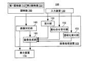
- FIG. 10 is a block diagram of a microscope system 100 including another image processing apparatus 102.
- FIG. 4 is a flowchart illustrating a procedure for executing processing in the image processing apparatus 102. It is a figure explaining the process which receives the scanning on the 1st microscope image 401 and the 2nd microscope image 402.
- FIG. 10 is a block diagram of another image processing apparatus 103. It is a figure explaining the process of the image processing apparatus. A state in which the superimposed image 414 is displayed is shown.
- 3 is a flowchart showing an operation procedure of the image processing apparatus 103. It is a figure explaining other operation
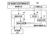
- FIG. 1 is a block diagram of a microscope system 100 including an image processing apparatus 101.
- the microscope system 100 includes a microscope 700, an input device 130, an image processing device 101, and a display device 170.
- the input device 130 is operated when an instruction from the user is input to the image processing device 101.
- an existing general-purpose input device such as a pointing device such as a mouse, a keyboard, or a touch panel is used.
- the input device 130 is used for input to the image processing apparatus 101, but an input device 130 installed for operating the first microscope 110 and the second microscope 120 may also be used.
- the display device 170 is a liquid crystal display panel or the like, and displays the display image output from the image processing device 101 in a state where the user can visually recognize the display image.
- the display device 170 may also be a display device provided for the first microscope 110, the second microscope 120, or the like for the purpose of displaying an image.
- the image processing apparatus 101 includes an image correspondence unit 140, a reception unit 150, and an image generation unit 160.
- the image processing apparatus 101 is configured by a general-purpose information processing apparatus controlled by a program that executes image processing to be described later.
- the image processing apparatus 101 processes the microscope image data acquired from the microscope 700 and generates an image to be displayed on the display device 170.
- the microscope 700 includes a first microscope 710 and a second microscope 720 that capture images of specimens using different microscope methods.
- the first microscope 710 and the second microscope 720 share at least part of the optical system in both microscopes (that is, at least part of the optical axes in both microscopes are coaxial).
- the first microscope 710 and the second microscope 720 may be optical systems in which the optical systems in both microscopes are independent.
- the first microscope 710 images a specimen by a SIM (Structured Illumination Microscope).
- the SIM illuminates the specimen with structured illumination having a periodic illumination pattern, and generates a super-resolution microscope image representing the microstructure of the specimen smaller than the illumination light wavelength based on interference fringes generated in the specimen image.
- This super-resolution microscope image is generated by reconstructing a plurality of images obtained by illuminating the specimen by changing the direction and position of the illumination pattern of structured illumination, respectively, by arithmetic processing.
- the expression “reconstruction” is hereinafter simply referred to as generation or imaging.
- the second microscope 720 images the specimen by STORM (Stochastic Optical Reconstruction Microscopy).
- STORM can reconstruct a fluorescent image (super-resolution microscope image) with a resolution higher than the wavelength of the illumination light by superimposing position information of fluorescent dyes detected with high accuracy from a plurality of fluorescent images.
- the expression “reconstruction” is hereinafter simply referred to as generation or imaging.
- the microscope 700 images the observation region including at least a part of the specimen with the first microscope 710, and generates the first microscope image data 401. Further, the microscope 700 captures an observation region including at least a part of the sample corresponding to the observation region captured by the first microscope 710 with the second microscope 720, and generates second microscope image data 402.
- the observation region of the second microscope 720 corresponding to the observation region of the first microscope 710 specifically refers to the specimen included in the imaging field of view of the first microscope 710 (that is, the region to be imaged). It is an imaging visual field of the second microscope 720 including at least a partial region. Therefore, the specimen image in the image captured by the second microscope 720 includes at least a part of the specimen image in the image captured by the first microscope 710.
- the first microscope image data 401 and the second microscope image data 402 are transmitted from the microscope 700 to the image processing apparatus 101.
- the first microscope image data 401 and the second microscope image data 402 are generated in a general-purpose format such as JPEG or BMP. Instead of this, it may be generated in a dedicated format that can be processed by the image processing apparatus 101. Since the image captured by the first microscope 710 is handled as data until it is displayed on the display device 170 (for example, processed as image data by the image processing device 101), hereinafter, the first microscope image data 401 is used. However, since the information indicated by the data is an image, for convenience of explanation, the same reference number is used to refer to the first microscope image 401. Similarly, the second microscope image data 402 is referred to as a second microscope image 402 by using the same reference numbers for convenience of explanation.
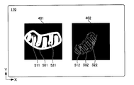
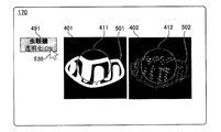
- FIG. 2 is a diagram showing a display screen of the display device 170.
- a first microscope image 401 and a second microscope image 402 at the time of acquisition are displayed on the image processing apparatus 101.
- the X axis and the Y axis are appropriately described in FIG. 2 and the subsequent drawings, these are for explaining the direction and do not mean a specific direction in the real space.
- the first microscope image 401 displayed on the left side in the figure includes a specimen image 501.
- the second microscope image 402 displayed on the right side in the drawing includes a specimen image 502 of the same specimen as the first microscope 710.
- the two specimen images 501 and 502 in both microscopic images have the magnification of the image (the size of the image).
- the orientation and position are different. That is, in the example of FIG. 2, the sample image 502 in the second microscope image 402 has a smaller dimension on the screen of the display device 170 than the sample image 501 in the first microscope image 401.
- the longitudinal direction of the specimen image 501 in the first microscope image 401 is substantially parallel to the X axis, whereas the specimen image 502 in the second microscope image 402 is inclined by about 45 ° from the X axis toward the Y axis. (Ie, leaning to the right). Furthermore, the specimen image 501 is located near the center of the first microscope image 401, while the specimen image 502 is located near the right end of the second microscope image 402.
- the first microscope image 401 and the second microscope image 402 are different in the size, inclination, and position of the specimen images 501 and 502 in each image. Therefore, even if the first microscope image 401 and the second microscope image 402 are displayed side by side on the display device 170, it is difficult for the user to compare and observe both images.
- FIG. 3 to 8 are diagrams for explaining the processing of the image corresponding unit 140.
- the image correspondence unit 140 performs processing for associating the first microscope image 401 and the second microscope image 402 as described below, for example.
- This associating process can be rephrased as a process of associating the pixel position, which is the two-dimensional coordinate position of the pixel constituting the first microscope image 401, with the pixel position, which is the two-dimensional coordinate position of the pixel constituting the second microscope image 402. it can.
- the associating process is performed.
- the process includes a process of specifying, in the second microscope image 402, a pixel having the same position on the microscope image as the pixel position in the first microscope image 401. Since the pixel position is a position in the first microscope image 401 and the second microscope image 402, it can also be called an image position.
- this associating process can be rephrased as a process of associating the first microscope image data 401 and the second microscope image data 402.
- the receiving unit 150 further receives from the user a designation of a position that is considered to correspond to a position designated in the first microscope image 401 in the second microscope image 402.
- the user designates in the second microscope image 402 a position that is considered to be the same part as the specimen part designated in the first microscope image 401.
- the image corresponding unit 140 displays the marker 512 at the designated position. In the example of FIG. 3, the position in the sample image 502 is designated.
- the user designates a position different from the marker 511 in the first microscope image 401 and the position designated in the first microscope image 401 in the second microscope image 402 (that is, a position different from the marker 511). ) (In other words, a position different from the marker 512) is input.
- the receiving unit 150 specifies the position in the first microscope image 401 and displays the marker 521, and specifies the position in the second microscope image 402 and displays the marker 522. indicate.
- the positions in the first microscope image 401 and the second microscope image 402 are designated, for example, when the user clicks the positions in the first microscope image 401 and the second microscope image 402 with a mouse, the positions are set.
- the location information to be specified is designated, and the reception unit 150 acquires the location information.
- 4 to 7 are diagrams illustrating the concept of processing executed by the image corresponding unit 140 after the position specified in FIG. 3 is specified.
- 4 to 8 show the first microscope image 401 and the second microscope image 402 as “images”, the image data processed inside the image processing apparatus 101 is shown for explanation. Thus, such an “image” is not generated or displayed on the display device 170.
- the image processing apparatus 101 handles the first microscope image 401 as data, hereinafter, it is also referred to as first microscope image data.
- the same reference number is used and the image is displayed. May be illustrated. The same applies to the second microscope image 402.
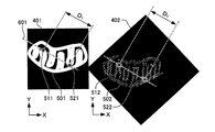
- FIG. 4 is a diagram for explaining processing of image data for aligning the orientation of the specimen image 501 in the first microscope image 401 and the specimen image 502 in the second microscope image 402.
- the image correspondence unit 140 generates data of a virtual straight line 601 that connects the markers 511 and 521 in the first microscope image 401.
- the image corresponding unit 140 generates data of a virtual straight line 602 that connects the markers 512 and 522 in the second microscope image 402.
- FIG. 5 is a diagram for explaining the next processing of FIG. 4 by the image corresponding unit 140.
- the image corresponding unit 140 displays the entire second microscope image 402 as shown by an arrow 611 in FIG.
- the second microscope image data 402 is processed so as to rotate from the state of FIG. 4 indicated by the dotted frame of 5 to the direction shown in FIG. 5 clockwise in FIG.
- the image correspondence unit 140 calculates a distance D 1 between the markers 511 and 521 of the first microscope image 401. Subsequently, the image corresponding unit 140 calculates a distance D 2 between the markers 512 and 522 of the second microscope image 402.
- FIG. 6 is a diagram for explaining the next processing of FIG. Since the relationship between the sizes of the distances D 2 and D 1 is D 2 ⁇ D 1 , when the sample image 502 (that is, the second microscope image 402) is multiplied by D 1 / D 2 , the sample image 501 as shown in FIG. That is, the size (magnification) coincides with (the first microscope image 401). Therefore, the image corresponding unit 140 processes the second microscope image data 402 so that the second microscope image 402 is multiplied by D 1 / D 2 .
- the image corresponding unit 140 displays the first microscope image 401 and the second microscope image in which the size, inclination, and position of the specimen image (that is, the first microscope image 401 and the second microscope image 402) are matched.
- the state displayed side by side on the screen of the apparatus 170 is shown.
- the image generation unit 160 matches the size, inclination, and position of the sample image 501 in the first microscope image 401 and the sample image 502 in the second microscope image 402 as illustrated in FIG. 7.
- the second microscope image 402 subjected to the image processing in this way only a portion having the same size as the first microscope image 401 is displayed on the display device 170.
- the specimen image 501 in the first microscope image 401 and the specimen image 502 in the second microscope image 402 have the same magnitude, inclination, and position. Therefore, the user can easily compare and observe the first microscope image 401 and the second microscope image 402.
- the image correspondence unit 140 processes the second microscope image data 402 so as to rotate, reduce, and further move the second microscope image 402, thereby obtaining the sample image 502 of the second microscope image 402.
- the size, orientation, and position of the sample were matched with the size, orientation, and position of the specimen image 501 of the first microscope image 401.
- the image corresponding unit 140 processes the first microscope image data 401 so as to rotate, enlarge, and move the first microscope image 401, and the size and direction of the specimen image 501 of the first microscope image 401.
- the position may be matched with the size, orientation, and position of the specimen image 502 of the second microscope image 402.
- FIG. 9 shows an image displayed on the display device 170 regarding the processing of the image generation unit 160.
- the specimen images of the first microscope image 401 and the second microscope image 402 are displayed in a state in which the sizes, orientations, and positions are aligned.
- designation of at least a part of position information in the first microscope image 401 is accepted.
- the image generation unit 160 displays a cursor 530 on the first microscope image 401 as shown in FIG. 9 by input from the user via the input device 130, for example, movement of the mouse. Furthermore, the reception unit 150 receives the position of a point designated by a user's mouse button pressing operation as position information (for example, the coordinates of the point). In FIG. 9, the user presses the mouse button at the position where the cursor 530 is displayed to specify a point. The position of the received point is displayed on the screen of the display device 170 by an X-shaped mark 531. Note that the accepting unit 150 may accept designation of a point by an operation such as depressing a return key, touching the display device 170 when the display device 170 is a touch panel, instead of depressing a mouse button.
- FIG. 10 is a diagram for explaining the processing of the image generation unit 160.
- the image generation unit 160 acquires position information (for example, point coordinates) of the point in the first microscope image 401 received by the reception unit 150 from the reception unit 150. Then, the image generation unit 160 specifies the first enlarged region 631 corresponding to the position of the point. More specifically, the image generation unit 160 expands a preset region including the point received by the reception unit 150 based on the position information of the point in the acquired first microscope image 401, that is, enlargement.
- the region 631 is specified.
- the first enlarged region 631 is a region surrounded by a circle with a preset radius 621 centered on the position of the mark 531.
- the receiving unit 150 may receive a designation using the position of the region in the first microscope image 401 as position information instead of the designation using the position of the point in the first microscope image 401 as the position information.
- a rectangle having a movement amount as a diagonal line is displayed by moving the mouse while dragging the mouse at a certain position, and the rectangle is displayed by the reception unit 150 by releasing the drag. May be accepted.
- the image generation unit 160 acquires information on the position of the designated rectangle (for example, the coordinates of the four vertices of the rectangle) from the reception unit 150, and is preset based on the information, including the designated rectangle.
- the specified area (for example, an area having a specified rectangular diagonal as a diameter) is specified as the first enlarged area 631.
- the receiving unit 150 may receive, as position information, coordinates of the first microscope image 401 (first microscope image data 401) that is directly input from the keyboard or the like as the input device 130.
- the coordinates of one point may be received so as to designate a point on the first microscope image 401, or the coordinates of a plurality of points (for example, a rectangular area) may be designated so as to designate an area on the first microscope image 401. If there are, the coordinates of four vertices) may be accepted.
- the image generation unit 160 acquires the received coordinates, and specifies the first enlarged region 631 including the points and regions corresponding to the coordinates. Further, the receiving unit 150 may receive a designation using the position of the first enlarged region 631 itself as position information. In this case, in the first microscope image 401, a circle having a movement amount as a diameter or a radius is displayed by moving the mouse while dragging at a certain position, and the circle is defined as a first enlarged region 631 by releasing the drag. It may be accepted. Then, the image generation unit 160 acquires information (for example, the center coordinates and radius of the circle) regarding the position of the designated circle (first enlarged region 631), and identifies the designated circle as the first enlarged region 631. . In any of the above cases, the designation of the region is not limited to a rectangle or a circle, and may be designated by another shape.
- the image generation unit 160 generates a first enlarged image 411 in which the first enlarged region 631 in the first microscope image 401 is enlarged.
- the enlargement magnification of the first enlarged image 411 may be a magnification set in advance in the image processing apparatus 101, or the image processing apparatus 101 may inquire the user after the position information is designated. It can be said that the first enlarged image 411 is an image displayed larger than the size when the first enlarged region 631 of the first microscope image 401 is displayed on the display device 170.
- the image generation unit 160 When generating the first enlarged image 411, if some of the pixels forming the image do not exist in the first microscope image 401 and the image is defective, the image generation unit 160 generates a complementary pixel.
- the missing pixels may be compensated. Since the first enlarged region 631 is at least a part of the first microscope image 401, it can be said that the first enlarged image 411 is an image obtained by enlarging at least a part of the first microscope image 401.
- FIG. 11 is a diagram for explaining the processing after FIG.
- the image generation unit 160 identifies a point in the second microscope image 402 corresponding to the point in the first microscope image 401 that has been designated by the reception unit 150. Specifically, the image generation unit 160 identifies the point of the position in the second microscope image 402 that is the same as the position of the point in the first microscope image 401 that has received the designation. In other words, the image generation unit 160 identifies in the second microscope image 402 a point having the same position on the microscope image as the position of the point in the first microscope image 401 that has received the designation. In other words, the image generation unit 160 identifies the pixel in the second microscope image 402 that is the same as the position of the pixel corresponding to the point in the first microscope image 401 that has received the designation.
- the image generation unit 160 specifies a circular region around the point specified in the second microscope image 402 and specifies the second enlarged region 632.
- the second enlarged region 632 has the same radius 622 as the first enlarged region 631.
- the image generation unit 160 enlarges the image of the second enlarged region 632 with respect to the second microscope image data 402 at the same magnification as the magnification of the first enlarged region 631, and generates the second enlarged image 412. .
- the second enlarged region 632 specified by the image generation unit 160 may not be set around the point (the point specified by the image generation unit 160) in the second microscope image 402, and the second enlarged image 412.
- the position where the second enlarged region 632 is set may be far from the center of the point (the point specified by the image generation unit 160) in the second microscope image 402 to the extent that there is no hindrance to the observation.
- the second enlarged image 412 is an enlarged image of a region including the point of the second microscopic image 402 corresponding to the point designated to be enlarged in the first microscopic image 401. 411.
- the second enlarged image 412 generated by the image generation unit 160 in relation to the first enlarged image 411 is not limited to the one corresponding to the position of each point, and may have some relationship. Good.
- the second enlarged region 632 is at least a part of the second microscope image 402, it can be said that the second enlarged image 412 is an image obtained by enlarging at least a part of the second microscope image 402.
- FIG. 12 is an example in which the first enlarged image 411 and the second enlarged image 412 are displayed on the display device 170.
- the image generation unit 160 superimposes the first enlarged image 411 on the first microscope image 401 and displays it on the display device 170.
- the center of the first enlarged image 411 coincides with the position of the point that is designated by the accepting unit 150 in the first microscope image 401. Therefore, the first enlarged image 411 displays the area around the point where the designation of the first microscope image 401 is accepted as if it is being magnified and observed with a magnifying glass. Since the entire image can be observed, an enlarged image can be observed with respect to the region that the user has focused on (that is, the region including the position specified in the first microscope image 401), so that the microscope image can be observed intuitively. Work can be carried out.
- the image generation unit 160 displays the second enlarged image 412 superimposed on the second microscope image 402.
- the center of the second enlarged image 412 coincides with the position of the point specified by the image generation unit 160 in the second microscope image 402. Therefore, the second magnified image 412 displays the area around the point specified in the second microscope image 402 as if it were magnified and observed with a magnifying glass, so that the user can view the entire second microscope image 402. Intuitive observation of a microscope image can be performed while looking down.
- the first microscopic image 401 (specimen image) and the second microscopic image 402 (specimen image) are displayed in advance with the size (magnification), orientation, and position matched.
- the first enlarged image 411 and the second enlarged image 412 are enlarged at the same magnification with respect to the displayed first microscope image 401 and second microscope image 402, respectively.
- the images of the first microscope image 401 and the second microscope image 402 are captured.
- the entire comparative observation can be easily performed. Furthermore, it is possible to easily carry out comparative observation on the region noted by the user in the first microscope image 401 and the second microscope image 402.
- the user designates the position of the point to be enlarged in the first microscope image 401, not only the first enlarged image 411 of the area including the position but also the second enlarged image 412 of the area including the corresponding point is displayed.
- the device 170 is displayed. Therefore, the first magnified image 411 and the second magnified image 412 can be easily compared and observed without the trouble of specifying the position of the point to be magnified in each of the first microscope image 401 and the second microscope image 402.
- the image generation unit 160 extracts a part of the second microscope image 402 that overlaps the first enlarged image 411.
- the first enlarged image 411 may be displayed hidden.
- the image generation unit 160 extracts a part of the first microscope image 401 that overlaps the second enlarged image 412.
- the second enlarged image 412 may be displayed hidden.
- the image generation unit 160 may fill a plain image.
- FIG. 13 is a flowchart showing a processing procedure in the image processing apparatus 101.
- the image processing apparatus 101 acquires a first microscope image 401 (first microscope image data) and a second microscope image 402 (second microscope image data) from the microscope 700 (S101).
- the image corresponding unit 140 uses the method illustrated in FIGS. 3 to 7 to perform the first microscope image 401 and the second microscope image 402 on the first microscope image 401 and the second microscope image 402.
- the association is executed (S102).
- the image association unit 140 matches the size, orientation, and position of the specimen images of the first microscope image 401 and the second microscope image 402 and displays them on the display device 170 as shown in FIG. S103).
- the image generation unit 160 specifies the second enlarged region 632 of the second microscope image 402 (S106).
- the first microscope image 401 and the second microscope image 402 have the same size, orientation, and position of the specimen image, as described with reference to FIG. 11, the first microscope input in step S104.
- the position of the point in the second microscope image 402 that is the same as the position of the point in the image 401 is specified as the position of the center of the second enlarged region 632.
- the image generation unit 160 generates a second enlarged image 412 in which the second enlarged region 632 in the second microscope image 402 is enlarged (S107).
- the image generation unit 160 displays the first microscope image 401 and the second microscope image 402, the first enlarged image 411, and the second enlarged image 412 side by side on the display device 170. (S108).
- a communication unit that can acquire a microscope image from the outside of the microscope system 100 may be provided in the image processing apparatus 101.
- the communication unit may acquire the first microscope image 401 or the second microscope image 402 from an external database or the like through the Internet, a dedicated line, etc., and use it for the image processing apparatus 101.
- step S102 of FIG. 13 instead of accepting designation of a position used for associating the first microscope image 401 and the second microscope image 402 from the user, they are included in the first microscope image 401 and the second microscope image 402.
- the image corresponding unit 140 may automatically extract a plurality of marker images and use the positions.
- a marker is introduced around the specimen or the specimen.
- existing markers such as gold fine particles and fluorescent labels can be used.
- the image correspondence unit 140 is a method similar to the method described with reference to FIGS. 3 to 7, and the positions of the plurality of marker images in the first microscope image 401 (position coordinates in the first microscope image 401). And the rotation amount, size ratio, and movement amount of the second microscope image 402 such that the positions of the plurality of marker images in the second microscope image 402 coincide with each other (position coordinates in the second microscope image 402). calculate.
- step S102 the user automatically designates the first microscope image 401 and the first microscope image 401 without specifying the position for association with the first microscope image 401 and the second microscope image 402. Since the two microscope images 402 can be associated with each other, the labor of comparative observation between the first microscope image 401 and the second microscope image 402 is reduced.
- the position of the marker introduced around the specimen and the specimen does not change when the first microscope image 401 and the second microscope image 402 are imaged, by using the marker image for association, Accurate association can be performed.
- the user may specify a plurality of markers in the first microscope image 401 and a plurality of markers in the second microscope image 402.
- the image association unit 140 may associate the microscope images with each other using morphological features appearing in both the first microscope image 401 and the second microscope image 402. For example, cell surface protrusion structures, intracellular mitochondrial shapes, cover glass scratches, and the like may be used as markers.
- the image correspondence unit 140 may automatically extract the images of these markers and execute the association between the microscopic images.
- the image correspondence unit 140 accepts designation of the positions of these marker images by the user. The association between the microscope images may be executed.
- FIG. 14 is a diagram for explaining another example of step S102 in FIG.
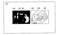
- a first microscope image 401 is an image obtained by SIM
- a second microscope image 402 is an image obtained by an electron microscope.
- sample images 451 and 452 appear as they are in the microscope image of the SIM and the microscope image of the electron microscope. Therefore, in step S102 of FIG. 13, the image correspondence unit 140 performs pattern matching between the first microscope image 401 by the SIM and the second microscope image 402 by the electron microscope, thereby obtaining the first microscope image 401 and the second microscope image 402. Associate.
- the image corresponding unit 140 instead of accepting designation of a plurality of positions in both microscope images from the user in step S102 of FIG. 13, uses the pattern of the first microscope image 401 and the second microscope image 402. Perform matching. In this case, the image corresponding unit 140 calculates the rotation amount, magnification, and position displacement amount of the second microscope image 402 with respect to the first microscope image 401, in which the similarity between the microscope images is the highest. Then, as shown in FIG. 8, the image corresponding unit 140 performs image processing on the second microscope image 402 (second microscope image data) based on these calculated values, and the first microscope image 401 and the second microscope image. 402 is associated.
- the microscope images can be easily associated with each other by pattern matching, and the labor for comparative observation between the microscope images is reduced.
- pattern matching a known method such as a normalized correlation method or a geometric shape pattern matching method is used. Pattern matching is paraphrased as template matching.
- compatible part 140 does not need to perform pattern matching using the whole image in each microscope image.
- the accepting unit 150 accepts designation from the user as an area for performing pattern matching for a partial area of the first microscope image 401, and the image correspondence unit 140 uses the second area and the second area in the designated first microscope image 401.
- the microscope image 402 may be pattern-matched, and the accepting unit 150 accepts designation of a part of the second microscope image 402 from the user, and the image corresponding unit 140 accepts the designated first microscope image.
- the region in 401 and the designated region in the second microscope image 402 may be pattern-matched.
- a foreign object such as dust
- texture such as a stain
- FIG. 15 is a diagram for explaining a modification of the pattern matching in FIG.
- the image corresponding unit 140 performs pattern matching between the first enlarged image 461 and the second microscope image 402 instead of the pattern matching between the first microscope image 401 and the second microscope image 402 described in FIG. Do.
- the image corresponding unit 140 receives an input of a position to be enlarged for pattern matching from the user via the input device 130 in step S102 of FIG.
- the image corresponding unit 140 performs pattern matching using a pattern included in the first enlarged image 461 at the position as shown in FIG.
- the pattern matching method is the same as described in FIG.
- the range of the first enlarged image 461 is narrower than that of the first microscope image 401.
- the possibility that dust or the like is included in the first enlarged image 461 is reduced, and the possibility of erroneous detection of pattern matching can be reduced.
- the pattern included in the first enlarged image 461 is searched for the second microscope image 402.
- the specification of the position to be enlarged in the second microscope image 402 may be received, and the pattern included in the enlarged image obtained by enlarging the area including the position may be pattern-matched with the first microscope image 401.
- the image association unit 140 sets the microscope 700 when the first microscope image 401 is captured and the setting of the microscope 700 when the second microscope image 402 is captured.
- Conditions may be acquired, and the first microscope image 401 and the second microscope image 402 may be associated with each other based on the conditions.
- the setting conditions include the imaging magnification of the microscope, stage coordinates, and the like.
- the image correspondence unit 140 may associate the microscope images using both the imaging magnification and the stage coordinates, or may associate using either one.
- the imaging magnification is a magnification at which an image of a specimen is imaged on an imaging surface of an imaging device (CCD, CMOS, etc.) of the microscope when the specimen on the stage is imaged with each microscope.
- the image correspondence unit 140 determines the magnification of the sample image 501 in the first microscope image 401 and the first microscope from the imaging magnification when the first microscope image 401 is captured and the imaging magnification when the second microscope image 402 is captured.
- the magnification of the sample image 502 in the image 401 can be associated. Thereby, for example, the size of the sample image 501 in the first microscope image 401 when displayed on the display device 170 and the size of the sample image 502 in the second microscope image 402 can be matched. Therefore, both comparative observations become easy.
- the stage coordinates are the coordinates of the stage on which the specimen is placed, which is acquired when the specimen is imaged with each microscope.
- the image correspondence unit 140 determines the position of the sample image 501 in the first microscope image 401 and the second microscope image 402 from the stage coordinates when the first microscope image 401 is captured and the stage coordinates when the second microscope image 402 is captured. Can be associated with the position of the sample image 502. Thereby, for example, the position of the specimen image 501 in the first microscope image 401 when displayed on the display device 170 and the position of the specimen image 502 in the second microscope image 402 can be matched. Therefore, both comparative observations become easy.
- step S103 of FIG. 13 the size, orientation, and position of the image are displayed based on the correspondence between the first microscope image 401 and the second microscope image 402.
- the second microscope image 402 may be omitted from displaying the image in the same size, orientation, and position.
- step S102 the method of associating the microscope images described with reference to FIGS. 3 to 7, the method of associating the microscope images described with reference to FIGS. 14 and 15, and the above-described imaging of the microscope images.
- the image generation unit 160 determines the size of each image specified in the association between the first microscope image 401 and the second microscope image 402. Based on the orientation and position, the second enlarged area is identified in step S106 in correspondence with the identification of the first enlarged area in step S105.
- FIG. 16 is a block diagram of a microscope system 105 using another microscope image
- FIG. 17 is a diagram illustrating a microscope image used in the microscope system 105.
- the microscope system 105 is different from the microscope system 100 in that the microscope 700 is a single unit.
- the same components as those in the microscope system 100 are denoted by the same reference numerals, and description thereof is omitted.
- the image association unit 140 acquires a group of microscope images captured at a plurality of focal planes from a single microscope 700.
- the image corresponding unit 140 generates stereoscopic microscope image data (stereoscopic microscope image) having three-dimensional luminance distribution information by synthesizing the microscope images (luminance distribution) of the microscope image group.
- the accepting unit 150 designates two plane microscope image data (planar microscope images) to be cut out from the stereoscopic microscope image data (stereoscopic microscope image) as planes parallel to each other as the first microscope image 401 and the second microscope image 402. Accept.
- the reception unit 150 receives the designation of the first microscope image 401 and the second microscope image 402 with the mouse by the user.
- the image correspondence unit 140 further associates the first microscope image 401 and the second microscope image 402 in step S102 of FIG.
- the image correspondence unit 140 performs the method of associating the microscope images described with reference to FIGS. 3 to 7, the method of associating the microscopes described with reference to FIGS. Any method of performing association using the setting information of the microscope may be used. Thereby, for example, even when the specimen moves with a time difference that occurs when different focal planes are imaged, it is possible to appropriately associate them. Therefore, even if the planar microscope images are cut out on different planes, the size, orientation, and position of the specimens of both microscope images are aligned, so that they can be comparatively observed easily.
- step S103 in FIG. 13 the operations after step S103 in FIG. 13 are performed. Specifically, the image corresponding unit 140 displays the first microscope image 401 and the second microscope image 402 on the display device 170 (S103 in FIG. 13).
- the image generation unit 160 specifies the first enlarged region 631 of the first microscope image 401 (S105 in FIG. 13). ), A first enlarged image 411 in which the first enlarged region 631 in the first microscope image 401 is enlarged is generated (S109 in FIG. 13).
- the image generation unit 160 identifies the second enlarged region 632 of the second microscope image 402 (S106 in FIG. 3), and expands the second enlarged region 432 of the second microscope image 402 as a second enlarged image 412. Generate (S107 in FIG. 13). Further, as described with reference to FIG. 12, the image generation unit 160 displays the first microscope image 401 and the second microscope image 402, the first enlarged image 411, and the second enlarged image 412 side by side on the display device 170. (S108 in FIG. 13).
- stereo microscope image data was generated from a group of microscope images acquired from a single microscope 700.
- stereo microscope image data may be generated by acquiring microscope images from a plurality of microscopes and synthesizing the plurality of microscope images.
- the direction of each plane from which the stereoscopic microscope image is cut out may be freely specified by the user via the input device 130.
- the first microscope image 401 and the second microscope image 402 planes parallel to each other in an arbitrary direction may be cut out from the stereoscopic microscope image data (stereoscopic microscope image). If there is no hindrance to the comparative observation, the first microscope image 401 and the second microscope image 402 may be cut out of planes that are not parallel to each other in the stereoscopic microscope image data (stereoscopic microscope image).
- the same objective lens is often used for detection of fluorescence intensity at each focal plane.
- the image correspondence unit 140 may omit the process of matching the size of the image.
- the first microscope image 401 and the second microscope image 402 may have the same orientation, size, and position. In this case, the association between the first microscope image 401 and the second microscope image 402 shown in FIGS. 3 to 7 in step S102 of FIG. 13 may be omitted.
- FIG. 18 is a diagram illustrating another combination of microscope images used in the microscope system 105 of FIG.
- the microscope image group 450 in FIG. 18 includes a plurality of microscope images obtained by photographing the observation region (imaging field of view of the microscope) at arbitrary elapsed times (so-called image group acquired by time-lapse photography).
- the image association unit 140 acquires a group of microscope images that have been time-lapse shot with a single microscope 700.
- the image groups in the time ranges different from each other in the microscope image group 450 are displayed in two columns.
- the image corresponding unit 140 receives the designation of the first microscope image 401 and the second microscope image 402 acquired from different time ranges in the microscope image group 450 via the input device 130 in step S102 of FIG. In other words, in this example, as the first microscope image 401 and the second microscope image 402, microscope images with different times taken are designated.
- the image correspondence unit 140 further associates the first microscope image 401 and the second microscope image 402 with the method described with reference to FIGS. As a result, even when the sample moves with the time difference of imaging, it is possible to appropriately associate.
- the image corresponding unit 140 displays the first microscope image 401 and the second microscope image 402 on the display device 170 in step S103 of FIG.
- the accepting unit 150 accepts designation of position information to be enlarged in the first microscope image 401 via the input device 130 in step S104 of FIG.
- step S105 in FIG. 13 the operations after step S105 in FIG. 13 are performed. Specifically, when position information is input from the user via the input device 130, the image generation unit 160 specifies the first enlarged region 631 of the first microscope image 401 (S105 in FIG. 13), and A first enlarged image 411 in which the first enlarged region 631 in the one microscope image 401 is enlarged is generated (S109 in FIG. 13).
- the image generation unit 160 will be described with reference to FIGS. 10 and 11 based on the size, direction, and position of each image specified in the association between the first microscope image 401 and the second microscope image 402. As described above, the position of the point of the second microscope image 402 corresponding to the position of the point of the first microscope image 401 designated by the user is specified (S106 in FIG. 3). Furthermore, the image generation unit 160 generates a second enlarged image 412 in which a region including the identified point of the second microscope image 402 is enlarged (S107 in FIG. 3).
- the image generation unit 160 displays the first microscope image 401 and the second microscope image 402, the first enlarged image 411, and the second enlarged image 412 side by side on the display device 170. (S108 in FIG. 13).
- the image generation unit 160 superimposes the first enlarged image 411 on the first microscope image 401 and also superimposes the second enlarged image 412 on the second microscope image 402 and displays it on the display device 170 (S108 in FIG. 13).
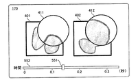
- the first enlarged image 411 and the first enlarged image 411 which are partial enlarged images of the first microscope image 401 and the second microscope image 402, which are selected from the microscope image group 450 generated by time-lapse photography and have different times of imaging, are used.
- Two enlarged images 412 can be displayed on the display device 170 for comparative observation. Therefore, comparative observation of time-lapse images can be easily performed.
- the image generation unit 160 displays the first microscope image 401 and the second microscope image 402 on the display device 170 over time.
- the first enlarged image 411 is switched corresponding to the first microscope image 401 displayed sequentially.
- the second enlarged image 412 is also switched along with the second microscope image 402 that is sequentially displayed. This makes it possible to efficiently compare and observe temporal changes in phenomena occurring in the specimen.
- the image generation unit 160 accepts switching of the first enlarged image 411 and the second enlarged image 412 displayed on the display device 170 from the user by operating the slider 551. Specifically, the image generation unit 160 determines the length of time-lapse shooting time represented by the image groups arranged in two rows in FIG. 18 (if the time lengths indicated by the two rows of image groups are the same, the time If one of the time lengths is different, the length of the bar 552 is displayed on the display device 170 as shown in FIG. The bar 552 indicates a range in which the user can move the slider 551. When the operation of the slider 551 is received via the input device 130, the image generation unit 160 specifies the time corresponding to the position from the position on the bar 552 of the slider 551.
- the image generation unit 160 specifies the first microscope image 401 and the second microscope image 402 corresponding to the specified time from the respective image groups, and the first enlarged image 411 and the second microscope image of the specified first microscope image 401. Displayed together with the second enlarged image 412 of 402. Thereby, the user can observe the respective temporal changes of the first enlarged image 411 and the second enlarged image 412 by operating the slider 551, and can further improve the efficiency of comparative observation.
- a microscope image that was time-lapse photographed with a single microscope was used, but instead, a microscope image was obtained from each of a plurality of microscopes, and the plurality of microscope images were photographed. It is good also as the microscope image imaged by the time lapse by arranging in order.
- the first microscope image 401 and the second microscope image 402 are acquired from an image obtained by observing one specimen in time order.
- the first microscopic image 401 and the second microscopic image 402 may not be included in the group of microscopic images taken in a series of time passages.
- the first microscopic image 401 is selected from a group of microscopic images obtained by applying reagent A to the sample and taking an image with time, and then applying reagent B to the sample and taking an image with time.
- the second microscope image 402 may be selected from the microscope image group.
- the same reagent is given to different specimens, and the first microscopic image 401 and the second microscopic image 402 are selected from the respective microscopic image groups obtained by imaging the respective specimens over time. Also good.
- the slider 551 in FIG. 19 specifies the first microscope image 401 and the second microscope image 402 from among images obtained by cutting out a plurality of planes in the stereoscopic microscope image data, as described with reference to FIG.
- the image generation unit 160 displays these microscopic images on the display device 170.
- the receiving unit 150 stores the position of the slider 551 in association with the position of the plane from which the stereoscopic microscope image data is cut out.
- the receiving unit 150 specifies the position of the plane from which the stereoscopic microscope image data is cut out from the received position of the slider 551, and the image generating unit 160.
- the image generation unit 160 displays a planar microscope image on the plane on the display device 170.
- FIG. 20 is a diagram for explaining another example using a time-lapse image.
- the time-lapse image described with reference to FIGS. 18 and 19 there are cases where the position or region of interest of the user moves. Therefore, in this example, it is detected to which position in the first microscopic image 401 and the second microscopic image 402 that the position that has been designated to be enlarged in the first microscopic image 401 has moved after that. .
- the pattern matching described with reference to FIGS. 14 and 15 can be used.
- the image corresponding unit 140 acquires a group of microscope images that are time-lapse shot with a single microscope 700.
- the image corresponding unit 140 receives designation of the first microscope image 401 and the second microscope image 402 acquired from different time ranges in the above-described microscope image group via the input device 130.
- the image processing apparatus 101 operates as follows instead of steps S102 to S107 in FIG.
- the receiving unit 150 receives from the input device 130 the designation of the position of the first microscope image 401 that the user wants to pay attention to, and the image handling unit 140 identifies the region 453 that includes the position.
- the image correspondence unit 140 uses the region 453, the image correspondence unit 140 performs pattern matching with a plurality of first microscope images 401 at times later than the currently displayed first microscope image 401.
- the image corresponding unit 140 enlarges each of the regions detected as having high similarity to the region 453 in the plurality of first microscope images 401 at a time later than the first microscope image 401, thereby One enlarged image 411 is generated.
- the image corresponding unit 140 further uses the region 453 to perform pattern matching with the currently displayed second microscope image 402 and a plurality of second microscope images 402 at the subsequent times, and the first microscope image 401 and the second microscope The image 402 is associated. Thereby, the image corresponding unit 140 enlarges each of the regions 454 detected as having a high similarity to the region 453 in the plurality of second microscope images 402, and generates a plurality of second enlarged images 412.
- the image generation unit 160 displays the first enlarged image 411 and the second enlarged image on the display device 170 over time. Thereby, even if the position and area which a user pays attention to have moved in the time lapse image, enlarged images obtained by enlarging the position and area can be easily compared.
- the first microscope image 401 and the first enlarged image 411 are not changed, and only the second microscope image 402 and the second enlarged image 412 are changed over time. It may be displayed.
- FIG. 21 is a block diagram of a microscope system 100 including another image processing apparatus 102.
- the image processing apparatus 102 has the same structure as the image processing apparatus 101 shown in FIG. Elements common to the image processing apparatus 101 are denoted by the same reference numerals, and redundant description is omitted.
- the image processing apparatus 102 is different from the image processing apparatus 101 in that in addition to the reception unit 150 that receives the position specified by the input device 130, the image processing apparatus 102 includes a processing reception unit 151 that similarly receives a display condition input from the input device 130.
- the display condition is a condition for changing the display on the display device 170 by processing the first enlarged image 411 once generated.
- the display conditions include a range enlarged by the first enlarged image 411, an image magnification, an image brightness, an image contrast, an image rotation, and an image inversion.
- FIG. 22 is a diagram illustrating a case where a range to be enlarged by the first enlarged image 411 is designated as the display condition.
- the user drags the outline of the first enlarged image 411 with the cursor 530 on the first enlarged image 411 displayed on the display device 170 to specify the changed size.
- the user can instruct the enlargement of the display area of the first enlarged image 411 by dragging the cursor 530 toward the outside in the radial direction of the first enlarged image 411.
- the user determines the size of the first enlarged image 411 after image processing by releasing the drag at a desired position.
- FIG. 23 is a diagram for explaining processing subsequent to FIG.
- the image generating unit 160 converts the initial first enlarged image 411 to the range of the first enlarged image 421 corresponding to the enlarged display range. Expanding. Accordingly, the image processing apparatus 102 enlarges the initial second enlarged image 412 to the same size as the enlarged first enlarged image 421, and generates an enlarged second enlarged image 422.
- the first microscope image 401 and the second microscope image 402 have the same size, orientation, and position, the first microscope image 401 (specimen image) and the second microscope image 402 (specimen image).
- the enlargement process is performed at the same position, the same magnification, and the same range. Thereby, the enlarged first enlarged image 421 and the enlarged second enlarged image 422 are juxtaposed.
- FIG. 24 is a flowchart showing a process execution procedure in the image processing apparatus 102.
- steps S101 to S108 are the same as FIG.
- the process accepting unit 151 inputs display conditions in this state.
- the presence or absence of is accepted (S121).
- the image generating unit 160 executes image processing under the display condition on the first enlarged image 411 (S122). In addition, the image generation unit 160 causes the image processing executed on the first enlarged image 411 to be reflected and executed on the second enlarged image 412 generated corresponding to the first enlarged image 411 (S123). ).
- the image generation unit 160 generates a first enlarged image 421 and a second enlarged image 422 after image processing (S124), and displays them on the display device 170 (S125). Thereby, the process performed when the process reception part 151 receives display conditions is completed.
- the image processing apparatus 102 can further perform image processing on the first enlarged image 411 and the second enlarged image 412 according to the input display conditions after the processing by the image generation unit 160 is once completed. Thereby, it is possible to make the first enlarged image 411 and the second enlarged image 412 after processing displayed on the display device 170 easier to see and further improve the efficiency of comparative observation.
- the image processing apparatus 102 also performs image processing equivalent to the first enlarged image 411 for the second enlarged image 412 when the display condition for the first enlarged image 411 is input. Thereby, since the trouble of designating the display conditions of the first enlarged image 411 and the second enlarged image 412 can be saved, both can be compared and observed efficiently.
- the designation method when the display condition is designated in step S121 is not limited to the method of operating the movement of the cursor on the first enlarged image 411.
- a menu listing the types of image processing and the parameter values as options may be displayed, and the contents designated by the menu may be selected.
- the actual size of the sample may be specified by a numerical value, or specified by the number of pixels on the display device 170, the magnification with respect to the size of the original area, or the like. May be.
- a plurality of first enlarged images 411 having different sizes may be displayed and selected from them.
- the process accepting unit 151 may accept a display condition other than the range enlarged in the first enlarged image 411 described in FIG. 23 as the display condition.
- the image generation unit 160 rotates the first enlarged image 411 and superimposes it on the first microscope image 401.
- the image generation unit 160 also rotates the second enlarged image 412 and superimposes it on the second microscope image 402.
- the image generation unit 160 makes the second enlarged image 412 the same angle as the first enlarged image 411. Rotate.
- the process accepting unit 151 may accept image magnification, image brightness, image contrast, and image inversion as further display conditions. Regardless of which display condition is accepted, the image generation unit 160 generates a first enlarged image 411 and a second enlarged image 412 after image processing according to the display condition, and the first microscope image 401 and the second microscope image 402. Are displayed on the display device 170 in a superimposed manner. Thereby, since the trouble of designating each of the processing of the first enlarged image 411 and the second enlarged image 412 can be saved, both can be compared and observed efficiently.
- the receiving unit 150 may receive an instruction to move the first enlarged image 411.
- the reception unit 150 receives the movement, and the direction and amount of movement are received by the image generation unit.
- the image generation unit 160 moves the first enlarged region 631 in the first microscope image 401 by the movement direction and the movement amount received by the receiving unit 150, and enlarges the first enlarged region 631 after the movement. 411 is generated. Further, the image generation unit 160 moves the second enlarged region 632 in the second microscope image 402 by the movement direction and the movement amount received by the receiving unit 150, and expands the second enlarged region 632 after the movement.
- the process accepting unit 151 may accept a change in the position where the first enlarged image 411 is displayed.
- the process accepting unit 151 accepts the movement and generates an image of the moving direction and the moving amount.
- the image generation unit 160 displays the first enlarged image 411 at the moved position with the movement direction and movement amount received by the processing reception unit 151, and the second enlarged image 412 also moves at the same movement direction and movement amount. To display. Thereby, on the display device 170, the second enlarged image 412 is also moved and displayed in synchronization with the movement of the first enlarged image 411.
- the second enlarged image 412 also moves together in response to an instruction to move the first enlarged image 411, the user moves the first enlarged image 411 and the second enlarged image 412 to a place where the user can easily see them, and easily compares and observes both. can do.
- FIG. 25 and FIG. 26 are diagrams for describing processing for accepting scanning on the first microscope image 401 and the second microscope image 402 instead of accepting the display condition in step S121 of FIG.
- the user when comparatively observing the first enlarged image 411 and the second enlarged image 412, the user can instruct the processing reception unit 151 in the scanning mode.
- the scanning mode the position at which scanning starts, the direction of scanning, and the position at which scanning ends are set by default, but may be specified by the user via the input device 130.
- the image generation unit 160 scans the first microscope image 401 along the scanning direction from the start point of the first microscope image 401, and sequentially generates and displays the first enlarged image 411 including the scanning position.
- FIG. 25 shows the first enlarged image 411 and the second enlarged image at the starting point
- FIG. 26 shows the first enlarged image 411 and the second enlarged image in the middle of the scanning.
- the image generation unit 160 sequentially generates and displays second enlarged images 412 at corresponding positions of the second microscope image 402 in synchronization with the scanning of the first microscope image 401.
- the scanning mode described with reference to FIGS. 25 and 26 can also be used for comparative observation of a plurality of well samples arranged two-dimensionally on a well plate. For a plurality of wells, the amount, concentration, type, and time elapsed since administration of the drug are different from each other.
- the image corresponding unit 140 captures a first microscope image 401 obtained by imaging a specimen of a specific well and a plurality of specimens obtained by imaging a plurality of well samples different from the specific well.
- the second microscopic image 402 is acquired.
- the reception unit 150 receives designation of the position of the point to be enlarged in the first microscope image 401, and the image generation unit 160 generates a first enlarged image 411 in which the region including the point in the first microscope image 401 is enlarged.
- the receiving unit 150 may receive designation of the position of the area of the first microscope image 401 instead of designation of the position of the point of the first microscope image 401.
- the image generation unit 160 specifies a point in each of the plurality of second microscope images 402 corresponding to the point in the first microscope image 401 for which the designation is received by the reception unit 150. Specifically, the image generation unit 160 has the same position (second microscope) as the point position (position coordinates in the first microscope image 401) in the first microscope image 401 that has received the designation. A point of position coordinates in the image 402 is specified. The image generation unit 160 further generates a plurality of second enlarged images 412 obtained by enlarging a region including the point of the plurality of second microscope images 402, and displays the plurality of second enlarged images 412 together with the first enlarged image 411. The information is sequentially displayed on the device 170.
- each of the first microscope image 401 and each of the plurality of second microscope images 402 may be specified using the pattern matching described with reference to FIGS. 14 and 15.
- the image generation unit 160 starts scanning based on the input from the user or the default setting, as described with reference to FIGS. 25 and 26.
- the direction of scanning and the position at which scanning ends are specified, and the second enlarged image 412 of the well corresponding to the position on the scanning is sequentially displayed.
- FIG. 27 is a block diagram of another image processing apparatus 103.
- the image processing apparatus 103 has the same configuration as the image processing apparatus 101 shown in FIG. Therefore, the same reference numerals are assigned to the common configurations, and duplicate descriptions are omitted.
- the image processing apparatus 103 further includes a transparency receiving unit 152 and an overlay receiving unit 153 that receive an instruction from the input device 130.
- the transparency accepting unit 152 accepts a transparency instruction from the user input through the input device 130.
- the overlay receiving unit 153 receives an image overlay instruction from the user input through the input device 130.
- FIG. 28 is a diagram for explaining the processing of the image processing apparatus 103.
- the image corresponding unit 140 displays the image on the display device 170 before the transparency instruction is input.
- a first enlarged image 411 and a second enlarged image 412 are displayed so as to overlap the first microscope image 401 and the second microscope image 402, respectively.
- a button 491 that supports transparency is further displayed.
- the image generation unit 160 that has acquired the instruction through the transparency reception unit 152 uses the cursor 530 operated by a pointing device such as a mouse to perform the first enlarged image 411 and the second enlarged image. Which of the images 412 is to be made transparent is selected. In the illustrated example, the first enlarged image 411 is selected and made transparent.
- transparency means translucency so that the content of the 1st expansion image 411 can be understood and the foundation
- the image processing apparatus 103 displays a slider 551 for adjusting the transmittance on the display device 170 so that the user can set the transmittance.
- the overlay receiving unit 153 receives an instruction when the user inputs an instruction for overlapping through the input device 130.
- the image generation unit 160 executes an overlay process for generating a superimposed image 414 in which the first enlarged image 411 and the second enlarged image 412 are overlaid. .
- the overlay receiving unit 153 moves the first enlarged image 411 by dragging the cursor 530 on the first enlarged image 411 and superimposes it on the second enlarged image 412. Judge that there was. Instead of moving the first enlarged image 411 by dragging, a superimposing instruction may be received by a button, a menu item, or the like. When a superimposition instruction is received by a button, menu item, or the like, the superposition image may be displayed at one of the first enlarged image 411 and the second enlarged image 412, or the first enlarged image 411 and The superimposed image may be displayed at a position different from any position of the second enlarged image 412.
- FIG. 29 shows a state in which the superimposed image 414 is displayed.
- the image generation unit 160 uses the first enlarged image 411 that has been previously transparentized as an upper layer in the region where the first enlarged image 411 and the second enlarged image 412 overlap each other, and the second enlarged image that has not been made transparent.
- the superimposing process with 412 as the background is executed. Thereby, it becomes easy to grasp the difference between the first enlarged image 411 and the second enlarged image 412. Therefore, the efficiency of comparative observation between the first microscope image 401 and the second microscope image 402 is improved.
- the image generation unit 160 may be configured to replace the enlarged image to be transparent and the enlarged image to be used as a background according to a user instruction.
- one of the first enlarged image 411 and the second enlarged image 412 may be subjected to image processing so as to have a color, brightness, or the like different from the other image.
- image processing is performed so that one image of the first enlarged image 411 and the second enlarged image 412 has a different color from the other image
- one image of the first enlarged image 411 and the second enlarged image 412 is changed to the other image.
- Image processing may be performed so that the color tone is different from that of the first image. This makes it easier to compare the first enlarged image 411 and the second enlarged image.
- FIG. 30 is a flowchart showing the operation procedure of the image processing apparatus 103.
- steps S101 to S108 are the same as those in FIG.
- the transparency receiving unit 152 makes the transparency in this state. Is received (S131).
- the image generating unit 160 performs transparency on the first enlarged image 411, for example (S132).
- the overlay receiving unit 153 waits while monitoring the presence / absence of an overlay instruction (S133: NO).
- the image generating unit 160 When the overlay receiving unit 153 receives an overlay instruction (S133: YES), the image generating unit 160 generates the superimposed image 414 by superimposing the first enlarged image 411 and the second enlarged image 412 (S134). . The image generation unit 160 causes the display device 170 to display the superimposed image 414 generated on the second microscope image 402 (S135). Thus, the image processing by the image processing apparatus 103 is completed.
- FIG. 31 is a diagram for explaining still another operation of the image processing apparatus 101.
- a first microscope image 401, a second microscope image 402, a first enlarged image 411, and a second enlarged image 412 are displayed as in FIG.
- steps S105 to S108 in FIG. 13 are repeated, and the first magnified image 411 and the second magnified image corresponding to the position are displayed on the display device 170.
- An image 412 is displayed.
- the user sequentially observes the first enlarged image 411 and the second enlarged image 412, but then wants to observe the first enlarged image 411 and the second enlarged image 412 at a specific position that has been compared and observed before.
- the image generating unit 160 displays the first enlarged image 411 and the second enlarged image 412 on the display device. 170, and a marker 475 is displayed at each position of the first microscope image 401.
- the first enlarged image 411 and the second enlarged image 412 are stored in the image processing apparatus 101 in association with the respective positions.
- the image generation unit 160 displays the first enlarged image 411 and the second enlarged image 412 stored for the position corresponding to the marker 475 on the display device 170. To do. Note that the image generation unit 160 may automatically display the first enlarged image 411 and the second enlarged image 412 sequentially for the plurality of markers 475 based on an instruction from the user.
- the marker 475 may be displayed at a point corresponding to the point designated by the user in the first microscope image 401 in the second microscope image 402, or on both the first microscope image 401 and the second microscope image 402. May be displayed.
- the image generation unit 160 may display the first enlarged image 411 separately on the display device 170 without being superimposed on the first microscope image 401, or the second enlarged image.
- the image 412 may be displayed separately on the display device 170 without being superimposed on the second microscope image 402.
- the image generation unit 160 also places the first enlarged image at a position different from the position designated to be enlarged in the first microscope image 401. 411 may be superimposed.
- the image generation unit 160 performs the second enlargement at a position different from the designated position in the second microscope image 402.
- the image 412 may be superimposed.
- first microscope image 401 and the second microscope image 402 obtained by the SIM, the STORM, and the electron microscope images obtained by other microscope methods are used as the first microscope image 401 and the second microscope image 402.
- the microscopic image 401 and the second microscopic image 402 may be used.
- a stereoscopic fluorescence microscope, an epifluorescence microscope, a confocal microscope, a STED (Stimulated Emission Depletion) microscope, a PALM (PhotoActivated Localization Microscopy), an Expansion Microscopy, an atomic force microscope or the like may be used.
- images processed under different conditions in the same microscope method may be used as the first microscope image 401 and the second microscope image.
- super-resolution images having different conditions set at the time of reconstruction may be used as the first microscope image and the second microscope image.
- the image correspondence unit 140 associates the microscopic images described in FIGS. 3 to 7 with the microscopic images described in FIGS. 14 and 15.
- the first microscope image 401 and the second microscope image 402 may be associated with each other using any one of a method of associating and a method of using a setting condition of a microscope at the time of capturing a microscope image.
- the first microscope image 401 and the second microscope image 402 are images obtained by imaging the same kind of specimen and different specimens or different kinds of specimens. There may be.
- At least a part of the first microscope image 401 designated by the receiving unit 150 and at least a part of the second microscope image 402 corresponding to the part are at the same position.
- the point on the first microscope image 401 whose designation is accepted by the accepting unit 150 and the point on the second microscope image 402 identified by the image generating unit 160 may not be at the same position on the microscope image.
- the first enlarged image obtained by enlarging the region including the point in the first microscope image 401 whose designation is received by the receiving unit 150 and the region including the point in the second microscope image 402 specified by the image generating unit 160 are enlarged.
- the points in the first microscope image 401 that have been designated and the points in the second microscope image 402 that are specified by the image generation unit 160 to an extent that does not hinder the comparison. May be separated from each other on the microscope image.
- the image generation unit 160 may perform luminance conversion that distributes the luminance values of the first enlarged image 411 and the second enlarged image 412 in a specific range.
- the image generation unit 160 preferably performs separate luminance conversion so that the brightness distributions of the first enlarged image 411 and the second enlarged image 412 are suitable.
- the image The generation unit 160 performs luminance conversion so that the distribution spreads over the entire 256 gradations.
- the luminance of each pixel is converted so that the luminance value of the pixel having a high luminance value among the luminance values of each pixel of the first enlarged image 411 is higher (brighter).
- the luminance value in the second enlarged image 412 in other words, the luminance value of each pixel of the second enlarged image 412
- the image generation unit 160 sets the luminance of each pixel so that the luminance value of the pixel having the low luminance value is lower (darker) among the pixels of the second enlarged image 412 so that the distribution spreads over the entire 256 gradations. Convert.
- the second magnified image 412 is obtained by enlarging the position of the second microscope image 402 corresponding to the position where the first magnified image 411 is generated by being designated to be magnified by the first microscope image 401. Therefore, it can be said that it is related to the first enlarged image 411.
- the second enlarged image generated by the image generation unit 160 in relation to the first enlarged image 411 is not limited to one corresponding to each position, and may have some relationship.
Landscapes
- Engineering & Computer Science (AREA)
- Physics & Mathematics (AREA)
- General Physics & Mathematics (AREA)
- Theoretical Computer Science (AREA)
- Computer Vision & Pattern Recognition (AREA)
- Multimedia (AREA)
- Data Mining & Analysis (AREA)
- Optics & Photonics (AREA)
- Analytical Chemistry (AREA)
- Chemical & Material Sciences (AREA)
- General Engineering & Computer Science (AREA)
- Radiology & Medical Imaging (AREA)
- Evolutionary Biology (AREA)
- Health & Medical Sciences (AREA)
- General Health & Medical Sciences (AREA)
- Medical Informatics (AREA)
- Nuclear Medicine, Radiotherapy & Molecular Imaging (AREA)
- Evolutionary Computation (AREA)
- Quality & Reliability (AREA)
- Bioinformatics & Computational Biology (AREA)
- Bioinformatics & Cheminformatics (AREA)
- Artificial Intelligence (AREA)
- Life Sciences & Earth Sciences (AREA)
- Microscoopes, Condenser (AREA)
- Closed-Circuit Television Systems (AREA)
Abstract
Description
本発明は、画像処理装置、顕微鏡システム、画像処理方法、およびプログラムに関する。 The present invention relates to an image processing apparatus, a microscope system, an image processing method, and a program.
CT画像の一部を拡大して表示する技術がある(例えば、特許文献1参照)。
特許文献1 特開2015-208539号公報
There is a technique for enlarging and displaying a part of a CT image (see, for example, Patent Document 1).
複数の顕微鏡画像を比較観察することが困難だった。 It was difficult to compare and observe multiple microscope images.
本発明の第1の態様においては、画像処理装置であって、第1顕微鏡画像の少なくとも一部における位置情報の指定を受け付ける受付部と、位置情報に基づいて、第1顕微鏡画像の一部の領域を拡大した第1拡大画像と、第2顕微鏡画像における第1拡大画像に関連した第2拡大画像とを出力する画像生成部とを含む。 In the first aspect of the present invention, the image processing apparatus includes a reception unit that receives designation of position information in at least a part of the first microscope image, and a part of the first microscope image based on the position information. An image generation unit that outputs a first enlarged image obtained by enlarging the area and a second enlarged image related to the first enlarged image in the second microscope image;
本発明の第2の態様においては、画像処理方法であって、第1顕微鏡画像の少なくとも一部における位置情報の指定を受け付けることと、位置情報に基づいて、第1顕微鏡画像の一部の領域を拡大した第1拡大画像と、第2顕微鏡画像における第1拡大画像に関連した第2拡大画像とを出力することとを含む。 In the second aspect of the present invention, there is provided an image processing method that accepts designation of position information in at least a part of the first microscope image, and a partial area of the first microscope image based on the position information. And outputting a first enlarged image obtained by enlarging the first enlarged image and a second enlarged image related to the first enlarged image in the second microscope image.
本発明の第3の態様においては、コンピュータプログラムであって、コンピュータに第1顕微鏡画像の少なくとも一部における位置情報の指定を受け付けることと、位置情報に基づいて、第1顕微鏡画像の一部の領域を拡大した第1拡大画像と、第2顕微鏡画像における第1拡大画像に関連した第2拡大画像とを出力することとを実行させる。 According to a third aspect of the present invention, there is provided a computer program that accepts designation of position information in at least a part of the first microscope image on the computer, and a part of the first microscope image based on the position information. A first enlarged image obtained by enlarging the region and a second enlarged image related to the first enlarged image in the second microscope image are output.
上記の発明の概要は、本発明の特徴の全てを列挙したものではない。これらの特徴群のサブコンビネーションも発明となり得る。 The above summary of the invention does not enumerate all the features of the present invention. A sub-combination of these feature groups can also be an invention.
以下、発明の実施の形態を通じて本発明を説明する。下記の実施形態は請求の範囲に係る発明を限定するものではない。また、実施形態の中で説明されている特徴の組み合わせの全てが発明の解決手段に必須であるとは限らない。 Hereinafter, the present invention will be described through embodiments of the invention. The following embodiments do not limit the claimed invention. In addition, not all the combinations of features described in the embodiments are essential for the solving means of the invention.
図1は、画像処理装置101を含む顕微鏡システム100のブロック図である。顕微鏡システム100は、顕微鏡700、入力装置130、画像処理装置101、および表示装置170を備える。
FIG. 1 is a block diagram of a
入力装置130は、ユーザからの指示を画像処理装置101に入力する場合に操作される。入力装置130としては、マウス等のポインティングデバイス、キーボード、タッチパネル等、既存の汎用入力装置が用いられる。入力装置130は画像処理装置101への入力用であるが、第1顕微鏡110および第2顕微鏡120を操作するために設置したものを兼用してもよい。 The input device 130 is operated when an instruction from the user is input to the image processing device 101. As the input device 130, an existing general-purpose input device such as a pointing device such as a mouse, a keyboard, or a touch panel is used. The input device 130 is used for input to the image processing apparatus 101, but an input device 130 installed for operating the first microscope 110 and the second microscope 120 may also be used.
表示装置170は、液晶表示パネル等であって、画像処理装置101が出力した表示画像を、ユーザが視認できる状態で表示する。表示装置170は、画像を表示する目的で第1顕微鏡110、第2顕微鏡120等のために設けられたものを兼用してもよい。
The
画像処理装置101は、画像対応部140、受付部150、および画像生成部160を有する。画像処理装置101は、後述する画像処理を実行するプログラムで制御された汎用情報処理装置により構成される。画像処理装置101は、顕微鏡700から取得した顕微鏡画像データを処理して、表示装置170に表示する画像を生成する。
The image processing apparatus 101 includes an
顕微鏡700は、互いに異なる顕微鏡法で標本を撮像する第1顕微鏡710と第2顕微鏡720とを有する。第1顕微鏡710と第2顕微鏡720とは、双方の顕微鏡における光学系の少なくとも一部を共用している(すなわち、双方の顕微鏡における光学軸の少なくとも一部が同軸である)。なお、第1顕微鏡710と第2顕微鏡720とは、双方の顕微鏡における光学系が独立した光学系であってもよい。 The microscope 700 includes a first microscope 710 and a second microscope 720 that capture images of specimens using different microscope methods. The first microscope 710 and the second microscope 720 share at least part of the optical system in both microscopes (that is, at least part of the optical axes in both microscopes are coaxial). The first microscope 710 and the second microscope 720 may be optical systems in which the optical systems in both microscopes are independent.
第1顕微鏡710は、SIM(Structured Illumination Microscopy:構造化照明顕微鏡法)により標本を撮像する。SIMは、周期的な照度パターンを有する構造化照明で標本を照明し、標本の像に生じる干渉縞に基づいて照明光波長よりも小さな標本の微細構造を表す超解像顕微鏡画像を生成する。この超解像顕微鏡画像は、構造化照明の照度パターンの向きと位置をそれぞれ変化させて標本を照明して得られた複数の画像を演算処理で再構築して生成される。なお、説明の便宜上、以下、再構築という表現は、単に生成や撮像と表現する。 The first microscope 710 images a specimen by a SIM (Structured Illumination Microscope). The SIM illuminates the specimen with structured illumination having a periodic illumination pattern, and generates a super-resolution microscope image representing the microstructure of the specimen smaller than the illumination light wavelength based on interference fringes generated in the specimen image. This super-resolution microscope image is generated by reconstructing a plurality of images obtained by illuminating the specimen by changing the direction and position of the illumination pattern of structured illumination, respectively, by arithmetic processing. For convenience of explanation, the expression “reconstruction” is hereinafter simply referred to as generation or imaging.
一方、第2顕微鏡720は、STORM(STochastic Optical Reconstruction Microscopy:確率的光学再構築顕微鏡法)により標本を撮像する。STORMは、複数の蛍光画像から高精度に検出した蛍光色素の位置情報を重ね合わせることで、照明光波長よりも高い分解能で蛍光画像(超解像顕微鏡画像)を再構築することができる。なお、説明の便宜上、以下、再構築という表現は、単に生成や撮像と表現する。 On the other hand, the second microscope 720 images the specimen by STORM (Stochastic Optical Reconstruction Microscopy). STORM can reconstruct a fluorescent image (super-resolution microscope image) with a resolution higher than the wavelength of the illumination light by superimposing position information of fluorescent dyes detected with high accuracy from a plurality of fluorescent images. For convenience of explanation, the expression “reconstruction” is hereinafter simply referred to as generation or imaging.
顕微鏡700は、第1顕微鏡710で標本の少なくとも一部を含む観察領域を撮像し、第1顕微鏡画像データ401を生成する。さらに、顕微鏡700は、第2顕微鏡720で、第1顕微鏡710で撮像した観察領域に対応した、標本の少なくとも一部を含む観察領域を撮像し、第2顕微鏡画像データ402を生成する。本実施形態において、第1顕微鏡710の観察領域に対応した第2顕微鏡720の観察領域とは、具体的には、第1顕微鏡710の撮像視野(すなわち、撮像される領域)に含まれる標本の少なくとも一部の領域を含む第2顕微鏡720の撮像視野である。したがって、第2顕微鏡720で撮像された画像における標本の像が、第1顕微鏡710で撮像された画像における標本の像の少なくとも一部を含むことになる。
The microscope 700 images the observation region including at least a part of the specimen with the first microscope 710, and generates the first
第1顕微鏡画像データ401および第2顕微鏡画像データ402は、顕微鏡700から画像処理装置101に送信される。ここで、第1顕微鏡画像データ401および第2顕微鏡画像データ402は、JPEG,BMPなど汎用のフォーマットで生成される。なお、これに代えて画像処理装置101で画像処理が可能な専用のフォーマットで生成されてもよい。また、表示装置170に表示されるまで、第1顕微鏡710で撮像された画像はデータとして取り扱われる(例えば、画像処理装置101では画像データとして処理される)ため、以下、第1顕微鏡画像データ401と称するが、当該データが示している情報は画像であるので説明の便宜上、同じ参照番号を用いて第1顕微鏡画像401と称する。第2顕微鏡画像データ402についても同様に、説明の便宜上、同じ参照番号を用いて第2顕微鏡画像402と称する。
The first
図2は、表示装置170の表示画面を示す図である。図2において、画像処理装置101に取得された時点の第1顕微鏡画像401および第2顕微鏡画像402が表示されている。なお、図2およびそれ以降の図において適宜、X軸およびY軸が記載されているが、これらは向きを説明するためのものであって、実空間における特定の方向を意味するものではない。
FIG. 2 is a diagram showing a display screen of the
図中左側に表示された第1顕微鏡画像401は、標本像501を含む。図中右側に表示された第2顕微鏡画像402は、第1顕微鏡710と同じ標本の標本像502を含む。
The
第1顕微鏡画像401および第2顕微鏡画像402は、互いに異なる顕微鏡法に基づいて生成されているので、双方の顕微鏡画像における2つの標本像501、502は、像の倍率の大きさ(像の大きさ、ともいう場合がある)、向き、位置が異なっている。すなわち、図2の例では、第1顕微鏡画像401における標本像501に対して、第2顕微鏡画像402における標本像502は、表示装置170の画面上の寸法が小さい。
Since the first
また、第1顕微鏡画像401における標本像501の長手方向はX軸に略平行であるのに対して、第2顕微鏡画像402における標本像502はX軸からY軸へ向かって45°程度傾いている(すなわち、右上がりに傾いている)。更に、標本像501は、第1顕微鏡画像401の中央付近に位置しているのに対して、標本像502は、第2顕微鏡画像402の右端付近に位置している。
The longitudinal direction of the
このように、第1顕微鏡画像401と第2顕微鏡画像402とでは、各画像内での標本像501、502の大きさ、傾き、位置がいずれも異なる。このため、第1顕微鏡画像401および第2顕微鏡画像402を並べて表示装置170に表示しても、ユーザが両方の画像を比較観察することは困難である。
Thus, the
図3から図8は、画像対応部140の処理を説明する図である。画像対応部140は、例えば下記の通り、第1顕微鏡画像401と第2顕微鏡画像402とを対応付ける処理を行う。この対応付ける処理は、第1顕微鏡画像401を構成する画素の二次元座標位置である画素位置と第2顕微鏡画像402を構成する画素の二次元座標位置である画素位置とを対応付ける処理と言い換えることができる。この対応付ける処理は、第1顕微鏡画像401および第2顕微鏡画像402の少なくとも一部の画素について、第1顕微鏡画像401の、ある位置の画素を特定すると、第2顕微鏡画像402の、ある位置の画素が一意に特定されるような対応関係を、構築する処理であると言い換えることができる。例えば、当該処理は、第1顕微鏡画像401における画素の位置と顕微鏡画像上における位置が同じ画素を第2顕微鏡画像402において特定する処理を含む。当該画素位置は、第1顕微鏡画像401および第2顕微鏡画像402内の位置であるので画像位置と呼ぶこともできる。さらに、この対応付ける処理は、第1顕微鏡画像データ401と第2顕微鏡画像データ402とを対応付ける処理とも言い換えることができる。
3 to 8 are diagrams for explaining the processing of the
図3は、図2の状態の後に表示装置170に表示される画像を示す。受付部150は入力装置130を介してユーザから第1顕微鏡画像401内の位置の指定を受け付ける。画像対応部140は指定された位置にマーカ511を表示する。図3の例において、標本像501内の位置が指定されている。
FIG. 3 shows an image displayed on the
受付部150はさらに、から第2顕微鏡画像402内において、第1顕微鏡画像401内に指定した位置に対応すると考えられる位置の指定をユーザから受け付ける。この場合、ユーザは、第1顕微鏡画像401において指定した標本の部位と同じ部位だと考えられる位置を第2顕微鏡画像402において指定する。画像対応部140は指定された位置にマーカ512を表示する。図3の例において、標本像502内の位置が指定されている。
The receiving
同様に、ユーザから、第1顕微鏡画像401内のマーカ511とは異なる位置の指定と、第2顕微鏡画像402内において、第1顕微鏡画像401内に指定した位置(つまり、マーカ511とは異なる位置)に対応すると考えられる位置(言い換えると、マーカ512とは異なる位置)の指定の入力を受け付ける。受付部150は入力装置130への入力に基づいて、第1顕微鏡画像401内の当該位置を特定してマーカ521を表示するとともに、第2顕微鏡画像402内の当該位置を特定してマーカ522を表示する。第1顕微鏡画像401内および第2顕微鏡画像402内の位置を指定する場合に、例えばユーザがマウスで第1顕微鏡画像401内および第2顕微鏡画像402内の位置をクリックすることで、当該位置を特定する位置情報が指定され、受付部150は当該位置情報を取得する。
Similarly, the user designates a position different from the
図4から図7は、図3で説明した位置の指定後に画像対応部140が実行する処理の概念を説明する図である。図4から図8には第1顕微鏡画像401および第2顕微鏡画像402が「画像」として表されているが、画像処理装置101の内部で処理される画像データを説明のために図示したものであってこのような「画像」が生成されたり、表示装置170に表示されるわけではない。また、画像処理装置101は第1顕微鏡画像401をデータとして取り扱うので、以下、第1顕微鏡画像データともいうが、当該データが示している情報は画像であるので、同じ参照番号を用いるとともに、画像として図示する場合がある。第2顕微鏡画像402についても同様である。
4 to 7 are diagrams illustrating the concept of processing executed by the
図4は、第1顕微鏡画像401における標本像501と第2顕微鏡画像402における標本像502の向きを合わせる画像データの処理を説明する図である。画像対応部140は、まず、第1顕微鏡画像401においてマーカ511、521を結ぶ仮想的な直線601のデータを生成する。同様に、画像対応部140は、第2顕微鏡画像402においてマーカ512、522を結ぶ仮想的な直線602のデータを生成する。
FIG. 4 is a diagram for explaining processing of image data for aligning the orientation of the
図5は、画像対応部140による図4の次の処理を説明する図である。画像対応部140は、第1顕微鏡画像401の直線601と、第2顕微鏡画像402の直線602の傾きとを合わせるため、図5に矢印611で示すように、第2顕微鏡画像402全体を、図5の点線の枠で示された図4の状態から、図5における時計回りに図5に示す向きまで回転させるように、第2顕微鏡画像データ402を処理する。
FIG. 5 is a diagram for explaining the next processing of FIG. 4 by the
さらに、画像対応部140は、第1顕微鏡画像401のマーカ511、521の間の距離D1を算出する。続いて、画像対応部140は、第2顕微鏡画像402のマーカ512、522の間の距離D2を算出する。
Further, the
図6は、画像対応部140による図5の次の処理を説明する図である。距離D2、D1の大きさの関係はD2<D1なので、標本像502(すなわち、第2顕微鏡画像402)がD1/D2倍されると図6に示すように標本像501(すなわち、第1顕微鏡画像401)と大きさ(倍率)が一致する。よって、画像対応部140は第2顕微鏡画像402がD1/D2倍されるように第2顕微鏡画像データ402を処理する。
FIG. 6 is a diagram for explaining the next processing of FIG. Since the relationship between the sizes of the distances D 2 and D 1 is D 2 <D 1 , when the sample image 502 (that is, the second microscope image 402) is multiplied by D 1 / D 2 , the
図7は、画像対応部140による処理の次の段階を説明する図である。画像対応部140は、第2顕微鏡画像402のマーカ512の位置を第1顕微鏡画像401のマーカ511の位置に合わせるように、第2顕微鏡画像データ402を処理する。ここで、マーカ512の位置をマーカ511の位置に合わせることは、第2顕微鏡画像402のXY座標系におけるマーカ512の位置(座標)を、第1顕微鏡画像401のXY座標系におけるマーカ511の位置(座標)と同じ位置(座標)に合わせることである。
FIG. 7 is a diagram for explaining the next stage of processing by the
図8は、画像対応部140により、標本像(すなわち、第1顕微鏡画像401と第2顕微鏡画像402)の大きさ、傾きおよび位置を合わせた第1顕微鏡画像401および第2顕微鏡画像が、表示装置170の画面に並べて表示された状態を示す。図8に示す例において、画像生成部160は、図7に示すように第1顕微鏡画像401における標本像501と第2顕微鏡画像402における標本像502とが倍率の大きさ、傾き、位置が合うように画像処理された第2顕微鏡画像402のうち、第1顕微鏡画像401と同じ大きさの部分のみを表示装置170に表示している。第1顕微鏡画像401における標本像501と第2顕微鏡画像402における標本像502は、倍率の大きさ、傾き、位置が合っている。よって、ユーザは第1顕微鏡画像401と第2顕微鏡画像402とを容易に比較観察することができる。
In FIG. 8, the
なお、上記の例では、画像対応部140は、第2顕微鏡画像402を回転し、縮小し、更に移動させるよう第2顕微鏡画像データ402を処理することにより、第2顕微鏡画像402の標本像502の大きさ、向きおよび位置を第1顕微鏡画像401の標本像501の大きさ、向きおよび位置に合わせた。これに代えて、画像対応部140は、第1顕微鏡画像401を回転、拡大、および移動させるよう第1顕微鏡画像データ401を処理して、第1顕微鏡画像401の標本像501の大きさ、向きおよび位置を第2顕微鏡画像402の標本像502の大きさ、向きおよび位置に合わせてもよい。
In the above example, the
図9は、画像生成部160の処理に関して表示装置170に表示される画像を示す。図9において、上記図8に示すように、第1顕微鏡画像401と第2顕微鏡画像402の標本像の大きさ、向きおよび位置が合わせられた状態で表示され、受付部150は、入力装置130により第1顕微鏡画像401における少なくとも一部の位置情報の指定を受け付ける。
FIG. 9 shows an image displayed on the
この場合に、画像生成部160は入力装置130によるユーザからの入力、例えばマウスの移動により、図9に示すように第1顕微鏡画像401上にカーソル530を表示する。更に、受付部150は、ユーザからのマウスボタンの押し下げの操作により指定される点の位置を位置情報(例えば点の座標)として受け付ける。なお、図9では、カーソル530が表示される位置でユーザが、マウスボタンを押し下げ、点を指定している。受け付けられた点の位置は、X字型のマーク531により、表示装置170の画面上に表示される。なお、受付部150は、マウスボタンの押し下げに代えて、リターンキーの押し下げ、表示装置170がタッチパネルである場合の当該表示装置170へのタッチ等の操作により、点の指定を受け付けてもよい。
In this case, the
図10は、画像生成部160の処理を説明する図である。画像生成部160は、受付部150で受け付けた第1顕微鏡画像401における点の位置情報(例えば、点の座標)を受付部150から取得する。そして、画像生成部160は、当該点の位置に対応する第1拡大領域631を特定する。より具体的には、画像生成部160は、取得した第1顕微鏡画像401における点の位置情報に基づいて、受付部150で受け付けた点を含む予め設定された領域を拡大する領域、すなわち、拡大領域631として特定する。図示の例では、第1拡大領域631は、マーク531の位置を中心とする、予め設定された半径621の円に囲まれた領域である。
FIG. 10 is a diagram for explaining the processing of the
なお、受付部150は、入力装置130により第1顕微鏡画像401における点の位置を位置情報とする指定に代えて、第1顕微鏡画像401における領域の位置を位置情報とする指定を受け付けてもよい。この場合、例えば、第1顕微鏡画像401において、ユーザがある位置でマウスをドラッグしつつ移動することで移動量を対角線とする矩形が表示され、ドラッグをリリースすることにより、受付部150でその矩形が受け付けられてもよい。そして、画像生成部160は、指定された矩形の位置に関する情報(例えば、矩形の4つの頂点の座標)を受付部150から取得し、その情報に基づいて、指定された矩形を含む予め設定された領域(例えば、指定された矩形の対角線を直径とする領域)を第1拡大領域631として特定する。また、受付部150は、入力装置130としてキーボード等により直接入力される第1顕微鏡画像401(第1顕微鏡画像データ401)の座標を位置情報として受け付けてもよい。この場合、第1顕微鏡画像401上の点を指定するように1点の座標を受け付けてもよいし、第1顕微鏡画像401上の領域を指定するように複数点の座標(例えば、矩形領域であれば4つの頂点の座標)を受け付けてもよい。画像生成部160は、受け付けられた座標を取得し、その座標に対応する点や領域を含む第1拡大領域631を特定する。さらに、受付部150は、第1拡大領域631自体の位置を位置情報とする指定を受け付けてもよい。この場合、第1顕微鏡画像401において、ある位置でマウスをドラッグしつつ移動することで移動量を直径または半径とする円が表示され、ドラッグをリリースすることでその円が第1拡大領域631として受け付けられてもよい。そして、画像生成部160は、指定された円(第1拡大領域631)の位置に関する情報(例えば、円の中心座標と半径)を取得し、指定された円を第1拡大領域631として特定する。上記いずれの場合も領域の指定は、矩形や円に限られず他の形状で指定されてもよい。
Note that the receiving
更に、図10に示すように、画像生成部160は、第1顕微鏡画像401における第1拡大領域631を拡大した第1拡大画像411を生成する。第1拡大画像411の拡大倍率は、画像処理装置101に予め設定されていた倍率であってもよいし、位置情報が指定された後に画像処理装置101がユーザに問い合わせてもよい。第1拡大画像411は、第1顕微鏡画像401の第1拡大領域631が表示装置170に表示されるときの大きさよりも、大きく表示される画像であるともいえる。なお、第1拡大画像411を生成するに際して、画像を形成する画素の一部が第1顕微鏡画像401に存在せず画像に欠損が生じる場合は、画像生成部160が補完用の画素を生成して欠損した画素を補填してもよい。なお、第1拡大領域631は第1顕微鏡画像401の少なくとも一部の領域であるから、第1拡大画像411は第1顕微鏡画像401の少なくとも一部の領域を拡大した画像であるといえる。
Furthermore, as shown in FIG. 10, the
図11は、図10の後の処理を説明する図である。画像生成部160は、受付部150で指定を受け付けられた第1顕微鏡画像401における点に対応する、第2顕微鏡画像402における点を特定する。具体的には、画像生成部160は、指定を受け付けられた第1顕微鏡画像401における点の位置と同じ、第2顕微鏡画像402における位置の点を特定する。言い換えると、画像生成部160は、指定を受け付けられた第1顕微鏡画像401における点の位置と顕微鏡画像上における位置が同じ点を第2顕微鏡画像402において特定する。また、言い換えると、画像生成部160は、指定を受け付けられた第1顕微鏡画像401における点に対応する画素の位置と同じ、第2顕微鏡画像402における画素を特定する。
FIG. 11 is a diagram for explaining the processing after FIG. The
次に、画像生成部160は、第2顕微鏡画像402において特定した点を中心として円形の領域を特定して第2拡大領域632を特定する。第2拡大領域632は第1拡大領域631と同じ半径622を有する。更に、画像生成部160は、第2顕微鏡画像データ402について、第2拡大領域632の画像を、第1拡大領域631を拡大した倍率と同じ倍率で拡大して、第2拡大画像412を生成する。なお、画像生成部160により特定される第2拡大領域632は、第2顕微鏡画像402における点(画像生成部160で特定される点)を中心に設定されなくてもよく、第2拡大画像412の観察に支障がない程度に、第2拡大領域632が設定される位置が第2顕微鏡画像402における点(画像生成部160で特定される点)の中心から離れていてもよい。
Next, the
なお、第2拡大画像412は、第1顕微鏡画像401で拡大すべく指定された点に対応する、第2顕微鏡画像402の点を含む領域を拡大したものであるという点で、第1拡大画像411に関連しているといえる。だだし、画像生成部160が第1拡大画像411に関連して生成する第2拡大画像412は、それぞれの点の位置が対応しているものに限られず、何らかの関連性を有していればよい。また、第2拡大領域632は第2顕微鏡画像402の少なくとも一部の領域であるから、第2拡大画像412は第2顕微鏡画像402の少なくとも一部の領域を拡大した画像であるといえる。
Note that the second
図12は、第1拡大画像411および第2拡大画像412が表示装置170に表示される一例である。画像生成部160は、第1拡大画像411を第1顕微鏡画像401に重畳して表示装置170に表示する。第1拡大画像411の中心は、第1顕微鏡画像401において受付部150で指定を受け付けられた点の位置に一致している。よって、第1拡大画像411は、第1顕微鏡画像401の指定を受け付けられた点の周囲を、恰も虫眼鏡で拡大して観察しているかのように表示するので、ユーザは、第1顕微鏡画像401全体を俯瞰しつつ、ユーザ自身が注目した領域(すなわち、第1顕微鏡画像401内で指定された位置を含む領域)について拡大された画像を観察することができるため、顕微鏡画像の直感的な観察作業を実施することができる。
FIG. 12 is an example in which the first
また、画像生成部160は、第2拡大画像412を第2顕微鏡画像402に重畳して表示する。第2拡大画像412の中心は、第2顕微鏡画像402において画像生成部160で特定された点の位置に一致している。よって、第2拡大画像412は、第2顕微鏡画像402において特定された点の周囲を、恰も虫眼鏡で拡大して観察しているかのように表示するので、ユーザは、第2顕微鏡画像402全体を俯瞰しつつ、顕微鏡画像の直感的な観察作業を実施することができる。
Also, the
更に、第1顕微鏡画像401(標本像)および第2顕微鏡画像402(標本像)は、予め、大きさ(倍率)、向きおよび位置を合わせて表示されている。また、第1拡大画像411および第2拡大画像412は、それぞれ、表示されている第1顕微鏡画像401および第2顕微鏡画像402に対して、同じ倍率で拡大されている。これにより、第1顕微鏡画像401(標本像)と第2顕微鏡画像402(標本像)との倍率や向きが異なって撮影されていても、第1顕微鏡画像401と第2顕微鏡画像402との画像全体の比較観察を容易に実施することができる。更に、第1顕微鏡画像401と第2顕微鏡画像402においてユーザが注目した領域についての比較観察を容易に実施することができる。
Furthermore, the first microscopic image 401 (specimen image) and the second microscopic image 402 (specimen image) are displayed in advance with the size (magnification), orientation, and position matched. The first
また、ユーザが第1顕微鏡画像401において拡大したい点の位置を指定すれば、当該位置を含む領域の第1拡大画像411のみならず、それに対応した点を含む領域の第2拡大画像412も表示装置170表示される。よって、第1顕微鏡画像401と第2顕微鏡画像402のそれぞれで拡大したい点の位置を指定する手間を省いて、第1拡大画像411と第2拡大画像412とを容易に対比して観察できる。
If the user designates the position of the point to be enlarged in the
なお、第1拡大画像411の一部が第1顕微鏡画像401からはみ出して第2顕微鏡画像402に重なる場合、画像生成部160は、第1拡大画像411に重なる第2顕微鏡画像402の一部を隠して第1拡大画像411を表示してもよい。また、第2拡大画像412の一部が第2顕微鏡画像402からはみ出して第1顕微鏡画像401に重なる場合、画像生成部160は、第2拡大画像412に重なる第1顕微鏡画像401の一部を隠して第2拡大画像412を表示してもよい。
Note that when a part of the first
また、第1拡大領域631および第2拡大領域632の一部が、第1顕微鏡画像401および第2顕微鏡画像402からはみ出した場合、第1拡大画像411および第2拡大画像412において、はみ出した拡大領域に対応する領域は、画像生成部160が、無地の画像を充填してもよい。
Further, when a part of the first
図13は、画像処理装置101における処理手順を示す流れ図である。画像処理装置101は、まず、第1顕微鏡画像401(第1顕微鏡画像データ)および第2顕微鏡画像402(第2顕微鏡画像データ)を顕微鏡700から取得する(S101)。 FIG. 13 is a flowchart showing a processing procedure in the image processing apparatus 101. First, the image processing apparatus 101 acquires a first microscope image 401 (first microscope image data) and a second microscope image 402 (second microscope image data) from the microscope 700 (S101).
次に、画像対応部140は、図3から図7に示した方法を用いて、第1顕微鏡画像401および第2顕微鏡画像402について、第1顕微鏡画像401と、第2顕微鏡画像402にとの対応付けを実行する(S102)。画像対応部140は、当該対応付けに基づいて、第1顕微鏡画像401および第2顕微鏡画像402の標本像の大きさ、向きおよび位置を合わせて図8に示すように表示装置170に表示する(S103)。
Next, the
次に、画像処理装置101は、受付部150により入力装置130からの入力を監視して、第1顕微鏡画像401における位置情報の入力を待つ(S104:NO)。入力装置130を介してユーザからの位置情報が入力されると(S104:YES)、画像生成部160は、第1顕微鏡画像401の第1拡大領域631を特定する(S105)。画像生成部160は、第1顕微鏡画像401における第1拡大領域631を拡大した第1拡大画像411を生成する(S109)。
Next, the image processing apparatus 101 monitors the input from the input device 130 by the
次に、画像生成部160は、第2顕微鏡画像402の第2拡大領域632を特定する(S106)。ここで、第1顕微鏡画像401と第2顕微鏡画像402とは標本像の大きさ、向きおよび位置が合わせてあるので、図11を用いて説明したように、ステップS104で入力された第1顕微鏡画像401における点の位置と同じ、第2顕微鏡画像402における点の位置が第2拡大領域632の中心の位置として特定される。次に、画像生成部160は、第2顕微鏡画像402における第2拡大領域632を拡大した第2拡大画像412を生成する(S107)。更に、図12を用いて説明したように、画像生成部160は、第1顕微鏡画像401および第2顕微鏡画像402と、第1拡大画像411および第2拡大画像412とを並べて表示装置170に表示させる(S108)。
Next, the
なお、顕微鏡システム100の外部から顕微鏡画像を取得できる通信部を画像処理装置101に設けてもよい。通信部は、インターネット、専用回線等を通じて、外部のデータベース等から第1顕微鏡画像401または第2顕微鏡画像402を取得して、画像処理装置101に用いてもよい。
Note that a communication unit that can acquire a microscope image from the outside of the
図13のステップS102において、ユーザから第1顕微鏡画像401と第2顕微鏡画像402とを対応付けるのに用いる位置の指定を受け付けることに代えて、第1顕微鏡画像401および第2顕微鏡画像402に含まれる、複数のマーカの像を画像対応部140が自動抽出して、その位置を用いてもよい。この場合、第1顕微鏡画像401と第2顕微鏡画像402を撮像する前に、標本または標本の周囲にマーカを導入する。導入するマーカは、金の微粒子や蛍光標識等の既存のマーカを用いることができる。
In step S102 of FIG. 13, instead of accepting designation of a position used for associating the
この場合に、画像対応部140は、図3から図7で説明した方法と同様の方法で、第1顕微鏡画像401における複数のマーカの像の位置(第1顕微鏡画像401内での位置座標)と、第2顕微鏡画像402における複数のマーカの像の位置(第2顕微鏡画像402内での位置座標)が一致するような、第2顕微鏡画像402の回転量、大きさの比および移動量を算出する。これにより、ユーザは、ステップS102において、第1顕微鏡画像401と第2顕微鏡画像402への対応付けのための位置を指定することなく、画像対応部140が自動的に第1顕微鏡画像401と第2顕微鏡画像402とを対応付けることができるため、第1顕微鏡画像401と第2顕微鏡画像402の比較観察の手間が軽減される。また、標本や標本の周囲に導入されたマーカの位置は第1顕微鏡画像401と第2顕微鏡画像402とを撮像する際に変化しないため、マーカの像を使用して対応付けを行うことで、正確な対応付けを行うことができる。なお、第1顕微鏡画像401における複数のマーカと第2顕微鏡画像402における複数のマーカとをユーザが指定してもよい。
In this case, the
なお、ステップS102において、画像対応部140は、第1顕微鏡画像401と第2顕微鏡画像402のどちらにも表れる形態的な特徴を利用して顕微鏡画像同士を対応付けしてもよい。例えば、細胞表面の突起構造、細胞内のミトコンドリアの形状、カバーガラスの傷等をマーカとして使用してもよい。なお、これらのマーカの像を画像対応部140が自動抽出して顕微鏡画像同士の対応付けを実行してもよいし、画像対応部140は、ユーザによるこれらのマーカの像の位置の指定を受け付け、顕微鏡画像同士の対応付けを実行してもよい。
In step S102, the
図14は、図13のステップS102の他の例を説明する図である。図14において、第1顕微鏡画像401はSIMで得られた画像であり、第2顕微鏡画像402は電子顕微鏡で得られた画像である。ここで、SIMの顕微鏡画像と電子顕微鏡の顕微鏡画像には、どちらも標本像451、452がそのまま表れる。よって、図13のステップS102において画像対応部140は、SIMによる第1顕微鏡画像401と電子顕微鏡による第2顕微鏡画像402をパターンマッチングすることによって、第1顕微鏡画像401と第2顕微鏡画像402とを対応付ける。
FIG. 14 is a diagram for explaining another example of step S102 in FIG. In FIG. 14, a
この例では、図13のステップS102において、ユーザから、双方の顕微鏡画像で複数の位置の指定を受け付けることに代えて、画像対応部140は第1顕微鏡画像401と第2顕微鏡画像402とのパターンマッチングを行う。この場合に、画像対応部140は、この顕微鏡画像同士の類似度が最も高くなる、第1顕微鏡画像401に対する第2顕微鏡画像402の回転量、倍率、位置変位量を算出する。そして、画像対応部140は、図8のように、算出したこれらの値に基づいて、第2顕微鏡画像402(第2顕微鏡画像データ)を画像処理し、第1顕微鏡画像401と第2顕微鏡画像402とを対応付ける。したがって、パターンマッチングにより顕微鏡画像同士を容易に対応付けることができるようになり、顕微鏡画像同士の比較観察の手間が軽減する。ここでパターンマッチングは、例えば正規化相関法、幾何学形状パターンマッチング法のような既知の方法が用いられる。また、パターンマッチングは、テンプレートマッチングと言い換えられる。
In this example, instead of accepting designation of a plurality of positions in both microscope images from the user in step S102 of FIG. 13, the
なお、画像対応部140は、それぞれの顕微鏡画像における画像全体を使用してパターンマッチングをしなくてもよい。例えば、受付部150は、第1顕微鏡画像401の一部の領域についてパターンマッチングを実行する領域としてユーザから指定を受け付け、画像対応部140は、指定された第1顕微鏡画像401における領域と第2顕微鏡画像402とをパターンマッチングしてもよいし、さらに受付部150は、第2顕微鏡画像402の一部の領域の指定をユーザから受け付けて、画像対応部140は、指定された第1顕微鏡画像401における領域と指定された第2顕微鏡画像402における領域とをパターンマッチングしてもよい。顕微鏡画像において、パターンマッチングに使用する画像の領域を狭めることで、パターンマッチングの類似度を低下させる原因となる異物(ゴミなど)やテクスチャ(しみなど)が、パターンマッチングに使用する一方の画像(パターンマッチングに使用する領域)に含まれる可能性が低くなるため、顕微鏡画像同士の対応付けの精度を向上することができ、顕微鏡画像同士を正確に比較観察できる。
In addition, the image corresponding |
図15は、図14のパターンマッチングの変形例を説明する図である。この例では、画像対応部140は、図14で説明した第1顕微鏡画像401と第2顕微鏡画像402とのパターンマッチングに代えて、第1拡大画像461と第2顕微鏡画像402とのパターンマッチングを行う。
FIG. 15 is a diagram for explaining a modification of the pattern matching in FIG. In this example, the
この場合に、画像対応部140は、図13のステップS102において、パターンマッチングのために拡大する位置の入力を、入力装置130を介してユーザから受け付ける。同ステップS102において、画像対応部140は、図15に示すように当該位置での第1拡大画像461に含まれるパターンを用いてパターンマッチングする。パターンマッチングの方法は図14で説明したのと同様である。
In this case, the
第1拡大画像461に含まれるパターンに基づいて第1顕微鏡画像401および第2顕微鏡画像402を対応付けることにより、第1拡大画像461の範囲は第1顕微鏡画像401に比べて狭いので、上述したように、第1拡大画像461にゴミ等が含まれる可能性が低くなり、パターンマッチングの誤検出の可能性を低くすることができる。なお、上記の例では、第1拡大画像461に含まれるパターンを第2顕微鏡画像402に対して検索した。しかしながら、第2顕微鏡画像402で拡大すべき位置の指定を受け付けて、当該位置を含む領域を拡大した拡大画像に含まれるパターンを、第1顕微鏡画像401に対してパターンマッチングしてもよい。
By associating the
また、図13のステップS102の他の方法として、画像対応部140は、第1顕微鏡画像401を撮像したときの顕微鏡700の設定条件と、第2顕微鏡画像402を撮像したときの顕微鏡700の設定条件を取得し、それらに基づいて、第1顕微鏡画像401および第2顕微鏡画像402とを対応付けてもよい。ここで、設定条件には、顕微鏡の結像倍率やステージ座標などが含まれる。画像対応部140は、結像倍率とステージ座標の両方を使用して顕微鏡画像同士の対応付けをしてもよいし、どちらか一方を使用して対応付けをしてもよい。
As another method of step S102 in FIG. 13, the
結像倍率は、ステージ上の標本をそれぞれの顕微鏡で撮像する際に、標本の像を顕微鏡の撮像装置(CCDやCMOS等)の撮像面上に結像する倍率である。画像対応部140は、第1顕微鏡画像401を撮像したときの結像倍率と第2顕微鏡画像402を撮像したときの結像倍率から、第1顕微鏡画像401における標本像501の倍率と第1顕微鏡画像401における標本像502の倍率とを対応付けることができる。これにより、例えば表示装置170に表示されたときの第1顕微鏡画像401における標本像501の大きさと第2顕微鏡画像402における標本像502の大きさを合せることができる。よって、双方の比較観察が容易になる。
The imaging magnification is a magnification at which an image of a specimen is imaged on an imaging surface of an imaging device (CCD, CMOS, etc.) of the microscope when the specimen on the stage is imaged with each microscope. The
また、ステージ座標は、標本をそれぞれの顕微鏡で撮像する際に取得する、標本を乗せたステージの座標である。画像対応部140は、第1顕微鏡画像401を撮像したときのステージ座標と第2顕微鏡画像402を撮像したときのステージ座標から、第1顕微鏡画像401における標本像501の位置と第2顕微鏡画像402における標本像502の位置とを対応付けることができる。これにより、例えば表示装置170に表示されたときの第1顕微鏡画像401における標本像501の位置と第2顕微鏡画像402における標本像502の位置とを合せることができる。よって、双方の比較観察が容易になる。
Also, the stage coordinates are the coordinates of the stage on which the specimen is placed, which is acquired when the specimen is imaged with each microscope. The
なお、図13のステップS103では第1顕微鏡画像401と第2顕微鏡画像402との対応付けに基づいて、像の大きさ、向きおよび位置を合わせて表示しているが、第1顕微鏡画像401と第2顕微鏡画像402とで、像の大きさ、向きおよび位置を合わせて表示することを省略してもよい。この場合に、ステップS102において、図3から図7で説明した顕微鏡画像同士の対応付けの方法、図14および図15で説明した顕微鏡画像同士の対応付けの方法、および、上述の顕微鏡画像の撮像時における顕微鏡の設定条件を用いて対応付けを行う方法のいずれにおいても、画像生成部160は、第1顕微鏡画像401と第2顕微鏡画像402との対応付けにおいて特定されたそれぞれの像の大きさ、向きおよび位置に基づいて、ステップS105での第1拡大領域の特定に対応して、ステップS106で第2拡大領域を特定する。
In step S103 of FIG. 13, the size, orientation, and position of the image are displayed based on the correspondence between the
図16は、他の顕微鏡画像を用いる顕微鏡システム105のブロック図であり、図17は、顕微鏡システム105で用いられる顕微鏡画像を説明する図である。この例では、標本を互いに異なる焦点面で撮影された顕微鏡画像が用いられる。なお、顕微鏡システム105は顕微鏡700が単一である点で、顕微鏡システム100と異なっている。顕微鏡システム105において顕微鏡システム100と同じ構成には同じ参照番号を付して、説明を省略する。
FIG. 16 is a block diagram of a microscope system 105 using another microscope image, and FIG. 17 is a diagram illustrating a microscope image used in the microscope system 105. In this example, microscopic images obtained by photographing samples at different focal planes are used. The microscope system 105 is different from the
STED、共焦点レーザ走査型顕微鏡(CLSM)等の顕微鏡法では、標本の異なる高さを焦点面として、それぞれの焦点面で撮像していくことで、高さ方向に連なる(言い換えると、3次元位置情報を有する)顕微鏡画像群を生成することができる。本実施例では、図13のステップS101において、画像対応部140は、単一の顕微鏡700から複数の焦点面で撮像された顕微鏡画像群を取得する。
In a microscope method such as STED or a confocal laser scanning microscope (CLSM), different heights of a specimen are used as focal planes, and images are taken in the respective focal planes, which are connected in the height direction (in other words, three-dimensional A group of microscopic images (with position information) can be generated. In the present embodiment, in step S <b> 101 of FIG. 13, the
この場合に、画像対応部140は、顕微鏡画像群の顕微鏡画像(輝度分布)を合成することにより、三次元の輝度分布情報を有する立体顕微鏡画像データ(立体顕微鏡画像)を生成する。受付部150は、第1顕微鏡画像401と第2顕微鏡画像402として、立体顕微鏡画像データ(立体顕微鏡画像)から、互いに平行な平面で切りだす2つの平面顕微鏡画像データ(平面顕微鏡画像)の指定を受け付ける。この場合、例えば、受付部150は、表示装置170に表示された立体顕微鏡画像データに基づくレンダリング画像において、ユーザによるマウスでの第1顕微鏡画像401と第2顕微鏡画像402の指定を受け付ける。
In this case, the
画像対応部140はさらに、図13のステップS102において、第1顕微鏡画像401と第2顕微鏡画像402とを対応付ける。この場合に、画像対応部140は、図3から図7で説明した顕微鏡画像同士の対応付けの方法、図14および図15で説明した顕微鏡同士の対応付けの方法、および、顕微鏡画像の撮像時の顕微鏡の設定情報を用いて対応付けを行う方法のいずれを用いてもよい。これにより、例えば、異なる焦点面を撮像するときに生じる時間差で標本が動くような場合であっても、適切に対応付けをすることができる。よって、異なる平面で切りだした平面顕微鏡画像同士であっても、双方の顕微鏡画像の標本の像の大きさ、向きおよび位置が揃えられているので、それらを容易に比較観察することができる。
The
さらに図13のステップS103以降の動作が行われる。具合的には、画像対応部140は、第1顕微鏡画像401および第2顕微鏡画像402を表示装置170に表示する(図13のS103)。入力装置130を介してユーザからの位置情報が入力されると(図13のS104:YES)、画像生成部160は、第1顕微鏡画像401の第1拡大領域631を特定し(図13のS105)、第1顕微鏡画像401における第1拡大領域631を拡大した第1拡大画像411を生成する(図13のS109)。
Further, the operations after step S103 in FIG. 13 are performed. Specifically, the
次に、画像生成部160は、第2顕微鏡画像402の第2拡大領域632を特定し(図3のS106)、第2顕微鏡画像402における第2拡大領域632を拡大した第2拡大画像412を生成する(図13のS107)。更に、図12を用いて説明したように、画像生成部160は、第1顕微鏡画像401および第2顕微鏡画像402と、第1拡大画像411および第2拡大画像412とを並べて表示装置170に表示させる(図13のS108)。
Next, the
なお、本実施例では、単一の顕微鏡700から取得した顕微鏡画像群から立体顕微鏡画像データが生成された。これに代えて、複数の顕微鏡から顕微鏡画像をそれぞれ取得して、これら複数の顕微鏡画像を合成して立体顕微鏡画像データが生成されてもよい。 In this example, stereoscopic microscope image data was generated from a group of microscope images acquired from a single microscope 700. Instead, stereo microscope image data may be generated by acquiring microscope images from a plurality of microscopes and synthesizing the plurality of microscope images.
また、第1顕微鏡画像401と第2顕微鏡画像402として、立体顕微鏡画像を切り出す平面のそれぞれの向きは、入力装置130を介してユーザが自由に指定できてよい。例えば、第1顕微鏡画像401と第2顕微鏡画像402として、立体顕微鏡画像データ(立体顕微鏡画像)から、任意の方向について互いに平行な平面が切りだされてよい。また、比較観察に支障がなければ、第1顕微鏡画像401と第2顕微鏡画像402とは、立体顕微鏡画像データ(立体顕微鏡画像)において互いに平行でない平面が切りだされてよい。
In addition, as the
なお、STED、共焦点レーザ走査型顕微鏡(CLSM)等の顕微鏡法ではそれぞれの焦点面での蛍光強度の検出において同一の対物レンズが用いられることが多い。同一の対物レンズを用いた複数の焦点面での顕微鏡画像群に基づいて生成された平面顕微鏡画像を第1顕微鏡画像401および第2顕微鏡画像402とする場合には、図13のステップS102での、図3から図7に示す第1顕微鏡画像401と第2顕微鏡画像402との対応付けの方法において、画像対応部140は、像の大きさを合わせる処理を省略してもよい。また、標本が動かない場合には、第1顕微鏡画像401と第2顕微鏡画像402とは向き、大きさおよび位置が一致している場合もある。この場合には、図13のステップS102での、図3から図7に示す第1顕微鏡画像401と第2顕微鏡画像402との対応付けを省略してもよい。
Note that in the case of microscopy such as STED and confocal laser scanning microscope (CLSM), the same objective lens is often used for detection of fluorescence intensity at each focal plane. When the plane microscope images generated based on the microscope image groups at the plurality of focal planes using the same objective lens are set as the
図18は、図16の顕微鏡システム105で用いられる他の顕微鏡画像の組み合わせを例示する図である。図18の顕微鏡画像群450は、観察領域(顕微鏡の撮像視野)を任意の経過時間毎に撮影して得られた複数の顕微鏡画像を含む(いわゆる、タイムラプス撮影により取得した画像群)。本実施例では、図13のステップS101において、画像対応部140は、単一の顕微鏡700でタイムラプス撮影された顕微鏡画像群を取得する。図18には、上記顕微鏡画像群450のうちの、互いに異なる時間範囲の画像群が2列に表示されている。
FIG. 18 is a diagram illustrating another combination of microscope images used in the microscope system 105 of FIG. The
画像対応部140は、図13のステップS102において、入力装置130を介して上記の顕微鏡画像群450における異なる時間範囲から取得された第1顕微鏡画像401および第2顕微鏡画像402の指定を受け付ける。すなわち、この例においては、第1顕微鏡画像401および第2顕微鏡画像402として、互いに撮影された時刻が異なる顕微鏡画像同士が指定されている。画像対応部140はさらに、図3から図7を用いて説明した方法で第1顕微鏡画像401と第2顕微鏡画像402とを対応付ける。これにより、撮影の時間差で標本が動くような場合であっても、適切に対応付けをすることができる。なお、図3から図7で説明した点を用いる方法に代えて、図14および図15で説明したパターンマッチングを用いる方法、および、顕微鏡画像の撮像時における顕微鏡の設定条件を用いる方法のいずれを用いてもよい。
The
図19にしめすように、画像対応部140は、図13のステップS103において、第1顕微鏡画像401および第2顕微鏡画像402を表示装置170に表示する。受付部150は、図13のステップS104において、入力装置130を介して第1顕微鏡画像401において拡大されるべき位置情報の指定を受け付ける。
As shown in FIG. 19, the
さらに図13のステップS105以降の動作が行われる。具合的には、入力装置130を介してユーザからの位置情報が入力されると、画像生成部160は、第1顕微鏡画像401の第1拡大領域631を特定し(図13のS105)、第1顕微鏡画像401における第1拡大領域631を拡大した第1拡大画像411を生成する(図13のS109)。
Further, the operations after step S105 in FIG. 13 are performed. Specifically, when position information is input from the user via the input device 130, the
また、画像生成部160は、第1顕微鏡画像401と第2顕微鏡画像402との対応付けにおいて特定されたそれぞれの像の大きさ、向きおよび位置に基づいて、図10および図11を用いて説明したように、ユーザに指定された第1顕微鏡画像401の点の位置に対応する、第2顕微鏡画像402の点の位置を特定する(図3のS106)。さらに画像生成部160は、特定した第2顕微鏡画像402の点を含む領域を拡大した第2拡大画像412を生成する(図3のS107)。
Further, the
更に、図12を用いて説明したように、画像生成部160は、第1顕微鏡画像401および第2顕微鏡画像402と、第1拡大画像411および第2拡大画像412とを並べて表示装置170に表示させる(図13のS108)。
Further, as described with reference to FIG. 12, the
画像生成部160は、第1拡大画像411を第1顕微鏡画像401に重畳するとともに第2拡大画像412を第2顕微鏡画像402に重畳して、表示装置170に表示する(図13のS108)。これにより、タイムラプス撮影して生成された顕微鏡画像群450から選択された、互いに撮像された時刻の異なる第1顕微鏡画像401および第2顕微鏡画像402の部分拡大画像である第1拡大画像411および第2拡大画像412を表示装置170に表示して比較観察できる。したがって、タイムラプス画像同士の比較観察も容易に行うことができる。
The
更に、画像生成部160は、第1顕微鏡画像401および第2顕微鏡画像402を時間の経過に沿って表示装置170に表示する。ここで、第1拡大画像411は順次表示される第1顕微鏡画像401に対応して切り替えられる。また、第2拡大画像412も、順次表示される第2顕微鏡画像402に伴って切り替えられる。これにより、標本において生じている現象の時間的変化を効率よく比較観察できる。
Further, the
なお、画像生成部160は、表示装置170に表示する第1拡大画像411および第2拡大画像412の切り替えを、スライダ551の操作によりユーザから受け付ける。具体的には、画像生成部160は、図18で2列に配された画像群が表すタイムラプス撮影の時間の長さ(2列の画像群が示す時間の長さが同じであればその時間、時間の長さが異なる場合にはいずれか一方)を図19に示すようにバー552の長さで表示装置170に表示する。当該バー552はユーザからのスライダ551の可動を受け付ける範囲を示している。入力装置130を介してスライダ551の操作を受け付けた場合に、画像生成部160はスライダ551のバー552上の位置から当該位置に対応する時間を特定する。画像生成部160は特定した時間に対応する第1顕微鏡画像401および第2顕微鏡画像402をそれぞれの画像群から特定し、特定された第1顕微鏡画像401の第1拡大画像411および第2顕微鏡画像402の第2拡大画像412とともに表示する。これにより、ユーザはスライダ551を操作することで、第1拡大画像411および第2拡大画像412のそれぞれの時間変化を観察することができ、比較観察の効率を更に向上できる。
Note that the
なお、本実施例では、単一の顕微鏡でタイムラプス撮影された顕微鏡画像が用いられたが、これに代えて、複数の顕微鏡から顕微鏡画像をそれぞれ取得して、これら複数の顕微鏡画像を撮影された順に並べることで、タイムラプス撮影された顕微鏡画像としてもよい。 In this example, a microscope image that was time-lapse photographed with a single microscope was used, but instead, a microscope image was obtained from each of a plurality of microscopes, and the plurality of microscope images were photographed. It is good also as the microscope image imaged by the time lapse by arranging in order.
また、上記の例では、顕微鏡画像群450として、ひとつの標本を時刻順に観察した画像から第1顕微鏡画像401および第2顕微鏡画像402を取得した。しかしながら、第1顕微鏡画像401と、第2顕微鏡画像402とが、一連の時間経過において撮影された顕微鏡画像群に含まれていなくてもよい。例えば、同じ標本に対して試薬Aを標本に与えて時間経過に沿って撮像した顕微鏡画像群から第1顕微鏡画像401を選択し、その後、試薬Bを標本に与えて時間経過に沿って撮像した顕微鏡画像群から第2顕微鏡画像402を選択してもよい。また、異なる標本に対して同じ試薬を与えて、時間経過に沿ってそれぞれの標本を撮像して得られたそれぞれの顕微鏡画像群から第1顕微鏡画像401と第2顕微鏡画像402とを選択してもよい。
In the above example, as the
なお、図19のスライダ551は、図17を用いて説明したように、立体顕微鏡画像データにおける複数の平面を切り出した画像のうちから第1顕微鏡画像401と第2顕微鏡画像402をユーザが指定したり、これらの顕微鏡画像を画像生成部160が表示装置170に表示する場合に用いることができる。この場合に、受付部150は、スライダ551の位置を立体顕微鏡画像データの切り出す平面の位置に対応付けて記憶しておく。受付部150は、入力装置130を介してユーザからスライダ551の位置の入力を受け付けた場合に、受け付けたスライダ551の位置から、立体顕微鏡画像データの切り出す平面の位置を特定して画像生成部160に出力することで、画像生成部160は当該平面での平面顕微鏡画像を表示装置170に表示する。
Note that the
図20はタイムラプス画像を用いる他の例を説明する図である。図18および図19を用いて説明したタイムラプス画像については、ユーザが注目する位置や領域が移動していく場合がある。よって、この例では、第1顕微鏡画像401で拡大すべく指定を受け付けた位置が、その後に撮像された第1顕微鏡画像401および第2顕微鏡画像402のそれぞれでどの位置に移動したかを検出する。この場合に、図14および図15で説明したパターンマッチングを用いることができる。
FIG. 20 is a diagram for explaining another example using a time-lapse image. With respect to the time-lapse image described with reference to FIGS. 18 and 19, there are cases where the position or region of interest of the user moves. Therefore, in this example, it is detected to which position in the first
この場合に、図13のステップS101において、画像対応部140は単一の顕微鏡700でタイムラプス撮影された顕微鏡画像群を取得する。画像対応部140は、入力装置130を介して上記の顕微鏡画像群における異なる時間範囲から取得された第1顕微鏡画像401および第2顕微鏡画像402の指定を受け付ける。
In this case, in step S101 of FIG. 13, the
さらに、本実施例において画像処理装置101は、図13のステップS102からS107に代えて、以下のように動作する。受付部150は、ユーザが注目したいと考えている第1顕微鏡画像401の位置の指定を入力装置130から受け付けて、画像対応部140は当該位置を含む領域453を特定する。画像対応部140は、領域453を用いて、現在表示されている第1顕微鏡画像401よりも後の時刻の複数の第1顕微鏡画像401とパターンマッチングする。これにより、画像対応部140は、当該第1顕微鏡画像401よりも後の時刻の複数の第1顕微鏡画像401において領域453と類似度が高いと検出された領域をそれぞれ拡大して、複数の第1拡大画像411を生成する。
Further, in this embodiment, the image processing apparatus 101 operates as follows instead of steps S102 to S107 in FIG. The receiving
画像対応部140はさらに、領域453を用いて、現在表示されている第2顕微鏡画像402およびその後の時刻の複数の第2顕微鏡画像402とパターンマッチングを行い、第1顕微鏡画像401と第2顕微鏡画像402とを対応付ける。これにより、画像対応部140は、これら複数の第2顕微鏡画像402において領域453と類似度が高いと検出された領域454をそれぞれ拡大して、複数の第2拡大画像412を生成する。
The
図20で示すように、画像生成部160は、第1拡大画像411と第2拡大画像とを時間の経過に沿って表示装置170に表示する。これにより、タイムラプス画像で、ユーザが注目する位置や領域が移動していても、その位置や領域を拡大した拡大画像を容易に比較することができる。
As shown in FIG. 20, the
なお、図19および図20で説明した例において、第1顕微鏡画像401および第1拡大画像411は変えずに、第2顕微鏡画像402および第2拡大画像412の方だけを時間の経過に沿って表示してもよい。
In the example described with reference to FIGS. 19 and 20, the
図21は、他の画像処理装置102を備える顕微鏡システム100のブロック図である。画像処理装置102は、次に説明する部分を除くと図1に示した画像処理装置101と同じ構造を有する。画像処理装置101と共通の要素には同じ参照番号を付して重複する説明を省く。
FIG. 21 is a block diagram of a
画像処理装置102は、入力装置130で指定された位置を受け付ける受付部150に加えて、同じく入力装置130から入力された表示条件を受け付ける処理受付部151を備える点で、画像処理装置101と異なる。表示条件は、一旦生成された第1拡大画像411を画像処理して表示装置170での表示を変更する条件である。表示条件には、第1拡大画像411で拡大される範囲、画像の倍率、画像の明るさ、画像のコントラスト、画像の回転および画像の反転が含まれる。
The image processing apparatus 102 is different from the image processing apparatus 101 in that in addition to the
図22は、表示条件として第1拡大画像411で拡大される範囲が指定される場合を説明する図である。ユーザは、表示装置170に表示された第1拡大画像411に対して、第1拡大画像411の輪郭をカーソル530によりドラッグして、変更後の大きさを指定する。図22に矢印641で示すように、カーソル530を、第1拡大画像411の径方向外側に向かってドラッグすることにより、ユーザは、第1拡大画像411の表示領域の拡大を指示できる。また、ユーザは、所望の位置でドラッグを解除することにより、画像処理後の第1拡大画像411の大きさを確定させる。
FIG. 22 is a diagram illustrating a case where a range to be enlarged by the first
図23は、図22に続く処理を説明する図である。処理受付部151が受け付けた第1拡大画像411の大きさに基づいて、画像生成部160は、当初の第1拡大画像411を、拡大された表示範囲に対応する第1拡大画像421の範囲まで拡大する。これに伴って、画像処理装置102は、当初の第2拡大画像412を、拡大した第1拡大画像421と同じ大きさまで拡大して、拡大した第2拡大画像422を生成する。この場合に、第1顕微鏡画像401と第2顕微鏡画像402とは像の大きさ、向きおよび位置が合わせてあるので、第1顕微鏡画像401(標本像)と第2顕微鏡画像402(標本像)で同じ位置、同じ倍率および同じ範囲で拡大処理を行う。これにより、拡大した第1拡大画像421と、拡大した第2拡大画像422とが並置される。
FIG. 23 is a diagram for explaining processing subsequent to FIG. Based on the size of the first
図24は、画像処理装置102における処理の実行手順を示す流れ図である。図24の手順において、ステップS101からS108は図13と同じであるので説明を省略する。 FIG. 24 is a flowchart showing a process execution procedure in the image processing apparatus 102. In the procedure of FIG. 24, steps S101 to S108 are the same as FIG.
表示装置170に、第1顕微鏡画像401、第2顕微鏡画像402、第1拡大画像411、および第2拡大画像412が表示されている状態で、処理受付部151は、この状態で表示条件の入力の有無を受け付ける(S121)。
In the state where the
処理受付部151が表示条件を受け付けると(S121:YES)、画像生成部160は、第1拡大画像411に対して表示条件での画像処理を実行する(S122)。また、画像生成部160は、第1拡大画像411に対して実行した画像処理を、第1拡大画像411に対応して生成された第2拡大画像412に対しても反映して実行させる(S123)。
When the
続いて、画像生成部160は、画像処理後の第1拡大画像421および第2拡大画像422を生成して(S124)、表示装置170に表示させる(S125)。これにより、処理受付部151が表示条件を受け付けた場合に実行される処理が完了する。
Subsequently, the
このように、画像処理装置102は、画像生成部160による処理が一旦完了した後に、更に、第1拡大画像411および第2拡大画像412を、入力された表示条件に従って画像処理することができる。これにより、表示装置170に表示される処理後の第1拡大画像411および第2拡大画像412をより見やすくして、比較観察の効率を更に向上させることができる。
As described above, the image processing apparatus 102 can further perform image processing on the first
また、画像処理装置102は、第1拡大画像411に対する表示条件が入力された場合に、第2拡大画像412に対しても、第1拡大画像411と同等の画像処理を実行する。これにより、第1拡大画像411および第2拡大画像412の表示条件を各々指定する手間が省けるので、両者を効率よく比較観察できる。
The image processing apparatus 102 also performs image processing equivalent to the first
なお、上記のステップS121で表示条件を指定する場合の指定方法は、第1拡大画像411上でカーソルの移動を操作する方法に限られない。例えば、画像処理の種類およびパラメータの値を選択肢として列挙したメニューを表示させ、当該メニューが指示する内容を選択させてもよい。更に、例えば拡大画像の表示領域を指定する場合は、標本における現実の大きさを数値により指定してもよいし、表示装置170上のピクセル数、元の領域の大きさに対する倍率等により指定してもよい。更に、大きさの異なる複数の第1拡大画像411を表示させて、そのなかから選択するようにしてもよい。
Note that the designation method when the display condition is designated in step S121 is not limited to the method of operating the movement of the cursor on the first
図24のステップS121において、処理受付部151は、表示条件として図23で説明した、第1拡大画像411で拡大される範囲以外の表示条件を受け付けてもよい。例えば、処理受付部151が表示条件として第1拡大画像411の回転を受け付けた場合に、画像生成部160は第1拡大画像411を回転して第1顕微鏡画像401に重畳する。同様に、画像生成部160は第2拡大画像412も回転して第2顕微鏡画像402に重畳する。この場合に、第1顕微鏡画像401と第2顕微鏡画像402は像の大きさ、向きおよび位置が合わせてあるので、画像生成部160は第2拡大画像412を第1拡大画像411と同じ角度だけ回転すればよい。
In step S121 of FIG. 24, the
図24のステップS121において、処理受付部151はさらに他の表示条件として画像の倍率、画像の明るさ、画像のコントラストおよび画像の反転を受け付けてもよい。いずれの表示条件を受け付けた場合も、画像生成部160は、当該表示条件による画像処理後の第1拡大画像411および第2拡大画像412を生成し、第1顕微鏡画像401および第2顕微鏡画像402のそれぞれに重畳して、表示装置170に表示する。これにより、第1拡大画像411および第2拡大画像412の処理を各々指定する手間が省けるので、両者を効率よく比較観察できる。
In step S121 of FIG. 24, the
図24のステップS121に代えて、受付部150が第1拡大画像411を移動する指示を受け付けてもよい。この場合にユーザが入力装置130を介して第1拡大画像411を表示装置170上でドラッグして移動する場合に、受付部150は当該移動を受け付けて、その移動方向および移動量を画像生成部160に出力する。画像生成部160は、受付部150で受け付けた移動方向および移動量だけ、第1顕微鏡画像401内で第1拡大領域631を移動し、移動後の第1拡大領域631を拡大した第1拡大画像411を生成する。さらに、画像生成部160は、受付部150で受け付けた移動方向および移動量だけ、第2顕微鏡画像402内で第2拡大領域632を移動し、移動後の第2拡大領域632を拡大した第2拡大画像412を生成する。画像生成部160はこれら第1拡大画像411および第2拡大画像412を表示装置170に表示する。これにより、表示装置170において、第1拡大画像411の移動に同期して、第2拡大画像412も移動して表示されることとなる。第1拡大画像411に対する移動の指示によって第2拡大画像412も一緒に移動するので、ユーザが自らの見やすい場所へ第1拡大画像411および第2拡大画像412を移動し、双方を容易に比較観察することができる。
Instead of step S121 in FIG. 24, the receiving
図24のステップS121に代えて、処理受付部151が第1拡大画像411を表示する位置の変更を受け付けてもよい。この場合にユーザが入力装置130を介して第1拡大画像411を表示装置170上でドラッグして移動する場合に、処理受付部151は当該移動を受け付けて、その移動方向および移動量を画像生成部160に出力する。画像生成部160は、処理受付部151で受け付けた移動方向および移動量で、第1拡大画像411を移動した位置に表示するとともに、第2拡大画像412も同じ移動方向および移動量で移動した位置に表示する。これにより、表示装置170において、第1拡大画像411の移動に同期して、第2拡大画像412も移動して表示されることとなる。第1拡大画像411に対する移動の指示によって第2拡大画像412も一緒に移動するので、ユーザが自らの見やすい場所へ第1拡大画像411および第2拡大画像412を移動し、双方を容易に比較観察することができる。
24, instead of step S121 in FIG. 24, the
図25および図26は、図24のステップS121で表示条件を受け付けることに代えて、第1顕微鏡画像401および第2顕微鏡画像402上の走査を受け付ける処理を説明する図である。
FIG. 25 and FIG. 26 are diagrams for describing processing for accepting scanning on the
この例では、第1拡大画像411および第2拡大画像412を比較観察する場合に、ユーザは、処理受付部151に対して走査モードを指示できる。走査モードにおいて走査を開始する位置、走査の方向および走査を終了する位置はデフォルトで設定されているが、入力装置130を介してユーザが指定できるようになっていてもよい。
In this example, when comparatively observing the first
走査モードにおいて、画像生成部160は第1顕微鏡画像401の始点から走査の方向に沿って第1顕微鏡画像401を走査し、走査位置を含む第1拡大画像411を順次生成して表示する。
In the scanning mode, the
図25は、始点における第1拡大画像411および第2拡大画像が示され、図26には走査の途中における第1拡大画像411および第2拡大画像が示されている。画像生成部160は、第1顕微鏡画像401の走査に同期して、第2顕微鏡画像402の対応する位置の第2拡大画像412を順次生成して表示する。
FIG. 25 shows the first
よって、第1拡大画像411および第2拡大画像412は、互いに同期して同じ方向への水平移動を繰り返しつつ、第1顕微鏡画像401および第2顕微鏡画像402上を徐々に下降する。このような走査モードにより、画像処理装置102は、第1顕微鏡画像401と第2顕微鏡画像402における網羅的な比較観察の効率を向上させる。
Therefore, the first
図25および図26を用いて説明した走査モードは、ウエルプレートに二次元に配置された複数のウエルの標本を対比観察する場合にも用いることができる。複数のウエルに対して、標本に与える薬物の量、濃度、種類、薬物の投与からの経過時間等を互いに異ならせておく。 The scanning mode described with reference to FIGS. 25 and 26 can also be used for comparative observation of a plurality of well samples arranged two-dimensionally on a well plate. For a plurality of wells, the amount, concentration, type, and time elapsed since administration of the drug are different from each other.
この場合にまず、画像対応部140は、特定のウエルの標本を撮像して得られた第1顕微鏡画像401と、該特定のウエルとは異なる複数のウエルの標本を撮像して得られた複数の第2顕微鏡画像402とを取得する。受付部150は第1顕微鏡画像401において拡大する点の位置の指定を受け付け、画像生成部160は第1顕微鏡画像401の当該点を含む領域を拡大した第1拡大画像411を生成する。なお、図10の例で説明したように、受付部150は、第1顕微鏡画像401の点の位置の指定に代えて、第1顕微鏡画像401の領域の位置の指定を受け付けてもよい。
In this case, first, the
画像生成部160は、受付部150で指定を受け付けられた第1顕微鏡画像401における点に対応する、複数の第2顕微鏡画像402のそれぞれにおける点を特定する。具体的には、画像生成部160は、指定を受け付けられた第1顕微鏡画像401における点の位置(第1顕微鏡画像401内の位置座標)と同じ、第2顕微鏡画像402における位置(第2顕微鏡画像402内の位置座標)の点を特定する。画像生成部160はさらに、複数の第2顕微鏡画像402の当該点を含む領域を拡大した複数の第2拡大画像412を生成して、第1拡大画像411とともに複数の第2拡大画像412を表示装置170に順次表示する。指定を受け付けられた第1顕微鏡画像401における点の位置と同じ、第2顕微鏡画像402における位置の点を特定することに代えて、第1顕微鏡画像401と複数の第2顕微鏡画像402の各々とについて、図14および図15を用いて説明したパターンマッチングを用いて、複数の第2顕微鏡画像402のそれぞれで第2拡大画像412を生成する位置を特定してもよい。
The
画像生成部160は、複数の第2拡大画像412を順次表示する場合に、図25および図26で説明したのと同様に、ユーザからの入力またはデフォルトの設定に基づいて、走査を開始する位置、走査の方向および走査を終了する位置を特定し、走査上の位置に対応するウエルの第2拡大画像412を順次表示する。これにより、与えられた薬物の量、濃度、種類、薬物の投与からの経過時間等が互いに異なる複数のウエルの標本を容易に比較観察することができる。
When sequentially displaying the plurality of second
図27は、他の画像処理装置103のブロック図である。画像処理装置103は、次に説明する部分を除くと、図1に示した画像処理装置101と同じ構成を有する。よって、共通の構成には同じ参照番号を付して重複する説明を省く。 FIG. 27 is a block diagram of another image processing apparatus 103. The image processing apparatus 103 has the same configuration as the image processing apparatus 101 shown in FIG. Therefore, the same reference numerals are assigned to the common configurations, and duplicate descriptions are omitted.
画像処理装置103は、入力装置130からの指示を受け付ける透明化受付部152および重ね合せ受付部153をさらに備える。透明化受付部152は、入力装置130を通じて入力されたユーザからの透明化の指示を受け付ける。重ね合せ受付部153は、入力装置130を通じて入力されたユーザからの画像の重ね合せの指示を受け付ける。
The image processing apparatus 103 further includes a
図28は、画像処理装置103の処理を説明する図である。透明化の指示を入力される前に、画像対応部140が表示装置170に表示する。図28には、第1顕微鏡画像401および第2顕微鏡画像402に重ねて、第1拡大画像411および第2拡大画像412がそれぞれ表示される。図28にはさらに、透明化を支持するボタン491が表示される。
FIG. 28 is a diagram for explaining the processing of the image processing apparatus 103. The
ボタン491により透明化の指示が受け付けられると、透明化受付部152を通じて指示を取得した画像生成部160は、マウス等のポインティングデバイスにより操作されたカーソル530により、第1拡大画像411と第2拡大画像412とのいずれを透明化するかを選択させる。図示の例では、第1拡大画像411が選択され、透明化される。
When an instruction for transparency is received by the
なお、ここでいう透明化は、第1拡大画像411の内容が判り、且つ、下地が透けて見える程度に半透明化することを意味し、第1拡大画像411を消失させることはない。また、画像処理装置103は、表示装置170に透過率を調整するスライダ551を表示させて、透過率についてユーザが設定できるようになっている。
In addition, transparency here means translucency so that the content of the
重ね合せ受付部153は、入力装置130を通じてユーザが重ね合わせの指示を入力した場合に、当該指示を受け付ける。重ね合せ受付部153が重ね合わせの指示を受け付けた場合に、画像生成部160は、第1拡大画像411および第2拡大画像412を重ね合わせた重ね合せ画像414を生成する重ね合せ処理を実行する。
The
重ね合せ受付部153は、ユーザが第1拡大画像411上にカーソル530を置いた状態でドラッグして第1拡大画像411を移動させ、第2拡大画像412に重ねた場合に、重ね合せの指示があったと判断する。第1拡大画像411をドラッグにより移動することに代えて、ボタン、メニュー項目等により重ね合せの指示を受け付けてもよい。ボタン、メニュー項目等により重ね合せの指示を受け付けた場合には、第1拡大画像411および第2拡大画像412の一方の位置に重ね合せ画像を表示してもよいし、第1拡大画像411および第2拡大画像412のいずれの位置とも異なる位置に重ね合せ画像を表示してもよい。
The
図29は、重ね合せ画像414が表示された状態を示す。画像生成部160は、第1拡大画像411と第2拡大画像412とが重なった領域について、先に透明化されている第1拡大画像411を上層にして、透明化されていない第2拡大画像412を背景にする重ね合せ処理を実行する。これにより、第1拡大画像411と第2拡大画像412とで相違する部分を把握することが容易になる。したがって、第1顕微鏡画像401と第2顕微鏡画像402との比較観察の効率が向上する。また、画像生成部160は、ユーザの指示により、透明化する拡大画像と、背景にする拡大画像とを入れ換えられるようにしてもよい。
FIG. 29 shows a state in which the
更に、重ね合せ画像414を生成するにあたって、第1拡大画像411および第2拡大画像412の一方の画像を他方の画像と異なる色や明るさ等になるように画像処理してもよい。例えば、第1拡大画像411および第2拡大画像412の一方の画像を他方の画像と異なる色になるように画像処理する場合、第1拡大画像411および第2拡大画像412の一方の画像を他方の画像と異なる色調になるように画像処理してもよい。これにより、第1拡大画像411および第2拡大画像の比較が一層容易になる。
Furthermore, when the
図30は、画像処理装置103の動作手順を示す流れ図である。図30の手順においてステップS101からステップS108は図13と同じであるので説明を省略する。 FIG. 30 is a flowchart showing the operation procedure of the image processing apparatus 103. In the procedure of FIG. 30, steps S101 to S108 are the same as those in FIG.
表示装置170に、第1顕微鏡画像401、第2顕微鏡画像402、第1拡大画像411、および第2拡大画像412が表示されている状態で、透明化受付部152は、この状態で、透明化の指示を受け付ける(S131)。
In a state where the
次に、透明化受付部152が透明化の指示を受け付けると(S131:YES)、画像生成部160は、例えば第1拡大画像411に対して透明化を実行する(S132)。ついで、重ね合せ受付部153が、重ね合せの指示の有無を監視しつつ待機する(S133:NO)。
Next, when the
重ね合せ受付部153が重ね合せの指示を受け付けると(S133:YES)、画像生成部160は、第1拡大画像411および第2拡大画像412を重ね合わせて重ね合せ画像414を生成する(S134)。画像生成部160は、生成した重ね合せ画像414を第2顕微鏡画像402に重畳して表示装置170に表示させる(S135)。こうして、画像処理装置103による画像処理が終了する。
When the
図31は、画像処理装置101のさらに他の動作を説明する図である。図31には、図12と同様に、第1顕微鏡画像401、第2顕微鏡画像402、第1拡大画像411、および第2拡大画像412が表示されている。
FIG. 31 is a diagram for explaining still another operation of the image processing apparatus 101. In FIG. 31, a
図31において、ユーザから拡大すべき位置の新たな指定があるごとに、図13のステップS105からS108が繰り返されて、表示装置170に、当該位置に対応した第1拡大画像411および第2拡大画像412を表示する。このようにして、ユーザは第1拡大画像411および第2拡大画像412を順次観察するが、その後、以前に比較観察した特定の位置についての第1拡大画像411および第2拡大画像412を観察したい場合がある。そこで、受付部150が図13のステップS104で位置の指定を受け付けるごとに、ステップS105からS108を実行して、画像生成部160は、第1拡大画像411と第2拡大画像412とを表示装置170に表示するとともに、第1顕微鏡画像401のそれぞれの位置にマーカ475を表示する。また、当該それぞれの位置に対応付けて第1拡大画像411と第2拡大画像412とが画像処理装置101に記憶される。
In FIG. 31, every time there is a new designation of the position to be magnified by the user, steps S105 to S108 in FIG. 13 are repeated, and the first magnified
次に、マーカ475のいずれかがユーザにより指定されると、画像生成部160は、当該マーカ475に対応する位置について記憶された第1拡大画像411および第2拡大画像412を表示装置170に表示する。なお、画像生成部160は、ユーザからの指示に基づいて、複数のマーカ475について、自動的に第1拡大画像411および第2拡大画像412を順次表示してもよい。なお、マーカ475は第2顕微鏡画像402において、第1顕微鏡画像401でユーザにより指定された点に対応する点に表示されてもよいし、第1顕微鏡画像401と第2顕微鏡画像402の両方に表示されてもよい。
Next, when any of the
本実施例によれば、拡大画像を比較する作業の過程でマーカ475を残しておくことができるので、以前に拡大した位置を後で改めて観察したいとき、手間なく拡大画像の比較観察を行うことができる。したがって、第1顕微鏡画像401と第2顕微鏡画像402の比較観察を容易に進めることができる。
According to the present embodiment, since the
なお、上記いずれの実施例および変形例においても、画像生成部160は、第1拡大画像411を第1顕微鏡画像401に重畳せずに表示装置170に別個に表示してもよく、第2拡大画像412を第2顕微鏡画像402に重畳せずに表示装置170に別個に表示してもよい。さらに、画像生成部160は、第1拡大画像411を第1顕微鏡画像401に重畳する場合においても、第1顕微鏡画像401内において拡大することを指定された位置とは異なる位置に第1拡大画像411を重畳させてもよい。同様に、画像生成部160は、第2拡大画像412を第2顕微鏡画像402に重畳する場合においても、第2顕微鏡画像402内において拡大することを指定された位置とは異なる位置に第2拡大画像412を重畳させてもよい。
In any of the above-described embodiments and modifications, the
また、上記いずれの実施例および変形例においても、SIM、STORMおよび電子顕微鏡で得られた第1顕微鏡画像401、第2顕微鏡画像402に代えて、他の顕微鏡法で得られた画像を第1顕微鏡画像401、第2顕微鏡画像402としてもよい。例えば、実体蛍光顕微鏡、落射蛍光顕微鏡、共焦点顕微鏡、STED(STimulated Emission Depletion)顕微鏡、PALM(PhotoActivated Localization Microscopy)、Expansion Microscopy、原子間力顕微鏡等で生成された顕微鏡画像を用いてもよい。また、同一の顕微鏡法において互いに異なった条件で処理された画像を第1顕微鏡画像401および第2顕微鏡画像としてもよい。この場合に、SIMにおいて、再構築の際に設定される条件が互いに異なった超解像画像同士、を第1顕微鏡画像と第2顕微鏡画像としてもよい。
In any of the above-described examples and modifications, instead of the
いずれの顕微鏡方法で得られた画像を用いる場合であっても、画像対応部140は、図3から図7で説明した顕微鏡画像同士を対応付ける方法、図14および図15で説明した顕微鏡画像同士を対応付ける方法、および、顕微鏡画像の撮像時における顕微鏡の設定条件を用いる方法のいずれを用いて第1顕微鏡画像401と第2顕微鏡画像402とを対応付けてもよい。さらに、いずれの実施例および変形例においても、第1顕微鏡画像401と第2顕微鏡画像402は、同じ種類の標本であって異なる個体の標本や異なる種類の標本を撮像して得られた画像であってもよい。
Regardless of the image obtained by any of the microscopic methods, the
なお、上記いずれの実施例および変形例においても、受付部150で指定された第1顕微鏡画像401における少なくとも一部と、その一部に対応する、第2顕微鏡画像402の少なくとも一部は同じ位置でなくてもよい。具体的には、受付部150で指定を受け付けられる第1顕微鏡画像401における点と、画像生成部160により特定される第2顕微鏡画像402における点とは顕微鏡画像上における位置が同じでなくてもよい。例えば、受付部150で指定を受け付けられた第1顕微鏡画像401における点を含む領域を拡大した第1拡大画像と、画像生成部160により特定された第2顕微鏡画像402における点を含む領域を拡大した第2拡大画像とを比較観察する際、比較に支障がない程度に、指定を受け付けられた第1顕微鏡画像401における点と、画像生成部160により特定される第2顕微鏡画像402における点とは顕微鏡画像上における位置が離れていてもよい。
In any of the above embodiments and modifications, at least a part of the
上記いずれの実施例および変形例においても、画像生成部160は、第1拡大画像411と第2拡大画像412の輝度値を特定の範囲に分布させる輝度変換をしてもよい。画像生成部160は、第1拡大画像411と第2拡大画像412とでそれぞれ明るさの分布が適したものになるよう、別々の輝度変換をすることが好ましい。例えば、第1拡大画像411における輝度値(言い換えると、第1拡大画像411の各画素の輝度値)が256階調のうちの低い(暗い)方に集中して分布している場合に、画像生成部160は、その分布が256階調全体に広がるように輝度の変換を行う。具体的には、第1拡大画像411の各画素の輝度値のうち、輝度値の高い画素の輝度値がより高く(より明るく)なるように各画素の輝度を変換する。一方、例えば、第2拡大画像412における輝度値(言い換えると、第2拡大画像412の各画素の輝度値)が256階調のうちの高い(明るい)方に集中して分布している場合、画像生成部160は、その分布が256階調全体に広がるように、第2拡大画像412の画素のうち、輝度値の低い画素の輝度値がより低く(より暗く)なるように各画素の輝度を変換する。これにより、第1拡大画像411および第2拡大画像412でそれまで見えていなかった輝度の差が表れて標本の微細な構造の像が観察できる。第1拡大画像411と第2拡大画像412とでそれぞれ明るさの分布が適したものになるよう、別々に輝度変換されることにより、双方の比較観察が容易になる。この場合に変換前の輝度値と変換後の輝度値との関係が記述された既知のLUT(ルックアップテーブル)等が用いられる。
In any of the above embodiments and modifications, the
なお、第2拡大画像412は、第1顕微鏡画像401で拡大すべく指定されて第1拡大画像411が生成された位置に対応する、第2顕微鏡画像402の位置を拡大したものであるという点で、第1拡大画像411に関連しているといえる。だだし、画像生成部160が第1拡大画像411に関連して生成する第2拡大画像は、それぞれの位置が対応しているものに限られず、何らかの関連性を有していればよい。
Note that the second magnified
以上、本発明を実施の形態を用いて説明したが、本発明の技術的範囲は上記実施の形態に記載の範囲には限定されない。上記実施の形態に、多様な変更または改良を加えることが可能であることが当業者に明らかである。その様な変更または改良を加えた形態も本発明の技術的範囲に含まれ得ることが、請求の範囲の記載から明らかである。 As mentioned above, although this invention was demonstrated using embodiment, the technical scope of this invention is not limited to the range as described in the said embodiment. It will be apparent to those skilled in the art that various modifications or improvements can be added to the above-described embodiment. It is apparent from the scope of the claims that the embodiments added with such changes or improvements can be included in the technical scope of the present invention.
請求の範囲、明細書、および図面中において示した装置、システム、プログラム、および方法における動作、手順、ステップ、および段階等の各処理の実行順序は、特段「より前に」、「先立って」等と明示しておらず、また、前の処理の出力を後の処理で用いるのでない限り、任意の順序で実現しうることに留意すべきである。請求の範囲、明細書、および図面中の動作フローに関して、便宜上「まず、」、「次に、」等を用いて説明したとしても、この順で実施することが必須であることを意味するものではない。 The execution order of each process such as operations, procedures, steps, and stages in the apparatus, system, program, and method shown in the claims, the description, and the drawings is particularly “before” or “prior”. It should be noted that they can be implemented in any order unless the output of the previous process is used in the subsequent process. Regarding the operation flow in the claims, the description, and the drawings, even if it is described using “first”, “next”, etc. for the sake of convenience, it means that it is essential to carry out in this order. is not.
100、105 顕微鏡システム、101、102、103 画像処理装置、110 第1顕微鏡、120 第2顕微鏡、130 入力装置、140 画像対応部、150 受付部、151 処理受付部、152 透明化受付部、153 重ね合せ受付部、160 画像生成部、170 表示装置、401 第1顕微鏡画像、402 第2顕微鏡画像、414 重ね合せ画像、411、421、461 第1拡大画像、412、422 第2拡大画像、450 顕微鏡画像群、451、452 標本像、453、454 領域、475、511、512、521、522 マーカ、491 ボタン、501、502 標本像、530 カーソル、531 マーク、551 スライダ、552 バー、601、602 直線、611、641 矢印、621、622 半径、631、632 拡大領域、700 顕微鏡、710 第1顕微鏡、720 第2顕微鏡 100, 105 microscope system, 101, 102, 103 image processing device, 110 first microscope, 120 second microscope, 130 input device, 140 image corresponding unit, 150 receiving unit, 151 processing receiving unit, 152 transparency receiving unit, 153 Overlay acceptance unit, 160 Image generation unit, 170 Display device, 401 First microscope image, 402 Second microscope image, 414 Overlapped image, 411, 421, 461 First enlarged image, 412, 422 Second enlarged image, 450 Microscope image group, 451, 452 specimen image, 453, 454 area, 475, 511, 512, 521, 522 marker, 491 button, 501, 502 specimen image, 530 cursor, 531 mark, 551 slider, 552 bar, 601, 602 Straight line, 611, 641 Mark, 621 and 622 radially, 631 and 632 expanding region 700 microscope, 710 first microscope 720 second microscope
Claims (33)
前記第1顕微鏡画像と前記第2顕微鏡画像とは互いに異なる条件で生成された画像を含む請求項1に記載の画像処理装置。 The first microscope image and the second microscope image both include images acquired with a structured illumination microscope,
The image processing apparatus according to claim 1, wherein the first microscope image and the second microscope image include images generated under different conditions.
前記画像生成部は、それぞれの前記画像群について前記第1拡大画像および前記第2拡大画像を生成し、前記第1拡大画像と前記第2拡大画像とを時刻の経過に沿って出力する請求項6に記載の画像処理装置。 The first microscope image includes an image group of a first time range captured with the passage of time, and the second microscope image includes an image group of a second time range different from the first time range. Including
The image generation unit generates the first enlarged image and the second enlarged image for each of the image groups, and outputs the first enlarged image and the second enlarged image as time elapses. 6. The image processing apparatus according to 6.
前記画像生成部は、指定された前記第1顕微鏡画像の前記少なくとも一部に対応する、前記第2顕微鏡画像の少なくとも一部の領域を拡大した前記第2拡大画像を生成する請求項1から8のいずれか1項に記載の画像処理装置。 An image corresponding unit that associates the first microscopic image with the second microscopic image;
The said image generation part produces | generates the said 2nd enlarged image which expanded the at least one part area | region of the said 2nd microscope image corresponding to the said at least one part of the said 1st microscope image designated. The image processing apparatus according to any one of the above.
前記画像対応部は、前記第1顕微鏡画像における前記複数の位置と前記第2顕微鏡画像における前記複数の位置とを対応付ける請求項9に記載の画像処理装置。 The accepting unit accepts a plurality of positions in the first microscope image and a plurality of positions in the second microscope image for association;
The image processing apparatus according to claim 9, wherein the image association unit associates the plurality of positions in the first microscope image with the plurality of positions in the second microscope image.
前記画像生成部は、前記移動する指示に基づく前記領域の移動に応じて第1拡大画像を出力するともに、出力する前記第1拡大画像に関連する第2拡大画像を出力する請求項1から12のいずれか1項に記載の画像処理装置。 The reception unit receives an instruction to move the first enlarged image,
The image generation unit outputs a first enlarged image according to movement of the region based on the movement instruction, and outputs a second enlarged image related to the output first enlarged image. The image processing apparatus according to any one of the above.
前記画像生成部は、前記処理受付部で受け付けられた前記表示条件に関する画像処理を前記第1拡大画像に対して実行するとともに、前記第1拡大画像に実行した画像処理に対応する画像処理を前記第2拡大画像に対して実行する請求項1から14のいずれか1項に記載の画像処理装置。 A processing reception unit that receives an input of display conditions for the first enlarged image;
The image generation unit performs image processing related to the display condition received by the processing reception unit on the first enlarged image, and performs image processing corresponding to the image processing executed on the first enlarged image. The image processing apparatus according to claim 1, wherein the image processing apparatus is executed on the second enlarged image.
前記画像生成部は、前記表示に対応する第1拡大画像と第2拡大画像を出力する請求項18に記載の画像処理装置。 The reception unit receives the output designation of the display,
The image processing apparatus according to claim 18, wherein the image generation unit outputs a first enlarged image and a second enlarged image corresponding to the display.
顕微鏡画像を前記画像処理装置に出力する顕微鏡と、
前記画像処理装置から出力された画像を表示する表示装置と
を備える顕微鏡システム。 The image processing apparatus according to any one of claims 1 to 20,
A microscope for outputting a microscope image to the image processing apparatus;
A microscope system comprising: a display device that displays an image output from the image processing device.
前記位置情報に基づいて、前記第1顕微鏡画像の一部の領域を拡大した第1拡大画像と、第2顕微鏡画像における前記第1拡大画像に関連した第2拡大画像とを出力することとを含む画像処理方法。 Accepting designation of position information in at least a portion of the first microscope image;
Outputting a first enlarged image obtained by enlarging a partial region of the first microscope image based on the position information, and a second enlarged image related to the first enlarged image in a second microscope image; Including image processing method.
前記第1顕微鏡画像と前記第2顕微鏡画像とは互いに異なる条件で生成された画像を含む請求項22に記載の画像処理方法。 The first microscope image and the second microscope image both include images acquired with a structured illumination microscope,
The image processing method according to claim 22, wherein the first microscope image and the second microscope image include images generated under different conditions.
前記出力することは、それぞれの前記画像群について前記第1拡大画像および前記第2拡大画像を生成し、前記第1拡大画像と前記第2拡大画像とを時刻の経過に沿って出力することを含む請求項27に記載の画像処理方法。 The first microscope image includes an image group of a first time range captured with the passage of time, and the second microscope image includes an image group of a second time range different from the first time range. Including
The outputting includes generating the first enlarged image and the second enlarged image for each of the image groups, and outputting the first enlarged image and the second enlarged image as time elapses. The image processing method according to claim 27.
前記出力することは、指定された前記第1顕微鏡画像の前記少なくとも一部に対応する、前記第2顕微鏡画像の少なくとも一部の領域を拡大した前記第2拡大画像を生成することを含む請求項22から29のいずれか1項に記載の画像処理方法。 Further comprising associating the first microscopic image and the second microscopic image;
The outputting includes generating the second enlarged image obtained by enlarging at least a part of the second microscope image corresponding to the at least part of the designated first microscope image. 30. The image processing method according to any one of 22 to 29.
前記対応付けすることは、前記第1顕微鏡画像における前記複数の位置と前記第2顕微鏡画像における前記複数の位置とを対応付けることを含む請求項30に記載の画像処理方法。 The accepting includes accepting a plurality of positions in the first microscope image and a plurality of positions in the second microscope image for association,
The image processing method according to claim 30, wherein the associating includes associating the plurality of positions in the first microscope image with the plurality of positions in the second microscope image.
第1顕微鏡画像の少なくとも一部における位置情報の指定を受け付けることと、
前記位置情報に基づいて、前記第1顕微鏡画像の一部の領域を拡大した第1拡大画像と、第2顕微鏡画像における前記第1拡大画像に関連した第2拡大画像とを出力することとを実行させるコンピュータプログラム。 A computer program, accepting designation of position information in at least a part of the first microscope image in the computer;
Outputting a first enlarged image obtained by enlarging a partial region of the first microscope image based on the position information, and a second enlarged image related to the first enlarged image in a second microscope image; A computer program to be executed.
Priority Applications (6)
| Application Number | Priority Date | Filing Date | Title |
|---|---|---|---|
| CN201680091040.9A CN109983766B (en) | 2016-11-24 | 2016-11-24 | Image processing device, microscope system, image processing method, and program |
| EP16922420.1A EP3547674B1 (en) | 2016-11-24 | 2016-11-24 | Image processing device, microscope system, image processing method, and program |
| US16/463,864 US11010914B2 (en) | 2016-11-24 | 2016-11-24 | Image processing device, microscope system, image processing method, and program |
| PCT/JP2016/084866 WO2018096639A1 (en) | 2016-11-24 | 2016-11-24 | Image processing device, microscope system, image processing method, and program |
| JP2018552342A JP6766883B2 (en) | 2016-11-24 | 2016-11-24 | Image processing equipment, microscope systems, image processing methods, and programs |
| CN202111502788.2A CN114219779B (en) | 2016-11-24 | 2016-11-24 | Image processing device |
Applications Claiming Priority (1)
| Application Number | Priority Date | Filing Date | Title |
|---|---|---|---|
| PCT/JP2016/084866 WO2018096639A1 (en) | 2016-11-24 | 2016-11-24 | Image processing device, microscope system, image processing method, and program |
Publications (1)
| Publication Number | Publication Date |
|---|---|
| WO2018096639A1 true WO2018096639A1 (en) | 2018-05-31 |
Family
ID=62195083
Family Applications (1)
| Application Number | Title | Priority Date | Filing Date |
|---|---|---|---|
| PCT/JP2016/084866 WO2018096639A1 (en) | 2016-11-24 | 2016-11-24 | Image processing device, microscope system, image processing method, and program |
Country Status (5)
| Country | Link |
|---|---|
| US (1) | US11010914B2 (en) |
| EP (1) | EP3547674B1 (en) |
| JP (1) | JP6766883B2 (en) |
| CN (2) | CN109983766B (en) |
| WO (1) | WO2018096639A1 (en) |
Cited By (2)
| Publication number | Priority date | Publication date | Assignee | Title |
|---|---|---|---|---|
| WO2021140591A1 (en) * | 2020-01-08 | 2021-07-15 | オリンパス株式会社 | Image processing device, microscope system, and image processing method |
| CN113395483A (en) * | 2020-03-12 | 2021-09-14 | 平湖莱顿光学仪器制造有限公司 | Method and equipment for presenting multiple pieces of micro sub video information |
Families Citing this family (3)
| Publication number | Priority date | Publication date | Assignee | Title |
|---|---|---|---|---|
| WO2021059430A1 (en) * | 2019-09-26 | 2021-04-01 | オリンパス株式会社 | Image processing device, imaging device, image processing method, program, and recording medium |
| CN113496463B (en) * | 2020-03-19 | 2024-05-31 | 深圳华大生命科学研究院 | Image reconstruction method, system, electronic device and storage medium |
| CN115953344B (en) * | 2023-03-08 | 2023-05-30 | 上海聚跃检测技术有限公司 | Image processing method, device, electronic equipment and storage medium |
Citations (9)
| Publication number | Priority date | Publication date | Assignee | Title |
|---|---|---|---|---|
| JP2005148584A (en) * | 2003-11-19 | 2005-06-09 | Olympus Corp | Confocal laser microscope |
| JP2006220904A (en) * | 2005-02-10 | 2006-08-24 | Olympus Corp | Microphotographic device and control method therefor |
| JP2008093254A (en) * | 2006-10-13 | 2008-04-24 | Fujifilm Corp | Image processor |
| JP2011125568A (en) * | 2009-12-18 | 2011-06-30 | Canon Inc | Image processor, image processing method, program and image processing system |
| JP2011142974A (en) * | 2010-01-13 | 2011-07-28 | Fujifilm Corp | Medical image display apparatus, method, and program |
| WO2012169344A1 (en) * | 2011-06-10 | 2012-12-13 | 株式会社日立メディコ | Image diagnosis assisting apparatus, and method |
| JP2013061433A (en) * | 2011-09-12 | 2013-04-04 | Olympus Corp | Time lapse observation method and time lapse observation apparatus used for the same |
| WO2014013720A1 (en) * | 2012-07-19 | 2014-01-23 | 株式会社ニコン | Structured illumination microscope device |
| JP2015208539A (en) | 2014-04-28 | 2015-11-24 | 富士通株式会社 | Image display apparatus, image display method, and program |
Family Cites Families (11)
| Publication number | Priority date | Publication date | Assignee | Title |
|---|---|---|---|---|
| JP2006049155A (en) * | 2004-08-05 | 2006-02-16 | Keyence Corp | Three-dimensional image formation device, three-dimensional image formation method, three-dimensional image formation program, and recorded medium or recorded equipment capable of reading by computer |
| US8249315B2 (en) * | 2006-05-22 | 2012-08-21 | Upmc | System and method for improved viewing and navigation of digital images |
| JP4936867B2 (en) * | 2006-12-05 | 2012-05-23 | 株式会社キーエンス | Enlarged image observation apparatus and enlarged image observation method |
| JP5835680B2 (en) * | 2007-11-05 | 2015-12-24 | 株式会社東芝 | Image alignment device |
| JP5152077B2 (en) * | 2009-04-01 | 2013-02-27 | ソニー株式会社 | Biological image presentation device, biological image presentation method and program, and biological image presentation system |
| EP2450936B1 (en) * | 2010-11-03 | 2013-03-13 | Carl Zeiss NTS Ltd. | Microscope system, method for operating a charged-particle microscope |
| JP2012118448A (en) * | 2010-12-03 | 2012-06-21 | Sony Corp | Image processing method, image processing apparatus and image processing program |
| JP2014130221A (en) * | 2012-12-28 | 2014-07-10 | Canon Inc | Image processing apparatus, control method thereof, image processing system, and program |
| CN104903769B (en) * | 2013-01-04 | 2017-03-01 | 富士胶片株式会社 | Image processing apparatus, camera head and image processing method |
| JP6476041B2 (en) * | 2015-03-31 | 2019-02-27 | 株式会社Aze | MEDICAL IMAGE DIAGNOSIS DEVICE, ITS CONTROL METHOD, AND PROGRAM |
| DE102017109021B4 (en) * | 2016-05-11 | 2022-10-27 | Carl Zeiss Meditec Ag | System for stereoscopic visualization of an object area and object area visualization method |
-
2016
- 2016-11-24 EP EP16922420.1A patent/EP3547674B1/en active Active
- 2016-11-24 WO PCT/JP2016/084866 patent/WO2018096639A1/en unknown
- 2016-11-24 CN CN201680091040.9A patent/CN109983766B/en active Active
- 2016-11-24 CN CN202111502788.2A patent/CN114219779B/en active Active
- 2016-11-24 JP JP2018552342A patent/JP6766883B2/en active Active
- 2016-11-24 US US16/463,864 patent/US11010914B2/en active Active
Patent Citations (9)
| Publication number | Priority date | Publication date | Assignee | Title |
|---|---|---|---|---|
| JP2005148584A (en) * | 2003-11-19 | 2005-06-09 | Olympus Corp | Confocal laser microscope |
| JP2006220904A (en) * | 2005-02-10 | 2006-08-24 | Olympus Corp | Microphotographic device and control method therefor |
| JP2008093254A (en) * | 2006-10-13 | 2008-04-24 | Fujifilm Corp | Image processor |
| JP2011125568A (en) * | 2009-12-18 | 2011-06-30 | Canon Inc | Image processor, image processing method, program and image processing system |
| JP2011142974A (en) * | 2010-01-13 | 2011-07-28 | Fujifilm Corp | Medical image display apparatus, method, and program |
| WO2012169344A1 (en) * | 2011-06-10 | 2012-12-13 | 株式会社日立メディコ | Image diagnosis assisting apparatus, and method |
| JP2013061433A (en) * | 2011-09-12 | 2013-04-04 | Olympus Corp | Time lapse observation method and time lapse observation apparatus used for the same |
| WO2014013720A1 (en) * | 2012-07-19 | 2014-01-23 | 株式会社ニコン | Structured illumination microscope device |
| JP2015208539A (en) | 2014-04-28 | 2015-11-24 | 富士通株式会社 | Image display apparatus, image display method, and program |
Cited By (3)
| Publication number | Priority date | Publication date | Assignee | Title |
|---|---|---|---|---|
| WO2021140591A1 (en) * | 2020-01-08 | 2021-07-15 | オリンパス株式会社 | Image processing device, microscope system, and image processing method |
| CN113395483A (en) * | 2020-03-12 | 2021-09-14 | 平湖莱顿光学仪器制造有限公司 | Method and equipment for presenting multiple pieces of micro sub video information |
| CN113395483B (en) * | 2020-03-12 | 2023-07-18 | 平湖莱顿光学仪器制造有限公司 | Method and device for presenting multiple microscopic sub-video information |
Also Published As
| Publication number | Publication date |
|---|---|
| JPWO2018096639A1 (en) | 2019-10-17 |
| EP3547674A1 (en) | 2019-10-02 |
| CN109983766B (en) | 2021-12-31 |
| CN114219779B (en) | 2025-01-07 |
| JP6766883B2 (en) | 2020-10-14 |
| US11010914B2 (en) | 2021-05-18 |
| US20200074669A1 (en) | 2020-03-05 |
| EP3547674A4 (en) | 2020-06-17 |
| CN114219779A (en) | 2022-03-22 |
| CN109983766A (en) | 2019-07-05 |
| EP3547674B1 (en) | 2024-06-19 |
Similar Documents
| Publication | Publication Date | Title |
|---|---|---|
| JP6766883B2 (en) | Image processing equipment, microscope systems, image processing methods, and programs | |
| US11222400B2 (en) | Image processing device, microscope system, image processing method, and computer program for displaying magnified images from different observation directions | |
| JP4667944B2 (en) | Image creation device | |
| JP2012003197A (en) | Microscope device and image acquisition method | |
| JP6147079B2 (en) | Microscope system, method for determining bonded area, and program | |
| WO2010140609A1 (en) | Image processing device, program and microscope | |
| JP6447675B2 (en) | Information processing apparatus, information processing method, program, and microscope system | |
| JP2014222321A (en) | Microscope system, determination method of lamination area, and program | |
| CN109525762A (en) | Large area image acquisition methods and equipment | |
| JP6698867B2 (en) | Charged particle beam device and sample observation method | |
| TW200809698A (en) | A method and system for obtaining multiple views of an object for real-time video output | |
| JP6480713B2 (en) | Microscope system | |
| EP3410461B1 (en) | Distortion measurement method for electron microscope image, electron microscope, distortion measurement specimen, and method of manufacturing distortion measurement specimen | |
| US10429631B2 (en) | Image-aquisition system | |
| JP2017134115A (en) | Microscope device, and image display program | |
| JP2010170025A (en) | Image output system, image output method, and image output program | |
| JPWO2018158810A1 (en) | Cell observation device | |
| WO2019043953A1 (en) | Cell observation device | |
| JP2009258187A (en) | Optical microscope apparatus and data processor for optical microscope | |
| JP2020191257A (en) | Image processing method and transmission electron microscope | |
| JP2005173561A (en) | Color image acquisition method and confocal laser microscope | |
| JP6796524B2 (en) | Image processing equipment, observation equipment, and image processing methods |
Legal Events
| Date | Code | Title | Description |
|---|---|---|---|
| 121 | Ep: the epo has been informed by wipo that ep was designated in this application |
Ref document number: 16922420 Country of ref document: EP Kind code of ref document: A1 |
|
| ENP | Entry into the national phase |
Ref document number: 2018552342 Country of ref document: JP Kind code of ref document: A |
|
| NENP | Non-entry into the national phase |
Ref country code: DE |
|
| ENP | Entry into the national phase |
Ref document number: 2016922420 Country of ref document: EP Effective date: 20190624 |