WO2018096625A1 - Medical manipulator - Google Patents
Medical manipulator Download PDFInfo
- Publication number
- WO2018096625A1 WO2018096625A1 PCT/JP2016/084830 JP2016084830W WO2018096625A1 WO 2018096625 A1 WO2018096625 A1 WO 2018096625A1 JP 2016084830 W JP2016084830 W JP 2016084830W WO 2018096625 A1 WO2018096625 A1 WO 2018096625A1
- Authority
- WO
- WIPO (PCT)
- Prior art keywords
- pulley
- wire
- pulling
- longitudinal axis
- support member
- Prior art date
Links
Images

Classifications
-
- A—HUMAN NECESSITIES
- A61—MEDICAL OR VETERINARY SCIENCE; HYGIENE
- A61B—DIAGNOSIS; SURGERY; IDENTIFICATION
- A61B34/00—Computer-aided surgery; Manipulators or robots specially adapted for use in surgery
- A61B34/70—Manipulators specially adapted for use in surgery
- A61B34/71—Manipulators operated by drive cable mechanisms
-
- A—HUMAN NECESSITIES
- A61—MEDICAL OR VETERINARY SCIENCE; HYGIENE
- A61B—DIAGNOSIS; SURGERY; IDENTIFICATION
- A61B17/00—Surgical instruments, devices or methods, e.g. tourniquets
- A61B17/068—Surgical staplers, e.g. containing multiple staples or clamps
- A61B17/072—Surgical staplers, e.g. containing multiple staples or clamps for applying a row of staples in a single action, e.g. the staples being applied simultaneously
- A61B17/07207—Surgical staplers, e.g. containing multiple staples or clamps for applying a row of staples in a single action, e.g. the staples being applied simultaneously the staples being applied sequentially
-
- A—HUMAN NECESSITIES
- A61—MEDICAL OR VETERINARY SCIENCE; HYGIENE
- A61B—DIAGNOSIS; SURGERY; IDENTIFICATION
- A61B17/00—Surgical instruments, devices or methods, e.g. tourniquets
- A61B17/068—Surgical staplers, e.g. containing multiple staples or clamps
-
- A—HUMAN NECESSITIES
- A61—MEDICAL OR VETERINARY SCIENCE; HYGIENE
- A61B—DIAGNOSIS; SURGERY; IDENTIFICATION
- A61B17/00—Surgical instruments, devices or methods, e.g. tourniquets
- A61B17/11—Surgical instruments, devices or methods, e.g. tourniquets for performing anastomosis; Buttons for anastomosis
- A61B17/115—Staplers for performing anastomosis in a single operation
-
- A—HUMAN NECESSITIES
- A61—MEDICAL OR VETERINARY SCIENCE; HYGIENE
- A61B—DIAGNOSIS; SURGERY; IDENTIFICATION
- A61B17/00—Surgical instruments, devices or methods, e.g. tourniquets
- A61B17/28—Surgical forceps
- A61B17/29—Forceps for use in minimally invasive surgery
-
- A—HUMAN NECESSITIES
- A61—MEDICAL OR VETERINARY SCIENCE; HYGIENE
- A61B—DIAGNOSIS; SURGERY; IDENTIFICATION
- A61B34/00—Computer-aided surgery; Manipulators or robots specially adapted for use in surgery
- A61B34/30—Surgical robots
-
- A—HUMAN NECESSITIES
- A61—MEDICAL OR VETERINARY SCIENCE; HYGIENE
- A61B—DIAGNOSIS; SURGERY; IDENTIFICATION
- A61B17/00—Surgical instruments, devices or methods, e.g. tourniquets
- A61B17/11—Surgical instruments, devices or methods, e.g. tourniquets for performing anastomosis; Buttons for anastomosis
- A61B17/115—Staplers for performing anastomosis in a single operation
- A61B17/1155—Circular staplers comprising a plurality of staples
-
- A—HUMAN NECESSITIES
- A61—MEDICAL OR VETERINARY SCIENCE; HYGIENE
- A61B—DIAGNOSIS; SURGERY; IDENTIFICATION
- A61B17/00—Surgical instruments, devices or methods, e.g. tourniquets
- A61B2017/00367—Details of actuation of instruments, e.g. relations between pushing buttons, or the like, and activation of the tool, working tip, or the like
- A61B2017/00398—Details of actuation of instruments, e.g. relations between pushing buttons, or the like, and activation of the tool, working tip, or the like using powered actuators, e.g. stepper motors, solenoids
-
- A—HUMAN NECESSITIES
- A61—MEDICAL OR VETERINARY SCIENCE; HYGIENE
- A61B—DIAGNOSIS; SURGERY; IDENTIFICATION
- A61B17/00—Surgical instruments, devices or methods, e.g. tourniquets
- A61B17/068—Surgical staplers, e.g. containing multiple staples or clamps
- A61B17/072—Surgical staplers, e.g. containing multiple staples or clamps for applying a row of staples in a single action, e.g. the staples being applied simultaneously
- A61B2017/07214—Stapler heads
- A61B2017/07257—Stapler heads characterised by its anvil
-
- A—HUMAN NECESSITIES
- A61—MEDICAL OR VETERINARY SCIENCE; HYGIENE
- A61B—DIAGNOSIS; SURGERY; IDENTIFICATION
- A61B17/00—Surgical instruments, devices or methods, e.g. tourniquets
- A61B17/068—Surgical staplers, e.g. containing multiple staples or clamps
- A61B17/072—Surgical staplers, e.g. containing multiple staples or clamps for applying a row of staples in a single action, e.g. the staples being applied simultaneously
- A61B2017/07214—Stapler heads
- A61B2017/07271—Stapler heads characterised by its cartridge
-
- A—HUMAN NECESSITIES
- A61—MEDICAL OR VETERINARY SCIENCE; HYGIENE
- A61B—DIAGNOSIS; SURGERY; IDENTIFICATION
- A61B17/00—Surgical instruments, devices or methods, e.g. tourniquets
- A61B17/068—Surgical staplers, e.g. containing multiple staples or clamps
- A61B17/072—Surgical staplers, e.g. containing multiple staples or clamps for applying a row of staples in a single action, e.g. the staples being applied simultaneously
- A61B2017/07214—Stapler heads
- A61B2017/07285—Stapler heads characterised by its cutter
-
- A—HUMAN NECESSITIES
- A61—MEDICAL OR VETERINARY SCIENCE; HYGIENE
- A61B—DIAGNOSIS; SURGERY; IDENTIFICATION
- A61B17/00—Surgical instruments, devices or methods, e.g. tourniquets
- A61B17/28—Surgical forceps
- A61B17/29—Forceps for use in minimally invasive surgery
- A61B2017/2901—Details of shaft
- A61B2017/2905—Details of shaft flexible
-
- A—HUMAN NECESSITIES
- A61—MEDICAL OR VETERINARY SCIENCE; HYGIENE
- A61B—DIAGNOSIS; SURGERY; IDENTIFICATION
- A61B17/00—Surgical instruments, devices or methods, e.g. tourniquets
- A61B17/28—Surgical forceps
- A61B17/29—Forceps for use in minimally invasive surgery
- A61B2017/2926—Details of heads or jaws
- A61B2017/2927—Details of heads or jaws the angular position of the head being adjustable with respect to the shaft
-
- A—HUMAN NECESSITIES
- A61—MEDICAL OR VETERINARY SCIENCE; HYGIENE
- A61B—DIAGNOSIS; SURGERY; IDENTIFICATION
- A61B17/00—Surgical instruments, devices or methods, e.g. tourniquets
- A61B17/28—Surgical forceps
- A61B17/29—Forceps for use in minimally invasive surgery
- A61B2017/2926—Details of heads or jaws
- A61B2017/2932—Transmission of forces to jaw members
- A61B2017/2939—Details of linkages or pivot points
Definitions
- the present invention relates to a medical manipulator.
- a medical manipulator such as a medical stapler is known as a treatment tool that simultaneously sutures and cuts tissue (see, for example, Patent Document 1).
- This medical stapler includes a plurality of staples, a mechanism for driving out the staples, an anvil for deforming the staples that are deformed, and a cutter that cuts the tissue joined by the staples, inside a pair of jaws that hold the tissue. ing.
- One aspect of the present invention includes an elongated support member, an end effector supported at the distal end of the support member so as to be movable in a longitudinal axis direction, and rotating about a first axis that is fixed to the end effector and orthogonal to the longitudinal axis
- the first traction pulley supported so as to be pulled and the base end is pulled so that substantially the same direction of tension is applied to the first traction pulley on both sides of the first traction pulley across the first axis.
- a first wire wound around the first pulling pulley is
- the tension is transmitted by the first wire.
- a tension in substantially the same direction acts on both sides of the first traction pulley across the first axis.
- a force approximately twice the tension acts on the first axis of the first traction pulley, and the end effector to which the first axis of the first traction pulley is fixed moves in the longitudinal axis direction at the tip of the support member. Be made.
- the end effector can be moved at the tip of the support member with a force that is approximately twice the applied force, and the amount of operating force required to operate the end effector can be reduced.
- the support member may include a slit that supports the axle of the first traction pulley so as to be movable in the longitudinal axis direction.
- the axle of the first traction pulley is guided by the slit provided in the support member, and the first traction pulley is moved in the longitudinal axis direction of the support member.
- two or more sets of the first pulling pulley and the first wire may be provided.
- the force applied to the first wire can be amplified approximately twice by each pair of the first wire and the first pulling pulley, and the end effector can be operated with a smaller amount of operating force. be able to.
- the end effector may be an extrusion member that pushes out staples.
- the anvil that is supported at the distal end of the support member so as to be movable in the longitudinal axis direction and that deforms the staple pushed out toward the distal end side in the longitudinal axis direction by the pushing member, and is fixed to the anvil.
- a second traction pulley supported rotatably around a second axis perpendicular to the longitudinal axis, and the longitudinal axis on both sides of the second traction pulley sandwiching the second axis by pulling a base end. You may provide the 2nd wire wound around the said 2nd pulling pulley so that the tension
- the staples penetrating the tissue can be deformed by the anvil and the tissue can be joined.
- the force applied to both the pushing member and the anvil is amplified by the combination of the wire and the pulling pulley, the tissues can be joined with a small amount of operating force.
- two or more sets of the second pulling pulley and the second wire may be provided.
- the force which moves the said anvil to the said longitudinal direction base end side by pulling the said 2nd wire moves the said extrusion member to the said longitudinal direction front end side by pulling the said 1st wire. It may be more than force.
- the winding number of the said 2nd wire in a said 2nd pulling pulley may be more than the winding number of the said 1st wire in a said 1st pulling pulley.
- the traction means is operated to remove the anvil from the pushing member. It can be returned to a distant position.
- the medical manipulator 1 is a medical stapler (hereinafter also referred to as a medical stapler 1), which is an elongated tubular support member 2, and the support member 2.
- a medical stapler 1 which is an elongated tubular support member 2, and the support member 2.
- An anvil 3 supported at the tip so as to be movable along the longitudinal axis of the support member 2, and a pusher (end) which is disposed opposite the anvil 3 and is supported at the tip of the support member 2 so as to be movable in the longitudinal axis direction.
- a cassette 8 for accommodating a large number of staples 7 is disposed on the front end side of the pusher 4. Further, the pusher 4 supports the cutter 9, and the pusher 4 is pushed toward the front end side in the longitudinal axis direction by the pusher driving mechanism 6, thereby pushing out the plurality of staples 7 accommodated in the cassette 8 at a time. The tissue is joined, and the joined tissue is cut by the cutter 9.
- the anvil 3 is provided with a plurality of recesses 10 for receiving and deforming the staples 7 pushed out by the pusher 4 at positions facing the staples 7 supported by the cassette 8.
- the anvil 3 is configured to receive a force from the pusher 4 and deform the staple 7 with the pusher 4 by being given a force toward the proximal side in the longitudinal axis direction by the anvil drive mechanism 5. .
- the pusher drive mechanism 6 is fixed to the tip of the support member 2, and fixed pulley 11 supported rotatably around a fixed axis A extending in a direction perpendicular to the longitudinal axis.
- a movable pulley (first traction) fixed to the pusher 4 and supported so as to be rotatable about a movable axis (first axis) B disposed at a base end side with respect to the fixed axis A and spaced apart from the fixed axis A.
- the extrusion wire 13 is fixed to the support member 2 at the distal end, wound twice between the movable pulley 12 and the fixed pulley 11, and then extended to the proximal end side in the longitudinal axis direction of the support member 2. 2 is pulled out from the base end side of the support member 2 and connected to an operation unit (not shown). The operation unit is operated by an operator, and a pulling force that pulls the extrusion wire 13 toward the proximal end side is applied.
- a pulling pulley 14 is rotatably supported on the movable axis B, and a pulling wire 15 is wound around the pulling pulley 14.
- the traction wire 15 is fixed to the support member 2 at the distal end and wound around the pulling pulley 14, and then extends in the longitudinal axis direction of the support member 2, and extends from the base end side of the support member 2 to the outside of the support member 2. And is connected to an operation unit (not shown).
- the pusher 4 is provided with a slit 16 a extending along the longitudinal axis direction and passing through the axle A of the fixed pulley 11.
- the support member 2 is provided with a slit 16b extending along the longitudinal axis direction and arranging the axle B of the movable pulley 12 in an inserted state.
- the anvil drive mechanism 5 is fixed to the front end of the support member 2 with a space in the longitudinal axis direction and extending in parallel to the direction perpendicular to the longitudinal axis.
- the fixed axes D and E are arranged at a distance from the fixed pulleys D and E.
- the pulling wire 21 has its distal end fixed to the support member 2, and is wound twice between one movable pulley 19 and the fixed pulley 18 on the proximal end side. 2 extends to the base end side in the longitudinal axis direction, is pulled out of the support member 2 from the base end side of the support member 2, and is connected to an operation unit (not shown).
- the extrusion wire 22 is fixed to the support member 2 at the tip, wound around the other movable pulley 20 once, and then folded back by the fixed pulley 17 on the tip side. It extends to the base end side in the longitudinal axis direction, is pulled out of the support member 2 from the base end side of the support member 2, and is connected to an operation unit (not shown).
- the anvil 3 is also provided with a slit 23 a that extends along the longitudinal axis direction and penetrates the axle D of the fixed pulley 17 on the front end side.
- the support member 2 is provided with a slit 23 that extends along the longitudinal axis direction and that arranges at least one of the axle F of the movable pulley 19 and the axle G of the movable pulley 20 in an inserted state. It has been.
- the distal end portion of the medical stapler 1 is disposed in the body, and as shown in FIG. A tissue to be joined is inserted between the cassette 8 and the anvil 3 with the anvil 3 being spaced apart in the longitudinal axis direction.
- the operating portion is operated to apply a pulling force that pulls the pulling wire 21 provided in the anvil drive mechanism 5 to the base end side.
- the pulling wire 21 may be manually pulled through the operation of the operation unit, or may be pulled electrically by operating the motor through the operation of the operation unit.
- the tension generated in the pulling wire 21 acts on both sides of the movable axis 19 of one movable pulley 19, and the movable pulley 19 moves. It functions as a pulley and is pulled to the proximal side. Since the pulling wire 21 is wound twice between the movable pulley 19 and the fixed pulley 18, the tension generated in the total of four pulling wires 21, two on each side, on the movable pulley 19, It acts in substantially the same direction so as to pull the movable pulley 19 toward the base end side.
- the anvil 3 to which the movable axis F of the movable pulley 19 is fixed is pulled to the base end side by a traction force that is four times the operation force applied by the operation portion, and between the anvil 3 and the front end surface of the cassette 8. An organization is caught.
- the operation unit is operated to pull the extrusion wire 13 provided in the pusher drive mechanism 6 to the proximal end side.
- the tension generated in the extrusion wire 13 acts on both sides of the movable axis B of the movable pulley 12, and the movable pulley 12 is pulled toward the tip side. Since the extrusion wire 13 is wound twice between the movable pulley 12 and the fixed pulley 11, the tension generated in the four extrusion wires 13 in total, two on each side of the movable pulley 12, It acts in substantially the same direction so as to push the movable pulley 12 toward the tip side.
- the pusher 4 to which the movable axis B of the movable pulley 12 is fixed is pushed out to the front end side with a pushing force four times the amount of operation force applied by the operation unit, and the plurality of staples 7 supported by the pusher 4 are once. It is pushed out toward the tip side.
- Each staple 7 pushed out by the pusher 4 penetrates the tissue in the longitudinal axis direction by its tip, and is deformed by the recess 10 provided in the anvil 3 to join the tissues.
- the cutter 9 provided in the pusher 4 is pushed out toward the distal end in the longitudinal axis direction, whereby the joined tissue is cut by the cutter 9 and the treatment is completed.
- the operation force applied to the extrusion wire 13 by the pusher driving mechanism 6 is amplified four times to push out the plurality of staples 7 and to the cutter 9. Since the tissue is cut, it is only necessary to apply a small amount of operating force. As a result, there is an advantage that the burden can be greatly reduced.
- the support member 2 has a tube shape made of a long and soft material, if the support member 2 is bent in the path to reach the target site, the support member 2 and the internal wires 13, 15, 21, and 22 are used.
- the large force amplified by the pusher drive mechanism 6 can be used more reliably. There is an advantage that the pusher 4 can be pushed out.
- the amount of operating force applied to the pulling wire 21 by the anvil drive mechanism 5 is amplified four times and the anvil 3 is pulled to the proximal end side, so that it is pushed out by the pusher 4 with a large force. Further, the force of the plurality of staples 7 and the cutter 9 can be received.
- the amplification factor of the force that pulls the anvil 3 to the proximal end side is set equal to the amplification factor of the force that pushes the pusher 4 to the distal end side. Therefore, the force of the plurality of staples 7 and the cutter 9 pushed out by the pusher 4 with a large force can be more reliably received by the anvil 3, and the tissue can be joined and cut more reliably.
- the pulling pulley 14 is fixed to the movable pulley 12 of the pusher driving mechanism 6, the pulling wire 15 wound around the pulling pulley 14 is pulled to the proximal end side.
- the pusher 4 can be pulled back to the base end side.
- the extrusion wire 22 wound between the fixed pulley 17 on the distal end side of the anvil drive mechanism 5 and the other movable pulley 20 the anvil 3 can be pushed out toward the distal end side. And the pusher 4 can be widened.
- the pusher drive mechanism 6 pulls back the pusher 4 to the proximal end side and the anvil drive mechanism 5 pushes the anvil 3 to the distal end side, so that a large amount of operation force is not required as it moves in the opposite direction, and therefore it does not need to be amplified.
- the number of turns of the pulling wire 21 wound around the movable pulley 19 of the anvil 3 is made equal to the number of turns of the extrusion wire 13 wound around the movable pulley 12 of the pusher 4 to increase the amplification factor.
- the amplification factor may be increased by increasing the number of turns on the anvil 3 side.
- the number of sets of the movable pulley 19 and the pulling wire 21 and the number of sets of the movable pulley 20 and the pushing wire 22 may be set to a plurality. As the number of turns of the wires 21 and 22 wound around the movable pulleys 19 and 20 increases, the efficiency decreases due to friction. Therefore, the movable pulleys 19 and 20 are preferably separated and amplified.
- a medical stapler such as a circular taper is used as the medical manipulator 1
- a medical device such as a linear stapler
- a stapler may be used.
- the medical manipulator 1 is swingable at the support member 2, the lower jaw (cassette) 24 a provided at the tip of the support member 2 along the longitudinal axis of the support member 2, and the tip of the support member 2.
- the jaw drive mechanism 25 includes a fixed pulley 28 fixed to the upper jaw 24 b and rotatable with respect to the support member 2, and a pulling wire (second wire) 29 having one end fixed to the fixed pulley 28. Yes.
- the pulling wire 29 is wound around a fixed pulley 28 having one end fixed, and then extends in the longitudinal axis direction of the support member 2 and is pulled out of the support member 2 from the base end side of the support member 2. It is connected to an operation unit (not shown).
- the pusher drive mechanism 26 includes a fixed pulley 11, a movable pulley 12, an extrusion wire 13, and a drive member 30 that moves in a direction along the longitudinal axis of the support member 2 by the movement of the movable pulley 12.
- a tissue to be joined is inserted between the lower jaw 24a and the upper jaw 24b, and the operating portion is operated in this state to pull the pulling wire provided in the jaw drive mechanism 25. 29 is pulled to the proximal side.
- the pulling wire 29 is pulled, the tension generated in the pulling wire 29 is transmitted to the fixed pulley 28, and the fixed pulley 28 rotates. Due to the rotation of the fixed pulley 28, the upper jaw 24b swings and approaches the lower jaw 24a, and the tissue is sandwiched between the lower jaw 24a and the upper jaw 24b.
- the movable pulley 12 is pulled to the distal end side.
- the drive member 30 is also pulled toward the distal end side.
- the drive member 30 pulled toward the distal end acts to push the slider 27 toward the distal end, so that the pusher 4 is pushed toward the distal end by the inclined surface of the slider 27 and the staple 7 is released from an opening (not shown) on the surface of the lower jaw 24a.
- the staple 7 joins the tissue.
- the cutter 9 provided in the drive member 30 is pushed out toward the distal end in the longitudinal axis direction, the joined tissue is cut by the cutter 9 and the treatment is completed.
- an energy treatment tool may be employed as the medical manipulator 1 as shown in FIG. 8 instead of the medical stapler.
- reference numeral 31 denotes an energy part capable of sealing a tissue such as a blood vessel with energy
- reference numeral 32 denotes an energy transmission part that transmits energy to the energy part 31.
Abstract
In order to reduce the amount of force required to deform a staple, a medical manipulator (1) according to the present invention comprises: a long, narrow support member (2); an end effector (4) that is supported by a distal end of the support member (2) so as to be movable in a lengthwise axis direction; a first traction pulley (12) that is fixed to the end effector (4) and is supported so as to be rotatable around a first shaft (B), said first shaft (B) being perpendicular to the lengthwise axis; and a first wire (13) that is wound onto the first traction pulley (12) surrounding the first shaft (B), such that drawing a base end causes a tensile force to act on the first traction pulley (12), said tensile force being in substantially the same direction on both sides of the first traction pulley (12).
Description
本発明は、医療用マニピュレータに関するものである。
The present invention relates to a medical manipulator.
組織の縫合と切断とを同時に行う処置具として医療用ステープラのような医療用マニピュレータが知られている(例えば、特許文献1参照。)。
この医療用ステープラは、組織を把持する一対のジョーの内部に、多数のステープルと該ステープルを打ち出す機構と、打ち出されたステープルを変形させるアンビルと、ステープルによって接合した組織を切断するカッターとを備えている。 A medical manipulator such as a medical stapler is known as a treatment tool that simultaneously sutures and cuts tissue (see, for example, Patent Document 1).
This medical stapler includes a plurality of staples, a mechanism for driving out the staples, an anvil for deforming the staples that are deformed, and a cutter that cuts the tissue joined by the staples, inside a pair of jaws that hold the tissue. ing.
しかしながら、医療用ステープラを用いて組織の接合および切断を行う場合、ステープルの変形および組織の切断を行うために大きな力が必要となる。特に、サーキュラステープラのように多数のステープルを一度に押し出して変形させ、かつ、組織を一括で切断するような医療用ステープラの場合には、加える力量は極めて大きくなるという不都合がある。
本発明は上述した事情に鑑みてなされたものであって、低力量でエンドエフェクタを作動させることができる医療用マニピュレータを提供することを目的としている。 However, when a tissue is joined and cut using a medical stapler, a large force is required to deform the staple and cut the tissue. In particular, in the case of a medical stapler that extrudes and deforms a large number of staples at a time, such as a circular taper, and cuts the tissue at once, there is a disadvantage that the amount of force applied becomes extremely large.
This invention is made | formed in view of the situation mentioned above, Comprising: It aims at providing the medical manipulator which can operate an end effector with low force.
本発明の一態様は、細長い支持部材と、該支持部材の先端に長手軸方向に移動可能に支持されたエンドエフェクタと、該エンドエフェクタに固定され前記長手軸に直交する第1軸線回りに回転可能に支持された第1牽引プーリと、基端が牽引されることにより、前記第1軸線を挟んだ前記第1牽引プーリの両側において略同一方向の張力を前記第1牽引プーリに作用させるように前記第1牽引プーリに巻き掛けられた第1ワイヤとを備える医療用マニピュレータである。
One aspect of the present invention includes an elongated support member, an end effector supported at the distal end of the support member so as to be movable in a longitudinal axis direction, and rotating about a first axis that is fixed to the end effector and orthogonal to the longitudinal axis The first traction pulley supported so as to be pulled and the base end is pulled so that substantially the same direction of tension is applied to the first traction pulley on both sides of the first traction pulley across the first axis. And a first wire wound around the first pulling pulley.
本態様によれば、細長い支持部材の先端を目的部位の近傍に配置して、第1ワイヤの基端を基端側に牽引するように力を加えると、第1ワイヤによって張力が伝達されて第1牽引プーリの第1軸線を挟んだ両側に略同一方向の張力が作用する。これにより、第1牽引プーリの第1軸線には、張力の略2倍の力が作用し、第1牽引プーリの第1軸線が固定されたエンドエフェクタが支持部材の先端において長手軸方向に移動させられる。これにより、加えた力の略2倍の力で、支持部材の先端においてエンドエフェクタを移動させることができ、エンドエフェクタの作動に必要な操作力量を低減することができる。
According to this aspect, when the distal end of the elongated support member is disposed in the vicinity of the target site and a force is applied so as to pull the proximal end of the first wire toward the proximal end side, the tension is transmitted by the first wire. A tension in substantially the same direction acts on both sides of the first traction pulley across the first axis. As a result, a force approximately twice the tension acts on the first axis of the first traction pulley, and the end effector to which the first axis of the first traction pulley is fixed moves in the longitudinal axis direction at the tip of the support member. Be made. As a result, the end effector can be moved at the tip of the support member with a force that is approximately twice the applied force, and the amount of operating force required to operate the end effector can be reduced.
上記態様においては、前記支持部材に、前記第1牽引プーリの車軸を長手軸方向に移動可能に支持するスリットを備えていてもよい。
このようにすることで、第1ワイヤに張力が発生すると、第1牽引プーリの車軸が支持部材に設けられたスリットによって案内されて、第1牽引プーリが支持部材の長手軸方向に移動させられる。 In the above aspect, the support member may include a slit that supports the axle of the first traction pulley so as to be movable in the longitudinal axis direction.
Thus, when tension is generated in the first wire, the axle of the first traction pulley is guided by the slit provided in the support member, and the first traction pulley is moved in the longitudinal axis direction of the support member. .
また、上記態様においては、前記第1牽引プーリおよび前記第1ワイヤを2組以上備えていてもよい。
このようにすることで、各組の第1ワイヤと第1牽引プーリとによって、第1ワイヤに加えた力をそれぞれ略2倍に増幅することができ、さらに小さい操作力量でエンドエフェクタを作動させることができる。 In the above aspect, two or more sets of the first pulling pulley and the first wire may be provided.
By doing so, the force applied to the first wire can be amplified approximately twice by each pair of the first wire and the first pulling pulley, and the end effector can be operated with a smaller amount of operating force. be able to.
また、上記態様においては、前記エンドエフェクタが、ステープルを押し出す押出部材であってもよい。
このようにすることで、第1ワイヤの基端に加えた操作力量が増幅されてエンドエフェクタを構成する押出部材に伝達され、ステープルを大きな力で押し出すことができる。これにより、ステープルによって組織を接合する際に必要な操作力量を低減することができる。 In the above aspect, the end effector may be an extrusion member that pushes out staples.
By doing so, the amount of operating force applied to the proximal end of the first wire is amplified and transmitted to the pushing member constituting the end effector, and the staple can be pushed out with a large force. As a result, it is possible to reduce the amount of operation force required when joining tissues with staples.
また、上記態様においては、前記支持部材の先端に長手軸方向に移動可能に支持され、前記押出部材によって前記長手軸方向先端側に押し出された前記ステープルを変形させるアンビルと、該アンビルに固定され前記長手軸に直交する第2軸線回りに回転可能に支持された第2牽引プーリと、基端が牽引されることにより、前記第2軸線を挟んだ前記第2牽引プーリの両側において前記長手軸方向基端側に向かう張力を前記第2牽引プーリに作用させるように前記第2牽引プーリに巻き掛けられた第2ワイヤとを備えていてもよい。
Further, in the above aspect, the anvil that is supported at the distal end of the support member so as to be movable in the longitudinal axis direction and that deforms the staple pushed out toward the distal end side in the longitudinal axis direction by the pushing member, and is fixed to the anvil. A second traction pulley supported rotatably around a second axis perpendicular to the longitudinal axis, and the longitudinal axis on both sides of the second traction pulley sandwiching the second axis by pulling a base end. You may provide the 2nd wire wound around the said 2nd pulling pulley so that the tension | tensile_strength which goes to a direction base end may act on the said 2nd pulling pulley.
このようにすることで、第2ワイヤの基端を基端側に牽引すると第2ワイヤが巻き掛けられた第2牽引プーリの第2軸線を挟んだ両側に張力が作用し、第2牽引プーリの第2軸線が固定されているアンビルが基端側に牽引される。一方、上述したように、第1ワイヤの基端を基端側に牽引すると第1ワイヤが巻き掛けられた第1牽引プーリの第1軸線を挟んだ両側に張力が作用し、第1牽引プーリの第1軸線が固定されている押出部材が先端側に押し出され、ステープルを先端側に押し出す。
Thus, when the base end of the second wire is pulled toward the base end side, tension acts on both sides of the second axis of the second pulling pulley around which the second wire is wound, and the second pulling pulley The anvil to which the second axis is fixed is pulled to the proximal end side. On the other hand, as described above, when the base end of the first wire is pulled toward the base end side, tension acts on both sides of the first axis of the first pulling pulley around which the first wire is wound, and the first pulling pulley The pushing member to which the first axis is fixed is pushed out to the front end side, and the staple is pushed out to the front end side.
押出部材とアンビルとの間に接合すべき組織を配置して、アンビルおよび押出部材を作動させることにより、組織を貫通したステープルをアンビルによって変形させ、組織を接合することができる。
この場合に、押出部材およびアンビルのいずれにかかる力もワイヤと牽引プーリとの組合せによって増幅されるので、小さい操作力量で組織を接合できる。 By placing the tissue to be joined between the extruding member and the anvil and actuating the anvil and the extruding member, the staples penetrating the tissue can be deformed by the anvil and the tissue can be joined.
In this case, since the force applied to both the pushing member and the anvil is amplified by the combination of the wire and the pulling pulley, the tissues can be joined with a small amount of operating force.
また、上記態様においては、前記第2牽引プーリおよび前記第2ワイヤを2組以上備えていてもよい。
このようにすることで、各組の第2ワイヤと第2牽引プーリとによって、第2ワイヤに加えた操作力量をそれぞれ略2倍に増幅することができ、さらに小さい操作力量でアンビルを牽引することができる。 In the above aspect, two or more sets of the second pulling pulley and the second wire may be provided.
By doing in this way, the amount of operating force applied to the second wire can be approximately doubled by each pair of the second wire and the second pulling pulley, and the anvil is pulled with a smaller amount of operating force. be able to.
また、上記態様においては、前記第2ワイヤの牽引により前記アンビルを前記長手軸方向基端側に移動させる力が、前記第1ワイヤの牽引により前記押出部材を前記長手軸方向先端側に移動させる力以上であってもよい。
このようにすることで、アンビルによって押出部材からの力を安定して受けることができ、ステープルによる安定した接合を行うことができる。 Moreover, in the said aspect, the force which moves the said anvil to the said longitudinal direction base end side by pulling the said 2nd wire moves the said extrusion member to the said longitudinal direction front end side by pulling the said 1st wire. It may be more than force.
By doing in this way, the force from an extrusion member can be received stably by an anvil, and the stable joining by a staple can be performed.
また、上記態様においては、前記第2牽引プーリにおける前記第2ワイヤの巻き数が、前記第1牽引プーリにおける前記第1ワイヤの巻き数以上であってもよい。
このようにすることで、第1ワイヤおよび第2ワイヤに同じ操作力量を加えた場合でも、アンビルを牽引する力が押出部材を押し出す力より大きくなり、アンビルによって押出部材からの力を安定して受けることができて、ステープルによる安定した接合を行うことができる。 Moreover, in the said aspect, the winding number of the said 2nd wire in a said 2nd pulling pulley may be more than the winding number of the said 1st wire in a said 1st pulling pulley.
By doing in this way, even when the same operation force amount is applied to the first wire and the second wire, the force pulling the anvil becomes larger than the force pushing the pushing member, and the force from the pushing member is stabilized by the anvil. And can be stably joined by staples.
また、上記態様においては、前記アンビルを前記支持部材に対して前記長手軸方向先端側に牽引する牽引手段を備えていてもよい。
このようにすることで、アンビルと押出部材との間に組織を挟む際、あるいは、接合した組織をアンビルと押出部材との間から解放する際に、牽引手段を作動させてアンビルを押出部材から離れた位置に戻すことができる。 Moreover, in the said aspect, you may provide the traction means which pulls the said anvil to the said longitudinal-axis direction front end side with respect to the said support member.
In this way, when the tissue is sandwiched between the anvil and the pushing member, or when the joined tissue is released from between the anvil and the pushing member, the traction means is operated to remove the anvil from the pushing member. It can be returned to a distant position.
本発明によれば、エンドエフェクタを作動させるのに必要な力量を低減することができるという効果を奏する。
According to the present invention, there is an effect that it is possible to reduce the amount of force necessary to operate the end effector.
本発明の一実施形態に係る医療用マニピュレータ1について、図面を参照して以下に説明する。
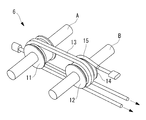
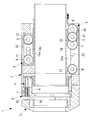
本実施形態に係る医療用マニピュレータ1は、図1に示されるように、医療用ステープラ(以下、医療用ステープラ1ともいう。)であって、細長い管状の支持部材2と、該支持部材2の先端に支持部材2の長手軸に沿って移動可能に支持されたアンビル3と、アンビル3に対向して配置され、同じく支持部材2の先端に長手軸方向に移動可能に支持されたプッシャ(エンドエフェクタ、押出部材)4と、アンビル3を移動させるアンビル駆動機構5と、プッシャ4を移動させるプッシャ駆動機構6とを備えている。 Amedical manipulator 1 according to an embodiment of the present invention will be described below with reference to the drawings.
As shown in FIG. 1, themedical manipulator 1 according to the present embodiment is a medical stapler (hereinafter also referred to as a medical stapler 1), which is an elongated tubular support member 2, and the support member 2. An anvil 3 supported at the tip so as to be movable along the longitudinal axis of the support member 2, and a pusher (end) which is disposed opposite the anvil 3 and is supported at the tip of the support member 2 so as to be movable in the longitudinal axis direction. An anvil driving mechanism 5 for moving the anvil 3, and a pusher driving mechanism 6 for moving the pusher 4.
本実施形態に係る医療用マニピュレータ1は、図1に示されるように、医療用ステープラ(以下、医療用ステープラ1ともいう。)であって、細長い管状の支持部材2と、該支持部材2の先端に支持部材2の長手軸に沿って移動可能に支持されたアンビル3と、アンビル3に対向して配置され、同じく支持部材2の先端に長手軸方向に移動可能に支持されたプッシャ(エンドエフェクタ、押出部材)4と、アンビル3を移動させるアンビル駆動機構5と、プッシャ4を移動させるプッシャ駆動機構6とを備えている。 A
As shown in FIG. 1, the
プッシャ4の先端側には多数のステープル7を収容するカセット8が配置されている。また、プッシャ4はカッター9を支持していて、プッシャ4がプッシャ駆動機構6によって長手軸方向先端側に向かって押し出されることで、カセット8に収容されている複数のステープル7を一度に押し出して組織を接合し、接合された組織をカッター9によって切断するようになっている。
A cassette 8 for accommodating a large number of staples 7 is disposed on the front end side of the pusher 4. Further, the pusher 4 supports the cutter 9, and the pusher 4 is pushed toward the front end side in the longitudinal axis direction by the pusher driving mechanism 6, thereby pushing out the plurality of staples 7 accommodated in the cassette 8 at a time. The tissue is joined, and the joined tissue is cut by the cutter 9.
アンビル3は、カセット8に支持された各ステープル7に対向する位置に、プッシャ4によって押し出されてきたステープル7を受けて変形させる複数の凹部10を備えている。アンビル3は、アンビル駆動機構5によって長手軸方向基端側に向かう力を付与されることで、プッシャ4からの力を受けとめて、プッシャ4との間でステープル7を変形させるようになっている。
The anvil 3 is provided with a plurality of recesses 10 for receiving and deforming the staples 7 pushed out by the pusher 4 at positions facing the staples 7 supported by the cassette 8. The anvil 3 is configured to receive a force from the pusher 4 and deform the staple 7 with the pusher 4 by being given a force toward the proximal side in the longitudinal axis direction by the anvil drive mechanism 5. .
プッシャ駆動機構6は、図1および図2に示されるように、支持部材2の先端に固定され、長手軸に直交する方向に延びる固定軸線A回りに回転可能に支持された固定プーリ11と、プッシャ4に固定され、固定軸線Aよりも基端側に、固定軸線Aと平行間隔を開けて配置された可動軸線(第1軸線)B回りに回転可能に支持された可動プーリ(第1牽引プーリ)12と、固定プーリ11および可動プーリ12に巻き掛けられた押出用ワイヤ(第1ワイヤ)13とを備えている。
As shown in FIGS. 1 and 2, the pusher drive mechanism 6 is fixed to the tip of the support member 2, and fixed pulley 11 supported rotatably around a fixed axis A extending in a direction perpendicular to the longitudinal axis. A movable pulley (first traction) fixed to the pusher 4 and supported so as to be rotatable about a movable axis (first axis) B disposed at a base end side with respect to the fixed axis A and spaced apart from the fixed axis A. Pulley) 12 and an extrusion wire (first wire) 13 wound around the fixed pulley 11 and the movable pulley 12.
押出用ワイヤ13は、先端が支持部材2に固定され、可動プーリ12と固定プーリ11との間で2回巻き掛けられた後に、支持部材2の長手軸方向基端側に延びて、支持部材2の基端側から支持部材2の外部に引き出され、図示しない操作部に接続されている。操作部は、操作者によって操作され、押出用ワイヤ13を基端側に牽引する牽引力が加えられるようになっている。
The extrusion wire 13 is fixed to the support member 2 at the distal end, wound twice between the movable pulley 12 and the fixed pulley 11, and then extended to the proximal end side in the longitudinal axis direction of the support member 2. 2 is pulled out from the base end side of the support member 2 and connected to an operation unit (not shown). The operation unit is operated by an operator, and a pulling force that pulls the extrusion wire 13 toward the proximal end side is applied.
図2に示されるように、可動軸線Bには牽引用プーリ14が回転可能に支持されており、該牽引用プーリ14には、牽引用ワイヤ15が巻き掛けられている。牽引用ワイヤ15は、先端が支持部材2に固定され、牽引用プーリ14に巻き掛けられた後に、支持部材2の長手軸方向に延びて、支持部材2の基端側から支持部材2の外部に引き出され、図示しない操作部に接続されている。
2, a pulling pulley 14 is rotatably supported on the movable axis B, and a pulling wire 15 is wound around the pulling pulley 14. The traction wire 15 is fixed to the support member 2 at the distal end and wound around the pulling pulley 14, and then extends in the longitudinal axis direction of the support member 2, and extends from the base end side of the support member 2 to the outside of the support member 2. And is connected to an operation unit (not shown).
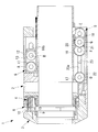
プッシャ4には、図1に示されるように、長手軸方向に沿って延び、固定プーリ11の車軸Aを貫通させるスリット16aが設けられている。また、支持部材2には、図3に示されるように、長手軸方向に沿って延び、可動プーリ12の車軸Bを挿入状態に配置するスリット16bが設けられている。
As shown in FIG. 1, the pusher 4 is provided with a slit 16 a extending along the longitudinal axis direction and passing through the axle A of the fixed pulley 11. Further, as shown in FIG. 3, the support member 2 is provided with a slit 16b extending along the longitudinal axis direction and arranging the axle B of the movable pulley 12 in an inserted state.
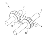
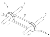
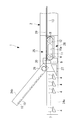
アンビル駆動機構5は、図1、図4および図5に示されるように、支持部材2の先端に長手軸方向に間隔を開けて固定され、長手軸に直交する方向に平行に延びる2つの固定軸線D,E回りにそれぞれ回転可能に支持された2つの固定プーリ17,18と、2つの固定軸線D,Eの間に、固定軸線D,Eと平行間隔を開けて配置され、アンビル3に固定された2つの平行な可動軸線(第2軸線)F,G回りに回転可能に支持された2つの可動プーリ(第2牽引プーリ)19,20と、固定プーリ17,18および可動プーリ19,20に巻き掛けられた牽引用ワイヤ(第2ワイヤ)21および押出用ワイヤ(牽引手段)22とを備えている。
As shown in FIGS. 1, 4, and 5, the anvil drive mechanism 5 is fixed to the front end of the support member 2 with a space in the longitudinal axis direction and extending in parallel to the direction perpendicular to the longitudinal axis. Between the two fixed pulleys 17 and 18 supported rotatably around the axes D and E, respectively, and the two fixed axes D and E, the fixed axes D and E are arranged at a distance from the fixed pulleys D and E. Two fixed movable movable axes (second axes) F and G, two movable pulleys (second traction pulleys) 19 and 20 supported so as to be rotatable, fixed pulleys 17 and 18 and movable pulley 19, A traction wire (second wire) 21 and an extrusion wire (traction device) 22 wound around 20 are provided.
牽引用ワイヤ21は、図4に示されるように、先端が支持部材2に固定され、一方の可動プーリ19と基端側の固定プーリ18との間に2回巻き掛けられた後に、支持部材2の長手軸方向基端側に延びて、支持部材2の基端側から支持部材2の外部に引き出され、図示しない操作部に接続されている。
押出用ワイヤ22は、図5に示されるように、先端が支持部材2に固定され、他方の可動プーリ20に1回巻き掛けられた後に先端側の固定プーリ17によって折り返され、支持部材2の長手軸方向基端側に延びて、支持部材2の基端側から支持部材2の外部に引き出され、図示しない操作部に接続されている。 As shown in FIG. 4, the pullingwire 21 has its distal end fixed to the support member 2, and is wound twice between one movable pulley 19 and the fixed pulley 18 on the proximal end side. 2 extends to the base end side in the longitudinal axis direction, is pulled out of the support member 2 from the base end side of the support member 2, and is connected to an operation unit (not shown).
As shown in FIG. 5, theextrusion wire 22 is fixed to the support member 2 at the tip, wound around the other movable pulley 20 once, and then folded back by the fixed pulley 17 on the tip side. It extends to the base end side in the longitudinal axis direction, is pulled out of the support member 2 from the base end side of the support member 2, and is connected to an operation unit (not shown).
押出用ワイヤ22は、図5に示されるように、先端が支持部材2に固定され、他方の可動プーリ20に1回巻き掛けられた後に先端側の固定プーリ17によって折り返され、支持部材2の長手軸方向基端側に延びて、支持部材2の基端側から支持部材2の外部に引き出され、図示しない操作部に接続されている。 As shown in FIG. 4, the pulling
As shown in FIG. 5, the
アンビル3にも、図3に示されるように、長手軸方向に沿って延び、先端側の固定プーリ17の車軸Dを貫通させるスリット23aが設けられている。また、支持部材2には、図1に示されるように、長手軸方向に沿って延び、可動プーリ19の車軸Fと可動プーリ20の車軸Gの少なくとも一方を挿入状態に配置するスリット23が設けられている。
As shown in FIG. 3, the anvil 3 is also provided with a slit 23 a that extends along the longitudinal axis direction and penetrates the axle D of the fixed pulley 17 on the front end side. As shown in FIG. 1, the support member 2 is provided with a slit 23 that extends along the longitudinal axis direction and that arranges at least one of the axle F of the movable pulley 19 and the axle G of the movable pulley 20 in an inserted state. It has been.
このように構成された本実施形態に係る医療用ステープラ1の作用について以下に説明する。
本実施形態に係る医療用ステープラ1を用いて、患者の体内の組織を接合するには、医療用ステープラ1の先端部を体内に配置し、図1に示されるようにカセット8の先端面とアンビル3とを長手軸方向に離間させた状態で、カセット8とアンビル3との間に接合すべき組織を挿入する。この状態で操作部を操作してアンビル駆動機構5に備えられた牽引用ワイヤ21を基端側に牽引する牽引力を加える。なお、操作部の操作を介して、牽引用ワイヤ21を手動で牽引してもよいし、操作部の操作を介して、モータを作動させて電動で牽引してもよい。 The operation of themedical stapler 1 according to this embodiment configured as described above will be described below.
In order to join tissues in a patient's body using themedical stapler 1 according to the present embodiment, the distal end portion of the medical stapler 1 is disposed in the body, and as shown in FIG. A tissue to be joined is inserted between the cassette 8 and the anvil 3 with the anvil 3 being spaced apart in the longitudinal axis direction. In this state, the operating portion is operated to apply a pulling force that pulls the pulling wire 21 provided in the anvil drive mechanism 5 to the base end side. Note that the pulling wire 21 may be manually pulled through the operation of the operation unit, or may be pulled electrically by operating the motor through the operation of the operation unit.
本実施形態に係る医療用ステープラ1を用いて、患者の体内の組織を接合するには、医療用ステープラ1の先端部を体内に配置し、図1に示されるようにカセット8の先端面とアンビル3とを長手軸方向に離間させた状態で、カセット8とアンビル3との間に接合すべき組織を挿入する。この状態で操作部を操作してアンビル駆動機構5に備えられた牽引用ワイヤ21を基端側に牽引する牽引力を加える。なお、操作部の操作を介して、牽引用ワイヤ21を手動で牽引してもよいし、操作部の操作を介して、モータを作動させて電動で牽引してもよい。 The operation of the
In order to join tissues in a patient's body using the
牽引用ワイヤ21が牽引されると、図6に示されるように、牽引用ワイヤ21に発生した張力が一方の可動プーリ19の可動軸線Fを挟んだ両側に作用し、可動プーリ19が、動滑車として機能して、基端側に牽引される。可動プーリ19と固定プーリ18との間には牽引用ワイヤ21が2回巻き掛けられているので、可動プーリ19には片側2本ずつ、合計4本の牽引用ワイヤ21に発生した張力が、可動プーリ19を基端側に牽引するように、略同一方向に作用する。これにより、可動プーリ19の可動軸線Fが固定されたアンビル3が、操作部によって加えた操作力量の4倍の牽引力で基端側に牽引され、アンビル3とカセット8の先端面との間に組織が挟まれる。
When the pulling wire 21 is pulled, as shown in FIG. 6, the tension generated in the pulling wire 21 acts on both sides of the movable axis 19 of one movable pulley 19, and the movable pulley 19 moves. It functions as a pulley and is pulled to the proximal side. Since the pulling wire 21 is wound twice between the movable pulley 19 and the fixed pulley 18, the tension generated in the total of four pulling wires 21, two on each side, on the movable pulley 19, It acts in substantially the same direction so as to pull the movable pulley 19 toward the base end side. As a result, the anvil 3 to which the movable axis F of the movable pulley 19 is fixed is pulled to the base end side by a traction force that is four times the operation force applied by the operation portion, and between the anvil 3 and the front end surface of the cassette 8. An organization is caught.
次いで、図3に示されるように、操作部を操作して、プッシャ駆動機構6に備えられた押出用ワイヤ13を基端側に牽引する。押出用ワイヤ13が牽引されると、押出用ワイヤ13に発生した張力が可動プーリ12の可動軸線Bを挟んだ両側に作用し、可動プーリ12が先端側に牽引される。可動プーリ12と固定プーリ11との間には押出用ワイヤ13が2回巻き掛けられているので、可動プーリ12には片側2本ずつ、合計4本の押出用ワイヤ13に発生した張力が、可動プーリ12を先端側に押し出すように、略同一方向に作用する。
Next, as shown in FIG. 3, the operation unit is operated to pull the extrusion wire 13 provided in the pusher drive mechanism 6 to the proximal end side. When the extrusion wire 13 is pulled, the tension generated in the extrusion wire 13 acts on both sides of the movable axis B of the movable pulley 12, and the movable pulley 12 is pulled toward the tip side. Since the extrusion wire 13 is wound twice between the movable pulley 12 and the fixed pulley 11, the tension generated in the four extrusion wires 13 in total, two on each side of the movable pulley 12, It acts in substantially the same direction so as to push the movable pulley 12 toward the tip side.
これにより、可動プーリ12の可動軸線Bが固定されたプッシャ4が、操作部によって加えた操作力量の4倍の押出力で先端側に押し出され、プッシャ4に支持された複数のステープル7が一度に先端側に向かって押し出される。
プッシャ4によって押し出された各ステープル7は、その尖端によって組織を長手軸方向に貫通し、アンビル3に設けられた凹部10によって変形させられることにより組織を接合する。
また、プッシャ4に備えられたカッター9が長手軸方向の先端に向かって押し出されることにより、接合された組織がカッター9によって切断され、処置が終了する。 As a result, thepusher 4 to which the movable axis B of the movable pulley 12 is fixed is pushed out to the front end side with a pushing force four times the amount of operation force applied by the operation unit, and the plurality of staples 7 supported by the pusher 4 are once. It is pushed out toward the tip side.
Eachstaple 7 pushed out by the pusher 4 penetrates the tissue in the longitudinal axis direction by its tip, and is deformed by the recess 10 provided in the anvil 3 to join the tissues.
Further, thecutter 9 provided in the pusher 4 is pushed out toward the distal end in the longitudinal axis direction, whereby the joined tissue is cut by the cutter 9 and the treatment is completed.
プッシャ4によって押し出された各ステープル7は、その尖端によって組織を長手軸方向に貫通し、アンビル3に設けられた凹部10によって変形させられることにより組織を接合する。
また、プッシャ4に備えられたカッター9が長手軸方向の先端に向かって押し出されることにより、接合された組織がカッター9によって切断され、処置が終了する。 As a result, the
Each
Further, the
この場合において、本実施形態に係る医療用ステープラ1によれば、プッシャ駆動機構6によって押出用ワイヤ13に加えられた操作力量が4倍に増幅されて複数のステープル7が押し出されるとともにカッター9によって組織が切断されるので、小さい操作力量を加えるだけで済む。その結果、負担を大幅に軽減することができるという利点がある。
In this case, according to the medical stapler 1 according to the present embodiment, the operation force applied to the extrusion wire 13 by the pusher driving mechanism 6 is amplified four times to push out the plurality of staples 7 and to the cutter 9. Since the tissue is cut, it is only necessary to apply a small amount of operating force. As a result, there is an advantage that the burden can be greatly reduced.
特に、支持部材2が、長尺かつ軟性の材質からなるチューブ状である場合に、目標部位に到達するまでの経路において湾曲させられると、支持部材2と内部のワイヤ13,15,21,22との摩擦が増大して、大きな操作力量を加える必要があるが、本実施形態によれば、摩擦によって張力が減衰させられても、プッシャ駆動機構6によって増幅された大きな力で、より確実にプッシャ4を押し出すことができるという利点がある。
In particular, when the support member 2 has a tube shape made of a long and soft material, if the support member 2 is bent in the path to reach the target site, the support member 2 and the internal wires 13, 15, 21, and 22 are used. However, according to this embodiment, even if the tension is attenuated by the friction, the large force amplified by the pusher drive mechanism 6 can be used more reliably. There is an advantage that the pusher 4 can be pushed out.
また、本実施形態においては、アンビル駆動機構5によって牽引用ワイヤ21に加えられた操作力量が4倍に増幅されてアンビル3が基端側に牽引されるので、大きな力でプッシャ4により押し出された複数のステープル7およびカッター9の力を受け止めることができる。特に、牽引用ワイヤ21と押出用ワイヤ13の巻き数を同じくすることにより、アンビル3を基端側に牽引する力の増幅率を、プッシャ4を先端側に押し出す力の増幅率と等しく設定しているので、大きな力でプッシャ4により押し出された複数のステープル7およびカッター9の力をアンビル3によってより確実に受け止めて、組織の接合および切断をより確実に行うことができる。
Further, in this embodiment, the amount of operating force applied to the pulling wire 21 by the anvil drive mechanism 5 is amplified four times and the anvil 3 is pulled to the proximal end side, so that it is pushed out by the pusher 4 with a large force. Further, the force of the plurality of staples 7 and the cutter 9 can be received. In particular, by making the traction wire 21 and the extrusion wire 13 the same number of turns, the amplification factor of the force that pulls the anvil 3 to the proximal end side is set equal to the amplification factor of the force that pushes the pusher 4 to the distal end side. Therefore, the force of the plurality of staples 7 and the cutter 9 pushed out by the pusher 4 with a large force can be more reliably received by the anvil 3, and the tissue can be joined and cut more reliably.
なお、本実施形態においては、プッシャ駆動機構6の可動プーリ12には牽引用プーリ14が固定されているので、牽引用プーリ14に巻き掛けられた牽引用ワイヤ15を基端側に牽引することにより、プッシャ4を基端側に引き戻すことができる。
また、アンビル駆動機構5の先端側の固定プーリ17と他方の可動プーリ20との間に巻き掛けられた押出用ワイヤ22を牽引することにより、アンビル3を先端側に押し出すことができ、アンビル3とプッシャ4との間の間隔を広げることができる。 In the present embodiment, since the pullingpulley 14 is fixed to the movable pulley 12 of the pusher driving mechanism 6, the pulling wire 15 wound around the pulling pulley 14 is pulled to the proximal end side. Thus, the pusher 4 can be pulled back to the base end side.
Further, by pulling theextrusion wire 22 wound between the fixed pulley 17 on the distal end side of the anvil drive mechanism 5 and the other movable pulley 20, the anvil 3 can be pushed out toward the distal end side. And the pusher 4 can be widened.
また、アンビル駆動機構5の先端側の固定プーリ17と他方の可動プーリ20との間に巻き掛けられた押出用ワイヤ22を牽引することにより、アンビル3を先端側に押し出すことができ、アンビル3とプッシャ4との間の間隔を広げることができる。 In the present embodiment, since the pulling
Further, by pulling the
プッシャ駆動機構6によるプッシャ4の基端側への引き戻しおよびアンビル駆動機構5によるアンビル3の先端側への押し出しについては、逆方向への移動ほど大きな操作力量は必要ないので、増幅しなくてもよいが、増幅する機構を設けた方が、操作力量を低減し、摩擦による減衰があっても確実に作動させることができるので好ましい。
The pusher drive mechanism 6 pulls back the pusher 4 to the proximal end side and the anvil drive mechanism 5 pushes the anvil 3 to the distal end side, so that a large amount of operation force is not required as it moves in the opposite direction, and therefore it does not need to be amplified. However, it is preferable to provide a mechanism for amplifying, because the amount of operation force can be reduced and the operation can be ensured even if there is frictional attenuation.
また、本実施形態においては、アンビル3の可動プーリ19に巻き掛けられる牽引用ワイヤ21の巻き数をプッシャ4の可動プーリ12に巻き掛けられる押出用ワイヤ13の巻き数と等しくして、増幅率を等しくしたが、アンビル3側の巻き数を多くすることで増幅率をより多くしてもよい。また、巻き数によって増幅率を調整することに代えて、可動プーリ19および牽引用ワイヤ21の組数および可動プーリ20および押出用ワイヤ22の組数を複数組にしてもよい。可動プーリ19,20に巻かれるワイヤ21,22の巻き数が多くなると摩擦により効率が低減するため、可動プーリ19,20を分離してそれぞれ増幅することが好ましい。
Further, in the present embodiment, the number of turns of the pulling wire 21 wound around the movable pulley 19 of the anvil 3 is made equal to the number of turns of the extrusion wire 13 wound around the movable pulley 12 of the pusher 4 to increase the amplification factor. However, the amplification factor may be increased by increasing the number of turns on the anvil 3 side. Further, instead of adjusting the amplification factor by the number of turns, the number of sets of the movable pulley 19 and the pulling wire 21 and the number of sets of the movable pulley 20 and the pushing wire 22 may be set to a plurality. As the number of turns of the wires 21 and 22 wound around the movable pulleys 19 and 20 increases, the efficiency decreases due to friction. Therefore, the movable pulleys 19 and 20 are preferably separated and amplified.
また、本実施形態においては、医療用マニピュレータ1として、サーキュラステープラのような医療用ステープラを用いた例を説明したが、これに代えて、図7に示されるように、リニアステープラのような医療用ステープラを採用してもよい。
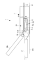
この場合、医療用マニピュレータ1は、支持部材2と、該支持部材2の先端に支持部材2の長手軸に沿って設けられた下ジョー(カセット)24aと、支持部材2の先端に揺動可能に支持された上ジョー(アンビル)24bと、該上ジョー24bを揺動させるジョー駆動機構(アンビル駆動機構)25と、プッシャ4と、プッシャ4を移動させるプッシャ駆動機構26と、該プッシャ駆動機構26からの力をプッシャ4に伝達する斜面を有するスライダ27とを備えている。 In the present embodiment, an example in which a medical stapler such as a circular taper is used as themedical manipulator 1 has been described. Instead, as shown in FIG. 7, a medical device such as a linear stapler is used. A stapler may be used.
In this case, themedical manipulator 1 is swingable at the support member 2, the lower jaw (cassette) 24 a provided at the tip of the support member 2 along the longitudinal axis of the support member 2, and the tip of the support member 2. The upper jaw (anvil) 24b supported by the upper jaw 24, the jaw drive mechanism (anvil drive mechanism) 25 for swinging the upper jaw 24b, the pusher 4, the pusher drive mechanism 26 for moving the pusher 4, and the pusher drive mechanism 26 and a slider 27 having an inclined surface that transmits the force from the pusher 4 to the pusher 4.
この場合、医療用マニピュレータ1は、支持部材2と、該支持部材2の先端に支持部材2の長手軸に沿って設けられた下ジョー(カセット)24aと、支持部材2の先端に揺動可能に支持された上ジョー(アンビル)24bと、該上ジョー24bを揺動させるジョー駆動機構(アンビル駆動機構)25と、プッシャ4と、プッシャ4を移動させるプッシャ駆動機構26と、該プッシャ駆動機構26からの力をプッシャ4に伝達する斜面を有するスライダ27とを備えている。 In the present embodiment, an example in which a medical stapler such as a circular taper is used as the
In this case, the
ジョー駆動機構25は、上ジョー24bに固定され、支持部材2に対して回転可能な固定プーリ28と、一端が固定プーリ28に固定されている牽引用ワイヤ(第2ワイヤ)29とを備えている。
牽引用ワイヤ29は、一端が固定されている固定プーリ28に巻き掛けられた後に、支持部材2の長手軸方向に延びて、支持部材2の基端側から支持部材2の外部に引き出され、図示しない操作部に接続されている。 Thejaw drive mechanism 25 includes a fixed pulley 28 fixed to the upper jaw 24 b and rotatable with respect to the support member 2, and a pulling wire (second wire) 29 having one end fixed to the fixed pulley 28. Yes.
The pullingwire 29 is wound around a fixed pulley 28 having one end fixed, and then extends in the longitudinal axis direction of the support member 2 and is pulled out of the support member 2 from the base end side of the support member 2. It is connected to an operation unit (not shown).
牽引用ワイヤ29は、一端が固定されている固定プーリ28に巻き掛けられた後に、支持部材2の長手軸方向に延びて、支持部材2の基端側から支持部材2の外部に引き出され、図示しない操作部に接続されている。 The
The pulling
プッシャ駆動機構26は、固定プーリ11と、可動プーリ12と、押出用ワイヤ13と、可動プーリ12の可動によって支持部材2の長手軸に沿う方向に移動する駆動部材30とを備えている。
The pusher drive mechanism 26 includes a fixed pulley 11, a movable pulley 12, an extrusion wire 13, and a drive member 30 that moves in a direction along the longitudinal axis of the support member 2 by the movement of the movable pulley 12.
患者の体内の組織を接合するには、下ジョー24aと上ジョー24bとの間に接合すべき組織を挿入し、この状態で操作部を操作してジョー駆動機構25に備えられた牽引用ワイヤ29を基端側に牽引する。牽引用ワイヤ29が牽引されると、牽引用ワイヤ29に発生した張力が固定プーリ28に伝達され、固定プーリ28が回転する。固定プーリ28の回転によって、上ジョー24bが揺動して下ジョー24aに近づき、下ジョー24aと上ジョー24bとの間に組織が挟まれる。
In order to join tissues in the patient's body, a tissue to be joined is inserted between the lower jaw 24a and the upper jaw 24b, and the operating portion is operated in this state to pull the pulling wire provided in the jaw drive mechanism 25. 29 is pulled to the proximal side. When the pulling wire 29 is pulled, the tension generated in the pulling wire 29 is transmitted to the fixed pulley 28, and the fixed pulley 28 rotates. Due to the rotation of the fixed pulley 28, the upper jaw 24b swings and approaches the lower jaw 24a, and the tissue is sandwiched between the lower jaw 24a and the upper jaw 24b.
次いで、操作部を操作して、プッシャ駆動機構26に備えられた押出用ワイヤ13を基端側に牽引すると、可動プーリ12が先端側に牽引される。可動プーリ12が先端側に牽引されると、駆動部材30も先端側に牽引される。先端側に牽引された駆動部材30がスライダ27を先端側に押し出すように作用することにより、スライダ27の斜面によってプッシャ4が先端側に押し出されて下ジョー24a表面の図示しない開口からステープル7が上ジョー24bに向かって押し出され、ステープル7が組織を接合する。
また、駆動部材30に備えられたカッター9が長手軸方向の先端に向かって押し出されることにより、接合された組織がカッター9によって切断され、処置が終了する。 Next, when the operation unit is operated to pull theextrusion wire 13 provided in the pusher drive mechanism 26 to the proximal end side, the movable pulley 12 is pulled to the distal end side. When the movable pulley 12 is pulled toward the distal end side, the drive member 30 is also pulled toward the distal end side. The drive member 30 pulled toward the distal end acts to push the slider 27 toward the distal end, so that the pusher 4 is pushed toward the distal end by the inclined surface of the slider 27 and the staple 7 is released from an opening (not shown) on the surface of the lower jaw 24a. Pushed toward the upper jaw 24b, the staple 7 joins the tissue.
Moreover, when thecutter 9 provided in the drive member 30 is pushed out toward the distal end in the longitudinal axis direction, the joined tissue is cut by the cutter 9 and the treatment is completed.
また、駆動部材30に備えられたカッター9が長手軸方向の先端に向かって押し出されることにより、接合された組織がカッター9によって切断され、処置が終了する。 Next, when the operation unit is operated to pull the
Moreover, when the
また、本実施形態においては、医療用マニピュレータ1として、医療用ステープラに代えて、図8に示されるように、エナジー処置具を採用してもよい。図中、符号31は、血管等の組織をエナジーにより封止可能なエナジー部、符号32はエナジー部31にエナジーを伝達するエナジー伝達部である。
In the present embodiment, an energy treatment tool may be employed as the medical manipulator 1 as shown in FIG. 8 instead of the medical stapler. In the figure, reference numeral 31 denotes an energy part capable of sealing a tissue such as a blood vessel with energy, and reference numeral 32 denotes an energy transmission part that transmits energy to the energy part 31.
1 医療用マニピュレータ
2 支持部材
3 アンビル
4 プッシャ(エンドエフェクタ、押出部材)
7 ステープル
12 可動プーリ(第1牽引プーリ)
13 押出用ワイヤ(第1ワイヤ)
16b スリット
19,20 可動プーリ(第2牽引プーリ)
21,29 牽引用ワイヤ(第2ワイヤ)
22 押出用ワイヤ(牽引手段)
24b 上ジョー(アンビル)
B 可動軸線(第1軸線)
F,G 可動軸線(第2軸線) DESCRIPTION OFSYMBOLS 1 Medical manipulator 2 Support member 3 Anvil 4 Pusher (end effector, extrusion member)
7 Staple 12 Movable pulley (first pulling pulley)
13 Wire for extrusion (first wire)
16b Slit 19, 20 Movable pulley (second pulling pulley)
21, 29 Tow wire (second wire)
22 Extruding wire (traction means)
24b Upper Joe (Anvil)
B Movable axis (first axis)
F, G Movable axis (second axis)
2 支持部材
3 アンビル
4 プッシャ(エンドエフェクタ、押出部材)
7 ステープル
12 可動プーリ(第1牽引プーリ)
13 押出用ワイヤ(第1ワイヤ)
16b スリット
19,20 可動プーリ(第2牽引プーリ)
21,29 牽引用ワイヤ(第2ワイヤ)
22 押出用ワイヤ(牽引手段)
24b 上ジョー(アンビル)
B 可動軸線(第1軸線)
F,G 可動軸線(第2軸線) DESCRIPTION OF
7 Staple 12 Movable pulley (first pulling pulley)
13 Wire for extrusion (first wire)
21, 29 Tow wire (second wire)
22 Extruding wire (traction means)
24b Upper Joe (Anvil)
B Movable axis (first axis)
F, G Movable axis (second axis)
Claims (9)
- 細長い支持部材と、
該支持部材の先端に長手軸方向に移動可能に支持されたエンドエフェクタと、
該エンドエフェクタに固定され前記長手軸に直交する第1軸線回りに回転可能に支持された第1牽引プーリと、
基端が牽引されることにより、前記第1軸線を挟んだ前記第1牽引プーリの両側において略同一方向の張力を前記第1牽引プーリに作用させるように前記第1牽引プーリに巻き掛けられた第1ワイヤとを備える医療用マニピュレータ。 An elongated support member;
An end effector supported at the tip of the support member so as to be movable in the longitudinal axis direction;
A first traction pulley fixed to the end effector and supported rotatably about a first axis perpendicular to the longitudinal axis;
When the base end is pulled, it is wound around the first traction pulley so that tension in substantially the same direction acts on the first traction pulley on both sides of the first traction pulley across the first axis. A medical manipulator comprising a first wire. - 前記支持部材に、前記第1牽引プーリの車軸を長手軸方向に移動可能に支持するスリットを備える請求項1に記載の医療用マニピュレータ。 The medical manipulator according to claim 1, wherein the support member includes a slit that supports the axle of the first pulling pulley so as to be movable in the longitudinal axis direction.
- 前記第1牽引プーリおよび前記第1ワイヤを2組以上備える請求項1または請求項2に記載の医療用マニピュレータ。 The medical manipulator according to claim 1 or 2, comprising two or more sets of the first pulling pulley and the first wire.
- 前記エンドエフェクタが、ステープルを押し出す押出部材である請求項1から請求項3のいずれかに記載の医療用マニピュレータ。 The medical manipulator according to any one of claims 1 to 3, wherein the end effector is an extrusion member that pushes out staples.
- 前記支持部材の先端に長手軸方向に移動可能に支持され、前記押出部材によって前記長手軸方向先端側に押し出された前記ステープルを変形させるアンビルと、
該アンビルに固定され前記長手軸に直交する第2軸線回りに回転可能に支持された第2牽引プーリと、
基端が牽引されることにより、前記第2軸線を挟んだ前記第2牽引プーリの両側において前記長手軸方向基端側に向かう張力を前記第2牽引プーリに作用させるように前記第2牽引プーリに巻き掛けられた第2ワイヤとを備える請求項4に記載の医療用マニピュレータ。 An anvil that is supported at the distal end of the support member so as to be movable in the longitudinal axis direction, and deforms the staple pushed out by the pushing member toward the distal end side in the longitudinal axis direction;
A second pulling pulley fixed to the anvil and supported rotatably around a second axis perpendicular to the longitudinal axis;
By pulling the base end, the second pulling pulley is configured so that the tension toward the base end in the longitudinal axis direction acts on the second pulling pulley on both sides of the second pulling pulley across the second axis. The medical manipulator according to claim 4, further comprising a second wire wound around. - 前記第2牽引プーリおよび前記第2ワイヤを2組以上備える請求項5に記載の医療用マニピュレータ。 The medical manipulator according to claim 5, comprising two or more sets of the second pulling pulley and the second wire.
- 前記第2ワイヤの牽引により前記アンビルを前記長手軸方向基端側に移動させる力が、
前記第1ワイヤの牽引により前記押出部材を前記長手軸方向先端側に移動させる力以上である請求項5または請求項6に記載の医療用マニピュレータ。 A force for moving the anvil toward the proximal side in the longitudinal axis direction by pulling the second wire,
The medical manipulator according to claim 5 or 6, wherein the force is greater than or equal to a force for moving the push-out member toward the distal end side in the longitudinal axis direction by pulling the first wire. - 前記第2牽引プーリにおける前記第2ワイヤの巻き数が、前記第1牽引プーリにおける前記第1ワイヤの巻き数以上である請求項7に記載の医療用マニピュレータ。 The medical manipulator according to claim 7, wherein the number of turns of the second wire in the second pulling pulley is equal to or greater than the number of turns of the first wire in the first pulling pulley.
- 前記アンビルを前記支持部材に対して前記長手軸方向先端側に牽引する牽引手段を備える請求項5から請求項8のいずれかに記載の医療用マニピュレータ。
The medical manipulator according to any one of claims 5 to 8, further comprising pulling means for pulling the anvil toward the distal end side in the longitudinal axis direction with respect to the support member.
Priority Applications (6)
| Application Number | Priority Date | Filing Date | Title |
|---|---|---|---|
| PCT/JP2016/084830 WO2018096625A1 (en) | 2016-11-24 | 2016-11-24 | Medical manipulator |
| JP2018552397A JP6875416B2 (en) | 2016-11-24 | 2017-05-10 | Medical manipulator |
| PCT/JP2017/017714 WO2018096711A1 (en) | 2016-11-24 | 2017-05-10 | Medical manipulator |
| DE112017003829.4T DE112017003829T5 (en) | 2016-11-24 | 2017-05-10 | Medical manipulator |
| CN201780057554.7A CN109715084B (en) | 2016-11-24 | 2017-05-10 | Medical manipulator |
| US16/272,023 US11160552B2 (en) | 2016-11-24 | 2019-02-11 | Medical manipulator |
Applications Claiming Priority (1)
| Application Number | Priority Date | Filing Date | Title |
|---|---|---|---|
| PCT/JP2016/084830 WO2018096625A1 (en) | 2016-11-24 | 2016-11-24 | Medical manipulator |
Publications (1)
| Publication Number | Publication Date |
|---|---|
| WO2018096625A1 true WO2018096625A1 (en) | 2018-05-31 |
Family
ID=62195845
Family Applications (2)
| Application Number | Title | Priority Date | Filing Date |
|---|---|---|---|
| PCT/JP2016/084830 WO2018096625A1 (en) | 2016-11-24 | 2016-11-24 | Medical manipulator |
| PCT/JP2017/017714 WO2018096711A1 (en) | 2016-11-24 | 2017-05-10 | Medical manipulator |
Family Applications After (1)
| Application Number | Title | Priority Date | Filing Date |
|---|---|---|---|
| PCT/JP2017/017714 WO2018096711A1 (en) | 2016-11-24 | 2017-05-10 | Medical manipulator |
Country Status (5)
| Country | Link |
|---|---|
| US (1) | US11160552B2 (en) |
| JP (1) | JP6875416B2 (en) |
| CN (1) | CN109715084B (en) |
| DE (1) | DE112017003829T5 (en) |
| WO (2) | WO2018096625A1 (en) |
Families Citing this family (11)
| Publication number | Priority date | Publication date | Assignee | Title |
|---|---|---|---|---|
| US20140005640A1 (en) | 2012-06-28 | 2014-01-02 | Ethicon Endo-Surgery, Inc. | Surgical end effector jaw and electrode configurations |
| CN111466975B (en) * | 2019-01-24 | 2022-04-15 | 苏州英途康医疗科技有限公司 | Surgical instrument and linear stapler |
| CN111466974B (en) | 2019-01-24 | 2021-05-14 | 苏州英途康医疗科技有限公司 | Surgical instrument and linear stapler |
| WO2020180678A1 (en) * | 2019-03-01 | 2020-09-10 | Boston Scientific Scimed, Inc. | Systems, devices, and related methods for fastening tissue |
| US11413102B2 (en) | 2019-06-27 | 2022-08-16 | Cilag Gmbh International | Multi-access port for surgical robotic systems |
| US11723729B2 (en) | 2019-06-27 | 2023-08-15 | Cilag Gmbh International | Robotic surgical assembly coupling safety mechanisms |
| US11607278B2 (en) | 2019-06-27 | 2023-03-21 | Cilag Gmbh International | Cooperative robotic surgical systems |
| US11612445B2 (en) * | 2019-06-27 | 2023-03-28 | Cilag Gmbh International | Cooperative operation of robotic arms |
| US11399906B2 (en) | 2019-06-27 | 2022-08-02 | Cilag Gmbh International | Robotic surgical system for controlling close operation of end-effectors |
| US11547468B2 (en) | 2019-06-27 | 2023-01-10 | Cilag Gmbh International | Robotic surgical system with safety and cooperative sensing control |
| US11931026B2 (en) | 2021-06-30 | 2024-03-19 | Cilag Gmbh International | Staple cartridge replacement |
Citations (5)
| Publication number | Priority date | Publication date | Assignee | Title |
|---|---|---|---|---|
| JPH0833628A (en) * | 1994-02-18 | 1996-02-06 | Ethicon Inc | Jaw assembly for surgical operation apparatus which is operated by cable |
| JP2005526568A (en) * | 2002-05-24 | 2005-09-08 | ボストン サイエンティフィック リミテッド | Full thickness ablation device |
| JP2009106606A (en) * | 2007-10-31 | 2009-05-21 | Terumo Corp | Medical manipulator |
| JP2009268910A (en) * | 2008-05-09 | 2009-11-19 | Tyco Healthcare Group Lp | Variable compression surgical fastener cartridge |
| WO2015137181A1 (en) * | 2014-03-13 | 2015-09-17 | オリンパス株式会社 | Tissue excision device |
Family Cites Families (15)
| Publication number | Priority date | Publication date | Assignee | Title |
|---|---|---|---|---|
| US4573622A (en) * | 1984-10-19 | 1986-03-04 | United States Surgical Corporation | Surgical fastener applying apparatus with variable fastener arrays |
| US5197649A (en) * | 1991-10-29 | 1993-03-30 | The Trustees Of Columbia University In The City Of New York | Gastrointestinal endoscoptic stapler |
| JPH11253389A (en) | 1998-03-16 | 1999-09-21 | Olympus Optical Co Ltd | Endoscope |
| JPH11253390A (en) | 1998-03-16 | 1999-09-21 | Olympus Optical Co Ltd | Endoscope |
| JP4512255B2 (en) | 2000-10-31 | 2010-07-28 | Hoya株式会社 | Endoscope bending operation mechanism |
| US20060116697A1 (en) * | 2004-11-30 | 2006-06-01 | Esophyx, Inc. | Flexible transoral endoscopic gastroesophageal flap valve restoration device and method |
| CN100448410C (en) * | 2005-03-24 | 2009-01-07 | 上海创亿医疗器械技术有限公司 | Tubular digestive tract anastomat |
| US7278563B1 (en) * | 2006-04-25 | 2007-10-09 | Green David T | Surgical instrument for progressively stapling and incising tissue |
| ATE440549T1 (en) | 2006-09-08 | 2009-09-15 | Ethicon Endo Surgery Inc | SURGICAL INSTRUMENT AND ACTUATING DEVICE FOR TRANSMITTING MOTION THEREFOR |
| US8006885B2 (en) * | 2007-04-09 | 2011-08-30 | Tyco Healthcare Group Lp | Surgical stapling apparatus with powered retraction |
| US20080308602A1 (en) | 2007-06-18 | 2008-12-18 | Timm Richard W | Surgical stapling and cutting instruments |
| US8011551B2 (en) * | 2008-07-01 | 2011-09-06 | Tyco Healthcare Group Lp | Retraction mechanism with clutch-less drive for use with a surgical apparatus |
| CN102228386B (en) * | 2010-09-16 | 2012-11-07 | 北京中法派尔特医疗设备有限公司 | Forceps opening assembly with guiding structure and stitching instrument adopting forceps opening assembly |
| JP2015093033A (en) | 2013-11-12 | 2015-05-18 | 住友ベークライト株式会社 | Medical device |
| CN105596049B (en) * | 2016-02-25 | 2017-12-26 | 常州市康迪医用吻合器有限公司 | A kind of hysteroscope Endo-GIA |
-
2016
- 2016-11-24 WO PCT/JP2016/084830 patent/WO2018096625A1/en active Application Filing
-
2017
- 2017-05-10 WO PCT/JP2017/017714 patent/WO2018096711A1/en active Application Filing
- 2017-05-10 JP JP2018552397A patent/JP6875416B2/en active Active
- 2017-05-10 DE DE112017003829.4T patent/DE112017003829T5/en not_active Withdrawn
- 2017-05-10 CN CN201780057554.7A patent/CN109715084B/en active Active
-
2019
- 2019-02-11 US US16/272,023 patent/US11160552B2/en active Active
Patent Citations (5)
| Publication number | Priority date | Publication date | Assignee | Title |
|---|---|---|---|---|
| JPH0833628A (en) * | 1994-02-18 | 1996-02-06 | Ethicon Inc | Jaw assembly for surgical operation apparatus which is operated by cable |
| JP2005526568A (en) * | 2002-05-24 | 2005-09-08 | ボストン サイエンティフィック リミテッド | Full thickness ablation device |
| JP2009106606A (en) * | 2007-10-31 | 2009-05-21 | Terumo Corp | Medical manipulator |
| JP2009268910A (en) * | 2008-05-09 | 2009-11-19 | Tyco Healthcare Group Lp | Variable compression surgical fastener cartridge |
| WO2015137181A1 (en) * | 2014-03-13 | 2015-09-17 | オリンパス株式会社 | Tissue excision device |
Also Published As
| Publication number | Publication date |
|---|---|
| JPWO2018096711A1 (en) | 2019-10-17 |
| JP6875416B2 (en) | 2021-05-26 |
| CN109715084A (en) | 2019-05-03 |
| WO2018096711A1 (en) | 2018-05-31 |
| CN109715084B (en) | 2021-09-14 |
| US20190167267A1 (en) | 2019-06-06 |
| US11160552B2 (en) | 2021-11-02 |
| DE112017003829T5 (en) | 2019-04-25 |
Similar Documents
| Publication | Publication Date | Title |
|---|---|---|
| WO2018096625A1 (en) | Medical manipulator | |
| EP3332717A1 (en) | Treatment device | |
| US9844366B2 (en) | Needle for laparoscopic suturing instrument | |
| WO2015137181A1 (en) | Tissue excision device | |
| JP4510001B2 (en) | Driving force transmission along a bending instrument | |
| EP3320858B1 (en) | Circular surgical stapler with recessed deck | |
| JP5073333B2 (en) | Surgical fasteners and surgical instruments | |
| US7694864B2 (en) | Tissue stapler with positioning mechanism | |
| JP5887315B2 (en) | Remote suture management device and method | |
| JP5815109B2 (en) | Suture device | |
| EP1938761A1 (en) | Suturing device | |
| US20080221604A1 (en) | Tissue shredding device and tissue shredding method | |
| JP2002523171A (en) | Surgical suturing instruments and other uses | |
| EP3178410B1 (en) | Surgical instrument | |
| US7794471B1 (en) | Compliant anastomosis system | |
| US20090259232A1 (en) | Suture device | |
| JP6153692B2 (en) | Medical manipulator | |
| JP6180694B2 (en) | Suture device | |
| EP3520717B1 (en) | Clip removal device | |
| WO2014061505A1 (en) | Treatment tool for endoscope | |
| RU2723729C1 (en) | Surgical device for tissue closure | |
| US20210128155A1 (en) | Surgical clip applier with partial clamping | |
| EP3332716B1 (en) | Suturing device |
Legal Events
| Date | Code | Title | Description |
|---|---|---|---|
| 121 | Ep: the epo has been informed by wipo that ep was designated in this application |
Ref document number: 16922062 Country of ref document: EP Kind code of ref document: A1 |
|
| NENP | Non-entry into the national phase |
Ref country code: DE |
|
| 122 | Ep: pct application non-entry in european phase |
Ref document number: 16922062 Country of ref document: EP Kind code of ref document: A1 |
|
| NENP | Non-entry into the national phase |
Ref country code: JP |