WO2018094829A1 - 交互设备、颜色更换方法及系统 - Google Patents
交互设备、颜色更换方法及系统 Download PDFInfo
- Publication number
- WO2018094829A1 WO2018094829A1 PCT/CN2016/113303 CN2016113303W WO2018094829A1 WO 2018094829 A1 WO2018094829 A1 WO 2018094829A1 CN 2016113303 W CN2016113303 W CN 2016113303W WO 2018094829 A1 WO2018094829 A1 WO 2018094829A1
- Authority
- WO
- WIPO (PCT)
- Prior art keywords
- smart pen
- infrared
- color
- microprocessor
- color replacement
- Prior art date
- Legal status (The legal status is an assumption and is not a legal conclusion. Google has not performed a legal analysis and makes no representation as to the accuracy of the status listed.)
- Ceased
Links
Images




Classifications
-
- H—ELECTRICITY
- H04—ELECTRIC COMMUNICATION TECHNIQUE
- H04N—PICTORIAL COMMUNICATION, e.g. TELEVISION
- H04N21/00—Selective content distribution, e.g. interactive television or video on demand [VOD]
- H04N21/40—Client devices specifically adapted for the reception of or interaction with content, e.g. set-top-box [STB]; Operations thereof
- H04N21/41—Structure of client; Structure of client peripherals
- H04N21/422—Input-only peripherals, i.e. input devices connected to specially adapted client devices, e.g. global positioning system [GPS]
- H04N21/42204—User interfaces specially adapted for controlling a client device through a remote control device; Remote control devices therefor
- H04N21/42206—User interfaces specially adapted for controlling a client device through a remote control device; Remote control devices therefor characterized by hardware details
- H04N21/42221—Transmission circuitry, e.g. infrared [IR] or radio frequency [RF]
-
- H—ELECTRICITY
- H04—ELECTRIC COMMUNICATION TECHNIQUE
- H04N—PICTORIAL COMMUNICATION, e.g. TELEVISION
- H04N21/00—Selective content distribution, e.g. interactive television or video on demand [VOD]
- H04N21/40—Client devices specifically adapted for the reception of or interaction with content, e.g. set-top-box [STB]; Operations thereof
- H04N21/41—Structure of client; Structure of client peripherals
- H04N21/422—Input-only peripherals, i.e. input devices connected to specially adapted client devices, e.g. global positioning system [GPS]
- H04N21/42204—User interfaces specially adapted for controlling a client device through a remote control device; Remote control devices therefor
- H04N21/42206—User interfaces specially adapted for controlling a client device through a remote control device; Remote control devices therefor characterized by hardware details
- H04N21/42225—User interfaces specially adapted for controlling a client device through a remote control device; Remote control devices therefor characterized by hardware details characterized by types of remote control, e.g. universal remote control
-
- H—ELECTRICITY
- H04—ELECTRIC COMMUNICATION TECHNIQUE
- H04N—PICTORIAL COMMUNICATION, e.g. TELEVISION
- H04N21/00—Selective content distribution, e.g. interactive television or video on demand [VOD]
- H04N21/40—Client devices specifically adapted for the reception of or interaction with content, e.g. set-top-box [STB]; Operations thereof
- H04N21/43—Processing of content or additional data, e.g. demultiplexing additional data from a digital video stream; Elementary client operations, e.g. monitoring of home network or synchronising decoder's clock; Client middleware
- H04N21/436—Interfacing a local distribution network, e.g. communicating with another STB or one or more peripheral devices inside the home
- H04N21/4363—Adapting the video stream to a specific local network, e.g. a Bluetooth® network
- H04N21/43637—Adapting the video stream to a specific local network, e.g. a Bluetooth® network involving a wireless protocol, e.g. Bluetooth®, RF or wireless LAN [IEEE 802.11]
Definitions
- the present invention relates to the field of electronic technologies, and in particular, to an interactive device, a color changing method, and a system.
- the smart pen is a multi-function mobile pen with matching operation platform communication compared with the traditional refill.
- FIG. 1 is a frame diagram of a smart pen system in the prior art solution.
- the smart pen 3 is internally integrated with an MCU (Micro Ccontroller Unit) 31 and a first wifi (Wireless-Fidelity) module. 32.
- the MCU 31 and the first wifi module 32 are connected by a USB (Universal Serial Bus) method to implement state control of the first wifi module 32 by the MCU 31.
- the smart pen 3 and the display device 4 use wifi communication, mainly in the 2.4G frequency band.
- the first wifi module 32 of the smart pen 3 is built into the local area network by the second wifi module 41 of the display device 4 via the RF (Radio Frequency) protocol, and the main control chip 42 performs corresponding operations according to the control command issued by the smart pen 3. Implement the corresponding functions.
- RF Radio Frequency
- the prior art solution requires that the smart pen end and the display device end have a built-in wifi module, and the price is relatively high. Because the wifi band is used, the signal is greatly affected by the interference, so that the display device cannot accurately execute the control command sent by the smart pen end, and now Some display devices only display a single color when displaying the smart pen signal.
- an embodiment of the present invention provides an interaction device, a color replacement method, and a system.
- the higher communication quality between the smart pen and the display device enables the display device to accurately receive and execute the color change command sent by the smart pen.
- an embodiment of the present invention provides an interactive device, including a smart pen and a display device, where the smart pen includes: a smart pen microprocessor, a button unit, and a first infrared emitter, the smart pen micro The processor is respectively connected to the button unit and the first infrared emitter;
- the button unit is configured to receive a button operation of a user and send the button to the smart pen microprocessor;
- the smart pen microprocessor is configured to encode a color replacement instruction according to the button operation and transmit the same to the first infrared emitter;
- the first infrared emitter is configured to emit an infrared signal carrying the color replacement instruction
- the display device includes: a touch frame microprocessor, an infrared touch frame and a whole machine main control chip, wherein the infrared touch frame is provided with a second infrared receiver, and the touch frame microprocessor respectively receives the second infrared receiving And the whole machine main control chip is connected;
- the second infrared receiver is configured to receive an infrared signal carrying the color replacement instruction
- the touch frame microprocessor is configured to decode an infrared signal received by the second infrared receiver to obtain the color replacement instruction and send the color to the whole control chip;
- the whole machine main control chip is configured to replace the signal display color of the smart pen on the display surface of the display device according to the color replacement instruction.
- the embodiment of the present invention further provides a color replacement method, which is used in the foregoing interaction device, and includes:
- the smart pen microprocessor receives the key operation input by the button unit, and encodes a color replacement instruction according to the button operation;
- the smart pen microprocessor transmits the encoded color replacement command to the first infrared emitter to transmit an infrared signal carrying the encoded color replacement command through the first infrared emitter;
- the touch frame microprocessor decodes the infrared signal received by the second infrared receiver to obtain the color replacement instruction
- the touch frame microprocessor sends the color replacement command to the whole machine main control chip, so that the whole machine main control chip replaces the signal display color of the smart pen on the display surface of the display device according to the color replacement instruction.
- the embodiment of the present invention further provides a color replacement system, which is used in the foregoing interaction device, and the smart pen microprocessor includes:
- a first encoding module configured to receive a button operation input by the button unit, and encode a color replacement instruction according to the button operation
- a first transmitting module configured to transmit a coded color replacement command to the first infrared emitter, to transmit an infrared signal carrying the encoded color replacement command by the first infrared emitter;
- the touch frame microprocessor includes:
- a second decoding module configured to decode an infrared signal received by the second infrared receiver to obtain the color replacement instruction
- the instruction sending module is configured to send the color replacement instruction to the whole machine main control chip, so that the whole machine main control chip replaces the signal display color of the smart pen on the display surface of the display device according to the color replacement instruction.
- the interaction device, the color replacement method and the system provided by the embodiment of the invention send the received button operation to the smart pen microprocessor through the button unit of the smart pen, and the smart pen microprocessor encodes the color replacement instruction corresponding to the button operation and Sending to the first infrared emitter, so that the first infrared emitter sends an infrared signal carrying a color replacement command, and the touch frame microprocessor decodes the infrared signal received by the second infrared receiver to obtain a color replacement command and sends the color to the whole machine.
- the main control chip enables the main control chip to replace the signal display color of the smart pen on the display surface of the display device according to the color replacement instruction, realizing the smart pen and the intersection Infrared communication between the display devices of each other reduces the production cost of the product, reduces the interference of external signals, and at the same time realizes the replacement of the smart pen signal display color in the display device, and simplifies the operation of the smart pen.
- FIG. 1 is a frame diagram of a smart pen system in a prior art solution
- FIG. 2 is a schematic structural diagram of an interaction device according to Embodiment 1 of the present invention.
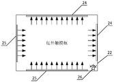
- FIG. 3 is a schematic structural diagram of an infrared touch frame according to Embodiment 1 of the present invention.
- FIG. 5 is a flowchart of a color replacement method according to Embodiment 3 of the present invention.
- FIG. 6 is a schematic structural diagram of a color replacement system according to Embodiment 4 of the present invention.
- an interaction device provided by an embodiment of the present invention includes a smart pen 1 and a display device 2.
- the smart pen 1 includes: a smart pen microprocessor 11, a button unit 12 and a first infrared emitter 13, and a smart pen microprocessor 11 It is not connected to the button unit 12 and the first infrared emitter 13.
- the button unit 12 is configured to receive a button operation of the user and send it to the smart pen microprocessor 11.
- the smart pen microprocessor 11 is configured to encode and output the corresponding color replacement command according to the button operation to the first infrared emitter 13.
- the first infrared emitter 13 is configured to emit an infrared signal carrying the color replacement command.
- the display device 2 includes a touch frame microprocessor 21, an infrared touch frame 22, and a whole machine main control chip 23.
- the infrared touch frame 22 is provided with a second infrared receiver 24, and the touch frame microprocessor 21 respectively
- the second infrared receiver 24 is connected to the whole main control chip 23.
- the second infrared receiver 24 is configured to receive an infrared signal carrying the color replacement command.
- the touch frame microprocessor 21 is configured to decode the infrared signal received by the second infrared receiver 24 to obtain the color replacement command and send it to the whole machine control chip 23.
- the whole machine main control chip 23 is configured to replace the signal display color of the smart pen 1 in the display surface of the display device 2 according to the color replacement instruction.
- the smart pen microprocessor 11 and the first infrared emitter 13 are respectively disposed inside the smart pen body 14, and the button unit 12 is disposed on the surface of the smart pen body 14.
- the infrared touch frame 22 is disposed on the display surface of the display device 2, and the touch frame microprocessor 21 and the entire main control chip 23 are disposed inside the display device 2.
- the first infrared emitter 13 can be an infrared emitting light
- the second infrared receiver 24 can be an infrared receiving light tube.
- the button unit 12 can be a button or a selection switch (the button in FIG. 2).
- the specific structure and shape of the button unit are not limited in this embodiment. Taking the button unit 12 as a button as an example, after the button receives the pressing operation of the user, the pressing operation is sent to the smart pen microprocessor 11 , and the smart pen microprocessor 11 can determine a corresponding color replacement command according to the pressing operation.
- control chip 23 is connected to the touch frame microprocessor 21 via a USB and UART (Universal Asynchronous Receiver/Transmitter) interface (not shown) to receive the touch frame microprocessor 21.
- the color replacement command replaces the signal display color of the smart pen 1 in the display surface according to the received color replacement command.
- the infrared touch frame 22 of the display device 2 is further provided with a second infrared emitter 25, the second infrared emitter 25 is connected to the touch frame microprocessor 21; and the second infrared emitter 25 is used for The infrared signal is emitted as a signal source; the touch frame microprocessor 21 is also used to encode information that needs to be sent out and transmitted to the second infrared emitter 25.
- the smart pen 1 further includes a first infrared receiver 15 connected to the smart pen microprocessor 11; a first infrared receiver 15 for receiving an infrared signal emitted by an external signal source; The microprocessor 11 is further configured to decode the infrared signal received by the first infrared receiver 15.
- the first infrared receiver 15 is disposed inside the smart pen body 14 .
- the first infrared receiver 15 may be an infrared receiving lamp or an infrared photosensitive element
- the second infrared emitter 25 may be an infrared emitting tube.
- the orientation of the photosensitive element (not shown) of the first infrared receiver 15 is the same as the orientation of the emission element (not shown) of the first infrared emitter 13.
- the photosensitive element and the emitting element are both directed toward the display device 2 for use with the smart pen 1 so that the first infrared receiver 15 and the first infrared emitter 13 inside the smart pen 1 are better with the display device 2 The angle of the signal interaction.
- FIG. 3 is a schematic structural diagram of an infrared touch frame according to Embodiment 1 of the present invention.
- the second infrared emitter 25 and the second infrared receiver 24 are respectively provided with two columns, and the second infrared The emitter 25 and the second infrared receiver 24 are disposed opposite each other on the inner side wall of the infrared touch frame 22.
- the second infrared emitter 25 and the second infrared receiver 24 are oppositely disposed on the inner side wall of the infrared touch frame 22, so that the second infrared emitter 25 can transmit infrared signals to a larger range as much as possible, and also makes the second red.
- the external receiver 24 can receive a wider range of infrared signals as much as possible.
- the infrared touch frame 22 is further provided with a third infrared receiver 26 on the same side of the display surface.
- the third infrared receiver 26 can be an infrared receiving head.
- the third infrared receiver 26 is configured to receive the infrared signal emitted by the first infrared emitter 13 of the smart pen 1, and forward the infrared signal to the whole main control chip 23, so that the whole main control chip 23 processes The infrared signal.
- the third infrared receiver 26 is disposed on the outer surface of the corner of the infrared touch frame 22 (FIG. 2 is only exemplarily disposed in the lower right corner), and is perpendicular to the display surface, the photosensitive element of the third infrared receiver 26 (not shown) The orientation is perpendicular to the above display surface.
- the second infrared receiver 24 of the infrared touch frame 22 is difficult to receive the infrared signal emitted by the smart pen 1, and the infrared light emitted by the first infrared emitter 13 of the smart pen 1
- the signal can be transmitted to the whole main control chip 23 through the third infrared receiver 26, and the third infrared receiver 26 can receive the infrared signal in the range of 15 meters and 15 degrees in front of the whole machine.
- the interaction device provided by the embodiment of the invention sends the received key operation to the smart pen microprocessor through the button unit of the smart pen, and the smart pen microprocessor encodes the corresponding color replacement command and sends the color change command to the first infrared emitter.
- the touch frame microprocessor decodes the infrared signal received by the second infrared receiver to obtain a color replacement command and sends the color to the whole control chip to make the whole machine
- the main control chip replaces the signal display color of the smart pen on the display surface of the display device according to the color replacement instruction, thereby realizing the infrared communication between the smart pen and the interactive display device, thereby reducing the production cost of the product and reducing the interference of external signals.
- the display of the smart pen signal display color in the display device is realized, and the operation of the smart pen is simplified.
- FIG. 4 is a flowchart of a color replacement method according to Embodiment 2 of the present invention.
- the color replacement method provided in this embodiment is applicable to the interaction device provided in the foregoing embodiment.
- the color replacement method provided by this embodiment may be performed by a color replacement system, which may be implemented by software and/or hardware. Referring to FIG. 4, the color replacement method provided in this embodiment specifically includes:
- the smart pen microprocessor receives the key operation input by the button unit, and encodes a color replacement instruction according to the button operation.
- the color replacement instruction is an instruction to replace the smart pen's signal display color in the display surface of the display device. For example, change the writing color of the smart pen or the indicated color of the cursor.
- the smart pen microprocessor is in a work activated state, wherein the work activated state refers to a state in which the smart pen can communicate after the display device completes synchronization.
- the correspondence between the button operation and the color replacement command is preset in the smart pen microprocessor. Based on this, the present embodiment exemplarily proposes the following solutions:
- the smart pen microprocessor generates a color replacement command when receiving the button operation input by the button unit, and encodes the color replacement command.
- the color replacement command generated by the smart pen microprocessor determines that the next display color of the current display color is the smart pen signal display color.
- the display color order is stored in the display device in advance, and when the display device receives the color replacement instruction, the signal display color to be replaced may be determined.
- the specific key operation mode of the button unit (such as clicking or long pressing) is not limited, and the smart pen microprocessor directly generates the above color replacement as long as receiving the button operation input by the button unit without analyzing the specific operation of the button operation. instruction.
- the display color ordering may also be stored in the smart pen microprocessor in advance.
- the smart pen microprocessor does not need to analyze the specific manner of the button operation, It is determined that the next display color of the current display color is determined as the smart pen signal display color, and the generated color replacement instruction only needs to include the signal display color to be replaced.
- the display color of the signal to be replaced can be directly determined.
- the smart pen microprocessor analyzes the button operation to determine a corresponding color replacement command when receiving a button operation input by the button unit, and encodes the color replacement command.
- different display colors corresponding to different key operations are stored in advance in the smart pen microprocessor.
- the button operation is analyzed to determine the specific mode of the button operation, the corresponding display color is determined according to a specific manner, and a color replacement instruction is generated.
- the smart pen microprocessor receives the key unit input button operation when the double-click button is pressed, and determines that the display color is black, and the generated color replacement command is to change the smart pen signal display color to black.
- different display colors corresponding to different key operations may also be stored in the display device in advance.
- the button operation is analyzed to determine a specific manner of the button operation, and a color replacement instruction is generated according to a specific manner.
- the color replacement instruction includes a specific manner of button operation.
- the display device receives the color replacement command, the corresponding display color is determined according to the specific manner of the button operation in the color replacement command.
- generating a color change command includes a double click operation.
- the display device receives the color change command, it determines that the corresponding display color is black according to the double-click operation, and replaces the smart pen signal display color with black.
- the smart pen microprocessor encodes the color replacement command.
- the specific coding rule is not limited in this embodiment.
- the smart pen microprocessor transmits the encoded color replacement command to the first infrared emitter to transmit an infrared signal carrying the encoded color replacement command by the first infrared emitter.
- the smart pen microprocessor transmits the encoded color replacement command to the first infrared emitter to cause the first infrared emitter to emit an infrared signal carrying the color replacement command.
- the color replacement instruction in the infrared signal is in the form of encoding.
- the infrared signal can also carry other data, and the specific content of the data is not limited in this embodiment.
- the first infrared emitter emits an infrared signal to cause the interactive display device to receive the infrared signal.
- the touch frame microprocessor decodes the infrared signal received by the second infrared receiver to obtain the color replacement instruction.
- the second infrared receiver of the display device receives the infrared signal and transmits the received infrared signal to the touch frame microprocessor.
- the touch frame microprocessor decodes the infrared signal to obtain a color replacement command carried in the infrared signal.
- the specific decoding rule is determined according to the above coding rule.
- the touch frame microprocessor needs to decode the received infrared signal to determine whether it is current.
- the infrared signal sent by the interactive smart pen acquires the color replacement command contained in the infrared signal after determining the infrared signal sent by the currently interacting smart pen.
- the specific judging method may be: the smart pen microprocessor encodes the feature code of the smart pen, and sends the feature code to the first infrared emitter, so that the infrared signal emitted by the first infrared emitter includes a color replacement instruction and a feature code. .
- the touch frame microprocessor decodes the infrared signal received by the second infrared receiver, it first confirms whether the feature code can be acquired in the infrared signal, and when the feature code is acquired, determines whether the feature code is the feature code of the interactive smart pen. If yes, confirm that the infrared signal is the infrared signal from the currently interacting smart pen.
- Each smart pen has a corresponding feature code, and different smart pens have different feature codes. If the smart pen and the display device are complete sets of devices, the smart pen and the display device should pre-store each other's feature codes, such as the product serial number, machine code, and the like. Optionally, the feature code of the smart pen may also be recorded by the user into the display device, so that the display device determines the feature code of the currently interacting smart pen.
- the touch frame microprocessor can match the decoded feature code with the pre-stored feature code to confirm whether the currently received infrared signal is an infrared signal transmitted by the interactive smart pen, so that other infrared signal pair display devices can be eliminated. The interference caused.
- the touch frame microprocessor sends the color replacement instruction to the whole machine control chip, so that the whole machine main control chip replaces the smart pen on the display surface of the display device according to the color replacement instruction.
- the touch frame microprocessor sends the color replacement instruction to the main control chip of the whole machine, and after the main control unit analyzes the color replacement instruction, determines the display color of the signal to be replaced, and replaces the signal display color of the smart pen in the display surface. Displays the color for the signal to be replaced.
- the smart pen microprocessor determines and encodes a corresponding color replacement instruction according to the received key operation, and transmits the color replacement instruction through the first infrared emitter in an infrared signal manner, the touch frame microprocessor Decoding the infrared signal received by the second infrared receiver to obtain a color replacement instruction and sending the color to the main control chip, so that the main control chip replaces the smart pen signal display color according to the color replacement instruction, thereby simplifying the operation of the smart pen.
- the infrared communication between the smart pen and the display device is realized, the production cost of the smart pen and the display device is reduced, the interference of the external signal on the display device is eliminated, and at the same time, the display color of the smart pen signal is replaced in the display surface of the display device.
- FIG. 5 is a flowchart of a color replacement method according to Embodiment 3 of the present invention. This embodiment is on The embodiment of the present invention is optimized. Referring to FIG. 5, the color replacement method provided in this embodiment specifically includes:
- the touch frame microprocessor encodes the smart pen identification area information and transmits the second infrared emitter.
- the touch frame microprocessor encodes the smart pen identification area information of the infrared touch frame and the feature code of the infrared touch frame, and the information obtained by the encoding is obtained by the second infrared emitter on the infrared touch frame. The way to launch.
- the smart pen recognition area refers to an effective recognition area of the smart touch pen that can identify the smart pen.
- the area is a space area within a certain range. In this embodiment, the range of the area is adjustable.
- the interactive smart pen and the display device should pre-store each other's feature code in advance.
- the user may add the signature of the smart pen to the display device.
- the infrared signal sent by the display device to the smart pen for the first time includes not only the encoded smart pen recognition area information and the feature code of the infrared touch frame, but also the feature code of the encoded smart pen.
- the signature code of the smart pen can be encoded by the touch frame microprocessor.
- the smart pen microprocessor decodes the infrared signal, if it is determined that the infrared signal contains its own feature code, the smart pen can confirm that the infrared signal is an infrared signal sent to itself, that is, perform a simple handshake. At this time, the smart pen is initialized, and the feature code of the infrared touch frame and the smart pen recognition area information are saved.
- the touch-frame microprocessor only needs to encode the smart pen identification area information of the infrared touch frame and the feature code information of the infrared touch frame.
- the smart pen microprocessor decodes the infrared signal emitted by the external signal source received by the first infrared receiver.
- the first infrared receiver of the smart pen receives the infrared signal emitted by the external signal source, and transmits the infrared signal to the smart pen microprocessor, and the smart pen microprocessor decodes the infrared signal.
- the external signal source may be an infrared touch frame or other device that can emit an infrared signal.
- the smart pen microprocessor is required to decode the infrared signal to clarify the source of the infrared signal, and perform subsequent operations according to the decoding result.
- the smart pen microprocessor determines whether the information obtained by decoding the infrared signal transmitted by the external signal source carries complete smart pen identification area information. If the complete smart pen recognition area information is carried, S540 is performed; otherwise, S550 is performed.
- the smart pen recognition area information of the interactive display device is also pre-stored in the smart pen.
- the smart pen microprocessor compares the decoded smart pen identification area information and the feature code of the infrared touch frame with the smart pen identification area information of the pre-stored interactive display device and the feature code of the infrared touch frame to confirm the decoded intelligence. Whether the pen identification area information and the feature code of the infrared touch frame are complete. If it is complete, the smart pen enters the smart pen recognition area, and executes S540. Otherwise, execute S550.
- step S510 if the infrared signal is received for the first time, the complete information carried by the infrared signal should also include the signature code of the smart pen itself.
- the smart pen microprocessor activates the smart pen. Execute S560.
- the smart pen recognition area is set within a range of 20 cm from the vertical infrared touch frame.
- the smart pen is activated, and the whole system automatically opens the electronic whiteboard application, or other custom functions, such as PPT (Power Point, presentation) annotations, etc.
- PPT Power Point, presentation
- the smart pen in this solution does not arbitrarily activate and transmit the infrared signal, but needs to authenticate the identity of the infrared signal receiver, and the activation confirmation based on the identity authentication can eliminate the interference when the signal is received. Only the certified smart pen can be responded to.
- the smart pen microprocessor receives the key operation input by the button unit, and encodes a color replacement instruction according to the button operation.
- the smart pen microprocessor encodes the signature of the smart pen.
- the encoding operations in S570 and S560 can be performed simultaneously.
- the smart pen microprocessor transmits the coded color replacement command and the smart pen feature code to the first infrared emitter to transmit the feature code carrying the coded color replacement command and the smart pen through the first infrared emitter. Infrared signal.
- the infrared signal emitted by the first infrared emitter further includes: a signature of the smart pen.
- the touch frame microprocessor decodes the infrared signal received by the second infrared receiver to acquire a feature code and a color replacement instruction of the smart pen carried in the infrared signal.
- the S5100 and the touch frame microprocessor determine whether the acquired feature code matches the feature code of the current interactive smart pen. If it is confirmed that the acquired feature code matches the feature code of the current interactive smart pen, then S5110 is performed; otherwise, S5120 is performed.
- the S5110 and the touch frame microprocessor send a color replacement command to the main control chip of the whole machine, so that the main control chip of the whole machine replaces the signal display color of the smart pen on the display surface of the display device according to the color replacement instruction.
- the touch frame microprocessor stops processing the current infrared signal.
- the smart pen activates the smart pen by confirming the smart pen identification area information in the infrared signal
- the display device can eliminate the interference of the external signal by confirming the smart pen feature code to execute the color replacement instruction
- the smart pen can activate the smart pen when entering the smart pen recognition area of the infrared touch frame, and realize the floating recognition of the smart pen by the infrared touch frame.
- FIG. 6 is a schematic structural diagram of a color replacement system according to Embodiment 4 of the present invention.
- the color changing system provided in this embodiment is used for the color changing device provided in the above embodiment.
- the color replacement system provided by the embodiment includes a smart pen microprocessor 11 and a touch frame microprocessor 21.
- the smart pen microprocessor 11 includes:
- the first encoding module 111 is configured to receive a button operation input by the button unit, and encode a color replacement instruction according to the button operation;
- the first transmitting module 112 is configured to transmit the encoded color replacement command to the first infrared emitter to transmit an infrared signal carrying the encoded color replacement command by the first infrared emitter.
- the touch frame microprocessor 21 includes:
- a second decoding module 211 configured to decode an infrared signal received by the second infrared receiver to obtain the color replacement instruction
- the command sending module 212 is configured to send the color replacement command to the whole machine main control chip, so that the whole machine main control chip replaces the signal display color of the smart pen on the display surface of the display device according to the color replacement instruction.
- the touch frame microprocessor 21 further includes a second encoding module 213 for encoding the smart pen identification area information and transmitting it through the second infrared emitter.
- the smart pen microprocessor 11 further includes: a first decoding module 113, configured to decode an infrared signal transmitted by an external signal source received by the first infrared receiver; and an information determining module 114, configured to: Determining whether the information obtained by decoding the infrared signal transmitted by the external signal source carries complete smart pen identification area information; the state activation module 115 is configured to confirm that the carrier is complete The smart pen is activated when the smart pen recognizes the area information.
- a first decoding module 113 configured to decode an infrared signal transmitted by an external signal source received by the first infrared receiver
- an information determining module 114 configured to: Determining whether the information obtained by decoding the infrared signal transmitted by the external signal source carries complete smart pen identification area information; the state activation module 115 is configured to confirm that the carrier is complete The smart pen is activated when the smart pen recognizes the area information.
- the first encoding module 111 is specifically configured to: generate a color replacement instruction when receiving a button operation input by the button unit, and encode the color replacement instruction; or receive the button unit input.
- the button operation is parsed to determine a corresponding color replacement instruction, and the color replacement instruction is encoded.
- the infrared signal emitted by the first infrared emitter further includes: a signature of the smart pen.
- the second decoding module 211 is specifically configured to: decode an infrared signal received by the second infrared receiver to obtain a feature code and a color replacement instruction of the smart pen carried in the infrared signal.
- the command sending module 212 is specifically configured to: when confirming that the acquired feature code matches the feature code of the current interactive smart pen, send the color replacement command to the whole machine control chip, so that The main control chip of the whole machine replaces the signal display color of the smart pen on the display surface of the display device according to the color replacement instruction.
- the color replacement system provided by the fourth embodiment of the present invention can be used to perform the color replacement method provided by any of the above embodiments, and has corresponding functions and beneficial effects.
Landscapes
- Engineering & Computer Science (AREA)
- Multimedia (AREA)
- Signal Processing (AREA)
- Computer Networks & Wireless Communication (AREA)
- Human Computer Interaction (AREA)
- Position Input By Displaying (AREA)
- User Interface Of Digital Computer (AREA)
Abstract
一种交互设备、颜色更换方法及系统。该交互设备包括智能笔(1)及显示设备(2),智能笔(1)包括:按键单元(12),用于接收用户的按键操作并发送至智能笔微处理器(11);智能笔微处理器(11),用于根据按键操作编码对应的颜色更换指令并传输给第一红外发射器(13);第一红外发射器(13),用于发射携带有颜色更换指令的红外信号;显示设备(2)包括:第二红外接收器(24),用于接收携带有颜色更换指令的红外信号;触摸框微处理器(21),用于解码第二红外接收器(24)接收的红外信号,以获取颜色更换指令并发送至整机主控芯片(23);整机主控芯片(23),用于根据所述颜色更换指令更换智能笔(1)在显示设备(2)显示面中信号显示颜色。实现了智能笔(1)与显示设备(2)之间红外通信,且实现了智能笔(1)信号显示颜色的变化。
Description
本发明涉及电子技术领域,尤其涉及一种交互设备、颜色更换方法及系统。
智能笔,是一款相对传统笔芯而言,具有匹配操作平台通信的多功能移动笔。请参考图1,其是现有技术方案中智能笔系统的框架图,智能笔3的内部集成有MCU(Microccontroller Unit,微控制单元)31和第一wifi(Wireless-Fidelity,无线保真)模块32,MCU31和第一wifi模块32通过USB(Universal Serial Bus,通用串行总线)方式连接,实现MCU31对第一wifi模块32的状态控制。智能笔3与显示设备4之间采用wifi通信,主要是2.4G频段。智能笔3的第一wifi模块32通过RF(Radio Frequency,射频)协议,与显示设备4的第二wifi模块41搭建成局域网,主控芯片42根据智能笔3发出的控制命令执行相应的操作,实现对应的功能。
然而,现有技术方案要求智能笔端和显示设备端均内置wifi模块,价格成本较高,因采用wifi频段,信号受干扰影响较大,使得显示设备无法准确执行智能笔端发送的控制命令,且现有的显示设备端在显示智能笔信号时,只显示单一的一种颜色。
发明内容
有鉴于此,本发明实施例提供一种交互设备、颜色更换方法及系统,以实
现智能笔与显示设备之间更高的通信质量,使显示设备准确地接收并执行智能笔发送的颜色更换指令。
第一方面,本发明实施例提供了一种交互设备,包括智能笔及显示设备,其中,所述智能笔包括:智能笔微处理器、按键单元和第一红外发射器,所述智能笔微处理器分别与所述按键单元和所述第一红外发射器相连;
所述按键单元,用于接收用户的按键操作并发送至所述智能笔微处理器;
所述智能笔微处理器,用于根据所述按键操作编码对应的颜色更换指令并传输给所述第一红外发射器;
所述第一红外发射器,用于发射携带有所述颜色更换指令的红外信号;
所述显示设备包括:触摸框微处理器、红外触摸框和整机主控芯片,所述红外触摸框设置有第二红外接收器,所述触摸框微处理器分别与所述第二红外接收器和所述整机主控芯片相连;
所述第二红外接收器,用于接收携带有所述颜色更换指令的红外信号;
所述触摸框微处理器,用于解码所述第二红外接收器接收的红外信号,以获取所述颜色更换指令并发送至整机主控芯片;
所述整机主控芯片,用于根据所述颜色更换指令更换所述智能笔在显示设备显示面中信号显示颜色。
第二方面,本发明实施例还提供了一种颜色更换方法,用于上述交互设备,包括:
智能笔微处理器接收按键单元输入的按键操作,并根据所述按键操作编码对应的颜色更换指令;
所述智能笔微处理器将编码后颜色更换指令传输给第一红外发射器,以通过所述第一红外发射器发射携带有编码后颜色更换指令的红外信号;
触摸框微处理器解码第二红外接收器接收的红外信号,以获取所述颜色更换指令;
所述触摸框微处理器将所述颜色更换指令发送至整机主控芯片,以使所述整机主控芯片根据所述颜色更换指令更换智能笔在显示设备显示面中信号显示颜色。
第三方面,本发明实施例还提供了一种颜色更换系统,用于上述交互设备,所述智能笔微处理器,包括:
第一编码模块,用于接收按键单元输入的按键操作,并根据所述按键操作编码对应的颜色更换指令;
第一发射模块,用于将编码后颜色更换指令传输给第一红外发射器,以通过所述第一红外发射器发射携带有编码后颜色更换指令的红外信号;
所述触摸框微处理器,包括:
第二解码模块,用于解码第二红外接收器接收的红外信号,以获取所述颜色更换指令;
指令发送模块,用于将所述颜色更换指令发送至整机主控芯片,以使所述整机主控芯片根据所述颜色更换指令更换智能笔在显示设备显示面中信号显示颜色。
本发明实施例提供的交互设备、颜色更换方法及系统,通过智能笔的按键单元将接收到的按键操作发送给智能笔微处理器,智能笔微处理器编码与按键操作对应的颜色更换指令并发送给第一红外发射器,以使第一红外发射器发送携带有颜色更换指令的红外信号,触摸框微处理器解码第二红外接收器接收的红外信号,得到颜色更换指令并发送至整机主控芯片,使整机主控芯片根据颜色更换指令更换智能笔在显示设备显示面中信号显示颜色,实现了智能笔与交
互的显示设备之间采用红外方式进行通信,降低了产品的生产成本,减少了外界信号的干扰,同时实现了在显示设备中更换智能笔信号显示颜色,且简化了智能笔的操作。
通过阅读参照以下附图所作的对非限制性实施例所作的详细描述,本发明的其它特征、目的和优点将会变得更明显:
图1是现有技术方案中智能笔系统的框架图;
图2为本发明实施例一提供的一种交互设备的结构示意图;
图3为本发明实施例一提供的一种红外触摸框的结构示意图;
图4为本发明实施例二提供的一种颜色更换方法的流程图;
图5为本发明实施例三提供的一种颜色更换方法的流程图;
图6为本发明实施例四提供的一种颜色更换系统的结构示意图。
下面结合附图和实施例对本发明作进一步的详细说明。可以理解的是,此处所描述的具体实施例仅仅用于解释本发明,而非对本发明的限定。另外还需要说明的是,为了便于描述,附图中仅示出了与本发明相关的部分而非全部内容。
实施例一
图2为本发明实施例一提供的一种交互设备的结构示意图,参考图2,本发明实施例提供的交互设备,包括智能笔1及显示设备2。其中,智能笔1包括:智能笔微处理器11、按键单元12和第一红外发射器13,智能笔微处理器11分
别与按键单元12和第一红外发射器13相连。
其中,按键单元12,用于接收用户的按键操作并发送至智能笔微处理器11。
智能笔微处理器11,用于根据所述按键操作编码对应的颜色更换指令并传输给第一红外发射器13。
第一红外发射器13,用于发射携带有所述颜色更换指令的红外信号。
显示设备2包括:触摸框微处理器21、红外触摸框22和整机主控芯片23,所述红外触摸框22设置有第二红外接收器24,所述触摸框微处理器21分别与所述第二红外接收器24和所述整机主控芯片23相连。
第二红外接收器24,用于接收携带有所述颜色更换指令的红外信号。
触摸框微处理器21,用于解码所述第二红外接收器24接收的红外信号,以获取所述颜色更换指令并发送至整机主控芯片23。
整机主控芯片23,用于根据所述颜色更换指令更换所述智能笔1在显示设备2显示面中信号显示颜色。
在本实施例中,智能笔微处理器11和第一红外发射器13分别设置于智能笔本体14内部,按键单元12设置于智能笔本体14表面。红外触摸框22设置于显示设备2的显示面,触摸框微处理器21和整机主控芯片23设置于显示设备2的内部。
其中,第一红外发射器13可以为红外发射灯,第二红外接收器24可以为红外接收灯管。
可选的,按键单元12可以是按钮或者选择开关(图2为按钮)。其中,按键单元的具体结构和形状本实施例不作限定。以按键单元12为按钮为例,按扭接收到用户的按压操作后,将按压操作发送至智能笔微处理器11,智能笔微处理器11可以根据该按压操作确定对应的颜色更换指令。
进一步的,整机主控芯片23通过USB和UART(Universal Asynchronous Receiver/Transmitter,通用异步收发传输器)接口(图未示)连接触摸框微处理器21,以接收触摸框微处理器21发送的颜色更换指令,并根据接收的颜色更换指令更换所述智能笔1在显示面中信号显示颜色。
在上述实施例的基础上,显示设备2的红外触摸框22还设置有第二红外发射器25,第二红外发射器25与触摸框微处理器21相连;第二红外发射器25,用于作为信号源向外发射红外信号;触摸框微处理器21,还用于编码需要向外发送的信息并传输给所述第二红外发射器25。相应的,智能笔1还包括第一红外接收器15,第一红外接收器15与智能笔微处理器11相连;第一红外接收器15,用于接收外部信号源发射的红外信号;智能笔微处理器11,还用于解码第一红外接收器15接收的红外信号。
其中,第一红外接收器15设置于智能笔本体14的内部。
可选的,第一红外接收器15可以为红外接收灯或红外光敏元件,第二红外发射器25可以为红外发射灯管。
具体的,第一红外接收器15的光敏元件(图未示)的朝向与第一红外发射器13的发射元件(图未示)的朝向相同。其中,该光敏元件和发射元件均朝向与智能笔1配合使用的显示设备2,以使智能笔1内部的第一红外接收器15及第一红外发射器13,与该显示设备2以较佳的角度进行信号交互。
可选的,图3为本发明实施例一提供的一种红外触摸框的结构示意图,如图3所示,第二红外发射器25与第二红外接收器24分别设置两列,第二红外发射器25与第二红外接收器24在红外触摸框22的内侧壁相对设置。其中,第二红外发射器25与第二红外接收器24在红外触摸框22的内侧壁相对设置,这样使得第二红外发射器25可以尽量向更大的范围发射红外信号,也使得第二红
外接收器24可以尽量接收到更大范围内的红外信号。
可选的,红外触摸框22与所述显示面的朝向相同的一侧还设置有第三红外接收器26。
其中,第三红外接收器26可以为红外接收头。
进一步的,第三红外接收器26用于接收智能笔1的第一红外发射器13发射的红外信号,并将该红外信号转发给整机主控芯片23,以使整机主控芯片23处理该红外信号。该第三红外接收器26设置于红外触摸框22边角的外表面(图2仅示例性的设置在右下角),并垂直上述显示面,第三红外接收器26的光敏元件(图未示)的朝向垂直上述显示面。当智能笔1离红外触摸框22的距离过远时,红外触摸框22的第二红外接收器24难以接收到智能笔1发出的红外信号,智能笔1的第一红外发射器13发射的红外信号可以通过第三红外接收器26中转后发送给上述整机主控芯片23,第三红外接收器26可以接收整机正前方15米及左右15°范围内的红外信号。
本发明实施例提供的交互设备,通过智能笔的按键单元将接收到的按键操作发送给智能笔微处理器,智能笔微处理器编码按键操作对应的颜色更换指令并发送给第一红外发射器,以使第一红外发射器发送携带有颜色更换指令的红外信号,触摸框微处理器解码第二红外接收器接收的红外信号,得到颜色更换指令并发送至整机主控芯片,使整机主控芯片根据颜色更换指令更换智能笔在显示设备显示面中信号显示颜色,实现了智能笔与交互的显示设备之间采用红外方式进行通信,降低了产品的生产成本,减少了外界信号的干扰,同时实现了在显示设备中更换智能笔信号显示颜色,且简化了智能笔的操作。
实施例二
图4为本发明实施例二提供的一种颜色更换方法的流程图。本实施例提供的颜色更换方法适用于上述实施例提供的交互设备。本实施例提供的颜色更换方法可以由颜色更换系统来执行,该颜色更换系统可以通过软件和/或硬件的方式实现。参考图4,本实施例提供的颜色更换方法具体包括:
S410、智能笔微处理器接收按键单元输入的按键操作,并根据所述按键操作编码对应的颜色更换指令。
具体的,颜色更换指令为更换智能笔在显示设备的显示面中信号显示颜色的指令。例如,更换智能笔的书写颜色或者光标的指示颜色。
示例性的,智能笔微处理器处于工作激活状态,其中,工作激活状态是指智能笔与显示设备完成同步后,可以进行通信的状态。
其中,智能笔微处理器中预先设定按键操作与颜色更换指令的对应关系。基于此,本实施例示例性的提出下述方案:
方案一、智能笔微处理器在接收按键单元输入的按键操作时生成颜色更换指令,并编码所述颜色更换指令。
该方案中,在接收到按键单元输入的按键操作时,智能笔微处理器生成的颜色更换指令为将当前显示颜色的下一个显示颜色确定为所述智能笔信号显示颜色。具体的,预先在显示设备中存储显示颜色排序,当显示设备接收到颜色更换指令时,就可以确定待更换的信号显示颜色。此时,不限定用户对按键单元的具体按键操作方式(比如点击或长按),智能笔微处理器只要接收到按键单元输入的按键操作,无需解析按键操作的具体方式,直接生成上述颜色更换指令。
可选的,还可以预先在智能笔微处理器中存储显示颜色排序,当接收到按键单元输入的按键操作时,智能笔微处理器无需解析按键操作的具体方式,直
接确定将当前显示颜色的下一个显示颜色确定为所述智能笔信号显示颜色,生成的颜色更换指令中仅需包含待更换的信号显示颜色。此时,显示设备接收到颜色更换指令后,可以直接确定待更换的信号显示颜色。
方案二、智能笔微处理器在接收按键单元输入的按键操作时,解析所述按键操作以确定对应的颜色更换指令,并编码所述颜色更换指令。
该方案中,在智能笔微处理器中预先存储不同的按键操作对应的不同显示颜色。当智能笔微处理器接收按键单元输入的按键操作时,解析按键操作,以确定按键操作的具体方式,根据具体方式确定对应的显示颜色,并生成颜色更换指令。
例如,设定用户点击一次按键,显示颜色为红色;用户双击按键,显示颜色为黑色;用户长按按键,显示颜色为蓝色。智能笔微处理器接收按键单元输入的按键操作为双击按键时,确定显示颜色为黑色,生成的颜色更换指令为将智能笔信号显示颜色更换为黑色。
可选的,还可以预先在显示设备中存储不同的按键操作对应的不同显示颜色。此时,当智能笔微处理器接收按键单元输入的按键操作时,解析按键操作,以确定按键操作的具体方式,根据具体方式生成颜色更换指令。其中,颜色更换指令中包括按键操作的具体方式。显示设备接收到颜色更换指令时,根据颜色更换指令中按键操作的具体方式确定对应的显示颜色。
例如,智能笔微处理器接收按键单元输入的按键操作为双击按键时,生成颜色更换指令包括双击操作。显示设备接收到颜色更换指令时,根据双击操作确定对应的显示颜色为黑色,并将智能笔信号显示颜色更换为黑色。
上述,确定颜色更换指令后,智能笔微处理器对该颜色更换指令进行编码。其中,具体的编码规则本实施例不作限定。
S420、所述智能笔微处理器将编码后颜色更换指令传输给第一红外发射器,以通过所述第一红外发射器发射携带有编码后颜色更换指令的红外信号。
具体的,智能笔微处理器将编码后颜色更换指令传输至第一红外发射器,以使第一红外发射器发射携带有该颜色更换指令的红外信号。其中,红外信号中颜色更换指令为编码后的形式。红外信号还可以携带有其他的数据,数据的具体内容本实施例不作限定。
进一步的,第一红外发射器发射红外信号,以使交互的显示设备接收到该红外信号。
S430、触摸框微处理器解码第二红外接收器接收的红外信号,以获取所述颜色更换指令。
示例性的,显示设备的第二红外接收器接收红外信号,并将接收的红外信号发送至触摸框微处理器。触摸框微处理器解码该红外信号,以获取红外信号中携带的颜色更换指令。其中,具体的解码规则根据上述编码规则确定。
考虑到显示设备中第二红外接收器可以接收到接收范围内全部的红外信号,且无法判断接收红外信号的来源,此时,需要触摸框微处理器解码接收的红外信号,以确定是否为当前交互的智能笔发出的红外信号,并在确定为当前交互的智能笔发出的红外信号后,获取红外信号中包含的颜色更换指令。
具体的判断方法可以是:智能笔微处理器编码智能笔的特征码,并将特征码发送至第一红外发射器,以使第一红外发射器发射的红外信号中包含颜色更换指令和特征码。触摸框微处理器解码第二红外接收器接收的红外信号时,先确认是否可以在红外信号中获取特征码,并在获取到特征码时,判断该特征码是否为交互的智能笔的特征码,若是,则确认红外信号为当前交互的智能笔发出的红外信号。
其中,每个智能笔都有对应的特征码,不同智能笔对应的特征码不同。如果智能笔与显示设备是成套设备,那么智能笔与显示设备应预先相互保存对方的特征码,例如产品序列号、机器码等。可选的,也可以由用户将智能笔的特征码录入显示设备中,以使显示设备确定当前交互的智能笔的特征码。
进一步的,触摸框微处理器可以将解码得到的特征码与预存的特征码进行匹配,以确认当前接收的红外信号是否为交互的智能笔发射的红外信号,这样可以消除其他红外信号对显示设备造成的干扰。
S440、所述触摸框微处理器将所述颜色更换指令发送至整机主控芯片,以使所述整机主控芯片根据所述颜色更换指令更换智能笔在显示设备显示面中信号显示颜色。
具体的,触摸框微处理器将颜色更换指令发送至整机主控芯片,整机主控解析颜色更换指令后,确定待更换的信号显示颜色,并将显示面中智能笔的信号显示颜色更换为待更换的信号显示颜色。
本实施例的技术方案,智能笔微处理器根据接收的按键操作确定并编码对应的颜色更换指令,并将颜色更换指令通过第一红外发射器以红外信号的方式进行发射,触摸框微处理器解码第二红外接收器接收的红外信号,以获取颜色更换指令并发送至整机主控芯片,以使整机主控芯片根据颜色更换指令更换智能笔信号显示颜色,简化了智能笔的操作,实现了智能笔与显示设备间红外通信,降低了智能笔和显示设备的生产成本,消除了外界信号对显示设备的干扰,同时,实现了在显示设备的显示面中更换智能笔信号显示颜色。
实施例三
图5为本发明实施例三提供的一种颜色更换方法的流程图。本实施例在上
述实施例的基础上为优化,参考图5,本实施例提供的颜色更换方法具体包括:
S510、触摸框微处理器将智能笔识别区域信息编码并通过第二红外发射器向外发射。
示例性的,触摸框微处理器将红外触摸框的智能笔识别区域信息及红外触摸框的特征码进行编码,通过红外触摸框上的第二红外发射器将编码后得到的信息以红外信号的方式向外发射。
其中,智能笔识别区域是指红外触摸框能识别智能笔的有效识别区域,该区域是在一定范围内的一个空间区域,在本实施例中该区域的范围大小可调。
具体的,交互的智能笔与显示设备中应预先相互保存对方的特征码。
若交互的智能笔和显示设备中没有预先保存对方的特征码,则可以由用户在显示设备中添加智能笔的特征码。此时,显示设备第一次向智能笔发送的红外信号中不仅包括编码后的智能笔识别区域信息和红外触摸框的特征码,还包括编码后的智能笔的特征码。其中,可以由触摸框微处理器对智能笔的特征码进行编码。
相应的,智能笔微处理器解码该红外信号时,若确定该红外信号中包含自身的特征码,则智能笔可以确认该红外信号为发送给自己的红外信号,即进行一个简单的握手。此时,智能笔进行初始化,并保存红外触摸框的特征码和智能笔识别区域信息。
可选的,显示设备向非首次同步的智能笔发射红外信号时,触摸框微处理器仅需对红外触摸框的智能笔识别区域信息及红外触摸框的特征码信息进行编码即可。
S520、智能笔微处理器解码通过第一红外接收器接收的外部信号源发射的红外信号。
示例性的,智能笔的第一红外接收器接收到外部信号源发射的红外信号,并将该红外信号传输给智能笔微处理器,智能笔微处理器对该红外信号进行解码处理。其中,外部信号源可以为红外触摸框,或为其他可发出红外信号的设备。
考虑到第一红外接收器接收红外信号时,无法确认该红外信号的来源,因此,需要智能笔微处理器对红外信号进行解码后才能明确该红外信号的来源,并根据解码结果进行后续操作。
S530、智能笔微处理器判断通过解码所述外部信号源发射的红外信号得到的信息中是否携带有完整的智能笔识别区域信息。若携带有完整的智能笔识别区域信息,则执行S540,否则,执行S550。
具体的,智能笔中预先还存有交互显示设备的智能笔识别区域信息。智能笔微处理器将解码得到的智能笔识别区域信息和红外触摸框的特征码与预先存储的交互显示设备的智能笔识别区域信息和红外触摸框的特征码进行比对,以确认解码的智能笔识别区域信息和红外触摸框的特征码是否完整。若完整,则说明智能笔进入到该智能笔识别区域,执行S540。否则,执行S550。
需要说明的是,与步骤S510对应的,如果是初次接收到红外信号,该红外信号携带的完整的信息还应该包括智能笔自身的特征码。
S540、智能笔微处理器激活所述智能笔。执行S560。
例如,设置垂直距红外触摸框20厘米范围内为智能笔识别区域,当智能笔进入到该智能笔识别区域时,激活智能笔,整机系统自动打开电子白板应用,或其它自定义功能,例如PPT(Power Point,演示文稿)批注等。
本方案中的智能笔不是随意激活并发射红外信号,而是需要对红外信号接收方的身份进行认证,基于身份认证的激活确认能够消除信号接收时的干扰,
只有认证后的智能笔才能被响应。
S550、智能笔微处理器继续使所述智能笔保持未激活的状态。返回执行S520。
S560、智能笔微处理器接收按键单元输入的按键操作,并根据所述按键操作编码对应的颜色更换指令。
S570、智能笔微处理器编码智能笔的特征码。
其中,S570和S560中编码操作可以同时进行。
S580、智能笔微处理器将编码后颜色更换指令和智能笔的特征码传输给第一红外发射器,以通过所述第一红外发射器发射携带有编码后颜色更换指令和智能笔的特征码的红外信号。
其中,所述第一红外发射器发射的红外信号中还包括:智能笔的特征码。
S590、触摸框微处理器解码所述第二红外接收器接收的红外信号,以获取所述红外信号中携带的智能笔的特征码和颜色更换指令。
S5100、触摸框微处理器判断获取到的特征码是否与当前交互智能笔的特征码匹配。若确认获取到的特征码与当前交互智能笔的特征码匹配,则执行S5110,否则,执行S5120。
S5110、触摸框微处理器发送颜色更换指令至整机主控芯片,以使整机主控芯片根据颜色更换指令更换智能笔在显示设备显示面中信号显示颜色。
S5120、触摸框微处理器停止对当前红外信号的处理。
本实施例提供的技术方案,智能笔通过确认红外信号中智能笔识别区域信息对智能笔进行激活,显示设备通过确认智能笔特征码以执行颜色更换指令,可以消除外界信号的干扰,此外,通过红外通信方式,智能笔进入到红外触摸框的智能笔识别区域时即可激活智能笔,实现红外触摸框对智能笔的悬浮识别,
极大地提升了用户体验。
实施例四
图6为本发明实施例四提供的一种颜色更换系统的结构示意图。本实施例提供的颜色更换系统用于上述实施例提供的颜色更换设备。参考图6,本实施例提供的颜色更换系统包括:智能笔微处理器11和触摸框微处理器21。
其中,智能笔微处理器11,包括:
第一编码模块111,用于接收按键单元输入的按键操作,并根据所述按键操作编码对应的颜色更换指令;
第一发射模块112,用于将编码后颜色更换指令传输给第一红外发射器,以通过所述第一红外发射器发射携带有编码后颜色更换指令的红外信号。
在上述实施例的基础上,触摸框微处理器21,包括:
第二解码模块211,用于解码第二红外接收器接收的红外信号,以获取所述颜色更换指令;
指令发送模块212,用于将所述颜色更换指令发送至整机主控芯片,以使所述整机主控芯片根据所述颜色更换指令更换智能笔在显示设备显示面中信号显示颜色。
在上述各实施例的基础上,触摸框微处理器21还包括:第二编码模块213,用于将智能笔识别区域信息编码并通过第二红外发射器向外发射。
在上述各实施例的基础上,智能笔微处理器11还包括:第一解码模块113,用于解码通过第一红外接收器接收的外部信号源发射的红外信号;信息判断模块114,用于判断通过解码所述外部信号源发射的红外信号得到的信息中是否携带有完整的智能笔识别区域信息;状态激活模块115,用于当确认携带有完整的
智能笔识别区域信息时,激活所述智能笔。
在上述各实施例的基础上,所述第一编码模块111具体用于:在接收按键单元输入的按键操作时生成颜色更换指令,并编码所述颜色更换指令;或者,在接收按键单元输入的按键操作时,解析所述按键操作以确定对应的颜色更换指令,并编码所述颜色更换指令。
在上述各实施例的基础上,所述第一红外发射器发射的红外信号中,还包括:智能笔的特征码。
在上述各实施例的基础上,第二解码模块211具体用于:解码第二红外接收器接收的红外信号,以获取所述红外信号中携带的智能笔的特征码和颜色更换指令。
在上述各实施例的基础上,指令发送模块212具体用于:在确认获取到的特征码与当前交互智能笔的特征码匹配时,发送所述颜色更换指令至整机主控芯片,以使所述整机主控芯片根据颜色更换指令更换智能笔在显示设备显示面中信号显示颜色。
本发明实施例四提供的颜色更换系统可以用于执行上述任意实施例提供的颜色更换方法,具备相应的功能和有益效果。
注意,上述仅为本发明的较佳实施例及所运用技术原理。本领域技术人员会理解,本发明不限于这里所述的特定实施例,对本领域技术人员来说能够进行各种明显的变化、重新调整和替代而不会脱离本发明的保护范围。因此,虽然通过以上实施例对本发明进行了较为详细的说明,但是本发明不仅仅限于以上实施例,在不脱离本发明构思的情况下,还可以包括更多其他等效实施例,而本发明的范围由所附的权利要求范围决定。
Claims (12)
- 一种交互设备,其特征在于,包括智能笔及显示设备,所述智能笔包括:智能笔微处理器、按键单元和第一红外发射器,所述智能笔微处理器分别与所述按键单元和所述第一红外发射器相连;所述按键单元,用于接收用户的按键操作并发送至所述智能笔微处理器;所述智能笔微处理器,用于根据所述按键操作编码对应的颜色更换指令并传输给所述第一红外发射器;所述第一红外发射器,用于发射携带有所述颜色更换指令的红外信号;所述显示设备包括:触摸框微处理器、红外触摸框和整机主控芯片,所述红外触摸框设置有第二红外接收器,所述触摸框微处理器分别与所述第二红外接收器和所述整机主控芯片相连;所述第二红外接收器,用于接收携带有所述颜色更换指令的红外信号;所述触摸框微处理器,用于解码所述第二红外接收器接收的红外信号,以获取所述颜色更换指令并发送至整机主控芯片;所述整机主控芯片,用于根据所述颜色更换指令更换所述智能笔在显示设备显示面中信号显示颜色。
- 根据权利要求1所述的交互设备,其特征在于,所述显示设备的红外触摸框还设置有第二红外发射器,所述第二红外发射器与所述触摸框微处理器相连;所述第二红外发射器,用于作为信号源向外发射红外信号;相应的,所述触摸框微处理器,还用于编码需要向外发送的信息并传输给所述第二红外发射器;所述智能笔还包括第一红外接收器,所述第一红外接收器与所述智能笔微处理器相连;所述第一红外接收器,用于接收外部信号源发射的红外信号;相应的,所述智能笔微处理器,还用于解码所述第一红外接收器接收的红外信号。
- 一种颜色更换方法,用于权利要求1或2所述的交互设备,其特征在于,包括:智能笔微处理器接收按键单元输入的按键操作,并根据所述按键操作编码对应的颜色更换指令;所述智能笔微处理器将编码后颜色更换指令传输给第一红外发射器,以通过所述第一红外发射器发射携带有编码后颜色更换指令的红外信号;触摸框微处理器解码第二红外接收器接收的红外信号,以获取所述颜色更换指令;所述触摸框微处理器将所述颜色更换指令发送至整机主控芯片,以使所述整机主控芯片根据所述颜色更换指令更换智能笔在显示设备显示面中信号显示颜色。
- 根据权利要求3所述的颜色更换方法,其特征在于,智能笔微处理器接收按键单元输入的按键操作之前,还包括:触摸框微处理器将智能笔识别区域信息编码并通过第二红外发射器向外发射;智能笔微处理器解码通过第一红外接收器接收的外部信号源发射的红外信号;所述智能笔微处理器判断通过解码所述外部信号源发射的红外信号得到的信息中是否携带有完整的智能笔识别区域信息;当确认携带有完整的智能笔识别区域信息时,所述智能笔微处理器激活所 述智能笔。
- 根据权利要求3所述的颜色更换方法,其特征在于,智能笔微处理器接收按键单元输入的按键操作,并根据所述按键操作编码对应的颜色更换指令包括:智能笔微处理器在接收按键单元输入的按键操作时生成颜色更换指令,并编码所述颜色更换指令;或者,智能笔微处理器在接收按键单元输入的按键操作时,解析所述按键操作以确定对应的颜色更换指令,并编码所述颜色更换指令。
- 根据权利要求3所述的颜色更换方法,其特征在于,所述第一红外发射器发射的红外信号中还包括:智能笔的特征码。
- 根据权利要求6所述的颜色更换方法,其特征在于,触摸框微处理器解码第二红外接收器接收的红外信号,以获取所述颜色更换指令包括:触摸框微处理器解码第二红外接收器接收的红外信号,以获取所述红外信号中携带的智能笔的特征码和颜色更换指令;相应的,所述触摸框微处理器将所述颜色更换指令发送至整机主控芯片,以使所述整机主控芯片根据所述颜色更换指令更换智能笔在显示设备显示面中信号显示颜色包括:所述触摸框微处理器在确认获取到的特征码与当前交互智能笔的特征码匹配时,发送所述颜色更换指令至整机主控芯片,以使所述整机主控芯片根据颜色更换指令更换智能笔在显示设备显示面中信号显示颜色。
- 一种颜色更换系统,用于权利要求1或2项所述的交互设备,其特征在于,所述智能笔微处理器,包括:第一编码模块,用于接收按键单元输入的按键操作,并根据所述按键操作 编码对应的颜色更换指令;第一发射模块,用于将编码后颜色更换指令传输给第一红外发射器,以通过所述第一红外发射器发射携带有编码后颜色更换指令的红外信号;所述触摸框微处理器,包括:第二解码模块,用于解码第二红外接收器接收的红外信号,以获取所述颜色更换指令;指令发送模块,用于将所述颜色更换指令发送至整机主控芯片,以使所述整机主控芯片根据所述颜色更换指令更换智能笔在显示设备显示面中信号显示颜色。
- 根据权利要求8所述的颜色更换系统,其特征在于,所述触摸框微处理器还包括:第二编码模块,用于将智能笔识别区域信息编码并通过第二红外发射器向外发射;所述智能笔微处理器还包括:第一解码模块,用于解码通过第一红外接收器接收的外部信号源发射的红外信号;信息判断模块,用于判断通过解码所述外部信号源发射的红外信号得到的信息中是否携带有完整的智能笔识别区域信息;状态激活模块,用于当确认携带有完整的智能笔识别区域信息时,激活所述智能笔。
- 根据权利要求8所述的颜色更换系统,其特征在于,所述第一编码模块具体用于:在接收按键单元输入的按键操作时生成颜色更换指令,并编码所述颜色更 换指令;或者,在接收按键单元输入的按键操作时,解析所述按键操作以确定对应的颜色更换指令,并编码所述颜色更换指令。
- 根据权利要求8所述的颜色更换系统,其特征在于,所述第一红外发射器发射的红外信号中还包括:智能笔的特征码。
- 根据权利要求11所述的颜色更换系统,其特征在于,所述第二解码模块具体用于:解码第二红外接收器接收的红外信号,以获取所述红外信号中携带的智能笔的特征码和颜色更换指令;相应的,指令发送模块具体用于:在确认获取到的特征码与当前交互智能笔的特征码匹配时,发送所述颜色更换指令至整机主控芯片,以使所述整机主控芯片根据颜色更换指令更换智能笔在显示设备显示面中信号显示颜色。
Applications Claiming Priority (2)
| Application Number | Priority Date | Filing Date | Title |
|---|---|---|---|
| CN201611046818.2A CN106559692A (zh) | 2016-11-23 | 2016-11-23 | 交互设备、颜色更换方法及系统 |
| CN201611046818.2 | 2016-11-23 |
Publications (1)
| Publication Number | Publication Date |
|---|---|
| WO2018094829A1 true WO2018094829A1 (zh) | 2018-05-31 |
Family
ID=58444939
Family Applications (1)
| Application Number | Title | Priority Date | Filing Date |
|---|---|---|---|
| PCT/CN2016/113303 Ceased WO2018094829A1 (zh) | 2016-11-23 | 2016-12-29 | 交互设备、颜色更换方法及系统 |
Country Status (2)
| Country | Link |
|---|---|
| CN (1) | CN106559692A (zh) |
| WO (1) | WO2018094829A1 (zh) |
Cited By (1)
| Publication number | Priority date | Publication date | Assignee | Title |
|---|---|---|---|---|
| CN113520110A (zh) * | 2021-06-29 | 2021-10-22 | 乐歌人体工学科技股份有限公司 | 一种自动识别悬浮物身份信息的磁悬浮展示装置及方法 |
Families Citing this family (3)
| Publication number | Priority date | Publication date | Assignee | Title |
|---|---|---|---|---|
| CN106775002A (zh) * | 2016-11-23 | 2017-05-31 | 广州视源电子科技股份有限公司 | 智能笔、控制方法及装置,交互设备、交互方法及系统 |
| CN109917933A (zh) * | 2019-02-15 | 2019-06-21 | 广州视源电子科技股份有限公司 | 电容笔笔迹颜色切换的方法、装置、电容笔及智能终端 |
| CN111693074A (zh) * | 2020-06-11 | 2020-09-22 | 北京万维智能技术有限公司 | 一种点阵智能水彩笔水彩笔芯更换识别的系统 |
Citations (5)
| Publication number | Priority date | Publication date | Assignee | Title |
|---|---|---|---|---|
| CN101315586A (zh) * | 2008-07-21 | 2008-12-03 | 贾颖 | 一种用于交互式电子白板的电子笔及其交互控制方法 |
| CN102915127A (zh) * | 2011-08-01 | 2013-02-06 | 深圳富泰宏精密工业有限公司 | 电子画笔、电子画笔变色控制方法及系统 |
| CN103064535A (zh) * | 2012-12-06 | 2013-04-24 | 苏州佳世达电通有限公司 | 触控笔、触控输入系统及更改触控操作特性的方法 |
| CN104793776A (zh) * | 2014-01-22 | 2015-07-22 | 国基电子(上海)有限公司 | 电子画板、手写笔及电子画板输入和显示手写信息的方法 |
| CN105159508A (zh) * | 2015-09-16 | 2015-12-16 | 深圳科润视讯技术有限公司 | 多功能电子白板的书写、擦拭控制方法及其系统 |
Family Cites Families (1)
| Publication number | Priority date | Publication date | Assignee | Title |
|---|---|---|---|---|
| US20080169132A1 (en) * | 2007-01-03 | 2008-07-17 | Yao Ding | Multiple styli annotation system |
-
2016
- 2016-11-23 CN CN201611046818.2A patent/CN106559692A/zh active Pending
- 2016-12-29 WO PCT/CN2016/113303 patent/WO2018094829A1/zh not_active Ceased
Patent Citations (5)
| Publication number | Priority date | Publication date | Assignee | Title |
|---|---|---|---|---|
| CN101315586A (zh) * | 2008-07-21 | 2008-12-03 | 贾颖 | 一种用于交互式电子白板的电子笔及其交互控制方法 |
| CN102915127A (zh) * | 2011-08-01 | 2013-02-06 | 深圳富泰宏精密工业有限公司 | 电子画笔、电子画笔变色控制方法及系统 |
| CN103064535A (zh) * | 2012-12-06 | 2013-04-24 | 苏州佳世达电通有限公司 | 触控笔、触控输入系统及更改触控操作特性的方法 |
| CN104793776A (zh) * | 2014-01-22 | 2015-07-22 | 国基电子(上海)有限公司 | 电子画板、手写笔及电子画板输入和显示手写信息的方法 |
| CN105159508A (zh) * | 2015-09-16 | 2015-12-16 | 深圳科润视讯技术有限公司 | 多功能电子白板的书写、擦拭控制方法及其系统 |
Cited By (1)
| Publication number | Priority date | Publication date | Assignee | Title |
|---|---|---|---|---|
| CN113520110A (zh) * | 2021-06-29 | 2021-10-22 | 乐歌人体工学科技股份有限公司 | 一种自动识别悬浮物身份信息的磁悬浮展示装置及方法 |
Also Published As
| Publication number | Publication date |
|---|---|
| CN106559692A (zh) | 2017-04-05 |
Similar Documents
| Publication | Publication Date | Title |
|---|---|---|
| WO2018094830A1 (zh) | 交互设备、交互方法及系统 | |
| WO2018094829A1 (zh) | 交互设备、颜色更换方法及系统 | |
| WO2018094828A1 (zh) | 交互设备、模式选择方法及系统 | |
| US20130093683A1 (en) | External control system for touch device and method using the same | |
| CN103049088A (zh) | 触控装置的外部操作系统与方法 | |
| CN103051798A (zh) | 一种基于光传感器的近距离无线数据传输方法及移动终端 | |
| WO2018094835A1 (zh) | 交互设备、轨迹生成方法及装置 | |
| WO2018094838A1 (zh) | 交互设备、颜色控制方法及装置 | |
| WO2018094825A1 (zh) | 智能笔、控制方法及装置,交互设备、交互方法及系统 | |
| CN106775136A (zh) | 交互方法及系统 | |
| CN101630205A (zh) | 电子装置及其无线连接方法 | |
| CN106598353A (zh) | 触摸显示屏、响应方法及装置,交互设备、方法及系统 | |
| US10588433B2 (en) | Data setting method for body information analysis apparatus | |
| CN109616038B (zh) | 光电选择信号控制电路、标签显示装置及方法、控制装置 | |
| KR101370263B1 (ko) | 제스처 기반의 전자기기 리모트 제어 방법 및 이를 위한 컴퓨터로 판독가능한 기록매체 | |
| CN109714762B (zh) | 智能机器人、应用于智能机器人的开机系统及其开机方法 | |
| CN108958682A (zh) | 无线传屏器的配对方法、装置、设备和存储介质 | |
| CN102708350A (zh) | 基于二维码实现电子设备的数据输入方法及系统 | |
| WO2018094834A1 (zh) | 交互设备、信息传输方法和系统 | |
| WO2018094837A1 (zh) | 交互设备、控制方法及装置 | |
| CN106775005A (zh) | 交互设备、激活方法及装置 | |
| CN106445258A (zh) | 智能笔、控制方法及装置,交互设备、交互方法及系统 | |
| KR101824964B1 (ko) | 마우스 동작 가능한 통신단말 장치 | |
| CN111899497A (zh) | 可兼容的无线遥控usb适配器及适配方法 | |
| US20080037519A1 (en) | Ip cellular phone with a remote function for controlling a briefing system in a personal computer |
Legal Events
| Date | Code | Title | Description |
|---|---|---|---|
| 121 | Ep: the epo has been informed by wipo that ep was designated in this application |
Ref document number: 16922243 Country of ref document: EP Kind code of ref document: A1 |
|
| NENP | Non-entry into the national phase |
Ref country code: DE |
|
| 32PN | Ep: public notification in the ep bulletin as address of the adressee cannot be established |
Free format text: 1205A 02.10.2019 |
|
| 122 | Ep: pct application non-entry in european phase |
Ref document number: 16922243 Country of ref document: EP Kind code of ref document: A1 |