WO2018092487A1 - Vボールバルブの補修方法 - Google Patents
Vボールバルブの補修方法 Download PDFInfo
- Publication number
- WO2018092487A1 WO2018092487A1 PCT/JP2017/037521 JP2017037521W WO2018092487A1 WO 2018092487 A1 WO2018092487 A1 WO 2018092487A1 JP 2017037521 W JP2017037521 W JP 2017037521W WO 2018092487 A1 WO2018092487 A1 WO 2018092487A1
- Authority
- WO
- WIPO (PCT)
- Prior art keywords
- wear
- welding
- ball valve
- valve
- hard
- Prior art date
- Legal status (The legal status is an assumption and is not a legal conclusion. Google has not performed a legal analysis and makes no representation as to the accuracy of the status listed.)
- Ceased
Links
Images

Classifications
-
- F—MECHANICAL ENGINEERING; LIGHTING; HEATING; WEAPONS; BLASTING
- F16—ENGINEERING ELEMENTS AND UNITS; GENERAL MEASURES FOR PRODUCING AND MAINTAINING EFFECTIVE FUNCTIONING OF MACHINES OR INSTALLATIONS; THERMAL INSULATION IN GENERAL
- F16K—VALVES; TAPS; COCKS; ACTUATING-FLOATS; DEVICES FOR VENTING OR AERATING
- F16K27/00—Construction of housing; Use of materials therefor
- F16K27/06—Construction of housing; Use of materials therefor of taps or cocks
-
- F—MECHANICAL ENGINEERING; LIGHTING; HEATING; WEAPONS; BLASTING
- F16—ENGINEERING ELEMENTS AND UNITS; GENERAL MEASURES FOR PRODUCING AND MAINTAINING EFFECTIVE FUNCTIONING OF MACHINES OR INSTALLATIONS; THERMAL INSULATION IN GENERAL
- F16K—VALVES; TAPS; COCKS; ACTUATING-FLOATS; DEVICES FOR VENTING OR AERATING
- F16K3/00—Gate valves or sliding valves, i.e. cut-off apparatus with closing members having a sliding movement along the seat for opening and closing
- F16K3/22—Gate valves or sliding valves, i.e. cut-off apparatus with closing members having a sliding movement along the seat for opening and closing with sealing faces shaped as surfaces of solids of revolution
-
- F—MECHANICAL ENGINEERING; LIGHTING; HEATING; WEAPONS; BLASTING
- F16—ENGINEERING ELEMENTS AND UNITS; GENERAL MEASURES FOR PRODUCING AND MAINTAINING EFFECTIVE FUNCTIONING OF MACHINES OR INSTALLATIONS; THERMAL INSULATION IN GENERAL
- F16K—VALVES; TAPS; COCKS; ACTUATING-FLOATS; DEVICES FOR VENTING OR AERATING
- F16K43/00—Auxiliary closure means in valves, which in case of repair, e.g. rewashering, of the valve, can take over the function of the normal closure means; Devices for temporary replacement of parts of valves for the same purpose
-
- F—MECHANICAL ENGINEERING; LIGHTING; HEATING; WEAPONS; BLASTING
- F16—ENGINEERING ELEMENTS AND UNITS; GENERAL MEASURES FOR PRODUCING AND MAINTAINING EFFECTIVE FUNCTIONING OF MACHINES OR INSTALLATIONS; THERMAL INSULATION IN GENERAL
- F16K—VALVES; TAPS; COCKS; ACTUATING-FLOATS; DEVICES FOR VENTING OR AERATING
- F16K5/00—Plug valves; Taps or cocks comprising only cut-off apparatus having at least one of the sealing faces shaped as a more or less complete surface of a solid of revolution, the opening and closing movement being predominantly rotary
- F16K5/06—Plug valves; Taps or cocks comprising only cut-off apparatus having at least one of the sealing faces shaped as a more or less complete surface of a solid of revolution, the opening and closing movement being predominantly rotary with plugs having spherical surfaces; Packings therefor
Definitions
- the present invention relates to a method for repairing a V-ball valve, and more particularly to a method capable of efficiently repairing local wear caused by slurry supply control and continuing the use for a long period of time.
- a nickel oxide ore such as limonite or saprolite is charged into a pressure device such as an autoclave together with a sulfuric acid solution, and nickel is leached under a high temperature and high pressure of about 240 ° C. to 260 ° C.
- HPAL High-temperature pressure acid leaching
- a manufacturing process called “Pressure (Leach)” has been put into practical use.
- neutralization treatment for neutralizing the free sulfuric acid is performed. Specifically, neutralization of free sulfuric acid is performed by adding a general and inexpensive calcium-based neutralizing agent such as limestone or slaked lime.
- the free sulfuric acid means unreacted sulfuric acid among the sulfuric acid added excessively to perform sufficient leaching in the HPAL process.
- the limestone used as the neutralizing agent is generally made into a slurry of about 8 ⁇ m to 10 ⁇ m with a particle size D50% using a grinding equipment such as a ball mill in order to increase the reaction efficiency with the process liquid. And in the neutralization process, the addition amount of the limestone slurry is adjusted by a control valve corresponding to the pH value of the process liquid.
- the control valve controlled by the continuously changing pH value is frequently opened and closed, and depending on the state of the limestone slurry, the casing may be worn in a short period of time.
- a ball-type control valve cut into a V shape (hereinafter, also simply referred to as a “V ball valve”) is used as the control valve from the viewpoint of limestone wear resistance and superior handling.
- V ball valve a ball-type control valve cut into a V shape
- Even in the V ball valve depending on the frequency of opening and closing and the state of the limestone slurry, local wear occurs in a part of the casing in a short period (for example, about one month), and as a result, it is scraped from the inside of the casing. Eventually, the limestone slurry is ejected to the outside through the casing.
- Such wear has a feature that it is limited to almost the same place because the flow direction of the slurry is constant. Once leakage has occurred outside the casing, the limestone slurry addition line can no longer be used, making it difficult to control the pH of the process liquid.
- the flow rate of the V ball valve is controlled by the degree of opening and closing of a hemispherical valve body incorporated in the valve. More specifically, in this V ball valve, the hemispherical valve body is opened and closed by an actuator using air as a drive source. Moreover, since the opening side of the hemispherical ball is cut into a V shape, it has excellent performance in adjusting the flow rate.
- repair methods such as welding overlay, so-called crack padding
- a method of covering the outer periphery of the repair portion with a repair band is employed (see, for example, Patent Document 1).
- repairs such as welding overlay and patch padding are effective as emergency measures, but are not suitable as permanent repairs.
- the present invention has been proposed in view of such a situation, and while maintaining the performance of the valve, it is possible to efficiently repair locally generated wear and use it over a long period of time. It aims at providing the repair method of a ball valve.
- the present inventor has intensively studied to solve the above-described problems. As a result, the wear amount of the wear generated on the inner surface of the valve is measured, and in the portion where the wear occurs, the performance of the valve is improved by performing build-up welding with a hard welding material according to the measured wear amount. While maintaining, it discovered that it could be used for a long time after repair, and came to complete this invention.
- a first invention of the present invention is a method for collecting wear generated on the inner surface of a valve in a V-ball valve, and measuring a wear amount of wear generated on the inner surface of the valve; And a welding process in which build-up welding is performed with a hard welding material in accordance with the measured amount of wear at a portion where the wear occurs.
- the second invention of the present invention is a V ball valve repair method according to the first invention, wherein in the measurement step, a wear depth or a wear volume is measured as the wear amount.
- the V ball valve is made of SUS316, and in the welding step, the hard welding capable of welding to the SUS616. This is a method of repairing a V ball valve using a material.
- the welding process includes overlay welding using an austenitic hard chromium / niobium carbide material as the hard welding material. It is.
- a sixth invention of the present invention is the method of repairing a V ball valve according to any one of the first to fifth inventions, wherein the V ball valve is used for adjusting a flow rate of limestone slurry as a neutralizing agent. It is.
- the present invention it is possible to efficiently repair locally generated wear while maintaining the performance of the valve, and to provide a V ball valve repair method that can be used for a long period of time. it can.
- the present embodiment a specific embodiment of the present invention (hereinafter referred to as “the present embodiment”) will be described in detail.
- this invention is not limited to the following embodiment, A various change is possible in the range which does not change the summary of this invention.
- the repair method of the V ball valve according to the present embodiment is a method of collecting wear generated on the inner surface of the V ball valve.
- the V ball valve is a ball valve in which the opening side of the ball is cut into a V shape.
- the configuration of the V ball valve will be briefly described.
- FIG. 1 is a longitudinal sectional view showing a configuration of a main part of a V ball valve.
- the V ball valve 1 includes a valve portion 2 and an actuator portion 3 that controls opening and closing of the ball valve body 22.
- FIG. 1 only the main components are denoted by reference numerals and the outline will be described.
- the valve unit 2 has a flow path 21 through which a fluid such as slurry flows, and a ball valve body 22 having a spherical outer shape (hemispherical shape) is arranged in the middle of the flow path 21.
- a ball valve body 22 having a spherical outer shape (hemispherical shape) is arranged in the middle of the flow path 21.
- an arrow F clearly indicated along the flow path 21 indicates the flow of fluid such as slurry.
- slurry will be described as a specific example of the fluid.
- the spherical ball valve body 22 constituting the valve unit 2 is provided with a through hole 23 having substantially the same diameter as the flow path 21.
- the valve seat constituting the ball valve body 22 moves at an angle of about 90 degrees, so that the slurry flows through the flow path 21 through the through hole 23 ( Arrow F direction).
- the ball valve body 22 has a hemispherical ball opening side cut into a V-shape (see, for example, FIG. 2). As described above, the ball valve body 22 having the opening cut into a V shape allows the slurry flow rate to be adjusted more accurately by the rotation of the ball valve body 22.
- reference numeral 24 indicates the configuration of the valve body (valve casing), and reference numeral 25 indicates the configuration of the valve cap.
- the actuator unit 3 is provided with a pneumatic cylinder 31.
- a rotatable shaft 32 is connected to the pneumatic cylinder 31.
- the shaft 32 When the shaft 32 is rotated by the reciprocating motion of the piston in the pneumatic cylinder 31, the shaft 32 serves as a rotation axis, and the opening / closing control of the ball valve body 22 in the valve unit 2 is performed.
- the actuator unit 3 the aspect in which the pneumatic cylinder 31 is configured has been described.
- the actuator unit 3 is not limited to a cylinder mechanism such as a pneumatic cylinder, and is configured by an electric motor or the like. A mode of rotating may be used.
- the constituent material of the V ball valve 1 is not particularly limited.
- it can be configured using austenitic stainless steel.
- austenitic stainless steels SUS316 is particularly excellent in corrosion resistance, has high strength, and is more suitable as a constituent material for control valves.
- V Ball Valve Repair Method the V ball valve 1 having the above-described configuration is suitably used as a control valve in a slurry addition line of a neutralizing agent such as limestone or slaked lime.
- a neutralizing agent such as limestone or slaked lime.
- the pH state of the solution continuously changes, and therefore the frequency of opening and closing the V ball valve 1 is very high.
- the flow rate of the slurry such as limestone slurry added and supplied using the V ball valve 1 is no longer high, and depending on the state of the slurry itself, wear of the valve casing 24 occurs in a short period of time.
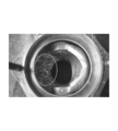
- FIG. 2 is a photographic view showing a state when wear occurs on the inner surface of the valve (X portion in FIG. 2).
- the reason why the local wear occurs is due to an operational characteristic that the valve seat constituting the ball valve body 22 moves at an angle of about 90 degrees when the V ball valve 1 is opened and closed.
- the measurement process for measuring the wear amount of the wear generated on the inner surface of the V ball valve 1 and the wear amount measured in the measurement process in the portion where the wear occurs is measured.
- a welding process for performing build-up welding with a hard welding material is described.
- the amount of wear generated on the inner surface of the V ball valve 1 is measured.
- the amount of wear that has occurred on the inner surface of the valve means the degree of wear that has occurred in the target part to be welded in the next welding process.
- the depth of wear that has occurred on the inner surface of the valve (wear depth) It can be determined by indirectly measuring the volume or wear volume. Note that the measurement of the wear amount is not limited to the measurement based on the wear depth and the wear volume, and may be based on another measure capable of quantitatively measuring the degree of wear.
- the degree of wear that has occurred is estimated by measuring the amount of wear such as the depth of wear and the wear volume on the inner surface of the valve. And based on the measurement result, the tolerance of build-up welding in the next welding process can be determined. According to such a method, it is possible to suppress the reduction of the inner diameter of the valve casing 24, the reduction of the volume based on the reduction, and the reduction of the slurry flow rate, compared with the case where the overlay welding is simply performed as in the prior art. As a result, the performance of the V ball valve 1 having an excellent flow rate control function can be maintained, and the slurry supply control can be executed stably over a long period of time.
- the method for measuring the wear depth and the wear volume is not particularly limited and can be performed by a known method. Specifically, it can be measured using a laser displacement meter or the like, and can be performed by measuring a change in the distance between the lower surface of the displacement meter and the upper surface of the sensing plate of the measuring element.
- the thickness of the valve casing 24 of the dotted circles X1 and X2 in FIG. 1 is about 10 mm to 15 mm. Therefore, when compared with the thickness (thickness at the time of a new article), the wear amount can be measured by measuring the depth of the recess (wear depth) caused by the wear.
- the V ball valve 1 when the V ball valve 1 is continuously used, the occurrence of wear and the degree of wear (amount of wear) are periodically measured by a laser or the like after a predetermined time has elapsed, For example, the measurement result is displayed by display means such as a display.
- the allowable welding amount means an allowable welding amount within a range in which the inner diameter of the valve casing 24 of the V ball valve 1 is not reduced and the internal volume does not decrease.
- welding is performed to the extent that build-up welding is possible in accordance with the measured amount of wear. Therefore, after repair is performed, the valve casing of the valve portion 2 is used. It is possible to prevent a decrease in the volume in 24, a decrease in the slurry flow rate due to this, and a defective rotation of the ball valve body 22.
- the build-up welding is performed using a hard welding material.
- the slurry can be additionally supplied using the V ball valve 1.
- a SUS316 plate made of SUS316 or the like (for example, about 3 mm to 5 mm) is used to apply a patch to the V ball valve made of SUS316 or the like.
- repair by welding with the same material cannot always withstand wear for the same period as a new article because of the effect of changing the structure of the material.
- it is difficult to extend the life by increasing the wear allowance because it is not possible to perform excessive welding that greatly changes the inner diameter of the valve casing.
- the repair frequency is not increased and thereafter for a long period of time.
- the slurry can be added and supplied stably using the V ball valve 1.
- the V ball valve 1 is made of, for example, SUS316
- a hard welding material made of a dissimilar metal that can be welded to the SUS316 is used.
- an austenitic hard chromium / niobium carbide material can be suitably used as the hard welding material.
- An austenitic hard chromium / niobium carbide material has a very hard property compared to a material such as SUS316. The use of other hard welding materials is not limited.
- the build-up welding method is not particularly limited and can be performed by a known method. Specifically, methods such as TIG welding and plasma welding are known, and other methods such as gas welding, plasma welding, and laser welding can also be used. Further, build-up welding is performed according to the amount of wear, and at that time, it may be a single layer or a multilayer layer as long as it is within the allowable welding range. In addition, after performing the build-up welding process, it is hardened by performing a supercooling process or the like.
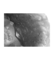
- FIG. 3 is a photographic view of the state of the inner surface of the V ball valve 1 after being subjected to build-up welding with hard welding material against wear generated on the inner surface of the valve.
- the repair method of the V ball valve according to the present embodiment it is possible to effectively extend the period up to the perforation, and to reduce the environmental risk due to leakage of the slurry to the outside. Can be reduced. Moreover, since it can be used stably over a long period of time after the repair, the repair frequency can be reduced, the operation stop period can be shortened, and the risk of process change can be reduced.
- FIG. 2 is a photograph showing the state of wear occurring on the inner surface of the V ball valve before repair, and shows the portion where the X portion is worn. The place where abrasion occurred was in a range of approximately 10 cm ⁇ 10 cm.
- the amount of wear that occurred on the inner surface of the valve was measured. Specifically, the wear depth was measured with a laser displacement meter. As a result, it was found that about 1 mm to 2 mm of wear occurred on the inner surface of the valve casing having a thickness of 10 mm (whole range (10 cm ⁇ 10 cm)).
Landscapes
- Engineering & Computer Science (AREA)
- General Engineering & Computer Science (AREA)
- Mechanical Engineering (AREA)
- Sliding Valves (AREA)
- Taps Or Cocks (AREA)
- Details Of Valves (AREA)
- Valve Housings (AREA)
- Heat Treatment Of Articles (AREA)
Abstract
バルブの性能を維持しながら、局部的に生じた摩耗を効率的に補修して、長期に亘って使用することができるVボールバルブの補修方法を提供する。 本発明に係るVボールバルブの補修方法は、Vボールバルブにおけるバルブ内表面に生じた摩耗を捕集する方法であって、バルブ内表面に生じた摩耗の摩耗量を計測する計測工程と、摩耗が生じている部分において、計測された摩耗量に応じて硬質溶接材により肉盛り溶接を施す溶接工程と、を有する。
Description
本発明は、Vボールバルブの補修方法に関するものであり、スラリーの供給制御により局部的に生じた摩耗を効率的に補修し、長期に亘って使用を継続することができる方法に関するものである。
リモナイトやサプロライト等のニッケル酸化鉱石を、硫酸溶液と共にオートクレーブ等の加圧装置に装入し、240℃~260℃程度の高温高圧下でニッケルを浸出する、「高温加圧酸浸出(HPAL:High Pressure Acid Leach)」と呼ばれる製造プロセスが実用化されている。
高温加圧酸浸出法を用いたプロセスでは、高圧酸浸出で得られた浸出スラリーに遊離硫酸が残留することから、その遊離硫酸を中和する中和処理を行う。具体的に、遊離硫酸の中和に際しては、一般的で安価なカルシウム系の中和剤、例えば、石灰石や消石灰を添加することで処理している。なお、遊離硫酸とは、HPALプロセスで十分な浸出を行うために過剰に加えた硫酸のうちの未反応で残留した硫酸を意味する。
中和剤として用いる石灰石は、一般的に、プロセス液との反応効率を上げるために、ボールミル等の粉砕設備を用いて粒度D50%で8μm~10μm程度のスラリーとされる。そして、中和処理に際して、石灰石スラリーは、プロセス液のpH値に対応するコントロールバルブによってその添加量が調整される。
さて、連続的に変化するpH値によって制御させるコントロールバルブは、その開閉頻度が高く、石灰石スラリーの状態によっては短期間のうちにケーシングの摩耗が発生することがある。多くの場合、そのコントロールバルブとしては、石灰石の耐摩耗性やハンドリングの優位性の観点から、V字状にカットされたボール型コントロールバルブ(以下、単に「Vボールバルブ」ともいう)が用いられる。そして、そのVボールバルブにおいても、開閉頻度や石灰石スラリーの状態によっては短期間(例えば1ヶ月程度)で、ケーシングの一部に局部的な摩耗が生じ、その結果としてケーシングの内側から削られていき、最終的にケーシングを貫通して石灰石スラリーが外部へと噴出してしまう。
このような摩耗は、スラリーの流れ方向が一定であるため、ほぼ同一箇所に限定されているという特徴を有する。一度ケーシングの外へ漏れが発生してしまうと、石灰石スラリーの添加ラインは使用できなくなり、するとプロセス液のpH制御が困難となる。
ここで、Vボールバルブは、バルブ内部に組み込まれている半球状の弁体の開閉度により流量を制御している。より具体的に、このVボールバルブは、エアーを駆動源としてアクチュエータで半球状の弁体の開閉が行われる。また、半球状のボールの開口側がV字状にカットされているため、流量調節にも優れた性能を有している。
一方で、Vボールバルブに摩耗が生じた場合、次のような特徴がある。
(同一箇所に摩耗が発生する)
Vボールバルブの流れ方向は常に一定方向であることから、ケーシングの摩耗はほぼ同一部分において局部的に促進され、最終的にケーシングを貫通して石灰石スラリーがケーシング外部へと噴出してしまう。
(弁体の外部への噴出以外の不具合頻度は低い)
Vボールバルブの不具合のほぼすべては、摩耗が発生することによるケーシング外部への石灰石スラリーの噴出であり、その他の不具合の発生頻度は低い。
(同一箇所に摩耗が発生する)
Vボールバルブの流れ方向は常に一定方向であることから、ケーシングの摩耗はほぼ同一部分において局部的に促進され、最終的にケーシングを貫通して石灰石スラリーがケーシング外部へと噴出してしまう。
(弁体の外部への噴出以外の不具合頻度は低い)
Vボールバルブの不具合のほぼすべては、摩耗が発生することによるケーシング外部への石灰石スラリーの噴出であり、その他の不具合の発生頻度は低い。
このような問題を改善する方法としては、一般に、ガス管や水道管等のパイプラインにできた腐食等の欠陥を補修する場合と同様に、溶接の肉盛り、いわゆるパチ当て等の補修方法や、補修部分の外周に補修用のバンドを被覆する方法等が採用されている(例えば、特許文献1参照。)。しかしながら、溶接の肉盛りやパチ当て等の補修は、応急処置としては有効であるものの、恒久的な補修としては不向きである。
本発明は、このような実情に鑑みて提案されたものであり、バルブの性能を維持しながら、局部的に生じた摩耗を効率的に補修して、長期に亘って使用することができるVボールバルブの補修方法を提供することを目的とする。
本発明者は、上述した課題を解決するために鋭意検討を重ねた。その結果、バルブ内表面に生じた摩耗の摩耗量を計測し、その摩耗が生じている部分において、計測された摩耗量に応じて硬質溶接材により肉盛り溶接を施すことにより、バルブの性能を維持しながら、補修後に長期に亘って使用可能とすることができることを見出し、本発明を完成するに至った。
(1)本発明の第1の発明は、Vボールバルブにおけるバルブ内表面に生じた摩耗を捕集する方法であって、前記バルブ内表面に生じた摩耗の摩耗量を計測する計測工程と、前記摩耗が生じている部分において、計測された前記摩耗量に応じて硬質溶接材により肉盛り溶接を施す溶接工程と、を有する、Vボールバルブの補修方法である。
(2)本発明の第2の発明は、第1の発明において、前記計測工程では、前記摩耗量として摩耗深度又は摩耗体積を計測する、Vボールバルブの補修方法である。
(3)本発明の第3の発明は、第1又は第2の発明において、前記Vボールバルブは、SUS316により構成されており、前記溶接工程では、前記SUS616に対して溶接が可能な硬質溶接材を用いる、Vボールバルブの補修方法である。
(4)本発明の第4の発明は、第3の発明において、前記溶接工程では、前記硬質溶接材としてオーステナイト系硬質クロム/ニオブ炭化物材を用いて肉盛り溶接する、Vボールバルブの補修方法である。
(5)本発明の第1の発明は、第1乃至第4のいずれかの発明において、前記溶接工程では、前記バルブ内表面における局部的な摩耗部分にのみ、前記硬質溶接材で肉盛り溶接する、Vボールバルブの補修方法である。
(6)本発明の第6の発明は、第1乃至第5のいずれかの発明において、前記Vボールバルブは、中和剤としての石灰石スラリーの流量調整に用いられる、Vボールバルブの補修方法である。
本発明によれば、バルブの性能を維持しながら、局部的に生じた摩耗を効率的に補修することができ、長期に亘って使用することができるVボールバルブの補修方法を提供することができる。
以下、本発明の具体的な実施形態(以下、「本実施の形態」という)について詳細に説明する。なお、本発明は以下の実施形態に限定されるものではなく、本発明の要旨を変更しない範囲で種々の変更が可能である。
≪1.Vボールバルブの構成≫
本実施の形態に係るVボールバルブの補修方法は、Vボールバルブにおけるバルブ内表面に生じた摩耗を捕集する方法である。Vボールバルブとは、ボールの開口側がV字状にカットされたボールバルブをいう。以下では、補修方法の詳細な説明に先立ち、このVボールバルブの構成について簡単に説明する。
本実施の形態に係るVボールバルブの補修方法は、Vボールバルブにおけるバルブ内表面に生じた摩耗を捕集する方法である。Vボールバルブとは、ボールの開口側がV字状にカットされたボールバルブをいう。以下では、補修方法の詳細な説明に先立ち、このVボールバルブの構成について簡単に説明する。
図1は、Vボールバルブの要部の構成を示す縦断面図である。Vボールバルブ1は、バルブ部2と、ボール弁体22の開閉を制御するアクチュエータ部3とから構成されている。なお、図1では、主要な構成のみ符号を付して概要を説明する。
バルブ部2は、スラリー等の流体が流れる流路21を有し、その流路21の途中に外形が球状(半球状)のボール弁体22が配置されている。図1において、流路21に沿って明示した矢印Fはスラリー等の流体の流れを示す。以下では、その流体として「スラリー」を具体例として説明を続ける。
バルブ部2を構成する球状のボール弁体22には、流路21とほぼ同径の貫通孔23が設けられている。ボール弁体22が回動して開くことにより、ボール弁体22を構成するバルブシートが約90度の角度で動くことで、スラリーが貫通孔23を通って流路21を流れるようになる(矢印F方向)。また、ボール弁体22は、半球状のボールの開口側がV字状にカットされている(例えば図2参照)。このようにV字状にカットされた開口部を有するボール弁体22であることにより、ボール弁体22の回動によるスラリーの流量調節をより的確に行うことができる。
なお、バルブ部2においては、符号24はバルブボディ本体(バルブケーシング)の構成を示し、符号25はバルブキャップの構成を示す。
アクチュエータ部3には、空圧シリンダー31が設けられている。また、空圧シリンダー31には、回転可能なシャフト32が連結されている。空圧シリンダー31におけるピストンの往復運動によりシャフト32が回転すると、そのシャフト32が回転軸となってバルブ部2におけるボール弁体22の開閉制御が行われる。なお、アクチュエータ部3では、空圧シリンダー31が構成されている態様について説明したが、空圧シリンダー等のシリンダー機構に限られず、電動モータ等により構成されるようにし、モータの駆動によりシャフト32を回動させる態様であってもよい。
ここで、Vボールバルブ1において、その構成材料としては特に限定されないが、例えばオーステナイト系ステンレス鋼を用いて構成することができる。オーステナイト系ステンレス鋼のなかでも、特にSUS316は、耐腐食性に優れており、高い強度も有し、コントロールバルブの構成材料としてより好適である。
≪2.Vボールバルブの補修方法≫
さて、上述したような構成を有するVボールバルブ1は、例えば石灰石や消石灰等の中和剤のスラリーの添加ラインにおけるコントロールバルブとして好適に用いられる。一般的に、中和処理においては、溶液のpH状態が連続的に変化することから、Vボールバルブ1の開閉頻度も非常に多くなる。そして、Vボールバルブ1を用いて添加供給する石灰石スラリー等のスラリーの流速もはやく、またスラリー自体の状態によっては短期間のうちにバルブケーシング24の摩耗が生じる。
さて、上述したような構成を有するVボールバルブ1は、例えば石灰石や消石灰等の中和剤のスラリーの添加ラインにおけるコントロールバルブとして好適に用いられる。一般的に、中和処理においては、溶液のpH状態が連続的に変化することから、Vボールバルブ1の開閉頻度も非常に多くなる。そして、Vボールバルブ1を用いて添加供給する石灰石スラリー等のスラリーの流速もはやく、またスラリー自体の状態によっては短期間のうちにバルブケーシング24の摩耗が生じる。
具体的に、Vボールバルブ1においては、例えば図1中の点線丸囲み部X1,X2等の、バルブケーシング24の内表面(バルブ内表面)に局部的に摩耗が生じる。図2は、バルブ内表面に摩耗が生じたときの様子を示す写真図である(図2中のX部)。このように、局部的に摩耗が生じる理由は、Vボールバルブ1において開閉時にボール弁体22を構成するバルブシートが約90度の角度で動くという動作的な特徴によると考えられる。
従来、Vボールバルブ1のバルブ内表面に局部的な摩耗が生じたときには、その摩耗部分を肉盛り溶接やパチ当て等により補修することが効果的であることが知られている。ところが、肉盛り溶接等による補修は、一時的には改善効果はあるものの、次第に新たな摩耗が生じてその繰返しの補修が必要となり、その度に操業を停止する等の措置を要する。
また、単に肉盛り溶接を施すといっても、その補修効果を長期に亘って持続させるためにVボールバルブ1のバルブケーシング24における内径が小さくなるような肉盛り溶接を行ったのでは、そのバルブケーシング24内の容積(体積空間)が著しく減少し、コントロールすべきスラリーの流量の低下をもたらす。さらに、このような補修では、過剰な肉盛り溶接の箇所が物理的な障害となってボール弁体22の有効な開閉動作の不具合をもたらすことがあり、すると、V字状にカットしたボール弁体22による効果的な流量制御を行うことができなくなる。
そこで、本実施の形態においては、Vボールバルブ1のバルブ内表面に生じた摩耗の摩耗量を計測する計測工程と、摩耗が生じている部分において、計測工程にて計測された摩耗量に応じて硬質溶接材により肉盛り溶接を施す溶接工程と、を有する補修方法を行う。以下、各工程についてそれぞれ説明する。
[計測工程]
計測工程では、Vボールバルブ1のバルブ内表面に生じた摩耗の摩耗量を計測する。バルブ内表面に生じた摩耗量とは、次の溶接工程にて肉盛り溶接を施す対象部位に発生している摩耗の程度をいい、例えば、バルブ内表面に生じた摩耗の深度(摩耗深度)や体積(摩耗体積)により間接的に計測して求めることができる。なお、摩耗量の計測にあたっては、摩耗深度や摩耗体積に基づく計測に限られず、その他摩耗の程度を定量的に計測可能なものに基づいてもよい。
計測工程では、Vボールバルブ1のバルブ内表面に生じた摩耗の摩耗量を計測する。バルブ内表面に生じた摩耗量とは、次の溶接工程にて肉盛り溶接を施す対象部位に発生している摩耗の程度をいい、例えば、バルブ内表面に生じた摩耗の深度(摩耗深度)や体積(摩耗体積)により間接的に計測して求めることができる。なお、摩耗量の計測にあたっては、摩耗深度や摩耗体積に基づく計測に限られず、その他摩耗の程度を定量的に計測可能なものに基づいてもよい。
計測工程では、このようにバルブ内表面における摩耗深度や摩耗体積等の摩耗量を計測することによって、発生した摩耗の程度を推測する。そして、その計測結果に基づいて、次の溶接工程における肉盛り溶接の許容量を決定することができる。このような方法によれば、従来のように単に肉盛り溶接を施す場合と比べて、バルブケーシング24の内径の縮小や、それに基づく容積の減少及びスラリー流量の低下の発生を抑えることができる。これにより、優れた流量制御機能を備えたVボールバルブ1の性能を維持して、長期に亘って安定的にスラリーの供給コントロールを実行することが可能となる。
摩耗深度や摩耗体積の計測方法としては、特に限定されず公知の方法により行うことができる。具体的には、レーザ変位計等を用いて計測することができ、変位計の下面と測定子の感知皿の上面との距離の変化を測定することによって行うことができる。例えば、Vボールバルブ1においては、図1中の点線丸囲み部X1,X2のバルブケーシング24の厚みとしてはおよそ10mm~15mm程度である。したがって、その厚み(新品時の厚み)と比較したとき、その摩耗により生じた凹部の深さ(摩耗深度)等を測定することによって、摩耗量を計測することができる。
なお、この計測工程における処理は、コンピュータによって自動化するようにしてもよい。具体的には、Vボールバルブ1を継続的に使用していくにあたり、所定の時間経過後に定期的にレーザ等により摩耗の発生や、発生した摩耗の程度(摩耗量)を測定するようにし、例えばディスプレイ等の表示手段により計測結果を表示するようにする。
[溶接工程]
溶接工程では、摩耗が生じている部分において、計測工程にて計測された摩耗量に応じて、硬質溶接材により肉盛り溶接を施す。この溶接工程は、肉盛り溶接を施して補修を行う工程であり、このとき本実施の形態においては、計測工程にて計測された摩耗量に基づいて、その摩耗量から許容される溶接量(溶接許容量)を基準として肉盛り溶接する。
溶接工程では、摩耗が生じている部分において、計測工程にて計測された摩耗量に応じて、硬質溶接材により肉盛り溶接を施す。この溶接工程は、肉盛り溶接を施して補修を行う工程であり、このとき本実施の形態においては、計測工程にて計測された摩耗量に基づいて、その摩耗量から許容される溶接量(溶接許容量)を基準として肉盛り溶接する。
溶接許容量とは、Vボールバルブ1のバルブケーシング24の内径が縮小されず、内容積の減少が生じない範囲内での許容される溶接量をいう。このように、本実施の形態に係る補修方法では、計測した摩耗量に応じて肉盛り溶接が可能な分だけ溶接を施すようにしているため、補修を実施した後に、バルブ部2のバルブケーシング24内の容積の減少や、それによるスラリー流量の低下、ボール弁体22の回動不良の発生を防ぐことができる。
ここで、肉盛り溶接に際しては、硬質溶接材を用いて行うことを特徴とする。このように、計測した摩耗量に応じて硬質溶接材により肉盛り溶接を施すことによって、そのバルブ内表面に耐摩耗性を付与する処置を施すことができ、その補修後、長期に亘って安定的にVボールバルブ1を用いてスラリーを添加供給することができる。
従来、例えば穴あき補修等においては、SUS316等により構成されるVボールバルブに対して、同材料のSUS316の板(例えば3mm~5mm程度)を用いて外側からパッチ当てを行い、内部からSUS316の溶接材にて補修を実施していた。しかしながら、同材料による溶接での補修は、その材質の組織が変化する影響から、必ずしも新品同様の期間、摩耗に耐え得るものではない。また、上述したように、バルブケーシングの内径を大きく変えるほどの過剰な溶接を行うことはできないことから摩耗代を増やすことによる寿命延長を図ることも難しかった。
これに対して、硬質溶接材を用いて肉盛り溶接を施す態様によれば、発生した摩耗量に応じた溶接許容量の範囲での溶接によっても、補修頻度を増やすことなく、その後長期間に亘って安定的にVボールバルブ1を使用してスラリーの添加供給を行うことができる。
硬質溶接材としては、Vボールバルブ1が例えばSUS316により構成されていれば、そのSUS316に対して溶接が可能な異種金属からなる硬質溶接材を用いる。具体的に、硬質溶接材としては、例えば、オーステナイト系硬質クロム/ニオブ炭化物材を好適に用いることができる。オーステナイト系硬質クロム/ニオブ炭化物材は、例えばSUS316等の材料と比べて非常に硬い性質を有している。なお、その他の硬質溶接材の使用を制限するものではない。
また、肉盛り溶接の方法としては、特に限定されず公知の方法により行うことができる。具体的には、TIG溶接、プラズマ溶接等の方法が知られており、そのほか、ガス肉盛、プラズマ肉盛、レーザ肉盛等の肉盛溶接方法も利用することができる。また、摩耗量に応じて肉盛り溶接を行うことになるが、そのとき、溶接許容量の範囲内であれば一層盛りであっても多層盛りであってもよい。なお、肉盛り溶接の処理を施した後には、過冷処理等することによって硬化させる。
なお、図3は、Vボールバルブ1のバルブ内表面に生じた摩耗に対して硬質溶接材により肉盛り溶接を施した後の、そのバルブ内表面の様子を観察した写真図である。
以上詳細に説明したように、本実施の形態に係るVボールバルブの補修方法によれば、穴あきに至るまでの期間を効果的に延ばすことができ、スラリーの外部への漏れによる環境リスクを低減させることができる。また、補修後、長期に亘って安定的に使用することができることから、補修頻度を減らすことができ、操業停止期間を短くすることが可能となり、プロセス変化のリスクを低減することができる。
以下、本発明を適用した具体的な実施例について説明するが、本発明はこれらの実施例に何ら限定されるものではない。
[実施例]
石灰石スラリーの添加ラインに使用するVボールバルブ(材質:SUS316)において、継続的な使用により生じたバルブ内表面の摩耗を補修する処理を行った。摩耗対策として、耐摩耗性に優れており弁体母材となるSUS316と溶接肉盛が可能な異種金属の肉盛補修を実施した。なお、図2は、補修を施す前のVボールバルブのバルブ内表面に生じた摩耗の様子を示す写真図であり、X部が摩耗した箇所を示す。摩耗が生じた箇所はおよそ10cm×10cmの範囲であった。
石灰石スラリーの添加ラインに使用するVボールバルブ(材質:SUS316)において、継続的な使用により生じたバルブ内表面の摩耗を補修する処理を行った。摩耗対策として、耐摩耗性に優れており弁体母材となるSUS316と溶接肉盛が可能な異種金属の肉盛補修を実施した。なお、図2は、補修を施す前のVボールバルブのバルブ内表面に生じた摩耗の様子を示す写真図であり、X部が摩耗した箇所を示す。摩耗が生じた箇所はおよそ10cm×10cmの範囲であった。
先ず、バルブ内表面に生じた摩耗の量を計測した。具体的には、レーザ変位計により摩耗深度を測定した。その結果、厚さ10mmのバルブケーシングの内表面(摩耗が生じた全範囲(10cm×10cmの全範囲))に、1mm~2mm程度の摩耗が生じていることが分かった。
次に、計測した摩耗量に基づいて、摩耗が生じている全範囲に、硬質溶接材を用いた肉盛り溶接を施した。具体的に、計測した摩耗量に基づいて、バルブ内表面の摩耗箇所全体に1mm~2mm程度の肉盛り溶接を施した。硬質溶接材としては、オーステナイト系硬質クロム/ニオブ炭化物材(Weldwell社製,ABRASOCORD43)を用いた。なお、バルブ内表面において摩耗が生じていたのは一部分の範囲で局所的であり、摩耗が生じていない箇所には当然に溶接処理を施さなかった。
このような補修を行ったのち、捕集後のVボールバルブを石灰石スラリーの添加ラインに再度取り付け、スラリーの添加供給を行った。その結果、再度局部的な摩耗が生じて穴あきが発生するまで2か月間ほどかかり、長期に亘って使用を継続することができた。また、その間、ボール弁体の回動も効果的に行われ、スラリーの流量調整も的確なものとなり、Vボールバルブの性能を十分に発揮した。
1 Vボールバルブ
2 バルブ部
3 アクチュエータ部
21 流路
22 ボール弁体
23 貫通孔
24 バルブボディ本体(バルブケーシング)
25 バルブキャップ
31 モータ
32 シャフト
2 バルブ部
3 アクチュエータ部
21 流路
22 ボール弁体
23 貫通孔
24 バルブボディ本体(バルブケーシング)
25 バルブキャップ
31 モータ
32 シャフト
Claims (6)
- Vボールバルブにおけるバルブ内表面に生じた摩耗を捕集する方法であって、
前記バルブ内表面に生じた摩耗の摩耗量を計測する計測工程と、
前記摩耗が生じている部分において、計測された前記摩耗量に応じて硬質溶接材により肉盛り溶接を施す溶接工程と、を有する
Vボールバルブの補修方法。 - 前記計測工程では、前記摩耗量として摩耗深度又は摩耗体積を計測する
請求項1に記載のVボールバルブの補修方法。 - 前記Vボールバルブは、SUS316により構成されており、
前記溶接工程では、前記SUS616に対して溶接が可能な硬質溶接材を用いる
請求項1又は2に記載のVボールバルブの補修方法。 - 前記溶接工程では、前記硬質溶接材としてオーステナイト系硬質クロム/ニオブ炭化物材を用いて肉盛り溶接する
請求項3に記載のVボールバルブの補修方法。 - 前記溶接工程では、前記バルブ内表面における局部的な摩耗部分にのみ、前記硬質溶接材で肉盛り溶接する
請求項1乃至4のいずれか1項に記載のVボールバルブの補修方法。 - 前記Vボールバルブは、中和剤としての石灰石スラリーの流量調整に用いられる
請求項1乃至5のいずれか1項に記載のVボールバルブの補修方法。
Priority Applications (1)
| Application Number | Priority Date | Filing Date | Title |
|---|---|---|---|
| PH12019501086A PH12019501086A1 (en) | 2016-11-17 | 2019-05-16 | Method of repairing v ball valve |
Applications Claiming Priority (2)
| Application Number | Priority Date | Filing Date | Title |
|---|---|---|---|
| JP2016224049A JP6327322B2 (ja) | 2016-11-17 | 2016-11-17 | Vボールバルブの補修方法 |
| JP2016-224049 | 2016-11-17 |
Publications (1)
| Publication Number | Publication Date |
|---|---|
| WO2018092487A1 true WO2018092487A1 (ja) | 2018-05-24 |
Family
ID=62146569
Family Applications (1)
| Application Number | Title | Priority Date | Filing Date |
|---|---|---|---|
| PCT/JP2017/037521 Ceased WO2018092487A1 (ja) | 2016-11-17 | 2017-10-17 | Vボールバルブの補修方法 |
Country Status (3)
| Country | Link |
|---|---|
| JP (1) | JP6327322B2 (ja) |
| PH (1) | PH12019501086A1 (ja) |
| WO (1) | WO2018092487A1 (ja) |
Cited By (1)
| Publication number | Priority date | Publication date | Assignee | Title |
|---|---|---|---|---|
| CN114320337A (zh) * | 2021-09-15 | 2022-04-12 | 山东优拓工程装备有限公司 | 隧道挖掘设备用泥石直排装置 |
Citations (3)
| Publication number | Priority date | Publication date | Assignee | Title |
|---|---|---|---|---|
| JPS62233307A (ja) * | 1986-03-31 | 1987-10-13 | 芝浦メカトロニクス株式会社 | レ−ル形状の修正方法および装置 |
| JPH01172683A (ja) * | 1987-12-25 | 1989-07-07 | Kubota Ltd | 弁のシート部 |
| JP2004077408A (ja) * | 2002-08-22 | 2004-03-11 | Hitachi Ltd | 軽水原子炉用弁 |
-
2016
- 2016-11-17 JP JP2016224049A patent/JP6327322B2/ja active Active
-
2017
- 2017-10-17 WO PCT/JP2017/037521 patent/WO2018092487A1/ja not_active Ceased
-
2019
- 2019-05-16 PH PH12019501086A patent/PH12019501086A1/en unknown
Patent Citations (3)
| Publication number | Priority date | Publication date | Assignee | Title |
|---|---|---|---|---|
| JPS62233307A (ja) * | 1986-03-31 | 1987-10-13 | 芝浦メカトロニクス株式会社 | レ−ル形状の修正方法および装置 |
| JPH01172683A (ja) * | 1987-12-25 | 1989-07-07 | Kubota Ltd | 弁のシート部 |
| JP2004077408A (ja) * | 2002-08-22 | 2004-03-11 | Hitachi Ltd | 軽水原子炉用弁 |
Cited By (1)
| Publication number | Priority date | Publication date | Assignee | Title |
|---|---|---|---|---|
| CN114320337A (zh) * | 2021-09-15 | 2022-04-12 | 山东优拓工程装备有限公司 | 隧道挖掘设备用泥石直排装置 |
Also Published As
| Publication number | Publication date |
|---|---|
| JP2018080774A (ja) | 2018-05-24 |
| JP6327322B2 (ja) | 2018-05-23 |
| PH12019501086A1 (en) | 2019-12-11 |
Similar Documents
| Publication | Publication Date | Title |
|---|---|---|
| US10837562B2 (en) | Ball valves with lattice structures and methods of manufacture | |
| CN105817832B (zh) | 压力容器现场修复与再制造工艺 | |
| CN101862884B (zh) | 一种连续管的管-管现场对接焊方法 | |
| US20120312410A1 (en) | Flexible pipe connected with flexible pipe connecting structure and method of connecting flexible pipe connecting structure with flexible pipe | |
| JP4838796B2 (ja) | 密封外側表面を有する流体バルブ制御部材 | |
| CN103350320B (zh) | 一种耐腐蚀双金属复合管的生产方法 | |
| CN103203420B (zh) | 一种换热管与管板及防冲套管胀接方法 | |
| JP6327322B2 (ja) | Vボールバルブの補修方法 | |
| Meng et al. | Investigation on creep behavior of welded joint of advanced 9% Cr steels | |
| CN101628354B (zh) | 换热器中换热管与管板的内孔焊接方法 | |
| JP6449664B2 (ja) | シール装置 | |
| EP2536951B1 (en) | Compressor casing assembly and manufacturing method thereof | |
| CN104633167A (zh) | 一种大口径全焊接球阀 | |
| CN204893199U (zh) | 一种整体复合法兰 | |
| CN104154264A (zh) | 一种安全双密封球阀 | |
| CN203906833U (zh) | 一种用于气体管道的偏心蝶阀 | |
| CN101818815A (zh) | 多维球密封蝶阀 | |
| CN204328035U (zh) | 一种金属硬密封耐磨浮动球阀 | |
| CN223782354U (zh) | 弯头装置及连续油管 | |
| CN109695774B (zh) | 一种硬密封球阀内漏闭环检修方法 | |
| CN213839617U (zh) | 一种平行双闸板闸阀 | |
| JP5309635B2 (ja) | ガス配管の補修方法 | |
| Li et al. | Study on structure and electrochemical properties of CO (2) corrosion scales on P 110 steel corroded at high temperature and pressure. | |
| JP2007154929A (ja) | ベローズ弁 | |
| JP2017207156A (ja) | アングル弁 |
Legal Events
| Date | Code | Title | Description |
|---|---|---|---|
| 121 | Ep: the epo has been informed by wipo that ep was designated in this application |
Ref document number: 17871298 Country of ref document: EP Kind code of ref document: A1 |
|
| NENP | Non-entry into the national phase |
Ref country code: DE |
|
| 122 | Ep: pct application non-entry in european phase |
Ref document number: 17871298 Country of ref document: EP Kind code of ref document: A1 |