WO2018090158A1 - Extending/retracting suspension apparatus which may be movably mounted on floor of building roof - Google Patents
Extending/retracting suspension apparatus which may be movably mounted on floor of building roof Download PDFInfo
- Publication number
- WO2018090158A1 WO2018090158A1 PCT/CN2016/000638 CN2016000638W WO2018090158A1 WO 2018090158 A1 WO2018090158 A1 WO 2018090158A1 CN 2016000638 W CN2016000638 W CN 2016000638W WO 2018090158 A1 WO2018090158 A1 WO 2018090158A1
- Authority
- WO
- WIPO (PCT)
- Prior art keywords
- floor
- boom
- building
- frames
- hoisting
- Prior art date
Links
Images


Classifications
-
- B—PERFORMING OPERATIONS; TRANSPORTING
- B66—HOISTING; LIFTING; HAULING
- B66D—CAPSTANS; WINCHES; TACKLES, e.g. PULLEY BLOCKS; HOISTS
- B66D3/00—Portable or mobile lifting or hauling appliances
- B66D3/18—Power-operated hoists
-
- B—PERFORMING OPERATIONS; TRANSPORTING
- B66—HOISTING; LIFTING; HAULING
- B66D—CAPSTANS; WINCHES; TACKLES, e.g. PULLEY BLOCKS; HOISTS
- B66D3/00—Portable or mobile lifting or hauling appliances
- B66D3/18—Power-operated hoists
- B66D3/26—Other details, e.g. housings
Definitions
- the invention relates to a hanging device installed on the roof of a building, in particular to a lifting and unloading device which is movably mounted on the floor of a building.
- the external walls of buildings such as houses or buildings are mostly made of cement, brick, metal, non-metal, glass, etc. Due to the long-term exposure to ambient air, dust and sun and rain, they are required to be regularly Carry out maintenance work such as cleaning and repair to ensure the cleanliness and weather resistance of the external walls of the building.
- the maintenance work such as cleaning and repairing of the external wall of the building is mostly carried out by using the hanging device installed on the roof of the building, and vertically lifting and lowering the outer wall of each floor with a cable suspension maintenance platform or a wall washer.
- the maintenance platform can be used by the wall washer or maintenance personnel to facilitate the cleaning or repair work of the external wall; and the wall washer can perform the roller washing operation on the wall by the attached automatic brush wheel.
- the above-mentioned hanging device mounted on the roof can also be used to hang the cable to the ground, and then the heavy object is hung to the window of the desired floor to facilitate the handling of the heavy objects.
- the hanging device needs to be transported to the roof of the building and depends on the daughter wall extending from the roof floor for support, and can be moved horizontally on the roof floor to facilitate the transformation of the suspended object (for example)
- the maintenance platform, wall washer or other heavy objects are in the horizontal position of the outer wall, so the hanging device is generally made into a movable type; however, although the hanging device technology that has been disclosed so far can be changed However, it is not conducive to the exhibition, and even the process of using the vehicle to carry and using the limited elevator space to carry to the roof of the building is all hard and difficult.
- Taiwan Patent Publication No. M444373 and the M507929 case respectively disclose a hanging structure exhibiting an L-shaped frame, and are generally provided with a vertical stand on a movable stage, and the vertical stand is provided by the stand A horizontal bracket with a length that can be stretched and erected is assembled.
- the L-shaped frame of these hanging structures are all locked by screws, etc., which are bulky and are not suitable for disassembly and handling; and their horizontal brackets can be stretched and limited only to control cables, water pipes and wires to extend to the daughter. The distance outside the wall is not helpful for reducing the volume of the hanging structure during the above-mentioned vehicle handling and stair transportation.
- the present invention particularly adopts a triangular positioning form to design a hanging device, and applies a hanger in a form of a spread to improve the problem that the hanging device is disadvantageous for vehicle handling and stair transportation.
- a preferred embodiment of the present invention provides a display-type hanging device that is movably mounted on a floor of a building, comprising: a load box that can be moved and placed on the floor of the building, the load a power cable reel for retracting the cable is arranged in the box, a parapet wall is formed on the top of the building; a boom is formed by a plurality of display frames, and at least one pulley is pivoted at one end of the arm; The plurality of frames can extend to each other, and the boom is obliquely bridged between the load box and the parapet, and the triangular arm and the parapetal wall are constructed as a triangular support.
- the cable on the power reel is suspended by the traction of the extended boom and the support of the pulley, and a heavy object is suspended and suspended from the parapet wall; and the plurality of frames can be combined with each other to form a boom.
- the length of the handling, the length of the carrying arm and the height of the carrying case are both less than the height of an elevator in the building.
- the present invention contemplates a variety of implementations, and the above apparatus also includes the following implementation details:
- the load box comprises a pipe tray for carrying a water discharge pipe, and the water tank is attached with a water tank, and the water pipe on the pipe tray is connected to the water tank.
- the pipe can collect and release the water pipe so that the water pipe can be suspended by the traction of the extension boom and the guide of the pulley Maintain water supply to the maintenance platform or wall washer to clean the exterior wall.
- the load box may further comprise a reel for carrying a discharge line, the reel can collect and release the electric wire, and the electric wire can be suspended to the maintenance platform via the traction of the extension boom and the guide of the pulley Or the wall washer supplies power.
- the plurality of frames are respectively provided with bolt holes, and the plurality of frames can be sleeved with a pin when the plurality of frames are stretched to each other, so that the plurality of frames can be stretched to a desired inclined length to be
- the pin is fixed to prevent loosening and slipping, and it is convenient to remove the pin and fold the boom.
- the boom and the load box are connected via a pullable shaft bolt. In this way, the convenience of disassembly and assembly between the boom and the load box can be improved.
- the present invention also provides another preferred embodiment that is not constrained by the daughter wall, which differs from the above embodiment in that at least one is utilized.
- a bracket is used to replace the parapet, the boom is obliquely connected between the load box and the support frame, and the extended boom, the roof floor and the support frame are constructed as a triangular support structure;
- the support frame has a support frame length standing on the roof floor, and the support frame length is smaller than the elevator car height of the building.
- the extended boom and the support frame may be pivotally connected to each other.
- One end of the support frame is pivotally provided with a swing seat, and the extended boom and the swing seat are coupled to each other.
- the number of the support frames may be two, and at least one of the plurality of frames is provided with a catching seat via the two sides of the engaging seat and the two supporting frames The swing seats are coupled to each other.
- the technical effect of the present invention is to adopt a triangular positioning form, including between the extending boom, the roof floor and the parapet wall, or between the extended boom, the roof floor and the support frame.
- the utility model is constructed as a triangular support structure, which ensures the rigidity of the support structure when the hanging device is suspended, and simplifies the complexity of the hanging structure, and is also advantageous for the staff to stretch and assemble and fold.
- the transportable length of the hanger that can be received by the present invention the height of the load box, and the length of the support frame are smaller than the height of the elevator between the buildings, it is easier to enter and exit the elevator car, which is also advantageous for vehicle handling.
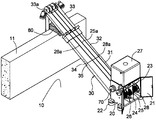
- Figure 1 is a perspective view of a first preferred embodiment of the present invention
- Figure 2 is a front elevational view of Figure 1;
- Figure 3 is a plan view showing the additional tie rod in the embodiment shown in Figure 1;
- Figure 4 is a schematic view of the embodiment shown in Figure 1 folded and placed in the elevator;
- Figure 5 is a perspective view of a second preferred embodiment of the present invention.
- Figure 6 is a front elevational view of Figure 5;
- Figure 7 is a schematic view of the embodiment of Figure 5 folded and placed in the elevator car.
- FIG. 1 and FIG. 2 together to disclose a first preferred embodiment of the present invention, illustrating the display type hanging device, which is installed between the roof 10 of a building and the parapet 11 of a building.
- a load box 20 and a boom 30 are provided.
- the parapet wall 11 is generally formed around the roof 10 of the building and is used as a side wall of the exterior wall of the building which is connected to the roof 10 of the building. among them:
- the load box 20 can be made of a metal case with a receiving space; the side of the load box 20 is provided with a box door 21 for opening and closing the accommodating space in the box; the bottom of the load box 20 is provided with a plurality of corners.
- the wheel 22 is a commercially available product, which is composed of a rubber or metal foot pad combined with a retractable wheel body; when the load carrying case 20 is required to be moved, the wheel body in the foot pad can be released to contact the ground. Eli moves the load box 20 to the position where it is to be installed on the roof floor 10; when the fixed load box 20 is required, it is only necessary to retract the wheel body so that the foot pad contacts the floor top 10, so that The load box 20 is securely placed at a desired location on the roof floor 10.
- the inner or double outer wall of the load box 20 may be attached with a weight 70 such as a weight or a discus as needed to increase the stability of the load box 20 when it is placed on the floor 10 of the building, so as to utilize
- the load box 20 is used as a foundation pile when the boom 30 is placed on the floor 10 of the building.
- the control unit 23 can be disposed in the accommodating space of the load box 20, and the motor 24 and a power reel 25 for accommodating the cable 25a are disposed.
- the control unit 23 controls the forward and reverse rotation of the motor 24 and its rotational speed, and drives the power reel 25 to rotate via the connection of the belt or the chain to release and retract the cable 25a for hanging the heavy object.
- the boom 30 is formed by a plurality of stretchable frames 31, 32, 33 interspersed with each other, and the plurality of frames can be divided into a large frame 31, a middle frame 32 and a small frame 33, which can be made into a hollow rectangle.
- the frame shape and the stretching and retracting operations can be performed by the mutual wearing of the sleeves, so that the operator can easily change the total length of the boom 30.
- the engaging ends of the frames 31, 32, 33 are sleeved with a plurality of bolt holes 34; when the frames 31, 32, 33 are extended to change the required length of the boom 30, the phases can be aligned. Inserting the bolt holes 34 between the two frames, and respectively inserting a bolt 35, thereby fixing the extended frames 31, 32, 33 to prevent the frames 30 from sliding between the frames when the boom 30 is under load, and Easy The operator removes the pin 35 to close the boom.
- a distal end of the large frame 31 of the boom 30 is provided with a pivot hole 36, and the pivot of the boom 30 can be worn by a pullable shaft bolt 37 at a position near the bottom of the front end of the load box 20.
- the connecting hole 36 is connected to the load carrying box 20, and the hanging arm 30 is pivotally connected to the tilting mounting angle via the pivotal connection of the pivoting bolt 37 to the pivoting hole 36; Further, after the plurality of frames 31, 32, 33 extend to each other to obtain the required extension length of the boom 30, the boom 30 can be obliquely bridged between the load box 20 and the parapet 11 Between the extended boom 30, the roof floor 10 and the parapet 11 is constructed as a triangular support structure A (Fig.
- the triangular support structure A can assume a right triangle.
- the connection between the boom 30 and the load box 20 by the extractable shaft bolt 37 helps to improve the convenience of disassembly and assembly between the boom 30 and the load box 20.
- a predetermined position at which the boom 30 (small frame 33) and the top of the parapet 11 are in contact with each other can be placed with a cushion 80 to prevent the boom 30 from rubbing against each other or causing damage to the parapet 11 after being loaded.
- the triangular support structure A can fully disperse the stress under the load state of the weight 30 of the boom 30 to avoid stress concentration between the components of the device.
- the load box 20 when the weight W hoisted by the boom 30 is a wall washer or a maintenance platform for the wall washer to stand, the load box 20 further includes a tray 26 for carrying a drain pipe 26a therein, and The load box 20 may further include a water tank 27 attached to the top thereof, and the water pipe 26a on the pipe tray 26 is connected to the water tank 27 to facilitate the traction of the water pipe 26a via the extended boom 30 and the support of the pulley 33a. It is suspended from the parapet 11 and hangs down to the wall washer or maintenance platform to supply water for wall washing.
- the load box 20 may further include a reel 28 for carrying a discharge line 28a, so that the wire 28a can be stretched.
- the traction of the rear boom 30 and the guiding of the pulley 33a are suspended outside the parapet 11 and descend to the wall washer or the maintenance platform, supply the power of the wall washer, or supply the staff standing on the maintenance platform. The power required to operate the power tool.
- the two pull rods 38a, 38b of the swingable transfer can be respectively pivotally connected to the double sides of the large frame 31 by using the shaft bolts, and the double pull rods 38a, 38b are double.
- a plurality of buckle grooves 39 are formed at equal intervals, wherein one of the pull rods 38a is fastened to the buckle 20a of the end wall of the load box 20 by the buckle groove 39, and the other tie rod 38b is fastened by the buckle groove 39.
- a foot pad 29 allows the foot pad 29 to abut against the end corner of the parapetal wall 11 and the floor top 10, which is implemented to enhance the load intensity of the triangular support structure A and to produce a better stress dispersion effect.
- the total height h1 (which may include a water tank) of the load box 20 may be designed to be smaller than the height of the elevator of the building without affecting the load and support function of the movable load box 20.
- H and since the plurality of frames 31, 32, 33 are made in a form that is convenient to be spread (including the two tie rods 38a, 38b pivoted on the large frame 31), when the booms 30 are folded together
- the boom handling length h2 can also be easily designed to be smaller than the height H of the elevator car, so that the constructor can use the elevator car to carry the hanging device of the present invention, and the implementation can also facilitate the hanging device of the present invention when being transported by the vehicle. Save space on the vehicle.
- FIG. 5 to FIG. 7 disclose a second preferred embodiment of the present invention, which is specifically designed to avoid the load on the parapet 11 of the existing building roof, and the foregoing FIG. 1 to
- the embodiment disclosed in FIG. 4 differs in that the hoisting device is not restrained by the parapet 11 and the at least one support frame 40 is used in place of the parapet 11 to tilt the extended sling 30.
- the utility model is connected between the load box 20 and the support frame 40, and forms a triangular support structure B between the extended boom 30, the roof floor 10 and the support frame 40.
- the support frame has a support frame length h3 standing on the floor of the building, and the support frame length h3 is smaller than the elevator room height H of the building, so as to facilitate the above-mentioned ladder transportation and vehicle handling.
- the number of the support frames 40 can be two, and one end of the two support frames 40 can be pivotally provided with a swinging seat 50 respectively, and the swinging seat 50 provides a flat seating surface 51.
- a plurality of protrusions 52 are formed on the two sides of the 51, and a frame 60 is disposed on the frame 32 of the boom 30.
- the two sides of the frame 60 are respectively formed corresponding to the plurality of protrusions 52.
- There is a column hole 61 so that the arm 30 and the swing seat 50 can be integrally joined to each other by the protrusion of the boss 52 and the column hole 61; thus, the extended boom 30 can be
- the support frames 40 are formed to be pivotally connected to each other to adjust the mounting angle.
- the other end of the support frame 40 can be pivotally connected to the commercially available angle wheel 22 via a pivot pin 22a, so that the support frame 40 can be stably set up against the daughter by the foot pad of the angle wheel 22 At the end corner where the wall 11 meets the roof floor 10, or by means of the wheel body of the angle wheel 22, the adjustment position is moved on the roof floor 10.
- the two pull rods 38a and 38b respectively pivoted on both sides of the large frame 31 are in the present embodiment. It can also be connected between the boom 30 (large frame 31) and the load box 20 by the mutual fastening of the buckle groove and the buckle, and is connected between the boom 30 (the large frame 31) and the support frame 40. In order to strengthen the load intensity of the above triangular support structure B, resulting in better stress dispersion effect.
Abstract
Provided is an extending/retracting suspension apparatus which may be movably mounted on floor of building roof, comprising a load-carrying box (20) which may be moved and placed on the floor of a roof (10); the roof floor (10) has a parapet wall (11) formed thereon; a suspension arm (30) is formed by telescoping a plurality of extending/retracting frames (31, 32, 33); said plurality of frames (31, 32, 33) extend with each other, causing the suspension arm (30) to span at an incline between the load-carrying box (20) and the parapet wall (11), and causing the a triangular support frame to be constructed between the extended suspension arm (30), the roof floor (10), and the parapet wall (11); the plurality of frames (31, 32, 33) may be collapsed together to form a suspension arm (30) transport length; said suspension arm (30) transport length and the height of the load-carrying box (20) both are smaller than the height of an elevator room of the building; thus the invention solves the problems of conventional suspension apparatuses or structures being unfavorable to extension and retraction and of vehicular transport and elevator room transport being difficult.
Description
本发明涉及建筑物楼顶所安装的吊挂器械,特别有关一种可移动装设于建筑物楼顶地面的展收式吊挂装置。The invention relates to a hanging device installed on the roof of a building, in particular to a lifting and unloading device which is movably mounted on the floor of a building.
一般房舍或大楼等建筑物的外墙,大都是由水泥、砖瓦、金属、非金属、玻璃等构筑而成,因长时间遭受环境空气、尘垢及日晒雨淋的影响,都需定期实施清洗、修缮等维护工作,以确保建筑物外墙的洁净度及耐候性。The external walls of buildings such as houses or buildings are mostly made of cement, brick, metal, non-metal, glass, etc. Due to the long-term exposure to ambient air, dust and sun and rain, they are required to be regularly Carry out maintenance work such as cleaning and repair to ensure the cleanliness and weather resistance of the external walls of the building.
已知,目前建筑物外墙的清洗、修缮等维护作业,多半利用建筑物楼顶所安装的吊挂装置,以缆绳悬吊维修平台或洗墙机等垂直升降于各楼层的外墙间。其中,维修平台可供洗墙工人或维修人员站立,以便于实施外墙的清洗或修缮的工作;而洗墙机则可凭借其附设的自动刷轮对墙面进行滚洗作业。此外,又例如建筑物各楼层之间,也可利用上述安装于楼顶的吊挂装置垂降缆绳至地面,而后吊挂重物至所需楼层的窗孔,以利重物的搬运。It is known that the maintenance work such as cleaning and repairing of the external wall of the building is mostly carried out by using the hanging device installed on the roof of the building, and vertically lifting and lowering the outer wall of each floor with a cable suspension maintenance platform or a wall washer. Among them, the maintenance platform can be used by the wall washer or maintenance personnel to facilitate the cleaning or repair work of the external wall; and the wall washer can perform the roller washing operation on the wall by the attached automatic brush wheel. In addition, for example, between the floors of the building, the above-mentioned hanging device mounted on the roof can also be used to hang the cable to the ground, and then the heavy object is hung to the window of the desired floor to facilitate the handling of the heavy objects.
且知,由于吊挂装置都需被搬运至建筑物的楼顶,并依赖楼顶地面所延伸的女儿墙作撑持,而且可在楼顶地面上水平移动,以利于变换被吊挂物(例如维修平台、洗墙机或其它重物等)于外墙的水平位置,因此吊挂装置一般都制成可推移型式;但是,以目前已见公开的吊挂装置技术而言,其虽可推移,但却不利于展收,乃至于包括在利用车载搬运上,以及利用建筑物有限的电梯空间载运至楼顶的过程,都百般艰辛,且窒碍难行。It is also known that the hanging device needs to be transported to the roof of the building and depends on the daughter wall extending from the roof floor for support, and can be moved horizontally on the roof floor to facilitate the transformation of the suspended object (for example) The maintenance platform, wall washer or other heavy objects are in the horizontal position of the outer wall, so the hanging device is generally made into a movable type; however, although the hanging device technology that has been disclosed so far can be changed However, it is not conducive to the exhibition, and even the process of using the vehicle to carry and using the limited elevator space to carry to the roof of the building is all hard and difficult.
例如中国台湾专利公告第M444373案及第M507929案,分别揭示出呈现L型架体的吊挂结构,且概略上都是由一可移动式载台上设置垂立支架,并由该垂立支架上架设可展缩长度的水平支架组构而成。这些吊挂结构的L型架体均属利用螺丝等锁固的型式,体积大,并不利于拆卸及搬运;且其水平支架可展缩的作用,仅限于控制缆绳、水管及电线伸展至女儿墙外的距离,对于缩减吊挂结构于上述车载搬运及梯间搬运时的体积,并无助意。
For example, the Taiwan Patent Publication No. M444373 and the M507929 case respectively disclose a hanging structure exhibiting an L-shaped frame, and are generally provided with a vertical stand on a movable stage, and the vertical stand is provided by the stand A horizontal bracket with a length that can be stretched and erected is assembled. The L-shaped frame of these hanging structures are all locked by screws, etc., which are bulky and are not suitable for disassembly and handling; and their horizontal brackets can be stretched and limited only to control cables, water pipes and wires to extend to the daughter. The distance outside the wall is not helpful for reducing the volume of the hanging structure during the above-mentioned vehicle handling and stair transportation.
发明内容Summary of the invention
有鉴于此,本发明的目的,旨在改善传统吊挂装置或结构并不利于展收,乃至于难以车载搬运及梯间搬运的问题。In view of the above, it is an object of the present invention to improve the conventional hanging device or structure that is not conducive to the spread, and is therefore difficult to carry and handle between the vehicle.
为了实现上述目的并解决问题,本发明特别采用三角定位形式来设计吊挂装置,并且应用可展收形式的吊架来改善吊挂装置不利于车载搬运及梯间搬运的问题。In order to achieve the above object and solve the problem, the present invention particularly adopts a triangular positioning form to design a hanging device, and applies a hanger in a form of a spread to improve the problem that the hanging device is disadvantageous for vehicle handling and stair transportation.
为此,本发明的一较佳实施例,提供一种可移动装设于建筑物楼顶地面的展收式吊挂装置,包括:一载重箱,能移动摆放于楼顶地面,该载重箱内载一收放缆绳用的动力线盘,该楼顶地面形成有一女儿墙;一吊臂,由多个展收式的框架穿套而成,该吊臂一端枢设至少一滑轮;其中,所述多个框架能相互伸展,而使该吊臂斜倾式的跨接于该载重箱与女儿墙之间,且令该伸展的吊臂、楼顶地面与女儿墙之间构筑成一三角形支撑架构,该动力线盘上的缆绳经由该伸展的吊臂的牵引及滑轮的导持而悬持于女儿墙外吊挂一重物垂直升降;且所述多个框架并能相互收合成一吊臂搬运长度,该吊臂搬运长度及该载重箱高度都小于该建筑物的一电梯间高度。To this end, a preferred embodiment of the present invention provides a display-type hanging device that is movably mounted on a floor of a building, comprising: a load box that can be moved and placed on the floor of the building, the load a power cable reel for retracting the cable is arranged in the box, a parapet wall is formed on the top of the building; a boom is formed by a plurality of display frames, and at least one pulley is pivoted at one end of the arm; The plurality of frames can extend to each other, and the boom is obliquely bridged between the load box and the parapet, and the triangular arm and the parapetal wall are constructed as a triangular support. The cable on the power reel is suspended by the traction of the extended boom and the support of the pulley, and a heavy object is suspended and suspended from the parapet wall; and the plurality of frames can be combined with each other to form a boom. The length of the handling, the length of the carrying arm and the height of the carrying case are both less than the height of an elevator in the building.
本发明考量实施上的多样性,上述装置还包含下列实施细节:The present invention contemplates a variety of implementations, and the above apparatus also includes the following implementation details:
其中,该载重箱包含内载一收放水管用的管盘,且该载重箱附设有一水箱,该管盘上的水管并连接该水箱。当接受吊挂的重物是一专供洗墙人员站立的维修平台或洗墙机时,该管盘可收集及释放水管,使水管能经由该伸展吊臂的牵引及滑轮的导持而悬持至该维修平台或洗墙机供应水源,用以清洗外墙。Wherein, the load box comprises a pipe tray for carrying a water discharge pipe, and the water tank is attached with a water tank, and the water pipe on the pipe tray is connected to the water tank. When the weight to be hanged is a maintenance platform or wall washer specially designed for the wall-washing personnel to stand, the pipe can collect and release the water pipe so that the water pipe can be suspended by the traction of the extension boom and the guide of the pulley Maintain water supply to the maintenance platform or wall washer to clean the exterior wall.
其中,该载重箱还可包含内载一收放电线用的线盘,该线盘可收集及释放电线,使电线能经由该伸展吊臂的牵引及滑轮的导持而悬持至该维修平台或洗墙机供应电源。Wherein, the load box may further comprise a reel for carrying a discharge line, the reel can collect and release the electric wire, and the electric wire can be suspended to the maintenance platform via the traction of the extension boom and the guide of the pulley Or the wall washer supplies power.
其中,所述多个框架上分别设有栓孔,所述多个框架于相互伸展时能对位栓孔穿套一销栓,以便于多个框架伸展至所需斜倾长度的后能被销栓固定而防止松动滑脱,并且便于卸除销栓而收合吊臂。Wherein, the plurality of frames are respectively provided with bolt holes, and the plurality of frames can be sleeved with a pin when the plurality of frames are stretched to each other, so that the plurality of frames can be stretched to a desired inclined length to be The pin is fixed to prevent loosening and slipping, and it is convenient to remove the pin and fold the boom.
其中,该吊臂与载重箱之间经由一可抽拔式的轴栓连接。如此实施,能提升吊臂与载重箱之间于拆卸及组装时的便捷性。Wherein, the boom and the load box are connected via a pullable shaft bolt. In this way, the convenience of disassembly and assembly between the boom and the load box can be improved.
此外,为了避免对现有建筑物楼顶的女儿墙造成负荷,本发明还提供另一不受女儿墙拘束的较佳实施例,其与上述实施例不同的处在于:利用至少一支
撑架来取代女儿墙,该吊臂是斜倾式的跨接于该载重箱与该支撑架之间,且令该伸展的吊臂、楼顶地面与支撑架之间构筑成一三角形支撑架构;其中,该支撑架具有一立置于楼顶地面的支撑架长度,该支撑架长度小于该建筑物的电梯间高度。In addition, in order to avoid burdening the parapet wall of the existing building roof, the present invention also provides another preferred embodiment that is not constrained by the daughter wall, which differs from the above embodiment in that at least one is utilized.
a bracket is used to replace the parapet, the boom is obliquely connected between the load box and the support frame, and the extended boom, the roof floor and the support frame are constructed as a triangular support structure; Wherein, the support frame has a support frame length standing on the roof floor, and the support frame length is smaller than the elevator car height of the building.
在进一步实施细节中,该伸展的吊臂与该支撑架之间可以是相互枢接。其中,该支撑架一端枢设有一摆动座,该伸展的吊臂与该摆动座之间相互嵌接结合。而且,该支撑架的数量可为二,所述多个框架中的至少一框架上配置有一嵌接座,该伸展的吊臂经由该嵌接座的双侧而与所述二支撑架上的摆动座相互嵌接结合。In further implementation details, the extended boom and the support frame may be pivotally connected to each other. One end of the support frame is pivotally provided with a swing seat, and the extended boom and the swing seat are coupled to each other. Moreover, the number of the support frames may be two, and at least one of the plurality of frames is provided with a catching seat via the two sides of the engaging seat and the two supporting frames The swing seats are coupled to each other.
依据上述实施内容,本发明的技术效果在于:采用三角定位形式,包括令伸展的吊臂、楼顶地面与女儿墙之间,或者是令该伸展的吊臂、楼顶地面与支撑架之间,构筑成一三角形支撑架构,可确保吊挂装置于悬挂重物时该支撑架构的刚性强度,并可简化吊挂结构的复杂度,而且还利于工作人员伸展组装及收合搬运。进一步的说,由于本发明可收的吊架于收合后的搬运长度、载重箱高度及支撑架长度都小于建筑物的电梯间高度,因此较容易进、出电梯间,也利于车载搬运。According to the above implementation, the technical effect of the present invention is to adopt a triangular positioning form, including between the extending boom, the roof floor and the parapet wall, or between the extended boom, the roof floor and the support frame. The utility model is constructed as a triangular support structure, which ensures the rigidity of the support structure when the hanging device is suspended, and simplifies the complexity of the hanging structure, and is also advantageous for the staff to stretch and assemble and fold. Furthermore, since the transportable length of the hanger that can be received by the present invention, the height of the load box, and the length of the support frame are smaller than the height of the elevator between the buildings, it is easier to enter and exit the elevator car, which is also advantageous for vehicle handling.
在此所揭示的各实施例的特征及技术效果,将呈现于下方的描述与图示中。The features and technical effects of the various embodiments disclosed herein will be presented in the description and drawings below.
图1是本发明第一款较佳实施例的立体配置图;Figure 1 is a perspective view of a first preferred embodiment of the present invention;
图2是图1的正视图;Figure 2 is a front elevational view of Figure 1;
图3是图1所示实施中附加拉杆的平面示意图;Figure 3 is a plan view showing the additional tie rod in the embodiment shown in Figure 1;
图4是图1所示实施例收合暨摆置于电梯间内的示意图;Figure 4 is a schematic view of the embodiment shown in Figure 1 folded and placed in the elevator;
图5是本发明第二款较佳实施例的立体配置图;Figure 5 is a perspective view of a second preferred embodiment of the present invention;
图6是图5的正视图;Figure 6 is a front elevational view of Figure 5;
图7是图5所示实施例收合暨摆置于电梯间内的示意图。Figure 7 is a schematic view of the embodiment of Figure 5 folded and placed in the elevator car.
附图标记说明:10楼顶地面;11女儿墙;20载重箱;20a扣杆;21箱门;22角轮;22a轴栓;23控制单元;24马达;25动力线盘;25a缆绳;26管盘;26a水管;27水箱;28线盘;28a电线;29脚垫;30吊臂;31、32、33框架;
33a滑轮;34栓孔;35销栓;36枢接孔;37轴栓;38a、38b拉杆;39扣槽;40支撑架;50摆动座;51座面;52凸柱;60嵌接座;61柱孔;70配重块;80软垫;A、B三角形支撑架构;H电梯间高度;h1载重箱总高度;h2吊臂搬运长度;h3支撑架长度;W重物。DESCRIPTION OF REFERENCE NUMERALS: 10th floor top floor; 11 daughter wall; 20 load box; 20a buckle; 21 box door; 22 angle wheel; 22a shaft bolt; 23 control unit; 24 motor; 25 power reel; 25a cable; Pipe plate; 26a water pipe; 27 water tank; 28 wire plate; 28a wire; 29 foot pad; 30 boom; 31, 32, 33 frame;
33a pulley; 34 bolt hole; 35 bolt; 36 pivot hole; 37 shaft bolt; 38a, 38b tie rod; 39 buckle groove; 40 support frame; 50 swing seat; 51 seat surface; 52 boss; 60 engagement seat; 61 column hole; 70 weight block; 80 cushion; A, B triangle support structure; H elevator height; h1 total height of the load box; h2 boom handling length; h3 support frame length; W weight.
首先,请合并参阅图1及图2,揭示本发明的第一款较佳实施例,说明该展收式吊挂装置,包括在一建筑物的楼顶地面10及其女儿墙11之间装设一载重箱20及一吊臂30。该女儿墙11一般都形成于楼顶地面10的四周,作为楼顶地面10衔接建筑物的外墙的边墙使用。其中:First, please refer to FIG. 1 and FIG. 2 together to disclose a first preferred embodiment of the present invention, illustrating the display type hanging device, which is installed between the roof 10 of a building and the parapet 11 of a building. A load box 20 and a boom 30 are provided. The parapet wall 11 is generally formed around the roof 10 of the building and is used as a side wall of the exterior wall of the building which is connected to the roof 10 of the building. among them:
该载重箱20可由一内具容置空间的金属箱壳制成;载重箱20一侧设有箱门21,可开启及关闭箱内的容置空间;载重箱20的底部设有多个角轮22,所述角轮22为市购品,其由一橡胶或金属脚垫内结合一可伸缩式的轮体构成;当需求移动载重箱20时,可释放脚垫内的轮体接触地面,以利在楼顶地面10移动该载重箱20至所欲装设的位置;另当需求固定载重箱20时,只需缩回该轮体,让脚垫接触楼顶地面10,即可使载重箱20稳固地安置于楼顶地面10的所需位置。载重箱20的内部或双侧外壁上可依需求附挂暨装载砝码或铁饼等配重块70,用以增加载重箱20的立置于楼顶地面10时不可移动的稳定性,以利用载重箱20作为架置该吊臂30于楼顶地面10时的基桩使用。The load box 20 can be made of a metal case with a receiving space; the side of the load box 20 is provided with a box door 21 for opening and closing the accommodating space in the box; the bottom of the load box 20 is provided with a plurality of corners. The wheel 22 is a commercially available product, which is composed of a rubber or metal foot pad combined with a retractable wheel body; when the load carrying case 20 is required to be moved, the wheel body in the foot pad can be released to contact the ground. Eli moves the load box 20 to the position where it is to be installed on the roof floor 10; when the fixed load box 20 is required, it is only necessary to retract the wheel body so that the foot pad contacts the floor top 10, so that The load box 20 is securely placed at a desired location on the roof floor 10. The inner or double outer wall of the load box 20 may be attached with a weight 70 such as a weight or a discus as needed to increase the stability of the load box 20 when it is placed on the floor 10 of the building, so as to utilize The load box 20 is used as a foundation pile when the boom 30 is placed on the floor 10 of the building.
该载重箱20的容置空间内可配置控制单元23,并且装设马达24及一收放缆绳25a用的动力线盘25。该控制单元23可控制马达24正、反转及其转速,并经由皮带或链条的连结而驱动动力线盘25转动,以释放及收回吊挂重物用的缆绳25a。The control unit 23 can be disposed in the accommodating space of the load box 20, and the motor 24 and a power reel 25 for accommodating the cable 25a are disposed. The control unit 23 controls the forward and reverse rotation of the motor 24 and its rotational speed, and drives the power reel 25 to rotate via the connection of the belt or the chain to release and retract the cable 25a for hanging the heavy object.
该吊臂30由多个展收式的框架31、32、33相互穿套而成,所述多个框架可区分为大框架31、中框架32及小框架33,其都可制成中空的矩形槽框形态,并且凭借相互的穿套而能实施伸展及缩回的操作,使操作人员能轻易的变换吊臂30的总长度。其中,各框架31、32、33相互穿套的衔接端部可等距开设若干个栓孔34;当伸展各框架31、32、33而变换吊臂30的所需长度时,能对准相穿套衔接的两框架间的栓孔34,并分别穿套一销栓35,进而固定各伸展后的框架31、32、33,以防止吊臂30于荷重时各框架之间相互滑动,并且便于
操作人员卸除销栓35而收合吊臂。The boom 30 is formed by a plurality of stretchable frames 31, 32, 33 interspersed with each other, and the plurality of frames can be divided into a large frame 31, a middle frame 32 and a small frame 33, which can be made into a hollow rectangle. The frame shape and the stretching and retracting operations can be performed by the mutual wearing of the sleeves, so that the operator can easily change the total length of the boom 30. Wherein, the engaging ends of the frames 31, 32, 33 are sleeved with a plurality of bolt holes 34; when the frames 31, 32, 33 are extended to change the required length of the boom 30, the phases can be aligned. Inserting the bolt holes 34 between the two frames, and respectively inserting a bolt 35, thereby fixing the extended frames 31, 32, 33 to prevent the frames 30 from sliding between the frames when the boom 30 is under load, and Easy
The operator removes the pin 35 to close the boom.
再者,该吊臂30中的大框架31的一头端设有枢接孔36,可于载重箱20的前端近底部位置利用一可抽拔式的轴栓37穿组该吊臂30的枢接孔36,进而连接该吊臂30与载重箱20成一体,且该吊臂30经由轴栓37与枢接孔36的枢接而可旋摆式的调移其斜倾的架置角度;进一步的说,在所述多个框架31、32、33相互伸展而取得吊臂30所需的伸展长度之后,该吊臂30能斜倾式的跨接于该载重箱20与女儿墙11之间,且令该伸展后的吊臂30、楼顶地面10与女儿墙11之间构筑成一三角形支撑架构A(如图2);由于一般的楼顶地面10与女儿墙11之间的夹角为90度,使得该三角形支撑架构A可呈现直角三角形。其中,该吊臂30与载重箱20之间利用可抽拔式轴栓37的连接,乃有助于提升吊臂30与载重箱20之间于拆卸及组装时的便捷性。该吊臂30(小框架33)与女儿墙11的顶部相互接触的预定位置可摆放一软垫80,以防吊臂30荷重后相互摩擦或对女儿墙11造成损伤。Furthermore, a distal end of the large frame 31 of the boom 30 is provided with a pivot hole 36, and the pivot of the boom 30 can be worn by a pullable shaft bolt 37 at a position near the bottom of the front end of the load box 20. The connecting hole 36 is connected to the load carrying box 20, and the hanging arm 30 is pivotally connected to the tilting mounting angle via the pivotal connection of the pivoting bolt 37 to the pivoting hole 36; Further, after the plurality of frames 31, 32, 33 extend to each other to obtain the required extension length of the boom 30, the boom 30 can be obliquely bridged between the load box 20 and the parapet 11 Between the extended boom 30, the roof floor 10 and the parapet 11 is constructed as a triangular support structure A (Fig. 2); due to the angle between the general roof 10 and the parapet 11 At 90 degrees, the triangular support structure A can assume a right triangle. The connection between the boom 30 and the load box 20 by the extractable shaft bolt 37 helps to improve the convenience of disassembly and assembly between the boom 30 and the load box 20. A predetermined position at which the boom 30 (small frame 33) and the top of the parapet 11 are in contact with each other can be placed with a cushion 80 to prevent the boom 30 from rubbing against each other or causing damage to the parapet 11 after being loaded.
其中,该吊臂30中的小框架33的末端可枢设至少一滑轮33a,使得上述动力线盘25上的缆绳25a,能经由伸展后斜倾架置于女儿墙11上的吊臂30的牵引,以及滑轮33a的导持,而悬持于女儿墙11外吊挂一重物W垂直升降。上述三角形支撑架构A于吊臂30吊挂重物W的荷重状态下,可充分的分散应力,避免装置的构件之间发生应力集中现象。Wherein, at the end of the small frame 33 of the boom 30, at least one pulley 33a can be pivoted, so that the cable 25a on the power reel 25 can be placed on the boom 30 on the parapet 11 via the extension tilting frame. Traction, and the guide of the pulley 33a, while hanging on the parapet 11 outside the parapet 11, a heavy object W vertically lifts. The triangular support structure A can fully disperse the stress under the load state of the weight 30 of the boom 30 to avoid stress concentration between the components of the device.
上述中,当吊臂30吊挂的重物W为一洗墙机或可供洗墙工人站立的维修平台时,该载重箱20还包含内载一收放水管26a用的管盘26,且该载重箱20还可包含于其顶部附设一水箱27,该管盘26上的水管26a并连接该水箱27,以利该水管26a能经由伸展后的吊臂30的牵引以及滑轮33a的导持,而悬持于女儿墙11外,并且垂降至洗墙机或维修平台,供应洗墙时所需用水。In the above, when the weight W hoisted by the boom 30 is a wall washer or a maintenance platform for the wall washer to stand, the load box 20 further includes a tray 26 for carrying a drain pipe 26a therein, and The load box 20 may further include a water tank 27 attached to the top thereof, and the water pipe 26a on the pipe tray 26 is connected to the water tank 27 to facilitate the traction of the water pipe 26a via the extended boom 30 and the support of the pulley 33a. It is suspended from the parapet 11 and hangs down to the wall washer or maintenance platform to supply water for wall washing.
此外,当吊臂30吊挂的重物W为一洗墙机或维修平台时,该载重箱20还可包含内载一收放电线28a用的线盘28,以利该电线28a能经由伸展后的吊臂30的牵引以及滑轮33a的导持,而悬持于女儿墙11外,并且垂降至洗墙机或维修平台,供应洗墙机电源,或供应站立于维修平台上的工作人员操作电动工具时所需的电源。In addition, when the weight W hoisted by the boom 30 is a wall washer or a maintenance platform, the load box 20 may further include a reel 28 for carrying a discharge line 28a, so that the wire 28a can be stretched. The traction of the rear boom 30 and the guiding of the pulley 33a are suspended outside the parapet 11 and descend to the wall washer or the maintenance platform, supply the power of the wall washer, or supply the staff standing on the maintenance platform. The power required to operate the power tool.
请参阅图3,说明本发明在进一步实施中,还可以在上述大框架31的双侧利用轴栓分别枢接可旋摆调移的二拉杆38a、38b,所述二拉杆38a、38b的双
端可以分别形成有等距间隔的多个扣槽39,其中一拉杆38a利用扣槽39而与载重箱20端墙上的扣杆20a相互扣接,另一拉杆38b利用扣槽39而扣接一脚垫29,令该脚垫29可抵持于女儿墙11与楼顶地面10交接的端角处,如此实施,可加强上述三角形支撑架构A的荷重强度,产生更佳的应力分散效果。Referring to FIG. 3, in the further implementation of the present invention, the two pull rods 38a, 38b of the swingable transfer can be respectively pivotally connected to the double sides of the large frame 31 by using the shaft bolts, and the double pull rods 38a, 38b are double.
A plurality of buckle grooves 39 are formed at equal intervals, wherein one of the pull rods 38a is fastened to the buckle 20a of the end wall of the load box 20 by the buckle groove 39, and the other tie rod 38b is fastened by the buckle groove 39. A foot pad 29 allows the foot pad 29 to abut against the end corner of the parapetal wall 11 and the floor top 10, which is implemented to enhance the load intensity of the triangular support structure A and to produce a better stress dispersion effect.
请续参阅图4,说明上述实施中,在不影响可移动式载重箱20的荷重及支撑的机能下,可设计该载重箱20的总高度h1(可包含水箱)小于建筑物的电梯间高度H,且由于所述多个框架31、32、33制成方便展收的形式(包含大框架31上所枢接的二拉杆38a、38b),因此当吊臂30相互收合后所呈现的吊臂搬运长度h2也能轻易的设计成小于电梯间高度H的形态,以便施工人员能利用电梯间来搬运本发明的吊挂装置,如此实施也利于本发明的吊挂装置于车载搬运时能节省车辆上的占置空间。Referring to FIG. 4, in the above implementation, the total height h1 (which may include a water tank) of the load box 20 may be designed to be smaller than the height of the elevator of the building without affecting the load and support function of the movable load box 20. H, and since the plurality of frames 31, 32, 33 are made in a form that is convenient to be spread (including the two tie rods 38a, 38b pivoted on the large frame 31), when the booms 30 are folded together The boom handling length h2 can also be easily designed to be smaller than the height H of the elevator car, so that the constructor can use the elevator car to carry the hanging device of the present invention, and the implementation can also facilitate the hanging device of the present invention when being transported by the vehicle. Save space on the vehicle.
接着,请合并参阅图5至图7,揭示本发明的第二款较佳实施例,此乃专门为了避免对现有建筑物楼顶的女儿墙11造成负荷而设计,其与前述图1至图4所揭实施例不同之处,在于该展收式吊挂装置并不受女儿墙11的拘束,而利用至少一支撑架40来取代女儿墙11,使该伸展后的吊臂30斜倾式的跨接于该载重箱20与该支撑架40之间,且令该伸展后的吊臂30、楼顶地面10与支撑架40之间构筑成一三角形支撑架构B。其中,该支撑架具有一立置于楼顶地面的支撑架长度h3,该支撑架长度h3小于该建筑物的电梯间高度H,以利于上述的梯间搬运及车载搬运。Next, please refer to FIG. 5 to FIG. 7 to disclose a second preferred embodiment of the present invention, which is specifically designed to avoid the load on the parapet 11 of the existing building roof, and the foregoing FIG. 1 to The embodiment disclosed in FIG. 4 differs in that the hoisting device is not restrained by the parapet 11 and the at least one support frame 40 is used in place of the parapet 11 to tilt the extended sling 30. The utility model is connected between the load box 20 and the support frame 40, and forms a triangular support structure B between the extended boom 30, the roof floor 10 and the support frame 40. Wherein, the support frame has a support frame length h3 standing on the floor of the building, and the support frame length h3 is smaller than the elevator room height H of the building, so as to facilitate the above-mentioned ladder transportation and vehicle handling.
在具体实施中,该支撑架40的数量可为二,所述二支撑架40的一端可分别利用枢梢枢设有一摆动座50,该摆动座50提供一平整的座面51,该座面51双侧分别上形成有若干凸柱52,并于该吊臂30之中框架32上配置一嵌接座60,该嵌接座60的双侧底部分别对应所述的若干凸柱52而形成有柱孔61,使得该吊臂30与该摆动座50之间能凭借凸柱52与柱孔61的嵌扣而相互嵌接结合成一体;如此实施,能使该伸展后的吊臂30与该支撑架40之间形成相互枢接而可调整架置角度的形态。其中,该支撑架40的另一端可经由一轴栓22a而枢接上述市购的角轮22,以利该支撑架40能凭借角轮22的脚垫而稳固的立置暨抵持于女儿墙11与楼顶地面10交接的端角处,或者凭借角轮22的轮体而在楼顶地面10上移动调整位置。In a specific implementation, the number of the support frames 40 can be two, and one end of the two support frames 40 can be pivotally provided with a swinging seat 50 respectively, and the swinging seat 50 provides a flat seating surface 51. A plurality of protrusions 52 are formed on the two sides of the 51, and a frame 60 is disposed on the frame 32 of the boom 30. The two sides of the frame 60 are respectively formed corresponding to the plurality of protrusions 52. There is a column hole 61, so that the arm 30 and the swing seat 50 can be integrally joined to each other by the protrusion of the boss 52 and the column hole 61; thus, the extended boom 30 can be The support frames 40 are formed to be pivotally connected to each other to adjust the mounting angle. The other end of the support frame 40 can be pivotally connected to the commercially available angle wheel 22 via a pivot pin 22a, so that the support frame 40 can be stably set up against the daughter by the foot pad of the angle wheel 22 At the end corner where the wall 11 meets the roof floor 10, or by means of the wheel body of the angle wheel 22, the adjustment position is moved on the roof floor 10.
进一步的,上述分别枢接于大框架31双侧的二拉杆38a、38b,在本实施
中也可凭借扣槽、扣杆的相互扣接,而分别连接于吊臂30(大框架31)与载重箱20之间,以及连接于吊臂30(大框架31)与支撑架40之间,以便加强上述三角形支撑架构B的荷重强度,产生更佳的应力分散效果。Further, the two pull rods 38a and 38b respectively pivoted on both sides of the large frame 31 are in the present embodiment.
It can also be connected between the boom 30 (large frame 31) and the load box 20 by the mutual fastening of the buckle groove and the buckle, and is connected between the boom 30 (the large frame 31) and the support frame 40. In order to strengthen the load intensity of the above triangular support structure B, resulting in better stress dispersion effect.
以上说明对本发明而言只是说明性的,而非限制性的,本领域普通技术人员理解,在不脱离本申请所限定的精神和范围的情况下,可作出许多修改、变化或等效,但都将落入本发明的保护范围之内。
The above description is intended to be illustrative, and not restrictive, and many modifications, variations, and equivalents may be made without departing from the spirit and scope of the invention. All will fall within the scope of protection of the present invention.
Claims (13)
- 一种可移动装设于建筑物楼顶地面的展收式吊挂装置,其特征在于,包括:A display-type hanging device that is movably mounted on a floor of a building, and is characterized in that it comprises:一能移动摆放于楼顶地面的载重箱,该载重箱内载一收放缆绳用的动力线盘,该楼顶地面形成有一女儿墙;a mobile box placed on the floor of the building, the power box carrying a power cable for retracting the cable, and a parapet wall formed on the top of the building;一吊臂,由多个展收式的框架穿套而成,该吊臂一端枢设至少一滑轮;其中,a jib, which is formed by a plurality of accommodating frames, and at least one pulley is pivoted at one end of the jib;该吊臂经由所述多个框架的相互伸展而斜倾式的跨接于该载重箱与女儿墙之间,且伸展的吊臂、楼顶地面与女儿墙之间构筑成一三角形支撑架构,该动力线盘上的缆绳经由该伸展的吊臂的牵引及滑轮的导持而悬持于女儿墙外吊挂一重物垂直升降;且The boom is obliquely connected between the load box and the parapet through the mutual extension of the plurality of frames, and the extended boom, the roof floor and the parapet wall are constructed as a triangular support structure. The cable on the power reel is suspended from the parapetal wall by the traction of the extended boom and the support of the pulley, and a heavy object is suspended vertically;该吊臂经由所述多个框架的相互收合而呈现一吊臂搬运长度,该吊臂搬运长度及该载重箱高度都小于该建筑物的一电梯间高度。The boom presents a boom transport length by mutual folding of the plurality of frames, the boom transport length and the load box height being less than an elevator height of the building.
- 根据权利要求1所述可移动装设于建筑物楼顶地面的展收式吊挂装置,其特征在于,该载重箱还包含内载一收放水管用的管盘,且该载重箱附设有一水箱,该管盘上的水管连接该水箱。The hoisting and hoisting device, which is movably mounted on the floor of a building, according to claim 1, wherein the load box further comprises a pipe tray for loading and unloading a water pipe, and the water tank is provided with a water tank The water pipe on the pipe tray is connected to the water tank.
- 根据权利要求1或2所述可移动装设于建筑物楼顶地面的展收式吊挂装置,其特征在于,该载重箱还包含内载一收放电线用的线盘。The display type hanging device which is movably mounted on the floor of a building according to claim 1 or 2, wherein the load box further comprises a wire reel for carrying a discharge line.
- 根据权利要求1所述可移动装设于建筑物楼顶地面的展收式吊挂装置,其特征在于,所述多个框架上分别设有栓孔,所述多个框架在相互伸展时能对位栓孔穿套一销栓。The hoisting and hoisting device of the movable floor of the building according to claim 1, wherein the plurality of frames are respectively provided with bolt holes, and the plurality of frames can be extended when mutually extending The counter bolt hole is sleeved with a pin.
- 根据权利要求1或4所述可移动装设于建筑物楼顶地面的展收式吊挂装置,其特征在于,该吊臂与载重箱之间经由一可抽拔式的轴栓连接。The hoisting and hoisting device which is movably mounted on the floor of a building according to claim 1 or 4, wherein the jib is connected to the load box via a pullable shaft bolt.
- 一种可移动装设于建筑物楼顶地面的展收式吊挂装置,其特征在于,包括:A display-type hanging device that is movably mounted on a floor of a building, and is characterized in that it comprises:一能移动摆放于楼顶地面的载重箱,该载重箱内载一收放缆绳用的动力线盘;a mobile box placed on the floor of the building, the power box carrying a power cable for retracting the cable;一吊臂,由多个展收式的框架穿套而成,该吊臂一端枢设至少一滑轮;及a jib, which is formed by a plurality of stretchable frames, and at least one pulley is pivoted at one end of the jib;至少一支撑架,具有一立置于楼顶地面的支撑架长度;其中, At least one support frame having a support frame length standing on the floor of the roof; wherein该吊臂经由所述多个框架的相互伸展而斜倾式的跨接于该载重箱与该支撑架之间,且令伸展的吊臂、楼顶地面与支撑架之间构筑成一三角形支撑架构,该动力线盘上的缆绳经由该伸展的吊臂的牵引及滑轮的导持而悬持于建筑物外墙的外吊挂一重物垂直升降;且The boom is obliquely bridged between the load box and the support frame via the mutual extension of the plurality of frames, and the triangular structure is formed between the extended boom, the roof floor and the support frame. The cable on the power reel is suspended vertically by the traction of the extended boom and the support of the pulley and suspended from the outer wall of the building;该吊臂经由所述多个框架的相互收合而呈现一吊臂搬运长度,该吊臂搬运长度、该支撑架长度及该载重箱高度都小于该建筑物的一电梯间高度。The boom presents a boom handling length via mutual folding of the plurality of frames, the boom handling length, the support shelf length and the load box height being less than an elevator height of the building.
- 根据权利要求6所述可移动装设于建筑物楼顶地面的展收式吊挂装置,其特征在于,该载重箱还包含内载一收放水管用的管盘,且该载重箱附设有一水箱,该管盘上的水管连接该水箱。The hoisting and hoisting device for movably mounting on a floor of a building according to claim 6, wherein the load box further comprises a pipe tray for loading and unloading a water pipe, and the water tank is provided with a water tank The water pipe on the pipe tray is connected to the water tank.
- 根据权利要求6或7所述可移动装设于建筑物楼顶地面的展收式吊挂装置,其特征在于,该载重箱还包含内载一收放电线用的线盘。The display type hanging device which is movably mounted on the floor of a building according to claim 6 or 7, wherein the load box further comprises a wire reel for carrying a discharge line.
- 根据权利要求6所述可移动装设于建筑物楼顶地面的展收式吊挂装置,其特征在于,所述多个框架上分别设有栓孔,所述多个框架在相互伸展时能对位栓孔穿套一销栓。The hoisting and hanging device of the movable floor installed on the floor of the building according to claim 6, wherein the plurality of frames are respectively provided with bolt holes, and the plurality of frames can be extended when mutually extending The counter bolt hole is sleeved with a pin.
- 根据权利要求6所述可移动装设于建筑物楼顶地面的展收式吊挂装置,其特征在于,该吊臂与载重箱之间经由一可抽拔式的轴栓连接。The hoisting and hanging device for movably mounting on the floor of a building according to claim 6, wherein the jib is connected to the load box via a pullable shaft bolt.
- 根据权利要求6、9或10所述可移动装设于建筑物楼顶地面的展收式吊挂装置,其特征在于该伸展的吊臂与该支撑架之间相互枢接。The hoisting and hoisting device which is movably mounted on the floor of a building according to claim 6, 9 or 10, wherein the extended jib and the support frame are pivotally connected to each other.
- 根据权利要求11所述可移动装设于建筑物楼顶地面的展收式吊挂装置,其特征在于,该支撑架一端枢设有一摆动座,该伸展的吊臂与该摆动座之间相互嵌接结合。The hoisting and hoisting device of the hoisting and erecting device of the present invention is characterized in that: one end of the supporting frame is pivotally provided with a swinging seat, and the extending jib and the oscillating seat are mutually connected Inlay joint.
- 根据权利要求12所述可移动装设于建筑物楼顶地面的展收式吊挂装置,其特征在于,该支撑架的数量为二,所述多个框架中的至少一框架上配置有一嵌接座,该伸展的吊臂经由该嵌接座的双侧而与两个该支撑架上的摆动座相互嵌接结合。 The hoisting and hoisting device for movably mounting on a floor of a building according to claim 12, wherein the number of the supporting frames is two, and at least one of the plurality of frames is disposed with an inlay The sling is coupled to the two swinging seats on the support frame via the two sides of the engaging seat.
Priority Applications (1)
| Application Number | Priority Date | Filing Date | Title |
|---|---|---|---|
| PCT/CN2016/000638 WO2018090158A1 (en) | 2016-11-15 | 2016-11-15 | Extending/retracting suspension apparatus which may be movably mounted on floor of building roof |
Applications Claiming Priority (1)
| Application Number | Priority Date | Filing Date | Title |
|---|---|---|---|
| PCT/CN2016/000638 WO2018090158A1 (en) | 2016-11-15 | 2016-11-15 | Extending/retracting suspension apparatus which may be movably mounted on floor of building roof |
Publications (1)
| Publication Number | Publication Date |
|---|---|
| WO2018090158A1 true WO2018090158A1 (en) | 2018-05-24 |
Family
ID=62145942
Family Applications (1)
| Application Number | Title | Priority Date | Filing Date |
|---|---|---|---|
| PCT/CN2016/000638 WO2018090158A1 (en) | 2016-11-15 | 2016-11-15 | Extending/retracting suspension apparatus which may be movably mounted on floor of building roof |
Country Status (1)
| Country | Link |
|---|---|
| WO (1) | WO2018090158A1 (en) |
Citations (6)
| Publication number | Priority date | Publication date | Assignee | Title |
|---|---|---|---|---|
| CA2233383A1 (en) * | 1997-03-28 | 1998-09-28 | Homayoon Kazerooni | Pneumatic human power amplifier module |
| CN201132594Y (en) * | 2007-11-30 | 2008-10-15 | 上海外高桥造船有限公司 | Hanging device for scaffold |
| KR100872198B1 (en) * | 2008-05-01 | 2008-12-09 | 곽노근 | Form winch of building an outer wall |
| CN203898963U (en) * | 2014-01-14 | 2014-10-29 | 闫年 | High-rise lifesaving device |
| CN204549922U (en) * | 2015-03-15 | 2015-08-12 | 邯郸开发区开元科技发展有限公司 | The portable obstacle detouring lifting appliance of a kind of building exposed wall face cleaning robot |
| CN206273770U (en) * | 2016-11-15 | 2017-06-23 | 高建文 | The removable telescopic type erecting by overhang for being installed in building roof ground |
-
2016
- 2016-11-15 WO PCT/CN2016/000638 patent/WO2018090158A1/en active Application Filing
Patent Citations (6)
| Publication number | Priority date | Publication date | Assignee | Title |
|---|---|---|---|---|
| CA2233383A1 (en) * | 1997-03-28 | 1998-09-28 | Homayoon Kazerooni | Pneumatic human power amplifier module |
| CN201132594Y (en) * | 2007-11-30 | 2008-10-15 | 上海外高桥造船有限公司 | Hanging device for scaffold |
| KR100872198B1 (en) * | 2008-05-01 | 2008-12-09 | 곽노근 | Form winch of building an outer wall |
| CN203898963U (en) * | 2014-01-14 | 2014-10-29 | 闫年 | High-rise lifesaving device |
| CN204549922U (en) * | 2015-03-15 | 2015-08-12 | 邯郸开发区开元科技发展有限公司 | The portable obstacle detouring lifting appliance of a kind of building exposed wall face cleaning robot |
| CN206273770U (en) * | 2016-11-15 | 2017-06-23 | 高建文 | The removable telescopic type erecting by overhang for being installed in building roof ground |
Similar Documents
| Publication | Publication Date | Title |
|---|---|---|
| CN102674163A (en) | Small multi-purpose crane | |
| US6951064B2 (en) | Clothes drier | |
| WO2019100180A1 (en) | Improved support bracket structure for deploying-stowing type suspension apparatus | |
| CN206273770U (en) | The removable telescopic type erecting by overhang for being installed in building roof ground | |
| TWM537095U (en) | Foldable hanging device allowing movable installation on building roof floor | |
| CN207581225U (en) | The Improvement type support frame structure of telescopic type erecting by overhang | |
| JP4753932B2 (en) | Gondola equipment | |
| WO2018090158A1 (en) | Extending/retracting suspension apparatus which may be movably mounted on floor of building roof | |
| TWI600608B (en) | Mobile retractable hanging device installed on the roof of building | |
| WO2018145226A1 (en) | Modular suspension apparatus applied to ground of building roof | |
| CN202072413U (en) | Lifting frame | |
| TWM542646U (en) | Modular crane device applied to building roof floor | |
| TWM558796U (en) | Improved support rack structure for foldable hanging device | |
| TWI656086B (en) | Improved support frame structure for display-type hanging device | |
| TWI610877B (en) | Modular hanging device applied to the roof of a building | |
| CN111827904B (en) | Drilling platform pipe conveying method | |
| CN114408768A (en) | A lifting machine for mechanical engineering | |
| KR20170054916A (en) | A folding safty gondola with horizontal control function | |
| JPH0628548Y2 (en) | Lifting device for self-propelled work platform | |
| JP6507032B2 (en) | Lift car | |
| JPS6092127A (en) | Working cart for lifting goods | |
| JP3446090B2 (en) | Simple crane for truck | |
| TWM574621U (en) | Assembling and lifting device for telescopic sleeve and scaffolding | |
| RU120957U1 (en) | INTERFACE TRAVERS | |
| CN216512564U (en) | Indoor handling equipment |
Legal Events
| Date | Code | Title | Description |
|---|---|---|---|
| 121 | Ep: the epo has been informed by wipo that ep was designated in this application |
Ref document number: 16921951 Country of ref document: EP Kind code of ref document: A1 |
|
| NENP | Non-entry into the national phase |
Ref country code: DE |
|
| 122 | Ep: pct application non-entry in european phase |
Ref document number: 16921951 Country of ref document: EP Kind code of ref document: A1 |