WO2018074025A1 - Signal processing device, method, and program - Google Patents
Signal processing device, method, and program Download PDFInfo
- Publication number
- WO2018074025A1 WO2018074025A1 PCT/JP2017/027075 JP2017027075W WO2018074025A1 WO 2018074025 A1 WO2018074025 A1 WO 2018074025A1 JP 2017027075 W JP2017027075 W JP 2017027075W WO 2018074025 A1 WO2018074025 A1 WO 2018074025A1
- Authority
- WO
- WIPO (PCT)
- Prior art keywords
- output
- signal
- signal processing
- noise reduction
- input device
- Prior art date
Links
Images


Classifications
-
- G—PHYSICS
- G10—MUSICAL INSTRUMENTS; ACOUSTICS
- G10K—SOUND-PRODUCING DEVICES; METHODS OR DEVICES FOR PROTECTING AGAINST, OR FOR DAMPING, NOISE OR OTHER ACOUSTIC WAVES IN GENERAL; ACOUSTICS NOT OTHERWISE PROVIDED FOR
- G10K11/00—Methods or devices for transmitting, conducting or directing sound in general; Methods or devices for protecting against, or for damping, noise or other acoustic waves in general
- G10K11/16—Methods or devices for protecting against, or for damping, noise or other acoustic waves in general
- G10K11/175—Methods or devices for protecting against, or for damping, noise or other acoustic waves in general using interference effects; Masking sound
- G10K11/178—Methods or devices for protecting against, or for damping, noise or other acoustic waves in general using interference effects; Masking sound by electro-acoustically regenerating the original acoustic waves in anti-phase
- G10K11/1787—General system configurations
- G10K11/17879—General system configurations using both a reference signal and an error signal
-
- G—PHYSICS
- G10—MUSICAL INSTRUMENTS; ACOUSTICS
- G10K—SOUND-PRODUCING DEVICES; METHODS OR DEVICES FOR PROTECTING AGAINST, OR FOR DAMPING, NOISE OR OTHER ACOUSTIC WAVES IN GENERAL; ACOUSTICS NOT OTHERWISE PROVIDED FOR
- G10K11/00—Methods or devices for transmitting, conducting or directing sound in general; Methods or devices for protecting against, or for damping, noise or other acoustic waves in general
- G10K11/16—Methods or devices for protecting against, or for damping, noise or other acoustic waves in general
- G10K11/175—Methods or devices for protecting against, or for damping, noise or other acoustic waves in general using interference effects; Masking sound
- G10K11/178—Methods or devices for protecting against, or for damping, noise or other acoustic waves in general using interference effects; Masking sound by electro-acoustically regenerating the original acoustic waves in anti-phase
- G10K11/1785—Methods, e.g. algorithms; Devices
- G10K11/17853—Methods, e.g. algorithms; Devices of the filter
-
- B—PERFORMING OPERATIONS; TRANSPORTING
- B60—VEHICLES IN GENERAL
- B60R—VEHICLES, VEHICLE FITTINGS, OR VEHICLE PARTS, NOT OTHERWISE PROVIDED FOR
- B60R11/00—Arrangements for holding or mounting articles, not otherwise provided for
- B60R11/02—Arrangements for holding or mounting articles, not otherwise provided for for radio sets, television sets, telephones, or the like; Arrangement of controls thereof
-
- B—PERFORMING OPERATIONS; TRANSPORTING
- B60—VEHICLES IN GENERAL
- B60R—VEHICLES, VEHICLE FITTINGS, OR VEHICLE PARTS, NOT OTHERWISE PROVIDED FOR
- B60R16/00—Electric or fluid circuits specially adapted for vehicles and not otherwise provided for; Arrangement of elements of electric or fluid circuits specially adapted for vehicles and not otherwise provided for
- B60R16/02—Electric or fluid circuits specially adapted for vehicles and not otherwise provided for; Arrangement of elements of electric or fluid circuits specially adapted for vehicles and not otherwise provided for electric constitutive elements
-
- G—PHYSICS
- G10—MUSICAL INSTRUMENTS; ACOUSTICS
- G10L—SPEECH ANALYSIS OR SYNTHESIS; SPEECH RECOGNITION; SPEECH OR VOICE PROCESSING; SPEECH OR AUDIO CODING OR DECODING
- G10L21/00—Processing of the speech or voice signal to produce another audible or non-audible signal, e.g. visual or tactile, in order to modify its quality or its intelligibility
- G10L21/02—Speech enhancement, e.g. noise reduction or echo cancellation
- G10L21/0208—Noise filtering
-
- H—ELECTRICITY
- H04—ELECTRIC COMMUNICATION TECHNIQUE
- H04R—LOUDSPEAKERS, MICROPHONES, GRAMOPHONE PICK-UPS OR LIKE ACOUSTIC ELECTROMECHANICAL TRANSDUCERS; DEAF-AID SETS; PUBLIC ADDRESS SYSTEMS
- H04R1/00—Details of transducers, loudspeakers or microphones
- H04R1/10—Earpieces; Attachments therefor ; Earphones; Monophonic headphones
- H04R1/1083—Reduction of ambient noise
-
- G—PHYSICS
- G10—MUSICAL INSTRUMENTS; ACOUSTICS
- G10K—SOUND-PRODUCING DEVICES; METHODS OR DEVICES FOR PROTECTING AGAINST, OR FOR DAMPING, NOISE OR OTHER ACOUSTIC WAVES IN GENERAL; ACOUSTICS NOT OTHERWISE PROVIDED FOR
- G10K2210/00—Details of active noise control [ANC] covered by G10K11/178 but not provided for in any of its subgroups
- G10K2210/10—Applications
- G10K2210/108—Communication systems, e.g. where useful sound is kept and noise is cancelled
- G10K2210/1081—Earphones, e.g. for telephones, ear protectors or headsets
-
- G—PHYSICS
- G10—MUSICAL INSTRUMENTS; ACOUSTICS
- G10K—SOUND-PRODUCING DEVICES; METHODS OR DEVICES FOR PROTECTING AGAINST, OR FOR DAMPING, NOISE OR OTHER ACOUSTIC WAVES IN GENERAL; ACOUSTICS NOT OTHERWISE PROVIDED FOR
- G10K2210/00—Details of active noise control [ANC] covered by G10K11/178 but not provided for in any of its subgroups
- G10K2210/10—Applications
- G10K2210/128—Vehicles
- G10K2210/1282—Automobiles
- G10K2210/12821—Rolling noise; Wind and body noise
-
- G—PHYSICS
- G10—MUSICAL INSTRUMENTS; ACOUSTICS
- G10K—SOUND-PRODUCING DEVICES; METHODS OR DEVICES FOR PROTECTING AGAINST, OR FOR DAMPING, NOISE OR OTHER ACOUSTIC WAVES IN GENERAL; ACOUSTICS NOT OTHERWISE PROVIDED FOR
- G10K2210/00—Details of active noise control [ANC] covered by G10K11/178 but not provided for in any of its subgroups
- G10K2210/30—Means
- G10K2210/301—Computational
- G10K2210/3028—Filtering, e.g. Kalman filters or special analogue or digital filters
-
- G—PHYSICS
- G10—MUSICAL INSTRUMENTS; ACOUSTICS
- G10K—SOUND-PRODUCING DEVICES; METHODS OR DEVICES FOR PROTECTING AGAINST, OR FOR DAMPING, NOISE OR OTHER ACOUSTIC WAVES IN GENERAL; ACOUSTICS NOT OTHERWISE PROVIDED FOR
- G10K2210/00—Details of active noise control [ANC] covered by G10K11/178 but not provided for in any of its subgroups
- G10K2210/30—Means
- G10K2210/321—Physical
- G10K2210/3221—Headrests, seats or the like, for personal ANC systems
-
- G—PHYSICS
- G10—MUSICAL INSTRUMENTS; ACOUSTICS
- G10K—SOUND-PRODUCING DEVICES; METHODS OR DEVICES FOR PROTECTING AGAINST, OR FOR DAMPING, NOISE OR OTHER ACOUSTIC WAVES IN GENERAL; ACOUSTICS NOT OTHERWISE PROVIDED FOR
- G10K2210/00—Details of active noise control [ANC] covered by G10K11/178 but not provided for in any of its subgroups
- G10K2210/50—Miscellaneous
- G10K2210/511—Narrow band, e.g. implementations for single frequency cancellation
-
- G—PHYSICS
- G10—MUSICAL INSTRUMENTS; ACOUSTICS
- G10K—SOUND-PRODUCING DEVICES; METHODS OR DEVICES FOR PROTECTING AGAINST, OR FOR DAMPING, NOISE OR OTHER ACOUSTIC WAVES IN GENERAL; ACOUSTICS NOT OTHERWISE PROVIDED FOR
- G10K2210/00—Details of active noise control [ANC] covered by G10K11/178 but not provided for in any of its subgroups
- G10K2210/50—Miscellaneous
- G10K2210/512—Wide band, e.g. non-recurring signals
Definitions
- the present disclosure relates to a signal processing device, a method, and a program.
- noise canceling noise reduction
- FF Fastforward
- FB Fastback
- Patent Literature 1 discloses a technique for enhancing the noise reduction effect in headphones by combining the FF method and the FB method.
- the combination of the FF method and the FB method as disclosed in Patent Document 1 described above sometimes has a limited noise reduction effect.
- the noise reduction effect can be limited.
- the present disclosure provides a mechanism capable of efficiently reducing noise including components whose characteristics vary.
- a first noise reduction signal is generated using an adaptive filter based on a signal output from a first input device, and the generated first noise reduction signal is used as the first output device. And generating a second noise reduction signal using a fixed filter based on the signal output from the second input device, and outputting the generated second noise reduction signal by the second output device.
- a signal processing device including a signal processing unit is provided.
- the first noise reduction signal is generated using an adaptive filter based on the signal output from the first input device, and the generated first noise reduction signal is converted into the first noise reduction signal.
- a second noise reduction signal is generated using a fixed filter based on the signal output from the output device and output from the second input device, and the generated second noise reduction signal is output to the second output device.
- the computer generates a first noise reduction signal using an adaptive filter based on a signal output from the first input device, and the generated first noise reduction signal is output from the computer. Based on the signal output from the first output device and output from the second input device, a second noise reduction signal is generated using a fixed filter, and the generated second noise reduction signal is output as the second noise reduction signal.
- a recording medium on which a program for functioning as a signal processing unit to be output by the output device is recorded.
- a mechanism capable of efficiently reducing noise including components whose characteristics fluctuate is provided.
- the above effects are not necessarily limited, and any of the effects shown in the present specification, or other effects that can be grasped from the present specification, together with or in place of the above effects. May be played.
- a signal processing device (hereinafter also referred to as a noise canceling system (that is, a noise reduction system)) can be realized in various forms.
- a noise canceling system that is, a noise reduction system
- a noise canceling system is implement
- achieved as a vehicle-mounted type is demonstrated as an example.
- noise targeted by an in-vehicle noise canceling system will be described.
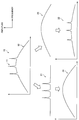
- FIG. 1 is a diagram for explaining noise targeted by the noise canceling system according to the present embodiment.
- the horizontal axis represents frequency and the vertical axis represents amplitude.
- the vehicle interior noise 10 has a noise characteristic including a first noise 11 having a narrow frequency bandwidth and a second noise 12 having a wide frequency bandwidth.
- the first noise 11 is a peaky noise that appears at a frequency that is a constant multiple of the rotational speed of an internal combustion engine (that is, the engine), for example.
- the second noise 12 is broad noise including, for example, road noise and wind noise.
- the frequency bandwidth of the first noise 11 may have a width of about ⁇ 5% with respect to the center frequency.
- the frequency bandwidth of the second noise 12 may be about 50 Hz to 300 Hz in consideration of a range that can be practically reduced (ie, canceled) by the noise canceling system.
- these values of target noise may vary depending on the design / implementation of the noise canceling system.
- the frequency of the first noise 11 varies according to the variation of the engine speed. Therefore, in order to reduce the first noise 11, it is desirable to apply an AFF (Adaptive Feedforward) type noise reduction process instead of a simple FF method.
- the noise 31 after the AFF noise reduction processing using the filter having the first characteristic 21 is applied is obtained by reducing the noise 10 to the first noise 11. Even if the frequency of the first noise 11 fluctuates in accordance with fluctuations in the engine speed, etc., the AFF type noise reduction processing is performed continuously by causing the filter characteristics to follow the fluctuations. 1 noise 11 can be reduced. However, the noise 31 still has the second noise 12 component. When a car is running, not only engine noise but also road noise and wind noise are significant. Therefore, it is not sufficient to apply AFF noise reduction processing.
- the noise reduction processing of the FB method can reduce a certain amount of noise uniformly and with a certain amount.
- noise biased to the pinpoint frequency such as engine sound is not sufficiently reduced and remains conspicuous.
- the noise 32 after the FB noise reduction process using the filter having the second characteristic 22 is applied is obtained by reducing the noise 10 to the second noise 12.
- the noise 32 still contains the component of the first noise 11. Therefore, it is not sufficient to apply the noise reduction processing of the FB method.
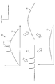
- FIG. 2 is a diagram for explaining the effect of the noise canceling system according to the present embodiment.
- the horizontal axis represents frequency
- the vertical axis represents amplitude
- the noise 10 the first characteristic 21, and the second characteristic 22 are as described above with reference to FIG. .
- noise after the AFF type filter reduction process using the filter having the first characteristic 21 and the FB type filter reduction process using the filter having the second characteristic 22 are applied.
- 33 is obtained by reducing both the first noise 11 and the second noise 12 from the target noise 10.
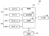
- FIG. 3 is a block diagram illustrating an example of an internal configuration of the noise canceling system according to the present embodiment.
- the noise canceling system 100 includes a microphone 110, a speaker 120, a sensor unit 130, a storage unit 140, and a control unit 170.
- Each component is connected via an in-vehicle network such as a CAN (Controller Area Network).
- CAN Controller Area Network
- the microphone 110 is an input device that picks up (that is, inputs) ambient sounds.
- the microphone 110 outputs a signal indicating the sound collection result to the control unit 170.
- the microphone 110 may have a microphone amplifier that amplifies the collected signal.
- the microphone 110 may output an analog signal or may have an ADC (Analog Digital Converter) and output a digital signal converted from the analog signal.
- ADC Analog Digital Converter
- the microphone 110 includes an AFF microphone 110A and an FB microphone 110B.
- the AFF microphone 110A is a first input device that collects sound for at least AFF noise reduction processing.
- the FB microphone 110 ⁇ / b> B is a second input device that performs sound collection for at least FB noise reduction processing.
- the speaker 120 is an output device that outputs (that is, reproduces) sound to the surroundings.
- the speaker 120 outputs sound based on the signal output from the control unit 170.
- the speaker 120 may include an amplifier that amplifies the signal.
- the speaker 120 may include a DAC (Digital Analog Converter) and output sound based on an analog signal converted from a digital signal.
- the speaker 120 includes an AFF speaker 120A and an FB speaker 120B.
- the AFF speaker 120A is a first output device that performs output for the AFF system.
- the FB speaker 120B is a second output device that performs output for the FB system.
- the sensor unit 130 has a function of detecting various information.
- the sensor unit 130 according to the present embodiment performs sensing for obtaining a reference signal for AFF noise reduction processing.
- the sensor unit 130 can be realized as a tachometer for detecting the rotational speed of the engine or a microphone for collecting engine sound.
- Storage unit 140 has a function of temporarily or permanently storing information for the operation of the noise canceling system 100.
- Control unit 170 has a function of controlling the entire operation of the noise canceling system 100. As shown in FIG. 3, the control unit 170 includes a signal processing unit 150 and a setting unit 160.
- the signal processing unit 150 has a function of applying various signal processing to the input signal and outputting it.
- the setting unit 160 has a function of setting the operation mode of the signal processing unit 150.
- the signal processing unit 150 uses both AFF noise reduction processing and FB noise reduction processing. Specifically, the signal processing unit 150 generates a first noise reduction signal using an adaptive filter based on the signal output from the AFF microphone 110A. Then, the signal processing unit 150 causes the AFF speaker 120A to output the generated first noise reduction signal. In addition, the signal processing unit 150 generates a second noise reduction signal using a fixed filter based on the signal output from the FB microphone 110B. Then, the signal processing unit 150 causes the generated second noise reduction signal to be output by the FB speaker 120B.
- the signal processing unit 150 uses two types of noise reduction processing with different characteristics in combination, so that it is possible to reduce both noises targeted by the respective methods.
- An adaptive filter is a filter in which filter coefficients are generated sequentially.
- a fixed filter is a filter in which filter coefficients are fixedly set.
- the first noise reduction signal targets noise with a narrow frequency bandwidth
- the second noise reduction signal targets noise with a wide frequency bandwidth.
- the first noise reduction signal targets noise having a narrow frequency bandwidth compared to the second noise reduction signal.
- the first noise reduction signal targets the first noise 11
- the second noise reduction signal targets the second noise 12.
- the first noise reduction signal may target noise according to the rotational speed of the power source that performs the rotational motion
- the second noise reduction signal may include the power source.
- Noise corresponding to movement by the used moving body may be targeted.
- the power source is an internal combustion engine or a motor
- the moving body is a car
- noise corresponding to movement includes, for example, road noise and wind noise.
- the signal processing unit 150 is an AFF type noise reduction process that is good at reducing peaky noise that may fluctuate, such as engine sound, and an FB type noise reduction process that is good at reducing broad noise such as road noise and wind noise. And in combination.
- the noise canceling system 100 can further reduce noise during actual driving in a vehicle over a wide band.
- the noise canceling system 100 can be realized in a form other than the in-vehicle type.
- the moving body can be variously considered such as a motorcycle, an electric bicycle, an airplane, a drone, or a ship.
- the power source can be considered variously such as a heat engine such as an external combustion engine, an electric motor, or a fluid machine.
- the noise canceling system 100 may not be mounted on the moving body. For example, it may be mounted on a fixed object such as digital signage, or may be mounted on a headphone or a smartphone.
- FIG. 4 is a diagram for explaining AFF noise reduction processing by the noise canceling system 100 according to the present embodiment. As shown in FIG. 4, this processing involves an AFF microphone 110 ⁇ / b> A, an AFF speaker 120 ⁇ / b> A, a sensor unit 130, an adaptive algorithm 151, and an FF filter (Feedforward filter) 152. Note that the adaptive algorithm 151 and the FF filter 152 are included in the signal processing unit 150.
- the sensor unit 130 acquires information indicating the rotational speed of the car engine. This information is also referred to below as the rpm signal. In a typical AFF noise reduction process, this rpm signal is defined as noise.
- the sensor unit 130 may collect the engine sound as an rpm signal instead of or together with the engine speed.
- the AFF microphone 110A outputs a signal indicating the sound collection result.
- the AFF microphone 110A collects noise in a state reduced by the first noise reduction signal output from the AFF speaker 120A.
- the AFF microphone 110A is also referred to as an error microphone, and a signal output from the AFF microphone 110A is also referred to as an error microphone signal.
- the position of the error microphone is also called a cancellation target point (or control point), and the noise cancellation effect here is the largest.
- the adaptive algorithm 151 sets the filter coefficient of the FF filter 152. Specifically, the adaptive algorithm 151 calculates a filter coefficient using the adaptive algorithm based on the reference signal output from the sensor unit 130 and the error microphone signal output from the AFF microphone 110A. Then, the adaptive algorithm 151 sequentially rewrites the filter coefficient of the FF filter 152 with the calculated filter coefficient. Examples of adaptive algorithms that can be used include LMS (Least Mean Square).
- the FF filter 152 generates a first noise reduction signal. Specifically, first, the FF filter 152 calculates a reference signal (that is, noise) based on the rpm signal output from the sensor unit 130. Next, the FF filter 152 applies (that is, convolves) the filter coefficient set by the adaptive algorithm 151 to the reference signal, thereby generating a first noise reduction signal.
- a reference signal that is, noise
- the FF filter 152 applies (that is, convolves) the filter coefficient set by the adaptive algorithm 151 to the reference signal, thereby generating a first noise reduction signal.
- the AFF speaker 120 ⁇ / b> A outputs the first noise reduction signal output from the FF filter 152.
- the AFF microphone 110 ⁇ / b> A is installed, for example, inside the ceiling of the car (that is, the inside of the car), and the AFF speaker 120 ⁇ / b> A is installed, for example, inside the door of the car (that is, the inside of the car).
- the speaker installed inside the door may be a speaker for music reproduction. That is, the signal processing unit 150 uses a music playback speaker as the AFF speaker 120A.
- a speaker for music reproduction that can be used as the AFF speaker 120A has a larger diameter than a speaker installed on a headrest of a seat that can be used as an FB speaker 120B described later.
- the music is a concept including any sound other than the noise reduction signal such as radio sound, TV sound, or navigation sound, in addition to music generally called.
- the processing includes an FB microphone 110 ⁇ / b> B, an FB speaker 120 ⁇ / b> B, and an FB filter (Feedback filter) 153.
- the FB filter 153 is included in the signal processing unit 150.
- the FB microphone 110B outputs a signal indicating the sound collection result.
- the FB microphone 110 ⁇ / b> B collects noise in a state reduced by the second noise reduction signal output from the FB speaker 120 ⁇ / b> B.
- the position of the FB microphone 110B is also called a cancellation target point, and the noise cancellation effect here is the largest.
- the FB filter 153 generates a second noise reduction signal. Specifically, the FB filter 153 generates a second noise reduction signal by applying a fixed filter coefficient to the signal output from the FB microphone 110B.
- the FB speaker 120B outputs the first noise reduction signal output from the FF filter 152.
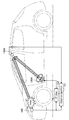
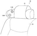
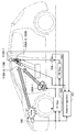
- the FB microphone 110 ⁇ / b> B and the FB speaker 120 ⁇ / b> B are installed, for example, at the user's ear in the headrest 41 of the seat (that is, the seat) 40 in the vehicle. Since the FB microphone 110B and the FB speaker 120B are installed at the ear, noise reaching the user's ear can be efficiently reduced.
- the relative positional relationship between the FB microphone 110B and the FB speaker 120B is fixed.
- the relative positional relationship is a concept including relative coordinates and relative orientation. This is because the filter coefficient is fixedly set in the FB method noise reduction processing, and it is difficult for the filter coefficient to follow a change in relative positional relationship.
- the signal processing unit 150 uses, as the FB microphone 110B and the FB speaker 120B, a microphone and a speaker provided in one component (that is, a component that does not fall apart) among one or more components forming the seat. desirable.
- the microphone and the speaker provided on the headrest 41 among the components such as the headrest 41, the seating surface 42, and the armrest that form the seat 40 are used as the FB microphone 110 ⁇ / b> B and the FB speaker 120 ⁇ / b> B. For this reason, for example, even if the seat 40 is reclined, the relative positional relationship between the FB microphone 110B and the FB speaker 120B does not change.
- an absolute position in a car means a position in a coordinate system with an arbitrary position of the car (for example, an engine or the like) as the origin.
- the filter coefficient set in the FB filter 153 may be switched according to the change in the relative positional relationship.
- the filter coefficient set in the FB filter 153 may be switched according to the height of the headrest 41.
- the filter coefficient is selected as appropriate from the filter coefficients prepared in advance, so that the degree of freedom in setting the filter coefficient is low compared to the AFF method that adaptively generates the filter coefficient.
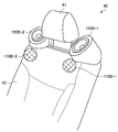
- the installation positions of the FB microphone 110B and the FB speaker 120B are not limited to the example shown in FIG.
- a microphone and a speaker provided in any one of the one or more components forming the seat can be used as the FB microphone 110B and the FB speaker 120B.
- a microphone and a speaker provided on the seat surface 42 instead of the headrest 41 in the seat 40 may be used as the FB microphone 110 ⁇ / b> B and the FB speaker 120 ⁇ / b> B.
- the FB microphone 110B-1 and the FB speaker 120B-1 are installed at a position corresponding to the left shoulder of the user on the seating surface 42, and the FB microphone 110B-2 and the FB speaker 120B-2 are seated.
- the surface 42 is installed at a position corresponding to the right shoulder of the user. Also in this example, even if the seat 40 is reclined, for example, the relative positional relationship between the FB microphones 110B-1 and 110B-2 and the FB speakers 120B-1 and 120B-2 does not change. However, for example, when the seat 40 is reclined, the absolute positions of the FB microphones 110B-1 and 110B-2 and the FB speakers 120B-1 and 120B-2 change.
- the relative positional relationship between the FB microphone 110B and the FB speaker 120B is fixed in any arrangement.
- the filter coefficient is fixedly set, so that it is difficult to make the filter coefficient follow the change in the relative positional relationship.
- the relative positional relationship between the AFF microphone 110A and the AFF speaker 120A may be fixed or variable. This is because the noise reduction processing of the AFF method can easily follow the change in relative positional relationship by adaptively generating the filter coefficient.
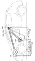
- FIG. 8 is a diagram for explaining a first arrangement of the noise canceling system 100 according to the present embodiment. According to the arrangement shown in FIG. 8, the noise canceling system 100 performs the AFF noise reduction processing and the FB noise reduction processing in parallel using devices required for each. Hereinafter, the arrangement of the microphone and the speaker will be described in detail.
- the signal processing unit 150 uses a microphone and a speaker whose relative positional relationship is fixed as the AFF microphone 110A and the AFF speaker 120A.
- the signal processing unit 150 uses a microphone and a speaker whose absolute positions are fixed as the AFF microphone 110A and the AFF speaker 120A.
- the AFF microphone 110A is installed inside the ceiling, and the AFF speaker 120A is installed inside the door.
- the signal processing unit 150 uses a microphone and a speaker whose relative positional relationship is fixed as the FB microphone 110B and the FB speaker 120B.
- the signal processing unit 150 uses microphones and speakers whose absolute positions are variable as the FB microphone 110B and the FB speaker 120B.
- the FB microphone 110B and the FB speaker 120B are installed on the headrest. For example, when the seat is reclined, the absolute position changes while the relative positional relationship between the FB microphone 110B and the FB speaker 120B is fixed.
- the noise canceling system 100 can reduce peaky noise that can fluctuate such as engine sound and broad noise such as road noise and wind noise.
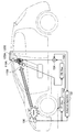
- FIG. 9 is a diagram for explaining a second arrangement of the noise canceling system 100 according to the present embodiment.
- the noise canceling system 100 performs the AFF noise reduction processing and the FB noise reduction processing using a common microphone.
- the arrangement of the microphone and the speaker will be described in detail.
- the signal processing unit 150 uses a microphone and a speaker whose relative positional relationship is variable as the AFF microphone 110A and the AFF speaker 120A.
- the AFF microphone 110A is installed on the headrest, and the AFF speaker 120A is installed inside the door.
- the signal processing unit 150 uses a microphone and a speaker whose relative positional relationship is fixed as the FB microphone 110B and the FB speaker 120B.
- the FB microphone 110B and the FB speaker 120B are installed on the headrest. For example, when the seat is reclined, the absolute position changes while the relative positional relationship between the FB microphone 110B and the FB speaker 120B is fixed.
- the signal processing unit 150 uses the same microphone whose absolute position is variable as the AFF microphone 110A and the FB microphone 110B.
- the signal processing unit 150 uses one microphone installed on the headrest as the AFF microphone 110 ⁇ / b> A and the FB microphone 110 ⁇ / b> B.
- the signals output from the microphones used as the AFF microphone 110A and the FB microphone 110B are input to the adaptive algorithm 151 to be used for generating the first noise reduction signal, and are also input to the FB filter 153 to be the second noise reduction. Used for signal generation.
- Such an arrangement eliminates the need to physically install one microphone as compared with the first arrangement, so that the configuration is simpler and system design is facilitated. Further, in this arrangement, since the cancellation target point is one point, an extra wraparound system is eliminated and oscillation is difficult to occur. Furthermore, even when the seat is reclined or the like, at least the relative positional relationship between the FB microphone 110B and the speaker 120B is fixed. Therefore, the noise canceling system 100 can stably perform FB noise reduction processing. Is possible.
- FIG. 10 is a diagram for explaining a third arrangement of the noise canceling system 100 according to the present embodiment.
- the noise canceling system 100 performs the AFF noise reduction processing and the FB noise reduction processing using a common speaker.
- the arrangement of the microphone and the speaker will be described in detail.
- the signal processing unit 150 uses a microphone and a speaker whose relative positional relationship is variable as the AFF microphone 110A and the AFF speaker 120A.
- the AFF microphone 110A is installed inside the ceiling, and the AFF speaker 120A is arranged on the headrest.
- the signal processing unit 150 uses a microphone and a speaker whose relative positional relationship is fixed as the FB microphone 110B and the FB speaker 120B.
- the FB microphone 110B and the FB speaker 120B are installed on the headrest. For example, when the seat is reclined, the absolute position changes while the relative positional relationship between the FB microphone 110B and the FB speaker 120B is fixed.
- the signal processing unit 150 uses the same speaker whose absolute position is variable as the AFF speaker 120A and the FB speaker 120B.
- the signal processing unit 150 uses one speaker installed on the headrest as the AFF speaker 120A and the FB speaker 120B.
- the speakers used as the AFF speaker 120A and the FB speaker 120B output a signal indicating the addition result of the first noise reduction signal and the second noise reduction signal by the adder 154.
- a speaker for music playback is installed inside the door.
- the music playback speaker installed inside the door is not used as the AFF speaker 120A.
- the amplifier system can be divided into the first noise reduction signal and the music reproduction signal. Such an effect can be similarly achieved even when the AFF speaker 120A is installed separately from the speaker for music reproduction without using a common speaker.
- this arrangement does not have to physically install one speaker as compared with the first arrangement, so that the same effect as the second arrangement is achieved. That is, this arrangement has a simpler configuration than the first arrangement and facilitates system design. Furthermore, even when the seat is reclined or the like, at least the relative positional relationship between the FB microphone 110B and the speaker 120B is fixed. Therefore, the noise canceling system 100 can stably perform FB noise reduction processing. Is possible.
- FIG. 11 is a diagram for explaining a fourth arrangement of the noise canceling system 100 according to the present embodiment.
- the noise canceling system 100 performs AFF noise reduction processing and FB noise reduction processing using a common microphone and a common speaker.
- AFF noise reduction processing and FB noise reduction processing using a common microphone and a common speaker.
- the signal processing unit 150 uses a microphone and a speaker whose relative positional relationship is fixed as the AFF microphone 110A and the AFF speaker 120A.
- the AFF microphone 110A and the AFF speaker 120A are installed on the headrest.
- the signal processing unit 150 uses a microphone and a speaker whose relative positional relationship is fixed as the FB microphone 110B and the FB speaker 120B.
- the FB microphone 110B and the FB speaker 120B are installed on the headrest.
- the absolute position changes while the relative positional relationship between the FB microphone 110B and the FB speaker 120B is fixed.
- the signal processing unit 150 uses the same microphone whose absolute position is variable as the AFF microphone 110A and the FB microphone 110B.
- the signal processing unit 150 uses one microphone installed on the headrest as the AFF microphone 110 ⁇ / b> A and the FB microphone 110 ⁇ / b> B.
- the signals output from the microphones used as the AFF microphone 110A and the FB microphone 110B are input to the adaptive algorithm 151 to be used for generating the first noise reduction signal, and are also input to the FB filter 153 to be the second noise reduction. Used for signal generation.
- the signal processing unit 150 uses the same speaker whose absolute position is variable as the AFF speaker 120A and the FB speaker 120B. In the example illustrated in FIG.
- the signal processing unit 150 uses one speaker installed on the headrest as the AFF speaker 120A and the FB speaker 120B.
- the speakers used as the AFF speaker 120A and the FB speaker 120B output a signal indicating the addition result of the first noise reduction signal and the second noise reduction signal by the adder 154.
- FIG. 12 is a diagram for explaining a fifth arrangement of the noise canceling system 100 according to the present embodiment.
- the noise canceling system 100 performs the AFF noise reduction processing and the FB noise reduction processing using a common microphone and a common speaker.
- the arrangement of the microphone and the speaker will be described in detail.
- the signal processing unit 150 uses a microphone and a speaker whose relative positional relationship is fixed as the AFF microphone 110A and the AFF speaker 120A.
- the AFF microphone 110A and the AFF speaker 120A are installed inside the ceiling.
- the signal processing unit 150 uses a microphone and a speaker whose relative positional relationship is fixed as the FB microphone 110B and the FB speaker 120B.
- the FB microphone 110B and the FB speaker 120B are installed inside the ceiling. For example, even if the seat is reclined, the absolute position and the relative positional relationship of the FB microphone 110B and the FB speaker 120B remain fixed.
- the signal processing unit 150 uses the same microphones whose absolute positions are fixed as the AFF microphone 110A and the FB microphone 110B.
- the signal processing unit 150 uses one microphone installed inside the ceiling as the AFF microphone 110A and the FB microphone 110B.
- the signals output from the microphones used as the AFF microphone 110A and the FB microphone 110B are input to the adaptive algorithm 151 to be used for generating the first noise reduction signal, and are also input to the FB filter 153 to be the second noise reduction. Used for signal generation.
- the signal processing unit 150 uses the same speaker whose absolute position is fixed as the AFF speaker 120A and the FB speaker 120B. In the example shown in FIG.
- the signal processing unit 150 uses one speaker installed inside the ceiling as the AFF speaker 120A and the FB speaker 120B.
- the speakers used as the AFF speaker 120A and the FB speaker 120B output a signal indicating the addition result of the first noise reduction signal and the second noise reduction signal by the adder 154.
- FIG. 13 is a diagram for explaining a sixth arrangement of the noise canceling system 100 according to the present embodiment.
- the noise canceling system 100 performs AFF noise reduction processing using a plurality of microphones and a plurality of speakers.
- the arrangement of the microphone and the speaker will be described in detail.
- the signal processing unit 150 uses a plurality of microphones and a plurality of speakers as the AFF microphone 110A and the AFF speaker 120A.
- the AFF microphone 110A-1 is installed inside the ceiling, and the AFF microphone 110A-2 is installed on the headrest.
- the AFF speaker 120A-1 is installed inside the door, and the AFF speaker 120A-2 is installed on the headrest.
- the adaptive algorithm 151 sets a plurality of filter coefficients of the FF filter 152. Specifically, the adaptive algorithm 151 calculates a filter coefficient using the adaptive algorithm based on the reference signal output from the sensor unit 130 and the error microphone signal output from the AFF microphones 110A-1 and 100A-2. Here, the adaptive algorithm 151 calculates two filter coefficients, a filter coefficient for the AFF speaker 120A-1 and a filter coefficient for the AFF speaker 120A-2. Then, the adaptive algorithm 151 sequentially rewrites the two filter coefficients set in the FF filter 152 with the calculated two filter coefficients.
- the FF filter 152 generates a plurality of first noise reduction signals for the plurality of AFF speakers 120A. Specifically, first, the FF filter 152 calculates a reference signal (that is, noise) based on the rpm signal output from the sensor unit 130. Next, the FF filter 152 generates a first noise reduction signal by applying the filter coefficient for the AFF speaker 120A-1 set by the adaptive algorithm 151 to the reference signal, and supplies the first noise reduction signal to the AFF speaker 120A-1. Output. Further, the FF filter 152 applies the filter coefficient for the AFF speaker 120A-2 set by the adaptive algorithm 151 to the reference signal (that is, convolves), thereby generating the first noise reduction signal, and the AFF The output is made to the speaker 120A-2.
- a reference signal that is, noise
- the microphone used as the AFF microphone 110A may be the same as or different from the microphone used as the FB microphone 110B.
- the signal processing unit 150 uses the microphone installed inside the ceiling as the AFF microphone 110A-1, uses one microphone installed on the headrest as the AFF microphone 110A-2, and uses the FB microphone. Used as 110B. Signals output from the microphones used as the AFF microphone 110A-2 and the FB microphone 110B are input to the adaptive algorithm 151 to be used for generating the first noise reduction signal, and are also input to the FB filter 153 to receive the second signal. Used to generate noise reduction signal
- the speaker used as the AFF speaker 120A may be the same as or different from the speaker used as the FB speaker 120B.
- the signal processing unit 150 uses the speaker installed inside the door as the AFF speaker 120A-1, uses one speaker installed in the headrest as the AFF speaker 120A-2, and uses FB. Used as the speaker 120B.
- the speakers used as the AFF speaker 120A-2 and the FB speaker 120B output a signal indicating the addition result of the first noise reduction signal and the second noise reduction signal by the adder 154.
- the relative positional relationship and absolute position of the microphone and speaker used as the AFF microphone 110A and the AFF speaker 120A may be fixed or variable.
- the relative positional relationship between the AFF microphone 110A-1 and the AFF speaker 120A-1 is fixed, while the relative positional relationship with the AFF speaker 120A-2 is variable.
- the absolute position of the AFF microphone 110A-1 is fixed, but the absolute position of the AFF microphone 110A-2 is variable.
- the setting unit 160 sets the operation mode of the signal processing unit 150.
- the signal processing unit 150 is an operation in which at least one of a microphone used as the AFF microphone 110A, a microphone used as the FB microphone 110B, a speaker used as the AFF speaker 120A, and a speaker used as the FB speaker 120B is set by the setting unit 160 Switch according to the mode.
- the noise canceling system 100 can employ an appropriate arrangement depending on the situation.
- the setting unit 160 operates according to the presence or absence of output of a signal other than a noise reduction signal (that is, the first noise reduction signal or the second noise reduction signal) from a speaker that can be used as the AFF speaker 120A. May be set. Specifically, the setting unit 160 sets the operation mode according to whether or not a music playback signal is output from a music playback speaker installed inside the door. For example, when a music playback signal is output from a music playback speaker installed inside the door, the setting unit 160 sets an operation mode that employs the third arrangement. As a result, the noise canceling system 100 can isolate the music playback speaker from the noise reduction processing when music is played back, thereby preventing a load on the music playback processing and maintaining the sound quality of the music. .
- a noise reduction signal that is, the first noise reduction signal or the second noise reduction signal
- the setting unit 160 sets the operation mode in which the first arrangement is adopted.
- the noise canceling system 100 can reduce noise more effectively in a low frequency range by using a speaker with a large aperture for music reproduction for noise reduction processing when music is not reproduced. .
- the setting unit 160 may automatically set the operation mode based on an arbitrary trigger. In that case, the noise canceling system 100 may notify the user of the set operation mode using an arbitrary output device such as a navigation device.
- the setting unit 160 may set the operation mode in accordance with a manual input from the user.
- the noise canceling system 100 may be realized as a device mounted on any type of vehicle such as an automobile, an electric vehicle, a hybrid electric vehicle, and a motorcycle. Further, at least some of the components of the noise canceling system 100 may be realized in a module for an apparatus mounted on a vehicle (for example, an integrated circuit module configured by one die).
- FIG. 14 is a block diagram illustrating an example of a schematic configuration of a vehicle control system 900 to which the technology according to the present disclosure can be applied.
- the vehicle control system 900 includes an electronic control unit 902, a storage device 904, an input device 906, a vehicle outside sensor 908, a vehicle state sensor 910, a passenger sensor 912, a communication IF 914, an output device 916, a power generation device 918, a braking device 920, a steering system. 922 and a lamp actuating device 924.
- the electronic control unit 902 functions as an arithmetic processing unit and a control unit, and controls the overall operation in the vehicle control system 900 according to various programs.
- the electronic control unit 902 can be formed as an ECU (Electronic Control Unit) together with a storage device 904 described later.
- a plurality of ECUs may be included in the vehicle control system 900.
- each of the various sensors or the various drive systems may be provided with an ECU for controlling them, and further provided with an ECU for controlling the plurality of ECUs in a coordinated manner.
- the plurality of ECUs are connected via an in-vehicle communication network that conforms to an arbitrary standard such as CAN (Controller Area Network), LIN (Local Interconnect Network), LAN (Local Area Network), or Flexray.
- the electronic control unit 902 forms, for example, one or more components (that is, the signal processing unit 150 and / or the setting unit 160) included in the control unit 170 shown in FIG. In the present embodiment, the electronic control unit 902 generates a first noise reduction signal and a second noise reduction signal.
- the storage device 904 is a data storage device formed as an example of a storage unit of the vehicle control system 900.
- the storage apparatus 904 is realized by, for example, a magnetic storage device such as an HDD, a semiconductor storage device, an optical storage device, a magneto-optical storage device, or the like.
- the storage device 904 may include a storage medium, a recording device that records data on the storage medium, a reading device that reads data from the storage medium, a deletion device that deletes data recorded on the storage medium, and the like.
- the storage device 904 stores programs executed by the electronic control unit 902, various data, various data acquired from the outside, and the like.
- the storage device 904 can form the storage unit 140 shown in FIG. 3, for example.
- the input device 906 is realized by a device in which information is input by a passenger (driver or passenger) such as a mouse, a keyboard, a touch panel, a button, a microphone, a switch, and a lever.
- the input device 906 may be, for example, a remote control device using infrared rays or other radio waves, or may be an external connection device such as a mobile phone or a PDA corresponding to the operation of the vehicle control system 900.
- the input device 906 may be a camera, for example, and in that case, the passenger can input information by gesture.
- the input device 906 may include, for example, an input control circuit that generates an input signal based on information input by the user using the above-described input means and outputs the input signal to the electronic control unit 902.
- the passenger can operate the input device 906 to input various data to the vehicle control system 900 and to instruct processing operations.
- the vehicle outside sensor 908 is realized by a sensor that detects information outside the vehicle.
- the outside sensor 908 includes a sonar device, a radar device, a LIDAR (Light Detection and Ranging, Laser Imaging Detection and Ranging) device, a camera, a stereo camera, a ToF (Time Of Flight) camera, an infrared sensor, an environmental sensor, a microphone, and the like. May be included.
- Vehicle state sensor 910 is realized by a sensor that detects information related to the vehicle state.
- the vehicle state sensor 910 may include a sensor that detects an operation by the driver such as an accelerator opening, a brake depression pressure, or a steering angle.
- the vehicle state sensor 910 may include a sensor that detects the state of the power source, such as the rotational speed or torque of the internal combustion engine or motor.
- the vehicle state sensor 910 may include a sensor for detecting information related to the movement of the vehicle such as a gyro sensor or an acceleration sensor.
- the vehicle state sensor 910 receives a GNSS signal (for example, a GPS signal from a GPS (Global Positioning System) satellite) from a GNSS (Global Navigation Satellite System) satellite, and includes position information including the latitude, longitude, and altitude of the device.
- a GNSS module may be included.
- the vehicle state sensor 910 may detect the position by transmission / reception with Wi-Fi (registered trademark), a mobile phone / PHS / smartphone or the like, or near field communication.
- Wi-Fi registered trademark
- the vehicle state sensor 910 can form, for example, the sensor unit 130 shown in FIG.
- the passenger sensor 912 is realized by a sensor that detects information related to the passenger.
- the passenger sensor 912 may include a camera, a microphone, and an environment sensor provided in the vehicle.
- the passenger sensor 912 may include a biological sensor that detects biological information of the passenger.
- the biometric sensor is provided on, for example, a seat surface or a steering wheel, and can detect biometric information of a passenger sitting on the seat or a driver who holds the steering wheel.
- the occupant sensor 912 can form, for example, the microphone 110 shown in FIG. In the present embodiment, a microphone 110 is formed on the inside of the door, the inside of the ceiling, or the headrest, and detects sound in the vehicle.
- various sensors such as the outside sensor 908, the vehicle state sensor 910, and the passenger sensor 912 each output information indicating the detection result to the electronic control unit 902. These various sensors may set a sensing range or accuracy based on control by the electronic control unit 902. These various sensors include a recognition module that performs recognition processing based on raw data such as processing for recognizing the traveling position of the host vehicle on the road based on the position of the white line included in the captured image. Also good.
- the communication IF 914 is a communication interface that mediates communication with other devices by the vehicle control system 900.
- the communication IF 914 may include, for example, a V2X communication module.
- V2X communication is a concept including vehicle-to-vehicle (Vehicle to Vehicle) communication and road-to-vehicle (Vehicle to Infrastructure) communication.
- the communication IF 914 can be a wireless local area network (LAN), Wi-Fi (registered trademark), 3G, LTE (Long Term Evolution), Bluetooth (registered trademark), NFC (Near Field Communication), or WUSB (Wireless USB). ) Communication module.
- the communication IF 914 can transmit and receive signals and the like according to a predetermined protocol such as TCP / IP, for example, with the Internet or a communication device outside the vehicle.
- the output device 916 is realized by a device that can notify the passenger of the acquired information visually or audibly.
- Such devices include display devices such as instrument panels, head-up displays, projectors or lamps, and audio output devices such as speakers or headphones.
- the display device visually displays the results obtained by various processes performed by the vehicle control system 900 in various formats such as text, images, tables, and graphs. At that time, a virtual object such as an AR (Augmented Reality) object may be displayed.
- the audio output device converts an audio signal composed of reproduced audio data, acoustic data, and the like into an analog signal and outputs it aurally.
- the audio output device can form, for example, the speaker 120 shown in FIG. In the present embodiment, the speaker 120 is formed inside the door, inside the ceiling, or headrest, and the first noise reduction signal and the second noise reduction signal are output.
- the power generation device 918 is a device for generating a driving force of the vehicle.
- the power generation device 918 may be realized by an internal combustion engine, for example. In that case, the power generation device 918 performs start control, stop control, throttle valve opening control, fuel injection control, EGR (Exhaust Gas Recirculation) control, and the like based on a control command from the electronic control unit 902. .
- the power generation device 918 may be realized by, for example, a motor, an inverter, and a battery. In that case, the power generation device 918 supplies electric power from the battery to the motor via the inverter based on a control command from the electronic control unit 902 and outputs a positive torque, so-called power running, and torque to the motor. And a regenerative operation of charging the battery via an inverter.
- the braking device 920 is a device for applying a braking force to the vehicle, or decelerating or stopping the vehicle.
- the braking device 920 may include, for example, a brake installed on each wheel, a brake pipe or an electric circuit for transmitting the depression pressure of the brake pedal to the brake, and the like.
- the braking device 920 may include a control device for operating a sliding or skid prevention mechanism by brake control such as ABS (Antilock Brake System) or ESC (Electronic Stability Control).
- Steering 922 is a device for controlling the traveling direction (steering angle) of the vehicle.
- the steering 922 can include, for example, a steering wheel, a steering shaft, a steering gear, and a tie rod.
- the steering 922 may include power steering for assisting steering by the driver.
- the steering 922 may include a power source such as a motor for realizing automatic steering.
- the lamp operating device 924 is a device that operates various lamps such as a headlight, a blinker, a vehicle width light, a fog light, or a stop lamp.
- the lamp operating device 924 controls, for example, the blinking of the lamp, the amount of light, or the irradiation direction.
- the power generation device 918, the braking device 920, the steering 922, and the lamp operation device 924 may operate based on a manual operation by a driver or may operate based on an automatic operation by the electronic control unit 902. .
- each of the above components may be realized using a general-purpose member, or may be realized by hardware specialized for the function of each component. Therefore, it is possible to change the hardware configuration to be used as appropriate according to the technical level at the time of carrying out this embodiment.
- a computer program for realizing each function of the noise canceling system 100 according to the present embodiment as described above can be produced and installed in an ECU or the like.
- a computer-readable recording medium storing such a computer program can be provided.
- the recording medium is, for example, a magnetic disk, an optical disk, a magneto-optical disk, a flash memory, or the like.
- the above computer program may be distributed via a network, for example, without using a recording medium.
- the noise canceling system 100 generates the first noise reduction signal using the adaptive filter based on the signal output from the first input device, and generates the first noise reduction signal.
- the first noise reduction signal is output by the first output device
- the second noise reduction signal is generated using the fixed filter based on the signal output from the second input device
- the generated second noise is generated.
- the reduced signal is output by the second output device.
- the noise canceling system 100 uses an adaptive filter that is good at reducing peaky noise that can fluctuate such as engine sound, and a fixed filter that is good at reducing broad noise such as road noise and wind noise. . Therefore, the noise canceling system 100 according to the present embodiment can reduce more noise during actual driving in a vehicle in a wide band.
- the noise canceling system 100 described in this specification may be realized as a single device, or a part or all of the noise canceling system 100 may be realized as a separate device.
- the storage unit 140, the signal processing unit 150, and the setting unit 160 are connected to the microphone 110, the speaker 120, and the sensor unit 130 via a network or the like. It may be provided in a device such as a server.
- the signal processing described with reference to FIG. 4 and the like is executed in the order along the data flow indicated by the arrows. However, additional processing steps may be added. Further, the AFF noise reduction process and the FB noise reduction process can be executed in parallel.
- a signal processing unit that generates a second noise reduction signal using a fixed filter based on a signal output from the second input device, and causes the second output device to output the generated second noise reduction signal
- a signal processing apparatus comprising: (2) The first noise reduction signal targets noise having a narrow frequency bandwidth, The signal processing apparatus according to (1), wherein the second noise reduction signal targets noise having a wide frequency bandwidth.
- the first noise reduction signal is targeted for noise according to the rotational speed of a power source that performs rotational motion
- the power source is an internal combustion engine or a motor
- the moving body is a car.
- the signal processing unit uses, as the first input device and the first output device, an input device and an output device whose relative positional relationship is fixed, and an input device whose relative positional relationship is fixed, and The signal processing device according to any one of (1) to (4), wherein an output device is used as the second input device and the second output device.
- the signal processing unit uses an input device and an output device whose absolute positions are fixed as the first input device and the first output device, The signal processing device according to (5), wherein an input device and an output device whose absolute positions are variable are used as the second input device and the second output device. (7) The signal processing unit uses the same input device whose absolute position is variable as the first input device and the second input device, and uses the same output device whose absolute position is variable as the first output device. The signal processing device according to (5), which is used as a device and a second output device. (8) The signal processing unit uses the same input device whose absolute position is fixed as the first input device and the second input device, and uses the same output device whose absolute position is fixed as the first input device.
- the signal processing device which is used as an output device and a second output device.
- the signal processing unit uses an input device and an output device whose relative positional relationship is variable as the first input device and the first output device, and the input device and the output whose relative positional relationship is fixed
- the signal processing device according to any one of (1) to (4), wherein a device is used as the second input device and the second output device.
- the signal processing device according to (9), wherein the signal processing unit uses the same input device whose absolute position is variable as the first input device and the second input device.
- the signal processing unit 150 is the signal processing device according to (9), wherein the same output device whose absolute position is variable is used as the first output device and the second output device.
- the signal processing unit according to any one of (1) to (11), wherein the signal processing unit uses a plurality of input devices and a plurality of output devices as the first input device and the first output device. Processing equipment. (13) The signal processing device according to any one of (1) to (12), wherein the signal processing unit uses an output device for music reproduction as the first output device. (14) The signal processing unit uses, as the second input device and the second output device, an input device and an output device provided in one component among one or more components forming a seat. The signal processing device according to any one of (13).
- a setting unit for setting an operation mode of the signal processing unit is an input device used as the first input device, an input device used as the second input device, an output device used as the first output device, or an output device used as the second output device.
- the signal processing device according to any one of (1) to (14), wherein at least one of the switching is switched according to the operation mode set by the setting unit.
- the setting unit sets the operation mode according to whether or not a signal other than the first noise reduction signal or the second noise reduction signal is output from an output device that can be used as the first output device.
- a method performed by a processor including: (18) Computer Generating a first noise reduction signal using an adaptive filter based on a signal output from the first input device, and causing the first output device to output the generated first noise reduction signal; A signal processing unit that generates a second noise reduction signal using a fixed filter based on a signal output from the second input device, and causes the second output device to output the generated second noise reduction signal , A recording medium on which a program for functioning as a program is recorded.
Abstract
[Problem] To provide a mechanism that makes it possible to efficiently reduce noise containing a component the characteristics of which fluctuate. [Solution] A signal processing device provided with a signal processing unit that: generates, by using an adaptive filter, a first noise reduction signal on the basis of a signal output from a first input device; causes a first output device to output the generated first noise reduction signal; generates, by using a static filter, a second noise reduction signal on the basis of a signal output from a second input device; and causes a second output device to output the generated second noise reduction signal.
Description
本開示は、信号処理装置、方法及びプログラムに関する。
The present disclosure relates to a signal processing device, a method, and a program.
近年、ノイズキャンセリング(ノイズ低減)技術が広く開発されている。ノイズ低減技術には、大別すると、FF(Feedforward)方式とFB(Feedback)方式との2つの方式がある。これらの方式は、対象とするノイズに応じて使い分けられる場合が多い。
In recent years, noise canceling (noise reduction) technology has been widely developed. Broadly speaking, there are two types of noise reduction techniques, FF (Feedforward) and FB (Feedback). These methods are often used properly according to the target noise.
一方で、これらのノイズ低減技術を組み合わるアイディアも存在する。例えば、下記特許文献1に、FF方式とFB方式とを組み合わせることで、ヘッドホンにおけるノイズ低減効果を高める技術が開示されている。
On the other hand, there are also ideas that combine these noise reduction technologies. For example, Patent Literature 1 below discloses a technique for enhancing the noise reduction effect in headphones by combining the FF method and the FB method.
しかし、上記特許文献1で開示されているような、FF方式とFB方式との組み合わせでは、ノイズ低減効果が限定的になる場合があった。例えば、特性が変動する成分を含むノイズに関しては、ノイズ低減効果が限定的になり得る。
However, the combination of the FF method and the FB method as disclosed in Patent Document 1 described above sometimes has a limited noise reduction effect. For example, with respect to noise including components whose characteristics vary, the noise reduction effect can be limited.
そこで、本開示では、特性が変動する成分を含むノイズを効率的に低減することが可能な仕組みを提供する。
Therefore, the present disclosure provides a mechanism capable of efficiently reducing noise including components whose characteristics vary.
本開示によれば、第1の入力装置から出力された信号に基づいて適応型フィルタを用いて第1のノイズ低減信号を生成し、生成した前記第1のノイズ低減信号を第1の出力装置により出力させ、第2の入力装置から出力された信号に基づいて固定型フィルタを用いて第2のノイズ低減信号を生成し、生成した前記第2のノイズ低減信号を第2の出力装置により出力させる信号処理部、を備える信号処理装置が提供される。
According to the present disclosure, a first noise reduction signal is generated using an adaptive filter based on a signal output from a first input device, and the generated first noise reduction signal is used as the first output device. And generating a second noise reduction signal using a fixed filter based on the signal output from the second input device, and outputting the generated second noise reduction signal by the second output device. A signal processing device including a signal processing unit is provided.
また、本開示によれば、第1の入力装置から出力された信号に基づいて適応型フィルタを用いて第1のノイズ低減信号を生成し、生成した前記第1のノイズ低減信号を第1の出力装置により出力させ、第2の入力装置から出力された信号に基づいて固定型フィルタを用いて第2のノイズ低減信号を生成し、生成した前記第2のノイズ低減信号を第2の出力装置により出力させること、を含むプロセッサにより実行される方法が提供される。
According to the present disclosure, the first noise reduction signal is generated using an adaptive filter based on the signal output from the first input device, and the generated first noise reduction signal is converted into the first noise reduction signal. A second noise reduction signal is generated using a fixed filter based on the signal output from the output device and output from the second input device, and the generated second noise reduction signal is output to the second output device. A method executed by a processor is provided.
また、本開示によれば、コンピュータを、第1の入力装置から出力された信号に基づいて適応型フィルタを用いて第1のノイズ低減信号を生成し、生成した前記第1のノイズ低減信号を第1の出力装置により出力させ、第2の入力装置から出力された信号に基づいて固定型フィルタを用いて第2のノイズ低減信号を生成し、生成した前記第2のノイズ低減信号を第2の出力装置により出力させる信号処理部、として機能させるためのプログラムが記録された記録媒体が提供される。
According to the present disclosure, the computer generates a first noise reduction signal using an adaptive filter based on a signal output from the first input device, and the generated first noise reduction signal is output from the computer. Based on the signal output from the first output device and output from the second input device, a second noise reduction signal is generated using a fixed filter, and the generated second noise reduction signal is output as the second noise reduction signal. There is provided a recording medium on which a program for functioning as a signal processing unit to be output by the output device is recorded.
以上説明したように本開示によれば、特性が変動する成分を含むノイズを効率的に低減することが可能な仕組みが提供される。なお、上記の効果は必ずしも限定的なものではなく、上記の効果とともに、または上記の効果に代えて、本明細書に示されたいずれかの効果、または本明細書から把握され得る他の効果が奏されてもよい。
As described above, according to the present disclosure, a mechanism capable of efficiently reducing noise including components whose characteristics fluctuate is provided. Note that the above effects are not necessarily limited, and any of the effects shown in the present specification, or other effects that can be grasped from the present specification, together with or in place of the above effects. May be played.
以下に添付図面を参照しながら、本開示の好適な実施の形態について詳細に説明する。なお、本明細書及び図面において、実質的に同一の機能構成を有する構成要素については、同一の符号を付することにより重複説明を省略する。
Hereinafter, preferred embodiments of the present disclosure will be described in detail with reference to the accompanying drawings. In addition, in this specification and drawing, about the component which has the substantially same function structure, duplication description is abbreviate | omitted by attaching | subjecting the same code | symbol.
なお、説明は以下の順序で行うものとする。
1.概要
2.基本的な構成例
2.1.内部構成例
2.2.AFF方式のノイズ低減処理
2.3.FB方式のノイズ低減処理
3.構成のバリエーション
3.1.第1の配置
3.2.第2の配置
3.3.第3の配置
3.4.第4の配置
3.5.第5の配置
3.6.第6の配置
3.7.配置の切り替え
4.ハードウェア構成例
5.まとめ The description will be made in the following order.
1.Overview 2. Basic configuration example 2.1. Internal configuration example 2.2. AFF noise reduction processing 2.3. 2. FB noise reduction processing Configuration variations 3.1. First arrangement 3.2. Second arrangement 3.3. Third arrangement 3.4. Fourth arrangement 3.5. Fifth arrangement 3.6. Sixth arrangement 3.7. Change of arrangement 4. 4. Hardware configuration example Summary
1.概要
2.基本的な構成例
2.1.内部構成例
2.2.AFF方式のノイズ低減処理
2.3.FB方式のノイズ低減処理
3.構成のバリエーション
3.1.第1の配置
3.2.第2の配置
3.3.第3の配置
3.4.第4の配置
3.5.第5の配置
3.6.第6の配置
3.7.配置の切り替え
4.ハードウェア構成例
5.まとめ The description will be made in the following order.
1.
<<1.概要>>
本開示の一実施形態に係る信号処理装置(以下、ノイズキャンセリングシステム(即ち、ノイズ低減システム)とも称する)は、多様な形態で実現され得る。以下では、一例として、ノイズキャンセリングシステムが、車載型として実現される場合について説明する。まず、図1を参照して、車載型のノイズキャンセリングシステムが対象とするノイズについて説明する。 << 1. Overview >>
A signal processing device according to an embodiment of the present disclosure (hereinafter also referred to as a noise canceling system (that is, a noise reduction system)) can be realized in various forms. Below, the case where a noise canceling system is implement | achieved as a vehicle-mounted type is demonstrated as an example. First, with reference to FIG. 1, noise targeted by an in-vehicle noise canceling system will be described.
図1は、本実施形態に係るノイズキャンセリングシステムが対象とするノイズを説明するための図である。図1における各グラフは、横軸が周波数であり、縦軸が振幅である。走行中の車内のノイズ10は、周波数帯域幅が狭い第1のノイズ11と周波数帯域幅が広い第2のノイズ12とを含むノイズ特性を有する。第1のノイズ11は、例えば内燃機関(即ち、エンジン)の回転数の定数倍の周波数において出現する、ピーキーなノイズである。第2のノイズ12は、例えばロードノイズ及び風切り音等を含むブロードなノイズである。例えば、第1のノイズ11の周波数帯域幅は、中心周波数に対して±5%程度の幅を有していてもよい。また、第2のノイズ12の周波数帯域幅は、ノイズキャンセリングシステムが現実的に低減(即ち、キャンセル)可能な範囲を考慮して、50Hz~300Hz程度であってもよい。もちろん、対象ノイズのこれらの値は、ノイズキャンセリングシステムの設計/実装に応じて変わり得る。
FIG. 1 is a diagram for explaining noise targeted by the noise canceling system according to the present embodiment. In each graph in FIG. 1, the horizontal axis represents frequency and the vertical axis represents amplitude. The vehicle interior noise 10 has a noise characteristic including a first noise 11 having a narrow frequency bandwidth and a second noise 12 having a wide frequency bandwidth. The first noise 11 is a peaky noise that appears at a frequency that is a constant multiple of the rotational speed of an internal combustion engine (that is, the engine), for example. The second noise 12 is broad noise including, for example, road noise and wind noise. For example, the frequency bandwidth of the first noise 11 may have a width of about ± 5% with respect to the center frequency. Further, the frequency bandwidth of the second noise 12 may be about 50 Hz to 300 Hz in consideration of a range that can be practically reduced (ie, canceled) by the noise canceling system. Of course, these values of target noise may vary depending on the design / implementation of the noise canceling system.
第1のノイズ11は、エンジンの回転数の変動に応じて周波数が変動する。そのため、第1のノイズ11を低減するためには、単なるFF方式ではなく、AFF(Adaptive Feedforward)方式のノイズ低減処理の適用が望ましい。例えば、第1の特性21を有するフィルタを用いたAFF方式のノイズ低減処理が適用された後のノイズ31は、ノイズ10から第1のノイズ11が低減されたものとなる。AFF方式のノイズ低減処理は、エンジンの回転数の変動等に応じて第1のノイズ11の周波数が変動する場合であっても、フィルタの特性をその変動に追従させることで、継続的に第1のノイズ11を低減することが可能である。しかしながら、ノイズ31には、第2のノイズ12の成分が依然として残ることとなる。車の走行時には、エンジン音だけではなく、ロードノイズ及び風切り音などの影響が大きい。そのため、AFF方式のノイズ低減処理の適用だけでは十分ではない。
The frequency of the first noise 11 varies according to the variation of the engine speed. Therefore, in order to reduce the first noise 11, it is desirable to apply an AFF (Adaptive Feedforward) type noise reduction process instead of a simple FF method. For example, the noise 31 after the AFF noise reduction processing using the filter having the first characteristic 21 is applied is obtained by reducing the noise 10 to the first noise 11. Even if the frequency of the first noise 11 fluctuates in accordance with fluctuations in the engine speed, etc., the AFF type noise reduction processing is performed continuously by causing the filter characteristics to follow the fluctuations. 1 noise 11 can be reduced. However, the noise 31 still has the second noise 12 component. When a car is running, not only engine noise but also road noise and wind noise are significant. Therefore, it is not sufficient to apply AFF noise reduction processing.
一方で、第2のノイズ12を低減するためには、FB方式のノイズ低減処理の適用が望ましい。FB方式のノイズ低減処理は、様々なノイズをおしなべて均一にある程度の量低減させることが可能である。ただし、エンジン音などのピンポイントの周波数に偏ったノイズは、十分には低減されず目立ったままとなる。例えば、第2の特性22を有するフィルタを用いたFB方式のノイズ低減処理が適用された後のノイズ32は、ノイズ10から第2のノイズ12が低減されたものとなる。しかながら、ノイズ32には、第1のノイズ11の成分が依然として残ることとなる。そのため、FB方式のノイズ低減処理の適用だけでは十分ではない。
On the other hand, in order to reduce the second noise 12, it is desirable to apply an FB method noise reduction process. The noise reduction processing of the FB method can reduce a certain amount of noise uniformly and with a certain amount. However, noise biased to the pinpoint frequency such as engine sound is not sufficiently reduced and remains conspicuous. For example, the noise 32 after the FB noise reduction process using the filter having the second characteristic 22 is applied is obtained by reducing the noise 10 to the second noise 12. However, the noise 32 still contains the component of the first noise 11. Therefore, it is not sufficient to apply the noise reduction processing of the FB method.
そこで、本実施形態では、AFF方式のノイズ低減処理とFB方式のノイズ低減処理とを併用するノイズキャンセリングシステムを提案する。図2は、本実施形態に係るノイズキャンセリングシステムによる効果を説明するための図である。図2における各グラフは、横軸が周波数であり、縦軸が振幅であり、ノイズ10、第1の特性21及び第2の特性22に関しては、図1を参照して上記説明した通りである。図2に示すように、第1の特性21を有するフィルタを用いたAFF方式のフィルタ低減処理と第2の特性22を有するフィルタを用いたFB方式のフィルタ低減処理とが適用された後のノイズ33は、対象のノイズ10から第1のノイズ11及び第2のノイズ12の両方が低減されたものとなる。
Therefore, in this embodiment, a noise canceling system that uses both AFF noise reduction processing and FB noise reduction processing is proposed. FIG. 2 is a diagram for explaining the effect of the noise canceling system according to the present embodiment. In each graph in FIG. 2, the horizontal axis represents frequency, the vertical axis represents amplitude, and the noise 10, the first characteristic 21, and the second characteristic 22 are as described above with reference to FIG. . As shown in FIG. 2, noise after the AFF type filter reduction process using the filter having the first characteristic 21 and the FB type filter reduction process using the filter having the second characteristic 22 are applied. 33 is obtained by reducing both the first noise 11 and the second noise 12 from the target noise 10.
<<2.基本的な構成例>>
以下、図3~図7を参照して、本実施形態に係るノイズキャンセリングシステムの基本的な構成例を説明する。 << 2. Basic configuration example >>
Hereinafter, a basic configuration example of the noise canceling system according to the present embodiment will be described with reference to FIGS.
以下、図3~図7を参照して、本実施形態に係るノイズキャンセリングシステムの基本的な構成例を説明する。 << 2. Basic configuration example >>
Hereinafter, a basic configuration example of the noise canceling system according to the present embodiment will be described with reference to FIGS.
<2.1.内部構成例>
図3は、本実施形態に係るノイズキャンセリングシステムの内部構成の一例を示すブロック図である。図3に示すように、本実施形態に係るノイズキャンセリングシステム100は、マイク110、スピーカ120、センサ部130、記憶部140及び制御部170を含む。なお、各構成要素は、CAN(Controller Area Network)等の車載ネットワークを介して接続される。 <2.1. Internal configuration example>
FIG. 3 is a block diagram illustrating an example of an internal configuration of the noise canceling system according to the present embodiment. As illustrated in FIG. 3, thenoise canceling system 100 according to the present embodiment includes a microphone 110, a speaker 120, a sensor unit 130, a storage unit 140, and a control unit 170. Each component is connected via an in-vehicle network such as a CAN (Controller Area Network).
図3は、本実施形態に係るノイズキャンセリングシステムの内部構成の一例を示すブロック図である。図3に示すように、本実施形態に係るノイズキャンセリングシステム100は、マイク110、スピーカ120、センサ部130、記憶部140及び制御部170を含む。なお、各構成要素は、CAN(Controller Area Network)等の車載ネットワークを介して接続される。 <2.1. Internal configuration example>
FIG. 3 is a block diagram illustrating an example of an internal configuration of the noise canceling system according to the present embodiment. As illustrated in FIG. 3, the
(1)マイク110
マイク110は、周囲の音を収音(即ち、入力)する入力装置である。マイク110は、収音結果を示す信号を制御部170に出力する。マイク110は、収音した信号を増幅するマイクアンプを有していてもよい。また、マイク110は、アナログ信号を出力してもよいし、ADC(Analog Digital Converter)を有し、アナログ信号から変換されたデジタル信号を出力してもよい。 (1)Microphone 110
Themicrophone 110 is an input device that picks up (that is, inputs) ambient sounds. The microphone 110 outputs a signal indicating the sound collection result to the control unit 170. The microphone 110 may have a microphone amplifier that amplifies the collected signal. The microphone 110 may output an analog signal or may have an ADC (Analog Digital Converter) and output a digital signal converted from the analog signal.
マイク110は、周囲の音を収音(即ち、入力)する入力装置である。マイク110は、収音結果を示す信号を制御部170に出力する。マイク110は、収音した信号を増幅するマイクアンプを有していてもよい。また、マイク110は、アナログ信号を出力してもよいし、ADC(Analog Digital Converter)を有し、アナログ信号から変換されたデジタル信号を出力してもよい。 (1)
The
図3に示すように、マイク110は、AFFマイク110A及びFBマイク110Bを含む。AFFマイク110Aは、少なくともAFF方式のノイズ低減処理のための収音を行う第1の入力装置である。FBマイク110Bは、少なくともFB方式のノイズ低減処理のための収音を行う第2の入力装置である。
As shown in FIG. 3, the microphone 110 includes an AFF microphone 110A and an FB microphone 110B. The AFF microphone 110A is a first input device that collects sound for at least AFF noise reduction processing. The FB microphone 110 </ b> B is a second input device that performs sound collection for at least FB noise reduction processing.
(2)スピーカ120
スピーカ120は、周囲に音を出力(即ち、再生)する出力装置である。スピーカ120は、制御部170から出力された信号に基づいて音を出力する。スピーカ120は、信号を増幅するアンプを有していてもよい。また、スピーカ120は、DAC(Digital Analog Converter)を有し、デジタル信号から変換されたアナログ信号に基づいて音を出力してもよい。 (2)Speaker 120
Thespeaker 120 is an output device that outputs (that is, reproduces) sound to the surroundings. The speaker 120 outputs sound based on the signal output from the control unit 170. The speaker 120 may include an amplifier that amplifies the signal. The speaker 120 may include a DAC (Digital Analog Converter) and output sound based on an analog signal converted from a digital signal.
スピーカ120は、周囲に音を出力(即ち、再生)する出力装置である。スピーカ120は、制御部170から出力された信号に基づいて音を出力する。スピーカ120は、信号を増幅するアンプを有していてもよい。また、スピーカ120は、DAC(Digital Analog Converter)を有し、デジタル信号から変換されたアナログ信号に基づいて音を出力してもよい。 (2)
The
図3に示すように、スピーカ120は、AFFスピーカ120A及びFBスピーカ120Bを含む。AFFスピーカ120Aは、AFF方式のための出力を行う第1の出力装置である。FBスピーカ120Bは、FB方式のための出力を行う第2の出力装置である。
As shown in FIG. 3, the speaker 120 includes an AFF speaker 120A and an FB speaker 120B. The AFF speaker 120A is a first output device that performs output for the AFF system. The FB speaker 120B is a second output device that performs output for the FB system.
(3)センサ部130
センサ部130は、各種情報を検出する機能を有する。本実施形態に係るセンサ部130は、AFF方式のノイズ低減処理のための参照信号を得るためのセンシングを行う。例えば、センサ部130は、エンジンの回転数を検出するための回転計、又はエンジン音を収音するためのマイクとして実現され得る。 (3)Sensor unit 130
Thesensor unit 130 has a function of detecting various information. The sensor unit 130 according to the present embodiment performs sensing for obtaining a reference signal for AFF noise reduction processing. For example, the sensor unit 130 can be realized as a tachometer for detecting the rotational speed of the engine or a microphone for collecting engine sound.
センサ部130は、各種情報を検出する機能を有する。本実施形態に係るセンサ部130は、AFF方式のノイズ低減処理のための参照信号を得るためのセンシングを行う。例えば、センサ部130は、エンジンの回転数を検出するための回転計、又はエンジン音を収音するためのマイクとして実現され得る。 (3)
The
(4)記憶部140
記憶部140は、ノイズキャンセリングシステム100の動作のための情報を一時的に、又は恒久的に記憶する機能を有する。 (4)Storage unit 140
Thestorage unit 140 has a function of temporarily or permanently storing information for the operation of the noise canceling system 100.
記憶部140は、ノイズキャンセリングシステム100の動作のための情報を一時的に、又は恒久的に記憶する機能を有する。 (4)
The
(5)制御部170
制御部170は、ノイズキャンセリングシステム100の動作全体を制御する機能を有する。図3に示すように、制御部170は、信号処理部150及び設定部160を含む。 (5)Control unit 170
Thecontrol unit 170 has a function of controlling the entire operation of the noise canceling system 100. As shown in FIG. 3, the control unit 170 includes a signal processing unit 150 and a setting unit 160.
制御部170は、ノイズキャンセリングシステム100の動作全体を制御する機能を有する。図3に示すように、制御部170は、信号処理部150及び設定部160を含む。 (5)
The
信号処理部150は、入力された信号に各種信号処理を適用して出力する機能を有する。設定部160は、信号処理部150の動作モードを設定する機能を有する。
The signal processing unit 150 has a function of applying various signal processing to the input signal and outputting it. The setting unit 160 has a function of setting the operation mode of the signal processing unit 150.
以下、信号処理部150について詳しく説明する。本実施形態に係る信号処理部150は、AFF方式のノイズ低減処理とFB方式のノイズ低減処理とを併用する。具体的には、信号処理部150は、AFFマイク110Aから出力された信号に基づいて適応型フィルタを用いて第1のノイズ低減信号を生成する。そして、信号処理部150は、生成した第1のノイズ低減信号をAFFスピーカ120Aにより出力させる。また、信号処理部150は、FBマイク110Bから出力された信号に基づいて固定型フィルタを用いて第2のノイズ低減信号を生成する。そして、信号処理部150は、生成した第2のノイズ低減信号をFBスピーカ120Bにより出力させる。このように、信号処理部150は、特性の異なる2つの方式のノイズ低減処理を併用するので、各々の方式が対象とするノイズを共に低減させることが可能となる。なお、適応型フィルタは、フィルタ係数が逐次的に生成されるフィルタである。また、固定型フィルタとは、フィルタ係数が固定的に設定されるフィルタである。
Hereinafter, the signal processing unit 150 will be described in detail. The signal processing unit 150 according to the present embodiment uses both AFF noise reduction processing and FB noise reduction processing. Specifically, the signal processing unit 150 generates a first noise reduction signal using an adaptive filter based on the signal output from the AFF microphone 110A. Then, the signal processing unit 150 causes the AFF speaker 120A to output the generated first noise reduction signal. In addition, the signal processing unit 150 generates a second noise reduction signal using a fixed filter based on the signal output from the FB microphone 110B. Then, the signal processing unit 150 causes the generated second noise reduction signal to be output by the FB speaker 120B. As described above, the signal processing unit 150 uses two types of noise reduction processing with different characteristics in combination, so that it is possible to reduce both noises targeted by the respective methods. An adaptive filter is a filter in which filter coefficients are generated sequentially. A fixed filter is a filter in which filter coefficients are fixedly set.
第1のノイズ低減信号は、周波数帯域幅が狭いノイズを対象とし、第2のノイズ低減信号は、周波数帯域幅が広いノイズを対象とする。換言すると、第1のノイズ低減信号は、第2のノイズ低減信号と比較して周波数帯域幅が狭いノイズを対象とする。図1に示した例に関しては、第1のノイズ低減信号は、第1のノイズ11を対象とし、第2のノイズ低減信号は、第2のノイズ12を対象とする。
The first noise reduction signal targets noise with a narrow frequency bandwidth, and the second noise reduction signal targets noise with a wide frequency bandwidth. In other words, the first noise reduction signal targets noise having a narrow frequency bandwidth compared to the second noise reduction signal. In the example shown in FIG. 1, the first noise reduction signal targets the first noise 11, and the second noise reduction signal targets the second noise 12.
対象とするノイズについて具体的に言えば、第1のノイズ低減信号は、回転運動を行う動力源の回転数に応じたノイズを対象としてもよく、第2のノイズ低減信号は、当該動力源を用いた移動体による移動に応じたノイズを対象としてもよい。車載型の場合、当該動力源は内燃機関又はモータであり、移動体は車であり、移動に応じたノイズは例えばロードノイズ及び風切り音等を含む。信号処理部150は、エンジン音等の変動し得るピーキーなノイズの低減が得意なAFF方式のノイズ低減処理と、ロードノイズ及び風切り音等のブロードなノイズの低減が得意なFB方式のノイズ低減処理とを併用する。これにより、ノイズキャンセリングシステム100は、車での実走行時のノイズを幅広い帯域でより多く低減させることが可能となる。
Specifically, regarding the target noise, the first noise reduction signal may target noise according to the rotational speed of the power source that performs the rotational motion, and the second noise reduction signal may include the power source. Noise corresponding to movement by the used moving body may be targeted. In the case of a vehicle-mounted type, the power source is an internal combustion engine or a motor, the moving body is a car, and noise corresponding to movement includes, for example, road noise and wind noise. The signal processing unit 150 is an AFF type noise reduction process that is good at reducing peaky noise that may fluctuate, such as engine sound, and an FB type noise reduction process that is good at reducing broad noise such as road noise and wind noise. And in combination. As a result, the noise canceling system 100 can further reduce noise during actual driving in a vehicle over a wide band.
もちろん、ノイズキャンセリングシステム100は、車載型以外の形態でも実現され得る。例えば、移動体は、二輪車、電動式自転車、飛行機、ドローン、又は船舶等多様に考えられる。また、動力源は、外燃機関等の熱機関、電動機、又は流体機械等多様に考えられる。また、ノイズキャンセリングシステム100は、移動体に搭載されなくてもよい。例えば、デジタルサイネージ等の固定的に設置される物体に搭載されてもよいし、ヘッドフォン、又はスマートフォン等に搭載されてもよい。
Of course, the noise canceling system 100 can be realized in a form other than the in-vehicle type. For example, the moving body can be variously considered such as a motorcycle, an electric bicycle, an airplane, a drone, or a ship. Further, the power source can be considered variously such as a heat engine such as an external combustion engine, an electric motor, or a fluid machine. Further, the noise canceling system 100 may not be mounted on the moving body. For example, it may be mounted on a fixed object such as digital signage, or may be mounted on a headphone or a smartphone.
以下、信号処理部150により行われるAFF方式のノイズ低減処理、及びFB方式のノイズ低減処理について、順に説明する。
Hereinafter, the AFF noise reduction process and the FB noise reduction process performed by the signal processing unit 150 will be described in order.
<2.2.AFF方式のノイズ低減処理>
以下では、図4を参照して、AFF方式のノイズ低減処理について説明する。 <2.2. AFF noise reduction processing>
Hereinafter, AFF noise reduction processing will be described with reference to FIG.
以下では、図4を参照して、AFF方式のノイズ低減処理について説明する。 <2.2. AFF noise reduction processing>
Hereinafter, AFF noise reduction processing will be described with reference to FIG.
図4は、本実施形態に係るノイズキャンセリングシステム100によるAFF方式のノイズ低減処理を説明するための図である。図4に示すように、本処理には、AFFマイク110A、AFFスピーカ120A、センサ部130、適応アルゴリズム(Adaptive algorithm)151及びFFフィルタ(Feedforward filter)152が関与する。なお、適応アルゴリズム151及びFFフィルタ152は、信号処理部150に含まれる。
FIG. 4 is a diagram for explaining AFF noise reduction processing by the noise canceling system 100 according to the present embodiment. As shown in FIG. 4, this processing involves an AFF microphone 110 </ b> A, an AFF speaker 120 </ b> A, a sensor unit 130, an adaptive algorithm 151, and an FF filter (Feedforward filter) 152. Note that the adaptive algorithm 151 and the FF filter 152 are included in the signal processing unit 150.
センサ部130は、車のエンジンの回転数を示す情報を取得する。この情報を、以下ではrpm信号とも称する。典型的なAFF方式のノイズ低減処理では、このrpm信号がノイズとして定義される。なお、センサ部130は、エンジンの回転数に代えて、又は共に、エンジン音を収音してrpm信号としてもよい。
The sensor unit 130 acquires information indicating the rotational speed of the car engine. This information is also referred to below as the rpm signal. In a typical AFF noise reduction process, this rpm signal is defined as noise. The sensor unit 130 may collect the engine sound as an rpm signal instead of or together with the engine speed.
AFFマイク110Aは、収音結果を示す信号を出力する。例えば、AFFマイク110Aは、AFFスピーカ120Aから出力される第1のノイズ低減信号により低減された状態のノイズを収音する。AFFマイク110Aは、エラーマイクとも称され、AFFマイク110Aから出力される信号は、エラーマイク信号とも称される。このエラーマイクの位置は、キャンセルターゲットポイント(又は制御点(Control Point))とも称され、ここでのノイズキャンセル効果が最も大きい。
The AFF microphone 110A outputs a signal indicating the sound collection result. For example, the AFF microphone 110A collects noise in a state reduced by the first noise reduction signal output from the AFF speaker 120A. The AFF microphone 110A is also referred to as an error microphone, and a signal output from the AFF microphone 110A is also referred to as an error microphone signal. The position of the error microphone is also called a cancellation target point (or control point), and the noise cancellation effect here is the largest.
適応アルゴリズム151は、FFフィルタ152のフィルタ係数を設定する。詳しくは、適応アルゴリズム151は、センサ部130から出力された参照信号、及びAFFマイク110Aから出力されたエラーマイク信号に基づいて、適応アルゴリズムを用いてフィルタ係数を算出する。そして、適応アルゴリズム151は、FFフィルタ152のフィルタ係数を、算出したフィルタ係数に逐次的に書き換える。なお、用いられ得る適応アルゴリズムとしては、例えば、LMS(Least Mean Square)等が挙げられる。
The adaptive algorithm 151 sets the filter coefficient of the FF filter 152. Specifically, the adaptive algorithm 151 calculates a filter coefficient using the adaptive algorithm based on the reference signal output from the sensor unit 130 and the error microphone signal output from the AFF microphone 110A. Then, the adaptive algorithm 151 sequentially rewrites the filter coefficient of the FF filter 152 with the calculated filter coefficient. Examples of adaptive algorithms that can be used include LMS (Least Mean Square).
FFフィルタ152は、第1のノイズ低減信号を生成する。詳しくは、まず、FFフィルタ152は、センサ部130から出力されたrpm信号に基づいて参照信号(即ち、ノイズ)を算出する。次いで、FFフィルタ152は、適応アルゴリズム151により設定されたフィルタ係数を参照信号に適用する(即ち、畳み込む)ことで、第1のノイズ低減信号を生成する。
The FF filter 152 generates a first noise reduction signal. Specifically, first, the FF filter 152 calculates a reference signal (that is, noise) based on the rpm signal output from the sensor unit 130. Next, the FF filter 152 applies (that is, convolves) the filter coefficient set by the adaptive algorithm 151 to the reference signal, thereby generating a first noise reduction signal.
AFFスピーカ120Aは、FFフィルタ152から出力された第1のノイズ低減信号を出力する。
The AFF speaker 120 </ b> A outputs the first noise reduction signal output from the FF filter 152.
ここで、AFFマイク110AとAFFスピーカ120Aとの位置関係について説明する。図4に示すように、AFFマイク110Aは、例えば車の天井内側(即ち、車内側)に設置され、AFFスピーカ120Aは、例えば車のドア内側(即ち、車内側)に設置される。このドア内側に設置されるスピーカは、音楽再生用のスピーカであってもよい。即ち、信号処理部150は、音楽再生用のスピーカを、AFFスピーカ120Aとして用いる。なお、典型的には、AFFスピーカ120Aとして用いられ得る音楽再生用のスピーカは、後述するFBスピーカ120Bとして用いられ得るシートのヘッドレストに設置されるスピーカと比較して口径が大きい。音楽再生用の口径が大きなスピーカがノイズ低減処理に用いられる場合、特に低域でより効果的にノイズを低減することが可能である。なお、ここでの音楽とは、一般的に言われる音楽の他、ラジオ音声、テレビ音声、又はナビ音声等の、ノイズ低減信号以外の任意の音を含む概念である。
Here, the positional relationship between the AFF microphone 110A and the AFF speaker 120A will be described. As shown in FIG. 4, the AFF microphone 110 </ b> A is installed, for example, inside the ceiling of the car (that is, the inside of the car), and the AFF speaker 120 </ b> A is installed, for example, inside the door of the car (that is, the inside of the car). The speaker installed inside the door may be a speaker for music reproduction. That is, the signal processing unit 150 uses a music playback speaker as the AFF speaker 120A. Typically, a speaker for music reproduction that can be used as the AFF speaker 120A has a larger diameter than a speaker installed on a headrest of a seat that can be used as an FB speaker 120B described later. When a speaker with a large aperture for music reproduction is used for noise reduction processing, it is possible to reduce noise more effectively, particularly in the low frequency range. In addition, the music here is a concept including any sound other than the noise reduction signal such as radio sound, TV sound, or navigation sound, in addition to music generally called.
<2.3.FB方式のノイズ低減処理>
以下では、図5~図7を参照して、FB方式のノイズ低減処理について説明する。 <2.3. FB noise reduction processing>
Hereinafter, the noise reduction processing of the FB method will be described with reference to FIGS.
以下では、図5~図7を参照して、FB方式のノイズ低減処理について説明する。 <2.3. FB noise reduction processing>
Hereinafter, the noise reduction processing of the FB method will be described with reference to FIGS.
図5~図7は、本実施形態に係るノイズキャンセリングシステム100によるFB方式のノイズ低減処理を説明するための図である。図5に示すように、本処理には、FBマイク110B、FBスピーカ120B、及びFBフィルタ(Feedback filter)153が関与する。なお、FBフィルタ153は、信号処理部150に含まれる。
5 to 7 are diagrams for explaining the FB method noise reduction processing by the noise canceling system 100 according to the present embodiment. As shown in FIG. 5, the processing includes an FB microphone 110 </ b> B, an FB speaker 120 </ b> B, and an FB filter (Feedback filter) 153. The FB filter 153 is included in the signal processing unit 150.
FBマイク110Bは、収音結果を示す信号を出力する。例えば、FBマイク110Bは、FBスピーカ120Bから出力される第2のノイズ低減信号により低減された状態のノイズを収音する。このFBマイク110Bの位置は、キャンセルターゲットポイントとも称され、ここでのノイズキャンセル効果が最も大きい。
The FB microphone 110B outputs a signal indicating the sound collection result. For example, the FB microphone 110 </ b> B collects noise in a state reduced by the second noise reduction signal output from the FB speaker 120 </ b> B. The position of the FB microphone 110B is also called a cancellation target point, and the noise cancellation effect here is the largest.
FBフィルタ153は、第2のノイズ低減信号を生成する。詳しくは、FBフィルタ153は、FBマイク110Bから出力された信号に、固定的に設定されたフィルタ係数を適用することで、第2のノイズ低減信号を生成する。
The FB filter 153 generates a second noise reduction signal. Specifically, the FB filter 153 generates a second noise reduction signal by applying a fixed filter coefficient to the signal output from the FB microphone 110B.
FBスピーカ120Bは、FFフィルタ152から出力された第1のノイズ低減信号を出力する。
The FB speaker 120B outputs the first noise reduction signal output from the FF filter 152.
ここで、FBマイク110BとFBスピーカ120Bとの位置関係について、図6を参照してさらに詳しく説明する。図6に示すように、FBマイク110B及びFBスピーカ120Bは、例えば車内のシート(即ち、座席)40のヘッドレスト41におけるユーザの耳元に設置される。FBマイク110B及びFBスピーカ120Bが耳元に設置されることで、ユーザの耳元に届くノイズが効率的に低減可能となる。
Here, the positional relationship between the FB microphone 110B and the FB speaker 120B will be described in more detail with reference to FIG. As shown in FIG. 6, the FB microphone 110 </ b> B and the FB speaker 120 </ b> B are installed, for example, at the user's ear in the headrest 41 of the seat (that is, the seat) 40 in the vehicle. Since the FB microphone 110B and the FB speaker 120B are installed at the ear, noise reaching the user's ear can be efficiently reduced.
FBマイク110B及びFBスピーカ120Bは、相対的な位置関係が固定であることが望ましい。ここでの相対的な位置関係とは、相対座標及び相対的向きを含む概念である。FB方式のノイズ低減処理は、フィルタ係数が固定的に設定されるので、相対的な位置関係の変化にフィルタ係数を追従させることが困難なためである。
It is desirable that the relative positional relationship between the FB microphone 110B and the FB speaker 120B is fixed. Here, the relative positional relationship is a concept including relative coordinates and relative orientation. This is because the filter coefficient is fixedly set in the FB method noise reduction processing, and it is difficult for the filter coefficient to follow a change in relative positional relationship.
そのために、信号処理部150は、座席を形成するひとつ以上の部品のうち、ひとつの部品(即ち、バラバラにならない部品)に設けられるマイク及びスピーカを、FBマイク110B及びFBスピーカ120Bとして用いることが望ましい。図6に示した例では、シート40を形成するヘッドレスト41、座面42、アームレスト等の部品のうち、ヘッドレスト41に設けられたマイク及びスピーカが、FBマイク110B及びFBスピーカ120Bとして用いられる。このため、例えばシート40がリクライニング等されたとしても、FBマイク110B及びFBスピーカ120Bの相対的な位置関係は変わらない。ただし、例えばシート40がリクライニング等されると、FBマイク110B及びFBスピーカ120Bの絶対的な位置は変わる。なお、絶対的な位置とは、移動体における絶対座標及び絶対的向きを含む概念である。例えば、車における絶対的な位置とは、車の任意の位置(例えば、エンジン等)を原点とした座標系における位置を意味する。
Therefore, the signal processing unit 150 uses, as the FB microphone 110B and the FB speaker 120B, a microphone and a speaker provided in one component (that is, a component that does not fall apart) among one or more components forming the seat. desirable. In the example illustrated in FIG. 6, the microphone and the speaker provided on the headrest 41 among the components such as the headrest 41, the seating surface 42, and the armrest that form the seat 40 are used as the FB microphone 110 </ b> B and the FB speaker 120 </ b> B. For this reason, for example, even if the seat 40 is reclined, the relative positional relationship between the FB microphone 110B and the FB speaker 120B does not change. However, for example, when the seat 40 is reclined, the absolute positions of the FB microphone 110B and the FB speaker 120B change. The absolute position is a concept including absolute coordinates and an absolute direction in the moving body. For example, an absolute position in a car means a position in a coordinate system with an arbitrary position of the car (for example, an engine or the like) as the origin.
なお、FBマイク110BとFBスピーカ120Bとの相対的な位置関係が変わり得る場合、相対的な位置関係の変化に応じてFBフィルタ153に設定されるフィルタ係数が切り替えられてもよい。例えば、FBマイク110Bが座面42に設けられ、FBスピーカ120Bがヘッドレスト41に設けられる場合、ヘッドレスト41の高さに応じてFBフィルタ153に設定されるフィルタ係数が切り替えられてもよい。しかしながら、FB方式では、予め準備されたフィルタ係数から適宜フィルタ係数を選択するに留まるので、フィルタ係数を適応的に生成するAFF方式と比較して、フィルタ係数の設定の自由度は低い。
In addition, when the relative positional relationship between the FB microphone 110B and the FB speaker 120B can change, the filter coefficient set in the FB filter 153 may be switched according to the change in the relative positional relationship. For example, when the FB microphone 110B is provided on the seat surface 42 and the FB speaker 120B is provided on the headrest 41, the filter coefficient set in the FB filter 153 may be switched according to the height of the headrest 41. However, in the FB method, the filter coefficient is selected as appropriate from the filter coefficients prepared in advance, so that the degree of freedom in setting the filter coefficient is low compared to the AFF method that adaptively generates the filter coefficient.
FBマイク110B及びFBスピーカ120Bの設置位置は、図6に示した例に限定されない。座席を形成するひとつ以上の部品のうち、任意のひとつの部品に設けられるマイク及びスピーカが、FBマイク110B及びFBスピーカ120Bとして用いられ得る。例えば、図7に示したように、シート40のうち、ヘッドレスト41ではなく座面42に設けられたマイク及びスピーカが、FBマイク110B及びFBスピーカ120Bとして用いられてもよい。図7に示した例では、FBマイク110B-1及びFBスピーカ120B-1が、座面42におけるユーザの左肩に相当する位置に設置され、FBマイク110B-2及びFBスピーカ120B-2が、座面42におけるユーザの右肩に相当する位置に設置される。本例においても、例えばシート40がリクライニング等されたとしても、FBマイク110B-1、110B-2及びFBスピーカ120B-1、120B-2の相対的な位置関係は変わらない。ただし、例えばシート40がリクライニング等されると、FBマイク110B-1、110B-2及びFBスピーカ120B-1、120B-2の絶対的な位置は変わる。
The installation positions of the FB microphone 110B and the FB speaker 120B are not limited to the example shown in FIG. A microphone and a speaker provided in any one of the one or more components forming the seat can be used as the FB microphone 110B and the FB speaker 120B. For example, as illustrated in FIG. 7, a microphone and a speaker provided on the seat surface 42 instead of the headrest 41 in the seat 40 may be used as the FB microphone 110 </ b> B and the FB speaker 120 </ b> B. In the example shown in FIG. 7, the FB microphone 110B-1 and the FB speaker 120B-1 are installed at a position corresponding to the left shoulder of the user on the seating surface 42, and the FB microphone 110B-2 and the FB speaker 120B-2 are seated. The surface 42 is installed at a position corresponding to the right shoulder of the user. Also in this example, even if the seat 40 is reclined, for example, the relative positional relationship between the FB microphones 110B-1 and 110B-2 and the FB speakers 120B-1 and 120B-2 does not change. However, for example, when the seat 40 is reclined, the absolute positions of the FB microphones 110B-1 and 110B-2 and the FB speakers 120B-1 and 120B-2 change.
<<3.構成のバリエーション>>
AFFマイク110A及びAFFスピーカ120A、並びにFBマイク110B及びFBスピーカ120Bの配置は多様に考えられる。例えば、下記の表に示す配置が考えられる。 << 3. Configuration variation >>
Various arrangements of theAFF microphone 110A and the AFF speaker 120A, and the FB microphone 110B and the FB speaker 120B are conceivable. For example, the arrangement shown in the following table can be considered.
AFFマイク110A及びAFFスピーカ120A、並びにFBマイク110B及びFBスピーカ120Bの配置は多様に考えられる。例えば、下記の表に示す配置が考えられる。 << 3. Configuration variation >>
Various arrangements of the

ここで注目すべきは、いずれの配置であっても、FBマイク110B及びFBスピーカ120Bの相対的な位置関係が固定である点である。上述したように、FB方式のノイズ低減処理は、フィルタ係数が固定的に設定されるので、相対的な位置関係の変化にフィルタ係数を追従させることが困難なためである。一方で、AFFマイク110A及びAFFスピーカ120Aの相対的な位置関係は、固定であってもよいし可変であってもよい。これは、AFF方式のノイズ低減処理は、フィルタ係数を適応的に生成することで、相対的な位置関係の変化にフィルタ係数を容易に追従させることが可能なためである。
It should be noted here that the relative positional relationship between the FB microphone 110B and the FB speaker 120B is fixed in any arrangement. As described above, in the noise reduction processing of the FB method, the filter coefficient is fixedly set, so that it is difficult to make the filter coefficient follow the change in the relative positional relationship. On the other hand, the relative positional relationship between the AFF microphone 110A and the AFF speaker 120A may be fixed or variable. This is because the noise reduction processing of the AFF method can easily follow the change in relative positional relationship by adaptively generating the filter coefficient.
以下、上記表に示した各配置について詳しく説明する。なお、適応アルゴリズム151、FFフィルタ152、及びFBフィルタ153の処理のうち、上記説明した通りである部分は説明を省略するものとする。
Hereinafter, each arrangement shown in the above table will be described in detail. In addition, among the processes of the adaptive algorithm 151, the FF filter 152, and the FB filter 153, the description of the portions as described above is omitted.
<3.1.第1の配置>
図8は、本実施形態に係るノイズキャンセリングシステム100の第1の配置を説明するための図である。図8に示した配置によれば、ノイズキャンセリングシステム100は、AFF方式のノイズ低減処理とFB方式のノイズ低減処理とを、各々に要されるデバイスを別々に用いて並行して行う。以下、マイク及びスピーカの配置について詳しく説明する。 <3.1. First Arrangement>
FIG. 8 is a diagram for explaining a first arrangement of thenoise canceling system 100 according to the present embodiment. According to the arrangement shown in FIG. 8, the noise canceling system 100 performs the AFF noise reduction processing and the FB noise reduction processing in parallel using devices required for each. Hereinafter, the arrangement of the microphone and the speaker will be described in detail.
図8は、本実施形態に係るノイズキャンセリングシステム100の第1の配置を説明するための図である。図8に示した配置によれば、ノイズキャンセリングシステム100は、AFF方式のノイズ低減処理とFB方式のノイズ低減処理とを、各々に要されるデバイスを別々に用いて並行して行う。以下、マイク及びスピーカの配置について詳しく説明する。 <3.1. First Arrangement>
FIG. 8 is a diagram for explaining a first arrangement of the
信号処理部150は、相対的な位置関係が固定されたマイク及びスピーカを、AFFマイク110A及びAFFスピーカ120Aとして用いる。また、信号処理部150は、絶対的な位置が固定されたマイク及びスピーカを、AFFマイク110A及びAFFスピーカ120Aとして用いる。図8に示した例では、AFFマイク110Aは、天井内側に設置され、AFFスピーカ120Aは、ドア内側に設置される。例えば、シートがリクライニング等されても、AFFマイク110A及びAFFスピーカ120Aの絶対的な位置及び相対的な位置関係は固定されたままである。一方で、信号処理部150は、相対的な位置関係が固定されたマイク及びスピーカを、FBマイク110B及びFBスピーカ120Bとして用いる。また、信号処理部150は、絶対的な位置が可変なマイク及びスピーカを、FBマイク110B及びFBスピーカ120Bとして用いる。図8に示した例では、FBマイク110B及びFBスピーカ120Bは、ヘッドレストに設置される。例えば、シートがリクライニング等されると、FBマイク110B及びFBスピーカ120Bの相対的な位置関係が固定されたまま、絶対的な位置が変わる。
The signal processing unit 150 uses a microphone and a speaker whose relative positional relationship is fixed as the AFF microphone 110A and the AFF speaker 120A. The signal processing unit 150 uses a microphone and a speaker whose absolute positions are fixed as the AFF microphone 110A and the AFF speaker 120A. In the example shown in FIG. 8, the AFF microphone 110A is installed inside the ceiling, and the AFF speaker 120A is installed inside the door. For example, even if the seat is reclined, the absolute position and the relative positional relationship of the AFF microphone 110A and the AFF speaker 120A remain fixed. On the other hand, the signal processing unit 150 uses a microphone and a speaker whose relative positional relationship is fixed as the FB microphone 110B and the FB speaker 120B. Further, the signal processing unit 150 uses microphones and speakers whose absolute positions are variable as the FB microphone 110B and the FB speaker 120B. In the example shown in FIG. 8, the FB microphone 110B and the FB speaker 120B are installed on the headrest. For example, when the seat is reclined, the absolute position changes while the relative positional relationship between the FB microphone 110B and the FB speaker 120B is fixed.
このような配置によれば、ノイズキャンセリングシステム100は、エンジン音等の変動し得るピーキーなノイズとロードノイズ及び風切り音等のブロードなノイズとを、低減させることが可能となる。
According to such an arrangement, the noise canceling system 100 can reduce peaky noise that can fluctuate such as engine sound and broad noise such as road noise and wind noise.
<3.2.第2の配置>
図9は、本実施形態に係るノイズキャンセリングシステム100の第2の配置を説明するための図である。図9に示した配置によれば、ノイズキャンセリングシステム100は、AFF方式のノイズ低減処理とFB方式のノイズ低減処理とを、共通のマイクを用いて行う。以下、マイク及びスピーカの配置について詳しく説明する。 <3.2. Second arrangement>
FIG. 9 is a diagram for explaining a second arrangement of thenoise canceling system 100 according to the present embodiment. According to the arrangement shown in FIG. 9, the noise canceling system 100 performs the AFF noise reduction processing and the FB noise reduction processing using a common microphone. Hereinafter, the arrangement of the microphone and the speaker will be described in detail.
図9は、本実施形態に係るノイズキャンセリングシステム100の第2の配置を説明するための図である。図9に示した配置によれば、ノイズキャンセリングシステム100は、AFF方式のノイズ低減処理とFB方式のノイズ低減処理とを、共通のマイクを用いて行う。以下、マイク及びスピーカの配置について詳しく説明する。 <3.2. Second arrangement>
FIG. 9 is a diagram for explaining a second arrangement of the
信号処理部150は、相対的な位置関係が可変なマイク及びスピーカを、AFFマイク110A及びAFFスピーカ120Aとして用いる。図9に示した例では、AFFマイク110Aは、ヘッドレストに設置され、AFFスピーカ120Aは、ドア内側に設置される。例えば、シートがリクライニング等されると、AFFマイク110Aの絶対的な位置が変わり、AFFマイク110A及びAFFスピーカ120Aの相対的な位置が変わる。一方で、信号処理部150は、相対的な位置関係が固定されたマイク及びスピーカを、FBマイク110B及びFBスピーカ120Bとして用いる。図9に示した例では、FBマイク110B及びFBスピーカ120Bは、ヘッドレストに設置される。例えば、シートがリクライニング等されると、FBマイク110B及びFBスピーカ120Bの相対的な位置関係が固定されたまま、絶対的な位置が変わる。
The signal processing unit 150 uses a microphone and a speaker whose relative positional relationship is variable as the AFF microphone 110A and the AFF speaker 120A. In the example shown in FIG. 9, the AFF microphone 110A is installed on the headrest, and the AFF speaker 120A is installed inside the door. For example, when the seat is reclined, the absolute position of the AFF microphone 110A changes, and the relative positions of the AFF microphone 110A and the AFF speaker 120A change. On the other hand, the signal processing unit 150 uses a microphone and a speaker whose relative positional relationship is fixed as the FB microphone 110B and the FB speaker 120B. In the example shown in FIG. 9, the FB microphone 110B and the FB speaker 120B are installed on the headrest. For example, when the seat is reclined, the absolute position changes while the relative positional relationship between the FB microphone 110B and the FB speaker 120B is fixed.
ここで、信号処理部150は、絶対的な位置が可変な同一のマイクを、AFFマイク110A及びFBマイク110Bとして用いる。図9に示した例では、信号処理部150は、ヘッドレストに設置されたひとつのマイクを、AFFマイク110Aとして用いると共にFBマイク110Bとして用いる。AFFマイク110A及びFBマイク110Bとして用いられるマイクから出力された信号は、適応アルゴリズム151に入力されて第1のノイズ低減信号の生成に用いられると共に、FBフィルタ153に入力されて第2のノイズ低減信号の生成に用いられる。
Here, the signal processing unit 150 uses the same microphone whose absolute position is variable as the AFF microphone 110A and the FB microphone 110B. In the example illustrated in FIG. 9, the signal processing unit 150 uses one microphone installed on the headrest as the AFF microphone 110 </ b> A and the FB microphone 110 </ b> B. The signals output from the microphones used as the AFF microphone 110A and the FB microphone 110B are input to the adaptive algorithm 151 to be used for generating the first noise reduction signal, and are also input to the FB filter 153 to be the second noise reduction. Used for signal generation.
このような配置は、第1の配置と比較して物理的に1つのマイクを設置しなくてもよいので、構成がよりシンプルとなりシステム設計が容易となる。また、本配置は、キャンセルターゲットポイントを1点となるので、余計な回り込み系がなくなり、発振が発生し難くなる。さらに、シートがリクライニング等された場合でも、少なくともFBマイク110B及びスピーカ120Bの相対的な位置関係が固定されているので、ノイズキャンセリングシステム100は、FB方式のノイズ低減処理を安定的に行うことが可能である。
Such an arrangement eliminates the need to physically install one microphone as compared with the first arrangement, so that the configuration is simpler and system design is facilitated. Further, in this arrangement, since the cancellation target point is one point, an extra wraparound system is eliminated and oscillation is difficult to occur. Furthermore, even when the seat is reclined or the like, at least the relative positional relationship between the FB microphone 110B and the speaker 120B is fixed. Therefore, the noise canceling system 100 can stably perform FB noise reduction processing. Is possible.
<3.3.第3の配置>
図10は、本実施形態に係るノイズキャンセリングシステム100の第3の配置を説明するための図である。図10に示した配置によれば、ノイズキャンセリングシステム100は、AFF方式のノイズ低減処理とFB方式のノイズ低減処理とを、共通のスピーカを用いて行う。以下、マイク及びスピーカの配置について詳しく説明する。 <3.3. Third arrangement>
FIG. 10 is a diagram for explaining a third arrangement of thenoise canceling system 100 according to the present embodiment. According to the arrangement shown in FIG. 10, the noise canceling system 100 performs the AFF noise reduction processing and the FB noise reduction processing using a common speaker. Hereinafter, the arrangement of the microphone and the speaker will be described in detail.
図10は、本実施形態に係るノイズキャンセリングシステム100の第3の配置を説明するための図である。図10に示した配置によれば、ノイズキャンセリングシステム100は、AFF方式のノイズ低減処理とFB方式のノイズ低減処理とを、共通のスピーカを用いて行う。以下、マイク及びスピーカの配置について詳しく説明する。 <3.3. Third arrangement>
FIG. 10 is a diagram for explaining a third arrangement of the
信号処理部150は、相対的な位置関係が可変なマイク及びスピーカを、AFFマイク110A及びAFFスピーカ120Aとして用いる。図10に示した例では、AFFマイク110Aは、天井内側に設置され、AFFスピーカ120Aは、ヘッドレストに配置される。例えば、シートがリクライニング等されると、AFFスピーカ120Aの絶対的な位置が変わり、AFFマイク110A及びAFFスピーカ120Aの相対的な位置が変わる。一方で、信号処理部150は、相対的な位置関係が固定されたマイク及びスピーカを、FBマイク110B及びFBスピーカ120Bとして用いる。図10に示した例では、FBマイク110B及びFBスピーカ120Bは、ヘッドレストに設置される。例えば、シートがリクライニング等されると、FBマイク110B及びFBスピーカ120Bの相対的な位置関係が固定されたまま、絶対的な位置が変わる。
The signal processing unit 150 uses a microphone and a speaker whose relative positional relationship is variable as the AFF microphone 110A and the AFF speaker 120A. In the example shown in FIG. 10, the AFF microphone 110A is installed inside the ceiling, and the AFF speaker 120A is arranged on the headrest. For example, when the seat is reclined, the absolute position of the AFF speaker 120A changes, and the relative positions of the AFF microphone 110A and the AFF speaker 120A change. On the other hand, the signal processing unit 150 uses a microphone and a speaker whose relative positional relationship is fixed as the FB microphone 110B and the FB speaker 120B. In the example shown in FIG. 10, the FB microphone 110B and the FB speaker 120B are installed on the headrest. For example, when the seat is reclined, the absolute position changes while the relative positional relationship between the FB microphone 110B and the FB speaker 120B is fixed.
ここで、信号処理部150は、絶対的な位置が可変な同一のスピーカを、AFFスピーカ120A及びFBスピーカ120Bとして用いる。図10に示した例では、信号処理部150は、ヘッドレストに設置されたひとつのスピーカを、AFFスピーカ120Aとして用いると共にFBスピーカ120Bとして用いる。AFFスピーカ120A及びFBスピーカ120Bとして用いられるスピーカは、加算器154による第1のノイズ低減信号及び第2のノイズ低減信号の加算結果を示す信号を出力する。
Here, the signal processing unit 150 uses the same speaker whose absolute position is variable as the AFF speaker 120A and the FB speaker 120B. In the example illustrated in FIG. 10, the signal processing unit 150 uses one speaker installed on the headrest as the AFF speaker 120A and the FB speaker 120B. The speakers used as the AFF speaker 120A and the FB speaker 120B output a signal indicating the addition result of the first noise reduction signal and the second noise reduction signal by the adder 154.
典型的には、ドア内側には、音楽再生用のスピーカが設置される。これに関し、本配置によれば、ドア内側に設置される音楽再生用のスピーカが、AFFスピーカ120Aとして用いられなくなる。このため、音楽再生用のスピーカは、第1のノイズ低減信号を出力しないので、第1のノイズ低減信号に起因するダイナミックレンジの圧迫(例えば、オーバーフロー)を無くすことが可能となる。また、アンプの系を、第1のノイズ低減信号と音楽再生用の信号とで分けることが可能となる。なお、かかる効果は、スピーカを共通化せずとも、AFFスピーカ120Aを音楽再生用のスピーカと別に設置した場合にも同様に奏される。
Typically, a speaker for music playback is installed inside the door. In this regard, according to this arrangement, the music playback speaker installed inside the door is not used as the AFF speaker 120A. For this reason, since the speaker for music reproduction does not output the first noise reduction signal, it is possible to eliminate dynamic range compression (for example, overflow) caused by the first noise reduction signal. Further, the amplifier system can be divided into the first noise reduction signal and the music reproduction signal. Such an effect can be similarly achieved even when the AFF speaker 120A is installed separately from the speaker for music reproduction without using a common speaker.
また、本配置は、第1の配置と比較して物理的に1つのスピーカを設置しなくてもよいので、第2の配置と同様の効果が奏される。即ち、本配置は、第1の配置と比較して構成がよりシンプルとなりシステム設計が容易となる。さらに、シートがリクライニング等された場合でも、少なくともFBマイク110B及びスピーカ120Bの相対的な位置関係が固定されているので、ノイズキャンセリングシステム100は、FB方式のノイズ低減処理を安定的に行うことが可能である。
In addition, this arrangement does not have to physically install one speaker as compared with the first arrangement, so that the same effect as the second arrangement is achieved. That is, this arrangement has a simpler configuration than the first arrangement and facilitates system design. Furthermore, even when the seat is reclined or the like, at least the relative positional relationship between the FB microphone 110B and the speaker 120B is fixed. Therefore, the noise canceling system 100 can stably perform FB noise reduction processing. Is possible.
<3.4.第4の配置>
図11は、本実施形態に係るノイズキャンセリングシステム100の第4の配置を説明するための図である。図11に示した配置によれば、ノイズキャンセリングシステム100は、AFF方式のノイズ低減処理とFB方式のノイズ低減処理とを、共通のマイク及び共通のスピーカを用いて行う。以下、マイク及びスピーカの配置について詳しく説明する。 <3.4. Fourth arrangement>
FIG. 11 is a diagram for explaining a fourth arrangement of thenoise canceling system 100 according to the present embodiment. According to the arrangement shown in FIG. 11, the noise canceling system 100 performs AFF noise reduction processing and FB noise reduction processing using a common microphone and a common speaker. Hereinafter, the arrangement of the microphone and the speaker will be described in detail.
図11は、本実施形態に係るノイズキャンセリングシステム100の第4の配置を説明するための図である。図11に示した配置によれば、ノイズキャンセリングシステム100は、AFF方式のノイズ低減処理とFB方式のノイズ低減処理とを、共通のマイク及び共通のスピーカを用いて行う。以下、マイク及びスピーカの配置について詳しく説明する。 <3.4. Fourth arrangement>
FIG. 11 is a diagram for explaining a fourth arrangement of the
信号処理部150は、相対的な位置関係が固定されたマイク及びスピーカを、AFFマイク110A及びAFFスピーカ120Aとして用いる。図11に示した例では、AFFマイク110A及びAFFスピーカ120Aは、ヘッドレストに設置される。例えば、シートがリクライニング等されると、FBマイク110B及びFBスピーカ120Bの相対的な位置関係が固定されたまま、絶対的な位置が変わる。一方で、信号処理部150は、相対的な位置関係が固定されたマイク及びスピーカを、FBマイク110B及びFBスピーカ120Bとして用いる。図11に示した例では、FBマイク110B及びFBスピーカ120Bは、ヘッドレストに設置される。例えば、シートがリクライニング等されると、FBマイク110B及びFBスピーカ120Bの相対的な位置関係が固定されたまま、絶対的な位置が変わる。
The signal processing unit 150 uses a microphone and a speaker whose relative positional relationship is fixed as the AFF microphone 110A and the AFF speaker 120A. In the example shown in FIG. 11, the AFF microphone 110A and the AFF speaker 120A are installed on the headrest. For example, when the seat is reclined, the absolute position changes while the relative positional relationship between the FB microphone 110B and the FB speaker 120B is fixed. On the other hand, the signal processing unit 150 uses a microphone and a speaker whose relative positional relationship is fixed as the FB microphone 110B and the FB speaker 120B. In the example shown in FIG. 11, the FB microphone 110B and the FB speaker 120B are installed on the headrest. For example, when the seat is reclined, the absolute position changes while the relative positional relationship between the FB microphone 110B and the FB speaker 120B is fixed.
ここで、信号処理部150は、絶対的な位置が可変な同一のマイクを、AFFマイク110A及びFBマイク110Bとして用いる。図11に示した例では、信号処理部150は、ヘッドレストに設置されたひとつのマイクを、AFFマイク110Aとして用いると共にFBマイク110Bとして用いる。AFFマイク110A及びFBマイク110Bとして用いられるマイクから出力された信号は、適応アルゴリズム151に入力されて第1のノイズ低減信号の生成に用いられると共に、FBフィルタ153に入力されて第2のノイズ低減信号の生成に用いられる。また、信号処理部150は、絶対的な位置が可変な同一のスピーカを、AFFスピーカ120A及びFBスピーカ120Bとして用いる。図11に示した例では、信号処理部150は、ヘッドレストに設置されたひとつのスピーカを、AFFスピーカ120Aとして用いると共にFBスピーカ120Bとして用いる。AFFスピーカ120A及びFBスピーカ120Bとして用いられるスピーカは、加算器154による第1のノイズ低減信号及び第2のノイズ低減信号の加算結果を示す信号を出力する。
Here, the signal processing unit 150 uses the same microphone whose absolute position is variable as the AFF microphone 110A and the FB microphone 110B. In the example illustrated in FIG. 11, the signal processing unit 150 uses one microphone installed on the headrest as the AFF microphone 110 </ b> A and the FB microphone 110 </ b> B. The signals output from the microphones used as the AFF microphone 110A and the FB microphone 110B are input to the adaptive algorithm 151 to be used for generating the first noise reduction signal, and are also input to the FB filter 153 to be the second noise reduction. Used for signal generation. The signal processing unit 150 uses the same speaker whose absolute position is variable as the AFF speaker 120A and the FB speaker 120B. In the example illustrated in FIG. 11, the signal processing unit 150 uses one speaker installed on the headrest as the AFF speaker 120A and the FB speaker 120B. The speakers used as the AFF speaker 120A and the FB speaker 120B output a signal indicating the addition result of the first noise reduction signal and the second noise reduction signal by the adder 154.
本配置は、マイクがひとつであり、スピーカがひとつであり、且つマイク及びスピーカの相対的な位置関係が固定であるので、第2の配置による効果及び第3の配置による効果が共に奏される。
In this arrangement, since there is one microphone, one speaker, and the relative positional relationship between the microphone and the speaker is fixed, both the effects of the second arrangement and the effects of the third arrangement are achieved. .
<3.5.第5の配置>
図12は、本実施形態に係るノイズキャンセリングシステム100の第5の配置を説明するための図である。図12に示した配置によれば、ノイズキャンセリングシステム100は、AFF方式のノイズ低減処理とFB方式のノイズ低減処理とを、共通のマイク及び共通のスピーカを用いて行う。以下、マイク及びスピーカの配置について詳しく説明する。 <3.5. Fifth arrangement>
FIG. 12 is a diagram for explaining a fifth arrangement of thenoise canceling system 100 according to the present embodiment. According to the arrangement shown in FIG. 12, the noise canceling system 100 performs the AFF noise reduction processing and the FB noise reduction processing using a common microphone and a common speaker. Hereinafter, the arrangement of the microphone and the speaker will be described in detail.
図12は、本実施形態に係るノイズキャンセリングシステム100の第5の配置を説明するための図である。図12に示した配置によれば、ノイズキャンセリングシステム100は、AFF方式のノイズ低減処理とFB方式のノイズ低減処理とを、共通のマイク及び共通のスピーカを用いて行う。以下、マイク及びスピーカの配置について詳しく説明する。 <3.5. Fifth arrangement>
FIG. 12 is a diagram for explaining a fifth arrangement of the
信号処理部150は、相対的な位置関係が固定されたマイク及びスピーカを、AFFマイク110A及びAFFスピーカ120Aとして用いる。図11に示した例では、AFFマイク110A及びAFFスピーカ120Aは、天井内側に設置される。例えば、シートがリクライニング等されても、AFFマイク110A及びAFFスピーカ120Aの絶対的な位置及び相対的な位置関係は固定されたままである。一方で、信号処理部150は、相対的な位置関係が固定されたマイク及びスピーカを、FBマイク110B及びFBスピーカ120Bとして用いる。図11に示した例では、FBマイク110B及びFBスピーカ120Bは、天井内側に設置される。例えば、シートがリクライニング等されても、FBマイク110B及びFBスピーカ120Bの絶対的な位置及び相対的な位置関係は固定されたままである。
The signal processing unit 150 uses a microphone and a speaker whose relative positional relationship is fixed as the AFF microphone 110A and the AFF speaker 120A. In the example shown in FIG. 11, the AFF microphone 110A and the AFF speaker 120A are installed inside the ceiling. For example, even if the seat is reclined, the absolute position and the relative positional relationship of the AFF microphone 110A and the AFF speaker 120A remain fixed. On the other hand, the signal processing unit 150 uses a microphone and a speaker whose relative positional relationship is fixed as the FB microphone 110B and the FB speaker 120B. In the example shown in FIG. 11, the FB microphone 110B and the FB speaker 120B are installed inside the ceiling. For example, even if the seat is reclined, the absolute position and the relative positional relationship of the FB microphone 110B and the FB speaker 120B remain fixed.
ここで、信号処理部150は、絶対的な位置が固定された同一のマイクを、AFFマイク110A及びFBマイク110Bとして用いる。図12に示した例では、信号処理部150は、天井内側に設置されたひとつのマイクを、AFFマイク110Aとして用いると共にFBマイク110Bとして用いる。AFFマイク110A及びFBマイク110Bとして用いられるマイクから出力された信号は、適応アルゴリズム151に入力されて第1のノイズ低減信号の生成に用いられると共に、FBフィルタ153に入力されて第2のノイズ低減信号の生成に用いられる。また、信号処理部150は、絶対的な位置が固定された同一のスピーカを、AFFスピーカ120A及びFBスピーカ120Bとして用いる。図12に示した例では、信号処理部150は、天井内側に設置されたひとつのスピーカを、AFFスピーカ120Aとして用いると共にFBスピーカ120Bとして用いる。AFFスピーカ120A及びFBスピーカ120Bとして用いられるスピーカは、加算器154による第1のノイズ低減信号及び第2のノイズ低減信号の加算結果を示す信号を出力する。
Here, the signal processing unit 150 uses the same microphones whose absolute positions are fixed as the AFF microphone 110A and the FB microphone 110B. In the example shown in FIG. 12, the signal processing unit 150 uses one microphone installed inside the ceiling as the AFF microphone 110A and the FB microphone 110B. The signals output from the microphones used as the AFF microphone 110A and the FB microphone 110B are input to the adaptive algorithm 151 to be used for generating the first noise reduction signal, and are also input to the FB filter 153 to be the second noise reduction. Used for signal generation. In addition, the signal processing unit 150 uses the same speaker whose absolute position is fixed as the AFF speaker 120A and the FB speaker 120B. In the example shown in FIG. 12, the signal processing unit 150 uses one speaker installed inside the ceiling as the AFF speaker 120A and the FB speaker 120B. The speakers used as the AFF speaker 120A and the FB speaker 120B output a signal indicating the addition result of the first noise reduction signal and the second noise reduction signal by the adder 154.
本配置は、マイクがひとつであり、スピーカがひとつであり、且つマイク及びスピーカの相対的な位置関係が固定であるので、第2の配置による効果及び第3の配置による効果が共に奏される。
In this arrangement, since there is one microphone, one speaker, and the relative positional relationship between the microphone and the speaker is fixed, both the effects of the second arrangement and the effects of the third arrangement are achieved. .
<3.6.第6の配置>
図13は、本実施形態に係るノイズキャンセリングシステム100の第6の配置を説明するための図である。図13に示した配置によれば、ノイズキャンセリングシステム100は、AFF方式のノイズ低減処理を、複数のマイク及び複数のスピーカを用いて行う。以下、マイク及びスピーカの配置について詳しく説明する。 <3.6. Sixth arrangement>
FIG. 13 is a diagram for explaining a sixth arrangement of thenoise canceling system 100 according to the present embodiment. According to the arrangement shown in FIG. 13, the noise canceling system 100 performs AFF noise reduction processing using a plurality of microphones and a plurality of speakers. Hereinafter, the arrangement of the microphone and the speaker will be described in detail.
図13は、本実施形態に係るノイズキャンセリングシステム100の第6の配置を説明するための図である。図13に示した配置によれば、ノイズキャンセリングシステム100は、AFF方式のノイズ低減処理を、複数のマイク及び複数のスピーカを用いて行う。以下、マイク及びスピーカの配置について詳しく説明する。 <3.6. Sixth arrangement>
FIG. 13 is a diagram for explaining a sixth arrangement of the
信号処理部150は、複数のマイク及び複数のスピーカを、AFFマイク110A及びAFFスピーカ120Aとして用いる。図13に示した例では、AFFマイク110A-1は、天井内側に設置され、AFFマイク110A-2は、ヘッドレストに設置される。また、AFFスピーカ120A-1は、ドア内側に設置され、AFFスピーカ120A-2は、ヘッドレストに設置される。
The signal processing unit 150 uses a plurality of microphones and a plurality of speakers as the AFF microphone 110A and the AFF speaker 120A. In the example shown in FIG. 13, the AFF microphone 110A-1 is installed inside the ceiling, and the AFF microphone 110A-2 is installed on the headrest. The AFF speaker 120A-1 is installed inside the door, and the AFF speaker 120A-2 is installed on the headrest.
適応アルゴリズム151は、FFフィルタ152の複数のフィルタ係数を設定する。詳しくは、適応アルゴリズム151は、センサ部130から出力された参照信号、並びにAFFマイク110A-1及び100A-2から出力されたエラーマイク信号に基づいて、適応アルゴリズムを用いてフィルタ係数を算出する。ここで、適応アルゴリズム151は、AFFスピーカ120A-1のためのフィルタ係数と、AFFスピーカ120A-2のためのフィルタ係数との、2つのフィルタ係数を算出する。そして、適応アルゴリズム151は、FFフィルタ152に設定される2つのフィルタ係数を、算出した2つのフィルタ係数に逐次的に書き換える。
The adaptive algorithm 151 sets a plurality of filter coefficients of the FF filter 152. Specifically, the adaptive algorithm 151 calculates a filter coefficient using the adaptive algorithm based on the reference signal output from the sensor unit 130 and the error microphone signal output from the AFF microphones 110A-1 and 100A-2. Here, the adaptive algorithm 151 calculates two filter coefficients, a filter coefficient for the AFF speaker 120A-1 and a filter coefficient for the AFF speaker 120A-2. Then, the adaptive algorithm 151 sequentially rewrites the two filter coefficients set in the FF filter 152 with the calculated two filter coefficients.
FFフィルタ152は、複数のAFFスピーカ120Aのための、複数の第1のノイズ低減信号を生成する。詳しくは、まず、FFフィルタ152は、センサ部130から出力されたrpm信号に基づいて参照信号(即ち、ノイズ)を算出する。次いで、FFフィルタ152は、適応アルゴリズム151により設定された、AFFスピーカ120A-1のためのフィルタ係数を参照信号に適用することで、第1のノイズ低減信号を生成し、AFFスピーカ120A-1に出力させる。また、FFフィルタ152は、適応アルゴリズム151により設定された、AFFスピーカ120A-2のためのフィルタ係数を参照信号に適用する(即ち、畳み込む)ことで、第1のノイズ低減信号を生成し、AFFスピーカ120A-2に出力させる。
The FF filter 152 generates a plurality of first noise reduction signals for the plurality of AFF speakers 120A. Specifically, first, the FF filter 152 calculates a reference signal (that is, noise) based on the rpm signal output from the sensor unit 130. Next, the FF filter 152 generates a first noise reduction signal by applying the filter coefficient for the AFF speaker 120A-1 set by the adaptive algorithm 151 to the reference signal, and supplies the first noise reduction signal to the AFF speaker 120A-1. Output. Further, the FF filter 152 applies the filter coefficient for the AFF speaker 120A-2 set by the adaptive algorithm 151 to the reference signal (that is, convolves), thereby generating the first noise reduction signal, and the AFF The output is made to the speaker 120A-2.
なお、AFFマイク110Aとして用いられるマイクは、FBマイク110Bとして用いられるマイクと同一であってもよいし、異なっていてもよい。図13に示した例では、信号処理部150は、天井内側に設置されたマイクをAFFマイク110A-1として用い、ヘッドレストに設置されたひとつのマイクを、AFFマイク110A-2として用いると共にFBマイク110Bとして用いる。AFFマイク110A-2及びFBマイク110Bとして用いられるマイクから出力された信号は、適応アルゴリズム151に入力されて第1のノイズ低減信号の生成に用いられると共に、FBフィルタ153に入力されて第2のノイズ低減信号の生成に用いられる
Note that the microphone used as the AFF microphone 110A may be the same as or different from the microphone used as the FB microphone 110B. In the example shown in FIG. 13, the signal processing unit 150 uses the microphone installed inside the ceiling as the AFF microphone 110A-1, uses one microphone installed on the headrest as the AFF microphone 110A-2, and uses the FB microphone. Used as 110B. Signals output from the microphones used as the AFF microphone 110A-2 and the FB microphone 110B are input to the adaptive algorithm 151 to be used for generating the first noise reduction signal, and are also input to the FB filter 153 to receive the second signal. Used to generate noise reduction signal
同様に、AFFスピーカ120Aとして用いられるスピーカは、FBスピーカ120Bとして用いられるスピーカと同一であってもよいし、異なっていてもよい。図13に示した例では、信号処理部150は、ドア内側に設置されたスピーカを、AFFスピーカ120A-1として用い、ヘッドレストに設置されたひとつのスピーカを、AFFスピーカ120A-2として用いると共にFBスピーカ120Bとして用いる。AFFスピーカ120A-2及びFBスピーカ120Bとして用いられるスピーカは、加算器154による第1のノイズ低減信号及び第2のノイズ低減信号の加算結果を示す信号を出力する
Similarly, the speaker used as the AFF speaker 120A may be the same as or different from the speaker used as the FB speaker 120B. In the example shown in FIG. 13, the signal processing unit 150 uses the speaker installed inside the door as the AFF speaker 120A-1, uses one speaker installed in the headrest as the AFF speaker 120A-2, and uses FB. Used as the speaker 120B. The speakers used as the AFF speaker 120A-2 and the FB speaker 120B output a signal indicating the addition result of the first noise reduction signal and the second noise reduction signal by the adder 154.
また、AFFマイク110A及びAFFスピーカ120Aとして用いられるマイク及びスピーカの相対的な位置関係、並びに絶対的な位置は、固定であってもよいし可変であってもよい。例えば、AFFマイク110A-1は、AFFスピーカ120A-1との相対的な位置関係は固定である一方で、AFFスピーカ120A-2との相対的な位置関係は可変である。また、AFFマイク110A-1の絶対的な位置は固定であるが、AFFマイク110A-2の絶対的な位置は可変である。
Also, the relative positional relationship and absolute position of the microphone and speaker used as the AFF microphone 110A and the AFF speaker 120A may be fixed or variable. For example, the relative positional relationship between the AFF microphone 110A-1 and the AFF speaker 120A-1 is fixed, while the relative positional relationship with the AFF speaker 120A-2 is variable. The absolute position of the AFF microphone 110A-1 is fixed, but the absolute position of the AFF microphone 110A-2 is variable.
FBマイク110B及びFBスピーカ120Bに関しては、第1の配置において説明した通りであるので、ここでの詳細な説明は省略する。
Since the FB microphone 110B and the FB speaker 120B are as described in the first arrangement, a detailed description thereof is omitted here.
本配置によれば、AFFマイク110AからAFFスピーカ120Aまでの経路が複数になる。ノイズ低減処理の効果は経路によって異なるので、経路が複数あることで、ノイズ低減処理の効果を高めることが可能となる。
According to this arrangement, there are a plurality of paths from the AFF microphone 110A to the AFF speaker 120A. Since the effect of the noise reduction process differs depending on the route, the effect of the noise reduction process can be enhanced by having a plurality of routes.
<3.7.配置の切り替え>
以上、上記表に示した各配置について詳しく説明した。ノイズキャンセリングシステム100は、これらの配置を状況に応じて切り替えてもよい。 <3.7. Switching the layout>
The arrangements shown in the above table have been described in detail above. Thenoise canceling system 100 may switch these arrangements according to the situation.
以上、上記表に示した各配置について詳しく説明した。ノイズキャンセリングシステム100は、これらの配置を状況に応じて切り替えてもよい。 <3.7. Switching the layout>
The arrangements shown in the above table have been described in detail above. The
詳しくは、設定部160は、信号処理部150の動作モードを設定する。そして、信号処理部150は、AFFマイク110Aとして用いるマイク、FBマイク110Bとして用いるマイク、AFFスピーカ120Aとして用いるスピーカ、又はFBスピーカ120Bとして用いるスピーカの少なくともいずれかを、設定部160により設定された動作モードに応じて切り替える。このように、ノイズキャンセリングシステム100は、状況に応じて適切な配置を採用することが可能である。
Specifically, the setting unit 160 sets the operation mode of the signal processing unit 150. The signal processing unit 150 is an operation in which at least one of a microphone used as the AFF microphone 110A, a microphone used as the FB microphone 110B, a speaker used as the AFF speaker 120A, and a speaker used as the FB speaker 120B is set by the setting unit 160 Switch according to the mode. Thus, the noise canceling system 100 can employ an appropriate arrangement depending on the situation.
例えば、設定部160は、AFFスピーカ120Aとして用いられ得るスピーカからのノイズ低減信号(即ち、第1のノイズ低減信号又は第2のノイズ低減信号)以外の信号の出力の有無に応じて、動作モードを設定してもよい。具体的には、設定部160は、ドアの内側に設置された音楽再生用のスピーカからの音楽再生用の信号の出力の有無に応じて、動作モードを設定する。例えば、設定部160は、ドアの内側に設置された音楽再生用のスピーカから音楽再生用の信号が出力される場合、上記第3の配置を採用する動作モードを設定する。これにより、ノイズキャンセリングシステム100は、音楽が再生される場合に音楽再生用のスピーカをノイズ低減処理から切り離し、音楽再生処理への負荷を防止すると共に音楽の音質を維持することが可能である。一方で、設定部160は、ドアの内側に設置された音楽再生用のスピーカから音楽再生用の信号が出力されない場合、上記第1の配置を採用する動作モードを設定する。これにより、ノイズキャンセリングシステム100は、音楽が再生されない場合に音楽再生用の口径が大きなスピーカをノイズ低減処理に用いることで、特に低域でより効果的にノイズを低減することが可能である。
For example, the setting unit 160 operates according to the presence or absence of output of a signal other than a noise reduction signal (that is, the first noise reduction signal or the second noise reduction signal) from a speaker that can be used as the AFF speaker 120A. May be set. Specifically, the setting unit 160 sets the operation mode according to whether or not a music playback signal is output from a music playback speaker installed inside the door. For example, when a music playback signal is output from a music playback speaker installed inside the door, the setting unit 160 sets an operation mode that employs the third arrangement. As a result, the noise canceling system 100 can isolate the music playback speaker from the noise reduction processing when music is played back, thereby preventing a load on the music playback processing and maintaining the sound quality of the music. . On the other hand, when the music playback signal is not output from the music playback speaker installed inside the door, the setting unit 160 sets the operation mode in which the first arrangement is adopted. Thus, the noise canceling system 100 can reduce noise more effectively in a low frequency range by using a speaker with a large aperture for music reproduction for noise reduction processing when music is not reproduced. .
他にも、設定部160は、任意のトリガに基づいて自動的に動作モードを設定してもよい。その場合、ノイズキャンセリングシステム100は、ナビゲーション装置等の任意の出力装置を用いて、設定した動作モードをユーザに通知してもよい。また、設定部160は、ユーザからの手動入力に応じて、動作モードを設定してもよい。
In addition, the setting unit 160 may automatically set the operation mode based on an arbitrary trigger. In that case, the noise canceling system 100 may notify the user of the set operation mode using an arbitrary output device such as a navigation device. The setting unit 160 may set the operation mode in accordance with a manual input from the user.
<<4.ハードウェア構成例>>
本開示に係る技術は、様々な製品へ応用可能である。例えば、ノイズキャンセリングシステム100は、自動車、電気自動車、ハイブリッド電気自動車、自動二輪車などのいずれかの種類の車両に搭載される装置として実現されてもよい。また、ノイズキャンセリングシステム100の少なくとも一部の構成要素は、車両に搭載される装置のためのモジュール(例えば、1つのダイで構成される集積回路モジュール)において実現されてもよい。 << 4. Hardware configuration example >>
The technology according to the present disclosure can be applied to various products. For example, thenoise canceling system 100 may be realized as a device mounted on any type of vehicle such as an automobile, an electric vehicle, a hybrid electric vehicle, and a motorcycle. Further, at least some of the components of the noise canceling system 100 may be realized in a module for an apparatus mounted on a vehicle (for example, an integrated circuit module configured by one die).
本開示に係る技術は、様々な製品へ応用可能である。例えば、ノイズキャンセリングシステム100は、自動車、電気自動車、ハイブリッド電気自動車、自動二輪車などのいずれかの種類の車両に搭載される装置として実現されてもよい。また、ノイズキャンセリングシステム100の少なくとも一部の構成要素は、車両に搭載される装置のためのモジュール(例えば、1つのダイで構成される集積回路モジュール)において実現されてもよい。 << 4. Hardware configuration example >>
The technology according to the present disclosure can be applied to various products. For example, the
図14は、本開示に係る技術が適用され得る車両制御システム900の概略的な構成の一例を示すブロック図である。車両制御システム900は、電子制御ユニット902、ストレージ装置904、入力装置906、車外センサ908、車両状態センサ910、搭乗者センサ912、通信IF914、出力装置916、動力生成装置918、制動装置920、ステアリング922及びランプ作動装置924を備える。
FIG. 14 is a block diagram illustrating an example of a schematic configuration of a vehicle control system 900 to which the technology according to the present disclosure can be applied. The vehicle control system 900 includes an electronic control unit 902, a storage device 904, an input device 906, a vehicle outside sensor 908, a vehicle state sensor 910, a passenger sensor 912, a communication IF 914, an output device 916, a power generation device 918, a braking device 920, a steering system. 922 and a lamp actuating device 924.
電子制御ユニット902は、演算処理装置及び制御装置として機能し、各種プログラムに従って車両制御システム900内の動作全般を制御する。電子制御ユニット902は、後述するストレージ装置904と合わせて、ECU(Electronic Control Unit)として形成され得る。ECU(即ち、電子制御ユニット902及びストレージ装置904)は、車両制御システム900内に複数含まれてもよい。例えば、各種センサ類又は各種駆動系の各々に、それらを制御するためのECUが設けられ、それら複数のECUを協調的に制御するECUがさらに設けられてもよい。これら複数のECU間は、CAN(Controller Area Network)、LIN(Local Interconnect Network)、LAN(Local Area Network)又はFlexray等の任意の規格に準拠した車載通信ネットワークを介して接続される。電子制御ユニット902は、例えば、図3に示す制御部170に含まれるひとつ以上の構成要素(即ち、信号処理部150及び/又は設定部160)を形成する。本実施形態では、電子制御ユニット902は、第1のノイズ低減信号及び第2のノイズ低減信号を生成する。
The electronic control unit 902 functions as an arithmetic processing unit and a control unit, and controls the overall operation in the vehicle control system 900 according to various programs. The electronic control unit 902 can be formed as an ECU (Electronic Control Unit) together with a storage device 904 described later. A plurality of ECUs (that is, the electronic control unit 902 and the storage device 904) may be included in the vehicle control system 900. For example, each of the various sensors or the various drive systems may be provided with an ECU for controlling them, and further provided with an ECU for controlling the plurality of ECUs in a coordinated manner. The plurality of ECUs are connected via an in-vehicle communication network that conforms to an arbitrary standard such as CAN (Controller Area Network), LIN (Local Interconnect Network), LAN (Local Area Network), or Flexray. The electronic control unit 902 forms, for example, one or more components (that is, the signal processing unit 150 and / or the setting unit 160) included in the control unit 170 shown in FIG. In the present embodiment, the electronic control unit 902 generates a first noise reduction signal and a second noise reduction signal.
ストレージ装置904は、車両制御システム900の記憶部の一例として形成されたデータ格納用の装置である。ストレージ装置904は、例えば、HDD等の磁気記憶部デバイス、半導体記憶デバイス、光記憶デバイス又は光磁気記憶デバイス等により実現される。ストレージ装置904は、記憶媒体、記憶媒体にデータを記録する記録装置、記憶媒体からデータを読み出す読出し装置及び記憶媒体に記録されたデータを削除する削除装置などを含んでもよい。このストレージ装置904は、電子制御ユニット902が実行するプログラムや各種データ及び外部から取得した各種のデータ等を格納する。ストレージ装置904は、例えば、図3に示す記憶部140を形成し得る。
The storage device 904 is a data storage device formed as an example of a storage unit of the vehicle control system 900. The storage apparatus 904 is realized by, for example, a magnetic storage device such as an HDD, a semiconductor storage device, an optical storage device, a magneto-optical storage device, or the like. The storage device 904 may include a storage medium, a recording device that records data on the storage medium, a reading device that reads data from the storage medium, a deletion device that deletes data recorded on the storage medium, and the like. The storage device 904 stores programs executed by the electronic control unit 902, various data, various data acquired from the outside, and the like. The storage device 904 can form the storage unit 140 shown in FIG. 3, for example.
入力装置906は、例えば、マウス、キーボード、タッチパネル、ボタン、マイクロフォン、スイッチ及びレバー等、搭乗者(ドライバー又は同乗者)によって情報が入力される装置によって実現される。また、入力装置906は、例えば、赤外線やその他の電波を利用したリモートコントロール装置であってもよいし、車両制御システム900の操作に対応した携帯電話やPDA等の外部接続機器であってもよい。また、入力装置906は、例えばカメラであってもよく、その場合搭乗者はジェスチャにより情報を入力することができる。さらに、入力装置906は、例えば、上記の入力手段を用いてユーザにより入力された情報に基づいて入力信号を生成し、電子制御ユニット902に出力する入力制御回路などを含んでいてもよい。搭乗者は、この入力装置906を操作することにより、車両制御システム900に対して各種のデータを入力したり処理動作を指示したりすることができる。
The input device 906 is realized by a device in which information is input by a passenger (driver or passenger) such as a mouse, a keyboard, a touch panel, a button, a microphone, a switch, and a lever. The input device 906 may be, for example, a remote control device using infrared rays or other radio waves, or may be an external connection device such as a mobile phone or a PDA corresponding to the operation of the vehicle control system 900. . In addition, the input device 906 may be a camera, for example, and in that case, the passenger can input information by gesture. Further, the input device 906 may include, for example, an input control circuit that generates an input signal based on information input by the user using the above-described input means and outputs the input signal to the electronic control unit 902. The passenger can operate the input device 906 to input various data to the vehicle control system 900 and to instruct processing operations.
車外センサ908は、車外の情報を検出するセンサによって実現される。例えば、車外センサ908は、ソナー装置、レーダ装置、LIDAR(Light Detection and Ranging、Laser Imaging Detection and Ranging)装置、カメラ、ステレオカメラ、ToF(Time Of Flight)カメラ、赤外線センサ、環境センサ、マイク等を含んでいてもよい。
The vehicle outside sensor 908 is realized by a sensor that detects information outside the vehicle. For example, the outside sensor 908 includes a sonar device, a radar device, a LIDAR (Light Detection and Ranging, Laser Imaging Detection and Ranging) device, a camera, a stereo camera, a ToF (Time Of Flight) camera, an infrared sensor, an environmental sensor, a microphone, and the like. May be included.
車両状態センサ910は、車両状態に関する情報を検出するセンサによって実現される。例えば、車両状態センサ910は、アクセル開度、ブレーキ踏圧力、又はステアリング操舵角等の運転者による操作を検出するセンサを含んでいてもよい。また、車両状態センサ910は、内燃機関又はモータの回転数又はトルク等の、動力源の状態を検出するセンサを含んでいてもよい。また、車両状態センサ910は、ジャイロセンサ又は加速度センサ等の車両の動きに関する情報を検出するためのセンサを含んでいてもよい。また、車両状態センサ910は、GNSS(Global Navigation Satellite System)衛星からのGNSS信号(例えば、GPS(Global Positioning System)衛星からのGPS信号)を受信して装置の緯度、経度及び高度を含む位置情報を測定するGNSSモジュールを含んでもよい。なお、位置情報に関しては、車両状態センサ910は、Wi-Fi(登録商標)、携帯電話・PHS・スマートフォン等との送受信、又は近距離通信等により位置を検知するものであってもよい。車両状態センサ910は、例えば、図3に示すセンサ部130を形成し得る。
Vehicle state sensor 910 is realized by a sensor that detects information related to the vehicle state. For example, the vehicle state sensor 910 may include a sensor that detects an operation by the driver such as an accelerator opening, a brake depression pressure, or a steering angle. The vehicle state sensor 910 may include a sensor that detects the state of the power source, such as the rotational speed or torque of the internal combustion engine or motor. Further, the vehicle state sensor 910 may include a sensor for detecting information related to the movement of the vehicle such as a gyro sensor or an acceleration sensor. Further, the vehicle state sensor 910 receives a GNSS signal (for example, a GPS signal from a GPS (Global Positioning System) satellite) from a GNSS (Global Navigation Satellite System) satellite, and includes position information including the latitude, longitude, and altitude of the device. A GNSS module may be included. Regarding the position information, the vehicle state sensor 910 may detect the position by transmission / reception with Wi-Fi (registered trademark), a mobile phone / PHS / smartphone or the like, or near field communication. The vehicle state sensor 910 can form, for example, the sensor unit 130 shown in FIG.
搭乗者センサ912は、搭乗者に関する情報を検出するセンサによって実現される。例えば、搭乗者センサ912は、車内に設けられたカメラ、マイク、環境センサを含んでいてもよい。また、搭乗者センサ912は、搭乗者の生体情報を検出する生体センサを含んでいてもよい。生体センサは、例えば座面又はステアリングホイール等に設けられ、座席に座った搭乗者又はステアリングを握るドライバーの生体情報を検出可能である。搭乗者センサ912は、例えば、図3に示すマイク110を形成し得る。本実施形態では、ドア内側、天井内側、又はヘッドレストにマイク110が形成され、車内の音を検出する。
The passenger sensor 912 is realized by a sensor that detects information related to the passenger. For example, the passenger sensor 912 may include a camera, a microphone, and an environment sensor provided in the vehicle. The passenger sensor 912 may include a biological sensor that detects biological information of the passenger. The biometric sensor is provided on, for example, a seat surface or a steering wheel, and can detect biometric information of a passenger sitting on the seat or a driver who holds the steering wheel. The occupant sensor 912 can form, for example, the microphone 110 shown in FIG. In the present embodiment, a microphone 110 is formed on the inside of the door, the inside of the ceiling, or the headrest, and detects sound in the vehicle.
なお、車外センサ908、車両状態センサ910、及び搭乗者センサ912といった各種センサは、それぞれ検出結果を示す情報を電子制御ユニット902へ出力する。これら各種センサは、電子制御ユニット902による制御に基づいて、センシング範囲又は精度等の設定を行ってもよい。また、これら各種センサは、例えば撮像された撮像画像に含まれる白線位置に基づいて、道路における自車両の走行位置を認識する処理等の、生データに基づく認識処理を行う認識モジュールを含んでいてもよい。
Note that various sensors such as the outside sensor 908, the vehicle state sensor 910, and the passenger sensor 912 each output information indicating the detection result to the electronic control unit 902. These various sensors may set a sensing range or accuracy based on control by the electronic control unit 902. These various sensors include a recognition module that performs recognition processing based on raw data such as processing for recognizing the traveling position of the host vehicle on the road based on the position of the white line included in the captured image. Also good.
通信IF914は、車両制御システム900による他の装置との通信を仲介する通信インタフェースである。通信IF914は、例えばV2X通信モジュールを含み得る。なお、V2X通信とは、車車間(Vehicle to Vehicle)通信及び路車間(Vehicle to Infrastructure)通信を含む概念である。他にも、通信IF914は、無線LAN(Local Area Network)、Wi-Fi(登録商標)、3G、LTE(Long Term Evolution)、Bluetooth(登録商標)、NFC(Near Field Communication)又はWUSB(Wireless USB)のための通信モジュールを含んでいてもよい。この通信IF914は、例えばインターネット又は車外の通信機器との間で、例えばTCP/IP等の所定のプロトコルに則して信号等を送受信することができる。
The communication IF 914 is a communication interface that mediates communication with other devices by the vehicle control system 900. The communication IF 914 may include, for example, a V2X communication module. Note that V2X communication is a concept including vehicle-to-vehicle (Vehicle to Vehicle) communication and road-to-vehicle (Vehicle to Infrastructure) communication. In addition, the communication IF 914 can be a wireless local area network (LAN), Wi-Fi (registered trademark), 3G, LTE (Long Term Evolution), Bluetooth (registered trademark), NFC (Near Field Communication), or WUSB (Wireless USB). ) Communication module. The communication IF 914 can transmit and receive signals and the like according to a predetermined protocol such as TCP / IP, for example, with the Internet or a communication device outside the vehicle.
出力装置916は、取得した情報を搭乗者に対して視覚的又は聴覚的に通知することが可能な装置で実現される。このような装置として、インストルメントパネル、ヘッドアップディスプレイ、プロジェクタ又はランプ等の表示装置や、スピーカ又はヘッドホン等の音声出力装置がある。具体的には、表示装置は、車両制御システム900が行った各種処理により得られた結果を、テキスト、イメージ、表、グラフ等、様々な形式で視覚的に表示する。その際、AR(Augmented Reality)オブジェクト等の仮想的なオブジェクトが表示されてもよい。他方、音声出力装置は、再生された音声データや音響データ等からなるオーディオ信号をアナログ信号に変換して聴覚的に出力する。上記音声出力装置は、例えば、図3に示すスピーカ120を形成し得る。本実施形態では、ドア内側、天井内側、又はヘッドレストにスピーカ120が形成され、第1のノイズ低減信号及び第2のノイズ低減信号が出力される。
The output device 916 is realized by a device that can notify the passenger of the acquired information visually or audibly. Such devices include display devices such as instrument panels, head-up displays, projectors or lamps, and audio output devices such as speakers or headphones. Specifically, the display device visually displays the results obtained by various processes performed by the vehicle control system 900 in various formats such as text, images, tables, and graphs. At that time, a virtual object such as an AR (Augmented Reality) object may be displayed. On the other hand, the audio output device converts an audio signal composed of reproduced audio data, acoustic data, and the like into an analog signal and outputs it aurally. The audio output device can form, for example, the speaker 120 shown in FIG. In the present embodiment, the speaker 120 is formed inside the door, inside the ceiling, or headrest, and the first noise reduction signal and the second noise reduction signal are output.
動力生成装置918は、車両の駆動力を生成するための装置である。動力生成装置918は、例えば内燃機関により実現されてもよい。その場合、動力生成装置918は、電子制御ユニット902からの制御指令に基づいて、始動制御、停止制御、スロットルバルブの開度の制御、燃料噴射制御、又はEGR(Exhaust Gas Recirculation)制御等を行う。また、動力生成装置918は、例えばモータ、インバータ及びバッテリーにより実現されてもよい。その場合、動力生成装置918は、電子制御ユニット902からの制御指令に基づき、インバータを介してバッテリーからモータへ電力を供給し、正のトルクを出力させるモータ動作(いわゆる力行)と、モータにトルクを吸収させて発電し、インバータを介してバッテリーの充電を行う回生動作と、を行い得る。
The power generation device 918 is a device for generating a driving force of the vehicle. The power generation device 918 may be realized by an internal combustion engine, for example. In that case, the power generation device 918 performs start control, stop control, throttle valve opening control, fuel injection control, EGR (Exhaust Gas Recirculation) control, and the like based on a control command from the electronic control unit 902. . The power generation device 918 may be realized by, for example, a motor, an inverter, and a battery. In that case, the power generation device 918 supplies electric power from the battery to the motor via the inverter based on a control command from the electronic control unit 902 and outputs a positive torque, so-called power running, and torque to the motor. And a regenerative operation of charging the battery via an inverter.
制動装置920は、車両に制動力を付与し、あるいは、車両を減速又は停止させるための装置である。制動装置920は、例えば各ホイールに設置されるブレーキ、及びブレーキペダルの踏圧力をブレーキに伝達するためのブレーキパイプ又は電気回路等を含み得る。また、制動装置920は、ABS(Antilock Brake System)又はESC(Electronic Stability Control)等のブレーキ制御による滑走又は横滑り防止機構を作動させるための制御装置を含んでいてもよい。
The braking device 920 is a device for applying a braking force to the vehicle, or decelerating or stopping the vehicle. The braking device 920 may include, for example, a brake installed on each wheel, a brake pipe or an electric circuit for transmitting the depression pressure of the brake pedal to the brake, and the like. The braking device 920 may include a control device for operating a sliding or skid prevention mechanism by brake control such as ABS (Antilock Brake System) or ESC (Electronic Stability Control).
ステアリング922は、車両の進行方向(操舵角)を制御するための装置である。ステアリング922は、例えばステアリングホイール、ステアリングシャフト、ステアリングギア、及びタイロッド等を含み得る。また、ステアリング922は、ドライバーによる操舵を支援するためのパワーステアリングを含み得る。さらに、ステアリング922は、自動的な操舵を実現するためのモータ等の動力源を含み得る。
Steering 922 is a device for controlling the traveling direction (steering angle) of the vehicle. The steering 922 can include, for example, a steering wheel, a steering shaft, a steering gear, and a tie rod. In addition, the steering 922 may include power steering for assisting steering by the driver. Further, the steering 922 may include a power source such as a motor for realizing automatic steering.
ランプ作動装置924は、ヘッドライト、ウィンカー、車幅灯、フォグライト、又はストップランプ等の各種ランプの作動させる装置である。ランプ作動装置924は、例えばランプの明滅、光量、又は照射方向等を制御する。
The lamp operating device 924 is a device that operates various lamps such as a headlight, a blinker, a vehicle width light, a fog light, or a stop lamp. The lamp operating device 924 controls, for example, the blinking of the lamp, the amount of light, or the irradiation direction.
なお、動力生成装置918、制動装置920、ステアリング922、及びランプ作動装置924は、ドライバーによる手動操作に基づいて動作してもよいし、電子制御ユニット902による自動操作に基づいて動作してもよい。
The power generation device 918, the braking device 920, the steering 922, and the lamp operation device 924 may operate based on a manual operation by a driver or may operate based on an automatic operation by the electronic control unit 902. .
以上、本実施形態に係るノイズキャンセリングシステム100の機能を実現可能なハードウェア構成の一例を示した。上記の各構成要素は、汎用的な部材を用いて実現されていてもよいし、各構成要素の機能に特化したハードウェアにより実現されていてもよい。従って、本実施形態を実施する時々の技術レベルに応じて、適宜、利用するハードウェア構成を変更することが可能である。
Heretofore, an example of the hardware configuration capable of realizing the function of the noise canceling system 100 according to the present embodiment has been shown. Each of the above components may be realized using a general-purpose member, or may be realized by hardware specialized for the function of each component. Therefore, it is possible to change the hardware configuration to be used as appropriate according to the technical level at the time of carrying out this embodiment.
なお、上述のような本実施形態に係るノイズキャンセリングシステム100の各機能を実現するためのコンピュータプログラムを作製し、ECU等に実装することが可能である。また、このようなコンピュータプログラムが格納された、コンピュータで読み取り可能な記録媒体も提供することができる。記録媒体は、例えば、磁気ディスク、光ディスク、光磁気ディスク、フラッシュメモリ等である。また、上記のコンピュータプログラムは、記録媒体を用いずに、例えばネットワークを介して配信されてもよい。
It should be noted that a computer program for realizing each function of the noise canceling system 100 according to the present embodiment as described above can be produced and installed in an ECU or the like. In addition, a computer-readable recording medium storing such a computer program can be provided. The recording medium is, for example, a magnetic disk, an optical disk, a magneto-optical disk, a flash memory, or the like. Further, the above computer program may be distributed via a network, for example, without using a recording medium.
<<5.まとめ>>
以上、図1~図14を参照して、本開示の一実施形態について詳細に説明した。上記説明したように、本実施形態に係るノイズキャンセリングシステム100は、第1の入力装置から出力された信号に基づいて適応型フィルタを用いて第1のノイズ低減信号を生成し、生成した第1のノイズ低減信号を第1の出力装置により出力させ、第2の入力装置から出力された信号に基づいて固定型フィルタを用いて第2のノイズ低減信号を生成し、生成した第2のノイズ低減信号を第2の出力装置により出力させる。本実施形態では、方式の異なる2つのノイズ低減処理が併用されるので、各々の方式が対象とするノイズを共に低減させることが可能となる。 << 5. Summary >>
The embodiment of the present disclosure has been described in detail above with reference to FIGS. As described above, thenoise canceling system 100 according to the present embodiment generates the first noise reduction signal using the adaptive filter based on the signal output from the first input device, and generates the first noise reduction signal. The first noise reduction signal is output by the first output device, the second noise reduction signal is generated using the fixed filter based on the signal output from the second input device, and the generated second noise is generated. The reduced signal is output by the second output device. In this embodiment, since two noise reduction processes with different methods are used together, it is possible to reduce both noises targeted by each method.
以上、図1~図14を参照して、本開示の一実施形態について詳細に説明した。上記説明したように、本実施形態に係るノイズキャンセリングシステム100は、第1の入力装置から出力された信号に基づいて適応型フィルタを用いて第1のノイズ低減信号を生成し、生成した第1のノイズ低減信号を第1の出力装置により出力させ、第2の入力装置から出力された信号に基づいて固定型フィルタを用いて第2のノイズ低減信号を生成し、生成した第2のノイズ低減信号を第2の出力装置により出力させる。本実施形態では、方式の異なる2つのノイズ低減処理が併用されるので、各々の方式が対象とするノイズを共に低減させることが可能となる。 << 5. Summary >>
The embodiment of the present disclosure has been described in detail above with reference to FIGS. As described above, the
例えば、ノイズキャンセリングシステム100が車に搭載される場合について説明する。ノイズキャンセリングシステム100は、エンジン音等の変動し得るピーキーなノイズの低減が得意な適応型フィルタと、ロードノイズ及び風切り音等のブロードなノイズの低減が得意な固定型のフィルタとを併用する。そのため、本実施形態に係るノイズキャンセリングシステム100は、車での実走行時のノイズを幅広い帯域でより多く低減させることが可能である。
For example, a case where the noise canceling system 100 is mounted on a car will be described. The noise canceling system 100 uses an adaptive filter that is good at reducing peaky noise that can fluctuate such as engine sound, and a fixed filter that is good at reducing broad noise such as road noise and wind noise. . Therefore, the noise canceling system 100 according to the present embodiment can reduce more noise during actual driving in a vehicle in a wide band.
以上、添付図面を参照しながら本開示の好適な実施形態について詳細に説明したが、本開示の技術的範囲はかかる例に限定されない。本開示の技術分野における通常の知識を有する者であれば、請求の範囲に記載された技術的思想の範疇内において、各種の変更例または修正例に想到し得ることは明らかであり、これらについても、当然に本開示の技術的範囲に属するものと了解される。
The preferred embodiments of the present disclosure have been described in detail above with reference to the accompanying drawings, but the technical scope of the present disclosure is not limited to such examples. It is obvious that a person having ordinary knowledge in the technical field of the present disclosure can come up with various changes or modifications within the scope of the technical idea described in the claims. Of course, it is understood that it belongs to the technical scope of the present disclosure.
例えば、上記説明した各配置は適宜組み合わされて用いられてもよい。
For example, the arrangements described above may be used in appropriate combination.
また、本明細書において説明したノイズキャンセリングシステム100は、単独の装置として実現されてもよく、一部または全部が別々の装置として実現されても良い。例えば、図3に示したノイズキャンセリングシステム100の機能構成例のうち、記憶部140、信号処理部150、及び設定部160が、マイク110、スピーカ120及びセンサ部130とネットワーク等で接続されたサーバ等の装置に備えられていても良い。
Also, the noise canceling system 100 described in this specification may be realized as a single device, or a part or all of the noise canceling system 100 may be realized as a separate device. For example, in the functional configuration example of the noise canceling system 100 illustrated in FIG. 3, the storage unit 140, the signal processing unit 150, and the setting unit 160 are connected to the microphone 110, the speaker 120, and the sensor unit 130 via a network or the like. It may be provided in a device such as a server.
また、本明細書において、図4等を参照しながら説明した信号処理は、矢印で示されたデータの流れに沿った順番で実行される。ただし、追加的な処理ステップが追加されてもよい。また、AFF方式のノイズ低減処理とFB方式のノイズ低減処理とは並行して実行され得る。
In this specification, the signal processing described with reference to FIG. 4 and the like is executed in the order along the data flow indicated by the arrows. However, additional processing steps may be added. Further, the AFF noise reduction process and the FB noise reduction process can be executed in parallel.
また、本明細書に記載された効果は、あくまで説明的または例示的なものであって限定的ではない。つまり、本開示に係る技術は、上記の効果とともに、または上記の効果に代えて、本明細書の記載から当業者には明らかな他の効果を奏しうる。
In addition, the effects described in this specification are merely illustrative or illustrative, and are not limited. That is, the technology according to the present disclosure can exhibit other effects that are apparent to those skilled in the art from the description of the present specification in addition to or instead of the above effects.
なお、以下のような構成も本開示の技術的範囲に属する。
(1)
第1の入力装置から出力された信号に基づいて適応型フィルタを用いて第1のノイズ低減信号を生成し、生成した前記第1のノイズ低減信号を第1の出力装置により出力させ、
第2の入力装置から出力された信号に基づいて固定型フィルタを用いて第2のノイズ低減信号を生成し、生成した前記第2のノイズ低減信号を第2の出力装置により出力させる信号処理部、
を備える信号処理装置。
(2)
前記第1のノイズ低減信号は、周波数帯域幅が狭いノイズを対象とし、
前記第2のノイズ低減信号は、周波数帯域幅が広いノイズを対象とする、前記(1)に記載の信号処理装置。
(3)
前記第1のノイズ低減信号は、回転運動を行う動力源の回転数に応じたノイズを対象とし、
前記第2のノイズ低減信号は、前記動力源を用いた移動体による移動に応じたノイズを対象とする、前記(2)に記載の信号処理装置。
(4)
前記動力源は内燃機関又はモータであり、前記移動体は車である、前記(3)に記載の信号処理装置。
(5)
前記信号処理部は、相対的な位置関係が固定された入力装置及び出力装置を、前記第1の入力装置及び前記第1の出力装置として用い、相対的な位置関係が固定された入力装置及び出力装置を、前記第2の入力装置及び前記第2の出力装置として用いる、前記(1)~(4)のいずれか一項に記載の信号処理装置。
(6)
前記信号処理部は、絶対的な位置が固定された入力装置及び出力装置を、前記第1の入力装置及び前記第1の出力装置として用い、
絶対的な位置が可変な入力装置及び出力装置を、前記第2の入力装置及び前記第2の出力装置として用いる、前記(5)に記載の信号処理装置。
(7)
前記信号処理部は、絶対的な位置が可変な同一の入力装置を、第1の入力装置及び第2の入力装置として用い、絶対的な位置が可変な同一の出力装置を、第1の出力装置及び第2の出力装置として用いる、前記(5)に記載の信号処理装置。
(8)
前記信号処理部は、絶対的な位置が固定された同一の入力装置を、第1の入力装置及び第2の入力装置として用い、絶対的な位置が固定された同一の出力装置を、第1の出力装置及び第2の出力装置として用いる、前記(5)に記載の信号処理装置。
(9)
前記信号処理部は、相対的な位置関係が可変な入力装置及び出力装置を、前記第1の入力装置及び前記第1の出力装置として用い、相対的な位置関係が固定された入力装置及び出力装置を、前記第2の入力装置及び前記第2の出力装置として用いる、前記(1)~(4)のいずれか一項に記載の信号処理装置。
(10)
前記信号処理部は、絶対的な位置が可変な同一の入力装置を、前記第1の入力装置及び前記第2の入力装置として用いる、前記(9)に記載の信号処理装置。
(11)
信号処理部150は、絶対的な位置が可変な同一の出力装置を、前記第1の出力装置及び前記第2の出力装置として用いる、前記(9)に記載の信号処理装置。
(12)
前記信号処理部は、複数の入力装置及び複数の出力装置を、前記第1の入力装置及び前記第1の出力装置として用いる、前記(1)~(11)のいずれか一項に記載の信号処理装置。
(13)
前記信号処理部は、音楽再生用の出力装置を、前記第1の出力装置として用いる、前記(1)~(12)のいずれか一項に記載の信号処理装置。
(14)
前記信号処理部は、座席を形成するひとつ以上の部品のうちひとつの部品に設けられる入力装置及び出力装置を、前記第2の入力装置及び前記第2の出力装置として用いる、前記(1)~(13)のいずれか一項に記載の信号処理装置。
(15)
前記信号処理部の動作モードを設定する設定部をさらに備え、
前記信号処理部は、前記第1の入力装置として用いる入力装置、前記第2の入力装置として用いる入力装置、前記第1の出力装置として用いる出力装置、又は前記第2の出力装置として用いる出力装置の少なくともいずれかを、前記設定部により設定された前記動作モードに応じて切り替える、前記(1)~(14)のいずれか一項に記載の信号処理装置。
(16)
前記設定部は、前記第1の出力装置として用いられ得る出力装置からの前記第1のノイズ低減信号又は前記第2のノイズ低減信号以外の信号の出力の有無に応じて前記動作モードを設定する、前記(15)に記載の信号処理装置。
(17)
第1の入力装置から出力された信号に基づいて適応型フィルタを用いて第1のノイズ低減信号を生成し、生成した前記第1のノイズ低減信号を第1の出力装置により出力させ、
第2の入力装置から出力された信号に基づいて固定型フィルタを用いて第2のノイズ低減信号を生成し、生成した前記第2のノイズ低減信号を第2の出力装置により出力させること、
を含むプロセッサにより実行される方法。
(18)
コンピュータを、
第1の入力装置から出力された信号に基づいて適応型フィルタを用いて第1のノイズ低減信号を生成し、生成した前記第1のノイズ低減信号を第1の出力装置により出力させ、
第2の入力装置から出力された信号に基づいて固定型フィルタを用いて第2のノイズ低減信号を生成し、生成した前記第2のノイズ低減信号を第2の出力装置により出力させる信号処理部、
として機能させるためのプログラムが記録された記録媒体。 The following configurations also belong to the technical scope of the present disclosure.
(1)
Generating a first noise reduction signal using an adaptive filter based on a signal output from the first input device, and causing the first output device to output the generated first noise reduction signal;
A signal processing unit that generates a second noise reduction signal using a fixed filter based on a signal output from the second input device, and causes the second output device to output the generated second noise reduction signal ,
A signal processing apparatus comprising:
(2)
The first noise reduction signal targets noise having a narrow frequency bandwidth,
The signal processing apparatus according to (1), wherein the second noise reduction signal targets noise having a wide frequency bandwidth.
(3)
The first noise reduction signal is targeted for noise according to the rotational speed of a power source that performs rotational motion,
The signal processing apparatus according to (2), wherein the second noise reduction signal targets noise according to movement by a moving body using the power source.
(4)
The signal processing apparatus according to (3), wherein the power source is an internal combustion engine or a motor, and the moving body is a car.
(5)
The signal processing unit uses, as the first input device and the first output device, an input device and an output device whose relative positional relationship is fixed, and an input device whose relative positional relationship is fixed, and The signal processing device according to any one of (1) to (4), wherein an output device is used as the second input device and the second output device.
(6)
The signal processing unit uses an input device and an output device whose absolute positions are fixed as the first input device and the first output device,
The signal processing device according to (5), wherein an input device and an output device whose absolute positions are variable are used as the second input device and the second output device.
(7)
The signal processing unit uses the same input device whose absolute position is variable as the first input device and the second input device, and uses the same output device whose absolute position is variable as the first output device. The signal processing device according to (5), which is used as a device and a second output device.
(8)
The signal processing unit uses the same input device whose absolute position is fixed as the first input device and the second input device, and uses the same output device whose absolute position is fixed as the first input device. The signal processing device according to (5), which is used as an output device and a second output device.
(9)
The signal processing unit uses an input device and an output device whose relative positional relationship is variable as the first input device and the first output device, and the input device and the output whose relative positional relationship is fixed The signal processing device according to any one of (1) to (4), wherein a device is used as the second input device and the second output device.
(10)
The signal processing device according to (9), wherein the signal processing unit uses the same input device whose absolute position is variable as the first input device and the second input device.
(11)
Thesignal processing unit 150 is the signal processing device according to (9), wherein the same output device whose absolute position is variable is used as the first output device and the second output device.
(12)
The signal processing unit according to any one of (1) to (11), wherein the signal processing unit uses a plurality of input devices and a plurality of output devices as the first input device and the first output device. Processing equipment.
(13)
The signal processing device according to any one of (1) to (12), wherein the signal processing unit uses an output device for music reproduction as the first output device.
(14)
The signal processing unit uses, as the second input device and the second output device, an input device and an output device provided in one component among one or more components forming a seat. The signal processing device according to any one of (13).
(15)
A setting unit for setting an operation mode of the signal processing unit;
The signal processing unit is an input device used as the first input device, an input device used as the second input device, an output device used as the first output device, or an output device used as the second output device. The signal processing device according to any one of (1) to (14), wherein at least one of the switching is switched according to the operation mode set by the setting unit.
(16)
The setting unit sets the operation mode according to whether or not a signal other than the first noise reduction signal or the second noise reduction signal is output from an output device that can be used as the first output device. The signal processing apparatus according to (15).
(17)
Generating a first noise reduction signal using an adaptive filter based on a signal output from the first input device, and causing the first output device to output the generated first noise reduction signal;
Generating a second noise reduction signal using a fixed filter based on a signal output from the second input device, and causing the second output device to output the generated second noise reduction signal;
A method performed by a processor including:
(18)
Computer
Generating a first noise reduction signal using an adaptive filter based on a signal output from the first input device, and causing the first output device to output the generated first noise reduction signal;
A signal processing unit that generates a second noise reduction signal using a fixed filter based on a signal output from the second input device, and causes the second output device to output the generated second noise reduction signal ,
A recording medium on which a program for functioning as a program is recorded.
(1)
第1の入力装置から出力された信号に基づいて適応型フィルタを用いて第1のノイズ低減信号を生成し、生成した前記第1のノイズ低減信号を第1の出力装置により出力させ、
第2の入力装置から出力された信号に基づいて固定型フィルタを用いて第2のノイズ低減信号を生成し、生成した前記第2のノイズ低減信号を第2の出力装置により出力させる信号処理部、
を備える信号処理装置。
(2)
前記第1のノイズ低減信号は、周波数帯域幅が狭いノイズを対象とし、
前記第2のノイズ低減信号は、周波数帯域幅が広いノイズを対象とする、前記(1)に記載の信号処理装置。
(3)
前記第1のノイズ低減信号は、回転運動を行う動力源の回転数に応じたノイズを対象とし、
前記第2のノイズ低減信号は、前記動力源を用いた移動体による移動に応じたノイズを対象とする、前記(2)に記載の信号処理装置。
(4)
前記動力源は内燃機関又はモータであり、前記移動体は車である、前記(3)に記載の信号処理装置。
(5)
前記信号処理部は、相対的な位置関係が固定された入力装置及び出力装置を、前記第1の入力装置及び前記第1の出力装置として用い、相対的な位置関係が固定された入力装置及び出力装置を、前記第2の入力装置及び前記第2の出力装置として用いる、前記(1)~(4)のいずれか一項に記載の信号処理装置。
(6)
前記信号処理部は、絶対的な位置が固定された入力装置及び出力装置を、前記第1の入力装置及び前記第1の出力装置として用い、
絶対的な位置が可変な入力装置及び出力装置を、前記第2の入力装置及び前記第2の出力装置として用いる、前記(5)に記載の信号処理装置。
(7)
前記信号処理部は、絶対的な位置が可変な同一の入力装置を、第1の入力装置及び第2の入力装置として用い、絶対的な位置が可変な同一の出力装置を、第1の出力装置及び第2の出力装置として用いる、前記(5)に記載の信号処理装置。
(8)
前記信号処理部は、絶対的な位置が固定された同一の入力装置を、第1の入力装置及び第2の入力装置として用い、絶対的な位置が固定された同一の出力装置を、第1の出力装置及び第2の出力装置として用いる、前記(5)に記載の信号処理装置。
(9)
前記信号処理部は、相対的な位置関係が可変な入力装置及び出力装置を、前記第1の入力装置及び前記第1の出力装置として用い、相対的な位置関係が固定された入力装置及び出力装置を、前記第2の入力装置及び前記第2の出力装置として用いる、前記(1)~(4)のいずれか一項に記載の信号処理装置。
(10)
前記信号処理部は、絶対的な位置が可変な同一の入力装置を、前記第1の入力装置及び前記第2の入力装置として用いる、前記(9)に記載の信号処理装置。
(11)
信号処理部150は、絶対的な位置が可変な同一の出力装置を、前記第1の出力装置及び前記第2の出力装置として用いる、前記(9)に記載の信号処理装置。
(12)
前記信号処理部は、複数の入力装置及び複数の出力装置を、前記第1の入力装置及び前記第1の出力装置として用いる、前記(1)~(11)のいずれか一項に記載の信号処理装置。
(13)
前記信号処理部は、音楽再生用の出力装置を、前記第1の出力装置として用いる、前記(1)~(12)のいずれか一項に記載の信号処理装置。
(14)
前記信号処理部は、座席を形成するひとつ以上の部品のうちひとつの部品に設けられる入力装置及び出力装置を、前記第2の入力装置及び前記第2の出力装置として用いる、前記(1)~(13)のいずれか一項に記載の信号処理装置。
(15)
前記信号処理部の動作モードを設定する設定部をさらに備え、
前記信号処理部は、前記第1の入力装置として用いる入力装置、前記第2の入力装置として用いる入力装置、前記第1の出力装置として用いる出力装置、又は前記第2の出力装置として用いる出力装置の少なくともいずれかを、前記設定部により設定された前記動作モードに応じて切り替える、前記(1)~(14)のいずれか一項に記載の信号処理装置。
(16)
前記設定部は、前記第1の出力装置として用いられ得る出力装置からの前記第1のノイズ低減信号又は前記第2のノイズ低減信号以外の信号の出力の有無に応じて前記動作モードを設定する、前記(15)に記載の信号処理装置。
(17)
第1の入力装置から出力された信号に基づいて適応型フィルタを用いて第1のノイズ低減信号を生成し、生成した前記第1のノイズ低減信号を第1の出力装置により出力させ、
第2の入力装置から出力された信号に基づいて固定型フィルタを用いて第2のノイズ低減信号を生成し、生成した前記第2のノイズ低減信号を第2の出力装置により出力させること、
を含むプロセッサにより実行される方法。
(18)
コンピュータを、
第1の入力装置から出力された信号に基づいて適応型フィルタを用いて第1のノイズ低減信号を生成し、生成した前記第1のノイズ低減信号を第1の出力装置により出力させ、
第2の入力装置から出力された信号に基づいて固定型フィルタを用いて第2のノイズ低減信号を生成し、生成した前記第2のノイズ低減信号を第2の出力装置により出力させる信号処理部、
として機能させるためのプログラムが記録された記録媒体。 The following configurations also belong to the technical scope of the present disclosure.
(1)
Generating a first noise reduction signal using an adaptive filter based on a signal output from the first input device, and causing the first output device to output the generated first noise reduction signal;
A signal processing unit that generates a second noise reduction signal using a fixed filter based on a signal output from the second input device, and causes the second output device to output the generated second noise reduction signal ,
A signal processing apparatus comprising:
(2)
The first noise reduction signal targets noise having a narrow frequency bandwidth,
The signal processing apparatus according to (1), wherein the second noise reduction signal targets noise having a wide frequency bandwidth.
(3)
The first noise reduction signal is targeted for noise according to the rotational speed of a power source that performs rotational motion,
The signal processing apparatus according to (2), wherein the second noise reduction signal targets noise according to movement by a moving body using the power source.
(4)
The signal processing apparatus according to (3), wherein the power source is an internal combustion engine or a motor, and the moving body is a car.
(5)
The signal processing unit uses, as the first input device and the first output device, an input device and an output device whose relative positional relationship is fixed, and an input device whose relative positional relationship is fixed, and The signal processing device according to any one of (1) to (4), wherein an output device is used as the second input device and the second output device.
(6)
The signal processing unit uses an input device and an output device whose absolute positions are fixed as the first input device and the first output device,
The signal processing device according to (5), wherein an input device and an output device whose absolute positions are variable are used as the second input device and the second output device.
(7)
The signal processing unit uses the same input device whose absolute position is variable as the first input device and the second input device, and uses the same output device whose absolute position is variable as the first output device. The signal processing device according to (5), which is used as a device and a second output device.
(8)
The signal processing unit uses the same input device whose absolute position is fixed as the first input device and the second input device, and uses the same output device whose absolute position is fixed as the first input device. The signal processing device according to (5), which is used as an output device and a second output device.
(9)
The signal processing unit uses an input device and an output device whose relative positional relationship is variable as the first input device and the first output device, and the input device and the output whose relative positional relationship is fixed The signal processing device according to any one of (1) to (4), wherein a device is used as the second input device and the second output device.
(10)
The signal processing device according to (9), wherein the signal processing unit uses the same input device whose absolute position is variable as the first input device and the second input device.
(11)
The
(12)
The signal processing unit according to any one of (1) to (11), wherein the signal processing unit uses a plurality of input devices and a plurality of output devices as the first input device and the first output device. Processing equipment.
(13)
The signal processing device according to any one of (1) to (12), wherein the signal processing unit uses an output device for music reproduction as the first output device.
(14)
The signal processing unit uses, as the second input device and the second output device, an input device and an output device provided in one component among one or more components forming a seat. The signal processing device according to any one of (13).
(15)
A setting unit for setting an operation mode of the signal processing unit;
The signal processing unit is an input device used as the first input device, an input device used as the second input device, an output device used as the first output device, or an output device used as the second output device. The signal processing device according to any one of (1) to (14), wherein at least one of the switching is switched according to the operation mode set by the setting unit.
(16)
The setting unit sets the operation mode according to whether or not a signal other than the first noise reduction signal or the second noise reduction signal is output from an output device that can be used as the first output device. The signal processing apparatus according to (15).
(17)
Generating a first noise reduction signal using an adaptive filter based on a signal output from the first input device, and causing the first output device to output the generated first noise reduction signal;
Generating a second noise reduction signal using a fixed filter based on a signal output from the second input device, and causing the second output device to output the generated second noise reduction signal;
A method performed by a processor including:
(18)
Computer
Generating a first noise reduction signal using an adaptive filter based on a signal output from the first input device, and causing the first output device to output the generated first noise reduction signal;
A signal processing unit that generates a second noise reduction signal using a fixed filter based on a signal output from the second input device, and causes the second output device to output the generated second noise reduction signal ,
A recording medium on which a program for functioning as a program is recorded.
100 ノイズキャンセリングシステム
110 マイク
110A AFFマイク
110B FBマイク
120 スピーカ
120A AFFスピーカ
120B FBスピーカ
130 センサ部
140 記憶部
150 信号処理部
151 適応アルゴリズム
152 FFフィルタ
153 FBフィルタ
154 加算器
160 設定部
170 制御部 DESCRIPTION OFSYMBOLS 100 Noise canceling system 110 Microphone 110A AFF microphone 110B FB microphone 120 Speaker 120A AFF speaker 120B FB speaker 130 Sensor part 140 Storage part 150 Signal processing part 151 Adaptation algorithm 152 FF filter 153 FB filter 154 Adder 160 Setting part 170 Control part
110 マイク
110A AFFマイク
110B FBマイク
120 スピーカ
120A AFFスピーカ
120B FBスピーカ
130 センサ部
140 記憶部
150 信号処理部
151 適応アルゴリズム
152 FFフィルタ
153 FBフィルタ
154 加算器
160 設定部
170 制御部 DESCRIPTION OF
Claims (18)
- 第1の入力装置から出力された信号に基づいて適応型フィルタを用いて第1のノイズ低減信号を生成し、生成した前記第1のノイズ低減信号を第1の出力装置により出力させ、
第2の入力装置から出力された信号に基づいて固定型フィルタを用いて第2のノイズ低減信号を生成し、生成した前記第2のノイズ低減信号を第2の出力装置により出力させる信号処理部、
を備える信号処理装置。 Generating a first noise reduction signal using an adaptive filter based on a signal output from the first input device, and causing the first output device to output the generated first noise reduction signal;
A signal processing unit that generates a second noise reduction signal using a fixed filter based on a signal output from the second input device, and causes the second output device to output the generated second noise reduction signal ,
A signal processing apparatus comprising: - 前記第1のノイズ低減信号は、周波数帯域幅が狭いノイズを対象とし、
前記第2のノイズ低減信号は、周波数帯域幅が広いノイズを対象とする、請求項1に記載の信号処理装置。 The first noise reduction signal targets noise having a narrow frequency bandwidth,
The signal processing apparatus according to claim 1, wherein the second noise reduction signal targets noise having a wide frequency bandwidth. - 前記第1のノイズ低減信号は、回転運動を行う動力源の回転数に応じたノイズを対象とし、
前記第2のノイズ低減信号は、前記動力源を用いた移動体による移動に応じたノイズを対象とする、請求項2に記載の信号処理装置。 The first noise reduction signal is targeted for noise according to the rotational speed of a power source that performs rotational motion,
The signal processing apparatus according to claim 2, wherein the second noise reduction signal targets noise according to movement by a moving body using the power source. - 前記動力源は内燃機関又はモータであり、前記移動体は車である、請求項3に記載の信号処理装置。 4. The signal processing apparatus according to claim 3, wherein the power source is an internal combustion engine or a motor, and the moving body is a car.
- 前記信号処理部は、相対的な位置関係が固定された入力装置及び出力装置を、前記第1の入力装置及び前記第1の出力装置として用い、相対的な位置関係が固定された入力装置及び出力装置を、前記第2の入力装置及び前記第2の出力装置として用いる、請求項1に記載の信号処理装置。 The signal processing unit uses, as the first input device and the first output device, an input device and an output device whose relative positional relationship is fixed, and an input device whose relative positional relationship is fixed, and The signal processing device according to claim 1, wherein an output device is used as the second input device and the second output device.
- 前記信号処理部は、絶対的な位置が固定された入力装置及び出力装置を、前記第1の入力装置及び前記第1の出力装置として用い、
絶対的な位置が可変な入力装置及び出力装置を、前記第2の入力装置及び前記第2の出力装置として用いる、請求項5に記載の信号処理装置。 The signal processing unit uses an input device and an output device whose absolute positions are fixed as the first input device and the first output device,
The signal processing device according to claim 5, wherein an input device and an output device whose absolute positions are variable are used as the second input device and the second output device. - 前記信号処理部は、絶対的な位置が可変な同一の入力装置を、第1の入力装置及び第2の入力装置として用い、絶対的な位置が可変な同一の出力装置を、第1の出力装置及び第2の出力装置として用いる、請求項5に記載の信号処理装置。 The signal processing unit uses the same input device whose absolute position is variable as the first input device and the second input device, and uses the same output device whose absolute position is variable as the first output device. The signal processing device according to claim 5, wherein the signal processing device is used as a device and a second output device.
- 前記信号処理部は、絶対的な位置が固定された同一の入力装置を、第1の入力装置及び第2の入力装置として用い、絶対的な位置が固定された同一の出力装置を、第1の出力装置及び第2の出力装置として用いる、請求項5に記載の信号処理装置。 The signal processing unit uses the same input device whose absolute position is fixed as the first input device and the second input device, and uses the same output device whose absolute position is fixed as the first input device. The signal processing device according to claim 5, wherein the signal processing device is used as an output device and a second output device.
- 前記信号処理部は、相対的な位置関係が可変な入力装置及び出力装置を、前記第1の入力装置及び前記第1の出力装置として用い、相対的な位置関係が固定された入力装置及び出力装置を、前記第2の入力装置及び前記第2の出力装置として用いる、請求項1に記載の信号処理装置。 The signal processing unit uses an input device and an output device whose relative positional relationship is variable as the first input device and the first output device, and the input device and the output whose relative positional relationship is fixed The signal processing device according to claim 1, wherein a device is used as the second input device and the second output device.
- 前記信号処理部は、絶対的な位置が可変な同一の入力装置を、前記第1の入力装置及び前記第2の入力装置として用いる、請求項9に記載の信号処理装置。 The signal processing device according to claim 9, wherein the signal processing unit uses the same input device whose absolute position is variable as the first input device and the second input device.
- 信号処理部150は、絶対的な位置が可変な同一の出力装置を、前記第1の出力装置及び前記第2の出力装置として用いる、請求項9に記載の信号処理装置。 The signal processing device according to claim 9, wherein the signal processing unit 150 uses the same output device whose absolute position is variable as the first output device and the second output device.
- 前記信号処理部は、複数の入力装置及び複数の出力装置を、前記第1の入力装置及び前記第1の出力装置として用いる、請求項1に記載の信号処理装置。 The signal processing device according to claim 1, wherein the signal processing unit uses a plurality of input devices and a plurality of output devices as the first input device and the first output device.
- 前記信号処理部は、音楽再生用の出力装置を、前記第1の出力装置として用いる、請求項1に記載の信号処理装置。 The signal processing device according to claim 1, wherein the signal processing unit uses an output device for music reproduction as the first output device.
- 前記信号処理部は、座席を形成するひとつ以上の部品のうちひとつの部品に設けられる入力装置及び出力装置を、前記第2の入力装置及び前記第2の出力装置として用いる、請求項1に記載の信号処理装置。 The said signal processing part uses the input device and output device which are provided in one component among the one or more components which form a seat as said 2nd input device and said 2nd output device. Signal processing equipment.
- 前記信号処理部の動作モードを設定する設定部をさらに備え、
前記信号処理部は、前記第1の入力装置として用いる入力装置、前記第2の入力装置として用いる入力装置、前記第1の出力装置として用いる出力装置、又は前記第2の出力装置として用いる出力装置の少なくともいずれかを、前記設定部により設定された前記動作モードに応じて切り替える、請求項1に記載の信号処理装置。 A setting unit for setting an operation mode of the signal processing unit;
The signal processing unit is an input device used as the first input device, an input device used as the second input device, an output device used as the first output device, or an output device used as the second output device. The signal processing apparatus according to claim 1, wherein at least one of the switching is switched according to the operation mode set by the setting unit. - 前記設定部は、前記第1の出力装置として用いられ得る出力装置からの前記第1のノイズ低減信号又は前記第2のノイズ低減信号以外の信号の出力の有無に応じて前記動作モードを設定する、請求項15に記載の信号処理装置。 The setting unit sets the operation mode according to whether or not a signal other than the first noise reduction signal or the second noise reduction signal is output from an output device that can be used as the first output device. The signal processing device according to claim 15.
- 第1の入力装置から出力された信号に基づいて適応型フィルタを用いて第1のノイズ低減信号を生成し、生成した前記第1のノイズ低減信号を第1の出力装置により出力させ、
第2の入力装置から出力された信号に基づいて固定型フィルタを用いて第2のノイズ低減信号を生成し、生成した前記第2のノイズ低減信号を第2の出力装置により出力させること、
を含むプロセッサにより実行される方法。 Generating a first noise reduction signal using an adaptive filter based on a signal output from the first input device, and causing the first output device to output the generated first noise reduction signal;
Generating a second noise reduction signal using a fixed filter based on a signal output from the second input device, and causing the second output device to output the generated second noise reduction signal;
A method performed by a processor including: - コンピュータを、
第1の入力装置から出力された信号に基づいて適応型フィルタを用いて第1のノイズ低減信号を生成し、生成した前記第1のノイズ低減信号を第1の出力装置により出力させ、
第2の入力装置から出力された信号に基づいて固定型フィルタを用いて第2のノイズ低減信号を生成し、生成した前記第2のノイズ低減信号を第2の出力装置により出力させる信号処理部、
として機能させるためのプログラムが記録された記録媒体。 Computer
Generating a first noise reduction signal using an adaptive filter based on a signal output from the first input device, and causing the first output device to output the generated first noise reduction signal;
A signal processing unit that generates a second noise reduction signal using a fixed filter based on a signal output from the second input device, and causes the second output device to output the generated second noise reduction signal ,
A recording medium on which a program for functioning as a program is recorded.
Priority Applications (4)
| Application Number | Priority Date | Filing Date | Title |
|---|---|---|---|
| KR1020197006746A KR102358968B1 (en) | 2016-10-17 | 2017-07-26 | Signal processing device, method and program |
| EP17861551.4A EP3528240A4 (en) | 2016-10-17 | 2017-07-26 | Signal processing device, method, and program |
| US16/340,764 US10748519B2 (en) | 2016-10-17 | 2017-07-26 | Signal processing apparatus, method, and program |
| US16/880,662 US11024280B2 (en) | 2016-10-17 | 2020-05-21 | Signal processing apparatus, method, and program |
Applications Claiming Priority (2)
| Application Number | Priority Date | Filing Date | Title |
|---|---|---|---|
| JP2016203429 | 2016-10-17 | ||
| JP2016-203429 | 2016-10-17 |
Related Child Applications (2)
| Application Number | Title | Priority Date | Filing Date |
|---|---|---|---|
| US16/340,764 A-371-Of-International US10748519B2 (en) | 2016-10-17 | 2017-07-26 | Signal processing apparatus, method, and program |
| US16/880,662 Continuation US11024280B2 (en) | 2016-10-17 | 2020-05-21 | Signal processing apparatus, method, and program |
Publications (1)
| Publication Number | Publication Date |
|---|---|
| WO2018074025A1 true WO2018074025A1 (en) | 2018-04-26 |
Family
ID=62018384
Family Applications (1)
| Application Number | Title | Priority Date | Filing Date |
|---|---|---|---|
| PCT/JP2017/027075 WO2018074025A1 (en) | 2016-10-17 | 2017-07-26 | Signal processing device, method, and program |
Country Status (4)
| Country | Link |
|---|---|
| US (2) | US10748519B2 (en) |
| EP (1) | EP3528240A4 (en) |
| KR (1) | KR102358968B1 (en) |
| WO (1) | WO2018074025A1 (en) |
Families Citing this family (5)
| Publication number | Priority date | Publication date | Assignee | Title |
|---|---|---|---|---|
| WO2018074025A1 (en) | 2016-10-17 | 2018-04-26 | ソニー株式会社 | Signal processing device, method, and program |
| US11535136B2 (en) * | 2019-03-08 | 2022-12-27 | Harman International Industries, Incorporated | Headrest with integrated nose and loudspeaker enclosure |
| EP3923270A1 (en) * | 2020-06-11 | 2021-12-15 | AVAtronics SA | In-seat active noise cancellation system for moving vehicles |
| CN112787632B (en) * | 2020-12-22 | 2022-11-08 | 上海航天控制技术研究所 | Low-calculation-quantity real-time adaptive filtering method for steering engine |
| DE102023204656A1 (en) | 2023-05-17 | 2024-01-18 | Zf Friedrichshafen Ag | Reducing the operating noise of an electrically powered bicycle |
Citations (3)
| Publication number | Priority date | Publication date | Assignee | Title |
|---|---|---|---|---|
| JPH0730347A (en) * | 1993-07-08 | 1995-01-31 | Clarion Co Ltd | Device for reducing noise in automobile compartment |
| JP2008247342A (en) * | 2007-03-30 | 2008-10-16 | Honda Motor Co Ltd | Active type noise control device |
| JP3180273U (en) * | 2012-09-20 | 2012-12-13 | 正志 佐藤 | High stroke reduction after vibration speaker box |
Family Cites Families (17)
| Publication number | Priority date | Publication date | Assignee | Title |
|---|---|---|---|---|
| JP2921232B2 (en) * | 1991-12-27 | 1999-07-19 | 日産自動車株式会社 | Active uncomfortable wave control device |
| JP5194434B2 (en) | 2006-11-07 | 2013-05-08 | ソニー株式会社 | Noise canceling system and noise canceling method |
| JP5564743B2 (en) | 2006-11-13 | 2014-08-06 | ソニー株式会社 | Noise cancellation filter circuit, noise reduction signal generation method, and noise canceling system |
| JP2009029405A (en) * | 2007-06-22 | 2009-02-12 | Panasonic Corp | Noise control device |
| EP3598432A1 (en) * | 2007-12-27 | 2020-01-22 | Panasonic Intellectual Property Management Co., Ltd. | Noise control device |
| JP2011191383A (en) * | 2010-03-12 | 2011-09-29 | Panasonic Corp | Noise reduction device |
| JP2013178471A (en) * | 2012-02-09 | 2013-09-09 | Panasonic Corp | Noise reduction device |
| US9344796B2 (en) | 2013-03-25 | 2016-05-17 | Bose Corporation | Active reduction of harmonic noise from multiple noise sources |
| US9800983B2 (en) * | 2014-07-24 | 2017-10-24 | Magna Electronics Inc. | Vehicle in cabin sound processing system |
| JP6296300B2 (en) * | 2014-09-29 | 2018-03-20 | パナソニックIpマネジメント株式会社 | Noise control device and noise control method |
| US9595253B2 (en) * | 2015-03-24 | 2017-03-14 | Honda Motor Co., Ltd. | Active noise reduction system, and vehicular active noise reduction system |
| JP6231042B2 (en) | 2015-03-24 | 2017-11-15 | 本田技研工業株式会社 | Active noise suppression system and vehicle active noise suppression system |
| US9640169B2 (en) * | 2015-06-25 | 2017-05-02 | Bose Corporation | Arraying speakers for a uniform driver field |
| KR20190016953A (en) * | 2016-06-13 | 2019-02-19 | 소니 주식회사 | Sound processing apparatus, sound processing method and computer program |
| US9928823B2 (en) * | 2016-08-12 | 2018-03-27 | Bose Corporation | Adaptive transducer calibration for fixed feedforward noise attenuation systems |
| JP2018045002A (en) * | 2016-09-12 | 2018-03-22 | パナソニックIpマネジメント株式会社 | Active noise reduction device, mobile device, and active noise reduction method |
| WO2018074025A1 (en) | 2016-10-17 | 2018-04-26 | ソニー株式会社 | Signal processing device, method, and program |
-
2017
- 2017-07-26 WO PCT/JP2017/027075 patent/WO2018074025A1/en active Application Filing
- 2017-07-26 US US16/340,764 patent/US10748519B2/en active Active
- 2017-07-26 KR KR1020197006746A patent/KR102358968B1/en active IP Right Grant
- 2017-07-26 EP EP17861551.4A patent/EP3528240A4/en not_active Withdrawn
-
2020
- 2020-05-21 US US16/880,662 patent/US11024280B2/en active Active
Patent Citations (3)
| Publication number | Priority date | Publication date | Assignee | Title |
|---|---|---|---|---|
| JPH0730347A (en) * | 1993-07-08 | 1995-01-31 | Clarion Co Ltd | Device for reducing noise in automobile compartment |
| JP2008247342A (en) * | 2007-03-30 | 2008-10-16 | Honda Motor Co Ltd | Active type noise control device |
| JP3180273U (en) * | 2012-09-20 | 2012-12-13 | 正志 佐藤 | High stroke reduction after vibration speaker box |
Non-Patent Citations (1)
| Title |
|---|
| See also references of EP3528240A4 * |
Also Published As
| Publication number | Publication date |
|---|---|
| EP3528240A4 (en) | 2019-11-27 |
| US20200286461A1 (en) | 2020-09-10 |
| US10748519B2 (en) | 2020-08-18 |
| EP3528240A1 (en) | 2019-08-21 |
| US20200043459A1 (en) | 2020-02-06 |
| US11024280B2 (en) | 2021-06-01 |
| KR102358968B1 (en) | 2022-02-08 |
| KR20190071675A (en) | 2019-06-24 |
Similar Documents
| Publication | Publication Date | Title |
|---|---|---|
| WO2018074025A1 (en) | Signal processing device, method, and program | |
| US10065561B1 (en) | System and method for vehicle noise masking | |
| US10085106B2 (en) | Sound control device for vehicle and method for controlling the same | |
| GB2553620A (en) | Pedestrian warning system | |
| JP2017071240A (en) | Vehicle approach report device | |
| JP7040513B2 (en) | Information processing equipment, information processing method and recording medium | |
| US11190155B2 (en) | Learning auxiliary feature preferences and controlling the auxiliary devices based thereon | |
| US8955455B2 (en) | Device and method for pseudonoise generation | |
| US10999419B1 (en) | Systems and methods for in-vehicle voice calls | |
| WO2020120754A1 (en) | Audio processing device, audio processing method and computer program thereof | |
| EP3886090B1 (en) | In-cabin acoustic-based passenger occupancy and situation state assessment | |
| KR101487474B1 (en) | Simulation sound generation apparatus of vehicle and simulation sound generation method of vehicle using the same | |
| CN113596705A (en) | Control method of sound production device, sound production system and vehicle | |
| GB2561559A (en) | Acoustic environmental system for electrical vehicles | |
| KR20210151089A (en) | Voice control of vehicle systems | |
| CN113488017A (en) | Active noise reduction system and vehicle for road noise | |
| US10373601B2 (en) | System and method for active noise compensation in motorcycles, and motorcycle having a system for active noise compensation | |
| WO2013098983A1 (en) | Sound control device, sound control method, sound control program, and recording medium on which sound control program is recorded | |
| US20230049919A1 (en) | Seat-embedded speech sensors | |
| US10812924B2 (en) | Control apparatus configured to control sound output apparatus, method for controlling sound output apparatus, and vehicle | |
| JP2006248353A (en) | On-vehicle entertainment device | |
| CN116264071A (en) | Vehicle noise reduction method, device, equipment and storage medium | |
| WO2018062476A1 (en) | On-vehicle device, output method and program | |
| KR20240017952A (en) | Transparent audio mode for vehicles | |
| JP2023017571A (en) | Remote support apparatus, remote support system, and remote support method |
Legal Events
| Date | Code | Title | Description |
|---|---|---|---|
| 121 | Ep: the epo has been informed by wipo that ep was designated in this application |
Ref document number: 17861551 Country of ref document: EP Kind code of ref document: A1 |
|
| ENP | Entry into the national phase |
Ref document number: 20197006746 Country of ref document: KR Kind code of ref document: A |
|
| NENP | Non-entry into the national phase |
Ref country code: DE |
|
| WWE | Wipo information: entry into national phase |
Ref document number: 2017861551 Country of ref document: EP |
|
| NENP | Non-entry into the national phase |
Ref country code: JP |