WO2018072333A1 - 一种元件错件检测方法和装置 - Google Patents
一种元件错件检测方法和装置 Download PDFInfo
- Publication number
- WO2018072333A1 WO2018072333A1 PCT/CN2016/113596 CN2016113596W WO2018072333A1 WO 2018072333 A1 WO2018072333 A1 WO 2018072333A1 CN 2016113596 W CN2016113596 W CN 2016113596W WO 2018072333 A1 WO2018072333 A1 WO 2018072333A1
- Authority
- WO
- WIPO (PCT)
- Prior art keywords
- image
- component
- detected
- text
- stroke
- Prior art date
- Legal status (The legal status is an assumption and is not a legal conclusion. Google has not performed a legal analysis and makes no representation as to the accuracy of the status listed.)
- Ceased
Links
Images


Classifications
-
- G—PHYSICS
- G06—COMPUTING OR CALCULATING; COUNTING
- G06T—IMAGE DATA PROCESSING OR GENERATION, IN GENERAL
- G06T7/00—Image analysis
- G06T7/0002—Inspection of images, e.g. flaw detection
- G06T7/0004—Industrial image inspection
-
- G—PHYSICS
- G06—COMPUTING OR CALCULATING; COUNTING
- G06V—IMAGE OR VIDEO RECOGNITION OR UNDERSTANDING
- G06V10/00—Arrangements for image or video recognition or understanding
- G06V10/20—Image preprocessing
- G06V10/22—Image preprocessing by selection of a specific region containing or referencing a pattern; Locating or processing of specific regions to guide the detection or recognition
-
- G—PHYSICS
- G06—COMPUTING OR CALCULATING; COUNTING
- G06T—IMAGE DATA PROCESSING OR GENERATION, IN GENERAL
- G06T2207/00—Indexing scheme for image analysis or image enhancement
- G06T2207/30—Subject of image; Context of image processing
- G06T2207/30108—Industrial image inspection
- G06T2207/30164—Workpiece; Machine component
Definitions
- the present invention relates to the field of detection, and in particular, to a method and device for detecting a component wrong component.
- the system for detecting the wrong parts of the printed characters on the components mainly includes two parts: text positioning and text comparison.
- text positioning plays a crucial role.
- the text localization algorithm mainly adopts the template matching method, that is, the text template map is used to find the position closest to the detected image.
- the template matching algorithm is easily affected by the illumination. When the illumination changes greatly, the text area obtained by the template matching algorithm will be greatly offset, which is not conducive to the subsequent text comparison or recognition algorithm.
- the object of the embodiments of the present invention is to provide a method and device for detecting a component wrong component, which can effectively avoid the interference of illumination on the detection component text, and improve the accuracy of the component fault detection result.
- an embodiment of the present invention provides a method for detecting a component error component, including:
- the method for detecting a component wrong component realizes the extraction of the printed character image on the component to be detected based on the characteristics of the width of the text stroke, thereby obtaining the printed character image; and the printed text image and the pre-printed image
- the text template image is compared to determine that the component to be detected with a lower similarity is a wrong component than the template image.
- the feature of the width of the stroke of the text realizes high positioning accuracy of the component text information, is not easy to be interfered by the illumination, solves the interference problem of the illumination on the detection component in the prior art, and obtains the beneficial effect of greatly improving the accuracy of the component detection. .
- the obtaining a stroke width value corresponding to each pixel on the image of the component to be detected includes:
- the distance value of each of the stroke point pairs is marked as a stroke width value corresponding to the pixel point through which the stroke passes.
- a stroke width value is calculated from a distance pair determined for each edge pixel point of the same stroke point pair, and the image of the component to be detected is The pixel points on the same stroke are marked with corresponding stroke width values; the technical solution only needs to extract the features of the pixel group, and is not limited to the horizontal direction text image, and the calculation is simple, and high precision can be ensured.
- the determining, according to the plurality of edge pixel points, the plurality of stroke point pairs on the edge image comprises:
- the obtaining the stroke width value corresponding to each pixel on the image of the component to be detected further includes:
- the acquiring the printed character image on the image of the to-be-detected component according to the stroke width value corresponding to each pixel point includes: detecting the stroke width value between the adjacent pixel points Whether the difference is within a preset threshold range, and if so, the adjacent pixels are clustered into the same connected area, thereby acquiring a plurality of the connected areas;
- the filtering processing on the plurality of connected areas includes:
- the communication region excluding the variance of the stroke width value can eliminate noise interference.
- the filtering processing of the obtained connected areas includes:
- the printed characters on the element to be detected have a certain aspect ratio, and the width and height of the connected region for acquiring the printed character image can be defined, and the connected regions which are too small and too large can be excluded.
- comparing the printed text image with the preset text template image includes:
- the similarity between the printed character image and the text template image is a structural similarity between the printed text image and the text template image, and the structural similarity is calculated by the following formula:
- SSIM(X, Y) represents the structural similarity
- l(X, Y) represents the brightness contrast value
- c(X, Y) represents the contrast contrast value
- s(X, Y) represents the The structural contrast value
- ⁇ , ⁇ , and ⁇ are parameters for adjusting the relative importance of the brightness contrast value, the contrast contrast value, and the structural contrast value, respectively, and ⁇ >0, ⁇ >0, ⁇ >0.
- the obtaining the brightness contrast value of the printed text image and the text template image comprises:
- ⁇ X represents the mean value of the printed character image
- ⁇ Y represents the mean value of the text template image
- C 1 is a constant, C 1 ⁇ 0;
- the obtaining contrast contrast values of the printed text image and the text template image includes:
- ⁇ X represents the standard deviation of the printed character image
- ⁇ Y represents the standard deviation of the text template image
- C 2 is a constant, C 2 ⁇ 0;
- the obtaining a structural comparison value between the printed text image and the text template image includes:
- ⁇ XY represents the covariance of the standard deviation of the printed character image and the text template image
- C 3 is a constant, C 3 ⁇ 0.
- the present invention further provides a component error detecting device, comprising:
- a stroke width value obtaining unit configured to acquire a stroke width value corresponding to each pixel point on the image of the component to be detected
- a printed character image acquiring unit configured to acquire a printed character image on the image of the component to be detected according to a stroke width value corresponding to each pixel point;
- a similarity acquiring unit configured to compare the printed text image with a preset text template image, and calculate a similarity between the printed text image and the text template image;
- the wrong component determining unit is configured to determine that the component to be detected is a wrong component when the similarity is less than a preset threshold.
- the present invention provides a component error detecting device that inputs an image of a component to be detected, and realizes extraction of a printed character image on a component to be detected based on a characteristic of a width of a text stroke, thereby acquiring a printed character image; The printed character image is compared with the preset text template image, and it is determined that the component to be detected having a lower similarity than the template image is a wrong component.
- the device realizes high positioning accuracy of component text information based on the characteristics of the width of the stroke of the text, and is not susceptible to illumination interference, and solves the problem of interference of the illumination on the detection component in the prior art, and obtains the accuracy of detecting the wrong component detection greatly. Beneficial effect.
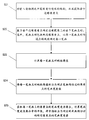
- FIG. 1 is a schematic flow chart of an embodiment of a method for detecting a component wrong component according to the present invention
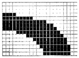
- FIG. 2 is a partial view showing a printed text on an image of an element to be detected of an embodiment of the method for detecting a defective component of the present invention
- step S2 is a schematic flow chart of step S2 of an embodiment of a method for detecting a component wrong component according to the present invention
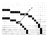
- FIG. 4 is a partial, fragmentary view showing a plurality of edge pixel points of an image of a component to be detected in an embodiment of a component error detecting method according to the present invention
- FIG. 5 is a view showing an example of repeatedly marking a stroke width value of a pixel of an image of a to-be-detected element according to an embodiment of the present invention
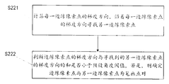
- step S22 is a schematic flow chart of step S22 of an embodiment provided by a component error detecting method according to the present invention.
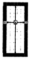
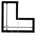
- Fig. 7 is a view showing an example of a stroke structure in which printed characters on an image of a member to be detected are present in an embodiment of the method for detecting a defective component of the present invention:
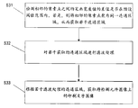
- FIG. 8 is a schematic flow chart of step S3 of an embodiment of a component error detecting method according to the present invention.
- step S4 is a schematic flow chart of step S4 of an embodiment of a method for detecting a component wrong component according to the present invention.
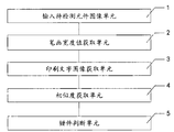
- Fig. 10 is a view showing the configuration of an embodiment of a component misdetecting device of the present invention.
- FIG. 1 is a schematic flowchart diagram of an embodiment of a method for detecting a component error component according to the present invention.
- the implementation specifically includes the following steps:
- step S3 of the embodiment of FIG. 2 it is further explained that the stroke width of the characters in the partial area is generally consistent; similarly, FIG. 2 is a partial example view of the printed characters on the image of the element to be detected; Printing The stroke width value of the text is usually consistent.
- the present embodiment uses the feature to detect a text area on the image of the component to be detected, thereby distinguishing the printed text on the image of the component to be detected from other scene elements.
- FIG. 3 is a schematic flowchart of step S2 of the embodiment.
- the step S2 of obtaining the stroke width value corresponding to each pixel point specifically includes the following steps:
- S21 Perform edge detection on the image of the input component to be detected, thereby acquiring a plurality of edge pixel points;
- FIG. 4 is a partial example view of inputting an image of a plurality of edge pixels to be detected by an image of a component to be detected.
- detecting an edge of the image of the input component to be detected uses a Canny edge detection operator to detect an image of the component to be detected.
- the edges to get a few edge pixels.
- the edge of an image refers to a dramatic change in the local characteristics of an image in a certain area, such as a sudden change in gray scale, a sudden change in color, and a sudden change in texture structure.
- the edge of the image is the most basic feature of the image and contains most of the information about the image. Since the Canny edge detection operator achieves a relatively good balance between image denoising and edge detail retention, and has the characteristics of simple implementation and fast processing speed, the embodiment preferably uses the edge detection algorithm to obtain the component to be detected. Edge pixel points.
- an edge pixel p of the example shown in FIG. 4 can find another edge pixel q, and the edge pixel point p and the edge pixel point q are end point segments for representing a stroke, edge pixels.
- Point p and edge pixel point q are a single point pair;
- the set of pixel points that pass from the edge pixel point m to the edge pixel point n is ⁇ m+1, m+2, . . . , n-2, n-1 ⁇ ; Any pixel in the set may be located on the stroke of the two stroke points.
- the stroke width of the two strokes is different, so that it is assigned twice in the labeling process. Taking pixel point k as an example, pixel point k is located at two
- the strokes are preferably applied to the strokes that are passed, and the solution is:
- the stroke width of the pixel point k is labeled as the distance value of the corresponding pair of stroke points, that is, the distance between the edge pixel point m and the edge pixel point n
- FIG. 6 is a schematic flowchart of step S22 of the embodiment, and step S22 specifically includes the following steps:
- S221 Calculate a gradient direction of each edge pixel, and search another edge pixel along a gradient direction of each edge pixel.
- step S2 further includes step S25, specifically:
- the pixel point j stores the stroke width of the two strokes in which the stroke is located.
- FIG. 8 is a schematic flowchart of step S3, and step S3 specifically includes the following steps:
- the stroke width of the text It can be seen from the stroke width of the text that the stroke width of the characters on the component to be detected is substantially the same. If the stroke widths of two adjacent pixels in the image of the component to be detected are similar, it is considered that the two pixels may belong to the same text. Should belong to the same connected area.
- the filtering processing method of step S32 preferably adopts the following methods:
- the variance of the stroke width value of each connected region is calculated, and if the variance of the stroke width value of the connected region is greater than the preset variance determination threshold, the connected region is discarded.
- the connected region of noise is determined by calculating the variance of the stroke width of each connected region, and is discarded as a connected region of noise.
- the width and height of each connected area are calculated, and if the width of the connected area exceeds a preset width range of the connected area, and/or the height of the connected area exceeds a preset height range of the connected area, the connected area is discarded.
- the printed characters on the element to be detected have a certain aspect ratio, it is possible to eliminate the too small and too large connected areas by defining the width and height of the connected areas for determining the text area.
- the obtained connected region is the text region of the component to be detected.
- FIG. 9 and FIG. 9 are schematic diagrams of the process of step S4, and step S4 specifically includes the following steps:
- S41 comparing the brightness of the printed image with the text template image, comparing the contrast of the image, and comparing the image structure, respectively obtaining brightness contrast values, contrast contrast values, and structural contrast values of the printed text image and the text template image.
- the similarity between the printed text image and the text template image is the structural similarity between the printed text image and the text template image, and the structural similarity is calculated by the following formula:
- SSIM (X, Y) represents structural similarity
- l (X, Y) represents brightness contrast value
- c (X, Y) represents contrast contrast value
- s (X, Y) represents structural contrast value
- ⁇ , ⁇ and ⁇ is a parameter for adjusting the relative importance of the brightness contrast value, the contrast contrast value, and the structure contrast value, respectively, and ⁇ >0, ⁇ >0, ⁇ >0.
- step S41 specifically, the brightness contrast value l(X, Y) of the printed text image and the text template image is obtained by calculating the following formula:
- ⁇ X represents the mean value of the printed character image
- ⁇ Y represents the mean value of the text template image
- C 1 is a constant, C 1 ⁇ 0;
- ⁇ X represents the standard deviation of the printed text image
- ⁇ Y represents the standard deviation of the text template image
- C 2 is a constant, C 2 ⁇ 0;
- step S41 specifically, the structural contrast value s(X, Y) of the printed text image and the text template image is obtained by calculating the following formula:
- ⁇ XY represents the covariance of the standard deviation of the printed character image and the text template image
- C 3 is a constant, C 3 ⁇ 0.
- the two image similarities can be calculated by calculating the structural similarity of the two images.
- the structural similarity includes measuring the similarity of images from three aspects: brightness, contrast and structure. Therefore, the present embodiment determines the similarity by comprehensively comparing the contrast values of the brightness, contrast, and structure of the printed character image and the text template image.
- the image of the component to be detected is input first, and then the stroke width value corresponding to each pixel on the image of the component to be detected is obtained; based on the approximate value of the stroke width value of the printed text on the component to be detected, corresponding to each pixel point
- the stroke width value of the stroke width is similar to the adjacent pixel points of the stroke width value, thereby obtaining a plurality of connected regions, and filtering the connected region to obtain a printed text image; finally, using the acquired printed text image and the preset Text template Comparing the three aspects of brightness, contrast and structure, and calculating the structural similarity between the printed text image and the text template image as three similar structures, the similarity is determined, and the component to be detected whose similarity is less than the preset threshold is determined as a wrong component.
- the extraction of the printed character image on the object to be detected is performed, thereby obtaining the printed text image; and the printed text image is compared with the preset text template image to determine the similarity with the template image.
- the lower component to be tested is a wrong piece.
- the invention realizes the positioning accuracy of the component text information is high based on the characteristics of the width of the text stroke, and is not easily interfered by the illumination, and solves the interference problem of the illumination on the detection component in the prior art, and the accuracy of detecting the wrong component of the component is greatly improved. Beneficial effect.
- FIG. 10 is a diagram showing an embodiment of a component error detecting device according to the present invention, including
- a stroke width value obtaining unit 2 configured to acquire a stroke width value corresponding to each pixel point on the image of the component to be detected
- the printed character image acquiring unit 3 is configured to obtain a printed character image on the image of the component to be detected according to the stroke width value corresponding to each pixel point;
- the similarity obtaining unit 4 is configured to compare the printed text image with the preset text template image, and calculate the similarity between the printed text image and the text template image;
- the wrong component determining unit 5 is configured to determine that the component to be detected is a wrong component when the similarity is less than a preset threshold.
- the image of the component to be detected is input by inputting the image unit 1 to be detected, and the image includes the printed text on the component to be detected; and then, the image of the image to be detected is acquired by the stroke width value acquiring unit 2 a stroke width value corresponding to a pixel, and determining, by the printed character image acquisition unit 3, a printed character image on the image of the component to be detected based on the acquired stroke width value; and then, by the similarity unit 4, the acquired printed character image and The preset text template images are compared to calculate the similarity; finally, the wrong component judging unit 5 judges whether the detecting component is a wrong component based on the similarity.
- the embodiment provided by the component wrong component detecting device of the present invention realizes high positioning accuracy of the component text information based on the characteristics of the character stroke width, is less susceptible to illumination interference, and greatly improves the accuracy of component misdetection detection.
Landscapes
- Engineering & Computer Science (AREA)
- Physics & Mathematics (AREA)
- General Physics & Mathematics (AREA)
- Theoretical Computer Science (AREA)
- Multimedia (AREA)
- Quality & Reliability (AREA)
- Computer Vision & Pattern Recognition (AREA)
- Image Analysis (AREA)
- Image Processing (AREA)
Abstract
一种元件错件检测方法及装置,其中,方法包括:输入待检测元件图像,其中,所述待检测元件图像包括所述待检测元件的印刷文字(S1);获取所述待检测元件图像上每一像素点对应的笔画宽度值(S2);根据所述每一像素点对应的笔画宽度值,获取所述待检测元件图像上的印刷文字图像(S3);将所述印刷文字图像与预设的文字模板图像进行对比,并计算所述印刷文字图像与所述文字模板图像的相似度(S4);当所述相似度小于预设阈值时,判断所述待检测元件为错件(S5)。所提供的元件错件检测方法和装置,能有效避免光照对检测元件文字时的干扰,提高元件错件检测结果的准确率。
Description
本发明涉及检测领域,尤其涉及一种元件错件检测方法和装置。
通常情况下,为了满足生产的需要,同种元件会有多种不同的型号,如电容等。为了方便区分不同型号的元件,需要在元件表面印刷相关的参数信息。为了保障电路板的质量,对元件上印刷文字进行检测,是自动光学检测(AOI)中一种常见的元件错件检测。
对元件上的印刷文字进行错件检测的系统主要包括两个部分:文字定位和文字对比。其中,文字定位起到了至关重要的作用。目前,文字定位算法主要采用了模板匹配的方法,即利用文字模板图在待检测图像中寻找与之最相近的位置。但是模板匹配算法容易受光照的影响,当光照发生较大的变化时,利用模板匹配算法得到的文字区域会发生较大的偏移,不利于后续文字对比或识别算法。
发明内容
本发明实施例的目的是提供一种元件错件检测方法和装置,能有效避免光照对检测元件文字时的干扰,提高元件错件检测结果的准确率。
为实现上述目的,本发明实施例提供了一种元件错件检测方法,包括:
输入待检测元件图像,其中,所述待检测元件图像包括所述待检测元件的印刷文字;
获取所述待检测元件图像上每一像素点对应的笔画宽度值;
根据所述每一像素点对应的笔画宽度值,获取所述待检测元件图像上的印刷文字图像;
将所述印刷文字图像与预设的文字模板图像进行对比,并计算所述印刷文字图像与所述文字模板图像的相似度;
当所述相似度小于预设阈值时,判断所述待检测元件为错件。
与现有技术相比,本发明提供的一种元件错件检测方法,基于文字笔画宽度的特性,实现对待检测元件上印刷文字图像的提取,从而获取印刷文字图像;并将印刷文字图像与预设的文字模板图像进行对比,判定与模板图像相比相似度较低的待检测元件为错件。本发明基
于文字笔画宽度的特性实现对元件文字信息的定位准确度高,不易受到光照干扰,解决了现有技术中光照对检测元件的干扰问题,获得了大大提高元件错件检测的准确度的有益效果。
进一步地,所述获取所述待检测元件的图像上每一像素点对应的笔画宽度值包括:
对所述输入待检测元件图像进行边缘的检测,从而获取若干边缘像素点;
基于所述若干边缘像素点确定所述边缘图像上的若干笔画点对;其中,所述笔画点对包括两边缘像素点,以所述每一笔画点对为端点的线段确定每一笔画;
计算每一所述笔画点对的距离值;
将每一所述笔画点对的距离值标注为对应所述笔画所经过的像素点的笔画宽度值。
作为本发明的进一步方案,通过获取所述待检测元件图像的边缘像素点,由确定为同一笔画点对的每两边缘像素点的距离对来计算笔画宽度值,对所述待检测元件图像的上同一笔画上的像素点标注对应的笔画宽度值;本技术方案只需要提取像素组的特征,不受限于水平方向的文字图像,计算简单,能够保证较高的精确度。
进一步地,所述基于所述若干边缘像素点确定所述边缘图像上的若干笔画点对包括:
计算每一所述边缘像素点的梯度方向,沿着每一所述边缘像素点的梯度方向寻找另一所述边缘像素点;
判断所述边缘像素点的梯度方向与所述寻找到的另一所述边缘像素点的梯度方向的和是否小于预设角度阈值,若是,则确定所述边缘像素点与另一所述边缘像素点为所述笔画点对。
进一步地,所述获取所述待检测元件的图像上每一像素点对应的笔画宽度值还包括:
获取每一所述笔画上的像素点的笔画宽度值集合,计算所述笔画宽度值集合中的中值,将所述中值标注为对应的所述笔画所经过的所有所述像素点的笔画宽度值。
进一步地,所述根据所述每一像素点对应的笔画宽度值,获取所述待检测元件图像上的印刷文字图像;包括:检测相邻的所述像素点之间的所述笔画宽度值的差值是否在预设阈值范围内,若是,则将所述相邻的像素点聚为同一连通区域,从而获取若干所述连通区域;
对若干获取的所述连通区域进行滤波处理;
根据若干滤波处理的所述连通区域,获取所述待检测元件图像上的所述印刷文字图像。
进一步地,所述对若干所述连通区域进行滤波处理包括:
计算每一所述连通区域的笔画宽度值的方差,若所述连通区域的笔画宽度的方差大于预
设方差判断阈值的,则抛弃所述连通区域。
作为本发明的进一步方案,由于文字的笔画宽度特征较为稳定、而噪声的波动较大,排除笔画宽度值的方差较大的连通区域可以排除噪声的干扰。
进一步地,所述对若干获取的所述连通区域进行滤波处理包括:
计算每一所述连通区域的宽度和高度,若所述连通区域的宽度超出连通区域的预设宽度范围,和/或所述连通区域的高度超出连通区域的预设高度范围,则抛弃所述连通区域。
作为本发明的进一步方案,在待检测元件上的印刷文字具有一定的宽高比例,可以定义用于获取印刷文字图像的连通区域的宽和高,排除过小和过大的连通区域。
进一步地,所述将所述印刷文字图像与预设的文字模板图像进行对比包括:
将所述印刷文字图像与所述文字模板图像进行图像亮度的对比、图像对比度的对比和图像结构的对比,并分别获取所述印刷文字图像与所述文字模板图像的亮度对比值、对比度对比值和结构对比值。
进一步地,所述印刷文字图像与所述文字模板图像的相似度为所述印刷文字图像与所述文字模板图像的结构相似性,所述结构相似性通过下述公式计算:
SSIM(X,Y)=[l(X,Y)]α·[c(X,Y)]β·[s(X,Y)]γ
其中,SSIM(X,Y)表示所述结构相似性;l(X,Y)表示所述亮度对比值,c(X,Y)表示所述对比度对比值;s(X,Y)表示所述结构对比值;α、β和γ分别为调整所述亮度对比值、所述对比度对比值和所述结构对比值的相对重要性的参数,且,α>0,β>0,γ>0。
进一步地,所述获取所述印刷文字图像与所述文字模板图像的亮度对比值包括:
通过计算下述公式获取所述印刷文字图像与所述文字模板图像的亮度对比值l(X,Y):

其中,μX表示所述印刷文字图像的均值;μY表示所述文字模板图像的均值;C1为常数,C1≠0;
所述获取所述印刷文字图像与所述文字模板图像的对比度对比值包括:
通过计算下述公式获取所述印刷文字图像与所述文字模板图像的对比度对比值c(X,Y):

其中,σX表示所述印刷文字图像的标准差;σY表示所述文字模板图像的标准差;C2为常数,C2≠0;
所述获取所述印刷文字图像与所述文字模板图像的结构对比值包括:
通过计算下述公式获取所述印刷文字图像与所述文字模板图像的结构对比值s(X,Y):

其中,σXY表示所述印刷文字图像的标准差与所述文字模板图像的协方差;C3为常数,C3≠0。
为实现本发明的目的,相应地,本发明还提供了一种元件错件检测装置,包括:
输入待检测元件图像单元,用于输入待检测元件图像,其中,所述待检测元件图像包括所述待检测元件的印刷文字;
笔画宽度值获取单元,用于获取所述待检测元件图像上每一像素点对应的笔画宽度值;
印刷文字图像获取单元,用于根据所述每一像素点对应的笔画宽度值,获取所述待检测元件图像上的印刷文字图像;
相似度获取单元,用于将所述印刷文字图像与预设的文字模板图像进行对比,并计算所述印刷文字图像与所述文字模板图像的相似度;
错件判断单元,用于当所述相似度小于预设阈值时,判断所述待检测元件为错件。与现有技术相比,本发明提供的一种元件错件检测装置,输入待检测元件图像,基于文字笔画宽度的特性,实现对待检测元件上印刷文字图像的提取,从而获取印刷文字图像;并将印刷文字图像与预设的文字模板图像进行对比,判定与模板图像相比相似度较低的待检测元件为错件。该装置基于文字笔画宽度的特性实现对元件文字信息的定位准确度高,不易受到光照干扰,解决了现有技术中光照对检测元件的干扰问题,获得了大大提高元件错件检测的准确度的有益效果。
图1是本发明一种元件错件检测方法提供的实施例的流程示意图;
图2是本发明一种元件错件检测方法提供的实施例的待检测元件图像上的印刷文字的局部示例图;
图3是本发明一种元件错件检测方法提供的实施例的步骤S2的流程示意图,
图4是本发明一种元件错件检测方法提供的实施例的待检测元件图像的若干边缘像素点的局部示例图;
图5是本发明一种元件错件检测方法提供的实施例的待检测元件图像的像素点被重复标注笔画宽度值的示例图;
图6本发明一种元件错件检测方法提供的实施例的步骤S22的流程示意图;
图7是本发明一种元件错件检测方法提供的实施例的待检测元件图像上的印刷文字存在的一种笔画结构的示例图:
图8是本发明一种元件错件检测方法提供的实施例的步骤S3的流程示意图;
图9是本发明一种元件错件检测方法提供的实施例的步骤S4的流程示意图;
图10是本发明一种元件错件检测装置提供的实施例的结构示意图。
下面将结合本发明实施例中的附图,对本发明实施例中的技术方案进行清楚、完整地描述,显然,所描述的实施例仅仅是本发明一部分实施例,而不是全部的实施例。基于本发明中的实施例,本领域普通技术人员在没有作出创造性劳动前提下所获得的所有其他实施例,都属于本发明保护的范围。
参见图1,图1是本发明一种元件错件检测方法提供的实施例的流程示意图,本实施具体包括以下步骤:
S1、输入待检测元件图像,其中,待检测元件图像包括待检测元件的印刷文字;
S2、获取待检测元件图像上每一像素点对应的笔画宽度值;
S3、根据每一像素点对应的笔画宽度值,获取待检测元件图像上的印刷文字图像;
S4、将印刷文字图像与预设的文字模板图像进行对比,并计算印刷文字图像与文字模板图像的相似度;
S5、当相似度小于预设阈值时,判断待检测元件为错件。
结合图2本实施例的步骤S3进行进一步说明:在局部区域内的文字的笔画宽度通常保持一致;同样地,图2为待检测元件图像上的印刷文字的局部示例图;在待检测元件上的印刷
文字的笔画宽度值通常是保持一致的。本实施例利用该特征检测待检测元件图像上的文字区域,从而使待检测元件图像上的印刷文字与其他场景元素区分开来。
结合图3,图3是本实施例步骤S2的流程示意图,获取每一像素点对应的笔画宽度值的步骤S2具体包括以下步骤:
S21、对输入待检测元件图像进行边缘的检测,从而获取若干边缘像素点;
参见图4,图4为输入待检测元件图像获取若干边缘像素点的局部示例图;优选地,本实施例中对输入待检测元件图像进行边缘的检测采用Canny边缘检测算子检测待检测元件图像的边缘,以获取若干边缘像素点。图像的边缘是指在某一区域内图像的局部特性发生了剧烈的变化,如灰度的突变、颜色的突变、纹理结构的突变等。图像的边缘是图像最基本的特征,包含了图像的大部分信息。由于Canny边缘检测算子在图像去噪和边缘细节保留上取得了相对较好的平衡,同时具有实现简单、处理速度快的特点,所以本实施例优选采用该边缘检测算法来获取待检测元件的边缘像素点。
S22、基于若干边缘像素点确定边缘图像上的若干笔画点对;其中,笔画点对包括两边缘像素点,以每一笔画点对为端点的线段确定每一笔画;
结合图4为例进行说明,图4中所示例的一边缘像素点p,可以找到另一边缘像素点q,边缘像素点p和边缘像素点q为端点的线段用于表示一笔画,边缘像素点p和边缘像素点q为一笔画点对;
S23、计算每一笔画点对的距离值;
结合图4为例进行说明,作为一笔画点对的边缘像素点p和边缘像素点q的距离值的计算公式:

其中,||p-q||表示边缘像素点p和边缘像素点q的距离值,xp,yp表示边缘点p在待检测元件图像中的坐标、xq,yq表示边缘像素点q在待检测元件图像中的坐标。
S24、将每一笔画点对的距离值标注为对应笔画所经过的像素点的笔画宽度值。
结合图5为例进行说明,假设从边缘像素点m到边缘像素点n所经过的像素点的集合为{m+1,m+2,...,n-2,n-1};对于该集合中任意像素点,可能位于两笔画点对所经过的笔画上,两笔画的笔画宽度不同,使得在标注过程中被两次赋值。以像素点k为例,像素点k位于两
笔画点对所经过的笔画,标注的过程中优选实施解决方式为:
若该像素点k从未赋值,则该像素点k的笔画宽度标注为对应的笔画点对的距离值,即边缘像素点m和边缘像素点n之间的距离||m-n||,其中, 若该像素点k已经赋值,则边缘像素点m和边缘像素点n之间的距离与当前已赋的笔画宽度值之间的较小值min(||m-n||,curVal)对应标注为该像素点k的笔画宽度,其中,curVal表示当前像素点k已赋的笔画宽度值。
结合图4和图6,图6是本实施例步骤S22的流程示意图,步骤S22具体包括以下步骤:
S221、计算每一边缘像素点的梯度方向,沿着每一边缘像素点的梯度方向寻找另一边缘像素点;
S222、判断边缘像素点的梯度方向与寻找到的另一边缘像素点的梯度方向的和是否小于预设角度阈值,若是,则确定边缘像素点与另一边缘像素点为笔画点对。
结合图4的边缘像素点p和边缘像素点q为例进行说明本实施例确定笔画点的实施过程:先计算边缘像素点p的梯度方向dp;梯度方向dp方向大致垂直于笔画的方向;然后沿着射线r=p+n*dp,n>0方向寻找,若能找到另外一个边缘像素点q被找到,边缘像素点q的梯度方向表示为dq;并且边缘像素点p的梯度方向dp和边缘像素点q的梯度方向dq的方向大致相反,满足边缘像素点p的梯度方向dp和边缘像素点q的梯度方向dq的和小于预设角度阈值,优选地,边缘像素点p和边缘像素点q满足公式 则边缘像素点p和边缘像素点q为所求的笔画点对。若找不到匹配的边缘像素点q,或者不满足边缘像素点p的梯度方向dp和边缘像素点q的梯度方向dq的和小于预设角度阈值的条件,则丢弃在该射线r。
在本实施例中,参见图3,步骤S2还包括步骤S25,具体:
S25、获取每一笔画上的像素点的笔画宽度值集合,计算笔画宽度值集合中的中值,将中值标注为对应的笔画所经过的所有像素点的笔画宽度值。
结合图7,通常情况下,字符中依然存在大量类似图7所示的笔画结构:以图中像素点j为例,经过步骤S24处理后,像素点j保存的是所在的两笔画的笔画宽度的较小值,但其并不是像素点j正确的笔画宽度,需要对其进行调整:对于像素点j所在的每一笔画,遍历通过的所有像素点所保存的笔画宽度得到集合{w1,w2,...,wn},计算集合{w1,w2,...,wn}的中值
wmid,mid<n,将这些像素点的笔画宽度赋值为wmid。
参见图8,图8为步骤S3的流程示意图,步骤S3具体包括以下步骤:
S31、检测相邻的像素点之间的笔画宽度值的差值是否在预设阈值范围内,若是,则将相邻的像素点聚为同一连通区域,从而获取若干连通区域;
由文字的笔画宽度可知,在待检测元件上的文字的笔画宽度基本一致,如果待检测元件图像中两相邻的像素点的笔画宽度大小相近,则认为两像素点有可能属于同一个文字,应该属于同一个连通区域。
S32、对若干获取的连通区域进行滤波处理;
S33、根据若干滤波处理的连通区域,获取待检测元件图像上的印刷文字图像。
其中,步骤S32的滤波处理方式优选采取以下方式:
优选地,计算每一连通区域的笔画宽度值的方差,若连通区域的笔画宽度值的方差大于预设方差判断阈值的,则抛弃连通区域。
由于文字的笔画宽度特征较为稳定,对应的笔画宽度值方差大;而噪声的波动较大,对应的笔画宽度值方差大。通过计算每个连通区域的笔画宽度的方差来确定为噪声的连通区域,抛弃为噪声的连通区域。
优选地,计算每一连通区域的宽度和高度,若连通区域的宽度超出连通区域的预设宽度范围,和/或连通区域的高度超出连通区域的预设高度范围,则抛弃该连通区域。
由于待检测元件上的印刷文字具有一定的宽高比例,所以可以通过定义用于确定文字区域的连通区域的宽和高,排除过小和过大的连通区域。
经过上述优选滤波处理方式处理后,得到的连通区域就是待检测元件的文字区域。
图9,图9为步骤S4的流程示意图,步骤S4具体包括以下步骤:
S41、将印刷文字图像与文字模板图像进行图像亮度的对比、图像对比度的对比和图像结构的对比,分别获取印刷文字图像与文字模板图像的亮度对比值、对比度对比值和结构对比值。
S42、印刷文字图像与文字模板图像的相似度为印刷文字图像与文字模板图像的结构相似性,结构相似性通过下述公式计算:
SSIM(X,Y)=[l(X,Y)]α·[c(X,Y)]β·[s(X,Y)]γ
其中,SSIM(X,Y)表示结构相似性;l(X,Y)表示亮度对比值,c(X,Y)表示对比度对比值;s(X,Y)表示结构对比值;α、β和γ分别为调整亮度对比值、对比度对比值和结构对比值的相对重要性的参数,且,α>0,β>0,γ>0。
在步骤S41中,具体地,通过计算下述公式获取印刷文字图像与文字模板图像的亮度对比值l(X,Y):
其中,μX表示印刷文字图像的均值;μY表示文字模板图像的均值;C1为常数,C1≠0;


其中,σX表示印刷文字图像的标准差;σY表示文字模板图像的标准差;C2为常数,C2≠0;
在步骤S41中,具体地,通过计算下述公式获取印刷文字图像与文字模板图像的结构对比值s(X,Y):

其中,σXY表示印刷文字图像的标准差与文字模板图像的协方差;C3为常数,C3≠0。
其中,C1、C2、C3用于避免分母为0的情况;优选地,取C1=(K1*L)2,C2=(K2*L)2,C3=C2/2,其中K1=0.01,K2=0.03,L=255。
通常地,两幅图像相似度可以通过计算两幅图像的结构相似性作为衡量的指标,结构相似性包括从亮度、对比度和结构三个方面度量图像的相似性。所以本实施例通过综合对比印刷文字图像和文字模板图像的亮度、对比度和结构的对比值来确定相似度。
具体实施时,先输入待检测元件图像,然后获取待检测元件图像上每一像素点对应的笔画宽度值;基于待检测元件上的印刷文字的笔画宽度值近似的基础,根据每一像素点对应的笔画宽度值将相近笔画宽度值的相邻像素点类聚成,从而获取若干连通区域,并对连通区域进行滤波处理后,以获取印刷文字图像;最后利用获取的印刷文字图像与预设的文字模板图
像从亮度、对比度和结构三个方面进行对比,并以三个对比结构计算印刷文字图像与文字模板图像的结构相似性作为相似度,判断相似度小于预设阈值的待检测元件为错件。
本实施例基于文字笔画宽度的特性,实现对待检测元件上印刷文字图像的提取,从而获取印刷文字图像;并将印刷文字图像与预设的文字模板图像进行对比,判定与模板图像相比相似度较低的待检测元件为错件。本发明基于文字笔画宽度的特性实现对元件文字信息的定位准确度高,不易受到光照干扰,解决了现有技术中光照对检测元件的干扰问题,获得了大大提高元件错件检测的准确度的有益效果。
参见图10,图10是本发明一种元件错件检测装置提供的实施例,包括
输入待检测元件图像单元1,用于输入待检测元件图像,其中,待检测元件图像包括待检测元件的印刷文字;
笔画宽度值获取单元2,用于获取待检测元件图像上每一像素点对应的笔画宽度值;
印刷文字图像获取单元3,用于根据每一像素点对应的笔画宽度值,获取待检测元件图像上的印刷文字图像;
相似度获取单元4,用于将印刷文字图像与预设的文字模板图像进行对比,并计算印刷文字图像与文字模板图像的相似度;
错件判断单元5,用于当相似度小于预设阈值时,判断待检测元件为错件。
具体实施时,先通过输入待检测元件图像单元1输入待检测元件图像,该图像包括了待检测元件上的印刷文字;接着,通过笔画宽度值获取单元2获取输入的待检测元件图像上的每一像素点对应的笔画宽度值,并通过印刷文字图像获取单元3基于获取的笔画宽度值,来确定待检测元件图像上的印刷文字图像;然后,通过相似度单元4对获取的印刷文字图像和预设的文字模板图像进行对比,以计算相似度;最后通过错件判断单元5根据相似度来判断检测元件是否为错件。
本发明一种元件错件检测装置提供的实施例,基于文字笔画宽度的特性实现对元件文字信息的定位准确度高,不易受到光照干扰,大大提高元件错件检测的准确度。
以上所述是本发明的优选实施方式,应当指出,对于本技术领域的普通技术人员来说,在不脱离本发明原理的前提下,还可以做出若干改进,这些改进也视为本发明的保护范围。
Claims (11)
- 一种元件错件检测方法,其特征在于,包括:输入待检测元件图像,其中,所述待检测元件图像包括所述待检测元件的印刷文字;获取所述待检测元件图像上每一像素点对应的笔画宽度值;根据所述每一像素点对应的笔画宽度值,获取所述待检测元件图像上的印刷文字图像;将所述印刷文字图像与预设的文字模板图像进行对比,并计算所述印刷文字图像与所述文字模板图像的相似度;当所述相似度小于预设阈值时,判断所述待检测元件为错件。
- 如权利要求1所述的一种元件错件检测方法,其特征在于,所述获取所述待检测元件的图像上每一像素点对应的笔画宽度值包括:对所述输入待检测元件图像进行边缘的检测,从而获取若干边缘像素点;基于所述若干边缘像素点确定所述边缘图像上的若干笔画点对;其中,所述笔画点对包括两边缘像素点,以所述每一笔画点对为端点的线段确定每一笔画;计算每一所述笔画点对的距离值;将每一所述笔画点对的距离值标注为对应所述笔画所经过的像素点的笔画宽度值。
- 如权利要求2所述的一种元件错件检测方法,其特征在于,所述基于所述若干边缘像素点确定所述边缘图像上的若干笔画点对包括:计算每一所述边缘像素点的梯度方向,沿着每一所述边缘像素点的梯度方向寻找另一所述边缘像素点;判断所述边缘像素点的梯度方向与所述寻找到的另一所述边缘像素点的梯度方向的和是否小于预设角度阈值,若是,则确定所述边缘像素点与另一所述边缘像素点为所述笔画点对。
- 如权利要求2所述的一种元件错件检测方法,其特征在于,所述获取所述待检测元件的图像上每一像素点对应的笔画宽度值还包括:获取每一所述笔画上的像素点的笔画宽度值集合,计算所述笔画宽度值集合中的中值,将所述中值标注为对应的所述笔画所经过的所有所述像素点的笔画宽度值。
- 如权利要求1所述的一种元件错件检测方法,其特征在于,所述根据所述每一像素点对应的笔画宽度值,获取所述待检测元件图像上的印刷文字图像;包括:检测相邻的所述像素点之间的所述笔画宽度值的差值是否在预设阈值范围内,若是,则将所述相邻的像素点聚为同一连通区域,从而获取若干所述连通区域;对若干获取的所述连通区域进行滤波处理;根据若干滤波处理的所述连通区域,获取所述待检测元件图像上的所述印刷文字图像。
- 如权利要求5所述的一种元件错件检测方法,其特征在于,所述对若干所述连通区域进行滤波处理包括:计算每一所述连通区域的笔画宽度值的方差,若所述连通区域的笔画宽度的方差大于预设方差判断阈值的,则抛弃所述连通区域。
- 如权利要求5所述的一种元件错件检测方法,其特征在于,所述对若干获取的所述连通区域进行滤波处理包括:计算每一所述连通区域的宽度和高度,若所述连通区域的宽度超出连通区域的预设宽度范围,和/或所述连通区域的高度超出连通区域的预设高度范围,则抛弃所述连通区域。
- 如权利要求1所述的一种元件错件检测方法,其特征在于,所述将所述印刷文字图像与预设的文字模板图像进行对比包括:将所述印刷文字图像与所述文字模板图像进行图像亮度的对比、图像对比度的对比和图像结构的对比,并分别获取所述印刷文字图像与所述文字模板图像的亮度对比值、对比度对比值和结构对比值。
- 如权利要求8所述的一种元件错件检测方法,其特征在于,所述印刷文字图像与所述文字模板图像的相似度为所述印刷文字图像与所述文字模板图像的结构相似性,所述结构相 似性通过下述公式计算:SSIM(X,Y)=[l(X,Y)]α·[c(X,Y)]β·[s(X,Y)]γ其中,SSIM(X,Y)表示所述结构相似性;l(X,Y)表示所述亮度对比值,c(X,Y)表示所述对比度对比值;s(X,Y)表示所述结构对比值;α、β和γ分别为调整所述亮度对比值、所述对比度对比值和所述结构对比值的相对重要性的参数,且,α>0,β>0,γ>0。
- 如权利要求9所述的一种元件错件检测方法,其特征在于,所述获取所述印刷文字图像与所述文字模板图像的亮度对比值包括:通过计算下述公式获取所述印刷文字图像与所述文字模板图像的亮度对比值l(X,Y):
 其中,μX表示所述印刷文字图像的均值;μY表示所述文字模板图像的均值;C1为常数,C1≠0;所述获取所述印刷文字图像与所述文字模板图像的对比度对比值包括:通过计算下述公式获取所述印刷文字图像与所述文字模板图像的对比度对比值c(X,Y):
 其中,σX表示所述印刷文字图像的标准差;σY表示所述文字模板图像的标准差;C2为常数,C2≠0;所述获取所述印刷文字图像与所述文字模板图像的结构对比值包括:通过计算下述公式获取所述印刷文字图像与所述文字模板图像的结构对比值s(X,Y):
 其中,σXY表示所述印刷文字图像的标准差与所述文字模板图像的协方差;C3为常数,C3≠0。
 - 一种元件错件检测装置,其特征在于,包括输入待检测元件图像单元,用于输入待检测元件图像,其中,所述待检测元件图像包括所述待检测元件的印刷文字;笔画宽度值获取单元,用于获取所述待检测元件图像上每一像素点对应的笔画宽度值;印刷文字图像获取单元,用于根据所述每一像素点对应的笔画宽度值,获取所述待检测元件图像上的印刷文字图像;相似度获取单元,用于将所述印刷文字图像与预设的文字模板图像进行对比,并计算所述印刷文字图像与所述文字模板图像的相似度;错件判断单元,用于当所述相似度小于预设阈值时,判断所述待检测元件为错件。
Applications Claiming Priority (2)
| Application Number | Priority Date | Filing Date | Title |
|---|---|---|---|
| CN201610906871.9A CN106485710A (zh) | 2016-10-18 | 2016-10-18 | 一种元件错件检测方法和装置 |
| CN201610906871.9 | 2016-10-18 |
Publications (1)
| Publication Number | Publication Date |
|---|---|
| WO2018072333A1 true WO2018072333A1 (zh) | 2018-04-26 |
Family
ID=58270159
Family Applications (1)
| Application Number | Title | Priority Date | Filing Date |
|---|---|---|---|
| PCT/CN2016/113596 Ceased WO2018072333A1 (zh) | 2016-10-18 | 2016-12-30 | 一种元件错件检测方法和装置 |
Country Status (2)
| Country | Link |
|---|---|
| CN (1) | CN106485710A (zh) |
| WO (1) | WO2018072333A1 (zh) |
Cited By (5)
| Publication number | Priority date | Publication date | Assignee | Title |
|---|---|---|---|---|
| CN110148147A (zh) * | 2018-11-07 | 2019-08-20 | 腾讯大地通途(北京)科技有限公司 | 图像检测方法、装置、存储介质和电子装置 |
| CN110766095A (zh) * | 2019-11-01 | 2020-02-07 | 易思维(杭州)科技有限公司 | 基于图像灰度特征的缺陷检测方法 |
| CN111325199A (zh) * | 2018-12-14 | 2020-06-23 | 中移(杭州)信息技术有限公司 | 一种文字倾斜角度检测方法及装置 |
| CN114187267A (zh) * | 2021-12-13 | 2022-03-15 | 沭阳县苏鑫冲压件有限公司 | 基于机器视觉的冲压件缺陷检测方法 |
| CN118587436A (zh) * | 2024-05-21 | 2024-09-03 | 广东弗我智能制造有限公司 | 用于电子烟组装零部件的识别方法及系统 |
Families Citing this family (3)
| Publication number | Priority date | Publication date | Assignee | Title |
|---|---|---|---|---|
| CN108573251B (zh) * | 2017-03-15 | 2021-09-07 | 北京京东尚科信息技术有限公司 | 文字区域定位方法和装置 |
| CN112435222A (zh) * | 2020-11-11 | 2021-03-02 | 深圳技术大学 | 一种电路板检测方法、装置及计算机可读存储介质 |
| CN115661183B (zh) * | 2022-12-27 | 2023-03-21 | 南京功夫豆信息科技有限公司 | 一种基于边缘计算的智能扫描管理系统及方法 |
Citations (4)
| Publication number | Priority date | Publication date | Assignee | Title |
|---|---|---|---|---|
| US20070116360A1 (en) * | 2005-11-21 | 2007-05-24 | Samsung Electronics Co., Ltd. | Apparatus and method for detecting character region in image |
| CN101666761A (zh) * | 2009-10-26 | 2010-03-10 | 北京星河泰视特科技有限公司 | Aoi免编程检测方法 |
| CN104794479A (zh) * | 2014-01-20 | 2015-07-22 | 北京大学 | 基于局部笔画宽度变换的自然场景图片中文本检测方法 |
| CN105389818A (zh) * | 2015-11-12 | 2016-03-09 | 广州视源电子科技股份有限公司 | 元件的定位方法和系统 |
Family Cites Families (2)
| Publication number | Priority date | Publication date | Assignee | Title |
|---|---|---|---|---|
| CN105046271B (zh) * | 2015-06-25 | 2018-03-30 | 哈尔滨工业大学 | 基于模板匹配的melf元件定位与检测方法 |
| CN105630751A (zh) * | 2015-12-28 | 2016-06-01 | 厦门优芽网络科技有限公司 | 一种快速比对文本内容的方法与系统 |
-
2016
- 2016-10-18 CN CN201610906871.9A patent/CN106485710A/zh active Pending
- 2016-12-30 WO PCT/CN2016/113596 patent/WO2018072333A1/zh not_active Ceased
Patent Citations (4)
| Publication number | Priority date | Publication date | Assignee | Title |
|---|---|---|---|---|
| US20070116360A1 (en) * | 2005-11-21 | 2007-05-24 | Samsung Electronics Co., Ltd. | Apparatus and method for detecting character region in image |
| CN101666761A (zh) * | 2009-10-26 | 2010-03-10 | 北京星河泰视特科技有限公司 | Aoi免编程检测方法 |
| CN104794479A (zh) * | 2014-01-20 | 2015-07-22 | 北京大学 | 基于局部笔画宽度变换的自然场景图片中文本检测方法 |
| CN105389818A (zh) * | 2015-11-12 | 2016-03-09 | 广州视源电子科技股份有限公司 | 元件的定位方法和系统 |
Cited By (9)
| Publication number | Priority date | Publication date | Assignee | Title |
|---|---|---|---|---|
| CN110148147A (zh) * | 2018-11-07 | 2019-08-20 | 腾讯大地通途(北京)科技有限公司 | 图像检测方法、装置、存储介质和电子装置 |
| CN110148147B (zh) * | 2018-11-07 | 2024-02-09 | 腾讯大地通途(北京)科技有限公司 | 图像检测方法、装置、存储介质和电子装置 |
| CN111325199A (zh) * | 2018-12-14 | 2020-06-23 | 中移(杭州)信息技术有限公司 | 一种文字倾斜角度检测方法及装置 |
| CN111325199B (zh) * | 2018-12-14 | 2023-10-27 | 中移(杭州)信息技术有限公司 | 一种文字倾斜角度检测方法及装置 |
| CN110766095A (zh) * | 2019-11-01 | 2020-02-07 | 易思维(杭州)科技有限公司 | 基于图像灰度特征的缺陷检测方法 |
| CN110766095B (zh) * | 2019-11-01 | 2022-04-19 | 易思维(杭州)科技有限公司 | 基于图像灰度特征的缺陷检测方法 |
| CN114187267A (zh) * | 2021-12-13 | 2022-03-15 | 沭阳县苏鑫冲压件有限公司 | 基于机器视觉的冲压件缺陷检测方法 |
| CN114187267B (zh) * | 2021-12-13 | 2023-07-21 | 沭阳县苏鑫冲压件有限公司 | 基于机器视觉的冲压件缺陷检测方法 |
| CN118587436A (zh) * | 2024-05-21 | 2024-09-03 | 广东弗我智能制造有限公司 | 用于电子烟组装零部件的识别方法及系统 |
Also Published As
| Publication number | Publication date |
|---|---|
| CN106485710A (zh) | 2017-03-08 |
Similar Documents
| Publication | Publication Date | Title |
|---|---|---|
| WO2018072333A1 (zh) | 一种元件错件检测方法和装置 | |
| CN111474184B (zh) | 基于工业机器视觉的aoi字符缺陷检测方法和装置 | |
| CN109816673B (zh) | 一种非极大值抑制、动态阈值计算及图像边缘检测方法 | |
| CN115861291B (zh) | 基于机器视觉的贴片电路板生产缺陷检测方法 | |
| CN107424160B (zh) | 通过视觉系统查找图像中线的系统和方法 | |
| CN110047063B (zh) | 一种物料掉落的检测方法、装置、设备及存储介质 | |
| WO2018209941A1 (zh) | 一种基于高斯拟合的高密度电路板圆孔亚像素检测方法 | |
| CN111340749B (zh) | 图像质量的检测方法、装置、设备及存储介质 | |
| CN104732207B (zh) | 高精度与高抗干扰性定位PCB板Mark点的方法及装置 | |
| CN113393447B (zh) | 基于深度学习的针尖正位度检测方法及系统 | |
| CN114022439B (zh) | 一种基于形态学图像处理的柔性电路板缺陷检测方法 | |
| CN110929720B (zh) | 一种基于logo匹配和ocr的元器件检测方法 | |
| CN105279772B (zh) | 一种红外序列图像的可跟踪性判别方法 | |
| CN105718931B (zh) | 用于确定采集图像中的杂斑的系统和方法 | |
| WO2017181724A1 (zh) | 电子元件漏件检测方法和系统 | |
| CN112419225B (zh) | 一种基于引脚分割的sop型芯片检测方法及系统 | |
| CN114627080B (zh) | 基于计算机视觉的车辆冲压配件缺陷检测方法 | |
| CN106340010B (zh) | 一种基于二阶轮廓差分的角点检测方法 | |
| CN112419260A (zh) | 一种pcb文字区域缺陷检测方法 | |
| CN114549400A (zh) | 一种图像识别方法及装置 | |
| CN111667429B (zh) | 一种巡检机器人目标定位校正方法 | |
| CN106778813A (zh) | 深度图像的自适应聚类分割算法 | |
| Zhang et al. | A new algorithm for accurate and automatic chessboard corner detection | |
| CN106530273B (zh) | 高精度fpc直线线路检测与缺陷定位方法 | |
| Babbar et al. | Comparative study of image matching algorithms |
Legal Events
| Date | Code | Title | Description |
|---|---|---|---|
| 121 | Ep: the epo has been informed by wipo that ep was designated in this application |
Ref document number: 16919293 Country of ref document: EP Kind code of ref document: A1 |
|
| NENP | Non-entry into the national phase |
Ref country code: DE |
|
| 32PN | Ep: public notification in the ep bulletin as address of the adressee cannot be established |
Free format text: NOTING OF LOSS OF RIGHTS PURSUANT TO RULE 112(1) EPC (EPO FORM 1205A DATED 08.10.2019) |
|
| 122 | Ep: pct application non-entry in european phase |
Ref document number: 16919293 Country of ref document: EP Kind code of ref document: A1 |