WO2018046950A1 - Product assembly systems - Google Patents
Product assembly systems Download PDFInfo
- Publication number
- WO2018046950A1 WO2018046950A1 PCT/GB2017/052641 GB2017052641W WO2018046950A1 WO 2018046950 A1 WO2018046950 A1 WO 2018046950A1 GB 2017052641 W GB2017052641 W GB 2017052641W WO 2018046950 A1 WO2018046950 A1 WO 2018046950A1
- Authority
- WO
- WIPO (PCT)
- Prior art keywords
- profile
- nominal
- variation
- product
- control parameters
- Prior art date
- Legal status (The legal status is an assumption and is not a legal conclusion. Google has not performed a legal analysis and makes no representation as to the accuracy of the status listed.)
- Ceased
Links
Classifications
-
- G—PHYSICS
- G05—CONTROLLING; REGULATING
- G05B—CONTROL OR REGULATING SYSTEMS IN GENERAL; FUNCTIONAL ELEMENTS OF SUCH SYSTEMS; MONITORING OR TESTING ARRANGEMENTS FOR SUCH SYSTEMS OR ELEMENTS
- G05B19/00—Program-control systems
- G05B19/02—Program-control systems electric
- G05B19/418—Total factory control, i.e. centrally controlling a plurality of machines, e.g. direct or distributed numerical control [DNC], flexible manufacturing systems [FMS], integrated manufacturing systems [IMS] or computer integrated manufacturing [CIM]
- G05B19/41805—Total factory control, i.e. centrally controlling a plurality of machines, e.g. direct or distributed numerical control [DNC], flexible manufacturing systems [FMS], integrated manufacturing systems [IMS] or computer integrated manufacturing [CIM] characterised by assembly
-
- G—PHYSICS
- G05—CONTROLLING; REGULATING
- G05B—CONTROL OR REGULATING SYSTEMS IN GENERAL; FUNCTIONAL ELEMENTS OF SUCH SYSTEMS; MONITORING OR TESTING ARRANGEMENTS FOR SUCH SYSTEMS OR ELEMENTS
- G05B2219/00—Program-control systems
- G05B2219/30—Nc systems
- G05B2219/31—From computer integrated manufacturing till monitoring
- G05B2219/31034—Component identifier and location indicator corresponding to component
-
- G—PHYSICS
- G05—CONTROLLING; REGULATING
- G05B—CONTROL OR REGULATING SYSTEMS IN GENERAL; FUNCTIONAL ELEMENTS OF SUCH SYSTEMS; MONITORING OR TESTING ARRANGEMENTS FOR SUCH SYSTEMS OR ELEMENTS
- G05B2219/00—Program-control systems
- G05B2219/30—Nc systems
- G05B2219/37—Measurements
- G05B2219/37207—Verify, probe, workpiece
-
- Y—GENERAL TAGGING OF NEW TECHNOLOGICAL DEVELOPMENTS; GENERAL TAGGING OF CROSS-SECTIONAL TECHNOLOGIES SPANNING OVER SEVERAL SECTIONS OF THE IPC; TECHNICAL SUBJECTS COVERED BY FORMER USPC CROSS-REFERENCE ART COLLECTIONS [XRACs] AND DIGESTS
- Y02—TECHNOLOGIES OR APPLICATIONS FOR MITIGATION OR ADAPTATION AGAINST CLIMATE CHANGE
- Y02P—CLIMATE CHANGE MITIGATION TECHNOLOGIES IN THE PRODUCTION OR PROCESSING OF GOODS
- Y02P90/00—Enabling technologies with a potential contribution to greenhouse gas [GHG] emissions mitigation
- Y02P90/02—Total factory control, e.g. smart factories, flexible manufacturing systems [FMS] or integrated manufacturing systems [IMS]
Definitions
- the present invention is related to a method and system of assembly of manufactured products, and more specifically, although not exclusively, to methods/systems for controlling or implementing assembly processes.
- a large proportion of rejected manufactured products are related to geometric or dimensional variation in the product, arising from fixtures and tools used in the manufacturing process.
- design changes are related to dimensional variation of the parts to be used in assembly of the product. For example, during the design of a single closure panel fixture around a hundred engineering changes may be required to be made after design release. These changes can include adding new design features, moving or changing fixture locators, or modifying part flanges, etc. For each of these changes the fixture design has to be revised, verified and validated and finally the design needs to be updated.
- Variations in products arising from process-related and product-related variations is a critical barrier to the delivery of high quality products.
- the optimization algorithms can localize fixtures at any continuous position over the geometric space, but the mesh model only has defined some discrete position over the part surface. Therefore, a re-meshing algorithm is necessary to redefine the nodes so that the fixtures can be located in the model.
- this approach is time consuming especially when significant numbers, e.g. hundreds or thousands of simulations, may be required to reach the optimum solution.
- a product assembly process for product manufacture comprising measuring a geometric profile of a part, calculating variation in the measured profile of the part from a nominal profile of the part, determining locations of physical constraints on the measured profile caused by a member adjacent to the part during the assembly process, identifying a set of control parameters that characterise a control scheme, wherein a nominal control scheme for assembly of the nominal profile of the part comprises a set of nominal control parameters, generating a variation response function based on the calculated variation and locations of physical constraints, and modifying the set of nominal control parameters so as to output a modified set of control parameters based on the variation response function.
- the invention may thus allow use of the modified set of control parameters to control product assembly.
- the method may comprise a method of initialisation of a product assembly process, for example in which the product assembly process is initiated, or a product assembly control scheme implemented, based on the modified control parameter values.
- a system for implementing an assembly process for product manufacture comprising a scanner for measuring a geometric profile of a part, a comparator for calculating variation in the measured profile of the part from a nominal profile of the part and for determining locations of physical constraints on the measured profile caused by a member adjacent to the part during the assembly process, an evaluator for identifying a set of control parameters that characterise a control scheme, wherein a nominal control scheme for assembly of the nominal profile of the part comprises a set of nominal control parameters, the evaluator arranged to generate a variation response function, and an assembly process modifier for modifying the set of control parameter values away from the nominal control parameters based on the variation response function.
- the part may be a three-dimensional part.
- the part may comprise a plurality of surface portions at different angular orientations, such as for example straight and/or curved surface portions.
- the part may comprise a complex and/or convoluted surface.
- the part may comprise a sheet material, e.g. metal, part.
- the adjacent member may comprise a fixture or adjacent part in the assembly.
- the fixture may comprise a clamp, support, abutment or the like.
- a set of part/product characteristics and control characteristics may characterise an assembly process.
- a set of part/product characteristics may comprise geometric
- Each part/product characteristic may comprise any or any combination of a location, size/dimension and/or orientation of a geometric feature of the part.
- the part/product characteristics may include part features, such as openings, slots, recesses, projections, wall thickness, edge features or the like. It is beneficial for the part/product characteristics to be controlled within design specifications in order to ensure that the assembled product meets
- control characteristics may be designed to satisfy the product characteristics.
- Each product characteristic may have a tolerance range or threshold associated therewith, e.g. defining an acceptable range of deviation from a nominal characteristic value.
- the nominal profile may be comprised in a nominal profile model for the part.
- the nominal model may comprise a geometric definition of the nominal profile and one or more design constraint.
- Design constraints may comprise the tolerance range(s) for any, any combination, or all, of the product characteristics of the nominal profile. Additionally or alternatively, design constraints may comprise limits or thresholds on any part parameter, such as an engineering parameter. Examples may include part dimensions, envelope, wall thickness, weight distribution, feature location or the like.
- a subset of the product characteristics or the control characteristics may correspond to final product characteristics or control characteristics being delivered during a design stage of product manufacture. This subset may correspond to a final set of parameters delivered by a design process.
- Design constraints may act on a specific task.
- Design constraints may include model accuracy/tolerance, computational time and/or technological constraints.
- a design task may link product characteristics to control characteristics, and may take into consideration design constraints.
- a design task may link generic characteristics to generic control characteristics/parameters.
- a design task may deliver modified/refined sets of product characteristics and/or control
- a remote laser welding joining process it may be intended to design and/or optimise a joint layout (a product characteristic) for a given clamp layout (a control characteristic) and initial joint layout as per designer experience.
- a joint layout a product characteristic
- a control characteristic a control characteristic
- initial joint layout a joint layout for a given clamp layout
- initial joint layout a control characteristic
- optimise clamp layout and joint quality simultaneously in a remote laser welding assembly process.
- the design task may comprise a mathematical relationship defining the control parameters in dependence upon the product characteristics, e.g. as a feedforward analysis.
- a feed-back analysis may be used to re-define the product characteristics according to the modified/refined control characteristics or parameters.
- the variation response function may include a part variation mechanistic model, which may include part compliancy.
- the variation response function may include a part-to-part interaction model.
- the variation response function may include an adjacent member, e.g. fixture or tooling, mechanistic model.
- the variation response function may include a part to fixture interaction model and/or a fixture to joint interaction model.
- a physical constraint on the part profile due to the adjacent member may limit the available variation of the part at the location of the physical constraint.
- the variation response function may be a multi-dimensional function, and may represent single or multiple product characteristics and/or control characteristics.
- the nominal part profile may be provided as CAD data, e.g. providing product specifications.
- the nominal part profile may comprise one or more join/assembly location and or dimension, such as a joint length and/or spacing.
- the nominal part profile may include a join/weld stitch pattern and/or material stack up specifications.
- Product specifications of the nominal part profile may correspond to refined product characteristics, e.g. as refined by the design task.
- the nominal control scheme may be provided from CAD data, providing process specifications.
- the nominal control scheme may include locator strategy, clamp location and/or number of clamps.
- Process specifications may correspond to refined control characteristics, e.g. as refined by the design task.
- Measuring a geometric profile of a part may comprise measuring a set of points on the product through a Coordinate Measurement Machine devices or an optical scanner.
- a non-contact profile measuring device may be used.
- Calculating variation of the profile of the part from a nominal profile of the part may comprise implementation of a part variation modeller.
- the part variation modeller may parametrise part error deviation by a limited set of main
- the part error deviation may be the composition of size, orientation, position and/or shape errors.
- Determining the locations of physical constraints on the profile of the part caused by an adjacent member during the assembly process may comprise
- the fixture modeller may provide libraries for simulating fixture constraints.
- the fixture modeller may account for flexibility of parts.
- the adjacent member may be a clamping tool or pin/slot locator.
- the fixture modeller may model part-to-part interaction by imposing constraints at a part-to-part interface to avoid part-to-part penetrations. It is beneficial to model part-to-part interaction in some specific joining processes, for example in remote laser welding, it is advantageous to simulate the part fitting in order to evaluate the part-to-part gap, which may strongly affect the overall quality of the joint.
- the part variation modeller and fixture modeller may simulate an assembly joining process for a given set of product characteristics and/or control characteristics.
- the nominal profile of the part may be represented by a mesh.
- the mesh may be represented as a set of vertices connected by quadrilateral elements or triangular elements. Surface deviations may be calculated for every vertex of the mesh. Mapping a deviation field on nominal mesh geometry may provide a 3D
- a deviation at a given point may be a linear composition of the part error deviation and the elastic displacement due to part flexibility.
- the part variation modeller may determine the part error deviation at a vertex, whereas the fixture model may calculate the deviation component related to part flexibility due to forces or displacements induced by clamps and/or tools.
- the deviation field may be separated into a set of orthogonal and independent deformation modes. Part error deviation may be obtained as a linear combination of a set of deformation modes. Deformation modes may be calculated by decomposing the deviation field. Discrete Cosine Transform may be used.
- Calculation of the deformation modes may comprise calculating the deviation for every vertex of the nominal mesh geometry and enveloping the nominal mesh geometry into a 3D regular voxel grid, wherein for each voxel containing a mesh vertex, the related deviation is stored in.
- a laplacian smoothing operation may be applied to smooth the voxel model and make a continuous data field. The laplacian smoothing operation may assign meaningful value in empty voxel elements, keeping the original deviation as internal boundary conditions.
- Most significant modes may be extracted. The most significant modes may be extracted using an energy compaction criterion, wherein each deformation mode is parametrised by means of its related Discrete Cosine Transform coefficient, and the related weight, which may correspond to a magnitude of the deformation mode.
- the fixture modeller may evaluate elastic displacement due to part flexibility, when parts are loaded and clamped onto a fixture.
- the elastic displacement may be modelled based on a Finite Element Analysis formulation. Triangular and quadrilateral elements may be modelled as shell elements, having membrane and bending behaviour.
- the shell elements may be separated into a membrane element (in-plane) and a plate bending part (out-of-plane). In-plane and out-of- plane behaviours may be decoupled, however, may become dependent for non- planar quadrilateral elements.
- Fixtures and tools may be treated as boundary constraints to be applied on a nominal or non-ideal part geometry.
- Bilateral constraints may define bilateral restraining conditions, which may be suitable for modelling pin/hole or pin/slot locator layouts.
- Unilateral constraints may be used to model clamp tools or resting locators.
- the fixture modeller may evaluate contact pairs. This may be useful for avoiding part-to-part penetration during assembly loading, fasting or part re-positioning.
- Generating the variation response function may comprise evaluating input parameters of product characteristics and/or control characteristics and refined parameters of product characteristics and/or control characteristics, as output by the part generation modeller and fixture modeller.
- An adaptive technique may be utilised to refine the generated variation response function. For example, Lipschitz adaptive sampling may be used to add sample points where derivatives exhibit highest variations.
- Modifying the set of control parameter values away from the nominal control parameters based on the variation response function may comprise feed-back synthesis.
- Feed-back synthesis may comprise assigning a set of product characteristics and control characteristics, and evaluating a refined set of product characteristics and control characteristics subject to design constraints.
- Feedback synthesis may comprise repeating assigning a set of product characteristics and control characteristics and evaluating a refined set of product characteristics and control characteristics until reaching a required level of convergence of the solution.
- the assigned set of product characteristics and control characteristics may be assigned by a design synthesis process, for example a process optimiser.
- the method of implementing an assembly process for product manufacture may comprise feed-forward analysis.
- Feed forward analysis may comprise assigning a set of product characteristics and control characteristics, and evaluating a refined set of product characteristics and control characteristics.
- the refined set of product characteristics and control characteristics may be generated by applying the variation response function to the assigned set of product characteristics and control characteristics.
- a data carrier comprising machine readable instructions for operation of one or more processor to modify product assembly control scheme by: reading a geometric profile of a measured part for assembly in the product; calculating variation in the measured geometric profile of the part from a nominal profile of the part; determining locations of physical constraints on the measured profile due to one or more member adjacent to the part during the assembly process; identifying a set of control parameters that characterise a product assembly control scheme, wherein a nominal control scheme for assembly of the nominal profile of the part comprises a set of nominal control parameters; generating a variation response function based on the calculated variation and the locations of physical constraints; and, modifying the set of nominal control parameters so as to output a modified set of control parameters based on the variation response function.
- Figure 1 shows an overview of stages performed according to an example of a method according to the invention
- Figure 2 shows three types of design task according to an example of the invention
- Figure 3 shows an overview of the main processes involved in a method/system for calculating deformation modes, according to an example of the invention
- Figure 4 shows a bilateral constraint model, according to an example of the invention.
- Figure 5 shows a unilateral constrain model, according to an example of the invention
- Figure 6 shows a part-to-part interaction model, according to an example of the invention
- Figure 7 shows the steps for developing the variation response function, according to an example of the invention.
- Figure 8a shows examples of product characteristics
- Figure 8b shows examples of control characteristics, for a common product manufactured through implementation of the assembly process according to an example of the invention.
- the invention is particularly concerned with the assembly of a product from component parts, including the joining of parts together to form the larger product, e.g. by welding or other joining methods.
- Laser welding is one such process that requires tight control of the relative positioning of adjacent parts to perform a weld. If the parts are separated by too great a gap during laser welding, then the resulting joint will be ineffective.
- a significant barrier to the adoption of laser welding techniques in large scale manufacture of products, e.g. in automotive, aerospace amongst other industries is the ability to accommodate variations in parts to be welded together.
- the invention was developed to address this particular technical problem, the resulting invention may be more broadly applicable to the assembly of parts, at least one of which has a three-dimensional and/or complex surface profile.
- Figure 1 shows the proposed methodology for assembly process simulation of compliant non-ideal parts.
- the main inputs are:
- a nominal product model 10 comprising CAD data , providing a nominal product specification (e.g. including a weld stitch pattern, material stack-up) and
- associated nominal process e.g. including locator strategy, clamp location, number of clamps
- measurement data 12 e.g. comprising inspection quality reports of the product/process.
- the dimensional quality of the product is assessed by
- CMM Coordinat Measurement Machine
- the model 10 comprises the weld/joint locations and dimensions as well as the position(s) on each part where the part is to be held during a joining or other assembly process.
- Measured profile data for a batch of parts may be captured in-line or off-line, depending on the cycle time of the process and the production volume. Each part is scanned individually so as to captured profile data for a plurality of parts representative of a batch, either by scanning a single batch or scanning a selection of parts from different batches.
- the physics-based model 14 is made of two main modules: (i) part variation modeller 16; and (ii) fixture modeller 18.
- Analytical variation response functions 20 (STEP II of Figure 1 ) are calculated by iteratively re-calling the physics-based model 14. Usually, few hundreds of iterations are sufficient to develop an accurate analytical model within the accuracy and time constraints set by the designer.
- feed-forward analysis and/or feed-back synthesis 22 (STEP III of Figure 1 ) is performed.
- Key product characteristics and key control characteristics are assigned to an assembly process.
- the set of key product characteristics, KPCs, and the set of key control characteristics KCCs are grouped as in equation (1 a) and (1 b), where NKPC and NKCC are the number of key product characteristics and key control characteristics respectively:
- KPCs or KCCs corresponds to final key product characteristics, KPCf, or key control characteristics, KCCf, that are delivered during the design stage.
- the final key product characteristics or key control characteristics correspond to the final set of parameters delivered by the design process.
- the set of design constraints are grouped as in equation (3), where NDC is the number of design constraints.
- the set of design tasks, DTs are represented in equation (4), where NDT is the number of design tasks.
- Each design task links generic/nominal key product characteristics to generic/nominal key control characteristics, taking the design constraints into consideration, and delivers refined key product characteristics or key control characteristics depending on the specific analysis and/or synthesis.
- Figure 2 shows three types of design tasks, (i) Type-124; (ii) Type-ll 26; and (iii) Type-Ill 28.
- Superscript “r” relates to the subset of KPC S or KCC S refined by the design task, whereas subscript "T,k” indicates the subset of KPC s or KCC S related to given k-th task.
- the mathematical representation is shown in equation (5), where Fk is the k-th design task function (or variation response function).
- Type / design tasks 24 generate a refined subset of key product characteristics
- Type // design tasks 26 generate a refined subset of key control characteristics
- Type /// design tasks 28 refer to scenarios when both subsets of key product characteristics and key control characteristics are refined through design analysis and/or optimisation.
- variation response function is generalised as a multi-dimensional function, wherever representing single or multiple key product characteristics, and/or key control characteristics:
- the nominal part geometry 30 (of the nominal CAD product) is discretised by identification of a plurality of points 32 over the nominal part surface, each being linked to a plurality of adjacent points so as to define a mesh structure. Each point 32 therefore represents a vertex of the mesh structure.
- a structured quadrilateral mesh is used in this example although an alternative polygonal mesh could otherwise be considered.
- discrete surface representation i.e., discrete laplacian operator and normal vector field
- surface deviations can be calculated for every vertex of the mesh and deformation patterns can be easily incorporated.
- a generic mesh is represented as a set of vertices connected by quadrilateral (4-vertex elements) or triangular (3-vertex element) elements.
- the measured point data for a non-ideal part is also shown in Figure 3 and comprises a cloud of measured points 36 such that the actual surface 34 of the measured part can be considered to represent a best fit surface through the measured points.
- the measured surface 34 is captured and can be compared to the discretized nominal CAD model surface for the part.
- a three dimensional voxel structure 38 is defined which encloses the entire nominal surface.
- the adjoining voxels in the voxel structure 38 thus define a three dimensional reference structure for which deviations of the measured surface from the nominal surface can be calculated.
- the deviation in each voxel may be calculated in a direction normal to the nominal surface 34, e.g. at each mesh point 32.
- a non-ideal part can thus be generated by mapping the deviation field on the nominal CAD product.
- the representation of a 3D non-ideal part, S is obtained by mapping the deviation field on the nominal mesh geometry:
- S n is the nominal 3D mesh geometry as per the CAD model.
- the deviation field, U is the linear composition of the part error deviation, U e , and the elastic
- the deviation field is made of three translations ( T x , T y , T z ) and three rotations (R x , R y , Rz).
- U e x represents translation component along X of the part error deviation.
- U m is the deviation at a given point, P m , belonging to the nominal mesh geometry.
- the U m vector can be decomposed in terms of primary vertex solutions, U, recalling the shape functions, N,, as reported in equation (7).
- the couple defines the natural coordinates of the projected point, P m .
- the deviation U m is the linear composition of the part error deviation, U m e , and the elastic displacement due to part flexibility, U m f. Equation (7) allows one to interpolate the deviation field at any point, P m , belonging to the 3D mesh geometry, for a given vertex solution
- the main goal of the part variation modeller 16 is to determine the part error deviation at vertex level, U e , whereas the fixture modeller 18 calculates the deviation component related to part flexibility Uf, due to forces/displacements induced by clamps and/or tools. That is to say a clamp point represents a fixed reference point on the nominal and measured surface when the part is clamped such that free flexibility/deformation of the part is only permitted between clamp/fixture points.
- clamps are represented as frictionless point contacts with removed degrees of constraint.
- Clamps and support blocks are frictionless surface contacts and are assumed as rigid bodies.
- the part variation modeller 16 allows the part error deviation to be parameterised by a limited set of main orthogonal/independent modes (also called deformation patterns).
- the part error deviation is usually the composition of size, orientation, position and shape (or form) errors.
- different types of part profile error can be categorised according to the identified parameters and logged as a common or reoccurring type of form error between different measured parts.
- U'ms represents the deviation of the measured part (as manufactured) with respect to the nominal product, calculated along the normal vector of the nominal surface.
- the U'ms field is decomposed into a set of orthogonal and independent
- the part error deviation, U' e is obtained as linear combination of a set of deformation modes, C.
- DCT Discrete Cosine Transform
- Figure 3 shows a four-step procedure for calculating the deformation modes. Firstly, the U'ms field is calculated for every vertex of the nominal mesh geometry. Secondly, the nominal mesh model is enveloped into a 3D regular voxel grid. For each voxel containing a mesh vertex, the related deviation is stored.
- each deformation mode is parameterised by means of its related DCT coefficient, C e , and the related weight, wi, which corresponds to the magnitude of the deformation mode.
- the fixture modeller 18 provides libraries for simulating fixture constraints.
- Fixtures and tools are designed to determine the location of a part or subassembly and to keep the effect of the location. Principal locators impose the location whereas clamps keep such constraints. Fixture constraints include bilateral constraints, which act simultaneously as locators and clamps, and unilateral constraints which only give support to each part.
- the fixture modeller 18 also accounts for flexibility of parts, and models dedicated features such as clamping tools or pin/slot locators.
- the part-to-part interaction is handled by imposing additional constraints at part-to-part interface to avoid part-to- part penetrations
- the fixture modeller 18 aims to evaluate the elastic displacement, U'f, due to part flexibility when parts are loaded and clamped on the fixture.
- the elastic displacement, U'f due to part flexibility when parts are loaded and clamped on the fixture.
- quadrilateral elements are modelled as shell elements, having membrane and bending behaviour.
- the shell element can be separated into a membrane element (in-plane) and a plate bending (out-of-plane) part.
- Fixture and tools are treated as boundary constraints to be applied on the nominal or non- ideal part geometry.
- Figure 4 shows the bilateral constraints model.
- Bilateral constraints define bilateral restraining conditions suitable for modelling pin/hole or pin/slot locator layouts.
- Pc is the location of the constraint and N c is the direction of the constraint.
- U m f is the displacement field at the projection point P C , P , whereas Uo is the imposed displacement by the constraint.
- Unilateral constraints are used to model clamp tools or resting locators.
- the unilateral constraints model is shown in Figure 5, in which P c is the location of the constraint and N c is the direction of the constraint.
- ginit is the initial distance between the clamp location and the mesh model and offset is a user parameter for additional initial gap.
- the oriented distance between the unilateral constraint and the mesh geometry has to be greater or equal to zero.
- the unilateral constraint formulation can be extended from point-based to surface- based.
- the foot-print of the unilateral constraint is modelled as a rectangular flat surface whose orientation is defined by the user vector ⁇ /?. The size of that rectangle is given by the user parameters A and B, as shown in Figure 5.
- Figure 6 shows the part-to-part interaction model. Contact pairs play a
- the part-to-part interaction model is based on two main assumptions: (i) the stiffness matrix is constant during the contact iterative solution, and (ii) the points which are candidate to come in contact are computed once on the un-deformed model.
- the second assumption indicates that all the contact pairs are identified in a preliminary stage: that is, they would not change during the contact iterations. Under the small displacement hypothesis the variation of the normal vector can be neglected.
- the model considers frictionless contact, involving only the normal displacement components. The displacements of all potential points belonging to the slave part are constrained to those of the master part as in the following equation:
- the physics-based model 14 has the capability to simulate the assembly joining process for a given set of key product characteristics or and/or key control characteristics, such as joint location, clamp location or number of locators. This implies that the input KPCr,/c and/or KCCr ⁇ are refined to Figure 7 shows a flowchart for obtaining a variation response function, which is Step II of Figure 2.
- Input parameters ⁇ KPCT and/or KCCT ) are initially sampled (STEP 1 of Figure 7) using, for example, uniform or random sampling. Then, the physics-based modeller (STEP 2 of Figure 7) calculates the corresponding output refined values
- the variation response function (STEP 3 of Figure 7) is built using the generated dataset ⁇ N S is the number of sampled points and the notation "
- a suitable fitting techniques such as polynomial, Spline, MARS or Kriging fitting can be utilised for this purpose.
- an adaptive technique (STEP 4 of Figure 7) is utilised to refine the prediction of the variation response function (i.e, Fk).
- Fk variation response function
- Lipschitz adaptive sampling is a technique to add sample points where the derivatives exhibit the highest variations.
- feed-forward analysis and/or feed-back synthesis is performed.
- feed forward analysis a set of key product characteristics and key control characteristics are assigned by the designer, denoted by the superscript "*":
- design constrains are introduced.
- particular instances of key product characteristics and key control characteristics i.e. KPC*T or KCC*T , are assigned by the design synthesis process, for example the process optimiser:
- the refined key product characteristics and key control characteristics are evaluated, subject to design constraints:
- Figures 8a and 8b shows an example of the methodology of the invention implemented in automotive door assembly.
- Figure 8a shows the refined key product characteristics
- Figure 8b shows the key control characteristics.
- a design constraint is that the part-to-part gap between mating parts should be between 0.05 and 0.35 mm to ensure a required joining quality.
- the maximum gap size is directly controlled by properly locating the clamps with respect to laser stitches to compensate for part variation error.
- part variation error in a 20-part measurement
- clamp location for clamps 1 to 65.
- DCi is the maximum gap requirement and DC2 is the minimum gap requirement.
- the steps indicated in Figure 1 are then carried out to determine an optimum clamp layout: a physics based model is developed, including calculating clamp orientation directly from the nominal CAD product and parameterising clamp location in order to simulate different clamp layouts; a surrogate model is developed by iteratively re-calling the physics-based model; and feed-forward analysis and feed-back synthesis are performed.
- the process results in selection of clamp layout/location and orientation to be used.
- An assembly process with the defined clamp layout/location and orientation can thus be selected to enable joining/assembly of the component parts in a manner that accommodates the variety of part geometries (i.e. the deviations from the nominal CAD profile for the parts) that could appear within a batch of the parts.
Landscapes
- Engineering & Computer Science (AREA)
- General Engineering & Computer Science (AREA)
- Manufacturing & Machinery (AREA)
- Quality & Reliability (AREA)
- Physics & Mathematics (AREA)
- General Physics & Mathematics (AREA)
- Automation & Control Theory (AREA)
- Management, Administration, Business Operations System, And Electronic Commerce (AREA)
Abstract
There is disclosed a system for implementing an assembly process for product manufacture. A scanner measures a geometric profile of a part. A comparator calculates variation in the measured profile of the part from a nominal profile of the part and determines locations of physical constraints on the measured profile caused by a member adjacent to the part during the assembly process. An evaluator identifies a set of control parameters that characterise a control scheme, wherein a nominal control scheme for assembly of the nominal profile of the part comprises a set of nominal control parameters. The evaluator generates a variation response function in respect of the characteristic control parameters and variations in the measured profile. An assembly process modifier modifies the set of control parameter values away from the nominal control parameters based on the variation response function.
Description
Product Assembly Systems
The present invention is related to a method and system of assembly of manufactured products, and more specifically, although not exclusively, to methods/systems for controlling or implementing assembly processes.
A large proportion of rejected manufactured products are related to geometric or dimensional variation in the product, arising from fixtures and tools used in the manufacturing process. Additionally, a large proportion of design changes are related to dimensional variation of the parts to be used in assembly of the product. For example, during the design of a single closure panel fixture around a hundred engineering changes may be required to be made after design release. These changes can include adding new design features, moving or changing fixture locators, or modifying part flanges, etc. For each of these changes the fixture design has to be revised, verified and validated and finally the design needs to be updated.
Variations in products arising from process-related and product-related variations is a critical barrier to the delivery of high quality products.
Known methods of predicting the variation propagation and improving the quality performances of an assembly process focus on dimensional management of a rigid assembly, whereas other methods address the problem of parts deforming during the assembly process. Existing commercial tools for Variation Simulation Analysis are limited to rigid part or assembly simulation, or single part variation. That is to say, existing techniques make assumptions to limit the scope of the problem being analysed, i.e. by limiting the degrees of freedom or the
dimensionality of the problem at hand. Simulation tools embedding Finite Element Analysis modules only consider localised dimensional deviations. Part variation is simulated based on univariate assumption: the part error distribution of a manufactured part is generated by applying a set of independent deviations on the nominal model. However, this may
lead to erroneous part characterisation. Moreover, fixture constraints (in terms of locator layout and clamp tools) are often limited to mesh vertex locations (vertex- based approach). Two drawbacks are here identified: (i) the mesh model should be made consistent with the prescribed location of fixture points, which might lead to distorted mesh elements affecting the accuracy of simulation results; (ii) the vertex-based constraint approach makes some difficulties when solving the problem of the optimum locator position.
In fact, the optimization algorithms can localize fixtures at any continuous position over the geometric space, but the mesh model only has defined some discrete position over the part surface. Therefore, a re-meshing algorithm is necessary to redefine the nodes so that the fixtures can be located in the model. However, this approach is time consuming especially when significant numbers, e.g. hundreds or thousands of simulations, may be required to reach the optimum solution.
It may be considered an object of the invention to provide a system or method that can accommodate part variation with reduced impact on the quality of assembled goods. It may be considered an additional or alternative object of the invention to provide a method and system of product assembly that reduces the number of engineering changes required after a product has been designed.
According to an aspect of the invention there is provided a method of
implementing a product assembly process for product manufacture comprising measuring a geometric profile of a part, calculating variation in the measured profile of the part from a nominal profile of the part, determining locations of physical constraints on the measured profile caused by a member adjacent to the part during the assembly process, identifying a set of control parameters that characterise a control scheme, wherein a nominal control scheme for assembly of the nominal profile of the part comprises a set of nominal control parameters, generating a variation response function based on the calculated variation and locations of physical constraints, and modifying the set of nominal control parameters so as to output a modified set of control parameters based on the variation response function.
The invention may thus allow use of the modified set of control parameters to control product assembly. The method may comprise a method of initialisation of a product assembly process, for example in which the product assembly process is initiated, or a product assembly control scheme implemented, based on the modified control parameter values.
According to another aspect of the invention there is provided a system for implementing an assembly process for product manufacture comprising a scanner for measuring a geometric profile of a part, a comparator for calculating variation in the measured profile of the part from a nominal profile of the part and for determining locations of physical constraints on the measured profile caused by a member adjacent to the part during the assembly process, an evaluator for identifying a set of control parameters that characterise a control scheme, wherein a nominal control scheme for assembly of the nominal profile of the part comprises a set of nominal control parameters, the evaluator arranged to generate a variation response function, and an assembly process modifier for modifying the set of control parameter values away from the nominal control parameters based on the variation response function.
The part may be a three-dimensional part. The part may comprise a plurality of surface portions at different angular orientations, such as for example straight and/or curved surface portions. The part may comprise a complex and/or convoluted surface. The part may comprise a sheet material, e.g. metal, part.
The adjacent member may comprise a fixture or adjacent part in the assembly. The fixture may comprise a clamp, support, abutment or the like.
A set of part/product characteristics and control characteristics may characterise an assembly process.
A set of part/product characteristics may comprise geometric
features/characteristics. Each part/product characteristic may comprise any or any
combination of a location, size/dimension and/or orientation of a geometric feature of the part. The part/product characteristics may include part features, such as openings, slots, recesses, projections, wall thickness, edge features or the like. It is beneficial for the part/product characteristics to be controlled within design specifications in order to ensure that the assembled product meets
functional/geometric design requirements. The control characteristics may be designed to satisfy the product characteristics. Each product characteristic may have a tolerance range or threshold associated therewith, e.g. defining an acceptable range of deviation from a nominal characteristic value.
The nominal profile may be comprised in a nominal profile model for the part. The nominal model may comprise a geometric definition of the nominal profile and one or more design constraint. Design constraints may comprise the tolerance range(s) for any, any combination, or all, of the product characteristics of the nominal profile. Additionally or alternatively, design constraints may comprise limits or thresholds on any part parameter, such as an engineering parameter. Examples may include part dimensions, envelope, wall thickness, weight distribution, feature location or the like.
A subset of the product characteristics or the control characteristics may correspond to final product characteristics or control characteristics being delivered during a design stage of product manufacture. This subset may correspond to a final set of parameters delivered by a design process.
A set of design constraints may act on a specific task. Design constraints may include model accuracy/tolerance, computational time and/or technological constraints.
A design task may link product characteristics to control characteristics, and may take into consideration design constraints. A design task may link generic
characteristics to generic control characteristics/parameters. A design task may deliver modified/refined sets of product characteristics and/or control
characteristics, or a subset thereof. For example, for a remote laser welding joining process, it may be intended to design and/or optimise a joint layout (a product characteristic) for a given clamp layout (a control characteristic) and initial joint layout as per designer experience. As another example, it may be intended to optimise clamp layout and joint quality simultaneously in a remote laser welding assembly process.
The design task may comprise a mathematical relationship defining the control parameters in dependence upon the product characteristics, e.g. as a feedforward analysis. A feed-back analysis may be used to re-define the product characteristics according to the modified/refined control characteristics or parameters.
The variation response function may include a part variation mechanistic model, which may include part compliancy. The variation response function may include a part-to-part interaction model. The variation response function may include an adjacent member, e.g. fixture or tooling, mechanistic model. The variation response function may include a part to fixture interaction model and/or a fixture to joint interaction model.
A physical constraint on the part profile due to the adjacent member may limit the available variation of the part at the location of the physical constraint.
The variation response function may be a multi-dimensional function, and may represent single or multiple product characteristics and/or control characteristics.
The nominal part profile may be provided as CAD data, e.g. providing product specifications. The nominal part profile may comprise one or more join/assembly location and or dimension, such as a joint length and/or spacing. The nominal part profile may include a join/weld stitch pattern and/or material stack up
specifications. Product specifications of the nominal part profile may correspond to refined product characteristics, e.g. as refined by the design task.
The nominal control scheme may be provided from CAD data, providing process specifications. The nominal control scheme may include locator strategy, clamp location and/or number of clamps. Process specifications may correspond to refined control characteristics, e.g. as refined by the design task.
Measuring a geometric profile of a part may comprise measuring a set of points on the product through a Coordinate Measurement Machine devices or an optical scanner. A non-contact profile measuring device may be used.
Calculating variation of the profile of the part from a nominal profile of the part may comprise implementation of a part variation modeller. The part variation modeller may parametrise part error deviation by a limited set of main
orthogonal/independent modes. The part error deviation may be the composition of size, orientation, position and/or shape errors.
Determining the locations of physical constraints on the profile of the part caused by an adjacent member during the assembly process may comprise
implementation of a fixture modeller. The fixture modeller may provide libraries for simulating fixture constraints. The fixture modeller may account for flexibility of parts. The adjacent member may be a clamping tool or pin/slot locator. The fixture modeller may model part-to-part interaction by imposing constraints at a part-to-part interface to avoid part-to-part penetrations. It is beneficial to model part-to-part interaction in some specific joining processes, for example in remote laser welding, it is advantageous to simulate the part fitting in order to evaluate the part-to-part gap, which may strongly affect the overall quality of the joint. The part variation modeller and fixture modeller may simulate an assembly joining process for a given set of product characteristics and/or control characteristics. For example, for a remote laser welding joining process, it may be demanded to analyse the effect of part variation on part-to-part gap for a given clamp/tool layout.
The nominal profile of the part may be represented by a mesh. The mesh may be represented as a set of vertices connected by quadrilateral elements or triangular elements. Surface deviations may be calculated for every vertex of the mesh. Mapping a deviation field on nominal mesh geometry may provide a 3D
representation of a part. A deviation at a given point may be a linear composition of the part error deviation and the elastic displacement due to part flexibility. The part variation modeller may determine the part error deviation at a vertex, whereas the fixture model may calculate the deviation component related to part flexibility due to forces or displacements induced by clamps and/or tools.
The deviation field may be separated into a set of orthogonal and independent deformation modes. Part error deviation may be obtained as a linear combination of a set of deformation modes. Deformation modes may be calculated by decomposing the deviation field. Discrete Cosine Transform may be used.
Calculation of the deformation modes may comprise calculating the deviation for every vertex of the nominal mesh geometry and enveloping the nominal mesh geometry into a 3D regular voxel grid, wherein for each voxel containing a mesh vertex, the related deviation is stored in. A laplacian smoothing operation may be applied to smooth the voxel model and make a continuous data field. The laplacian smoothing operation may assign meaningful value in empty voxel elements, keeping the original deviation as internal boundary conditions. Most significant modes may be extracted. The most significant modes may be extracted using an energy compaction criterion, wherein each deformation mode is parametrised by means of its related Discrete Cosine Transform coefficient, and the related weight, which may correspond to a magnitude of the deformation mode. The fixture modeller may evaluate elastic displacement due to part flexibility, when parts are loaded and clamped onto a fixture. The elastic displacement may be modelled based on a Finite Element Analysis formulation. Triangular and
quadrilateral elements may be modelled as shell elements, having membrane and bending behaviour.
For an isotropic material, the shell elements may be separated into a membrane element (in-plane) and a plate bending part (out-of-plane). In-plane and out-of- plane behaviours may be decoupled, however, may become dependent for non- planar quadrilateral elements.
Fixtures and tools may be treated as boundary constraints to be applied on a nominal or non-ideal part geometry. Bilateral constraints may define bilateral restraining conditions, which may be suitable for modelling pin/hole or pin/slot locator layouts. Unilateral constraints may be used to model clamp tools or resting locators. The fixture modeller may evaluate contact pairs. This may be useful for avoiding part-to-part penetration during assembly loading, fasting or part re-positioning.
Generating the variation response function may comprise evaluating input parameters of product characteristics and/or control characteristics and refined parameters of product characteristics and/or control characteristics, as output by the part generation modeller and fixture modeller. An adaptive technique may be utilised to refine the generated variation response function. For example, Lipschitz adaptive sampling may be used to add sample points where derivatives exhibit highest variations.
Modifying the set of control parameter values away from the nominal control parameters based on the variation response function may comprise feed-back synthesis. Feed-back synthesis may comprise assigning a set of product characteristics and control characteristics, and evaluating a refined set of product characteristics and control characteristics subject to design constraints. Feedback synthesis may comprise repeating assigning a set of product characteristics and control characteristics and evaluating a refined set of product characteristics and control characteristics until reaching a required level of convergence of the
solution. The assigned set of product characteristics and control characteristics may be assigned by a design synthesis process, for example a process optimiser.
The method of implementing an assembly process for product manufacture may comprise feed-forward analysis. Feed forward analysis may comprise assigning a set of product characteristics and control characteristics, and evaluating a refined set of product characteristics and control characteristics. The refined set of product characteristics and control characteristics may be generated by applying the variation response function to the assigned set of product characteristics and control characteristics.
According to a further aspect of the invention, there is provided a data carrier comprising machine readable instructions for operation of one or more processor to modify product assembly control scheme by: reading a geometric profile of a measured part for assembly in the product; calculating variation in the measured geometric profile of the part from a nominal profile of the part; determining locations of physical constraints on the measured profile due to one or more member adjacent to the part during the assembly process; identifying a set of control parameters that characterise a product assembly control scheme, wherein a nominal control scheme for assembly of the nominal profile of the part comprises a set of nominal control parameters; generating a variation response function based on the calculated variation and the locations of physical constraints; and, modifying the set of nominal control parameters so as to output a modified set of control parameters based on the variation response function.
Any of the optional features described in relation to any one aspect of the invention may be applied to any other aspect of the invention wherever
practicable. Practicable embodiments of the invention are described in further detail below, with reference to the accompanying drawings, of which:
Figure 1 shows an overview of stages performed according to an example of a method according to the invention;
Figure 2 shows three types of design task according to an example of the invention;
Figure 3 shows an overview of the main processes involved in a method/system for calculating deformation modes, according to an example of the invention; Figure 4 shows a bilateral constraint model, according to an example of the invention.
Figure 5 shows a unilateral constrain model, according to an example of the invention
Figure 6 shows a part-to-part interaction model, according to an example of the invention;
Figure 7 shows the steps for developing the variation response function, according to an example of the invention;
Figure 8a shows examples of product characteristics, and Figure 8b shows examples of control characteristics, for a common product manufactured through implementation of the assembly process according to an example of the invention.
The invention is particularly concerned with the assembly of a product from component parts, including the joining of parts together to form the larger product, e.g. by welding or other joining methods. Laser welding is one such process that requires tight control of the relative positioning of adjacent parts to perform a weld. If the parts are separated by too great a gap during laser welding, then the resulting joint will be ineffective. Thus it has been found that a significant barrier to the adoption of laser welding techniques in large scale manufacture of products, e.g. in automotive, aerospace amongst other industries, is the ability to
accommodate variations in parts to be welded together. Whilst the invention was developed to address this particular technical problem, the resulting invention may be more broadly applicable to the assembly of parts, at least one of which has a three-dimensional and/or complex surface profile.
Figure 1 shows the proposed methodology for assembly process simulation of compliant non-ideal parts. The main inputs are:
(i) a nominal product model 10 comprising CAD data , providing a nominal product specification (e.g. including a weld stitch pattern, material stack-up) and
associated nominal process (e.g. including locator strategy, clamp location, number of clamps) specifications; and,
(ii) measurement data 12 (e.g. comprising inspection quality reports of the product/process). The dimensional quality of the product is assessed by
measuring a set of points through conventional CMM (Coordinate Measurement Machine) devices or optical scanners.
In addition to the geometric/CAD model definition of the surface of one or more parts in the product, the model 10 comprises the weld/joint locations and dimensions as well as the position(s) on each part where the part is to be held during a joining or other assembly process.
Measured profile data for a batch of parts may be captured in-line or off-line, depending on the cycle time of the process and the production volume. Each part is scanned individually so as to captured profile data for a plurality of parts representative of a batch, either by scanning a single batch or scanning a selection of parts from different batches. CAD specifications 10 and
measurements 12 are then used to develop the physics-based model 14 (STEP I of Figure 1 ) necessary to characterise the assembly joining process. The physics- based model 14 is made of two main modules: (i) part variation modeller 16; and (ii) fixture modeller 18.
Analytical variation response functions 20 (STEP II of Figure 1 ) are calculated by iteratively re-calling the physics-based model 14. Usually, few hundreds of
iterations are sufficient to develop an accurate analytical model within the accuracy and time constraints set by the designer. Lastly, feed-forward analysis and/or feed-back synthesis 22 (STEP III of Figure 1 ) is performed. Key product characteristics and key control characteristics are assigned to an assembly process. The set of key product characteristics, KPCs, and the set of key control characteristics KCCs are grouped as in equation (1 a) and (1 b), where NKPC and NKCC are the number of key product characteristics and key control characteristics respectively:

A subset of KPCs or KCCs corresponds to final key product characteristics, KPCf, or key control characteristics, KCCf, that are delivered during the design stage. The final key product characteristics or key control characteristics correspond to the final set of parameters delivered by the design process.

A set of design constraints, DCs, act on a specific task. The set of design constraints are grouped as in equation (3), where NDC is the number of design constraints.

For the assembly process, the set of design tasks, DTs, are represented in equation (4), where NDT is the number of design tasks. Each design task links generic/nominal key product characteristics to generic/nominal key control characteristics, taking the design constraints into consideration, and delivers
refined key product characteristics or key control characteristics depending on the specific analysis and/or synthesis.

Figure 2 shows three types of design tasks, (i) Type-124; (ii) Type-ll 26; and (iii) Type-Ill 28. Superscript "r" relates to the subset of KPCS or KCCS refined by the design task, whereas subscript "T,k" indicates the subset of KPCsor KCCS related to given k-th task. The mathematical representation is shown in equation (5), where Fk is the k-th design task function (or variation response function).


Type / design tasks 24 generate a refined subset of key product characteristics; Type // design tasks 26 generate a refined subset of key control characteristics; Type /// design tasks 28 refer to scenarios when both subsets of key product characteristics and key control characteristics are refined through design analysis and/or optimisation.
The variation response function, Fk, is generalised as a multi-dimensional function, wherever representing single or multiple key product characteristics, and/or key control characteristics:

As shown in Figure 3, the nominal part geometry 30 (of the nominal CAD product) is discretised by identification of a plurality of points 32 over the nominal part surface, each being linked to a plurality of adjacent points so as to define a mesh structure. Each point 32 therefore represents a vertex of the mesh structure. A structured quadrilateral mesh is used in this example although an alternative polygonal mesh could otherwise be considered.
Using mesh representation, discrete surface representation (i.e., discrete laplacian operator and normal vector field) can be utilised, (surface deviations can be calculated for every vertex of the mesh and deformation patterns can be easily incorporated. A generic mesh is represented as a set of vertices connected by quadrilateral (4-vertex elements) or triangular (3-vertex element) elements.
The measured point data for a non-ideal part is also shown in Figure 3 and comprises a cloud of measured points 36 such that the actual surface 34 of the measured part can be considered to represent a best fit surface through the measured points. Thus the measured surface 34 is captured and can be compared to the discretized nominal CAD model surface for the part.
In order to provide a standard technique for quantifying the deviation of the measured surface 34 from the nominal surface profile 30, a three dimensional voxel structure 38 is defined which encloses the entire nominal surface. The adjoining voxels in the voxel structure 38 thus define a three dimensional reference structure for which deviations of the measured surface from the nominal surface can be calculated. The deviation in each voxel may be calculated in a direction normal to the nominal surface 34, e.g. at each mesh point 32.
A non-ideal part can thus be generated by mapping the deviation field on the nominal CAD product. The representation of a 3D non-ideal part, S, is obtained by mapping the deviation field on the nominal mesh geometry:

Sn is the nominal 3D mesh geometry as per the CAD model. The deviation field, U, is the linear composition of the part error deviation, Ue, and the elastic
displacement, Uf, due to part flexibility (for instance, U = Ue + Uf). Modelling of both the part error (e.g. due to manufacturing tolerances, and also the elastic
displacement due to the flexibility of the part has been found to be particularly beneficial for certain types of components that are prone to displacement, such as sheet metal parts. The deviation field is made of three translations ( Tx, Ty, Tz) and three rotations (Rx, Ry, Rz). For example, Ue x represents translation component along X of the part error deviation.
Um is the deviation at a given point, Pm, belonging to the nominal mesh geometry. The Um vector can be decomposed in terms of primary vertex solutions, U, recalling the shape functions, N,, as reported in equation (7). The couple
 defines the natural coordinates of the projected point, Pm. The deviation Um is the linear composition of the part error deviation, Um e, and the elastic displacement due to part flexibility, Umf. Equation (7) allows one to interpolate the deviation field at any point, Pm, belonging to the 3D mesh geometry, for a given vertex solution

The main goal of the part variation modeller 16 is to determine the part error deviation at vertex level, Ue, whereas the fixture modeller 18 calculates the deviation component related to part flexibility Uf, due to forces/displacements induced by clamps and/or tools. That is to say a clamp point represents a fixed reference point on the nominal and measured surface when the part is clamped
such that free flexibility/deformation of the part is only permitted between clamp/fixture points.

Small deviation field is assumed. This is in accordance with the tolerance specifications of product/process where small deviations are usually considered. This implies also that the stiffness matrix is constant and not changing due to part deformation. Linear isotropic material is assumed in this example to capture the mechanical behaviour of the sheet-metal parts during the assembly operation. Part thickness is considered constant.
Different types of clamp, support or fixture may be modelled according to the degrees of freedom each allows in the supported part. Pins are represented as frictionless point contacts with removed degrees of constraint. Clamps and support blocks are frictionless surface contacts and are assumed as rigid bodies.
The part variation modeller 16 allows the part error deviation to be parameterised by a limited set of main orthogonal/independent modes (also called deformation patterns). The part error deviation is usually the composition of size, orientation, position and shape (or form) errors. Thus different types of part profile error can be categorised according to the identified parameters and logged as a common or reoccurring type of form error between different measured parts.
U'ms represents the deviation of the measured part (as manufactured) with respect to the nominal product, calculated along the normal vector of the nominal surface. The U'ms field is decomposed into a set of orthogonal and independent
deformation modes. The part error deviation, U'e, is obtained as linear combination of a set of deformation modes, C.

Cei and wi are the i-th deformation mode and the corresponding weight, respectively. Examples of different deformation modes 40, 42 and 44 are shown in Figure 3. Deformation modes are calculated by decomposing the U'ms field. Discrete Cosine Transform (DCT) is used, however a number of other discrete transformations may be used, for example Fourier transform, sine transform or wavelet.
Based on the above techniques, Figure 3 shows a four-step procedure for calculating the deformation modes. Firstly, the U'ms field is calculated for every vertex of the nominal mesh geometry. Secondly, the nominal mesh model is enveloped into a 3D regular voxel grid. For each voxel containing a mesh vertex, the related deviation is stored.
After the voxelisation process, it may happen that some voxels do not contain mesh vertex deviation and remain as empty. This implies a non-continuous voxel deviation field. Since DCT attempts to fit a set of continuous cosine function to the given data field, as soon as non-continuities are detected, a large number of undesired fitting modes is generated. This result is no longer acceptable because the main deformation modes cannot be distinguished from the others. Thirdly, in order to smooth the voxel model and make a continuous data field, a laplacian smoothing is applied to assign meaningful value in the empty voxel elements keeping the original deviation as internal boundary constraints. Finally, the most significant modes are extracted using, for example, the energy compaction criterion. Each deformation mode is parameterised by means of its related DCT coefficient, Ce , and the related weight, wi, which corresponds to the magnitude of the deformation mode.
The fixture modeller 18 provides libraries for simulating fixture constraints.
Fixtures and tools are designed to determine the location of a part or subassembly and to keep the effect of the location. Principal locators impose the location whereas clamps keep such constraints. Fixture constraints include bilateral constraints, which act simultaneously as locators and clamps, and unilateral constraints which only give support to each part.
The fixture modeller 18 also accounts for flexibility of parts, and models dedicated features such as clamping tools or pin/slot locators. The part-to-part interaction is handled by imposing additional constraints at part-to-part interface to avoid part-to- part penetrations
The fixture modeller 18 aims to evaluate the elastic displacement, U'f, due to part flexibility when parts are loaded and clamped on the fixture. The elastic
displacement is modelled based on a FEM formulation. Triangular and
quadrilateral elements are modelled as shell elements, having membrane and bending behaviour. For isotropic material the shell element can be separated into a membrane element (in-plane) and a plate bending (out-of-plane) part. Fixture and tools are treated as boundary constraints to be applied on the nominal or non- ideal part geometry.
Figure 4 shows the bilateral constraints model. Bilateral constraints define bilateral restraining conditions suitable for modelling pin/hole or pin/slot locator layouts. In Figure 4, Pc is the location of the constraint and Nc is the direction of the constraint.
 Umf is the displacement field at the projection point PC,P, whereas Uo is the imposed displacement by the constraint.
Unilateral constraints are used to model clamp tools or resting locators. The unilateral constraints model is shown in Figure 5, in which Pc is the location of the constraint and Nc is the direction of the constraint.
Umf is the displacement field at the projection point PC,P, whereas Uo is the imposed displacement by the constraint.
Unilateral constraints are used to model clamp tools or resting locators. The unilateral constraints model is shown in Figure 5, in which Pc is the location of the constraint and Nc is the direction of the constraint.

ginit is the initial distance between the clamp location and the mesh model and offset is a user parameter for additional initial gap. The oriented distance between the unilateral constraint and the mesh geometry has to be greater or equal to zero. The unilateral constraint formulation can be extended from point-based to surface- based. The foot-print of the unilateral constraint is modelled as a rectangular flat surface whose orientation is defined by the user vector Λ/?. The size of that rectangle is given by the user parameters A and B, as shown in Figure 5. Figure 6 shows the part-to-part interaction model. Contact pairs play a
predominant role to avoid part-to-part penetration during the assembly loading, fasting or part re-positioning. The part-to-part interaction model is based on two main assumptions: (i) the stiffness matrix is constant during the contact iterative solution, and (ii) the points which are candidate to come in contact are computed once on the un-deformed model. The second assumption indicates that all the contact pairs are identified in a preliminary stage: that is, they would not change during the contact iterations. Under the small displacement hypothesis the variation of the normal vector can be neglected. Moreover, the model considers frictionless contact, involving only the normal displacement components. The displacements of all potential points belonging to the slave part are constrained to those of the master part as in the following equation:


master part, PMA, respectively. The user input offset defines the additional initial distance between the slave and the master parts. The physics-based model 14 has the capability to simulate the assembly joining process for a given set of key product characteristics or and/or key control characteristics, such as joint location, clamp location or number of locators. This implies that the input KPCr,/c and/or KCCr^are refined to
 Figure 7 shows a flowchart for obtaining a variation response function, which is Step II of Figure 2. Input parameters {KPCT and/or KCCT ) are initially sampled (STEP 1 of Figure 7) using, for example, uniform or random sampling. Then, the physics-based modeller (STEP 2 of Figure 7) calculates the corresponding output refined values

The variation response function (STEP 3 of Figure 7) is built using the generated dataset {NS is the number of sampled points and the notation " | /' denotes the i-th sampled key product characteristic and/or key control characteristic). A suitable fitting techniques, such as polynomial, Spline, MARS or Kriging fitting can be utilised for this purpose.
Lastly, an adaptive technique (STEP 4 of Figure 7) is utilised to refine the prediction of the variation response function (i.e, Fk). For example, Lipschitz adaptive sampling is a technique to add sample points where the derivatives exhibit the highest variations.
Using the variation response functions, feed-forward analysis and/or feed-back synthesis is performed. In feed forward analysis, a set of key product characteristics and key control characteristics are assigned by the designer, denoted by the superscript "*":

Refined key product characteristics and key control characteristics are evaluated:

In feed-back synthesis, design constrains are introduced. In the first step, particular instances of key product characteristics and key control characteristics, i.e. KPC*T or KCC*T , are assigned by the design synthesis process, for example the process optimiser:


The first and second steps are then repeated until a satisfactory level of convergence of the solution is reached.
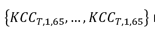
The method may be implemented using MatLAB software, e.g. integrating MEX- C++ routines. Figures 8a and 8b shows an example of the methodology of the invention implemented in automotive door assembly. Figure 8a shows the refined key product characteristics, and Figure 8b shows the key control characteristics. In this case, a design constraint is that the part-to-part gap between mating parts should be between 0.05 and 0.35 mm to ensure a required joining quality. The maximum gap size is directly controlled by properly locating the clamps with respect to laser stitches to compensate for part variation error. It is required to identify the optimum clamp layout {{KCCT,I,I, KCCT,I,6S}) such that the gap for all stitches {{KCCT,I,I, KCCT,UI}) is within the required range of 0.05 to 0.35 mm. In this example, the design task is formulated as follows:


DCi is the maximum gap requirement and DC2 is the minimum gap requirement.
The steps indicated in Figure 1 are then carried out to determine an optimum clamp layout: a physics based model is developed, including calculating clamp orientation directly from the nominal CAD product and parameterising clamp location in order to simulate different clamp layouts; a surrogate model is developed by iteratively re-calling the physics-based model; and feed-forward analysis and feed-back synthesis are performed.
The process results in selection of clamp layout/location and orientation to be used. An assembly process with the defined clamp layout/location and orientation can thus be selected to enable joining/assembly of the component parts in a manner that accommodates the variety of part geometries (i.e. the deviations from the nominal CAD profile for the parts) that could appear within a batch of the parts.
Claims
1 . A system for implementing an assembly process for product manufacture comprising:
a scanner for measuring a geometric profile of a part;
a comparator for calculating variation in the measured profile of the part from a nominal profile of the part and for determining locations of physical constraints on the measured profile caused by a member adjacent to the part during the assembly process;
an evaluator for identifying a set of control parameters that characterise a control scheme, wherein a nominal control scheme for assembly of the nominal profile of the part comprises a set of nominal control parameters, the evaluator arranged to generate a variation response function in respect of the characteristic control parameters and variations in the measured profile, and
an assembly process modifier for modifying the set of control parameter values away from the nominal control parameters based on the variation response function.
2. A system according to claim 1 , wherein the assembly process comprises supporting first and second adjacent parts during a joining process.
3. A system according to claim 1 or 2, wherein the adjacent member comprises a support, fixture or adjacent part in the assembly.
4. A system according to any preceding claim, wherein the evaluator identifies a set of product characteristics comprising locations or dimensions of a plurality of geometric features on the profile of the part, the variation response function linking the characteristic control parameters and product characteristics according to variation in the measured profile.
5. A system according to any preceding claim, wherein the evaluator identifies a set of product characteristics and a plurality of said product characteristics
having a tolerance range associated therewith so as to define design constraints of the product.
6. A system according to any preceding claim, wherein the nominal profile is comprises a geometric definition of the nominal profile and one or more design constraint comprising a location and/or dimension of a joint with an adjacent part on the nominal profile.
7. A system according to any preceding claim, wherein the evaluator identifies a subset of the control characteristics and a corresponding subset of product characteristics using the variation response function in an iterative manner.
8. A system according to any preceding claim, wherein the evaluator performs a feed forward analysis to identify a set of product characteristics from the characteristic control parameters and a feed-back analysis to refine the set of characteristic control parameters based on the identified product characteristics.
9. A system according to any preceding claim wherein the variation response function comprises a part variation mechanistic model and an interaction model between the part and adjacent member.
10. A system according to any preceding claim wherein the e variation response function is a multi-dimensional function.
1 1 . A system according to any preceding claim wherein the comparator comprises a part variation modeller arranged to discretise the nominal and/or measured part profile by defining an element structure for the profile and to determine a deviation from the nominal profile for each element.
12. A system according to any preceding claim wherein the part variation modeller is arranged to parametrize deviations of measured parts from the nominal part profile and thereby identify reoccurring types of deviations according to parameter values thereof.
13. A system according to any preceding claim, wherein the adjacent member comprise a part fixture and the system comprises a part fixture model having libraries for simulating fixture constraints on the freedom of deformation of the part profile relative to one or more fixture location.
14. A system according to any preceding claim, wherein the adjacent member comprise an adjacent part and the system comprises a part-to-part interaction model.
15. A system according to any preceding claim, wherein the assembly process comprises a remote lase welding process.
16. A system according to any preceding claim, wherein the evaluator determines elastic displacement due to part flexibility relative to the physical constraint caused by the adjacent member.
17. A system according to any preceding claim, wherein generation of the variation response function comprising an adaptive sampling technique.
18. A system according to any preceding claim, wherein the evaluator applies a feed forward analysis comprising assigning a set of product characteristics and control characteristics, and evaluating a refined set of product characteristics and control characteristics, wherein the refined set of product characteristics and control characteristics are generated by applying the variation response function to the assigned set of product characteristics and control characteristics.
19. A method of implementing a product assembly process for product manufacture comprising measuring a geometric profile of a part, calculating variation in the measured profile of the part from a nominal profile of the part, determining locations of physical constraints on the measured profile caused by a member adjacent to the part during the assembly process, identifying a set of control parameters that characterise a control scheme, wherein a nominal control
scheme for assembly of the nominal profile of the part comprises a set of nominal control parameters, generating a variation response function based on the calculated variation and locations of physical constraints, and modifying the set of nominal control parameters so as to output a modified set of control parameters based on the variation response function.
20. A data carrier comprising machine readable instructions for operation of one or more processor to modify product assembly control scheme by: reading a geometric profile of a measured part for assembly in the product; calculating variation in the measured geometric profile of the part from a nominal profile of the part; determining locations of physical constraints on the measured profile due to one or more member adjacent to the part during the assembly process; identifying a set of control parameters that characterise a product assembly control scheme, wherein a nominal control scheme for assembly of the nominal profile of the part comprises a set of nominal control parameters; generating a variation response function based on the calculated variation and the locations of physical constraints; and, modifying the set of nominal control parameters so as to output a modified set of control parameters based on the variation response function.
Applications Claiming Priority (2)
| Application Number | Priority Date | Filing Date | Title |
|---|---|---|---|
| GB1615378.5 | 2016-09-09 | ||
| GBGB1615378.5A GB201615378D0 (en) | 2016-09-09 | 2016-09-09 | Product assembly systems |
Publications (1)
| Publication Number | Publication Date |
|---|---|
| WO2018046950A1 true WO2018046950A1 (en) | 2018-03-15 |
Family
ID=57234531
Family Applications (1)
| Application Number | Title | Priority Date | Filing Date |
|---|---|---|---|
| PCT/GB2017/052641 Ceased WO2018046950A1 (en) | 2016-09-09 | 2017-09-08 | Product assembly systems |
Country Status (2)
| Country | Link |
|---|---|
| GB (1) | GB201615378D0 (en) |
| WO (1) | WO2018046950A1 (en) |
Cited By (1)
| Publication number | Priority date | Publication date | Assignee | Title |
|---|---|---|---|---|
| CN119249627A (en) * | 2024-09-12 | 2025-01-03 | 西安工程大学 | A method for analyzing assembly accuracy based on multi-stage linearized contact |
Citations (2)
| Publication number | Priority date | Publication date | Assignee | Title |
|---|---|---|---|---|
| US6167607B1 (en) * | 1981-05-11 | 2001-01-02 | Great Lakes Intellectual Property | Vision target based assembly |
| DE102005044274A1 (en) * | 2005-09-16 | 2007-03-29 | Daimlerchrysler Ag | Automobile bodywork quality control, at the production line, scans the contour for the actual contour to be compared with a three-dimensional nominal contour |
-
2016
- 2016-09-09 GB GBGB1615378.5A patent/GB201615378D0/en not_active Ceased
-
2017
- 2017-09-08 WO PCT/GB2017/052641 patent/WO2018046950A1/en not_active Ceased
Patent Citations (2)
| Publication number | Priority date | Publication date | Assignee | Title |
|---|---|---|---|---|
| US6167607B1 (en) * | 1981-05-11 | 2001-01-02 | Great Lakes Intellectual Property | Vision target based assembly |
| DE102005044274A1 (en) * | 2005-09-16 | 2007-03-29 | Daimlerchrysler Ag | Automobile bodywork quality control, at the production line, scans the contour for the actual contour to be compared with a three-dimensional nominal contour |
Cited By (1)
| Publication number | Priority date | Publication date | Assignee | Title |
|---|---|---|---|---|
| CN119249627A (en) * | 2024-09-12 | 2025-01-03 | 西安工程大学 | A method for analyzing assembly accuracy based on multi-stage linearized contact |
Also Published As
| Publication number | Publication date |
|---|---|
| GB201615378D0 (en) | 2016-10-26 |
Similar Documents
| Publication | Publication Date | Title |
|---|---|---|
| Rausch et al. | Monte Carlo simulation for tolerance analysis in prefabrication and offsite construction | |
| Moroni et al. | Towards early estimation of part accuracy in additive manufacturing | |
| CN102105908B (en) | Method and device for production of master pattern tool | |
| Söderberg et al. | Virtual geometry assurance process and toolbox | |
| Yu et al. | Extended interference matrices for exploded view of assembly planning | |
| EP3082055B1 (en) | Rotorcraft component simulation using scan-based geometry | |
| Schleich et al. | Status and prospects of skin model shapes for geometric variations management | |
| Schleich et al. | A quantitative comparison of tolerance analysis approaches for rigid mechanical assemblies | |
| EP3382582B1 (en) | Method for generating a simulation-model | |
| WO2018046948A1 (en) | Three-dimensional shape error detection | |
| Abellán-Nebot et al. | Manufacturing variation models in multi-station machining systems | |
| Moroni et al. | Geometric inspection planning as a key element in industry 4.0 | |
| D’Emilia et al. | Uncertainty assessment for measurement and simulation in selective laser melting: a case study of an aerospace part | |
| Radvar-Esfahlan et al. | Nonrigid geometric metrology using generalized numerical inspection fixtures | |
| Barnfather et al. | Efficient compensation of dimensional errors in robotic machining using imperfect point cloud part inspection data | |
| Schleich et al. | Skin model shapes: Offering new potentials for modelling product shape variability | |
| Tlija et al. | A novel model for the tolerancing of nonrigid part assemblies in computer aided design | |
| Katona et al. | Integrating optical 3D measurement techniques in pipe bending: a model-based approach minimizing waste by deriving real functional design behaviour | |
| US20220414904A1 (en) | Method of compensating for shrinkage and distortion using scans | |
| WO2018046950A1 (en) | Product assembly systems | |
| Claus et al. | Decomposing deviations of scanned surfaces of sheet metal assemblies | |
| Kaisarlis | A systematic approach for geometrical and dimensional tolerancing in reverse engineering | |
| Aoufi et al. | An advanced framework for tolerance analysis of cam-clamping devices integrating unified Jacobian–Torsor model, Monte Carlo simulation, and bootstrap technique | |
| Babu et al. | Shape error modelling and analysis by conditional simulations of Gaussian random fields for compliant non-ideal sheet metal parts | |
| Das et al. | Parametric effect analysis of free-form shape error during sheet metal forming |
Legal Events
| Date | Code | Title | Description |
|---|---|---|---|
| 121 | Ep: the epo has been informed by wipo that ep was designated in this application |
Ref document number: 17783958 Country of ref document: EP Kind code of ref document: A1 |
|
| NENP | Non-entry into the national phase |
Ref country code: DE |
|
| 122 | Ep: pct application non-entry in european phase |
Ref document number: 17783958 Country of ref document: EP Kind code of ref document: A1 |