WO2018042573A1 - 無線通信システム、基地局装置、端末装置、及び特定情報送受信方法 - Google Patents
無線通信システム、基地局装置、端末装置、及び特定情報送受信方法 Download PDFInfo
- Publication number
- WO2018042573A1 WO2018042573A1 PCT/JP2016/075555 JP2016075555W WO2018042573A1 WO 2018042573 A1 WO2018042573 A1 WO 2018042573A1 JP 2016075555 W JP2016075555 W JP 2016075555W WO 2018042573 A1 WO2018042573 A1 WO 2018042573A1
- Authority
- WO
- WIPO (PCT)
- Prior art keywords
- base station
- information
- processing unit
- control
- communication system
- Prior art date
- Legal status (The legal status is an assumption and is not a legal conclusion. Google has not performed a legal analysis and makes no representation as to the accuracy of the status listed.)
- Ceased
Links
Images








Classifications
-
- H—ELECTRICITY
- H04—ELECTRIC COMMUNICATION TECHNIQUE
- H04W—WIRELESS COMMUNICATION NETWORKS
- H04W88/00—Devices specially adapted for wireless communication networks, e.g. terminals, base stations or access point devices
- H04W88/02—Terminal devices
- H04W88/06—Terminal devices adapted for operation in multiple networks or having at least two operational modes, e.g. multi-mode terminals
Definitions
- the present invention relates to a radio communication system, a base station device, a terminal device, and a specific information transmission / reception method.
- PWS Public Warning System
- LTE Long Term Evolution
- PWS Public Warning System
- a wireless communication system with PWS, for example, warning information and the like can be made widely known to the public.
- ETWS Earthquake TsunamiarnWarning System
- CMAS Common Mobile Alert System
- ETWS is a system that distributes warning information such as earthquakes, tsunamis, and tornadoes to terminal devices.
- CMAS is a system that distributes warning information such as child abduction and disappearance, president message, and the like to a terminal device.
- Examples of technologies related to such a wireless communication system include the following. That is, in HetNet (Heterogeneous Network), when a terminal is communicating with a small base station using a second carrier, the user terminal is configured to receive paging information from a macro base station using the first carrier.
- HetNet Heterogeneous Network
- a terminal when a terminal performs carrier aggregation, it provides a wireless communication system in which the terminal can receive necessary broadcast information while reducing the number of times of reception of a paging message of a terminal other than a specific cell. It can be suppressed.
- one disclosure is to provide a radio communication system, a base station apparatus, a terminal apparatus, and a specific information transmission / reception method that avoid redundant use of radio resources.
- a first radio communication system including a first base station apparatus and a first control apparatus, a second radio communication system including a second base station apparatus and a second control apparatus,
- a wireless communication system including a terminal device capable of communicating with the first and second base station devices
- the first control device notifies the first base station device of specific information.
- the first base station device is located in the first base station device with control information for performing standby control on the second base station device when the first base station device receives the specific information.
- a first transmission unit that transmits to the terminal device, and the second base station device includes a second transmission unit that transmits the specific information received from the second control device to the terminal device;
- the terminal apparatus transmits the control transmitted from the first base station apparatus.
- a receiving unit that receives the specific information transmitted from the second base station device, and a control unit that performs standby control on the second base station device based on the control information .
- a radio communication system it is possible to provide a radio communication system, a base station apparatus, a terminal apparatus, and a specific information transmission / reception method that avoid redundant use of radio resources.
- FIG. 1 is a diagram illustrating a configuration example of a wireless communication system.
- FIG. 2 is a diagram illustrating a configuration example of the MME.
- FIG. 3 is a diagram illustrating a configuration example of a base station.
- FIG. 4 is a diagram illustrating a configuration example of a base station.
- FIG. 5 is a diagram illustrating a configuration example of a terminal.
- FIG. 6 is a diagram illustrating a configuration example of a terminal.
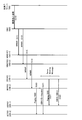
- FIG. 7 is a sequence diagram showing an overall operation example.
- FIG. 8A and FIG. 8B are diagrams illustrating examples of standby designation paging information.
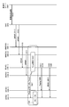
- FIG. 10 is a sequence diagram illustrating an operation example of the entire FIG. 9.
- FIG. 11 is a sequence diagram illustrating an operation example of the entire FIG. 10.
- FIG. 10 is a sequence diagram illustrating an operation example of the entire FIG. 9.
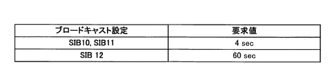
- FIG. 11 is a diagram illustrating an example of request values.
- FIG. 12 is a sequence diagram illustrating an overall operation example.
- FIG. 13 is a diagram illustrating a configuration example of the MME.
- FIG. 14 is a diagram illustrating a configuration example of a base station.
- FIG. 15 is a diagram illustrating an example of a WRWR message.
- FIG. 16 is a diagram illustrating an example of a system change message.
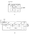
- FIG. 17A illustrates an MME
- FIG. 7B illustrates a hardware configuration example of a base station.
- FIG. 18A illustrates a base station
- FIG. 8B illustrates a hardware configuration example of a terminal.
- FIG. 19 is a diagram illustrating a hardware configuration example of a terminal.
- FIG. 20 is a diagram illustrating a configuration example of a wireless communication system.
- FIG. 1 is a diagram illustrating a configuration example of a wireless communication system 10 according to the first embodiment.
- the wireless communication system 10 includes a base station apparatus (hereinafter may be referred to as “base station”) 100-1, a terminal apparatus (or UE (User Equipment); hereinafter referred to as “terminal”), MME (Mobility Management Entity) 300-1 and S / P-GW 600-1.
- the base station 100-1, the terminal 200-1, the MME 300-1, and the S / P-GW 600-1 are wireless communication systems that can communicate using, for example, a communication method based on LTE or LTE-Advanced. .
- a communication method is called, for example, a fourth-generation mobile communication method (4G: the 4th generation Mobile communication) (hereinafter sometimes referred to as “4G method” or “4G”). Therefore, the base station 100-1, the terminal 200-1, the MME 300-1, and the S / P-GW 600-1 are, for example, a 4G compatible base station, MME, and S / P-GW 600-1.
- the radio communication system 10 includes a base station 100-2, a terminal 200-2, an MME 300-2, and an S / P-GW 600-2.
- the base station 100-2, the terminal 200-2, the MME 300-2, and the S / P-GW 600-2 may be referred to as, for example, a fifth generation mobile communication system (hereinafter referred to as “5G system” or “5G”).
- 5G system a fifth generation mobile communication system
- 5G system fifth generation mobile communication system
- the base station 100-2, the terminal 200-2, the MME 300-2, and the S / P-GW 600-2 are a 5G-compatible base station, terminal, MME, and S / P-GW 600-2.
- the terminal 200-2 is compatible with both the 4G scheme and the 5G scheme, and is capable of wireless communication with the two base stations 100-1 and 100-2.
- the wireless communication system 10 further includes a CBC (Cell Broadband Center) 400 and a Japan Meteorological Agency server 500.
- CBC 400 and the Japan Meteorological Agency server 500 correspond to CBC and CBE (Cell Broadcast Entity) in the PWS system, respectively.
- Base station 100-1 performs 4G wireless communication with terminals 200-1 and 200-2 located within the service provision range of the local station, and provides various services to terminals 200-1 and 200-2. It is possible to provide. In the first embodiment, an example of an emergency information distribution service will be described as an example of a provided service. Further, the base station 100-1 can transmit / receive control information and the like to / from the MME 300-1, and can transmit / receive user data (or individual data) to / from the S / P-GW 600-1. .
- the base station 100-2 can provide various services to the terminal 200-2 by performing 5G wireless communication with the terminal 200-2 located within the service provision range of the own station. As in the case of the base station 100-1, an emergency information distribution service will be described below as an example of a provided service.
- the base station 100-2 can transmit / receive control information to / from the MME 300-2 and transmit / receive user data to / from the S / P-GW 600-2.
- the terminals 200-1 and 200-1 are wireless communication devices such as feature phones, smartphones, personal computers, tablet terminals, and game devices, for example. As described above, terminal 200-1 can perform wireless communication with base station 100-1 using a 4G scheme (for example, LTE scheme). The terminal 200-2 can perform 4G wireless communication with the base station 100-1 and 5G wireless communication with the base station 100-2.
- 4G scheme for example, LTE scheme
- 5G wireless communication with the base station 100-2.
- the MMEs 300-1 and 300-2 are control devices that respectively control the base stations 100-1 and 100-2, for example. Further, MME 300-1 and 300-2 receive the emergency information transmitted from CBC 400, and transmit the received emergency information to base stations 100-1 and 100-2, respectively.
- the MME 300-1 can perform control defined by the 4G scheme on the base station 100-1 and the S / P-GW 600-1.
- the MME 300-1 can perform handover control of the terminal 200-1 and set a bearer from the S / P-GW 600-1 to the base station 100-1.
- the MME 300-2 can control the base station 100-2 and the S / P-GW 600-2, for example, by the 5G method.
- the MME 300-2 can perform the same processing as the MME 300-1 on the base station 100-2 and the S / P-GW 600-2.
- the CBC 400 receives, for example, emergency information transmitted from the Japan Meteorological Agency server 500, and transmits the received emergency information to the MMEs 300-1 and 300-2.
- the CBC 400 can specify an area where emergency information is to be transmitted based on the received emergency information, and can transmit the emergency information to the MMEs 300-1 and 300-2 arranged in the specified area. It is.
- the CBC 400 may be one of nodes connected to a mobile network (or core network), for example.
- the Meteorological Agency server 500 is a server device that transmits emergency information to the CBC 400, for example. For example, in the case of an earthquake, when a sensor embedded in the ground detects shaking, the information is notified to the Japan Meteorological Agency server 500. Then, the meteorological agency server 500 generates warning information about the earthquake and transmits it to the CBC 400 when the detected shaking is equal to or greater than a certain level.
- S / P-GWs 600-1 and 600-2 include, for example, S-GW (ServingServGateway) and P-GW (PDN (Packet (Data Network) Gateway).
- the S / P-GWs 600-1 and 600-2 transmit user data obtained from the Internet or the like to the base stations 100-1 and 100-2, and receive from the base stations 100-1 and 100-2, respectively. Sent user data to the Internet.
- the S / P-GW 600-1 performs processing specified as the 4G system
- the S / P-GW 600-2 performs processing specified as the 5G system.
- FIG. 2 shows a configuration example of the MME 300-1.
- the MME 300-1 includes an IP (Internet Protocol) processing unit 310-1, a WRWR (Write Replace Warning Request) processing unit 320-1, and a signaling processing unit 330-1.
- IP Internet Protocol
- WRWR Write Replace Warning Request
- the IP processing unit 310-1 transmits / receives packet data using the IP protocol to / from the CBC 400 and the base stations 100-1 and 100-2, for example. For example, upon receiving packet data including a message regarding emergency information from CBC 400, IP processing unit 310-1 extracts a message included in the packet data, and outputs the extracted message to WRWR processing unit 320-1.
- the WRWR message is a message requesting transmission of emergency information in a mobile network, for example.
- FIG. 15 shows an example of information elements included in the WRWR message.
- the WRWR message includes, for example, information type (earthquake, tsunami, missile launch, etc.), retransmission cycle, number of retransmissions, message content (content), and the like.
- the WRWR message is generated according to the emergency information, for example, in the CBC 400 that has received the emergency information, and transmitted to the MME 300-1.
- the IP processing unit 310-1 receives and receives, for example, a WRWR message and a distribution instruction to all base stations 100-1 connected to the MME 300-1 from the signaling processing unit 330-1. Packet data including the received message is generated and transmitted to the base station 100-1.
- the WRWR processing unit 320-1 receives a WRWR message from the IP processing unit 310-1, and outputs the received WRWR message to the signaling processing unit 330-1.
- the signaling processing unit 330-1 determines to distribute to all the base stations 100-1 connected to the MME 300-1. Then, the signaling processing unit 330-1 outputs the received WRWR message to the IP processing unit 310-1, and further distributes the WRWR message to all the base stations 100-1 connected to the MME 300-1. Direct to 310-1.
- the signaling processing unit 330-1 may be a notification unit that notifies the base station 100-1 of emergency information, for example.
- FIG. 2 also shows a configuration example of the MME 300-2.
- the MME 300-2 includes an IP processing unit 310-2, a WRWR processing unit 320-2, and a signaling processing unit 330-2.
- the IP processing unit 310-2, the WRWR processing unit 320-2, and the signaling processing unit 330-2 are also the same processes as the IP processing unit 310-1, the WRWR processing unit 320-1, and the signaling processing unit 330-1 in the MME 300-1. I do.
- the signaling processing unit 330-2 determines to distribute the WRWR message to all the base stations 100-2 connected to the MME 300-2. Then, the signaling processing unit 330-2 instructs the IP processing unit 310-2 to distribute the WRWR message to all the base stations 100-2, and the IP processing unit 310-2 receives the signal from the signaling processing unit 330-2. The received WRWR message is transmitted to all base stations 100-2.
- the signaling processing unit 330-2 may also be a notification unit that notifies the base station 100-2 of emergency information, for example.
- IP processing units 310-1 and 310-2 and the signaling processing units 330-1 and 330-2 can process, for example, messages other than the WRWR message.
- An example of such a message is a message regarding handover.
- the MMEs 300-1 and 300-2 exchange such messages with the base stations 100-1 and 100-2, respectively.
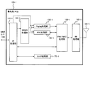
- FIG. 3 is a diagram illustrating a configuration example of the base station 100-1.
- the base station 100-1 is a 4G compatible base station.
- the base station 100-1 includes an IP processing unit 110-1, a WRWR processing unit 120-1, a paging processing unit (paging processing unit) 130-1, and an RRC (Radio Resource Control) processing unit 140-1. Further, the base station 100-1 includes a PHY / MAC (Physical layer and MAC (Media Access Control) layer) processing unit 150-1, an RF (Radio Frequency) processing unit 160-1, and an S1AP (S1 Application Protocol) processing unit 170. -1 and antenna 101-1.
- PHY / MAC Physical layer and MAC (Media Access Control) layer) processing unit 150-1
- RF Radio Frequency
- S1AP S1 Application Protocol
- the IP processing unit 110-1 exchanges packet data with the MME 300-1 and the S / P-GW 600-1. For example, the IP processing unit 110-1 extracts a WRWR message from the packet data received from the MME 300-1, and outputs the extracted WRWR message to the WRWR processing unit 120-1. For example, the IP processing unit 110-1 extracts a message other than the WRWR message received from the MME 300-1, and outputs the extracted message to the paging processing unit 130-1 and the RRC processing unit 140-1. Further, for example, the IP processing unit 110-1 extracts user data from packet data received from the S / P-GW 600-1, and outputs the extracted user data to the PHY / MAC processing unit 150-1.
- the IP processing unit 110-1 determines what kind of message is included in the packet data based on the header information included in the packet data. Then, the IP processing unit 110-1 converts the extracted message or the like into the WRWR processing unit 120-1, the Paging processing unit 130-1 and the RRC processing unit 140-1, or the PHY / MAC processing unit 150 according to the determination result. Output to -1.
- the IP processing unit 110-1 receives user data from the PHY / MAC processing unit 150-1, generates packet data including the received user data, and transmits the packet data to the S / P-GW 600-1.
- the IP processing unit 110-1 exchanges packet data with the MME 300-1 and the S / P-GW 600-1, for example, via the S1AP processing unit 170-1.
- S1AP packet data can be exchanged with the MME 300-1 and the S / P-GW 600-1.
- the IP processing unit 110-1 may be, for example, a receiving unit that receives emergency information transmitted from the MME 300-1.
- the WRWR processing unit 120-1 When the WRWR processing unit 120-1 receives the WRWR message from the IP processing unit 110-1, the WRWR processing unit 120-1 outputs the received WRWR message to the paging processing unit 130-1 and the RRC processing unit 140-1.
- the paging processing unit 130-1 when receiving a WRWR message from the WRWR processing unit 120-1, the paging processing unit 130-1 generates paging information (or paging message) for notifying update of SIB (System Information Block) information, and generates the generated paging information. Is notified to the PHY / MAC processing unit 150-1.
- SIB System Information Block
- the base station 100-1 transmits Paging information indicating update of SIB information to the terminals 200-1 and 200-2, so that the terminals 200-1 and 200-2 include SIBs including warning information such as SIB10 and SIB11. Can be received.
- the base station 100-1 broadcasts warning information using, for example, SIB10 or SIB11.
- the RRC processing unit 140-1 When the RRC processing unit 140-1 receives the WRWR message from the WRWR processing unit 120-1, the RRC processing unit 140-1 converts the WRWR message into SIB10 and SIB11. For example, the RRC processing unit 140-1 generates SIB10 and SIB11 by distributing information included in the WRWR message to SIB10 and SIB11. The RRC processing unit 140-1 outputs SIB10 and SIB11 to the PHY / MAC processing unit 150-1.
- the RRC processing unit 140-1 may be, for example, a transmission unit that transmits emergency information to the terminal 200-1 located in the area.
- the base station 100-1 broadcasts warning information using SI (System Information).
- SI System Information
- 25 or more types of SIBs are defined.
- SIB10 and SIB11 are used.
- the base station 100-1 uses the SIB 10 to notify the disaster type and the like, and then uses the SIB 11 to notify a warning message related to the disaster.
- the RRC processing unit 140-1 performs scheduling such as allocating radio resources to the terminal 200-1, for example, generates control information including a scheduling result, and outputs the control information to the PHY / MAC processing unit 150-1. .
- the control information is transmitted to terminal 200-1.
- the terminal 200-1 can perform wireless communication with the base station 100-1 using the assigned wireless resource, and can transmit and receive user data (or individual data) and the like.
- the RRC processing unit 140-1 receives control information from the PHY / MAC processing unit 150-1, performs processing on the control information, and terminates the control information.
- the PHY / MAC processing unit 150-1 uses, for example, a physical layer signal (control signal) for the paging information output from the paging processing unit 130-1 and the broadcast information and control information output from the RRC processing unit 140-1. Or bit information).
- the PHY / MAC processing unit 150-1 outputs the converted signal to the RF processing unit 160-1.
- the PHY / MAC processing unit 150-1 extracts control information, user data, and the like from the baseband signal output from the RF processing unit 160-1. For example, control information, user data, and the like are transmitted by terminal 200-1 using a predetermined channel. Therefore, when the RF processing unit 160-1 receives a radio signal, information indicating which channel is received is output to the PHY / MAC processing unit 150-1, and the PHY / MAC processing unit 150-1 Control information and user data may be extracted based on the information. The PHY / MAC processing unit 150-1 outputs the extracted control information to the RRC processing unit 140-1, and outputs the extracted user data and the like to the IP processing unit 110-1.
- the RF processing unit 160-1 When the RF processing unit 160-1 receives a signal from the PHY / MAC processing unit 150-1, the RF processing unit 160-1 performs frequency conversion processing on the signal and converts the signal into a radio signal in a radio band.
- the RF processing unit 160-1 may perform frequency conversion from a baseband band to a frequency band that can be used as a 4G system, and may be referred to as a wireless signal (hereinafter referred to as a “4G-compatible wireless signal”).
- the RF processing unit 160-1 outputs a 4G compatible radio signal to the antenna 101-1.
- the RF processing unit 160-1 performs frequency conversion processing on the 4G-compatible radio signal output from the antenna 101-1, and converts it to a baseband signal.
- the RF processing unit 160-1 outputs the converted signal to the PHY / MAC processing unit 150-1. Also in this case, for example, the RF processing unit 160-1 obtains the signal by performing frequency conversion from a frequency band that can be used as a 4G system to a baseband band.
- the antenna 101-1 transmits the 4G-compatible radio signal received from the RF processing unit 160-1 to the terminals 200-1 and 200-2. Further, antenna 101-1 receives the 4G-compatible radio signal transmitted from terminals 200-1 and 200-2, and outputs the received 4G-compatible radio signal to RF processing section 160-1.
- the S1AP processing unit 170-1 receives, for example, user data from the IP processing unit 110-1, converts it into a SIAP packet, and outputs it to the IP processing unit 110-1. Accordingly, for example, the IP processing unit 110-1 can transmit an IP packet including the S1AP packet in the payload area to the MME 300-1 or the S / P-GW 600-1.
- the S1AP processing unit 170-1 receives, for example, an IP packet from the IP processing unit 110-1, extracts a message or user data included in the S1AP packet from the IP packet, and transmits the extracted message or user data to the IP packet.
- the data is output to the processing unit 110-1.
- the IP processing unit 110-1 can extract a message, user data, and the like from a packet transmitted from the MME 300-1 or the S / P-GW 600-1.
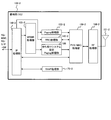
- FIG. 4 is a diagram illustrating a configuration example of the base station 100-2.
- the base station 100-2 is a 5G compatible base station.
- the base station 100-2 includes an IP processing unit 110-2, a WRWR processing unit 120-2, a paging processing unit 130-2, and an RRC processing unit 140-2.
- the base station 100-2 includes a PHY / MAC processing unit 150-2, an RF processing unit 160-2, an S1AP processing unit 170-2, and an antenna 101-2.
- the base station 100-2 includes a standby system designation paging processor (hereinafter also referred to as “standby paging processor”) 180.
- IP processor 110-2, WRWR processor 120-2, Paging processor 130-2, RRC processor 140-2, PHY / MAC processor 150-2, RF processor 160-2, S1AP processor 170- 2 and the antenna 101-2 are, for example, substantially the same as each block of the base station 100-1.
- the IP processing unit 110-2 may be a receiving unit that receives emergency information from the MME 300-2, for example, like the IP processing unit 110-1 of the base station 100-1.
- the IP processing unit 110-2 exchanges packet data between the 5G compatible MME 300-2 and the S / P-GW 600-2.
- the WRWR processing unit 120-2 When the WRWR processing unit 120-2 receives the WRWR message from the IP processing unit 110-2, the WRWR processing unit 120-2 does not output the WRWR message to the paging processing unit 130-2 and the RRC processing unit 140-2, but waits for the paging processing unit 180. Output to. For this reason, the base station 100-2 does not notify emergency information to the terminal 200-2 in the area using the SIB10, SIB11, or the like.
- the signal output from the PHY / MAC processing unit 150-2 is a radio signal in a frequency band that can be used in 5G (hereinafter sometimes referred to as a “5G-compatible radio signal”). And output to the antenna 101-2. Further, the RF processing unit 160-2 performs a frequency conversion process from the frequency band usable as 5G to the baseband band on the radio signal output from the antenna 101-2, thereby converting the baseband band signal. Extract.
- the antenna 101-2 transmits a 5G compatible radio signal to the terminal 200-2, and receives the 5G compatible radio signal transmitted from the terminal 200-2.
- the standby paging processing unit 180 when the standby paging processing unit 180 receives a WRWR message from the WRWR processing unit 120-2, the standby paging processing unit 180 causes the terminal 200-2 located in the base station 100-2 to perform standby control in the 4G scheme (or instructions) Paging information (or control information) is generated.
- This paging information may be referred to as standby designation paging information, for example.
- the standby paging processor 180 may be, for example, a transmitter that transmits control information to the terminal 200-2.
- FIG. 8A shows an example of standby designation paging information.
- the waiting designation paging information includes “Waiting System Change ⁇ 3G, 4G, reserve ⁇ ”.
- the terminal 200-2 that has received the standby designation paging information confirms “Waiting System Change ⁇ 3G, 4G, reserve ⁇ ” to perform standby processing so as to perform standby in the 4G system instead of 5G.
- “ ⁇ 3G, 4G ⁇ ” represents, for example, a standby destination (or a standby change destination), indicates that standby is performed from the 5G system to the 4G system, and when the 4G system cannot be used, It also represents performing standby by 3G system. If the terminal 200-2 cannot use the 4G method, the terminal 200-2 waits using the 3G method.
- the standby designation paging information for example, switches the standby from the base station 100-2 to the 4G base station 100-1 for the terminal 200-2 waiting for the 5G base station 100-2. It may be control information instructing this.
- the standby paging processing unit 180 outputs the generated standby specification paging information to the PHY / MAC processing unit 150-2.
- the standby designation paging information is transmitted to the terminal 200-2.
- FIG. 5 illustrates a configuration example of the terminal 200-1.
- the terminal 200-1 is, for example, a 4G compatible terminal.
- the terminal 200-1 includes an antenna 201-1, an RF processing unit 210-1, a PHY / MAC processing unit 220-1, a paging processing unit 230-1, an RRC processing unit 240-1, an IP processing unit 250-1, and WRWR information.
- a processing unit 260-1 and an application processing unit 270-1 are provided.
- the antenna 201-1 receives the radio signal (4G compatible radio signal) transmitted from the base station 100-1, and outputs the received radio signal to the RF processing unit 210-1. Further, the antenna 201-1 transmits the radio signal (4G compatible radio signal) output from the RF processing unit 210-1 to the base station 100-1.
- the RF processing unit 210-1 performs frequency conversion processing on the radio signal output from the antenna 201-1, and converts it to a baseband signal. For example, the RF processing unit 210-1 obtains a baseband signal by converting a radio signal from a frequency band usable in 4G to a baseband band. The RF processing unit 210-1 outputs the converted signal to the PHY / MAC processing unit 220-1.
- the RF processing unit 210-1 performs frequency conversion processing on the signal output from the PHY / MAC processing unit 220-1, and converts the signal into a wireless signal in a wireless band. For example, the RF processing unit 210-1 obtains a 4G-compatible radio signal by converting a baseband signal into a radio signal in a frequency band usable in 4G. The RF processing unit 210-1 outputs the converted radio signal to the antenna 201-1.
- the PHY / MAC processing unit 220-1 extracts Paging information, broadcast information, control information, user data, and the like from the signal output from the RF processing unit 210-1.
- the paging information is transmitted from the base station 100-1 using the paging channel
- the broadcast information is transmitted using the broadcast channel
- the control information is transmitted using the control channel
- the user data is transmitted using the shared channel.
- the RF processing unit 210-1 outputs information indicating which channel (or frequency) is used to receive the radio signal to the PHY / MAC processing unit 220-1.
- the PHY / MAC processing unit 220-1 extracts paging information, broadcast information, control information, user data, or the like based on the information.
- the PHY / MAC processing unit 220-1 outputs the paging information to the paging processing unit 230-1, the broadcast information and control information to the RRC processing unit 240-1, and the user data to the IP processing unit 250-1.
- the PHY / MAC processing unit 220-1 receives control information from the RRC processing unit 240-1, for example, receives user data (or IP packet) from the IP processing unit 250-1, and receives control information and user data. Convert to physical layer signal (or bit information). The PHY / MAC processing unit 220-1 outputs the converted signal to the RF processing unit 210-1.
- the paging processing unit 230-1 receives the paging information output from the PHY / MAC processing unit 220-1, performs a process on the received paging information, and terminates the paging information.
- the RRC processing unit 240-1 receives the broadcast information and control information output from the PHY / MAC processing unit 220-1. In this case, for example, when the RRC processing unit 240-1 receives the SIB10 and SIB11, the RRC processing unit 240-1 outputs the information (or WRWR message) included in the SIB10 and SIB11 to the WRWR information processing unit 260-1.
- the RRC processing unit 240-1 when receiving the control information and other notification information, performs a process corresponding to the information and terminates the control information and the other notification information.
- processing for control information include the following processing. That is, RRC processing section 240-1 extracts from the control information the scheduling result assigned by base station 100-1 to terminal 200-1. Then, the RRC processing unit 240-1 receives or extracts the user data addressed to the terminal 200-1 based on the extracted scheduling result, and the PHY / MAC processing unit 220-1 and the RF processing unit 210-1 To instruct.
- the IP processing unit 250-1 receives user data from the PHY / MAC processing unit 220-1, and performs IP processing from the received user data. For example, the PHY / MAC processing unit 220-1 extracts user data as an IP packet and outputs the extracted IP packet to the IP processing unit 250-1. Examples of IP processing include processing such as extracting user data from an IP packet. The IP processing unit 250-1 outputs the extracted user data to the application processing unit 270-1.
- the IP processing unit 250-1 receives user data from the application processing unit 270-1, generates an IP packet including the received user data, and outputs the IP packet to the PHY / MAC processing unit 220-1.
- the PHY / MAC processing unit 220-1 for example, an IP packet is converted into a baseband signal.
- the WRWR information processing unit 260-1 extracts, for example, warning information from the WRWR information (or WRWR message) output from the RRC processing unit 240-1, and outputs the warning information to the application processing unit 270-1.
- a warning sound is generated for warning information output from the WRWR information processing unit 260-1, or a warning message is popped up on the screen of the terminal 200-1.
- the application processing unit 270-1 can execute various applications in addition to the application for the warning information, for example.
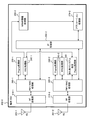
- FIG. 6 shows a configuration example of the terminal 200-2.
- the terminal 200-2 is a 5G compatible terminal, but is also a terminal compatible with 4G.
- the terminal 200-2 includes an antenna 201-1, an RF processing unit 210-1, a PHY / MAC processing unit 220-1, a paging processing unit 230-1, an RRC processing unit 240-1, an IP processing unit 250-2, and WRWR information.
- a processing unit 260-2 and an application processing unit 270-2 are provided.
- the processes in the RF processing unit 210-1, the PHY / MAC processing unit 220-1, the paging processing unit 230-1, and the RRC processing unit 240-1 are the same as, for example, each unit of the terminal 200-1.
- the antenna 201-1 exchanges radio signals (4G compatible radio signals) with the base station 100-1.
- the terminal 200-2 includes an antenna 201-2, an RF processing unit 210-2, a PHY / MAC processing unit 220-2, a paging processing unit 230-2, an RRC processing unit 240-2, a standby designation paging processing unit (hereinafter referred to as a “paging processing unit”). , Sometimes referred to as a “standby paging processor”) 280.
- the antenna 201-2, the RF processing unit 210-2, the PHY / MAC processing unit 220-2, the paging processing unit 230-2, and the RRC processing unit 240-2 correspond to, for example, the 5G system.
- the antenna 201-2 exchanges radio signals (5G compatible radio signals) with the base station 100-2.
- the RF processing unit 210-2 performs, for example, frequency conversion processing on the radio signal output from the antenna 201-2, and converts a frequency band signal used in the 5G method into a baseband signal.
- the RF processing unit 210-2 outputs the converted signal to the PHY / MAC processing unit 220-2.
- the RF processing unit 210-2 performs, for example, frequency conversion processing on the signal output from the PHY / MAC processing unit 220-2, and the baseband signal can be used in the 5G system. Conversion to a radio signal (5G compatible radio signal). The RF processing unit 210-2 outputs the converted radio signal to the antenna 201-2.
- the two RF processing units 210-1 and 210-2 for example, control information (for example, standby designation paging information) transmitted from the base station 100-2 and emergency information transmitted from the base station 100-1. It may be a receiving unit that receives.
- the PHY / MAC processing unit 220-2 extracts standby designation paging information, control information, user data, and the like from the baseband signal output from the RF processing unit 210-2. Then, the PHY / MAC processing unit 220-2 receives the standby designation paging information as the standby paging processing unit 280, the other paging information as the paging processing unit 230-2, the control information as the RRC processing unit 240-2, and the user data as the IP. Each is output to the processing unit 250-2. For example, the PHY / MAC processing unit 220-2 obtains paging information, control information, user data, and the like based on information on the reception channel received from the RF processing unit 210-2 and type information included in the MAC layer packet. It is possible to identify and output.
- the PHY / MAC processing unit 220-2 performs physical layer processing on the control information output from the RRC processing unit 240-2 and the user data (or IP packet) output from the IP processing unit 250-2. Convert to signal (or bit information). The PHY / MAC processing unit 220-2 outputs the converted signal to the RF processing unit 210-2.
- the paging processing unit 230-2 When the paging processing unit 230-2 receives the paging information from the PHY / MAC processing unit 220-2, the paging processing unit 230-2 performs processing for the paging and terminates the paging information.
- the paging information in this case is, for example, paging information other than the standby designation paging information.
- the RRC processing unit 240-2 receives control information from the PHY / MAC processing unit 220-2, for example, and performs processing on the control information. For example, the RRC processing unit 240-2 performs processing such as instructing the PHY / MAC processing unit 220-2 to extract user data addressed to the terminal 200-2 based on the scheduling result included in the control information. .
- the RRC processing unit 240-2 generates, for example, control information and outputs it to the PHY / MAC processing unit 220-2.
- the standby paging processing unit 280 when the standby paging processing unit 280 receives the standby designation paging information from the PHY / MAC processing unit 220-2, the standby paging processing unit 280 sends the standby paging processing unit 280 to the RRC processing units 240-1 and 240-2 according to the communication state of the terminal 200-2. A signal indicating a change in standby is notified.
- the standby paging processor 280 may be, for example, a controller that performs standby control on the base station 100-1.
- the standby paging processing unit 280 performs the following processing.
- the standby paging processor 280 receives the standby specification paging information, and instructs the 4G-compatible RRC processor 240-1 to perform standby. Output a signal.
- the standby paging processor 280 outputs a signal instructing the 5G-compatible RRC processor 240-2 to stop standby.
- the standby paging processing unit 280 notifies the RRC processing unit 240-1 of a signal including information such as SIB change and ETWS instruction included in the standby specification paging information. Based on such a signal, the RRC processing unit 240-1 notifies the RF processing unit 210-1 and the PHY / MAC processing unit 220-1 of the timing at which SIB10 and SIB11 can be received, the reception frequency, and the like. As a result, the RF processing unit 210-1 and the PHY / MAC processing unit 220-1 can receive the SIB10 and SIB11 from the radio signal transmitted from the base station 100-1 and output them to the RRC processing unit 240-1. It becomes possible. Then, the RRC processing unit 240-1 can receive the SIB 10 and the SIB 11 while waiting for the base station 100-1.
- the standby paging processor 280 may newly add a standby on the 4G side while maintaining the communication on the 5G side. Also in this case, when the standby paging processing unit 280 receives the standby designation paging information, the standby paging processing unit 280 outputs a signal including information included in the standby designation paging information to the RRC processing unit 240-1, for example. Is instructed to wait. In this case, the standby paging processing unit 280 maintains the state without outputting any signal to the RRC processing unit 240-2.
- the standby designation paging information may be, for example, control information that instructs the terminal 200-2 communicating with the base station 100-2 to add standby to the base station 100-1.
- the standby designation paging information may be instructed to change or add the standby.
- the standby paging processing unit 180 of the base station 100-2 generates standby designation paging information including information indicating change or addition, and transmits it to the terminal 200-2.
- the standby paging processing unit 280 of the terminal 200-2 instructs the RRC processing unit 240-2 to stop and the RRC processing unit 240-1 to perform standby based on the information.
- the standby paging processor 280 instructs the RRC processor 240-1 to wait based on the information, for example, without instructing the RRC processor 240-2.
- the IP processing unit 250-2 For the user data output from the application processing unit 270-2, the IP processing unit 250-2 generates an IP packet including the user data and the PHY / MAC processing unit 220-1 or PHY / The data is output to the MAC processing unit 220-2. Also, the IP processing unit 250-2 extracts, for example, user data from the IP packets output from the PHY / MAC processing units 220-1 and 220-2, and the extracted user data is extracted from the application processing unit. Output to 270-2.
- the WRWR information processing unit 260-2 extracts warning information from the WRWR information output from the RRC processing unit 240-1, and outputs the warning information to the application processing unit 270-2.
- the application processing unit 270-2 generates a warning sound for the warning information output from the WRWR information processing unit 260-2, or displays a warning message on the screen of the terminal 200-2. To do. Further, the application processing unit 270-2 can execute various applications other than the application for the warning information, for example.
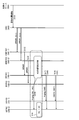
- FIG. 7 shows a sequence example in the wireless communication system 10.
- FIG. 7 is an example in the case of notifying emergency earthquake information, for example.
- the Meteorological Agency server 500 detects an earthquake, the Meteorological Agency server 500 generates an earthquake early warning and transmits it to the CBC 400 (S10).
- the Japan Meteorological Agency server 500 includes, in the earthquake early warning, the area information indicating the area where the earthquake early warning is notified.
- the CBC 400 When the CBC 400 receives the earthquake early warning, the CBC 400 generates a WRWR message and transmits the generated WRWR message to the 4G compatible MME 300-1 and the 5G compatible MME 300-2 (S11, S12). For example, the CBC 400 transmits a WRWR message to the MMEs 300-1 and 300-2 arranged in the area based on the area information included in the earthquake early warning.
- the MME 300-1 When the MME 300-1 receives the WRWR message, the MME 300-1 transmits the received WRWR message to all the subordinate base stations 100-1 (S13).
- the MME 300-2 transmits the received WRWR message to all the subordinate base stations 100-2 (S14).
- the 5G-compatible base station 100-2 when receiving the WRWR message, the 5G-compatible base station 100-2 generates standby designation paging information and transmits the generated standby designation paging information to the terminal 200-2 located in the area (S15).
- the standby paging processing unit 180 receives a WRWR message from the WRWR processing unit 120-2, it generates standby specification paging information, and the generated standby specification paging information is transmitted via the PHY / MAC processing unit 150-2 or the like. To terminal 200-2.
- FIG. 8A shows an example of standby designation paging information.
- the standby paging designation information includes “Waiting System Change ⁇ 3G, 4G, reserve ⁇ ”.
- Other information elements included in the standby paging designation information include, for example, information elements that represent SIB changes.
- “sysminfoInfoModification” is an information element indicating a change in SIB
- “etws-Indication” is an information element indicating ETWS.
- the terminals 200-1 and 200-2 that have received the Paging information including such information elements adjust the reception timing and reception frequency so that the SIB10 and the SIB11 (or emergency information) can be received. And waiting for reception of SIB11.
- the standby paging designation information may be “Waiting System Change ⁇ 3G, 4G, reserve ⁇ ”.
- the base station 100-2 may transmit the paging information indicating the SIB change including the standby paging designation information.
- the terminal 200-2 when receiving the standby designation paging information from the base station 100-2, the terminal 200-2 changes the standby from the 5G compatible base station 100-2 to the 4G compatible base station 100-2 (S16). ).
- the standby paging processor 280 instructs the RRC processor 240-1 to perform standby.
- the standby paging processor 280 may change the standby from 5G to 4G, for example, or may add a 4G standby to the 5G standby.
- the 4G-compatible base station 100-1 when the 4G-compatible base station 100-1 receives the WRWR message, it generates Paging information including SIB changes and transmits them to the terminals 200-1 and 200-2 in the area (S17, 18).
- the paging processing unit 130-1 generates paging information including SIB change, and transmits the generated paging information to the terminals 200-1 and 200-2 via the PHY / MAC processing unit 150-1.
- the 4G-compatible base station 100-1 notifies the terminals 200-1 and 200-2 in which the SIB 10 and SIB 11 are located (S19, S20).
- the RRC processing unit 140-1 generates SIB10 and SIB11, and notifies the terminals 200-1 and 200-2 via the PHY / MAC processing unit 150-1 and the like.
- the terminal 200-2 receives the standby designation paging information (S15), and waits for the 4G compatible base station 100-1 (S16).
- the terminal 200-2 receives the SIB 10 broadcast from the base station 100-1 and SIB11 can be received (S19, S20).
- FIG. 9 shows a sequence example in the wireless communication system 10.
- the 5G-compatible base station 100-2 does not transmit the standby designation paging information even if it receives the WRWR message from the MME 300-1, but similar to the 4G-compatible base station 100-1, Paging information including SIB changes is transmitted to the terminal 200-2 (S30, S32). Then, the base station 100-2 broadcasts emergency information using SIB, similarly to the base station 100-1 (S31, S33).
- the two base stations 100-1 and 100-2 notify the same message regarding the emergency earthquake warning (S31, S33).
- the base station 100-1 transmits a message related to the earthquake early warning (S19, S20), and the base station 100-2 does not transmit such a message. Therefore, in the wireless communication system 10 shown in FIG. 7, compared with the example of FIG. 9, wireless resources are not used redundantly. Therefore, in this wireless communication system 10, it is possible to avoid redundant use of wireless resources.
- the 5G system is currently under consideration in 3GPP, it is expected that the service providing area (or communicable area) will be narrower compared to the 4G system. In that case, it is expected that the 5G terminal 200-2 has a lower probability of receiving emergency information and the like than the 4G terminal 200-1. Therefore, as shown in the wireless communication system 10, even in the case of the 5G terminal 200-2, the emergency information transmitted from the 4G compatible base station 100-1 is received using the 4G system service providing area. By doing so, it becomes possible to increase the possibility of receiving emergency information.
- the second embodiment is an example in which a timer is designated in the standby designation paging information.
- the terminal 200-2 After starting the standby for the 4G-compatible base station 100-2, the terminal 200-2 returns the standby state to the 5G-compatible base station 100-24G when the time specified by the timer has elapsed.
- FIG. 10 shows a sequence example in the second embodiment.
- the base station 100-2 When receiving the WRWR message from the MME 300-2 (S14), the base station 100-2 generates standby designation paging information including a timer and transmits it to the terminal 200-2 (S41).
- the timer may be a time according to a request value requested by ETWS or CMAS, for example.
- FIG. 11 shows an example of request values.
- the time until the SIB10 and SIB11 are transmitted to the terminal 200-2 is required to be within 4 seconds. Yes.
- the time from when the base station 100-2 receives a message from the MME 300-2 to when the SIB 12 is transmitted to the terminal 200-2 is required to be within 60 seconds.
- the standby paging processor 180 sets, for example, a timer value corresponding to the time taken for the base station 100-2 to transmit the SIB10 and SIB11 after receiving the WRWR message from the MME 300-2.
- the standby paging processing unit 180 performs the following processing. That is, standby paging processor 180 receives information included in the WRWR message from WRWR processor 120-2, and sets a timer value based on the information. For example, the standby paging processor 180 sets the timer value to 4 sec for a message related to ETWS and sets the timer value to 60 sec for a message related to CAMS, based on the message content included in the information. The standby paging processing unit 180 generates standby specification paging information including the set timer value and transmits it to the terminal 200-2.
- FIG. 8B shows an example of standby designation paging information including a timer value.
- the standby designation paging information further includes “Timer ⁇ 1, 4,..., 60 ⁇ ” as an information element.
- “Timer ⁇ 1, 4,..., 60 ⁇ ” represents, for example, a timer value. In this example, 1 sec, 4 sec,..., 60 sec can be selected as the timer value. That is, when the terminal 200-2 receives the standby designation paging information including the timer value, the terminal 200-2 refers to other information elements included in the information, selects the timer value, and when the selected timer time has elapsed, the original state It comes to return to.
- the terminal 200-2 performs the following processing.
- the standby paging processing unit 280 selects the timer value based on the information element included in the information. For example, the standby paging processing unit 280 selects 4 sec when an information element indicating ETWS is included, and selects 60 sec when an information element indicating CMAS is included. Then, the standby paging processor 280 starts counting the timer time from the time when the RRC processor 240-1 is instructed to wait (or the time when the standby designation paging information including the timer value is received).
- the RRC processing unit 240-1 When the time elapses, the RRC processing unit 240-1 is instructed to end the 4G standby. As a result, the terminal 200-2 can return to the standby state before receiving the standby designation paging information including the timer value after the timer time elapses.
- the timer value is, for example, the time during which the terminal 200-2 performs standby control for the base station 100-1, or the base station 100- after the terminal 200-2 starts standby control for the base station 100-1. 2 is the time required to return to standby control for 2.
- FIG. 12 shows a sequence example of the wireless communication system 10 according to the third embodiment. This is also an example in the case of notifying the earthquake early warning in ETWS.
- the 5G-capable MME 300-1 When receiving the WRWR message from the CBC 400 (S12), the 5G-capable MME 300-1 does not transmit the WRWR message to the base station 100-2 (or instead of transmitting the WRWR message), but transmits the system change message to the base station. Transmit to 100-2 (S50).
- the 5G-compatible base station 100-2 When receiving the system change message, the 5G-compatible base station 100-2 transmits standby designation paging information to the terminal 200-2 as in the first embodiment (S15). That is, the system change message is, for example, a message indicating (or instructing) a standby change.
- FIG. 15 shows an example of information elements included in the WRWR message transmitted from the MMEs 300-1 and 300-2 to the base stations 100-1 and 100-2.
- the MME 300-2 transmits, for example, a WRWR message including such an information element to the base station 100-2.
- FIG. 16 shows an example of information elements included in the system change message transmitted from the MME 300-2 to the base station 100-2 in the third embodiment.
- the information elements included in the system change message are fewer than the information elements included in the WRWR message.
- the MME 300-2 transmits a system change message instead of the WRWR message, thereby reducing the amount of message transmission and reducing the amount of information.
- “Message Type” indicates, for example, a message type, and includes type information indicating a system change message.
- Warning Area List includes, for example, information indicating the distribution area of the system change message.
- System Change represents, for example, a standby destination (or change destination), and is 4G, 3G, GSM (registered trademark) (Global SystemSMMobile communications) in the example of FIG.
- System Change Timer represents, for example, a time (sec) for changing the standby. This time is, for example, the same time as in the second embodiment.
- each information element of “Warning Area List” and “System Change Timer” is optional, and this information element may or may not be included in the system change message. Good.
- FIG. 13 shows a configuration example of the MME 300-2 in the third embodiment.
- the MME 300-2 further includes a system change notification unit 340.
- the system change notification unit 340 when the WRWR message is received from the signaling processing unit 330-2, the system change notification unit 340 generates a system change message (for example, FIG. 16) and transmits it to the base station 100-2 via the IP processing unit 310-2.
- the IP processing unit 310-2 may generate an IP packet including an S1AP packet in the payload area and transmit the IP packet to the base station 100-2.
- the information element shown in FIG. 16 is inserted into the S1AP packet.
- the base station 100-2 when receiving the system change message, transmits standby designation paging information to the terminal 200-2 as in the first embodiment (S15).
- FIG. 14 shows a configuration example of the base station 100-2 in the third embodiment.
- the base station 100-2 further includes a system change processing unit 185.
- the system change processing unit 185 when the system change processing unit 185 receives the system change message from the IP processing unit 110-2, the system change processing unit 185 extracts information elements included in the system change message (for example, “System Change” and “System Change Timer”) and waits for it. The data is output to the paging processing unit 180. Alternatively, the system change processing unit 185 may output the received system change message to the standby paging processing unit 180.
- information elements included in the system change message for example, “System Change” and “System Change Timer”
- the system change processing unit 185 may output the received system change message to the standby paging processing unit 180.
- the standby paging processor 180 receives, for example, an information element notification and generates standby designation paging information including information on a standby change destination.
- the standby paging processing unit 180 extracts information elements based on the system change message received from the system change processing unit 185, generates standby designation paging information including the extracted information elements, and sends the information to the terminal 200-2. You may send it.
- the standby paging processing unit 180 may generate standby designation paging information including a timer value in the same manner as in the second embodiment, for example, upon receiving a notification of an information element.
- FIG. 17A to FIG. 19 show an example of the hardware configuration of each device included in the wireless communication system 10.
- FIG. 17A shows a hardware configuration example of the MME 300-1.
- the MME 300-1 includes a CPU (Central Processing Unit) 390-1, a HDD (Hard Disk Drive) 391-1, and an IF (Interface) 392-1.
- the CPU 390 reads and executes a program stored in the HDD 391-1 or the like, thereby executing the functions of the WRWR processing unit 320-1 and the signaling processing unit 330-1 described in the first embodiment.
- the CPU 390-1 corresponds to, for example, the WRWR processing unit 320-1 and the signaling processing unit 330-1.
- the IF 392-1 corresponds to, for example, the IP processing unit 310-1 in the first embodiment.
- FIG. 17A shows a hardware configuration example of the MME 300-2.
- the MME 300-2 includes a CPU 390-2, an HDD 391-2, and an IF 392-2.
- the CPU 390-2 also reads and executes a program stored in the HDD 391-2, for example, to thereby execute the WRWR processing unit 320-2, the signaling processing unit 330-2, and the third processing described in the first embodiment.
- the function of the system change notification unit 340 described in the embodiment is executed.
- the CPU 390-2 corresponds to, for example, the WRWR processing unit 320-2, the signaling processing unit 330-2, and the system change notification unit 340.
- the IF 392-2 corresponds to, for example, the IP processing unit 310-2 in the first embodiment.
- FIG. 17B shows a hardware configuration example of the base station 100-1.
- the base station 100-1 includes an antenna 101-1, an RF module 190-1, a DSP (Digital Signal Processor) 191-1, an MPU (Micro-Processing Unit) 192-1, an IF 193-1, and a memory 194-1.
- DSP Digital Signal Processor
- MPU Micro-Processing Unit
- the DSP 191-1 reads and executes a program stored in the memory 194-1 to execute the function of the PHY / MAC processing unit 150-1 described in the first embodiment.
- the DSP 191-1 corresponds to, for example, the PHY / MAC processing unit 150-1.
- the MPU 192-1 also reads and executes a program stored in the memory 194-1, for example, so that the WRWR processing unit 120-1, the paging processing unit 130-1, and the RRC described in the first embodiment are performed.
- the functions of the processing unit 140-1 and the S1AP processing unit 170-1 are executed.
- the MPU 192-1 corresponds to, for example, the WRWR processing unit 120-1, the paging processing unit 130-1, the RRC processing unit 140-1, and the S1AP processing unit 170-1.
- the RF module 190-1 corresponds to, for example, the RF processing unit 160-1 in the first embodiment.
- the IF 193-1 corresponds to, for example, the IP processing unit 110-1 in the first embodiment.
- FIG. 18A shows a hardware configuration example of the base station 100-2.
- the base station 100-2 includes an antenna 101-2, an RF module 190-2, a DSP 191-2, an MPU 192-2, an IF 193-2, and a memory 194-2.
- the DSP 191-2 executes the function of the PHY / MAC processing unit 150-2 described in the first embodiment, for example, by reading and executing a program stored in the memory 194-2.
- the DSP 191-2 corresponds to, for example, the PHY / MAC processing unit 150-2.
- the MPU 192-2 also reads and executes a program stored in the memory 194-2, for example, so that the WRWR processing unit 120-2, the paging processing unit 130-2, which are described in the first embodiment, The functions of the RRC processing unit 140-2, the S1AP processing unit 170-2, and the standby paging processing unit 180 are executed. Further, the MPU 192-2 executes the function of the system change processing unit 185 described in the second embodiment by executing the program.
- the MPU 192-2 corresponds to, for example, the WRWR processing unit 120-2, the paging processing unit 130-2, the RRC processing unit 140-2, the S1AP processing unit 170-2, the standby paging processing unit 180, and the system change processing unit 185. .
- the RF Module 190-2 corresponds to, for example, the RF processing unit 160-2 in the first embodiment.
- the IF 193-2 corresponds to, for example, the IP processing unit 110-2 in the first embodiment.
- FIG. 18B shows a hardware configuration example of the terminal 200-1.
- the terminal 200-1 includes an antenna 201-1, an RF module 290-1, a DSP 291-1, an MPU 292-1, and a flash memory 293-1.
- the DSP 291-1 reads and executes the program stored in the flash memory 293-1 via the MPU 292-1 based on an instruction from the MPU 292-1, and has been described in the first embodiment.
- the function of the PHY / MAC processing unit 220-1 is executed.
- the DSP 291-1 corresponds to, for example, the PHY / MAC processing unit 220-1.
- the MPU 292-1 reads and executes a program stored in the flash memory 293-1, for example, to thereby execute the functions of the paging processing unit 230-1 and the RRC processing unit 240-1 described in the first embodiment. Execute. Also, the MPU 292-1 executes functions of the IP processing unit 250-1, the WRWR information processing unit 260-1, and the application processing unit 270-1, for example, by executing the program.
- the MPU 292-1 corresponds to, for example, the paging processing unit 230-1, the RRC processing unit 240-1, the IP processing unit 250-1, the WRWR information processing unit 260-1, and the application processing unit 270-1.
- the RF Module 290-1 corresponds to, for example, the RF processing unit 210-1 in the first embodiment.
- FIG. 19 shows a hardware configuration example of the terminal 200-2.
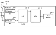
- the terminal 200-2 includes antennas 201-1 and 201-2, RF modules 290-1 and 290-2, a DSP 291-2, an MPU 292-2, and a flash memory 293-2.
- the DSP 291-2 executes, for example, a program read from the flash memory 293-2 via the MPU 292-2 based on an instruction from the MPU 292-2, so that the PHY / MAC processing units 220-1 and 220-2 Perform the function.
- the DSP 291-2 corresponds to, for example, the PHY / MAC processing units 220-1 and 220-2.
- the MPU 292-2 reads out and executes a program stored in the flash memory 293-2, for example, to thereby execute paging processing units 230-1 and 230-2, RRC processing units 240-1 and 240-2, and an IP processing unit. 250-2, the function of the WRWR information processing unit 260-2 is executed. Also, the MPU 292-2 executes the functions of the application processing unit 270-2 and the standby paging processing unit 280, for example, by executing the program.
- the MPU 292-2 includes, for example, paging processing units 230-1 and 230-2, RRC processing units 240-1 and 240-2, an IP processing unit 250-2, a WRWR information processing unit 260-2, and an application processing unit 270-2. , And the standby paging processor 280.
- RF Module 290-1 corresponds to RF processing section 210-1 in the first embodiment
- RF Module 290-2 corresponds to RF processing section 210-2 in the first embodiment
- FIG. 20 illustrates another configuration example of the wireless communication system 10.
- the wireless communication system 10 includes a first wireless communication system 11, a second wireless communication system 12, and a terminal device 200-2.
- the first wireless communication system 11 is a wireless communication system capable of communication using a communication system compatible with 5G
- the second wireless communication system 12 is a wireless communication system capable of communication using a communication system compatible with 4G.
- the first wireless communication system 11 includes a first control device 300-2 and a first base station device 100-2.
- the second radio communication system 12 includes a second control device 300-1 and a second base station device 100-1.
- the first control device 300-2 corresponds to the MME 300-2 in the first embodiment
- the first base station device 100-2 corresponds to the base station 100-2 in the first embodiment.
- the second control device 300-1 is connected to the MME 300-1 in the first embodiment
- the second base station measure 100-1 is connected to the base station 100-1 in the first embodiment.
- the first control device 300-2 includes a first notification unit 305.
- the first notification unit 305 notifies the first base station apparatus 100-2 of emergency information.
- the first base station device 100-2 includes a first transmission unit 105.
- the first transmission unit 105 transmits control information for performing standby control on the second base station device 100-1 to the terminal device 200 located in the first base station device 100-2. To -2.
- the second base station apparatus 100-1 includes a second transmission unit 106.
- the second transmission unit 106 transmits the emergency information received from the second control device 300-1 to the terminal device 200-2.
- the terminal device 200-2 includes a receiving unit 205 and a control unit 206.
- the receiving unit 205 receives the control information transmitted from the first base station device 100-2 and the emergency information transmitted from the second base station device 100-1. Further, the control unit 206 performs standby control for the second base station apparatus 100-1 based on the control information.
- the terminal apparatus 200 transmits control information for performing standby control to the second base station apparatus 100-1. -2.
- the terminal device 200-2 performs standby control on the second base station device 100-1 based on the control information, and receives emergency information from the second base station device 100-1. .
- the emergency information is not transmitted from the first base station device 100-2, and the emergency information can be received by the terminal device 200-2. Therefore, in the radio communication system 10, redundant use of radio resources is avoided as compared with the case where emergency information is transmitted from both the first base station apparatus 100-2 and the second base station apparatus 100-1. It becomes possible to do.
- the first notification unit 305 corresponds to, for example, the signaling processing unit 330-2 in the first embodiment.
- the first transmission unit 105 corresponds to, for example, the standby paging processing unit 180 in the first embodiment.
- the second transmission unit 106 corresponds to, for example, the RRC processing unit 140-1 in the first embodiment.
- the receiving unit 205 corresponds to, for example, the RF processing units 210-1 and 210-2 in the first embodiment.
- the control unit 206 corresponds to, for example, the standby paging processing unit 280 in the first embodiment.
- ETWS has been described as an example of PWS.
- CAMS instead of ETWS, it can be implemented in the same manner as in the above-described embodiment.
- the 4G-compatible base station 100-1 replaces the SIB 10 and the SIB 11 (for example, S19 and S20 in FIG. 7) with the SIB corresponding to the warning information such as the SIB 12, and the terminals 200-1 and 200-2. May be sent to.
- emergency information is mentioned in the above-described embodiment as an example of specific information
- information specified in advance including disaster information, public information, advertisement information, and the like may be used as specific information.
- the specific information may be warning message or warning message content.
- Wireless communication system 100-1 (100-2): Base station apparatus 110-1 (110-2): IP processing unit 120-1 (120-2): WRWR processing unit 130-1 (130-2): Paging processing unit 140-1 (140-2): RRC processing unit 160-1 (160-2): RF processing unit 170- 1 (170-2): S1AP processing unit 180: Standby system designation paging processing unit 185: System change processing unit 200-1 (200-2): Terminal device 210-1 (210-2): RF processing unit 230-1 (230-2): Paging processor 240-1 (240-2): RRC processor 250-1 (250-2): IP processor 260-1 (260-2): WRWR information processing unit 270-1 (270-2): Application processing unit 280: Standby system designation paging processing unit 300-1 (300-2): MME 310-1 (310-2): IP processing unit 320-1 (320-2): WRWR processing unit 330-1 (330-2): Signaling processing unit 340: System change notification unit 400: CBC 500: Japan Meteorological Agency server
Landscapes
- Engineering & Computer Science (AREA)
- Computer Networks & Wireless Communication (AREA)
- Signal Processing (AREA)
- Mobile Radio Communication Systems (AREA)
Abstract
第1の基地局装置と第1の制御装置を含む第1の無線通信システムと、第2の基地局装置と第2の制御装置を含む第2の無線通信システムと、前記第1及び第2の基地局装置と通信可能な端末装置とを備える無線通信システムにおいて、前記第1の制御装置は、前記第1の基地局装置に対して特定情報を通知する第1の通知部を備え、前記第1の基地局装置は、前記特定情報を受信したとき、前記第2の基地局装置に対して待ち受け制御を行う制御情報を前記第1の基地局装置に在圏する前記端末装置へ送信する第1の送信部を備え、前記第2の基地局装置は、前記第2の制御装置から受信した前記特定情報を前記端末装置へ送信する第2の送信部を備え、前記端末装置は、前記第1の基地局装置から送信された前記制御情報と、前記第2の基地局装置から送信された前記特定情報を受信する受信部と、前記制御情報に基づいて、前記第2の基地局装置に対して待ち受け制御を行う制御部とを備える。
Description
本発明は、無線通信システム、基地局装置、端末装置、及び特定情報送受信方法に関する。
現在、標準化団体である3GPP(3rd Generation Partnership Project)では、大容量で高速の無線ネットワークシステムの技術として、LTE(Long Term Evolution)及びLTE-Advancedの後継システムが検討されている。このようなシステムは第5世代移動通信(5G:the 5th Generation mobile communication)と呼ばれている。
また、3GPPでは、LTEシステムなどを利用したPWS(Public Warning System)の標準化も検討されている。PWSは、例えば、無線通信システムを利用して、災害や人災などの警告情報などを配信する技術である。PWSにより、例えば、警告情報などを広く公衆に対して周知させることが可能となる。
PWSを用いた配信システムとして、ETWS(Earthquake and Tsunami Warning System)やCMAS(Commercial Mobile Alert System)がある。ETWSは、例えば、地震や津波、竜巻の到来などの警告情報を端末装置へ配信するシステムである。また、CMASは、例えば、子供の誘拐や失踪、大統領メッセージなどの警告情報などを端末装置へ配信するシステムである。
このような無線通信システムに関する技術として、例えば、以下がある。すなわち、HetNet(Heterogeneous Network)において、端末が第2キャリアを用いてスモール基地局と通信を行っている場合に、第1キャリアを用いてマクロ基地局からページング情報を受信するようにしたユーザ端末に関する技術がある。
この技術によれば、HetNetにおいてスモールセル間のカバレッジホールによるネットワーク品質、或いは、それに起因するサービス品質の劣化を防止することができる、とされる。
また、特定セルのページングメッセージに基づいて他セルの報知情報の変更通知があると判定すると、他セルのページングメッセージを受信し、かつ、自セルの報知情報の変更通知があると判定すると特定セルの報知情報を受信する無線通信端末に関する技術もある。
この技術によれば、端末がキャリアアグリゲーションする場合、特定セル以外の端末のページングメッセージの受信回数を減らしつつ、必要な報知情報を端末が受信できる無線通信システムを提供することで、端末の消費電力を抑えることができる、とされる。
3GPP TS 23.041 V13.3.0 (2016-03)
そこで、一開示は、無線リソースを冗長に使用することを回避するようにした無線通信システム、基地局装置、端末装置、及び特定情報送受信方法を提供することにある。
一態様によれば、第1の基地局装置と第1の制御装置を含む第1の無線通信システムと、第2の基地局装置と第2の制御装置を含む第2の無線通信システムと、前記第1及び第2の基地局装置と通信可能な端末装置とを備える無線通信システムにおいて、前記第1の制御装置は、前記第1の基地局装置に対して特定情報を通知する第1の通知部を備え、前記第1の基地局装置は、前記特定情報を受信したとき、前記第2の基地局装置に対して待ち受け制御を行う制御情報を前記第1の基地局装置に在圏する前記端末装置へ送信する第1の送信部を備え、前記第2の基地局装置は、前記第2の制御装置から受信した前記特定情報を前記端末装置へ送信する第2の送信部を備え、前記端末装置は、前記第1の基地局装置から送信された前記制御情報と、前記第2の基地局装置から送信された前記特定情報を受信する受信部と、前記制御情報に基づいて、前記第2の基地局装置に対して待ち受け制御を行う制御部とを備える。
一開示によれば、無線リソースを冗長に使用することを回避するようにした無線通信システム、基地局装置、端末装置、及び特定情報送受信方法を提供することができる。
以下、本実施の形態について図面を参照して詳細に説明する。本明細書における課題及び実施例は一例であり、本願の権利範囲を限定するものではない。特に、記載の表現が異なっていたとしても技術的に同等であれば、異なる表現であっても本願の技術を適用可能であり、権利範囲を限定するものではない。そして、各実施の形態は、処理内容を矛盾させない範囲で適宜組み合わせることが可能である。
また、本明細書で使用している用語や記載した技術的内容は、3GPPなど通信に関する規格として仕様書に記載された用語や技術的内容が適宜用いられてもよい。このような仕様書の一例としては、3GPPで仕様化された仕様書などがある。
[第1の実施の形態]
<無線通信システムの構成例>
第1の実施の形態について説明する。図1は第1の実施の形態における無線通信システム10の構成例を表す図である。
<無線通信システムの構成例>
第1の実施の形態について説明する。図1は第1の実施の形態における無線通信システム10の構成例を表す図である。
無線通信システム10は、基地局装置(以下、「基地局」と称する場合がある。)100-1、端末装置(又はUE(User Equipment)。以下、「端末」と称する場合がある。)、MME(Mobility Management Entity)300-1、S/P-GW600-1を備える。基地局100-1と端末200-1、MME300-1、及びS/P-GW600-1は、例えば、LTEやLTE-Advancedによる通信方式を利用して通信が可能な無線通信システムとなっている。このような通信方式は、例えば、第4世代移動通信方式(4G:the 4th Generation mobile communication。以下、「4G方式」又は「4G」と称する場合がある。)と呼ばれる。従って、基地局100-1と端末200-1、MME300-1、及びS/P-GW600-1は、例えば、4G対応の基地局、MME,及びS/P-GW600-1となっている。
一方、無線通信システム10は、基地局100-2、端末200-2、MME300-2、及びS/P-GW600-2を備える。基地局100-2、端末200-2、MME300-2、及びS/P-GW600-2は、例えば、第5世代移動通信方式(以下、「5G方式」又は「5G」と称する場合がある。)を利用して通信が可能な無線通信システムとなっている。従って、基地局100-2と端末200-2、MME300-2、及びS/P-GW600-2は、5G対応の基地局、端末、MME、及びS/P-GW600-2となっている。なお、端末200-2は、4G方式と5G方式の双方に対応可能で、2つの基地局100-1,100-2と無線通信が可能となっている。
無線通信システム10は、さらに、CBC(Cell Broadcast Center)400と、気象庁サーバ500を備える。例えば、CBC400と気象庁サーバ500は、PWSシステムにおけるCBCとCBE(Cell Broadcast Entity)にそれぞれ対応する。
基地局100-1は、自局のサービス提供可能範囲に在圏する端末200-1,200-2と4G方式による無線通信を行い、端末200-1,200-2に対して様々なサービスを提供することが可能である。本第1の実施の形態では、提供サービスの一例として緊急情報の配信サービスの例を説明する。また、基地局100-1は、MME300-1との間で制御情報などを送受信し、S/P-GW600-1との間でユーザデータ(又は個別データ)などを送受信することが可能である。
基地局100-2は、自局のサービス提供可能範囲に在圏する端末200-2と5G方式による無線通信を行い、端末200-2に対して様々なサービスを提供することが可能である。基地局100-1の場合と同様に、提供サービスの一例として緊急情報の配信サービスを例にして以下説明する。また、基地局100-2は、MME300-2との間で制御情報を送受信し、S/P-GW600-2との間でユーザデータなどを送受信することが可能である。
端末200-1,200-1は、例えば、フィーチャーフォン、スマートフォン、パーソナルコンピュータ、タブレット端末、ゲーム装置などの無線通信装置である。上述したように、端末200-1は基地局100-1と4G方式(例えば、LTE方式)による無線通信を行うことが可能である。また、端末200-2は、基地局100-1と4G方式による無線通信を行い、基地局100-2と5G方式による無線通信を行うことが可能である。
MME300-1,300-2は、例えば、基地局100-1,100-2などをそれぞれ制御する制御装置である。また、MME300-1,300-2は、CBC400から送信された緊急情報を受信し、受信した緊急情報を基地局100-1,100-2へそれぞれ送信する。
MME300-1は、例えば、4G方式で規定された制御を基地局100-1やS/P-GW600-1に対して行うことが可能である。例えば、MME300-1は、端末200-1のハンドオーバ制御を行ったり、S/P-GW600-1から基地局100-1までのベアラを設定したりすることが可能である。
一方、MME300-2は、例えば、5G方式による制御を基地局100-2やS/P-GW600-2に対して行うことが可能である。この場合、MME300-2は、MME300-1と同一の処理を、基地局100-2やS/P-GW600-2に対して行うことも可能である。
CBC400は、例えば、気象庁サーバ500から送信された緊急情報を受信し、受信した緊急情報をMME300-1,300-2へ送信する。この場合、CBC400は、例えば、受信した緊急情報に基づいて、緊急情報を送信すべき地域を特定し、特定した地域に配置されたMME300-1,300-2へ緊急情報を送信することが可能である。CBC400は、例えば、モバイルネットワーク(又はコアネットワーク)に接続されたノードの1つであってもよい。
気象庁サーバ500は、例えば、緊急情報をCBC400へ送信するサーバ装置である。例えば、地震の場合、地中に埋め込まれたセンサが揺れを検出すると、その情報が気象庁サーバ500へ通知される。そして、気象庁サーバ500では、検出された揺れが一定以上の場合、地震に関する警告情報を生成し、CBC400へ送信する。
S/P-GW600-1,600-2は、例えば、S-GW(Serving Gateway)とP-GW(PDN(Packet Data Network) Gateway)を含む。S/P-GW600-1,600-2は、インターネットなどから取得したユーザデータなどを、基地局100-1,100-2へそれぞれ送信したり、基地局100-1,100-2からそれぞれ受信したユーザデータなどをインターネットへ送信したりする。この場合、S/P-GW600-1は4G方式として規定された処理を行い、S/P-GW600-2は5G方式として規定された処理を行う。
次に、無線通信システム10に含まれるMME300-1,300-2や、基地局100-1,100-2、及び端末200-1,200-2の各構成例について説明する。
<MMEの構成例>
図2はMME300-1の構成例を表している。
図2はMME300-1の構成例を表している。
MME300-1は、IP(Internet Protocol)処理部310-1と、WRWR(Write Replace Warning Request)処理部320-1、及びシグナリング処理部330-1を備える。
IP処理部310-1は、例えば、CBC400や基地局100-1,100-2とIPプロトコルによるパケットデータなどを送受信する。例えば、IP処理部310-1は、CBC400から緊急情報に関するメッセージを含むパケットデータを受信すると、パケットデータに含まれるメッセージを抽出し、抽出したメッセージをWRWR処理部320-1へ出力する。
緊急情報に関するメッセージとしては、例えば、3GPP TS36.413などで規定されたWRWRメッセージがある。WRWRメッセージは、例えば、モバイルネットワークなどにおいて緊急情報の送信を要求するメッセージである。
図15はWRWRメッセージに含まれる情報要素の例を表す。WRWRメッセージには、例えば、情報種別(地震や津波、ミサイル発射など)、再送周期、再送回数、メッセージの内容(コンテンツ)などが含まれる。WRWRメッセージは、例えば、緊急情報を受信したCBC400において、緊急情報に応じて生成されて、MME300-1へ送信される。
図2に戻り、また、IP処理部310-1は、例えば、シグナリング処理部330-1から、WRWRメッセージと、MME300-1に接続された全基地局100-1への配信指示を受け取り、受け取ったメッセージを含むパケットデータを生成して、基地局100-1へ送信する。
WRWR処理部320-1は、例えば、IP処理部310-1からWRWRメッセージを受け取り、受け取ったWRWRメッセージをシグナリング処理部330-1へ出力する。
シグナリング処理部330-1は、例えば、WRWR処理部320-1からWRWRメッセージを受け取ると、MME300-1に接続された全基地局100-1へ配信することを決定する。そして、シグナリング処理部330-1は、受け取ったWRWRメッセージをIP処理部310-1へ出力し、さらに、WRWRメッセージをMME300-1に接続された全基地局100-1へ配信するようIP処理部310-1へ指示する。シグナリング処理部330-1は、例えば、緊急情報を基地局100-1へ通知する通知部であってもよい。
図2はMME300-2の構成例も表している。MME300-2は、IP処理部310-2、WRWR処理部320-2、シグナリング処理部330-2を備える。IP処理部310-2、WRWR処理部320-2、シグナリング処理部330-2も、MME300-1におけるIP処理部310-1、WRWR処理部320-1、シグナリング処理部330-1と同様の処理を行う。
この場合、シグナリング処理部330-2は、WRWR処理部320-2からWRWRメッセージを受け取ると、MME300-2に接続された全基地局100-2に対してWRWRメッセージを配信することを決定する。そして、シグナリング処理部330-2は、WRWRメッセージを全基地局100-2へ配信することを、IP処理部310-2へ指示して、IP処理部310-2はシグナリング処理部330-2から受け取ったWRWRメッセージを全基地局100-2へ送信する。シグナリング処理部330-2も、例えば、緊急情報を基地局100-2へ通知する通知部であってもよい。
なお、IP処理部310-1,310-2とシグナリング処理部330-1,330-2は、例えば、WRWRメッセージ以外の他のメッセージについても処理可能である。このようなメッセージとしては、例えば、ハンドオーバに関するメッセージなどがある。MME300-1,300-2は、例えば、このようなメッセージを基地局100-1,100-2との間でそれぞれ交換する。
<4G対応基地局の構成例>
次に、基地局100-1の構成例について説明する。図3は基地局100-1の構成例を表す図である。なお、基地局100-1は4G対応の基地局となっている。
次に、基地局100-1の構成例について説明する。図3は基地局100-1の構成例を表す図である。なお、基地局100-1は4G対応の基地局となっている。
基地局100-1は、IP処理部110-1、WRWR処理部120-1、Paging処理部(ページング処理部)130-1、RRC(Radio Resource Control)処理部140-1を備える。また、基地局100-1は、PHY/MAC(Physical layer and MAC(Media Access Control) layer )処理部150-1、RF(Radio Frequency)処理部160-1、S1AP(S1 Application Protocol)処理部170-1、及びアンテナ101-1を備える。
IP処理部110-1は、MME300-1及びS/P-GW600-1との間でパケットデータを交換する。例えば、IP処理部110-1は、MME300-1から受信したパケットデータからWRWRメッセージを抽出し、抽出したWRWRメッセージをWRWR処理部120-1へ出力する。また、例えば、IP処理部110-1は、MME300-1から受信したWRWRメッセージ以外のメッセージを抽出し、抽出したメッセージをPaging処理部130-1やRRC処理部140-1へ出力する。さらに、IP処理部110-1は、例えば、S/P-GW600-1から受信したパケットデータからユーザデータなどを抽出し、抽出したユーザデータなどをPHY/MAC処理部150-1へ出力する。IP処理部110-1は、例えば、パケットデータに含まれるヘッダ情報に基づいて、パケットデータにどのようなメッセージなどが含まれているかを判別する。そして、IP処理部110-1は、その判別結果に従って、抽出したメッセージなどを、WRWR処理部120-1や、Paging処理部130-1とRRC処理部140-1、又はPHY/MAC処理部150-1へ出力する。
さらに、IP処理部110-1は、例えば、PHY/MAC処理部150-1からユーザデータなどを受け取り、受け取ったユーザデータを含むパケットデータを生成し、S/P-GW600-1へ送信する。
なお、IP処理部110-1は、例えば、S1AP処理部170-1を介して、MME300-1及びS/P-GW600-1との間でパケットデータを交換する。これにより、S1APのパケットデータを、MME300-1やS/P-GW600-1との間で交換可能となる。IP処理部110-1は、例えば、MME300-1から送信された緊急情報を受信する受信部であってもよい。
WRWR処理部120-1は、IP処理部110-1からWRWRメッセージを受け取ると、受け取ったWRWRメッセージを、Paging処理部130-1とRRC処理部140-1へ出力する。
Paging処理部130-1は、例えば、WRWR処理部120-1からWRWRメッセージを受け取ると、SIB(System Information Block)情報の更新を通知するPaging情報(又はページングメッセージ)を生成し、生成したPaging情報をPHY/MAC処理部150-1へ通知する。
例えば、基地局100-1はSIB情報の更新を示すPaging情報を端末200-1,200-2へ送信することで、端末200-1,200-2はSIB10やSIB11など、警告情報を含むSIBを受信することが可能となる。基地局100-1は、例えば、SIB10やSIB11を用いて警告情報を報知する。
RRC処理部140-1は、WRWR処理部120-1からWRWRメッセージを受け取ると、WRWRメッセージをSIB10とSIB11へ変換する。例えば、RRC処理部140-1は、WRWRメッセージに含まれる情報をSIB10とSIB11に振り分けるなどして、SIB10とSIB11を生成する。RRC処理部140-1は、SIB10とSIB11をPHY/MAC処理部150-1へ出力する。RRC処理部140-1は、例えば、緊急情報を在圏する端末200-1へ向けて送信する送信部であってもよい。
例えば、基地局100-1はSI(System Information)を用いて警告情報などを報知する。SIには25種類以上のSIBが定義されている。ETWSは、例えば、SIB10とSIB11が用いられる。基地局100-1は、SIB10を利用して、災害種別などを報知し、次にSIB11を利用して、災害に関する警告メッセージなどを報知する。
また、RRC処理部140-1は、例えば、端末200-1に対して無線リソースを割当てるなどスケジューリングを行い、スケジューリング結果などを含む制御情報を生成し、PHY/MAC処理部150-1へ出力する。制御情報は端末200-1へ送信される。端末200-1は割り当てられた無線リソースを利用して基地局100-1と無線通信を行って、ユーザデータ(又は個別データ)などを送受信することが可能となる。
さらに、RRC処理部140-1は、例えば、PHY/MAC処理部150-1から制御情報を受け取り、制御情報に対する処理を行い、制御情報を終端する。
PHY/MAC処理部150-1は、Paging処理部130-1から出力されたPaging情報と、RRC処理部140-1から出力された報知情報や制御情報に対して、例えば、物理層の信号(又はビット情報)に変換する。PHY/MAC処理部150-1は、変換後の信号をRF処理部160-1へ出力する。
また、PHY/MAC処理部150-1は、RF処理部160-1か出力されたベースバンド帯域の信号から、制御情報やユーザデータなどを抽出する。例えば、制御情報やユーザデータなどは予め決められたチャネルを用いて端末200-1が送信している。そのため、RF処理部160-1が無線信号を受信する際にどのチャネルを用いて受信したかを表す情報をPHY/MAC処理部150-1へ出力し、PHY/MAC処理部150-1は当該情報に基づいて、制御情報やユーザデータを抽出してもよい。PHY/MAC処理部150-1は、抽出した制御情報をRRC処理部140-1へ出力し、抽出したユーザデータなどをIP処理部110-1へ出力する。
RF処理部160-1は、PHY/MAC処理部150-1から信号を受け取ると、当該信号に対して周波数変換処理などを施して、無線帯域の無線信号に変換する。この場合、RF処理部160-1は、例えば、ベースバンド帯域から、4G方式として利用可能な周波数帯域への周波数変換を行って無線信号(以下、「4G対応無線信号」と称する場合がある。)を得る。RF処理部160-1は4G対応無線信号をアンテナ101-1へ出力する。
また、RF処理部160-1は、アンテナ101-1から出力された4G対応無線信号に対して周波数変換処理などを施して、ベースバンド帯域の信号へ変換する。RF処理部160-1は、変換後の信号をPHY/MAC処理部150-1へ出力する。この場合も、RF処理部160-1は、例えば、4G方式として利用可能な周波数帯域からベースバンド帯域への周波数変換を行うことで当該信号を得る。
アンテナ101-1は、RF処理部160-1から受け取った4G対応無線信号を端末200-1,200-2へ送信する。また、アンテナ101-1は、端末200-1,200-2から送信された4G対応無線信号を受信し、受信した4G対応無線信号をRF処理部160-1へ出力する。
S1AP処理部170-1は、例えば、IP処理部110-1からユーザデータなどを受け取り、SIAPのパケットに変換して、IP処理部110-1へ出力する。これにより、例えば、IP処理部110-1では、S1APのパケットをペイロード領域に含むIPパケットを、MME300-1やS/P-GW600-1へ送信することが可能となる。
また、S1AP処理部170-1は、例えば、IP処理部110-1からIPパケットを受け取り、IPパケットからS1APパケットに含まれるメッセージやユーザデータなどを抽出し、抽出したメッセージやユーザデータなどをIP処理部110-1へ出力する。これにより、例えば、IP処理部110-1では、MME300-1やS/P-GW600-1から送信されたパケットからメッセージやユーザデータなどを抽出することが可能となる。
<5G基地局の構成例>
次に、基地局100-2の構成例について説明する。図4は基地局100-2の構成例を表す図である。なお、基地局100-2は5G対応の基地局となっている。
次に、基地局100-2の構成例について説明する。図4は基地局100-2の構成例を表す図である。なお、基地局100-2は5G対応の基地局となっている。
基地局100-2は、IP処理部110-2、WRWR処理部120-2、Paging処理部130-2、RRC処理部140-2を備える。また、基地局100-2は、PHY/MAC処理部150-2、RF処理部160-2、S1AP処理部170-2、及びアンテナ101-2を備える。さらに、基地局100-2は、待ち受けシステム指定Paging処理部(以下、「待ち受けPaging処理部」と称する場合がある。)180を備える。
IP処理部110-2と、WRWR処理部120-2、Paging処理部130-2、RRC処理部140-2、PHY/MAC処理部150-2、RF処理部160-2、S1AP処理部170-2、及びアンテナ101-2は、例えば、基地局100-1の各ブロックとほぼ同様である。IP処理部110-2は、例えば、基地局100-1のIP処理部110-1と同様に、MME300-2から緊急情報を受信する受信部であってもよい。
ただし、IP処理部110-2では、5G対応のMME300-2とS/P-GW600-2との間でパケットデータを交換する。
また、WRWR処理部120-2は、IP処理部110-2からWRWRメッセージを受け取ると、WRWRメッセージをPaging処理部130-2とRRC処理部140-2へは出力しないで、待ち受けPaging処理部180へ出力する。そのため、基地局100-2では、在圏する端末200-2に対して、SIB10やSIB11などを用いて緊急情報を報知しないようになっている。
さらに、RF処理部160-2では、PHY/MAC処理部150-2から出力された信号を5Gで利用可能な周波数帯域の無線信号(以下、「5G対応無線信号」と称する場合がある。)へ変換して、アンテナ101-2へ出力する。さらに、RF処理部160-2では、アンテナ101-2から出力された無線信号に対して、5Gとして利用可能な周波数帯域からベースバンド帯域への周波数変換処理を施して、ベースバンド帯域の信号を抽出する。
さらに、アンテナ101-2は、5G対応無線信号を端末200-2へ送信し、端末200-2から送信された5G対応無線信号を受信する。
待ち受けPaging処理部180は、例えば、WRWR処理部120-2からWRWRメッセージを受け取ると、基地局100-2に在圏する端末200-2に対して4G方式での待ち受け制御を行わせる(又は指示する)Paging情報(又は制御情報)を生成する。このPaging情報のことを、例えば、待ち受け指定Paging情報と称する場合がある。
なお、待ち受けPaging処理部180は、例えば、端末200-2へ向けて制御情報を送信する送信部であってもよい。
図8(A)は待ち受け指定Paging情報の例を表す。待ち受け指定Paging情報には「Waiting System Change{3G,4G,reserve}」が含まれる。待ち受け指定Paging情報を受信した端末200-2は、「Waiting System Change{3G,4G,reserve}」を確認することで、5Gではなく、4G方式で待ち受けを行うよう待ち受け処理を行う。「{3G,4G}」は、例えば、待ち受け先(又は待ち受けの変更先)を表しており、5G方式から4G方式で待ち受けを行うことを表しており、さらに、4G方式が利用できない場合は、3G方式で待ち受けを行うことも表している。端末200-2において4G方式が利用できない場合は3G方式で待ち受けを行うことになる。待ち受け指定Paging情報は、例えば、5G方式の基地局100-2に対して待ち受けを行っている端末200-2に対して、基地局100-2から4G方式の基地局100-1へ待ち受けを切り替えることを指示する制御情報であってもよい。
図4に戻り、待ち受けPaging処理部180は、生成した待ち受け指定Paging情報をPHY/MAC処理部150-2へ出力する。待ち受け指定Paging情報は、端末200-2へ送信される。
<4G対応端末の構成例>
図5は、端末200-1の構成例を表している。端末200-1は、例えば、4G対応端末である。
図5は、端末200-1の構成例を表している。端末200-1は、例えば、4G対応端末である。
端末200-1は、アンテナ201-1、RF処理部210-1、PHY/MAC処理部220-1、Paging処理部230-1、RRC処理部240-1、IP処理部250-1、WRWR情報処理部260-1、及びアプリケーション処理部270-1を備える。
アンテナ201-1は、基地局100-1から送信された無線信号(4G対応無線信号)を受信し、受信した無線信号をRF処理部210-1へ出力する。また、アンテナ201-1は、RF処理部210-1から出力された無線信号(4G対応無線信号)を、基地局100-1へ送信する。
RF処理部210-1は、アンテナ201-1から出力された無線信号に対して、周波数変換処理などを施して、ベースバンド帯域の信号へ変換する。例えば、RF処理部210-1は、無線信号に対して、4Gで利用可能な周波数帯域からベースバンド帯域へ変換することで、ベースバンド帯域の信号を得る。RF処理部210-1は、変換後の信号をPHY/MAC処理部220-1へ出力する。
また、RF処理部210-1は、PHY/MAC処理部220-1から出力された信号に対して、周波数変換処理などを施して、無線帯域の無線信号へ変換する。例えば、RF処理部210-1は、ベースバンド帯域の信号を、4Gで利用可能な周波数帯域の無線信号へ変換することで、4G対応無線信号を得る。RF処理部210-1は、変換後の無線信号をアンテナ201-1へ出力する。
PHY/MAC処理部220-1は、RF処理部210-1から出力された信号から、Paging情報や報知情報、制御情報、ユーザデータなどを抽出する。例えば、Paging情報はページングチャネル、報知情報は報知チャネル、制御情報は制御チャネル、ユーザデータは共有チャネルなどを用いて基地局100-1から送信される。例えば、RF処理部210-1はどのチャネル(又は周波数)を利用して無線信号を受信したかを表す情報を、PHY/MAC処理部220-1へ出力する。PHY/MAC処理部220-1は、当該情報に基づいて、Paging情報、報知情報、制御情報、或いはユーザデータなどを抽出する。PHY/MAC処理部220-1は、例えば、Paging情報をPaging処理部230-1、報知情報や制御情報をRRC処理部240-1、ユーザデータなどをIP処理部250-1へ出力する。
また、PHY/MAC処理部220-1は、例えば、RRC処理部240-1から制御情報を受け取り、IP処理部250-1からユーザデータ(又はIPパケット)などを受け取り、制御情報やユーザデータを物理層の信号(又はビット情報)へ変換する。PHY/MAC処理部220-1は、変換後の信号をRF処理部210-1へ出力する。
Paging処理部230-1は、PHY/MAC処理部220-1から出力されたPaging情報を受け取り、受け取ったPaging情報に対する処理を行って、Paging情報を終端する。
RRC処理部240-1は、PHY/MAC処理部220-1から出力された報知情報や制御情報を受け取る。この場合、例えば、RRC処理部240-1は、SIB10とSIB11を受け取ると、SIB10とSIB11に含まれる情報(又はWRWRメッセージ)をWRWR情報処理部260-1へ出力する。
また、RRC処理部240-1は、制御情報やその他の報知情報を受け取ると、これらの情報に対応する処理を行って、制御情報とその他の報知情報を終端する。制御情報に対する処理としては、例えば、以下の処理がある。すなわち、RRC処理部240-1は、基地局100-1が端末200-1に割り当てたスケジューリング結果を制御情報から抽出する。そして、RRC処理部240-1は、抽出したスケジューリング結果に基づいて端末200-1宛のユーザデータを受信したり、抽出したりするようPHY/MAC処理部220-1やRF処理部210-1へ指示する。
IP処理部250-1は、PHY/MAC処理部220-1からユーザデータなどを受け取り、受け取ったユーザデータからIP処理を施す。例えば、PHY/MAC処理部220-1はユーザデータをIPパケットで抽出し、抽出したIPパケットをIP処理部250-1へ出力している。IP処理の例としては、IPパケットからユーザデータを抽出するなどの処理がある。IP処理部250-1は、抽出したユーザデータをアプリケーション処理部270-1へ出力する。
また、IP処理部250-1は、アプリケーション処理部270-1からユーザデータなどを受け取り、受け取ったユーザデータを含むIPパケットを生成し、PHY/MAC処理部220-1へ出力する。PHY/MAC処理部220-1では、例えば、IPパケットに対してベースバンド信号への変換を行う。
WRWR情報処理部260-1は、例えば、RRC処理部240-1から出力されたWRWR情報(又はWRWRメッセージ)から警告情報などを抽出し、アプリケーション処理部270-1へ出力する。
アプリケーション処理部270-1では、例えば、WRWR情報処理部260-1から出力された警告情報などに対して、警告音を発生させたり、端末200-1の画面上に警告メッセージをポップアップ表示させたりする。また、アプリケーション処理部270-1では、例えば、警告情報に対するアプリケーション以外にも、種々のアプリケーションを実行することも可能である。
<5G対応端末の構成例>
図6は端末200-2の構成例を表している。端末200-2は5G対応端末であるが、4Gにも対応する端末となっている。
図6は端末200-2の構成例を表している。端末200-2は5G対応端末であるが、4Gにも対応する端末となっている。
端末200-2は、アンテナ201-1、RF処理部210-1、PHY/MAC処理部220-1、Paging処理部230-1、RRC処理部240-1、IP処理部250-2、WRWR情報処理部260-2、アプリケーション処理部270-2を備える。このうち、RF処理部210-1、PHY/MAC処理部220-1、Paging処理部230-1、RRC処理部240-1における各処理は、例えば、端末200-1の各部と同様であり、4G方式に対応する。この場合、アンテナ201-1は、基地局100-1との間で無線信号(4G対応無線信号)を交換する。
また、端末200-2は、アンテナ201-2、RF処理部210-2、PHY/MAC処理部220-2、Paging処理部230-2、RRC処理部240-2、待ち受け指定Paging処理部(以下、「待ち受けPaging処理部」と称する場合がある。)280を備える。アンテナ201-2、RF処理部210-2、PHY/MAC処理部220-2、Paging処理部230-2、RRC処理部240-2は、例えば、5G方式に対応する。
アンテナ201-2は、基地局100-2との間で無線信号(5G対応無線信号)を交換する。
RF処理部210-2は、例えば、アンテナ201-2から出力された無線信号に対して周波数変換処理などを行い、5G方式で利用される周波数帯域の信号をベースバンド帯域の信号へ変換する。RF処理部210-2は、変換後の信号をPHY/MAC処理部220-2へ出力する。
また、RF処理部210-2は、例えば、PHY/MAC処理部220-2から出力された信号に対して周波数変換処理などを行い、ベースバンド帯域の信号を5G方式で利用可能な周波数帯域の無線信号(5G対応無線信号)へ変換する。RF処理部210-2は変換後の無線信号をアンテナ201-2へ出力する。
なお、2つのRF処理部210-1,210-2は、例えば、基地局100-2から送信された制御情報(例えば、待ち受け指定Paging情報)と、基地局100-1から送信された緊急情報を受信する受信部であってもよい。
PHY/MAC処理部220-2は、RF処理部210-2から出力されたベースバンド信号から、待ち受け指定Paging情報、制御情報、ユーザデータなどを抽出する。そして、PHY/MAC処理部220-2は、待ち受け指定Paging情報を待ち受けPaging処理部280、その他のPaging情報をPaging処理部230-2、制御情報などをRRC処理部240-2、ユーザデータをIP処理部250-2へそれぞれ出力する。例えば、PHY/MAC処理部220-2は、RF処理部210-2から受け取った受信チャネルに関する情報やMAC層のパケットに含まれる種別情報などに基づいて、Paging情報、制御情報、ユーザデータなどを識別して出力することが可能である。
また、PHY/MAC処理部220-2は、RRC処理部240-2から出力された制御情報や、IP処理部250-2から出力されたユーザデータ(又はIPパケット)に対して、物理層の信号(又はビット情報)へ変換する。PHY/MAC処理部220-2は、変換後の信号をRF処理部210-2へ出力する。
Paging処理部230-2は、PHY/MAC処理部220-2からPaging情報を受け取ると、Pagingに対する処理を行い、Paging情報を終端する。この場合のPaging情報は、例えば、待ち受け指定Paging情報以外のPaging情報である。
RRC処理部240-2は、例えば、PHY/MAC処理部220-2から制御情報を受け取り、制御情報に対する処理を行う。例えば、RRC処理部240-2は、制御情報に含まれるスケジューリング結果に基づいて、端末200-2宛のユーザデータを抽出するようにPHY/MAC処理部220-2へ指示するなどの処理を行う。
また、RRC処理部240-2は、例えば、制御情報を生成し、PHY/MAC処理部220-2へ出力する。
待ち受けPaging処理部280は、例えば、PHY/MAC処理部220-2から待ち受け指定Paging情報を受け取ると、端末200-2の通信状態に応じて、RRC処理部240-1,240-2に対して、待ち受けの変更を示す信号を通知する。待ち受けPaging処理部280は、例えば、基地局100-1に対して待ち受け制御を行う制御部であってもよい。例えば、待ち受けPaging処理部280は以下の処理を行う。
すなわち、端末200-2が5G側で待ち受け中のとき、待ち受けPaging処理部280は、待ち受け指定Paging情報を受信すると、4G対応のRRC処理部240-1に対して、待ち受けを行うことを指示する信号を出力する。また、待ち受けPaging処理部280は、5G対応のRRC処理部240-2に対して待ち受けを停止することを指示する信号を出力する。
具体的には、待ち受けPaging処理部280は、待ち受け指定Paging情報に含まれるSIBの変更、ETWSの指示などの情報を含む信号を、RRC処理部240-1へ通知出力。RRC処理部240-1は、このような信号に基づいて、RF処理部210-1とPHY/MAC処理部220-1に対して、SIB10とSIB11を受信できるタイミングや受信周波数などを通知する。これにより、RF処理部210-1とPHY/MAC処理部220-1は、基地局100-1から送信された無線信号からSIB10とSIB11を受信し、RRC処理部240-1へ出力することが可能となる。そして、RRC処理部240-1では、基地局100-1に対して待ち受け中に、SIB10とSIB11を受信することが可能となる。
或いは、端末200-2が5G側で通信中のとき、待ち受けPaging処理部280は、5G側の通信を維持した状態で、4G側の待ち受けを新たに追加するようにしてもよい。この場合も、待ち受けPaging処理部280は、待ち受け指定Paging情報を受信すると、待ち受け指定Paging情報に含まれる情報を含む信号をRRC処理部240-1へ出力するなどして、RRC処理部240-1に対して待ち受けを指示する。この場合は、待ち受けPaging処理部280は、RRC処理部240-2に対してとくに信号を出力することなく、状態を維持させるようにする。待ち受け指定Paging情報は、例えば、基地局100-2と通信を行っている端末200-2に対して、基地局100-1に対する待ち受けを追加することを指示する制御情報であってもよい。
上記した例は、端末200-2において4G側の待ち受けの変更又は追加を制御する例を説明した。例えば、待ち受け指定Paging情報に、待ち受けの変更又は追加が指示されてもよい。例えば、基地局100-2の待ち受けPaging処理部180が変更又は追加を示す情報を含む待ち受け指定Paging情報を生成して端末200-2へ送信する。端末200-2の待ち受けPaging処理部280は、例えば、当該情報に基づいて、RRC処理部240-2に対して停止、RRC処理部240-1に対して待ち受けを指示する。また、待ち受けPaging処理部280は、例えば、当該情報に基づいて、RRC処理部240-2に対して指示を行うことなく、RRC処理部240-1に対して待ち受けを指示する。
IP処理部250-2は、例えば、アプリケーション処理部270-2から出力されたユーザデータなどに対して、当該ユーザデータなどを含むIPパケットを生成し、PHY/MAC処理部220-1又はPHY/MAC処理部220-2へ出力する。また、IP処理部250-2は、例えば、PHY/MAC処理部220-1,220-2から出力されたIPパケットなどに対して、ユーザデータなどを抽出し、抽出したユーザデータをアプリケーション処理部270-2へ出力する。
WRWR情報処理部260-2は、例えば、RRC処理部240-1から出力されたWRWR情報から警告情報などを抽出し、アプリケーション処理部270-2へ出力する。
アプリケーション処理部270-2は、例えば、WRWR情報処理部260-2から出力された警告情報などに対して、警告音を発生させたり、端末200-2の画面上に警告メッセージをポップアップ表示させたりする。また、アプリケーション処理部270-2は、例えば、警告情報に対するアプリケーション以外にも、種々のアプリケーションを実行することも可能である。
<動作例>
次に動作例について説明する。図7は無線通信システム10におけるシーケンス例を表している。図7は、例えば緊急地震情報を報知する場合の例である。
次に動作例について説明する。図7は無線通信システム10におけるシーケンス例を表している。図7は、例えば緊急地震情報を報知する場合の例である。
気象庁サーバ500は、例えば、地震を検知すると、緊急地震速報を生成し、CBC400へ送信する(S10)。この場合、気象庁サーバ500は、緊急地震速報を報知する地域を示す地域情報を、緊急地震速報に含ませる。
CBC400は、緊急地震速報を受信すると、WRWRメッセージを生成し、生成したWRWRメッセージを4G対応のMME300-1と5G対応のMME300-2へ送信する(S11,S12)。例えば、CBC400は、緊急地震速報に含まれる地域情報に基づいて、当該地域に配置されたMME300-1,300-2へWRWRメッセージを送信する。
MME300-1は、WRWRメッセージを受信すると、受信したWRWRメッセージを配下の全基地局100-1へ送信する(S13)。
また、MME300-2も、WRWRメッセージを受信すると、受信したWRWRメッセージを配下の全基地局100-2へ送信する(S14)。
そして、5G対応の基地局100-2は、WRWRメッセージを受信すると、待ち受け指定Paging情報を生成し、生成した待ち受け指定Paging情報を在圏する端末200-2へ送信する(S15)。例えば、待ち受けPaging処理部180が、WRWR処理部120-2からWRWRメッセージを受け取ると、待ち受け指定Paging情報を生成し、生成した待ち受け指定Paging情報を、PHY/MAC処理部150-2などを介して、端末200-2へ送信する。
図8(A)は待ち受け指定Paging情報の例を表している。上述したように、待ち受けPaging指定情報には「Waiting System Change{3G,4G,reserve}」が含まれる。
待ち受けPaging指定情報に含まれるそれ以外の情報要素は、例えば、SIBの変更を表す情報要素を含む。例えば、「sysmtenInfoModification」はSIBの変更を示す情報要素であり、「etws-Indication」はETWSを指示する情報要素である。例えば、このような情報要素を含むPaging情報を受信した端末200-1,200-2は、受信タイミングや受信周波数を調整して、SIB10とSIB11(又は緊急情報)を受信可能なようにし、SIB10とSIB11の受信を待機する。
例えば、待ち受けPaging指定情報(又は制御情報)は「Waiting System Change{3G,4G,reserve}」であってもよい。この場合、例えば、基地局100-2は、SIB変更を示すPaging情報に待ち受けPaging指定情報を含めて送信する、としてもよい。
図7に戻り、端末200-2は、基地局100-2から待ち受け指定Paging情報を受信すると、5G対応の基地局100-2から4G対応の基地局100-2へ、待ち受けを変更する(S16)。例えば、待ち受けPaging処理部280は、PHY/MAC処理部220-2から待ち受け指定Paging情報を受け取ると、RRC処理部240-1に対して待ち受けを行うよう指示する。この場合、待ち受けPaging処理部280は、例えば、5Gから4Gへの待ち受けの変更を行ってもよいし、5Gの待ち受けに対して4Gの待ち受けを追加するようにしてもよい。
一方、4G対応の基地局100-1は、WRWRメッセージを受信すると、SIBの変更などを含むPaging情報を生成し、在圏する端末200-1,200-2へ送信する(S17,18)。例えば、Paging処理部130-1がSIB変更を含むPaging情報を生成し、生成したPaging情報をPHY/MAC処理部150-1などを介して端末200-1,200-2へ送信する。
次に、4G対応の基地局100-1は、SIB10とSIB11を在圏する端末200-1,200-2へ報知する(S19,S20)。例えば、RRC処理部140-1がSIB10とSIB11を生成し、PHY/MAC処理部150-1などを介して、端末200-1,200-2へ報知する。
端末200-2は、待ち受け指定Paging情報を受信することで(S15)、4G対応の基地局100-1に対して待ち受けを行っており(S16)、基地局100-1から報知されたSIB10とSIB11を受信することができる(S19,S20)。
図9は、無線通信システム10におけるシーケンス例を表している。図9の例では、5G対応の基地局100-2は、MME300-1からWRWRメッセージを受信しても待ち受け指定Paging情報を送信するのではなく、4G対応の基地局100-1と同様に、SIBの変更などを含むPaging情報を端末200-2へ送信している(S30,S32)。そして、基地局100-2は、基地局100-1と同様に、SIBを用いて、緊急情報を報知している(S31,S33)。
この場合、2つの基地局100-1,100-2は、緊急地震速報に関する同一のメッセージを報知している(S31,S33)。
一方、図7に示す例では、基地局100-1が緊急地震速報に関するメッセージを送信し(S19,S20)、基地局100-2はこのようなメッセージを送信していない。従って、図7に示す無線通信システム10においては、図9の例と比較して、無線リソースを冗長に使用していない。よって、本無線通信システム10では、無線リソースの冗長使用を回避することが可能となっている。
例えば、5G方式については3GPPにおいて現在、検討段階ではあるものの、4G方式と比較して、サービス提供エリア(又は通信可能エリア)が狭くなることが予想される。その場合、5G方式の端末200-2は、4G方式の端末200-1と比較して、緊急情報などを受信する確率が低くなることも予想される。従って、本無線通信システム10に示すように、5G方式の端末200-2であっても、4G方式によるサービス提供エリアを利用して4G対応の基地局100-1から送信された緊急情報を受信することで、緊急情報を受信する可能性を高めることが可能となる。
[第2の実施の形態]
次に第2の実施の形態について説明する。第2の実施の形態は、待ち受け指定Paging情報にタイマーが指定される例である。例えば、端末200-2は、4G対応の基地局100-2に対する待ち受けを開始後、タイマーで指定された時間経過すると、5G対応の基地局100-24Gへ、待ち受け状態を戻すようする。
次に第2の実施の形態について説明する。第2の実施の形態は、待ち受け指定Paging情報にタイマーが指定される例である。例えば、端末200-2は、4G対応の基地局100-2に対する待ち受けを開始後、タイマーで指定された時間経過すると、5G対応の基地局100-24Gへ、待ち受け状態を戻すようする。
図10は第2の実施の形態におけるシーケンス例を表している。
基地局100-2は、MME300-2からWRWRメッセージを受信すると(S14)、タイマーを含む待ち受け指定Paging情報を生成し、端末200-2へ送信する(S41)。
タイマーは、例えば、ETWSやCMASなどで要求されている要求値に応じた時間としてもよい。図11は要求値の例を表している。図11の例では、ETWSの場合、基地局100-2がMME300-2からWRWRメッセージを受信後、端末200-2へSIB10とSIB11を送信するまでの時間は4sec以内であることが要求されている。また、CMASの場合、基地局100-2がMME300-2からメッセージを受信後、端末200-2へSIB12を送信するまでの時間は60sec以内であることが要求されている。待ち受けPaging処理部180は、例えば、基地局100-2がMME300-2からWRWRメッセージを受信後、SIB10とSIB11を送信するまでにかかる時間に応じたタイマー値を設定する。
例えば、待ち受けPaging処理部180は、以下の処理を行う。すなわち、待ち受けPaging処理部180は、WRWR処理部120-2からWRWRメッセージに含まれる情報を受け取り、当該情報に基づいて、タイマー値を設定する。例えば、待ち受けPaging処理部180は、当該情報に含まれるメッセージ内容に基づいて、ETWSに関するメッセージのときはタイマー値を4secに設定し、CAMSに関するメッセージのときはタイマー値を60secに設定する。待ち受けPaging処理部180は設定したタイマー値を含む待ち受け指定Paging情報を生成し、端末200-2へ向けて送信する。
図8(B)はタイマー値を含む待ち受け指定Paging情報の例を表している。待ち受け指定Paging情報には、情報要素として、更に、「Timer{1,4,…,60}」を含む。「Timer{1,4,…,60}」が、例えば、タイマー値を表している。この例では、タイマー値として1sec、4sec、…、60secが選択可能となっている。すなわち、端末200-2はタイマー値を含む待ち受け指定Paging情報を受信すると、当該情報に含まれる他の情報要素を参照して、タイマー値を選択し、選択したタイマー時間が経過すると、元の状態に戻すようになっている。
例えば、端末200-2では以下の処理を行う。すなわち、待ち受けPaging処理部280は、PHY/MAC処理部220-2から、タイマー値を含む待ち受け指定Paging情報を受け取ると、当該情報に含まれる情報要素に基づいて、タイマー値を選択する。例えば、待ち受けPaging処理部280は、ETWSを指示する情報要素が含まれるときは4secを選択し、CMASを指示する情報要素が含まれるときは60secを選択するなどである。そして、待ち受けPaging処理部280は、RRC処理部240-1に対して待ち受けを指示した時間(又はタイマー値を含む待ち受け指定Paging情報を受信した時間)からタイマー時間のカウントを開始し、その時間が経過すると、RRC処理部240-1に対して、4Gの待ち受けを終了するように指示する。これにより、端末200-2は、タイマー時間経過後、タイマー値を含む待ち受け指定Paging情報を受信する前の待ち受け状態に戻ることが可能となる。
タイマー値は、例えば、端末200-2が基地局100-1に対する待ち受け制御を行っている時間、或いは、端末200-2が基地局100-1に対する待ち受け制御を開始してから、基地局100-2に対する待ち受け制御へ戻るまでの時間、を表している。
[第3の実施の形態]
次に第3の実施の形態について説明する。
次に第3の実施の形態について説明する。
図12は第3の実施の形態における無線通信システム10のシーケンス例を表している。この場合もETWSにおいて緊急地震速報を報知する場合の例となっている。
5G対応のMME300-1は、CBC400からWRWRメッセージを受信すると(S12)、WRWRメッセージを基地局100-2へ送信するのではなく(又はWRWRメッセージの送信に代えて)、システム変更メッセージを基地局100-2へ送信する(S50)。5G対応の基地局100-2は、システム変更メッセージを受信すると、第1の実施の形態と同様に、待ち受け指定Paging情報を端末200-2へ送信する(S15)。すなわち、システム変更メッセージは、例えば、待ち受けの変更を表す(又は指示する)メッセージとなっている。
図15は、MME300-1,300-2が基地局100-1,100-2へ送信するWRWRメッセージに含まれる情報要素の例を表している。第1の実施の形態では、MME300-2は、例えば、このような情報要素を含むWRWRメッセージを基地局100-2へ送信する。
一方、図16は、本第3の実施の形態において、MME300-2が基地局100-2へ送信するシステム変更メッセージに含まれる情報要素の例を表している。図15と図16を比較して明らかなように、システム変更メッセージに含まれる情報要素は、WRWRメッセージに含まれる情報要素よりも少ない。例えば、MME300-2は多くの基地局100-2と接続している場合、WRWRメッセージの送信量も基地局100-2の台数に応じて多くなる。しかし、MME300-2は、WRWRメッセージに代えてシステム変更メッセージを送信することで、メッセージの送信量を少なくさせ、情報量の削減を図ることが可能となる。
なお、図16において「Message Type」は、例えば、メッセージの種別を示し、システム変更メッセージであることを示す種別情報が含まれる。「Warining Area List」は、例えば、システム変更メッセージの配信エリアを示す情報が含まれる。「System Change」は、例えば、待ち受けの移動先(又は変更先)を表し、図16の例では、4Gや3G、GSM(登録商標)(Global System for Mobile communications)となっている。さらに、「System Change Timer」は、例えば、待ち受けの変更を行う時間(sec)を表す。この時間は、例えば、第2の実施の形態と同様の時間となっている。なお、図16の例では、「Warining Area List」と「System Change Timer」の各情報要素はオプションとなっており、この情報要素がシステム変更メッセージに含まれてもよいし、含まれなくてもよい。
図13は、本第3の実施の形態におけるMME300-2の構成例を表している。MME300-2は、更に、システム変更通知部340を備える。
システム変更通知部340は、例えば、シグナリング処理部330-2からWRWRメッセージを受け取ると、システム変更メッセージ(例えば図16)を生成し、IP処理部310-2を介して基地局100-2へ送信する。例えば、IP処理部310-2は、S1APのパケットをペイロード領域に含むIPパケットを生成して、基地局100-2へ送信してもよい。S1APのパケットには、例えば、図16に示す情報要素が挿入される。
図12に戻り、基地局100-2は、システム変更メッセージを受信すると、第1の実施の形態と同様に、待ち受け指定Paging情報を端末200-2へ送信する(S15)。
図14は、本第3の実施の形態における基地局100-2の構成例を表している。基地局100-2は、更に、システム変更処理部185を備える。
システム変更処理部185は、例えば、IP処理部110-2からシステム変更メッセージを受け取ると、システム変更メッセージに含まれる情報要素(例えば、「System Change」と「System Change Timer」)を抽出し、待ち受けPaging処理部180へ出力する。或いは、システム変更処理部185は、受け取ったシステム変更メッセージを待ち受けPaging処理部180へ出力してもよい。
待ち受けPaging処理部180は、例えば、情報要素の通知を受けて、待ち受けの変更先の情報を含む待ち受け指定Paging情報を生成する。或いは、待ち受けPaging処理部180は、システム変更処理部185から受け取ったシステム変更メッセージに基づいて、情報要素を抽出し、抽出した情報要素を含む待ち受け指定Paging情報を生成して、端末200-2へ送信してもよい。
また、待ち受けPaging処理部180は、例えば、情報要素の通知を受けて、第2の実施の形態と同様に、タイマー値を含む待ち受け指定Paging情報を生成してもよい。
[その他の実施の形態]
次に、その他の実施の形態について説明する。
次に、その他の実施の形態について説明する。
図17(A)から図19は、無線通信システム10に含まれる各装置のハードウェア構成例を表している。
図17(A)はMME300-1のハードウェア構成例を表している。MME300-1は、CPU(Central Processing Unit)390-1、HDD(Hard Disk Drive)391-1、IF(Interface)392-1を備える。CPU390は、例えば、HDD391-1などに記憶されたプログラムを読み出して実行することで、第1の実施の形態で説明したWRWR処理部320-1とシグナリング処理部330-1の機能を実行する。CPU390-1は、例えば、WRWR処理部320-1とシグナリング処理部330-1に対応する。また、IF392-1は、例えば、第1の実施の形態におけるIP処理部310-1に対応する。
なお、図17(A)はMME300-2のハードウェア構成例を表している。この場合、MME300-2は、CPU390-2、HDD391-2、及びIF392-2を備える。CPU390-2も、例えば、HDD391-2に記憶されたプログラムを読み出して実行することで、第1の実施の形態で説明したWRWR処理部320-2とシグナリング処理部330-2、及び第3の実施の形態で説明したシステム変更通知部340の機能を実行する。CPU390-2は、例えば、WRWR処理部320-2とシグナリング処理部330-2、及びシステム変更通知部340に対応する。また、IF392-2は、例えば、第1の実施の形態におけるIP処理部310-2に対応する。
図17(B)は基地局100-1のハードウェア構成例を表している。基地局100-1は、アンテナ101-1、RF module190-1、DSP(Digital Signal Processor)191-1、MPU(Micro-Processing Unit)192-1、IF193-1、及びメモリ194-1を備える。
DSP191-1は、例えば、メモリ194-1に記憶されたプログラムを読み出して実行することで、第1の実施の形態で説明したPHY/MAC処理部150-1の機能を実行する。DSP191-1は、例えば、PHY/MAC処理部150-1に対応する。
また、MPU192-1も、例えば、メモリ194-1に記憶されたプログラムを読み出して実行することで、第1の実施の形態で説明したWRWR処理部120-1、Paging処理部130-1、RRC処理部140-1、及びS1AP処理部170-1の機能を実行する。MPU192-1は、例えば、WRWR処理部120-1、Paging処理部130-1、RRC処理部140-1、及びS1AP処理部170-1に対応する。
さらに、RF Module190-1は、例えば、第1の実施の形態におけるRF処理部160-1に対応する。また、IF193-1は、例えば、第1の実施の形態におけるIP処理部110-1に対応する。
図18(A)は基地局100-2のハードウェア構成例を表している。基地局100-2は、アンテナ101-2、RF Module190-2、DSP191-2、MPU192-2、IF193-2、及びメモリ194-2を備える。
DSP191-2は、例えば、メモリ194-2に記憶されたプログラムを読み出して実行することで、第1の実施の形態で説明したPHY/MAC処理部150-2の機能を実行する。DSP191-2は、例えば、PHY/MAC処理部150-2に対応する。
また、MPU192-2も、例えば、メモリ194-2に記憶されたプログラムを読み出して実行することで、第1の実施の形態で説明した、WRWR処理部120-2、Paging処理部130-2、RRC処理部140-2、S1AP処理部170-2、待ち受けPaging処理部180の機能を実行する。また、MPU192-2は、当該プログラムを実行することで、第2の実施の形態で説明したシステム変更処理部185の機能を実行する。MPU192-2は、例えば、WRWR処理部120-2、Paging処理部130-2、RRC処理部140-2、S1AP処理部170-2、待ち受けPaging処理部180、及びシステム変更処理部185に対応する。
さらに、RF Module190-2は、例えば、第1の実施の形態におけるRF処理部160-2に対応する。また、IF193-2は、例えば、第1の実施の形態におけるIP処理部110-2に対応する。
図18(B)は端末200-1のハードウェア構成例を表している。端末200-1は、アンテナ201-1、RF Module290-1、DSP291-1、MPU292-1、フラッシュメモリ293-1を備える。
DSP291-1は、例えば、MPU292-1からの指示に基づいて、MPU292-1を介してフラッシュメモリ293-1に記憶されたプログラムを読み出して実行することで、第1の実施の形態で説明したPHY/MAC処理部220-1の機能を実行する。DSP291-1は、例えば、PHY/MAC処理部220-1に対応する。
MPU292-1は、例えば、フラッシュメモリ293-1に記憶されたプログラムを読み出して実行することで、第1の実施の形態で説明した、Paging処理部230-1、RRC処理部240-1の機能を実行する。また、MPU292-1は、例えば、当該プログラムを実行することで、IP処理部250-1、WRWR情報処理部260-1、アプリケーション処理部270-1機能を実行する。MPU292-1は、例えば、Paging処理部230-1、RRC処理部240-1、IP処理部250-1、WRWR情報処理部260-1、及びアプリケーション処理部270-1に対応する。
また、RF Module290-1は、例えば、第1の実施の形態におけるRF処理部210-1に対応する。
図19は端末200-2のハードウェア構成例を表している。端末200-2は、アンテナ201-1,201-2、RF Module290-1,290-2、DSP291-2、MPU292-2、フラッシュメモリ293-2を備える。
DSP291-2は、例えば、MPU292-2からの指示に基づいて、MPU292-2を介してフラッシュメモリ293-2から読み出したプログラムを実行することで、PHY/MAC処理部220-1,220-2の機能を実行する。DSP291-2は、例えば、PHY/MAC処理部220-1,220-2に対応する。
MPU292-2は、例えば、フラッシュメモリ293-2に記憶されたプログラムを読み出して実行することで、Paging処理部230-1,230-2、RRC処理部240-1,240-2、IP処理部250-2、WRWR情報処理部260-2の機能を実行する。また、MPU292-2は、例えば、当該プログラムを実行することで、アプリケーション処理部270-2、及び待ち受けPaging処理部280の機能を実行する。MPU292-2は、例えば、Paging処理部230-1,230-2、RRC処理部240-1,240-2、IP処理部250-2、WRWR情報処理部260-2、アプリケーション処理部270-2、及び待ち受けPaging処理部280に対応する。
また、例えば、RF Module290-1は第1の実施の形態におけるRF処理部210-1、RF Module290-2は第1の実施の形態のけるRF処理部210-2にそれぞれ対応する。
図20は無線通信システム10の他の構成例を表している。無線通信システム10は、第1の無線通信システム11と第2の無線通信システム12、及び端末装置200-2を備える。
例えば、第1の無線通信システム11は5G対応の通信方式により通信可能な無線通信システムであり、第2の無線通信システム12は4G対応の通信方式により通信可能な無線通信システムである。
第1の無線通信システム11は、第1の制御装置300-2と第1の基地局装置100-2を含む。また、第2の無線通信システム12は、第2の制御装置300-1と第2の基地局装置100-1を含む。
例えば、第1の制御装置300-2は、第1の実施の形態におけるMME300-2、第1の基地局装置100-2は、第1の実施の形態における基地局100-2にそれぞれ対応する。また、例えば、第2の制御装置300-1は、第1の実施の形態におけるMME300-1、第2の基地局措置100-1は、第1の実施の形態における基地局100-1にそれぞれ対応する。
第1の制御装置300-2は第1の通知部305を備える。第1の通知部305は、第1の基地局装置100-2に対して緊急情報を通知する。
第1の基地局装置100-2は第1の送信部105を備える。第1の送信部105は、緊急情報を受信したとき、第2の基地局装置100-1に対して待ち受け制御を行う制御情報を第1の基地局装置100-2に在圏する端末装置200-2へ送信する。
第2の基地局装置100-1は第2の送信部106を備える。第2の送信部106は第2の制御装置300-1から受信した緊急情報を端末装置200-2へ送信する。
端末装置200-2は、受信部205と制御部206を備える。受信部205は、第1の基地局装置100-2から送信された制御情報と、第2の基地局装置100-1から送信された緊急情報を受信する。また、制御部206は、制御情報に基づいて、第2の基地局装置100-1に対して待ち受け制御を行う。
このように、本無線通信システム10においては、第1の基地局装置100-2は緊急情報を受信すると、第2の基地局装置100-1に対して待ち受け制御を行う制御情報を端末装置200-2へ送信している。この場合、端末装置200-2では、制御情報に基づいて、第2の基地局装置100-1に対して待ち受け制御を行い、第2の基地局装置100-1から緊急情報を受信している。そして、第1の基地局装置100-2から緊急情報は送信されることなく、端末装置200-2において緊急情報を受信することができるようになっている。従って、本無線通信システム10では、緊急情報が第1の基地局装置100-2と第2の基地局装置100-1の双方から送信される場合と比較して、無線リソースの冗長使用を回避することが可能となる。
なお、第1の通知部305は、例えば、第1の実施の形態におけるシグナリング処理部330-2に対応する。また、第1の送信部105は、例えば、第1の実施の形態における待ち受けPaging処理部180に対応する。さらに、第2の送信部106は、例えば、第1の実施の形態におけるRRC処理部140-1に対応する。さらに、受信部205は、例えば、第1の実施の形態におけるRF処理部210-1,210-2に対応する。さらに、制御部206は、例えば、第1の実施の形態における待ち受けPaging処理部280に対応する。
上述した実施の形態においては、PWSの例として、ETWSを例にして説明した。例えば、ETWSに代えてCAMSによる警告情報の報知であっても、上述した実施の形態と同様に実施可能である。この場合、気象庁サーバ500に代えて、緊急情報を配信するサーバでとなり、このようなサーバから、例えば、ミサイル発射や大統領メッセージなどの警告情報が送信される。また、この場合、4G対応の基地局100-1は、SIB10とSIB11(例えば図7のS19,S20)に代えて、SIB12など、警告情報に対応したSIBを、端末200-1,200-2へ送信してもよい。
なお、特定情報の一例として、上述した実施の形態では緊急情報を挙げているが、それ以外にも、災害情報や公共情報、宣伝情報などを含む、あらかじめ規定された情報を特定情報としてもよい。また、特定情報は、warning message、又は、warning message contentであってもよい。
10:無線通信システム
100-1(100-2):基地局装置
110-1(110-2):IP処理部
120-1(120-2):WRWR処理部
130-1(130-2):Paging処理部
140-1(140-2):RRC処理部
160-1(160-2):RF処理部
170-1(170-2):S1AP処理部
180:待ち受けシステム指定Paging処理部
185:システム変更処理部
200-1(200-2):端末装置
210-1(210-2):RF処理部
230-1(230-2):Paging処理部
240-1(240-2):RRC処理部
250-1(250-2):IP処理部
260-1(260-2):WRWR情報処理部
270-1(270-2):アプリケーション処理部
280:待ち受けシステム指定Paging処理部
300-1(300-2):MME
310-1(310-2):IP処理部
320-1(320-2):WRWR処理部
330-1(330-2):シグナリング処理部
340:システム変更通知部 400:CBC
500:気象庁サーバ
100-1(100-2):基地局装置
110-1(110-2):IP処理部
120-1(120-2):WRWR処理部
130-1(130-2):Paging処理部
140-1(140-2):RRC処理部
160-1(160-2):RF処理部
170-1(170-2):S1AP処理部
180:待ち受けシステム指定Paging処理部
185:システム変更処理部
200-1(200-2):端末装置
210-1(210-2):RF処理部
230-1(230-2):Paging処理部
240-1(240-2):RRC処理部
250-1(250-2):IP処理部
260-1(260-2):WRWR情報処理部
270-1(270-2):アプリケーション処理部
280:待ち受けシステム指定Paging処理部
300-1(300-2):MME
310-1(310-2):IP処理部
320-1(320-2):WRWR処理部
330-1(330-2):シグナリング処理部
340:システム変更通知部 400:CBC
500:気象庁サーバ
Claims (18)
- 第1の基地局装置と第1の制御装置を含む第1の無線通信システムと、
第2の基地局装置と第2の制御装置を含む第2の無線通信システムと、
前記第1及び第2の基地局装置と通信可能な端末装置と
を備える無線通信システムにおいて、
前記第1の制御装置は、
前記第1の基地局装置に対して特定情報を通知する第1の通知部
を備え、
前記第1の基地局装置は、
前記特定情報を受信したとき、前記第2の基地局装置に対して待ち受け制御を行う制御情報を前記第1の基地局装置に在圏する前記端末装置へ送信する第1の送信部
を備え、
前記第2の基地局装置は、
前記第2の制御装置から受信した前記特定情報を前記端末装置へ送信する第2の送信部
を備え、
前記端末装置は、
前記第1の基地局装置から送信された前記制御情報と、前記第2の基地局装置から送信された前記特定情報を受信する受信部と、
前記制御情報に基づいて、前記第2の基地局装置に対して待ち受け制御を行う制御部と
を備えることを特徴とする無線通信システム。 - 前記第1の送信部は、前記第1の基地局装置に対して待ち受け制御を行っている前記端末装置に対して、前記第1の基地局装置から前記第2の基地局装置へ待ち受け制御を切り替える前記制御情報を送信することを特徴とする請求項1記載の無線通信システム。
- 前記第1の送信部は、前記第1の基地局装置と通信を行っている前記端末装置に対して、前記第2の基地局装置に対する待ち受け制御を行うことを追加する前記制御情報を送信することを特徴とする請求項1記載の無線通信システム。
- 前記第1の送信部は、前記第2の基地局装置に対して待ち受け制御を行う時間を含む前記制御情報を送信することを特徴とする請求項1記載の無線通信システム。
- 前記第1の制御装置は、更に、前記特定情報の送信に代えて、待ち受けの変更を表すシステム変更メッセージを前記第1の基地局装置へ送信するシステム変更通知部を備え、
前記第1の基地局装置は、前記第1の制御装置から受信した前記システム変更メッセージを前記第1の送信部へ出力するシステム変更処理部を備え、
前記第1の送信部は、前記システム変更メッセージに基づいて前記制御情報を送信することを特徴とする請求項1記載の無線通信システム。 - 前記第1の無線通信システムに含まれる前記第1の基地局装置と前記第1の制御装置は第1の通信方式を利用して通信を行い、前記第2の無線通信システムに含まれる前記第2の基地局装置と前記第2の制御装置は第2の通信方式を利用して通信を行うことを特徴とする請求項1記載の無線通信システム。
- 前記第1の無線通信システムに含まれる前記第1の基地局装置と前記第1の制御装置は第5世代移動通信方式による通信方式を利用して通信を行い、前記第2の無線通信システムに含まれる前記第2の基地局装置と前記第2の制御装置は第4世代移動通信方式による通信方式を利用して通信を行うことを特徴とする請求項1記載の無線通信システム。
- 前記第2の送信部は、前記特定情報を報知情報として送信し、
前記第1の送信部は、前記報知情報の変更を表すページング情報に前記制御情報を含めて前記ページング情報を前記端末装置へ送信することを特徴とする請求項1記載の無線通信システム。 - 前記第2の送信部は、前記特定情報をSIB(System Information Block)を利用して送信し、
前記第1の送信部は、前記SIBの変更を表すページング情報に前記制御情報を含めて前記ページング情報を前記端末装置へ送信することを特徴とする請求項1記載の無線通信システム。 - 前記制御部は、前記制御情報に基づいて、前記第2の基地局装置から送信される前記特定情報を待ち受けることを指示する信号を前記受信部へ出力することを特徴とする請求項1記載の無線通信システム。
- 前記受信部は、前記制御情報を含む報知情報の変更を表すページング情報を受信し、
前記制御部は、前記ページング情報と前記制御情報に基づいて、前記第2の基地局装置から報知情報として送信される前記特定情報を待ち受けることを指示する信号を前記受信部へ出力することを特徴とする請求項1記載の無線通信システム。 - 前記受信部は、前記制御情報を含むSIB(System Information Block)の変更を表すページング情報を受信し、
前記制御部は、前記ページング情報と前記制御情報に基づいて、前記第2の基地局装置からSIBを利用して送信される前記特定情報を待ち受けることを指示する信号を前記受信部へ出力することを特徴とする請求項1記載の無線通信システム。 - 前記第2の基地局装置に対して待ち受け制御を行う時間は、前記第2の基地局装置が前記第2の制御装置から前記特定情報を受信後、前記特定情報を前記端末装置へ送信するまでに時間に対応した時間であることを特徴とする請求項4記載の無線通信システム。
- 前記システム変更通知部は、前記システム変更メッセージをS1AP(S1 Application Protocol)を利用して送信することを特徴とする請求項5記載の無線通信システム。
- 前記システム変更通知部は、前記システム変更メッセージであることを示す識別情報と、待ち受け制御の変更先を示す情報を含む前記システム変更メッセージを送信することを特徴とする請求項5記載の無線通信システム。
- 端末装置と通信可能であって、無線通信システムに含まれる基地局装置において、
前記無線通信システムに含まれる制御装置から特定情報を受信する受信部と、
前記特定情報を受信したとき、他の無線通信システムに含まれる他の基地局装置に対して待ち受け制御を行う制御情報を前記基地局装置に在圏する前記端末装置へ送信する送信部と
を備えることを特徴とする基地局装置。 - 無線通信システムに含まれる基地局装置と通信可能な端末装置において、
他の無線通信システムに含まれる他の基地局装置に対して待ち受け制御を行う制御情報と、前記他の基地局装置から送信された特定情報とを、前記基地局装置から受信する受信部と、
前記制御情報に基づいて、前記他の基地局装置に対する待ち受け制御を行う制御部と
を備えることを特徴とする端末装置。 - 第1の基地局装置と第1の制御装置を含む第1の無線通信システムと、第2の基地局装置と第2の制御装置を含む第2の無線通信システムと、前記第1及び第2の基地局装置と通信可能な端末装置とを備える無線通信システムにおける特定情報送受信方法であって、
前記第1の制御装置により、前記第1の基地局装置に対して特定情報を通知し、
前記第1の基地局装置により、前記特定情報を受信したとき、前記第2の基地局装置に対して待ち受け制御を行い制御情報を送信し、
前記第2の基地局装置により、前記第2の制御装置から受信した前記特定情報を前記端末装置へ送信し、
前記端末装置により、前記第1の基地局装置から送信された前記制御情報を受信し、前記制御情報に基づいて、前記第2の基地局装置に対して待ち受け制御を行い、前記第2の基地局装置から送信された前記特定情報を受信する、
ことを特徴とする特定情報送受信方法。
Priority Applications (1)
| Application Number | Priority Date | Filing Date | Title |
|---|---|---|---|
| PCT/JP2016/075555 WO2018042573A1 (ja) | 2016-08-31 | 2016-08-31 | 無線通信システム、基地局装置、端末装置、及び特定情報送受信方法 |
Applications Claiming Priority (1)
| Application Number | Priority Date | Filing Date | Title |
|---|---|---|---|
| PCT/JP2016/075555 WO2018042573A1 (ja) | 2016-08-31 | 2016-08-31 | 無線通信システム、基地局装置、端末装置、及び特定情報送受信方法 |
Publications (1)
| Publication Number | Publication Date |
|---|---|
| WO2018042573A1 true WO2018042573A1 (ja) | 2018-03-08 |
Family
ID=61300343
Family Applications (1)
| Application Number | Title | Priority Date | Filing Date |
|---|---|---|---|
| PCT/JP2016/075555 Ceased WO2018042573A1 (ja) | 2016-08-31 | 2016-08-31 | 無線通信システム、基地局装置、端末装置、及び特定情報送受信方法 |
Country Status (1)
| Country | Link |
|---|---|
| WO (1) | WO2018042573A1 (ja) |
Citations (2)
| Publication number | Priority date | Publication date | Assignee | Title |
|---|---|---|---|---|
| WO2010150493A1 (ja) * | 2009-06-22 | 2010-12-29 | パナソニック株式会社 | 無線通信端末、無線通信基地局、及び無線通信システム |
| JP2014120940A (ja) * | 2012-12-17 | 2014-06-30 | Ntt Docomo Inc | ユーザ端末、無線基地局、無線通信方法及び制御装置 |
-
2016
- 2016-08-31 WO PCT/JP2016/075555 patent/WO2018042573A1/ja not_active Ceased
Patent Citations (2)
| Publication number | Priority date | Publication date | Assignee | Title |
|---|---|---|---|---|
| WO2010150493A1 (ja) * | 2009-06-22 | 2010-12-29 | パナソニック株式会社 | 無線通信端末、無線通信基地局、及び無線通信システム |
| JP2014120940A (ja) * | 2012-12-17 | 2014-06-30 | Ntt Docomo Inc | ユーザ端末、無線基地局、無線通信方法及び制御装置 |
Similar Documents
| Publication | Publication Date | Title |
|---|---|---|
| US20240188014A1 (en) | 5g delay tolerant data services | |
| JP6461913B2 (ja) | 無線アクセス・ネットワークにより定義されたページング領域 | |
| CN105191418B (zh) | 用于向具有扩展寻呼周期的用户设备提供系统信息更新的增强型节点b和方法 | |
| CN106162777B (zh) | 中继节点切换方法及系统 | |
| CN111867057B (zh) | 通信方法、装置和系统 | |
| TWI599254B (zh) | 行動通訊裝置以及鄰近服務之使用者裝置對網路轉送之方法 | |
| JPWO2018128020A1 (ja) | 基地局及び無線端末並びにこれらの方法 | |
| KR20200080318A (ko) | 긴급 서비스 지원 | |
| US9344922B2 (en) | Radio communication system and base station | |
| ES2962233T3 (es) | Establecimiento de comunicación | |
| CN107889235B (zh) | 波束指示方法、网络设备及终端 | |
| US8995319B2 (en) | Terminal of supporting direct communication using infra communication and direct communication method of the same | |
| WO2018098708A1 (zh) | 一种移动性管理方法、基站及可穿戴设备 | |
| US20250119723A1 (en) | Method for relay communications | |
| WO2019228459A1 (zh) | 通信方法、装置及存储介质 | |
| CN117652182A (zh) | 确定侧链路drx配置的方法及设备 | |
| CN114631374B (zh) | 一种数据传输方法及装置 | |
| WO2018035960A1 (zh) | 一种中继网络连接方法及相关设备 | |
| US10687232B2 (en) | Control apparatus and method for inter-terminal direct communication | |
| RU2564635C2 (ru) | Ретрансляционная станция, базовая станция, система радиосвязи и способ передачи сигнала | |
| CN111357345B (zh) | 无线通信系统及无线基站 | |
| WO2018042573A1 (ja) | 無線通信システム、基地局装置、端末装置、及び特定情報送受信方法 | |
| WO2016162047A1 (en) | Facilitating effective isolated wireless network operation | |
| TWI577205B (zh) | 行動通訊裝置及服務持續方法 | |
| EP4716284A1 (en) | Method for data transmission, and communication device |
Legal Events
| Date | Code | Title | Description |
|---|---|---|---|
| 121 | Ep: the epo has been informed by wipo that ep was designated in this application |
Ref document number: 16915134 Country of ref document: EP Kind code of ref document: A1 |
|
| NENP | Non-entry into the national phase |
Ref country code: DE |
|
| 122 | Ep: pct application non-entry in european phase |
Ref document number: 16915134 Country of ref document: EP Kind code of ref document: A1 |
|
| NENP | Non-entry into the national phase |
Ref country code: JP |