WO2018001503A1 - Cultivator with improved usability and safety - Google Patents
Cultivator with improved usability and safety Download PDFInfo
- Publication number
- WO2018001503A1 WO2018001503A1 PCT/EP2016/065464 EP2016065464W WO2018001503A1 WO 2018001503 A1 WO2018001503 A1 WO 2018001503A1 EP 2016065464 W EP2016065464 W EP 2016065464W WO 2018001503 A1 WO2018001503 A1 WO 2018001503A1
- Authority
- WO
- WIPO (PCT)
- Prior art keywords
- tray
- cultivator
- lower tray
- pull
- upper pull
- Prior art date
- Legal status (The legal status is an assumption and is not a legal conclusion. Google has not performed a legal analysis and makes no representation as to the accuracy of the status listed.)
- Ceased
Links
Images



Classifications
-
- A—HUMAN NECESSITIES
- A01—AGRICULTURE; FORESTRY; ANIMAL HUSBANDRY; HUNTING; TRAPPING; FISHING
- A01G—HORTICULTURE; CULTIVATION OF VEGETABLES, FLOWERS, RICE, FRUIT, VINES, HOPS OR SEAWEED; FORESTRY; WATERING
- A01G31/00—Soilless cultivation, e.g. hydroponics
- A01G31/02—Special apparatus therefor
- A01G31/06—Hydroponic culture on racks or in stacked containers
-
- Y—GENERAL TAGGING OF NEW TECHNOLOGICAL DEVELOPMENTS; GENERAL TAGGING OF CROSS-SECTIONAL TECHNOLOGIES SPANNING OVER SEVERAL SECTIONS OF THE IPC; TECHNICAL SUBJECTS COVERED BY FORMER USPC CROSS-REFERENCE ART COLLECTIONS [XRACs] AND DIGESTS
- Y02—TECHNOLOGIES OR APPLICATIONS FOR MITIGATION OR ADAPTATION AGAINST CLIMATE CHANGE
- Y02P—CLIMATE CHANGE MITIGATION TECHNOLOGIES IN THE PRODUCTION OR PROCESSING OF GOODS
- Y02P60/00—Technologies relating to agriculture, livestock or agroalimentary industries
- Y02P60/20—Reduction of greenhouse gas [GHG] emissions in agriculture, e.g. CO2
- Y02P60/21—Dinitrogen oxide [N2O], e.g. using aquaponics, hydroponics or efficiency measures
Definitions
- the present invention relates to a cultivator for growing plants, in particular to a domestic cultivator.
- a cultivator generally comprises: a cabinet which comprises one or more tray assemblies for growing plants, wherein the tray assembly comprises: a lower pull-out tray for receiving a nutrient solution for the plants; and an upper pull-out tray for holding the plants, wherein the upper pull-out tray is partly dipped into the lower pull-out tray; and a watering means for filling the nutrient solution into the lower pull-out tray so as to flood the roots of the plants held in the upper pull-out tray and for draining the nutrient solution away from the lower pull-out tray.
- the lower pull-out tray generally comprises a quick-joint type inlet and a quick joint type drain.
- the user When sowing the seeds, the user opens the cabinet door, removes the lower pull-out tray and the upper pull-out tray from the cabinet, puts the seeds into the upper pull-out tray, and subsequently replaces the lower pull-out tray and the upper pull-out tray into the cabinet.
- the user opens the cabinet door, removes the lower pull-out tray and the upper pull-out tray, harvests a desired amount of the plants, and subsequently replaces the lower pull-out tray and the upper pull-out tray into the cabinet.
- USD659724S discloses a herb cultivator for domestic use.
- a problem with the prior art cultivator is that the elastic gaskets in the quick-joint type inlet/drain wear out on frequent removal/replacement of the lower pull-out tray and the upper pull-out tray. In such instances, the sealing performance of the elastic gaskets decrease, and the nutrient solution leaks into the cabinet, and wets the floor, and thus causes damages and poses a risk to safety of the user. In such instances, the elastic gaskets must be replaced by the service personnel.
- An objective of the present invention is to provide a cultivator which solves the problems of the prior art in a cost-effective way and which enables an improved usability and safety.
- the cultivator of the present invention comprises a shift mechanism for selectively shifting the lower tray to a locking position and an unlocking position, wherein in the locking position the forward movement of the upper pull-out tray is blocked by the lower tray, wherein in the unlocking position the upper pull-out tray is released from the lower tray and can be moved out of the cabinet.
- a major advantageous effect of the present invention is that when sowing the seeds or when harvesting the plants, the user is enabled to remove the upper pull-out tray from the cabinet separately from the lower tray by virtue of the shift mechanism.
- the need for removing the lower tray when sowing the seeds or when harvesting the plants has been obviated, and thus the wearing out of the aforementioned elastic gasket and the risk of leakage of the nutrient solution can be eliminated or reduced as much as possible.
- the removal and replacement of the upper pull-out tray can be conducted with less effort.
- the lower tray can be selectively shifted to the locking position and the unlocking position through one or more guiding means of the shift mechanism. This embodiment is particularly advantageous as the lower tray can be easily and safely shifted by the user.
- the guiding means comprises one or more pins and one or more guides having slots that receive the pins respectively.
- This embodiment is particularly advantageous as the guides and the pins are cost-effective and reliable.
- the slots which are close to the rear of the cabinet have horizontally extending straight shapes. And the slots which are close to the front of the cabinet have horizontally and downwardly extending L-shapes so as to allow tilting of the lower tray down to a predetermined angle.
- This embodiment is particularly advantageous as the front wall of the lower tray can be easily lowered in the unlocking position.
- the nutrient solution is selectively filled and drained through a port formed into the lower tray which is flexibly connected to the nutrient solution tank through a hose.
- This embodiment is particularly advantageous as the lower tray can be easily and safely shifted by virtue of the flexible connection.
- the lower tray has a sloping bottom surface.
- This embodiment is particularly advantageous as the nutrient solution can be completely and quickly drained. Thereby, the residues of the nutrient solution in the lower tray can be prevented, and thus the lower tray can be kept clean, and the humidity in the cabinet can be easily and properly adjusted.
- the port is formed into the rear wall of the lower tray.
- the port can be provided separately from the lower tray. These embodiments are particularly advantageous as the port can be concealed from the user.
- the plants can be held through one or more receptacles of the upper pull-out tray.
- the receptacles have one or more holes which allow the roots of the plants to grow downwards after the germination. This embodiment is particularly advantageous as the various different plants can be separately grown from one another, and thus the sowing and harvesting thereof can be facilitated.
- the receptacles are integrally formed with the upper pull-out tray.
- This embodiment is particularly advantageous as the upper pull-out tray becomes easy to handle.
- the receptacles are detachable. This embodiment is particularly advantageous as the receptacles can be separately transported or rearranged. Thereby, the upper pull-out tray can be more flexibly used.
- the receptacles are cylindrical shaped.
- the receptacles may have different sizes which suit the various plants. This embodiment is particularly advantageous as the upper pull-out tray can be personalized to meet the exact requirements of the user.
- the tray assembly comprises an intermediate pull-out tray for spreading the nutrient solution underside of the upper pull-out tray.
- the upper pull-out tray, the intermediate pull-out tray, and the lower tray are nested, and also fluidly communicated through one or more openings in the intermediate pull-out tray. And in the unlocking position the intermediate pull-out tray is released from the lower tray and can be moved out of the cabinet together with the upper pull-out tray.
- This embodiment is particularly advantageous as the intermediate pull-out tray improves the watering of the plants.
- the base of the intermediate pull-out tray is separated from the bottom surface of the upper pull-out tray through a predetermined gap. This embodiment is particularly advantageous as the roots of the plants can be effectively watered during the flooding.
- the intermediate pull-out tray has a sloping base around its opening. This embodiment is particularly advantageous as the nutrient solution can be completely and quickly drained into the lower tray.
- the opening in the base of the intermediate pull-out tray is centered. This embodiment is particularly advantageous as the plants can be grown substantially uniformly.
- Figure 1 – is a schematic partial sectional view of a cultivator according to an embodiment of the present invention, wherein the tray assembly is in the unlocking position;
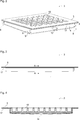
- Figure 2 – is a schematic perspective view of the tray assembly of the cultivator of Fig. 1;
- Figure 3 – is a schematic side view of the upper pull-out tray and the intermediate pull-out tray of the tray assembly of Fig. 1, after having been removed from the cabinet by the user;
- Figure 4 – is a schematic sectional view of the upper pull-out tray and the intermediate pull-out tray of Fig. 3, taken along the line A-A;
- Figure 5 – is a schematic partial perspective view of the cabinet of the cultivator of Fig. 1, wherein the tray assembly of Fig. 2 has been omitted;
- Figure 6 – is a schematic partial side view of the guiding means the shift mechanism of the cultivator of Fig.1;
- Figure 7 – is a schematic partial side view of the shift mechanism and the tray assembly of the cultivator of Fig.1, wherein the lower tray is in the locking position;
- Figure 8 – is a schematic partial side view of the shift mechanism and the tray assembly of the cultivator of Fig.1, wherein the lower tray is being moved from the locking position to the unlocking position;
- Figure 9 – is a schematic partial side view of the shift mechanism and the tray assembly of the cultivator of Fig.1, wherein the lower tray is in the unlocking position;
- Figure 10 – is a schematic perspective view of the upper pull-out tray of the cultivator of Fig.1;
- Figure 11 – is a schematic perspective enlarged view of a receptacle in the upper pull-out tray of Fig. 10;
- Figure 12 – is a schematic perspective view of different upper pull-out trays of the cultivator of Fig.1;
- Figure 13 – is a schematic perspective view of the intermediate upper pull-out tray of the cultivator of Fig.1.
- the cultivator (1) comprises: a cabinet (2) which comprises one or more tray assemblies (3) for growing plants (not shown), wherein the tray assembly (3) comprises: a lower tray (4) for receiving a nutrient solution (not shown) for the plants; and an upper pull-out tray (5) for holding the plants, wherein the upper pull-out tray (5) is partly dipped into the lower tray (4); and a watering means (6) for filling the nutrient solution into the lower tray (4) so as to flood the roots of the plants held in the upper pull-out tray (5) and for draining the nutrient solution away from the lower tray (4) (Fig. 1).
- the cultivator (1) of the present invention further comprises: a shift mechanism (7) for selectively shifting the lower tray (4) to a locking position and an unlocking position (Fig. 7 to Fig. 9).
- a shift mechanism (7) for selectively shifting the lower tray (4) to a locking position and an unlocking position (Fig. 7 to Fig. 9).
- a shift mechanism (7) for selectively shifting the lower tray (4) to a locking position and an unlocking position (Fig. 7 to Fig. 9).
- a shift mechanism (7) for selectively shifting the lower tray (4) to a locking position and an unlocking position (Fig. 7 to Fig. 9).
- the shift mechanism (7) comprises two guiding means (8) which are disposed between the side walls of the cabinet (2) and the side walls of the lower tray (4) respectively (Fig. 2 and Fig. 6).
- each guiding means (8) is adapted to guide the lower tray (4) between locking position and the unlocking position (Fig. 8).
- the guiding means (8) comprises: two pins (9) which are disposed onto the respective side wall of the lower tray (4); and two guides (10) which are disposed onto the respective side wall of the cabinet (2) (Fig. 2 and Fig. 5).
- each guide (10) comprises a slot (11) which slidably engages with the respective pin (9) (Fig. 8).
- the guides (10) which are close to the rear wall of the lower tray (4) have horizontally extending straight slots (11) (Fig. 6 and Fig.7).
- the guides (10) which are close to the front wall of the lower tray (4) have horizontally and downwardly extending L-shaped slots (11).
- the slots (11) are arranged such that the front wall of the lower tray (4) is relatively lowered in the unlocking position (Fig. 1 and Fig. 9).
- the watering means (6) comprises: a tank (12) for storing the nutrient solution; and a port (13) for selectively filling and draining the lower tray (4) (Fig. 1).
- the port (13) is disposed onto the lower tray (4) and flexibly connected through a hose (14) with the tank (12) (Fig. 1 and Fig. 2).
- the bottom surface of the lower tray (4) is sloping in the locking position downwardly towards the port (13) (Fig. 7).
- the port (13) is disposed onto the rear wall of the lower tray (4) (Fig. 1 and Fig. 2).
- the upper pull-out tray (5) comprises one or more receptacles (15) for holding the plants (Fig. 2 and Fig. 4).
- the bottom surface of the receptacle (15) comprises one or more holes (16) which allow the roots of the plants to grow downwards (Fig. 10 and Fig. 11).
- the receptacles (15) are integrally formed with the upper pull-out tray (5) (Fig. 10).
- the receptacles (15) are detachably disposed into the upper pull-out tray (5).
- the receptacles (15) are arranged in arrays (Fig. 10).
- the receptacles (15) are cylindrical shaped (Fig. 11).
- the receptacle (15) may have different sizes (Fig. 12).
- the tray assembly (3) further comprises: an intermediate pull-out tray (17) for spreading the nutrient solution underside of the upper pull-out tray (5) (Fig. 4).
- the base of the intermediate pull-out tray (17) is separated from the bottom surface of the upper pull-out tray (5) through a predetermined gap and has at least one opening (18) for allowing passage of the nutrient solution (Fig. 4).
- the upper pull-out tray (5) is partly dipped into the the intermediate pull-out tray (17) (Fig. 4).
- the intermediate pull-out tray (17) is partly dipped into lower tray (4) (Fig. 1 and Fig. 2).
- the base of the intermediate pull-out tray (17) slopes downwardly towards the opening (18) so as to allow drainage of the nutrient solution into the lower tray (4) (Fig. 4).
- the opening (18) of the intermediate pull-out tray (17) is centered (Fig. 13).
- a major advantageous effect of the present invention is that when sowing the seeds or when harvesting the plants, the user is enabled to remove the upper pull-out tray (5) from the cabinet (2) separately from the lower tray (4) by virtue of the shift mechanism (7).
- the need for removing the lower tray (4) when sowing the seeds or when harvesting the plants has been obviated, and thus the wearing out of the aforementioned elastic gasket and the risk of leakage of the nutrient solution can be eliminated or reduced as much as possible.
- the removal and replacement of the upper pull-out tray (5) can be conducted with less effort.
- Other advantageous effects of the present invention can be taken from the above described embodiments.
Landscapes
- Life Sciences & Earth Sciences (AREA)
- Environmental Sciences (AREA)
- Cultivation Receptacles Or Flower-Pots, Or Pots For Seedlings (AREA)
Abstract
The present invention relates to a cultivator (1) comprising: a cabinet (2) which comprises one or more tray assemblies (3) for growing plants, wherein the tray assembly (3) comprises: a lower tray (4) for receiving a nutrient solution for the plants; and an upper pull-out tray (5) for holding the plants, wherein the upper pull-out tray (5) is partly dipped into the lower tray (4); and a watering means (6) for filling the nutrient solution into the lower tray (4) so as to flood the roots of the plants held in the upper pull-out tray (5) and for draining the nutrient solution away from the lower tray (4).
Description
The present invention relates to a cultivator for growing plants, in particular to a domestic cultivator.
Cultivators for domestic use are commonly known in the art. A cultivator generally comprises: a cabinet which comprises one or more tray assemblies for growing plants, wherein the tray assembly comprises: a lower pull-out tray for receiving a nutrient solution for the plants; and an upper pull-out tray for holding the plants, wherein the upper pull-out tray is partly dipped into the lower pull-out tray; and a watering means for filling the nutrient solution into the lower pull-out tray so as to flood the roots of the plants held in the upper pull-out tray and for draining the nutrient solution away from the lower pull-out tray. The lower pull-out tray generally comprises a quick-joint type inlet and a quick joint type drain. When sowing the seeds, the user opens the cabinet door, removes the lower pull-out tray and the upper pull-out tray from the cabinet, puts the seeds into the upper pull-out tray, and subsequently replaces the lower pull-out tray and the upper pull-out tray into the cabinet. Similarly when harvesting the plants the user opens the cabinet door, removes the lower pull-out tray and the upper pull-out tray, harvests a desired amount of the plants, and subsequently replaces the lower pull-out tray and the upper pull-out tray into the cabinet.
USD659724S discloses a herb cultivator for domestic use.
A problem with the prior art cultivator is that the elastic gaskets in the quick-joint type inlet/drain wear out on frequent removal/replacement of the lower pull-out tray and the upper pull-out tray. In such instances, the sealing performance of the elastic gaskets decrease, and the nutrient solution leaks into the cabinet, and wets the floor, and thus causes damages and poses a risk to safety of the user. In such instances, the elastic gaskets must be replaced by the service personnel.
An objective of the present invention is to provide a cultivator which solves the problems of the prior art in a cost-effective way and which enables an improved usability and safety.
This objective has been achieved by the cultivator as defined in claim 1. Further achievements have been attained by the subject-matters respectively defined in the dependent claims.
The cultivator of the present invention comprises a shift mechanism for selectively shifting the lower tray to a locking position and an unlocking position, wherein in the locking position the forward movement of the upper pull-out tray is blocked by the lower tray, wherein in the unlocking position the upper pull-out tray is released from the lower tray and can be moved out of the cabinet.
A major advantageous effect of the present invention is that when sowing the seeds or when harvesting the plants, the user is enabled to remove the upper pull-out tray from the cabinet separately from the lower tray by virtue of the shift mechanism. Thereby, the need for removing the lower tray when sowing the seeds or when harvesting the plants has been obviated, and thus the wearing out of the aforementioned elastic gasket and the risk of leakage of the nutrient solution can be eliminated or reduced as much as possible. Thereby, the removal and replacement of the upper pull-out tray can be conducted with less effort.
In an embodiment, the lower tray can be selectively shifted to the locking position and the unlocking position through one or more guiding means of the shift mechanism. This embodiment is particularly advantageous as the lower tray can be easily and safely shifted by the user.
In another embodiment, the guiding means comprises one or more pins and one or more guides having slots that receive the pins respectively. This embodiment is particularly advantageous as the guides and the pins are cost-effective and reliable.
In another embodiment, the slots which are close to the rear of the cabinet have horizontally extending straight shapes. And the slots which are close to the front of the cabinet have horizontally and downwardly extending L-shapes so as to allow tilting of the lower tray down to a predetermined angle. This embodiment is particularly advantageous as the front wall of the lower tray can be easily lowered in the unlocking position.
In another embodiment, the nutrient solution is selectively filled and drained through a port formed into the lower tray which is flexibly connected to the nutrient solution tank through a hose. This embodiment is particularly advantageous as the lower tray can be easily and safely shifted by virtue of the flexible connection.
In another embodiment, the lower tray has a sloping bottom surface. This embodiment is particularly advantageous as the nutrient solution can be completely and quickly drained. Thereby, the residues of the nutrient solution in the lower tray can be prevented, and thus the lower tray can be kept clean, and the humidity in the cabinet can be easily and properly adjusted.
In another embodiment, the port is formed into the rear wall of the lower tray. Alternatively, the port can be provided separately from the lower tray. These embodiments are particularly advantageous as the port can be concealed from the user.
In another embodiment, the plants can be held through one or more receptacles of the upper pull-out tray. The receptacles have one or more holes which allow the roots of the plants to grow downwards after the germination. This embodiment is particularly advantageous as the various different plants can be separately grown from one another, and thus the sowing and harvesting thereof can be facilitated.
In another embodiment, the receptacles are integrally formed with the upper pull-out tray.
This embodiment is particularly advantageous as the upper pull-out tray becomes easy to handle.
In an alternative embodiment, the receptacles are detachable. This embodiment is particularly advantageous as the receptacles can be separately transported or rearranged. Thereby, the upper pull-out tray can be more flexibly used.
In another embodiment, the receptacles are cylindrical shaped. The receptacles may have different sizes which suit the various plants. This embodiment is particularly advantageous as the upper pull-out tray can be personalized to meet the exact requirements of the user.
In another embodiment, the tray assembly comprises an intermediate pull-out tray for spreading the nutrient solution underside of the upper pull-out tray. In this embodiment, the upper pull-out tray, the intermediate pull-out tray, and the lower tray are nested, and also fluidly communicated through one or more openings in the intermediate pull-out tray. And in the unlocking position the intermediate pull-out tray is released from the lower tray and can be moved out of the cabinet together with the upper pull-out tray. This embodiment is particularly advantageous as the intermediate pull-out tray improves the watering of the plants.
In another embodiment, the base of the intermediate pull-out tray is separated from the bottom surface of the upper pull-out tray through a predetermined gap. This embodiment is particularly advantageous as the roots of the plants can be effectively watered during the flooding.
In another embodiment, the intermediate pull-out tray has a sloping base around its opening. This embodiment is particularly advantageous as the nutrient solution can be completely and quickly drained into the lower tray.
In another embodiment, the opening in the base of the intermediate pull-out tray is centered. This embodiment is particularly advantageous as the plants can be grown substantially uniformly.
Additional features and additional advantageous effects of the cultivator of the present invention will become more apparent with the detailed description of the embodiments with reference to the accompanying drawings in which:
Figure 1 – is a schematic partial sectional view of a cultivator according to an embodiment of the present invention, wherein the tray assembly is in the unlocking position;
Figure 2 – is a schematic perspective view of the tray assembly of the cultivator of Fig. 1;
Figure 3 – is a schematic side view of the upper pull-out tray and the intermediate pull-out tray of the tray assembly of Fig. 1, after having been removed from the cabinet by the user;
Figure 4 – is a schematic sectional view of the upper pull-out tray and the intermediate pull-out tray of Fig. 3, taken along the line A-A;
Figure 5 – is a schematic partial perspective view of the cabinet of the cultivator of Fig. 1, wherein the tray assembly of Fig. 2 has been omitted;
Figure 6 – is a schematic partial side view of the guiding means the shift mechanism of the cultivator of Fig.1;
Figure 7 – is a schematic partial side view of the shift mechanism and the tray assembly of the cultivator of Fig.1, wherein the lower tray is in the locking position;
Figure 8 – is a schematic partial side view of the shift mechanism and the tray assembly of the cultivator of Fig.1, wherein the lower tray is being moved from the locking position to the unlocking position;
Figure 9 – is a schematic partial side view of the shift mechanism and the tray assembly of the cultivator of Fig.1, wherein the lower tray is in the unlocking position;
Figure 10 – is a schematic perspective view of the upper pull-out tray of the cultivator of Fig.1;
Figure 11 – is a schematic perspective enlarged view of a receptacle in the upper pull-out tray of Fig. 10;
Figure 12 – is a schematic perspective view of different upper pull-out trays of the cultivator of Fig.1;
Figure 13 – is a schematic perspective view of the intermediate upper pull-out tray of the cultivator of Fig.1.
The reference signs appearing on the drawings relate to the following technical features.
- Cultivator
- Cabinet
- Tray assembly
- Lower tray
- Upper pull-out tray
- Watering means
- Shift mechanism
- Guiding means
- Pin
- Guide
- Slot
- Tank
- Port
- Hose
- Receptacle
- Hole
- Intermediate pull-out tray
- Opening
The cultivator (1) comprises: a cabinet (2) which comprises one or more tray assemblies (3) for growing plants (not shown), wherein the tray assembly (3) comprises: a lower tray (4) for receiving a nutrient solution (not shown) for the plants; and an upper pull-out tray (5) for holding the plants, wherein the upper pull-out tray (5) is partly dipped into the lower tray (4); and a watering means (6) for filling the nutrient solution into the lower tray (4) so as to flood the roots of the plants held in the upper pull-out tray (5) and for draining the nutrient solution away from the lower tray (4) (Fig. 1).
The cultivator (1) of the present invention further comprises: a shift mechanism (7) for selectively shifting the lower tray (4) to a locking position and an unlocking position (Fig. 7 to Fig. 9). In the locking position the forward movement of the upper pull-out tray (5) is blocked by the lower tray (4) (Fig. 7). In the unlocking position the upper pull-out tray (5) is released from the lower tray (4) and can be moved forwardly out of the cabinet (2) (Fig. 1 and Fig. 9).
In an embodiment, the shift mechanism (7) comprises two guiding means (8) which are disposed between the side walls of the cabinet (2) and the side walls of the lower tray (4) respectively (Fig. 2 and Fig. 6). In this embodiment, each guiding means (8) is adapted to guide the lower tray (4) between locking position and the unlocking position (Fig. 8).
In another embodiment, the guiding means (8) comprises: two pins (9) which are disposed onto the respective side wall of the lower tray (4); and two guides (10) which are disposed onto the respective side wall of the cabinet (2) (Fig. 2 and Fig. 5). In this embodiment, each guide (10) comprises a slot (11) which slidably engages with the respective pin (9) (Fig. 8).
In another embodiment, the guides (10) which are close to the rear wall of the lower tray (4) have horizontally extending straight slots (11) (Fig. 6 and Fig.7). In this embodiment, the guides (10) which are close to the front wall of the lower tray (4) have horizontally and downwardly extending L-shaped slots (11). The slots (11) are arranged such that the front wall of the lower tray (4) is relatively lowered in the unlocking position (Fig. 1 and Fig. 9).
In another embodiment, the watering means (6) comprises: a tank (12) for storing the nutrient solution; and a port (13) for selectively filling and draining the lower tray (4) (Fig. 1). In this embodiment, the port (13) is disposed onto the lower tray (4) and flexibly connected through a hose (14) with the tank (12) (Fig. 1 and Fig. 2).
In another embodiment, the bottom surface of the lower tray (4) is sloping in the locking position downwardly towards the port (13) (Fig. 7).
In another embodiment, the port (13) is disposed onto the rear wall of the lower tray (4) (Fig. 1 and Fig. 2).
In another embodiment, the upper pull-out tray (5) comprises one or more receptacles (15) for holding the plants (Fig. 2 and Fig. 4). In this embodiment, the bottom surface of the receptacle (15) comprises one or more holes (16) which allow the roots of the plants to grow downwards (Fig. 10 and Fig. 11).
In another embodiment, the receptacles (15) are integrally formed with the upper pull-out tray (5) (Fig. 10).
In an alternative embodiment, the receptacles (15) are detachably disposed into the upper pull-out tray (5).
In another embodiment, the receptacles (15) are arranged in arrays (Fig. 10).
In another embodiment, the receptacles (15) are cylindrical shaped (Fig. 11). The receptacle (15) may have different sizes (Fig. 12).
In another embodiment, the tray assembly (3) further comprises: an intermediate pull-out tray (17) for spreading the nutrient solution underside of the upper pull-out tray (5) (Fig. 4). In this embodiment, the base of the intermediate pull-out tray (17) is separated from the bottom surface of the upper pull-out tray (5) through a predetermined gap and has at least one opening (18) for allowing passage of the nutrient solution (Fig. 4). In this embodiment, the upper pull-out tray (5) is partly dipped into the the intermediate pull-out tray (17) (Fig. 4). In addition, the intermediate pull-out tray (17) is partly dipped into lower tray (4) (Fig. 1 and Fig. 2). In the locking position the forward movement of the intermediate pull-out tray (17) is blocked by the lower tray (4) (Fig.7). An in the unlocking position the intermediate pull-out tray (17) is released from the lower tray (4) and can be moved out of the cabinet (2) together with the upper pull-out tray (5) (Fig. 9).
In another embodiment, the base of the intermediate pull-out tray (17) slopes downwardly towards the opening (18) so as to allow drainage of the nutrient solution into the lower tray (4) (Fig. 4).
In another embodiment, the opening (18) of the intermediate pull-out tray (17) is centered (Fig. 13).
A major advantageous effect of the present invention is that when sowing the seeds or when harvesting the plants, the user is enabled to remove the upper pull-out tray (5) from the cabinet (2) separately from the lower tray (4) by virtue of the shift mechanism (7). Thereby, the need for removing the lower tray (4) when sowing the seeds or when harvesting the plants has been obviated, and thus the wearing out of the aforementioned elastic gasket and the risk of leakage of the nutrient solution can be eliminated or reduced as much as possible. Thereby, the removal and replacement of the upper pull-out tray (5) can be conducted with less effort. Other advantageous effects of the present invention can be taken from the above described embodiments.
Claims (15)
- A cultivator (1) comprising: a cabinet (2) which comprises one or more tray assemblies (3) for growing plants, wherein the tray assembly (3) comprises: a lower tray (4) for receiving a nutrient solution for the plants; and an upper pull-out tray (5) for holding the plants, wherein the upper pull-out tray (5) is partly dipped into the lower tray (4); and a watering means (6) for filling the nutrient solution into the lower tray (4) so as to flood the roots of the plants held in the upper pull-out tray (5) and for draining the nutrient solution away from the lower tray (4), characterized by further comprising: a shift mechanism (7) for selectively shifting the lower tray (4) to a locking position and an unlocking position, wherein in the locking position the forward movement of the upper pull-out tray (5) is blocked by the lower tray (4), and wherein in the unlocking position the upper pull-out tray (5) is released from the lower tray (4) and can be moved forwardly out of the cabinet (2).
- The cultivator (1) according to claim 1, characterized in that the shift mechanism (7) comprises two guiding means (8) which are disposed between the side walls of the cabinet (2) and the side walls of the lower tray (4) respectively, wherein each guiding means (8) is adapted to guide the lower tray (4) between locking position and the unlocking position.
- The cultivator (1) according to claim 2, characterized in that the guiding means (8) comprises: two pins (9) which are disposed onto the respective side wall of the lower tray (4); and two guides (10) which are disposed onto the respective side wall of the cabinet (2), wherein each guide (10) comprises a slot (11) which slidably engages with the respective pin (9).
- The cultivator (1) according to claim 3, characterized in that the guides (10) which are close to the rear wall of the lower tray (4) have horizontally extending straight slots (11), and the guides (10) which are close to the front wall of the lower tray (4) have horizontally and downwardly extending L-shaped slots (11) which arranged such that the front wall of the lower tray (4) is lowered in the unlocking position.
- The cultivator (1) according to any one of claims 1 to 4, characterized in that the watering means (6) comprises: a tank (12) for storing the nutrient solution; and a port (13) for selectively filling and draining the lower tray (4), wherein the port (13) is disposed onto the lower tray (4) and flexibly connected through a hose (14) with the tank (12).
- The cultivator (1) according to claim 5, characterized in that the bottom surface of the lower tray (4) is sloping in the locking position downwardly towards the port (13) .
- The cultivator (1) according to claim 5 or 6, characterized in that the port (13) is disposed onto the rear wall of the lower tray (4).
- The cultivator (1) according to any one of claims 1 to 7, characterized in that the upper pull-out tray (5) comprises one or more receptacles (15) for holding the plants, wherein the bottom surface of the receptacle (15) comprises one or more holes (16) which allow the roots of the plants to grow through.
- The cultivator (1) according to claim 8, characterized in that the receptacles (15) are integrally formed with the upper pull-out tray (5).
- The cultivator (1) according to claim 8, characterized in that the receptacles (15) are detachably disposed into the upper pull-out tray (5).
- The cultivator (1) according to any one of claims 8 to 10, characterized in that the receptacles (15) are arranged in arrays.
- The cultivator (1) according to any one of claims 8 to 11, characterized in that the receptacles (15) are cylindrical shaped.
- The cultivator (1) according to any one of claims 1 to 12, characterized in that the tray assembly (3) further comprises: an intermediate pull-out tray (17) for spreading the nutrient solution on the underside of the upper pull-out tray (5), wherein the base of the intermediate pull-out tray (17) is separated from the bottom surface of the upper pull-out tray (5) through a predetermined gap and has at least one opening (18) for allowing passage of the nutrient solution, wherein the upper pull-out tray (5) is partly dipped into the intermediate pull-out tray (17), wherein the intermediate pull-out tray (17) is partly dipped into lower tray (4), and wherein in the locking position the forward movement of the intermediate pull-out tray (17) is blocked by the lower tray (4), and wherein in the unlocking position the intermediate pull-out tray (17) is released from the lower tray (4) and can be moved forwardly out of the cabinet (2) together with the upper pull-out tray (5).
- The cultivator (1) according to claim 13, characterized in that the base of the intermediate pull-out tray (17) slopes downwardly towards the opening (18) so as to allow complete drainage of the nutrient solution into the lower tray (4).
- The cultivator (1) according to claim 13 or 14, characterized in that the opening (18) of the intermediate pull-out tray (17) is centered.
Priority Applications (1)
| Application Number | Priority Date | Filing Date | Title |
|---|---|---|---|
| PCT/EP2016/065464 WO2018001503A1 (en) | 2016-07-01 | 2016-07-01 | Cultivator with improved usability and safety |
Applications Claiming Priority (1)
| Application Number | Priority Date | Filing Date | Title |
|---|---|---|---|
| PCT/EP2016/065464 WO2018001503A1 (en) | 2016-07-01 | 2016-07-01 | Cultivator with improved usability and safety |
Publications (1)
| Publication Number | Publication Date |
|---|---|
| WO2018001503A1 true WO2018001503A1 (en) | 2018-01-04 |
Family
ID=56507568
Family Applications (1)
| Application Number | Title | Priority Date | Filing Date |
|---|---|---|---|
| PCT/EP2016/065464 Ceased WO2018001503A1 (en) | 2016-07-01 | 2016-07-01 | Cultivator with improved usability and safety |
Country Status (1)
| Country | Link |
|---|---|
| WO (1) | WO2018001503A1 (en) |
Citations (7)
| Publication number | Priority date | Publication date | Assignee | Title |
|---|---|---|---|---|
| US1031771A (en) * | 1912-04-22 | 1912-07-09 | William J Buttschau | Seed-testing apparatus. |
| FR48847E (en) * | 1937-01-25 | 1938-07-12 | Apparatus for ensuring the germination of seeds or other plant elements | |
| USD659724S1 (en) * | 2011-01-14 | 2012-05-15 | Urban Cultivator Inc. | Herb cultivator |
| KR20150080974A (en) * | 2014-01-02 | 2015-07-13 | 주식회사파멕스 | Movable box for hydroponics |
| CN204560503U (en) * | 2015-04-30 | 2015-08-19 | 梁健丰 | A kind of Household vegetable planter |
| WO2016019157A1 (en) * | 2014-07-30 | 2016-02-04 | Indoor Farms Of America, Llc | Vertical aeroponic plant growing enclosure with support structure |
| WO2016070894A1 (en) * | 2014-11-03 | 2016-05-12 | Arcelik Anonim Sirketi | Improved shelf assembly and refrigeration appliance having the same |
-
2016
- 2016-07-01 WO PCT/EP2016/065464 patent/WO2018001503A1/en not_active Ceased
Patent Citations (7)
| Publication number | Priority date | Publication date | Assignee | Title |
|---|---|---|---|---|
| US1031771A (en) * | 1912-04-22 | 1912-07-09 | William J Buttschau | Seed-testing apparatus. |
| FR48847E (en) * | 1937-01-25 | 1938-07-12 | Apparatus for ensuring the germination of seeds or other plant elements | |
| USD659724S1 (en) * | 2011-01-14 | 2012-05-15 | Urban Cultivator Inc. | Herb cultivator |
| KR20150080974A (en) * | 2014-01-02 | 2015-07-13 | 주식회사파멕스 | Movable box for hydroponics |
| WO2016019157A1 (en) * | 2014-07-30 | 2016-02-04 | Indoor Farms Of America, Llc | Vertical aeroponic plant growing enclosure with support structure |
| WO2016070894A1 (en) * | 2014-11-03 | 2016-05-12 | Arcelik Anonim Sirketi | Improved shelf assembly and refrigeration appliance having the same |
| CN204560503U (en) * | 2015-04-30 | 2015-08-19 | 梁健丰 | A kind of Household vegetable planter |
Similar Documents
| Publication | Publication Date | Title |
|---|---|---|
| KR101248076B1 (en) | Flowerpot of drawer type for wick flood | |
| JP2020182440A (en) | Culture device for precious plant and extinction feared wild plant | |
| DE3611715A1 (en) | COFFEE MACHINE | |
| US20180139915A1 (en) | Hydroponic tray and hydroponic system | |
| KR20140081651A (en) | A Pot tray for under water supply system | |
| KR102324188B1 (en) | Tray for plant cultivation | |
| KR20080091566A (en) | Seedling transplanter | |
| EP3481173B1 (en) | Plant cultivation container | |
| KR102175323B1 (en) | Apparatus for hydroculture | |
| WO2018001503A1 (en) | Cultivator with improved usability and safety | |
| KR20150112155A (en) | The seedtime and raise seedlings transplant have water supply | |
| KR101519965B1 (en) | Environment-friendly Lid for Toilet bucket capable of growing plant | |
| KR101865289B1 (en) | FlOWERPOT SET FOR TRANSPLANTING FLOWER | |
| JP7011514B2 (en) | Wall greening panel | |
| KR200472498Y1 (en) | Seedlings Transplanter | |
| KR20090020887A (en) | Multi-stage Planter | |
| JP6507371B2 (en) | Plant cultivation equipment | |
| JP6330771B2 (en) | Transplanter | |
| KR970000561Y1 (en) | Flower-pot | |
| KR200369220Y1 (en) | Apparatus of setting grouth butts of the soybean sprout culture cabinet | |
| JP2017063660A5 (en) | ||
| KR200481744Y1 (en) | A flowerpot | |
| KR100718910B1 (en) | Bean sprouts grower | |
| CN217546787U (en) | Combined root rot-proof flowerpot capable of continuously supplying water | |
| KR20200110044A (en) | Plant container |
Legal Events
| Date | Code | Title | Description |
|---|---|---|---|
| 121 | Ep: the epo has been informed by wipo that ep was designated in this application |
Ref document number: 16741545 Country of ref document: EP Kind code of ref document: A1 |
|
| NENP | Non-entry into the national phase |
Ref country code: DE |
|
| 122 | Ep: pct application non-entry in european phase |
Ref document number: 16741545 Country of ref document: EP Kind code of ref document: A1 |