WO2017222072A1 - 姿勢分析装置、姿勢分析方法、及びコンピュータ読み取り可能な記録媒体 - Google Patents
姿勢分析装置、姿勢分析方法、及びコンピュータ読み取り可能な記録媒体 Download PDFInfo
- Publication number
- WO2017222072A1 WO2017222072A1 PCT/JP2017/023310 JP2017023310W WO2017222072A1 WO 2017222072 A1 WO2017222072 A1 WO 2017222072A1 JP 2017023310 W JP2017023310 W JP 2017023310W WO 2017222072 A1 WO2017222072 A1 WO 2017222072A1
- Authority
- WO
- WIPO (PCT)
- Prior art keywords
- subject
- posture
- limbs
- posture analysis
- computer
- Prior art date
- Legal status (The legal status is an assumption and is not a legal conclusion. Google has not performed a legal analysis and makes no representation as to the accuracy of the status listed.)
- Ceased
Links
Images




Classifications
-
- A—HUMAN NECESSITIES
- A61—MEDICAL OR VETERINARY SCIENCE; HYGIENE
- A61B—DIAGNOSIS; SURGERY; IDENTIFICATION
- A61B5/00—Measuring for diagnostic purposes; Identification of persons
- A61B5/45—For evaluating or diagnosing the musculoskeletal system or teeth
- A61B5/4538—Evaluating a particular part of the muscoloskeletal system or a particular medical condition
- A61B5/4561—Evaluating static posture, e.g. undesirable back curvature
-
- A—HUMAN NECESSITIES
- A61—MEDICAL OR VETERINARY SCIENCE; HYGIENE
- A61B—DIAGNOSIS; SURGERY; IDENTIFICATION
- A61B5/00—Measuring for diagnostic purposes; Identification of persons
- A61B5/103—Measuring devices for testing the shape, pattern, colour, size or movement of the body or parts thereof, for diagnostic purposes
- A61B5/11—Measuring movement of the entire body or parts thereof, e.g. head or hand tremor or mobility of a limb
- A61B5/1113—Local tracking of patients, e.g. in a hospital or private home
- A61B5/1114—Tracking parts of the body
-
- A—HUMAN NECESSITIES
- A61—MEDICAL OR VETERINARY SCIENCE; HYGIENE
- A61B—DIAGNOSIS; SURGERY; IDENTIFICATION
- A61B5/00—Measuring for diagnostic purposes; Identification of persons
- A61B5/103—Measuring devices for testing the shape, pattern, colour, size or movement of the body or parts thereof, for diagnostic purposes
- A61B5/11—Measuring movement of the entire body or parts thereof, e.g. head or hand tremor or mobility of a limb
- A61B5/1116—Determining posture transitions
-
- A—HUMAN NECESSITIES
- A61—MEDICAL OR VETERINARY SCIENCE; HYGIENE
- A61B—DIAGNOSIS; SURGERY; IDENTIFICATION
- A61B5/00—Measuring for diagnostic purposes; Identification of persons
- A61B5/103—Measuring devices for testing the shape, pattern, colour, size or movement of the body or parts thereof, for diagnostic purposes
- A61B5/11—Measuring movement of the entire body or parts thereof, e.g. head or hand tremor or mobility of a limb
- A61B5/1126—Measuring movement of the entire body or parts thereof, e.g. head or hand tremor or mobility of a limb using a particular sensing technique
- A61B5/1128—Measuring movement of the entire body or parts thereof, e.g. head or hand tremor or mobility of a limb using a particular sensing technique using image analysis
-
- A—HUMAN NECESSITIES
- A61—MEDICAL OR VETERINARY SCIENCE; HYGIENE
- A61B—DIAGNOSIS; SURGERY; IDENTIFICATION
- A61B5/00—Measuring for diagnostic purposes; Identification of persons
- A61B5/72—Signal processing specially adapted for physiological signals or for diagnostic purposes
- A61B5/7271—Specific aspects of physiological measurement analysis
- A61B5/7275—Determining trends in physiological measurement data; Predicting development of a medical condition based on physiological measurements, e.g. determining a risk factor
-
- G—PHYSICS
- G06—COMPUTING OR CALCULATING; COUNTING
- G06T—IMAGE DATA PROCESSING OR GENERATION, IN GENERAL
- G06T7/00—Image analysis
-
- G—PHYSICS
- G06—COMPUTING OR CALCULATING; COUNTING
- G06T—IMAGE DATA PROCESSING OR GENERATION, IN GENERAL
- G06T7/00—Image analysis
- G06T7/0002—Inspection of images, e.g. flaw detection
- G06T7/0012—Biomedical image inspection
-
- G—PHYSICS
- G06—COMPUTING OR CALCULATING; COUNTING
- G06T—IMAGE DATA PROCESSING OR GENERATION, IN GENERAL
- G06T7/00—Image analysis
- G06T7/50—Depth or shape recovery
- G06T7/521—Depth or shape recovery from laser ranging, e.g. using interferometry; from the projection of structured light
-
- G—PHYSICS
- G06—COMPUTING OR CALCULATING; COUNTING
- G06T—IMAGE DATA PROCESSING OR GENERATION, IN GENERAL
- G06T7/00—Image analysis
- G06T7/70—Determining position or orientation of objects or cameras
- G06T7/73—Determining position or orientation of objects or cameras using feature-based methods
- G06T7/75—Determining position or orientation of objects or cameras using feature-based methods involving models
-
- G—PHYSICS
- G06—COMPUTING OR CALCULATING; COUNTING
- G06V—IMAGE OR VIDEO RECOGNITION OR UNDERSTANDING
- G06V40/00—Recognition of biometric, human-related or animal-related patterns in image or video data
- G06V40/10—Human or animal bodies, e.g. vehicle occupants or pedestrians; Body parts, e.g. hands
- G06V40/103—Static body considered as a whole, e.g. static pedestrian or occupant recognition
-
- G—PHYSICS
- G16—INFORMATION AND COMMUNICATION TECHNOLOGY [ICT] SPECIALLY ADAPTED FOR SPECIFIC APPLICATION FIELDS
- G16H—HEALTHCARE INFORMATICS, i.e. INFORMATION AND COMMUNICATION TECHNOLOGY [ICT] SPECIALLY ADAPTED FOR THE HANDLING OR PROCESSING OF MEDICAL OR HEALTHCARE DATA
- G16H30/00—ICT specially adapted for the handling or processing of medical images
- G16H30/40—ICT specially adapted for the handling or processing of medical images for processing medical images, e.g. editing
-
- G—PHYSICS
- G16—INFORMATION AND COMMUNICATION TECHNOLOGY [ICT] SPECIALLY ADAPTED FOR SPECIFIC APPLICATION FIELDS
- G16H—HEALTHCARE INFORMATICS, i.e. INFORMATION AND COMMUNICATION TECHNOLOGY [ICT] SPECIALLY ADAPTED FOR THE HANDLING OR PROCESSING OF MEDICAL OR HEALTHCARE DATA
- G16H40/00—ICT specially adapted for the management or administration of healthcare resources or facilities; ICT specially adapted for the management or operation of medical equipment or devices
- G16H40/60—ICT specially adapted for the management or administration of healthcare resources or facilities; ICT specially adapted for the management or operation of medical equipment or devices for the operation of medical equipment or devices
- G16H40/63—ICT specially adapted for the management or administration of healthcare resources or facilities; ICT specially adapted for the management or operation of medical equipment or devices for the operation of medical equipment or devices for local operation
-
- A—HUMAN NECESSITIES
- A61—MEDICAL OR VETERINARY SCIENCE; HYGIENE
- A61B—DIAGNOSIS; SURGERY; IDENTIFICATION
- A61B5/00—Measuring for diagnostic purposes; Identification of persons
- A61B5/68—Arrangements of detecting, measuring or recording means, e.g. sensors, in relation to patient
- A61B5/6887—Arrangements of detecting, measuring or recording means, e.g. sensors, in relation to patient mounted on external non-worn devices, e.g. non-medical devices
- A61B5/6891—Furniture
-
- G—PHYSICS
- G06—COMPUTING OR CALCULATING; COUNTING
- G06T—IMAGE DATA PROCESSING OR GENERATION, IN GENERAL
- G06T2207/00—Indexing scheme for image analysis or image enhancement
- G06T2207/10—Image acquisition modality
- G06T2207/10028—Range image; Depth image; 3D point clouds
-
- G—PHYSICS
- G06—COMPUTING OR CALCULATING; COUNTING
- G06T—IMAGE DATA PROCESSING OR GENERATION, IN GENERAL
- G06T2207/00—Indexing scheme for image analysis or image enhancement
- G06T2207/30—Subject of image; Context of image processing
- G06T2207/30196—Human being; Person
-
- G—PHYSICS
- G16—INFORMATION AND COMMUNICATION TECHNOLOGY [ICT] SPECIALLY ADAPTED FOR SPECIFIC APPLICATION FIELDS
- G16H—HEALTHCARE INFORMATICS, i.e. INFORMATION AND COMMUNICATION TECHNOLOGY [ICT] SPECIALLY ADAPTED FOR THE HANDLING OR PROCESSING OF MEDICAL OR HEALTHCARE DATA
- G16H50/00—ICT specially adapted for medical diagnosis, medical simulation or medical data mining; ICT specially adapted for detecting, monitoring or modelling epidemics or pandemics
- G16H50/30—ICT specially adapted for medical diagnosis, medical simulation or medical data mining; ICT specially adapted for detecting, monitoring or modelling epidemics or pandemics for calculating health indices; for individual health risk assessment
Definitions
- the present invention relates to a posture analysis apparatus and posture analysis method for analyzing a posture of a person, and further relates to a computer-readable recording medium in which a program for realizing these is recorded.
- OWAS Oleko Working Posture Analyzing System
- FIGS. 8 and 9 are diagram showing an evaluation table used in OWAS.
- the posture code is set for each of the back, the upper limb, the lower limb, and the weight of the object.
- the contents of each posture code shown in FIG. 8 are as follows.
- the analyst checks the movements of the back, upper limbs, and lower limbs of each worker for each movement with the posture code shown in FIG. 8 while observing the work of the worker photographed on video. Then, the analyst specifies corresponding codes for the back, upper limbs, and lower limbs, and records the specified codes. The analyst also records a code corresponding to the weight of the object handled by the operator. Thereafter, the analyst applies the recorded codes to the evaluation table shown in FIG. 9 to determine the risk of health problems in each work.
- An object of the present invention is to provide an attitude analysis apparatus, an attitude analysis method, and a computer-readable recording medium that can solve the above-described problems and can analyze the attitude of a target person without human intervention. .
- a posture analysis device is a device for analyzing a posture of a subject, A data acquisition unit for acquiring data that changes in accordance with the movement of the subject; A skeletal information creation unit that creates skeletal information that identifies positions of a plurality of parts of the subject based on the data; Based on the skeletal information, a state specifying unit that specifies the respective states of the back, upper limbs, and lower limbs of the subject, A posture analysis unit that analyzes the posture of the subject based on the identified states of the back, upper limbs, and lower limbs of the subject; It is characterized by having.
- a posture analysis method is a method for analyzing a posture of a target person, (A) obtaining data that changes according to the action of the subject; (B) based on the data, creating skeletal information that identifies the positions of the plurality of parts of the subject; (C) based on the skeletal information, identifying the respective states of the back, upper limbs, and lower limbs of the subject; (D) analyzing the posture of the subject based on the identified states of the back, upper limbs, and lower limbs of the subject; It is characterized by having.
- a computer-readable recording medium is a computer-readable recording medium in which a program for analyzing the posture of a subject is recorded by a computer, In the computer, (A) obtaining data that changes according to the action of the subject; (B) based on the data, creating skeletal information that identifies the positions of the plurality of parts of the subject; (C) based on the skeletal information, identifying the respective states of the back, upper limbs, and lower limbs of the subject; (D) analyzing the posture of the subject based on the identified states of the back, upper limbs, and lower limbs of the subject; A program including an instruction for executing is recorded.
- FIG. 1 is a block diagram showing a schematic configuration of the posture analysis apparatus according to the embodiment of the present invention.
- FIG. 2 is a block diagram showing a specific configuration of the posture analysis apparatus in the present embodiment.
- FIG. 3 is a diagram showing an example of the skeleton information created in the embodiment of the present invention.
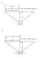
- FIG. 4 is a diagram for explaining the calculation process of the three-dimensional coordinates in the embodiment of the present invention.
- FIG. 4A shows the calculation process in the horizontal direction (X coordinate) of the image, and FIG. The calculation process in the vertical direction (Y coordinate) of an image is shown.
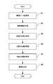
- FIG. 5 is a flowchart showing the operation of the posture analysis apparatus according to the embodiment of the present invention.
- FIG. 6 is a flowchart specifically showing the lower limb code determination process shown in FIG. FIG.
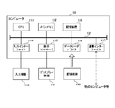
- FIG. 7 is a block diagram illustrating an example of a computer that implements the posture analysis apparatus according to the embodiment of the present invention.
- FIG. 8 is a diagram illustrating an attitude code used in OWAS.
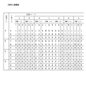
- FIG. 9 is a diagram showing an evaluation table used in OWAS.
- FIG. 1 is a block diagram showing a schematic configuration of the posture analysis apparatus according to the embodiment of the present invention.
- the posture analysis apparatus 10 includes a data acquisition unit 11, a skeleton information creation unit 12, a state identification unit 13, and a posture analysis unit 14.
- the data acquisition unit 11 acquires data that changes according to the operation of the target person.
- the skeletal information creation unit 12 creates skeletal information that identifies the positions of a plurality of parts of the subject based on the acquired data.
- the state specifying unit 13 specifies the respective states of the back, upper limbs, and lower limbs of the subject based on the skeleton information.
- the posture analysis unit 14 analyzes the posture of the subject based on the identified states of the back, upper limbs, and lower limbs of the subject.
- the postures of workers, caregivers, and the like can be specified from data that changes in accordance with the movement of the subject. That is, according to the present embodiment, it is possible to analyze the posture of the subject person without manual intervention.
- FIG. 2 is a block diagram showing a specific configuration of the posture analysis apparatus in the present embodiment.
- the depth sensor 20 includes, for example, a light source that emits infrared laser light in a specific pattern and an image sensor that receives infrared light reflected by an object, and thereby image data to which a depth for each pixel is added. Is output.
- a specific example of the depth sensor is an existing depth sensor such as Kinect (registered trademark).
- the depth sensor 20 is arranged so as to be able to photograph the motion of the subject 40. Therefore, in this Embodiment, the data acquisition part 11 acquires the image data with the depth which the subject person 40 was reflected from the depth sensor 20 as data which changes according to operation
- the skeleton information creation unit 12 calculates, for each image data, the three-dimensional coordinates of a specific part of the user by using the coordinates on the image data and the depth added to the pixels. Skeletal information is created using the three-dimensional coordinates.
- FIG. 3 is a diagram showing an example of the skeleton information created in the embodiment of the present invention.
- the skeleton information is configured by three-dimensional coordinates of each joint for each elapsed time from the start of imaging.
- the X coordinate is the value of the position in the horizontal direction on the image data
- the Y coordinate is the value of the position in the vertical direction on the image data
- the Z coordinate is assigned to the pixel. Depth value.
- Specific parts include, for example, the head, neck, right shoulder, right elbow, right wrist, right hand, right thumb, right hand, left shoulder, left elbow, left wrist, left hand, left thumb, left hand, chest, thoracolumbar region, Examples include the pelvis, right hip joint, right knee, right ankle, right foot, left hip joint, left knee, left ankle, and left foot. In FIG. 3, three-dimensional coordinates of the pelvis, thoracolumbar, and right of the thumb are illustrated.
- FIG. 4 is a diagram for explaining the calculation process of the three-dimensional coordinates in the embodiment of the present invention.
- FIG. 4A shows the calculation process in the horizontal direction (X coordinate) of the image
- FIG. The calculation process in the vertical direction (Y coordinate) of an image is shown.
- the coordinates of a specific point on the image data to which the depth is added are (DX, DY), and the depth at the specific point is DPT.
- the number of pixels in the horizontal direction of the image data is 2CX, and the number of pixels in the vertical direction is 2CY.
- the horizontal viewing angle of the depth sensor is 2 ⁇ , and the vertical viewing angle is 2 ⁇ .
- the three-dimensional coordinates (WX, WY, WZ) of the specific point are calculated by the following equations 1 to 3, as can be seen from FIGS. 4 (a) and 4 (b).
- the state specifying unit 13 specifies the position of each part of the target person 40 from the skeleton information, and the back, upper limb, and lower limb are determined in advance from the specified position of each part. Which pattern is applicable. From the result of this determination, the back, upper limb, and lower limb are identified.
- the state specifying unit 13 uses the three-dimensional coordinates of each part specified from the skeleton information, and the posture of the target person 40 for each of the back, upper limb, and lower limb is shown in FIG. It is determined which of the posture codes is applicable.
- the state specifying unit 13 selects a part (for example, a right foot or a left foot) closest to the ground contact surface from the parts where the positions of the left and right lower limbs are specified, and the position of the selected part ( The position (Y coordinate) of the contact surface of the subject 40 is detected using the Y coordinate). And the state specific
- the state specifying unit 13 compares the position of the ground plane with the positions of the right foot and the left foot of the subject 40, and the lower limb of the subject 40 is one leg center of gravity (lower limb code 3) or one leg center of gravity (lower limb code 5 ) (See FIG. 8). Further, the state specifying unit 13 compares the position of the ground plane with the positions of the right knee and the left knee of the subject 40, and the lower limb of the subject 40 corresponds to knee standing or one knee standing (lower limb code 6). Determine whether or not.
- the posture analysis unit 14 compares the patterns determined for the back, upper limbs, and lower limbs with a risk table that preliminarily defines the relationship between each pattern and the risk. Determine if the posture is at risk.
- the posture analysis unit 14 compares the codes of the back, upper limbs, and lower limbs determined by the state specifying unit 13 with the evaluation table shown in FIG. 9, and specifies the corresponding risk. Then, the posture analysis unit 14 notifies the terminal device 30 of each code determined by the state specifying unit 13 and the specified risk. Thereby, the notified content is displayed on the screen of the terminal device 30.
- FIG. 5 is a flowchart showing the operation of the posture analysis apparatus according to the embodiment of the present invention.
- FIGS. 1 to 4 are referred to as appropriate.
- the posture analysis method is implemented by operating the posture analysis apparatus 10. Therefore, the description of the posture analysis method in the present embodiment is replaced with the following description of the operation of the posture analysis device 10.
- the data acquisition unit 11 acquires the image data with depth output from the depth sensor 20 (step A1).
- the skeletal information creation unit 12 creates skeletal information for specifying the positions of a plurality of parts of the subject person 40 based on the image data acquired in step A1 (step A2).
- the state specifying unit 13 specifies the state of the back of the subject person 40 based on the skeleton information created in step A2 (step A3). Specifically, the state specifying unit 13 acquires the three-dimensional coordinates of the head, neck, chest, thoracolumbar, and pelvis from the skeletal information, and using the acquired three-dimensional coordinates, the back of the subject 40 is It is determined which of the back cords shown in FIG.
- the state specifying unit 13 specifies the state of the upper limb of the target person 40 based on the skeleton information created in Step A2 (Step A4). Specifically, the state specifying unit 13 determines from the skeletal information the tertiary of right shoulder, right elbow, right wrist, right hand, right thumb, right hand, left shoulder, left elbow, left wrist, left hand, left thumb, left hand. The original coordinates are acquired, and using the acquired three-dimensional coordinates, it is determined which of the upper limb codes shown in FIG.
- the state specifying unit 13 specifies the state of the lower limb of the subject 40 based on the skeleton information created in Step A2 (Step A5). Specifically, the state specifying unit 13 acquires the three-dimensional coordinates of the right hip joint, right knee, right ankle, right foot, left hip joint, left knee, left ankle, and left foot from the skeleton information, and uses the acquired three-dimensional coordinates. It is used to determine which of the lower limb codes shown in FIG. Step A5 will be described more specifically with reference to FIG.
- the posture analysis unit 14 analyzes the posture of the subject 40 based on the state of the back, upper limbs, and lower limbs of the subject 40 (step A6). Specifically, the posture analysis unit 14 collates the codes of the back, upper limbs, and lower limbs determined by the state specifying unit 13 with the evaluation table shown in FIG. 9, and specifies the corresponding risk. Then, the posture analysis unit 14 notifies the terminal device 30 of each code determined by the state specifying unit 13 and the specified risk. It is assumed that the analyst has previously set the weight code.
- Steps A1 to A6 are repeatedly executed every time image data is output from the depth sensor 20.
- FIG. 6 is a flowchart specifically showing the lower limb code determination process shown in FIG.
- the state specifying unit 13 determines whether or not the position of the contact surface of the subject 40 is detected (step B1). If the position of the ground plane is not detected as a result of the determination in step B1, the posture analysis unit 14 detects the position of the ground plane (step B2).
- step B1 the state specifying unit 13 selects and selects a part (for example, the right foot or the left foot) that is closest to the ground contact surface from the parts in which the positions of the left and right feet are specified.
- the Y coordinate of the ground contact surface of the subject 40 is detected using the Y coordinate of the part.
- the state specifying unit 13 uses the plurality of image data output during the set time to use the Y of the ground plane. Coordinates may be detected.
- step B3 After the execution of step B3, the process in the state specifying unit 13 ends.
- the state of the lower limb is specified based on the image data output next.
- the state specifying unit 13 can also periodically execute Step B1.
- the posture analysis unit 14 determines whether or not the knee of the subject person 40 is on the contact surface (step B3).
- step B3 the state specifying unit 13 acquires the Y coordinate of the right knee from the skeletal information, calculates the difference between the acquired Y coordinate of the right knee and the Y coordinate of the contact surface, and calculates it. If the difference is less than or equal to the threshold, it is determined that the right knee is on the ground plane. Similarly, the state specifying unit 13 acquires the Y coordinate of the left knee from the skeleton information, calculates the difference between the acquired Y coordinate of the left knee and the Y coordinate of the ground plane, and the calculated difference is equal to or less than the threshold value. Then, it is determined that the left knee is on the ground surface.
- step B3 if any knee is on the ground contact surface, the state specifying unit 13 determines the state of the lower limb as code 6 (one or both knees are on the ground). (Step B4).
- step B3 determines whether both feet of the subject 40 are floating from the ground contact surface (step B5).
- step B5 the state specifying unit 13 obtains the Y coordinates of the right foot and the left foot from the skeleton information, calculates the difference between each Y coordinate and the Y coordinate of the ground plane, and calculates both If the difference exceeds the threshold, it is determined that both feet are floating from the ground contact surface.
- step B6 determines that there is no corresponding code.
- step B5 determines whether the right foot is floating from the ground surface (step B7). Specifically, in step B7, if the difference between the Y coordinate of the right foot calculated in step B5 and the Y coordinate of the ground plane exceeds the threshold value, the state specifying unit 13 determines that the right foot is floating from the ground plane. judge.
- step B7 determines whether the right foot is floating from the ground contact surface. If the result of the determination in step B7 is that the right foot is floating from the ground contact surface, the state specifying unit 13 further determines whether the left knee is bent (step B8).
- step B8 the state specifying unit 13 acquires the three-dimensional coordinates of the left hip joint, left knee, and left ankle from the skeletal information, and uses the acquired three-dimensional coordinates to determine the left hip joint and The distance between the left knee and the distance between the left knee and the left ankle are calculated. Then, the angle of the left knee is calculated using each three-dimensional coordinate and each distance, and when the calculated angle is equal to or less than a threshold (for example, 150 degrees), the state specifying unit 13 indicates that the left knee is bent. judge.
- a threshold for example, 150 degrees
- step B8 determines that the state of the lower limb is code 5 (the middle waist of one leg center of gravity) (step B9).
- step B10 determines the state of the lower limb as code 3 (one leg center of gravity) (step B10).
- step B7 determines whether the right foot is floating from the ground contact surface. Specifically, in step B11, if the difference between the Y coordinate of the left foot calculated in step B5 and the Y coordinate of the ground plane exceeds the threshold, the state specifying unit 13 determines that the left foot is floating from the ground plane. judge.
- step B11 determines whether the left foot is floating from the ground contact surface. If the result of the determination in step B11 is that the left foot is floating from the ground contact surface, the state specifying unit 13 further determines whether or not the right knee is bent (step B12).
- step B12 the state specifying unit 13 acquires the three-dimensional coordinates of the right hip joint, right knee, and right ankle from the skeleton information, and uses the acquired three-dimensional coordinates to determine the right hip joint and The distance between the right knee and the distance between the right knee and the right ankle are calculated. Then, the angle of the right knee is calculated using each three-dimensional coordinate and each distance, and when the calculated angle is equal to or less than a threshold (for example, 150 degrees), the state specifying unit 13 indicates that the right knee is bent. judge.
- a threshold for example, 150 degrees
- step B12 determines that the state of the lower limb is code 5 (the middle waist of one leg center of gravity) (step B13).
- step B14 determines the state of the lower limb as code 3 (one leg center of gravity) (step B14).
- step B11 determines whether both knees are bent (step B15).
- step B15 the state specifying unit 13 calculates the angle of the right knee as in step B8, and also calculates the angle of the left knee as in step B12. And the state specific
- a threshold value for example, 150 degree
- step B15 determines that the state of the lower limb is code 4 (middle waist) (step B16). On the other hand, if it is determined in step B15 that both knees are not bent, the state specifying unit 13 determines whether the right knee is bent but the left knee is straight (step B17).
- step B17 the state specifying unit 13 determines that, when only the right knee angle is equal to or less than a threshold (for example, 150 degrees) among the right knee and left knee angles calculated in step B15, the state specifying unit 13 No. 13 determines that the right knee is bent but the left knee is straight.
- a threshold for example, 150 degrees
- step B18 determines whether the center of gravity of the subject 40 is on the right foot.
- the state specifying unit 13 acquires three-dimensional coordinates of the pelvis part, the right foot and the left foot from the skeletal information, and uses the acquired three-dimensional coordinates to determine the pelvis part and the right foot. Distance, and the distance between the pelvic part and the left foot. And the state specific
- step B18 If it is determined in step B18 that the center of gravity of the subject 40 is on the right foot, the state specifying unit 13 determines that the state of the lower limb is code 5 (the middle waist of one leg center of gravity) (step B19). On the other hand, as a result of the determination in step B18, if the center of gravity of the subject 40 is not on the right foot, the state specifying unit 13 determines the state of the lower limb as code 3 (one foot center of gravity) (step B20).
- step B17 If the result of the determination in step B17 is that the right knee is bent but the left knee is not straight, the state specifying unit 13 has the left knee bent but the right knee straight. It is determined whether or not (step B21).
- step B21 the state specifying unit 13 determines that, when only the left knee angle is less than or equal to a threshold (for example, 150 degrees) among the right knee and left knee angles calculated in step B15, the state specifying unit 13 No. 13 determines that the left knee is bent but the right knee is straight.
- a threshold for example, 150 degrees
- Step B21 when the left knee is bent but the right knee is straight, the state specifying unit 13 determines whether the center of gravity of the subject 40 is on the left foot.
- the state specifying unit 13 acquires three-dimensional coordinates of the pelvis part, the right foot and the left foot from the skeletal information, and uses the acquired three-dimensional coordinates, Distance, and the distance between the pelvic part and the left foot. And the state specific
- step B22 determines the state of the lower limb as code 5 (the middle waist of one foot center of gravity) (step B23).
- step B24 determines the state of the lower limb as code 3 (one foot center of gravity) (step B24).
- step B21 when the left knee is bent but the right knee is not in a straight state, the state specifying unit 13 determines that the leg of the subject 40 is straight. (Step B25).
- the state of the lower limb is specified by the lower limb code shown in FIG.
- the codes 1 and 7 are not determined.
- a pressure sensor is arranged on a chair or the like so that sensor data from the pressure sensor is input to the posture analysis apparatus 10. This makes it possible to make a determination.
- the code 7 can be determined, for example, by calculating the moving speed of the pelvis.
- the code corresponding to the operation of the target person 40 is specified only by having the target person 40 perform work in front of the depth sensor 20, and the target person can be identified without being manually handled.
- the risk of health impairment at 40 can be determined.
- the depth sensor 20 is used to acquire data that changes in accordance with the motion of the subject 40.
- the means for acquiring data is limited to the depth sensor 20.
- a motion capture system may be used instead of the depth sensor 20.
- the motion capture system may be any of an optical type, an inertial sensor type, a mechanical type, a magnetic type, and a video type.
- the program in the present embodiment may be a program that causes a computer to execute steps A1 to A6 shown in FIG.
- a CPU Central Processing Unit
- the posture analysis apparatus 10 and the posture analysis method according to the present embodiment can be realized.
- a CPU Central Processing Unit
- the data acquisition unit 11 the skeleton information creation unit 12, the state identification unit 13, and the posture analysis unit 14, and performs processing.
- each computer may function as any of the data acquisition unit 11, the skeleton information creation unit 12, the state identification unit 13, and the posture analysis unit 14, respectively.
- FIG. 7 is a block diagram illustrating an example of a computer that implements the posture analysis apparatus according to the embodiment of the present invention.
- the computer 110 includes a CPU 111, a main memory 112, a storage device 113, an input interface 114, a display controller 115, a data reader / writer 116, and a communication interface 117. These units are connected to each other via a bus 121 so that data communication is possible.
- the CPU 111 performs various operations by developing the program (code) in the present embodiment stored in the storage device 113 in the main memory 112 and executing them in a predetermined order.
- the main memory 112 is typically a volatile storage device such as a DRAM (Dynamic Random Access Memory).
- the program in the present embodiment is provided in a state of being stored in a computer-readable recording medium 120. Note that the program in the present embodiment may be distributed on the Internet connected via the communication interface 117.
- the storage device 113 includes a hard disk drive and a semiconductor storage device such as a flash memory.
- the input interface 114 mediates data transmission between the CPU 111 and an input device 118 such as a keyboard and a mouse.
- the display controller 115 is connected to the display device 119 and controls display on the display device 119.
- the data reader / writer 116 mediates data transmission between the CPU 111 and the recording medium 120, and reads a program from the recording medium 120 and writes a processing result in the computer 110 to the recording medium 120.
- the communication interface 117 mediates data transmission between the CPU 111 and another computer.
- the recording medium 120 include general-purpose semiconductor storage devices such as CF (Compact Flash (registered trademark)) and SD (Secure Digital), magnetic storage media such as a flexible disk, or CD- Optical storage media such as ROM (Compact Disk Read Only Memory) are listed.
- CF Compact Flash
- SD Secure Digital
- magnetic storage media such as a flexible disk
- CD- Optical storage media such as ROM (Compact Disk Read Only Memory) are listed.
- the posture analysis apparatus 10 can be realized not by using a computer in which a program is installed but also by using hardware corresponding to each unit. Further, part of the posture analysis apparatus 10 may be realized by a program, and the remaining part may be realized by hardware.
- a device for analyzing the posture of a subject A data acquisition unit for acquiring data that changes in accordance with the movement of the subject; A skeletal information creation unit that creates skeletal information that identifies positions of a plurality of parts of the subject based on the data; Based on the skeletal information, a state specifying unit that specifies the respective states of the back, upper limbs, and lower limbs of the subject, A posture analysis unit that analyzes the posture of the subject based on the identified states of the back, upper limbs, and lower limbs of the subject; A posture analysis apparatus comprising:
- the data acquisition unit acquires image data to which a depth for each pixel is added as the data from a depth sensor arranged to photograph the subject.
- the posture analyzer according to appendix 1.
- the state specifying unit specifies the position of each part of the subject from the skeleton information, and the back part, the upper limb, and the lower limb correspond to any of predetermined patterns from the position of each specified part. And determine each state based on the determination result.
- the posture analyzer according to appendix 1 or 2.
- the state specifying unit selects a part that is closest to the ground from the parts whose positions are specified in the lower limbs, and uses the position of the selected part to detect the position of the contact surface of the subject And determining a pattern for the lower limb on the basis of the detected position of the ground plane.
- the posture analyzer according to appendix 3 or 4.
- (Appendix 6) A method for analyzing the posture of a subject, (A) obtaining data that changes according to the action of the subject; (B) based on the data, creating skeletal information that identifies the positions of the plurality of parts of the subject; (C) based on the skeletal information, identifying the respective states of the back, upper limbs, and lower limbs of the subject; (D) analyzing the posture of the subject based on the identified states of the back, upper limbs, and lower limbs of the subject;
- a posture analysis method characterized by comprising:
- step (a) image data to which a depth for each pixel is added is acquired as the data from a depth sensor arranged to photograph the subject.
- step (d) by comparing the pattern determined for each of the back, upper limbs, and lower limbs with a risk table that predefines the relationship between each pattern and the risk, there is a risk in the posture of the subject. Determine if there is, The posture analysis method according to attachment 8.
- step (c) a part closest to the ground is selected from the parts whose positions are specified in the lower limbs, and the position of the contact surface of the subject is selected using the position of the selected part. And determining a pattern for the lower limbs based on the detected position of the ground plane.
- a computer-readable recording medium that records a program for analyzing the posture of a subject by a computer, In the computer, (A) obtaining data that changes according to the action of the subject; (B) based on the data, creating skeletal information that identifies the positions of the plurality of parts of the subject; (C) based on the skeletal information, identifying the respective states of the back, upper limbs, and lower limbs of the subject; (D) analyzing the posture of the subject based on the identified states of the back, upper limbs, and lower limbs of the subject; The computer-readable recording medium which has recorded the program containing the instruction
- step (a) image data to which a depth for each pixel is added is acquired as the data from a depth sensor arranged to photograph the subject.
- step (c) the position of each part of the subject is specified from the skeletal information, and the back part, the upper limb, and the lower limb are each in a predetermined pattern from the position of each specified part.
- step (d) by comparing the pattern determined for each of the back, upper limbs, and lower limbs with a risk table that predefines the relationship between each pattern and the risk, there is a risk in the posture of the subject. Determine if there is, The computer-readable recording medium according to attachment 13.
- step (c) a part closest to the ground is selected from the parts whose positions are specified in the lower limbs, and the position of the contact surface of the subject is selected using the position of the selected part. And determining a pattern for the lower limbs based on the detected position of the ground plane.
- the computer-readable recording medium according to appendix 13 or 14.
- the present invention it is possible to analyze the posture of the target person without manual operation.
- the present invention is useful in production sites, construction sites, medical sites, nursing care sites, and the like.
Landscapes
- Health & Medical Sciences (AREA)
- Engineering & Computer Science (AREA)
- Life Sciences & Earth Sciences (AREA)
- Physics & Mathematics (AREA)
- General Health & Medical Sciences (AREA)
- Medical Informatics (AREA)
- Public Health (AREA)
- Biomedical Technology (AREA)
- Surgery (AREA)
- Molecular Biology (AREA)
- Heart & Thoracic Surgery (AREA)
- Pathology (AREA)
- Biophysics (AREA)
- Animal Behavior & Ethology (AREA)
- Veterinary Medicine (AREA)
- Dentistry (AREA)
- Oral & Maxillofacial Surgery (AREA)
- Physiology (AREA)
- Computer Vision & Pattern Recognition (AREA)
- General Physics & Mathematics (AREA)
- Theoretical Computer Science (AREA)
- Physical Education & Sports Medicine (AREA)
- Radiology & Medical Imaging (AREA)
- Nuclear Medicine, Radiotherapy & Molecular Imaging (AREA)
- Orthopedic Medicine & Surgery (AREA)
- Rheumatology (AREA)
- Human Computer Interaction (AREA)
- Epidemiology (AREA)
- Multimedia (AREA)
- Primary Health Care (AREA)
- Optics & Photonics (AREA)
- Quality & Reliability (AREA)
- Business, Economics & Management (AREA)
- General Business, Economics & Management (AREA)
- Artificial Intelligence (AREA)
- Psychiatry (AREA)
- Signal Processing (AREA)
- Measurement Of The Respiration, Hearing Ability, Form, And Blood Characteristics Of Living Organisms (AREA)
- Image Analysis (AREA)
Abstract
姿勢分析装置(10)は、対象者の姿勢を分析するための装置であって、対象者を撮影するように配置されたデプスセンサから、画素毎の深度が付加された画像データを取得する、データ取得部(11)と、画像データに基づいて、対象者の複数の部位の位置を特定する骨格情報を作成する、骨格情報作成部(12)と、骨格情報に基づいて、対象者における、背部、上肢、及び下肢、それぞれの状態を特定する、状態特定部(13)と、特定された、対象者における、背部、上肢、及び下肢の状態に基づいて、対象者の姿勢を分析する、姿勢分析部(14)と、を備えている。
Description
本発明は、人の姿勢を分析するための、姿勢分析装置、及び姿勢分析方法に関し、更には、これらを実現するためのプログラムを記録したコンピュータ読み取り可能な記録媒体に関する。
従来から、生産現場、建設現場等では、作業員が無理な姿勢をとること等により、腰痛等の健康障害が発生することがある。また、同様の健康障害は、介護施設、病院等において介護士等にも発生している。このため、作業員、介護士等の姿勢を分析して、腰痛等の健康障害の発生を抑制することが求められている。
具体的には、姿勢を分析する手法としては、OWAS(Ovako Working Posture Analysing System)が知られている(非特許文献1及び2参照)。ここで、図8及び図9を用いて、OWASについて説明する。図8は、OWASで用いられる姿勢コードを示す図である。図9は、OWASで用いられる評価表を示す図である。
図8に示すように、姿勢コードは、背部、上肢、下肢、及び対象物の重量、それぞれ毎に設定されている。また、図8に示す各姿勢コードの内容は下記の通りである。
[背部]
1:背筋は真っ直ぐ
2:前屈又は後屈
3:捻る又は体側を曲げる
4:捻る動作と前後屈又は体側曲
1:背筋は真っ直ぐ
2:前屈又は後屈
3:捻る又は体側を曲げる
4:捻る動作と前後屈又は体側曲
[上肢]
1:両腕とも肩より下
2:片腕が肩の高さ以上
3:両腕が肩の高さ以上
1:両腕とも肩より下
2:片腕が肩の高さ以上
3:両腕が肩の高さ以上
[下肢]
1:座る
2:直立
3:片足重心(重心足は真っ直ぐ)
4:中腰
5:片足重心の中腰
6:膝立ち又は片膝立ち
7:歩く(移動)
1:座る
2:直立
3:片足重心(重心足は真っ直ぐ)
4:中腰
5:片足重心の中腰
6:膝立ち又は片膝立ち
7:歩く(移動)
[重量]
1:10kg以下
2:10~20kg
3:20kgを超える
1:10kg以下
2:10~20kg
3:20kgを超える
まず、分析者は、ビデオで撮影した作業者の作業の様子を観察しながら、各作業者について、動作毎に、背部、上肢、下肢の動きを、図8に示す姿勢コードに照合する。そして、分析者は、背部、上肢、下肢それぞれについて対応するコードを特定し、特定したコードを記録する。また、分析者は、作業者が扱う対象物の重量に対応するコードも記録する。その後、分析者は、記録した各コードを、図9に示す評価表に当てはめて、各作業における健康障害のリスクを判定する。
図9において、各コード以外の数値は、リスクを表している。具体的なリスクの内容は下記の通りである。
1:この姿勢による筋骨格系負担は問題ない。リスクは極めて低い。
2:この姿勢は筋骨格系に有害である。リスクは低いが近いうちに改善が必要。
3:この姿勢は筋骨格系に有害である。リスクも高く早急に改善すべき。
4:この姿勢は筋骨格系に非常に有害である。リスクは極めて高く、直ちに改善すべき。
1:この姿勢による筋骨格系負担は問題ない。リスクは極めて低い。
2:この姿勢は筋骨格系に有害である。リスクは低いが近いうちに改善が必要。
3:この姿勢は筋骨格系に有害である。リスクも高く早急に改善すべき。
4:この姿勢は筋骨格系に非常に有害である。リスクは極めて高く、直ちに改善すべき。
このように、OWASを用いれば、作業者、介護士等における負担を客観的に評価することができる。この結果、生産、建設、介護及び医療等の各種現場において、作業工程等の見直しが容易となり、健康障害の発生が抑制されることになる。
"「職場における腰痛予防対策指針」の概要と腰痛等防止のためのリスク評価手法の例",[online],愛知労働局,[平成26年6月1日検索],インターネット<URL:http://aichi-roudoukyoku.jsite.mhlw.go.jp/library/aichi-roudoukyoku/jyoho/roudoueisei/youtuubousi.pdf>
"「OWAS: Ovako式作業姿勢分析システム",[online],平成26年6月1日,愛知労働局,[平成26年6月1日検索],インターネット<URL:http://aichi-roudoukyoku.jsite.mhlw.go.jp/library/aichi-roudoukyoku/jyoho/roudoueisei/youtuubousi.pdf>
ところで、上述したようにOWASは、通常、人手によるビデオ分析にて行なわれている。このため、OWASの実行には、時間及び労力がかかり過ぎるという問題がある。また、OWASの実行を支援するコンピュータソフトウェアは開発されているが、このソフトウェアを利用しても、作業の様子からコードを特定する作業は人手による必要があり、時間及び労力の軽減には限界がある。
本発明の目的の一例は、上記問題を解消し、人手によることなく、対象者の姿勢の分析を行ない得る、姿勢分析装置、姿勢分析方法、及びコンピュータ読み取り可能な記録媒体を提供することにある。
上記目的を達成するため、本発明の一側面における姿勢分析装置は、対象者の姿勢を分析するための装置であって、
前記対象者の動作に応じて変化するデータを取得する、データ取得部と、
前記データに基づいて、前記対象者の複数の部位の位置を特定する骨格情報を作成する、骨格情報作成部と、
前記骨格情報に基づいて、前記対象者における、背部、上肢、及び下肢、それぞれの状態を特定する、状態特定部と、
特定された、前記対象者における、背部、上肢、及び下肢の状態に基づいて、前記対象者の姿勢を分析する、姿勢分析部と、
を備えていることを特徴とする。
前記対象者の動作に応じて変化するデータを取得する、データ取得部と、
前記データに基づいて、前記対象者の複数の部位の位置を特定する骨格情報を作成する、骨格情報作成部と、
前記骨格情報に基づいて、前記対象者における、背部、上肢、及び下肢、それぞれの状態を特定する、状態特定部と、
特定された、前記対象者における、背部、上肢、及び下肢の状態に基づいて、前記対象者の姿勢を分析する、姿勢分析部と、
を備えていることを特徴とする。
また、上記目的を達成するため、本発明の一側面における姿勢分析方法は、対象者の姿勢を分析するための方法であって、
(a)前記対象者の動作に応じて変化するデータを取得する、ステップと、
(b)前記データに基づいて、前記対象者の複数の部位の位置を特定する骨格情報を作成する、ステップと、
(c)前記骨格情報に基づいて、前記対象者における、背部、上肢、及び下肢、それぞれの状態を特定する、ステップと、
(d)特定された、前記対象者における、背部、上肢、及び下肢の状態に基づいて、前記対象者の姿勢を分析する、ステップと、
を有することを特徴とする。
(a)前記対象者の動作に応じて変化するデータを取得する、ステップと、
(b)前記データに基づいて、前記対象者の複数の部位の位置を特定する骨格情報を作成する、ステップと、
(c)前記骨格情報に基づいて、前記対象者における、背部、上肢、及び下肢、それぞれの状態を特定する、ステップと、
(d)特定された、前記対象者における、背部、上肢、及び下肢の状態に基づいて、前記対象者の姿勢を分析する、ステップと、
を有することを特徴とする。
更に、上記目的を達成するため、本発明の一側面におけるコンピュータ読み取り可能な記録媒体は、コンピュータによって、対象者の姿勢を分析するためのプログラムを記録したコンピュータ読み取り可能な記録媒体であって、
前記コンピュータに、
(a)前記対象者の動作に応じて変化するデータを取得する、ステップと、
(b)前記データに基づいて、前記対象者の複数の部位の位置を特定する骨格情報を作成する、ステップと、
(c)前記骨格情報に基づいて、前記対象者における、背部、上肢、及び下肢、それぞれの状態を特定する、ステップと、
(d)特定された、前記対象者における、背部、上肢、及び下肢の状態に基づいて、前記対象者の姿勢を分析する、ステップと、
を実行させる、命令を含むプログラムを記録していることを特徴とする。
前記コンピュータに、
(a)前記対象者の動作に応じて変化するデータを取得する、ステップと、
(b)前記データに基づいて、前記対象者の複数の部位の位置を特定する骨格情報を作成する、ステップと、
(c)前記骨格情報に基づいて、前記対象者における、背部、上肢、及び下肢、それぞれの状態を特定する、ステップと、
(d)特定された、前記対象者における、背部、上肢、及び下肢の状態に基づいて、前記対象者の姿勢を分析する、ステップと、
を実行させる、命令を含むプログラムを記録していることを特徴とする。
以上のように、本発明によれば、人手によることなく、対象者の姿勢の分析を行なうことができる。
(実施の形態)
以下、本発明の実施の形態における、姿勢分析装置、姿勢分析方法、及びプログラムについて、図1~図7を参照しながら説明する。
以下、本発明の実施の形態における、姿勢分析装置、姿勢分析方法、及びプログラムについて、図1~図7を参照しながら説明する。
[装置構成]
最初に、図1を用いて、本実施の形態における姿勢分析装置の概略構成について説明する。図1は、本発明の実施の形態における姿勢分析装置の概略構成を示すブロック図である。
最初に、図1を用いて、本実施の形態における姿勢分析装置の概略構成について説明する。図1は、本発明の実施の形態における姿勢分析装置の概略構成を示すブロック図である。
図1に示す本実施の形態における姿勢分析装置10は、対象者の姿勢を分析するための装置である。図1に示すように、姿勢分析装置10は、データ取得部11と、骨格情報作成部12と、状態特定部13と、姿勢分析部14とを備えている。
データ取得部11は、対象者の動作に応じて変化するデータを取得する。骨格情報作成部12は、取得されたデータに基づいて、対象者の複数の部位の位置を特定する骨格情報を作成する。
状態特定部13は、骨格情報に基づいて、対象者における、背部、上肢、及び下肢、それぞれの状態を特定する。姿勢分析部14は、特定された、対象者における、背部、上肢、及び下肢の状態に基づいて、対象者の姿勢を分析する。
このように、本実施の形態では、対象者の動作に応じて変化するデータから、作業者、介護士等の姿勢を特定できる。つまり、本実施の形態によれば、人手によることなく、対象者の姿勢の分析を行なうことができる。
続いて、図2を用いて、本実施の形態における姿勢分析装置10の具体的構成について説明する。図2は、本実施の形態における姿勢分析装置の具体的構成を示すブロック図である。
図2に示すように、本実施の形態における姿勢分析装置10には、デプスセンサ20と、分析者の端末装置30とが接続されている。デプスセンサ20は、例えば、特定のパターンで赤外線レーザ光を出射する光源と、対象物で反射された赤外線を受光する撮像素子とを備えており、これらによって、画素毎の深度が付加された画像データを出力する。デプスセンサの具体例としては、Kinect(登録商標)といった既存のデプスセンサが挙げられる。
また、デプスセンサ20は、対象者40の動作を撮影可能となるように配置されている。従って、本実施の形態では、データ取得部11は、デプスセンサ20から、対象者40の動作に応じて変化するデータとして、対象者40が写った深度付の画像データを取得し、これを骨格情報作成部12に入力する。
骨格情報作成部12は、本実施の形態では、画像データ毎に、画像データ上での座標と画素に付加された深度とを用いて、ユーザの特定の部位の三次元座標を算出し、算出した三次元座標を用いて骨格情報を作成する。
図3は、本発明の実施の形態で作成された骨格情報の一例を示す図である。図3に示すように、骨格情報は、撮影開始時からの経過時間毎の各関節の三次元座標によって構成されている。なお、本明細書において、X座標は、画像データ上での水平方向における位置の値であり、Y座標は、画像データ上での垂直方向における位置の値であり、Z座標は、画素に付与された深度の値である。
特定の部位としては、例えば、頭、首、右肩、右肘、右手首、右手、右親指、右手先、左肩、左肘、左手首、左手、左親指、左手先、胸部、胸腰部、骨盤部、右股関節、右膝、右くるぶし、右足、左股関節、左膝、左くるぶし、左足等が挙げられる。図3においては、骨盤部、胸腰部、親指右の三次元座標が例示されている。
また、画像データ上での座標と深度とから三次元座標を算出する手法は、下記の通りである。図4は、本発明の実施の形態における三次元座標の算出処理を説明する図であり、図4(a)は画像の水平方向(X座標)における算出処理を示し、図4(b)は画像の垂直方向(Y座標)における算出処理を示している。
まず、深度が付加された画像データ上における、特定点の座標を(DX,DY)、特定点における深度をDPTとする。また、画像データの水平方向の画素数を2CX、垂直方向の画素数を2CYとする。そして、デプスセンサの水平方向の視野角を2θ、垂直方向の視野角を2φとする。この場合、特定点の三次元座標(WX,WY,WZ)は、図4(a)及び(b)から分かるように、以下の数1~数3によって算出される。
(数1)
WX=((CX-DX)×DPT×tanθ)/CX
WX=((CX-DX)×DPT×tanθ)/CX
(数2)
WY=((CY-DY)×DPT×tanφ)/CY
WY=((CY-DY)×DPT×tanφ)/CY
(数3)
WZ=DPT
WZ=DPT
また、状態特定部13は、本実施の形態では、骨格情報から対象者40の各部位の位置を特定し、特定した各部位の位置から、背部、上肢、及び下肢、それぞれが、予め定められたパターンのいずれに該当するかを判定する。この判定の結果から、背部、上肢、下肢、それぞれの状態が特定される。
具体的には、状態特定部13は、骨格情報から特定される各部位の三次元座標を用いて、背部、上肢、及び下肢、それぞれ毎に、対象者40の姿勢が、図8に示した姿勢コードのいずれに該当しているかを判定する。
また、このとき、状態特定部13は、左右の下肢の位置が特定された部位のうち、最も接地面に近い位置にある部位(例えば、右足、左足)を選択し、選択した部位の位置(Y座標)を用いて、対象者40の接地面の位置(Y座標)を検出する。そして、状態特定部13は、検出した接地面の位置を基準にして、下肢についてのパターン(姿勢コード)を判定する。
例えば、状態特定部13は、接地面の位置と対象者40の右足及び左足の位置とを比較して、対象者40の下肢が片足重心(下肢コード3)又は片足重心の中腰(下肢コード5)に該当しているかどうかを判定する(図8参照)。また、状態特定部13は、接地面の位置と対象者40の右膝及び左膝の位置とを比較して、対象者40の下肢が膝立ち又は片膝立ち(下肢コード6)に該当しているかどうかを判定する。
姿勢分析部14は、本実施の形態では、各パターンとリスクとの関係を予め規定したリスク表に、背部、上肢、及び下肢、それぞれについて判定されたパターンを照合することによって、対象者40の姿勢にリスクがあるかどうかを判定する。
具体的には、姿勢分析部14は、状態特定部13によって判定された、背部、上肢、及び下肢それぞれのコードを、図9に示した評価表に照合し、該当するリスクを特定する。そして、姿勢分析部14は、状態特定部13によって判定された各コードと、特定したリスクとを、端末装置30に通知する。これにより、端末装置30の画面上には、通知された内容が表示される。
[装置動作]
次に、本発明の実施の形態における姿勢分析装置10の動作について図5を用いて説明する。図5は、本発明の実施の形態における姿勢分析装置の動作を示すフロー図である。以下の説明においては、適宜図1~図4を参酌する。また、本実施の形態では、姿勢分析装置10を動作させることによって、姿勢分析方法が実施される。よって、本実施の形態における姿勢分析方法の説明は、以下の姿勢分析装置10の動作説明に代える。
次に、本発明の実施の形態における姿勢分析装置10の動作について図5を用いて説明する。図5は、本発明の実施の形態における姿勢分析装置の動作を示すフロー図である。以下の説明においては、適宜図1~図4を参酌する。また、本実施の形態では、姿勢分析装置10を動作させることによって、姿勢分析方法が実施される。よって、本実施の形態における姿勢分析方法の説明は、以下の姿勢分析装置10の動作説明に代える。
図5に示すように、まず、データ取得部11は、デプスセンサ20から出力された深度付の画像データを取得する(ステップA1)。
次に、骨格情報作成部12は、ステップA1で取得された画像データに基づいて、対象者40の複数の部位の位置を特定する骨格情報を作成する(ステップA2)。
次に、状態特定部13は、ステップA2で作成された骨格情報に基づいて、対象者40の背部の状態を特定する(ステップA3)。具体的には、状態特定部13は、骨格情報から、頭、首、胸部、胸腰部、骨盤部の三次元座標を取得し、取得した三次元座標を用いて、対象者40の背部が、図8に示した背部コードのいずれに該当しているかを判定する。
次に、状態特定部13は、ステップA2で作成された骨格情報に基づいて、対象者40の上肢の状態を特定する(ステップA4)。具体的には、状態特定部13は、骨格情報から、右肩、右肘、右手首、右手、右親指、右手先、左肩、左肘、左手首、左手、左親指、左手先、の三次元座標を取得し、取得した三次元座標を用いて、対象者40の上肢が、図8に示した上肢コードのいずれに該当しているかを判定する。
次に、状態特定部13は、ステップA2で作成された骨格情報に基づいて、対象者40の下肢の状態を特定する(ステップA5)。具体的には、状態特定部13は、骨格情報から、右股関節、右膝、右くるぶし、右足、左股関節、左膝、左くるぶし、左足の三次元座標を取得し、取得した三次元座標を用いて、対象者40の下肢が、図8に示した下肢コードのいずれに該当しているかを判定する。なお、ステップA5については図6を用いてより具体的に説明する。
次に、姿勢分析部14は、対象者40の背部、上肢、及び下肢の状態に基づいて、対象者40の姿勢を分析する(ステップA6)。具体的には、姿勢分析部14は、状態特定部13によって判定された、背部、上肢、及び下肢それぞれのコードを、図9に示した評価表に照合し、該当するリスクを特定する。そして、姿勢分析部14は、状態特定部13によって判定された各コードと、特定したリスクとを、端末装置30に通知する。なお、重量コードについてきは、分析者が予め設定しているとする。
以上のステップA1からA6の実行により、端末装置30の画面上には、判定された各コードと、特定したリスクとが表示されるので、分析者は、画面を確認するだけで、作業者等における健康障害の発生リスクを予測することができる。また、ステップA1からA6は、デプスセンサ20から画像データが出力される度に繰り返し実行される。
続いて、図6を用いて、図5に示した下肢のコードの判定処理(ステップA5)について更に具体的に説明する。図6は、図5に示した下肢コードの判定処理を具体的に示すフロー図である。
図6に示すように、最初に、状態特定部13は、対象者40の接地面の位置が検出されているかどうかを判定する(ステップB1)。ステップB1の判定の結果、接地面の位置が検出されていない場合は、姿勢分析部14は、接地面の位置の検出を実行する(ステップB2)。
具体的には、ステップB1では、状態特定部13は、左右の足の位置が特定された部位のうち、最も接地面に近い位置にある部位(例えば、右足、左足)を選択し、選択した部位のY座標を用いて、対象者40の接地面のY座標を検出する。
また、対象者40がジャンプしていると、接地面の位置が正しく検出できないため、状態特定部13は、設定された時間の間に出力された複数の画像データを用いて、接地面のY座標を検出しても良い。
ステップB3の実行後は、状態特定部13における処理は終了する。下肢の状態の特定は、次に出力されてきた画像データに基づいて行なわれることになる。なお、接地面の位置の検出精度を高めるため、状態特定部13は、定期的にステップB1を実行することもできる。
一方、ステップB1の判定の結果、接地面の位置が既に検出されている場合は、姿勢分析部14は、対象者40の膝が接地面に着いているかどうかを判定する(ステップB3)。
具体的には、ステップB3では、状態特定部13は、骨格情報から、右膝のY座標を取得し、取得した右膝のY座標と接地面のY座標との差を算出し、算出した差が閾値以下なら、右膝が接地面に着いていると判定する。また、同様に、状態特定部13は、骨格情報から、左膝のY座標を取得し、取得した左膝のY座標と接地面のY座標との差を算出し、算出した差が閾値以下なら、左膝が接地面に着いていると判定する。
ステップB3の判定の結果、いずれかの膝が接地面に着いている場合は、状態特定部13は、下肢の状態を、コード6(片方又は両方の膝が地面に着けている)と判定する(ステップB4)。
また、ステップB3の判定の結果、いずれの膝も接地面に着いていない場合は、状態特定部13は、対象者40の両足が接地面から浮いているかどうかを判定する(ステップB5)
具体的には、ステップB5では、状態特定部13は、骨格情報から、右足及び左足のY座標を取得し、それぞれのY座標と接地面のY座標との差を算出し、両方において、算出した差が閾値超えているなら、両足が接地面から浮いていると判定する。
ステップB5の判定の結果、両足が接地面から浮いている場合は、状態特定部13は、該当コードなしと判定する(ステップB6)。
一方、ステップB5の判定の結果、両足が接地面から浮いているのではない場合は、状態特定部13は、右足が接地面から浮いているかどうかを判定する(ステップB7)。具体的には、ステップB7では、状態特定部13は、ステップB5で算出した右足のY座標と接地面のY座標との差が閾値を超えているなら、右足が接地面から浮いていると判定する。
ステップB7の判定の結果、右足が接地面から浮いている場合は、状態特定部13は、更に、左膝が曲がっているかどうかを判定する(ステップB8)。
具体的には、ステップB8では、状態特定部13は、骨格情報から、左股関節、左膝、左くるぶし、それぞれの三次元座標を取得し、取得した各三次元座標を用いて、左股関節と左膝との距離、左膝と左くるぶしとの距離を算出する。そして、各三次元座標と、各距離とを用いて、左膝の角度を算出し、算出した角度が閾値(例えば150度)以下の場合は、状態特定部13は左膝が曲がっていると判定する。
ステップB8の判定の結果、左膝が曲がっている場合は、状態特定部13は、下肢の状態を、コード5(片足重心の中腰)と判定する(ステップB9)。一方、ステップB8の判定の結果、左膝が曲がっていない場合は、状態特定部13は、下肢の状態を、コード3(片足重心)と判定する(ステップB10)。
また、ステップB7の判定の結果、右足が接地面から浮いていない場合は、状態特定部13は、左足が接地面から浮いているかどうかを判定する(ステップB11)。具体的には、ステップB11では、状態特定部13は、ステップB5で算出した左足のY座標と接地面のY座標との差が閾値を超えているなら、左足が接地面から浮いていると判定する。
ステップB11の判定の結果、左足が接地面から浮いている場合は、状態特定部13は、更に、右膝が曲がっているかどうかを判定する(ステップB12)。
具体的には、ステップB12では、状態特定部13は、骨格情報から、右股関節、右膝、右くるぶし、それぞれの三次元座標を取得し、取得した各三次元座標を用いて、右股関節と右膝との距離、右膝と右くるぶしとの距離を算出する。そして、各三次元座標と、各距離とを用いて、右膝の角度を算出し、算出した角度が閾値(例えば150度)以下の場合は、状態特定部13は右膝が曲がっていると判定する。
ステップB12の判定の結果、右膝が曲がっている場合は、状態特定部13は、下肢の状態を、コード5(片足重心の中腰)と判定する(ステップB13)。一方、ステップB12の判定の結果、右膝が曲がっていない場合は、状態特定部13は、下肢の状態を、コード3(片足重心)と判定する(ステップB14)。
また、ステップB11の判定の結果、左足が接地面から浮いていない場合は、状態特定部13は、両膝が曲がっているかどうかを判定する(ステップB15)。
具体的には、ステップB15では、状態特定部13は、ステップB8と同様に、右膝の角度を算出し、ステップB12と同様に、左膝の角度も算出する。そして、状態特定部13は、右膝及び左膝の角度がそれぞれ閾値(例えば150度)以下の場合は、両膝が曲がっていると判定する。
ステップB15の判定の結果、両膝が曲がっている場合は、状態特定部13は、下肢の状態を、コード4(中腰)と判定する(ステップB16)。一方、ステップB15の判定の結果、両膝が曲がっていない場合は、状態特定部13は、右膝は曲がっているが、左膝は真っ直ぐになっているかどうかを判定する(ステップB17)。
具体的には、ステップB17では、状態特定部13は、ステップB15で算出した右膝及び左膝の角度のうち、右膝の角度のみが閾値(例えば150度)以下の場合は、状態特定部13は、右膝は曲がっているが、左膝は真っ直ぐになっていると判定する。
次に、ステップB17の判定の結果、右膝は曲がっているが、左膝は真っ直ぐになっている場合は、状態特定部13は、対象者40の重心が右足にかかっているかどうかを判定する(ステップB18)
具体的には、ステップB18では、状態特定部13は、骨格情報から、骨盤部、右足及び左足、それぞれの三次元座標を取得し、取得した各三次元座標を用いて、骨盤部と右足との距離、骨盤部と左足との距離を算出する。そして、状態特定部13は、算出した2つの距離を比較し、骨盤部と左足との距離が、骨盤部と右足との距離よりも大きい場合は、対象者40の重心が右足にかかっていると判定する。
ステップB18の判定の結果、対象者40の重心が右足にかかっている場合は、状態特定部13は、下肢の状態を、コード5(片足重心の中腰)と判定する(ステップB19)。一方、ステップB18の判定の結果、対象者40の重心が右足にかかっていない場合は、状態特定部13は、下肢の状態を、コード3(片足重心)と判定する(ステップB20)。
また、ステップB17の判定の結果、右膝は曲がっているが、左膝は真っ直ぐになっている状態でない場合は、状態特定部13は、左膝が曲がっているが、右膝は真っ直ぐになっているかどうかを判定する(ステップB21)。
具体的には、ステップB21では、状態特定部13は、ステップB15で算出した右膝及び左膝の角度のうち、左膝の角度のみが閾値(例えば150度)以下の場合は、状態特定部13は、左膝は曲がっているが、右膝は真っ直ぐになっていると判定する。
次に、ステップB21の判定の結果、左膝は曲がっているが、右膝は真っ直ぐになっている場合は、状態特定部13は、対象者40の重心が左足にかかっているかどうかを判定する(ステップB22)
具体的には、ステップB22では、状態特定部13は、骨格情報から、骨盤部、右足及び左足、それぞれの三次元座標を取得し、取得した各三次元座標を用いて、骨盤部と右足との距離、骨盤部と左足との距離を算出する。そして、状態特定部13は、算出した2つの距離を比較し、骨盤部と右足との距離が、骨盤部と左足との距離よりも大きい場合は、対象者40の重心が左足にかかっていると判定する。
ステップB22の判定の結果、対象者40の重心が左足にかかっている場合は、状態特定部13は、下肢の状態を、コード5(片足重心の中腰)と判定する(ステップB23)。一方、ステップB22の判定の結果、対象者40の重心が左足にかかっていない場合は、状態特定部13は、下肢の状態を、コード3(片足重心)と判定する(ステップB24)。
次に、ステップB21の判定の結果、左膝は曲がっているが、右膝は真っ直ぐになっている状態でない場合は、状態特定部13は、対象者40の足は真っ直ぐになっていると判定する(ステップB25)。
以上のステップB1~B25により、下肢の状態は、図8に示した下肢のコードによって特定される。なお、ステップB1~B25では、コード1及び7については判定されないが、コード1については、椅子等に圧力センサを配置して、圧力センサからのセンサデータが、姿勢分析装置10に入力されるようにすることで判定可能となる。また、コード7については、例えば、骨盤部の移動速度を算出することで判定可能となる。
[実施の形態における効果]
以上のように、本実施の形態によれば、デプスセンサ20の前で対象者40に作業をしてもらうだけで、対象者40の動作に該当するコードが特定され、手によることなく、対象者40における健康障害のリスクを判定できる。
以上のように、本実施の形態によれば、デプスセンサ20の前で対象者40に作業をしてもらうだけで、対象者40の動作に該当するコードが特定され、手によることなく、対象者40における健康障害のリスクを判定できる。
[変形例]
上述した例では、対象者40の動作に応じて変化するデータを取得するために、デプスセンサ20が用いられているが、本実施の形態では、データ取得のための手段は、デプスセンサ20に限定されることはない。本実施の形態では、デプスセンサ20の代わりに、モーションキャプチャシステムが用いられていても良い。また、モーションキャプチャシステムは、光学式、慣性センサ式、機械式、磁気式、及びビデオ式のいずれであっても良い。
上述した例では、対象者40の動作に応じて変化するデータを取得するために、デプスセンサ20が用いられているが、本実施の形態では、データ取得のための手段は、デプスセンサ20に限定されることはない。本実施の形態では、デプスセンサ20の代わりに、モーションキャプチャシステムが用いられていても良い。また、モーションキャプチャシステムは、光学式、慣性センサ式、機械式、磁気式、及びビデオ式のいずれであっても良い。
[プログラム]
本実施の形態におけるプログラムは、コンピュータに、図5に示すステップA1~A6を実行させるプログラムであれば良い。このプログラムをコンピュータにインストールし、実行することによって、本実施の形態における姿勢分析装置10と姿勢分析方法とを実現することができる。この場合、コンピュータのCPU(Central Processing Unit)は、データ取得部11、骨格情報作成部12、状態特定部13及び姿勢分析部14として機能し、処理を行なう。
本実施の形態におけるプログラムは、コンピュータに、図5に示すステップA1~A6を実行させるプログラムであれば良い。このプログラムをコンピュータにインストールし、実行することによって、本実施の形態における姿勢分析装置10と姿勢分析方法とを実現することができる。この場合、コンピュータのCPU(Central Processing Unit)は、データ取得部11、骨格情報作成部12、状態特定部13及び姿勢分析部14として機能し、処理を行なう。
また、本実施の形態におけるプログラムは、複数のコンピュータによって構築されたコンピュータシステムによって実行されても良い。この場合は、例えば、各コンピュータが、それぞれ、データ取得部11、骨格情報作成部12、状態特定部13及び姿勢分析部14のいずれかとして機能しても良い。
ここで、本実施の形態におけるプログラムを実行することによって、姿勢分析装置10を実現するコンピュータについて図7を用いて説明する。図7は、本発明の実施の形態における姿勢分析装置を実現するコンピュータの一例を示すブロック図である。
図7に示すように、コンピュータ110は、CPU111と、メインメモリ112と、記憶装置113と、入力インターフェイス114と、表示コントローラ115と、データリーダ/ライタ116と、通信インターフェイス117とを備える。これらの各部は、バス121を介して、互いにデータ通信可能に接続される。
CPU111は、記憶装置113に格納された、本実施の形態におけるプログラム(コード)をメインメモリ112に展開し、これらを所定順序で実行することにより、各種の演算を実施する。メインメモリ112は、典型的には、DRAM(Dynamic Random Access Memory)等の揮発性の記憶装置である。また、本実施の形態におけるプログラムは、コンピュータ読み取り可能な記録媒体120に格納された状態で提供される。なお、本実施の形態におけるプログラムは、通信インターフェイス117を介して接続されたインターネット上で流通するものであっても良い。
また、記憶装置113の具体例としては、ハードディスクドライブの他、フラッシュメモリ等の半導体記憶装置が挙げられる。入力インターフェイス114は、CPU111と、キーボード及びマウスといった入力機器118との間のデータ伝送を仲介する。表示コントローラ115は、ディスプレイ装置119と接続され、ディスプレイ装置119での表示を制御する。
データリーダ/ライタ116は、CPU111と記録媒体120との間のデータ伝送を仲介し、記録媒体120からのプログラムの読み出し、及びコンピュータ110における処理結果の記録媒体120への書き込みを実行する。通信インターフェイス117は、CPU111と、他のコンピュータとの間のデータ伝送を仲介する。
また、記録媒体120の具体例としては、CF(Compact Flash(登録商標))及びSD(Secure Digital)等の汎用的な半導体記憶デバイス、フレキシブルディスク(Flexible Disk)等の磁気記憶媒体、又はCD-ROM(Compact Disk Read Only Memory)などの光学記憶媒体が挙げられる。
なお、本実施の形態における姿勢分析装置10は、プログラムがインストールされたコンピュータではなく、各部に対応したハードウェアを用いることによっても実現可能である。更に、姿勢分析装置10は、一部がプログラムで実現され、残りの部分がハードウェアで実現されていてもよい。
上述した実施の形態の一部又は全部は、以下に記載する(付記1)~(付記15)によって表現することができるが、以下の記載に限定されるものではない。
(付記1)
対象者の姿勢を分析するための装置であって、
前記対象者の動作に応じて変化するデータを取得する、データ取得部と、
前記データに基づいて、前記対象者の複数の部位の位置を特定する骨格情報を作成する、骨格情報作成部と、
前記骨格情報に基づいて、前記対象者における、背部、上肢、及び下肢、それぞれの状態を特定する、状態特定部と、
特定された、前記対象者における、背部、上肢、及び下肢の状態に基づいて、前記対象者の姿勢を分析する、姿勢分析部と、
を備えていることを特徴とする姿勢分析装置。
対象者の姿勢を分析するための装置であって、
前記対象者の動作に応じて変化するデータを取得する、データ取得部と、
前記データに基づいて、前記対象者の複数の部位の位置を特定する骨格情報を作成する、骨格情報作成部と、
前記骨格情報に基づいて、前記対象者における、背部、上肢、及び下肢、それぞれの状態を特定する、状態特定部と、
特定された、前記対象者における、背部、上肢、及び下肢の状態に基づいて、前記対象者の姿勢を分析する、姿勢分析部と、
を備えていることを特徴とする姿勢分析装置。
(付記2)
前記データ取得部が、前記対象者を撮影するように配置されたデプスセンサから、前記データとして、画素毎の深度が付加された画像データを取得する、
付記1に記載の姿勢分析装置。
前記データ取得部が、前記対象者を撮影するように配置されたデプスセンサから、前記データとして、画素毎の深度が付加された画像データを取得する、
付記1に記載の姿勢分析装置。
(付記3)
前記状態特定部が、前記骨格情報から前記対象者の各部位の位置を特定し、特定した各部位の位置から、背部、上肢、及び下肢、それぞれが、予め定められたパターンのいずれに該当するかを判定し、判定結果に基づいて、それぞれの状態を特定する、
付記1または2に記載の姿勢分析装置。
前記状態特定部が、前記骨格情報から前記対象者の各部位の位置を特定し、特定した各部位の位置から、背部、上肢、及び下肢、それぞれが、予め定められたパターンのいずれに該当するかを判定し、判定結果に基づいて、それぞれの状態を特定する、
付記1または2に記載の姿勢分析装置。
(付記4)
前記姿勢分析部が、各パターンとリスクとの関係を予め規定したリスク表に、背部、上肢、及び下肢、それぞれについて判定されたパターンを照合することによって、前記対象者の姿勢にリスクがあるかどうかを判定する、
付記3に記載の姿勢分析装置。
前記姿勢分析部が、各パターンとリスクとの関係を予め規定したリスク表に、背部、上肢、及び下肢、それぞれについて判定されたパターンを照合することによって、前記対象者の姿勢にリスクがあるかどうかを判定する、
付記3に記載の姿勢分析装置。
(付記5)
前記状態特定部が、前記下肢において位置が特定された前記部位のうち、最も地面に近い位置にある部位を選択し、選択した部位の位置を用いて、前記対象者の接地面の位置を検出し、そして、検出した前記接地面の位置を基準にして、前記下肢についてのパターンを判定する、
付記3または4に記載の姿勢分析装置。
前記状態特定部が、前記下肢において位置が特定された前記部位のうち、最も地面に近い位置にある部位を選択し、選択した部位の位置を用いて、前記対象者の接地面の位置を検出し、そして、検出した前記接地面の位置を基準にして、前記下肢についてのパターンを判定する、
付記3または4に記載の姿勢分析装置。
(付記6)
対象者の姿勢を分析するための方法であって、
(a)前記対象者の動作に応じて変化するデータを取得する、ステップと、
(b)前記データに基づいて、前記対象者の複数の部位の位置を特定する骨格情報を作成する、ステップと、
(c)前記骨格情報に基づいて、前記対象者における、背部、上肢、及び下肢、それぞれの状態を特定する、ステップと、
(d)特定された、前記対象者における、背部、上肢、及び下肢の状態に基づいて、前記対象者の姿勢を分析する、ステップと、
を有することを特徴とする姿勢分析方法。
対象者の姿勢を分析するための方法であって、
(a)前記対象者の動作に応じて変化するデータを取得する、ステップと、
(b)前記データに基づいて、前記対象者の複数の部位の位置を特定する骨格情報を作成する、ステップと、
(c)前記骨格情報に基づいて、前記対象者における、背部、上肢、及び下肢、それぞれの状態を特定する、ステップと、
(d)特定された、前記対象者における、背部、上肢、及び下肢の状態に基づいて、前記対象者の姿勢を分析する、ステップと、
を有することを特徴とする姿勢分析方法。
(付記7)
前記(a)のステップにおいて、前記対象者を撮影するように配置されたデプスセンサから、前記データとして、画素毎の深度が付加された画像データを取得する、
付記6に記載の姿勢分析方法。
前記(a)のステップにおいて、前記対象者を撮影するように配置されたデプスセンサから、前記データとして、画素毎の深度が付加された画像データを取得する、
付記6に記載の姿勢分析方法。
(付記8)
前記(c)のステップにおいて、前記骨格情報から前記対象者の各部位の位置を特定し、特定した各部位の位置から、背部、上肢、及び下肢、それぞれが、予め定められたパターンのいずれに該当するかを判定し、判定結果に基づいて、それぞれの状態を特定する、付記6または7に記載の姿勢分析方法。
前記(c)のステップにおいて、前記骨格情報から前記対象者の各部位の位置を特定し、特定した各部位の位置から、背部、上肢、及び下肢、それぞれが、予め定められたパターンのいずれに該当するかを判定し、判定結果に基づいて、それぞれの状態を特定する、付記6または7に記載の姿勢分析方法。
(付記9)
前記(d)のステップにおいて、各パターンとリスクとの関係を予め規定したリスク表に、背部、上肢、及び下肢、それぞれについて判定されたパターンを照合することによって、前記対象者の姿勢にリスクがあるかどうかを判定する、
付記8に記載の姿勢分析方法。
前記(d)のステップにおいて、各パターンとリスクとの関係を予め規定したリスク表に、背部、上肢、及び下肢、それぞれについて判定されたパターンを照合することによって、前記対象者の姿勢にリスクがあるかどうかを判定する、
付記8に記載の姿勢分析方法。
(付記10)
前記(c)のステップにおいて、前記下肢において位置が特定された前記部位のうち、最も地面に近い位置にある部位を選択し、選択した部位の位置を用いて、前記対象者の接地面の位置を検出し、そして、検出した前記接地面の位置を基準にして、前記下肢についてのパターンを判定する、
付記8または9に記載の姿勢分析方法。
前記(c)のステップにおいて、前記下肢において位置が特定された前記部位のうち、最も地面に近い位置にある部位を選択し、選択した部位の位置を用いて、前記対象者の接地面の位置を検出し、そして、検出した前記接地面の位置を基準にして、前記下肢についてのパターンを判定する、
付記8または9に記載の姿勢分析方法。
(付記11)
コンピュータによって、対象者の姿勢を分析するためのプログラムを記録したコンピュータ読み取り可能な記録媒体であって、
前記コンピュータに、
(a)前記対象者の動作に応じて変化するデータを取得する、ステップと、
(b)前記データに基づいて、前記対象者の複数の部位の位置を特定する骨格情報を作成する、ステップと、
(c)前記骨格情報に基づいて、前記対象者における、背部、上肢、及び下肢、それぞれの状態を特定する、ステップと、
(d)特定された、前記対象者における、背部、上肢、及び下肢の状態に基づいて、前記対象者の姿勢を分析する、ステップと、
を実行させる、命令を含むプログラムを記録しているコンピュータ読み取り可能な記録媒体。
コンピュータによって、対象者の姿勢を分析するためのプログラムを記録したコンピュータ読み取り可能な記録媒体であって、
前記コンピュータに、
(a)前記対象者の動作に応じて変化するデータを取得する、ステップと、
(b)前記データに基づいて、前記対象者の複数の部位の位置を特定する骨格情報を作成する、ステップと、
(c)前記骨格情報に基づいて、前記対象者における、背部、上肢、及び下肢、それぞれの状態を特定する、ステップと、
(d)特定された、前記対象者における、背部、上肢、及び下肢の状態に基づいて、前記対象者の姿勢を分析する、ステップと、
を実行させる、命令を含むプログラムを記録しているコンピュータ読み取り可能な記録媒体。
(付記12)
前記(a)のステップにおいて、前記対象者を撮影するように配置されたデプスセンサから、前記データとして、画素毎の深度が付加された画像データを取得する、
付記11に記載のコンピュータ読み取り可能な記録媒体。
前記(a)のステップにおいて、前記対象者を撮影するように配置されたデプスセンサから、前記データとして、画素毎の深度が付加された画像データを取得する、
付記11に記載のコンピュータ読み取り可能な記録媒体。
(付記13)
前記(c)のステップにおいて、前記骨格情報から前記対象者の各部位の位置を特定し、特定した各部位の位置から、背部、上肢、及び下肢、それぞれが、予め定められたパターンのいずれに該当するかを判定し、判定結果に基づいて、それぞれの状態を特定する、付記11または12に記載のコンピュータ読み取り可能な記録媒体。
前記(c)のステップにおいて、前記骨格情報から前記対象者の各部位の位置を特定し、特定した各部位の位置から、背部、上肢、及び下肢、それぞれが、予め定められたパターンのいずれに該当するかを判定し、判定結果に基づいて、それぞれの状態を特定する、付記11または12に記載のコンピュータ読み取り可能な記録媒体。
(付記14)
前記(d)のステップにおいて、各パターンとリスクとの関係を予め規定したリスク表に、背部、上肢、及び下肢、それぞれについて判定されたパターンを照合することによって、前記対象者の姿勢にリスクがあるかどうかを判定する、
付記13に記載のコンピュータ読み取り可能な記録媒体。
前記(d)のステップにおいて、各パターンとリスクとの関係を予め規定したリスク表に、背部、上肢、及び下肢、それぞれについて判定されたパターンを照合することによって、前記対象者の姿勢にリスクがあるかどうかを判定する、
付記13に記載のコンピュータ読み取り可能な記録媒体。
(付記15)
前記(c)のステップにおいて、前記下肢において位置が特定された前記部位のうち、最も地面に近い位置にある部位を選択し、選択した部位の位置を用いて、前記対象者の接地面の位置を検出し、そして、検出した前記接地面の位置を基準にして、前記下肢についてのパターンを判定する、
付記13または14に記載のコンピュータ読み取り可能な記録媒体。
前記(c)のステップにおいて、前記下肢において位置が特定された前記部位のうち、最も地面に近い位置にある部位を選択し、選択した部位の位置を用いて、前記対象者の接地面の位置を検出し、そして、検出した前記接地面の位置を基準にして、前記下肢についてのパターンを判定する、
付記13または14に記載のコンピュータ読み取り可能な記録媒体。
以上、実施の形態を参照して本願発明を説明したが、本願発明は上記実施の形態に限定されるものではない。本願発明の構成や詳細には、本願発明のスコープ内で当業者が理解し得る様々な変更をすることができる。
この出願は、2016年6月23日に出願された日本出願特願2016-124876を基礎とする優先権を主張し、その開示の全てをここに取り込む。
以上のように、本発明によれば、人手によることなく、対象者の姿勢の分析を行なうことができる。本発明は、生産現場、建設現場、医療現場、介護現場等において有用である。
10 姿勢分析装置
11 データ取得部
12 骨格情報作成部
13 状態特定部
14 姿勢分析部
20 デプスセンサ
30 端末装置
40 対象者
110 コンピュータ
111 CPU
112 メインメモリ
113 記憶装置
114 入力インターフェイス
115 表示コントローラ
116 データリーダ/ライタ
117 通信インターフェイス
118 入力機器
119 ディスプレイ装置
120 記録媒体
121 バス
11 データ取得部
12 骨格情報作成部
13 状態特定部
14 姿勢分析部
20 デプスセンサ
30 端末装置
40 対象者
110 コンピュータ
111 CPU
112 メインメモリ
113 記憶装置
114 入力インターフェイス
115 表示コントローラ
116 データリーダ/ライタ
117 通信インターフェイス
118 入力機器
119 ディスプレイ装置
120 記録媒体
121 バス
Claims (15)
- 対象者の姿勢を分析するための装置であって、
前記対象者の動作に応じて変化するデータを取得する、データ取得部と、
前記データに基づいて、前記対象者の複数の部位の位置を特定する骨格情報を作成する、骨格情報作成部と、
前記骨格情報に基づいて、前記対象者における、背部、上肢、及び下肢、それぞれの状態を特定する、状態特定部と、
特定された、前記対象者における、背部、上肢、及び下肢の状態に基づいて、前記対象者の姿勢を分析する、姿勢分析部と、
を備えていることを特徴とする姿勢分析装置。 - 前記データ取得部が、前記対象者を撮影するように配置されたデプスセンサから、前記データとして、画素毎の深度が付加された画像データを取得する、
請求項1に記載の姿勢分析装置。 - 前記状態特定部が、前記骨格情報から前記対象者の各部位の位置を特定し、特定した各部位の位置から、背部、上肢、及び下肢、それぞれが、予め定められたパターンのいずれに該当するかを判定し、判定結果に基づいて、それぞれの状態を特定する、
請求項1または2に記載の姿勢分析装置。 - 前記姿勢分析部が、各パターンとリスクとの関係を予め規定したリスク表に、背部、上肢、及び下肢、それぞれについて判定されたパターンを照合することによって、前記対象者の姿勢にリスクがあるかどうかを判定する、
請求項3に記載の姿勢分析装置。 - 前記状態特定部が、前記下肢において位置が特定された前記部位のうち、最も地面に近い位置にある部位を選択し、選択した部位の位置を用いて、前記対象者の接地面の位置を検出し、そして、検出した前記接地面の位置を基準にして、前記下肢についてのパターンを判定する、
請求項3または4に記載の姿勢分析装置。 - 対象者の姿勢を分析するための方法であって、
(a)前記対象者の動作に応じて変化するデータを取得する、ステップと、
(b)前記データに基づいて、前記対象者の複数の部位の位置を特定する骨格情報を作成する、ステップと、
(c)前記骨格情報に基づいて、前記対象者における、背部、上肢、及び下肢、それぞれの状態を特定する、ステップと、
(d)特定された、前記対象者における、背部、上肢、及び下肢の状態に基づいて、前記対象者の姿勢を分析する、ステップと、
を有することを特徴とする姿勢分析方法。 - 前記(a)のステップにおいて、前記対象者を撮影するように配置されたデプスセンサから、前記データとして、画素毎の深度が付加された画像データを取得する、
請求項6に記載の姿勢分析方法。 - 前記(c)のステップにおいて、前記骨格情報から前記対象者の各部位の位置を特定し、特定した各部位の位置から、背部、上肢、及び下肢、それぞれが、予め定められたパターンのいずれに該当するかを判定し、判定結果に基づいて、それぞれの状態を特定する、請求項6または7に記載の姿勢分析方法。
- 前記(d)のステップにおいて、各パターンとリスクとの関係を予め規定したリスク表に、背部、上肢、及び下肢、それぞれについて判定されたパターンを照合することによって、前記対象者の姿勢にリスクがあるかどうかを判定する、
請求項8に記載の姿勢分析方法。 - 前記(c)のステップにおいて、前記下肢において位置が特定された前記部位のうち、最も地面に近い位置にある部位を選択し、選択した部位の位置を用いて、前記対象者の接地面の位置を検出し、そして、検出した前記接地面の位置を基準にして、前記下肢についてのパターンを判定する、
請求項8または9に記載の姿勢分析方法。 - コンピュータによって、対象者の姿勢を分析するためのプログラムを記録したコンピュータ読み取り可能な記録媒体であって、
前記コンピュータに、
(a)前記対象者の動作に応じて変化するデータを取得する、ステップと、
(b)前記データに基づいて、前記対象者の複数の部位の位置を特定する骨格情報を作成する、ステップと、
(c)前記骨格情報に基づいて、前記対象者における、背部、上肢、及び下肢、それぞれの状態を特定する、ステップと、
(d)特定された、前記対象者における、背部、上肢、及び下肢の状態に基づいて、前記対象者の姿勢を分析する、ステップと、
を実行させる、命令を含むプログラムを記録しているコンピュータ読み取り可能な記録媒体。 - 前記(a)のステップにおいて、前記対象者を撮影するように配置されたデプスセンサから、前記データとして、画素毎の深度が付加された画像データを取得する、
請求項11に記載のコンピュータ読み取り可能な記録媒体。 - 前記(c)のステップにおいて、前記骨格情報から前記対象者の各部位の位置を特定し、特定した各部位の位置から、背部、上肢、及び下肢、それぞれが、予め定められたパターンのいずれに該当するかを判定し、判定結果に基づいて、それぞれの状態を特定する、請求項11または12に記載のコンピュータ読み取り可能な記録媒体。
- 前記(d)のステップにおいて、各パターンとリスクとの関係を予め規定したリスク表に、背部、上肢、及び下肢、それぞれについて判定されたパターンを照合することによって、前記対象者の姿勢にリスクがあるかどうかを判定する、
請求項13に記載のコンピュータ読み取り可能な記録媒体。 - 前記(c)のステップにおいて、前記下肢において位置が特定された前記部位のうち、最も地面に近い位置にある部位を選択し、選択した部位の位置を用いて、前記対象者の接地面の位置を検出し、そして、検出した前記接地面の位置を基準にして、前記下肢についてのパターンを判定する、
請求項13または14に記載のコンピュータ読み取り可能な記録媒体。
Priority Applications (2)
| Application Number | Priority Date | Filing Date | Title |
|---|---|---|---|
| JP2018523708A JPWO2017222072A1 (ja) | 2016-06-23 | 2017-06-23 | 姿勢分析装置、姿勢分析方法、及びプログラム |
| US16/311,814 US20190200919A1 (en) | 2016-06-23 | 2017-06-23 | Posture analysis device, posture analysis method, and computer-readable recording medium |
Applications Claiming Priority (2)
| Application Number | Priority Date | Filing Date | Title |
|---|---|---|---|
| JP2016124876 | 2016-06-23 | ||
| JP2016-124876 | 2016-06-23 |
Publications (1)
| Publication Number | Publication Date |
|---|---|
| WO2017222072A1 true WO2017222072A1 (ja) | 2017-12-28 |
Family
ID=60783873
Family Applications (1)
| Application Number | Title | Priority Date | Filing Date |
|---|---|---|---|
| PCT/JP2017/023310 Ceased WO2017222072A1 (ja) | 2016-06-23 | 2017-06-23 | 姿勢分析装置、姿勢分析方法、及びコンピュータ読み取り可能な記録媒体 |
Country Status (3)
| Country | Link |
|---|---|
| US (1) | US20190200919A1 (ja) |
| JP (1) | JPWO2017222072A1 (ja) |
| WO (1) | WO2017222072A1 (ja) |
Cited By (4)
| Publication number | Priority date | Publication date | Assignee | Title |
|---|---|---|---|---|
| CN112472481A (zh) * | 2020-12-15 | 2021-03-12 | 沈阳工业大学 | 一种躯干遮挡状态下动态人体位姿识别嵌入式平台 |
| JPWO2022130849A1 (ja) * | 2020-12-14 | 2022-06-23 | ||
| JPWO2022239048A1 (ja) * | 2021-05-10 | 2022-11-17 | ||
| JP7643612B1 (ja) | 2024-03-25 | 2025-03-11 | 大日本印刷株式会社 | プログラム、情報処理方法、及び情報処理装置 |
Families Citing this family (4)
| Publication number | Priority date | Publication date | Assignee | Title |
|---|---|---|---|---|
| CN110503689B (zh) | 2019-08-30 | 2022-04-26 | 清华大学 | 位姿预测方法、模型训练方法及装置 |
| JP7216679B2 (ja) * | 2020-02-21 | 2023-02-01 | 株式会社日立ハイテク | 情報処理装置、および判断結果出力方法 |
| DE102020207975B4 (de) | 2020-06-26 | 2025-04-17 | Deep Care Gmbh | Verfahren und Vorrichtung zur Verminderung der durch das Sitz- und Bewegungsverhalten eines Nutzers verursachten gesundheitlichen Belastung |
| CN115620388B (zh) * | 2022-09-13 | 2026-03-06 | 中科动境科技(北京)有限公司 | 非接触式监测模型构建方法、装置、设备及可读存储介质 |
Citations (2)
| Publication number | Priority date | Publication date | Assignee | Title |
|---|---|---|---|---|
| JP2012081089A (ja) * | 2010-10-12 | 2012-04-26 | Canon Inc | 映像情報処理装置および方法 |
| JP2015102913A (ja) * | 2013-11-21 | 2015-06-04 | キヤノン株式会社 | 姿勢推定装置及び姿勢推定方法 |
Family Cites Families (2)
| Publication number | Priority date | Publication date | Assignee | Title |
|---|---|---|---|---|
| US9072461B2 (en) * | 2011-02-25 | 2015-07-07 | Embraer S.A. | Posture observer for ergonomic observation, posture analysis and reconstruction |
| CN103735268B (zh) * | 2013-09-29 | 2015-11-25 | 沈阳东软医疗系统有限公司 | 一种体位检测方法及系统 |
-
2017
- 2017-06-23 US US16/311,814 patent/US20190200919A1/en not_active Abandoned
- 2017-06-23 JP JP2018523708A patent/JPWO2017222072A1/ja active Pending
- 2017-06-23 WO PCT/JP2017/023310 patent/WO2017222072A1/ja not_active Ceased
Patent Citations (2)
| Publication number | Priority date | Publication date | Assignee | Title |
|---|---|---|---|---|
| JP2012081089A (ja) * | 2010-10-12 | 2012-04-26 | Canon Inc | 映像情報処理装置および方法 |
| JP2015102913A (ja) * | 2013-11-21 | 2015-06-04 | キヤノン株式会社 | 姿勢推定装置及び姿勢推定方法 |
Non-Patent Citations (2)
| Title |
|---|
| CHOWDHURY, S. S. ET AL.: "Identification of awkward postures that cause discomfort to Liquid Petroleum Gas workers in Mumbai, India", INDIAN JOURNAL OF OCCUPATIONAL AND ENVIRONMENTAL MEDICINE, vol. 16, no. 1, January 2012 (2012-01-01), pages 3 - 8, XP055601596, Retrieved from the Internet <URL:https://www.ncbi.nlm.nih.gov/pmc/articles/PMC3482706/> DOI: 10.4103/0019-5278.99679 * |
| DIEGO-MAS, J.A. ET AL.: "Using Kinect sensor in observational methods for assessing postures at work", APPLIED ERGONOMICS, vol. 45, no. 4, July 2014 (2014-07-01), pages 976 - 985, XP055601585, ISSN: 0003-6870, DOI: 10.1016/j.apergo.2013.12.001 * |
Cited By (9)
| Publication number | Priority date | Publication date | Assignee | Title |
|---|---|---|---|---|
| JPWO2022130849A1 (ja) * | 2020-12-14 | 2022-06-23 | ||
| WO2022130849A1 (ja) * | 2020-12-14 | 2022-06-23 | 日本電気株式会社 | 画像処理装置、画像処理方法および非一時的なコンピュータ可読媒体 |
| JP7529044B2 (ja) | 2020-12-14 | 2024-08-06 | 日本電気株式会社 | 画像処理装置、画像処理方法及びプログラム |
| CN112472481A (zh) * | 2020-12-15 | 2021-03-12 | 沈阳工业大学 | 一种躯干遮挡状态下动态人体位姿识别嵌入式平台 |
| JPWO2022239048A1 (ja) * | 2021-05-10 | 2022-11-17 | ||
| WO2022239048A1 (ja) * | 2021-05-10 | 2022-11-17 | 三菱電機株式会社 | 位置検出装置、体格検出システム、および、位置検出方法 |
| JP7592159B2 (ja) | 2021-05-10 | 2024-11-29 | 三菱電機株式会社 | 位置検出装置、体格検出システム、および、位置検出方法 |
| JP7643612B1 (ja) | 2024-03-25 | 2025-03-11 | 大日本印刷株式会社 | プログラム、情報処理方法、及び情報処理装置 |
| JP2025147971A (ja) * | 2024-03-25 | 2025-10-07 | 大日本印刷株式会社 | プログラム、情報処理方法、及び情報処理装置 |
Also Published As
| Publication number | Publication date |
|---|---|
| JPWO2017222072A1 (ja) | 2019-04-25 |
| US20190200919A1 (en) | 2019-07-04 |
Similar Documents
| Publication | Publication Date | Title |
|---|---|---|
| WO2017222072A1 (ja) | 姿勢分析装置、姿勢分析方法、及びコンピュータ読み取り可能な記録媒体 | |
| JP6662532B2 (ja) | 歩行分析装置、歩行分析方法、及びプログラム | |
| Diego-Mas et al. | Using Kinect™ sensor in observational methods for assessing postures at work | |
| Metcalf et al. | Markerless motion capture and measurement of hand kinematics: validation and application to home-based upper limb rehabilitation | |
| KR102500626B1 (ko) | 로봇의 움직임을 제어하기 위한 장치 및 이에 관련된 치료 로봇 | |
| JP6558820B2 (ja) | 計測装置、計測方法、及びプログラム | |
| Palani et al. | Real-time joint angle estimation using mediapipe framework and inertial sensors | |
| WO2018087853A1 (ja) | 立体画像生成システム、立体画像生成方法及び立体画像生成プログラム | |
| WO2020237102A1 (en) | Scoring metric for physical activity performance and training | |
| JP2025142263A (ja) | 検知装置およびプログラム | |
| KR20130030117A (ko) | 실시간 캐릭터 애니메이션에서의 발 미끄러짐 제거를 위한 캐릭터 영상 처리 장치 및 방법 | |
| JP6940139B2 (ja) | 身体特性分析装置、身体特性分析方法、及びプログラム | |
| Goffredo et al. | A markerless sub-pixel motion estimation technique to reconstruct kinematics and estimate the centre of mass in posturography | |
| De Rosario et al. | Correction of joint angles from Kinect for balance exercising and assessment | |
| Volcic et al. | Haptic parallelity perception on the frontoparallel plane: the involvement of reference frames | |
| KR102310964B1 (ko) | 근골격계 증상을 진단하기 위한 전자 장치, 방법, 및 시스템 | |
| JP7620372B1 (ja) | 運動評価装置、運動評価方法、及び運動評価プログラム | |
| US20220058830A1 (en) | Information processing apparatus, information processing method, and program | |
| JP7675387B2 (ja) | 判定方法、判定装置、及び、判定システム | |
| Jost | Kinect-based approach to upper limb rehabilitation | |
| Payandeh et al. | Experimental Study of a Deep‐Learning RGB‐D Tracker for Virtual Remote Human Model Reconstruction | |
| JP7578323B2 (ja) | 算出装置 | |
| Talat et al. | An Evaluation on Kinematics During Different Lifting Tasks with Marker-less Vision-based Cameras | |
| Nazerian | A New Method for Continuous Posture Analysis Using Marker-based Video Processing Technique | |
| JP2022061691A (ja) | 深度推定方法 |
Legal Events
| Date | Code | Title | Description |
|---|---|---|---|
| 121 | Ep: the epo has been informed by wipo that ep was designated in this application |
Ref document number: 17815537 Country of ref document: EP Kind code of ref document: A1 |
|
| ENP | Entry into the national phase |
Ref document number: 2018523708 Country of ref document: JP Kind code of ref document: A |
|
| NENP | Non-entry into the national phase |
Ref country code: DE |
|
| 122 | Ep: pct application non-entry in european phase |
Ref document number: 17815537 Country of ref document: EP Kind code of ref document: A1 |