WO2017213241A1 - 画像投影システム、画像投影装置、画像投影方法、画像投影プログラム及びサーバ装置 - Google Patents
画像投影システム、画像投影装置、画像投影方法、画像投影プログラム及びサーバ装置 Download PDFInfo
- Publication number
- WO2017213241A1 WO2017213241A1 PCT/JP2017/021380 JP2017021380W WO2017213241A1 WO 2017213241 A1 WO2017213241 A1 WO 2017213241A1 JP 2017021380 W JP2017021380 W JP 2017021380W WO 2017213241 A1 WO2017213241 A1 WO 2017213241A1
- Authority
- WO
- WIPO (PCT)
- Prior art keywords
- image
- projection
- information
- unit
- image data
- Prior art date
Links
Images


Classifications
-
- G—PHYSICS
- G09—EDUCATION; CRYPTOGRAPHY; DISPLAY; ADVERTISING; SEALS
- G09G—ARRANGEMENTS OR CIRCUITS FOR CONTROL OF INDICATING DEVICES USING STATIC MEANS TO PRESENT VARIABLE INFORMATION
- G09G5/00—Control arrangements or circuits for visual indicators common to cathode-ray tube indicators and other visual indicators
- G09G5/36—Control arrangements or circuits for visual indicators common to cathode-ray tube indicators and other visual indicators characterised by the display of a graphic pattern, e.g. using an all-points-addressable [APA] memory
- G09G5/38—Control arrangements or circuits for visual indicators common to cathode-ray tube indicators and other visual indicators characterised by the display of a graphic pattern, e.g. using an all-points-addressable [APA] memory with means for controlling the display position
-
- G—PHYSICS
- G02—OPTICS
- G02B—OPTICAL ELEMENTS, SYSTEMS OR APPARATUS
- G02B27/00—Optical systems or apparatus not provided for by any of the groups G02B1/00 - G02B26/00, G02B30/00
- G02B27/02—Viewing or reading apparatus
Definitions
- the present invention relates to an image projection system, an image projection apparatus, an image projection method, an image projection program, and a server apparatus.
- an image projection apparatus using a method of causing a person to visually recognize an image represented by image data without being affected by the function of the human crystalline lens by projecting an imaging light beam based on image data onto the retina of a person.
- an imaging light beam based on image data onto the retina of a person.
- the entire range of the image or video represented by the input image data is projected as it is onto the retina of a person, so for example, for a person with a limited visual field such as a visual field constriction Can not show the whole range of images and pictures. For this reason, in the related art, even if a person having a limited field of view, for example, wears the image projection apparatus, it may not be possible to visually recognize a portion to be particularly noted in an image or video.
- the disclosed technology has been made in view of the above-described circumstances, and provides an image projection system, an image projection apparatus, an image projection method, an image projection program, and a server apparatus capable of projecting an image into a field of view.
- the purpose is that.
- the disclosed technology is an image projection system including an image projection device and a terminal device that communicates with the image projection device, and the terminal device holds the projection information projected by the image projection device.
- a target holding unit a storage unit in which position information indicating a position on the user's retina where the projection information is projected is stored, and a position information acquisition unit for obtaining the position information from the storage unit
- An image data generation unit configured to generate image data of an image for projecting the projection information onto the position indicated by the position information
- an image output processing unit configured to output the image data to the image projection apparatus;
- the apparatus generates a light source for emitting a light beam, an image input unit for inputting the image data from the terminal device, and an image light beam based on the input image data, and the light source unit
- a control unit for controlling emission of the image light beam, a scanning mirror for scanning the image light beam, and projecting the image light beam onto the retina of the eyeball of the user as the image represented by the image data
- a projection unit for controlling emission of the image
- Images can be projected into the field of view.
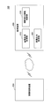
- FIG. 1 is a diagram for explaining an outline of projection of an image in the first embodiment.
- the image projection system 100 of the present embodiment includes an image projection device 200 and a terminal device 300.
- image data for projecting an image in the field of view of the user P based on the information indicating the field of view of the user P wearing the image projector 200 and the projection information. are provided to the image projection apparatus 200.
- the projection information is information that is the origin of the image projected onto the retina of the user P by the image projection apparatus 200, and may be a symbol such as a character or a number, or may be an image. good.
- the image projection apparatus 200 of the present embodiment is a retina projection head mounted display using Maxwell vision.
- Maxwell vision a light beam for imaging based on image data is once converged at the center of the pupil and then projected onto the retina to make a person visually recognize the image represented by the image data without being affected by the function of the human crystalline lens. It is a method.
- the terminal device 300 according to the present embodiment is, for example, a tablet computer or a smartphone, and transmits image data to the image projection device 200.
- the image projection device 200 projects an image onto the retina of the user P by irradiating the light beam for image based on the image data transmitted from the terminal device 300 onto the retina of the user P.
- the image projected directly onto the human retina is viewed as the image represented by the image data if the function of the retina is normal. However, when there is a problem in the function of the retina, the optic nerve or the like, the image projected onto the retina is viewed in a mode different from the image represented by the image data.
- the image projected onto the retina only the limited range of the field of view is viewed.
- the image projected onto the retina is viewed as an image in which a portion of the lost visual field is missing.
- information indicating the visual field in the user's retina is acquired in advance by visual field inspection or the like, and the user is caused to project an image in the visual field by referring to the information indicating the visual field. .
- the terminal device 300 projects information within the field of view of the user P based on the information indicating the field of view of the user P, the information indicating the visual acuity, and the projection information.
- Image data D to be projected is generated and transmitted to the image projector 200.
- the image projection apparatus 200 projects an image based on the image data D onto the retina of the user P.
- the size of the image projected on the user P's retina corresponds to the visual acuity of the user P in the region corresponding to the user's P field of view like the image 201-P.
- FIG. 2 is a top view of the visual field inspection apparatus.
- the image projection apparatus 200 of the present embodiment includes a projection unit 210 and a control unit 230.
- the projection unit 210 of the present embodiment includes a light source 211, a scanning mirror 212, a mirror 213, a mirror 214, a mirror 215, and a projection mirror 216.
- the light source 211 is disposed on the temple 250 of the eyeglass frame.
- the light source 211 emits a light beam L of, for example, a single or a plurality of wavelengths under the instruction of the control unit 230.
- the light ray L is an image light ray for projecting an image on the retina 261 of the eyeball 260 of the user. In the following description, the light ray L is called an image light ray.
- the light source 211 emits, for example, red laser light (wavelength: about 610 nm to 660 nm), green laser light (wavelength: about 515 nm to 540 nm), and blue laser light (wavelength: about 440 nm to 480 nm). It emits red, green and blue laser light.
- the light source 211 according to the present embodiment is realized as a light source 211, for example, a light source in which laser diode chips of RGB (red, green, and blue), a three-color combining device, and a microcollimator lens are integrated.
- the scanning mirror 212 is disposed on the temple 250 of the eyeglass frame.
- the scanning mirror 212 scans the imaging light beam emitted from the light source 211 in the horizontal direction and the vertical direction.
- the scanning mirror 212 is, for example, a MEMS (Micro Electro Mechanical System) mirror.
- the imaging light beam emitted from the light source 211 is reflected by, for example, the mirror 213 and the mirror 214 and enters the scanning mirror 212.
- the control unit 230 is realized by a processor such as a central processing unit (CPU) and a random access memory (RAM) and a read only memory (ROM).
- a processor such as a central processing unit (CPU) and a random access memory (RAM) and a read only memory (ROM).
- the processor and the memory may be mounted, for example, on the same substrate as the substrate on which the scanning mirror 212 (MEMS mirror) is mounted.
- the processor and the memory may be provided in an external device (for example, the terminal device 300 etc.) connected to the image projection device 200.
- the control unit 230 of the present embodiment controls the projection unit 210.
- the control unit 230 causes the light source 211 to emit an image light beam based on the input image data.
- the control unit 230 according to the present embodiment vibrates the scanning mirror 212 (MEMS mirror), scans the imaging light beam emitted from the light source 211, and projects the image on the retina 261.
- MEMS mirror scanning mirror 212
- FIG. 3 is an enlarged view of the vicinity of the projection unit of the image projection apparatus.
- the imaging light beam scanned by the scanning mirror 212 is reflected by the mirror 215 toward the lens 251 of the spectacles-type frame.
- the projection unit 210 is disposed on the surface of the lens 251 on the eyeball 260 side, the imaging light beam scanned by the scanning mirror 212 is incident on the projection mirror 216.
- the projection mirror 216 is a half mirror having a free-form surface or a composite structure of a free-form surface and a diffractive surface in a region 216 a where the image light beam is incident.
- the imaging light beam incident on the projection mirror 216 is converged in the vicinity of the pupil 262 of the eyeball 260 and then projected onto the retina 261.
- the user can recognize the image formed by the image light beam and can visually recognize the outside image by the see-through.
- FIG. 4 is a diagram for explaining the vibration of the first mirror.
- FIG. 4 shows the case where the scanning mirror 212 vibrates from point A to point B.
- a method of scanning an image light beam by the scanning mirror 212 and projecting an image on the retina 261 a method of scanning light at high speed from the upper left to the lower right of the region on which the image is projected (eg, raster scan) ).
- the scanning mirror 212 is larger than a region H (broken line range in FIG. 4) in which the image is projected onto the retina 261 in order to scan the image light beam (light beam L). And vibrate in the horizontal direction (first direction) and in the vertical direction (second direction intersecting the first direction).
- the vibration of the scanning mirror 212 is indicated by reference numeral 50.
- the imaging light beam is scanned at a place where the deflection of the scanning mirror 212 is small.
- FIG. 4 shows an example in which the imaging light beam is scanned in a rectangular shape
- the present invention is not limited to this case, and other cases such as trapezoidal scanning may be used.
- FIG. 5 is a diagram for explaining an example of the hardware configuration of the terminal device.
- the terminal device 300 of the present embodiment includes a display operation device 301, a drive device 302, an auxiliary storage device 303, a memory device 304, an arithmetic processing unit 305, and an interface device 306, which are mutually connected by a bus B.
- the display operation device 301 is a touch panel or the like, and has a display function of displaying information and an input function of inputting information.
- the interface device 306 includes a LAN card and the like, and is used to connect to a network.
- the image projection program executed in the terminal device 300 is at least a part of various programs for controlling the terminal device 300.
- the image projection program is provided, for example, by distributing the recording medium 307 or downloading from the network.
- the recording medium 307 on which the image projection program is recorded is a recording medium for optically, electrically or magnetically recording information such as a CD-ROM, flexible disk, magneto-optical disk, etc., information such as ROM, flash memory etc.
- Various types of recording media can be used, such as a semiconductor memory that electrically records the data.
- the image projection program is installed from the recording medium 307 to the auxiliary storage device 303 via the drive device 302 when the recording medium 307 storing the image projection program is set to the drive device 302.
- the image projection program downloaded from the network is installed in the auxiliary storage device 303 via the interface device 306.
- the auxiliary storage device 303 stores the installed image projection program and also stores necessary files, data, and the like.
- the memory device 304 reads out and stores the image projection program from the auxiliary storage device 303 when the computer is started.
- the arithmetic processing unit 305 implements various processes as described later according to the image projection program stored in the memory unit 304.
- the terminal device 300 includes the display operation device 301 in the present embodiment, the present invention is not limited to this.
- the terminal device 300 may be, for example, a desktop computer or a notebook computer. In that case, the terminal device 300 may have an input device such as a mouse or a keyboard used for inputting information, and an output device such as a display for displaying information, instead of the display operation device 301.
- FIG. 6 is a diagram for explaining the system configuration of the image projection system of the first embodiment.
- the image projection system 100 includes an image projection device 200 and a terminal device 300.
- the image projection device 200 is connected to the terminal device 300 and communicates with the terminal device 300.
- the image projection apparatus 200 and the terminal apparatus 300 perform communication by wireless, but the present invention is not limited to this.
- the image projection device 200 and the terminal device 300 may be connected by any method as long as they are connected in a communicable state.
- the terminal device 300 includes an image generation processing unit 310, an image output processing unit 320, and a visual field and sight information storage unit 330.
- the image generation processing unit 310 refers to the visual field information of the user P of the terminal device 300 and the visual acuity information stored in the visual field and visual acuity information storage unit 330 and is projection information which is information to be projected. To generate image data so that is projected to the user's field of view. Details of the image generation processing unit 310 will be described later.
- the projection information can be mainly required by the user or information of interest.
- the image output processing unit 320 outputs the image data received from the image generation processing unit 310 to an external device. Specifically, the image output processing unit 320 of the present embodiment outputs (sends) the image data received from the image generation processing unit 310 to the image projection apparatus 200.
- the visual field visual acuity information storage unit 330 stores information indicating the visual field of the user P of the image projector 200 and information indicating the visual acuity of the user P.
- the information indicating the visual field is information indicating the area of the retina of the user P, and is information indicating the area of the retina where the image projected by the user P can be viewed.
- the information indicating the visual acuity in the present embodiment is information indicating the visual acuity of the retina itself. Specifically, the information indicating the visual acuity in the present embodiment is different from general visual acuity which changes due to, for example, adjustment of the thickness of the lens by the ciliary muscle, and indicates the function of the macular region of the retina. It is a thing. Details of the visual field visual acuity information storage unit 330 will be described later.
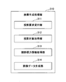
- FIG. 7 is a diagram for explaining the function of the image generation processing unit of the first embodiment.
- the image generation processing unit 310 of the present embodiment includes a projection request reception unit 311, a projection target acquisition unit 312, a visual field visual acuity information acquisition unit 313, and an image data generation unit 314.
- the projection request receiving unit 311 receives a projection request of the input projection information in the display operation device 301 or the like.
- the projection target acquisition unit 312 acquires projection information.
- the projection information may be, for example, content data etc. stored in the auxiliary storage device 33 etc. of the terminal device 300, or even if the terminal device 300 is content data etc. obtained from an external server or storage device etc. good.
- the projection information may be text data or image data including a moving image.
- an imaging apparatus is incorporated, and the projection information may be an image captured by the imaging apparatus incorporated in the image projection apparatus 200.
- the visual field visual acuity information acquisition unit 313 acquires visual field information of the user P of the image projection apparatus 200 and visual acuity information of the user P from the visual field visual acuity information storage unit 330.
- the visual field visual acuity information acquisition unit 313 is a position information acquisition unit that acquires information indicating the position where the projection information is projected.
- the image data generation unit 314 generates image data of an image on which projection information is displayed based on the visual field information, and passes the generated image data to the image output processing unit 320.
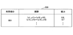
- FIG. 8 is a diagram showing an example of the visual field and sight information storage unit of the first embodiment.
- the visual field information and the visual acuity information are managed as a table associated with the user ID.
- the visual field / visual acuity information storage unit 330 of the present embodiment has a user ID, a visual field, and a visual acuity as items of information, and the visual field and the visual acuity correspond to the user ID.
- the value of the item "user ID" is identification information for identifying the user. In the present embodiment, the user's name or the like may be used instead of the identifier as the information for identifying the user.
- the value of the item “visual field” associated with the user ID is referred to as visual field information
- the value of the item “visual acuity” associated with the user ID is referred to as visual acuity information.
- the value of the item "field of view” is coordinate information indicating the field of view of the user.
- the value of the item "visual acuity” indicates the visual acuity of the user's retina itself.
- the visual field information and the visual acuity information are not associated with each other in the example of FIG. 8, the visual field information and the visual acuity information may be associated with each other in the visual field / acuity information storage unit 330. Specifically, in the visual field and visual acuity information storage unit 330, the area indicated by the visual field information may be managed in association with the visual acuity information indicating the visual acuity of this area.
- the visual acuity information of the present embodiment may be information indicating general visual acuity using a Landolt ring or the like.
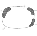
- FIG. 9 is a first diagram showing an example of a field of view. As shown in FIG. 9, missing areas 112, 113, and 114 exist in the field of view 111 of the user P. That is, in the retina of the user P, there is some abnormality at the position corresponding to the defect areas 112, 113, and 114.
- the defect areas 112, 113, and 114 shown in FIG. 9 are reflected even in the projected image. Ru. Therefore, by projecting the information of interest by the user P on areas other than the loss area, even if the user P has a loss area, he / she can view the information of interest or need can do.
- the information projected onto the defect area may be an image continuous with the image projected onto the area not the defect area if it is an image, an image of a single color, etc. In this area, the image light beam is stopped. It is also good.
- the information indicating the visual field of the user includes, for example, an inspection result indicating the presence or absence of visual field loss obtained from a general dynamic visual field inspection or static visual field inspection (visual field inspection with a Humphrey perimeter). It may be acquired as an image and converted into coordinate information by converting an area where the visual field is missing and an area where the visual field is not missing.
- the dynamic visual field inspection is, for example, a visual field inspection using a Goldman perimeter
- the static visual field inspection is, for example, a visual field inspection using a Humphrey perimeter.
- the visual field / visual acuity information storage unit 330 of the present embodiment may be recorded, for example, in a portable recording medium or the like, and may be read from the recording medium by the terminal device 300. Also, the visual field and sight information storage unit 330 may be downloaded from an external server or the like via a network.
- the terminal device 300 only needs to refer to the visual field information storage unit 330, and the method of acquiring the visual field information storage unit 330 by the terminal device 300 is not particularly limited. Further, in the present embodiment, since the terminal device 300 only needs to be able to refer to the visual field information storage unit 330, the visual field information storage unit 330 is stored in an external device capable of communicating with the terminal device 300. good.
- FIG. 10 is a flowchart for explaining the operation of the image generation processing unit of the first embodiment.
- the image generation processing unit 310 causes the projection request receiving unit 311 to select the projection information and determine whether the projection request for the projection information has been received (step S1001). In step S1001, when the projection request is not received, the image generation processing unit 310 stands by until the projection request is received.
- step S1001 when a projection request is received, the image generation processing unit 310 acquires the selected projection information from the projection target acquisition unit 312 (step S1002).
- the image generation processing unit 310 causes the visual field and visual acuity information acquiring unit 313 to acquire visual field information and visual acuity information of the user who has made the projection request from the visual field and visual acuity information storage unit 330 (step S1003).
- the image generation processing unit 310 causes the image data generation unit 314 to generate image data to be delivered to the image output processing unit 320 based on the projection information, the visual field information and the visual acuity information (step S1004).
- the image data generation unit 314 transfers the generated image data to the image output processing unit 320 (step S1005), and ends the process.
- FIG. 11 is a first diagram illustrating an example of image data generated by the image generation processing unit. 11, the case where the image generation processing unit 310 generates image data with reference to visual field information and visual acuity information of the user P having the visual field shown in FIG. 8 will be described.
- the image generation processing unit 310 generates image data in which projection information is included in the area 115 indicating the field of view of the user P.
- An image 201 -P shown in FIG. 11 is an image in which the projection information 202 is included in the area 115 indicated by the visual field information stored in the visual field / visual acuity information storage unit 330. At this time, the size or the like of the character indicating the projection information 202 is set to a size according to the visual acuity information stored in the visual field visual acuity information storage unit 330.
- the image generation processing unit 310 of the present embodiment generates image data representing the image 201-P, and causes the image projection device 200 to project the image 201-P on the retina of the user P.
- the size of the projection information 202 for which the user P made a projection request in the visual field of the user P according to the visual acuity of the user P Can be projected.
- the image data generation unit 314 generates image data of the image 201-P in which information is projected only to the user's field of view, but the present invention is not limited to this.
- the image generation processing unit 310 may generate image data of an image showing the projection information itself, and may transmit the image data to the image projection apparatus 200 together with the visual field information.
- the image projection apparatus 200 controls the vibration of the scanning mirror 212 based on the visual field information by the control unit 230 to adjust the projection position of the image, and projects the image showing the projection information itself in the user's visual field. good.
- the image generation processing unit 310 generates image data of the image 202G indicating the projection information 202 itself, and causes the image output processing unit 320 to output the image data of the image 202G to the image projection device 200 together with the visual field information. .
- the image projection apparatus 200 may control the vibration of the scanning mirror 212 based on the visual field information to adjust the projection position of the image, and project the image data of the image 202G onto the area indicated by the visual field information.
- FIG. 12 is a second diagram showing an example of the field of view.
- the visual field 141 of the user Q is shown.
- the field of view 141 as can be seen from FIG. That is, in the retina of the user Q, there is some abnormality at the position corresponding to the defect area 142. Therefore, the projected image is visually recognized by the user Q as an image in which the area (shaded portion) at the position corresponding to the loss area 142 is missing.
- the image projected on the position corresponding to the area 143 other than the defect area 142 is visually recognized by the user Q.
- FIG. 13 is a second diagram illustrating an example of image data generated by the image generation processing unit. 13, the case where the image generation processing unit 310 generates image data with reference to the visual field information and the visual acuity information of the user Q having the visual field shown in FIG. 12 will be described.
- the image generation processing unit 310 generates image data in which the projection information 203 is included in the area 143 indicating the field of view of the user Q.
- An image 201-Q shown in FIG. 13 is an image in which the projection information 203 is included in an area 143 indicated by the visual field information of the user Q.
- the image generation processing unit 310 of the present embodiment generates image data representing the image 201-Q, and causes the image projection device 200 to project the image 201-Q onto the retina of the user Q.
- image data representing the image 201-Q
- the image projection device 200 causes the image projection device 200 to project the image 201-Q onto the retina of the user Q.
- FIG. 14 is a third diagram illustrating an example of image data generated by the image generation processing unit.
- An image 201-QA shown in FIG. 14 shows an image generated by the image generation processing unit 310 when the visual acuity of the user Q is worse than the example shown in FIG.
- the character indicating the projection information 203 is larger than the character indicating the projection information 203 in the image 201-Q.
- the size of characters, images, symbols, etc. to be projected on the user's retina can be changed according to the user's vision.
- FIG. 15 is a first diagram showing an example of how the projection information in the first embodiment looks.
- FIG. 15 shows how the image 201-Q is projected on the retina of the user Q having the field of view shown in FIG.
- the image 201-Q is projected to a position corresponding to the non-defective area 143 of the user Q's retina, so that the user Q can visually recognize the projection information 203.
- FIG. 16 is a second diagram showing an example of how the projection information appears in the first embodiment.
- FIG. 16 shows how the image 201-QA is projected onto the retina of the user Q having the field of view shown in FIG.
- the character indicating the projection information 203 is enlarged according to the visual acuity information of the user Q.
- the projection information 203 which is in the visual field of the visual field, which is visible to the user in the visual field.
- the image of the search result of the searched term is displayed in the image where the meaning of the term is displayed. Only the image can be extracted, and the extracted image can be displayed in the field of view, and even a person with limited field of view can use a normal electronic dictionary.
- the image data generated by the image generation processing unit 310 of the present embodiment also includes moving image data.
- the moving image data may be projected so that the text data flows in the field of view of the user.
- the image projection apparatus 200 controls the vibration of the scanning mirror 212 based on the visual field information by the control unit 230 to adjust the projection position of the image, and projects the image showing the projection information itself in the user's visual field. good.
- the second embodiment will be described below.
- the second embodiment is different from the first embodiment in that the result of the visual field inspection performed using the image projector 200 is used as visual field information. Therefore, in the following description of the second embodiment, only differences from the first embodiment will be described, and for those having the same functional configuration as the first embodiment, the description of the first embodiment The same reference numerals as the reference numerals used in FIG.
- FIG. 17 is a diagram showing an example of a system configuration of an image projection system according to the second embodiment.
- the image projection system 100A of the present embodiment includes an image projection device 200 and a terminal device 300A.
- the terminal device 300A of the present embodiment includes an image generation processing unit 310, an image output processing unit 320, a visual field and sight information storage unit 330A, and an inspection processing unit 340.
- the inspection processing unit 340 of the present embodiment holds inspection image data corresponding to the visual field inspection image G, and passes the inspection image data to the image output processing unit 320.
- the inspection processing unit 340 of the present embodiment causes the visual field inspection image G to be displayed on the display operation device 301 of the terminal device 300A, receives an input of the inspection result from the user, and transmits the inspection result to the visual field visual information storage unit 330A. Store in Details of the inspection processing unit 340 will be described later.
- the visual field and visual acuity information storage unit 330A of the present embodiment has a visual field information table 331 and a visual acuity information table 332.
- the visual field information table 331 inspection results of visual field inspection of a user wearing the image projection apparatus 200 are stored.
- the visual acuity information table 332 the examination result of the visual acuity examination of the user wearing the image projection apparatus 200 is stored. Details of the visual field information table 331 and the visual acuity information table 332 will be described later.
- FIG. 18 is a diagram for explaining an inspection processing unit of the second embodiment.
- Each unit shown in FIG. 18 is realized by the arithmetic processing unit 305 of the terminal device 300A reading out and executing the visual field inspection program stored in the memory device 304 or the like.
- the inspection processing unit 340 of the present embodiment includes an image data holding unit 341, a display control unit 342, an input receiving unit 343, an image data selection unit 344, and an inspection result storage unit 345.
- the image data holding unit 341 holds image data for visual field inspection corresponding to the image G for visual field inspection and image data for visual acuity inspection corresponding to the image T for visual acuity inspection.
- the image data storage unit 341 of the present embodiment receives an inspection start request, the image data storage unit 341 passes image data corresponding to the inspection to be performed to the image output processing unit 320 and the display control unit 342.
- the image data holding unit 341 holds the inspection image data.
- the inspection image data may also be held by the control unit 230 of the image projection apparatus 200.
- the display control unit 342 When the display control unit 342 receives the inspection image data, the display control unit 342 causes the display operation device 301 of the terminal device 300 to display an input screen of an inspection result including the inspection image. More specifically, the display control unit 342 displays an input screen of an inspection result including the visual field inspection image G and an input screen of an inspection result including the visual acuity inspection image T. In addition, the display control unit 342 of the present embodiment may display a selection screen for selecting a visual field test or a visual acuity test in response to a request for performing an examination.
- the input receiving unit 343 receives an input according to various search operations performed in the display operation device 301. Specifically, the input receiving unit 343 receives an inspection start request, an input on an input screen of an inspection result, and the like.
- the image data selection unit 344 selects image data corresponding to the type of examination accepted by the input acceptance unit 343 from the examination image data retained in the image data retention unit 341 and passes the image data to the display control unit 342.
- the examination result storage unit 345 stores the examination result accepted by the input acceptance unit 343 in the visual field of vision information storage unit 330A in association with information indicating the date and time when the input of the user ID and the examination result is accepted.
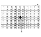
- FIG. 19 is a diagram showing a first example of the visual field inspection image of the second embodiment
- FIG. 20 is a diagram showing a second example of the visual field inspection image of the second embodiment.
- the visual field inspection image G illustrated in FIG. 19 is divided into a plurality of regions in each of the vertical direction and the horizontal direction. In other words, the visual field inspection image G is formed of a set of rectangular areas.
- a number is drawn as an identifier for identifying each area.
- the identifier of the area is not limited to numbers.
- the identifier of the area may be, for example, hiragana or kanji, or letters of an alphabet or another language.
- a gaze point M is formed in the central portion.
- the mark indicating the gaze point M is “+”, but the shape of the mark indicating the gaze point is not limited to this.
- the shape of the mark indicating the fixation point may be any shape as long as the user P can indicate the point to be watched.
- visual impairments there are types of impairments such as discrimination of images and the like but inability to discriminate characters.
- the identifier of the area of the present embodiment may not necessarily be a character.
- an image or the like may be displayed for each area as an area identifier.
- an image of an apple may be displayed in an area where the identifier is “1” and an image of a car may be displayed in an area where the identifier is “2”.
- an image of a star-shaped mark may be displayed in an area where the identifier is “1”
- an image of a heart-shaped mark may be displayed in an area where the identifier is “2”.
- the identifier is not a character but is an image as described above, for example, even for a user who does not have literacy ability, it is possible to distinguish between the visible area and the invisible area in the inspection image. .
- the number of regions included in the visual field inspection image G is 100 in FIG. 19, the number of regions is not limited to this.
- the number of regions in the visual field inspection image G may be determined according to the size of the region onto which the visual field inspection image G is projected. Further, the number of areas in the visual field inspection image G may be such that the user can understand the area seen by the user and the area not seen by the user.
- the number of regions in the visual field inspection image G be such that the region visible by the user and the region invisible by the user can be appropriately grasped without increasing the burden on the user.
- the number of the regions may be determined in advance, for example, from the result of repeating the visual field inspection using the image projection system 100A of the present embodiment.
- region contained in the image G for visual field inspection was made into the rectangle in this embodiment, it is not limited to this.
- the shape of the area included in the visual field inspection image G may be circular, elliptical, or square.
- the image for visual field inspection G1 shown in FIG. 20 is obtained by increasing the size of the identifier drawn in the area as the area is farther from the fixation point M in the central portion.
- the identifier of the area near the fixation point is easily visible to the user P and is separated from the fixation point The identifier of the area is less visible to the user P.
- the visibility of the identifiers around the visual field inspection image G1 can be improved by drawing the larger the identifier located in the position away from the fixation point M centering on the fixation point M.
- the visual field test image G1 can also be used to measure the visual acuity distribution of the retina itself.
- FIG. 21 is a first diagram showing an example of a vision test image of the second embodiment.
- 11 columns of Landolt rings are arranged across six rows.
- coordinates indicating the center of each Landolt ring included in the vision test image T may be associated with the vision test image T.
- the coordinates of the center points P1, P2, and P3 of the Landolt rings 121 to 123 may be output as information for identifying the Landolt ring where the user could not identify the break.
- FIG. 22 is a second view showing an example of a vision test image of the second embodiment.
- the vision test image T1 shown in FIG. 22 five rows of Landolt rings are arranged in three rows, and the Landolt ring of the vision test image T1 is the same as the Landolt rings of the vision test image T shown in FIG. It turns out that it is large compared with.
- the visual acuity examination image corresponding to the visual acuity stage is also provided with a Landolt ring of a size corresponding to the visual acuity stage. It was a thing.
- the size of the Landolt ring to be projected onto the user's retina is selected, and the visual acuity examination image in which the Landolt ring of the selected size is arranged is used. It may be projected on the retina of At this time, the size of the Landolt's ring to be projected on the user's retina may be selected by the user, or may be selected by the examination assistant, for example.
- FIG. 23 is a diagram for explaining a Landolt ring.
- the Landolt ring is a black ring, and the width of the entire ring, the width of the arc, and the width of the open ring (the width of the cut) are 5: 5: 1.
- the visual acuity is 1.0. More specifically, the vision has a diameter of 7.5 mm, an arc width of 1.5 mm, and a cut width of 1.5 mm. It may be a vision 1.0.
- the image projection apparatus 200 may project the vision test image T including the Landolt's ring, which has a size as viewed from a distance of 5 m from the Landolt's ring.
- FIG. 24 is a third diagram showing an example of a vision test image of the second embodiment.
- the position for displaying the Landolt ring shows an image for visual acuity examination.
- one Landolt ring is arranged at the upper left, and in the vision test image T12, one Landolt ring is arranged at the lower left. Further, in the vision test image T13 shown in FIG. 24, one Landolt ring is disposed on the upper right.
- one Landolt ring is arranged for one vision test image, but the present invention is not limited to this.
- a plurality of Landolt rings may be arranged for one vision test image.
- the vision test images different in the position where the Landolt's ring is disposed are sequentially projected on the user's retina, but the present invention is not limited to this.
- the vision test image may be projected on the user's retina as a moving image in which the position of the Landolt ring moves.
- the present embodiment it is possible to associate the user's vision with the vision.
- the distribution of visual acuity in the user's retina can be grasped.
- FIG. 25 is a fourth diagram showing an example of a vision test image of the second embodiment.
- a vision test image T15 shown in FIG. 25 a plurality of Landolt's ring images 151 to 156 having different luminances are arranged.
- the luminance gradually decreases from the image 151 of the Landolt ring to the image 156 of the Landolt ring.
- the luminance required for the user to discriminate the image can be grasped by thus differentiating the luminance of the image of the Landolt ring.
- the Landolt ring may be a black image, or may be an image of a color other than black, for example, blue, red, or green.
- the present embodiment by changing the color of the image of the Landolt's ring, it is possible to examine the presence or absence of a color vision abnormality together with the vision test.
- FIG. 26 is a fifth diagram illustrating an example of the vision test image of the second embodiment.
- the visual acuity test may be performed using an image other than the Landolt's ring.
- the vision test image T16 shown in FIG. 26 includes an ETDRS (Early Treatment of Diabetic Retinopathy Study) chart.
- the difference between the sizes of targets between rows is 0.1 log MAR unit, and five targets are arranged in one row.
- the character to be a target is Sloan Letter set (10 characters of C, D, H, K, N, O, R, S, V, Z) of Sloan font.
- the distance between each target is one target, and the result is not digitized but the numerical value by the targets.
- the visual acuity test may be performed using a target other than the Landolt ring.
- the targets other than the Landolt's ring are, for example, a tumbling E chart etc. in addition to the ETDRS chart.
- FIG. 27 is a diagram showing an example of an image used for examination of contrast sensitivity
- FIG. 28 is a diagram showing an example of an image used for examination of astigmatism.
- the vision test image T of the present embodiment may include, for example, a test image of contrast sensitivity shown in FIG.
- Images 171 and 172 shown in FIG. 27 are images for projecting a color gradation over the entire field of view.
- the contrast sensitivity of the user can be measured by thus projecting the gradation of the color on the user's visual field and inputting the color recognizable by the user as the inspection result.
- the image projected on the entire visual field is not an image of gradation of color, but a plurality of images in which the entire visual field has the same color are prepared, and the plurality of images are sequentially projected. It is also possible to realize color gradation.
- the vision test image T of the present embodiment may include the image 181 and the image 182 for astigmatism examination shown in FIG. By including these images in the visual acuity examination image T, it can be examined whether the user is astigmatic or not.
- FIG. 29 is a flowchart illustrating processing of the inspection processing unit of the second embodiment.
- the terminal device 300A determines whether the input receiving unit 343 has received a request for starting a visual field inspection (step S2901). If the start request has not been received in step S2901, the inspection processing unit 340 proceeds to step S2911 described later.
- step S 2901 when the start request is received, the inspection processing unit 340 causes the image data selection unit 344 to select and read out the image data for visual field inspection from the image data held by the image data holding unit 341, and outputs the image.
- the image data for visual field inspection is transferred to the processing unit 320 and the display control unit 342 (step S2902).
- the image output processing unit 320 transmits the image data for visual field examination to the image projection apparatus 200 (step S2903).
- the projection unit 210 scans an image light beam based on the visual image data for visual field inspection onto the user's retina and performs visual field inspection. Make the image G visible to the user.
- the display control unit 342 causes the display operation device 301 of the terminal device 300A to display an input screen of an inspection result including the visual field inspection image G based on the inspection image data (step S2904). Details of the inspection result input screen will be described later.
- the inspection processing unit 340 causes the input receiving unit 343 to determine whether or not the input of the inspection result of the visual field inspection is received on the input screen (step S2905).
- the input receiving unit 343 proceeds to step S2908 described later.
- step S2905 when the input of the examination result is accepted, the input accepting unit 343 determines whether or not an instruction to save the examination result is accepted (step S2906). In step S2906, when the storage instruction is not received, the input receiving unit 343 proceeds to step S2910 described later.
- step S2906 when the input of the storage instruction is received, the inspection processing unit 340 causes the inspection result storage unit 345 to store the input inspection result in the visual field and vision information storage unit 330A (step S2907), and the processing ends.
- step S2905 when the input of the test result is not received, the input receiving unit 343 determines whether a predetermined time has elapsed (step S2908). If the predetermined time has not elapsed in step S2908, the input accepting unit 343 returns to step S2905.
- step S2908 when the predetermined time has elapsed, the inspection processing unit 340 causes the display control unit 342 to cause the terminal device 300 to display that the execution of the visual field inspection has not been performed normally (step S2909), and the process is ended. Do.
- step S2906 when the storage instruction is not received, the input receiving unit 343 determines whether a predetermined time has elapsed (step S2910). In step S2910, when the predetermined time has not elapsed, the input accepting unit 343 returns to step S2906.
- step S2910 If the predetermined time has elapsed in step S2910, the inspection processing unit 340 proceeds to step S2909.
- step S2901 the input receiving unit 343 determines whether the start request of the visual acuity inspection is received (step S2911). In step S2911, when the start request for the visual acuity examination is not received, the inspection processing unit 340 returns to step S2901.
- step S 2911 when the start request for the visual acuity examination is received, the examination processing unit 340 causes the image data selection unit 344 to select and read the visual acuity examination image data from the image data held by the image data holding unit 341. Then, the visual field inspection image data is passed to the image output processing unit 320 and the display control unit 342 (step S2912), and the process proceeds to step S2903.
- FIG. 30 is a diagram illustrating an example of an inspection result input screen according to the second embodiment.
- the visual field inspection image G is displayed on the inspection result input screen 101 shown in FIG. Further, on the input screen 101, a message 102 for selecting a read numeral in the visual field inspection image G and a button 103 for instructing storage of the inspection result are displayed.
- the message 102 is "Please touch the number read by the user", which is the content prompting the user to select the number visually recognized in the visual field inspection image G. But it is not limited to this.
- the message 102 may be, for example, content for prompting the user to select a number which can not be visually recognized in the visual field inspection image G.
- the content of the message 102 may be set in advance by the administrator of the image projection system 100A or the like. Also, for example, it may be set by the user whether to select a read digit or to select an unreadable digit.
- the visual field information table 331 and the visual acuity information table 332 stored in the visual field and visual acuity information storage unit 330A of the present embodiment will be described.
- the visual field information table 331 -P of the user P will be described with reference to FIGS. 31 to 36.
- FIG. 31 is a first diagram showing an example of how the visual field inspection image of the second embodiment looks.
- FIG. 31 shows an example of how the user P having the visual field shown in FIG. 9 looks at the visual field inspection image G.
- the user P has missing areas 112, 113, 114 (see FIG. 9).
- the defective areas 112, 113, and 114 are reflected also in the visual field inspection image G.
- the visual field inspection image G is visually recognized by the user P as an image in which the area (shaded area) at the position corresponding to the defect areas 112, 113, and 114 is missing. Therefore, the number drawn in the area at the position corresponding to the missing area is not visually recognized by the user.
- the area included in the loss area 112 is an area with identifiers 1, 2, 11, 21 and the area included in the loss area 113 is an area with identifiers 9, 10, 20, 30. is there. Therefore, these numbers are numbers that can not be read by the user P.
- FIG. 32 is a first diagram illustrating an example of an input screen in a state in which a test result is input in the second embodiment.
- An input screen 101A shown in FIG. 32 shows an example in which the inspection result of the user P is input on the input screen 101.
- the numbers of the areas included in the respective missing areas 112 to 114 are not selected, and the numbers of the areas other than the missing areas 112 to 114 are selected.
- the selected area in the image for visual field inspection G, the selected area is made to look brighter than the area not selected, but the present invention is not limited to this.
- the selected area and the non-selected area be displayed in different modes in the visual field inspection image G so that they can be distinguished.
- the user P has selected 3 to 8, 12 to 19, 22 to 29, 31 to 89, 91 to 99 as the numbers read. Therefore, in the image G for visual field inspection displayed on the input screen 101A, it can be understood that the area in which the number selected by the user P is drawn is the visual field of the user P.
- the inputted examination result is stored as the visual field information table 331 in the visual acuity information storage unit 330A.
- FIG. 33 is a first diagram showing an example of the visual field information table of the second embodiment.
- the visual field information table 331 of the present embodiment is provided for each user, and FIG. 33 shows the visual field information table 331 -P of the user P.
- the visual field information table 331 -P of the present embodiment has, as items of information, a user ID, an examination date, an input time, a read number, and a not read number.
- the item "user ID" is associated with other items.
- information including the value of each item is referred to as visual field inspection result information.
- the visual field test result information of the present embodiment corresponds to visual field information indicating the visual field of the user.
- the value of the item “examination date” is information indicating the date on which the visual field examination was performed.
- the item “input time” value is information indicating the time at which the inspection result of the visual field inspection is input in the terminal device 300. That is, the value of the item “input time” is information indicating the time when the visual field examination was performed.
- the value of the item “read number” indicates a number read by the user in the visual field inspection image G.
- the value of the item “read number” indicates the number drawn in the area selected as the read number in the visual field inspection image G displayed on the inspection result input screen 101.
- the value of the item “unreadable number” indicates a number that can not be read by the user in the visual field inspection image G.
- the value of the item “unreadable digit” indicates the numeral drawn in the area not selected as the readable digit in the visual field inspection image G displayed on the inspection result input screen 101.
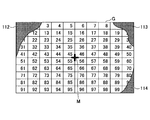
- FIG. 34 is a second view showing an example of how the field-of-view image of the second embodiment looks.
- FIG. 34 shows an example of how the user Q having the visual field shown in FIG. 12 looks at the visual field inspection image G.
- the user Q has a defect area 142 (see FIG. 12).
- the visual field inspection image G is visually recognized by the user Q as an image in which the area (hatched portion) at the position corresponding to the lack area 142 is missing. Therefore, in the example of FIG. 34, the numbers drawn in the area at the position corresponding to the missing area 142 are numbers that can not be read by the user Q.
- FIG. 35 is a second diagram showing an example of the input screen in the state in which the visual field inspection result is input in the second embodiment.
- the input screen 101B shown in FIG. 35 shows an example in which the inspection result of the user Q is input on the input screen 101.
- the numbers of the areas included in the loss area 142 are not selected, and the numbers of the areas other than the loss area 142 are selected.
- the user Q has selected 5 to 10, 15 to 20, 25 to 30, 35 to 40, 45 to 50, 55 to 59, and the like as the numbers read. Therefore, it can be understood that the area in which the number selected by the user Q is drawn is the field of view of the user Q.
- the examination result is stored as the visual field information table 331-Q in the visual field / visual acuity information storage unit 330A.
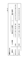
- FIG. 36 is a second diagram showing an example of the visual field information table of the second embodiment.
- the result of the visual field inspection performed by the user Q with the user ID 002 is 10:00 on 2016/10/10 and 18:00 on 16/31/2016. You can see that it was input to
- the visual field information table 331 can be generated by performing visual field inspection with a simple configuration and using the inspection result as visual field information indicating the user's visual field.
- the visual field information table 331 stored in the terminal device 300A may be stored, for example, in a server such as a medical institution.
- the visual field inspection image G is described as having a size that covers the visual field of the user, but the present invention is not limited to this.
- the image projector 200 may be provided with a mechanism for detecting the moving direction of the pupil.
- a mechanism for detecting the moving direction of the pupil by providing such a mechanism in the image projection apparatus 200, it is possible to change the irradiation direction of the image light beam from the light source 211 to the moving direction of the pupil in the moving direction of the user's pupil.
- the user can view the same visual field inspection image G both after moving the pupil and before moving it.
- the user does not have to turn to a fixed direction, and can perform visual field inspection in a free posture.
- the visual field inspection image G can be always viewed by the user during the inspection without being influenced by the posture or the like of the user, and the accuracy of the inspection can be improved.
- the visual field information table 331 of the present embodiment for example, instead of the value of the item “read numeral” and the value of the item “unreadable numeral”, the area indicated by each identifier in the visual inspection image G Coordinate information indicating the position may be used. Further, the visual field information table 331 may have, as items of information, for example, coordinate information indicating the position of the area indicated by the value of the item “read number” and the value of the item “unreadable number”.
- the coordinate information may be acquired, for example, from the image data for visual field inspection, or may be acquired from, for example, a table in which an identifier of each area and coordinate information specifying the identifier and the corresponding area are associated. . This table may be given to the terminal device 300 in advance.
- the visual field inspection result information may include the image data of the visual field inspection image G in the state where the area is selected. That is, in the present embodiment, the visual field inspection result information may hold the image data of the visual field inspection image G in which the area is selected as shown in FIGS. 32 and 35 as one item of the visual field inspection result information.
- the brightness (brightness) of the visual field inspection image G may be changed stepwise, and the inspection result may be input each time.
- the item “brightness of the visual field inspection image G” may be added to the visual field information table 331, and the value of the item “brightness of the visual field inspection image G” may be included in the inspection result information.
- the visual field corresponding to the brightness of the user can be specified by inputting the inspection result for each brightness of the visual field inspection image G.
- FIG. 37 is a diagram showing an example of how the vision test image of the second embodiment is viewed.
- FIG. 37 shows an example of how the user Q having the visual field shown in FIG. 12 looks at the visual acuity examination image T.
- the user Q has a defect area 142. Therefore, for the user Q, as shown in FIG. 37, the vision test image T is visually recognized as an image in which the area (shaded portion) at the position corresponding to the defect area 142 is missing. Therefore, the Landolt ring drawn in the area at the position corresponding to the defect area is not visually recognized by the user Q. Therefore, in the example of FIG. 37, the Landolt's ring drawn in the area included in the missing area 142 is an area where the user Q can not determine the break.
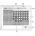
- FIG. 38 is a diagram showing an example of an input screen in a state where the visual acuity test result is input in the second embodiment.
- An input screen 101C illustrated in FIG. 38 illustrates an example in which the result of the visual field inspection of the user Q is input on the input screen 101.
- a vision test image T including Landolt rings of different sizes is sequentially projected onto the retina of the user Q.
- the user Q reads out the direction of the break of the Landolt ring projected to an area other than the defect area 142, and the test assistant reads the direction of the break by the user. Select at 101C.
- an identifier or the like for specifying each Landolt ring may be provided at the center or in the vicinity of the Landolt ring.
- a number serving as an identifier for identifying a Landolt ring may be assigned to the center of each Landolt ring.
- the Landolt's ring of the region included in the defect region 142 is not selected on the input screen 101C, and the Landolt's ring of the region other than the defect region 142 is selected.
- the visual acuity test can be performed in this manner to measure the visual acuity of the user Q's visual field. Further, in the present embodiment, simultaneously with the visual acuity examination, a visual field examination as to whether or not a defect area exists in the visual field of the user Q can also be performed.
- the result of the vision test is stored in the vision information table 332-Q.
- FIG. 39 is a first diagram showing an example of the visual acuity information table of the second embodiment.
- the visual acuity information table 332 of the present embodiment is provided for each user, and FIG. 39 shows the visual acuity information table 332 -Q of the user Q.
- the visual acuity information table 332-Q of the present embodiment has, as items of information, a user ID, an examination date, an input time, a Landolt ring which could not be discriminated, and a Landolt ring which could be discriminated.
- the item "user ID" is associated with other items.
- information including the value of each item is the visual acuity information.
- the value of the item “Landolt ring that could not be determined” indicates the Landolt ring on which the user could not determine the break in the vision test image T.
- the value of the item “Landolt ring that could not be determined” is an identifier that specifies the Landolt ring that has not been selected as the Landolt ring whose break has been determined in the visual acuity examination image T displayed on the input screen 101C. .
- the value of the item “discriminated Landolt ring” indicates a Landolt ring at which the user can discriminate a break in the vision test image T.
- the value of the item “discriminated Landolt ring” is an identifier for identifying the Landolt ring selected as the Landolt ring whose break has been discriminated in the visual acuity examination image T displayed on the input screen 101C.
- the visual information table 332 -Q shown in FIG. 39 indicates that the result of the visual acuity examination performed by the user Q with the user ID 002 was input at 10:00 on 2016/4/10.
- each of the values of the item “Landolt ring that could not be determined” and the value of “Landolt ring that could be determined” was used as an identifier for identifying the Landolt ring, but is not limited thereto.
- the values of the items “undetected Landolt ring” and “judged Landolt ring” may be, for example, the coordinates of the central point of the Landolt ring selected on the input screen 101C.
- FIG. 40 is a second diagram showing an example of the visual acuity information table of the second embodiment.
- the visual acuity information table 332A-Q shown in FIG. 40 shows an example of the examination result of visual acuity when a moving image in which one Landolt's ring moves is projected on the retina of the user Q.
- the value of the item “discriminated Landolt ring” is coordinate information indicating the area in which the Landolt ring whose break has been determined by the user Q is displayed in the visual acuity examination image T. is there.
- the value of the item “discriminated Landolt ring” is coordinate information indicating a region where the Landolt ring whose break has been determined by the user Q is displayed in the visual acuity examination image T.
- the value of the item “Landolt ring that could not be determined” is coordinate information indicating a region in which the Landolt ring for which a break was not determined by the user Q was displayed in the visual acuity examination image T.
- the coordinates here are the coordinates of the central point of the Landolt ring.
- “discrimination of Landolt ring break” refers to visual recognition of the Landolt ring, and the case in which the direction of the break point is correctly determined and the Landolt ring could be recognized, but the direction of the break point is correct. It may include both the case where it is not determined and the case.
- each region of the visual field inspection image G Since it corresponds to the position on the retina, it is possible to perform a visual field test at each position on the retina by examining the visible or invisible in each of the areas.
- the vision test image T including the image of the visual target used for the vision test is directly made to a predetermined position on the retina. Therefore, according to the present embodiment, the eyesight of the retina itself can be measured. Furthermore, in the present embodiment, the distribution of visual acuity in the retina can be measured.
- the image projection apparatus 200 has a shape like general glasses, but is not limited to this.
- it may be shaped like goggles covering both eyes of the user P.
- the area H (see FIG. 4) on which the image is projected in the image projection device 200 be sized to cover the field of view of the user.
- the size that covers the user's field of vision is, for example, a size in which the image projected onto the retina covers about 60 degrees on the nose side and upper side, about 70 degrees on the lower side, and about 90 to 100 degrees on the ear side. It is.
- the area on which the image (the test image) is projected has a size that covers the user's (subject's) field of view, even for users who have no visual field defects, retina or optic nerve, etc. , Can perform appropriate visual field inspection.
- the region H where the image is projected is “under about 60 degrees on the nose side and upper side with one eye, It may be smaller than about 70 degrees, and about 90 to 100 degrees on the side of the ear.
- the input may be performed after removing the attached image projection apparatus 200, or the terminal with the eye not performing the visual field inspection You may look at the screen of apparatus 300A, and may input.
- the inspection assistant may be requested to input the terminal device 300A.
- the user may convey the area where the characters can be read to the inspection assistant by reading the characters that have been viewed.
- the third embodiment will be described below with reference to the drawings.
- the third embodiment is different from the second embodiment in that the function of the terminal device of the second embodiment is provided in a server outside the terminal device. Therefore, in the following description of the third embodiment, components having the same functional configuration as the second embodiment are given the same reference numerals as the symbols used in the description of the second embodiment, and the description thereof Omit.
- FIG. 41 is a view for explaining the system configuration of the image projection system of the third embodiment.
- An image projection system 100B of the present embodiment includes an image projection device 200, a terminal device 300B, and a server 400.
- the image projection apparatus 200 and the terminal apparatus 300B are one in the example of FIG. 25, the number of the image projection apparatus 200 and the terminal apparatus 300B included in the image projection system 100B may be any number.
- the terminal device 300 ⁇ / b> B of the present embodiment receives image data from the server 400 and transmits the received image data to the image projection device 200.
- the terminal device 300B of the present embodiment displays a screen instructed from the server 400, and transmits information input on the screen to the server 400.
- the server 400 of the present embodiment is connected to the terminal device 300B via a network.
- the server 400 includes a visual field of sight information database 330B, an image generation processing unit 310, an inspection processing unit 340A, and an image data transmission unit 350.
- the visual field information and the visual acuity information input in the terminal device 300B are stored in association with the user ID and the information indicating the date and time each information was input. There is. Specifically, in the visual field / visual acuity information database 330B, for example, when there are a plurality of terminal devices 300B, the visual field information table 331 and the visual acuity information table 332 input in each of the plurality of terminal devices 300B are user IDs. It is stored every time.
- the examination processing unit 340A of the present embodiment causes the display operation device 301 of the terminal device 300B to display an input screen of examination results including the visual field examination image data and the visual acuity examination image data.
- the input receiving unit 343 receives information input on the input screen of the terminal device 300B.
- the image data transmission unit 350 of the present embodiment transmits the image data for visual field examination, the image data for visual acuity examination, and the image data generated by the image generation processing unit 310 to the terminal device 300B.
- the terminal device 300 ⁇ / b> B outputs the image data for visual field examination, the image data for visual acuity examination, and the image data generated by the image generation processing unit 310 to the image projection device 200.
- the inspection processing unit 340A and the image generation processing unit 310 are provided in the server 400 as described above, the processing load on the terminal device 300B can be reduced.
- the image generation processing unit 310 and the inspection processing unit 340A are provided in the server 400, but the present invention is not limited to this.
- the image generation processing unit 310 and the inspection processing unit 340A may be provided in different servers 400, respectively.
- the visual field visual information database 330B may be provided so that visual field information for each user obtained by the visual field inspection by the inspection processing unit 340A is stored and can be referred to by the image generation processing unit 310.
- the fourth embodiment will be described below with reference to the drawings.
- the fourth embodiment is different from the second embodiment in that the server distributes an application including an inspection processing unit, an image generation processing unit, and an image output processing unit to the terminal device. Therefore, in the following description of the fourth embodiment, components having the same functional configuration as the second embodiment are given the same reference numerals as the symbols used in the description of the second embodiment, and the description thereof Omit.
- FIG. 42 is a diagram for explaining the system configuration of an image projection system according to the fourth embodiment.
- the image projection system 100C of the present embodiment includes an image projection device 200, a terminal device 300C, and a server 400A.
- the server 400A of the present embodiment has an application distribution unit 410.
- the server 400A also has an application 420 for realizing the functions of the image generation processing unit 310, the image output processing unit 320, and the inspection processing unit 340.
- the application distribution unit 410 when the application distribution unit 410 receives a distribution request of the application 420 from the terminal device 300C, the application distribution unit 410 distributes the application 420 to the terminal device 300C that has received the distribution request.
- the terminal device 300C to which the application 420 is distributed is the terminal device 300A including the image generation processing unit 310, the image output processing unit 320, and the inspection processing unit 340. Therefore, in the present embodiment, the terminal device 300C after the application 420 is distributed performs the visual field inspection with only the terminal device 300C to acquire the visual field information and the visual acuity information of the user, and the acquired visual field information and the visual acuity Image data generated based on the information can be provided to the image projector 200.
- the application 420 distributed by the server 400A includes the functions of the image generation processing unit 310, the image output processing unit 320, and the inspection processing unit 340, but is not limited thereto.
- the application 420 delivered from the server 400A to the terminal device 300C may include, for example, only the functions of the image generation processing unit 310 and the image output processing unit 320.
- the terminal device 300 ⁇ / b> C may receive the distribution of the application from the server 400 ⁇ / b> A and may acquire the view information of the user.
- the fifth embodiment will be described below with reference to the drawings.
- the fifth embodiment is different from the first embodiment described above in that the position where the projection information is projected is set by the user. Therefore, in the following description of the fifth embodiment, components having the same functional configuration as the first embodiment are given the same reference numerals as the symbols used in the description of the first embodiment, and the description thereof Omit.
- FIG. 43 is a diagram for explaining the system configuration of an image projection system according to the fifth embodiment.
- the image projection system 100D of the present embodiment includes an image projection device 200 and a terminal device 300D.
- the terminal device 300D of the present embodiment includes an image generation processing unit 310A, an image output processing unit 320, a projection setting unit 355, and a projection position table 360.
- the image generation processing unit 310A of the present embodiment acquires projection position information stored in the projection position table 360 instead of the visual field information. Details of the image generation processing unit 310A will be described later.
- the projection setting unit 355 of the present embodiment sets the projection location of the projection information. Specifically, the projection setting unit 355 causes the display operation device 301 of the terminal device 300D to display a setting screen for setting the projection position of the projection information, and stores the input setting in the projection position table 360.
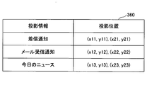
- the projection position table 360 stores projection information and a projection position in association with each other for each user ID. Details of the projection position table 360 will be described later.
- FIG. 44 is a first diagram for explaining the function of the image generation processing unit of the fifth embodiment.
- the image generation processing unit 310A of the present embodiment has a projection determination unit 311A instead of the projection request reception unit 311, and has a projection position acquisition unit 313A instead of the visual field / acuity information acquisition unit 313.
- the projection determination unit 311A determines whether to output projection information to the image projection apparatus 200. Specifically, the projection determination unit 311A determines whether or not it is time to project the projection information set in the projection position table 360 on the image projector 200.
- the projection target acquisition unit 312 acquires projection information such as text data to be projected and image data.
- the projection position acquisition unit 313A acquires, from the projection position table 360, information indicating the projection position associated with the projection information.
- FIG. 45 is a view showing an example of a projection position table of the fifth embodiment.
- the projection position table 360 of this embodiment has projection information and a projection position as items of information, and both are associated with each other.
- the value of the item “projection information” indicates information to be projected on the user's retina in the image projector 200.
- the value of the item “projection position” indicates projection position information indicating the projection position of projection information on the user's retina. Specifically, the value of the item “projection position” indicates the coordinates of the upper left point of the rectangle and the coordinates of the lower right point in the projection area (rectangle) of the projection information. Note that the value of the item “projection position” may be coordinates of four points of the rectangular projection area.
- the projection information “incoming call notification” is projected inside a rectangle whose coordinates of the upper left point are (x11, y11) and whose lower right coordinates are (x21, y21).
- FIG. 46 is a flowchart for explaining the processing of the projection setting unit of the fifth embodiment.
- the projection setting unit 355 determines whether a request for setting the projection position of the projection information has been received (step S4601).
- step S4601 when the setting request is not received, the projection setting unit 355 waits until the setting request is received.
- step S4601 when the setting request is received, the projection setting unit 355 causes the display operation device 301 of the terminal device 300D to display a selection screen of projection information (step S4602), and receives selection of projection information in the selection screen ( Step S4603).
- the projection setting unit 355 displays a setting screen of the projection position of the selected projection information (step S4604), and receives the setting of the projection position (step S4605).
- the projection setting unit 355 associates the selected projection information with the position information indicating the set projection position, stores the information in the projection position table 360 (step S4606), and ends the processing.
- FIG. 47 is a flowchart for explaining the processing of the image generation processing unit of the fifth embodiment.
- the image generation processing unit 310A of the present embodiment determines whether it is time to project projection information by the projection determination unit 311A (step S4701). Specifically, for example, when the projection information is an incoming notification, the projection determination unit 311A determines that it is a timing to project the projection information when the terminal device 300D receives the incoming notification.
- step S4701 when it is not the timing to project, the projection determination unit 311A stands by until the corresponding timing is reached.
- step S4701 when it is the timing to project, the image generation processing unit 310A refers to the projection position table 360 and acquires projection position information corresponding to the projection information. Also, the image generation processing unit 310A causes the projection target acquisition unit 312 to acquire projection information (step S4702).
- the image generation processing unit 310A causes the image data generation unit 314 to generate image data of an image indicating projection information (step S4703).
- the image data generation unit 314 outputs the generated image data to the image output processing unit 320 (step S4704), and the process ends.
- the image data transmitted to the image output processing unit 320 is transmitted to the image projection apparatus 200 by the image output processing unit 320.
- FIG. 48A is a diagram showing an example of a selection screen of projection information according to the fifth embodiment
- FIG. 48B is a diagram showing an example of a setting screen of projection positions of projection information.
- a message 322 for prompting selection of projection information, a list 323 of projection information, and a button 234 for transitioning the selection screen 321-1 to the setting screen 321-2 are displayed.
- the selection screen 321-1 displayed on the display operation device 301 is displayed as shown in FIG. It changes to the setting screen 321-2 shown in FIG.
- the setting screen 321-2 displays a message 325 prompting specification of a projection position, and an image 326 indicating a projection area by the image projection apparatus 200.
- the projection setting unit 355 of the present embodiment identifies the incoming notification and the area 327.
- Coordinate information is associated with the coordinate information and stored in the projection position table 360.
- the projection setting unit 355 selects the clock and coordinate information for specifying the area 328. It associates and stores in the projection position table 360.
- the projection position may be designated by, for example, the user touching a desired area on the image 326 in the setting screen 321-2 or surrounding the area with a finger.
- the terminal device 300D may hold the visual acuity information of the user, and the image generation processing unit 310A acquires and projects the visual acuity information of the user along with the projection position and the projection information.
- the size of the characters, numbers, symbols, etc. of the projection information may be set according to the visual acuity information.
- FIG. 49 is a diagram showing an example in which projection information is projected to a designated position.
- FIG. 49 shows a part of the field of view of the user.
- the incoming call notification is projected so as to be visible at the position of the area 327 of the field of view, and the clock is projected so as to be visually recognized at the position of the area 328.
- the projection information can be projected on any position on the user's retina. Therefore, according to the present embodiment, it is not necessary for the user to move the line of sight or adjust the focus in order to visually recognize the projected information.
- the image projection system 100D of the present embodiment if the driver of a mobile object such as a car is equipped with the image projection apparatus 200 and the traffic information etc. is projected to a position designated in advance, the driver looks at the line of sight. You can see traffic information without moving it.
- the doctor or the like in the operation is mounted with the image projection apparatus 200, and the numerical value, information, etc. which are required to be referred in the operation are used as projection information. You can see the information you need without turning your eyes off the operative field.
- the image generation processing unit 310A, the projection setting unit 355, and the projection position table 360 according to the present embodiment may be provided in a server outside the terminal device 300.
- the image generation processing unit 310A and the projection setting unit 355 of the present embodiment may be distributed to the terminal device 300 as an application from an external server.
- FIG. 50 is a second diagram for explaining the function of the image generation processing unit of the fifth embodiment.
- An image generation processing unit 310B illustrated in FIG. 50 includes a projection determination unit 311A, a projection target acquisition unit 312A, a projection position acquisition unit 313A, and an image data generation unit 314, and converts voice input from the outside into character information.
- the converted character information is used as projection information.
- the projection target acquisition unit 312A of the present embodiment has a voice acquisition unit 315 and a character information conversion unit 316.
- the voice acquisition unit 315 acquires, for example, voice input from a voice input device such as a microphone of the terminal device 300D.
- the character information conversion unit 316 analyzes the voice acquired by the voice acquisition unit 315 and converts it into character information.
- the image generation processing unit 310B of the present embodiment converts the voice obtained by the text information conversion unit 316 into text information to be projection information. Then, by projecting this projection information to an arbitrary field of view of the user, the user can visually recognize the voice as characters.
- this configuration if this configuration is used, even a user with hearing impairment and visual impairment can perceive voice information. Therefore, if this configuration is applied to, for example, voice guidance in an art museum or the like, or a voice guide in kabuki, it is possible to obtain information that the user has difficulty obtaining due to a fault.
- voice information can be moved to any position in the field of view as character information and projected, character information converted from voice can be obtained without interrupting the area of interest. Will be visible.
- the sixth embodiment will be described below with reference to the drawings.
- the sixth embodiment is different from the first embodiment in the shape of the mirror in the image projector. Therefore, in the following description of the sixth embodiment, only differences from the first embodiment will be described, and for those having the same functional configuration as the first embodiment, the description of the first embodiment.
- FIG. 51 is a top view of the image projector of the sixth embodiment.
- the image projection apparatus 200A of the present embodiment can be applied to the image projection system described in the first to fifth embodiments.
- the image projection device 200A of the present embodiment includes a projection unit 210A and a control unit 230.
- the projection unit 210A of the present embodiment includes a light source 211, a scanning mirror 212A, a reflection mirror 215A, and a projection mirror 216.
- the projection unit 210A of this embodiment does not have the mirror 213 and the mirror 214, has the scanning mirror 212A instead of the scanning mirror 212, and has the reflecting mirror 215A instead of the reflecting mirror 215. Is different from the projection unit 210 of the second embodiment.
- the traveling direction of the light beam incident on the projection mirror 216 in the projection mirror 216 is taken as the X direction
- the direction orthogonal to the X direction in the projection mirror 216 is taken as the Y direction.
- the scanning mirror 212A is, for example, a MEMS mirror, and scans the laser beam (light beam) L emitted from the light source 211 in the two-dimensional direction of the horizontal direction and the vertical direction. In addition, the scanning mirror 212A two-dimensionally scans the light beam L emitted from the light source 211 to obtain projection light for projecting an image on the retina 26 of the eyeball 260 of the user.
- the reflection mirror 215A reflects the light beam L scanned by the scanning mirror 212A toward the lens 251.
- a projection mirror 216 having a free-form surface is provided on the surface of the lens 251 on the eyeball 260 side of the user.
- the projection mirror 216 projects an image on the retina 261 by scanning the scanning mirror 212A and irradiating the light ray L reflected by the reflection mirror 215A to the retina 261 of the eyeball 260. That is, the user can recognize an image by the afterimage effect of the laser beam projected onto the retina 261.
- the projection mirror 216 is designed such that the convergence position of the light beam L scanned by the scanning mirror 212A is the pupil 262 of the eyeball 260.
- the ray L is incident on the projection mirror 216 almost immediately (that is, approximately in the ⁇ X direction).
- the distance from the reflection mirror 215A to the convergence position of the pupil 262 can be shortened, and the image projection apparatus 200A can be miniaturized. .
- FIG. 52 is a diagram showing an optical path of a light beam in the image projector according to the comparative example.
- light beams L0 to L2 are light beams scanned in the horizontal direction by the scanning mirror 212A, and are irradiated to the projection mirror 216 from the ⁇ X direction.
- a ray L0 is a ray corresponding to the center of the image
- rays L1 and L2 are rays corresponding to the edge of the image.
- the rays L0 to L2 are reflected by the regions R0 to R2 of the projection mirror 216, respectively.
- the reflected light rays L 0 to L 2 converge at the pupil 262 located at the center of the iris 263, pass through the lens 264, and reach the retina 261.
- Region R0 is a region that reflects light ray L0 corresponding to the center of the image.
- the region R1 is a region from the region R0 in the -X direction (the direction in which the light beams L0 to L2 are incident).
- the region R2 is a region in the + X direction from the region R0. Rays L 0 to L 2 will cross near the pupil 262 for Maxwell viewing. However, the in-focus positions F0 to F2 of the respective light beams L0 to L2 deviate from the retina 261.
- the light ray L0 reflected by the projection mirror 216 is incident on the lens 264 as substantially parallel light and is focused near the retina 261.
- the light beam L1 reflected by the projection mirror 216 enters the lens 264 as diffused light. For this reason, the light beam L1 is focused farther than the retina 261.
- the light beam L2 reflected by the projection mirror 216 is incident on the lens 264 as convergent light. For this reason, the light beam L2 is focused closer to the retina 261.
- the in-focus position F1 is farther from the projection mirror 216 than the retina 261. It is the distance D1 between the in-focus position F1 and the retina 261.
- the in-focus position F2 is closer to the projection mirror 216 than the retina 261.
- the distance D2 between the in-focus position F2 and the retina 26 is obtained.
- the projection mirror 216 is a free-form surface, and if it is attempted to cause the pupil 262 to converge the light rays L0 to L2 incident on the projection mirror 216 from the -X direction, This is because the curvatures of the regions R0 to R2 of the mirror 216 differ in the X direction and / or an optical path difference of the light beams L0 to L2 occurs.
- the region R2 has a curvature larger than that of R1. That is, the region R2 has a larger condensing power than R1. Therefore, the in-focus position F2 is closer to the light source than F1.
- the in-focus position F2 is closer to the light source than F1.
- the optical system in the Y direction is substantially symmetrical with respect to the X axis, and in the Y direction, the shift of the in-focus position as in the X direction is less likely to occur.
- the reflection mirror 215A is used as an optical component.
- FIG. 53 is a diagram showing an optical path of a light beam in the image projection apparatus of the sixth embodiment
- FIG. 54 is an enlarged view of the vicinity of the reflection mirror in FIG.
- the light beams L0 to L2 irradiated to the regions R0 to R2 of the projection mirror 216 are reflected at the regions S0 to S2 in the reflection mirror 215A, respectively.
- the reflection mirror 215A has a free-form surface.
- the other configuration is the same as that of the above-described comparative example, and the description thereof is omitted.
- FIG. 55 is a perspective view showing the unevenness of the surface of the reflection mirror in the sixth embodiment
- FIG. 56 is a view showing the height Z in the X direction of the reflection mirror.
- the X direction and the Y direction are directions corresponding to the X direction and the Y direction in the projection mirror 216.
- the height at the reflection mirror 215A is in the Z direction.
- the Z direction is an enlarged view of the unevenness on the surface of the reflection mirror 215A.
- the surface of the reflecting mirror 215A is substantially flat, in the area S1, the surface of the reflecting mirror 215A is concave, and in the area S2, the surface of the reflecting mirror 215A is convex.
- the collected power is approximately 0 in the region S0, the collected power is positive in the region S1, and the collected power is negative in the region S2. Therefore, the in-focus position F0 of the light ray L0 does not change from the comparative example.
- the in-focus position F1 of the light beam L1 is closer to the light source than in the comparative example of FIG. 52, and the in-focus position F2 of the light beam L2 is farther from the light source than in FIG. Thereby, the in-focus positions F0 to F2 are in the vicinity of the retina 261.
- Z on the surface of the reflection mirror 215A is a free-form surface expressed by the following equation.
- the collected power in the Y direction at the projection mirror 216 is symmetrical with respect to the X axis. Therefore, the coefficient a ij of an odd term where j is 0 is set to 0.
- the coefficients a30 and a12 are finite. Thereby, a free-form surface as shown in FIGS. 55 and 56 can be realized.
- the coefficients a10 and / or a20 may be set to finite values. Furthermore, higher order coefficients may be finite values.
Landscapes
- Physics & Mathematics (AREA)
- General Physics & Mathematics (AREA)
- Engineering & Computer Science (AREA)
- Optics & Photonics (AREA)
- Computer Hardware Design (AREA)
- Theoretical Computer Science (AREA)
Abstract
本発明の端末装置(300)は、画像投影装置(200)により投影される投影情報を保持する投影対象保持部と、利用者(P)の網膜上における、投影情報を投影する位置を示す位置情報が格納された記憶部と、記憶部から位置情報を取得する位置情報取得部と、保持された投影情報を位置情報が示す位置に投影する画像(202G)の画像データ(D)を生成する画像データ生成部と、画像データ(D)を画像投影装置(200)へ出力する画像出力処理部と、を有し、画像投影装置(200)は、光線を出射する光源部と、端末装置(300)からの画像データ(D)を入力する画像入力部と、入力された画像データ(D)に基づいた画像用光線を生成して、光源部からの画像用光線の出射制御を行う制御部と、画像用光線を走査する走査ミラーと、画像用光線を、画像データ(D)が表す画像(202G)として、利用者(P)の眼球の網膜に投影する投影部と、を有する。
Description
本発明は、画像投影システム、画像投影装置、画像投影方法、画像投影プログラム及びサーバ装置に関する。
従来から、画像データに基づく画像用光線を人の網膜上に投影することで、人の水晶体の機能に影響されずに、人に画像データが表す画像を視認させる方法を用いた画像投影装置が知られている。
従来の画像投影装置では、入力された画像データが表す画像や映像の全範囲をそのまま人の網膜へ投影するため、例えば視野狭窄等のように視野に制限がある人に対しては、投影された画像や映像の全範囲を見せることができない。このため、従来では、例えば視野に制限がある人等が画像投影装置を装着しても、画像や映像において特に注目したい部分を視認できない可能性がある。
開示の技術は、上述した事情に鑑みて成されたものであり、画像を視野内に投影させることが可能な画像投影システム、画像投影装置、画像投影方法、画像投影プログラム及びサーバ装置を提供することを目的としている。
開示の技術は、画像投影装置と、前記画像投影装置と通信を行う端末装置と、を有する画像投影システムであって、前記端末装置は、前記画像投影装置により投影される投影情報を保持する投影対象保持部と、利用者の網膜上における、前記投影情報を投影する位置を示す位置情報が格納された記憶部と、前記記憶部から前記位置情報を取得する位置情報取得部と、保持された前記投影情報を前記位置情報が示す位置に投影する画像の画像データを生成する画像データ生成部と、前記画像データを前記画像投影装置へ出力する画像出力処理部と、を有し、前記画像投影装置は、光線を出射する光源部と、前記端末装置からの前記画像データを入力する画像入力部と、入力された前記画像データに基づいた画像用光線を生成して、前記光源部からの前記画像用光線の出射制御を行う制御部と、前記画像用光線を走査する走査ミラーと、前記画像用光線を、前記画像データが表す前記画像として、前記利用者の眼球の網膜に投影する投影部と、を有する。
画像を視野内に投影させることができる。
(第一の実施形態)
以下に図面を参照して、第一の実施形態について説明する。図1は、第一の実施形態における画像の投影の概要を説明する図である。
以下に図面を参照して、第一の実施形態について説明する。図1は、第一の実施形態における画像の投影の概要を説明する図である。
本実施形態の画像投影システム100は、画像投影装置200と端末装置300を含む。
本実施形態の画像投影システム100では、端末装置300において、画像投影装置200を装着した利用者Pの視野を示す情報と、投影情報とに基づき、利用者Pの視野に画像を投影させる画像データを生成し、画像投影装置200へ提供する。
ここで、投影情報とは、画像投影装置200により利用者Pの網膜上に投影される画像の元になる情報であり、文字、数字等の記号であっても良いし、画像であっても良い。
本実施形態の画像投影装置200は、マクスウェル視を利用した網膜投影型ヘッドマウントディスプレイである。マクスウェル視とは、画像データに基づく画像用光線を一旦瞳孔の中心で収束させてから網膜上に投影することで、人の水晶体の機能に影響されずに人に画像データが表す画像を視認させる方法である。本実施形態の端末装置300は、例えばタブレット型のコンピュータやスマートフォン等であり、画像データを画像投影装置200へ送信する。
画像投影装置200は、端末装置300から送信された画像データに基づく画像用光線を利用者Pの網膜に照射することで、利用者Pの網膜上に画像を投影させる。
人の網膜に直接投影された画像は、網膜の機能が正常であれば、画像データにより表される画像の通りに視認される。しかし、網膜の機能や視神経等に問題がある場合には、網膜に投影された画像は、画像データにより表される画像とは異なる態様で視認される。
例えば、視野狭窄等により視野に制限がある場合、網膜に投影された画像は、制限された視野の範囲のみが視認される。言い換えれば、網膜に投影された画像は、欠損した視野の部分が欠落した画像として視認される。
本実施形態では、この点に着目し、利用者の網膜における視野を示す情報を予め視野検査等により取得しておき、この視野を示す情報を参照して、利用者に視野に画像を投影させる。
例えば、利用者Pの視野は制限されていた場合、端末装置300は、利用者Pの視野を示す情報と、視力を示す情報と、投影情報とに基づき、利用者Pの視野内に投影情報を投影させる画像データDを生成し、画像投影装置200へ送信する。画像投影装置200は、画像データDに基づく画像を利用者Pの網膜に投影する。
本実施形態では、こうすることで、利用者Pの網膜に投影された画像を、画像201-Pのように、利用者Pの視野と対応する領域に、利用者Pの視力に対応した大きさで情報が投影される画像とすることができる。つまり、本実施形態では、この構成により、視野に制限がある利用者に対しても、利用者に見える位置に画像を投影させることができる。
次に、図2乃至図5を参照して、本実施形態の画像投影システム100の有する各装置について説明する。
図2は、視野検査装置の上視図である。本実施形態の画像投影装置200は、投影部210、制御部230を備える。
本実施形態の投影部210は、光源211、走査ミラー212、ミラー213、ミラー214、ミラー215、投影ミラー216を備える。
光源211は、メガネ型フレームのツル250に配置されている。光源211は、制御部230の指示の下、例えば単一又は複数の波長の光線Lを出射する。この光線Lは、ユーザの眼球260の網膜261に画像を投影するための画像用光線である。以下の説明では、光線Lを画像用光線と呼ぶ。
光源211は、例えば赤色レーザ光(波長:610nm~660nm程度)、緑色レーザ光(波長:515nm~540nm程度)、及び青色レーザ光(波長:440nm~480nm程度)を出射する。赤色、緑色、及び青色レーザ光を出射する。本実施形態の光源211は、光源211として、例えばRGB(赤・緑・青)それぞれのレーザダイオードチップと3色合成デバイスとマイクロコリメートレンズと、が集積された光源等により実現される。
走査ミラー212は、メガネ型フレームのツル250に配置されている。走査ミラー212は、光源211から出射された画像用光線を、水平方向及び垂直方向に走査する。走査ミラー212は、例えばMEMS(Micro Electro Mechanical System)ミラーである。なお、光源211から出射された画像用光線は、例えばミラー213及びミラー214で反射されて、走査ミラー212に入射する。
本実施形態の制御部230は、CPU(CentralProcessing Unit)等のプロセッサ並びにRAM(Random Access Memory)及びROM(Read Only Memory)等により実現される。
プロセッサ及びメモリは、例えば走査ミラー212(MEMSミラー)が実装された基板と同じ基板に実装されていても良い。また、プロセッサ及びメモリは、画像投影装置200と接続された外部装置(例えば端末装置300等)に設けられたものであっても良い。
本実施形態の制御部230は、投影部210を制御する。制御部230は、入力された画像データに基づく画像用光線を光源211から出射させる。また、本実施形態の制御部230は、走査ミラー212(MEMSミラー)を振動させて、光源211から出射された画像用光線を走査し、網膜261に画像を投影させる。
次に、図3及び図4により、画像投影装置200の投影部210による画像の投影について説明する。
図3は、画像投影装置の投影部近傍を拡大した図である。
図2及び図3のように、走査ミラー212で走査された画像用光線は、ミラー215によって、メガネ型フレームのレンズ251に向かって反射される。本実施形態では、投影部210が、レンズ251の眼球260側の面に配置されているため、走査ミラー212で走査された画像用光線は、投影ミラー216に入射する。
投影ミラー216は、画像用光線が入射される領域216aでは、自由曲面又は自由曲面と回折面の合成構造をしたハーフミラーとなっている。これにより、投影ミラー216に入射された画像用光線は、眼球260の瞳孔262近傍で収束した後に網膜261に投射される。
よって、利用者は、画像用光線で形成される画像を認識することができると共に、外界像をシースルーで視認することができる。
図4は、第1ミラーの振動を説明する図である。尚、図4では、走査ミラー212が点Aから点Bまで振動した場合を示している。
走査ミラー212によって画像用光線を走査して網膜261に画像を投影する方法として、画像を投影する領域の左上から右下に向かって光を高速に走査し、画像を表示させる方法(例えばラスタースキャン)がある。
本実施形態では、図4に示すように、走査ミラー212は、画像用光線(光線L)を走査するために、網膜261に画像が投影される領域H(図4の破線範囲)よりも大きく、水平方向(第1方向)と垂直方向(第1方向に交差する第2方向)と、に振動する。図4では、走査ミラー212の振動を符号50で示している。
走査ミラー212が大きく振れた箇所で画像用光線を走査して網膜261に画像を投影する場合、画像の歪みが大きくなる。したがって、本実施形態では、画像用光線は、走査ミラー212の振れが小さい箇所で走査される。
尚、図4では、画像用光線は矩形状に走査される場合を例に示しているが、この場合に限られず、台形状に走査される場合など、その他の場合でもよい。
次に、本実施形態の端末装置300について説明する。図5は、端末装置のハードウェア構成の一例を説明する図である。
本実施形態の端末装置300は、それぞれバスBで相互に接続されている表示操作装置301、ドライブ装置302、補助記憶装置303、メモリ装置304、演算処理装置305及びインターフェース装置306を含む。
表示操作装置301は、タッチパネル等であり、情報を表示させる表示機能と、情報を入力する入力機能とを有する。インターフェース装置306は、LANカード等を含み、ネットワークに接続する為に用いられる。
端末装置300において実行される画像投影プログラムは、端末装置300を制御する各種プログラムの少なくとも一部である。画像投影プログラムは例えば記録媒体307の配布やネットワークからのダウンロードなどによって提供される。画像投影プログラムを記録した記録媒体307は、CD-ROM、フレキシブルディスク、光磁気ディスク等の様に情報を光学的、電気的或いは磁気的に記録する記録媒体、ROM、フラッシュメモリ等の様に情報を電気的に記録する半導体メモリ等、様々なタイプの記録媒体を用いることができる。
また、画像投影プログラムは、画像投影プログラムを記録した記録媒体307がドライブ装置302にセットされるとは記録媒体307からドライブ装置302を介して補助記憶装置303にインストールされる。ネットワークからダウンロードされた画像投影プログラムは、インターフェース装置306を介して補助記憶装置303にインストールされる。
補助記憶装置303は、インストールされた画像投影プログラムを格納すると共に、必要なファイル、データ等を格納する。メモリ装置304は、コンピュータの起動時に補助記憶装置303から画像投影プログラムを読み出して格納する。そして、演算処理装置305はメモリ装置304に格納された画像投影プログラムに従って、後述するような各種処理を実現している。
尚、本実施形態では、端末装置300は、表示操作装置301を有するものとしたが、これに限定されない。端末装置300は、例えばデスクトップ型やノート型のコンピュータであっても良い。その場合、端末装置300は、表示操作装置301の代わりに、情報を入力するために用いられるマウスやキーボード等の入力装置と、情報を表示するディスプレイ等の出力装置を有していても良い。
次に、図6を参照し、本実施形態の画像投影システム100について説明する。図6は、第一の実施形態の画像投影システムのシステム構成を説明する図である。
本実施形態の画像投影システム100は、画像投影装置200と端末装置300とを有する。画像投影システム100において、画像投影装置200は、端末装置300と接続されており、端末装置300と通信を行う。
尚、図6の例では、画像投影装置200と端末装置300とは、無線により通信を行うものとしているが、これに限定されない。画像投影装置200と端末装置300とは、通信が可能な状態で接続されれば、どのような方法で接続されていても良い。
本実施形態の端末装置300は、画像生成処理部310、画像出力処理部320、視野視力情報格納部330を有する。
本実施形態の画像生成処理部310は、視野視力情報格納部330に格納された、端末装置300の利用者Pの視野情報と、視力情報とを参照し、投影対象となる情報である投影情報が利用者の視野に投影されるように、画像データを生成する。画像生成処理部310の詳細は後述する。
ここで、投影情報は、利用者が必要としたり、関心のある情報を主体としたものとすることができる。
画像出力処理部320は、画像生成処理部310から受け取った画像データを、外部の装置へ出力する。具体的には、本実施形態の画像出力処理部320は、画像生成処理部310から受け取った画像データを画像投影装置200へ出力(送信)する。
視野視力情報格納部330は、画像投影装置200の利用者Pの視野を示す情報と、利用者Pの視力を示す情報と、が格納される。
本実施形態において、視野を示す情報とは、利用者Pの網膜の領域を示す情報であり、利用者Pが投影された画像を視認できる網膜の領域を示す情報である。また、本実施形態における視力を示す情報とは、網膜そのものの視力を示す情報である。具体的には、本実施形態における視力を示す情報とは、例えば、毛様体筋による水晶体の厚さの調整等によって変化する一般的な視力とはことなり、網膜の黄斑部の働きを示すものである。視野視力情報格納部330の詳細は後述する。
次に、図7を参照して、本実施形態の画像生成処理部310について説明する。図7は、第一の実施形態の画像生成処理部の機能を説明する図である。
本実施形態の画像生成処理部310は、投影要求受付部311、投影対象取得部312、視野視力情報取得部313、画像データ生成部314を有する。
投影要求受付部311は、表示操作装置301等において、入力された投影情報の投影要求を受け付ける。
投影対象取得部312は、投影情報を取得する。投影情報は、例えば端末装置300の補助記憶装置33等に格納されているコンテンツデータ等であっても良いし、端末装置300が外部のサーバや記憶装置等から取得したコンテンツデータ等であっても良い。また、投影情報は、テキストデータであっても良いし、動画を含む画像データであっても良い。さらには、本実施形態の画像投影装置200には、撮像装置が内蔵されており、投影情報は、画像投影装置200に内蔵された撮像装置により撮像された画像であっても良い。
視野視力情報取得部313は、視野視力情報格納部330から、画像投影装置200の利用者Pの視野情報と、利用者Pの視力情報とを取得する。言い換えれば、視野視力情報取得部313は、投影情報が投影される位置を示す情報を取得する位置情報取得部である。
画像データ生成部314は、視野情報に基づき投影情報が表示される画像の画像データを生成し、生成した画像データを画像出力処理部320へ渡す。
次に、図8を参照し、本実施形態の視野視力情報格納部330について説明する。図8は、第一の実施形態の視野視力情報格納部の一例を示す図である。
本実施形態の視野視力情報格納部330では、視野情報及び視力情報を利用者IDと対応付けたテーブルとして管理する。
本実施形態の視野視力情報格納部330は、情報の項目として、利用者IDと、視野と、視力と、を有し、視野と視力は、利用者IDは対応付けられている。項目「利用者ID」の値は、利用者を識別するための識別情報である。尚、本実施形態では、利用者を識別するための情報として、識別子の代わりに利用者の氏名等を用いても良い。本実施形態では、利用者IDと対応付けられた項目「視野」の値を視野情報と呼び、利用者IDと対応付けられた項目「視力」の値を視力情報と呼ぶ。
項目「視野」の値は、利用者の視野を示す座標情報である。項目「視力」の値は、利用者の網膜そのものの視力を示す。
尚、図8の例では、視野情報と視力情報とは対応付けられていないが、視野視力情報格納部330において、視野情報と視力情報とは対応付けられていても良い。具体的には、視野視力情報格納部330では、視野情報が示す領域と、この領域の視力を示す視力情報とが対応付けられて管理されても良い。
また、本実施形態の視力情報は、ランドルト環等を用いた一般的な視力を示す情報であっても良い。
以下に、図9を参照し、本実施形態の視野情報について説明する。
図9は、視界の一例を示す第一の図である。図9に示すように、利用者Pの視界111には、欠損領域112、113、114が存在している。つまり、利用者Pの網膜において、欠損領域112、113、114と対応する位置には、なんらかの異常があることになる。
このように、視野に欠損領域が存在する利用者の網膜に、投影情報を含む画像全体を投影させた場合、投影された画像においても、図9に示す欠損領域112、113、114が反映される。したがって、欠損領域以外の領域に、利用者Pが必要としたり、関心のある情報を投影することによって、欠損領域がある利用者Pであっても、その必要としたり、関心のある情報を視認することができる。
欠損領域への投影される情報は、画像であれば欠損領域でない領域に投影される画像と連続した画像、単一色の画像などであってもよいし、この領域では画像用光線を停止させてもよい。
そこで、本実施形態では、利用者の網膜において、投影された画像が利用者に視認される領域115を示す情報を、視野視力情報格納部330において、利用者の視野を示す座標情報(項目「視野」の値)として保持する。
本実施形態では、利用者の視野を示す情報は、例えば一般的な動的視野検査や静的視野検査(ハンフリー視野計による視野検査)等から得られた視野欠損の有無を示す検査結果を、画像として取り込み、視野が欠損している領域と欠損していない領域とを座標情報に変換することで、取得しても良い。動的視野検査とは、例えばゴールドマン視野計を用いた視野検査等であり、静的視野検査とは、例えばハンフリー視野計を用いた視野検査等である。
本実施形態の視野視力情報格納部330は、例えば、可搬型の記録媒体等に記録されており、端末装置300にこの記録媒体から読み込まれても良い。また、視野視力情報格納部330は、外部のサーバ等からネットワークを介してダウンロードされても良い。本実施形態では、端末装置300は、視野視力情報格納部330を参照できれば良く、端末装置300による視野視力情報格納部330の取得方法については特に限定しない。また、本実施形態では、端末装置300が視野視力情報格納部330を参照できれば良いため、視野視力情報格納部330は、端末装置300と通信を行うことが可能な外部装置に格納されていても良い。
次に、図10を参照し、本実施形態の画像生成処理部310の処理について説明する。図10は、第一の実施形態の画像生成処理部の動作を説明するフローチャートである。
本実施形態の画像生成処理部310は、投影要求受付部311により、投影情報の選択と、投影情報の投影要求を受け付けたか否かを判定する(ステップS1001)。ステップS1001において、投影要求を受け付けない場合、画像生成処理部310は、投影要求を受け付けるまで待機する。
ステップS1001において、投影要求を受け付けた場合、画像生成処理部310は、投影対象取得部312により、選択された投影情報を取得する(ステップS1002)。
続いて、画像生成処理部310は、視野視力情報取得部313により、視野視力情報格納部330から、投影要求を行った利用者の視野情報と視力情報と、を取得する(ステップS1003)。
続いて画像生成処理部310は、画像データ生成部314により、投影情報と、視野情報と視力情報と、に基づき、画像出力処理部320へ渡す画像データを生成する(ステップS1004)。
続いて、画像データ生成部314は、生成した画像データを画像出力処理部320へ渡し(ステップS1005)、処理を終了する。
以下に、図11を参照して、本実施形態の画像生成処理部310が生成する画像データについて説明する。
図11は、画像生成処理部が生成する画像データの例を示す第一の図である。図11では、画像生成処理部310が、図8に示す視野を有する利用者Pの視野情報と視力情報を参照して画像データを生成した場合について説明する。
画像生成処理部310は、利用者Pの視野を示す領域115内に、投影情報が含まれる画像データを生成する。
図11に示す画像201-Pは、視野視力情報格納部330に格納された視野情報が示す領域115内に、投影情報202が含まれる画像である。尚、このとき、投影情報202を示す文字の大きさ等は、視野視力情報格納部330に格納された視力情報に応じたサイズとされる。
本実施形態の画像生成処理部310は、この画像201-Pを表す画像データを生成し、画像投影装置200により画像201-Pを利用者Pの網膜に投影させる。本実施形態では、このように、画像201-Pを生成することで、利用者Pが投影要求を行った投影情報202を利用者Pの視野内に、利用者Pの視力に応じた大きさで投影させることができる。
尚、本実施形態では、画像データ生成部314により、利用者の視野にのみ情報が投影されるような画像201-Pの画像データを生成するものとしたが、これに限定されない。
画像生成処理部310は、投影情報そのものを示す画像の画像データを生成し、視野情報と共に画像投影装置200へ送信しても良い。
画像投影装置200は、制御部230により、視野情報に基づき走査ミラー212の振動を制御して画像の投影位置を調整し、利用者の視野内に、投影情報そのものを示す画像を投影させても良い。
具体的には、画像生成処理部310は、投影情報202そのものを示す画像202Gの画像データを生成し、画像出力処理部320により、視野情報と共に画像202Gの画像データを画像投影装置200へ出力させる。
この場合、画像投影装置200は、視野情報に基づき走査ミラー212の振動を制御して画像の投影位置を調整し、視野情報が示す領域に画像202Gの画像データを投影させれば良い。
次に、図12乃至図14を参照して、他の例について説明する。図12は、視界の一例を示す第二の図である。
図12では、利用者Qの視界141を示している。視界141では、図12からわかるように、欠損領域142が存在している。つまり、利用者Qの網膜において、欠損領域142と対応する位置には、なんらかの異常があることになる。したがって、利用者Qには、投影された画像は、欠損領域142と対応する位置の領域(網掛け部分)が欠落した画像として視認される。言い換えれば、投影対象の画像のうち、利用者Qの網膜において、欠損領域142以外の領域143と対応する位置に投影された画像は、利用者Qに視認される。
図13は、画像生成処理部が生成する画像データの例を示す第二の図である。図13では、画像生成処理部310が、図12に示す視野を有する利用者Qの視野情報と視力情報を参照して画像データを生成した場合について説明する。
画像生成処理部310は、利用者Qの視野を示す領域143内に、投影情報203が含まれる画像データを生成する。
図13に示す画像201-Qは、利用者Qの視野情報が示す領域143内に、投影情報203が含まれる画像である。
本実施形態の画像生成処理部310は、この画像201-Qを表す画像データを生成し、画像投影装置200により画像201-Qを利用者Qの網膜に投影させる。本実施形態では、このように、画像201-Qを生成することで、利用者Qが投影要求を行った投影情報203を利用者Qの視野内に投影させることができる。
図14は、画像生成処理部が生成する画像データの例を示す第三の図である。図14に示す画像201-QAは、利用者Qの視力が、図13に示す例よりも悪い場合に、画像生成処理部310が生成する画像を示している。
画像201-QAでは、投影情報203を示す文字が、画像201-Qにおける投影情報203を示す文字よりも大きくしている。
このように、本実施形態では、利用者の視力に応じて、利用者の網膜に投影させる文字や画像、記号等の大きさを変えることができる。
次に、図15及び図16を参照し、投影情報の見え方について説明する。図15は、第一の実施形態の投影情報の見え方の一例を示す第一の図である。
図15は、図12に示す視野を有する利用者Qの網膜に、画像201-Qを投影した場合の見え方を示している。
この場合、利用者Qの網膜の欠損していない領域143と対応する位置に、画像201-Qが投影されるため、利用者Qは投影情報203を視認することができる。
図16は、第一の実施形態の投影情報の見え方の一例を示す第二の図である。図16では、図12に示す視野を有する利用者Qの網膜に、画像201-QAを投影した場合の見え方を示している。画像201-QAでは、利用者Qの視力情報に応じて、投影情報203を示す文字が大きくされている。
このように、本実施形態では、例えば、視野に欠損がある場合であっても、視野における利用者が視認できる領域に、利用者の視力にあせた投影情報203を投影させることができる。
以上のように、本実施形態によれば、視野検査の結果を用いて、画像投影装置200の利用者の視野内に利用者が必要とした、関心のある投影情報を投影させることができる。
したがって、本実施形態によれば、投影情報を視野の欠損により欠落させることを抑制しつつ、利用者の網膜に投影することができる。
例えば、本実施形態では、視野に制限がある人が電子辞書で用語の検索等を行った場合等に、検索した用語の検索結果が表示された画像から用語の意味等が表示された部分の画像のみを抽出し、視野内に抽出した画像を表示させることができ、視野に制限がある人でも、通常の電子辞書を利用できるようになる。
また、視野の限定された人であっても、日本語であれば、視野に5文字以上を入れることができれば、「読む」ことができることが、臨床結果から知られている。ここで言う「読む」とは、文字を目で追って、その意味を理解していくことを示す(NAOYUKI OSAKA, Kyoto University, Kyoto, Japan and KOICHI ODA, National Institute of Special Education, Yokosuka, Japan, Effective visual field size necessary for vertical reading during Japanese text processing, Bulletin of the Psychonomic Society 1991,29(4), 345-347)。
したがって、本実施形態では、例えば視野の欠損部分が大きく、読書等が困難な人でも、自身の視野に5文字以上の文字を投影させることで、文章を読むことができるようになる。
尚、本実施形態の画像生成処理部310において生成される画像データは、動画データも含む。例えば電子書籍の内容を利用者の視野に投影させようとした場合、テキストデータが利用者の視野内で流れていくように、動画データを投影させても良い。
画像投影装置200は、制御部230により、視野情報に基づき走査ミラー212の振動を制御して画像の投影位置を調整し、利用者の視野内に、投影情報そのものを示す画像を投影させても良い。
(第二の実施形態)
以下に第二の実施形態について説明する。第二の実施形態は、画像投影装置200を用いて行った視野検査の結果を視野情報とする点が、第一の実施形態と相違する。よって、以下の第二の実施形態の説明では、第一の実施形態との相違点についてのみ説明し、第一の実施形態と同様の機能構成を有するものには、第一の実施形態の説明で用いた符号と同様の符号を付与し、その説明を省略する。
以下に第二の実施形態について説明する。第二の実施形態は、画像投影装置200を用いて行った視野検査の結果を視野情報とする点が、第一の実施形態と相違する。よって、以下の第二の実施形態の説明では、第一の実施形態との相違点についてのみ説明し、第一の実施形態と同様の機能構成を有するものには、第一の実施形態の説明で用いた符号と同様の符号を付与し、その説明を省略する。
図17は、第二の実施形態の画像投影システムのシステム構成の一例を示す図である。
本実施形態の画像投影システム100Aは、画像投影装置200と、端末装置300Aと、を有する。
本実施形態の端末装置300Aは、画像生成処理部310、画像出力処理部320、視野視力情報格納部330A、検査処理部340を有する。
本実施形態の検査処理部340は、視野検査用画像Gと対応する検査用画像データを保持しており、検査用画像データを画像出力処理部320へ渡す。また、本実施形態の検査処理部340は、視野検査用画像Gを端末装置300Aの表示操作装置301に表示させ、利用者からの検査結果の入力を受け付け、検査結果を視野視力情報格納部330Aに格納する。検査処理部340の詳細は後述する。
本実施形態の視野視力情報格納部330Aは、視野情報テーブル331と、視力情報テーブル332と、を有する。視野情報テーブル331には、画像投影装置200を装着した利用者の視野検査の検査結果が格納される。視力情報テーブル332には、画像投影装置200を装着した利用者の視力検査の検査結果が格納される。視野情報テーブル331と、視力情報テーブル332の詳細は後述する。
次に、図18を参照して、本実施形態の検査処理部340について説明する。図18は、第二の実施形態の検査処理部を説明する図である。図18に示す各部は、端末装置300Aの演算処理装置305がメモリ装置304等に格納された視野検査プログラムを読み出して実行することで実現される。
本実施形態の検査処理部340は、画像データ保持部341、表示制御部342、入力受付部343、画像データ選択部344、検査結果格納部345を有する。
画像データ保持部341は、視野検査用画像Gと対応する視野検査用の画像データと、視力検査用画像Tと対応する視力検査用の画像データと、を保持している。本実施形態の画像データ保持部341は、検査の開始要求を受け付けると、実施される検査に応じた画像データを画像出力処理部320と、表示制御部342に渡す。
尚、本実施形態の画像投影システム100Aでは、検査用画像データは、画像データ保持部341のみが保持するものとしたが、これに限定されない。検査用画像データは、画像投影装置200の制御部230によっても保持されていて良い。
表示制御部342は、検査用画像データを受け付けると、端末装置300の表示操作装置301に、検査用画像を含む検査結果の入力画面を表示させる。より具体的には、表示制御部342は、視野検査用画像Gを含む検査結果の入力画面や、視力検査用画像Tを含む検査結果の入力画面を表示させる。また、本実施形態の表示制御部342は、検査の実施の要求を受けて、視野検査又は視力検査を選択するための選択画面を表示させても良い。
入力受付部343は、表示操作装置301において行われる各種の捜操作に応じた入力を受付ける。具体的には、入力受付部343は、検査の開始要求や、検査結果の入力画面における入力等を受け付ける。
画像データ選択部344は、画像データ保持部341に保持された検査用の画像データから、入力受付部343が受け付けた検査の種類に応じた画像データを選択し、表示制御部342へ渡す。
検査結果格納部345は、入力受付部343が受け付けた検査結果を、利用者ID及び検査結果の入力を受け付けた日時を示す情報と対応付けて、視野視力情報格納部330Aに格納する。
次に、図19及び図20を参照し、本実施形態の視野検査用画像Gについて説明する。図19は、第二の実施形態の視野検査用画像の第一の例を示す図であり、図20は、第二の実施形態の視野検査用画像の第二の例を示す図である。
図19に示す視野検査用画像Gは、縦方向と横方向のそれぞれにおいて、複数の領域に分割されている。言い換えれば、視野検査用画像Gは、矩形上の領域の集合により形成される。
視野検査用画像Gにおける各領域には、各領域を識別する識別子として、数字が描画されている。尚、領域の識別子は、数字に限定されない。領域の識別子は、例えばひらがなや漢字であっても良いし、アルファベットやその他の言語の文字であっても良い。
また、視野検査用画像Gでは、中央部分に注視点Mが形成される。尚、図19の例では、注視点Mを示すマークを「+」としているが、注視点を示すマークの形状は、これに限定されない。注視点を示すマークの形状は、どのような形状でも良く、利用者Pに注視すべき点を示すことができれば良い。
視覚の障害の中には、画像等は判別できても文字を判別できない、といった種類の障害も存在している。本実施形態では、領域の識別子を文字とすることで、領域毎の識字能力の有無を判定することもできる。
本実施形態の領域の識別子を文字とすることで、上述した効果を得ることができるが、この識別子は、必ずしも文字でなくても良い。例えば、領域の識別子として、領域毎に画像等を表示させても良い。
例えば、図19において、識別子が「1」の領域に、りんごの画像を表示させ、識別子が「2」の領域に、自動車の画像を表示させる、と言ったようにしても良い。また、例えば識別子が「1」の領域に、星型のマークの画像を表示させ、識別子が「2」の領域に、ハート型のマークの画像を表示させる、と言ったようにしても良い。
識別子を文字ではなく、上述したような画像とすれば、例えば識字能力を有していない利用者に対しても、検査用画像において、利用者が見える領域と見えない領域を判別させることができる。
また、図19では、視野検査用画像Gに含まれる領域の数を100としているが、領域の数はこれに限定されない。視野検査用画像Gにおける領域の数は、視野検査用画像Gが投影される領域の大きさに応じて決められても良い。また、視野検査用画像Gにおける領域の数は、利用者が見える領域と見えない領域とを把握できる程度であれば良い。
視野検査用画像Gでは、領域の数が多すぎれば、利用者の負担となることが推測され、領域の数が少なすぎれば、見える領域と見えない領域を適切に把握できなくなることが推測される。そこで、本実施形態では、視野検査用画像Gにおける領域の数は、利用者の負担を増大させずに、利用者の見える領域と見えない領域を適切に把握できる程度とすることが好ましい。この領域の数は、例えば、本実施形態の画像投影システム100Aを用いた視野検査を繰り返した結果から、予め決定されていても良い。
また、本実施形態では、視野検査用画像Gに含まれる領域を矩形としたが、これに限定されない。視野検査用画像Gに含まれる領域の形状は、円形であっても良いし、楕円形であっても良いし、正方形であっても良い。
図20に示す視野検査用画像G1は、中央部の注視点Mから遠い領域ほど、領域内に描画される識別子のサイズを大きくしたものである。
視野検査において、利用者Pに対して視野検査用画像G1の中央部にある注視点を注視させた場合、注視点の近傍の領域の識別子は利用者Pにとって視認しやすく、注視点から離れた領域の識別子ほど、利用者Pにとって視認しにくくなる。
そこで、視野検査用画像G1では、注視点Mを中心に、注視点Mから離れた場所にある識別子ほど大きく描画することで、視野検査用画像G1の周囲の識別子の視認性を高めることができる。また、視野検査用画像G1は、網膜自体の視力分布の測定にも利用できる。
次に、図21乃至図28を参照して、視力検査用画像について説明する。図21は、第二の実施形態の視力検査用画像の例を示す第一の図である。
図21に示す視力検査用画像Tでは、11列のランドルト環が6行に渡って配置されている。本実施形態では、視力検査用画像Tに含まれる各ランドルト環の中心を示す座標が、視力検査用画像Tに対応付けられていても良い。
例えば、視力検査用画像Tが、視力検査の検査結果の入力画面に表示された際に、視力検査用画像Tにおいて、ランドルト環121~123について、利用者が切れ目を判定できなかった場合を考える。この場合、本実施形態では、利用者が切れ目を特定できなかったランドルト環を特定する情報として、ランドルト環121~123のそれぞれの中心点P1、P2、P3の座標を出力しても良い。
図22は、第二の実施形態の視力検査用画像の例を示す第二の図である。図22に示す視力検査用画像T1では、5列のランドルト環が3行に渡って配置されており、視力検査用画像T1のランドルト環は、図21に示す視力検査用画像Tのランドルト環と比べて大きいことがわかる。
本実施形態では、例えば、図21及び図22に示す視力検査用画像以外にも、視力の段階と対応した大きさのランドルト環が配置された、視力の段階と対応した視力検査用画像を有するものとした。
そして、本実施形態では、利用者の視力に応じて、利用者の網膜に投影させるランドルト環の大きさが選択され、選択された大きさのランドルト環が配置された視力検査用画像を利用者の網膜に投影させても良い。このとき、利用者の網膜に投影させるランドルト環の大きさは、例えば、利用者によって選択されても良いし、検査補助者によって選択されても良い。
本実施形態では、視力検査用画像Tのランドルト環の大きさを、小刻みに変えたり、連続的に変えたりすることで、小数点以下2桁の視力測定まで行うことができる。
次に、図23を参照して、ランドルト環について説明する。図23は、ランドルト環について説明する図である。
ランドルト環は、黒色の円環で、円環全体の直と、円弧の幅と、輪の開いている幅(切れ目の幅)とが、5:5:1とされている。
本実施形態では、例えば、5mの距離から、約1.45mmの切れ目を判別できる場合に、視力1.0とされる。より具体的には、直径7.5mmであり、円弧の幅1.5mmであり、切れ目の幅が1.5mmのランドルト環を5m離れたところから見て、切れ目の位置を特定できる視力を「視力1.0」としても良い。
したがって、本実施形態では、例えば、視力が1.0以上であるか否かを計測する場合には、直径7.5mmであり、円弧の幅1.5mmであり、切れ目の幅が1.5mmのランドルト環を5m離れたところから見たときの大きさとなるランドルト環が含まれる視力検査用画像Tを画像投影装置200により網膜に投影させれば良い。
図24は、第二の実施形態の視力検査用画像の例を示す第三の図である。
図24の例では、ランドルト環が表示される位置が異なる視力検査用画像を示している。図24に示す視力検査用画像T11では、ランドルト環は左上に1つ配置されており、視力検査用画像T12では、ランドルト環は左下に1つ配置されている。また、図24に示す視力検査用画像T13では、ランドルト環は右上に1つ配置されている。
本実施形態では、図24に示すように、ランドルト環が配置された位置が異なる視力検査用画像を順次、利用者の網膜に投影することで、視力に加えて、視野の欠損の有無まで検査することができる。
尚、図24では、1つの視力検査用画像に対して1つのランドルト環が配置されるものとしたが、これに限定されない。1つの視力検査用画像に対して複数のランドルト環が配置されていても良い。
また、図24の例では、ランドルト環が配置された位置が異なる視力検査用画像を順次、利用者の網膜に投影するものとしたが、これに限定されない。例えば、視力検査用画像は、ランドルト環の位置が移動していく動画として、利用者の網膜に投影されても良い。
このような視力検査用画像を用いることで、本実施形態では、利用者の視野と視力とを対応付けることができる。言い換えれば、本実施形態では、利用者の網膜における視力の分布を把握することができる。
図25は、第二の実施形態の視力検査用画像の例を示す第四の図である。図25に示す視力検査用画像T15では、輝度が異なるランドルト環の画像151~156を複数配置している。
視力検査用画像T15では、ランドルト環の画像151からランドルト環の画像156に向かって輝度が徐々に小さくなっている。
本実施形態では、このように、ランドルト環の画像の輝度を異ならせることで、利用者が画像を判別するために必要とされる輝度を把握することができる。
尚、本実施形態の視力検査用画像では、ランドルト環は、黒色の画像としても良いし、例えば、青色、赤色、緑色と言った、黒色以外の色の画像としても良い。本実施形態では、ランドルト環の画像の色を変更することで、視力検査と共に、色覚の異常の有無を検査することができる。
図26は、第二の実施形態の視力検査用画像の例を示す第五の図である。本実施形態では、ランドルト環以外の画像によって視力検査を行っても良い。
図26に示す視力検査用画像T16は、ETDRS(Early Treatment of Diabetic Retinopathy Study)チャートを含んでいる。
ETDRSチャートでは、列同士の視標の大きさの差が、0.1logMAR単位であり、1列に5つの視標が配置される。また、視標となる文字は、SloanフォントのSloan Letter set(C,D,H,K,N,O,R,S,V,Zの10文字)である。また、ETDRSチャートでは、それぞれの視標の間隔は視標1つ分であり、結果は列ではなく、視標によって数値化される。
このように、本実施形態では、ランドルト環以外の視標によって視力検査が行われても良い。ランドルト環以外の視標とは、ETDRSチャート以外には、例えば、タンブリングEチャート等である。
図27は、コントラスト感度の検査に用いる画像の一例を示す図であり、図28は、乱視の検査に用いる画像の一例を示す図である。
本実施形態の視力検査用画像Tには、例えば、図27に示すコントラスト感度の検査用画像を含ませても良い。
図27に示す画像171、172は、色のグラデーションを視野全体に投影するための
画像である。本実施形態では、このように、色のグラデーションを利用者の視野に投影させ、利用者が認識できる色を検査結果として入力することで、利用者のコントラスト感度を測定することができる。
画像である。本実施形態では、このように、色のグラデーションを利用者の視野に投影させ、利用者が認識できる色を検査結果として入力することで、利用者のコントラスト感度を測定することができる。
尚、本実施形態では、視野全体に投影される画像は色のグラデーションの画像でなく、視野全体が同一の色となるような画像を複数用意し、この複数の画像を順次投影することで、色のグラデーションを実現しても良い。
また、本実施形態の視力検査用画像Tには、図28に示す乱視検査用の画像181や画像182が含まれても良い。こられの画像を視力検査用画像Tに含めることで、利用者が乱視であるか否かを検査することができる。
次に、図29を参照して本実施形態の端末装置300Aの検査処理部340の処理について説明する。図29は、第二の実施形態の検査処理部の処理を説明するフローチャートである。
本実施形態の端末装置300Aは、検査処理部340において、入力受付部343が視野検査の開始要求を受け付けたか否かを判定する(ステップS2901)。ステップS2901において、開始要求を受け付けていない場合、検査処理部340は、後述するステップS2911へ進む。
ステップS2901において、開始要求を受け付けると、検査処理部340は、画像データ選択部344により、画像データ保持部341が保持している画像データから、視野検査用画像データを選択して読み出し、画像出力処理部320と表示制御部342へ視野検査用画像データを渡す(ステップS2902)。
画像出力処理部320は、視野検査用画像データを画像投影装置200へ送信させる(ステップS2903)。画像投影装置200では、送信された視野検査用画像データが制御部230に入力されると、投影部210により、視野検査用画像データによる画像用光線を利用者の網膜へ走査し、視野検査用画像Gを利用者に視認させる。
表示制御部342は、検査用画像データに基づき、視野検査用画像Gを含む検査結果の入力画面を端末装置300Aの表示操作装置301に表示させる(ステップS2904)。検査結果の入力画面の詳細は後述する。
続いて、検査処理部340は、入力受付部343により、入力画面において、視野検査の検査結果の入力を受け付けたか否かを判定する(ステップS2905)。ステップS2905において、検査結果の入力を受け付けない場合、入力受付部343は、後述するステップS2908へ進む。
ステップS2905において、検査結果の入力を受け付けると、入力受付部343は、検査結果の保存指示を受け付けたか否かを判定する(ステップS2906)。ステップS2906において、保存指示を受け付けない場合、入力受付部343は、後述するステップS2910へ進む。
ステップS2906において、保存指示の入力を受け付けると、検査処理部340は、検査結果格納部345により、入力された検査結果を視野視力情報格納部330Aに格納し(ステップS2907)、処理を終了する。
ステップS2905において、検査結果の入力を受け付けない場合、入力受付部343は、所定時間が経過したか否かを判定する(ステップS2908)。ステップS2908において、所定時間が経過していない場合、入力受付部343は、ステップS2905へ戻る。
ステップS2908において、所定時間が経過した場合、検査処理部340は、表示制御部342により、視野検査の実施が正常に行われなかった旨を端末装置300に表示させ(ステップS2909)、処理を終了する。
ステップS2906において、保存指示を受け付けなかった場合、入力受付部343は、所定時間が経過したか否かを判定する(ステップS2910)。ステップS2910において、所定時間が経過していない場合、入力受付部343は、ステップS2906へ戻る。
ステップS2910において、所定時間が経過した場合、検査処理部340は、ステップS2909へ進む。
また、本実施形態の検査処理部340は、ステップS2901において、視野検査の開始要求を受け付けない場合、入力受付部343により、視力検査の開始要求を受け付けたか否かを判定する(ステップS2911)。ステップS2911において、視力検査の開始要求を受け付けない場合、検査処理部340は、ステップS2901へ戻る。
ステップS2911において、視力検査の開始要求を受け付けると、検査処理部340は、画像データ選択部344により、画像データ保持部341が保持している画像データから、視力検査用画像データを選択して読み出し、画像出力処理部320と表示制御部342へ視野検査用画像データを渡し(ステップS2912)、ステップS2903へ進む。
次に、図30を参照し、検査結果の入力画面について説明する。図30は、第二の実施形態の検査結果の入力画面の一例を示す図である。
図30に示す検査結果の入力画面101には、視野検査用画像Gが表示される。また、入力画面101には、視野検査用画像Gにおいて、読めた数字を選択させるためのメッセージ102と、検査結果の保存指示を行うボタン103とが表示される。
尚、図30の例では、メッセージ102は、「利用者が読み上げた数字にタッチして下さい」となっており、視野検査用画像Gにおいて利用者が視認できた数字の選択を促す内容となっているが、これに限定されない。メッセージ102は、例えば視野検査用画像Gにおいて、利用者が視認できなかった数字の選択を促す内容となっていても良い。
メッセージ102の内容は、画像投影システム100Aの管理者等により、予め設定されていても良い。また、例えば読めた数字を選択するか、又は読めなかった数字を選択するかは、利用者により設定されても良い。
次に、本実施形態の視野視力情報格納部330Aに格納された視野情報テーブル331と、視力情報テーブル332ついて説明する。初めに、図31乃至図36を参照し、利用者Pの視野情報テーブル331-Pについて説明する。
図31は、第二の実施形態の視野検査画像の見え方の一例を示す第一の図である。図31は、図9に示す視野をもつ利用者Pが視野検査用画像Gを見た場合の見え方の例を示している。
利用者Pは、視界111において、欠損領域112、113、114が存在している(図9参照)。
このように、視野に欠損領域が存在する利用者Pの網膜に、視野検査用画像Gを投影させた場合、視野検査用画像Gにおいても欠損領域112、113、114が反映される。
したがって、利用者Pには、視野検査用画像Gは、図31に示すように、欠損領域112、113、114と対応する位置の領域(網掛け部分)が欠落した画像として視認される。よって、欠損領域と対応する位置の領域に描画された数字は、利用者には視認されない。
図31の例では、欠損領域112に含まれる領域は、識別子が1、2、11、21の領域であり、欠損領域113に含まれる領域は、識別子が9、10、20、30の領域である。したがって、これらの数字は、利用者Pには読めない数字となる。
図32は、第二の実施形態における検査結果が入力された状態の入力画面の一例を示す第一の図である。
図32に示す入力画面101Aは、入力画面101において、利用者Pの検査結果が入力された例を示している。
入力画面101Aでは、欠損領域112~114のそれぞれに含まれる領域の数字は選択されておらず、欠損領域112~114以外の領域の数字が選択されていることがわかる。
図32の入力画面101Aでは、視野検査用画像Gにおいて、選択された領域が、選択されていない領域と比べて明るく見るようにしているが、これに限定されない。入力画面101Aでは、視野検査用画像Gにおいて、選択された領域と選択されていない領域とが、区別できるように、それぞれが異なる態様で表示されることが好ましい。
入力画面101Aでは、利用者Pが読めた数字として、3~8、12~19、22~29、31~89、91~99という具合に選択されたことがわかる。したがって、入力画面101Aに表示された視野検査用画像Gにおいて、利用者Pが選択した数字が描画された領域が利用者Pの視野であることがわかる。
入力画面101Aにおいて、検査結果の入力が完了し、ボタン103が操作されると、入力された検査結果が視野情報テーブル331として、視力情報格納部330Aに格納される。
図33は、第二の実施形態の視野情報テーブルの一例を示す第一の図である。
本実施形態の視野情報テーブル331は、利用者毎に設けられるものであり、図33では、利用者Pの視野情報テーブル331-Pを示している。
本実施形態の視野情報テーブル331-Pは、情報の項目として、利用者ID、検査日、入力時間、読めた数字、読めなかった数字を有する。視野情報テーブル331-Pでは、項目「利用者ID」と、その他の項目とが対応付けられている。以下の説明では、視野情報テーブル331-Pにおいて、各項目の値を含む情報を視野検査結果情報と呼ぶ。本実施形態の視野検査結果情報は、利用者の視野を示す視野情報に相当する。
項目「検査日」の値は、視野検査を行った日付を示す情報である。項目「入力時間」値は、端末装置300において、視野検査の検査結果が入力された時間を示す情報である。つまり、項目「入力時間」の値は、視野検査を行った時間を示す情報である。
項目「読めた数字」の値は、視野検査用画像Gにおいて、利用者が読めた数字を示す。言い換えれば、項目「読めた数字」の値は、検査結果の入力画面101に表示された視野検査用画像Gにおいて、読めた数字として選択された領域に描画された数字を示す。
項目「読めなかった数字」の値は、視野検査用画像Gにおいて、利用者が読めなかった数字を示す。言い換えれば、項目「読めなかった数字」の値は、検査結果の入力画面101に表示された視野検査用画像Gにおいて、読めた数字として選択されなかった領域に描画された数字を示す。
図33に示す視野情報テーブル331-Pは、利用者IDが001の利用者Pが、2016/4/10の10:00に入力した検査結果と、2016/4/13の18:00に入力した検査結果とが格納されていることがわかる。
次に、図34乃至図36を参照し、利用者Qの視野情報テーブル331-Qについて説明する。
図34は、第二の実施形態の視野検査画像の見え方の一例を示す第二の図である。図34は、図12に示す視野をもつ利用者Qが視野検査用画像Gを見た場合の見え方の例を示している。
利用者Qは、視界141において、欠損領域142が存在している(図12参照)。
したがって、利用者Qには、視野検査用画像Gは、図34に示すように、欠損領域142と対応する位置の領域(網掛け部分)が欠落した画像として視認される。よって、図34の例では、欠損領域142と対応する位置の領域に描画された数字は、利用者Qには読めない数字となる。
図35は、第二の実施形態における視野検査結果が入力された状態の入力画面の一例を示す第二の図である。
図35に示す入力画面101Bは、入力画面101において、利用者Qの検査結果が入力された例を示している。
入力画面101Bでは、欠損領域142に含まれる領域の数字は選択されておらず、欠損領域142以外の領域の数字が選択されていることがわかる。
入力画面101Bでは、利用者Qが読めた数字として、5~10、15~20、25~30、35~40、45~50、55~59という具合に選択されたことがわかる。したがって、利用者Qが選択した数字が描画された領域が利用者Qの視野であることがわかる。
入力画面101Bにおいて、検査結果の入力が完了し、ボタン103が操作されると、検査結果が視野情報テーブル331-Qとして、視野視力情報格納部330Aに格納される。
図36は、第二の実施形態の視野情報テーブルの一例を示す第二の図である。
図36に示す視野情報テーブル331-Qは、利用者IDが002の利用者Qが行った視野検査の結果が、2016/4/10の10:00と、2016/4/13の18:00に入力されたことがわかる。
このように、本実施形態によれば、簡易な構成で視野検査を行い、その検査結果を利用者の視野を示す視野情報とすることで、視野情報テーブル331を生成することができる。尚、本実施形態において、端末装置300Aに格納された視野情報テーブル331は、例えば、医療機関等のサーバ等に格納されても良い。
尚、本実施形態では、視野検査用画像Gは、利用者の視野を覆う大きさであるものと説明したが、これに限定されない。
例えば、本実施形態では、画像投影装置200に瞳孔の動いた方向を検出するための機構を設けても良い。本実施形態では、このような機構を画像投影装置200に設けることで、利用者の瞳孔が動く方向に光源211からの画像用光線の照射方向を瞳孔の動いた方向に変更することができる。
このようにすれば、利用者は、瞳孔を動かした後と動かす前の両方において、同じ視野検査用画像Gを視認できる。しだかって、利用者は、決まった方向を向いている必要がなく、自由な姿勢で視野検査を受けることができる。また、このようにすれば、利用者の姿勢等に影響されずに、検査中は常に視野検査用画像Gを利用者に視認させることができ、検査の精度を向上させることができる。
また、本実施形態の視野情報テーブル331では、例えば、項目「読めた数字」の値及び項目「読めなかった数字」の値の代わりに、視野検査用画像Gにおける、それぞれの識別子が示す領域の位置を示す座標情報を用いても良い。また、視野情報テーブル331は、情報の項目として、例えば、項目「読めた数字」の値及び項目「読めなかった数字」の値が示す領域の位置を示す座標情報を有していても良い。
座標情報は、例えば、視野検査用画像データから取得されても良いし、例えば各領域の識別子と、識別子と対応する領域を特定する座標情報とが対応付けられたテーブル等から取得されても良い。このテーブルは、予め端末装置300に与えられていても良い。
さらに、本実施形態では、視野検査結果情報に、領域が選択された状態の視野検査用画像Gの画像データを含めても良い。つまり、本実施形態では、視野検査結果情報に、図32や図35に示す、領域が選択された視野検査用画像Gの画像データを、視野検査結果情報の一項目として保持しても良い。
また、本実施形態では、視野検査用画像Gの明るさ(輝度)を段階的に変更していき、その都度検査結果を入力させるようにしても良い。この場合、視野情報テーブル331に、項目「視野検査用画像Gの明るさ」を追加し、検査結果情報に項目「視野検査用画像Gの明るさ」の値を含ませても良い。
本実施形態では、視野検査用画像Gの明るさ毎に検査結果を入力させることで、利用者の明るさに対応した視野を特定することができる。
次に、図37乃至図40を参照して、視力情報テーブル332について説明する。
図37は、第二の実施形態の視力検査用画像の見え方の一例を示す図である。図37は、図12に示す視野をもつ利用者Qが視力検査用画像Tを見た場合の見え方の例を示している。
利用者Qは、視界141において、欠損領域142が存在している。したがって、利用者Qにとっては、視力検査用画像Tは、図37に示すように、欠損領域142と対応する位置の領域(網掛け部分)が欠落した画像として視認される。よって、欠損領域と対応する位置の領域に描画されたランドルト環は、利用者Qには視認されない。したがって、図37の例では、欠損領域142に含まれる領域に描画されたランドルト環は、利用者Qには切れ目を判別できない領域となる。
図38は、第二の実施形態における視力検査結果が入力された状態の入力画面の一例を示す図である。
図38に示す入力画面101Cは、入力画面101において、利用者Qの視野検査の結果が入力された例を示している。
本実施形態では、利用者Qの網膜に対して、大きさの異なるランドルト環を含む視力検査用画像Tを順次投影する。本実施形態では、例えば、利用者Qが、欠損領域142以外の領域に投影されたランドルト環の切れ目の方向を読み上げ、検査補助者が、利用者が切れ目の方向を読み上げたランドルト環を入力画面101Cにおいて選択する。
尚、このとき、検査補助者には、利用者の視野に欠損領域142が存在することや、視野のどの部分が欠損領域142であるかを把握することが困難である。よって、例えば、視力検査用画像Tでは、ランドルト環の中心や近傍に、各ランドルト環を特定するための識別子等が設けられていても良い。
例えば、図38に示すように、各ランドルト環の中心に、ランドルト環を識別するための識別子となる番号が振られていても良い。
また、入力画面101Cでは、欠損領域142に含まれる領域のランドルト環は選択されておらず、欠損領域142以外の領域のランドルト環が選択されていることがわかる。
入力画面101Cでは、利用者Qが切れ目を判別できたランドルト環として、5~11のランドルト環、16~22のランドルト環、27~33のランドルト環、38~44のランドルト環、50~52のランドルト環が選択されたことがわかる。
本実施形態では、このようにして、視力検査を行うことで、利用者Qの視野の視力を計ることができる。また、本実施形態では、視力検査と同時に、利用者Qの視野に欠損領域が存在するか否かの視野検査も、行うことができる。
入力画面101Cにおいて、視力検査の結果の入力が完了し、ボタン103が操作されると、視力検査の結果が視力情報テーブル332-Qに格納される。
図39は、第二の実施形態の視力情報テーブルの一例を示す第一の図である。本実施形態の視力情報テーブル332は、利用者毎に設けられるものであり、図39では、利用者Qの視力情報テーブル332-Qを示している。
本実施形態の視力情報テーブル332-Qは、情報の項目として、利用者ID、検査日、入力時間、判別できなかったランドルト環、判別できたランドルト環を有する。視力情報テーブル332-Qは、項目「利用者ID」と、その他の項目とが対応付けられている。以下の説明では、視力情報テーブル332-Qにおいて、各項目の値を含む情報が視力情報となる。
項目「判別できなかったランドルト環」の値は、視力検査用画像Tにおいて、利用者が切れ目を判別できなかったランドルト環を示す。言い換えれば、項目「判別できなかったランドルト環」の値は、入力画面101Cに表示された視力検査用画像Tにおいて、切れ目が判別されたランドルト環として選択されなかったランドルト環を特定する識別子である。
項目「判別できたランドルト環」の値は、視力検査用画像Tにおいて、利用者が切れ目を判別できたランドルト環を示す。言い換えれば、項目「判別できたランドルト環」の値は、入力画面101Cに表示された視力検査用画像Tにおいて、切れ目が判別されたランドルト環として選択されたランドルト環を特定する識別子である。
図39に示す視力情報テーブル332-Qは、利用者IDが002の利用者Qが行った視力検査の結果が2016/4/10の10:00に入力されたことがわかる。
尚、図39の例では、項目「判別できなかったランドルト環」、「判別できたランドルト環」の値のそれぞれを、ランドルト環を識別する識別子としたが、これに限定されない。項目「判別できなかったランドルト環」、「判別できたランドルト環」の値は、例えば、入力画面101Cで選択されたランドルト環の中心点の座標としても良い。
図40は、第二の実施形態の視力情報テーブルの一例を示す第二の図である。図40に示す視力情報テーブル332A-Qは、利用者Qの網膜に、1つのランドルト環が移動する動画を投影させた場合の視力の検査結果の例を示している。
視力情報テーブル332A-Qでは、項目「判別できたランドルト環」の値は、視力検査用画像Tにおいて、利用者Qによって切れ目が判別されたランドルト環が表示されていた領域を示す座標の情報である。
また、項目「判別できたランドルト環」の値は、視力検査用画像Tにおいて、利用者Qによって切れ目が判別されたランドルト環が表示されていた領域を示す座標の情報である。また、項目「判別できなかったランドルト環」の値は、視力検査用画像Tにおいて、利用者Qによって切れ目が判別されなかったランドルト環が表示されていた領域を示す座標の情報である。尚、ここでの座標は、ランドルト環の中心点の座標である。
図40の例では、座標(x3、y3)から座標(x4、y4)までに中心点が含まれるランドルト環は、利用者Qによって切れ目が判別されたことがわかる。同様に、図40の例では、座標(x1、y1)から座標(x2、y2)までに中心点が含まれるランドルト環は、利用者Qによって切れ目が判別されなかったことがわかる。
尚、本実施形態において、「ランドルト環の切れ目の判別」とは、ランドルト環を視認した上で、切れ目の方向が正しく判別された場合と、ランドルト環は視認できたが、切れ目の方向が正しく判別されなかった場合と、の両方を含んでも良い。
このように、本実施形態によれば、マクスウェル視を利用して、複数の領域に分割された視野検査用画像Gを網膜の所定の位置に直接投影させるため、視野検査用画像Gの各領域が網膜上の位置に対応していることから、この領域ごとに、見える、見えないを検査すれば、網膜上のそれぞれの位置での視野検査を行うことが可能となる。
また、本実施形態によれば、マクスウェル視を利用して、視力検査に用いる視標の画像を含む視力検査用画像Tを網膜の所定の位置に直接させる。したがって、本実施形態によれば、網膜そのものの視力を計ることができる。さらに、本実施形態では、網膜における視力の分布を計ることができる。
さらに、本実施形態では、画像投影装置200は、一般的な眼鏡のような形状としたが、これに限定されない。例えば利用者Pの両眼を覆うゴーグルのような形状であっても良い。
また、本実施形態では、画像投影装置200において画像が投影される領域H(図4参照)は、利用者の視野を覆う大きさであることが好ましい。利用者の視野を覆う大きさとは、例えば、網膜に投影された画像が、片目では鼻側および上側で約60度、下側に約70度、耳側に約90~100度を覆う大きさである。
本実施形態では、画像(検査用画像)が投影される領域を、利用者(被験者)の視野を覆う大きさとすれは、視野の欠損や網膜や視神経等に異常がない利用者に対しても、適切な視野検査を行うことができる。
尚、予め視野の一部に欠損があることが分かっている利用者等に対しては、画像が投影される領域Hは、上述した、「片目では鼻側および上側で約60度、下側に約70度、耳側に約90~100度の覆われるような大きさ」よりも小さくても良い。
また、利用者Pが端末装置300Aにおいて視野検査の結果を入力する場合には、装着した画像投影装置200を外してから入力を行っても良いし、視野検査を行っていないほうの目で端末装置300Aの画面を見て、入力を行っても良い。
この場合、例えば左目の視野検査を行う場合には、メガネ型フレームの左側に図2の各部が設けられた画像投影装置200を用い、右目の視野検査を行う場合には、メガネ型フレームの模擬側に図2の各部が設けられた画像投影装置200を用いれば良い。また、画像投影装置200を装着した状態で、端末装置300Aに検査結果を入力することが困難である場合には、端末装置300Aへの入力を検査補助者に依頼しても良い。この場合には、例えば、利用者は、視認できた文字を読み上げる等して、文字が読めた領域を検査補助者に伝えれば良い。
(第三の実施形態)
以下に図面を参照して第三の実施形態について説明する。第三の実施形態は、第二の実施形態の端末装置の機能を端末装置の外部のサーバに設けた点が第二の実施形態と相違する。よって、以下の第三の実施形態の説明では、第二の実施形態と同様の機能構成を有するものには、第二の実施形態の説明で用いた符号と同様の符号を付与し、その説明を省略する。
以下に図面を参照して第三の実施形態について説明する。第三の実施形態は、第二の実施形態の端末装置の機能を端末装置の外部のサーバに設けた点が第二の実施形態と相違する。よって、以下の第三の実施形態の説明では、第二の実施形態と同様の機能構成を有するものには、第二の実施形態の説明で用いた符号と同様の符号を付与し、その説明を省略する。
図41は、第三の実施形態の画像投影システムのシステム構成を説明する図である。
本実施形態の画像投影システム100Bは、画像投影装置200、端末装置300B、サーバ400を有する。尚、図25の例では、画像投影装置200及び端末装置300Bを1台としているが、画像投影システム100Bの有する画像投影装置200及び端末装置300Bの台数は任意の数であって良い。
本実施形態の端末装置300Bは、サーバ400から画像データを受信し、受信した画像データを画像投影装置200へ送信する。また、本実施形態の端末装置300Bは、サーバ400から指示された画面を表示させ、画面において入力された情報をサーバ400へ送信する。
本実施形態のサーバ400は、端末装置300Bとネットワークを介して接続されている。サーバ400は、視野視力情報データベース330B、画像生成処理部310、検査処理部340A、画像データ送信部350、を有する。
本実施形態の視野視力情報データベース330Bには、端末装置300Bにおいて入力された視野情報と視力情報とが、利用者IDと、各情報が入力された日時を示す情報と対応付けられて格納されている。具体的には、視野視力情報データベース330Bは、例えば端末装置300Bが複数存在する場合には、複数の端末装置300Bのそれぞれにおいて入力された視野情報テーブル331と、視力情報テーブル332とが利用者ID毎に格納される。
本実施形態の検査処理部340Aは、視野検査用画像データや視力検査用画像データを含む検査結果の入力画面を端末装置300Bの表示操作装置301に表示させる。また、本実施形態の検査処理部340Aは、入力受付部343が、端末装置300Bの入力画面において入力された情報を受け付ける。
本実施形態の画像データ送信部350は、視野検査用画像データ、視力検査用画像データ、画像生成処理部310が生成した画像データと、を端末装置300Bへ送信する。端末装置300Bは、視野検査用画像データ、視力検査用画像データ、画像生成処理部310で生成された画像データを、画像投影装置200に出力する。
本実施形態では、このように、サーバ400に検査処理部340Aと画像生成処理部310とを設けたため、端末装置300Bにおける処理の負担を軽減できる。
尚、本実施形態では、画像生成処理部310と検査処理部340Aとがサーバ400に設けられるものとしたが、これに限定されない。
画像生成処理部310と、検査処理部340Aとは、それぞれが別々のサーバ400に設けられていても良い。その場合、視野視力情報データベース330Bは、検査処理部340Aによる視野検査で得られた利用者毎の視野情報が格納され、画像生成処理部310により参照できるように設けられていれば良い。
(第四の実施形態)
以下に図面を参照して第四の実施形態について説明する。第四の実施形態は、サーバが検査処理部、画像生成処理部、画像出力処理部を含むアプリケーションを、端末装置に配信する点が、第二の実施形態と相違する。よって、以下の第四の実施形態の説明では、第二の実施形態と同様の機能構成を有するものには、第二の実施形態の説明で用いた符号と同様の符号を付与し、その説明を省略する。
以下に図面を参照して第四の実施形態について説明する。第四の実施形態は、サーバが検査処理部、画像生成処理部、画像出力処理部を含むアプリケーションを、端末装置に配信する点が、第二の実施形態と相違する。よって、以下の第四の実施形態の説明では、第二の実施形態と同様の機能構成を有するものには、第二の実施形態の説明で用いた符号と同様の符号を付与し、その説明を省略する。
図42は、第四の実施形態の画像投影システムのシステム構成を説明する図である。
本実施形態の画像投影システム100Cは、画像投影装置200、端末装置300C、サーバ400Aを有する。
本実施形態のサーバ400Aは、アプリ配信部410を有する。また、サーバ400Aは、画像生成処理部310、画像出力処理部320、検査処理部340の機能を実現するアプリケーション420を有する。
本実施形態のサーバ400Aにおいて、アプリ配信部410は、端末装置300Cから、アプリケーション420の配信要求を受付けると、配信要求を受け付けた端末装置300Cへアプリケーション420を配信する。
アプリケーション420が配信された端末装置300Cは、画像生成処理部310、画像出力処理部320、検査処理部340を有する端末装置300Aとなる。したがって、本実施形態では、アプリケーション420が配信された後の端末装置300Cは、端末装置300Cのみで、視野検査を実施して利用者の視野情報や視力情報を取得し、取得した視野情報や視力情報に基づき生成した画像データを画像投影装置200へ提供することができる。
尚、本実施形態では、サーバ400Aにより配信されるアプリケーション420は、画像生成処理部310、画像出力処理部320、検査処理部340の機能を含むものとしたが、これに限定されない。サーバ400Aから端末装置300Cに配信されるアプリケーション420には、例えば画像生成処理部310と画像出力処理部320の機能のみが含まれていても良い。この場合、端末装置300Cは、サーバ400Aからアプリケーションの配信を受け付けるともに、利用者の視野情報を取得すれば良い。
(第五の実施形態)
以下に、図面を参照して第五の実施形態について説明する。第五の実施形態では、投影情報が投影される位置が利用者により設定される点が、上述した第一の実施形態と相違する。よって、以下の第五の実施形態の説明では、第一の実施形態と同様の機能構成を有するものには、第一の実施形態の説明で用いた符号と同様の符号を付与し、その説明を省略する。
以下に、図面を参照して第五の実施形態について説明する。第五の実施形態では、投影情報が投影される位置が利用者により設定される点が、上述した第一の実施形態と相違する。よって、以下の第五の実施形態の説明では、第一の実施形態と同様の機能構成を有するものには、第一の実施形態の説明で用いた符号と同様の符号を付与し、その説明を省略する。
図43は、第五の実施形態の画像投影システムのシステム構成を説明する図である。本実施形態の画像投影システム100Dは、画像投影装置200と、端末装置300Dとを有する。
本実施形態の端末装置300Dは、画像生成処理部310A、画像出力処理部320、投影設定部355、投影位置テーブル360を有する。
本実施形態の画像生成処理部310Aは、視野情報の代わりに、投影位置テーブル360に格納された投影位置情報を取得する。画像生成処理部310Aの詳細は後述する。
本実施形態の投影設定部355は、投影情報の投影場所の設定を行う。具体的には、投影設定部355は、端末装置300Dの表示操作装置301に、投影情報の投影位置の設定を行う設定画面を表示させ、入力された設定を投影位置テーブル360に格納する。
投影位置テーブル360は、利用者ID毎に、投影情報と、投影位置とが対応付けられて格納される。投影位置テーブル360の詳細は後述する。
図44は、第五の実施形態の画像生成処理部の機能を説明する第一の図である。本実施形態の画像生成処理部310Aは、投影要求受付部311の代わりに投影判定部311Aを有し、視野視力情報取得部313の代わりに投影位置取得部313Aを有する。
投影判定部311Aは、投影情報を画像投影装置200に出力するか否かを判定する。具体的には、投影判定部311Aは、投影位置テーブル360に設定された投影情報が画像投影装置200に投影されるタイミングであるか否かを判定する。
投影対象取得部312は、投影するテキストデータや画像データ等の投影情報を取得する。投影位置取得部313Aは、投影位置テーブル360から、投影情報と対応付けられた投影位置を示す情報を取得する。
次に、図45を参照し、本実施形態の投影位置テーブル360について説明する。図45は、第五の実施形態の投影位置テーブルの一例を示す図である。
本実施形態の投影位置テーブル360は、情報の項目として、投影情報と投影位置とを有し、両者は対応付けられている。
項目「投影情報」の値は、画像投影装置200において利用者の網膜に投影させる情報を示す。
項目「投影位置」の値は、利用者の網膜における投影情報の投影位置を示す投影位置情報を示す。具体的には、項目「投影位置」の値は、投影情報の投影領域(矩形)における、矩形の左上の点の座標と、右下の点の座標とを示す。尚、項目「投影位置」の値は、矩形である投影領域の4点の座標であっても良い。
図29では、投影情報「着信通知」は、左上の点の座標が(x11,y11)、右下の座標が(x21,y21)である矩形の内部に投影される。
次に、図46を参照し、本実施形態の投影設定部355の処理について説明する。図46は、第五の実施形態の投影設定部の処理を説明するフローチャートである。
本実施形態の投影設定部355は、投影情報の投影位置の設定要求を受け付けたか否かを判定する(ステップS4601)。
ステップS4601において、設定要求を受け付けない場合、投影設定部355は、設定要求を受け付けるまで待機する。
ステップS4601において、設定要求を受け付けた場合、投影設定部355は、端末装置300Dの表示操作装置301に、投影情報の選択画面を表示させ(ステップS4602)、選択画面において投影情報の選択を受け付ける(ステップS4603)。
続いて投影設定部355は、選択された投影情報の投影位置の設定画面を表示させ(ステップS4604)、投影位置の設定を受け付ける(ステップS4605)。
続いて投影設定部355は、選択された投影情報と、設定された投影位置を示す位置情報とを対応付けて、投影位置テーブル360に格納し(ステップS4606)、処理を終了する。
次に、図47を参照し、本実施形態の画像生成処理部310Aの処理について説明する。図47は、第五の実施形態の画像生成処理部の処理を説明するフローチャートである。本実施形態の画像生成処理部310Aは、投影判定部311Aにより、投影情報を投影するタイミングか否かを判定する(ステップS4701)。具体的には、例えば投影判定部311Aは、投影情報が着信通知である場合、端末装置300Dが着信通知を受けたとき、投影情報を投影させるタイミングと判定する。
ステップS4701において、投影するタイミングでない場合、投影判定部311Aは、該当するタイミングとなるまで待機する。
ステップS4701において、投影するタイミングであった場合、画像生成処理部310Aは、投影位置テーブル360を参照し、投影情報と対応する投影位置情報を取得する。また、画像生成処理部310Aは、投影対象取得部312により、投影情報を取得する(ステップS4702)。
続いて画像生成処理部310Aは、画像データ生成部314により、投影情報を示す画像の画像データを生成する(ステップS4703)。続いて画像データ生成部314は、生成した画像データを画像出力処理部320へ出力し(ステップS4704)、処理を終了する。画像出力処理部320に送信された画像データは、画像出力処理部320により、画像投影装置200へ送信される。
次に、図48A、図48Bを参照し、本実施形態の設定画面について説明する。図48Aは、第五の実施形態の投影情報の選択画面の一例を示す図であり、図48Bは、投影情報の投影位置の設定画面の一例を示す図である。
図48Aに示す選択画面321-1では、投影情報の選択を促すメッセージ322と、投影情報の一覧323と、選択画面321-1を設定画面321-2へ遷移させるボタン234とが表示されている。
端末装置300Dは、選択画面321-1において、投影情報の一覧323から投影情報が選択され、ボタン324が操作されると、表示操作装置301に表示されている選択画面321-1を、図48Bに示す設定画面321-2に遷移させる。
設定画面321-2は、投影位置の指定を促すメッセージ325と、画像投影装置200による投影領域を示す画像326と、が表示される。
本実施形態の投影設定部355は、例えば選択画面321-1において投影情報「着信通知」が選択され、設定画面321-2において領域327が指定された場合、着信通知と、領域327を特定する座標情報とを対応付けて投影位置テーブル360に格納する。
また、例えば投影設定部355は、選択画面321-1において投影情報「時計」が選択され、設定画面321-2において領域328が指定された場合、時計と、領域328を特定する座標情報とを対応付けて投影位置テーブル360に格納する。
尚、投影位置は、例えば利用者が設定画面321-2における画像326上の所望する領域をタッチしたり、指で囲ったりすることで指定されても良い。
また、本実施形態では、端末装置300Dが、利用者の視力情報を保持していても良く、画像生成処理部310Aは、投影位置及び投影情報と共に、利用者の視力情報を取得し、投影する投影情報の文字や数字、記号等の大きさを、視力情報に応じた大きさとしても良い。
図49は、投影情報が指定された位置に投影された例を示す図である。図49は、利用者の視界の一部を示している。
図49の例では、視界の領域327の位置に着信通知が視認されるように投影され、領域328の位置に時計が視認されるように投影されていることがわかる。
以上のように、本実施形態では、投影情報を、利用者の網膜における任意の位置に投影させることができる。したがって、本実施形態によれば、利用者が投影された投影情報を視認しようと視線を動かしたり、ピントの調整を行ったりする必要がない。
このため、本実施形態では、例えば利用者が、注視している対象物から視線をそらすことが困難な状況にあっても、投影情報を利用者に視認させることができる。よって、本実施形態の画像投影システム100Dでは、自動車等の移動体の運転者に画像投影装置200を装着させ、交通情報等を予め指定された位置に投影させれば、運転者は、視線を動かさずに交通情報を視認できる。
また、本実施形態の画像投影システム100Dでは、手術中の医師等に画像投影装置200を装着させ、手術の際に参照することが要求される数値や情報等を投影情報とすることで、医師は術野から視線をそらさずに必要な情報を視認できる。
尚、本実施形態の画像生成処理部310Aと投影設定部355と、投影位置テーブル360とは、端末装置300の外部のサーバに設けられても良い。また、本実施形態の画像生成処理部310Aと投影設定部355とは、外部のサーバからアプリケーションとして端末装置300に配信されても良い。
次に、図50を参照して、本実施形態の端末装置300Dの有する画像生成処理部の別の例について説明する。
図50は、第五の実施形態の画像生成処理部の機能を説明する第二の図である。図50に示す画像生成処理部310Bは、投影判定部311A、投影対象取得部312A、投影位置取得部313A、画像データ生成部314を有し、外部から入力された音声を文字情報に変換し、変換した文字情報を投影情報とする。
本実施形態の投影対象取得部312Aは、音声取得部315、文字情報変換部316を有する。
音声取得部315は、例えば端末装置300Dの有するマイク等の音声入力装置から入力された音声を取得する。文字情報変換部316は、音声取得部315が取得した音声を解析し、文字情報に変換する。
本実施形態の画像生成処理部310Bは、音声取得部315が外部からの音声を取得すると、文字情報変換部316が取得した音声を文字情報に変換し、投影情報とする。そしてこの投影情報を、利用者の任意の視野に投影することによって、音声を文字として利用者が視認させることができる。
本実施形態では、この構成を利用すれば、聴覚障害があり、かつ視覚障害がある利用者であっても、音声情報を知覚することができる。したがって、この構成を、例えば美術館等での音声案内や、歌舞伎での音声ガイドに適用すれば、利用者が障害によって得ることが難しかった情報を得ることができるようになる。
また、本システムを健常者が使用した場合でも、音声情報を文字情報として視野の任意の位置に移動させて投影させることができるので、注目したい範囲を遮ることなく、音声から変換された文字情報を視認することができるようになる。
(第六の実施形態)
以下に図面を参照して第六の実施形態について説明する。第六の実施形態は、画像投影装置におけるミラーの形状が第一の実施形態と相違する。したがって、以下の第六の実施形態の説明では、第一の実施形態との相違点についてのみ説明し、第一の実施形態と同様の機能構成を有するものには、第一の実施形態の説明で用いた符号と同様の符号を付与し、その説明を省略する。
以下に図面を参照して第六の実施形態について説明する。第六の実施形態は、画像投影装置におけるミラーの形状が第一の実施形態と相違する。したがって、以下の第六の実施形態の説明では、第一の実施形態との相違点についてのみ説明し、第一の実施形態と同様の機能構成を有するものには、第一の実施形態の説明で用いた符号と同様の符号を付与し、その説明を省略する。
図51は、第六の実施形態の画像投影装置を上方から見た図である。本実施形態の画像投影装置200Aは、第一乃至第五の実施形態で説明した画像投影システムに適用することができる。
本実施形態の画像投影装置200Aは、投影部210A、制御部230を備える。本実施形態の投影部210Aは、光源211、走査ミラー212A、反射ミラー215A及び投影ミラー216を有する。本実施形態の投影部210Aは、ミラー213とミラー214を有しておらず、走査ミラー212の代わりに走査ミラー212Aを有し、反射ミラー215の代わりに、反射ミラー215Aを有する点が第一の実施形態の投影部210と相違する。
本実施形態の画像投影装置200Aでは、投影ミラー216に入射した光線の投影ミラー216内の進行方向をX方向、投影ミラー216におけるX方向に直交する方向をY方向とする。
走査ミラー212Aは、例えばMEMSミラーであり、光源211から出射されたレーザ光(光線)Lを水平方向及び垂直方向の2次元方向に走査する。また、走査ミラー212Aは、光源211から出射された光線Lを2次元に走査して、ユーザの眼球260の網膜26に画像を投影させるための投影光とする。
反射ミラー215Aは、走査ミラー212Aで走査された光線Lをレンズ251に向かって反射させる。
レンズ251の利用者の眼球260側の面には、自由曲面を有する投影ミラー216が設けられている。投影ミラー216は、走査ミラー212Aで走査され、反射ミラー215Aで反射された光線Lを眼球260の網膜261に照射することにより、網膜261に画像を投影する。つまり、利用者は、網膜261に投射されたレーザ光の残像効果によって、画像を認識することができる。投影ミラー216は、走査ミラー212Aで走査された光線Lの収束位置が、眼球260の瞳孔262となるように設計されている。光線Lは投影ミラー216にほぼ真横(すなわちほぼ-X方向)から入射する。
尚、本実施形態では、投影ミラー216の自由曲面の曲率を大きくすれば、反射ミラー215Aから瞳孔262の収束位置までの距離を短くすることができ、画像投影装置200Aを小型にすることができる。
図52は、比較例に係る画像投影装置における光線の光路を示す図である。図52において、光線L0からL2は、走査ミラー212Aにより水平方向に走査された光線であり、-X方向から投影ミラー216に照射される。光線L0は画像の中心に相当する光線、光線L1、L2は画像の端に相当する光線である。光線L0からL2はそれぞれ投影ミラー216の領域R0からR2で反射される。反射した光線L0からL2は、虹彩263の中央部に位置する瞳孔262において収束し、水晶体264を透過し網膜261に至る。領域R0は画像の中心に相当する光線L0を反射する領域である。領域R1は領域R0より-X方向(光線L0からL2が入射される方向)の領域である。領域R2は領域R0より+X方向の領域である。マックスウエル視のためには光線L0からL2は瞳孔262近傍で交差することになる。しかし、各光線L0からL2の合焦位置F0からF2は網膜261からずれてしまう。
図52では、投影ミラー216で反射された光線L0はほぼ平行光として水晶体264に入射し、網膜261近傍で合焦する。投影ミラー216で反射された光線L1は、拡散光として水晶体264に入射する。このため、光線L1は網膜261より遠くで合焦する。投影ミラー216で反射された光線L2は、収束光として水晶体264に入射する。このため、光線L2は網膜261より近くで合焦する。このように、光線L0を網膜261近傍で合焦させると、合焦位置F1は網膜261より投影ミラー216から遠い位置となる。合焦位置F1と網膜261との距離D1となる。合焦位置F2は網膜261より投影ミラー216に近い位置となる。合焦位置F2と網膜26との距離D2となる。
このように合焦位置F0からF2が異なるのは、投影ミラー216が自由曲面であるためで、-X方向から投影ミラー216に入射した光線L0からL2を瞳孔262で収束させようとすると、投影ミラー216の領域R0からR2の曲率がX方向で異なる、および/または光線L0からL2の光路差が生じるためである。例えば、領域R2はR1より曲率が大きい。すなわち、領域R2はR1より集光パワーが大きい。このため、合焦位置F2はF1より光源側となる。また、投影ミラー216を顔に平行に配置しようとすると、光線L2の光路は光線L1より長くなる。これにより、合焦位置F2はF1よりさらに光源側となる。このように、比較例では、マックスウエル視のため光線L0からL2を瞳孔262近傍で収束させると、画像内において合焦位置が網膜261から大きく外れる領域が発生する。なお、Y方向の光学系は、X軸に対しほぼ対称であり、Y方向ではX方向のような合焦位置のずれは生じにくい。
そこで、本実施形態では、光学部品として反射ミラー215Aを用いる。図53は、第六の実施形態の画像投影装置における光線の光路を示す図であり、図54は、図53の反射ミラー付近の拡大図である。図53及び図54に示すように、投影ミラー216の領域R0からR2に照射される光線L0からL2は反射ミラー215A内のそれぞれ領域S0からS2において反射される。反射ミラー215Aは自由曲面を有する。その他の構成は上述した比較例と同じであり説明を省略する。
図55は、第六の実施形態における反射ミラー表面の凹凸を示す斜視図であり、図56は、反射ミラーのX方向における高さZを示す図である。X方向およびY方向は、投影ミラー216におけるX方向およびY方向に対応する方向である。反射ミラー215Aにおける高さがZ方向である。
図55では、Z方向は、反射ミラー215Aの表面の凹凸を拡大して示している。図55及び図56に示すように、領域S0では反射ミラー215Aの表面はほぼ平面であり、領域S1では反射ミラー215A表面は凹面であり、領域S2では反射ミラー215A表面は凸面である。これにより、領域S0では集光パワーはほぼ0であり、領域S1では集光パワーが正となり、領域S2では集光パワーが負となる。よって、光線L0の合焦位置F0は比較例から変化しない。光線L1の合焦位置F1は比較例の図52に比べ光源に近づき、光線L2の合焦位置F2は図36に比べ光源から遠くなる。これにより、合焦位置F0からF2が網膜261近傍となる。
本実施形態では、反射ミラー215Aの表面のZを次式で現される自由曲面とする。
Z=Σaij×Xi×Yj
原点(X=0、Y=0)は画像中心に相当し、例えば領域S0付近に相当する。aijは係数である。X方向の集光パワーを異ならせるためには、iが奇数の項の係数aijの少なくとも1つを有限の値(0以外)とする。
原点(X=0、Y=0)は画像中心に相当し、例えば領域S0付近に相当する。aijは係数である。X方向の集光パワーを異ならせるためには、iが奇数の項の係数aijの少なくとも1つを有限の値(0以外)とする。
投影ミラー216におけるY方向の集光パワーは、X軸に対し対称である。よって、jが奇数の項の係数aijを0とする。
本実施形態において、例えば、係数a30およびa12を有限とする。これにより、図55、図56に示すような自由曲面を実現できる。反射ミラー215Aの自由曲面をより調整するため、係数a10および/またはa20を有限の値としてもよい。さらに、高次の係数を有限の値としてもよい。
このように、反射ミラー215Aの曲面を、凹面、凸面、平面を組み合わせた投影ミラー216の自由曲面に対応した自由曲面に設定することにより、画像投影装置200Aの小型で歪の少ない光学系が実現できる。
以上、各実施形態に基づき本発明の説明を行ってきたが、上記実施形態にあげた構成、その他の要素との組み合わせなど、ここで示した要件に本発明が限定されるものではない。これらの点に関しては、本発明の主旨をそこなわない範囲で変更することが可能であり、その応用形態に応じて適切に定めることができる。
また、本国際出願は、2016年6月9日に出願された日本国特許出願2016-115046に基づく優先権と、2017年6月5日に出願された日本国特許出願2017-111151に基づく優先権と、を主張するものであり、日本国特許出願2016-115046の全内容と、日本国特許出願2017-111151の全内容と、を本国際出願に援用する。
100、100A、100B 画像投影システム
200 画像投影装置
300、300A、300B、300C、300D 端末装置
310、310A 画像生成処理部
311 投影要求受付部
311A 投影判定部
312 投影対象取得部
313 視野視力情報取得部
313A 投影位置取得部
314 画像データ生成部
320 画像出力処理部
330、330A 視野視力情報格納部
330B 視野視力情報データベース
331 視野情報テーブル
332 視力情報テーブル
340 検査処理部
341 画像データ保持部
342 表示制御部
343 検査結果格納部
355 投影設定部
360 投影位置テーブル
400 サーバ
410 アプリ配信部
200 画像投影装置
300、300A、300B、300C、300D 端末装置
310、310A 画像生成処理部
311 投影要求受付部
311A 投影判定部
312 投影対象取得部
313 視野視力情報取得部
313A 投影位置取得部
314 画像データ生成部
320 画像出力処理部
330、330A 視野視力情報格納部
330B 視野視力情報データベース
331 視野情報テーブル
332 視力情報テーブル
340 検査処理部
341 画像データ保持部
342 表示制御部
343 検査結果格納部
355 投影設定部
360 投影位置テーブル
400 サーバ
410 アプリ配信部
Claims (14)
- 画像投影装置と、前記画像投影装置と通信を行う端末装置と、を有する画像投影システムであって、
前記端末装置は、
前記画像投影装置により投影される投影情報を保持する投影対象保持部と、
利用者の網膜上における、前記投影情報を投影する位置を示す位置情報が格納された記憶部と、
前記記憶部から前記位置情報を取得する位置情報取得部と、
保持された前記投影情報を前記位置情報が示す位置に投影する画像の画像データを生成する画像データ生成部と、
前記画像データを前記画像投影装置へ出力する画像出力処理部と、を有し、
前記画像投影装置は、
光線を出射する光源部と、
前記端末装置からの前記画像データを入力する画像入力部と、
入力された前記画像データに基づいた画像用光線を生成して、前記光源部からの前記画像用光線の出射制御を行う制御部と、
前記画像用光線を走査する走査ミラーと、
前記画像用光線を、前記画像データが表す前記画像として、前記利用者の眼球の網膜に投影する投影部と、を有する画像投影システム。 - 前記端末装置において、
前記画像データ生成部は、
保持された前記投影情報を示す画像の画像データを生成し、
前記画像出力処理部は、
前記投影情報を示す画像の画像データと、前記位置情報と、を前記画像投影装置へ出力し、
前記画像投影装置において、
前記投影部は、
前記画像データに基づいた前記画像用光線を、前記投影情報を示す画像として、前記利用者の網膜における前記位置情報が示す位置に投影する、請求項1記載の画像投影システム。 - 前記位置情報は、
前記利用者の視野を示す情報である請求項2記載の画像投影システム。 - 前記記憶部には、
前記利用者の視力を示す情報が格納されており、
前記画像データ生成部は、
前記視力を示す情報に基づき、前記投影する画像に含まれる文字、数字、又は記号の大きさを決定する、請求項3記載の画像投影システム。 - 前記投影情報は、
利用者が必要とする情報または関心のある情報であって、前記投影部は前記投影情報を前記位置情報に基づく利用者の視野に投影する、請求項4記載の画像投影システム。 - 前記端末装置は、
それぞれに識別子を含む複数の領域に区分された検査用画像を表す検査用画像データを保持する画像データ保持部と、
画像を表示する表示部と、
前記検査用画像データから検査用画像を生成して前記表示部に表示する表示制御部と、を有し、
前記画像出力処理部は、
前記検査用画像データを前記画像投影装置へ出力し、
前記表示部に表示された前記検査用画像において選択された前記複数の領域における識別子を、前記利用者の視野を示す情報として前記記憶部に格納する請求項5記載の画像投影システム。 - 前記画像データ保持部は、
視力の視標となる画像を含む視力検査用画像を表す視力検査用画像データを保持し、
前記画像出力処理部は、
前記視力検査用画像データを前記画像投影装置へ出力し、
前記表示部に表示された前記視力検査用画像において、選択された前記視標の画像を特定する情報を、前記視力を示す情報として前記記憶部に格納する請求項6記載の画像投影システム。 - 前記端末装置は、
画像を表示する表示部と、
前記投影情報と、前記投影情報を投影する位置と、を対応付けて格納する投影位置設定部と、を有し、
前記投影位置設定部は、
前記投影情報を選択させる選択画面と、前記選択画面において選択された前記投影情報を投影する位置を指定させる設定画面と、を前記表示部に表示させ、
前記選択画面において選択された前記投影情報と、前記設定画面において指定された位置を示す位置情報と、を対応付けて前記記憶部に格納する、請求項7記載の画像投影システム。 - 前記端末装置は、
入力された音声を取得する音声入力装置と、
前記投影情報を取得する投影情報取得部と、を有し、
前記投影情報取得部は、前記音声入力装置に入力された音声を取得する音声取得部と、
取得された前記音声を文字情報に変換する文字情報変換部と、を備え、
前記投影部は、前記文字情報を、前記位置情報に基づく位置に投影する、請求項8記載の画像投影システム。 - 光線を出射する光源部と、
端末装置から、投影情報を含む画像データを入力する画像入力部と、
入力された前記画像データに基づいた画像用光線を生成して、前記光源部からの前記画像用光線の出射制御を行う制御部と、
前記画像用光線を走査する走査ミラーと、
前記画像用光線を、前記投影情報を表す画像として、利用者の眼球の網膜における所定の位置に投影する投影部と、を有し、
前記所定の位置は、前記端末装置から入力される位置情報に基づく位置である、画像投影装置。 - 前記走査ミラーで走査された画像用光線を反射して前記投影部に照射する反射ミラーをさらに備え、
前記投影部の表面は自由曲面を有し、前記反射ミラーの表面は前記投影部の自由曲面に対応した凹面と凸面を含む、請求項10記載の画像投影装置。 - 画像投影装置と、前記画像投影装置と通信を行う端末装置と、を有する画像投影システムによる画像投影方法であって、
前記端末装置が、
前記画像投影装置による投影情報を保持する手順と、
利用者の網膜上における、投影情報を投影する位置を示す位置情報が格納された記憶部から、前記位置情報を取得する手順と、
保持された前記投影情報を前記位置情報が示す位置に投影する画像の画像データを生成する手順と、
前記画像データを前記画像投影装置へ出力する手順と、を有し、
前記画像投影装置が、
前記端末装置からの画像データを入力する手順と、
入力された前記画像データに基づいた画像用光線を生成し、光線を出射する光源部からの前記画像用光線の出射制御を行う手順と、
前記画像用光線を走査ミラーにより走査する手順と、
前記画像用光線を、前記画像データが表す画像として、前記利用者の眼球の網膜に投影する手順と、を有する、画像投影方法。 - コンピュータによる画像投影プログラムであって、
投影対象保持部により投影情報を保持し、
利用者の網膜上における、投影情報を投影する位置を示す位置情報が格納された記憶部から、前記位置情報を取得し、
保持された前記投影情報を前記位置情報が示す位置に投影する画像の画像データを生成し、
前記画像データを、前記画像データが表す画像を利用者の網膜上に投影する画像投影装置へ出力する、処理を前記コンピュータに実行させる画像投影プログラム。 - 投影情報を保持する投影対象保持部と、
利用者の網膜上における、投影情報を投影する位置を示す位置情報が格納された記憶部と、
前記記憶部から前記位置情報を取得する位置情報取得部と、
保持された前記投影情報を前記位置情報が示す位置に投影する画像の画像データを生成する画像データ生成部と、
前記画像データ生成部が生成した前記画像データを端末装置へ出力する画像出力処理部と、を有し、
前記端末装置は、利用者の眼球の網膜に前記画像データが表す画像を投影する画像投影装置へ、前記画像データを出力する端末装置である、サーバ装置。
Priority Applications (3)
| Application Number | Priority Date | Filing Date | Title |
|---|---|---|---|
| EP17810414.7A EP3470909B1 (en) | 2016-06-09 | 2017-06-08 | Image projection system and image projection method |
| US16/306,966 US10409146B2 (en) | 2016-06-09 | 2017-06-08 | Image projection system, image projection device, image projection method, image projection program, and server device |
| CN201780034880.6A CN109313343B (zh) | 2016-06-09 | 2017-06-08 | 图像投影系统、图像投影装置、图像投影方法及服务器装置 |
Applications Claiming Priority (4)
| Application Number | Priority Date | Filing Date | Title |
|---|---|---|---|
| JP2016115046 | 2016-06-09 | ||
| JP2016-115046 | 2016-06-09 | ||
| JP2017-111151 | 2017-06-05 | ||
| JP2017111151A JP6255524B2 (ja) | 2016-06-09 | 2017-06-05 | 画像投影システム、画像投影装置、画像投影方法、画像投影プログラム及びサーバ装置 |
Publications (1)
| Publication Number | Publication Date |
|---|---|
| WO2017213241A1 true WO2017213241A1 (ja) | 2017-12-14 |
Family
ID=60578727
Family Applications (1)
| Application Number | Title | Priority Date | Filing Date |
|---|---|---|---|
| PCT/JP2017/021380 WO2017213241A1 (ja) | 2016-06-09 | 2017-06-08 | 画像投影システム、画像投影装置、画像投影方法、画像投影プログラム及びサーバ装置 |
Country Status (1)
| Country | Link |
|---|---|
| WO (1) | WO2017213241A1 (ja) |
Cited By (1)
| Publication number | Priority date | Publication date | Assignee | Title |
|---|---|---|---|---|
| WO2021111792A1 (ja) * | 2019-12-02 | 2021-06-10 | ソニーグループ株式会社 | 表示装置及び表示システム |
Citations (3)
| Publication number | Priority date | Publication date | Assignee | Title |
|---|---|---|---|---|
| JP2010066599A (ja) * | 2008-09-11 | 2010-03-25 | Brother Ind Ltd | ヘッドマウントディスプレイ |
| JP2012108379A (ja) * | 2010-11-18 | 2012-06-07 | Nec Corp | 情報表示システム、装置、方法及びプログラム |
| JP2014120963A (ja) * | 2012-12-18 | 2014-06-30 | Seiko Epson Corp | 表示装置、頭部装着型表示装置、表示装置の制御方法、および、頭部装着型表示装置の制御方法 |
-
2017
- 2017-06-08 WO PCT/JP2017/021380 patent/WO2017213241A1/ja unknown
Patent Citations (3)
| Publication number | Priority date | Publication date | Assignee | Title |
|---|---|---|---|---|
| JP2010066599A (ja) * | 2008-09-11 | 2010-03-25 | Brother Ind Ltd | ヘッドマウントディスプレイ |
| JP2012108379A (ja) * | 2010-11-18 | 2012-06-07 | Nec Corp | 情報表示システム、装置、方法及びプログラム |
| JP2014120963A (ja) * | 2012-12-18 | 2014-06-30 | Seiko Epson Corp | 表示装置、頭部装着型表示装置、表示装置の制御方法、および、頭部装着型表示装置の制御方法 |
Non-Patent Citations (2)
| Title |
|---|
| See also references of EP3470909A4 * |
| YASUYUKI MURAI ET AL.: "Development of the fitting method of HMD (eyesight aid) to support visibility of low vision", DAI 14 KAI FORUM ON INFORMATION TECHNOLOGY KOEN RONBUNSHU, vol. 3, 24 August 2015 (2015-08-24), pages 545 - 546, XP055456084 * |
Cited By (1)
| Publication number | Priority date | Publication date | Assignee | Title |
|---|---|---|---|---|
| WO2021111792A1 (ja) * | 2019-12-02 | 2021-06-10 | ソニーグループ株式会社 | 表示装置及び表示システム |
Similar Documents
| Publication | Publication Date | Title |
|---|---|---|
| JP6255524B2 (ja) | 画像投影システム、画像投影装置、画像投影方法、画像投影プログラム及びサーバ装置 | |
| US11686945B2 (en) | Methods of driving light sources in a near-eye display | |
| JP6255522B2 (ja) | 視野視力検査システム、視野視力検査装置、視野視力検査方法、視野視力検査プログラム及びサーバ装置 | |
| JP2022017222A (ja) | 人の矯正レンズ処方を決定するためのシステム及び装置 | |
| JP2009268778A (ja) | 画像表示装置、画像表示方法、プログラムおよび集積回路 | |
| US20210022606A1 (en) | Image processing method, program, image processing device, and ophthalmic system | |
| Kress | Digital optical elements and technologies (EDO19): applications to AR/VR/MR | |
| RU2709114C1 (ru) | Способ проверки зрения, устройство для проверки зрения и сервер для скачивания для хранения программы или способа проверки зрения | |
| JP2000517442A (ja) | 被験主体の呼出し、識別、自己試験および/または自己指導の自動管理用のシステムおよび方法 | |
| JP2017086495A (ja) | 眼科検査システム | |
| WO2017213241A1 (ja) | 画像投影システム、画像投影装置、画像投影方法、画像投影プログラム及びサーバ装置 | |
| WO2017213200A1 (ja) | 視野視力検査システム、視野視力検査装置、視野視力検査方法、視野視力検査プログラム及びサーバ装置 | |
| JP3785539B2 (ja) | 広視域網膜投影型表示システム | |
| US11918286B2 (en) | Ophthalmic instrument, management method, and management device | |
| US10771774B1 (en) | Display apparatus and method of producing images having spatially-variable angular resolutions | |
| US20230333640A1 (en) | Multiple gaze dependent illumination sources for retinal eye tracking | |
| JP7133163B2 (ja) | 網膜走査型画像投影装置、網膜走査型画像投影方法、網膜走査型画像投影システム | |
| JP7123403B2 (ja) | 画像検査装置 | |
| US20210121059A1 (en) | Ophthalmic instrument, management device, and method for managing an ophthalmic instrument | |
| JP2018013566A (ja) | 画像投影装置、画像投影システム、サーバ、画像投影方法及び画像投影プログラム | |
| JP2019097806A (ja) | 網膜走査型視力検査装置、網膜走査型視力検査システム、網膜走査型視力検査方法 | |
| Weir et al. | Developing a user-centered accessible virtual reality video environment for severe visual disabilities | |
| EP3893088A1 (en) | Modifying displayed content | |
| JP2019181004A (ja) | 画像生成装置、画像生成方法及び画像生成プログラム | |
| KR100484389B1 (ko) | 빛 번짐 현상의 정량적 분석 장치 및 그 방법 |
Legal Events
| Date | Code | Title | Description |
|---|---|---|---|
| 121 | Ep: the epo has been informed by wipo that ep was designated in this application |
Ref document number: 17810414 Country of ref document: EP Kind code of ref document: A1 |
|
| NENP | Non-entry into the national phase |
Ref country code: DE |
|
| ENP | Entry into the national phase |
Ref document number: 2017810414 Country of ref document: EP Effective date: 20190109 |