WO2017209083A1 - Exhaust gas purification filter - Google Patents
Exhaust gas purification filter Download PDFInfo
- Publication number
- WO2017209083A1 WO2017209083A1 PCT/JP2017/019984 JP2017019984W WO2017209083A1 WO 2017209083 A1 WO2017209083 A1 WO 2017209083A1 JP 2017019984 W JP2017019984 W JP 2017019984W WO 2017209083 A1 WO2017209083 A1 WO 2017209083A1
- Authority
- WO
- WIPO (PCT)
- Prior art keywords
- catalyst layer
- exhaust gas
- gas purification
- purification filter
- catalyst
- Prior art date
Links
- 238000000746 purification Methods 0.000 title claims abstract description 127
- 239000003054 catalyst Substances 0.000 claims abstract description 397
- 239000011148 porous material Substances 0.000 claims abstract description 257
- 229910052751 metal Inorganic materials 0.000 claims abstract description 33
- 239000002184 metal Substances 0.000 claims abstract description 33
- 239000013618 particulate matter Substances 0.000 claims description 142
- 238000005192 partition Methods 0.000 claims description 103
- 238000002485 combustion reaction Methods 0.000 claims description 16
- 238000009826 distribution Methods 0.000 claims description 15
- 238000005259 measurement Methods 0.000 claims description 14
- 230000001186 cumulative effect Effects 0.000 claims description 10
- QSHDDOUJBYECFT-UHFFFAOYSA-N mercury Chemical compound [Hg] QSHDDOUJBYECFT-UHFFFAOYSA-N 0.000 claims description 7
- 229910052753 mercury Inorganic materials 0.000 claims description 7
- 230000015572 biosynthetic process Effects 0.000 abstract description 20
- 239000010410 layer Substances 0.000 description 312
- 239000007789 gas Substances 0.000 description 197
- 239000002585 base Substances 0.000 description 95
- 239000002002 slurry Substances 0.000 description 55
- MWUXSHHQAYIFBG-UHFFFAOYSA-N Nitric oxide Chemical compound O=[N] MWUXSHHQAYIFBG-UHFFFAOYSA-N 0.000 description 51
- 239000003795 chemical substances by application Substances 0.000 description 33
- 238000007493 shaping process Methods 0.000 description 33
- 239000002245 particle Substances 0.000 description 32
- KDLHZDBZIXYQEI-UHFFFAOYSA-N Palladium Chemical compound [Pd] KDLHZDBZIXYQEI-UHFFFAOYSA-N 0.000 description 29
- GWEVSGVZZGPLCZ-UHFFFAOYSA-N Titan oxide Chemical compound O=[Ti]=O GWEVSGVZZGPLCZ-UHFFFAOYSA-N 0.000 description 28
- 239000000843 powder Substances 0.000 description 27
- BASFCYQUMIYNBI-UHFFFAOYSA-N platinum Chemical compound [Pt] BASFCYQUMIYNBI-UHFFFAOYSA-N 0.000 description 26
- 238000012545 processing Methods 0.000 description 25
- 230000006870 function Effects 0.000 description 23
- 230000000694 effects Effects 0.000 description 20
- 238000011069 regeneration method Methods 0.000 description 20
- 239000010948 rhodium Substances 0.000 description 20
- 230000001965 increasing effect Effects 0.000 description 19
- 230000008929 regeneration Effects 0.000 description 18
- 238000000034 method Methods 0.000 description 15
- 238000004458 analytical method Methods 0.000 description 14
- 239000011248 coating agent Substances 0.000 description 14
- 238000000576 coating method Methods 0.000 description 14
- 239000004215 Carbon black (E152) Substances 0.000 description 13
- 229930195733 hydrocarbon Natural products 0.000 description 13
- 150000002430 hydrocarbons Chemical class 0.000 description 13
- 239000000463 material Substances 0.000 description 11
- 230000035699 permeability Effects 0.000 description 11
- UGFAIRIUMAVXCW-UHFFFAOYSA-N Carbon monoxide Chemical compound [O+]#[C-] UGFAIRIUMAVXCW-UHFFFAOYSA-N 0.000 description 10
- 229920000877 Melamine resin Polymers 0.000 description 10
- 239000004640 Melamine resin Substances 0.000 description 10
- MCMNRKCIXSYSNV-UHFFFAOYSA-N Zirconium dioxide Chemical compound O=[Zr]=O MCMNRKCIXSYSNV-UHFFFAOYSA-N 0.000 description 10
- 229910002091 carbon monoxide Inorganic materials 0.000 description 10
- 239000011324 bead Substances 0.000 description 9
- 239000000835 fiber Substances 0.000 description 8
- 229910052763 palladium Inorganic materials 0.000 description 8
- 229920003229 poly(methyl methacrylate) Polymers 0.000 description 8
- 239000004926 polymethyl methacrylate Substances 0.000 description 8
- XLYOFNOQVPJJNP-UHFFFAOYSA-N water Substances O XLYOFNOQVPJJNP-UHFFFAOYSA-N 0.000 description 8
- 230000006872 improvement Effects 0.000 description 7
- 239000000203 mixture Substances 0.000 description 7
- 229910052697 platinum Inorganic materials 0.000 description 7
- 230000009467 reduction Effects 0.000 description 7
- 239000002562 thickening agent Substances 0.000 description 7
- 238000001238 wet grinding Methods 0.000 description 7
- 229920002134 Carboxymethyl cellulose Polymers 0.000 description 6
- 238000004364 calculation method Methods 0.000 description 6
- 238000011156 evaluation Methods 0.000 description 6
- 230000003647 oxidation Effects 0.000 description 6
- 238000007254 oxidation reaction Methods 0.000 description 6
- 229920005989 resin Polymers 0.000 description 6
- 239000011347 resin Substances 0.000 description 6
- 229910052703 rhodium Inorganic materials 0.000 description 6
- 239000002904 solvent Substances 0.000 description 6
- 230000001629 suppression Effects 0.000 description 6
- 239000004094 surface-active agent Substances 0.000 description 6
- 238000004891 communication Methods 0.000 description 5
- 238000001914 filtration Methods 0.000 description 5
- 238000004519 manufacturing process Methods 0.000 description 5
- GPNDARIEYHPYAY-UHFFFAOYSA-N palladium(ii) nitrate Chemical compound [Pd+2].[O-][N+]([O-])=O.[O-][N+]([O-])=O GPNDARIEYHPYAY-UHFFFAOYSA-N 0.000 description 5
- MHOVAHRLVXNVSD-UHFFFAOYSA-N rhodium atom Chemical compound [Rh] MHOVAHRLVXNVSD-UHFFFAOYSA-N 0.000 description 5
- CURLTUGMZLYLDI-UHFFFAOYSA-N Carbon dioxide Chemical compound O=C=O CURLTUGMZLYLDI-UHFFFAOYSA-N 0.000 description 4
- 229920002472 Starch Polymers 0.000 description 4
- IXSUHTFXKKBBJP-UHFFFAOYSA-L azanide;platinum(2+);dinitrite Chemical compound [NH2-].[NH2-].[Pt+2].[O-]N=O.[O-]N=O IXSUHTFXKKBBJP-UHFFFAOYSA-L 0.000 description 4
- 239000011230 binding agent Substances 0.000 description 4
- 230000003197 catalytic effect Effects 0.000 description 4
- 238000005516 engineering process Methods 0.000 description 4
- 230000001747 exhibiting effect Effects 0.000 description 4
- 239000000446 fuel Substances 0.000 description 4
- 239000010931 gold Substances 0.000 description 4
- 238000002156 mixing Methods 0.000 description 4
- 229910017604 nitric acid Inorganic materials 0.000 description 4
- HBMJWWWQQXIZIP-UHFFFAOYSA-N silicon carbide Chemical compound [Si+]#[C-] HBMJWWWQQXIZIP-UHFFFAOYSA-N 0.000 description 4
- 239000008107 starch Substances 0.000 description 4
- 235000019698 starch Nutrition 0.000 description 4
- 239000000126 substance Substances 0.000 description 4
- OKTJSMMVPCPJKN-UHFFFAOYSA-N Carbon Chemical compound [C] OKTJSMMVPCPJKN-UHFFFAOYSA-N 0.000 description 3
- 239000000654 additive Substances 0.000 description 3
- 229910002092 carbon dioxide Inorganic materials 0.000 description 3
- 239000001569 carbon dioxide Substances 0.000 description 3
- KRKNYBCHXYNGOX-UHFFFAOYSA-N citric acid Chemical compound OC(=O)CC(O)(C(O)=O)CC(O)=O KRKNYBCHXYNGOX-UHFFFAOYSA-N 0.000 description 3
- 230000008602 contraction Effects 0.000 description 3
- 239000012212 insulator Substances 0.000 description 3
- -1 nitrate salt Chemical class 0.000 description 3
- 238000002360 preparation method Methods 0.000 description 3
- 230000009257 reactivity Effects 0.000 description 3
- 229910010271 silicon carbide Inorganic materials 0.000 description 3
- 238000012360 testing method Methods 0.000 description 3
- 229920000663 Hydroxyethyl cellulose Polymers 0.000 description 2
- 239000004354 Hydroxyethyl cellulose Substances 0.000 description 2
- 229920001479 Hydroxyethyl methyl cellulose Polymers 0.000 description 2
- 230000010718 Oxidation Activity Effects 0.000 description 2
- KJTLSVCANCCWHF-UHFFFAOYSA-N Ruthenium Chemical compound [Ru] KJTLSVCANCCWHF-UHFFFAOYSA-N 0.000 description 2
- BQCADISMDOOEFD-UHFFFAOYSA-N Silver Chemical compound [Ag] BQCADISMDOOEFD-UHFFFAOYSA-N 0.000 description 2
- PNEYBMLMFCGWSK-UHFFFAOYSA-N aluminium oxide Inorganic materials [O-2].[O-2].[O-2].[Al+3].[Al+3] PNEYBMLMFCGWSK-UHFFFAOYSA-N 0.000 description 2
- QVGXLLKOCUKJST-UHFFFAOYSA-N atomic oxygen Chemical compound [O] QVGXLLKOCUKJST-UHFFFAOYSA-N 0.000 description 2
- 229910052799 carbon Inorganic materials 0.000 description 2
- 239000000969 carrier Substances 0.000 description 2
- CETPSERCERDGAM-UHFFFAOYSA-N ceric oxide Chemical compound O=[Ce]=O CETPSERCERDGAM-UHFFFAOYSA-N 0.000 description 2
- 229910000422 cerium(IV) oxide Inorganic materials 0.000 description 2
- 239000003638 chemical reducing agent Substances 0.000 description 2
- 229910052878 cordierite Inorganic materials 0.000 description 2
- JSKIRARMQDRGJZ-UHFFFAOYSA-N dimagnesium dioxido-bis[(1-oxido-3-oxo-2,4,6,8,9-pentaoxa-1,3-disila-5,7-dialuminabicyclo[3.3.1]nonan-7-yl)oxy]silane Chemical compound [Mg++].[Mg++].[O-][Si]([O-])(O[Al]1O[Al]2O[Si](=O)O[Si]([O-])(O1)O2)O[Al]1O[Al]2O[Si](=O)O[Si]([O-])(O1)O2 JSKIRARMQDRGJZ-UHFFFAOYSA-N 0.000 description 2
- PCHJSUWPFVWCPO-UHFFFAOYSA-N gold Chemical compound [Au] PCHJSUWPFVWCPO-UHFFFAOYSA-N 0.000 description 2
- 229910052737 gold Inorganic materials 0.000 description 2
- 235000019447 hydroxyethyl cellulose Nutrition 0.000 description 2
- 239000001866 hydroxypropyl methyl cellulose Substances 0.000 description 2
- 229920003088 hydroxypropyl methyl cellulose Polymers 0.000 description 2
- 235000010979 hydroxypropyl methyl cellulose Nutrition 0.000 description 2
- UFVKGYZPFZQRLF-UHFFFAOYSA-N hydroxypropyl methyl cellulose Chemical compound OC1C(O)C(OC)OC(CO)C1OC1C(O)C(O)C(OC2C(C(O)C(OC3C(C(O)C(O)C(CO)O3)O)C(CO)O2)O)C(CO)O1 UFVKGYZPFZQRLF-UHFFFAOYSA-N 0.000 description 2
- 229910052741 iridium Inorganic materials 0.000 description 2
- GKOZUEZYRPOHIO-UHFFFAOYSA-N iridium atom Chemical compound [Ir] GKOZUEZYRPOHIO-UHFFFAOYSA-N 0.000 description 2
- 229920000609 methyl cellulose Polymers 0.000 description 2
- 239000001923 methylcellulose Substances 0.000 description 2
- 235000010981 methylcellulose Nutrition 0.000 description 2
- 229910052762 osmium Inorganic materials 0.000 description 2
- SYQBFIAQOQZEGI-UHFFFAOYSA-N osmium atom Chemical compound [Os] SYQBFIAQOQZEGI-UHFFFAOYSA-N 0.000 description 2
- 239000001301 oxygen Substances 0.000 description 2
- 229910052760 oxygen Inorganic materials 0.000 description 2
- 229920000642 polymer Polymers 0.000 description 2
- 239000010970 precious metal Substances 0.000 description 2
- 230000008569 process Effects 0.000 description 2
- VXNYVYJABGOSBX-UHFFFAOYSA-N rhodium(3+);trinitrate Chemical compound [Rh+3].[O-][N+]([O-])=O.[O-][N+]([O-])=O.[O-][N+]([O-])=O VXNYVYJABGOSBX-UHFFFAOYSA-N 0.000 description 2
- 229910052707 ruthenium Inorganic materials 0.000 description 2
- 238000007789 sealing Methods 0.000 description 2
- 229910052709 silver Inorganic materials 0.000 description 2
- 239000004332 silver Substances 0.000 description 2
- 229910052723 transition metal Inorganic materials 0.000 description 2
- 150000003624 transition metals Chemical class 0.000 description 2
- 238000011144 upstream manufacturing Methods 0.000 description 2
- 229910000505 Al2TiO5 Inorganic materials 0.000 description 1
- IJGRMHOSHXDMSA-UHFFFAOYSA-N Atomic nitrogen Chemical compound N#N IJGRMHOSHXDMSA-UHFFFAOYSA-N 0.000 description 1
- 229910002651 NO3 Inorganic materials 0.000 description 1
- 239000004698 Polyethylene Substances 0.000 description 1
- 239000004743 Polypropylene Substances 0.000 description 1
- VYPSYNLAJGMNEJ-UHFFFAOYSA-N Silicium dioxide Chemical compound O=[Si]=O VYPSYNLAJGMNEJ-UHFFFAOYSA-N 0.000 description 1
- 229910021536 Zeolite Inorganic materials 0.000 description 1
- 239000006096 absorbing agent Substances 0.000 description 1
- 230000009471 action Effects 0.000 description 1
- 230000000996 additive effect Effects 0.000 description 1
- 229910052783 alkali metal Inorganic materials 0.000 description 1
- 150000001340 alkali metals Chemical class 0.000 description 1
- 229910052784 alkaline earth metal Inorganic materials 0.000 description 1
- 239000000956 alloy Substances 0.000 description 1
- 229910045601 alloy Inorganic materials 0.000 description 1
- 239000001768 carboxy methyl cellulose Substances 0.000 description 1
- 235000010948 carboxy methyl cellulose Nutrition 0.000 description 1
- 239000008112 carboxymethyl-cellulose Substances 0.000 description 1
- 239000000919 ceramic Substances 0.000 description 1
- 229910052802 copper Inorganic materials 0.000 description 1
- 238000005520 cutting process Methods 0.000 description 1
- 230000008021 deposition Effects 0.000 description 1
- 238000013461 design Methods 0.000 description 1
- HNPSIPDUKPIQMN-UHFFFAOYSA-N dioxosilane;oxo(oxoalumanyloxy)alumane Chemical compound O=[Si]=O.O=[Al]O[Al]=O HNPSIPDUKPIQMN-UHFFFAOYSA-N 0.000 description 1
- 239000002270 dispersing agent Substances 0.000 description 1
- 238000001035 drying Methods 0.000 description 1
- 238000011049 filling Methods 0.000 description 1
- 239000006260 foam Substances 0.000 description 1
- 239000004088 foaming agent Substances 0.000 description 1
- 239000002737 fuel gas Substances 0.000 description 1
- 239000003502 gasoline Substances 0.000 description 1
- 230000005484 gravity Effects 0.000 description 1
- 239000002815 homogeneous catalyst Substances 0.000 description 1
- 238000007654 immersion Methods 0.000 description 1
- 230000002401 inhibitory effect Effects 0.000 description 1
- 230000005764 inhibitory process Effects 0.000 description 1
- 238000005342 ion exchange Methods 0.000 description 1
- 229910052742 iron Inorganic materials 0.000 description 1
- 238000012423 maintenance Methods 0.000 description 1
- 239000002736 nonionic surfactant Substances 0.000 description 1
- 239000011368 organic material Substances 0.000 description 1
- 239000008188 pellet Substances 0.000 description 1
- 229920000573 polyethylene Polymers 0.000 description 1
- 229920001155 polypropylene Polymers 0.000 description 1
- AABBHSMFGKYLKE-SNAWJCMRSA-N propan-2-yl (e)-but-2-enoate Chemical compound C\C=C\C(=O)OC(C)C AABBHSMFGKYLKE-SNAWJCMRSA-N 0.000 description 1
- 229910052761 rare earth metal Inorganic materials 0.000 description 1
- 150000002910 rare earth metals Chemical class 0.000 description 1
- 150000003839 salts Chemical class 0.000 description 1
- 238000001878 scanning electron micrograph Methods 0.000 description 1
- 238000000926 separation method Methods 0.000 description 1
- 238000010008 shearing Methods 0.000 description 1
- 230000000087 stabilizing effect Effects 0.000 description 1
- 239000010935 stainless steel Substances 0.000 description 1
- 229910001220 stainless steel Inorganic materials 0.000 description 1
- 238000003860 storage Methods 0.000 description 1
- 239000002344 surface layer Substances 0.000 description 1
- 238000005979 thermal decomposition reaction Methods 0.000 description 1
- 230000007704 transition Effects 0.000 description 1
- 239000010457 zeolite Substances 0.000 description 1
- 229910003158 γ-Al2O3 Inorganic materials 0.000 description 1
Images


Classifications
-
- B—PERFORMING OPERATIONS; TRANSPORTING
- B01—PHYSICAL OR CHEMICAL PROCESSES OR APPARATUS IN GENERAL
- B01D—SEPARATION
- B01D46/00—Filters or filtering processes specially modified for separating dispersed particles from gases or vapours
- B01D46/66—Regeneration of the filtering material or filter elements inside the filter
- B01D46/80—Chemical processes for the removal of the retained particles, e.g. by burning
- B01D46/82—Chemical processes for the removal of the retained particles, e.g. by burning with catalysts
-
- B—PERFORMING OPERATIONS; TRANSPORTING
- B01—PHYSICAL OR CHEMICAL PROCESSES OR APPARATUS IN GENERAL
- B01D—SEPARATION
- B01D53/00—Separation of gases or vapours; Recovering vapours of volatile solvents from gases; Chemical or biological purification of waste gases, e.g. engine exhaust gases, smoke, fumes, flue gases, aerosols
- B01D53/34—Chemical or biological purification of waste gases
- B01D53/92—Chemical or biological purification of waste gases of engine exhaust gases
- B01D53/94—Chemical or biological purification of waste gases of engine exhaust gases by catalytic processes
- B01D53/944—Simultaneously removing carbon monoxide, hydrocarbons or carbon making use of oxidation catalysts
-
- B—PERFORMING OPERATIONS; TRANSPORTING
- B01—PHYSICAL OR CHEMICAL PROCESSES OR APPARATUS IN GENERAL
- B01D—SEPARATION
- B01D46/00—Filters or filtering processes specially modified for separating dispersed particles from gases or vapours
- B01D46/24—Particle separators, e.g. dust precipitators, using rigid hollow filter bodies
- B01D46/2403—Particle separators, e.g. dust precipitators, using rigid hollow filter bodies characterised by the physical shape or structure of the filtering element
- B01D46/2418—Honeycomb filters
- B01D46/2425—Honeycomb filters characterized by parameters related to the physical properties of the honeycomb structure material
- B01D46/2429—Honeycomb filters characterized by parameters related to the physical properties of the honeycomb structure material of the honeycomb walls or cells
-
- B—PERFORMING OPERATIONS; TRANSPORTING
- B01—PHYSICAL OR CHEMICAL PROCESSES OR APPARATUS IN GENERAL
- B01D—SEPARATION
- B01D46/00—Filters or filtering processes specially modified for separating dispersed particles from gases or vapours
- B01D46/24—Particle separators, e.g. dust precipitators, using rigid hollow filter bodies
- B01D46/2403—Particle separators, e.g. dust precipitators, using rigid hollow filter bodies characterised by the physical shape or structure of the filtering element
- B01D46/2418—Honeycomb filters
- B01D46/2425—Honeycomb filters characterized by parameters related to the physical properties of the honeycomb structure material
- B01D46/24491—Porosity
-
- B—PERFORMING OPERATIONS; TRANSPORTING
- B01—PHYSICAL OR CHEMICAL PROCESSES OR APPARATUS IN GENERAL
- B01D—SEPARATION
- B01D46/00—Filters or filtering processes specially modified for separating dispersed particles from gases or vapours
- B01D46/24—Particle separators, e.g. dust precipitators, using rigid hollow filter bodies
- B01D46/2403—Particle separators, e.g. dust precipitators, using rigid hollow filter bodies characterised by the physical shape or structure of the filtering element
- B01D46/2418—Honeycomb filters
- B01D46/2425—Honeycomb filters characterized by parameters related to the physical properties of the honeycomb structure material
- B01D46/24492—Pore diameter
-
- B—PERFORMING OPERATIONS; TRANSPORTING
- B01—PHYSICAL OR CHEMICAL PROCESSES OR APPARATUS IN GENERAL
- B01D—SEPARATION
- B01D46/00—Filters or filtering processes specially modified for separating dispersed particles from gases or vapours
- B01D46/24—Particle separators, e.g. dust precipitators, using rigid hollow filter bodies
- B01D46/2403—Particle separators, e.g. dust precipitators, using rigid hollow filter bodies characterised by the physical shape or structure of the filtering element
- B01D46/2418—Honeycomb filters
- B01D46/2451—Honeycomb filters characterized by the geometrical structure, shape, pattern or configuration or parameters related to the geometry of the structure
- B01D46/2455—Honeycomb filters characterized by the geometrical structure, shape, pattern or configuration or parameters related to the geometry of the structure of the whole honeycomb or segments
-
- B—PERFORMING OPERATIONS; TRANSPORTING
- B01—PHYSICAL OR CHEMICAL PROCESSES OR APPARATUS IN GENERAL
- B01D—SEPARATION
- B01D46/00—Filters or filtering processes specially modified for separating dispersed particles from gases or vapours
- B01D46/24—Particle separators, e.g. dust precipitators, using rigid hollow filter bodies
- B01D46/2403—Particle separators, e.g. dust precipitators, using rigid hollow filter bodies characterised by the physical shape or structure of the filtering element
- B01D46/2418—Honeycomb filters
- B01D46/2451—Honeycomb filters characterized by the geometrical structure, shape, pattern or configuration or parameters related to the geometry of the structure
- B01D46/2474—Honeycomb filters characterized by the geometrical structure, shape, pattern or configuration or parameters related to the geometry of the structure of the walls along the length of the honeycomb
-
- B—PERFORMING OPERATIONS; TRANSPORTING
- B01—PHYSICAL OR CHEMICAL PROCESSES OR APPARATUS IN GENERAL
- B01D—SEPARATION
- B01D46/00—Filters or filtering processes specially modified for separating dispersed particles from gases or vapours
- B01D46/24—Particle separators, e.g. dust precipitators, using rigid hollow filter bodies
- B01D46/2403—Particle separators, e.g. dust precipitators, using rigid hollow filter bodies characterised by the physical shape or structure of the filtering element
- B01D46/2418—Honeycomb filters
- B01D46/2451—Honeycomb filters characterized by the geometrical structure, shape, pattern or configuration or parameters related to the geometry of the structure
- B01D46/2482—Thickness, height, width, length or diameter
-
- B—PERFORMING OPERATIONS; TRANSPORTING
- B01—PHYSICAL OR CHEMICAL PROCESSES OR APPARATUS IN GENERAL
- B01D—SEPARATION
- B01D46/00—Filters or filtering processes specially modified for separating dispersed particles from gases or vapours
- B01D46/24—Particle separators, e.g. dust precipitators, using rigid hollow filter bodies
- B01D46/2403—Particle separators, e.g. dust precipitators, using rigid hollow filter bodies characterised by the physical shape or structure of the filtering element
- B01D46/2418—Honeycomb filters
- B01D46/2451—Honeycomb filters characterized by the geometrical structure, shape, pattern or configuration or parameters related to the geometry of the structure
- B01D46/2484—Cell density, area or aspect ratio
-
- B—PERFORMING OPERATIONS; TRANSPORTING
- B01—PHYSICAL OR CHEMICAL PROCESSES OR APPARATUS IN GENERAL
- B01D—SEPARATION
- B01D53/00—Separation of gases or vapours; Recovering vapours of volatile solvents from gases; Chemical or biological purification of waste gases, e.g. engine exhaust gases, smoke, fumes, flue gases, aerosols
- B01D53/34—Chemical or biological purification of waste gases
- B01D53/92—Chemical or biological purification of waste gases of engine exhaust gases
- B01D53/94—Chemical or biological purification of waste gases of engine exhaust gases by catalytic processes
-
- B—PERFORMING OPERATIONS; TRANSPORTING
- B01—PHYSICAL OR CHEMICAL PROCESSES OR APPARATUS IN GENERAL
- B01J—CHEMICAL OR PHYSICAL PROCESSES, e.g. CATALYSIS OR COLLOID CHEMISTRY; THEIR RELEVANT APPARATUS
- B01J21/00—Catalysts comprising the elements, oxides, or hydroxides of magnesium, boron, aluminium, carbon, silicon, titanium, zirconium, or hafnium
- B01J21/02—Boron or aluminium; Oxides or hydroxides thereof
- B01J21/04—Alumina
-
- B—PERFORMING OPERATIONS; TRANSPORTING
- B01—PHYSICAL OR CHEMICAL PROCESSES OR APPARATUS IN GENERAL
- B01J—CHEMICAL OR PHYSICAL PROCESSES, e.g. CATALYSIS OR COLLOID CHEMISTRY; THEIR RELEVANT APPARATUS
- B01J23/00—Catalysts comprising metals or metal oxides or hydroxides, not provided for in group B01J21/00
- B01J23/38—Catalysts comprising metals or metal oxides or hydroxides, not provided for in group B01J21/00 of noble metals
- B01J23/40—Catalysts comprising metals or metal oxides or hydroxides, not provided for in group B01J21/00 of noble metals of the platinum group metals
- B01J23/44—Palladium
-
- B01J35/30—
-
- B01J35/56—
-
- B01J35/58—
-
- B01J35/63—
-
- B01J35/647—
-
- B01J35/651—
-
- B01J35/653—
-
- B01J35/657—
-
- B01J35/69—
-
- B—PERFORMING OPERATIONS; TRANSPORTING
- B01—PHYSICAL OR CHEMICAL PROCESSES OR APPARATUS IN GENERAL
- B01J—CHEMICAL OR PHYSICAL PROCESSES, e.g. CATALYSIS OR COLLOID CHEMISTRY; THEIR RELEVANT APPARATUS
- B01J37/00—Processes, in general, for preparing catalysts; Processes, in general, for activation of catalysts
- B01J37/0009—Use of binding agents; Moulding; Pressing; Powdering; Granulating; Addition of materials ameliorating the mechanical properties of the product catalyst
- B01J37/0018—Addition of a binding agent or of material, later completely removed among others as result of heat treatment, leaching or washing,(e.g. forming of pores; protective layer, desintegrating by heat)
-
- B—PERFORMING OPERATIONS; TRANSPORTING
- B01—PHYSICAL OR CHEMICAL PROCESSES OR APPARATUS IN GENERAL
- B01J—CHEMICAL OR PHYSICAL PROCESSES, e.g. CATALYSIS OR COLLOID CHEMISTRY; THEIR RELEVANT APPARATUS
- B01J37/00—Processes, in general, for preparing catalysts; Processes, in general, for activation of catalysts
- B01J37/02—Impregnation, coating or precipitation
- B01J37/0215—Coating
- B01J37/0228—Coating in several steps
-
- B—PERFORMING OPERATIONS; TRANSPORTING
- B01—PHYSICAL OR CHEMICAL PROCESSES OR APPARATUS IN GENERAL
- B01J—CHEMICAL OR PHYSICAL PROCESSES, e.g. CATALYSIS OR COLLOID CHEMISTRY; THEIR RELEVANT APPARATUS
- B01J37/00—Processes, in general, for preparing catalysts; Processes, in general, for activation of catalysts
- B01J37/02—Impregnation, coating or precipitation
- B01J37/024—Multiple impregnation or coating
- B01J37/0244—Coatings comprising several layers
-
- F—MECHANICAL ENGINEERING; LIGHTING; HEATING; WEAPONS; BLASTING
- F01—MACHINES OR ENGINES IN GENERAL; ENGINE PLANTS IN GENERAL; STEAM ENGINES
- F01N—GAS-FLOW SILENCERS OR EXHAUST APPARATUS FOR MACHINES OR ENGINES IN GENERAL; GAS-FLOW SILENCERS OR EXHAUST APPARATUS FOR INTERNAL COMBUSTION ENGINES
- F01N3/00—Exhaust or silencing apparatus having means for purifying, rendering innocuous, or otherwise treating exhaust
- F01N3/02—Exhaust or silencing apparatus having means for purifying, rendering innocuous, or otherwise treating exhaust for cooling, or for removing solid constituents of, exhaust
- F01N3/021—Exhaust or silencing apparatus having means for purifying, rendering innocuous, or otherwise treating exhaust for cooling, or for removing solid constituents of, exhaust by means of filters
- F01N3/022—Exhaust or silencing apparatus having means for purifying, rendering innocuous, or otherwise treating exhaust for cooling, or for removing solid constituents of, exhaust by means of filters characterised by specially adapted filtering structure, e.g. honeycomb, mesh or fibrous
- F01N3/0222—Exhaust or silencing apparatus having means for purifying, rendering innocuous, or otherwise treating exhaust for cooling, or for removing solid constituents of, exhaust by means of filters characterised by specially adapted filtering structure, e.g. honeycomb, mesh or fibrous the structure being monolithic, e.g. honeycombs
-
- F—MECHANICAL ENGINEERING; LIGHTING; HEATING; WEAPONS; BLASTING
- F01—MACHINES OR ENGINES IN GENERAL; ENGINE PLANTS IN GENERAL; STEAM ENGINES
- F01N—GAS-FLOW SILENCERS OR EXHAUST APPARATUS FOR MACHINES OR ENGINES IN GENERAL; GAS-FLOW SILENCERS OR EXHAUST APPARATUS FOR INTERNAL COMBUSTION ENGINES
- F01N3/00—Exhaust or silencing apparatus having means for purifying, rendering innocuous, or otherwise treating exhaust
- F01N3/02—Exhaust or silencing apparatus having means for purifying, rendering innocuous, or otherwise treating exhaust for cooling, or for removing solid constituents of, exhaust
- F01N3/021—Exhaust or silencing apparatus having means for purifying, rendering innocuous, or otherwise treating exhaust for cooling, or for removing solid constituents of, exhaust by means of filters
- F01N3/033—Exhaust or silencing apparatus having means for purifying, rendering innocuous, or otherwise treating exhaust for cooling, or for removing solid constituents of, exhaust by means of filters in combination with other devices
- F01N3/035—Exhaust or silencing apparatus having means for purifying, rendering innocuous, or otherwise treating exhaust for cooling, or for removing solid constituents of, exhaust by means of filters in combination with other devices with catalytic reactors, e.g. catalysed diesel particulate filters
-
- F—MECHANICAL ENGINEERING; LIGHTING; HEATING; WEAPONS; BLASTING
- F01—MACHINES OR ENGINES IN GENERAL; ENGINE PLANTS IN GENERAL; STEAM ENGINES
- F01N—GAS-FLOW SILENCERS OR EXHAUST APPARATUS FOR MACHINES OR ENGINES IN GENERAL; GAS-FLOW SILENCERS OR EXHAUST APPARATUS FOR INTERNAL COMBUSTION ENGINES
- F01N3/00—Exhaust or silencing apparatus having means for purifying, rendering innocuous, or otherwise treating exhaust
- F01N3/08—Exhaust or silencing apparatus having means for purifying, rendering innocuous, or otherwise treating exhaust for rendering innocuous
- F01N3/10—Exhaust or silencing apparatus having means for purifying, rendering innocuous, or otherwise treating exhaust for rendering innocuous by thermal or catalytic conversion of noxious components of exhaust
- F01N3/101—Three-way catalysts
-
- F—MECHANICAL ENGINEERING; LIGHTING; HEATING; WEAPONS; BLASTING
- F01—MACHINES OR ENGINES IN GENERAL; ENGINE PLANTS IN GENERAL; STEAM ENGINES
- F01N—GAS-FLOW SILENCERS OR EXHAUST APPARATUS FOR MACHINES OR ENGINES IN GENERAL; GAS-FLOW SILENCERS OR EXHAUST APPARATUS FOR INTERNAL COMBUSTION ENGINES
- F01N3/00—Exhaust or silencing apparatus having means for purifying, rendering innocuous, or otherwise treating exhaust
- F01N3/08—Exhaust or silencing apparatus having means for purifying, rendering innocuous, or otherwise treating exhaust for rendering innocuous
- F01N3/10—Exhaust or silencing apparatus having means for purifying, rendering innocuous, or otherwise treating exhaust for rendering innocuous by thermal or catalytic conversion of noxious components of exhaust
- F01N3/103—Oxidation catalysts for HC and CO only
-
- F—MECHANICAL ENGINEERING; LIGHTING; HEATING; WEAPONS; BLASTING
- F01—MACHINES OR ENGINES IN GENERAL; ENGINE PLANTS IN GENERAL; STEAM ENGINES
- F01N—GAS-FLOW SILENCERS OR EXHAUST APPARATUS FOR MACHINES OR ENGINES IN GENERAL; GAS-FLOW SILENCERS OR EXHAUST APPARATUS FOR INTERNAL COMBUSTION ENGINES
- F01N3/00—Exhaust or silencing apparatus having means for purifying, rendering innocuous, or otherwise treating exhaust
- F01N3/08—Exhaust or silencing apparatus having means for purifying, rendering innocuous, or otherwise treating exhaust for rendering innocuous
- F01N3/10—Exhaust or silencing apparatus having means for purifying, rendering innocuous, or otherwise treating exhaust for rendering innocuous by thermal or catalytic conversion of noxious components of exhaust
- F01N3/105—General auxiliary catalysts, e.g. upstream or downstream of the main catalyst
-
- F—MECHANICAL ENGINEERING; LIGHTING; HEATING; WEAPONS; BLASTING
- F01—MACHINES OR ENGINES IN GENERAL; ENGINE PLANTS IN GENERAL; STEAM ENGINES
- F01N—GAS-FLOW SILENCERS OR EXHAUST APPARATUS FOR MACHINES OR ENGINES IN GENERAL; GAS-FLOW SILENCERS OR EXHAUST APPARATUS FOR INTERNAL COMBUSTION ENGINES
- F01N3/00—Exhaust or silencing apparatus having means for purifying, rendering innocuous, or otherwise treating exhaust
- F01N3/08—Exhaust or silencing apparatus having means for purifying, rendering innocuous, or otherwise treating exhaust for rendering innocuous
- F01N3/10—Exhaust or silencing apparatus having means for purifying, rendering innocuous, or otherwise treating exhaust for rendering innocuous by thermal or catalytic conversion of noxious components of exhaust
- F01N3/24—Exhaust or silencing apparatus having means for purifying, rendering innocuous, or otherwise treating exhaust for rendering innocuous by thermal or catalytic conversion of noxious components of exhaust characterised by constructional aspects of converting apparatus
- F01N3/28—Construction of catalytic reactors
- F01N3/2839—Arrangements for mounting catalyst support in housing, e.g. with means for compensating thermal expansion or vibration
- F01N3/2842—Arrangements for mounting catalyst support in housing, e.g. with means for compensating thermal expansion or vibration specially adapted for monolithic supports, e.g. of honeycomb type
-
- B—PERFORMING OPERATIONS; TRANSPORTING
- B01—PHYSICAL OR CHEMICAL PROCESSES OR APPARATUS IN GENERAL
- B01D—SEPARATION
- B01D2255/00—Catalysts
- B01D2255/10—Noble metals or compounds thereof
- B01D2255/102—Platinum group metals
- B01D2255/1021—Platinum
-
- B—PERFORMING OPERATIONS; TRANSPORTING
- B01—PHYSICAL OR CHEMICAL PROCESSES OR APPARATUS IN GENERAL
- B01D—SEPARATION
- B01D2255/00—Catalysts
- B01D2255/10—Noble metals or compounds thereof
- B01D2255/102—Platinum group metals
- B01D2255/1023—Palladium
-
- B—PERFORMING OPERATIONS; TRANSPORTING
- B01—PHYSICAL OR CHEMICAL PROCESSES OR APPARATUS IN GENERAL
- B01D—SEPARATION
- B01D2255/00—Catalysts
- B01D2255/10—Noble metals or compounds thereof
- B01D2255/102—Platinum group metals
- B01D2255/1025—Rhodium
-
- B—PERFORMING OPERATIONS; TRANSPORTING
- B01—PHYSICAL OR CHEMICAL PROCESSES OR APPARATUS IN GENERAL
- B01D—SEPARATION
- B01D2255/00—Catalysts
- B01D2255/90—Physical characteristics of catalysts
- B01D2255/902—Multilayered catalyst
- B01D2255/9022—Two layers
-
- B—PERFORMING OPERATIONS; TRANSPORTING
- B01—PHYSICAL OR CHEMICAL PROCESSES OR APPARATUS IN GENERAL
- B01D—SEPARATION
- B01D2255/00—Catalysts
- B01D2255/90—Physical characteristics of catalysts
- B01D2255/908—O2-storage component incorporated in the catalyst
-
- B—PERFORMING OPERATIONS; TRANSPORTING
- B01—PHYSICAL OR CHEMICAL PROCESSES OR APPARATUS IN GENERAL
- B01D—SEPARATION
- B01D2255/00—Catalysts
- B01D2255/90—Physical characteristics of catalysts
- B01D2255/915—Catalyst supported on particulate filters
- B01D2255/9155—Wall flow filters
-
- B—PERFORMING OPERATIONS; TRANSPORTING
- B01—PHYSICAL OR CHEMICAL PROCESSES OR APPARATUS IN GENERAL
- B01D—SEPARATION
- B01D2255/00—Catalysts
- B01D2255/90—Physical characteristics of catalysts
- B01D2255/92—Dimensions
- B01D2255/9202—Linear dimensions
-
- B—PERFORMING OPERATIONS; TRANSPORTING
- B01—PHYSICAL OR CHEMICAL PROCESSES OR APPARATUS IN GENERAL
- B01D—SEPARATION
- B01D2255/00—Catalysts
- B01D2255/90—Physical characteristics of catalysts
- B01D2255/92—Dimensions
- B01D2255/9205—Porosity
-
- B—PERFORMING OPERATIONS; TRANSPORTING
- B01—PHYSICAL OR CHEMICAL PROCESSES OR APPARATUS IN GENERAL
- B01D—SEPARATION
- B01D2279/00—Filters adapted for separating dispersed particles from gases or vapours specially modified for specific uses
- B01D2279/30—Filters adapted for separating dispersed particles from gases or vapours specially modified for specific uses for treatment of exhaust gases from IC Engines
-
- B—PERFORMING OPERATIONS; TRANSPORTING
- B01—PHYSICAL OR CHEMICAL PROCESSES OR APPARATUS IN GENERAL
- B01D—SEPARATION
- B01D53/00—Separation of gases or vapours; Recovering vapours of volatile solvents from gases; Chemical or biological purification of waste gases, e.g. engine exhaust gases, smoke, fumes, flue gases, aerosols
- B01D53/34—Chemical or biological purification of waste gases
- B01D53/92—Chemical or biological purification of waste gases of engine exhaust gases
- B01D53/94—Chemical or biological purification of waste gases of engine exhaust gases by catalytic processes
- B01D53/9445—Simultaneously removing carbon monoxide, hydrocarbons or nitrogen oxides making use of three-way catalysts [TWC] or four-way-catalysts [FWC]
- B01D53/945—Simultaneously removing carbon monoxide, hydrocarbons or nitrogen oxides making use of three-way catalysts [TWC] or four-way-catalysts [FWC] characterised by a specific catalyst
-
- B—PERFORMING OPERATIONS; TRANSPORTING
- B01—PHYSICAL OR CHEMICAL PROCESSES OR APPARATUS IN GENERAL
- B01J—CHEMICAL OR PHYSICAL PROCESSES, e.g. CATALYSIS OR COLLOID CHEMISTRY; THEIR RELEVANT APPARATUS
- B01J37/00—Processes, in general, for preparing catalysts; Processes, in general, for activation of catalysts
- B01J37/02—Impregnation, coating or precipitation
- B01J37/024—Multiple impregnation or coating
- B01J37/0248—Coatings comprising impregnated particles
-
- F—MECHANICAL ENGINEERING; LIGHTING; HEATING; WEAPONS; BLASTING
- F01—MACHINES OR ENGINES IN GENERAL; ENGINE PLANTS IN GENERAL; STEAM ENGINES
- F01N—GAS-FLOW SILENCERS OR EXHAUST APPARATUS FOR MACHINES OR ENGINES IN GENERAL; GAS-FLOW SILENCERS OR EXHAUST APPARATUS FOR INTERNAL COMBUSTION ENGINES
- F01N2330/00—Structure of catalyst support or particle filter
- F01N2330/06—Ceramic, e.g. monoliths
-
- F—MECHANICAL ENGINEERING; LIGHTING; HEATING; WEAPONS; BLASTING
- F01—MACHINES OR ENGINES IN GENERAL; ENGINE PLANTS IN GENERAL; STEAM ENGINES
- F01N—GAS-FLOW SILENCERS OR EXHAUST APPARATUS FOR MACHINES OR ENGINES IN GENERAL; GAS-FLOW SILENCERS OR EXHAUST APPARATUS FOR INTERNAL COMBUSTION ENGINES
- F01N2330/00—Structure of catalyst support or particle filter
- F01N2330/30—Honeycomb supports characterised by their structural details
-
- F—MECHANICAL ENGINEERING; LIGHTING; HEATING; WEAPONS; BLASTING
- F01—MACHINES OR ENGINES IN GENERAL; ENGINE PLANTS IN GENERAL; STEAM ENGINES
- F01N—GAS-FLOW SILENCERS OR EXHAUST APPARATUS FOR MACHINES OR ENGINES IN GENERAL; GAS-FLOW SILENCERS OR EXHAUST APPARATUS FOR INTERNAL COMBUSTION ENGINES
- F01N2370/00—Selection of materials for exhaust purification
- F01N2370/02—Selection of materials for exhaust purification used in catalytic reactors
-
- F—MECHANICAL ENGINEERING; LIGHTING; HEATING; WEAPONS; BLASTING
- F01—MACHINES OR ENGINES IN GENERAL; ENGINE PLANTS IN GENERAL; STEAM ENGINES
- F01N—GAS-FLOW SILENCERS OR EXHAUST APPARATUS FOR MACHINES OR ENGINES IN GENERAL; GAS-FLOW SILENCERS OR EXHAUST APPARATUS FOR INTERNAL COMBUSTION ENGINES
- F01N2510/00—Surface coverings
- F01N2510/06—Surface coverings for exhaust purification, e.g. catalytic reaction
- F01N2510/068—Surface coverings for exhaust purification, e.g. catalytic reaction characterised by the distribution of the catalytic coatings
- F01N2510/0682—Surface coverings for exhaust purification, e.g. catalytic reaction characterised by the distribution of the catalytic coatings having a discontinuous, uneven or partially overlapping coating of catalytic material, e.g. higher amount of material upstream than downstream or vice versa
-
- F—MECHANICAL ENGINEERING; LIGHTING; HEATING; WEAPONS; BLASTING
- F01—MACHINES OR ENGINES IN GENERAL; ENGINE PLANTS IN GENERAL; STEAM ENGINES
- F01N—GAS-FLOW SILENCERS OR EXHAUST APPARATUS FOR MACHINES OR ENGINES IN GENERAL; GAS-FLOW SILENCERS OR EXHAUST APPARATUS FOR INTERNAL COMBUSTION ENGINES
- F01N2510/00—Surface coverings
- F01N2510/06—Surface coverings for exhaust purification, e.g. catalytic reaction
- F01N2510/068—Surface coverings for exhaust purification, e.g. catalytic reaction characterised by the distribution of the catalytic coatings
- F01N2510/0684—Surface coverings for exhaust purification, e.g. catalytic reaction characterised by the distribution of the catalytic coatings having more than one coating layer, e.g. multi-layered coatings
-
- Y—GENERAL TAGGING OF NEW TECHNOLOGICAL DEVELOPMENTS; GENERAL TAGGING OF CROSS-SECTIONAL TECHNOLOGIES SPANNING OVER SEVERAL SECTIONS OF THE IPC; TECHNICAL SUBJECTS COVERED BY FORMER USPC CROSS-REFERENCE ART COLLECTIONS [XRACs] AND DIGESTS
- Y02—TECHNOLOGIES OR APPLICATIONS FOR MITIGATION OR ADAPTATION AGAINST CLIMATE CHANGE
- Y02T—CLIMATE CHANGE MITIGATION TECHNOLOGIES RELATED TO TRANSPORTATION
- Y02T10/00—Road transport of goods or passengers
- Y02T10/10—Internal combustion engine [ICE] based vehicles
- Y02T10/12—Improving ICE efficiencies
Definitions
- the present invention relates to an exhaust gas purification filter. Specifically, the present invention relates to an exhaust gas purification filter having a catalyst layer with a PM collection function. Note that the present application claims priority based on Japanese Patent Application No. 2016-111360 (filed on June 2, 2016) and Japanese Patent Application No. 2017-072784 (filed on March 31, 2017), the entire contents of which are incorporated herein by reference.
- Exhaust gas exhausted from an internal combustion engine such as a diesel engine contains PM (Particulate Matter) mainly composed of carbon.
- PM Pulse Matter
- an exhaust gas purification filter has been conventionally used.
- a DPF Diesel Particulate Filter
- Patent Literature 1 discloses an exhaust gas purification filter having a porous base and a catalyst layer formed on the surface of the base and inside the pores thereof and containing a metal catalyst. In the exhaust gas purification filter, the contact between PM and the metal catalyst is improved with the formation of pores having a prescribed size in the catalyst layer to increase PM purification efficiency.
- the present invention has been made in order to solve such problems and has an object of providing an exhaust gas purification filter that suppresses an increase in pressure loss associated with the formation of a catalyst layer and is excellent in PM burning quality.
- the present invention discloses an exhaust gas purification filter arranged in an exhaust path of an internal combustion engine and collecting particulate matter in exhaust gas exhausted from the internal combustion engine.
- the exhaust gas purification filter includes a base and a catalyst layer provided on the base.
- the catalyst layer contains a carrier and a metal catalyst. Large pores having a circle equivalent diameter greater than 5 ⁇ m occupy, when an area of the catalyst layer is 100% in an electron microscope observation image of a cross section of the catalyst layer, 45% or more of the area.
- the catalyst layer having the structure has relatively large pores at a high ratio compared with a catalyst layer as described in, for example, Patent Literature 1.
- the gas permeability of the catalyst layer is improved. Therefore, in the exhaust gas purification filter, an excellent gas flow path is ensured in the filter after the formation of the catalyst layer, and an increase in pressure loss associated with the formation of the catalyst layer can be suppressed.
- the catalyst layer functions as a filtration layer in the exhaust gas purification filter. That is, the intrusion of PM into the pores of the filter is suppressed since the catalyst layer exhibits a PM collection function. Therefore, an increase in pressure loss at PM collection can be kept small compared with an exhaust gas purification filter as described in, for example, Patent Literature 1.
- the amount of PM (PM deposition amount) collected by an exhaust gas purification filter is estimated based on a pressure loss. That is, when the pressure loss becomes a prescribed value or more, the exhaust gas purification device performs regeneration processing with the determination that the PM collection amount has been increased.
- a pressure loss is stably increased according to a PM collection amount. Therefore, the PM collection amount can be precisely estimated based on an increase in pressure loss, and regeneration controllability can also be improved.
- the large pores occupy, when an area of whole pores is 100% in the electron microscope observation image of the cross section of the catalyst layer, 60% or more of the area.
- the gas permeability of the catalyst layer becomes more excellent, and an increase in pressure loss or a PM collection pressure loss associated with the formation of the catalyst layer can be more excellently suppressed. Accordingly, the effect of the present invention can be exhibited at high level.
- a porosity of the catalyst layer is 70% or more in the electron microscope observation image of the cross section of the catalyst layer.
- the catalyst layer has a multiple pore structure with first pores having a pore size of 1 ⁇ m or more and less than 10 ⁇ m and second pores having a pore size of 0.5 ⁇ m or more and less than 1 ⁇ m.
- first pores having a pore size of 1 ⁇ m or more and less than 10 ⁇ m
- second pores having a pore size of 0.5 ⁇ m or more and less than 1 ⁇ m.
- a pore volume of the first pores is four times or more of a pore volume of the second pores in pore distribution measurement of a mercury porosimeter.
- a surface opening ratio is 25% or more in an electron microscope observation image of a surface of a framework of the catalyst layer.
- both a pore size P 5 corresponding to a cumulative 5% pore size from a small pore side and a pore size P 95 corresponding to a cumulative 95% pore size from the small pore side are 0.02 ⁇ m or more and 4 ⁇ m or less in the electron microscope observation image of the surface of the framework of the catalyst layer.
- PM collection efficiency and mechanical strength can be balanced at high level.
- the PM burning quality of the catalyst layer can be more improved.
- the base has a wall flow structure in which input-side cells with an end thereof on an exhaust gas inflow side opened and output-side cells with an end thereof on an exhaust gas outflow side opened are partitioned by a porous partition wall, and the catalyst layer is provided on a surface of the partition wall on a side of the input-side cells.
- the PM collection efficiency or the PM burning quality of the catalyst layer can be more increased.
- a PM collection pressure loss can be noticeably kept small.
- regeneration controllability can be more improved with pressure loss hysteresis more excellently suppressed.
- the catalyst layer provided on the surface on the side of the input-side cells is provided to have, when a whole length in an extending direction of the partition wall is 100%, a length 90% or more of the whole length along the extending direction of the partition wall from the end on the exhaust gas inflow side.
- a second catalyst layer containing a carrier and a metal catalyst is formed inside the base.
- the metal catalyst carried by the catalyst layer on the surface of the partition wall secondarily functions with respect to the catalyst activity of the metal catalyst contained in the second catalyst layer.
- the intrusion of PM into the second catalyst layer formed inside the base can be prevented since the PM is collected by the porous catalyst layer in the exhaust gas purification filter disclosed herein.
- the exhaust gas purification filter can suitably purify a harmful substance (such as CO, HC, and NO x ) in exhaust gas with the second catalyst layer exhibiting high exhaust gas purification performance.
- Fig. 1 is a view schematically showing an exhaust gas purification device according to an embodiment.
- Fig. 2 is a perspective view schematically showing an exhaust gas purification filter according to the embodiment.
- Fig. 3 is a cross-sectional view schematically showing the exhaust gas purification filter according to the embodiment.
- Figs. 4(a) to 4(d) are SEM observation images according to Example 1, Figs. 4(a) and 4(b) being cross-section SEM observation images of a catalyst layer, Figs. 4(c) and 4(d) being surface SEM observation images of the catalyst layer.
- Fig. 5 is a cross-section SEM observation image according to Example 2.
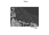
- Fig. 6 is a cross-section SEM observation image according to Example 3.
- Figs. 1 is a view schematically showing an exhaust gas purification device according to an embodiment.
- Fig. 2 is a perspective view schematically showing an exhaust gas purification filter according to the embodiment.
- Fig. 3 is a cross-sectional view
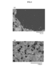
- FIG. 7(a) and 7(b) are SEM observation images according to Reference Example 1, Fig. 7(a) being a cross-section SEM observation image of a catalyst layer, Fig. 7(b) being a surface SEM observation image of the catalyst layer.
- Figs. 8(a) and 8(b) are SEM observation images according to Reference Example 2, Fig. 8(a) being a cross-section SEM observation image of a catalyst layer, Fig. 8(b) being a surface SEM observation image of the catalyst layer.
- Fig. 9 is a surface SEM observation image of a catalyst layer according to Reference Example 3. Figs.
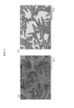
- FIGS. 10(a) to 10(c) are explanatory views for describing a method for calculating the ratio of pores from a cross-section SEM observation image of a catalyst layer
- Fig. 10(a) being a cross-section SEM observation image (at a magnification of 600 times) of the catalyst layer of Example 1 used for analysis
- Fig. 10(b) being an image showing the parts of pores after image processing
- Fig. 10(c) being an image showing the parts of large pores after the image processing.
- FIGs. 11(a) and 11(b) are explanatory views for describing a method for calculating a surface opening ratio from a surface SEM observation image of the framework of a catalyst layer
- Fig. 11(a) and 11(b) are explanatory views for describing a method for calculating a surface opening ratio from a surface SEM observation image of the framework of a catalyst layer
- Fig. 11(a) and 11(b) are explanatory views for describing a method for calculating
- FIG. 11(a) being a surface SEM observation image (at a magnification of 20,000 times) of the framework of the catalyst layer of Example 1 used for analysis
- Fig. 11(b) being an image showing the parts of surface openings after image processing.
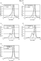
- Figs. 12(a) to 12(e) are pore distribution curves measured by a mercury porosimeter
- Fig. 12(a) showing an example in which the results of a base and Example 1 are compared with each other
- Fig. 12(b) showing an example in which the results of the base and Example 2 are compared with each other
- Fig. 12(c) showing an example in which the results of the base and Example 3 are compared with each other
- Fig. 12(d) showing an example in which the results of the base and Example 4 are compared with each other
- Fig. 12(e) showing an example in which the results of the base and Reference Example 1 are compared with each other.
- Fig. 13 is a graph showing the relationship between the length of the catalyst layer and a PM collection pressure loss.
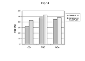
- Fig. 14 is a graph showing the measurement results of the 50% purification temperatures (T50) of Example 19 and Reference Example 6.
- Fig. 1 is a schematic view of the exhaust gas purification device 1 according to the embodiment.
- the exhaust gas purification device 1 is provided in the exhaust system of an internal combustion engine 2.
- a mixture containing oxygen and fuel gas is supplied to the internal combustion engine (engine) 2.
- the internal combustion engine 2 burns the mixture and converts burning energy into mechanical energy.
- the mixture burned at this time is exhausted to the exhaust system as exhaust gas.
- the internal combustion engine 2 having a configuration shown in Fig. 1 is configured mainly by the diesel engine of an automobile.
- the exhaust gas purification device 1 is, of course, applicable to an engine (such as a gasoline engine) other than a diesel engine.
- the exhaust gas purification device 1 has an exhaust path (including an exhaust manifold 3 and an exhaust pipe 4), an ECU 5, an exhaust temperature increasing catalyst 9 containing a carrier and a metal catalyst, and the exhaust gas purification filer (DPF) 10.
- the exhaust gas purification device 1 collects particulate matter (PM) contained in exhaust gas while purifying harmful substances (for example, carbon monoxide (CO), hydrocarbon (HC), and nitrogen oxide (NO x )) contained in the exhaust gas exhausted from the internal combustion engine 2.
- harmful substances for example, carbon monoxide (CO), hydrocarbon (HC), and nitrogen oxide (NO x )
- An exhaust port (not shown) that makes the internal combustion engine 2 and the exhaust system communicate with each other is connected to one end of the exhaust manifold 3.
- the other end of the exhaust manifold 3 is connected to the exhaust pipe 4.
- an arrow in the figure indicates the circulating direction of exhaust gas.
- the exhaust path for exhaust gas includes the exhaust manifold 3 and the exhaust pipe 4.
- the exhaust temperature increasing catalyst 9 and the exhaust gas purification filter 10 are arranged.
- the exhaust temperature increasing catalyst 9 is provided on the upstream side of the exhaust gas purification filter 10.
- the exhaust temperature increasing catalyst 9 has the function of increasing the temperature of exhaust gas flowing into the exhaust gas purification filter 10 during the regeneration of the exhaust gas purification filter 10.
- the exhaust temperature increasing catalyst 9 may be, for example, a known diesel oxidation catalyst (DOC), a three-way catalyst, a NO x occlusion reduction catalyst (LNT), or the like.
- the exhaust temperature increasing catalyst 9 may be, for example, a catalyst containing precious metal such as platinum (Pt), palladium (Pd), and rhodium (Rh).
- Pt platinum
- Pd palladium
- Rh rhodium
- the exhaust temperature increasing catalyst 9 is not necessarily provided and may be omitted where necessary. Note that since the configuration of the exhaust temperature increasing catalyst 9 does not characterize the present invention, its description will be omitted herein.
- the ECU 5 is an engine control unit that controls the internal combustion engine 2 and the exhaust gas purification device 1.
- the ECU 5 has a digital computer like, for example, a general control unit.
- the ECU 5 can have a central calculation processing unit (CPU: central processing unit) that executes the instruction of a control program, a ROM (read only memory) that stores the control program executed by the CPU, a RAM (random access memory) that is used as a working area in which the control program is to be developed, and a storage unit (recording medium) such as a memory that stores various data.
- CPU central calculation processing unit
- ROM read only memory
- RAM random access memory
- storage unit recording medium
- the ECU 5 is provided with an input port (not shown).
- the ECU 5 is electrically connected to sensors (for example, a pressure sensor 8) provided at the respective portions of the internal combustion engine 2 and the exhaust gas purification device 1.
- sensors for example, a pressure sensor 8
- the ECU 5 is provided with an output port (not shown).
- the ECU 5 transmits a control signal via the output port to control the internal combustion engine 2 and the exhaust gas purification device 1.
- the ECU 5 estimates to what extent PM is collected by the exhaust gas purification filter 10 (PM collection amount) based on a pressure loss value detected by the pressure sensor 8.
- PM collection amount the pressure loss value becomes a prescribed value or more
- the ECU 5 increases the temperature of the exhaust gas purification filter 10 to a prescribed temperature to burn and remove the PM. Since pressure loss hysteresis is kept small in the exhaust gas purification filter 10 disclosed herein, the PM collection amount can be precisely estimated based on the pressure loss value detected by the pressure sensor 8. Accordingly, the exhaust gas purification device 1 having the exhaust gas purification filter 10 is excellent in regeneration controllability. In addition, the exhaust gas purification device 1 can minimize the frequency of regeneration processing to improve fuel economy.
- Fig. 2 is a perspective view of the exhaust gas purification filter 10 according to the embodiment.
- Fig. 3 is a schematic view in which a part of a cross section obtained by cutting off the exhaust gas purification filter 10 according to the embodiment in a cylinder axis direction is enlarged. Note that in Figs. 2 and 3, an exhaust gas flowing direction is drawn by an arrow. That is, the left side and the right side of Figs. 2 and 3 are the upstream side and the downstream side of the exhaust path (the exhaust pipe 4), respectively.
- the exhaust gas purification filter 10 has the function of collecting particulate matter (PM) contained in exhaust gas and purifying the exhaust gas.
- the exhaust gas purification filter 10 of the embodiment has a base 11 having a wall flow structure and a porous catalyst layer 20 provided on the base 11. Hereinafter, the base 11 and the catalyst layer 20 will be described in this order.
- the base 11 constitutes the framework of the exhaust gas purification filter 10.
- any of bases having various materials and modes conventionally used as this type can be employed appropriately.
- a base made of a material having high heat-resistance properties as represented by ceramics such as cordierite, aluminum titanate, and silicon carbide (SiC) or an alloy such as stainless steel can be preferably employed.
- the base 11 can have an outer shape such as a cylindrical shape, an elliptic cylindrical shape, and a polygonal cylindrical shape. In Fig. 2, the base 11 having a cylindrical outer shape is employed as an example.
- the base 11 can have, for example, a shape such as a honeycomb shape, and a foam shape, a pellet shape. In the mode of Fig. 2, the base 11 having a honeycomb shape is employed as an example.
- the properties of the base 11 are not particularly limited.
- the base 11 has input-side cells 12 with their end on an exhaust-gas inflow side opened, output-side cells 14 with their end on an exhaust-gas outflow side opened, and a partition wall 16 that partitions the input-side cells 12 and the output-side cells 14.
- Sealing portions 12a are arranged at the ends of the input-side cells 12 on the exhaust-gas outflow side to seal the same.
- Sealing portions 14a are arranged at the ends of the output-side cells 14 on the exhaust-gas inflow side to seal the same.
- the input-side cells 12 and the output-side cells 14 can have a rectangular shape such as a square, a parallelogram, rectangle, and a trapezoid, a triangular shape, other polygonal shapes (for example, a hexagon and an octagon), or various geometric shapes such as a circular shape.
- the partition wall 16 that partitions the input-side cells 12 and the output-side cells 14 has a porous structure that allows exhaust gas to pass through.
- the average pore size of the partition wall 16 is not particularly limited, but may be substantially 5 to 30 ⁇ m, for example, 10 to 20 ⁇ m from the viewpoint of improving a PM collection function, suppressing an increase in pressure loss, or the like.
- the thickness of the partition wall 16 is not particularly limited, but may be substantially about 1 to 30 mil (1 mil is equivalent to about 25.4 ⁇ m) from the viewpoint of improving the PM collection function, suppressing an increase in pressure loss, or the like.
- the porosity of the partition wall 16 is not particularly limited, but may be substantially 20 to 70 vol%, for example 30 to 60 vol% from the viewpoint of improving the PM collection function, suppressing an increase in pressure loss, or the like.
- the catalyst layer 20 is provided on the wall surface of the partition wall 16.
- the catalyst layer 20 is provided on the wall surface of the partition wall 16 contacting the input-side cells 12.
- the catalyst layer 20 forms the core of the exhaust gas purification filter as a portion where PM in exhaust gas is to be collected.
- the catalyst layer 20 contains a carrier constituting the framework of the catalyst layer 20 and a metal catalyst (reactive catalyst) to excellently burn and remove collected PM.
- any of carriers having various materials and modes conventionally used as this type can be employed appropriately.
- a carrier made of a material having high heat-resistance properties such as alumina (Al 2 O 3 ), ceria (CeO 2 ), zirconia (ZrO 2 ), silica (SiO 2 ), and titania (TiO 2 ) can be preferably employed.
- the shape of the carrier may be a needle having a high aspect ratio. Note that the “needle” described in the present specification is a concept including a shape called, for example, a long rod shape, a wire shape, a scale shape, or the like.
- the average aspect ratio of particles constituting the carrier (a value obtained by dividing a length in the long axis direction of the particles by a length (typically a diameter) in the short axis direction thereof) may be substantially three or more, preferably five or more, and for example about ten to 50.
- the average length in the long axis direction of the particles constituting the carrier may be substantially 0.1 ⁇ m or more, preferably 0.5 ⁇ m or more, and for example 1 to 10 ⁇ m.
- the average length (typically a diameter) in the short axis direction of the particles constituting the carrier may be substantially 0.01 ⁇ m or more, preferably 0.05 ⁇ m or more, and for example 0.1 to 1 ⁇ m.
- the metal catalyst functions as an oxidation and/or a reduction catalyst.
- the metal catalyst any metal species capable of functioning as various oxidation catalysts or reduction catalysts can be employed appropriately.
- the metal catalyst include precious metal such as rhodium (Rh), palladium (Pd), and platinum (Pt) categorized as a platinum group.
- precious metal such as rhodium (Rh), palladium (Pd), and platinum (Pt) categorized as a platinum group.
- ruthenium (Ru), osmium (Os), iridium (Ir), silver (Ag), gold (Au), or the like may be used.
- the content of the metal catalyst is not particularly limited, but may be substantially 0.01 to 8 mass%, and for example about 0.1 to 5 mass% relative to, for example, the whole mass of the carrier of the catalyst layer 20.
- the catalyst layer 20 may appropriately contain any other components besides the carrier and the metal catalyst.
- examples of such components include various additives such as an OSC material (for example, a ceria-zirconia multiple oxide) having oxygen occlusion capacity, a NO x absorbing agent having NO x occlusion capacity, and a stabilizing material.
- the width (disposed area) of the catalyst layer 20 is not particularly limited.
- the catalyst layer 20 may be provided on, for example, the whole or only some parts of the wall surface of the partition wall 16. As an example, when the whole surface area of the partition wall 16 is 100%, the catalyst layer 20 may coat substantially 50% or more, for example 80% or more, and preferably 90% or more of the surface.
- the length of the catalyst layer 20 may be substantially 50% or more, typically 80% or more, preferably 90% or more, and, for example, the same as the whole length Lw in the extending direction of the partition wall 16.
- the PM collection function can be more excellently improved.
- PM hardly intrudes into pores inside the partition wall 16 of the base 11. Therefore, the pressure loss hysteresis can be remarkably kept small with the collection of the PM in the pores inside the partition wall 16 suppressed.
- the catalyst layer 20 may be provided on the wall surface of the partition wall 16 sequentially or intermittently.
- the length of the catalyst layer 20 can be adjusted with the input amount of slurry in, for example, a manufacturing method that will be described later.
- the average thickness (the length crossing the extending direction of the partition wall 16) of the catalyst layer 20 is not particularly limited, but may be substantially 1 to 300 ⁇ m, typically 5 to 100 ⁇ m, and for example about 10 to 50 ⁇ m from the viewpoint of exhibiting the effect of the invention of the present application at high level and more excellently exhibiting the PM collection function.
- the coating amount of the catalyst layer 20 per 1 L of the base is not particularly limited, but may be substantially 100 g/L or less, preferably 50 g/L or less, and for example 30 g/L or less from the viewpoint of reducing a pressure loss at higher level.
- the catalyst layer 20 has structural properties in which the porosity is high and the gas permeability is excellent.
- the porosity Va of the catalyst layer 20 i.e., the ratio of the pores occupied in the catalyst layer 20
- the porosity Va of the catalyst layer 20 may be substantially 60% or more, preferably 70% or more, substantially 90% or less, typically 85% or less, and for example 80% or less. With the porosity Va set at a prescribed value or more, the gas permeability of the catalyst layer 20 becomes more excellent and the pressure loss hysteresis can be more excellently reduced.
- the catalyst layer 20 burning activity can be improved with an increase in the contact points between PM and the metal catalyst, and NO 2 generated when NO in exhaust gas is oxidized is allowed to easily reach the PM with an improvement in the proximity between the PM and the metal catalyst. Therefore, PM burning quality at low temperature can be increased, and the regeneration ratio of the exhaust gas purification filter 10 can be improved.
- the porosity Va set at the prescribed value or less, the mechanical strength of the catalyst layer 20 can be improved.
- the porosity Va can be adjusted with the control of the ratio of mixing a carrier and a pore shaping agent together in slurry or the size (the particle size) of the carrier and/or the pore shaping agent in, for example, the manufacturing method that will be described later.
- the porosity Va of the catalyst layer 20 can be calculated as follows. (1) First, a sample piece containing the catalyst layer 20 is embedded with a resin, and the cross section of the catalyst layer 20 is cut out. (2) Next, the cut-out cross section of the sample piece is observed with a scanning electron microscope (SEM) to obtain a cross-section SEM observation image (a reflection electron image obtained at an observation magnification of 600 times). Note that a field of view for the observation is set so as to include substantially 20 or more, for example 50 or more of the pores defined by the framework of the catalyst layer 20 to obtain the cross-section SEM observation image.
- SEM scanning electron microscope
- a processing range is set to the catalyst layer 20 using two-dimensional image analysis software, i.e., winroof (registered trademark), and the occupied portion of the pores is extracted by automatic binarization (discriminant analysis method) to obtain a binary image.
- expansion processing and contraction processing are each applied to the binary image twice.
- the respective pores are separated so as to have a circular shape by circular separation measurement (automatic processing).
- the ratio (area%) of the occupied area of the pores when the area of the catalyst layer is 100% in the analyzed image is measured to calculate the porosity Va.
- the porosity Vb of large pores calculated based on the electron microscope observation may be substantially 45% or more, for example 50% or more, the porosity Va or less, substantially 85% or less, typically 80% or less, and for example 70% or less.
- the porosity Vb of the large pores set at a prescribed value or more gas permeability is improved.
- an increase in pressure loss associated with the formation of the catalyst layer 20 is reduced, and PM burning quality can be improved.
- the porosity Vb set at a prescribed value or less the mechanical strength of the catalyst layer 20 can be improved.
- the porosity Vb can be adjusted with the control of the ratio of mixing the carrier and the pore shaping agent together in the slurry or the size (the particle size) of the carrier and/or the pore shaping agent in, for example, the manufacturing method that will be described later.
- the porosity Vb of the large pores of the catalyst layer 20 can be calculated in such a manner as to measure the ratio (area%) of the occupied area of the pores after subtracting the portions of the pores having a circle equivalent diameter of 5 ⁇ m or less from the whole porosity (the porosity calculated in the step (6)) Va of the catalyst layer 20.
- the ratio of the porosity Vb of the large pores to the porosity Va may be substantially 60% or more, preferably 70% or more, substantially 99% or less, typically 98% or less, for example 90% or less, and 80% or less as an example.
- Vb/Va the ratio of the porosity Vb of the large pores to the porosity Va
- the catalyst layer 20 typically has first pores defined by the framework and second pores formed inside the framework and communicating with the first pores.
- the catalyst layer 20 has a multiple pore structure (for example, a binary pore structure) and is configured to be capable of collecting PM even with the framework.
- the average pore sizes of the first pores and the second pores are typically less than or equal to the average pore size of the pores formed inside the partition wall 16 of the base 11, and preferably smaller than the average pore size of the pores formed inside the partition wall 16 of the base 11.
- the relationship between the sizes of the average pores satisfies the relationship the second pores ⁇ the first pores ⁇ the pores of the partition wall 16 of the base 11.
- the mechanical strength or durability of the framework can be improved when the pore size of the second pores is relatively reduced.
- the catalyst layer 20 has a configuration having multistage pore sizes (for example, two-stage pore sizes), a more excellent PM collection function can be exhibited. As a result, with the suppression of the collection of PM in the pores inside the partition wall, pressure loss hysteresis can be more excellently suppressed.
- the catalyst layer 20 has the first pores defined by the framework and is configured to have a three-dimensional mesh shape. Any cross section of the catalyst layer 20 can have a plurality of divided portions when the framework is divided. It appears that the larger the number of divided portions (the number of divisions), the higher the communication of the pores is. That is, the number of divisions can be an indicator showing the communication of the pores inside the catalyst layer 20.
- the number of divisions per unit cross-sectional area (0.01 mm 2 ) may be substantially ten or more, typically 20 or more, preferably 30 or more, more preferably 50 or more, for example 60 or more, and 80 or more as an example from the viewpoint of improving gas permeability. From the viewpoint of improving mechanical strength, the number of divisions per unit cross-sectional area may be substantially 200 or less, preferably 180 or less, and for example 120 or less.
- the number of divisions per unit cross-sectional area of the framework can be calculated as follows. (1) First, a sample piece containing the catalyst layer 20 is embedded with a resin, and the cross section of the catalyst layer 20 is cut out. (2) Next, the cut-out cross section of the sample piece is observed with a scanning electron microscope (SEM) to obtain a cross-section SEM observation image (a reflection electron image obtained at an observation magnification of 600 times). (3) Then, a processing range is set to the catalyst layer 20 using two-dimensional image analysis software, i.e., winroof (registered trademark), and a framework is extracted by automatic binarization (discriminant analysis method) to obtain a binary image.
- SEM scanning electron microscope
- the framework may have an average thickness of substantially 5 ⁇ m or less, typically 4 ⁇ m or less, preferably 3.5 ⁇ m or less, and for example 3 ⁇ m or less.
- the lower limit of the average thickness is not particularly limited, but may be substantially 0.5 ⁇ m or more, typically 1 ⁇ m or more, and for example 1.5 ⁇ m or more from the viewpoint of improving mechanical strength.
- the average thickness of the framework is calculated in such a manner as to perform the same procedures (1) to (4) as those of the calculation of the number of divisions and then calculate the lengths of the shortest areas (the minimum lengths passing through the gravity) of respective divided portions to take an arithmetic mean of the values.
- the framework may have a surface opening ratio of substantially 20% or more, typically 25% or more, preferably 30% or more, substantially 60% or less, typically 55% or less, and for example 50% or less.
- a surface opening ratio of substantially 20% or more, typically 25% or more, preferably 30% or more, substantially 60% or less, typically 55% or less, and for example 50% or less.
- the surface opening ratio of the framework of the catalyst layer 20 can be calculated as follows. (1) First, a sample piece containing the catalyst layer 20 is fixed onto the surface of a sample table so that the extending direction of the base 11 and the surface of the sample table become parallel to each other. (2) Next, the surface of the sample piece is observed with a field emission scanning electron microscope (FE-SEM) to obtain a surface SEM observation image (a secondary electron image obtained at an observation magnification of 20,000 times) from the outermost surface side of the catalyst layer 20. (3) Then, surface openings are extracted by automatic binarization (discriminant analysis method) using two-dimensional image analysis software, i.e., winroof (registered trademark) to obtain a binary image.
- FE-SEM field emission scanning electron microscope
- the average pore size of the second pores formed inside the framework of the catalyst layer 20 is typically smaller than the average pore size of the first pores and smaller than, for example, 5 ⁇ m.
- a pore size P5 corresponding to a cumulative 5% pore size from the small pore side of pore sizes may be for example 0.01 ⁇ m or more, preferably 0.02 ⁇ m or more, typically 0.03 ⁇ m or more, for example 0.035 ⁇ m or more, substantially 0.1 ⁇ m or less, typically 0.05 ⁇ m or less, and for example 0.04 ⁇ m or less.
- a pore size P95 corresponding to a cumulative 95% pore size from the small pore side of the small pores may be substantially 1 ⁇ m or more, typically 1.5 ⁇ m or more, for example 2 ⁇ m or more, for example 5 ⁇ m or less, preferably 4 ⁇ m or less, typically 3.5 ⁇ m or less, and for example 3 ⁇ m or less.
- both the pore size P5 and the pore size P95 may be 0.01 to 5 ⁇ m and preferably 0.02 to 4 ⁇ m.
- the average pore size of the second pores is calculated in such a manner as to perform the same procedures (1) to (4) as those of the calculation of the surface opening ratio and then perform shape characteristic measurement on the analyzed image to measure a circle equivalent diameter.
- the catalyst layer 20 contains the pores equivalent to or smaller in size than the pores formed inside the partition wall 16 of the base 11.
- a typical example shows that the catalyst layer 20 has two pore peaks in a pore size of 0.5 to 10 ⁇ m in a differential pore distribution curve obtained by the measurement of a mercury porosimeter.
- the catalyst layer 20 can have a peak A in a range in which a pore size is 1 ⁇ m or more and 10 ⁇ m or less and have a peak B in a range in which the pore size is 0.5 ⁇ m or more and 1 ⁇ m or less.
- Each of the two peaks A and B can indicate the first pores defined by the framework of the catalyst layer 20 and the second pores formed inside the framework and communicating with the first pores.
- the pore volume (V1) of the peak A derived from the first pores can be different depending on the type of the base 11 or the like, but may be substantially 0.03 cm 3 /g or more, preferably 0.04 cm 3 /g or more, and more preferably 0.05 cm 3 /g or more.
- the pore volume V1 may be substantially 0.1 cm 3 /g or less and for example 0.08 cm 3 /g or less from the viewpoint of improving mechanical strength.
- the pore volume (V2) of the peak B derived from the second pores can be different depending on the type of the base 11 or the like, but is smaller than that of the peak A.
- the pore volume V2 may be substantially 0.001 cm 3 /g or more and preferably 0.002 cm 3 /g or more from the viewpoint of exhibiting the effect of the present invention at high level.
- the pore volume V2 may be substantially 0.02 cm 3 /g or less and for example 0.015 cm 3 /g or less from the viewpoint of ensuring the pore volume V1 or improving mechanical strength.
- the ratio of the pore volume of the first pores to that of the second pores may be substantially three or more, preferably four or more, more preferably five or more, and for example six or more.
- the upper limit of the ratio is not particularly limited, but may be substantially 30 or less, preferably 20 or less, and for example ten or less from the viewpoint of improving mechanical strength.
- the pore distribution of the catalyst layer 20 can be calculated as follows. First, the sample piece of the base 11 having the catalyst layer 20 is prepared, and the pore distribution of the sample piece is measured in a range of 1 to 60,000 psi using a commercially available mercury porosimeter. Thus, a pore distribution curve showing the relationship between a pore size and a pore volume is obtained. The obtained pore distribution curve is compared with a pore distribution curve based on only the base to confirm the state of the pores formed inside the catalyst layer 20. In addition, the pore volumes of the respective peaks can be calculated from the obtained pore distribution curve.
- a pore volume (cm 3 /g) per unit mass of the catalyst layer 20 can be calculated in such a manner as to calculate the cumulative pore volumes (cm 3 /g) of the respective peaks of the sample piece containing the catalyst layer 20 from the cumulative pore volume distribution curve and subtract the pore volume of only the base 11 in the same range.
- exhaust gas exhausted from the internal combustion engine 2 flows from the end of the base 11 on the exhaust-gas inflow side into the input-side cells 12 of the exhaust gas purification filter 10.
- the exhaust gas flowing into the input-side cells 12 reaches the output-side cells 14 after passing through the catalyst layer 20 having the porous structure and the partition wall 16. PM in the exhaust gas is collected by the surface of and/or inside the catalyst layer 20 while the exhaust gas passes through the catalyst layer 20.
- the exhaust gas reaching the output-side cells 14 flows out from the ends of the output-side cells on the exhaust-gas outflow side to the outside of the exhaust gas purification filter 10.
- the catalyst layer 20 has large pores at a relatively high ratio compared with a conventional catalyst layer.
- the gas permeability is improved with the arrangement of the catalyst layer 20, whereby an increase in pressure loss associated with the catalyst layer 20 can be suppressed.
- PM burning quality at a low temperature can be improved due to the proximity between PM and the metal catalyst in the catalyst layer 20.
- harmful substances other than PM in exhaust gas can be simultaneously purified (rendered harmless) while the exhaust gas passes through the catalyst layer 20.
- an HC component or a CO component contained in exhaust gas can be oxidized by the metal catalyst to be converted (purified) into water (H 2 O), carbon dioxide (CO 2 ), or the like.
- a NO x component can be reduced by the metal catalyst to be converted (purified) into nitrogen (N 2 ).
- the catalyst layer 20 according to the embodiment has the multiple pore structure (for example, the binary pore structure) containing the first pores and the second pores, and the framework of the catalyst layer has the PM collection function. Accordingly, the excellent PM collection function can be exhibited. Furthermore, the collection of PM in the pores inside the partition wall 16 is suppressed since the catalyst layer 20 has the multiple pore structure. Accordingly, pressure loss hysteresis can be suppressed.
- the exhaust gas purification filter 10 configured as described above can be manufactured in the following manner. First, a solution containing salt (for example, nitrate salt) or a complex (for example, tetraammine complex) including a desired metal catalyst species is prepared. The solution is dried and burned after being impregnated with desired carrier powder. Thus, metal-catalyst carrying carrier powder in which the carrier powder carries the metal catalyst can be obtained. Next, at least the metal-catalyst carrying carrier powder, a pore shaping agent, and an appropriate solvent (for example, ion exchange water) are mixed together at a prescribed ratio to prepare catalyst layer forming slurry.
- salt for example, nitrate salt
- a complex for example, tetraammine complex
- a desired base 11 is provided. After being applied onto the base 11, the slurry is dried and burned. According to a wet process method, a homogeneous catalyst layer 20 can be preferably formed. Thus, the catalyst layer 20 is formed, and the exhaust gas purification filter 10 can be obtained.
- the pore shaping agent may be one capable of being removed by thermal decomposition at burning.
- the pore shaping agent include starch, carbon powder, active carbon, high polymer organic material (for example, polyethylene, polypropylene, melamine resin, and polymethyl methacrylate (PMMA) resin), or the like.
- the pore shaping agent may have an average particle size of substantially 2 ⁇ m or more, preferably 5 ⁇ m or more, and for example about 5 to 20 ⁇ m.
- the slurry can contain any other additive components besides the metal-catalyst carrying carrier powder, the pore shaping agent, and the solvent.
- the mixing ratio between the carrier powder and the shaping agent can be one significant factor from the viewpoint of realizing the catalyst layer 20.
- the mixing ratio between the carrier powder and the pore shaping agent can be different depending on, for example, the properties (for example, the aspect ratio or the length in the long axis direction) of the carrier powder or the like, but may be adjusted so that the volume of the pore shaping agent becomes substantially three times or more, substantially 15 times or less, and for example ten times or less of the volume of the carrier powder.
- the catalyst layer 20 excellent in gas permeability can be more excellently realized.
- the ratio of an increase in pressure loss with the formation of the catalyst layer 20 can be kept at 1.6 times or less of that obtained when only the base 11 is provided.
- the viscosity of the slurry can also be one significant factor from the viewpoint of realizing the catalyst layer 20.
- the slurry may be adjusted to have a viscosity of substantially 30 mPa-s or more, preferably 50 mPa-s or more, and substantially 500 mPa-s or less when a measurement temperature is 25°C and a shearing speed is 300 to 500 s -1 .
- the viscosity of the slurry can be measured by a commercially available viscosity meter (for example, a dynamic visco-elastic measurement device).
- the catalyst layer 20 can be preferably formed on the surface of the base using the slurry having such a viscosity.
- a thickening agent for the adjustment of the viscosity of the slurry, various additives such as a thickening agent, a surfactant, and a dispersing agent can be, for example, used.
- a thickening agent include cellulosic polymer such as hydroxyethyl cellulose (HEC), methyl cellulose (MC), carboxymethyl cellulose (CMC), hydroxypropyl methyl cellulose (HPMC), and hydroxyethyl methyl cellulose (HEMC).
- the surfactant include a non-ionic surfactant.
- conditions for drying and burning the slurry are not particularly limited, but the slurry may be, for example, dried for about one to ten hours at about 80 to 300°C and then burned for about two to four hours at about 400 to 1000°C.
- the exhaust gas purification filter disclosed herein may have a second catalyst layer besides the porous catalyst layer.
- the second catalyst layer is formed inside the partition wall of the base.
- the exhaust gas filter disclosed herein can preferably collect PM with the porous catalyst layer formed on the base.
- the PM is prevented from intruding into the second catalyst layer formed inside the partition wall, and the inhibition of the catalytic action of the second catalyst layer by the PM can be suppressed.
- catalytic metal contained in a porous catalyst layer formed on the upper layer of the second catalyst layer can be caused to secondarily function. Therefore, the second catalyst layer can exhibit high exhaust gas purification capacity.
- a three-way catalyst As a metal catalyst contained in the second catalyst layer, a three-way catalyst, a diesel oxidation catalyst, a NO x occlusion reduction catalyst, an SCR catalyst, or the like can be preferably used.
- a three-way catalyst catalytic metal that oxidizes CO and HC and reduces NO x
- a platinoid element such as platinum (Pt), palladium (Pd), rhodium (Rh), ruthenium (Ru), osmium (Os), and iridium (Ir), silver (Ag), gold (Au), or the like is used.
- platinum palladium
- Rh rhodium
- Ru ruthenium
- Ir osmium
- Ir iridium
- silver Au
- Au gold
- any of platinum and palladium can be preferably used.
- a catalyst that contains platinum, palladium, and rhodium as catalytic metal and contains rare earth such as Ce, alkali earth metal such as Ba and K, and alkali metal as a NO x occlusion material can be preferably used.
- an SCR catalyst for example, transition metal ion-exchanged zeolite carrying transition metal (such as Cu and Fe)
- transition metal such as Cu and Fe
- an SCR catalyst for example alumina carrying Ag
- reduces NO x with HC as a reducing agent or the like
- Example 1 Formation of Catalyst Layers>> (Example 1) First, a honeycomb base (made of SiC, having a cell number of 300 cpsi, and having a partition wall thickness of 12 mil) manufactured by NGK Insulators, Ltd. was prepared as a base. Next, a solution in which a dinitrodiammine platinum nitric acid solution and a palladium nitrate solution were mixed together was impregnated with needle Al 2 O 3 powder (having an average fiber diameter ⁇ of 0.5 ⁇ m and an average fiber length L of 6 ⁇ m) serving as a carrier and then dried and burned to obtain Pt/Pd-carrying Al 2 O 3 powder serving as a carrier.
- needle Al 2 O 3 powder having an average fiber diameter ⁇ of 0.5 ⁇ m and an average fiber length L of 6 ⁇ m
- the obtained Pt/Pd-carrying Al 2 O 3 powder, an Al 2 O 3 sol (having an Al 2 O 3 content of 7%) serving as a binder, and pure water serving as a solvent were mixed together at a mass ratio (g) of 200:1000:400 and subjected to wet milling to prepare slurry.
- Melamine resin beads having an average particle size of 5 ⁇ m
- a surfactant RHEODOL 430V (manufactured by Kao Corporation)
- CMC carboxymethyl cellulose
- the catalyst layer forming slurry was input from the end of the base on the exhaust-gas inflow side into input-side cells and then suctioned from the end thereof on the exhaust-gas outflow side, whereby the slurry was applied onto the wall surface of the partition wall on the exhaust-gas inflow side over a longitudinal 100% region in the extending direction of the partition wall according to an input method.
- the slurry was dried at 150°C and then burned at 500°C to burn out the component of the pore shaping agent and form a catalyst layer on the surface of the partition wall (atop the partition wall) on the exhaust-gas inflow side. Note that the coating amount of the slurry was adjusted so that the formed catalyst layer became 15 g/L per base capacity.
- Example 2 Except for using melamine resin beads (having an average particle size of 10 ⁇ m) as a pore shaping agent, a catalyst layer was formed on the surface of the partition wall on the exhaust-gas inflow side in the same manner as Example 1.
- Example 3 First, a honeycomb base (made of SiC, having a cell number of 300 cpsi, and having a partition wall thickness of 12 mil) manufactured by NGK Insulators, Ltd. was prepared as a base. Next, a solution in which a dinitrodiammine platinum nitric acid solution and a palladium nitrate solution were mixed together was impregnated with needle TiO 2 powder (having an average fiber diameter ⁇ of 0.2 ⁇ m and an average fiber length L of 3 ⁇ m) serving as a carrier and then dried and burned to obtain Pt/Pd-carrying TiO 2 powder serving as a carrier.
- needle TiO 2 powder having an average fiber diameter ⁇ of 0.2 ⁇ m and an average fiber length L of 3 ⁇ m
- the obtained Pt/Pd-carrying TiO 2 powder, a TiO 2 sol (having a TiO 2 content of 6%) serving as a binder, and pure water serving as a solvent were mixed together at a mass ratio (g) of 200:1200:200 and subjected to wet milling to prepare slurry.
- Melamine resin beads having an average particle size of 2 ⁇ m
- a surfactant RHEODOL 430V (manufactured by Kao Corporation)
- CMC carboxymethyl cellulose
- the catalyst layer forming slurry was input from the end of the base on the exhaust-gas inflow side into the input-side cells and then suctioned from the end thereof on the exhaust-gas outflow side, whereby the slurry was applied onto the wall surface of the partition wall on the exhaust-gas inflow side over a longitudinal 100% region in the extending direction of the partition wall according to an input method.
- the slurry was dried at 150°C and then burned at 500°C to burn out the component of the pore shaping agent and form a catalyst layer on the surface of the partition wall on the exhaust-gas inflow side. Note that the coating amount of the slurry was adjusted so that the formed catalyst layer became 20 g/L per base capacity.
- Example 4 Except for using melamine resin beads (having an average particle size of 5 ⁇ m) as a pore shaping agent, a catalyst layer was formed on the surface of the partition wall on the exhaust-gas inflow side in the same manner as Example 3.
- Example 5 Except for using melamine resin beads (having an average particle size of 10 ⁇ m) as a pore shaping agent, a catalyst layer was formed on the surface of the partition wall on the exhaust-gas inflow side in the same manner as Example 3.
- Example 6 Except for using needle TiO 2 powder (having an average fiber diameter ⁇ of 0.3 ⁇ m and an average fiber length L of 5 ⁇ m) as a carrier, a catalyst layer was formed on the surface of the partition wall on the exhaust-gas inflow side in the same manner as Example 5.
- Example 7 Except for using particulate Al 2 O 3 powder (milled so as to have an average particle size of 2 ⁇ m by wet milling) as a carrier, a catalyst layer was formed on the surface of the partition wall on the exhaust-gas inflow side in the same manner as Example 1.
- Example 8 Except for using particulate TiO 2 powder (milled so as to have an average particle size of 2 ⁇ m by wet milling) as a carrier, a catalyst layer was formed on the surface of the partition wall on the exhaust-gas inflow side in the same manner as Example 4.
- Example 9 First, a honeycomb base (made of SiC, having a cell number of 300 cpsi, and having a partition wall thickness of 12 mil) manufactured by NGK Insulators, Ltd. was prepared as a base. Next, a solution in which a dinitrodiammine platinum nitric acid solution and a palladium nitrate solution were mixed together was impregnated with particulate CeZr powder (milled so as to have an average particle size of 2 ⁇ m by wet milling) serving as a carrier and then dried and burned to obtain Pt/Pd-carrying CeZr powder serving as a carrier.
- particulate CeZr powder milled so as to have an average particle size of 2 ⁇ m by wet milling
- the obtained Pt/Pd-carrying CeZr powder, a ZrO 2 sol (having a ZrO 2 content of 30%) serving as a binder, and pure water serving as a solvent were mixed together at a mass ratio (g) of 200:240:1160 and subjected to wet milling to prepare slurry.
- Melamine resin beads having an average particle size of 5 ⁇ m
- a surfactant RHEODOL 430V (manufactured by Kao Corporation)
- CMC carboxymethyl cellulose
- the catalyst layer forming slurry was input from the end of the base on the exhaust-gas inflow side into the input-side cells and then suctioned from the end thereof on the exhaust-gas outflow side, whereby the slurry was applied onto the wall surface of the partition wall on the exhaust-gas inflow side over a longitudinal 100% region in the extending direction of the partition wall according to an input method.
- the slurry was dried at 150°C and then burned at 500°C to burn out the component of the pore shaping agent and form a catalyst layer on the surface of the partition wall on the exhaust-gas inflow side. Note that the coating amount of the slurry was adjusted so that the formed catalyst layer became 20 g/L per base capacity.
- Example 10 Except for using melamine resin beads (having an average particle size of 10 ⁇ m) as a pore shaping agent, a catalyst layer was formed on the surface of the partition wall on the exhaust-gas inflow side in the same manner as Example 9.
- Example 11 Except for using starch (having an average particle size of 2 ⁇ m) as a pore shaping agent, a catalyst layer was formed on the surface of the partition wall on the exhaust-gas inflow side in the same manner as Example 1.
- Example 12 Except for using starch (having an average particle size of 5 ⁇ m) as a pore shaping agent, a catalyst layer was formed on the surface of the partition wall on the exhaust-gas inflow side in the same manner as Example 1.
- Example 13 Except for using starch (having an average particle size of 10 ⁇ m) as a pore shaping agent, a catalyst layer was formed on the surface of the partition wall on the exhaust-gas inflow side in the same manner as Example 1.
- Example 14 Except for using polymethyl methacrylate (PMMA) resin (having an average particle size of 2 ⁇ m) as a pore shaping agent, a catalyst layer was formed on the surface of the partition wall on the exhaust-gas inflow side in the same manner as Example 1.
- PMMA polymethyl methacrylate
- Example 15 Except for using a polymethyl methacrylate (PMMA) resin (having an average particle size of 5 ⁇ m) as a pore shaping agent, a catalyst layer was formed on the surface of the partition wall on the exhaust-gas inflow side in the same manner as Example 1.
- PMMA polymethyl methacrylate
- Example 16 Except for using a polymethyl methacrylate (PMMA) resin (having an average particle size of 10 ⁇ m) as a pore shaping agent, a catalyst layer was formed on the surface of the partition wall on the exhaust-gas inflow side in the same manner as Example 1.
- PMMA polymethyl methacrylate
- Figs. 4(a) to 4(d) are SEM observation images according to Example 1.
- Fig. 4(a) is a cross-section SEM observation image (at a magnification of 500 times) of the catalyst layer
- Fig. 4(b) is a cross-section SEM observation image (at a magnification of 2000 times) of the catalyst layer.
- Fig. 4(a) is a cross-section SEM observation image (at a magnification of 500 times) of the catalyst layer
- Fig. 4(b) is a cross-section SEM observation image (at a magnification of 2000 times) of the catalyst layer.
- Fig. 4(a) is a cross-section SEM observation image (at a magnification of 2000 times) of the catalyst layer.
- Fig. 4(a) is a cross-section SEM observation image (at a magnification of 2000 times) of the catalyst layer.
- Fig. 4(c) is a surface SEM observation image (at a magnification of 500 times) of the catalyst layer
- Fig. 4(d) is a surface SEM observation image (at a magnification of 2000 times) of the catalyst layer
- Fig. 5 is a cross-section SEM observation image (at a magnification of 600 times) of the catalyst layer according to Example 2.
- Fig. 6 is a cross-section SEM observation image (at a magnification of 600 times) of the catalyst layer according to Example 3.
- Figs. 7(a) and 7(b) are SEM observation images according to Reference Example 1, Fig. 7(a) being a cross-section SEM observation image (at a magnification of 600 times) of the catalyst layer, Fig.
- Figs. 8(a) and 8(b) are SEM observation images according to Reference Example 2. Specifically, Fig. 8(a) is a cross-section SEM observation image (at a magnification of 600 times) of the catalyst layer, and Fig. 8(b) is a surface SEM observation image (at a magnification of 500 times) of the catalyst layer. Fig. 9 is a surface SEM observation image (at a magnification of 500 times) of the catalyst layer according to Reference Example 3.
- the binary pore structure was formed by the two types of pores in Examples 1 to 16. That is, the catalyst layers in Examples 1 to 16 had the relatively large first pores defined by the frameworks of the catalyst layers and the relatively small second pores formed inside the frameworks. In addition, the specific observation of the second pores reveals that needle materials used as carriers were connected to each other to form networks, whereby pores (having a size less than 1 ⁇ m) smaller than the first pores were distributed in the frameworks of the catalyst layers as shown in Figs. 4(a) to 4(d), or the like. On the other hand, as shown in Fig. 7(a), the formation of a clear binary pore structure was not confirmed in the catalyst layer in Reference Example 1.
- the catalyst layers had a high porosity Va of 70% or more (for example, about 70 to 85%) in Examples 1 to 16.
- porosities Vb of the large pores (the pores having a circle equivalent diameter greater than 5 ⁇ m) occupied 45% or more (for example, about 45 to 85%) of the whole catalyst layers.
- the ratios of Vb to Va (Vb/Va) were 60% or more (for example, 60 to 98%) in Examples 1 to 16.
- the catalyst layer had a porosity Va of about 23% only in Reference Example 1.
- an occupied ratio Vb of the large pores (pores having a circle equivalent diameter greater than 5 ⁇ m) was less than 1% of the whole catalyst layer in Reference Example 1. Note that measurements were not allowed in Reference Examples 2 to 5 since only the parts of the catalyst layers could not be extracted due to the formation of the catalyst layers inside the partition walls.
- the catalyst layers have the binary pore structure, and the pores dispersed in the catalyst layers are connected to each other in Examples 1 to 16. Therefore, as shown in Table 1, the frameworks were divided at any cross section, and the number of divisions was large, i.e., about 30 to 180 per 0.01 mm 2 in Examples 1 to 16. In addition, the average thicknesses of the frameworks were also kept at 4 ⁇ m or less (for example, about 1 to 4 ⁇ m) in Examples 1 to 16. On the other hand, the framework had almost no divided parts in Reference Example 1 in which the binary pore structure was not confirmed, and thus the number of divisions was less than 2. In addition, the framework had an overwhelmingly large average thickness of 30 ⁇ m or more in Reference Example 1. Note that measurements were not allowed in Reference Examples 2 to 5 since the catalyst layers were formed inside the partition walls.
- the frameworks had a high surface opening ratio of about 25 to 55% in Examples 1 to 16. In addition, the frameworks had a pore size of about 0.02 to 4 ⁇ m. Note that measurements were not allowed in Reference Examples 2 and 4.
- Fig. 12(a) shows an example in which the results of the base and Example 1 are compared with each other
- Fig. 12(b) shows an example in which the results of the base and Example 2 are compared with each other
- Fig. 12(c) shows an example in which the results of the base and Example 3 are compared with each other
- FIG. 12(d) shows an example in which the results of the base and Example 4 are compared with each other
- Fig. 12(e) shows an example in which the results of the base and Reference Example 1 are compared with each other.
- a large peak was observed when the pore size was in the range of 1 ⁇ m or more and less than 10 ⁇ m
- a pore volume obtained when the pore size was in the range of 1 ⁇ m or more and less than 10 ⁇ m was increased compared with that of the base.
- the increased pore volume is derived from the first pores defined by the frameworks of the catalyst layers.
- Example 1 shown in Fig. 12(a) a broad peak was observed when the pore size was in the range of 0.5 ⁇ m or more and less than 1 ⁇ m. From a study with the SEM observation image, it appears that the peak is derived from the second pores formed when the needle materials are connected to each other inside the framework of the catalyst layer to form a network. On the other hand, as shown in Fig. 12(e), a clear peak was not confirmed even with analysis software when the pore size was in the range of 1 ⁇ m or more and less than 10 ⁇ m in Reference Example 1.
- the pore volumes of the catalyst layers were calculated from differences with the pore volume of the base.
- differences in pore volume when the pore size was in the range of 1 ⁇ m or more and less than 10 ⁇ m were described as “pore volumes V1 of first pore peaks,” and differences in pore volume between the pore volumes when the pore size was in the range of 0.5 ⁇ m or more and less than 1 ⁇ m were described as “pore volumes V2 of second pore peaks.” Results are shown in Table 1.
- the pore volumes V1 of the first pore peaks were relatively large and the ratios of the pore volumes V1 of the first pore peaks to the pore volumes V2 of the second pore peaks (V1/V2) were also large, i.e., four or more (for example, four to 20) in Examples 1 to 16.
- V1/V2 was less than four in Reference Examples 1 to 5.
- PM Collection Pressure losses >> About the manufactured exhaust gas purification filter, PM collection pressure losses (kPa/(g/sec)) were measured. Specifically, PM was collected with the exhaust gas purification filter installed in an engine bench, and pressure losses at a point at which the PM was collected by 5 g were evaluated. The pressure losses were standardized with an intake air amount. Results are shown in Table 1.
- the exhaust gas purification filter had a low PM collection pressure loss of 0.1 kPa/(g/sec) or less in Examples 1 to 16. It appears that this is because the collection of PM was suppressed inside the pores of the base with the catalyst layer functioning as filtration layers, which resulted in the suppression of a rapid increase in the pressure losses at initial PM collection.
- the PM collection pressure losses were higher than 0.1 kPa/(g/sec) in Reference Examples 1 to 5. It appears that this is because a rapid increase in the pressure loss at initial PM collection was reduced with the arrangement of the catalyst layer on the partition wall of the cells but the PM collection pressure loss became high since an original product pressure loss was high in Reference Example 1.
- pressure loss hysteresis was evaluated by a bench test. Specifically, with the exhaust gas purification filter installed in an engine bench, an initial collection pressure loss obtained when the collection of PM was started from a state before the use (before the collection of the PM) and a post-regeneration collection pressure loss obtained when the collection of the PM was started again from a state in which the PM remained by 5 g after regeneration processing were measured. Then, the values of the initial collection pressure loss and the post-regeneration collection pressure loss were compared with each other, and a difference in PM collection amount when the values of the pressure losses were the same was regarded as pressure loss hysteresis (g/unit). Rresults are shown in Table 1.
- the catalyst layers had low pressure loss hysteresis of 2.5 (g/unit) or less in Examples 1 to 16. It appears that this is because the catalyst layers functioned as filtration layers to suppress the collection of PM inside the pores of the base. In addition, since the catalyst layers had low pressure loss hysteresis of 1.4 (g/unit) but had a higher absolute value of the PM collection pressure loss compared with Examples 1 to 16 in Reference Example 1, fuel economy was assumed to become poor. On the other hand, the catalyst layers had high pressure loss hysteresis of 5 (g/unit) or more in Reference Examples 2 to 5.
- PM collection performance was evaluated by a vehicle test. Specifically, with the exhaust gas purification filter installed on the exhaust path of a vehicle, the number of exhausted PM particles (particle number/km) obtained when the vehicle traveled under an NEDC mode was evaluated. Results are shown in Table 1.
- the exhaust gas purification filter exhausted a relatively small number of exhausted PM particles compared with Reference Examples 2 to 5 and was excellent in the PM collection performance. It appears that this is because the catalyst layers arranged on the partition wall of the cells functioned as filtration layers to exhibit high PM collection efficiency. In addition, the exhaust gas purification filter having the catalyst layer on the partition wall in Reference Example 1 also exhausted a small number of PM particles. On the other hand, in Reference Examples 2 to 5, the exhaust gas purification filter exhausted a relatively large number of PM particles and was low in PM collection performance. It appears that this is because PM collection efficiency immediately after the start of PM collection was poor in Reference Examples 2 and 4.
- PM burning quality was evaluated by a bench test. Specifically, with the exhaust gas purification filter installed in an engine bench, PM was collected by 5 g/L. Then, 1-hour regeneration processing was performed at a low temperature (400°C), and a regeneration ratio (%) was calculated from PM collection amounts before and after the regeneration processing. Results are shown in Table 1.
- the exhaust gas purification filter had high PM burning quality in Examples 1 to 16. It appears that this is because, for instance, the contact points between PM and the metal catalyst were increased with the arrangement of the catalyst layers on the partition wall of the cells or NO 2 generated with the oxidation of NO in exhaust gas was highly likely to reach the PM since the catalyst layers are structurally high in communication.
- the exhaust gas purification filter having the catalyst layer on the partition wall in Reference Example 1 had high PM burning quality.
- the exhaust gas purification filter had low PM burning quality in Reference Examples 2 to 5. It appears that this is because the PM and the metal catalyst were less likely to contact each other since the catalyst was distributed inside the pores of the base in Reference Examples 2 and 4.
- the exhaust gas purification filter of the embodiment has the three-dimensional mesh-shaped catalyst layer having the binary pore structure.
- the exhaust gas purification filter of the embodiment suppresses an increase in pressure loss, reduces pressure loss hysteresis, and is excellent in regeneration controllability.
- the exhaust gas purification filter of the embodiment has high PM burning quality and can improve a low-temperature regeneration ratio.
- samples (Examples 17 and 18) having the catalyst layer different in length were manufactured using the catalyst layer forming slurry of Example 1, and the transition of a pressure loss associated with the collection of PM (PM collection pressure loss ⁇ P/Ga (kPa/(g/sec))) was measured.
- the catalyst layer was formed in a region 80% of a length in the extending direction of the partition wall in Example 17, and the catalyst layer was formed in a region 90% of the length in the extending direction of the partition wall in Example 18. Results are shown in Fig. 13. As shown in Fig.
- Example 19 a honeycomb base made of cordierite (having a cell number of 300 cpsi and a partition wall thickness of 12 mil) was prepared. Then, after a second catalyst layer was formed inside the partition wall of the base, a porous catalyst layer was formed on the surface of the partition wall. Note that in this examination example, the second catalyst layer was provided with two catalyst layers (an Rh catalyst layer and a Pd catalyst layer) containing a three-way catalyst.
- Rh-carrying Al 2 O 3 powder ( ⁇ -Al 2 O 3 ) serving as a carrier, rhodium nitrate having an Rh content of 0.2 g, and an appropriate amount of ion-exchanged water were mixed together, and an obtained mixture was dried and burned (at 500°C for 1 hour) to obtain Rh-carrying Al 2 O 3 powder. Then, the Rh-carrying Al 2 O 3 powder, 60g of an OSC material (ceria-zirconia multiple oxide), and ion-exchanged water were mixed together to prepare Rh catalyst layer slurry.
- an OSC material ceria-zirconia multiple oxide
- the prepared Rh catalyst layer slurry was supplied from an end on an exhaust-gas inflow side into the input-side cells of the honeycomb base, suctioned from output-side cells, and then dried.
- the Rh catalyst layer having a length 70% of the whole length Lw of the partition wall was formed inside the partition wall contacting the input-side cells. Note that the coating amount of the Rh catalyst layer slurry was adjusted so that the formed Rh catalyst layer became 45 g/L per base capacity.
- the Pd catalyst layer was next formed.
- Pd catalyst layer slurry was prepared in the same procedure as that of the Rh catalyst layer except for using palladium nitrate serving as a Pd source instead of rhodium nitrate serving as an Rh source.
- the prepared Pd catalyst layer slurry was supplied from the end on the exhaust-gas outflow side into the output-side cells of the honeycomb base, suctioned from the input-side cells, and then dried.
- the Pd catalyst layer having a length 50% of the whole length Lw of the partition wall were formed inside the partition wall contacting the output-side cells. Note that the coating amount of the Pd catalyst layer slurry was adjusted so that the formed Pd catalyst layer became 20 g/L per base capacity.
- a porous catalyst layer was formed on the surface of the partition wall of the base. Specifically, a solution in which a dinitrodiammine platinum nitric acid solution and a palladium nitrate solution were mixed together was impregnated with needle TiO 2 powder (having an average fiber diameter ⁇ of 0.2 ⁇ m and an average fiber length L of 3 ⁇ m) serving as a carrier and then dried and burned to obtain Pt/Pd-carrying TiO 2 powder serving as a carrier.
- needle TiO 2 powder having an average fiber diameter ⁇ of 0.2 ⁇ m and an average fiber length L of 3 ⁇ m
- the obtained Pt/Pd-carrying TiO 2 powder, a TiO 2 sol (having a TiO 2 content of 6%) serving as a binder, and pure water serving as a solvent were mixed together at a mass ratio (g) of 200:1200:200 and subjected to wet milling to prepare slurry.
- Melamine resin beads having an average particle size of 10 ⁇ m
- a surfactant RHEODOL 430V (manufactured by Kao corporation)
- CMC carboxymethyl cellulose
- the catalyst layer forming slurry was input from the end on the exhaust-gas inflow side into the input-side cells and then the output-side cells were suctioned from the end on the exhaust-gas outflow side, whereby the slurry was applied onto the wall surface of the partition wall on the exhaust-gas inflow side over a longitudinal 100% region in the extending direction of the partition wall.
- the slurry was dried at 150°C and then burned at 500°C to burn out the component of the pore shaping agent and form a porous catalyst layer on the surface of the partition wall on the exhaust-gas inflow side. Note that the coating amount of the catalyst layer forming slurry was adjusted so that the formed catalyst layer became 20 g/L per base capacity.
- porous catalyst layer in Example 19 is formed in the same procedure as that of the catalyst layer formed in Example 5 of the first examination. Then, as a result of examining the pore structure of the catalyst layer in Example 19 based on the same methods as those of (II) to (VI) of the first examination such as the observation and analysis of SEM images, it appears that porous catalyst material in Example 19 has the same pore structure as that of the catalyst layer in Example 5 of the first examination.
- Example 19 and Reference Example 6 were measured using a model gas activity device, and the catalyst activity of the three-way catalyst (Rh and Pd) contained in the second catalyst layer was evaluated based on the measurement results.
- model gas having the following composition was supplied into the input-side cells of the examination segment, and the composition of the gas exhausted from the output-side cells was continuously measured while the temperature of the examination segment was increased.
- the temperature of each of CO, HC, and NO x contained in the gas exhausted from the output-side cells (50% purification temperature (T50)) was measured in a state in which each of CO, HC, and NO x was purified by 50%. Measurement results are shown in Fig. 14. Note that as for hydrocarbon (HC), the 50% purification temperature (T50) of THC (Total Hydrocarbon) was measured.
- the 50% purification temperature (T50) of Example 19 was lower than that of Reference Example 6 for any of CO, HC, and NO x . From the results, it appears that the catalyst activity of the second catalyst layer formed inside the partition wall is improved with the porous catalyst layer provided on the surface of the partition wall. As a reason for this, first, it appears that a catalyst component carried by the catalyst layer on the surface of the partition wall secondarily functions with respect to the catalyst activity of the three-way catalyst of the second catalyst layer.
- Exhaust gas purification device 1 Exhaust gas purification device 2 Internal combustion engine 10 Exhaust gas purification filter 11 Base 12 Input-side cell 14 Output-side cell 16 Partition wall 20 Catalyst layer
Abstract
Provided is an exhaust gas purification filter that suppresses an increase in pressure loss associated with the formation of a catalyst layer and is excellent in PM burning quality. The exhaust gas purification filter according to the present invention includes a base and a catalyst layer provided on the base. The catalyst layer contains a carrier and a metal catalyst. Large pores having a circle equivalent diameter greater than 5μιη occupy, when an area of the catalyst layer is 100% in an electron microscope observation image of a cross section of the catalyst layer, 45% or more of the area.
Description
The present invention relates to an exhaust gas purification filter. Specifically, the present invention relates to an exhaust gas purification filter having a catalyst layer with a PM collection function.
Note that the present application claims priority based on Japanese Patent Application No. 2016-111360 (filed on June 2, 2016) and Japanese Patent Application No. 2017-072784 (filed on March 31, 2017), the entire contents of which are incorporated herein by reference.
Note that the present application claims priority based on Japanese Patent Application No. 2016-111360 (filed on June 2, 2016) and Japanese Patent Application No. 2017-072784 (filed on March 31, 2017), the entire contents of which are incorporated herein by reference.
Exhaust gas exhausted from an internal combustion engine such as a diesel engine contains PM (Particulate Matter) mainly composed of carbon. In order to efficiently collect and remove PM from exhaust gas, an exhaust gas purification filter has been conventionally used. As such, a DPF (Diesel Particulate Filter) has been, for example, used in a diesel engine.
An exhaust gas purification filter needs to be subjected to regeneration processing to periodically remove collected PM. As a related technology, Patent Literature 1 has been known. Patent Literature 1 discloses an exhaust gas purification filter having a porous base and a catalyst layer formed on the surface of the base and inside the pores thereof and containing a metal catalyst. In the exhaust gas purification filter, the contact between PM and the metal catalyst is improved with the formation of pores having a prescribed size in the catalyst layer to increase PM purification efficiency.
However, studies conducted by the present inventors reveal that the flow path of exhaust gas is likely to be narrowed with a reduction in the gas permeability of the catalyst layer when the catalyst layer is arranged on the base. Therefore, fuel economy may be reduced due to an increase in the pressure loss of the exhaust gas purification filter itself, i.e., a pressure loss (product pressure loss before the collection of PM). Accordingly, from the viewpoint of improving the fuel economy while suppressing the pressure loss, it is necessary to reduce the coating amount of the catalyst layer per unit volume of the exhaust gas purification filter. On the other hand, in the regeneration processing of the exhaust gas purification filter, it has been demanded to improve the burning reactivity of PM to increase a regeneration ratio. From the viewpoint of improving the burning reactivity of the PM, it is necessary to increase the coating amount of the catalyst layer per unit volume of the exhaust gas purification filter to improve the contact between the PM and a metal catalyst. That is, since the suppression of the pressure loss and an improvement in the burning reactivity (regeneration ratio) of the PM are in a trade-off relationship as for the catalyst layer, there has been demanded an exhaust gas purification filter that satisfies both the functions.
The present invention has been made in order to solve such problems and has an object of providing an exhaust gas purification filter that suppresses an increase in pressure loss associated with the formation of a catalyst layer and is excellent in PM burning quality.
The present invention discloses an exhaust gas purification filter arranged in an exhaust path of an internal combustion engine and collecting particulate matter in exhaust gas exhausted from the internal combustion engine. The exhaust gas purification filter includes a base and a catalyst layer provided on the base. The catalyst layer contains a carrier and a metal catalyst. Large pores having a circle equivalent diameter greater than 5 μm occupy, when an area of the catalyst layer is 100% in an electron microscope observation image of a cross section of the catalyst layer, 45% or more of the area.
The catalyst layer having the structure has relatively large pores at a high ratio compared with a catalyst layer as described in, for example, Patent Literature 1. The gas permeability of the catalyst layer is improved. Therefore, in the exhaust gas purification filter, an excellent gas flow path is ensured in the filter after the formation of the catalyst layer, and an increase in pressure loss associated with the formation of the catalyst layer can be suppressed.
In addition, the catalyst layer functions as a filtration layer in the exhaust gas purification filter. That is, the intrusion of PM into the pores of the filter is suppressed since the catalyst layer exhibits a PM collection function. Therefore, an increase in pressure loss at PM collection can be kept small compared with an exhaust gas purification filter as described in, for example,Patent Literature 1. In addition, pressure loss hysteresis can be reduced.
Moreover, PM collection on the surface of the catalyst layer is promoted since the catalyst layer exhibits a function as a filtration layer in the exhaust gas purification filter. As a result, PM and the catalyst layer are positioned close to each other to increase PM burning quality. Accordingly, an excellent filter regeneration ratio can be realized.
In addition, the catalyst layer functions as a filtration layer in the exhaust gas purification filter. That is, the intrusion of PM into the pores of the filter is suppressed since the catalyst layer exhibits a PM collection function. Therefore, an increase in pressure loss at PM collection can be kept small compared with an exhaust gas purification filter as described in, for example,
Moreover, PM collection on the surface of the catalyst layer is promoted since the catalyst layer exhibits a function as a filtration layer in the exhaust gas purification filter. As a result, PM and the catalyst layer are positioned close to each other to increase PM burning quality. Accordingly, an excellent filter regeneration ratio can be realized.
Further, in a typical exhaust gas purification device, the amount of PM (PM deposition amount) collected by an exhaust gas purification filter is estimated based on a pressure loss. That is, when the pressure loss becomes a prescribed value or more, the exhaust gas purification device performs regeneration processing with the determination that the PM collection amount has been increased. In the exhaust gas purification filter disclosed herein, a pressure loss is stably increased according to a PM collection amount. Therefore, the PM collection amount can be precisely estimated based on an increase in pressure loss, and regeneration controllability can also be improved.
In a preferred embodiment of the exhaust gas purification filter disclosed herein, the large pores occupy, when an area of whole pores is 100% in the electron microscope observation image of the cross section of the catalyst layer, 60% or more of the area. Thus, the gas permeability of the catalyst layer becomes more excellent, and an increase in pressure loss or a PM collection pressure loss associated with the formation of the catalyst layer can be more excellently suppressed. Accordingly, the effect of the present invention can be exhibited at high level.
Further, in another preferred embodiment of the exhaust gas purification filter disclosed herein, a porosity of the catalyst layer is 70% or more in the electron microscope observation image of the cross section of the catalyst layer. Thus, an increase in pressure loss or a PM collection pressure loss associated with the formation of the catalyst layer can be more excellently suppressed. Accordingly, the effect of the present invention can be exhibited at high level.
Further, in another preferred embodiment of the exhaust gas purification filter disclosed herein, the catalyst layer has a multiple pore structure with first pores having a pore size of 1 μm or more and less than 10 μm and second pores having a pore size of 0.5 μm or more and less than 1 μm. Thus, a more excellent PM collection function can be exhibited since the catalyst layer has a structure with multiple levels of pore sizes (openings). As a result, the intrusion of PM into pores inside a partition wall can be highly suppressed. Accordingly, the effect of the present invention can be exhibited at high level.
Further, in a preferred embodiment of the exhaust gas purification filter disclosed herein, a pore volume of the first pores is four times or more of a pore volume of the second pores in pore distribution measurement of a mercury porosimeter. Thus, the gas permeability of the catalyst layer can become more excellent, and the suppression of a pressure loss and an improvement in PM burning quality can be balanced at higher level.
Further, in another preferred embodiment of the exhaust gas purification filter disclosed herein, a surface opening ratio is 25% or more in an electron microscope observation image of a surface of a framework of the catalyst layer. Thus, the number of exhausted PM particles can be more excellently reduced with an increase in the PM collection efficiency of the catalyst layer. In addition, the PM burning quality of the catalyst layer can be more excellently improved.
Further, in another preferred embodiment of the exhaust gas purification filter disclosed therein, both a pore size P5 corresponding to a cumulative 5% pore size from a small pore side and a pore size P95 corresponding to a cumulative 95% pore size from the small pore side are 0.02 μm or more and 4 μm or less in the electron microscope observation image of the surface of the framework of the catalyst layer. Thus, PM collection efficiency and mechanical strength can be balanced at high level. In addition, the PM burning quality of the catalyst layer can be more improved.
Further, in another preferred embodiment of the exhaust gas purification filter disclosed herein, the base has a wall flow structure in which input-side cells with an end thereof on an exhaust gas inflow side opened and output-side cells with an end thereof on an exhaust gas outflow side opened are partitioned by a porous partition wall, and the catalyst layer is provided on a surface of the partition wall on a side of the input-side cells. Thus, the PM collection efficiency or the PM burning quality of the catalyst layer can be more increased. In addition, a PM collection pressure loss can be noticeably kept small. Moreover, regeneration controllability can be more improved with pressure loss hysteresis more excellently suppressed.
Further, in a more preferred embodiment, the catalyst layer provided on the surface on the side of the input-side cells is provided to have, when a whole length in an extending direction of the partition wall is 100%, a length 90% or more of the whole length along the extending direction of the partition wall from the end on the exhaust gas inflow side. Thus, at least one of effects (a reduction in PM collection pressure loss, the suppression of pressure loss hysteresis, an improvement in PM collection efficiency, and an improvement in PM burning quality) described above can be exhibited at higher level. Accordingly, the effect of the present invention can be exhibited at higher level.
In another preferred embodiment of the exhaust gas purification filter disclosed herein, a second catalyst layer containing a carrier and a metal catalyst is formed inside the base. In the exhaust gas purification filter, the metal catalyst carried by the catalyst layer on the surface of the partition wall secondarily functions with respect to the catalyst activity of the metal catalyst contained in the second catalyst layer. In addition, the intrusion of PM into the second catalyst layer formed inside the base can be prevented since the PM is collected by the porous catalyst layer in the exhaust gas purification filter disclosed herein. Thus, the PM can be prevented from inhibiting the catalyst action of the second catalyst layer. Therefore, according to the embodiment, the exhaust gas purification filter can suitably purify a harmful substance (such as CO, HC, and NOx) in exhaust gas with the second catalyst layer exhibiting high exhaust gas purification performance.
Hereinafter, a description will be given of some preferred embodiments of the present invention with reference to the drawings. In the following drawings, members and portions producing the same functions will be denoted by the same symbols, and their duplicated descriptions will be omitted or simplified where necessary. Dimensional relationships (such as lengths, widths, or thicknesses) in the respective drawings do not necessarily reflect actual dimensional relationships. Note that matters not included in matters particularly mentioned in the present specification and necessary for carrying out the present invention (for example, a general matter such as the arrangement of an exhaust gas purification filter in an automobile) can be grasped as design matters for skilled persons based on conventional technologies in the field concerned. The present invention can be carried out based on contents disclosed in the present specification and technical knowledges in the field concerned.
<Exhaust Gas Purification Device 1>
First, a description will be given of the configuration of an exhaustgas purification device 1 having an exhaust gas purification filter 10 according to an embodiment of the present invention. Fig. 1 is a schematic view of the exhaust gas purification device 1 according to the embodiment. The exhaust gas purification device 1 is provided in the exhaust system of an internal combustion engine 2.
First, a description will be given of the configuration of an exhaust
A mixture containing oxygen and fuel gas is supplied to the internal combustion engine (engine) 2. The internal combustion engine 2 burns the mixture and converts burning energy into mechanical energy. The mixture burned at this time is exhausted to the exhaust system as exhaust gas. The internal combustion engine 2 having a configuration shown in Fig. 1 is configured mainly by the diesel engine of an automobile. Note that the exhaust gas purification device 1 is, of course, applicable to an engine (such as a gasoline engine) other than a diesel engine.
The exhaust gas purification device 1 has an exhaust path (including an exhaust manifold 3 and an exhaust pipe 4), an ECU 5, an exhaust temperature increasing catalyst 9 containing a carrier and a metal catalyst, and the exhaust gas purification filer (DPF) 10. The exhaust gas purification device 1 collects particulate matter (PM) contained in exhaust gas while purifying harmful substances (for example, carbon monoxide (CO), hydrocarbon (HC), and nitrogen oxide (NOx)) contained in the exhaust gas exhausted from the internal combustion engine 2.
An exhaust port (not shown) that makes the internal combustion engine 2 and the exhaust system communicate with each other is connected to one end of the exhaust manifold 3. The other end of the exhaust manifold 3 is connected to the exhaust pipe 4. Note that an arrow in the figure indicates the circulating direction of exhaust gas. Here, the exhaust path for exhaust gas includes the exhaust manifold 3 and the exhaust pipe 4. In the exhaust pipe 4, the exhaust temperature increasing catalyst 9 and the exhaust gas purification filter 10 are arranged. In the embodiment, the exhaust temperature increasing catalyst 9 is provided on the upstream side of the exhaust gas purification filter 10. The exhaust temperature increasing catalyst 9 has the function of increasing the temperature of exhaust gas flowing into the exhaust gas purification filter 10 during the regeneration of the exhaust gas purification filter 10. The exhaust temperature increasing catalyst 9 may be, for example, a known diesel oxidation catalyst (DOC), a three-way catalyst, a NOx occlusion reduction catalyst (LNT), or the like. The exhaust temperature increasing catalyst 9 may be, for example, a catalyst containing precious metal such as platinum (Pt), palladium (Pd), and rhodium (Rh). However, the exhaust temperature increasing catalyst 9 is not necessarily provided and may be omitted where necessary. Note that since the configuration of the exhaust temperature increasing catalyst 9 does not characterize the present invention, its description will be omitted herein.
The ECU 5 is an engine control unit that controls the internal combustion engine 2 and the exhaust gas purification device 1. The ECU 5 has a digital computer like, for example, a general control unit. In addition, the ECU 5 can have a central calculation processing unit (CPU: central processing unit) that executes the instruction of a control program, a ROM (read only memory) that stores the control program executed by the CPU, a RAM (random access memory) that is used as a working area in which the control program is to be developed, and a storage unit (recording medium) such as a memory that stores various data.
The ECU 5 is provided with an input port (not shown). The ECU 5 is electrically connected to sensors (for example, a pressure sensor 8) provided at the respective portions of the internal combustion engine 2 and the exhaust gas purification device 1. Thus, information detected by the respective sensors is transmitted as an electric signal to the ECU 5 via the input port. In addition, the ECU 5 is provided with an output port (not shown). The ECU 5 transmits a control signal via the output port to control the internal combustion engine 2 and the exhaust gas purification device 1.
As an example, the ECU 5 estimates to what extent PM is collected by the exhaust gas purification filter 10 (PM collection amount) based on a pressure loss value detected by the pressure sensor 8. When the pressure loss value becomes a prescribed value or more, the ECU 5 increases the temperature of the exhaust gas purification filter 10 to a prescribed temperature to burn and remove the PM. Since pressure loss hysteresis is kept small in the exhaust gas purification filter 10 disclosed herein, the PM collection amount can be precisely estimated based on the pressure loss value detected by the pressure sensor 8. Accordingly, the exhaust gas purification device 1 having the exhaust gas purification filter 10 is excellent in regeneration controllability. In addition, the exhaust gas purification device 1 can minimize the frequency of regeneration processing to improve fuel economy.
<Exhaust Gas Purification Filter 10>
Next, a description will be given of the exhaustgas purification filter 10.
Fig. 2 is a perspective view of the exhaustgas purification filter 10 according to the embodiment. Fig. 3 is a schematic view in which a part of a cross section obtained by cutting off the exhaust gas purification filter 10 according to the embodiment in a cylinder axis direction is enlarged. Note that in Figs. 2 and 3, an exhaust gas flowing direction is drawn by an arrow. That is, the left side and the right side of Figs. 2 and 3 are the upstream side and the downstream side of the exhaust path (the exhaust pipe 4), respectively.
The exhaustgas purification filter 10 has the function of collecting particulate matter (PM) contained in exhaust gas and purifying the exhaust gas. The exhaust gas purification filter 10 of the embodiment has a base 11 having a wall flow structure and a porous catalyst layer 20 provided on the base 11. Hereinafter, the base 11 and the catalyst layer 20 will be described in this order.
Next, a description will be given of the exhaust
Fig. 2 is a perspective view of the exhaust
The exhaust
The base 11 constitutes the framework of the exhaust gas purification filter 10. As the base 11, any of bases having various materials and modes conventionally used as this type can be employed appropriately. For example, a base made of a material having high heat-resistance properties as represented by ceramics such as cordierite, aluminum titanate, and silicon carbide (SiC) or an alloy such as stainless steel can be preferably employed. The base 11 can have an outer shape such as a cylindrical shape, an elliptic cylindrical shape, and a polygonal cylindrical shape. In Fig. 2, the base 11 having a cylindrical outer shape is employed as an example. In addition, the base 11 can have, for example, a shape such as a honeycomb shape, and a foam shape, a pellet shape. In the mode of Fig. 2, the base 11 having a honeycomb shape is employed as an example.
The properties of the base 11 (for example, the capacity and the whole length Lw in the exhaust gas flowing direction of the base 11) are not particularly limited. The base 11 has input-side cells 12 with their end on an exhaust-gas inflow side opened, output-side cells 14 with their end on an exhaust-gas outflow side opened, and a partition wall 16 that partitions the input-side cells 12 and the output-side cells 14. Sealing portions 12a are arranged at the ends of the input-side cells 12 on the exhaust-gas outflow side to seal the same. Sealing portions 14a are arranged at the ends of the output-side cells 14 on the exhaust-gas inflow side to seal the same. The input-side cells 12 and the output-side cells 14 can have a rectangular shape such as a square, a parallelogram, rectangle, and a trapezoid, a triangular shape, other polygonal shapes (for example, a hexagon and an octagon), or various geometric shapes such as a circular shape.
The partition wall 16 that partitions the input-side cells 12 and the output-side cells 14 has a porous structure that allows exhaust gas to pass through. The average pore size of the partition wall 16 is not particularly limited, but may be substantially 5 to 30 μm, for example, 10 to 20 μm from the viewpoint of improving a PM collection function, suppressing an increase in pressure loss, or the like. The thickness of the partition wall 16 is not particularly limited, but may be substantially about 1 to 30 mil (1 mil is equivalent to about 25.4 μm) from the viewpoint of improving the PM collection function, suppressing an increase in pressure loss, or the like. The porosity of the partition wall 16 is not particularly limited, but may be substantially 20 to 70 vol%, for example 30 to 60 vol% from the viewpoint of improving the PM collection function, suppressing an increase in pressure loss, or the like.
In the embodiment, the catalyst layer 20 is provided on the wall surface of the partition wall 16. In Fig. 3, the catalyst layer 20 is provided on the wall surface of the partition wall 16 contacting the input-side cells 12. The catalyst layer 20 forms the core of the exhaust gas purification filter as a portion where PM in exhaust gas is to be collected. The catalyst layer 20 contains a carrier constituting the framework of the catalyst layer 20 and a metal catalyst (reactive catalyst) to excellently burn and remove collected PM.
As the carrier constituting the framework of the catalyst layer 20, any of carriers having various materials and modes conventionally used as this type can be employed appropriately. For example, a carrier made of a material having high heat-resistance properties such as alumina (Al2O3), ceria (CeO2), zirconia (ZrO2), silica (SiO2), and titania (TiO2) can be preferably employed. The shape of the carrier may be a needle having a high aspect ratio. Note that the “needle” described in the present specification is a concept including a shape called, for example, a long rod shape, a wire shape, a scale shape, or the like. The average aspect ratio of particles constituting the carrier (a value obtained by dividing a length in the long axis direction of the particles by a length (typically a diameter) in the short axis direction thereof) may be substantially three or more, preferably five or more, and for example about ten to 50. The average length in the long axis direction of the particles constituting the carrier may be substantially 0.1 μm or more, preferably 0.5 μm or more, and for example 1 to 10 μm. The average length (typically a diameter) in the short axis direction of the particles constituting the carrier may be substantially 0.01 μm or more, preferably 0.05 μm or more, and for example 0.1 to 1 μm.
The metal catalyst functions as an oxidation and/or a reduction catalyst. As the metal catalyst, any metal species capable of functioning as various oxidation catalysts or reduction catalysts can be employed appropriately. Examples of the metal catalyst include precious metal such as rhodium (Rh), palladium (Pd), and platinum (Pt) categorized as a platinum group. Alternatively, ruthenium (Ru), osmium (Os), iridium (Ir), silver (Ag), gold (Au), or the like may be used. In particular, it is preferable to use palladium and platinum having high oxidation activity in combination. The content of the metal catalyst is not particularly limited, but may be substantially 0.01 to 8 mass%, and for example about 0.1 to 5 mass% relative to, for example, the whole mass of the carrier of the catalyst layer 20.
The catalyst layer 20 may appropriately contain any other components besides the carrier and the metal catalyst. Examples of such components include various additives such as an OSC material (for example, a ceria-zirconia multiple oxide) having oxygen occlusion capacity, a NOx absorbing agent having NOx occlusion capacity, and a stabilizing material.
The width (disposed area) of the catalyst layer 20 is not particularly limited. The catalyst layer 20 may be provided on, for example, the whole or only some parts of the wall surface of the partition wall 16. As an example, when the whole surface area of the partition wall 16 is 100%, the catalyst layer 20 may coat substantially 50% or more, for example 80% or more, and preferably 90% or more of the surface. In the exhaust gas purification filter 10 having a wall flow structure as shown in Fig. 3, when the whole length Lw in the extending direction (the exhaust gas flowing direction) of the partition wall 16 is 100%, the length of the catalyst layer 20 may be substantially 50% or more, typically 80% or more, preferably 90% or more, and, for example, the same as the whole length Lw in the extending direction of the partition wall 16. Thus, the PM collection function can be more excellently improved. When 90% or more of the whole surface area of the partition wall 16 is coated with the catalyst layer 20, PM hardly intrudes into pores inside the partition wall 16 of the base 11. Therefore, the pressure loss hysteresis can be remarkably kept small with the collection of the PM in the pores inside the partition wall 16 suppressed. Note that the catalyst layer 20 may be provided on the wall surface of the partition wall 16 sequentially or intermittently. In addition, the length of the catalyst layer 20 can be adjusted with the input amount of slurry in, for example, a manufacturing method that will be described later.
The average thickness (the length crossing the extending direction of the partition wall 16) of the catalyst layer 20 is not particularly limited, but may be substantially 1 to 300 μm, typically 5 to 100 μm, and for example about 10 to 50 μm from the viewpoint of exhibiting the effect of the invention of the present application at high level and more excellently exhibiting the PM collection function. In addition, the coating amount of the catalyst layer 20 per 1 L of the base is not particularly limited, but may be substantially 100 g/L or less, preferably 50 g/L or less, and for example 30 g/L or less from the viewpoint of reducing a pressure loss at higher level.
In the catalyst layer 20, the occupation of a substantial portion, particularly the framework of the catalyst layer 20 is kept small compared with a conventional technology. In other words, the catalyst layer 20 has structural properties in which the porosity is high and the gas permeability is excellent. The porosity Va of the catalyst layer 20 (i.e., the ratio of the pores occupied in the catalyst layer 20) calculated based on electron microscope observation may be substantially 60% or more, preferably 70% or more, substantially 90% or less, typically 85% or less, and for example 80% or less. With the porosity Va set at a prescribed value or more, the gas permeability of the catalyst layer 20 becomes more excellent and the pressure loss hysteresis can be more excellently reduced. In addition, in the catalyst layer 20, burning activity can be improved with an increase in the contact points between PM and the metal catalyst, and NO2 generated when NO in exhaust gas is oxidized is allowed to easily reach the PM with an improvement in the proximity between the PM and the metal catalyst. Therefore, PM burning quality at low temperature can be increased, and the regeneration ratio of the exhaust gas purification filter 10 can be improved. With the porosity Va set at the prescribed value or less, the mechanical strength of the catalyst layer 20 can be improved. The porosity Va can be adjusted with the control of the ratio of mixing a carrier and a pore shaping agent together in slurry or the size (the particle size) of the carrier and/or the pore shaping agent in, for example, the manufacturing method that will be described later.
Note that the porosity Va of the catalyst layer 20 can be calculated as follows.
(1) First, a sample piece containing thecatalyst layer 20 is embedded with a resin, and the cross section of the catalyst layer 20 is cut out.
(2) Next, the cut-out cross section of the sample piece is observed with a scanning electron microscope (SEM) to obtain a cross-section SEM observation image (a reflection electron image obtained at an observation magnification of 600 times). Note that a field of view for the observation is set so as to include substantially 20 or more, for example 50 or more of the pores defined by the framework of thecatalyst layer 20 to obtain the cross-section SEM observation image.
(3) Then, a processing range is set to thecatalyst layer 20 using two-dimensional image analysis software, i.e., winroof (registered trademark), and the occupied portion of the pores is extracted by automatic binarization (discriminant analysis method) to obtain a binary image.
(4) Next, expansion processing and contraction processing are each applied to the binary image twice.
(5) Then, the respective pores are separated so as to have a circular shape by circular separation measurement (automatic processing).
(6) Next, the ratio (area%) of the occupied area of the pores when the area of the catalyst layer is 100% in the analyzed image is measured to calculate the porosity Va.
(1) First, a sample piece containing the
(2) Next, the cut-out cross section of the sample piece is observed with a scanning electron microscope (SEM) to obtain a cross-section SEM observation image (a reflection electron image obtained at an observation magnification of 600 times). Note that a field of view for the observation is set so as to include substantially 20 or more, for example 50 or more of the pores defined by the framework of the
(3) Then, a processing range is set to the
(4) Next, expansion processing and contraction processing are each applied to the binary image twice.
(5) Then, the respective pores are separated so as to have a circular shape by circular separation measurement (automatic processing).
(6) Next, the ratio (area%) of the occupied area of the pores when the area of the catalyst layer is 100% in the analyzed image is measured to calculate the porosity Va.
In the catalyst layer 20, the porosity Vb of large pores calculated based on the electron microscope observation (that is, the ratio of the large pores having a circle equivalent diameter greater than 5 μm and occupied in the catalyst layer 20) may be substantially 45% or more, for example 50% or more, the porosity Va or less, substantially 85% or less, typically 80% or less, and for example 70% or less. With the porosity Vb of the large pores set at a prescribed value or more, gas permeability is improved. Thus, an increase in pressure loss associated with the formation of the catalyst layer 20 is reduced, and PM burning quality can be improved. In addition, with the porosity Vb set at a prescribed value or less, the mechanical strength of the catalyst layer 20 can be improved. The porosity Vb can be adjusted with the control of the ratio of mixing the carrier and the pore shaping agent together in the slurry or the size (the particle size) of the carrier and/or the pore shaping agent in, for example, the manufacturing method that will be described later.
Note that the porosity Vb of the large pores of thecatalyst layer 20 can be calculated in such a manner as to measure the ratio (area%) of the occupied area of the pores after subtracting the portions of the pores having a circle equivalent diameter of 5 μm or less from the whole porosity (the porosity calculated in the step (6)) Va of the catalyst layer 20.
Note that the porosity Vb of the large pores of the
In the catalyst layer 20, the ratio of the porosity Vb of the large pores to the porosity Va (Vb/Va) may be substantially 60% or more, preferably 70% or more, substantially 99% or less, typically 98% or less, for example 90% or less, and 80% or less as an example. Thus, the effect of the present invention and maintenance and improvement in mechanical strength can be balanced at high level.
The catalyst layer 20 typically has first pores defined by the framework and second pores formed inside the framework and communicating with the first pores. In other words, the catalyst layer 20 has a multiple pore structure (for example, a binary pore structure) and is configured to be capable of collecting PM even with the framework. The average pore sizes of the first pores and the second pores are typically less than or equal to the average pore size of the pores formed inside the partition wall 16 of the base 11, and preferably smaller than the average pore size of the pores formed inside the partition wall 16 of the base 11.
In a preferred embodiment, the relationship between the sizes of the average pores satisfies the relationship the second pores < the first pores < the pores of the partition wall 16 of the base 11. The mechanical strength or durability of the framework can be improved when the pore size of the second pores is relatively reduced. In addition, since the catalyst layer 20 has a configuration having multistage pore sizes (for example, two-stage pore sizes), a more excellent PM collection function can be exhibited. As a result, with the suppression of the collection of PM in the pores inside the partition wall, pressure loss hysteresis can be more excellently suppressed.
The catalyst layer 20 has the first pores defined by the framework and is configured to have a three-dimensional mesh shape. Any cross section of the catalyst layer 20 can have a plurality of divided portions when the framework is divided. It appears that the larger the number of divided portions (the number of divisions), the higher the communication of the pores is. That is, the number of divisions can be an indicator showing the communication of the pores inside the catalyst layer 20. In the cross section of the catalyst layer 20, the number of divisions per unit cross-sectional area (0.01 mm2) may be substantially ten or more, typically 20 or more, preferably 30 or more, more preferably 50 or more, for example 60 or more, and 80 or more as an example from the viewpoint of improving gas permeability. From the viewpoint of improving mechanical strength, the number of divisions per unit cross-sectional area may be substantially 200 or less, preferably 180 or less, and for example 120 or less.
Note that the number of divisions per unit cross-sectional area of the framework can be calculated as follows.
(1) First, a sample piece containing thecatalyst layer 20 is embedded with a resin, and the cross section of the catalyst layer 20 is cut out.
(2) Next, the cut-out cross section of the sample piece is observed with a scanning electron microscope (SEM) to obtain a cross-section SEM observation image (a reflection electron image obtained at an observation magnification of 600 times).
(3) Then, a processing range is set to thecatalyst layer 20 using two-dimensional image analysis software, i.e., winroof (registered trademark), and a framework is extracted by automatic binarization (discriminant analysis method) to obtain a binary image.
(4) Next, after expansion processing and contraction processing are each applied to the binary image twice, points having an area smaller than 0.9 μm2 are deleted to remove noise.
(5) Then, the number of divisions of the framework in the analyzed image is read and converted per unit cross-sectional area (0.01 mm2).
(1) First, a sample piece containing the
(2) Next, the cut-out cross section of the sample piece is observed with a scanning electron microscope (SEM) to obtain a cross-section SEM observation image (a reflection electron image obtained at an observation magnification of 600 times).
(3) Then, a processing range is set to the
(4) Next, after expansion processing and contraction processing are each applied to the binary image twice, points having an area smaller than 0.9 μm2 are deleted to remove noise.
(5) Then, the number of divisions of the framework in the analyzed image is read and converted per unit cross-sectional area (0.01 mm2).
The framework may have an average thickness of substantially 5 μm or less, typically 4 μm or less, preferably 3.5 μm or less, and for example 3 μm or less. Thus, an increase in pressure loss associated with the formation of the catalyst layer 20 is suppressed, and the effect of an improvement in low-temperature burning quality due to the proximity between PM and the metal catalyst can be produced at higher level. The lower limit of the average thickness is not particularly limited, but may be substantially 0.5 μm or more, typically 1 μm or more, and for example 1.5 μm or more from the viewpoint of improving mechanical strength.
Note that the average thickness of the framework is calculated in such a manner as to perform the same procedures (1) to (4) as those of the calculation of the number of divisions and then calculate the lengths of the shortest areas (the minimum lengths passing through the gravity) of respective divided portions to take an arithmetic mean of the values.
Note that the average thickness of the framework is calculated in such a manner as to perform the same procedures (1) to (4) as those of the calculation of the number of divisions and then calculate the lengths of the shortest areas (the minimum lengths passing through the gravity) of respective divided portions to take an arithmetic mean of the values.
At the surface of the catalyst layer 20, the framework may have a surface opening ratio of substantially 20% or more, typically 25% or more, preferably 30% or more, substantially 60% or less, typically 55% or less, and for example 50% or less. With the surface opening ratio set at a prescribed value or more, an increase in pressure loss associated with the formation of the catalyst layer can be dramatically suppressed. In addition, with the surface opening ratio set at a prescribed value or less, PM collection function or mechanical strength can be improved.
Note that the surface opening ratio of the framework of the catalyst layer 20 can be calculated as follows.
(1) First, a sample piece containing thecatalyst layer 20 is fixed onto the surface of a sample table so that the extending direction of the base 11 and the surface of the sample table become parallel to each other.
(2) Next, the surface of the sample piece is observed with a field emission scanning electron microscope (FE-SEM) to obtain a surface SEM observation image (a secondary electron image obtained at an observation magnification of 20,000 times) from the outermost surface side of thecatalyst layer 20.
(3) Then, surface openings are extracted by automatic binarization (discriminant analysis method) using two-dimensional image analysis software, i.e., winroof (registered trademark) to obtain a binary image.
(4) Next, after contraction processing and filling processing are applied to the binary image twice, points having an area of 0.001 μm2 or less are deleted to remove noise.
(5) Then, in the analyzed image, the ratio (area%) of the occupied area of the surface openings when the area of the catalyst layer is 100% is measured to calculate the surface opening ratio.
(1) First, a sample piece containing the
(2) Next, the surface of the sample piece is observed with a field emission scanning electron microscope (FE-SEM) to obtain a surface SEM observation image (a secondary electron image obtained at an observation magnification of 20,000 times) from the outermost surface side of the
(3) Then, surface openings are extracted by automatic binarization (discriminant analysis method) using two-dimensional image analysis software, i.e., winroof (registered trademark) to obtain a binary image.
(4) Next, after contraction processing and filling processing are applied to the binary image twice, points having an area of 0.001 μm2 or less are deleted to remove noise.
(5) Then, in the analyzed image, the ratio (area%) of the occupied area of the surface openings when the area of the catalyst layer is 100% is measured to calculate the surface opening ratio.
The average pore size of the second pores formed inside the framework of the catalyst layer 20 is typically smaller than the average pore size of the first pores and smaller than, for example, 5 μm. In addition, a pore size P5 corresponding to a cumulative 5% pore size from the small pore side of pore sizes may be for example 0.01 μm or more, preferably 0.02 μm or more, typically 0.03 μm or more, for example 0.035 μm or more, substantially 0.1 μm or less, typically 0.05 μm or less, and for example 0.04 μm or less. In addition, a pore size P95 corresponding to a cumulative 95% pore size from the small pore side of the small pores may be substantially 1 μm or more, typically 1.5 μm or more, for example 2 μm or more, for example 5 μm or less, preferably 4 μm or less, typically 3.5 μm or less, and for example 3 μm or less. In other words, both the pore size P5 and the pore size P95 may be 0.01 to 5 μm and preferably 0.02 to 4 μm. Thus, a PM collection function and mechanical strength can be balanced at high level, and the effect of the invention of the present application can be exhibited at higher level.
Note that the average pore size of the second pores is calculated in such a manner as to perform the same procedures (1) to (4) as those of the calculation of the surface opening ratio and then perform shape characteristic measurement on the analyzed image to measure a circle equivalent diameter.
As described above, the catalyst layer 20 contains the pores equivalent to or smaller in size than the pores formed inside the partition wall 16 of the base 11. A typical example shows that the catalyst layer 20 has two pore peaks in a pore size of 0.5 to 10 μm in a differential pore distribution curve obtained by the measurement of a mercury porosimeter. For example, the catalyst layer 20 can have a peak A in a range in which a pore size is 1 μm or more and 10 μm or less and have a peak B in a range in which the pore size is 0.5 μm or more and 1 μm or less. Each of the two peaks A and B can indicate the first pores defined by the framework of the catalyst layer 20 and the second pores formed inside the framework and communicating with the first pores.
The pore volume (V1) of the peak A derived from the first pores can be different depending on the type of the base 11 or the like, but may be substantially 0.03 cm3/g or more, preferably 0.04 cm3/g or more, and more preferably 0.05 cm3/g or more. Thus, an increase in pressure loss associated with the formation of the catalyst layer 20 is suppressed, and the low-temperature burning quality of PM can be improved at high level. In addition, the pore volume V1 may be substantially 0.1 cm3/g or less and for example 0.08 cm3/g or less from the viewpoint of improving mechanical strength.
The pore volume (V2) of the peak B derived from the second pores can be different depending on the type of the base 11 or the like, but is smaller than that of the peak A. The pore volume V2 may be substantially 0.001 cm3/g or more and preferably 0.002 cm3/g or more from the viewpoint of exhibiting the effect of the present invention at high level. In addition, the pore volume V2 may be substantially 0.02 cm3/g or less and for example 0.015 cm3/g or less from the viewpoint of ensuring the pore volume V1 or improving mechanical strength.
The pore volume (V2) of the peak B derived from the second pores can be different depending on the type of the base 11 or the like, but is smaller than that of the peak A. The pore volume V2 may be substantially 0.001 cm3/g or more and preferably 0.002 cm3/g or more from the viewpoint of exhibiting the effect of the present invention at high level. In addition, the pore volume V2 may be substantially 0.02 cm3/g or less and for example 0.015 cm3/g or less from the viewpoint of ensuring the pore volume V1 or improving mechanical strength.
The ratio of the pore volume of the first pores to that of the second pores (V1/V2) may be substantially three or more, preferably four or more, more preferably five or more, and for example six or more. Thus, an increase in pressure loss associated with the formation of the catalyst layer 20 is suppressed, and the low-temperature burning quality of PM can be improved at high level. The upper limit of the ratio is not particularly limited, but may be substantially 30 or less, preferably 20 or less, and for example ten or less from the viewpoint of improving mechanical strength.
Note that the pore distribution of the catalyst layer 20 can be calculated as follows. First, the sample piece of the base 11 having the catalyst layer 20 is prepared, and the pore distribution of the sample piece is measured in a range of 1 to 60,000 psi using a commercially available mercury porosimeter. Thus, a pore distribution curve showing the relationship between a pore size and a pore volume is obtained. The obtained pore distribution curve is compared with a pore distribution curve based on only the base to confirm the state of the pores formed inside the catalyst layer 20.
In addition, the pore volumes of the respective peaks can be calculated from the obtained pore distribution curve. Specifically, a pore volume (cm3/g) per unit mass of thecatalyst layer 20 can be calculated in such a manner as to calculate the cumulative pore volumes (cm3/g) of the respective peaks of the sample piece containing the catalyst layer 20 from the cumulative pore volume distribution curve and subtract the pore volume of only the base 11 in the same range.
In addition, the pore volumes of the respective peaks can be calculated from the obtained pore distribution curve. Specifically, a pore volume (cm3/g) per unit mass of the
As shown in Fig. 3, exhaust gas exhausted from the internal combustion engine 2 flows from the end of the base 11 on the exhaust-gas inflow side into the input-side cells 12 of the exhaust gas purification filter 10. The exhaust gas flowing into the input-side cells 12 reaches the output-side cells 14 after passing through the catalyst layer 20 having the porous structure and the partition wall 16. PM in the exhaust gas is collected by the surface of and/or inside the catalyst layer 20 while the exhaust gas passes through the catalyst layer 20. The exhaust gas reaching the output-side cells 14 flows out from the ends of the output-side cells on the exhaust-gas outflow side to the outside of the exhaust gas purification filter 10.
The catalyst layer 20 according to the embodiment has large pores at a relatively high ratio compared with a conventional catalyst layer. The gas permeability is improved with the arrangement of the catalyst layer 20, whereby an increase in pressure loss associated with the catalyst layer 20 can be suppressed. In addition, PM burning quality at a low temperature can be improved due to the proximity between PM and the metal catalyst in the catalyst layer 20.
Moreover, harmful substances other than PM in exhaust gas can be simultaneously purified (rendered harmless) while the exhaust gas passes through thecatalyst layer 20. For example, an HC component or a CO component contained in exhaust gas can be oxidized by the metal catalyst to be converted (purified) into water (H2O), carbon dioxide (CO2), or the like. A NOx component can be reduced by the metal catalyst to be converted (purified) into nitrogen (N2).
Further, thecatalyst layer 20 according to the embodiment has the multiple pore structure (for example, the binary pore structure) containing the first pores and the second pores, and the framework of the catalyst layer has the PM collection function. Accordingly, the excellent PM collection function can be exhibited. Furthermore, the collection of PM in the pores inside the partition wall 16 is suppressed since the catalyst layer 20 has the multiple pore structure. Accordingly, pressure loss hysteresis can be suppressed.
Moreover, harmful substances other than PM in exhaust gas can be simultaneously purified (rendered harmless) while the exhaust gas passes through the
Further, the
<Method for Manufacturing Exhaust Gas Purification Filter 10>
For example, the exhaustgas purification filter 10 configured as described above can be manufactured in the following manner.
First, a solution containing salt (for example, nitrate salt) or a complex (for example, tetraammine complex) including a desired metal catalyst species is prepared. The solution is dried and burned after being impregnated with desired carrier powder. Thus, metal-catalyst carrying carrier powder in which the carrier powder carries the metal catalyst can be obtained.
Next, at least the metal-catalyst carrying carrier powder, a pore shaping agent, and an appropriate solvent (for example, ion exchange water) are mixed together at a prescribed ratio to prepare catalyst layer forming slurry.
Then, a desiredbase 11 is provided. After being applied onto the base 11, the slurry is dried and burned. According to a wet process method, a homogeneous catalyst layer 20 can be preferably formed. Thus, the catalyst layer 20 is formed, and the exhaust gas purification filter 10 can be obtained.
For example, the exhaust
First, a solution containing salt (for example, nitrate salt) or a complex (for example, tetraammine complex) including a desired metal catalyst species is prepared. The solution is dried and burned after being impregnated with desired carrier powder. Thus, metal-catalyst carrying carrier powder in which the carrier powder carries the metal catalyst can be obtained.
Next, at least the metal-catalyst carrying carrier powder, a pore shaping agent, and an appropriate solvent (for example, ion exchange water) are mixed together at a prescribed ratio to prepare catalyst layer forming slurry.
Then, a desired
In the preparation of the slurry, the pore shaping agent may be one capable of being removed by thermal decomposition at burning. Examples of the pore shaping agent include starch, carbon powder, active carbon, high polymer organic material (for example, polyethylene, polypropylene, melamine resin, and polymethyl methacrylate (PMMA) resin), or the like. The pore shaping agent may have an average particle size of substantially 2 μm or more, preferably 5 μm or more, and for example about 5 to 20 μm. In addition, the slurry can contain any other additive components besides the metal-catalyst carrying carrier powder, the pore shaping agent, and the solvent.
In the preparation of the slurry, the mixing ratio between the carrier powder and the shaping agent can be one significant factor from the viewpoint of realizing the catalyst layer 20. The mixing ratio between the carrier powder and the pore shaping agent can be different depending on, for example, the properties (for example, the aspect ratio or the length in the long axis direction) of the carrier powder or the like, but may be adjusted so that the volume of the pore shaping agent becomes substantially three times or more, substantially 15 times or less, and for example ten times or less of the volume of the carrier powder. Thus, the catalyst layer 20 excellent in gas permeability can be more excellently realized. As a result, the ratio of an increase in pressure loss with the formation of the catalyst layer 20 can be kept at 1.6 times or less of that obtained when only the base 11 is provided.
In the preparation of the slurry, the viscosity of the slurry can also be one significant factor from the viewpoint of realizing the catalyst layer 20. The slurry may be adjusted to have a viscosity of substantially 30 mPa-s or more, preferably 50 mPa-s or more, and substantially 500 mPa-s or less when a measurement temperature is 25°C and a shearing speed is 300 to 500 s-1. The viscosity of the slurry can be measured by a commercially available viscosity meter (for example, a dynamic visco-elastic measurement device). The catalyst layer 20 can be preferably formed on the surface of the base using the slurry having such a viscosity.
For the adjustment of the viscosity of the slurry, various additives such as a thickening agent, a surfactant, and a dispersing agent can be, for example, used. Example of the thickening agent include cellulosic polymer such as hydroxyethyl cellulose (HEC), methyl cellulose (MC), carboxymethyl cellulose (CMC), hydroxypropyl methyl cellulose (HPMC), and hydroxyethyl methyl cellulose (HEMC). In addition, examples of the surfactant include a non-ionic surfactant.
Further, conditions for drying and burning the slurry are not particularly limited, but the slurry may be, for example, dried for about one to ten hours at about 80 to 300°C and then burned for about two to four hours at about 400 to 1000°C.
Note that the exhaust gas purification filter disclosed herein may have a second catalyst layer besides the porous catalyst layer. The second catalyst layer is formed inside the partition wall of the base. As described above, the exhaust gas filter disclosed herein can preferably collect PM with the porous catalyst layer formed on the base. Thus, the PM is prevented from intruding into the second catalyst layer formed inside the partition wall, and the inhibition of the catalytic action of the second catalyst layer by the PM can be suppressed. In addition, catalytic metal contained in a porous catalyst layer formed on the upper layer of the second catalyst layer can be caused to secondarily function. Therefore, the second catalyst layer can exhibit high exhaust gas purification capacity.
As a metal catalyst contained in the second catalyst layer, a three-way catalyst, a diesel oxidation catalyst, a NOx occlusion reduction catalyst, an SCR catalyst, or the like can be preferably used.
As the three-way catalyst, catalytic metal that oxidizes CO and HC and reduces NOx, for example, a platinoid element such as platinum (Pt), palladium (Pd), rhodium (Rh), ruthenium (Ru), osmium (Os), and iridium (Ir), silver (Ag), gold (Au), or the like is used. Among these substances, any of platinum, palladium, and rhodium having high oxidation activity can be preferably used. In addition, as the diesel oxidation catalyst, any of platinum and palladium can be preferably used. Further, as the NOx occlusion reduction catalyst, a catalyst that contains platinum, palladium, and rhodium as catalytic metal and contains rare earth such as Ce, alkali earth metal such as Ba and K, and alkali metal as a NOx occlusion material can be preferably used. In addition, as the SCR catalyst, an SCR catalyst (for example, transition metal ion-exchanged zeolite carrying transition metal (such as Cu and Fe)) that reduces NOx with NH3 as a reducing agent, an SCR catalyst (for example alumina carrying Ag) that reduces NOx with HC as a reducing agent, or the like can be preferably used.
As the three-way catalyst, catalytic metal that oxidizes CO and HC and reduces NOx, for example, a platinoid element such as platinum (Pt), palladium (Pd), rhodium (Rh), ruthenium (Ru), osmium (Os), and iridium (Ir), silver (Ag), gold (Au), or the like is used. Among these substances, any of platinum, palladium, and rhodium having high oxidation activity can be preferably used. In addition, as the diesel oxidation catalyst, any of platinum and palladium can be preferably used. Further, as the NOx occlusion reduction catalyst, a catalyst that contains platinum, palladium, and rhodium as catalytic metal and contains rare earth such as Ce, alkali earth metal such as Ba and K, and alkali metal as a NOx occlusion material can be preferably used. In addition, as the SCR catalyst, an SCR catalyst (for example, transition metal ion-exchanged zeolite carrying transition metal (such as Cu and Fe)) that reduces NOx with NH3 as a reducing agent, an SCR catalyst (for example alumina carrying Ag) that reduces NOx with HC as a reducing agent, or the like can be preferably used.
Hereinafter, a description will be given of some examination examples according to the present invention, but will not intend to limit the present invention to the examination examples.
<First Examination>
<<I. Formation of Catalyst Layers>>
(Example 1) First, a honeycomb base (made of SiC, having a cell number of 300 cpsi, and having a partition wall thickness of 12 mil) manufactured by NGK Insulators, Ltd. was prepared as a base.
Next, a solution in which a dinitrodiammine platinum nitric acid solution and a palladium nitrate solution were mixed together was impregnated with needle Al2O3 powder (having an average fiber diameter φ of 0.5 μm and an average fiber length L of 6 μm) serving as a carrier and then dried and burned to obtain Pt/Pd-carrying Al2O3 powder serving as a carrier.
The obtained Pt/Pd-carrying Al2O3 powder, an Al2O3 sol (having an Al2O3 content of 7%) serving as a binder, and pure water serving as a solvent were mixed together at a mass ratio (g) of 200:1000:400 and subjected to wet milling to prepare slurry. Melamine resin beads (having an average particle size of 5 μm) serving as a pore shaping agent, a surfactant (RHEODOL 430V (manufactured by Kao Corporation)), and carboxymethyl cellulose (CMC) serving as a thickening agent were sequentially added to the slurry and then stirred to obtain catalyst layer forming slurry. The catalyst layer forming slurry was input from the end of the base on the exhaust-gas inflow side into input-side cells and then suctioned from the end thereof on the exhaust-gas outflow side, whereby the slurry was applied onto the wall surface of the partition wall on the exhaust-gas inflow side over a longitudinal 100% region in the extending direction of the partition wall according to an input method. The slurry was dried at 150°C and then burned at 500°C to burn out the component of the pore shaping agent and form a catalyst layer on the surface of the partition wall (atop the partition wall) on the exhaust-gas inflow side. Note that the coating amount of the slurry was adjusted so that the formed catalyst layer became 15 g/L per base capacity.
(Example 2) Except for using melamine resin beads (having an average particle size of 10 μm) as a pore shaping agent, a catalyst layer was formed on the surface of the partition wall on the exhaust-gas inflow side in the same manner as Example 1.
(Example 3) First, a honeycomb base (made of SiC, having a cell number of 300 cpsi, and having a partition wall thickness of 12 mil) manufactured by NGK Insulators, Ltd. was prepared as a base.
Next, a solution in which a dinitrodiammine platinum nitric acid solution and a palladium nitrate solution were mixed together was impregnated with needle TiO2 powder (having an average fiber diameter φ of 0.2 μm and an average fiber length L of 3 μm) serving as a carrier and then dried and burned to obtain Pt/Pd-carrying TiO2 powder serving as a carrier.
The obtained Pt/Pd-carrying TiO2 powder, a TiO2 sol (having a TiO2 content of 6%) serving as a binder, and pure water serving as a solvent were mixed together at a mass ratio (g) of 200:1200:200 and subjected to wet milling to prepare slurry. Melamine resin beads (having an average particle size of 2 μm) serving as a pore shaping agent, a surfactant (RHEODOL 430V (manufactured by Kao Corporation)), and carboxymethyl cellulose (CMC) serving as a thickening agent were sequentially added to the slurry and then stirred to obtain catalyst layer forming slurry. The catalyst layer forming slurry was input from the end of the base on the exhaust-gas inflow side into the input-side cells and then suctioned from the end thereof on the exhaust-gas outflow side, whereby the slurry was applied onto the wall surface of the partition wall on the exhaust-gas inflow side over a longitudinal 100% region in the extending direction of the partition wall according to an input method. The slurry was dried at 150°C and then burned at 500°C to burn out the component of the pore shaping agent and form a catalyst layer on the surface of the partition wall on the exhaust-gas inflow side. Note that the coating amount of the slurry was adjusted so that the formed catalyst layer became 20 g/L per base capacity.
(Example 4) Except for using melamine resin beads (having an average particle size of 5 μm) as a pore shaping agent, a catalyst layer was formed on the surface of the partition wall on the exhaust-gas inflow side in the same manner as Example 3.
(Example 5) Except for using melamine resin beads (having an average particle size of 10 μm) as a pore shaping agent, a catalyst layer was formed on the surface of the partition wall on the exhaust-gas inflow side in the same manner as Example 3.
(Example 6) Except for using needle TiO2 powder (having an average fiber diameter φ of 0.3 μm and an average fiber length L of 5 μm) as a carrier, a catalyst layer was formed on the surface of the partition wall on the exhaust-gas inflow side in the same manner as Example 5.
(Example 7) Except for using particulate Al2O3 powder (milled so as to have an average particle size of 2 μm by wet milling) as a carrier, a catalyst layer was formed on the surface of the partition wall on the exhaust-gas inflow side in the same manner as Example 1.
(Example 8) Except for using particulate TiO2 powder (milled so as to have an average particle size of 2 μm by wet milling) as a carrier, a catalyst layer was formed on the surface of the partition wall on the exhaust-gas inflow side in the same manner as Example 4.
(Example 9) First, a honeycomb base (made of SiC, having a cell number of 300 cpsi, and having a partition wall thickness of 12 mil) manufactured by NGK Insulators, Ltd. was prepared as a base.
Next, a solution in which a dinitrodiammine platinum nitric acid solution and a palladium nitrate solution were mixed together was impregnated with particulate CeZr powder (milled so as to have an average particle size of 2 μm by wet milling) serving as a carrier and then dried and burned to obtain Pt/Pd-carrying CeZr powder serving as a carrier.
The obtained Pt/Pd-carrying CeZr powder, a ZrO2 sol (having a ZrO2 content of 30%) serving as a binder, and pure water serving as a solvent were mixed together at a mass ratio (g) of 200:240:1160 and subjected to wet milling to prepare slurry. Melamine resin beads (having an average particle size of 5 μm) serving as a pore shaping agent, a surfactant (RHEODOL 430V (manufactured by Kao Corporation)), and carboxymethyl cellulose (CMC) serving as a thickening agent were sequentially added to the slurry and then stirred to obtain catalyst layer forming slurry. The catalyst layer forming slurry was input from the end of the base on the exhaust-gas inflow side into the input-side cells and then suctioned from the end thereof on the exhaust-gas outflow side, whereby the slurry was applied onto the wall surface of the partition wall on the exhaust-gas inflow side over a longitudinal 100% region in the extending direction of the partition wall according to an input method. The slurry was dried at 150°C and then burned at 500°C to burn out the component of the pore shaping agent and form a catalyst layer on the surface of the partition wall on the exhaust-gas inflow side. Note that the coating amount of the slurry was adjusted so that the formed catalyst layer became 20 g/L per base capacity.
(Example 10) Except for using melamine resin beads (having an average particle size of 10 μm) as a pore shaping agent, a catalyst layer was formed on the surface of the partition wall on the exhaust-gas inflow side in the same manner as Example 9.
(Example 11) Except for using starch (having an average particle size of 2 μm) as a pore shaping agent, a catalyst layer was formed on the surface of the partition wall on the exhaust-gas inflow side in the same manner as Example 1.
(Example 12) Except for using starch (having an average particle size of 5 μm) as a pore shaping agent, a catalyst layer was formed on the surface of the partition wall on the exhaust-gas inflow side in the same manner as Example 1.
(Example 13) Except for using starch (having an average particle size of 10 μm) as a pore shaping agent, a catalyst layer was formed on the surface of the partition wall on the exhaust-gas inflow side in the same manner as Example 1.
(Example 14) Except for using polymethyl methacrylate (PMMA) resin (having an average particle size of 2 μm) as a pore shaping agent, a catalyst layer was formed on the surface of the partition wall on the exhaust-gas inflow side in the same manner as Example 1.
(Example 15) Except for using a polymethyl methacrylate (PMMA) resin (having an average particle size of 5 μm) as a pore shaping agent, a catalyst layer was formed on the surface of the partition wall on the exhaust-gas inflow side in the same manner as Example 1.
(Example 16) Except for using a polymethyl methacrylate (PMMA) resin (having an average particle size of 10 μm) as a pore shaping agent, a catalyst layer was formed on the surface of the partition wall on the exhaust-gas inflow side in the same manner as Example 1.
(Reference Example 1) Except for using citric acid (foaming agent) as a pore shaping agent, a catalyst layer was formed on the surface of the partition wall on an exhaust-gas inflow side in the same manner as Example 3.
(Reference Example 2) Except for not using a thickening agent (CMC) and employing an immersion method for immersing a base in catalyst layer forming slurry, a catalyst layer was formed inside the partition wall in the same manner as Reference Example 1.
(Reference Example 3) Except for adjusting the coating amount of slurry so that a formed catalyst layer became 50 g/L per base capacity, the catalyst layer was formed inside the partition wall (inside the pores) in the same manner as Reference Example 2.
(Reference Example 4) Except for using melamine resin beads (having an average particle size of 2 μm) as a pore shaping agent, a catalyst layer was formed inside the partition wall (inside the pores) in the same manner as Reference Example 2.
(Reference Example 5) Except for adjusting the coating amount of slurry so that the formed catalyst layer became 50 g/L per base capacity, the catalyst layer was formed inside the partition wall (inside the pores) in the same manner as Reference Example 4.
<<II. SEM Observation>>
The cross sections and the surfaces of the catalyst layers according to Examples 1 to 16 and Reference Examples 1 to 5 were observed with an electron microscope (SEM) for analysis. Representative observation results are shown in Figs. 4(a) to 4(d) to Fig. 9.
Figs. 4(a) to 4(d) are SEM observation images according to Example 1. Specifically, Fig. 4(a) is a cross-section SEM observation image (at a magnification of 500 times) of the catalyst layer, and Fig. 4(b) is a cross-section SEM observation image (at a magnification of 2000 times) of the catalyst layer. In addition, Fig. 4(c) is a surface SEM observation image (at a magnification of 500 times) of the catalyst layer, and Fig. 4(d) is a surface SEM observation image (at a magnification of 2000 times) of the catalyst layer.
Fig. 5 is a cross-section SEM observation image (at a magnification of 600 times) of the catalyst layer according to Example 2.
Fig. 6 is a cross-section SEM observation image (at a magnification of 600 times) of the catalyst layer according to Example 3.
Figs. 7(a) and 7(b) are SEM observation images according to Reference Example 1, Fig. 7(a) being a cross-section SEM observation image (at a magnification of 600 times) of the catalyst layer, Fig. 7(b) being a surface SEM observation image (at a magnification of 500 times) of the catalyst layer.
Figs. 8(a) and 8(b) are SEM observation images according to Reference Example 2. Specifically, Fig. 8(a) is a cross-section SEM observation image (at a magnification of 600 times) of the catalyst layer, and Fig. 8(b) is a surface SEM observation image (at a magnification of 500 times) of the catalyst layer.
Fig. 9 is a surface SEM observation image (at a magnification of 500 times) of the catalyst layer according to Reference Example 3.
As shown in Figs. 4(a) to 4(d) to Fig. 6, the binary pore structure was formed by the two types of pores in Examples 1 to 16. That is, the catalyst layers in Examples 1 to 16 had the relatively large first pores defined by the frameworks of the catalyst layers and the relatively small second pores formed inside the frameworks. In addition, the specific observation of the second pores reveals that needle materials used as carriers were connected to each other to form networks, whereby pores (having a size less than 1 μm) smaller than the first pores were distributed in the frameworks of the catalyst layers as shown in Figs. 4(a) to 4(d), or the like.
On the other hand, as shown in Fig. 7(a), the formation of a clear binary pore structure was not confirmed in the catalyst layer in Reference Example 1. It appears that this is because an appropriate pore shaping agent was not used in the catalyst layer forming slurry. In addition, as shown in Fig. 8(a), the formation of the catalyst layers on the partition walls were not confirmed in Reference Examples 2 to 5. Moreover, as shown in Figs. 7(b), 8(b), and 9, the catalyst layers formed inside the partition walls in Reference Examples 2 to 5 were relatively densely formed (high density) and the pores were small and few compared with, for example, Fig. 4(c) or the like according to Example 1.
On the other hand, as shown in Fig. 7(a), the formation of a clear binary pore structure was not confirmed in the catalyst layer in Reference Example 1. It appears that this is because an appropriate pore shaping agent was not used in the catalyst layer forming slurry. In addition, as shown in Fig. 8(a), the formation of the catalyst layers on the partition walls were not confirmed in Reference Examples 2 to 5. Moreover, as shown in Figs. 7(b), 8(b), and 9, the catalyst layers formed inside the partition walls in Reference Examples 2 to 5 were relatively densely formed (high density) and the pores were small and few compared with, for example, Fig. 4(c) or the like according to Example 1.
<<III. Analysis (1) of SEM Observation Images>>
Using the cross-section SEM observation images (at a magnification of 600 times) of the catalyst layers, the ratios (area%) of the whole porosities occupied in the whole catalyst layers and the ratios (area%) of the porosities of large pores (pores having a circle equivalent diameter greater than 5 μm) occupied in the catalyst layers were calculated. Results are shown in Table 1. Note that a calculation method is described above.
As a representative example, SEM observation and analysis results according to Example 1 are shown in Figs. 10(a) to 10(c). Fig. 10(a) is a cross-section SEM observation image (at a magnification of 600 times) of the catalyst layer in Example 1 used for analysis. Fig. 10(b) shows the parts of pores subjected to image processing. Fig. 10(c) shows the parts of large pores subjected to the image processing.
As shown in Table 1, the catalyst layers had a high porosity Va of 70% or more (for example, about 70 to 85%) in Examples 1 to 16. In addition, porosities Vb of the large pores (the pores having a circle equivalent diameter greater than 5 μm) occupied 45% or more (for example, about 45 to 85%) of the whole catalyst layers. Moreover, the ratios of Vb to Va (Vb/Va) were 60% or more (for example, 60 to 98%) in Examples 1 to 16.
On the other hand, the catalyst layer had a porosity Va of about 23% only in Reference Example 1. In addition, an occupied ratio Vb of the large pores (pores having a circle equivalent diameter greater than 5 μm) was less than 1% of the whole catalyst layer in Reference Example 1. Note that measurements were not allowed in Reference Examples 2 to 5 since only the parts of the catalyst layers could not be extracted due to the formation of the catalyst layers inside the partition walls.
On the other hand, the catalyst layer had a porosity Va of about 23% only in Reference Example 1. In addition, an occupied ratio Vb of the large pores (pores having a circle equivalent diameter greater than 5 μm) was less than 1% of the whole catalyst layer in Reference Example 1. Note that measurements were not allowed in Reference Examples 2 to 5 since only the parts of the catalyst layers could not be extracted due to the formation of the catalyst layers inside the partition walls.
<<IV. Analysis (2) of SEM Observation Images>>
Using the cross-section SEM observation images (at a magnification of 600 times) of the catalyst layers, the number of divisions per unit cross-sectional area of the catalyst layers (the number of divisions/0.01 mm2) and the average thicknesses (μm) of the frameworks were calculated. Image processing was performed under N = 5 for each of the Examples, and obtained values were averaged. Results are shown in Table 1. Note that a calculation method is described above. In addition, “the number of divisions” indicates the number of divisions per unit cross-sectional area (0.01 mm2) of the catalyst layers. It appears that the larger the value of the number of divisions, the more the pores inside the catalyst layers communicate with each other.
Using the cross-section SEM observation images (at a magnification of 600 times) of the catalyst layers, the number of divisions per unit cross-sectional area of the catalyst layers (the number of divisions/0.01 mm2) and the average thicknesses (μm) of the frameworks were calculated. Image processing was performed under N = 5 for each of the Examples, and obtained values were averaged. Results are shown in Table 1. Note that a calculation method is described above. In addition, “the number of divisions” indicates the number of divisions per unit cross-sectional area (0.01 mm2) of the catalyst layers. It appears that the larger the value of the number of divisions, the more the pores inside the catalyst layers communicate with each other.
As described above, the catalyst layers have the binary pore structure, and the pores dispersed in the catalyst layers are connected to each other in Examples 1 to 16. Therefore, as shown in Table 1, the frameworks were divided at any cross section, and the number of divisions was large, i.e., about 30 to 180 per 0.01 mm2 in Examples 1 to 16. In addition, the average thicknesses of the frameworks were also kept at 4 μm or less (for example, about 1 to 4 μm) in Examples 1 to 16.
On the other hand, the framework had almost no divided parts in Reference Example 1 in which the binary pore structure was not confirmed, and thus the number of divisions was less than 2. In addition, the framework had an overwhelmingly large average thickness of 30 μm or more in Reference Example 1. Note that measurements were not allowed in Reference Examples 2 to 5 since the catalyst layers were formed inside the partition walls.
On the other hand, the framework had almost no divided parts in Reference Example 1 in which the binary pore structure was not confirmed, and thus the number of divisions was less than 2. In addition, the framework had an overwhelmingly large average thickness of 30 μm or more in Reference Example 1. Note that measurements were not allowed in Reference Examples 2 to 5 since the catalyst layers were formed inside the partition walls.
<<V. Analysis (3) of SEM Observation Images>>
Using the surface SEM observation images of the frameworks of the catalyst layers, the surface opening ratios (area%) and the pore sizes (μm) of the frameworks were calculated. Results are shown in Table 1. Note that a calculation method is described above. In addition, “P5” and “P95” in the columns of the pore sizes indicate a pore size corresponding to a cumulative 5% pore size from a small pore side and a pore size corresponding to a cumulative 95% pore size from the small pore side, respectively.
As a representative example, SEM observation and analysis results according to Example 1 are shown in Figs. 11(a) and 11(b). Fig. 11(a) is a surface SEM observation image (at a magnification of 20000 times) of the framework of the catalyst layer in Example 1 used for analysis. Fig. 11(b) shows the parts of surface openings after image processing.
As shown in Table 1, the frameworks had a high surface opening ratio of about 25 to 55% in Examples 1 to 16. In addition, the frameworks had a pore size of about 0.02 to 4 μm. Note that measurements were not allowed in Reference Examples 2 and 4.
<<VI. Measurement of Mercury Porosimeter>>
About the manufactured exhaust gas purification filter, a pore distribution was measured with a mercury porosimeter and compared with a pore distribution based on only the base. An example of an obtained pore distribution curve is shown in each of Figs. 12(a) to 12(e). Note that Fig. 12(a) shows an example in which the results of the base and Example 1 are compared with each other, Fig. 12(b) shows an example in which the results of the base and Example 2 are compared with each other, Fig. 12(c) shows an example in which the results of the base and Example 3 are compared with each other, Fig. 12(d) shows an example in which the results of the base and Example 4 are compared with each other, and Fig. 12(e) shows an example in which the results of the base and Reference Example 1 are compared with each other.
As shown in each of Figs. 12(a) to 12(d), in Examples 1 to 4 it appears that a large peak was observed when the pore size was in the range of 1 μm or more and less than 10 μm, and that a pore volume obtained when the pore size was in the range of 1 μm or more and less than 10 μm was increased compared with that of the base. From a study with the SEM observation images, it appears that the increased pore volume is derived from the first pores defined by the frameworks of the catalyst layers.
In addition, in Example 1 shown in Fig. 12(a), a broad peak was observed when the pore size was in the range of 0.5 μm or more and less than 1 μm. From a study with the SEM observation image, it appears that the peak is derived from the second pores formed when the needle materials are connected to each other inside the framework of the catalyst layer to form a network.
On the other hand, as shown in Fig. 12(e), a clear peak was not confirmed even with analysis software when the pore size was in the range of 1 μm or more and less than 10 μm in Reference Example 1.
In addition, the pore volumes of the catalyst layers were calculated from differences with the pore volume of the base. Here, differences in pore volume when the pore size was in the range of 1 μm or more and less than 10 μm were described as “pore volumes V1 of first pore peaks,” and differences in pore volume between the pore volumes when the pore size was in the range of 0.5 μm or more and less than 1 μm were described as “pore volumes V2 of second pore peaks.” Results are shown in Table 1.
As shown in Table 1, compared with Reference Examples 1 to 5, the pore volumes V1 of the first pore peaks were relatively large and the ratios of the pore volumes V1 of the first pore peaks to the pore volumes V2 of the second pore peaks (V1/V2) were also large, i.e., four or more (for example, four to 20) in Examples 1 to 16. On the other hand, V1/V2 was less than four in Reference Examples 1 to 5.
As shown in Table 1, compared with Reference Examples 1 to 5, the pore volumes V1 of the first pore peaks were relatively large and the ratios of the pore volumes V1 of the first pore peaks to the pore volumes V2 of the second pore peaks (V1/V2) were also large, i.e., four or more (for example, four to 20) in Examples 1 to 16. On the other hand, V1/V2 was less than four in Reference Examples 1 to 5.

<<VII. Evaluation of Product Pressure Losses>>
About the manufactured exhaust gas purification filter, pressure losses (product pressure losses) after the formation of the catalyst layers were measured and then standardized with the pressure loss of the base itself. Results are shown in Table 1.
As shown in Table 1, the exhaust gas purification filter had a low pressure loss of 1.6 times or less of that the base in Examples 1 to 16. It appears that this is because the catalyst layers in Examples 1 to 16 have structural properties in which the catalyst layers formed on the partition wall of the cells are high in communication (excellent in permeability). In addition, the pressure losses were kept low in Reference Examples 2 and 4 as well. It appears that this is because the catalyst layers distributed inside the pores of the base were relatively small, which resulted in less influence on the gas flow paths of the pores of the base.
On the other hand, the pressure losses were nearly twice as that of the base in Reference Examples 1, 3, and 5. It appears that this is because the pores of the base were structurally sealed with the arrangement of the catalyst layers having low communication on the partition wall of the cells, which resulted in the high pressure losses in Reference Example 1. In addition, it appears that this is because the gas flow paths of the pores of the base were narrowed with the distribution of large amounts of the catalyst layer inside the pores of the base, which resulted in the high pressure losses in Reference Examples 3 and 5.
<<VIII. Evaluation of PM Collection Pressure Losses>>
About the manufactured exhaust gas purification filter, PM collection pressure losses (kPa/(g/sec)) were measured. Specifically, PM was collected with the exhaust gas purification filter installed in an engine bench, and pressure losses at a point at which the PM was collected by 5 g were evaluated. The pressure losses were standardized with an intake air amount. Results are shown in Table 1.
About the manufactured exhaust gas purification filter, PM collection pressure losses (kPa/(g/sec)) were measured. Specifically, PM was collected with the exhaust gas purification filter installed in an engine bench, and pressure losses at a point at which the PM was collected by 5 g were evaluated. The pressure losses were standardized with an intake air amount. Results are shown in Table 1.
As shown in Table 1, the exhaust gas purification filter had a low PM collection pressure loss of 0.1 kPa/(g/sec) or less in Examples 1 to 16. It appears that this is because the collection of PM was suppressed inside the pores of the base with the catalyst layer functioning as filtration layers, which resulted in the suppression of a rapid increase in the pressure losses at initial PM collection.
On the other hand, the PM collection pressure losses were higher than 0.1 kPa/(g/sec) in Reference Examples 1 to 5. It appears that this is because a rapid increase in the pressure loss at initial PM collection was reduced with the arrangement of the catalyst layer on the partition wall of the cells but the PM collection pressure loss became high since an original product pressure loss was high in Reference Example 1. In addition, it appears that this is because the pressure losses were rapidly increased at initial PM collection since PM was collected inside the pores of the base, which resulted in an increase in the PM collection pressure loss in Reference Examples 2 to 5. Moreover, in Reference Examples 3 and 5, the product pressure losses were relatively high compared with Reference Examples 2 and 4, and thus PM collection pressure losses became higher than those of Reference Examples 2 and 4. Results are shown in Table 1.
On the other hand, the PM collection pressure losses were higher than 0.1 kPa/(g/sec) in Reference Examples 1 to 5. It appears that this is because a rapid increase in the pressure loss at initial PM collection was reduced with the arrangement of the catalyst layer on the partition wall of the cells but the PM collection pressure loss became high since an original product pressure loss was high in Reference Example 1. In addition, it appears that this is because the pressure losses were rapidly increased at initial PM collection since PM was collected inside the pores of the base, which resulted in an increase in the PM collection pressure loss in Reference Examples 2 to 5. Moreover, in Reference Examples 3 and 5, the product pressure losses were relatively high compared with Reference Examples 2 and 4, and thus PM collection pressure losses became higher than those of Reference Examples 2 and 4. Results are shown in Table 1.
<<IX. Evaluation of Pressure Loss Hysteresis>>
About the manufactured exhaust gas purification filter, pressure loss hysteresis was evaluated by a bench test. Specifically, with the exhaust gas purification filter installed in an engine bench, an initial collection pressure loss obtained when the collection of PM was started from a state before the use (before the collection of the PM) and a post-regeneration collection pressure loss obtained when the collection of the PM was started again from a state in which the PM remained by 5 g after regeneration processing were measured. Then, the values of the initial collection pressure loss and the post-regeneration collection pressure loss were compared with each other, and a difference in PM collection amount when the values of the pressure losses were the same was regarded as pressure loss hysteresis (g/unit). Rresults are shown in Table 1.
About the manufactured exhaust gas purification filter, pressure loss hysteresis was evaluated by a bench test. Specifically, with the exhaust gas purification filter installed in an engine bench, an initial collection pressure loss obtained when the collection of PM was started from a state before the use (before the collection of the PM) and a post-regeneration collection pressure loss obtained when the collection of the PM was started again from a state in which the PM remained by 5 g after regeneration processing were measured. Then, the values of the initial collection pressure loss and the post-regeneration collection pressure loss were compared with each other, and a difference in PM collection amount when the values of the pressure losses were the same was regarded as pressure loss hysteresis (g/unit). Rresults are shown in Table 1.
As shown in Table 1, the catalyst layers had low pressure loss hysteresis of 2.5 (g/unit) or less in Examples 1 to 16. It appears that this is because the catalyst layers functioned as filtration layers to suppress the collection of PM inside the pores of the base.
In addition, since the catalyst layers had low pressure loss hysteresis of 1.4 (g/unit) but had a higher absolute value of the PM collection pressure loss compared with Examples 1 to 16 in Reference Example 1, fuel economy was assumed to become poor.
On the other hand, the catalyst layers had high pressure loss hysteresis of 5 (g/unit) or more in Reference Examples 2 to 5. In Reference Examples 2 and 4, PM is collected at two spots, i.e., inside the pores of the base and the surface layer of the partition wall of the base since the PM intrudes into the pores of the base. For this reason, it appears that pressure loss hysteresis occurred. In addition, the catalyst layers in Reference Examples 3 and 5 had higher pressure loss hysteresis than those of Examples 1 to 16 but had lower pressure loss hysteresis than those of Reference Examples 2 and 4. It appears that this is because the collection amount of PM inside the pores of the base was reduced since the gas flow paths of the pores of the base were narrowed by the catalyst layers.
<<X. Evaluation of PM Collection Performance>>
About the manufactured exhaust gas purification filter, PM collection performance was evaluated by a vehicle test. Specifically, with the exhaust gas purification filter installed on the exhaust path of a vehicle, the number of exhausted PM particles (particle number/km) obtained when the vehicle traveled under an NEDC mode was evaluated. Results are shown in Table 1.
About the manufactured exhaust gas purification filter, PM collection performance was evaluated by a vehicle test. Specifically, with the exhaust gas purification filter installed on the exhaust path of a vehicle, the number of exhausted PM particles (particle number/km) obtained when the vehicle traveled under an NEDC mode was evaluated. Results are shown in Table 1.
As shown in Table 1, in Examples 1 to 16, the exhaust gas purification filter exhausted a relatively small number of exhausted PM particles compared with Reference Examples 2 to 5 and was excellent in the PM collection performance. It appears that this is because the catalyst layers arranged on the partition wall of the cells functioned as filtration layers to exhibit high PM collection efficiency. In addition, the exhaust gas purification filter having the catalyst layer on the partition wall in Reference Example 1 also exhausted a small number of PM particles.
On the other hand, in Reference Examples 2 to 5, the exhaust gas purification filter exhausted a relatively large number of PM particles and was low in PM collection performance. It appears that this is because PM collection efficiency immediately after the start of PM collection was poor in Reference Examples 2 and 4. In addition, in Reference Examples 3 and 5, the pores of the surface of the base became small since the coating amounts of the catalyst layers were large. As a result, the exhaust gas purification filter exhausted a small number of PM particles compared with Reference Examples 2 and 4 but did not produce the same effects as those of Examples 1 to 16.
On the other hand, in Reference Examples 2 to 5, the exhaust gas purification filter exhausted a relatively large number of PM particles and was low in PM collection performance. It appears that this is because PM collection efficiency immediately after the start of PM collection was poor in Reference Examples 2 and 4. In addition, in Reference Examples 3 and 5, the pores of the surface of the base became small since the coating amounts of the catalyst layers were large. As a result, the exhaust gas purification filter exhausted a small number of PM particles compared with Reference Examples 2 and 4 but did not produce the same effects as those of Examples 1 to 16.
<<XI. Evaluation of PM Burning Quality>>
About the manufactured exhaust gas purification filter, PM burning quality was evaluated by a bench test. Specifically, with the exhaust gas purification filter installed in an engine bench, PM was collected by 5 g/L. Then, 1-hour regeneration processing was performed at a low temperature (400°C), and a regeneration ratio (%) was calculated from PM collection amounts before and after the regeneration processing. Results are shown in Table 1.
About the manufactured exhaust gas purification filter, PM burning quality was evaluated by a bench test. Specifically, with the exhaust gas purification filter installed in an engine bench, PM was collected by 5 g/L. Then, 1-hour regeneration processing was performed at a low temperature (400°C), and a regeneration ratio (%) was calculated from PM collection amounts before and after the regeneration processing. Results are shown in Table 1.
As shown in Table 1, the exhaust gas purification filter had high PM burning quality in Examples 1 to 16. It appears that this is because, for instance, the contact points between PM and the metal catalyst were increased with the arrangement of the catalyst layers on the partition wall of the cells or NO2 generated with the oxidation of NO in exhaust gas was highly likely to reach the PM since the catalyst layers are structurally high in communication. In addition, the exhaust gas purification filter having the catalyst layer on the partition wall in Reference Example 1 had high PM burning quality.
On the other hand, the exhaust gas purification filter had low PM burning quality in Reference Examples 2 to 5. It appears that this is because the PM and the metal catalyst were less likely to contact each other since the catalyst was distributed inside the pores of the base in Reference Examples 2 and 4. In addition, in Reference Examples 3 and 5, PM and the metal catalyst were highly likely to contact each other with an increase in the coating amounts of the catalyst layers. Therefore, the PM burning quality of the exhaust gas purification filter in Reference Examples 3 and 5 was improved compared with Reference Examples 2 and 4 but was inferior to Examples 1 to 16.
On the other hand, the exhaust gas purification filter had low PM burning quality in Reference Examples 2 to 5. It appears that this is because the PM and the metal catalyst were less likely to contact each other since the catalyst was distributed inside the pores of the base in Reference Examples 2 and 4. In addition, in Reference Examples 3 and 5, PM and the metal catalyst were highly likely to contact each other with an increase in the coating amounts of the catalyst layers. Therefore, the PM burning quality of the exhaust gas purification filter in Reference Examples 3 and 5 was improved compared with Reference Examples 2 and 4 but was inferior to Examples 1 to 16.
As described above, the exhaust gas purification filter of the embodiment has the three-dimensional mesh-shaped catalyst layer having the binary pore structure. With the structural properties of the catalyst layer, the exhaust gas purification filter of the embodiment suppresses an increase in pressure loss, reduces pressure loss hysteresis, and is excellent in regeneration controllability. In addition, the exhaust gas purification filter of the embodiment has high PM burning quality and can improve a low-temperature regeneration ratio.
<<Study on Length of Catalyst Layer>>
In the embodiment, samples (Examples 17 and 18) having the catalyst layer different in length were manufactured using the catalyst layer forming slurry of Example 1, and the transition of a pressure loss associated with the collection of PM (PM collection pressure loss ΔP/Ga (kPa/(g/sec))) was measured. Specifically, the catalyst layer was formed in a region 80% of a length in the extending direction of the partition wall in Example 17, and the catalyst layer was formed in a region 90% of the length in the extending direction of the partition wall in Example 18. Results are shown in Fig. 13.
As shown in Fig. 13, a PM collection pressure loss was noticeably small when the length of the catalyst layer (the coating ratio of the partition wall) was 90% or more. It appears that this is because the intrusion amount of PM into the pores of the partition wall of the base was reduced, which resulted in the suppression of an increase in pressure loss at the start of PM collection.
<Second Examination>
<<I. Formation of Catalyst Layers>>
(Example 19) In this Examination, a honeycomb base made of cordierite (having a cell number of 300 cpsi and a partition wall thickness of 12 mil) was prepared. Then, after a second catalyst layer was formed inside the partition wall of the base, a porous catalyst layer was formed on the surface of the partition wall. Note that in this examination example, the second catalyst layer was provided with two catalyst layers (an Rh catalyst layer and a Pd catalyst layer) containing a three-way catalyst.
Specifically, 40 g of Al2O3 powder (γ-Al2O3) serving as a carrier, rhodium nitrate having an Rh content of 0.2 g, and an appropriate amount of ion-exchanged water were mixed together, and an obtained mixture was dried and burned (at 500°C for 1 hour) to obtain Rh-carrying Al2O3 powder. Then, the Rh-carrying Al2O3 powder, 60g of an OSC material (ceria-zirconia multiple oxide), and ion-exchanged water were mixed together to prepare Rh catalyst layer slurry.
Next, the prepared Rh catalyst layer slurry was supplied from an end on an exhaust-gas inflow side into the input-side cells of the honeycomb base, suctioned from output-side cells, and then dried. Thus, the Rh catalyst layer having a length 70% of the whole length Lw of the partition wall was formed inside the partition wall contacting the input-side cells. Note that the coating amount of the Rh catalyst layer slurry was adjusted so that the formed Rh catalyst layer became 45 g/L per base capacity.
In this examination example, the Pd catalyst layer was next formed. In the formation of the Pd catalyst layer, Pd catalyst layer slurry was prepared in the same procedure as that of the Rh catalyst layer except for using palladium nitrate serving as a Pd source instead of rhodium nitrate serving as an Rh source.
Next, the prepared Pd catalyst layer slurry was supplied from the end on the exhaust-gas outflow side into the output-side cells of the honeycomb base, suctioned from the input-side cells, and then dried. Thus, the Pd catalyst layer having alength 50% of the whole length Lw of the partition wall were formed inside the partition wall contacting the output-side cells. Note that the coating amount of the Pd catalyst layer slurry was adjusted so that the formed Pd catalyst layer became 20 g/L per base capacity.
Next, the prepared Rh catalyst layer slurry was supplied from an end on an exhaust-gas inflow side into the input-side cells of the honeycomb base, suctioned from output-side cells, and then dried. Thus, the Rh catalyst layer having a length 70% of the whole length Lw of the partition wall was formed inside the partition wall contacting the input-side cells. Note that the coating amount of the Rh catalyst layer slurry was adjusted so that the formed Rh catalyst layer became 45 g/L per base capacity.
In this examination example, the Pd catalyst layer was next formed. In the formation of the Pd catalyst layer, Pd catalyst layer slurry was prepared in the same procedure as that of the Rh catalyst layer except for using palladium nitrate serving as a Pd source instead of rhodium nitrate serving as an Rh source.
Next, the prepared Pd catalyst layer slurry was supplied from the end on the exhaust-gas outflow side into the output-side cells of the honeycomb base, suctioned from the input-side cells, and then dried. Thus, the Pd catalyst layer having a
Next, in this examination, a porous catalyst layer was formed on the surface of the partition wall of the base.
Specifically, a solution in which a dinitrodiammine platinum nitric acid solution and a palladium nitrate solution were mixed together was impregnated with needle TiO2 powder (having an average fiber diameter φ of 0.2 μm and an average fiber length L of 3 μm) serving as a carrier and then dried and burned to obtain Pt/Pd-carrying TiO2 powder serving as a carrier.
The obtained Pt/Pd-carrying TiO2 powder, a TiO2 sol (having a TiO2 content of 6%) serving as a binder, and pure water serving as a solvent were mixed together at a mass ratio (g) of 200:1200:200 and subjected to wet milling to prepare slurry. Melamine resin beads (having an average particle size of 10 μm) serving as a pore shaping agent, a surfactant (RHEODOL 430V (manufactured by Kao corporation)), and carboxymethyl cellulose (CMC) serving as a thickening agent were sequentially added to the slurry and then stirred to obtain catalyst layer forming slurry.
Then, the catalyst layer forming slurry was input from the end on the exhaust-gas inflow side into the input-side cells and then the output-side cells were suctioned from the end on the exhaust-gas outflow side, whereby the slurry was applied onto the wall surface of the partition wall on the exhaust-gas inflow side over a longitudinal 100% region in the extending direction of the partition wall. The slurry was dried at 150°C and then burned at 500°C to burn out the component of the pore shaping agent and form a porous catalyst layer on the surface of the partition wall on the exhaust-gas inflow side. Note that the coating amount of the catalyst layer forming slurry was adjusted so that the formed catalyst layer became 20 g/L per base capacity.
Note that the porous catalyst layer in Example 19 is formed in the same procedure as that of the catalyst layer formed in Example 5 of the first examination. Then, as a result of examining the pore structure of the catalyst layer in Example 19 based on the same methods as those of (II) to (VI) of the first examination such as the observation and analysis of SEM images, it appears that porous catalyst material in Example 19 has the same pore structure as that of the catalyst layer in Example 5 of the first examination.
(Reference Example 6) Except for not forming a porous catalyst layer on the surface of the partition wall of a base, an exhaust gas purification filter in which second catalyst layer (an Rh catalyst layer and a Pd catalyst layer) was formed inside the partition wall of the base was manufactured through the same process as that of Example 19.
<<II. Evaluation of Catalyst Activity of Three-Way Catalyst>>
A part of the exhaust gas purification filter manufactured in Example 19 and Reference Example 6 was cut out to manufacture an examination segment having a diameter of 3 cm and a length of 5 cm. At this time, the exhaust gas purification filter was cut out in such a manner as to contain both the Rh catalyst layer and the Pd catalyst layer in the manufactured examination segment. Then, the input-side cells and the output-side cells of the manufactured examination segment were alternately sealed to construct a filter having a structure in which gas flowing into the input-side cells was caused to be exhausted from the output-side cells via the partition wall.
A part of the exhaust gas purification filter manufactured in Example 19 and Reference Example 6 was cut out to manufacture an examination segment having a diameter of 3 cm and a length of 5 cm. At this time, the exhaust gas purification filter was cut out in such a manner as to contain both the Rh catalyst layer and the Pd catalyst layer in the manufactured examination segment. Then, the input-side cells and the output-side cells of the manufactured examination segment were alternately sealed to construct a filter having a structure in which gas flowing into the input-side cells was caused to be exhausted from the output-side cells via the partition wall.
Then, the temperature increasing properties of the examination segment manufactured in Example 19 and Reference Example 6 were measured using a model gas activity device, and the catalyst activity of the three-way catalyst (Rh and Pd) contained in the second catalyst layer was evaluated based on the measurement results.
Specifically, model gas having the following composition was supplied into the input-side cells of the examination segment, and the composition of the gas exhausted from the output-side cells was continuously measured while the temperature of the examination segment was increased. Then, the temperature of each of CO, HC, and NOx contained in the gas exhausted from the output-side cells (50% purification temperature (T50)) was measured in a state in which each of CO, HC, and NOx was purified by 50%. Measurement results are shown in Fig. 14.
Note that as for hydrocarbon (HC), the 50% purification temperature (T50) of THC (Total Hydrocarbon) was measured.
(Composition of Model Gas)
C3H6: 800 ppm
C3H8: 200 ppm
NO: 800 ppm
CO: 0.5%
CO2: 11%
O2: 0.77%
H2: 0.2%
H2O: 10%
N2: balance
C3H6: 800 ppm
C3H8: 200 ppm
NO: 800 ppm
CO: 0.5%
CO2: 11%
O2: 0.77%
H2: 0.2%
H2O: 10%
N2: balance
As shown in Fig. 14, the 50% purification temperature (T50) of Example 19 was lower than that of Reference Example 6 for any of CO, HC, and NOx. From the results, it appears that the catalyst activity of the second catalyst layer formed inside the partition wall is improved with the porous catalyst layer provided on the surface of the partition wall. As a reason for this, first, it appears that a catalyst component carried by the catalyst layer on the surface of the partition wall secondarily functions with respect to the catalyst activity of the three-way catalyst of the second catalyst layer. In addition, it appears that since an effect in which the catalyst layer on the surface of the partition wall collects the PM and the intrusion of the PM into the second catalyst layer is suppressed to allow purification targets (CO, HC, and NOx) to efficiently contact the three-way catalyst is added when the exhaust gas purification filter is actually used in an engine exhaust system, the three-way catalyst activity can be more efficiently exhibited.
The specific examples of the present invention are described above, but are merely given for exemplification only and do not intend to limit the claims. Technologies described in the claims include those obtained by modifying the specific examples described above.
1 Exhaust gas purification device
2 Internal combustion engine
10 Exhaust gas purification filter
11 Base
12 Input-side cell
14 Output-side cell
16 Partition wall
20 Catalyst layer
2 Internal combustion engine
10 Exhaust gas purification filter
11 Base
12 Input-side cell
14 Output-side cell
16 Partition wall
20 Catalyst layer
Claims (10)
- An exhaust gas purification filter arranged in an exhaust path of an internal combustion engine and collecting particulate matter in exhaust gas exhausted from the internal combustion engine,
the exhaust gas purification filter comprising:
a base; and
a catalyst layer provided on the base, wherein
the catalyst layer contains a carrier and a metal catalyst, and
large pores having a circle equivalent diameter greater than 5 μm occupy, when an area of the catalyst layer is 100% in an electron microscope observation image of a cross section of the catalyst layer, 45% or more of the area. - The exhaust gas purification filter according to claim 1, wherein
the large pores occupy, when an area of whole pores is 100% in the electron microscope observation image of the cross section of the catalyst layer, 60% or more of the area. - The exhaust gas purification filter according to claim 1 or 2, wherein
a porosity of the catalyst layer is 70% or more in the electron microscope observation image of the cross section of the catalyst layer. - The exhaust gas purification filter according to any one of claims 1 to 3, wherein
the catalyst layer has a multiple pore structure with first pores having a pore size of 1 μm or more and less than 10 μm and second pores having a pore size of 0.5 μm or more and less than 1 μm. - The exhaust gas purification filter according to claim 4, wherein
a pore volume of the first pores is four times or more of a pore volume of the second pores in pore distribution measurement of a mercury porosimeter. - The exhaust gas purification filter according to any one of claims 1 to 5, wherein
a surface opening ratio is 25% or more in an electron microscope observation image of a surface of a framework of the catalyst layer. - The exhaust gas purification filter according to any one of claims 1 to 6, wherein
both a pore size P5 corresponding to a cumulative 5% pore size from a small pore side and a pore size P95 corresponding to a cumulative 95% pore size from the small pore side are 0.02 μm or more and 4 μm or less in the electron microscope observation image of the surface of the framework of the catalyst layer. - The exhaust gas purification filter according to any one of claims 1 to 7, wherein
the base has a wall flow structure in which input-side cells with an end thereof on an exhaust gas inflow side opened and output-side cells with an end thereof on an exhaust gas outflow side opened are partitioned by a porous partition wall, and
the catalyst layer is provided on a surface of the partition wall on a side of the input-side cells. - The exhaust gas purification filter according to claim 8, wherein
the catalyst layer is provided having, when a whole length in an extending direction of the partition wall is 100%, a length 90% or more of the whole length along the extending direction of the partition wall from the end on the exhaust gas inflow side. - The exhaust gas purification filter according to any one of claims 1 to 9, wherein
a second catalyst layer containing a carrier and a metal catalyst is formed inside the base.
Priority Applications (3)
| Application Number | Priority Date | Filing Date | Title |
|---|---|---|---|
| US16/304,258 US10807032B2 (en) | 2016-06-02 | 2017-05-30 | Exhaust gas purification filter |
| EP17734150.0A EP3454976A1 (en) | 2016-06-02 | 2017-05-30 | Exhaust gas purification filter |
| CN201780034293.7A CN109219478B (en) | 2016-06-02 | 2017-05-30 | Exhaust gas purifying filter |
Applications Claiming Priority (4)
| Application Number | Priority Date | Filing Date | Title |
|---|---|---|---|
| JP2016-111360 | 2016-06-02 | ||
| JP2016111360 | 2016-06-02 | ||
| JP2017-072784 | 2017-03-31 | ||
| JP2017072784A JP6934311B2 (en) | 2016-06-02 | 2017-03-31 | Exhaust gas purification filter |
Publications (1)
| Publication Number | Publication Date |
|---|---|
| WO2017209083A1 true WO2017209083A1 (en) | 2017-12-07 |
Family
ID=59253949
Family Applications (1)
| Application Number | Title | Priority Date | Filing Date |
|---|---|---|---|
| PCT/JP2017/019984 WO2017209083A1 (en) | 2016-06-02 | 2017-05-30 | Exhaust gas purification filter |
Country Status (5)
| Country | Link |
|---|---|
| US (1) | US10807032B2 (en) |
| EP (1) | EP3454976A1 (en) |
| JP (1) | JP6934311B2 (en) |
| CN (1) | CN109219478B (en) |
| WO (1) | WO2017209083A1 (en) |
Cited By (9)
| Publication number | Priority date | Publication date | Assignee | Title |
|---|---|---|---|---|
| EP3501648A1 (en) * | 2017-12-19 | 2019-06-26 | Umicore Ag & Co. Kg | Catalytically active particle filter |
| CN111683733A (en) * | 2018-02-05 | 2020-09-18 | 巴斯夫公司 | Four-way conversion catalyst with improved filtration performance |
| WO2021023659A1 (en) | 2019-08-05 | 2021-02-11 | Umicore Ag & Co. Kg | Catalyser substrates with porous coating |
| WO2021126685A1 (en) * | 2019-12-19 | 2021-06-24 | Basf Corporation | A catalyst article for capturing particulate matter |
| CN113498361A (en) * | 2019-04-26 | 2021-10-12 | 株式会社电装 | Exhaust gas purifying filter |
| US11344864B2 (en) | 2018-11-12 | 2022-05-31 | Umicore Shokubai Japan Co., Ltd. | Diesel engine exhaust gas purification catalyst, production method therefor, and exhaust gas purification method using the same |
| US11454149B2 (en) | 2018-11-15 | 2022-09-27 | Cataler Corporation | Particulate filter |
| US11623179B2 (en) | 2017-12-19 | 2023-04-11 | Umicore Ag & Co. Kg | Catalytically active particulate filter |
| US11702971B2 (en) | 2017-12-19 | 2023-07-18 | Umicore Ag & Co. Kg | Catalytically active particulate filter |
Families Citing this family (18)
| Publication number | Priority date | Publication date | Assignee | Title |
|---|---|---|---|---|
| JP6567035B2 (en) | 2017-12-28 | 2019-08-28 | 本田技研工業株式会社 | Exhaust purification filter |
| EP3758840A4 (en) * | 2018-02-26 | 2021-10-27 | BASF Corporation | Catalyst for gasoline engine exhaust gas aftertreatment |
| JP7037985B2 (en) * | 2018-03-30 | 2022-03-17 | 日本碍子株式会社 | Honeycomb filter |
| JP7065551B2 (en) * | 2018-08-09 | 2022-05-12 | エヌ・イーケムキャット株式会社 | Catalyst coated gasoline particulate filter and its manufacturing method |
| CN112218719B (en) * | 2018-08-09 | 2021-09-14 | N.E.化学株式会社 | Exhaust gas purifying catalyst |
| JP6694122B1 (en) * | 2018-11-12 | 2020-05-13 | ユミコア日本触媒株式会社 | Exhaust gas purification catalyst for gasoline engine, method for producing the same, and exhaust gas purification method using the same |
| CN112955257B (en) * | 2018-11-12 | 2024-01-12 | 优美科触媒日本有限公司 | Catalyst for purifying exhaust gas of gasoline engine, method for producing the same, and method for purifying exhaust gas using the same |
| US11691133B2 (en) | 2018-12-28 | 2023-07-04 | Umicore Shokubai Japan Co., Ltd. | Catalyst for exhaust gas oxidation, method for producing same, and exhaust gas oxidation method using same |
| JP7097327B2 (en) * | 2019-04-26 | 2022-07-07 | 株式会社Soken | Exhaust gas purification filter |
| JP7211893B2 (en) * | 2019-05-24 | 2023-01-24 | トヨタ自動車株式会社 | Exhaust gas purifier |
| CN113164945B (en) | 2019-08-09 | 2022-03-18 | 三井金属矿业株式会社 | Exhaust gas purifying catalyst and method for producing same |
| JP7459738B2 (en) | 2019-09-24 | 2024-04-02 | 住友金属鉱山株式会社 | Method for preparing resin-embedded samples and method for analyzing porous samples |
| JP7450359B2 (en) * | 2019-10-01 | 2024-03-15 | 株式会社キャタラー | Exhaust gas purification catalyst |
| JP7227178B2 (en) * | 2020-03-02 | 2023-02-21 | 日本碍子株式会社 | honeycomb filter |
| JP6751831B1 (en) | 2020-03-09 | 2020-09-09 | 三井金属鉱業株式会社 | Exhaust gas purification catalyst |
| JP7381372B2 (en) | 2020-03-12 | 2023-11-15 | トヨタ自動車株式会社 | Exhaust gas purification device |
| JP7332530B2 (en) * | 2020-04-21 | 2023-08-23 | トヨタ自動車株式会社 | Exhaust gas purifier |
| JP7425416B2 (en) | 2021-01-08 | 2024-01-31 | 株式会社豊田中央研究所 | catalyst |
Citations (7)
| Publication number | Priority date | Publication date | Assignee | Title |
|---|---|---|---|---|
| JP2001329829A (en) * | 2000-05-19 | 2001-11-30 | Denso Corp | Diesel particulate filter |
| EP2103342A1 (en) * | 2008-03-17 | 2009-09-23 | Ngk Insulators, Ltd. | Catalyst-carrying filter |
| EP2105200A1 (en) * | 2008-03-25 | 2009-09-30 | Ngk Insulators, Ltd. | Catalyst-carrying filter |
| EP2158956A1 (en) * | 2007-04-27 | 2010-03-03 | Ngk Insulator, Ltd. | Honeycomb filter |
| JP2011036742A (en) | 2009-08-06 | 2011-02-24 | Honda Motor Co Ltd | Exhaust gas-treating device for internal combustion engine |
| US20110071019A1 (en) * | 2008-05-12 | 2011-03-24 | Yasunari Hanaki | Exhaust gas purifying catalyst and manufacturing method of the same |
| WO2011077168A1 (en) * | 2009-12-24 | 2011-06-30 | Johnson Matthey Plc | Exhaust system for a vehicular positive ignition internal combustion engine |
Family Cites Families (7)
| Publication number | Priority date | Publication date | Assignee | Title |
|---|---|---|---|---|
| JP4284588B2 (en) | 2003-01-10 | 2009-06-24 | トヨタ自動車株式会社 | Exhaust gas purification filter catalyst |
| WO2006041174A1 (en) * | 2004-10-12 | 2006-04-20 | Ibiden Co., Ltd. | Ceramic honeycomb structure |
| WO2006070540A1 (en) * | 2004-12-27 | 2006-07-06 | Ibiden Co., Ltd. | Ceramic honeycomb structure |
| JP2006206390A (en) | 2005-01-28 | 2006-08-10 | National Institute Of Advanced Industrial & Technology | Ceramic body, ceramic carrier having catalyst carrying capacity, ceramic catalyst body and method for producing the same |
| JP5726414B2 (en) | 2009-11-18 | 2015-06-03 | 日本碍子株式会社 | Catalyst-carrying filter and exhaust gas purification system |
| JP5604346B2 (en) * | 2011-03-23 | 2014-10-08 | 日本碍子株式会社 | Honeycomb filter |
| JP5643692B2 (en) | 2011-03-25 | 2014-12-17 | 日本碍子株式会社 | Honeycomb filter and manufacturing method thereof |
-
2017
- 2017-03-31 JP JP2017072784A patent/JP6934311B2/en active Active
- 2017-05-30 WO PCT/JP2017/019984 patent/WO2017209083A1/en unknown
- 2017-05-30 EP EP17734150.0A patent/EP3454976A1/en active Pending
- 2017-05-30 US US16/304,258 patent/US10807032B2/en active Active
- 2017-05-30 CN CN201780034293.7A patent/CN109219478B/en active Active
Patent Citations (7)
| Publication number | Priority date | Publication date | Assignee | Title |
|---|---|---|---|---|
| JP2001329829A (en) * | 2000-05-19 | 2001-11-30 | Denso Corp | Diesel particulate filter |
| EP2158956A1 (en) * | 2007-04-27 | 2010-03-03 | Ngk Insulator, Ltd. | Honeycomb filter |
| EP2103342A1 (en) * | 2008-03-17 | 2009-09-23 | Ngk Insulators, Ltd. | Catalyst-carrying filter |
| EP2105200A1 (en) * | 2008-03-25 | 2009-09-30 | Ngk Insulators, Ltd. | Catalyst-carrying filter |
| US20110071019A1 (en) * | 2008-05-12 | 2011-03-24 | Yasunari Hanaki | Exhaust gas purifying catalyst and manufacturing method of the same |
| JP2011036742A (en) | 2009-08-06 | 2011-02-24 | Honda Motor Co Ltd | Exhaust gas-treating device for internal combustion engine |
| WO2011077168A1 (en) * | 2009-12-24 | 2011-06-30 | Johnson Matthey Plc | Exhaust system for a vehicular positive ignition internal combustion engine |
Cited By (15)
| Publication number | Priority date | Publication date | Assignee | Title |
|---|---|---|---|---|
| US11291952B2 (en) | 2017-12-19 | 2022-04-05 | Umicore Ag & Co. Kg | Single-layer 3-way catalytic converter |
| US11702971B2 (en) | 2017-12-19 | 2023-07-18 | Umicore Ag & Co. Kg | Catalytically active particulate filter |
| US11628400B2 (en) | 2017-12-19 | 2023-04-18 | Umicore Ag & Co. Kg | Catalytically active particulate filter |
| US11623179B2 (en) | 2017-12-19 | 2023-04-11 | Umicore Ag & Co. Kg | Catalytically active particulate filter |
| EP3501648A1 (en) * | 2017-12-19 | 2019-06-26 | Umicore Ag & Co. Kg | Catalytically active particle filter |
| US11179676B2 (en) | 2017-12-19 | 2021-11-23 | Umicore Ag & Co. Kg | Catalytically active particulate filter |
| US11185820B2 (en) | 2017-12-19 | 2021-11-30 | Umicore Ag & Co. Kg | Multi-layer three-way catalytic converter |
| US11376569B2 (en) | 2018-02-05 | 2022-07-05 | Basf Corporation | Four-way conversion catalyst having improved filter properties |
| CN111683733A (en) * | 2018-02-05 | 2020-09-18 | 巴斯夫公司 | Four-way conversion catalyst with improved filtration performance |
| US11344864B2 (en) | 2018-11-12 | 2022-05-31 | Umicore Shokubai Japan Co., Ltd. | Diesel engine exhaust gas purification catalyst, production method therefor, and exhaust gas purification method using the same |
| US11454149B2 (en) | 2018-11-15 | 2022-09-27 | Cataler Corporation | Particulate filter |
| CN113498361A (en) * | 2019-04-26 | 2021-10-12 | 株式会社电装 | Exhaust gas purifying filter |
| WO2021023659A1 (en) | 2019-08-05 | 2021-02-11 | Umicore Ag & Co. Kg | Catalyser substrates with porous coating |
| CN114867546A (en) * | 2019-12-19 | 2022-08-05 | 巴斯夫公司 | Catalyst article for trapping particulate matter |
| WO2021126685A1 (en) * | 2019-12-19 | 2021-06-24 | Basf Corporation | A catalyst article for capturing particulate matter |
Also Published As
| Publication number | Publication date |
|---|---|
| US10807032B2 (en) | 2020-10-20 |
| CN109219478B (en) | 2021-09-10 |
| JP6934311B2 (en) | 2021-09-15 |
| EP3454976A1 (en) | 2019-03-20 |
| JP2017217646A (en) | 2017-12-14 |
| US20190299139A1 (en) | 2019-10-03 |
| CN109219478A (en) | 2019-01-15 |
Similar Documents
| Publication | Publication Date | Title |
|---|---|---|
| US10807032B2 (en) | Exhaust gas purification filter | |
| JP7023770B2 (en) | Exhaust gas purification catalyst | |
| JP6346642B2 (en) | Exhaust gas purification catalyst | |
| JP4819814B2 (en) | Honeycomb structure and honeycomb catalyst body | |
| CN109973176B (en) | Exhaust gas purifying filter | |
| KR20150015459A (en) | Filter substrate comprising three-way catalyst | |
| US20180133648A1 (en) | Exhaust gas purification device | |
| CN109569706B (en) | Catalyst for exhaust gas purification | |
| US11660589B2 (en) | Exhaust gas purification device | |
| EP3733289A1 (en) | Phosphorus-compound-containing-exhaust-gas purifying catalyst | |
| WO2020100582A1 (en) | Particulate filter | |
| JP6546366B1 (en) | Exhaust gas purification catalyst | |
| WO2020031975A1 (en) | Catalyst-coated gasoline particulate filter and method for producing same | |
| JP2013212500A (en) | Honeycomb structure and honeycomb catalyst body | |
| WO2018180705A1 (en) | Exhaust gas purifying catalyst | |
| JP7381372B2 (en) | Exhaust gas purification device | |
| JP7332530B2 (en) | Exhaust gas purifier | |
| JP2020193568A (en) | Exhaust emission control device | |
| JP7475138B2 (en) | Exhaust gas purification catalyst | |
| EP4079402A1 (en) | Exhaust gas purification catalyst | |
| JP7443629B2 (en) | Method for manufacturing exhaust gas purification catalyst | |
| JP2007144359A (en) | Method for carrying catalyst on honeycomb structure body | |
| JP2021143664A (en) | Exhaust emission control device |
Legal Events
| Date | Code | Title | Description |
|---|---|---|---|
| 121 | Ep: the epo has been informed by wipo that ep was designated in this application |
Ref document number: 17734150 Country of ref document: EP Kind code of ref document: A1 |
|
| NENP | Non-entry into the national phase |
Ref country code: DE |
|
| ENP | Entry into the national phase |
Ref document number: 2017734150 Country of ref document: EP Effective date: 20181210 |