WO2017202687A1 - A cooling device comprising a condenser cover - Google Patents
A cooling device comprising a condenser cover Download PDFInfo
- Publication number
- WO2017202687A1 WO2017202687A1 PCT/EP2017/061980 EP2017061980W WO2017202687A1 WO 2017202687 A1 WO2017202687 A1 WO 2017202687A1 EP 2017061980 W EP2017061980 W EP 2017061980W WO 2017202687 A1 WO2017202687 A1 WO 2017202687A1
- Authority
- WO
- WIPO (PCT)
- Prior art keywords
- condenser
- cooling device
- machine room
- compressor
- cover
- Prior art date
- Legal status (The legal status is an assumption and is not a legal conclusion. Google has not performed a legal analysis and makes no representation as to the accuracy of the status listed.)
- Ceased
Links
Images

Classifications
-
- F—MECHANICAL ENGINEERING; LIGHTING; HEATING; WEAPONS; BLASTING
- F25—REFRIGERATION OR COOLING; COMBINED HEATING AND REFRIGERATION SYSTEMS; HEAT PUMP SYSTEMS; MANUFACTURE OR STORAGE OF ICE; LIQUEFACTION SOLIDIFICATION OF GASES
- F25B—REFRIGERATION MACHINES, PLANTS OR SYSTEMS; COMBINED HEATING AND REFRIGERATION SYSTEMS; HEAT PUMP SYSTEMS
- F25B39/00—Evaporators; Condensers
- F25B39/04—Condensers
-
- F—MECHANICAL ENGINEERING; LIGHTING; HEATING; WEAPONS; BLASTING
- F25—REFRIGERATION OR COOLING; COMBINED HEATING AND REFRIGERATION SYSTEMS; HEAT PUMP SYSTEMS; MANUFACTURE OR STORAGE OF ICE; LIQUEFACTION SOLIDIFICATION OF GASES
- F25B—REFRIGERATION MACHINES, PLANTS OR SYSTEMS; COMBINED HEATING AND REFRIGERATION SYSTEMS; HEAT PUMP SYSTEMS
- F25B6/00—Compression machines, plants or systems, with several condenser circuits
- F25B6/04—Compression machines, plants or systems, with several condenser circuits arranged in series
-
- F—MECHANICAL ENGINEERING; LIGHTING; HEATING; WEAPONS; BLASTING
- F25—REFRIGERATION OR COOLING; COMBINED HEATING AND REFRIGERATION SYSTEMS; HEAT PUMP SYSTEMS; MANUFACTURE OR STORAGE OF ICE; LIQUEFACTION SOLIDIFICATION OF GASES
- F25D—REFRIGERATORS; COLD ROOMS; ICE-BOXES; COOLING OR FREEZING APPARATUS NOT OTHERWISE PROVIDED FOR
- F25D23/00—General constructional features
- F25D23/003—General constructional features for cooling refrigerating machinery
Definitions
- the present invention relates to cooling devices comprising a compressor and a condenser connected to a refrigeration cycle in the thermally-insulated wall thereof.
- Cooling devices in particular refrigerators, comprise a condenser and a compressor connected to a refrigeration cycle.
- the condenser is a heat exchanger that releases the heat absorbed during the refrigeration process to the ambient air.
- condensers in different configurations are used.
- One is the static condenser extending on the rear wall of the cooling device.
- coil condensers providing forced convection due to the compact structure thereof can be used.
- a fan generates an air flow, thus enabling the coil condenser to be cooled.
- the condenser that is produced in the form of a wire-on-tube in order to provide an efficient heat transfer, comprises a tube bent such that each segment is parallel to the other segment, and lined wires extending perpendicular to the tube.
- the Patent No. TR200900786 discloses a cooling device wherein the compressor and the condenser generally operate in the region called the cabinet base and that is situated at the bottom portion of the body.
- a fan disposed in the compartment air is sucked from the outer environment into the compartment and delivered onto the condenser casing that is composed of nested bodies and wherein the condenser is disposed.
- the air leaving the condenser casing is delivered onto the compressor, thus providing the cooling of the compressor.
- the Patent No. WO2012084486 discloses a cooling device comprising a condenser that has a first portion located in front of the fan and a second portion that is integrated to the first portion and that is provided around the fan so as to surround the fan.
- the condenser comprises a helical refrigerant tube and wires surrounded around the tube in the form of a cage.
- the aim of the present invention is to increase the heat transfer efficiency in the machine room in the cooling devices.
- the present invention in order to attain the aim of the said aim is a cooling device comprising a thermally-insulated body and a machine room wherein a compressor, that is connected to a refrigeration cycle cooling an inner volume enclosed by the body, is disposed.
- the preferred embodiment of the present invention comprises a tube-shaped condenser cover that is connected to an outlet of the compressor in fluid communication and that is attached to the body so as to partially cover an open outer surface that is defined by the machine room and that can be accessed from the outside.
- the condenser required for heat transfer covers the open outer surface of the machine room by functioning as a cover and supports the refrigeration cycle by providing heat transfer to the outer environment.
- the condenser cover is attached to the body in an easily detachable manner.
- the machine room can be accessed for maintenance by removing the condenser cover.
- the fluid connection of the condenser cover to the compressor outlet can be a direct connection or can be realized through the intermediate connection of other functional components supporting the refrigeration cycle.
- the open outer surface can be provided as an outer surface of the body facing the outer environment, for example, at the bottom portion of the rear wall of the body.
- the condenser cover extends parallel to an outer wall of the body.
- the condenser cover correspond to the contours of the body and the cooling device is enabled to be easily packaged.
- the cover can have a form following the body wall of the body whereto the cover is to be mounted. Thus, the condenser cover does not deteriorate the visual integrity of the body.
- the condenser cover has a grill-shaped configuration. Thus, while obstructing the entrance of foreign objects into the machine room through the opening, the condenser cover allows air transfer.
- a fan is fixed into the machine room so as to cool both the compressor and the condenser cover.
- the fan receives the ambient air through the open outer surface and circulates the same in the machine room, thus providing forced convection, and by means of the cooling provided by the fan, using a more compact condenser becomes possible.
- a coil condenser is fixed in the vicinity of the fan in the machine room and connected so as to provide fluid communication between the compressor and the condenser cover.
- the hot fluid leaving the compressor is first cooled in the coil condenser and brought to the temperature of the outer environment on the condenser cover.
- the condenser in the refrigeration cycle is composed of two pieces, and use of a coil condenser produced with less material in the machine room becomes possible.
- the fan is positioned in the machine room such that the air circulation provided by the fan circulates through the coil condenser, the compressor and the condenser cover in this order.
- the fan blows air into the machine room in a direction parallel to the condenser cover.
- the fan is enabled to suck the ambient air from one side of the outer opening and discharge the same from the other side, and while the ambient air passes from one side of the condenser cover, the machine room air passes from the other side, thereby providing a forced heat transfer along the entire condenser cover.
- the machine room is in the form of a cavity that is opened at the bottom portion of a rear wall of the body, the port of which defines the open outer surface.
- the cavity is prevented from being seen from the outside and the noise of the functional components generating noise during the refrigeration cycle, such as the compressor, is enabled to be less heard from the front side.
- a preferred embodiment comprises a holder with one end fixed to the rear wall and the other end holding the condenser cover.
- the condenser cover is attached to the rear wall.
- the holder is configured to hold the compressor cover parallel to the rear wall.
- the holder is fixed to the rear wall so as to be adjacent to the open outer surface.
- the condenser cover comprises a single-piece tube that is bent so as to form arms extending parallel to each other in the horizontal direction. By bending the tube at a distance covering the opening, for example at the transversal distance of two opposite edges of the rear wall, the distance to be covered by the refrigerant fluid is increased. Moreover, the parallel arms enable the condenser cover to cover the opening in the horizontal direction.
- the condenser cover comprises an inlet that is fluidly connected to an outlet of the compressor and that extends towards the machine room. Thus, the condenser cover is enabled to extend into the machine room and to be directly connected to an outlet of another component connected to the refrigeration cycle in the machine room.
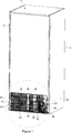
- Figure 1 - is the rear perspective view of a domestic refrigerator comprising a representative embodiment of the condenser cover of the present invention.
- Figure 2 - is the detailed view of the machine room of the refrigerator in Fig. 1.
- Figure 3 - is the schematic view of the layout plan of a cooling device machine room whereto the condenser cover of the present invention is mounted.
- FIG 1 is the rear perspective view of a domestic no-frost refrigerator.
- the refrigerator comprises a thermally-insulated cabinet-shaped body defining an inner volume wherein items to be cooled by means of a refrigeration cycle are placed.
- a cavity-shaped machine room (10) is formed close to the bottom portion of a rear wall (2) of the body (1).
- the machine room (10) is accessed through an open outer surface (14) that is defined by the lower edge of the rear wall (2) from above, a base plate (12) from below and opposite side walls (3) from the sides.
- the open outer surface (14) is covered by means of a wire-on-tube condenser cover (40) in the form of a panel so as to restrict access into the machine room (10).
- the condenser cover (40) is obtained by bending a single-piece tube (46) in U form so as to create successive transversally-lined extensions.
- Wires (48) are fixed onto the tube (46) so as to be successively lined and to increase heat transfer area.
- the wires (48) create a grill-shaped structure that allows air passage into the machine room (10) from the open outer surface (14) but that prevents access into the machine room (10).
- the machine room (10) is shown in close up.
- the condenser cover (40) is attached to the body (1) from two opposite sides so as to be parallel and adjacent to the rear wall (2).
- the holder (20) comprises a flexible first latch (22) that is mounted to the rear side of the side wall (3) from one end and that extends over the condenser cover (40) so as to catch on by being engaged crosswise with the vertical wires (48) arranged on the condenser cover (40), and two second latches (24) set apart from each other that have a similar structure as the first latch (22) and that extend in the opposite direction thereto.
- the holder (20) is detachably mounted to the body (1).
- the condenser cover (40) is removed by removing the holder (20) so as to allow access into the machine room (10).
- the first latch (22) is engaged with the wires (48) so that a flexible extension (26) thereof remains behind the wires (48).
- the condenser cover (40) is horizontally slid in the opposite direction, thus the wires (48) are engaged with the second latches (24) and the first latch (22) is screwed to the side wall (3) from the rear side.
- a radial fan (50) is fixed on an edge portion on the base plate (12) close to an inlet (42) and an outlet (44) of the condenser cover (40).
- the radial fan (50) is positioned close to an end of the machine room (10) so as to circulate the air horizontally.
- the fan (50) sucks the ambient air through an air suction gap (16) left by the condenser cover (40) over the open outer surface (14) at a position close to the side wall (3) and horizontally blows the sucked air into the machine room (10).
- the ambient air moves towards the other end of the machine room (10), cools down the functional components of the refrigeration cycle and leaves the machine room (10) through the condenser cover (40) from the far-end side.
- a coil condenser (30) is fixed to the base plate (12) in the vicinity of the fan (50) oppositely to the air blowing direction.
- the coil condenser (30) is in the form of a three dimensional matrix obtained by bending a coil tube (36) from the ends thereof and by arranging the created panels in parallel so as to form a coil.
- a condenser outlet (34) end of the coil condenser (30) that carries the refrigerant fluid is mounted to the inlet (42) of the condenser cover (40).
- a refrigerant fluid discharging compressor outlet (62) of a compressor (60) fixed to the base plate (12) close to the coil condenser (30) is mounted to a condenser inlet (32) of the coil condenser (30).
- the refrigerant fluid heating up in the compressor (60) due to increased pressure is first delivered to the coil condenser (30) adjacent to the fan (50).
- the compressor outlet (62) is connected to the coil condenser (30) by means of a dryer (66).
- the dryer (66) filters the refrigerant fluid received from the compressor (60).
- a compressor inlet (64) connected to the evaporator (not shown in the figures) sucks the gas received from the evaporator.
- Figure 3 shows the top schematic view of the machine room (10).
- the components are arranged in the flow direction of the ambient air in this order: an air suction gap (16) created by the condenser cover (40) partially leaving the open outer surface (14) open, the fan (50) horizontally blowing air so as to be behind the air suction gap (16), the coil condenser (30) opposite to the air flow direction next to the fan (50) and the compressor (60) remaining behind the coil condenser (30) relative to the fan (50).
- the temperature distribution in the machine room (10) is the densest at a region close to the refrigerant fluid discharging compressor outlet (62) of the compressor (60). Because the compressor (60) compressor the gas received from the evaporator, thus increasing the pressure and the temperature thereof.
- the refrigerant gas is cooled first in the coil condenser (30) with the ambient air accelerated by the fan (50).
- the grill structure of the condenser cover (40) mostly shields the air so as to prevent the ambient air from completely leaving through the open outer surface (14) while flowing horizontally.
- the refrigerant fluid inlet (42) of the condenser cover (40) is positioned close to the air suction gap (16).
- the ambient air sucked by the fan (50) from the air suction gap (16) and delivered to the coil condenser (30) first cools down the inlet (42) and the condenser cover (40) disposed in the vicinity thereof.
- the ambient air passes around the compressor (60) after the condenser (30) and leaves the machine room (10) close to the edge of the open outer surface (14) opposite to the air suction gap (16).
- the condenser cover (40) enables the machine room (10) to be closed so as to prevent access by mostly covering the open outer surface (14) while contacting the ambient air at a region as much as the covered portion of the open outer surface (14) so as to cool down the refrigerant fluid before being delivered to the evaporator.
- the upright outlet (44) of the condenser cover (40) passes through the insulation layer and reaches the evaporator through the body (1).
- the fan (50) provides air circulation along the inner wall of the condenser cover (40) and accelerates the refrigeration process. Moreover, the condenser cover (40) provides that less amount of air blown by the fan (50) leaks from the open outer surface (14), thus improving the cooling efficiency of the fan (50).
Landscapes
- Engineering & Computer Science (AREA)
- Physics & Mathematics (AREA)
- Mechanical Engineering (AREA)
- Thermal Sciences (AREA)
- General Engineering & Computer Science (AREA)
- Chemical & Material Sciences (AREA)
- Combustion & Propulsion (AREA)
- Compressor (AREA)
- Other Air-Conditioning Systems (AREA)
Abstract
The present invention is a cooling device comprising a thermally-insulated body (1) and a machine room (10) wherein a compressor (60), that is connected to a refrigeration cycle cooling an inner volume enclosed by the body (1), is disposed. The cooling device comprises a tube-shaped condenser cover (40) that is connected to a compressor outlet (62) of the compressor (60) in fluid communication and that is attached to the body (1) so as to partially cover an open outer surface (14) that is defined by the machine room (10) and that can be accessed from the outside.
Description
The present invention relates to cooling devices comprising a compressor and a condenser connected to a refrigeration cycle in the thermally-insulated wall thereof.
Cooling devices, in particular refrigerators, comprise a condenser and a compressor connected to a refrigeration cycle. The condenser is a heat exchanger that releases the heat absorbed during the refrigeration process to the ambient air. In different refrigerator designs, condensers in different configurations are used. One is the static condenser extending on the rear wall of the cooling device. Moreover, coil condensers providing forced convection due to the compact structure thereof can be used. In the cooling devices with a coil condenser, a fan generates an air flow, thus enabling the coil condenser to be cooled. The condenser, that is produced in the form of a wire-on-tube in order to provide an efficient heat transfer, comprises a tube bent such that each segment is parallel to the other segment, and lined wires extending perpendicular to the tube.
The Patent No. TR200900786 discloses a cooling device wherein the compressor and the condenser generally operate in the region called the cabinet base and that is situated at the bottom portion of the body. By means of a fan disposed in the compartment, air is sucked from the outer environment into the compartment and delivered onto the condenser casing that is composed of nested bodies and wherein the condenser is disposed. The air leaving the condenser casing is delivered onto the compressor, thus providing the cooling of the compressor.
The Patent No. WO2012084486 discloses a cooling device comprising a condenser that has a first portion located in front of the fan and a second portion that is integrated to the first portion and that is provided around the fan so as to surround the fan. The condenser comprises a helical refrigerant tube and wires surrounded around the tube in the form of a cage.
The aim of the present invention is to increase the heat transfer efficiency in the machine room in the cooling devices.
The present invention in order to attain the aim of the said aim is a cooling device comprising a thermally-insulated body and a machine room wherein a compressor, that is connected to a refrigeration cycle cooling an inner volume enclosed by the body, is disposed. The preferred embodiment of the present invention comprises a tube-shaped condenser cover that is connected to an outlet of the compressor in fluid communication and that is attached to the body so as to partially cover an open outer surface that is defined by the machine room and that can be accessed from the outside. Thus, at least a portion of the condenser required for heat transfer covers the open outer surface of the machine room by functioning as a cover and supports the refrigeration cycle by providing heat transfer to the outer environment. In a preferred embodiment, the condenser cover is attached to the body in an easily detachable manner. Thus, the machine room can be accessed for maintenance by removing the condenser cover. The fluid connection of the condenser cover to the compressor outlet can be a direct connection or can be realized through the intermediate connection of other functional components supporting the refrigeration cycle. The open outer surface can be provided as an outer surface of the body facing the outer environment, for example, at the bottom portion of the rear wall of the body.
The condenser cover extends parallel to an outer wall of the body. In this case, the condenser cover correspond to the contours of the body and the cooling device is enabled to be easily packaged. In a possible embodiment, the cover can have a form following the body wall of the body whereto the cover is to be mounted. Thus, the condenser cover does not deteriorate the visual integrity of the body.
The condenser cover has a grill-shaped configuration. Thus, while obstructing the entrance of foreign objects into the machine room through the opening, the condenser cover allows air transfer.
A fan is fixed into the machine room so as to cool both the compressor and the condenser cover. The fan receives the ambient air through the open outer surface and circulates the same in the machine room, thus providing forced convection, and by means of the cooling provided by the fan, using a more compact condenser becomes possible.
A coil condenser is fixed in the vicinity of the fan in the machine room and connected so as to provide fluid communication between the compressor and the condenser cover. In this case, the hot fluid leaving the compressor is first cooled in the coil condenser and brought to the temperature of the outer environment on the condenser cover. By means of the condenser cover, the condenser in the refrigeration cycle is composed of two pieces, and use of a coil condenser produced with less material in the machine room becomes possible.
The fan is positioned in the machine room such that the air circulation provided by the fan circulates through the coil condenser, the compressor and the condenser cover in this order. Thus, when the ambient air is received through the outer opening, first the coil condenser wherein the temperature of the fluid in the refrigeration cycle is at the highest is cooled. The fan blows air into the machine room in a direction parallel to the condenser cover. Thus, the fan is enabled to suck the ambient air from one side of the outer opening and discharge the same from the other side, and while the ambient air passes from one side of the condenser cover, the machine room air passes from the other side, thereby providing a forced heat transfer along the entire condenser cover.
The machine room is in the form of a cavity that is opened at the bottom portion of a rear wall of the body, the port of which defines the open outer surface. By being concealed at the bottom portion of the rear wall, the cavity is prevented from being seen from the outside and the noise of the functional components generating noise during the refrigeration cycle, such as the compressor, is enabled to be less heard from the front side.
A preferred embodiment comprises a holder with one end fixed to the rear wall and the other end holding the condenser cover. By means of the holder, the condenser cover is attached to the rear wall. Thus, the assembly of the condenser cover to the opening is facilitated. The holder is configured to hold the compressor cover parallel to the rear wall. Moreover, the holder is fixed to the rear wall so as to be adjacent to the open outer surface. By means of this configuration, the condenser cover extends over the outer opening as a continuation of the rear wall so as to provide ease of packaging.
The condenser cover comprises a single-piece tube that is bent so as to form arms extending parallel to each other in the horizontal direction. By bending the tube at a distance covering the opening, for example at the transversal distance of two opposite edges of the rear wall, the distance to be covered by the refrigerant fluid is increased. Moreover, the parallel arms enable the condenser cover to cover the opening in the horizontal direction. The condenser cover comprises an inlet that is fluidly connected to an outlet of the compressor and that extends towards the machine room. Thus, the condenser cover is enabled to extend into the machine room and to be directly connected to an outlet of another component connected to the refrigeration cycle in the machine room.
A cooling device realized in order to attain the aim of the present invention is illustrated in the attached figures, where:
Figure 1 - is the rear perspective view of a domestic refrigerator comprising a representative embodiment of the condenser cover of the present invention.
Figure 2 - is the detailed view of the machine room of the refrigerator in Fig. 1.
Figure 3 - is the schematic view of the layout plan of a cooling device machine room whereto the condenser cover of the present invention is mounted.
The elements illustrated in the figures are numbered as follows:
1 Body
2 Rear wall
3 Side wall
10 Machine compartment
12 Base plate
14 Open outer surface
16 Air suction gap
20 Holder
22 First latch
24 Second latch
26 Flexible extension
30 Coil condenser
32 Condenser inlet
34 Condenser outlet
36 Coil tube
40 Condenser cover
42 Inlet
44 Outlet
46 Tube
48 Wire
50 Fan
60 Compressor
62 Compressor outlet
64 Compressor inlet
66 Dryer
Figure 1 is the rear perspective view of a domestic no-frost refrigerator. The refrigerator comprises a thermally-insulated cabinet-shaped body defining an inner volume wherein items to be cooled by means of a refrigeration cycle are placed. A cavity-shaped machine room (10) is formed close to the bottom portion of a rear wall (2) of the body (1). The machine room (10) is accessed through an open outer surface (14) that is defined by the lower edge of the rear wall (2) from above, a base plate (12) from below and opposite side walls (3) from the sides. The open outer surface (14) is covered by means of a wire-on-tube condenser cover (40) in the form of a panel so as to restrict access into the machine room (10). The condenser cover (40) is obtained by bending a single-piece tube (46) in U form so as to create successive transversally-lined extensions. Wires (48) are fixed onto the tube (46) so as to be successively lined and to increase heat transfer area. The wires (48) create a grill-shaped structure that allows air passage into the machine room (10) from the open outer surface (14) but that prevents access into the machine room (10).
In Figure 2, the machine room (10) is shown in close up. By means of a holder (20), the condenser cover (40) is attached to the body (1) from two opposite sides so as to be parallel and adjacent to the rear wall (2). The holder (20) comprises a flexible first latch (22) that is mounted to the rear side of the side wall (3) from one end and that extends over the condenser cover (40) so as to catch on by being engaged crosswise with the vertical wires (48) arranged on the condenser cover (40), and two second latches (24) set apart from each other that have a similar structure as the first latch (22) and that extend in the opposite direction thereto.
The holder (20) is detachably mounted to the body (1). When the machine room (10) is desired to be accessed, the condenser cover (40) is removed by removing the holder (20) so as to allow access into the machine room (10). To this end, it is sufficient to detach the first latch (22) from the side wall (3). Thus, by sliding the condenser cover (40) sideways, the wires (48) are released from the second latches (24) and the condenser cover (40) is mostly freed. The first latch (22) is engaged with the wires (48) so that a flexible extension (26) thereof remains behind the wires (48). During the assembly, the condenser cover (40) is horizontally slid in the opposite direction, thus the wires (48) are engaged with the second latches (24) and the first latch (22) is screwed to the side wall (3) from the rear side.
A radial fan (50) is fixed on an edge portion on the base plate (12) close to an inlet (42) and an outlet (44) of the condenser cover (40). The radial fan (50) is positioned close to an end of the machine room (10) so as to circulate the air horizontally. The fan (50) sucks the ambient air through an air suction gap (16) left by the condenser cover (40) over the open outer surface (14) at a position close to the side wall (3) and horizontally blows the sucked air into the machine room (10). The ambient air moves towards the other end of the machine room (10), cools down the functional components of the refrigeration cycle and leaves the machine room (10) through the condenser cover (40) from the far-end side.
A coil condenser (30) is fixed to the base plate (12) in the vicinity of the fan (50) oppositely to the air blowing direction. The coil condenser (30) is in the form of a three dimensional matrix obtained by bending a coil tube (36) from the ends thereof and by arranging the created panels in parallel so as to form a coil. A condenser outlet (34) end of the coil condenser (30) that carries the refrigerant fluid is mounted to the inlet (42) of the condenser cover (40). A refrigerant fluid discharging compressor outlet (62) of a compressor (60) fixed to the base plate (12) close to the coil condenser (30) is mounted to a condenser inlet (32) of the coil condenser (30). The refrigerant fluid heating up in the compressor (60) due to increased pressure is first delivered to the coil condenser (30) adjacent to the fan (50). Thus, the air sucked by the fan (50) from the outer environment first reaches the coil condenser (30) after the fan (50). The compressor outlet (62) is connected to the coil condenser (30) by means of a dryer (66). The dryer (66) filters the refrigerant fluid received from the compressor (60). A compressor inlet (64) connected to the evaporator (not shown in the figures) sucks the gas received from the evaporator.
Figure 3 shows the top schematic view of the machine room (10). In the machine room (10), the components are arranged in the flow direction of the ambient air in this order: an air suction gap (16) created by the condenser cover (40) partially leaving the open outer surface (14) open, the fan (50) horizontally blowing air so as to be behind the air suction gap (16), the coil condenser (30) opposite to the air flow direction next to the fan (50) and the compressor (60) remaining behind the coil condenser (30) relative to the fan (50).
The temperature distribution in the machine room (10) is the densest at a region close to the refrigerant fluid discharging compressor outlet (62) of the compressor (60). Because the compressor (60) compressor the gas received from the evaporator, thus increasing the pressure and the temperature thereof. The refrigerant gas is cooled first in the coil condenser (30) with the ambient air accelerated by the fan (50). The grill structure of the condenser cover (40) mostly shields the air so as to prevent the ambient air from completely leaving through the open outer surface (14) while flowing horizontally. The refrigerant fluid inlet (42) of the condenser cover (40) is positioned close to the air suction gap (16). Thus, the ambient air sucked by the fan (50) from the air suction gap (16) and delivered to the coil condenser (30) first cools down the inlet (42) and the condenser cover (40) disposed in the vicinity thereof. The ambient air passes around the compressor (60) after the condenser (30) and leaves the machine room (10) close to the edge of the open outer surface (14) opposite to the air suction gap (16). The condenser cover (40) enables the machine room (10) to be closed so as to prevent access by mostly covering the open outer surface (14) while contacting the ambient air at a region as much as the covered portion of the open outer surface (14) so as to cool down the refrigerant fluid before being delivered to the evaporator. The upright outlet (44) of the condenser cover (40) passes through the insulation layer and reaches the evaporator through the body (1). The fan (50) provides air circulation along the inner wall of the condenser cover (40) and accelerates the refrigeration process. Moreover, the condenser cover (40) provides that less amount of air blown by the fan (50) leaks from the open outer surface (14), thus improving the cooling efficiency of the fan (50).
Claims (13)
- A cooling device comprising a thermally-insulated body (1) and a machine room (10) wherein a compressor (60), that is connected to a refrigeration cycle cooling an inner volume enclosed by the body, is disposed, characterized by comprising a tube-shaped condenser cover (40) that is connected to a compressor outlet (62) of the compressor (60) in fluid communication and that is attached to the body (1) so as to partially cover an open outer surface (14) that is defined by the machine room (10) and that can be accessed from the outside.
- A cooling device as in Claim 1, characterized by the condenser cover (40) extending parallel to an outer wall of the body (1).
- A cooling device as in any one of the above claims, characterized by the condenser cover (40) having a grill-shaped configuration.
- A cooling device as in any one of the above claims, characterized by comprising a fan (50) that is fixed to the machine room (10) and that is adjusted so as to cool down both the compressor (60) and the condenser cover (40).
- A cooling device as in Claim 4, characterized by comprising a coil condenser (30) that is fixed in the vicinity of the fan (50) in the machine room (10) and connected so as to provide fluid communication between the compressor (60) and the condenser cover (40).
- A cooling device as in Claim 5, characterized by the fan (50) that is positioned in the machine room (10) such that the air is circulated through the coil condenser (30), the compressor (60) and the condenser cover (40) respectively.
- A cooling device as in any one of the Claims 4 to 6, characterized by the fan (50) that blows air in the machine room (10) in a direction parallel to the condenser cover (40).
- A cooling device as in any one of the above claims, characterized by the machine room (10) that is in the form of a cavity that is opened at the bottom portion of a rear wall (2) of the body (1), the port of which defines the open outer surface (14).
- A cooling device as in Claim 8, characterized by a holder (20) with one end fixed to the rear wall (2) and the other end holding the condenser cover (40).
- A cooling device as in Claim 9, characterized by the holder (20) that is configured to hold the condenser cover (40) parallel to the rear wall (2).
- A cooling device as in Claim 10, characterized by the holder (20) that is fixed to the rear wall (2) in a manner adjacent to the open outer surface (14).
- A cooling device as in any one of the above claims, characterized by the condenser cover (40) comprising a single-piece tube (46) that is bent so as to form arms extending parallel to each other in the horizontal direction.
- A cooling device as in Claim 12, characterized by the condenser cover (40) comprising an inlet (42) that is fluidly connected to an outlet (44) of the compressor (60) and that extends towards the machine room (10).
Applications Claiming Priority (2)
| Application Number | Priority Date | Filing Date | Title |
|---|---|---|---|
| TR2016/06912A TR201606912A2 (en) | 2016-05-25 | 2016-05-25 | A REFRIGERANT WITH CONDENSER COVER |
| TRA2016/06912 | 2016-05-25 |
Publications (1)
| Publication Number | Publication Date |
|---|---|
| WO2017202687A1 true WO2017202687A1 (en) | 2017-11-30 |
Family
ID=58772874
Family Applications (1)
| Application Number | Title | Priority Date | Filing Date |
|---|---|---|---|
| PCT/EP2017/061980 Ceased WO2017202687A1 (en) | 2016-05-25 | 2017-05-18 | A cooling device comprising a condenser cover |
Country Status (2)
| Country | Link |
|---|---|
| TR (1) | TR201606912A2 (en) |
| WO (1) | WO2017202687A1 (en) |
Citations (7)
| Publication number | Priority date | Publication date | Assignee | Title |
|---|---|---|---|---|
| US2087257A (en) * | 1934-07-07 | 1937-07-20 | Reconstruction Finance Corp | Refrigerator cabinet |
| US2378524A (en) * | 1941-04-23 | 1945-06-19 | Gibson Refrigerator Co | Refrigerator |
| JPH0526562A (en) * | 1991-07-19 | 1993-02-02 | Matsushita Refrig Co Ltd | Condensing unit |
| US20030005720A1 (en) * | 2001-07-07 | 2003-01-09 | Lg Electronics Inc. | Refrigerator incorporating condenser functioning as backcover |
| US20030221442A1 (en) * | 2002-05-20 | 2003-12-04 | Lg Electronics Inc. | Machine room back cover integrated with a condenser for a refrigerator |
| EP2136168A1 (en) * | 2008-06-20 | 2009-12-23 | Electrolux Home Products Corporation N.V. | A cooling apparatus condenser, and a cooling apparatus including the same |
| WO2012084486A1 (en) | 2010-12-24 | 2012-06-28 | Arcelik Anonim Sirketi | A cooling device comprising a condenser cooled by a fan |
-
2016
- 2016-05-25 TR TR2016/06912A patent/TR201606912A2/en unknown
-
2017
- 2017-05-18 WO PCT/EP2017/061980 patent/WO2017202687A1/en not_active Ceased
Patent Citations (7)
| Publication number | Priority date | Publication date | Assignee | Title |
|---|---|---|---|---|
| US2087257A (en) * | 1934-07-07 | 1937-07-20 | Reconstruction Finance Corp | Refrigerator cabinet |
| US2378524A (en) * | 1941-04-23 | 1945-06-19 | Gibson Refrigerator Co | Refrigerator |
| JPH0526562A (en) * | 1991-07-19 | 1993-02-02 | Matsushita Refrig Co Ltd | Condensing unit |
| US20030005720A1 (en) * | 2001-07-07 | 2003-01-09 | Lg Electronics Inc. | Refrigerator incorporating condenser functioning as backcover |
| US20030221442A1 (en) * | 2002-05-20 | 2003-12-04 | Lg Electronics Inc. | Machine room back cover integrated with a condenser for a refrigerator |
| EP2136168A1 (en) * | 2008-06-20 | 2009-12-23 | Electrolux Home Products Corporation N.V. | A cooling apparatus condenser, and a cooling apparatus including the same |
| WO2012084486A1 (en) | 2010-12-24 | 2012-06-28 | Arcelik Anonim Sirketi | A cooling device comprising a condenser cooled by a fan |
Also Published As
| Publication number | Publication date |
|---|---|
| TR201606912A2 (en) | 2017-12-21 |
Similar Documents
| Publication | Publication Date | Title |
|---|---|---|
| KR101176459B1 (en) | Refrigerator | |
| CN209893727U (en) | Refrigerator with side ventilation holes in the side walls of the compressor compartment | |
| CN102317718B (en) | refrigerator | |
| CN109425171B (en) | Refrigerator with a door | |
| KR101520704B1 (en) | Refrigerator | |
| CN111609615A (en) | Large volume refrigerator | |
| EP2743618B1 (en) | Refrigerator for foods | |
| KR102934444B1 (en) | Refirgerator | |
| JP2001190338A (en) | Service cart | |
| CN209893744U (en) | Large-capacity refrigerator | |
| CN105972903A (en) | Freezing device | |
| WO2017202687A1 (en) | A cooling device comprising a condenser cover | |
| CN111609623B (en) | Refrigerator with L-shaped condenser | |
| JP3702120B2 (en) | Cooling system | |
| JP2012032124A (en) | Freezer for refrigerating agent | |
| KR20100050350A (en) | A refrigerator | |
| JP2020188844A (en) | Refrigeration show case | |
| CN108366680B (en) | Refrigerated merchandiser | |
| CN111351286A (en) | Refrigerator device | |
| CN110375481A (en) | Bottom has the refrigerator of Double condenser structure | |
| JP3615387B2 (en) | Cold storage freezer | |
| JP3863697B2 (en) | Refrigerator | |
| CN107949759A (en) | It is exclusively used in the rapid cooling device of domestic applications | |
| CN210625065U (en) | Refrigerator with air return inlet formed on side wall of refrigerator body | |
| JPH11264647A (en) | Deep freezer for cold-storage agent |
Legal Events
| Date | Code | Title | Description |
|---|---|---|---|
| NENP | Non-entry into the national phase |
Ref country code: DE |
|
| 121 | Ep: the epo has been informed by wipo that ep was designated in this application |
Ref document number: 17725926 Country of ref document: EP Kind code of ref document: A1 |
|
| 122 | Ep: pct application non-entry in european phase |
Ref document number: 17725926 Country of ref document: EP Kind code of ref document: A1 |