WO2017199335A1 - Separation column connection device, connection method, and analysis system - Google Patents
Separation column connection device, connection method, and analysis system Download PDFInfo
- Publication number
- WO2017199335A1 WO2017199335A1 PCT/JP2016/064606 JP2016064606W WO2017199335A1 WO 2017199335 A1 WO2017199335 A1 WO 2017199335A1 JP 2016064606 W JP2016064606 W JP 2016064606W WO 2017199335 A1 WO2017199335 A1 WO 2017199335A1
- Authority
- WO
- WIPO (PCT)
- Prior art keywords
- fitting
- separation column
- holder
- column
- separation
- Prior art date
Links
Images


Classifications
-
- G—PHYSICS
- G01—MEASURING; TESTING
- G01N—INVESTIGATING OR ANALYSING MATERIALS BY DETERMINING THEIR CHEMICAL OR PHYSICAL PROPERTIES
- G01N30/00—Investigating or analysing materials by separation into components using adsorption, absorption or similar phenomena or using ion-exchange, e.g. chromatography or field flow fractionation
- G01N30/02—Column chromatography
- G01N30/60—Construction of the column
- G01N30/6004—Construction of the column end pieces
-
- G—PHYSICS
- G01—MEASURING; TESTING
- G01N—INVESTIGATING OR ANALYSING MATERIALS BY DETERMINING THEIR CHEMICAL OR PHYSICAL PROPERTIES
- G01N30/00—Investigating or analysing materials by separation into components using adsorption, absorption or similar phenomena or using ion-exchange, e.g. chromatography or field flow fractionation
- G01N30/02—Column chromatography
- G01N30/60—Construction of the column
- G01N30/6047—Construction of the column with supporting means; Holders
-
- B—PERFORMING OPERATIONS; TRANSPORTING
- B01—PHYSICAL OR CHEMICAL PROCESSES OR APPARATUS IN GENERAL
- B01D—SEPARATION
- B01D15/00—Separating processes involving the treatment of liquids with solid sorbents; Apparatus therefor
- B01D15/08—Selective adsorption, e.g. chromatography
- B01D15/10—Selective adsorption, e.g. chromatography characterised by constructional or operational features
- B01D15/22—Selective adsorption, e.g. chromatography characterised by constructional or operational features relating to the construction of the column
-
- G—PHYSICS
- G01—MEASURING; TESTING
- G01N—INVESTIGATING OR ANALYSING MATERIALS BY DETERMINING THEIR CHEMICAL OR PHYSICAL PROPERTIES
- G01N30/00—Investigating or analysing materials by separation into components using adsorption, absorption or similar phenomena or using ion-exchange, e.g. chromatography or field flow fractionation
- G01N30/02—Column chromatography
- G01N30/26—Conditioning of the fluid carrier; Flow patterns
- G01N30/38—Flow patterns
- G01N30/46—Flow patterns using more than one column
- G01N30/461—Flow patterns using more than one column with serial coupling of separation columns
-
- G—PHYSICS
- G01—MEASURING; TESTING
- G01N—INVESTIGATING OR ANALYSING MATERIALS BY DETERMINING THEIR CHEMICAL OR PHYSICAL PROPERTIES
- G01N30/00—Investigating or analysing materials by separation into components using adsorption, absorption or similar phenomena or using ion-exchange, e.g. chromatography or field flow fractionation
- G01N30/02—Column chromatography
- G01N30/60—Construction of the column
- G01N30/6004—Construction of the column end pieces
- G01N30/6026—Fluid seals
-
- G—PHYSICS
- G01—MEASURING; TESTING
- G01N—INVESTIGATING OR ANALYSING MATERIALS BY DETERMINING THEIR CHEMICAL OR PHYSICAL PROPERTIES
- G01N30/00—Investigating or analysing materials by separation into components using adsorption, absorption or similar phenomena or using ion-exchange, e.g. chromatography or field flow fractionation
- G01N30/02—Column chromatography
- G01N30/60—Construction of the column
- G01N30/6034—Construction of the column joining multiple columns
- G01N30/6039—Construction of the column joining multiple columns in series
-
- G—PHYSICS
- G01—MEASURING; TESTING
- G01N—INVESTIGATING OR ANALYSING MATERIALS BY DETERMINING THEIR CHEMICAL OR PHYSICAL PROPERTIES
- G01N30/00—Investigating or analysing materials by separation into components using adsorption, absorption or similar phenomena or using ion-exchange, e.g. chromatography or field flow fractionation
- G01N30/02—Column chromatography
- G01N30/60—Construction of the column
- G01N30/6091—Cartridges
-
- G—PHYSICS
- G01—MEASURING; TESTING
- G01N—INVESTIGATING OR ANALYSING MATERIALS BY DETERMINING THEIR CHEMICAL OR PHYSICAL PROPERTIES
- G01N30/00—Investigating or analysing materials by separation into components using adsorption, absorption or similar phenomena or using ion-exchange, e.g. chromatography or field flow fractionation
- G01N30/02—Column chromatography
- G01N30/88—Integrated analysis systems specially adapted therefor, not covered by a single one of the groups G01N30/04 - G01N30/86
- G01N2030/8881—Modular construction, specially adapted therefor
Definitions
- the present invention relates to a separation column connection device, a connection method, and an analysis system that can be miniaturized and can realize a highly reproducible connection.
- LC liquid chromatograph
- SPE solid phase extraction
- separation of contaminants and high precision and high S / N analysis can be realized by separating the sample with a separation column packed with a packing material. It is necessary to replace the separation column depending on the sample to be measured or when the life of the separation column is reached. In order to replace these separation columns, it is common to attach and detach the fitting and the separation column using a tool such as a spanner. Depending on the skill level of the operator, there is a case where the sealing portion leaks due to poor tightening. When the leak occurs, the reproducibility such as the retention time, which is an index of the analysis performance of the sample separation, decreases. In particular, when high breakdown voltage such as high-speed LC is required, highly reproducible sealing performance is important.
- Patent Documents 1 and 2 as known examples regarding exchange of separation columns.
- the separation column is automatically replaced, and the separation column and piping (fitting) are connected without using a tool.
- Patent Documents 1 and 2 since the operation of removing from the downstream piping and connecting from the upstream side is not intended, it is inevitable that air is mixed into the separation column. As described in Patent Document 2, if there is a mechanism for driving the fitting on both the upstream side and the downstream side of the separation column, the attachment and detachment timings on the upstream side and the downstream side can be shifted. Since two are required, this leads to an increase in the size of the device. In particular, an apparatus configuration that requires a plurality of separation columns results in a very large apparatus.
- the separation column connecting device of the present invention includes a first fitting that includes a column holder that holds a separation column, and a seal portion that is connected to an upstream seal portion of the separation column and is connected to an upstream pipe.
- a second fitting holder on which a second fitting to which a downstream pipe is connected is provided, a first fitting holder, and a second fitting holder.
- the analysis system of the present invention includes a separation column connection device of the present invention, a pump for feeding a sample to the separation column through an upstream pipe, a sample injection unit for injecting the sample into the upstream pipe, and a separation column And a data processing unit for analyzing a result detected by the detection unit.
- the separation column connecting method of the present invention includes a first fitting having a seal portion connected to the upstream seal portion of the separation column and connected to the upstream pipe, and connected to the downstream seal portion of the separation column.
- a separation column is disposed between a second fitting having a sealing portion and a downstream pipe connected thereto, and a repulsive force or a resistance force is applied between the separation column and the second fitting.
- the first fitting is first connected to the separation column by bringing the first fitting and the second fitting close to each other, and the second fitting is connected to the separation column by bringing the first fitting and the second fitting closer to each other.
- a member to which one of the first fitting holder and the second fitting holder is fixed is referred to as a main body member of the separation column connecting device.
- the other fitting holder and the column holder which are not fixed are not fixed to the main body member and can be moved with respect to the main body member.
- an elastic body when the second fitting holder is brought close to the column holder, a member or mechanism that generates a repulsive force or a resistance force that prevents the approach between the two fitting holders is called an elastic body.
- the elastic body includes a compression spring, a tension spring, a mechanism composed of a cylinder and a piston containing a fluid such as gas or liquid, a rubber, a combination of a magnet that applies an attractive force or a repulsive force, and the like.
- a member that guides the column holder in the direction of movement by the drive unit is called a guide.
- the present invention it is possible to attach / detach the separation column that is removed from the downstream piping and connected from the upstream piping with a fitting drive unit on only one side. Therefore, it is possible to realize analysis with high reproducibility by preventing air contamination with an apparatus configuration that can be realized at a low cost and in a small size.
- the cross-sectional schematic diagram which shows the conventional separation column in an open state The cross-sectional schematic diagram which shows the conventional separation column in a connection state.
- the partial cross section schematic diagram which shows the example of the separation column connection apparatus in an open position The partial cross section schematic diagram which shows the example of the separation column connection apparatus in a 1st fitting connection position.
- the partial cross section schematic diagram which shows the example of the separation column connection apparatus in a connection position The plane schematic diagram which shows the example of the separation column connection apparatus in an open position.
- the schematic diagram which shows the structural example of an analysis system The cross-sectional schematic diagram which shows the structural example of a separation column connection apparatus.
- the cross-sectional schematic diagram which shows the structural example of a separation column connection apparatus The cross-sectional schematic diagram which shows the structural example of a separation column connection apparatus.
- the cross-sectional schematic diagram which shows the structural example of a separation column connection apparatus The partial cross section schematic diagram which shows the example of the separation column connection apparatus in an open position.
- the partial cross section schematic diagram which shows the example of the separation column connection apparatus in a 1st fitting connection position The partial cross section schematic diagram which shows the example of the separation column connection apparatus in a 1st fitting connection position.
- the partial cross section schematic diagram which shows the example of the separation column connection apparatus in a connection position The cross-sectional schematic diagram which shows the example of a separation column connection apparatus.
- the schematic diagram which shows the structural example of the drive part in an open position The schematic diagram which shows the structural example of the drive part in a connection position.
- the partial cross section schematic diagram which shows the example of the separation column connection apparatus in an open position The partial cross section schematic diagram which shows the example of the separation column connection apparatus in a 1st fitting connection position.
- the partial cross section schematic diagram which shows the example of the separation column connection apparatus in a connection position The partial cross section schematic diagram which shows the example of a separation column connection apparatus.
- the schematic diagram which shows the example of a separation column connection apparatus The schematic diagram which shows the example of a separation column connection apparatus.
- the schematic diagram which shows the example of a separation column connection apparatus The partial cross section schematic diagram which shows the structural example of a separation column connection apparatus.
- the cross-sectional schematic diagram which shows the example of a periphery of a fitting and a fitting holder.
- the schematic diagram which shows the example of the positioning and fixing method in a separation column connection apparatus.
- the cross-sectional schematic diagram which shows the example of the pin for positioning and fixing.
- the cross-sectional schematic diagram which shows the structural example of a separation column connection apparatus The cross-sectional schematic diagram which shows the structural example of a separation column connection apparatus.
- the cross-sectional schematic diagram which shows the structural example of a separation column connection apparatus.
- the cross-sectional schematic diagram which shows the example of a separation column connection apparatus.
- the cross-sectional schematic diagram which shows the example of a separation column connection apparatus.
- FIG. 1 which shows the time sequence example of an analysis. Schematic which shows the example of a separation column connection apparatus and the analysis system using the same. Schematic which shows the example of a separation column connection apparatus and the analysis system using the same. The schematic diagram which shows the structural example of a separation column connection apparatus. The schematic diagram which shows the structural example of a separation column connection apparatus.
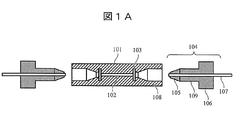
- FIG. 1A is a schematic cross-sectional view showing a conventional separation column in an open state
- FIG. 1B is a schematic cross-sectional view showing a conventional separation column in a connected state
- the separation column 101 is a cylindrical body packed with a packing material 102, and has a frit 103 that functions as a filter on both sides of the packing material, a female screw portion 108 for connecting a pipe 107, and the like.
- the pipe 107 is connected using a fitting 104 (ferrule 105 and set screw 106).
- ferrule 105 is pushed forward by rotating the male screw portion 109 of the push screw 106 with respect to the female screw portion 108 of the separation column 101 as shown by an arrow 110 in FIG.
- sealing can be performed by the ferrule 105 and the tapered portion of the separation column 101. Become. At this time, the inner diameter part of the tip of the ferrule 105 and the outer diameter part of the pipe 107 are in close contact (and bite in some cases) and sealed. Thereby, a pressure resistance of about 100 MPa is obtained depending on conditions, and high-speed LC separation by high flow rate liquid feeding is possible.
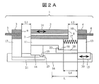
- Example 1 2A to 2D are partial cross-sectional schematic views showing an embodiment of a separation column connection device according to the present invention.
- the separation column connecting apparatus of the present embodiment includes a first fitting holder 12 fixed to a rail 16 as a main body member, a column holder 11 mounted on a guide 14 moving along the rail 16, and a drive unit 15.
- the second fitting holder 13 driven along is provided.
- a compression spring 17 as an elastic body is disposed between the second fitting holder 13 and the column holder 11.
- a separation column 2 is set in the column holder 11.
- the first fitting holder 12 is mounted with the first fitting 3 to which the upstream pipe 5 is connected in advance, and the second fitting holder 13 is connected to the second fitting 6 with the downstream pipe 6 connected in advance.
- a fitting 4 is mounted.
- the column holder 11 has a locking part 18 and the guide 14 has a locking part 19.
- the second fitting holder 13 is provided with a first stopper 20 having a protrusion 22 that contacts the locking portion 18 of the column holder 11.
- the first fitting holder 12 has a locking portion 19 of the guide 14.
- the 2nd stopper 21 which has the projection part 23 which contacts is provided.
- the column holder 11 and the first stopper 20 are in contact with each other and have a contact structure that impedes mutual free movement in the drive direction by the drive unit.
- they are referred to as a locking portion 18 and a protruding portion 22.
- the guide 14 and the second stopper 21 have a contact structure that comes into contact with each other and hinders free movement of each other in the drive direction by the drive unit.
- they are referred to as a locking portion 19 and a protruding portion 23.
- FIG. 2A is a partial cross-sectional schematic diagram showing an “open position” where the first fitting 3 and the second fitting 4 are separated from the separation column 2
- FIG. 2B is a diagram illustrating the connection between the first fitting 3 and the separation column 2.
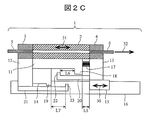
- FIG. 2C is a partial cross-sectional schematic diagram showing the “coupling position” where the first fitting 3 and the second fitting 4 are connected to the separation column 2.
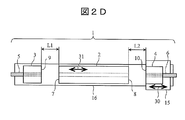
- FIG. 2D is a schematic plan view of the separation column connection device in the “open position” as viewed from above.
- the separation column 2 set in the column holder 11 in the state of FIG. 2A is first connected to the first fitting 3 in the order shown in FIG. 2A ⁇ FIG. 2B ⁇ FIG. 2C, and then connected to the second fitting 4. (Connecting step).
- the separation column 2 is opened in the order shown in FIG. 2C ⁇ FIG. 2B ⁇ FIG. 2A (opening step).
- the second fitting holder 13 on which the second fitting 4 is mounted is moved along the rail 16 in the direction of the arrow 30 by the driving unit 15. That is, the second fitting 4 is moved in the direction of the first fitting 3.
- the column holder 11 and the separation column 2 move in the direction of the arrow 31 by the force of the compression spring 17. Since the column holder 11 and the separation column 2 are mounted on the guide 14, they move together with the guide 14 along the rail 16.
- the seal portion 9 of the first fitting 3 and the seal portion 7 on the upstream side of the separation column 2 are connected, and the state shown in FIG. 2B (first fitting connection position) is obtained.
- FIG. 3 is a schematic diagram showing a configuration example of the analysis system 24 for analyzing a sample.
- the sample injected into the autosampler 28 as the sample injection unit is fed to the pipe 5 by the pump 29 by mixing the mobile phase 25 or the mobile phase 26 or both with a mixer 27.
- a mixer 27 For the mobile phases 25 and 26, an organic solvent or water is generally used.
- the sample solution flows in the direction of the arrow 32 in the order of the upstream pipe 5, the first fitting 3, the separation column 2, the second fitting 4, and the downstream pipe 6, reaches the detector 85, and is eluted. Is detected, and the data processor 86 performs analysis.
- various detection methods such as a mass spectrometer, an ultraviolet-visible light detector, a photodiode array detector, and a fluorescence detector can be used.
- connection process performed in the order of FIG. 2A ⁇ FIG. 2B ⁇ FIG. 2C is as described above, but the opening process performed in the order of FIG. 2C ⁇ FIG. 2B ⁇ FIG. 2A is basically the reverse operation of the connection process.
- the second fitting 4 is returned by the driving unit 15, the second fitting 4 is first detached from the separation column 2 in a state where the first fitting 3 is connected to the separation column 2 by the force of the compression spring 17, and then the second fitting 4 is removed. 1 fitting 3 is disengaged from the separation column 2.
- the first stopper 20 and the second stopper 21 are arranged.
- the first stopper 20 has a protrusion 22 that restricts the movement of the column holder 11, and the second stopper 21 has a protrusion 23 that restricts the movement of the guide 14.
- the column holder 11 has a locking portion 18 that contacts the protruding portion 22, and the guide 14 has a locking portion 19 that contacts the protruding portion 23. 2B ⁇ FIG. 2A in the opening process, even if the seal portion 7 of the separation column 2 and the seal portion 9 of the first fitting 3 stick and become difficult to separate, the column holder 11 is pulled by the first stopper 20. Can be forcibly released.
- the distance between the seal part 9 and the seal part 7 at the open position shown in FIG. 2A is L1
- the distance between the seal part 10 and the seal part 8 is L2
- the length of the compression spring 17 is L4.
- the length of the compression spring 17 at the coupling position shown in FIG. 2C is L5
- the distance between the locking portion 18 and the protruding portion 22 is L6
- the distance between the locking portion 19 and the protruding portion 23 is L7.
- the first stopper 20 limits the movement of the column holder 11 so that the distance between the separation column 2 and the second fitting 4 does not exceed L2.
- the second stopper 21 limits the movement of the column holder so that the distance between the first fitting 3 and the separation column 2 does not exceed L1.
- the movable range (stroke) L that can be moved to L ⁇ L1 + L2, it is possible to apply pressure further from the contact state to obtain the pressure resistance of the contact portion.
- the first fitting 3 and the first fitting holder 12 do not move, and may be fixed. Therefore, the operation of connecting the upstream first fitting 3 and the separation column 2 first by the drive unit 15 of only one side by the action of the compression spring 17 becomes possible. Further, the stoppers 20 and 21 enable highly reproducible operation.
- the second fitting holder 13 and the first stopper 20 and the first fitting holder 12 and the second stopper 21 are divided. .
- the second fitting holder 13 may also serve as the first stopper 20, and the first fitting holder 12 may also serve as the second stopper 21. Moreover, there is no problem even if the drive unit 15 and the second fitting holder 13 are integrated.
- FIG. 2D shows a schematic plan view of the state of the opening process of FIG. 2A viewed from above. For simplicity, various holders, stoppers, and springs are not shown.
- Example 1 enables the separation column attaching / detaching operation to be connected from the upstream side and removed from the downstream side piping with only one side of the fitting driving unit. Further, in this configuration, since the first fitting does not move, the upstream pipe can be shortened, and the upstream dead volume can be reduced.
- Example 2 In the present embodiment, an example of a separation column connecting device in which a fitting is constituted by a ferrule and a push screw will be described.
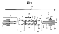
- FIG. 4 is a schematic cross-sectional view showing a configuration example of the separation column connection device of Example 2, showing an example of the separation column 2, the first fitting 3, and the second fitting 4. Since the basic configuration of the separation column connection apparatus is almost the same as that shown in FIGS. 2A to 2D, the differences will be described.
- the separation column 2 includes a filler 33 for separating a sample, and includes a frit 34 serving as a filter.
- the first fitting 3 and the second fitting 4 include a ferrule 36 and an adapter 37.
- the movement of the second fitting 4 becomes a straight-ahead operation as indicated by an arrow 30. Since the connection or release is performed by the straight movement, the female thread portion 108 of the general separation column 101 and the male thread portion 109 of the push screw 106 described in FIGS. 1A and 1B are unnecessary. Therefore, the separation column 2 has an inner diameter portion 35 without a screw portion, and an adapter 37 corresponding to a general push screw 106 has an outer diameter portion 38 without a screw portion. Even if the inner diameter portion 35 has a screw portion, there is no problem as long as the screw inner diameter is larger than the outer diameter portion 38.
- Example 2 has a merit of high versatility because it can be applied to a connector portion of a general separation column.
- Example 3 In this embodiment, an example of a separation column connecting device having a male tapered portion at the fitting tip will be described.
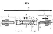
- FIG. 5 is a schematic cross-sectional view showing a configuration example of the separation column connection device of Example 3, and shows an example of the separation column 2, the first fitting 3, and the second fitting 4. Since the basic configuration of the separation column connection apparatus is almost the same as that in FIG. 2, the differences will be described.
- the separation column 2 has a female taper portion 87, and the first fitting 3 and the second fitting 4 have a male taper portion 88.
- the fitting configuration of the third embodiment is a configuration in which the ferrule and the adapter of the second embodiment are integrated, the work of biting the ferrule into the pipe in advance becomes unnecessary, and the cost can be reduced and simplified.
- Example 4 In this embodiment, an example of a separation column connecting device having a female taper portion at the fitting tip will be described.
- FIG. 6 is a schematic cross-sectional view showing a configuration example of the separation column connection device of Example 4, and shows an example of the separation column 2, the first fitting 3, and the second fitting 4. Since the basic configuration of the separation column connection apparatus is almost the same as that shown in FIGS. 2A to 2D, the differences will be described.
- the separation column 2 has a male taper part 89, and the first fitting 3 and the second fitting 4 have a female taper part 90.
- the number of exchanges on the fitting side can be reduced by forming a male taper that is easily deformed by repeated attachment and detachment on the side of the separation column that generally has a shorter life than the fitting.
- Example 5 In this embodiment, an example of a separation column connecting device having a flat fitting tip will be described.
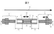
- FIG. 7 is a schematic cross-sectional view showing a configuration example of the separation column connection device of Example 5, and shows an example of the separation column 2, the first fitting 3, and the second fitting 4. Since the basic configuration of the separation column connection apparatus is almost the same as that shown in FIGS. 2A to 2D, the differences will be described.
- the separation column 2 has flat seal portions 7 and 8, and the first fitting 3 and the second fitting 4 have flat seal portions 9 and 10.
- the fitting configuration of the fifth embodiment can reduce the dead volume of the connecting portion and can simplify the part structure as compared with the tapered shape.
- Example 6 In the present embodiment, an example of a separation column connecting device having a configuration having a donut-shaped protrusion at the fitting tip will be described.
- FIG. 8 is a schematic cross-sectional view showing a configuration example of the separation column connection device of Example 6, showing an example of the separation column 2, the first fitting 3, and the second fitting 4. Since the basic configuration of the separation column connection apparatus is almost the same as that shown in FIGS. 2A to 2D, the differences will be described.
- Example 6 The fitting configuration of Example 6 can obtain a large surface pressure with a simple structure.
- Example 7 In the present embodiment, an example of a separation column connecting device configured to drive the first fitting holder will be described.
- the second fitting holder 13 is fixed to the main body member, that is, the rail 16.
- the separation column 2 and the first fitting holder 12 are movable with respect to the main body member.
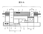
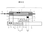
- FIGS. 9A to 9C are schematic partial cross-sectional views showing a configuration example of the separation column connection device 1 of Example 7.
- FIG. 9A is a partial cross-sectional schematic view showing an “open position” where the first fitting 3 and the second fitting 4 are separated from the separation column 2
- FIG. 9B is a diagram illustrating the connection between the first fitting 3 and the separation column 2.
- FIG. 9C is a partial cross-sectional schematic view showing the “first fitting connection position”
- FIG. 9C is a partial cross-sectional schematic view showing the “connection position” where the first fitting 3 and the second fitting 4 are connected to the separation column 2. .
- the driving unit 15 drives the first fitting holder 12 on which the first fitting 3 is mounted.
- the second fitting 4 and the second fitting holder 13 are fixed to the rail 16 and do not move.
- the compression spring 17 as an elastic body is disposed between the second fitting holder 13 and the column holder 11 as in the first embodiment.
- the first fitting holder 12 carrying the first fitting 3 is moved by the drive unit 15 along the rail 16 in the direction of the arrow 30 toward the separation column 2. Then, first, the seal part 9 of the first fitting 3 and the seal part 7 on the upstream side of the separation column 2 are connected, and the state shown in FIG. 9B (first fitting connection position) is obtained. At this time, the separation column 2 is not yet connected to the second fitting 4 by the action of the compression spring 17. Thereafter, when the first fitting holder 12 is further moved in the direction of the separation column 2 by the drive unit 15, the column holder 11 pushed by the first fitting holder 12 is moved and the compression spring 17 is contracted. Thus, the seal portion 8 on the downstream side of the separation column 2 and the seal portion 10 of the second fitting 4 are connected, resulting in a state shown in FIG. 9C (connection position).
- the separation column 2 set in the column holder 11 in the state of FIG. 9A is first connected to the first fitting 3 and then the second fitting 4 as shown in FIG. 9A ⁇ FIG. 9B ⁇ FIG. 9C. (Connecting step).
- the separation column 2 is opened in the process shown in FIGS. 9C ⁇ 9B ⁇ 9A (opening process).
- the opening process is basically the reverse operation of the connecting process, and when the first fitting holder 12 is moved away from the second fitting holder 13 by the drive unit 15, the second is first caused by the force of the compression spring 17.
- the fitting 4 is removed from the separation column 2, and then the first fitting 3 is removed from the separation column 2.
- the first stopper 20 and the second stopper 21 function to return each member to the position shown in FIG. 9A with good reproducibility in the opening process, as in the first embodiment. 9B ⁇ 9A in the opening process, even if the seal portion 7 of the separation column 2 and the seal portion 9 of the first fitting 3 are stuck and difficult to separate, the column holder 11 is fixed by the first stopper 20. In this state, the first fitting 3 is separated from the separation column 2 by the drive unit 15, so that both can be forcibly separated. In addition, by pressing the locking portion 18 of the column holder 11 against the projection 22 of the first stopper 20 with the compression spring 17 during the operation of FIG. 9A ⁇ FIG. 9B in the connecting step and FIG. 9B ⁇ FIG.
- the first fitting 3 on the upstream side and the separation column 2 are first connected by the drive unit 15 of only one side by the action of the compression spring 17, and then the separation column 2 and the first downstream side are connected.
- the operation of connecting the two fittings 4 becomes possible. Even in the opening step, it is possible to first remove the downstream second fitting 4 from the separation column 2 and then remove the upstream first fitting 3 from the separation column 2. Further, the stoppers 20 and 21 enable highly reproducible operation.
- the downstream pipe can be shortened and the downstream dead volume can be reduced.
- Example 8 In this embodiment, an example of a separation column connecting device in which a column holder and a guide are integrated will be described.
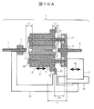
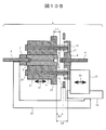
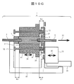
- FIG. 10A to 10C are schematic cross-sectional views showing a configuration example of the separation column connection device 1 of Example 8.
- FIG. 10A shows the “open position” where the first fitting 3 and the second fitting 4 are separated from the separation column 2
- FIG. 10B shows the “first position” where the first fitting 3 and the separation column 2 are connected
- FIG. 10C shows the “connection position” where the first fitting 3 and the second fitting 4 and the separation column 2 are connected.
- the present embodiment is characterized in that the column holder 11 has a built-in guide function as a counterpart of the guide shaft 41 for causing the separation column 2 to move straight as indicated by an arrow 31.
- the rail 16, the second stopper 21, the first fitting 3, and the like are mounted on the base 97 and fixed without moving.
- the base 97, the rail 16, and the second stopper 21 are integrated to form a main body member.
- the base 97 corresponds to a unit in which the first fitting holder 12 and the second stopper 21 of the first embodiment are integrated.
- the separation column 2 is fixed to the center portion of the column holder 11 formed so as to surround the separation column 2, and the column holder 11 is provided with a plurality of through holes through which the guide shaft 41 passes.
- the second fitting 4 to which the downstream pipe 6 is connected is fixed to the central portion of the second fitting holder 13 formed so as to surround it.
- a plurality of guide shafts 41 inserted into the through holes of the column holder 11 are fixed to the second fitting holder 13, and are driven by the drive unit 15 that moves in the direction of the arrow 30 along the rail 16.
- a compression spring 17 as an elastic body is fitted in a portion exposed between the column holder 11 and the second fitting holder 13.
- the compression spring 17 acts to separate the column holder 11 and the second fitting holder 13 from each other.
- a first stopper 20 is provided at the tip of the guide shaft 41, and the upstream surface of the column holder 11 serves as a locking portion that contacts the first stopper 20. The column holder 11 is locked by the first stopper 20 and does not fall off from the guide shaft 41.
- the drive unit 15 moves the second fitting holder 13 to the left along the arrow 30. Then, the second fitting holder 13 and the column holder 11 integrally move to the left, and the seal portion 9 of the first fitting 3 and the seal portion 7 on the upstream side of the separation column 2 are connected, and FIG. 1 fitting connection position). At this time, the separation column 2 is not yet connected to the second fitting 4 due to the action of the compression spring 17 disposed between the second fitting holder 13 and the column holder 11. Thereafter, when the second fitting holder 13 is further moved to the left by the driving unit 15, the second fitting holder 13 approaches the column holder 11 stopped while the compression spring 17 is contracted, and finally the separation column 2. The downstream seal portion 8 and the seal portion 10 of the second fitting 4 are connected, and the state shown in FIG. 10C (connection position) is obtained.
- the separation column 2 set in the column holder 11 in the state of FIG. 10A is sequentially connected to the first fitting 3 and the second fitting 4 in the order shown in FIG. 10A ⁇ FIG. 10B ⁇ FIG. 10C (connection step).
- connection step When the separation column 2 needs to be replaced, the separation column 2 is opened in the order shown in FIG. 10C ⁇ FIG. 10B ⁇ FIG. 10A (opening step).
- the opening process is basically the reverse operation of the connecting process.
- the second fitting 4 is returned to the right by the drive unit 15, the second fitting 4 is first removed from the separation column 2 by the force of the compression spring 17. After that, the first fitting 3 is detached from the separation column 2.
- the first stopper 20 and the second stopper 21 function to return each member to the position shown in FIG.
- the distance between the seal portion 9 and the seal portion 7 at the open position shown in FIG. 10A is L1
- the distance between the seal portion 10 and the seal portion 8 is L2
- the length of the compression spring 17 Is L4.
- the length of the compression spring at the coupling position shown in FIG. 10C is L5
- the distance between the first stopper 20 and the column holder 11 is L6
- the distance between the column holder 11 and the second stopper 21 is L7.
- Example 8 Since the column holder and the guide are integrated, cost reduction and simplification are possible.
- Example 9 In this embodiment, a separation column connecting device having a drive unit by a motor will be described.
- FIG. 11 is a schematic cross-sectional view illustrating a configuration example of the separation column connection device 1 according to the ninth embodiment. Since the basic configuration is almost the same as in FIGS. 2A to 2D, the differences will be described. Further, only the “open position” is shown for simplicity.
- the drive unit 15 is configured by the motor 42, the rotating shaft 43, and the stage unit 91.
- the rotation shaft 43 rotates as indicated by an arrow 44.
- the rotation shaft 43 has a feed screw portion 45, and the rotation of the feed screw portion 45 is converted into a straight movement as indicated by an arrow 30 by a mating screw (not shown) of the stage portion 91.
- the control unit 46 controls the rotation speed, torque, and rotation timing of the motor 42. Further, when it is desired to reduce the size of the motor 42 (saving labor), a large force can be obtained even with a small motor 42 by installing a reduction gear between the motor 42 and the rotating shaft 43.
- Example 9 makes it possible to automatically attach and detach the separation column. In addition, it can also be set as the apparatus which attaches / detaches manually by replacing a motor with a manual rotation means.
- Example 10 In the tenth embodiment, a separation column connecting device having a configuration in which the feed screw of the driving unit does not loosen naturally will be described.
- Equation 1 shows the conditions under which the screw does not loosen naturally.
- the feed screw portion 45 of the driving unit 15 satisfies the conditions of the above formulas 1 and 2.
- Example 10 With the configuration of Example 10, a separation column connection device that can reduce power consumption can be realized.
- Example 11 In the eleventh embodiment, a manual configuration of the drive unit will be described.
- 12A and 12B are schematic cross-sectional views illustrating a configuration example of a drive unit of the separation column connection device. 12A shows the “open position”, and FIG. 12B shows the “connection position”. The configuration of the separation column connection device other than the drive unit is almost the same as that shown in FIGS. 2A to 2D.
- the drive unit 15 is configured by the lever 50 and the arm 51 and the like.
- the lever 50 is rotated around the fixed fulcrum 54 as indicated by an arrow 55, the angle of the arm 51 is changed by the rotation of the fulcrums 52 and 53, and the position of the fulcrum 52 is changed.
- the fitting 47, the fitting holder 49, and the pipe 48 can perform a rectilinear operation as indicated by an arrow 30.
- the plunger 98 with a built-in spring inside the hole 99 corresponding to each of the “open position” and the “connection position” is provided in the fitting holder 49, thereby enabling the role of a stopper to be fixed at each position.
- any other method can be used as long as it can be fixed at each position.
- Example 11 enables the separation column to be attached and detached with a simple mechanism using a lever.
- Example 12 In the present embodiment, a separation column connecting device having a configuration in which the first fitting is connected to the separation column in advance by a tension spring will be described.
- FIGS. 13A to 13C are schematic partial cross-sectional views showing a configuration example of the separation column connection device 1 of Example 12.
- FIG. 13A shows the “open position” where the first fitting 3 and the second fitting 4 are separated from the separation column 2
- FIG. 13B shows the “first position” where the first fitting 3 and the separation column 2 are connected
- FIG. 13C shows the “coupling position” where the first fitting 3 and the second fitting 4 and the separation column 2 are coupled.
- the tension spring 56 is used as an elastic body used for connecting the first fitting 3 to the separation column 2 in advance.
- the tension spring 56 is disposed between the distal end portion of the first stopper 20 connected to the second fitting holder 13 and the locking portion 18 of the column holder 11 located closer to the second fitting holder 13 than that.
- the tension spring 56 exerts a tensile force between the tip portion of the first stopper 20 and the locking portion 18 of the column holder 11, but the movement of both is restricted by the protrusion 22 provided on the first stopper 20. Is done.
- the seal portion 8 on the downstream side of the separation column 2 and the seal portion 10 of the second fitting 4 are maintained apart by a distance L2.
- the tension spring 56 is disposed between the first stopper 20 and the column holder 11.
- the second fitting holder may be integrated with the first stopper 20 and also serve as the first stopper.
- the elastic body is regarded as being provided between the column holder and the second fitting holder.
- the separation column 2 set in the column holder 11 in the state of FIG. 13A is first connected to the first fitting 3 and then connected to the second fitting 4 as shown in FIGS. 13A ⁇ 13B ⁇ 13C.
- Connecting step In the connecting step, the second fitting 4 mounted on the second fitting holder 13 is moved toward the first fitting 3 along the rail 16 by the driving unit 15. Then, due to the force of the tension spring 56, the separation column 2 moves toward the first fitting 3 while maintaining the distance L ⁇ b> 2 with the second fitting 4.
- the seal portion 9 of the first fitting 3 and the seal portion 7 of the separation column 2 are connected, and the state shown in FIG. 13B (first fitting connection position) is obtained.
- the connecting process performed in the order of FIG. 2A ⁇ FIG. 2B ⁇ FIG. 2C is as described above, but the opening process performed in the order of FIG. 2C ⁇ FIG. 2B ⁇ FIG. 2A is basically the reverse operation of the connecting process.
- the second fitting 4 is returned by the drive unit 15, the second fitting 4 is first detached from the separation column 2 by the action of the tension spring 56, and the first fitting 3 is later detached from the separation column 2.
- the relationship between L1 to L7 is the same as in the first embodiment.
- the fitting drive unit on one side can be detached from the downstream piping and connected to the separation column connected from the upstream side.
- Example 13 In this embodiment, a separation column connecting device having a configuration in which the first fitting is connected to the separation column in advance by a combination of a cylinder and a piston will be described.
- FIG. 14 is a partial cross-sectional schematic diagram showing a configuration example of the separation column connection device 1 of Example 13. Since the basic configuration of the separation column connection apparatus is almost the same as that shown in FIGS. 2A to 2D, the differences will be described. For the sake of simplicity, only the “open position” is shown.
- a mechanism including a cylinder and a piston containing a fluid such as a gas or a liquid is used as an elastic body for connecting the first fitting 3 to the separation column 2 in advance.
- a force for pressing the first fitting 3 against the separation column 2 in advance is obtained.
- an orifice 100 penetrating the front and back of the piston 58 may be provided at the tip of the piston 58.
- the fluid damping performance is determined by the conductance of the orifice 100. It is also possible to provide a check valve or the like inside the orifice 100.
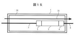
- Example 14 In this embodiment, a separation column connecting device having a column oven for adjusting the temperature of the separation column, fitting, and piping will be described.
- FIG. 15 is a schematic diagram showing a configuration example of the separation column connection device 1 of Example 14. Since the basic configuration of the separation column connection apparatus is almost the same as that shown in FIGS. 2A to 2D, the differences will be described. For convenience, only the “connection position” is shown.
- the present embodiment includes a column oven 59 as a temperature adjusting unit for adjusting the temperature of the separation column 2, the first fitting 3, and the second fitting 4.
- a column oven 59 as a temperature adjusting unit for adjusting the temperature of the separation column 2, the first fitting 3, and the second fitting 4.
- Example 14 enables analysis with high throughput and reproducibility.
- Example 15 In this example, a separation column connecting device having a temperature adjustment unit for adjusting the temperature of the separation column, fitting, and piping will be described.
- FIG. 16 is a partial cross-sectional schematic diagram showing a configuration example of the separation column connection device 1 of Example 15. Since the basic configuration of the separation column connection apparatus is almost the same as that shown in FIGS. 2A to 2D, the differences will be described. For the sake of simplicity, only the “open position” is shown.
- the present embodiment includes temperature adjusting units 60, 61, 63 for adjusting the temperature of the separation column 2, the first fitting 3, and the pipe 5.
- the temperature adjustment units 60, 61, 63 have a heater for heating, a sensor for monitoring temperature, and the like, and temperature control is performed from an external control unit (not shown).
- the column holder 11, the first fitting holder 12, and the pipe holder 62 are used as a heat block by the temperature adjustment units 60, 61, and 63.
- the heat insulating materials 64 and 65 can be arranged as shown in FIG. There may be means for adjusting the temperature of the second fitting 4 or the pipe 6.
- Example 15 enables analysis with high throughput and reproducibility as in Example 14, and can insulate the drive unit and the like.
- Example 16 In this embodiment, a separation column connecting device having a configuration in which the shapes of the first fitting and the second fitting are different will be described.
- FIG. 17 is a schematic cross-sectional view showing a configuration example of the separation column connection device of Example 16, in which examples of the separation column 2, the first fitting 3, and the second fitting 4 are shown. Since the basic configuration of the separation column connection apparatus is almost the same as that shown in FIGS. 2A to 2D, the differences will be described.
- the separation column 2 has flat seal portions 7, 8, a seal portion 9 of a donut-shaped protrusion 40 is provided at the tip of the first fitting 3, and a flat seal portion 10 is provided at the second fitting 4.
- the seal portion 9 having the donut-shaped protrusion 40 has a higher pressure resistance than the flat seal portion 10. Since the inside of the separation column 2 is filled with a packing material 33 and the upstream side has a higher pressure than the downstream side, the first fitting 3 is made a component with high pressure resistance.
- Example 17 In Example 17, a separation column connecting device having a configuration in which the materials of the first fitting and the second fitting are different will be described.
- the first fitting 3 and the second fitting 4 are made of different materials in order to increase the pressure resistance of the first fitting 3 as in the sixteenth embodiment. Actually, it is desirable that the seal portion 9 of the first fitting 3 is made of a material harder than the seal portion 10 of the second fitting 4.
- Example 18 describes a separation column connecting device having a spring between a fitting and a fitting holder.
- FIG. 18 is a schematic cross-sectional view of the periphery of the fitting and the fitting holder of this example. Since the basic configuration of the separation column connection apparatus is almost the same as that shown in FIGS. 2A to 2D, the differences will be described.
- the present embodiment is characterized in that a spring 66 is disposed between the fitting holder 49 that is moved by the driving unit 15 and the fitting 47.
- the fitting holder 49 has a through hole, and the pipe 48 connected to the fitting 47 can slide through the through hole of the fitting holder.
- Example 18 since the fitting 47 is pressed against the separation column via a spring, it is possible to prevent an excessive force from being applied to the seal portion and extend the life of the fitting and the separation column.
- Example 19 In the present embodiment, a separation column connecting device having a configuration in which the separation column and the column holder, and the fitting and the fitting holder are positioned and fixed with pins will be described.
- FIGS. 19A and 19B are schematic diagrams for explaining an example of a positioning and fixing method in the separation column connecting apparatus of Example 19.
- FIG. 19A is a schematic cross-sectional view of the periphery of the separation column 2
- FIG. 19B is a schematic cross-sectional view showing an example of a positioning and fixing pin 67. Since the basic configuration of the separation column connection apparatus is almost the same as that shown in FIGS. 2A to 2D, the differences will be described.
- a pin 67 is fixed to the column holder 11, the first fitting holder 12, and the second fitting holder 13 in advance by press-fitting or screwing. Further, the separation column 2, the first fitting 3, and the second fitting 4 are formed with holes 68 into which the pins 67 are inserted. Therefore, the separation column 2 can be set or removed along the position of the pin 67 fixed to the column holder 11 using the hole 68 of the separation column 2 as a guide. Similarly, the first fitting 3 and the second fitting 4 can be positioned and set on the first fitting holder 12 and the second fitting holder 13 by the pins 67. Since there is a slit 71 at the tip of the pin 67, it can be deformed in the radial direction by the elasticity of the member.
- the separation position 70, the first fitting position 72, the second fitting position 73, and the second fitting position 73 and each set position are uniaxially indicated by an arrow 69. It can be attached and detached by performing the operation. As shown in the figure, when the pin 67 enters the hole 68 having a small inlet diameter, the pin 67 returns to a large state when the pin 67 enters the hole 68 after being deformed small by the slit 71, and the separation column 2 is Fixed. Similarly, in the case of the pulling operation, the pin 67 can be easily pulled out by deformation.
- the attaching / detaching structure using the pins 67 may not be installed in all of the separation column 2, the first fitting 3, and the second fitting 4.
- Example 19 With the configuration of Example 19, not only the maintenance is easy because it can be set in a single-axis operation, but the number of drive shafts can be reduced when automating the transfer operation such as discarding a used separation column or setting a new separation column. Since there are few, it leads to cost reduction and miniaturization.
- Example 20 In this embodiment, a separation column connecting device having a configuration in which a separation column and a column holder, and a fitting and fitting holder are positioned and fixed by a hinge will be described.
- FIGS. 20A and 20B are schematic views for explaining an example of a positioning and fixing method in the separation column connection apparatus of Example 20.
- FIG. 20A is a schematic cross-sectional view of the periphery of the separation column 2
- FIG. 20B is a diagram showing an example of the shape of the hinge 74 when FIG. 20A is viewed from the right or left. Since the basic configuration of the separation column connection apparatus is almost the same as that shown in FIGS. 2A to 2D, the differences will be described.
- a hinge 74 is fixed to the column holder 11, the first fitting holder 12, and the second fitting holder 13 in advance by screwing or the like.
- the separation column 2, the first fitting 3, and the second fitting 4 are formed with a cylindrical portion 75 that receives a hinge 74. Therefore, the separation column 2 can be set or removed along the position of the hinge 74 fixed to the column holder 11 using the cylindrical portion 75 of the separation column 2 as a guide.
- the first fitting 3 and the second fitting 4 can be set by the hinge 74.
- the hinge 74 can be opened and closed by elastic deformation of the member.
- the separation column retracted position 70, the first fitting retracted position 72, the second fitting retracted position 73 and each set position are the same as in the nineteenth embodiment.
- the attachment / detachment structure by the hinge 74 may not be installed in all of the separation column 2, the first fitting 3, and the second fitting 4.
- the configuration of the twentieth embodiment makes it possible to set in a single axis operation as in the nineteenth embodiment.
- Example 21 In the present embodiment, a separation column connecting apparatus having a configuration in which a separation column and a fitting are connected using a tapered portion provided as a guide will be described.
- FIG. 21 is a schematic cross-sectional view showing a configuration example of the separation column connection device in Example 21, and shows an example of the separation column 2, the first fitting 3, and the second fitting 4. Since the basic configuration of the separation column connection apparatus is almost the same as that shown in FIGS. 2A to 2D, the differences will be described.
- the separation column 2, the first fitting 3, and the second fitting 4 are provided with tapered portions 76 and 77.
- Example 21 Even if the central axis of the separation column and the first fitting and the second fitting are slightly shifted, it can be connected in a state where the central axes are aligned by connecting the tapered portion to the guide.
- Example 22 In this embodiment, a separation column connecting device having a configuration in which a buffer member is disposed between a column holder and a guide will be described.
- FIG. 22 is a schematic cross-sectional view showing a configuration example of the separation column connection device in Example 22, and shows the periphery of the separation column 2. Since the basic configuration of the separation column connection apparatus is almost the same as that shown in FIGS. 2A to 2D, the differences will be described.
- a buffer member 78 is disposed between the column holder 11 and the guide 14.
- the buffer member 78 rubber, sponge, spring, fluid damper or the like can be used.
- the buffer member 78 may be disposed between the separation column 2 and the column holder 11.
- a buffer member may be disposed between the fitting and the fitting holder or between the fitting holder and the drive unit 15.
- Example 22 Even if the separation column and the center axis of the first fitting or the second fitting are slightly displaced, the center axis of the separation column is adjusted to the first fitting and the second fitting by the likelihood of the buffer member. Can be aligned with the central axis of
- Example 23 In the present embodiment, a separation column connection apparatus having a sensor for detecting a solution and a sensor for detecting the position of a moving member and capable of performing a drive unit moving sequence based on the information will be described.
- FIG. 23 is a partial cross-sectional schematic diagram showing a configuration example of the separation column connection device 1 of Example 23. Since the basic configuration of the separation column connection apparatus is almost the same as that shown in FIGS. 2A to 2D, the differences will be described.
- a first tray 79 that collects the solution flowing out from the outlet of the first fitting 3 and a first liquid sensor 80 that detects the solution are provided, and the solution flowing out from the outlet of the separation column 2 is further removed. It has the 2nd tray 82 to collect
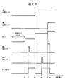
- FIG. 24 is an explanatory diagram showing an example of a time sequence of analysis using the separation column connection device of this example.
- liquid feeding is started by the pump 29 (t1).
- the flow rate of the pump 29 may be small.
- the solution flowing out from the outlet of the first fitting 3 accumulates in the first tray 79 to some extent, and when the first liquid sensor 80 reacts, the output of the motor 42 of the drive unit 15 is turned on (t2). .
- the first position sensor 81 reacts to increase the flow rate of the pump 29 and send it to the separation column 2 (t3). ). Since the liquid is sent to the separation column 2 having a high flow resistance, the time can be shortened by sending the liquid at a high flow rate, but it is not always necessary to change the flow rate at t3. At this time, the output of the motor 42 is turned off. In this state, the first fitting 3 and the separation column 2 are connected only by the force of the compression spring 17, but the upstream pressure of the separation column 2 depending on the flow rate can be hermetically sealed by the force of the compression spring 17. If there is no problem.
- the second position sensor 84 reacts when the motor 42 continues to rotate and the seal portion 8 of the separation column 2 and the seal portion 10 of the second fitting 4 are connected, and the flow rate of the pump 29 is set as an analysis condition (t5).
- the output of the motor 42 is turned off (t6). By turning off the output after T seconds, it is possible to reliably rotate the motor 42 with a desired torque and to apply a sufficient pressing force to each seal portion.
- the set output of the motor 42 at t2 and t4 may be the same or different. If there is no problem with the power consumption or heat generation of the motor 42, it is not necessary to turn it off at t3 or t6.
- the air into the flow path is obtained by the sequence of connecting the first fitting 3 and the separation column 2 and connecting the separation column 2 and the second fitting 4 while flowing the solution and detecting the outflow. It is possible to minimize the risk of contamination.
- the liquid sensor may be omitted as long as the first fitting and the elution time from the separation column can be derived from the relationship between the pump flow rate and the pipe inner diameter.
- the position sensor may not be provided as long as the fitting position and the column position can be derived from the relationship between the motor rotation speed, the feed screw pitch, and the energization time.
- Example 23 is a sequence in which a connection is made while flowing a solution, it is possible to minimize the risk of air mixing into the flow path.
- Example 24 In the present embodiment, a separation column connecting device having a configuration having a plurality of separation columns and driving units will be described.
- FIG. 25 is a schematic diagram showing a configuration example of the separation column connection device 1 of Example 24 and the analysis system 24 using the same. Since the basic configuration of the separation column connecting device and the analysis system is almost the same as that shown in FIGS. 2A to 2D and FIG. 3, differences will be described.
- This embodiment has a plurality of separation columns and driving units.
- the separation columns 2a and 2b there are two separation columns 2a and 2b, two sets of first fittings 3a and 3b, second fittings 4a and 4b, and driving units 15a and 15b.
- the drive unit 15a and the drive unit 15b can operate independently.
- the solution is made to flow through a desired separation column by switching the valves 92 and 93 to perform the analysis.
- the analysis system including two separation columns is shown in the figure, the number of separation columns is not limited to two, and may be three or more.
- Example 24 by using a plurality of separation columns and switching them with valves, it is possible to perform washing and equilibration in the other separation column during analysis in one separation column, thereby improving throughput. Leads to. Further, it is possible to reduce the size of a high throughput apparatus equipped with a plurality of separation columns.
- Example 25 In this embodiment, a separation column connecting device having a plurality of separation columns will be described.
- FIG. 26 is a schematic diagram illustrating a configuration example of the separation column connection device 1 of Example 25 and the analysis system 24 using the same. Since the basic configuration of the separation column connecting device and the analysis system is almost the same as that shown in FIGS. 2A to 2D and FIG. 3, differences will be described. In this embodiment, there are a plurality of separation columns, but there is one drive unit.
- two separation columns 2a and 2b, and two sets of first fittings 3a and 3b and second fittings 4a and 4b associated therewith are provided.
- the second fittings 4a and 4b are driven by one common driving unit 15.
- the solution is made to flow through a desired separation column by switching the valves 92 and 93 to perform the analysis.
- Example 25 since a plurality of separation columns and fittings are attached and detached with a single drive unit, the apparatus can be reduced in size.
- Example 26 In this embodiment, a separation column connecting device having a cartridge capable of storing a plurality of separation columns will be described.
- FIG. 27 is a schematic diagram showing a configuration example of the separation column connection device in Example 26, and shows an example of the separation column 2, the first fitting 3, and the second fitting 4. Since the basic configuration of the separation column connection apparatus is almost the same as that shown in FIGS. 2A to 2D, the differences will be described.
- the separation column 2 may be as small as about 10 mm in length and may be difficult to handle. With the configuration of Example 26, the handleability is improved by storing the separation column in a cartridge.
- Example 27 In the twenty-seventh embodiment, a separation column connecting apparatus having a drive unit that drives a separation column in a direction orthogonal to a driving direction for connecting the separation column and the fitting will be described.
- FIG. 28 is a schematic diagram showing a configuration example of the separation column connection device in Example 27, and shows an example of the separation column 2, the first fitting 3, and the second fitting 4. Since the basic configuration of the separation column connection apparatus is almost the same as that shown in FIGS. 2A to 2D, the differences will be described.
- the cartridge 94 that can store a plurality of separation columns 2 has a second drive unit 95 that moves in a direction orthogonal to the movement direction indicated by the arrow 30 of the drive unit 15.
- the separation column 2 to be used can be switched by moving the cartridge 94 as indicated by an arrow 96 by the second drive unit 95.
- Example 27 makes it possible to easily switch the separation column.
- the effects of the present invention can be obtained even in a device configuration in which the characteristic elements of each device configuration are combined.
- various systems such as a rectilinear mechanism such as an air cylinder and a mechanism that converts rotation to rectilinear motion such as a cam or a rack gear can be used.
- a member such as rubber can be used for the elastic body for connecting the first fitting and the separation column in advance.
- this invention is not limited to the above-mentioned Example, Various modifications are included.
- the above-described embodiments have been described in detail for easy understanding of the present invention, and are not necessarily limited to those having all the configurations described.
- a part of the configuration of one embodiment can be replaced with the configuration of another embodiment, and the configuration of another embodiment can be added to the configuration of one embodiment.
Abstract
Description
[実施例1]
図2A~2Dは、本発明による分離カラム接続装置の一実施例を示す部分断面模式図である。 Examples of the present invention will be described below.
[Example 1]
2A to 2D are partial cross-sectional schematic views showing an embodiment of a separation column connection device according to the present invention.
本実施例では、フェラルと押しネジでフィッティングを構成している分離カラム接続装置の例について説明する。 [Example 2]
In the present embodiment, an example of a separation column connecting device in which a fitting is constituted by a ferrule and a push screw will be described.
本実施例では、フィッティング先端にオステーパ部を有する構成の分離カラム接続装置の例について説明する。 [Example 3]
In this embodiment, an example of a separation column connecting device having a male tapered portion at the fitting tip will be described.
本実施例では、フィッティング先端にメステーパ部を有する構成の分離カラム接続装置の例について説明する。 [Example 4]
In this embodiment, an example of a separation column connecting device having a female taper portion at the fitting tip will be described.
本実施例では、フィッティング先端がフラット形状である分離カラム接続装置の例について説明する。 [Example 5]
In this embodiment, an example of a separation column connecting device having a flat fitting tip will be described.
本実施例では、フィッティング先端にドーナツ状の突起がある構成の分離カラム接続装置の例について説明する。 [Example 6]
In the present embodiment, an example of a separation column connecting device having a configuration having a donut-shaped protrusion at the fitting tip will be described.
本実施例では、第1のフィッティングホルダを駆動する構成の分離カラム接続装置の例について説明する。本実施例では第2のフィッティングホルダ13が本体部材、即ちレール16に固定されている。分離カラム2及び第1のフィッティングホルダ12は本体部材に対して可動になっている。 [Example 7]
In the present embodiment, an example of a separation column connecting device configured to drive the first fitting holder will be described. In the present embodiment, the second
本実施例では、カラムホルダとガイドが一体構成の分離カラム接続装置の例について説明する。 [Example 8]
In this embodiment, an example of a separation column connecting device in which a column holder and a guide are integrated will be described.
本実施例では、モータによる駆動部を有する構成の分離カラム接続装置について説明する。 [Example 9]
In this embodiment, a separation column connecting device having a drive unit by a motor will be described.
実施例10では、駆動部の送りネジが自然に緩まない構成の分離カラム接続装置について説明する。 [Example 10]
In the tenth embodiment, a separation column connecting device having a configuration in which the feed screw of the driving unit does not loosen naturally will be described.
[式1]

[Formula 1]
[式2]

[Formula 2]
実施例11では、手動による駆動部の構成について説明する。 [Example 11]
In the eleventh embodiment, a manual configuration of the drive unit will be described.
本実施例では、引張りバネにより第1のフィッティングを先行して分離カラムと連結する構成の分離カラム接続装置について説明する。 [Example 12]
In the present embodiment, a separation column connecting device having a configuration in which the first fitting is connected to the separation column in advance by a tension spring will be described.
本実施例では、シリンダとピストンの組合せにより第1のフィッティングを先行して分離カラムと連結する構成の分離カラム接続装置について説明する。 [Example 13]
In this embodiment, a separation column connecting device having a configuration in which the first fitting is connected to the separation column in advance by a combination of a cylinder and a piston will be described.
本実施例では、分離カラム、フィッティング、配管を温度調節するためのカラムオーブンを有する構成の分離カラム接続装置について説明する。 [Example 14]
In this embodiment, a separation column connecting device having a column oven for adjusting the temperature of the separation column, fitting, and piping will be described.
本実施例では、分離カラム、フィッティング、配管を温度調節するための温度調整部を有する構成の分離カラム接続装置について説明する。 [Example 15]
In this example, a separation column connecting device having a temperature adjustment unit for adjusting the temperature of the separation column, fitting, and piping will be described.
本実施例では、第1のフィッティングと第2のフィッティングの形状が異なる構成の分離カラム接続装置について説明する。 [Example 16]
In this embodiment, a separation column connecting device having a configuration in which the shapes of the first fitting and the second fitting are different will be described.
実施例17では、第1のフィッティングと第2のフィッティングの材質が異なる構成の分離カラム接続装置について説明する。 [Example 17]
In Example 17, a separation column connecting device having a configuration in which the materials of the first fitting and the second fitting are different will be described.
実施例18では、フィッティングとフィッティングホルダの間にバネを有する構成の分離カラム接続装置について説明する。 [Example 18]
Example 18 describes a separation column connecting device having a spring between a fitting and a fitting holder.
本実施例では、分離カラムとカラムホルダやフィッティングとフィッティングホルダの位置決め及び固定をピンで行う構成の分離カラム接続装置について説明する。 [Example 19]
In the present embodiment, a separation column connecting device having a configuration in which the separation column and the column holder, and the fitting and the fitting holder are positioned and fixed with pins will be described.
本実施例では、分離カラムとカラムホルダやフィッティングとフィッティングホルダの位置決め及び固定をヒンジで行う構成の分離カラム接続装置について説明する。 [Example 20]
In this embodiment, a separation column connecting device having a configuration in which a separation column and a column holder, and a fitting and fitting holder are positioned and fixed by a hinge will be described.
本実施例では、分離カラムとフィッティングの接続を、各々に設けたテーパ部をガイドにして行う構成の分離カラム接続装置について説明する。 [Example 21]
In the present embodiment, a separation column connecting apparatus having a configuration in which a separation column and a fitting are connected using a tapered portion provided as a guide will be described.
本実施例では、カラムホルダとガイドの間に緩衝部材を配置した構成の分離カラム接続装置について説明する。 [Example 22]
In this embodiment, a separation column connecting device having a configuration in which a buffer member is disposed between a column holder and a guide will be described.
本実施例では、溶液を検出するセンサや移動する部材の位置を検出するセンサを有し、その情報を元に駆動部移動のシーケンスを行うことができる分離カラム接続装置について説明する。 [Example 23]
In the present embodiment, a separation column connection apparatus having a sensor for detecting a solution and a sensor for detecting the position of a moving member and capable of performing a drive unit moving sequence based on the information will be described.
本実施例では、分離カラムと駆動部を複数有する構成の分離カラム接続装置について説明する。 [Example 24]
In the present embodiment, a separation column connecting device having a configuration having a plurality of separation columns and driving units will be described.
また、複数の分離カラムを搭載する高スループット装置における小型化も可能である。 In the configuration of Example 24, by using a plurality of separation columns and switching them with valves, it is possible to perform washing and equilibration in the other separation column during analysis in one separation column, thereby improving throughput. Leads to.
Further, it is possible to reduce the size of a high throughput apparatus equipped with a plurality of separation columns.
本実施例では、分離カラムを複数有する構成の分離カラム接続装置について説明する。 [Example 25]
In this embodiment, a separation column connecting device having a plurality of separation columns will be described.
本実施例では、複数の分離カラムを収納できるカートリッジを有する分離カラム接続装置について説明する。 [Example 26]
In this embodiment, a separation column connecting device having a cartridge capable of storing a plurality of separation columns will be described.
実施例27では、分離カラムとフィッティングの接続用の駆動方向に対して直交する方向に分離カラムを駆動する駆動部を有する構成の分離カラム接続装置について説明する。 [Example 27]
In the twenty-seventh embodiment, a separation column connecting apparatus having a drive unit that drives a separation column in a direction orthogonal to a driving direction for connecting the separation column and the fitting will be described.
3…第1のフィッティング
4…第2のフィッティング
5…配管
6…配管
7…シール部
8…シール部
9…シール部
10…シール部
11…カラムホルダ
12…第1のフィッティングホルダ
13…第2のフィッティングホルダ
14…ガイド
15…駆動部
16…レール
17…圧縮バネ
20…第1のストッパ
21…第2のストッパ
41…ガイド軸
42…モータ
50…レバー
51…アーム
56…引張りバネ
57…シリンダ
58…ピストン
80…第1の液体センサ
81…第1の位置センサ
83…第2の液体センサ
84…第2の位置センサ
85…検出器
86…データ処理部
94…カートリッジ 2 ...
Claims (15)
- 分離カラムを保持するカラムホルダと、
前記分離カラムの上流側のシール部と連結するシール部を備え上流側の配管が接続された第1のフィッティングを搭載する第1のフィッティングホルダと、
前記分離カラムの下流側のシール部と連結するシール部を備え下流側の配管が接続された第2のフィッティングを搭載する第2のフィッティングホルダと、
前記第1のフィッティングホルダと前記第2のフィッティングホルダのいずれか一方が固定された本体部材と、
前記本体部材に固定されていない前記第1のフィッティングホルダ又は前記第2のフィッティングホルダを前記本体部材に対して移動させる駆動部と、
前記カラムホルダを前記駆動部による移動方向に案内するガイドと、
前記カラムホルダと前記第2のフィッティングホルダとの間に設けられた弾性体と、
を有する分離カラム接続装置。 A column holder for holding a separation column;
A first fitting holder equipped with a first fitting provided with a seal portion connected to an upstream seal portion of the separation column and connected to an upstream pipe;
A second fitting holder equipped with a second fitting to which a downstream pipe is connected, the second fitting holder having a sealing part connected to the downstream sealing part of the separation column;
A body member to which one of the first fitting holder and the second fitting holder is fixed;
A drive unit for moving the first fitting holder or the second fitting holder that is not fixed to the body member with respect to the body member;
A guide for guiding the column holder in the moving direction by the driving unit;
An elastic body provided between the column holder and the second fitting holder;
Separation column connection device having - 前記第1のフィッティングと前記第2のフィッティングが前記分離カラムから離れた開放位置において前記分離カラムの上流側のシール部と前記第1のフィッティングのシール部との間の距離をL1、前記分離カラムの下流側のシール部と前記第2のフィッティングのシール部との間の距離をL2、前記第1のフィッティングと前記第2のフィッティングが前記分離カラムに連結した連結位置と前記開放位置の間における前記弾性体の変位量をL3、前記駆動部による可動域をLとするとき、
L≧L1+L2、
L3=L2
である請求項1記載の分離カラム接続装置。 L1 represents the distance between the seal portion on the upstream side of the separation column and the seal portion of the first fitting at the open position where the first fitting and the second fitting are separated from the separation column. The distance between the downstream seal portion and the seal portion of the second fitting is L2, between the connection position where the first fitting and the second fitting are connected to the separation column, and the open position. When the displacement amount of the elastic body is L3 and the movable range by the driving unit is L,
L ≧ L1 + L2,
L3 = L2
The separation column connection device according to claim 1. - 前記第2のフィッティングホルダは、前記分離カラムと前記第2のフィッティングの間の距離がL2を超えないように前記カラムホルダの移動を制限する第1のストッパを備える、請求項2記載の分離カラム接続装置。 The separation column according to claim 2, wherein the second fitting holder includes a first stopper that restricts movement of the column holder so that a distance between the separation column and the second fitting does not exceed L2. Connected device.
- 前記第1のストッパと前記カラムホルダは、前記駆動部による駆動方向にお互いの自由な移動を阻害する接触部を有し、
前記第1のストッパの接触部と前記カラムホルダの接触部との間の距離が、前記分離カラムが連結位置にあるときにL2である、請求項3記載の分離カラム接続装置。 The first stopper and the column holder have a contact portion that inhibits free movement of each other in the driving direction by the driving portion,
The separation column connection device according to claim 3, wherein a distance between the contact portion of the first stopper and the contact portion of the column holder is L2 when the separation column is in the connection position. - 前記第1のフィッティングホルダは、前記第1のフィッティングと前記分離カラムの間の距離がL1を超えないように前記カラムホルダの移動を制限する第2のストッパを備える、請求項2記載の分離カラム接続装置。 The separation column according to claim 2, wherein the first fitting holder includes a second stopper that restricts movement of the column holder so that a distance between the first fitting and the separation column does not exceed L1. Connected device.
- 前記第2のストッパと前記ガイド又は前記カラムホルダは、前記駆動部による駆動方向にお互いの自由な移動を阻害する接触構造を有し、
前記第2のストッパの接触部と前記ガイド又は前記カラムホルダの接触部との間の距離が、前記分離カラムが連結位置にあるときにL1である、請求項5記載の分離カラム接続装置。 The second stopper and the guide or the column holder have a contact structure that inhibits mutual free movement in the driving direction by the driving unit,
6. The separation column connection device according to claim 5, wherein a distance between the contact portion of the second stopper and the contact portion of the guide or the column holder is L1 when the separation column is in the coupling position. - 前記第1のフィッティングホルダが前記本体部材に固定されており、前記駆動部は前記第2のフィッティングホルダを前記本体部材に対して移動させる、請求項1記載の分離カラム接続装置。 The separation column connection device according to claim 1, wherein the first fitting holder is fixed to the main body member, and the driving unit moves the second fitting holder relative to the main body member.
- 前記第2のフィッティングホルダが前記本体部材に固定されており、前記駆動部は前記第1のフィッティングホルダを前記本体部材に対して移動させる、請求項1記載の分離カラム接続装置。 The separation column connecting device according to claim 1, wherein the second fitting holder is fixed to the main body member, and the driving unit moves the first fitting holder relative to the main body member.
- 前記駆動部は送りネジを備える、請求項1記載の分離カラム接続装置。 The separation column connecting device according to claim 1, wherein the driving unit includes a feed screw.
- 前記分離カラム、前記第1のフィッティング、前記第2のフィッティング、前記第1のフィッティングに接続された前記上流側の配管、前記第2のフィッティングに接続された前記下流側の配管の少なくとも一つを温度調節する温度調整部を有する、請求項1記載の分離カラム接続装置。 At least one of the separation column, the first fitting, the second fitting, the upstream pipe connected to the first fitting, and the downstream pipe connected to the second fitting The separation column connecting device according to claim 1, further comprising a temperature adjusting unit that adjusts the temperature.
- 前記第1のフィッティングの出口から流れ出る溶液を検知する第1の液体センサと、前記分離カラムの出口から流れ出る溶液を検知する第2の液体センサを有する、請求項1記載の分離カラム接続装置。 The separation column connecting device according to claim 1, further comprising: a first liquid sensor that detects a solution flowing out from an outlet of the first fitting; and a second liquid sensor that detects a solution flowing out from the outlet of the separation column.
- 分離カラムを保持するカラムホルダと、
前記分離カラムの上流側のシール部と連結するシール部を備え上流側の配管が接続された第1のフィッティングを搭載する第1のフィッティングホルダと、
前記分離カラムの下流側のシール部と連結するシール部を備え下流側の配管が接続された第2のフィッティングを搭載する第2のフィッティングホルダと、
前記第1のフィッティングホルダと前記第2のフィッティングホルダのいずれか一方が固定された本体部材と、
前記本体部材に固定されていない前記第1のフィッティングホルダ又は前記第2のフィッティングホルダを前記本体部材に対して移動させる駆動部と、
前記カラムホルダを前記駆動部による移動方向に案内するガイドと、
前記カラムホルダと前記第2のフィッティングホルダとの間に設けられた弾性体と、を有する分離カラム接続装置と、
前記上流側の配管を通して前記分離カラムに試料を送液するポンプと、
前記上流側の配管に試料を注入するための試料注入部と、
前記分離カラムからの溶出成分を検出する検出部と、
前記検出部で検出した結果を分析するデータ処理部と、
を有する分析システム。 A column holder for holding a separation column;
A first fitting holder equipped with a first fitting provided with a seal portion connected to an upstream seal portion of the separation column and connected to an upstream pipe;
A second fitting holder equipped with a second fitting to which a downstream pipe is connected, the second fitting holder having a sealing part connected to the downstream sealing part of the separation column;
A body member to which one of the first fitting holder and the second fitting holder is fixed;
A drive unit for moving the first fitting holder or the second fitting holder that is not fixed to the body member with respect to the body member;
A guide for guiding the column holder in the moving direction by the driving unit;
A separation column connecting device having an elastic body provided between the column holder and the second fitting holder;
A pump for feeding a sample to the separation column through the upstream pipe;
A sample injection section for injecting a sample into the upstream pipe;
A detection unit for detecting an elution component from the separation column;
A data processing unit for analyzing a result detected by the detection unit;
Having an analysis system. - 分離カラムの上流側のシール部と連結するシール部を備え上流側の配管が接続された第1のフィッティングと、前記分離カラムの下流側のシール部と連結するシール部を備え下流側の配管が接続された第2のフィッティングとの間に前記分離カラムを配置し、
前記分離カラムと前記第2のフィッティングの間に反発力あるいは抵抗力を作用させながら前記第1のフィッティングと前記第2のフィッティングを近づけて最初に前記第1のフィッティングを前記分離カラムに接続し、
前記第1のフィッティングと前記第2のフィッティングを更に近づけて前記第2のフィッティングを前記分離カラムに接続する、分離カラム接続方法。 A first fitting provided with a seal portion connected to an upstream seal portion of the separation column and connected to an upstream side pipe; and a downstream side pipe provided with a seal portion connected to the downstream seal portion of the separation column. Placing the separation column between the connected second fittings;
Firstly connecting the first fitting to the separation column by bringing the first fitting and the second fitting close while applying a repulsive force or a resistance force between the separation column and the second fitting,
A separation column connection method, wherein the first fitting and the second fitting are brought closer to each other to connect the second fitting to the separation column. - 前記上流側の配管から流した溶液が前記第1のフィッティングの出口から流れ出た後で前記第1のフィッティングを前記分離カラムに接続し、
前記溶液が前記分離カラムの出口から流れ出た後で前記第2のフィッティングを前記分離カラムに接続する、請求項13記載の分離カラム接続方法。 After the solution flowing from the upstream pipe flows out from the outlet of the first fitting, the first fitting is connected to the separation column;
The separation column connection method according to claim 13, wherein the second fitting is connected to the separation column after the solution flows out from the outlet of the separation column. - 前記第1のフィッティングの出口から流れ出た前記溶液を第1の液体センサで検知したのち前記第1のフィッティングを前記分離カラムに接続し、
前記分離カラムの出口から流れ出た前記溶液を第2の液体センサで検知したのち前記第2のフィッティングを前記分離カラムに接続する、請求項14記載の分離カラム接続方法。 After the solution flowing out from the outlet of the first fitting is detected by a first liquid sensor, the first fitting is connected to the separation column;
The separation column connection method according to claim 14, wherein the second fitting is connected to the separation column after the solution flowing out from the outlet of the separation column is detected by a second liquid sensor.
Priority Applications (6)
| Application Number | Priority Date | Filing Date | Title |
|---|---|---|---|
| JP2018517968A JP6611398B2 (en) | 2016-05-17 | 2016-05-17 | Separation column connection device, connection method and analysis system |
| GB1816419.4A GB2564603B (en) | 2016-05-17 | 2016-05-17 | Separation column connection device, connection method, and analysis system |
| DE112016006724.0T DE112016006724T5 (en) | 2016-05-17 | 2016-05-17 | COLUMN CONNECTION DEVICE, CONNECTION METHOD AND ANALYSIS SYSTEM |
| CN201680084536.3A CN109073610B (en) | 2016-05-17 | 2016-05-17 | Separation column connection device, connection method and analysis system |
| US16/097,145 US10921296B2 (en) | 2016-05-17 | 2016-05-17 | Separation column connection device, connection method, and analysis system |
| PCT/JP2016/064606 WO2017199335A1 (en) | 2016-05-17 | 2016-05-17 | Separation column connection device, connection method, and analysis system |
Applications Claiming Priority (1)
| Application Number | Priority Date | Filing Date | Title |
|---|---|---|---|
| PCT/JP2016/064606 WO2017199335A1 (en) | 2016-05-17 | 2016-05-17 | Separation column connection device, connection method, and analysis system |
Publications (1)
| Publication Number | Publication Date |
|---|---|
| WO2017199335A1 true WO2017199335A1 (en) | 2017-11-23 |
Family
ID=60324944
Family Applications (1)
| Application Number | Title | Priority Date | Filing Date |
|---|---|---|---|
| PCT/JP2016/064606 WO2017199335A1 (en) | 2016-05-17 | 2016-05-17 | Separation column connection device, connection method, and analysis system |
Country Status (6)
| Country | Link |
|---|---|
| US (1) | US10921296B2 (en) |
| JP (1) | JP6611398B2 (en) |
| CN (1) | CN109073610B (en) |
| DE (1) | DE112016006724T5 (en) |
| GB (1) | GB2564603B (en) |
| WO (1) | WO2017199335A1 (en) |
Cited By (8)
| Publication number | Priority date | Publication date | Assignee | Title |
|---|---|---|---|---|
| WO2018126064A3 (en) * | 2016-12-29 | 2018-08-30 | PureHoney Technologies, Inc. | Single-use, disposable high-pressure liquid chromatography columns for high-throughput analysis |
| WO2020175651A1 (en) * | 2019-02-27 | 2020-09-03 | 株式会社日立ハイテク | Column oven of analyzing device |
| JP2021021585A (en) * | 2019-07-25 | 2021-02-18 | 株式会社日立ハイテク | Column and chromatograph device |
| JP7058402B1 (en) | 2021-02-26 | 2022-04-22 | 株式会社プレッパーズ | Liquid chromatograph nozzle and liquid chromatograph |
| WO2022153686A1 (en) * | 2021-01-13 | 2022-07-21 | 株式会社日立ハイテク | Separation column connection device and separation device |
| WO2022224539A1 (en) | 2021-04-22 | 2022-10-27 | 株式会社日立ハイテク | Chromatograph |
| JP7336104B2 (en) | 2021-02-26 | 2023-08-31 | 株式会社プレッパーズ | column unit |
| JP7388232B2 (en) | 2020-02-18 | 2023-11-29 | 東ソー株式会社 | Adapter for liquid chromatography |
Families Citing this family (4)
| Publication number | Priority date | Publication date | Assignee | Title |
|---|---|---|---|---|
| JP7147594B2 (en) * | 2019-01-28 | 2022-10-05 | 株式会社島津製作所 | chromatography detector |
| DE102019212150A1 (en) * | 2019-08-13 | 2021-02-18 | Agilent Technologies, Inc. | A system comprising a chromatography column adapter, a chromatography column and a capillary |
| EP4143562A1 (en) * | 2020-04-29 | 2023-03-08 | Waters Technologies Corporation | Establishing fluidic connections between chromatography components |
| DE102020133422A1 (en) | 2020-12-14 | 2022-06-15 | Agilent Technologies, Inc. - A Delaware Corporation - | Mounting device for mounting a sample separation device |
Citations (6)
| Publication number | Priority date | Publication date | Assignee | Title |
|---|---|---|---|---|
| JPH07239325A (en) * | 1994-02-25 | 1995-09-12 | Sekisui Chem Co Ltd | Column connector for high speed liquid chromatography |
| JP2007078436A (en) * | 2005-09-13 | 2007-03-29 | Jasco Corp | Column connector |
| US20070084982A1 (en) * | 2005-10-17 | 2007-04-19 | Agilent Technologies, Inc. | Holding device for chromatograph columns |
| WO2012058513A1 (en) * | 2010-10-29 | 2012-05-03 | Thermo Finnigan Llc | Apparatus and method for coupling tubing to chromatographic column |
| US8307541B2 (en) * | 2008-12-23 | 2012-11-13 | Optimize Technologies, Inc. | Assembly for placing an insert into communication with an analytical chemical instrument |
| WO2013095964A2 (en) * | 2011-12-21 | 2013-06-27 | Waters Technologies Corporation | Establishing fluidic connections between chromatography components |
Family Cites Families (7)
| Publication number | Priority date | Publication date | Assignee | Title |
|---|---|---|---|---|
| AT286684B (en) * | 1965-05-19 | 1970-12-28 | Ceskoslovenska Akademie Ved | Device for sampling for automatic, physical-chemical analyzers |
| CN100379479C (en) * | 2003-03-21 | 2008-04-09 | 米利波尔公司 | Chromatographic column sealing device |
| DK2069673T3 (en) | 2006-08-12 | 2013-11-04 | Pelt Colleen K Van | NANOLITE FLOWRATE SEPARATION AND ELECTROSPRAY DEVICE WITH PLUG AND PLAY PRESSURE CONNECTIONS AND MULTIPLE SENSOR DIAGNOSIS MONITORING SYSTEM |
| US7901573B2 (en) | 2007-04-20 | 2011-03-08 | Hitachi High-Technologies Corporation | Separation column and liquid chromatography apparatus using the same |
| JP5038200B2 (en) * | 2007-04-20 | 2012-10-03 | 株式会社日立ハイテクノロジーズ | Separation column and liquid chromatograph apparatus using the same |
| JP5967217B2 (en) * | 2012-11-21 | 2016-08-10 | 株式会社日立ハイテクノロジーズ | Piping coupling joint and its coupling method |
| DE102013101596B3 (en) * | 2013-02-18 | 2014-06-18 | LCTech GmbH | Clamping device for clamping several columns for sample preparation |
-
2016
- 2016-05-17 JP JP2018517968A patent/JP6611398B2/en active Active
- 2016-05-17 US US16/097,145 patent/US10921296B2/en active Active
- 2016-05-17 GB GB1816419.4A patent/GB2564603B/en active Active
- 2016-05-17 WO PCT/JP2016/064606 patent/WO2017199335A1/en active Application Filing
- 2016-05-17 DE DE112016006724.0T patent/DE112016006724T5/en active Pending
- 2016-05-17 CN CN201680084536.3A patent/CN109073610B/en active Active
Patent Citations (6)
| Publication number | Priority date | Publication date | Assignee | Title |
|---|---|---|---|---|
| JPH07239325A (en) * | 1994-02-25 | 1995-09-12 | Sekisui Chem Co Ltd | Column connector for high speed liquid chromatography |
| JP2007078436A (en) * | 2005-09-13 | 2007-03-29 | Jasco Corp | Column connector |
| US20070084982A1 (en) * | 2005-10-17 | 2007-04-19 | Agilent Technologies, Inc. | Holding device for chromatograph columns |
| US8307541B2 (en) * | 2008-12-23 | 2012-11-13 | Optimize Technologies, Inc. | Assembly for placing an insert into communication with an analytical chemical instrument |
| WO2012058513A1 (en) * | 2010-10-29 | 2012-05-03 | Thermo Finnigan Llc | Apparatus and method for coupling tubing to chromatographic column |
| WO2013095964A2 (en) * | 2011-12-21 | 2013-06-27 | Waters Technologies Corporation | Establishing fluidic connections between chromatography components |
Non-Patent Citations (1)
| Title |
|---|
| TOSOH CORP., TSKGEL TORIATSUKAI SETSUMEISHO REV. A, May 2012 (2012-05-01) * |
Cited By (13)
| Publication number | Priority date | Publication date | Assignee | Title |
|---|---|---|---|---|
| WO2018126064A3 (en) * | 2016-12-29 | 2018-08-30 | PureHoney Technologies, Inc. | Single-use, disposable high-pressure liquid chromatography columns for high-throughput analysis |
| US11531009B2 (en) | 2016-12-29 | 2022-12-20 | PureHoney Technologies, Inc. | Single-use, disposable high-pressure liquid chromatography columns for high-throughput analysis |
| CN113474648A (en) * | 2019-02-27 | 2021-10-01 | 株式会社日立高新技术 | Column oven of analytical equipment |
| EP3933400A4 (en) * | 2019-02-27 | 2022-11-30 | Hitachi High-Tech Corporation | Column oven of analyzing device |
| WO2020175651A1 (en) * | 2019-02-27 | 2020-09-03 | 株式会社日立ハイテク | Column oven of analyzing device |
| JP2021021585A (en) * | 2019-07-25 | 2021-02-18 | 株式会社日立ハイテク | Column and chromatograph device |
| JP7288819B2 (en) | 2019-07-25 | 2023-06-08 | 株式会社日立ハイテク | Columns, chromatograph equipment |
| JP7388232B2 (en) | 2020-02-18 | 2023-11-29 | 東ソー株式会社 | Adapter for liquid chromatography |
| WO2022153686A1 (en) * | 2021-01-13 | 2022-07-21 | 株式会社日立ハイテク | Separation column connection device and separation device |
| JP7058402B1 (en) | 2021-02-26 | 2022-04-22 | 株式会社プレッパーズ | Liquid chromatograph nozzle and liquid chromatograph |
| JP2022131302A (en) * | 2021-02-26 | 2022-09-07 | 株式会社プレッパーズ | Nozzle for liquid chromatograph and liquid chromatograph |
| JP7336104B2 (en) | 2021-02-26 | 2023-08-31 | 株式会社プレッパーズ | column unit |
| WO2022224539A1 (en) | 2021-04-22 | 2022-10-27 | 株式会社日立ハイテク | Chromatograph |
Also Published As
| Publication number | Publication date |
|---|---|
| JP6611398B2 (en) | 2019-11-27 |
| US20200025727A1 (en) | 2020-01-23 |
| JPWO2017199335A1 (en) | 2019-01-10 |
| GB201816419D0 (en) | 2018-11-28 |
| GB2564603A8 (en) | 2019-01-23 |
| CN109073610B (en) | 2020-10-16 |
| GB2564603A (en) | 2019-01-16 |
| CN109073610A (en) | 2018-12-21 |
| GB2564603B (en) | 2021-01-20 |
| US10921296B2 (en) | 2021-02-16 |
| DE112016006724T5 (en) | 2018-12-27 |
Similar Documents
| Publication | Publication Date | Title |
|---|---|---|
| JP6611398B2 (en) | Separation column connection device, connection method and analysis system | |
| US20170227507A1 (en) | Apparatus and method for coupling tubing to chromatographic column | |
| US11428674B2 (en) | Establishing fluidic connections between chromatography components | |
| EP3209920B1 (en) | Face-sealing fluidic connection system | |
| JP5745047B2 (en) | Linkage assembly for ultra-high pressure liquid chromatography | |
| US20110298210A1 (en) | Plug unit and connection system for connecting capillary tubes, especially for high-performance liquid chromatography | |
| JP5940179B2 (en) | Connection assembly | |
| US9470346B2 (en) | Pipe connection joint | |
| JP2014507009A (en) | High pressure fitting with self-releasing ferrule | |
| US8758609B2 (en) | Fitting coupler for planar fluid conduit | |
| US10788468B2 (en) | Clamp for chromatography columns | |
| US20240044852A1 (en) | Establishing fluidic connections between chromatography components | |
| WO2018173214A1 (en) | Separation column housing holder, separation column replacement device, and replacement method | |
| US4458541A (en) | Liquid sample injection valve for gas chromatographs | |
| JP2568312B2 (en) | Liquid chromatograph | |
| CN115667713A (en) | Metering pump for liquid chromatography | |
| JP2019522767A (en) | Fluid connection assembly for quick connect / disconnect |
Legal Events
| Date | Code | Title | Description |
|---|---|---|---|
| WWE | Wipo information: entry into national phase |
Ref document number: 2018517968 Country of ref document: JP |
|
| ENP | Entry into the national phase |
Ref document number: 201816419 Country of ref document: GB Kind code of ref document: A Free format text: PCT FILING DATE = 20160517 |
|
| 121 | Ep: the epo has been informed by wipo that ep was designated in this application |
Ref document number: 16902355 Country of ref document: EP Kind code of ref document: A1 |
|
| 122 | Ep: pct application non-entry in european phase |
Ref document number: 16902355 Country of ref document: EP Kind code of ref document: A1 |