WO2017199333A1 - Information output device, terminal device, control method, program, and storage medium - Google Patents
Information output device, terminal device, control method, program, and storage medium Download PDFInfo
- Publication number
- WO2017199333A1 WO2017199333A1 PCT/JP2016/064598 JP2016064598W WO2017199333A1 WO 2017199333 A1 WO2017199333 A1 WO 2017199333A1 JP 2016064598 W JP2016064598 W JP 2016064598W WO 2017199333 A1 WO2017199333 A1 WO 2017199333A1
- Authority
- WO
- WIPO (PCT)
- Prior art keywords
- information
- unit
- feature
- point group
- output
- Prior art date
Links
Images


Classifications
-
- G—PHYSICS
- G01—MEASURING; TESTING
- G01C—MEASURING DISTANCES, LEVELS OR BEARINGS; SURVEYING; NAVIGATION; GYROSCOPIC INSTRUMENTS; PHOTOGRAMMETRY OR VIDEOGRAMMETRY
- G01C21/00—Navigation; Navigational instruments not provided for in groups G01C1/00 - G01C19/00
- G01C21/26—Navigation; Navigational instruments not provided for in groups G01C1/00 - G01C19/00 specially adapted for navigation in a road network
- G01C21/28—Navigation; Navigational instruments not provided for in groups G01C1/00 - G01C19/00 specially adapted for navigation in a road network with correlation of data from several navigational instruments
-
- G—PHYSICS
- G01—MEASURING; TESTING
- G01C—MEASURING DISTANCES, LEVELS OR BEARINGS; SURVEYING; NAVIGATION; GYROSCOPIC INSTRUMENTS; PHOTOGRAMMETRY OR VIDEOGRAMMETRY
- G01C21/00—Navigation; Navigational instruments not provided for in groups G01C1/00 - G01C19/00
- G01C21/005—Navigation; Navigational instruments not provided for in groups G01C1/00 - G01C19/00 with correlation of navigation data from several sources, e.g. map or contour matching
-
- G—PHYSICS
- G01—MEASURING; TESTING
- G01S—RADIO DIRECTION-FINDING; RADIO NAVIGATION; DETERMINING DISTANCE OR VELOCITY BY USE OF RADIO WAVES; LOCATING OR PRESENCE-DETECTING BY USE OF THE REFLECTION OR RERADIATION OF RADIO WAVES; ANALOGOUS ARRANGEMENTS USING OTHER WAVES
- G01S13/00—Systems using the reflection or reradiation of radio waves, e.g. radar systems; Analogous systems using reflection or reradiation of waves whose nature or wavelength is irrelevant or unspecified
- G01S13/88—Radar or analogous systems specially adapted for specific applications
- G01S13/93—Radar or analogous systems specially adapted for specific applications for anti-collision purposes
- G01S13/931—Radar or analogous systems specially adapted for specific applications for anti-collision purposes of land vehicles
-
- G—PHYSICS
- G01—MEASURING; TESTING
- G01S—RADIO DIRECTION-FINDING; RADIO NAVIGATION; DETERMINING DISTANCE OR VELOCITY BY USE OF RADIO WAVES; LOCATING OR PRESENCE-DETECTING BY USE OF THE REFLECTION OR RERADIATION OF RADIO WAVES; ANALOGOUS ARRANGEMENTS USING OTHER WAVES
- G01S17/00—Systems using the reflection or reradiation of electromagnetic waves other than radio waves, e.g. lidar systems
- G01S17/86—Combinations of lidar systems with systems other than lidar, radar or sonar, e.g. with direction finders
-
- G—PHYSICS
- G01—MEASURING; TESTING
- G01S—RADIO DIRECTION-FINDING; RADIO NAVIGATION; DETERMINING DISTANCE OR VELOCITY BY USE OF RADIO WAVES; LOCATING OR PRESENCE-DETECTING BY USE OF THE REFLECTION OR RERADIATION OF RADIO WAVES; ANALOGOUS ARRANGEMENTS USING OTHER WAVES
- G01S17/00—Systems using the reflection or reradiation of electromagnetic waves other than radio waves, e.g. lidar systems
- G01S17/88—Lidar systems specially adapted for specific applications
- G01S17/89—Lidar systems specially adapted for specific applications for mapping or imaging
-
- G—PHYSICS
- G01—MEASURING; TESTING
- G01S—RADIO DIRECTION-FINDING; RADIO NAVIGATION; DETERMINING DISTANCE OR VELOCITY BY USE OF RADIO WAVES; LOCATING OR PRESENCE-DETECTING BY USE OF THE REFLECTION OR RERADIATION OF RADIO WAVES; ANALOGOUS ARRANGEMENTS USING OTHER WAVES
- G01S17/00—Systems using the reflection or reradiation of electromagnetic waves other than radio waves, e.g. lidar systems
- G01S17/88—Lidar systems specially adapted for specific applications
- G01S17/93—Lidar systems specially adapted for specific applications for anti-collision purposes
- G01S17/931—Lidar systems specially adapted for specific applications for anti-collision purposes of land vehicles
-
- G—PHYSICS
- G01—MEASURING; TESTING
- G01S—RADIO DIRECTION-FINDING; RADIO NAVIGATION; DETERMINING DISTANCE OR VELOCITY BY USE OF RADIO WAVES; LOCATING OR PRESENCE-DETECTING BY USE OF THE REFLECTION OR RERADIATION OF RADIO WAVES; ANALOGOUS ARRANGEMENTS USING OTHER WAVES
- G01S7/00—Details of systems according to groups G01S13/00, G01S15/00, G01S17/00
- G01S7/003—Transmission of data between radar, sonar or lidar systems and remote stations
-
- G—PHYSICS
- G06—COMPUTING; CALCULATING OR COUNTING
- G06V—IMAGE OR VIDEO RECOGNITION OR UNDERSTANDING
- G06V20/00—Scenes; Scene-specific elements
- G06V20/50—Context or environment of the image
- G06V20/56—Context or environment of the image exterior to a vehicle by using sensors mounted on the vehicle
- G06V20/58—Recognition of moving objects or obstacles, e.g. vehicles or pedestrians; Recognition of traffic objects, e.g. traffic signs, traffic lights or roads
-
- G—PHYSICS
- G01—MEASURING; TESTING
- G01S—RADIO DIRECTION-FINDING; RADIO NAVIGATION; DETERMINING DISTANCE OR VELOCITY BY USE OF RADIO WAVES; LOCATING OR PRESENCE-DETECTING BY USE OF THE REFLECTION OR RERADIATION OF RADIO WAVES; ANALOGOUS ARRANGEMENTS USING OTHER WAVES
- G01S13/00—Systems using the reflection or reradiation of radio waves, e.g. radar systems; Analogous systems using reflection or reradiation of waves whose nature or wavelength is irrelevant or unspecified
- G01S13/88—Radar or analogous systems specially adapted for specific applications
- G01S13/93—Radar or analogous systems specially adapted for specific applications for anti-collision purposes
- G01S13/931—Radar or analogous systems specially adapted for specific applications for anti-collision purposes of land vehicles
- G01S2013/9316—Radar or analogous systems specially adapted for specific applications for anti-collision purposes of land vehicles combined with communication equipment with other vehicles or with base stations
-
- G—PHYSICS
- G01—MEASURING; TESTING
- G01S—RADIO DIRECTION-FINDING; RADIO NAVIGATION; DETERMINING DISTANCE OR VELOCITY BY USE OF RADIO WAVES; LOCATING OR PRESENCE-DETECTING BY USE OF THE REFLECTION OR RERADIATION OF RADIO WAVES; ANALOGOUS ARRANGEMENTS USING OTHER WAVES
- G01S13/00—Systems using the reflection or reradiation of radio waves, e.g. radar systems; Analogous systems using reflection or reradiation of waves whose nature or wavelength is irrelevant or unspecified
- G01S13/88—Radar or analogous systems specially adapted for specific applications
- G01S13/93—Radar or analogous systems specially adapted for specific applications for anti-collision purposes
- G01S13/931—Radar or analogous systems specially adapted for specific applications for anti-collision purposes of land vehicles
- G01S2013/9322—Radar or analogous systems specially adapted for specific applications for anti-collision purposes of land vehicles using additional data, e.g. driver condition, road state or weather data
-
- G—PHYSICS
- G01—MEASURING; TESTING
- G01S—RADIO DIRECTION-FINDING; RADIO NAVIGATION; DETERMINING DISTANCE OR VELOCITY BY USE OF RADIO WAVES; LOCATING OR PRESENCE-DETECTING BY USE OF THE REFLECTION OR RERADIATION OF RADIO WAVES; ANALOGOUS ARRANGEMENTS USING OTHER WAVES
- G01S13/00—Systems using the reflection or reradiation of radio waves, e.g. radar systems; Analogous systems using reflection or reradiation of waves whose nature or wavelength is irrelevant or unspecified
- G01S13/88—Radar or analogous systems specially adapted for specific applications
- G01S13/93—Radar or analogous systems specially adapted for specific applications for anti-collision purposes
- G01S13/931—Radar or analogous systems specially adapted for specific applications for anti-collision purposes of land vehicles
- G01S2013/9323—Alternative operation using light waves
Definitions
- the present invention relates to a technology for outputting information.
- Patent Document 1 discloses a technique for estimating a self-position by matching an observation result of an external sensor that observes landmarks around a moving body and a global map that contains information about landmarks in the entire environment. Is disclosed.
- the present invention has been made in order to solve the above-described problems, for example, and has as its main object to provide an information output device capable of suitably reducing the amount of data to be output.
- the invention described in the claims is an information output device, and an acquisition unit that acquires characteristic information about characteristics of an external field detection device arranged on a moving body, and a ground that is stored in a storage unit based on the characteristic information.
- An output unit that extracts and outputs a part of the feature information from the feature information indicating the object.
- the invention described in the claims is a terminal device that moves together with a moving body in which an external field detection device is arranged, and includes a storage unit that stores characteristic information related to characteristics of the external field detection device, and the characteristic information.
- a transmission unit that transmits to the information output device according to any one of 1 to 4, a reception unit that receives feature information from the information output device, the feature information, and detection information of the external field detection device, And an estimation unit for estimating the current position based on.
- the invention described in the claims is a control method executed by the information output device, based on the acquisition step of acquiring characteristic information about the characteristic of the external field detection device arranged on the moving body, and the characteristic information, And an output step of extracting and outputting a part of the feature information from the feature information indicating the feature stored in the storage unit.
- the invention described in the claims is a program executed by a computer, and an acquisition unit that acquires characteristic information about characteristics of an external field detection device arranged in a moving body, and a storage unit based on the characteristic information
- the computer is caused to function as an output unit that extracts and outputs a part of the feature information from the feature information indicating the stored feature.
- FIG. 1 It is a schematic structure of an advanced map system.
- A A schematic configuration of the in-vehicle device is shown.
- B shows the data structure of rider characteristic information.
- 1 shows a schematic configuration of a server device. It is a block diagram which shows the functional structure of a vehicle equipment.
- A It is the figure which showed a mode that the laser output from a lidar was irradiated to features, such as a building in the vehicle equipment periphery.
- B It is the figure which extracted the point cloud used as the irradiation position of a laser.
- A It is the figure which visualized the point cloud around the own vehicle position registered into three-dimensional point cloud DB.
- B It is the figure which extracted the point cloud corresponding to map point cloud information. It is a flowchart which shows the procedure of the own vehicle position estimation process which concerns on an Example.
- the information output device is an acquisition unit that acquires characteristic information relating to characteristics of an external field detection device arranged on a moving body, and stores in the storage unit based on the characteristic information.
- An output unit that extracts and outputs a part of the feature information from the feature information indicating the feature that has been generated.
- extracting part of the feature information refers to extracting a part of the feature information from the feature information stored in the storage unit based on the characteristic information. Therefore, when the feature information for each of the predetermined number of features is stored in the storage unit, the feature information for the feature corresponding to the whole is extracted as it is, or the feature for the feature to which a part is applicable. The aspect which cuts out and extracts the applicable part of physical information is also contained.
- the information output device can suitably limit the feature information to be output based on the characteristic information related to the characteristics of the external field detection device.
- the output unit specifies a detection range of the external field detection device based on the characteristic information, and extracts and outputs feature information of features existing in the detection range.
- the information output device can preferably output the feature information within the detection range of the external detection device, and can be used for matching with the detection information of the external detection device.
- the characteristic information relates to information related to a height of an installation position of the external environment detection device, or a range in which the external environment detection device performs detection in the horizontal direction and / or the vertical direction. Contains information.
- the information output device can preferably specify the detection range of the external detection device and determine the feature information to be extracted.
- the acquisition unit receives the characteristic information and the position information of the moving body from a terminal device that receives detection information of the external environment detection device, and the output unit receives the characteristic The feature information extracted based on the information and the position information is transmitted to the terminal device.
- the information output device can cause the terminal device to suitably acquire the detection information of the external environment detection device and the feature information corresponding to the detection information.
- a terminal device that moves together with a mobile object in which an external field detection device is arranged, a storage unit that stores characteristic information relating to characteristics of the external field detection device, and the characteristic information Based on the transmission unit that transmits the information to the information output device, the reception unit that receives the feature information from the information output device, the feature information, and the detection information of the external field detection device.
- An estimation unit for estimation the terminal device can receive the minimum feature information necessary for estimating the current position from the information output device that stores the feature information, and can efficiently estimate the current position.
- the detection information and the feature information are point cloud information
- the estimation unit indicates the point cloud indicated by the detection information and the feature information corresponding to the point cloud.
- the current position is estimated based on a position error with respect to the point cloud.
- the terminal device can accurately estimate its own position from the point cloud information output by the external field detection device with reference to the point cloud information of the feature stored in advance by the information output device.
- the terminal device further includes a position prediction unit that obtains a predicted value of the current position based on the output of the measurement unit, and the estimation unit includes the feature information and the detection information.
- the estimated value of the current position is calculated by correcting the predicted value based on the calculated value. According to this aspect, the terminal device can acquire the current position with higher accuracy than the current position measured by the measurement unit.
- a control method executed by the information output device the acquisition step of acquiring characteristic information related to the characteristics of the external field detection device arranged on the moving body, and the characteristic information And an output step for extracting and outputting a part of the feature information from the feature information indicating the feature stored in the storage unit.
- the information output device can suitably limit the feature information to be output based on the characteristic information related to the characteristics of the external environment detection device.
- a program executed by a computer based on the acquisition unit that acquires characteristic information about the characteristic of the external field detection device arranged in the moving body, and the characteristic information
- the computer is caused to function as an output unit that extracts and outputs a part of the feature information from the feature information indicating the feature stored in the storage unit.
- the computer can suitably limit the feature information to be output based on the characteristic information relating to the characteristics of the external detection device.
- the program is stored in a storage medium.
- the point group refers to an aggregate of points whose three-dimensional positions are specified, and the three-dimensional point group refers to a point group distributed three-dimensionally (that is, spatially).
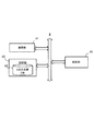
- FIG. 1 is a schematic configuration of an advanced map system according to the present embodiment.
- the advanced map system includes an in-vehicle device 1 that moves together with a vehicle, a lidar (Lider: Light Illuminated Detection And Ranging) 2 that is controlled by the in-vehicle device 1, and features (natural products) around the road. And a server device 4 that stores a three-dimensional point group DB 43 that is a database of three-dimensional point groups that discretely constitute the surface of the object.
- the advanced map system performs high-precision vehicle position estimation by matching the point cloud measured by the lidar 2 with the point cloud registered in the three-dimensional point cloud DB 43.
- the in-vehicle device 1 is electrically connected to the lidar 2 and performs light emission control of the lidar 2 for detecting the feature.
- the in-vehicle device 1 stores in advance information related to the characteristics of the rider 2 (also referred to as “rider characteristic information IL”).
- the in-vehicle device 1 then receives a request signal (“point group”) including the vehicle position predicted by the output of a measurement unit such as a GPS receiver described later (also referred to as “predicted vehicle position Ppr”) and the rider characteristic information IL.
- the information request signal Sr is also transmitted to the server device 4.
- the in-vehicle device 1 receives from the server device 4 point group information (also referred to as “map point group information Da”) extracted from the three-dimensional point group DB 43 based on the rider characteristic information IL and the predicted host vehicle position Ppr. Receive. Then, the in-vehicle device 1 is based on the point cloud information output from the lidar 2 (also referred to as “measurement point cloud information Db”) and the map point cloud information Da received from the server device 4, and the predicted host vehicle position Ppr. And an estimated value of the vehicle position obtained by correcting the predicted vehicle position Ppr based on the error is calculated.
- the in-vehicle device 1 is an example of the “terminal device” in the present invention.
- the lidar 2 emits a pulse laser in a predetermined angle range in the horizontal direction and the vertical direction, thereby discretely measuring the distance to an object existing in the outside world, and a three-dimensional point indicating the position of the object Group information is generated as measurement point group information Db.
- the lidar 2 includes an emitting unit that emits laser light while changing the irradiation direction, a light receiving unit that receives reflected light (scattered light) of the irradiated laser light, and a point group based on a light reception signal output from the light receiving unit. And an output unit for outputting information.
- the point cloud information is generated based on the irradiation direction corresponding to the laser beam received by the light receiving unit and the response delay time of the laser beam specified based on the above-described received light signal.
- the lidar 2 may generate two-dimensional point group information by emitting a pulse laser only in a predetermined angular range in the horizontal direction without scanning in the vertical direction. Then, the rider 2 supplies the generated measurement point group information Db to the in-vehicle device 1.
- the measurement point group information Db is represented by a relative coordinate system (also simply referred to as “relative coordinate system”) with the vehicle-mounted device 1 as a reference.
- the lidar 2 is an example of the “external field detection device” in the present invention.
- the server device 4 stores map data including the three-dimensional point cloud DB 43.
- the server device 4 receives the point cloud information request signal Sr from the vehicle-mounted device 1, the server device 4 measures the space measured by the lidar 2 based on the rider characteristic information IL and the predicted vehicle position Ppr included in the point cloud information request signal Sr (
- the map point cloud information Da which is point cloud information indicating the position in the scan space, is extracted from the three-dimensional point cloud DB 43 and transmitted to the in-vehicle device 1.
- the server device 4 is an example of the “information output device” in the present invention.
- the scan target space is an example of the “detection range” in the present invention, and includes not only a three-dimensional space but also a two-dimensional space.
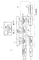
- FIG. 2A is a block diagram showing a functional configuration of the in-vehicle device 1.
- the in-vehicle device 1 mainly includes a communication unit 11, a storage unit 12, a sensor unit 13, an input unit 14, a control unit 15, and an output unit 16. Each of these elements is connected to each other via a bus line.
- the communication unit 11 performs data communication with the server device 4 based on the control of the control unit 15.
- the storage unit 12 stores a program executed by the control unit 15 and information necessary for the control unit 15 to execute a predetermined process.
- the storage unit 12 stores the rider characteristic information IL in advance.
- the lidar characteristic information IL is an example of “characteristic information” in the present invention.
- FIG. 2B is an example of the data structure of the lidar characteristic information IL.
- the lidar characteristic information IL includes installation height information and scan range information.
- the installation height information is information indicating the relative installation height of the rider 2 with respect to the vehicle on which the rider 2 is disposed, and for example, indicates the height with respect to the horizontal plane when the vehicle exists on the horizontal plane.
- the scan range information is information indicating the relative measurable range of the rider 2 with respect to the vehicle. For example, the horizontal angle range and the vertical of the scan by the rider 2 when a predetermined direction (for example, the traveling direction of the vehicle) is used as a reference.
- the angle range the measurable distance of the lidar 2 (that is, the scanning distance), the number of irradiation layers indicating the number of layers of the scan surface irradiated with the laser of the lidar 2 or the number of laser transmission / reception sensors (number of sensors) of the lidar 2; And an interlayer angle indicating an angle between adjacent irradiation surfaces.
- the scan range information is replaced by the number of layers on the scan plane (that is, the number of scan lines) instead of the vertical angle range described above. May also be included.
- the storage unit 12 stores, in advance, the installation height information, the scan range information, and the like that are measured in advance based on, for example, experiments as lidar characteristic information IL.
- the sensor unit 13 is a sensor that detects the state of the vehicle, and includes a GPS receiver 32, an IMU (Internal Measurement Unit) 33, and the like.
- the control unit 15 calculates the predicted host vehicle position Ppr based on the output of the sensor unit 13.
- the sensor unit 13 is an example of the “measurement unit” in the present invention.
- the input unit 14 is a button operated by the user, a touch panel, a remote controller, a voice input device, and the like
- the output unit 16 is, for example, a display or a speaker that performs output based on the control of the control unit 15.
- the control unit 15 includes a CPU that executes a program and controls the entire vehicle-mounted device 1.
- the control unit 15 for example, point group information including the predicted host vehicle position Ppr calculated based on the output of the sensor unit 13 and the lidar characteristic information IL stored in the storage unit 12 at predetermined time intervals.
- the request signal Sr is transmitted to the server device 4 by the communication unit 11.
- the control unit 15 detects the point group indicated by the map point group information Da and the measurement point group output by the lidar 2.
- control unit 15 calculates the predicted own vehicle position Ppr corrected by the error indicated by the error information dP as an estimated value of the own vehicle position.
- the control unit 15 is an example of the “position prediction unit”, “transmission unit”, “reception unit”, and “estimation unit” in the present invention.
- FIG. 3 is a block diagram showing a functional configuration of the server device 4.
- the server device 4 mainly includes a communication unit 41, a storage unit 42, and a control unit 45. Each of these elements is connected to each other via a bus line.
- the communication unit 41 performs data communication with the in-vehicle device 1 based on the control of the control unit 45.
- the storage unit 42 stores a program executed by the control unit 45 and information necessary for the control unit 45 to execute a predetermined process.
- the storage unit 42 stores map data including the three-dimensional point cloud DB 43.
- the three-dimensional point group DB 43 is a database of three-dimensional point group information that forms the surface of a feature existing around each road registered in the map data.
- Each point group registered in the three-dimensional point group DB 43 is represented by, for example, three-dimensional coordinates of latitude / longitude and height (for example, altitude).
- the coordinate system of each point group registered in the three-dimensional point group DB 43 is also referred to as “absolute coordinate system”.
- the point group information registered in the three-dimensional point group DB 43 may be generated from point group information output by a lidar scanned in the horizontal direction and the vertical direction.
- the point cloud information registered in the 3D point cloud DB 43 is a 3D image indicating each feature generated based on the point cloud information output by the lidar, the position information and the shape information of the feature included in the map data, and the like. Point cloud information.
- Each point group information registered in the three-dimensional point group DB 43 is an example of “feature information” in the present invention.
- the control unit 45 includes a CPU that executes a program and the like, and controls the entire server device 4.
- the control unit 45 when the communication unit 41 receives the point group information request signal Sr from the in-vehicle device 1, the control unit 45 includes the predicted host vehicle position Ppr and the rider characteristic information IL included in the point group information request signal Sr. Based on this, the space to be scanned by the lidar 2 is specified. And the control part 45 extracts the map point cloud information Da which shows the point cloud which becomes in the specified scanning object space from 3D point cloud DB43, and the vehicle unit 1 uses the extracted map point cloud information Da by the communication part 41. Send to.
- the control unit 45 is an example of the “acquiring unit”, “output unit” in the present invention, and a computer that executes the program in the present invention.
- FIG. 4 is a block diagram showing a functional configuration of the in-vehicle device 1.
- the control unit 15 of the in-vehicle device 1 functionally includes a predicted host vehicle position acquisition unit 51, a lidar characteristic information extraction unit 52, a map point group information acquisition unit 53, and a measurement point group.
- the information acquisition unit 54, the matching unit 55, and the own vehicle position estimation unit 56 are included.
- the predicted vehicle position acquisition unit 51 predicts the two-dimensional or three-dimensional position including the current latitude and longitude and the traveling direction of the vehicle based on the outputs of the GPS receiver 32 and the IMU 33. Then, the predicted host vehicle position acquisition unit 51 includes the predicted position information as the predicted host vehicle position Ppr in the point cloud information request signal Sr, and transmits it to the server device 4 by the communication unit 11.
- the rider characteristic information extraction unit 52 extracts the rider characteristic information IL stored in the storage unit 12, includes the extracted rider characteristic information IL in the point group information request signal Sr, and transmits the point group information request signal Sr to the server device 4.
- the map point cloud information acquisition unit 53 receives the map point cloud information Da transmitted by the server device 4 as a response to the point cloud information request signal Sr by the communication unit 11. Then, the map point group information acquisition unit 53 supplies the received map point group information Da to the matching unit 55.
- the measurement point group information acquisition unit 54 acquires the measurement point group information Db output from the lidar 2 and supplies it to the matching unit 55. In this case, since the map point group information acquisition unit 53 receives only the minimum map point group information Da necessary for matching by the matching unit 55, the communication capacity and the necessary storage capacity can be suitably reduced. The processing load of the matching process with the measurement point group information Db can be suitably reduced.
- the matching unit 55 performs matching (position) between the point cloud indicated by the measurement point cloud information Db acquired from the measurement point cloud information acquisition unit 54 and the point cloud indicated by the map point cloud information Da acquired from the map point cloud information acquisition unit 53. Error information dP is generated.
- the matching unit 55 first acquires the predicted vehicle position Ppr obtained from the predicted vehicle position acquisition unit 51 by using the measurement point cloud information Db represented by the relative coordinate system based on the position and the traveling direction of the vehicle-mounted device 1. Based on, convert to absolute coordinate system.
- the matching unit 55 converts the point cloud indicated by the measurement point cloud information Db converted into the absolute coordinate system and the point cloud indicated by the map point cloud information Da expressed by the absolute coordinate system into an ICP (Iterative Closest Point) or the like.
- the matching is performed using a known matching method.
- the matching unit 55 calculates a vector amount and a rotation angle indicating a displacement necessary for aligning the point group of the measurement point group information Db converted into the absolute coordinate system with the point group of the corresponding map point group information Da.
- the calculated information is supplied to the vehicle position estimation unit 56 as error information dP.
- a specific example of the matching unit 55 will be described with reference to FIGS. 5 and 6.
- the own vehicle position estimation unit 56 acquires the error information dP and the predicted own vehicle position Ppr from the matching unit 55, and estimates the own vehicle position by reflecting the position and orientation deviation indicated by the error information dP in the predicted own vehicle position Ppr. Calculate the value.
- the estimated value of the vehicle position calculated by the vehicle position estimation unit 56 is used for various controls such as automatic driving and route guidance, for example.
- FIG. 5A is a diagram showing a state in which the laser output from the lidar 2 is applied to the features 60 to 62 such as buildings around the vehicle on which the vehicle-mounted device 1 is mounted.
- FIG. 5B is a diagram in which a point group serving as a laser irradiation position in FIG. 5A is extracted.
- a case where the lidar 2 scans only in the horizontal direction is shown.
- the measurement point group information acquisition unit 54 acquires measurement point group information Db corresponding to the point group of the surface positions of the features 60 to 62 existing at the same height as the lidar 2 from the lidar 2, and the matching unit 55 converts the measurement point group information Db acquired by the measurement point group information acquisition unit 54 into three-dimensional coordinates in the absolute coordinate system using the predicted vehicle position Ppr.
- FIG. 6 (A) is a diagram visualizing the point cloud around the vehicle registered in the three-dimensional point cloud DB 43.
- the three-dimensional point cloud DB 43 stores the point cloud information of the three-dimensional surface of the features 60 to 62 and the point cloud information of the edge of the road. Then, when the server device 4 receives the point cloud information request signal Sr, the predicted vehicle position Ppr included in the point cloud information request signal Sr, and the rider characteristic information IL including the installation height information and the scan range information, Based on the above, the scan target space of the lidar 2 is specified, and the map point group information Da indicating the point group in the space is extracted from the three-dimensional point group DB 43.
- FIG. 6B is a diagram in which a point cloud corresponding to the map point cloud information Da transmitted to the vehicle-mounted device 1 is extracted from the point cloud shown in FIG.
- the server device 4 specifies the scan target space by the lidar 2 based on the rider characteristic information IL and the predicted host vehicle position Ppr, and extracts a point group in the specified scan target space.
- the server device 4 recognizes the height of the irradiation surface of the lidar 2 based on the installation height information of the lidar characteristic information IL, and the recognized height and the height within a predetermined distance.
- a point cloud is extracted.
- the server device 4 may determine the height range of the point group extracted from the three-dimensional point group DB 43 according to the range. In this case, the server device 4 may make the vertical scan range included in the scan range information the same as the height range of the point group extracted from the three-dimensional point group DB 43, and the rider 2 due to the posture change of the traveling vehicle.
- the height range of the point group extracted from the three-dimensional point group DB 43 may be made somewhat larger than the vertical scan range included in the scan range information.
- the server device 4 recognizes the scan range on the horizontal plane of the rider 2 on the horizontal plane based on the scan range information of the rider characteristic information IL and the predicted vehicle position Ppr. A point cloud of the features 60 to 62 existing in the scan range is extracted.
- the server device 4 extracts a point group corresponding to the number of irradiation layers based on information indicating the number of irradiation layers (or the number of laser transmission / reception sensors of the lidar 2) included in the scan range information of the lidar characteristic information IL. May be.
- the server device 4 determines the height range of the point group extracted from the three-dimensional point cloud DB 43 based on the information indicating the angle between the irradiation layers included in the scan range information. May be.
- the server device 4 adds the altitude of the road surface on which the vehicle exists to the installation height information to irradiate the lidar 2. Calculate the elevation of the surface.
- the predicted host vehicle position Ppr included in the point cloud information request signal Sr includes information on the altitude of the vehicle based on the output of the GPS receiver 32 or the like. Based on the information, the altitude of the road surface on which the vehicle is present is recognized.
- the server device 4 recognizes the altitude of the road surface on which the vehicle is present based on the altitude information when the road data corresponding to the road on which the vehicle is present includes the altitude information.
- the matching unit 55 converts the point group shown in FIG. 5B (that is, the point group indicated by the measurement point group information Db) converted into the absolute coordinate system and the point group shown in FIG. 6B (that is, map points). Alignment with the point group indicated by the group information Da) is performed. Then, the matching unit 55 generates error information dP corresponding to the vector amount and the rotation angle indicating the deviation of the point group shown in FIG. 5B converted from the point group shown in FIG. 5B with respect to the point group shown in FIG. 6B. To do.
- the in-vehicle device 1 receives only the minimum map point group information Da necessary for matching by the matching unit 55 from the server device 4, so that the communication capacity and the necessary storage capacity are reduced.
- the processing load of the matching process can be suitably reduced.
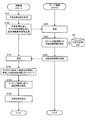
- FIG. 7 is a flowchart showing the procedure of the vehicle position estimation process in the present embodiment.
- the in-vehicle device 1 repeatedly executes the flowchart shown in FIG.
- the in-vehicle device 1 acquires the predicted own vehicle position Ppr indicating the current latitude, longitude, traveling direction of the vehicle, and the like based on the outputs of the GPS receiver 32 and the IMU 33 (step S101).
- the predicted vehicle position Ppr may be information including the current altitude measured by the GPS receiver 32 or the like.
- the vehicle equipment 1 transmits the point cloud information request
- the server device 4 receives the point cloud information request signal Sr transmitted from the vehicle-mounted device 1 (step S201). Then, the server device 4 recognizes the scan target space to be scanned by the lidar 2 in the absolute coordinate system based on the predicted host vehicle position Ppr and the lidar characteristic information IL included in the point cloud information request signal Sr, and Map point group information Da indicating the point group in the scan target space is extracted from the three-dimensional point group DB 43 (step S202). And the server apparatus 4 transmits the map point cloud information Da extracted from 3D point cloud DB43 to the vehicle equipment 1 (step S203).
- the in-vehicle device 1 receives the map point cloud information Da from the server device 4 (step S103).
- the in-vehicle device 1 performs matching using the measurement point group information Db acquired from the lidar 2 and the received map point group information Da (step S104).
- the vehicle equipment 1 calculates error information dP based on a matching result (step S105).
- the vehicle equipment 1 calculates the estimated value of the own vehicle position by correcting the predicted own vehicle position Ppr calculated in step S101 based on the calculated error information dP (step S106).
- the server apparatus 4 stores the three-dimensional point cloud DB 43 and receives the point cloud information request signal Sr including the rider characteristic information IL regarding the characteristics of the rider 2 and the predicted own vehicle position Ppr.
- the server device 4 extracts map point group information Da corresponding to the point group in the specified scan target space from the three-dimensional point group DB 43 and transmits it to the in-vehicle device 1.
- the in-vehicle device 1 since the in-vehicle device 1 receives only the minimum map point group information Da necessary for matching, the communication capacity and the necessary storage capacity can be suitably reduced, and the measurement point group information Db can be reduced.
- the processing load of the matching process can be suitably reduced.
- the server device 4 may be composed of a plurality of servers.
- a server that stores the three-dimensional point cloud DB 43 and a server that executes the processes of steps S201 to S203 in FIG. 7 may be configured separately.
- each server receives the information required in order to perform the process allocated previously from another server, and performs a required process.
Abstract
This server device 4: stores a three-dimensional point group DB 43; and when receiving, from a vehicle-mounted device 1, a point group information request signal Sr including rider characteristic information IL on characteristics of a rider 2 and a predicted present-vehicle location Ppr, specifies a scan-target space by the rider 2. Then, the server device 4 extracts, from the three-dimensional point group DB 43, map point group information Da corresponding to a point group within the specified scan-target space, and transmits the same to the vehicle-mounted device 1.
Description
本発明は、情報を出力する技術に関する。
The present invention relates to a technology for outputting information.
従来から、外界センサを用いて現在位置を高精度に推定する技術が知られている。例えば、特許文献1には、移動体周辺のランドマークを観測する外界センサの観測結果と、環境全域におけるランドマークに関する情報を収めた大域地図とのマッチングを行うことで、自己位置を推定する技術が開示されている。
Conventionally, a technique for estimating the current position with high accuracy using an external sensor is known. For example, Patent Document 1 discloses a technique for estimating a self-position by matching an observation result of an external sensor that observes landmarks around a moving body and a global map that contains information about landmarks in the entire environment. Is disclosed.
自動運転における自己位置推定の場合、特許文献1に記載のような大域地図のデータ容量は膨大となるため、サーバ装置が大域地図を管理し、移動体側の端末が適宜サーバ装置から自己位置周辺のランドマークの情報を取得することになる。この場合、移動体側の端末は、周辺に存在するランドマークの情報を全てサーバ装置から取得することになると、通信量が多くなってしまい、自己位置推定に必要な情報を選定する処理負荷等も増加するという問題がある。
In the case of self-position estimation in automatic driving, the data capacity of the global map as described in Patent Document 1 is enormous, so the server device manages the global map, and the mobile-side terminal appropriately Landmark information is acquired. In this case, if the mobile terminal acquires all the landmark information existing in the vicinity from the server device, the amount of communication increases, and the processing load for selecting information necessary for self-position estimation also increases. There is a problem of increasing.
本発明は、例えば、上記のような課題を解決するためになされたものであり、出力させるデータ量を好適に低減させることが可能な情報出力装置を提供することを主な目的とする。
The present invention has been made in order to solve the above-described problems, for example, and has as its main object to provide an information output device capable of suitably reducing the amount of data to be output.
請求項に記載の発明は、情報出力装置であって、移動体に配置された外界検出装置の特性に関する特性情報を取得する取得部と、前記特性情報に基づいて、記憶部に記憶された地物を示す地物情報から前記地物情報の一部を抽出して出力する出力部と、を備える。
The invention described in the claims is an information output device, and an acquisition unit that acquires characteristic information about characteristics of an external field detection device arranged on a moving body, and a ground that is stored in a storage unit based on the characteristic information. An output unit that extracts and outputs a part of the feature information from the feature information indicating the object.
また、請求項に記載の発明は、外界検出装置が配置された移動体と共に移動する端末装置であって、前記外界検出装置の特性に関する特性情報を記憶する記憶部と、前記特性情報を請求項1~4のいずれか一項に記載の情報出力装置に送信する送信部と、前記情報出力装置から地物情報を受信する受信部と、前記地物情報と、前記外界検出装置の検出情報とに基づき現在位置を推定する推定部と、を備える。
The invention described in the claims is a terminal device that moves together with a moving body in which an external field detection device is arranged, and includes a storage unit that stores characteristic information related to characteristics of the external field detection device, and the characteristic information. A transmission unit that transmits to the information output device according to any one of 1 to 4, a reception unit that receives feature information from the information output device, the feature information, and detection information of the external field detection device, And an estimation unit for estimating the current position based on.
また、請求項に記載の発明は、情報出力装置が実行する制御方法であって、移動体に配置された外界検出装置の特性に関する特性情報を取得する取得工程と、前記特性情報に基づいて、記憶部に記憶された地物を示す地物情報から前記地物情報の一部を抽出して出力する出力工程と、を有する。
The invention described in the claims is a control method executed by the information output device, based on the acquisition step of acquiring characteristic information about the characteristic of the external field detection device arranged on the moving body, and the characteristic information, And an output step of extracting and outputting a part of the feature information from the feature information indicating the feature stored in the storage unit.
また、請求項に記載の発明は、コンピュータが実行するプログラムであって、移動体に配置された外界検出装置の特性に関する特性情報を取得する取得部と、前記特性情報に基づいて、記憶部に記憶された地物を示す地物情報から前記地物情報の一部を抽出して出力する出力部として前記コンピュータを機能させる。
The invention described in the claims is a program executed by a computer, and an acquisition unit that acquires characteristic information about characteristics of an external field detection device arranged in a moving body, and a storage unit based on the characteristic information The computer is caused to function as an output unit that extracts and outputs a part of the feature information from the feature information indicating the stored feature.
本発明の好適な実施形態によれば、情報出力装置であって、移動体に配置された外界検出装置の特性に関する特性情報を取得する取得部と、前記特性情報に基づいて、記憶部に記憶された地物を示す地物情報から前記地物情報の一部を抽出して出力する出力部と、を備える。ここで、「地物情報の一部を抽出」とは、記憶部に記憶された地物情報から特性情報に基づいてその一部を抽出することを指す。よって、所定個数の地物の各々に対する地物情報が記憶部に記憶されている場合に、全体が該当する地物に対する地物情報をそのまま抽出する態様や、一部が該当する地物に対する地物情報の該当部分を切り出して抽出する態様も含まれる。この実施形態によれば、情報出力装置は、外界検出装置の特性に関する特性情報に基づいて、出力すべき地物情報を好適に限定することができる。
According to a preferred embodiment of the present invention, the information output device is an acquisition unit that acquires characteristic information relating to characteristics of an external field detection device arranged on a moving body, and stores in the storage unit based on the characteristic information. An output unit that extracts and outputs a part of the feature information from the feature information indicating the feature that has been generated. Here, “extracting part of the feature information” refers to extracting a part of the feature information from the feature information stored in the storage unit based on the characteristic information. Therefore, when the feature information for each of the predetermined number of features is stored in the storage unit, the feature information for the feature corresponding to the whole is extracted as it is, or the feature for the feature to which a part is applicable. The aspect which cuts out and extracts the applicable part of physical information is also contained. According to this embodiment, the information output device can suitably limit the feature information to be output based on the characteristic information related to the characteristics of the external field detection device.
上記情報出力装置の一態様では、前記出力部は、前記特性情報に基づき前記外界検出装置の検出範囲を特定し、当該検出範囲内に存在する地物の地物情報を抽出して出力する。この態様により、情報出力装置は、好適に外界検出装置の検出範囲内の地物情報を出力し、外界検出装置の検出情報とのマッチング等に活用させることができる。
In one aspect of the information output device, the output unit specifies a detection range of the external field detection device based on the characteristic information, and extracts and outputs feature information of features existing in the detection range. According to this aspect, the information output device can preferably output the feature information within the detection range of the external detection device, and can be used for matching with the detection information of the external detection device.
上記情報出力装置の他の一態様では、前記特性情報には、前記外界検出装置の設置位置の高さに関する情報、又は、水平方向又は/及び垂直方向において前記外界検出装置が検出を行う範囲に関する情報が含まれる。この態様により、情報出力装置は、好適に外界検出装置の検出範囲を特定し、抽出すべき地物情報を決定することができる。
In another aspect of the information output device, the characteristic information relates to information related to a height of an installation position of the external environment detection device, or a range in which the external environment detection device performs detection in the horizontal direction and / or the vertical direction. Contains information. According to this aspect, the information output device can preferably specify the detection range of the external detection device and determine the feature information to be extracted.
上記情報出力装置の他の一態様では、前記取得部は、前記外界検出装置の検出情報を受信する端末装置から前記特性情報及び前記移動体の位置情報を受信し、前記出力部は、前記特性情報及び前記位置情報に基づき抽出した前記地物情報を前記端末装置へ送信する。この態様により、情報出力装置は、外界検出装置の検出情報と当該検出情報に対応する地物情報とを好適に端末装置に取得させることができる。
In another aspect of the information output device, the acquisition unit receives the characteristic information and the position information of the moving body from a terminal device that receives detection information of the external environment detection device, and the output unit receives the characteristic The feature information extracted based on the information and the position information is transmitted to the terminal device. According to this aspect, the information output device can cause the terminal device to suitably acquire the detection information of the external environment detection device and the feature information corresponding to the detection information.
本発明の他の好適な実施形態によれば、外界検出装置が配置された移動体と共に移動する端末装置であって、前記外界検出装置の特性に関する特性情報を記憶する記憶部と、前記特性情報を上記いずれか記載の情報出力装置に送信する送信部と、前記情報出力装置から地物情報を受信する受信部と、前記地物情報と、前記外界検出装置の検出情報とに基づき現在位置を推定する推定部と、を備える。この態様によれば、端末装置は、地物情報を記憶する情報出力装置から現在位置の推定に必要な最小限の地物情報を受信し、現在位置の推定を効率的に行うことができる。
According to another preferred embodiment of the present invention, a terminal device that moves together with a mobile object in which an external field detection device is arranged, a storage unit that stores characteristic information relating to characteristics of the external field detection device, and the characteristic information Based on the transmission unit that transmits the information to the information output device, the reception unit that receives the feature information from the information output device, the feature information, and the detection information of the external field detection device. An estimation unit for estimation. According to this aspect, the terminal device can receive the minimum feature information necessary for estimating the current position from the information output device that stores the feature information, and can efficiently estimate the current position.
上記端末装置の一態様では、前記検出情報及び前記地物情報は、点群情報であり、前記推定部は、前記検出情報が示す点群と、当該点群に対応する前記地物情報が示す点群との位置の誤差に基づき、前記現在位置を推定する。この態様により、端末装置は、情報出力装置が予め記憶した地物の点群情報を基準として、外界検出装置が出力する点群情報から正確に自己位置を推定することが可能となる。
In one aspect of the terminal device, the detection information and the feature information are point cloud information, and the estimation unit indicates the point cloud indicated by the detection information and the feature information corresponding to the point cloud. The current position is estimated based on a position error with respect to the point cloud. According to this aspect, the terminal device can accurately estimate its own position from the point cloud information output by the external field detection device with reference to the point cloud information of the feature stored in advance by the information output device.
上記端末装置の他の一態様では、端末装置は、測定部の出力に基づく現在位置の予測値を取得する位置予測部をさらに備え、前記推定部は、前記地物情報と前記検出情報とに基づき前記予測値を補正することで、前記現在位置の推定値を算出する。この態様により、端末装置は、測定部が測定した現在位置よりも高精度な現在位置を取得することができる。
In another aspect of the terminal device, the terminal device further includes a position prediction unit that obtains a predicted value of the current position based on the output of the measurement unit, and the estimation unit includes the feature information and the detection information. The estimated value of the current position is calculated by correcting the predicted value based on the calculated value. According to this aspect, the terminal device can acquire the current position with higher accuracy than the current position measured by the measurement unit.
本発明の他の好適な実施形態によれば、情報出力装置が実行する制御方法であって、移動体に配置された外界検出装置の特性に関する特性情報を取得する取得工程と、前記特性情報に基づいて、記憶部に記憶された地物を示す地物情報から前記地物情報の一部を抽出して出力する出力工程と、を有する。情報出力装置は、この制御方法を実行することで、外界検出装置の特性に関する特性情報に基づいて、出力すべき地物情報を好適に限定することができる。
According to another preferred embodiment of the present invention, there is provided a control method executed by the information output device, the acquisition step of acquiring characteristic information related to the characteristics of the external field detection device arranged on the moving body, and the characteristic information And an output step for extracting and outputting a part of the feature information from the feature information indicating the feature stored in the storage unit. By executing this control method, the information output device can suitably limit the feature information to be output based on the characteristic information related to the characteristics of the external environment detection device.
本発明の他の好適な実施形態によれば、コンピュータが実行するプログラムであって、移動体に配置された外界検出装置の特性に関する特性情報を取得する取得部と、前記特性情報に基づいて、記憶部に記憶された地物を示す地物情報から前記地物情報の一部を抽出して出力する出力部として前記コンピュータを機能させる。コンピュータは、このプログラムを実行することで、外界検出装置の特性に関する特性情報に基づいて、出力すべき地物情報を好適に限定することができる。好適には、上記プログラムは、記憶媒体に記憶される。
According to another preferred embodiment of the present invention, a program executed by a computer, based on the acquisition unit that acquires characteristic information about the characteristic of the external field detection device arranged in the moving body, and the characteristic information, The computer is caused to function as an output unit that extracts and outputs a part of the feature information from the feature information indicating the feature stored in the storage unit. By executing this program, the computer can suitably limit the feature information to be output based on the characteristic information relating to the characteristics of the external detection device. Preferably, the program is stored in a storage medium.
以下、図面を参照して本発明の好適な実施例について説明する。実施例において、点群とは、3次元位置が特定される点の集合体を指し、3次元点群とは、3次元に(即ち空間的に)分布する点群を指すものとする。
Hereinafter, preferred embodiments of the present invention will be described with reference to the drawings. In the embodiment, the point group refers to an aggregate of points whose three-dimensional positions are specified, and the three-dimensional point group refers to a point group distributed three-dimensionally (that is, spatially).
[高度化地図システムの概要]
図1は、本実施例に係る高度化地図システムの概略構成である。高度化地図システムは、車両と共に移動する車載機1と、車載機1により制御されるライダ(Lidar:Light Detection and Ranging、または、Laser Illuminated Detection And Ranging)2と、道路周辺の地物(天然物及び人工物の両方を含む。)の表面を離散的に構成する3次元点群のデータベースである3次元点群DB43を記憶するサーバ装置4とを備える。そして、高度化地図システムは、ライダ2により計測された点群と、3次元点群DB43に登録された点群とのマッチングを行うことにより、高精度な自車位置推定を行う。 [Outline of advanced map system]
FIG. 1 is a schematic configuration of an advanced map system according to the present embodiment. The advanced map system includes an in-vehicle device 1 that moves together with a vehicle, a lidar (Lider: Light Illuminated Detection And Ranging) 2 that is controlled by the in-vehicle device 1, and features (natural products) around the road. And a server device 4 that stores a three-dimensional point group DB 43 that is a database of three-dimensional point groups that discretely constitute the surface of the object. The advanced map system performs high-precision vehicle position estimation by matching the point cloud measured by the lidar 2 with the point cloud registered in the three-dimensional point cloud DB 43.
図1は、本実施例に係る高度化地図システムの概略構成である。高度化地図システムは、車両と共に移動する車載機1と、車載機1により制御されるライダ(Lidar:Light Detection and Ranging、または、Laser Illuminated Detection And Ranging)2と、道路周辺の地物(天然物及び人工物の両方を含む。)の表面を離散的に構成する3次元点群のデータベースである3次元点群DB43を記憶するサーバ装置4とを備える。そして、高度化地図システムは、ライダ2により計測された点群と、3次元点群DB43に登録された点群とのマッチングを行うことにより、高精度な自車位置推定を行う。 [Outline of advanced map system]
FIG. 1 is a schematic configuration of an advanced map system according to the present embodiment. The advanced map system includes an in-
車載機1は、ライダ2と電気的に接続され、地物を検知するためのライダ2の光の出射制御を行う。本実施例では、車載機1は、ライダ2の特性に関する情報(「ライダ特性情報IL」とも呼ぶ。)を予め記憶する。そして、車載機1は、後述するGPS受信機等の測定部の出力により予測した自車位置(「予測自車位置Ppr」とも呼ぶ。)とライダ特性情報ILとを含む要求信号(「点群情報要求信号Sr」とも呼ぶ。)をサーバ装置4へ送信する。これにより、車載機1は、ライダ特性情報IL及び予測自車位置Pprに基づき3次元点群DB43から抽出された点群情報(「地図点群情報Da」とも呼ぶ。)を、サーバ装置4から受信する。そして、車載機1は、ライダ2から出力された点群情報(「計測点群情報Db」とも呼ぶ。)と、サーバ装置4から受信した地図点群情報Daとに基づき、予測自車位置Pprの誤差を算出し、当該誤差により予測自車位置Pprを補正した自車位置の推定値を算出する。車載機1は、本発明における「端末装置」の一例である。
The in-vehicle device 1 is electrically connected to the lidar 2 and performs light emission control of the lidar 2 for detecting the feature. In the present embodiment, the in-vehicle device 1 stores in advance information related to the characteristics of the rider 2 (also referred to as “rider characteristic information IL”). The in-vehicle device 1 then receives a request signal (“point group”) including the vehicle position predicted by the output of a measurement unit such as a GPS receiver described later (also referred to as “predicted vehicle position Ppr”) and the rider characteristic information IL. The information request signal Sr ”is also transmitted to the server device 4. Thereby, the in-vehicle device 1 receives from the server device 4 point group information (also referred to as “map point group information Da”) extracted from the three-dimensional point group DB 43 based on the rider characteristic information IL and the predicted host vehicle position Ppr. Receive. Then, the in-vehicle device 1 is based on the point cloud information output from the lidar 2 (also referred to as “measurement point cloud information Db”) and the map point cloud information Da received from the server device 4, and the predicted host vehicle position Ppr. And an estimated value of the vehicle position obtained by correcting the predicted vehicle position Ppr based on the error is calculated. The in-vehicle device 1 is an example of the “terminal device” in the present invention.
ライダ2は、水平方向および垂直方向の所定の角度範囲に対してパルスレーザを出射することで、外界に存在する物体までの距離を離散的に測定し、当該物体の位置を示す3次元の点群情報を計測点群情報Dbとして生成する。この場合、ライダ2は、照射方向を変えながらレーザ光を出射する出射部と、照射したレーザ光の反射光(散乱光)を受光する受光部と、受光部が出力する受光信号に基づく点群情報を出力する出力部とを有する。点群情報は、受光部が受光したレーザ光に対応する照射方向と、上述の受光信号に基づき特定される当該レーザ光の応答遅延時間とに基づき生成される。なお、ライダ2は、垂直方向へは走査することなく水平方向の所定角度範囲のみに対してパルスレーザを出射して2次元の点群情報を生成するものであってもよい。そして、ライダ2は、生成した計測点群情報Dbを車載機1へ供給する。計測点群情報Dbは、車載機1を基準とした相対的な座標系(単に「相対座標系」とも呼ぶ。)により表される。ライダ2は、本発明における「外界検出装置」の一例である。
The lidar 2 emits a pulse laser in a predetermined angle range in the horizontal direction and the vertical direction, thereby discretely measuring the distance to an object existing in the outside world, and a three-dimensional point indicating the position of the object Group information is generated as measurement point group information Db. In this case, the lidar 2 includes an emitting unit that emits laser light while changing the irradiation direction, a light receiving unit that receives reflected light (scattered light) of the irradiated laser light, and a point group based on a light reception signal output from the light receiving unit. And an output unit for outputting information. The point cloud information is generated based on the irradiation direction corresponding to the laser beam received by the light receiving unit and the response delay time of the laser beam specified based on the above-described received light signal. Note that the lidar 2 may generate two-dimensional point group information by emitting a pulse laser only in a predetermined angular range in the horizontal direction without scanning in the vertical direction. Then, the rider 2 supplies the generated measurement point group information Db to the in-vehicle device 1. The measurement point group information Db is represented by a relative coordinate system (also simply referred to as “relative coordinate system”) with the vehicle-mounted device 1 as a reference. The lidar 2 is an example of the “external field detection device” in the present invention.
サーバ装置4は、3次元点群DB43を含む地図データを記憶する。サーバ装置4は、車載機1から点群情報要求信号Srを受信した場合に、点群情報要求信号Srに含まれるライダ特性情報IL及び予測自車位置Pprに基づき、ライダ2が計測する空間(「スキャン対象空間」とも呼ぶ。)を認識し、当該スキャン対象空間内の位置を指し示す点群の情報である地図点群情報Daを3次元点群DB43から抽出して車載機1へ送信する。サーバ装置4は、本発明における「情報出力装置」の一例である。また、スキャン対象空間は、本発明における「検出範囲」の一例であり、3次元空間に限らず2次元空間の場合も含む。
The server device 4 stores map data including the three-dimensional point cloud DB 43. When the server device 4 receives the point cloud information request signal Sr from the vehicle-mounted device 1, the server device 4 measures the space measured by the lidar 2 based on the rider characteristic information IL and the predicted vehicle position Ppr included in the point cloud information request signal Sr ( The map point cloud information Da, which is point cloud information indicating the position in the scan space, is extracted from the three-dimensional point cloud DB 43 and transmitted to the in-vehicle device 1. The server device 4 is an example of the “information output device” in the present invention. The scan target space is an example of the “detection range” in the present invention, and includes not only a three-dimensional space but also a two-dimensional space.
図2(A)は、車載機1の機能的構成を示すブロック図である。車載機1は、主に、通信部11と、記憶部12と、センサ部13と、入力部14と、制御部15と、出力部16とを有する。これらの各要素は、バスラインを介して相互に接続されている。
FIG. 2A is a block diagram showing a functional configuration of the in-vehicle device 1. The in-vehicle device 1 mainly includes a communication unit 11, a storage unit 12, a sensor unit 13, an input unit 14, a control unit 15, and an output unit 16. Each of these elements is connected to each other via a bus line.
通信部11は、制御部15の制御に基づき、サーバ装置4とデータ通信を行う。
The communication unit 11 performs data communication with the server device 4 based on the control of the control unit 15.
記憶部12は、制御部15が実行するプログラムや、制御部15が所定の処理を実行するのに必要な情報を記憶する。また、本実施例では、記憶部12は、ライダ特性情報ILを予め記憶しておく。ライダ特性情報ILは、本発明における「特性情報」の一例である。
The storage unit 12 stores a program executed by the control unit 15 and information necessary for the control unit 15 to execute a predetermined process. In the present embodiment, the storage unit 12 stores the rider characteristic information IL in advance. The lidar characteristic information IL is an example of “characteristic information” in the present invention.
図2(B)は、ライダ特性情報ILのデータ構造の一例である。図2(B)に示すように、ライダ特性情報ILは、設置高さ情報と、スキャン範囲情報とを含む。ここで、設置高さ情報は、ライダ2が配置される車両に対するライダ2の相対的な設置高さを示す情報であり、例えば、車両が水平面上に存在する場合の当該水平面に対する高さを示す。スキャン範囲情報は、車両に対するライダ2の相対的な計測可能範囲を示す情報であり、例えば、所定の方向(例えば車両の進行方向)を基準とした場合のライダ2によるスキャンの水平角度範囲及び垂直角度範囲と、ライダ2の計測可能距離(即ちスキャン距離)と、ライダ2のレーザが照射されるスキャン面の層数を示す照射層数又はライダ2のレーザ送受信センサの個数(センサ数)と、隣り合う照射面間での角度を示す層間角度とを含む。なお、ライダ2が水平なスキャン面を垂直方向に移動させることで3次元スキャンを行う場合、スキャン範囲情報は、上述の垂直角度範囲に代えて、スキャン面の層数(即ち走査線の数)の情報を含んでもよい。記憶部12は、例えば実験等に基づき予め計測されたこれらの設置高さ情報及びスキャン範囲情報等を、ライダ特性情報ILとして予め記憶しておく。
FIG. 2B is an example of the data structure of the lidar characteristic information IL. As shown in FIG. 2B, the lidar characteristic information IL includes installation height information and scan range information. Here, the installation height information is information indicating the relative installation height of the rider 2 with respect to the vehicle on which the rider 2 is disposed, and for example, indicates the height with respect to the horizontal plane when the vehicle exists on the horizontal plane. . The scan range information is information indicating the relative measurable range of the rider 2 with respect to the vehicle. For example, the horizontal angle range and the vertical of the scan by the rider 2 when a predetermined direction (for example, the traveling direction of the vehicle) is used as a reference. The angle range, the measurable distance of the lidar 2 (that is, the scanning distance), the number of irradiation layers indicating the number of layers of the scan surface irradiated with the laser of the lidar 2 or the number of laser transmission / reception sensors (number of sensors) of the lidar 2; And an interlayer angle indicating an angle between adjacent irradiation surfaces. When the lidar 2 performs a three-dimensional scan by moving the horizontal scan plane in the vertical direction, the scan range information is replaced by the number of layers on the scan plane (that is, the number of scan lines) instead of the vertical angle range described above. May also be included. The storage unit 12 stores, in advance, the installation height information, the scan range information, and the like that are measured in advance based on, for example, experiments as lidar characteristic information IL.
再び図2(A)に戻り車載機1の構成について説明する。センサ部13は、車両の状態を検出するセンサであり、GPS受信機32と、IMU(Inertial Measurement Unit)33などを含む。本実施例では、制御部15は、センサ部13の出力に基づき、予測自車位置Pprを算出する。センサ部13は、本発明における「測定部」の一例である。
Returning to FIG. 2A again, the configuration of the vehicle-mounted device 1 will be described. The sensor unit 13 is a sensor that detects the state of the vehicle, and includes a GPS receiver 32, an IMU (Internal Measurement Unit) 33, and the like. In the present embodiment, the control unit 15 calculates the predicted host vehicle position Ppr based on the output of the sensor unit 13. The sensor unit 13 is an example of the “measurement unit” in the present invention.
入力部14は、ユーザが操作するためのボタン、タッチパネル、リモートコントローラ、音声入力装置等であり、出力部16は、例えば、制御部15の制御に基づき出力を行うディスプレイやスピーカ等である。
The input unit 14 is a button operated by the user, a touch panel, a remote controller, a voice input device, and the like, and the output unit 16 is, for example, a display or a speaker that performs output based on the control of the control unit 15.
制御部15は、プログラムを実行するCPUなどを含み、車載機1の全体を制御する。本実施例では、制御部15は、例えば所定の時間間隔ごとに、センサ部13の出力に基づき算出した予測自車位置Pprと記憶部12に記憶されたライダ特性情報ILとを含む点群情報要求信号Srを、通信部11によりサーバ装置4へ送信する。そして、通信部11が点群情報要求信号Srの応答として地図点群情報Daを受信した場合に、制御部15は、地図点群情報Daが示す点群と、ライダ2が出力する計測点群情報Dbが示す点群とのマッチングを行うことで、予測自車位置Pprの誤差(ずれ)を示す情報(「誤差情報dP」とも呼ぶ。)を生成する。そして、制御部15は、誤差情報dPが示す誤差分だけ修正した予測自車位置Pprを、自車位置の推定値として算出する。制御部15は、本発明における「位置予測部」、「送信部」、「受信部」及び「推定部」の一例である。
The control unit 15 includes a CPU that executes a program and controls the entire vehicle-mounted device 1. In the present embodiment, the control unit 15, for example, point group information including the predicted host vehicle position Ppr calculated based on the output of the sensor unit 13 and the lidar characteristic information IL stored in the storage unit 12 at predetermined time intervals. The request signal Sr is transmitted to the server device 4 by the communication unit 11. When the communication unit 11 receives the map point group information Da as a response to the point group information request signal Sr, the control unit 15 detects the point group indicated by the map point group information Da and the measurement point group output by the lidar 2. By matching with the point cloud indicated by the information Db, information indicating the error (deviation) of the predicted host vehicle position Ppr (also referred to as “error information dP”) is generated. Then, the control unit 15 calculates the predicted own vehicle position Ppr corrected by the error indicated by the error information dP as an estimated value of the own vehicle position. The control unit 15 is an example of the “position prediction unit”, “transmission unit”, “reception unit”, and “estimation unit” in the present invention.
図3は、サーバ装置4の機能的構成を示すブロック図である。サーバ装置4は、主に、通信部41と、記憶部42と、制御部45とを有する。これらの各要素は、バスラインを介して相互に接続されている。通信部41は、制御部45の制御に基づき、車載機1とデータ通信を行う。
FIG. 3 is a block diagram showing a functional configuration of the server device 4. The server device 4 mainly includes a communication unit 41, a storage unit 42, and a control unit 45. Each of these elements is connected to each other via a bus line. The communication unit 41 performs data communication with the in-vehicle device 1 based on the control of the control unit 45.
記憶部42は、制御部45が実行するプログラムや、制御部45が所定の処理を実行するのに必要な情報を記憶する。本実施例では、記憶部42は、3次元点群DB43を含む地図データを記憶する。3次元点群DB43は、地図データに登録された各道路の周辺に存在する地物の表面を形成する3次元の点群情報のデータベースである。3次元点群DB43に登録される各点群は、例えば緯度・経度及び高さ(例えば標高)の3次元座標により表される。3次元点群DB43に登録される各点群の座標系を「絶対座標系」とも呼ぶ。なお、3次元点群DB43に登録される点群情報は、水平方向及び垂直方向にスキャンしたライダが出力した点群情報から生成されたものであってもよい。また、3次元点群DB43に登録される点群情報は、当該ライダが出力した点群情報、地図データに含まれる地物の位置情報及び形状情報等に基づき生成された各地物を示す3次元の点群情報であってもよい。3次元点群DB43に登録されている各点群情報は、本発明における「地物情報」の一例である。
The storage unit 42 stores a program executed by the control unit 45 and information necessary for the control unit 45 to execute a predetermined process. In the present embodiment, the storage unit 42 stores map data including the three-dimensional point cloud DB 43. The three-dimensional point group DB 43 is a database of three-dimensional point group information that forms the surface of a feature existing around each road registered in the map data. Each point group registered in the three-dimensional point group DB 43 is represented by, for example, three-dimensional coordinates of latitude / longitude and height (for example, altitude). The coordinate system of each point group registered in the three-dimensional point group DB 43 is also referred to as “absolute coordinate system”. Note that the point group information registered in the three-dimensional point group DB 43 may be generated from point group information output by a lidar scanned in the horizontal direction and the vertical direction. In addition, the point cloud information registered in the 3D point cloud DB 43 is a 3D image indicating each feature generated based on the point cloud information output by the lidar, the position information and the shape information of the feature included in the map data, and the like. Point cloud information. Each point group information registered in the three-dimensional point group DB 43 is an example of “feature information” in the present invention.
制御部45は、プログラムを実行するCPUなどを含み、サーバ装置4の全体を制御する。本実施例では、制御部45は、通信部41が車載機1から点群情報要求信号Srを受信した場合に、点群情報要求信号Srに含まれる予測自車位置Ppr及びライダ特性情報ILに基づき、ライダ2によるスキャン対象空間を特定する。そして、制御部45は、特定したスキャン対象空間内となる点群を示す地図点群情報Daを、3次元点群DB43から抽出し、抽出した地図点群情報Daを通信部41により車載機1へ送信する。制御部45は、本発明における「取得部」、「出力部」、及び本発明におけるプログラムを実行するコンピュータの一例である。
The control unit 45 includes a CPU that executes a program and the like, and controls the entire server device 4. In the present embodiment, when the communication unit 41 receives the point group information request signal Sr from the in-vehicle device 1, the control unit 45 includes the predicted host vehicle position Ppr and the rider characteristic information IL included in the point group information request signal Sr. Based on this, the space to be scanned by the lidar 2 is specified. And the control part 45 extracts the map point cloud information Da which shows the point cloud which becomes in the specified scanning object space from 3D point cloud DB43, and the vehicle unit 1 uses the extracted map point cloud information Da by the communication part 41. Send to. The control unit 45 is an example of the “acquiring unit”, “output unit” in the present invention, and a computer that executes the program in the present invention.
[自車位置推定処理]
次に、自車位置推定処理について詳しく説明する。 [Vehicle position estimation processing]
Next, the own vehicle position estimation process will be described in detail.
次に、自車位置推定処理について詳しく説明する。 [Vehicle position estimation processing]
Next, the own vehicle position estimation process will be described in detail.
(1)機能構成
図4は、車載機1の機能的な構成を示すブロック図である。図4に示すように、車載機1の制御部15は、機能的には、予測自車位置取得部51と、ライダ特性情報抽出部52と、地図点群情報取得部53と、計測点群情報取得部54と、マッチング部55と、自車位置推定部56と、を有する。 (1) Functional Configuration FIG. 4 is a block diagram showing a functional configuration of the in-vehicle device 1. As shown in FIG. 4, the control unit 15 of the in-vehicle device 1 functionally includes a predicted host vehicle position acquisition unit 51, a lidar characteristic information extraction unit 52, a map point group information acquisition unit 53, and a measurement point group. The information acquisition unit 54, the matching unit 55, and the own vehicle position estimation unit 56 are included.
図4は、車載機1の機能的な構成を示すブロック図である。図4に示すように、車載機1の制御部15は、機能的には、予測自車位置取得部51と、ライダ特性情報抽出部52と、地図点群情報取得部53と、計測点群情報取得部54と、マッチング部55と、自車位置推定部56と、を有する。 (1) Functional Configuration FIG. 4 is a block diagram showing a functional configuration of the in-
予測自車位置取得部51は、GPS受信機32及びIMU33の出力に基づき、現在の緯度及び経度を含む2次元又は3次元位置と、車両の進行方向とを予測する。そして、予測自車位置取得部51は、予測した位置情報を予測自車位置Pprとして点群情報要求信号Srに含め、通信部11によりサーバ装置4へ送信する。ライダ特性情報抽出部52は、記憶部12に記憶されたライダ特性情報ILを抽出し、抽出したライダ特性情報ILを点群情報要求信号Srに含め、通信部11によりサーバ装置4へ送信する。
The predicted vehicle position acquisition unit 51 predicts the two-dimensional or three-dimensional position including the current latitude and longitude and the traveling direction of the vehicle based on the outputs of the GPS receiver 32 and the IMU 33. Then, the predicted host vehicle position acquisition unit 51 includes the predicted position information as the predicted host vehicle position Ppr in the point cloud information request signal Sr, and transmits it to the server device 4 by the communication unit 11. The rider characteristic information extraction unit 52 extracts the rider characteristic information IL stored in the storage unit 12, includes the extracted rider characteristic information IL in the point group information request signal Sr, and transmits the point group information request signal Sr to the server device 4.
地図点群情報取得部53は、点群情報要求信号Srの応答としてサーバ装置4が送信した地図点群情報Daを、通信部11により受信する。そして、地図点群情報取得部53は、受信した地図点群情報Daをマッチング部55へ供給する。計測点群情報取得部54は、ライダ2が出力する計測点群情報Dbを取得し、マッチング部55へ供給する。この場合、地図点群情報取得部53は、マッチング部55によるマッチングに必要な最小限の地図点群情報Daのみを受信するため、通信容量及び必要な記憶容量を好適に削減することができると共に、計測点群情報Dbとのマッチング処理の処理負荷を好適に低減させることができる。
The map point cloud information acquisition unit 53 receives the map point cloud information Da transmitted by the server device 4 as a response to the point cloud information request signal Sr by the communication unit 11. Then, the map point group information acquisition unit 53 supplies the received map point group information Da to the matching unit 55. The measurement point group information acquisition unit 54 acquires the measurement point group information Db output from the lidar 2 and supplies it to the matching unit 55. In this case, since the map point group information acquisition unit 53 receives only the minimum map point group information Da necessary for matching by the matching unit 55, the communication capacity and the necessary storage capacity can be suitably reduced. The processing load of the matching process with the measurement point group information Db can be suitably reduced.
マッチング部55は、計測点群情報取得部54から取得した計測点群情報Dbが示す点群と、地図点群情報取得部53から取得した地図点群情報Daが示す点群とのマッチング(位置合わせ)を行うことで誤差情報dPを生成する。例えば、マッチング部55は、まず、車載機1の位置及び進行方向を基準とした相対座標系により表された計測点群情報Dbを、予測自車位置取得部51から取得した予測自車位置Pprに基づき、絶対座標系に変換する。そして、マッチング部55は、絶対座標系に変換した計測点群情報Dbが示す点群と、絶対座標系により表された地図点群情報Daが示す点群とを、ICP(Iterative Closest Point)などの公知のマッチング手法を用いて対応付けを行う。そして、マッチング部55は、絶対座標系に変換した計測点群情報Dbの点群を、対応する地図点群情報Daの点群に位置合わせするために必要な変位を示すベクトル量及び回転角度を算出し、算出した情報を誤差情報dPとして自車位置推定部56へ供給する。マッチング部55の具体例については、図5及び図6を参照して説明する。
The matching unit 55 performs matching (position) between the point cloud indicated by the measurement point cloud information Db acquired from the measurement point cloud information acquisition unit 54 and the point cloud indicated by the map point cloud information Da acquired from the map point cloud information acquisition unit 53. Error information dP is generated. For example, the matching unit 55 first acquires the predicted vehicle position Ppr obtained from the predicted vehicle position acquisition unit 51 by using the measurement point cloud information Db represented by the relative coordinate system based on the position and the traveling direction of the vehicle-mounted device 1. Based on, convert to absolute coordinate system. Then, the matching unit 55 converts the point cloud indicated by the measurement point cloud information Db converted into the absolute coordinate system and the point cloud indicated by the map point cloud information Da expressed by the absolute coordinate system into an ICP (Iterative Closest Point) or the like. The matching is performed using a known matching method. Then, the matching unit 55 calculates a vector amount and a rotation angle indicating a displacement necessary for aligning the point group of the measurement point group information Db converted into the absolute coordinate system with the point group of the corresponding map point group information Da. The calculated information is supplied to the vehicle position estimation unit 56 as error information dP. A specific example of the matching unit 55 will be described with reference to FIGS. 5 and 6.
自車位置推定部56は、マッチング部55から誤差情報dP及び予測自車位置Pprを取得し、予測自車位置Pprに誤差情報dPが示す位置及び姿勢のずれを反映させた自車位置の推定値を算出する。自車位置推定部56が算出した自車位置の推定値は、例えば自動運転や経路案内などの各種制御に用いられる。
The own vehicle position estimation unit 56 acquires the error information dP and the predicted own vehicle position Ppr from the matching unit 55, and estimates the own vehicle position by reflecting the position and orientation deviation indicated by the error information dP in the predicted own vehicle position Ppr. Calculate the value. The estimated value of the vehicle position calculated by the vehicle position estimation unit 56 is used for various controls such as automatic driving and route guidance, for example.
(2)マッチングの具体例
図5(A)は、ライダ2が出力するレーザが車載機1を搭載する車両周辺にある建物等の地物60~62に照射される様子を示した図であり、図5(B)は、図5(A)におけるレーザの照射位置となる点群を抽出した図である。ここでは、一例として、ライダ2が水平方向のみをスキャンする場合について示している。 (2) Specific Example of Matching FIG. 5A is a diagram showing a state in which the laser output from thelidar 2 is applied to the features 60 to 62 such as buildings around the vehicle on which the vehicle-mounted device 1 is mounted. FIG. 5B is a diagram in which a point group serving as a laser irradiation position in FIG. 5A is extracted. Here, as an example, a case where the lidar 2 scans only in the horizontal direction is shown.
図5(A)は、ライダ2が出力するレーザが車載機1を搭載する車両周辺にある建物等の地物60~62に照射される様子を示した図であり、図5(B)は、図5(A)におけるレーザの照射位置となる点群を抽出した図である。ここでは、一例として、ライダ2が水平方向のみをスキャンする場合について示している。 (2) Specific Example of Matching FIG. 5A is a diagram showing a state in which the laser output from the
この場合、計測点群情報取得部54は、ライダ2と同一の高さに存在する地物60~62の表面位置の点群に相当する計測点群情報Dbをライダ2から取得し、マッチング部55は、計測点群情報取得部54が取得した計測点群情報Dbを、予測自車位置Pprを用いて絶対座標系の3次元座標に変換する。
In this case, the measurement point group information acquisition unit 54 acquires measurement point group information Db corresponding to the point group of the surface positions of the features 60 to 62 existing at the same height as the lidar 2 from the lidar 2, and the matching unit 55 converts the measurement point group information Db acquired by the measurement point group information acquisition unit 54 into three-dimensional coordinates in the absolute coordinate system using the predicted vehicle position Ppr.
図6(A)は、3次元点群DB43に登録されている車両の周辺の点群を可視化した図である。
FIG. 6 (A) is a diagram visualizing the point cloud around the vehicle registered in the three-dimensional point cloud DB 43.
図6(A)に示すように、3次元点群DB43には、地物60~62の3次元の表面の点群情報及び道路の縁の点群情報が登録されている。そして、サーバ装置4は、点群情報要求信号Srを受信した場合に、点群情報要求信号Srに含まれる予測自車位置Pprと、設置高さ情報及びスキャン範囲情報を含むライダ特性情報ILとに基づき、ライダ2のスキャン対象空間を特定し、当該空間内の点群を示す地図点群情報Daを、3次元点群DB43から抽出する。
As shown in FIG. 6 (A), the three-dimensional point cloud DB 43 stores the point cloud information of the three-dimensional surface of the features 60 to 62 and the point cloud information of the edge of the road. Then, when the server device 4 receives the point cloud information request signal Sr, the predicted vehicle position Ppr included in the point cloud information request signal Sr, and the rider characteristic information IL including the installation height information and the scan range information, Based on the above, the scan target space of the lidar 2 is specified, and the map point group information Da indicating the point group in the space is extracted from the three-dimensional point group DB 43.
図6(B)は、図6(A)に示す点群から車載機1に送信する地図点群情報Daに対応する点群を抽出した図である。この場合、サーバ装置4は、ライダ特性情報IL及び予測自車位置Pprに基づき、ライダ2によるスキャン対象空間を特定し、特定したスキャン対象空間内の点群を抽出する。
FIG. 6B is a diagram in which a point cloud corresponding to the map point cloud information Da transmitted to the vehicle-mounted device 1 is extracted from the point cloud shown in FIG. In this case, the server device 4 specifies the scan target space by the lidar 2 based on the rider characteristic information IL and the predicted host vehicle position Ppr, and extracts a point group in the specified scan target space.
ここで、図6(B)の例では、サーバ装置4は、ライダ特性情報ILの設置高さ情報に基づき、ライダ2の照射面の高さを認識し、認識した高さと所定距離以内の高さとなる点群を抽出している。好適には、サーバ装置4は、スキャン範囲情報に垂直スキャン範囲の情報が含まれる場合には、当該範囲に応じて3次元点群DB43から抽出する点群の高さ範囲を決定するとよい。この場合、サーバ装置4は、スキャン範囲情報に含まれる垂直スキャン範囲と、3次元点群DB43から抽出する点群の高さ範囲とを同一にしてもよく、走行する車両の姿勢変動によるライダ2の照射面変動に対応するため、スキャン範囲情報に含まれる垂直スキャン範囲よりも3次元点群DB43から抽出する点群の高さ範囲はある程度広くしてもよい。また、図6(B)の例では、サーバ装置4は、ライダ特性情報ILのスキャン範囲情報と予測自車位置Pprとに基づき、水平面上におけるライダ2の水平面上でのスキャン範囲を認識し、当該スキャン範囲内に存在する地物60~62の点群等を抽出している。
Here, in the example of FIG. 6B, the server device 4 recognizes the height of the irradiation surface of the lidar 2 based on the installation height information of the lidar characteristic information IL, and the recognized height and the height within a predetermined distance. A point cloud is extracted. Preferably, when the vertical scan range information is included in the scan range information, the server device 4 may determine the height range of the point group extracted from the three-dimensional point group DB 43 according to the range. In this case, the server device 4 may make the vertical scan range included in the scan range information the same as the height range of the point group extracted from the three-dimensional point group DB 43, and the rider 2 due to the posture change of the traveling vehicle. Therefore, the height range of the point group extracted from the three-dimensional point group DB 43 may be made somewhat larger than the vertical scan range included in the scan range information. In the example of FIG. 6B, the server device 4 recognizes the scan range on the horizontal plane of the rider 2 on the horizontal plane based on the scan range information of the rider characteristic information IL and the predicted vehicle position Ppr. A point cloud of the features 60 to 62 existing in the scan range is extracted.
また、サーバ装置4は、ライダ特性情報ILのスキャン範囲情報に含まれる照射層数(又はライダ2のレーザ送受信センサの個数)を示す情報に基づき、当該照射層数に応じた点群を抽出してもよい。また、サーバ装置4は、照射層数を示す情報に加え、スキャン範囲情報に含まれる各照射層間の角度を示す情報に基づき、3次元点群DB43から抽出する点群の高さ範囲を決定してもよい。
Further, the server device 4 extracts a point group corresponding to the number of irradiation layers based on information indicating the number of irradiation layers (or the number of laser transmission / reception sensors of the lidar 2) included in the scan range information of the lidar characteristic information IL. May be. In addition to the information indicating the number of irradiation layers, the server device 4 determines the height range of the point group extracted from the three-dimensional point cloud DB 43 based on the information indicating the angle between the irradiation layers included in the scan range information. May be.
なお、サーバ装置4は、3次元点群DB43に登録される各点群の高さの尺度が標高である場合、車両が存在する路面の標高を設置高さ情報に加味してライダ2の照射面の標高を算出する。この場合、例えば、サーバ装置4は、点群情報要求信号Srに含まれる予測自車位置PprがGPS受信機32の出力等に基づく車両の標高の情報を含んでいる場合には、当該標高の情報に基づき車両が存在する路面の標高を認識する。他の例では、サーバ装置4は、車両が存在する道路に対応する道路データに標高の情報が含まれている場合には、当該標高の情報に基づき車両が存在する路面の標高を認識する。
In addition, when the scale of the height of each point cloud registered in the three-dimensional point cloud DB 43 is an altitude, the server device 4 adds the altitude of the road surface on which the vehicle exists to the installation height information to irradiate the lidar 2. Calculate the elevation of the surface. In this case, for example, when the predicted host vehicle position Ppr included in the point cloud information request signal Sr includes information on the altitude of the vehicle based on the output of the GPS receiver 32 or the like, Based on the information, the altitude of the road surface on which the vehicle is present is recognized. In another example, the server device 4 recognizes the altitude of the road surface on which the vehicle is present based on the altitude information when the road data corresponding to the road on which the vehicle is present includes the altitude information.
その後、マッチング部55は、絶対座標系に変換された図5(B)に示す点群(即ち計測点群情報Dbが示す点群)と、図6(B)に示す点群(即ち地図点群情報Daが示す点群)との位置合わせを行う。そして、マッチング部55は、絶対座標系に変換された図5(B)に示す点群の図6(B)に示す点群に対するずれを示すベクトル量及び回転角度に相当する誤差情報dPを生成する。
Thereafter, the matching unit 55 converts the point group shown in FIG. 5B (that is, the point group indicated by the measurement point group information Db) converted into the absolute coordinate system and the point group shown in FIG. 6B (that is, map points). Alignment with the point group indicated by the group information Da) is performed. Then, the matching unit 55 generates error information dP corresponding to the vector amount and the rotation angle indicating the deviation of the point group shown in FIG. 5B converted from the point group shown in FIG. 5B with respect to the point group shown in FIG. 6B. To do.
図5及び図6の例によれば、車載機1は、マッチング部55によるマッチングに必要な最小限の地図点群情報Daのみをサーバ装置4から受信するため、通信容量及び必要な記憶容量を好適に削減することができると共に、マッチング処理の処理負荷を好適に低減させることができる。
According to the examples of FIGS. 5 and 6, the in-vehicle device 1 receives only the minimum map point group information Da necessary for matching by the matching unit 55 from the server device 4, so that the communication capacity and the necessary storage capacity are reduced. In addition to being able to reduce suitably, the processing load of the matching process can be suitably reduced.
(3)処理フロー
図7は、本実施例における自車位置推定処理の手順を示すフローチャートである。車載機1は、図7に示すフローチャートを繰り返し実行する。 (3) Process Flow FIG. 7 is a flowchart showing the procedure of the vehicle position estimation process in the present embodiment. The in-vehicle device 1 repeatedly executes the flowchart shown in FIG.
図7は、本実施例における自車位置推定処理の手順を示すフローチャートである。車載機1は、図7に示すフローチャートを繰り返し実行する。 (3) Process Flow FIG. 7 is a flowchart showing the procedure of the vehicle position estimation process in the present embodiment. The in-
まず、車載機1は、GPS受信機32及びIMU33の出力等に基づき、現在の緯度、経度、車両の進行方向等を示した予測自車位置Pprを取得する(ステップS101)。なお、予測自車位置Pprは、GPS受信機32等が測定した現在の標高を含む情報であってもよい。そして、車載機1は、ステップS101で取得した予測自車位置Pprと記憶部12に記憶されたライダ特性情報ILとを含む点群情報要求信号Srをサーバ装置4へ送信する(ステップS102)。
First, the in-vehicle device 1 acquires the predicted own vehicle position Ppr indicating the current latitude, longitude, traveling direction of the vehicle, and the like based on the outputs of the GPS receiver 32 and the IMU 33 (step S101). Note that the predicted vehicle position Ppr may be information including the current altitude measured by the GPS receiver 32 or the like. And the vehicle equipment 1 transmits the point cloud information request | requirement signal Sr containing the prediction own vehicle position Ppr acquired by step S101 and the lidar characteristic information IL memorize | stored in the memory | storage part 12 to the server apparatus 4 (step S102).
この場合、サーバ装置4は、車載機1が送信した点群情報要求信号Srを受信する(ステップS201)。そして、サーバ装置4は、点群情報要求信号Srに含まれる予測自車位置Pprとライダ特性情報ILとに基づき、絶対座標系においてライダ2がスキャンする対象となるスキャン対象空間を認識し、当該スキャン対象空間内の点群を示す地図点群情報Daを3次元点群DB43から抽出する(ステップS202)。そして、サーバ装置4は、3次元点群DB43から抽出した地図点群情報Daを車載機1へ送信する(ステップS203)。
In this case, the server device 4 receives the point cloud information request signal Sr transmitted from the vehicle-mounted device 1 (step S201). Then, the server device 4 recognizes the scan target space to be scanned by the lidar 2 in the absolute coordinate system based on the predicted host vehicle position Ppr and the lidar characteristic information IL included in the point cloud information request signal Sr, and Map point group information Da indicating the point group in the scan target space is extracted from the three-dimensional point group DB 43 (step S202). And the server apparatus 4 transmits the map point cloud information Da extracted from 3D point cloud DB43 to the vehicle equipment 1 (step S203).
車載機1は、サーバ装置4から地図点群情報Daを受信する(ステップS103)。そして、車載機1は、ライダ2から取得した計測点群情報Dbと、受信した地図点群情報Daとを用いたマッチングを行う(ステップS104)。そして、車載機1は、マッチング結果に基づき誤差情報dPを算出する(ステップS105)。そして、車載機1は、算出した誤差情報dPに基づきステップS101で算出した予測自車位置Pprを補正することで、自車位置の推定値を算出する(ステップS106)。
The in-vehicle device 1 receives the map point cloud information Da from the server device 4 (step S103). The in-vehicle device 1 performs matching using the measurement point group information Db acquired from the lidar 2 and the received map point group information Da (step S104). And the vehicle equipment 1 calculates error information dP based on a matching result (step S105). And the vehicle equipment 1 calculates the estimated value of the own vehicle position by correcting the predicted own vehicle position Ppr calculated in step S101 based on the calculated error information dP (step S106).
以上説明したように、本実施例に係るサーバ装置4は、3次元点群DB43を記憶し、ライダ2の特性に関するライダ特性情報IL及び予測自車位置Pprを含む点群情報要求信号Srを車載機1から受信した場合に、ライダ2によるスキャン対象空間を特定する。そして、サーバ装置4は、特定したスキャン対象空間内の点群に相当する地図点群情報Daを3次元点群DB43から抽出し、車載機1へ送信する。この場合、車載機1は、マッチングに必要な最小限の地図点群情報Daのみを受信するため、通信容量及び必要な記憶容量を好適に削減することができると共に、計測点群情報Dbとのマッチング処理の処理負荷を好適に低減させることができる。
As described above, the server apparatus 4 according to the present embodiment stores the three-dimensional point cloud DB 43 and receives the point cloud information request signal Sr including the rider characteristic information IL regarding the characteristics of the rider 2 and the predicted own vehicle position Ppr. When received from the machine 1, the space to be scanned by the lidar 2 is specified. Then, the server device 4 extracts map point group information Da corresponding to the point group in the specified scan target space from the three-dimensional point group DB 43 and transmits it to the in-vehicle device 1. In this case, since the in-vehicle device 1 receives only the minimum map point group information Da necessary for matching, the communication capacity and the necessary storage capacity can be suitably reduced, and the measurement point group information Db can be reduced. The processing load of the matching process can be suitably reduced.
[変形例]
サーバ装置4は、複数のサーバから構成されてもよい。例えば、サーバ装置4は、3次元点群DB43を記憶するサーバと、図7のステップS201~S203の処理を実行するサーバとが別体に構成されてもよい。サーバ装置4が複数のサーバから構成される場合、各サーバは、予め割り当てられた処理を実行するのに必要な情報を他のサーバから受信し、必要な処理を実行する。 [Modification]
Theserver device 4 may be composed of a plurality of servers. For example, in the server device 4, a server that stores the three-dimensional point cloud DB 43 and a server that executes the processes of steps S201 to S203 in FIG. 7 may be configured separately. When the server apparatus 4 is comprised from several server, each server receives the information required in order to perform the process allocated previously from another server, and performs a required process.
サーバ装置4は、複数のサーバから構成されてもよい。例えば、サーバ装置4は、3次元点群DB43を記憶するサーバと、図7のステップS201~S203の処理を実行するサーバとが別体に構成されてもよい。サーバ装置4が複数のサーバから構成される場合、各サーバは、予め割り当てられた処理を実行するのに必要な情報を他のサーバから受信し、必要な処理を実行する。 [Modification]
The
1 車載機
2 ライダ
4 サーバ装置
11、41 通信部
12、42 記憶部
13 センサ部
14 入力部
15、45 制御部
16 出力部
43 3次元点群DB DESCRIPTION OFSYMBOLS 1 Vehicle equipment 2 Rider 4 Server apparatus 11, 41 Communication part 12, 42 Storage part 13 Sensor part 14 Input part 15, 45 Control part 16 Output part 43 3D point cloud DB
2 ライダ
4 サーバ装置
11、41 通信部
12、42 記憶部
13 センサ部
14 入力部
15、45 制御部
16 出力部
43 3次元点群DB DESCRIPTION OF
Claims (10)
- 移動体に配置された外界検出装置の特性に関する特性情報を取得する取得部と、
前記特性情報に基づいて、記憶部に記憶された地物を示す地物情報から前記地物情報の一部を抽出して出力する出力部と、
を備える情報出力装置。 An acquisition unit for acquiring characteristic information relating to characteristics of an external field detection device arranged on the moving body;
An output unit for extracting and outputting a part of the feature information from the feature information indicating the feature stored in the storage unit based on the characteristic information;
An information output device comprising: - 前記出力部は、前記特性情報に基づき前記外界検出装置の検出範囲を特定し、当該検出範囲内に存在する地物の地物情報を抽出して出力する請求項1に記載の情報出力装置。 The information output device according to claim 1, wherein the output unit specifies a detection range of the external field detection device based on the characteristic information, and extracts and outputs feature information of a feature existing in the detection range.
- 前記特性情報には、前記外界検出装置の設置位置の高さに関する情報、又は、水平方向又は/及び垂直方向において前記外界検出装置が検出を行う範囲に関する情報が含まれる請求項1または2に記載の情報出力装置。 3. The characteristic information includes information related to a height of an installation position of the external environment detection device, or information related to a range in which the external environment detection device performs detection in a horizontal direction and / or a vertical direction. Information output device.
- 前記取得部は、前記外界検出装置の検出情報を受信する端末装置から前記特性情報及び前記移動体の位置情報を受信し、
前記出力部は、前記特性情報及び前記位置情報に基づき抽出した前記地物情報を前記端末装置へ送信する請求項1~3のいずれか一項に記載の情報出力装置。 The acquisition unit receives the characteristic information and the position information of the moving body from a terminal device that receives detection information of the external environment detection device,
The information output device according to any one of claims 1 to 3, wherein the output unit transmits the feature information extracted based on the characteristic information and the position information to the terminal device. - 外界検出装置が配置された移動体と共に移動する端末装置であって、
前記外界検出装置の特性に関する特性情報を記憶する記憶部と、
前記特性情報を請求項1~4のいずれか一項に記載の情報出力装置に送信する送信部と、
前記情報出力装置から地物情報を受信する受信部と、
前記地物情報と、前記外界検出装置の検出情報とに基づき現在位置を推定する推定部と、を備える端末装置。 A terminal device that moves together with a moving object in which an external field detection device is arranged,
A storage unit for storing characteristic information related to the characteristics of the external environment detection device;
A transmission unit that transmits the characteristic information to the information output device according to any one of claims 1 to 4,
A receiving unit for receiving feature information from the information output device;
A terminal device comprising: an estimation unit that estimates a current position based on the feature information and detection information of the external field detection device. - 前記検出情報及び前記地物情報は、点群情報であり、
前記推定部は、前記検出情報が示す点群と、当該点群に対応する前記地物情報が示す点群との位置の誤差に基づき、前記現在位置を推定する請求項5に記載の端末装置。 The detection information and the feature information are point cloud information,
The terminal device according to claim 5, wherein the estimation unit estimates the current position based on an error in a position between a point group indicated by the detection information and a point group indicated by the feature information corresponding to the point group. . - 測定部の出力に基づく現在位置の予測値を取得する位置予測部をさらに備え、
前記推定部は、前記地物情報と前記検出情報とに基づき前記予測値を補正することで、前記現在位置の推定値を算出する請求項5または6に記載の端末装置。 A position prediction unit that obtains a predicted value of the current position based on the output of the measurement unit;
The terminal device according to claim 5, wherein the estimation unit calculates an estimated value of the current position by correcting the predicted value based on the feature information and the detection information. - 情報出力装置が実行する制御方法であって、
移動体に配置された外界検出装置の特性に関する特性情報を取得する取得工程と、
前記特性情報に基づいて、記憶部に記憶された地物を示す地物情報から前記地物情報の一部を抽出して出力する出力工程と、
を有する制御方法。 A control method executed by the information output device,
An acquisition step of acquiring characteristic information related to the characteristics of the external field detection device arranged on the moving body;
An output step of extracting and outputting a part of the feature information from the feature information indicating the feature stored in the storage unit based on the characteristic information;
A control method. - コンピュータが実行するプログラムであって、
移動体に配置された外界検出装置の特性に関する特性情報を取得する取得部と、
前記特性情報に基づいて、記憶部に記憶された地物を示す地物情報から前記地物情報の一部を抽出して出力する出力部
として前記コンピュータを機能させるプログラム。 A program executed by a computer,
An acquisition unit for acquiring characteristic information relating to characteristics of an external field detection device arranged on the moving body;
A program that causes the computer to function as an output unit that extracts and outputs a part of the feature information from the feature information indicating the feature stored in the storage unit based on the characteristic information. - 請求項9に記載のプログラムを記憶した記憶媒体。 A storage medium storing the program according to claim 9.
Priority Applications (4)
| Application Number | Priority Date | Filing Date | Title |
|---|---|---|---|
| PCT/JP2016/064598 WO2017199333A1 (en) | 2016-05-17 | 2016-05-17 | Information output device, terminal device, control method, program, and storage medium |
| US16/302,078 US20200183009A1 (en) | 2016-05-17 | 2016-05-17 | Information output device, terminal device, control method, program and storage medium |
| EP16902353.8A EP3460779A4 (en) | 2016-05-17 | 2016-05-17 | Information output device, terminal device, control method, program, and storage medium |
| JP2018517966A JPWO2017199333A1 (en) | 2016-05-17 | 2016-05-17 | Information output device, terminal device, control method, program, and storage medium |
Applications Claiming Priority (1)
| Application Number | Priority Date | Filing Date | Title |
|---|---|---|---|
| PCT/JP2016/064598 WO2017199333A1 (en) | 2016-05-17 | 2016-05-17 | Information output device, terminal device, control method, program, and storage medium |
Publications (1)
| Publication Number | Publication Date |
|---|---|
| WO2017199333A1 true WO2017199333A1 (en) | 2017-11-23 |
Family
ID=60324993
Family Applications (1)
| Application Number | Title | Priority Date | Filing Date |
|---|---|---|---|
| PCT/JP2016/064598 WO2017199333A1 (en) | 2016-05-17 | 2016-05-17 | Information output device, terminal device, control method, program, and storage medium |
Country Status (4)
| Country | Link |
|---|---|
| US (1) | US20200183009A1 (en) |
| EP (1) | EP3460779A4 (en) |
| JP (1) | JPWO2017199333A1 (en) |
| WO (1) | WO2017199333A1 (en) |
Cited By (8)
| Publication number | Priority date | Publication date | Assignee | Title |
|---|---|---|---|---|
| JP2019109332A (en) * | 2017-12-18 | 2019-07-04 | パイオニア株式会社 | Map data structure |
| JP2019117434A (en) * | 2017-12-26 | 2019-07-18 | パイオニア株式会社 | Image generation device |
| CN111242799A (en) * | 2019-12-10 | 2020-06-05 | 国网通用航空有限公司 | High-voltage line tower center coordinate extraction numbering method and medium based on airborne LiDAR point cloud |
| JP2021514886A (en) * | 2019-01-30 | 2021-06-17 | バイドゥドットコム タイムズ テクロノジー (ベイジン) カンパニー リミテッドBaidu.com Times Technology (Beijing) Co., Ltd. | Point cloud registration system for self-driving cars |
| EP3882869A4 (en) * | 2018-11-16 | 2021-12-15 | Korea Advanced Institute of Science and Technology | Strong laser scanner matching method and apparatus considering movement of ground robot |
| JP2022106885A (en) * | 2017-12-26 | 2022-07-20 | パイオニア株式会社 | Image generation device |
| WO2023105595A1 (en) * | 2021-12-06 | 2023-06-15 | 日本電信電話株式会社 | Position and attitude estimation method, position and attitude estimation device, and program |
| JP7408236B2 (en) | 2019-12-27 | 2024-01-05 | 日産自動車株式会社 | Position estimation method and position estimation device |
Families Citing this family (2)
| Publication number | Priority date | Publication date | Assignee | Title |
|---|---|---|---|---|
| GB2559157A (en) * | 2017-01-27 | 2018-08-01 | Ucl Business Plc | Apparatus, method and system for alignment of 3D datasets |
| DE102022203267A1 (en) | 2022-04-01 | 2023-10-05 | Robert Bosch Gesellschaft mit beschränkter Haftung | Method for localizing a vehicle using distance-based sensor data from the vehicle |
Citations (4)
| Publication number | Priority date | Publication date | Assignee | Title |
|---|---|---|---|---|
| JP2008165275A (en) | 2006-12-27 | 2008-07-17 | Yaskawa Electric Corp | Mobile body with self-position identification device |
| JP2009264983A (en) * | 2008-04-25 | 2009-11-12 | Mitsubishi Electric Corp | Position locating device, position locating system, user interface device of the position locating system, locating server device of the position locating system, and position locating method |
| JP2011027594A (en) * | 2009-07-27 | 2011-02-10 | Toyota Infotechnology Center Co Ltd | Map data verification system |
| WO2012086029A1 (en) * | 2010-12-22 | 2012-06-28 | 株式会社日立製作所 | Autonomous movement system |
Family Cites Families (7)
| Publication number | Priority date | Publication date | Assignee | Title |
|---|---|---|---|---|
| AU2009211435A1 (en) * | 2008-02-04 | 2009-08-13 | Tele Atlas B.V. | Method for map matching with sensor detected objects |
| US8665263B2 (en) * | 2008-08-29 | 2014-03-04 | Mitsubishi Electric Corporation | Aerial image generating apparatus, aerial image generating method, and storage medium having aerial image generating program stored therein |
| US20140379254A1 (en) * | 2009-08-25 | 2014-12-25 | Tomtom Global Content B.V. | Positioning system and method for use in a vehicle navigation system |
| US8825371B2 (en) * | 2012-12-19 | 2014-09-02 | Toyota Motor Engineering & Manufacturing North America, Inc. | Navigation of on-road vehicle based on vertical elements |
| US9043072B1 (en) * | 2013-04-04 | 2015-05-26 | Google Inc. | Methods and systems for correcting an estimated heading using a map |
| JP6325806B2 (en) * | 2013-12-06 | 2018-05-16 | 日立オートモティブシステムズ株式会社 | Vehicle position estimation system |
| WO2017208396A1 (en) * | 2016-06-01 | 2017-12-07 | パイオニア株式会社 | Feature data structure, storage medium, information processing device, and detection device |
-
2016
- 2016-05-17 JP JP2018517966A patent/JPWO2017199333A1/en not_active Withdrawn
- 2016-05-17 WO PCT/JP2016/064598 patent/WO2017199333A1/en unknown
- 2016-05-17 US US16/302,078 patent/US20200183009A1/en not_active Abandoned
- 2016-05-17 EP EP16902353.8A patent/EP3460779A4/en active Pending
Patent Citations (4)
| Publication number | Priority date | Publication date | Assignee | Title |
|---|---|---|---|---|
| JP2008165275A (en) | 2006-12-27 | 2008-07-17 | Yaskawa Electric Corp | Mobile body with self-position identification device |
| JP2009264983A (en) * | 2008-04-25 | 2009-11-12 | Mitsubishi Electric Corp | Position locating device, position locating system, user interface device of the position locating system, locating server device of the position locating system, and position locating method |
| JP2011027594A (en) * | 2009-07-27 | 2011-02-10 | Toyota Infotechnology Center Co Ltd | Map data verification system |
| WO2012086029A1 (en) * | 2010-12-22 | 2012-06-28 | 株式会社日立製作所 | Autonomous movement system |
Non-Patent Citations (1)
| Title |
|---|
| See also references of EP3460779A4 |
Cited By (11)
| Publication number | Priority date | Publication date | Assignee | Title |
|---|---|---|---|---|
| JP2019109332A (en) * | 2017-12-18 | 2019-07-04 | パイオニア株式会社 | Map data structure |
| JP2019117434A (en) * | 2017-12-26 | 2019-07-18 | パイオニア株式会社 | Image generation device |
| JP2022106885A (en) * | 2017-12-26 | 2022-07-20 | パイオニア株式会社 | Image generation device |
| JP7333445B2 (en) | 2017-12-26 | 2023-08-24 | パイオニア株式会社 | image generator |
| EP3882869A4 (en) * | 2018-11-16 | 2021-12-15 | Korea Advanced Institute of Science and Technology | Strong laser scanner matching method and apparatus considering movement of ground robot |
| JP2021514886A (en) * | 2019-01-30 | 2021-06-17 | バイドゥドットコム タイムズ テクロノジー (ベイジン) カンパニー リミテッドBaidu.com Times Technology (Beijing) Co., Ltd. | Point cloud registration system for self-driving cars |
| JP7248208B2 (en) | 2019-01-30 | 2023-03-29 | バイドゥドットコム タイムズ テクノロジー (ベイジン) カンパニー リミテッド | Point cloud registration system for self-driving cars |
| CN111242799A (en) * | 2019-12-10 | 2020-06-05 | 国网通用航空有限公司 | High-voltage line tower center coordinate extraction numbering method and medium based on airborne LiDAR point cloud |
| CN111242799B (en) * | 2019-12-10 | 2024-01-16 | 国网电力空间技术有限公司 | High-voltage line tower center coordinate extraction numbering method and medium based on airborne LiDAR point cloud |
| JP7408236B2 (en) | 2019-12-27 | 2024-01-05 | 日産自動車株式会社 | Position estimation method and position estimation device |
| WO2023105595A1 (en) * | 2021-12-06 | 2023-06-15 | 日本電信電話株式会社 | Position and attitude estimation method, position and attitude estimation device, and program |
Also Published As
| Publication number | Publication date |
|---|---|
| EP3460779A4 (en) | 2020-01-01 |
| US20200183009A1 (en) | 2020-06-11 |
| JPWO2017199333A1 (en) | 2019-03-14 |
| EP3460779A1 (en) | 2019-03-27 |
Similar Documents
| Publication | Publication Date | Title |
|---|---|---|
| WO2017199333A1 (en) | Information output device, terminal device, control method, program, and storage medium | |
| KR101625486B1 (en) | Map-based positioning system and method thereof | |
| JP6442193B2 (en) | Point cloud position data processing device, point cloud position data processing system, point cloud position data processing method and program | |
| JP6721784B2 (en) | Information processing device, server device, control method, program, and storage medium | |
| US9767372B2 (en) | Target detection apparatus and target detection method | |
| US20180154901A1 (en) | Method and system for localizing a vehicle | |
| JP2022113746A (en) | Determination device | |
| JP6330471B2 (en) | Wireless positioning device | |
| CN109425346B (en) | Navigation system for an automated vehicle | |
| JP2017072422A (en) | Information processing device, control method, program, and storage medium | |
| JP7155284B2 (en) | Measurement accuracy calculation device, self-position estimation device, control method, program and storage medium | |
| JP2018116014A (en) | Own vehicle position estimation device, control method, program and storage medium | |
| KR20180066618A (en) | Registration method of distance data and 3D scan data for autonomous vehicle and method thereof | |
| WO2018212294A1 (en) | Self-position estimation device, control method, program, and storage medium | |
| JPWO2018212292A1 (en) | Information processing apparatus, control method, program, and storage medium | |
| JP2022176322A (en) | Self-position estimation device, control method, program, and storage medium | |
| JP7032062B2 (en) | Point cloud data processing device, mobile robot, mobile robot system, and point cloud data processing method | |
| JP2023164553A (en) | Position estimation device, estimation device, control method, program and storage medium | |
| US11215459B2 (en) | Object recognition device, object recognition method and program | |
| WO2021112074A1 (en) | Information processing device, control method, program, and storage medium | |
| JP2023076673A (en) | Information processing device, control method, program and storage medium | |
| WO2019188886A1 (en) | Terminal device, information processing method, and storage medium | |
| JP2020046411A (en) | Data structure, storage device, terminal device, server device, control method, program, and storage medium | |
| JP2021044008A (en) | Information output device, terminal, control method, program and storage medium | |
| JP2019148456A (en) | Calculation device, self-location calculation method and program |
Legal Events
| Date | Code | Title | Description |
|---|---|---|---|
| ENP | Entry into the national phase |
Ref document number: 2018517966 Country of ref document: JP Kind code of ref document: A |
|
| NENP | Non-entry into the national phase |
Ref country code: DE |
|
| 121 | Ep: the epo has been informed by wipo that ep was designated in this application |
Ref document number: 16902353 Country of ref document: EP Kind code of ref document: A1 |
|
| ENP | Entry into the national phase |
Ref document number: 2016902353 Country of ref document: EP Effective date: 20181217 |