WO2017178041A1 - Phase-comparison for assisting the determination of position or time - Google Patents
Phase-comparison for assisting the determination of position or time Download PDFInfo
- Publication number
- WO2017178041A1 WO2017178041A1 PCT/EP2016/058032 EP2016058032W WO2017178041A1 WO 2017178041 A1 WO2017178041 A1 WO 2017178041A1 EP 2016058032 W EP2016058032 W EP 2016058032W WO 2017178041 A1 WO2017178041 A1 WO 2017178041A1
- Authority
- WO
- WIPO (PCT)
- Prior art keywords
- phase
- transmitter
- receiver
- frequency
- radio signal
- Prior art date
- Legal status (The legal status is an assumption and is not a legal conclusion. Google has not performed a legal analysis and makes no representation as to the accuracy of the status listed.)
- Ceased
Links
Classifications
-
- G—PHYSICS
- G01—MEASURING; TESTING
- G01S—RADIO DIRECTION-FINDING; RADIO NAVIGATION; DETERMINING DISTANCE OR VELOCITY BY USE OF RADIO WAVES; LOCATING OR PRESENCE-DETECTING BY USE OF THE REFLECTION OR RERADIATION OF RADIO WAVES; ANALOGOUS ARRANGEMENTS USING OTHER WAVES
- G01S5/00—Position-fixing by co-ordinating two or more direction or position line determinations; Position-fixing by co-ordinating two or more distance determinations
- G01S5/02—Position-fixing by co-ordinating two or more direction or position line determinations; Position-fixing by co-ordinating two or more distance determinations using radio waves
- G01S5/10—Position of receiver fixed by co-ordinating a plurality of position lines defined by path-difference measurements, e.g. omega or decca systems
-
- G—PHYSICS
- G01—MEASURING; TESTING
- G01S—RADIO DIRECTION-FINDING; RADIO NAVIGATION; DETERMINING DISTANCE OR VELOCITY BY USE OF RADIO WAVES; LOCATING OR PRESENCE-DETECTING BY USE OF THE REFLECTION OR RERADIATION OF RADIO WAVES; ANALOGOUS ARRANGEMENTS USING OTHER WAVES
- G01S19/00—Satellite radio beacon positioning systems; Determining position, velocity or attitude using signals transmitted by such systems
- G01S19/38—Determining a navigation solution using signals transmitted by a satellite radio beacon positioning system
- G01S19/39—Determining a navigation solution using signals transmitted by a satellite radio beacon positioning system the satellite radio beacon positioning system transmitting time-stamped messages, e.g. GPS [Global Positioning System], GLONASS [Global Orbiting Navigation Satellite System] or GALILEO
- G01S19/42—Determining position
- G01S19/43—Determining position using carrier phase measurements, e.g. kinematic positioning; using long or short baseline interferometry
-
- G—PHYSICS
- G01—MEASURING; TESTING
- G01S—RADIO DIRECTION-FINDING; RADIO NAVIGATION; DETERMINING DISTANCE OR VELOCITY BY USE OF RADIO WAVES; LOCATING OR PRESENCE-DETECTING BY USE OF THE REFLECTION OR RERADIATION OF RADIO WAVES; ANALOGOUS ARRANGEMENTS USING OTHER WAVES
- G01S19/00—Satellite radio beacon positioning systems; Determining position, velocity or attitude using signals transmitted by such systems
- G01S19/38—Determining a navigation solution using signals transmitted by a satellite radio beacon positioning system
- G01S19/39—Determining a navigation solution using signals transmitted by a satellite radio beacon positioning system the satellite radio beacon positioning system transmitting time-stamped messages, e.g. GPS [Global Positioning System], GLONASS [Global Orbiting Navigation Satellite System] or GALILEO
- G01S19/42—Determining position
- G01S19/43—Determining position using carrier phase measurements, e.g. kinematic positioning; using long or short baseline interferometry
- G01S19/44—Carrier phase ambiguity resolution; Floating ambiguity; LAMBDA [Least-squares AMBiguity Decorrelation Adjustment] method
-
- G—PHYSICS
- G01—MEASURING; TESTING
- G01S—RADIO DIRECTION-FINDING; RADIO NAVIGATION; DETERMINING DISTANCE OR VELOCITY BY USE OF RADIO WAVES; LOCATING OR PRESENCE-DETECTING BY USE OF THE REFLECTION OR RERADIATION OF RADIO WAVES; ANALOGOUS ARRANGEMENTS USING OTHER WAVES
- G01S19/00—Satellite radio beacon positioning systems; Determining position, velocity or attitude using signals transmitted by such systems
- G01S19/38—Determining a navigation solution using signals transmitted by a satellite radio beacon positioning system
- G01S19/39—Determining a navigation solution using signals transmitted by a satellite radio beacon positioning system the satellite radio beacon positioning system transmitting time-stamped messages, e.g. GPS [Global Positioning System], GLONASS [Global Orbiting Navigation Satellite System] or GALILEO
Definitions
- This invention relates to positioning and/or timing deternnination. It relates in particular to the deternnination of position and/or time by observing radio signals from different sources (transmitters).
- GNSS Global Navigation Satellite Systems
- GPS Global Positioning System
- L1 band satellite signals in the L1 band are conventionally used for the trilateration.
- the GPS satellites also transmit a signal in the L2 band, which is traditionally used for measuring ionospheric error.
- GNSS systems in particular also suffer from the problem of availability: there are many environments in which it is difficult or impossible to receive satellite signals reliably - especially in dense urban environments or indoors. It would therefore be desirable to develop a positioning system that offers greater coverage and can calculate position in circumstances when traditional GNSS positioning would fail or become unreliable.
- a method for assisting a determination of a position of a receiver and/or a time at the receiver comprising: receiving at the receiver a first radio signal transmitted at a first frequency by a first transmitter;
- phase-comparison uses the phase-comparison to assist in the calculation of the position of the receiver and/or the time at the receiver.
- phase-comparisons between sources at different frequencies to assist in positioning can have several potential benefits. It can allow more sources to be used for positioning purposes, because additional measurements can be created from pairs of sources which are transmitted at different frequencies. This can increase both coverage and precision. The positioning precision can also be improved by using signals that extend over a wider frequency range, because the phase-comparison provides a greater effective measurement bandwidth.
- the approach can also be applied to terrestrial signals of opportunity, such as cellular base station signals. In this context, it can allow signals from multiple different network operators, whose networks use different bandwidth in the frequency spectrum, to be combined. This further increases the availability of measurements. Particular benefits can be derived by combining measurements from terrestrial and satellite signals. As well as further increasing the number of sources of information, this also increases their geometric diversity.
- the position is preferably the position of the receiver when it received the first radio signal and the second radio signal. That is, the first and second radio signals were preferably received at substantially the same position and time. Accordingly, the time whose determination is assisted is preferably the time at which the first radio signal and the second radio signal were received. However, it is possible that the receiver changes position between receiving the first radio signal and receiving the second radio signal.
- the receiver receives the first radio signal and second radio signal at different times. Again, this need not affect the ability to calculate the position - in particular, if the time difference is known.
- the time at the receiver is known and the method uses the phase-comparison to assist in determining the position of the receiver.
- the position of the receiver is known and the method uses the phase-comparison to assist in determining the time at the receiver.
- both the position and the time are unknown, and the method uses the phase-comparison to assist in a joint determination of the position and time.
- the step of comparing the first phase with the second phase and/or the step of using the phase-comparison may be performed at the receiver.
- one or both of these steps may be performed remotely from the receiver, at another device.
- they may be performed by a server computer, which communicates with the receiver over a communications network.
- the position of the receiver is calculated remotely from the receiver, it may be transmitted to the receiver over the communications network.
- the method may further comprise obtaining additional information, comprising one or more of: the location of the first transmitter; the location of the second transmitter; or the location of the first transmitter relative to the second transmitter.
- the phase-comparison preferably comprises a phase-difference between the first phase and the second phase.
- the phase-comparison consists of the phase-difference between the first phase and the second phase.
- the phase-difference may include an ambiguity and the step of using the phase-comparison to assist in the calculation of the position of the receiver and/or the time at the receiver may comprise resolving the ambiguity.
- the ambiguity may comprise an integer number of cycles (periods) at a difference-frequency, which is the difference between the first frequency and the second frequency.
- the step of using the phase-comparison optionally comprises constructing a first equation that relates the phase-comparison to: a first distance between the receiver and the first transmitter; and a second distance between the receiver and the second transmitter.
- the first equation can include: at least one first term in which the first distance is scaled by the first frequency; and at least one second term in which the second distance is scaled by the second frequency.
- scaling by frequency may be achieved by inversely scaling by wavelength, because the two signals are assumed to travel at the same speed - namely, the speed of light, c.
- the first equation can optionally be decomposed into: a third term in which a difference between the first and second distances is scaled by a sum of the first and second frequencies; and a fourth term in which a sum of the first and second distances is scaled by a difference between the first and second frequencies.
- the first equation preferably defines a locus of positions at which the receiver could be located.
- the locus of positions may comprise a set of curves.
- the curves may be non-intersecting.
- the set of curves may be a combination of a set of ellipses and a set of hyperbolae.
- each curve in the set of curves may pass through the intersections of a set of ellipses with a set of hyperbolae.
- the ellipses are parameterised by the sum of the first and second distances.
- the hyperbolae are parameterised by the difference between the first and second distances.
- Each curve in the set of curves is a locus of positions representing one possible resolution of this integer-ambiguity. That is, if the ambiguity were to be resolved, the locus of positions would reduce to a single curve.
- the method optionally further comprises: constructing one or more further equations each of which defines a further locus of positions at which the receiver could be located; and solving the first equation and the one or more further equations together, to calculate the position of the receiver.
- the first equation optionally further relates the phase-comparison to the time.
- the method may further comprise solving the first equation to calculate the time.
- Each of the one or more further equations may include respective time terms.
- the method may further comprise solving the first equation and the one or more further equations together, to calculate the time.
- the method may further comprise obtaining calibration information, comprising a phase-offset between the first signal and the second signal at a reference time, and wherein the step of using the phase-comparison to assist in the calculation of the position of the receiver and/or the time at the receiver employs the calibration information.
- the calibration information may be obtained from a database of known phase-offsets between pairs of transmitters.
- a method of producing calibration information comprising:
- the method further comprising comparing a first phase of the received first radio signal with a second phase of the received second radio signal to determine a phase-offset between the signals
- the calibration information comprises the determined phase- offset.
- This calibration information can be used in a method as summarised previously above, for assisting a determination of a position of a receiver and/or a time at the receiver. That is, the first and second aspects can be combined advantageously.
- the step of comparing the first phase with the second phase may be performed at the receiver.
- this step may be performed remotely from the receiver, at another device.
- they may be performed by a server computer, which communicates with the receiver over a communications network.
- the method further comprises sharing the calibration information with at least one other device.
- a method of providing calibration information for assisting a determination of a position of a receiver and/or a time at the receiver comprising: maintaining a database of calibration information, the calibration information comprising phase-offsets between pairs of radio signals transmitted by respective pairs of transmitters;
- each phase-offset is associated with a reference time.
- the reference time may be a time at which the respective pair of transmitters had the phase-offset that is recorded for them in the database.
- the calibration information may be produced by a plurality of receivers, and the step of maintaining the database may comprise obtaining the calibration information from the receivers.
- the calibration information is preferably produced by a method according to the second aspect, summarised above.
- a method for assisting a calculation of a location of a transmitter and/or a time at a transmitter comprising:
- phase-comparison uses the phase-comparison to assist in the calculation of at least one of: the location of the first transmitter; the location of the second transmitter; a time at the first transmitter when the first radio signal was transmitted; and a time at the second transmitter when the second radio signal was transmitted.
- This location or time information can be used in a method as summarised previously above, for assisting a determination of a position of a receiver and/or a time at the receiver. That is, the first and fourth aspects can be combined advantageously.
- the method may further comprise determining a phase-offset between the two signals and providing this as calibration information. That is, the second and fourth aspects can also be combined advantageously.
- the step of using the phase-comparison to assist in the calculation of the location of the second transmitter may comprise calculating a distance between the receiver and the second transmitter.
- each of the first transmitter and the second transmitter may be a terrestrial transmitter; each of the first transmitter and the second transmitter may be an orbiting satellite transmitter; or the first transmitter may be a terrestrial transmitter and the second transmitter may be an orbiting satellite transmitter.
- the first transmitter may be part of a first wireless network and the second transmitter may be part of a second, different wireless network.
- one or both of the wireless networks may be a wireless communications network.
- the first transmitter may be a base station in a first terrestrial mobile communications network, operated by a first network operator and the second transmitter may be a base station in a second terrestrial mobile communications network, operated by a second network operator.
- one or both of the wireless network may be a broadcast network.
- the first transmitter may be, for example, a GPS satellite and the second transmitter may be a GLONASS satellite.
- the first communications network and the second communications network are not synchronised. That is, their clocks and timekeeping may drift apart. They may or may not ultimately have a common reference, such as UTC, GPS time, or some other network time service.
- each network may also correspondingly have some internal timing alignment mechanism within each network that keeps the clocks accurate to the common reference to a greater or lesser extent. But although there may nominally be a certain relationship between the frequencies and timekeeping of the networks, the actual frequency and timing measured over any particular period may vary. This is true of the frequency and timing of each network and also true of the timing- and frequency- difference between the networks. From the point of view of the receiver, the frequency and timing of each signal and transmitter and network can be handled separately (relative to some common reference, or relative to each other), in order to measure and use not only the nominal offset between them, but also the actual drift between them.
- the first radio signal and the second radio signal may be transmitted by the first transmitter and the second transmitter, respectively, at a different times.
- transmitters in different wireless networks will often be the case for transmitters in different wireless networks, for example.
- the transmitters of two different terrestrial mobile communications networks (such as two different LTE networks) will typically transmit synchronisation symbols at different times.
- Also provided is a computer program comprising computer program code adapted to control an electronic device to perform all the steps of any one of the preceding claims if said program is run on a processor of said electronic device.
- the computer program may be embodied on a non-transitory computer readable medium.
- an electronic device operable to determine its position and/or time, the electronic device comprising: a receiver, adapted to:
- At least one processor adapted to:
- phase-comparison uses the phase-comparison to assist in the calculation of the position of the electronic device and/or the time at the electronic device.
- the processor may be further adapted to: obtain calibration information, comprising a phase-offset between the first signal and the second signal at a reference time; and employ the calibration information when using the phase- comparison to assist in the calculation of the position of the electronic device and/or the time at the electronic device, wherein the processor is adapted to obtain the calibration information from a database and the database is stored: at least in part in a memory of the electronic device; and/or at least in part remotely from the electronic device.
- an electronic device operable to produce calibration information for determining position and/or time comprising:
- a receiver adapted to, at a known calibration location and a known calibration time:
- a processor adapted to compare a first phase of the received first radio signal with a second phase of the received second radio signal in order to determine a phase-offset between the signals
- the calibration information comprises the determined phase- offset.
- an electronic device operable to assist in the determination of a location of a transmitter and/or a time at a transmitter, the electronic device comprising:
- a receiver adapted to:
- a processor adapted to:
- phase-comparison uses the phase-comparison to assist in the calculation of at least one of: the location of the first transmitter; the location of the second transmitter; a time at the first transmitter when the first radio signal was transmitted; and a time at the second transmitter when the second radio signal was transmitted.
- Fig. 1 shows a receiver receiving two radio signals from respective transmitters transmitting at different frequencies
- Fig. 2 shows the locus of constant phase-difference for signals from two transmitters close to one another
- Fig. 3 shows the locus of constant phase-difference for two spaced- apart sources transmitting at approximately the same frequency
- Fig. 4 shows the family of curves of constant phase-difference for sources with a modest frequency and location offset, sources at
- Fig. 5 shows the family of curves of constant phase-difference for spaced sources with a small frequency offset sources at
- Fig. 6 shows a family of curves of constant phase-difference for spaced sources with a frequency offset , with sources separated by 10
- Fig. 7 shows a family of curves of constant phase-difference for spaced sources with a frequency offset with sources separated by 10
- Fig. 8 is a map of LTE base stations in Rapperswil, Switzerland;
- Fig. 9 shows a family of curves of constant phase-difference for transmitters with a frequency offset sources at
- Fig. 10 shows a family of curves of constant phase-difference, representative of cellular transmitters with a frequency offset with the sources at
- Fig. 1 1 is a flowchart illustrating a method for assisting a determination of a position of a receiver, according to an embodiment of the first aspect
- Fig. 12 is a block diagram illustrating an electronic device configured to be used in embodiments of the first, second, and fourth aspects
- Fig. 13 is a flowchart illustrating a method of producing calibration information, according to an embodiment of the second aspect
- Fig. 14 is a flowchart illustrating a method of providing calibration information, according to an embodiment of the third aspect
- Fig. 15 is a block diagram of a server computer configured to be used in an embodiment of the third aspect.
- Fig. 16 is a flow chart illustrating a method for assisting a calculation of the location of a transmitter, according to an embodiment of the fourth aspect. It should be noted that these figures are diagrammatic and not drawn to scale. Relative dimensions and proportions of parts of these figures have been shown exaggerated or reduced in size, for the sake of clarity and convenience in the drawings.
- Positioning systems normally work by measuring the time difference between similar signals received on the same frequency from multiple sources. For high precision applications it is also possible to receive multiple frequencies transmitted from a single source, and to exploit the different phase measured on the two frequencies to estimate the distance from the source. According to embodiments of the present invention, positioning (or timing determination) can use signals from different sources that are transmitting on different frequencies, by measuring and using the changing phase between them to estimate the position.
- a first radio signal is transmitted by a first transmitter 1 10 and a second radio signal is transmitted by a second transmitter 120. These signals are received at a receiver of an electronic device 1200.
- the first transmitter will be referred to as source / and the second transmitter will be referred to as source j.
- the total phase-difference observed at the receiver is:
- Equation (1 ) expresses the total observed phase-difference as the sum of three separate terms:
- the phase offset can be derived from
- equation (1 ) during a calibration procedure when, for example, distances , and time are known
- Equation (1 ) then provides the basis for both position and time estimates. Specifically, the phase difference (or phase shift) due to
- Equations (2) and (3) can be considered as a kind of "differential pseudorange", compared with the pseudoranges used in conventional positioning systems.
- Equations (2) and (3) (that is, the phase-difference due to position) can be derived either directly from the observed phase difference of Equation (1 ) for the combination of the two received signals or it can be derived by subtracting the separate phase measurements on each received signal.
- Equation (1 ) representing the continuing phase rotation
- the sources may be:
- satellites such as within and between GNSS systems, and within or between bands
- ⁇ terrestrial transmitters such as cellular base stations, broadcast transmitters, which are commonly placed at different frequencies to avoid mutual interference - within or between bands, and within or between systems; or
- phase reference may be obtained by measurement of the phase- offset either:
- the receiver can readily calibrate the phase- offset from previous observations.
- the usefulness of the measurement and of the calibration will depend on the relative drift between the two sources. Some transmitter systems are designed such that the relative drift between transmitters is closely controlled, even though the absolute frequency may drift significantly. If the position information is desired occasionally, after long intervals, then well -control led sources or a recent calibration should preferably be used.
- phase-offset ⁇ It is the phase-offset that is desired to be calibrated.
- Measurement of phase means that there is an ambiguity of a multiple of 2 ⁇ in the measurement. This will have an effect on the calculation of the phase difference (or phase shift due to position, as shown below:
- the phase-difference may be measured by first measuring each signal phase, and then performing a subtraction to find the difference. When each signal is measured there will be ambiguities in each signal phase measurement:
- phase- difference or phase shift
- phase shift due to position derived between two signals received on different frequencies, coming from different sources. It should be remembered that the value of the derived phase-difference ⁇ (or phase shift) as well as all plots shown in the following depend on the value of the phase-offset between the two sources referred to the reference time t 0 .
- the phase-difference increases as the distance from both the sources increases.
- the metric reduces to:
- phase-difference are then simply circles (in two dimensions, or spheres in three dimensions), as illustrated in Fig. 2. For a given measured phase- difference, these curves represent a locus of positions at which the receiver could be located. The phase-difference simply increases according to the distance from the two signal sources. In this example, the sources are physically separated by 0.1 % of a wavelength. The different curves are for successive 2 ⁇ ambiguities , so the plot gives a feel for the resolution and
- the phase-difference also increases as the difference between the distances to the sources increases.
- the fractional difference between the frequencies is small compared with the fractional difference between the distances to the sources, the metric reduces to
- the curves of constant phase-difference are hyperbolae, in two dimensions, as shown in Fig. 3. Again, for a given measured phase-difference, these curves represent a locus of positions at which the receiver could be located. Again, the different curves are for successive 2n ambiguities with the detail of the central region shown in
- the phase depends on both the distance and the difference in distances between path lengths, with different effects depending on the frequency offset and the physical spacing between the sources.
- Fig. 5 shows an example with a smaller frequency difference and a greater spacing between the sources in terms of the wavelengths of the difference frequency.
- the family of curves again gives successive 2 ⁇ ambiguities showing the effect of the frequency offset and the geometry.
- phase-difference can usefully be expressed in terms of the sum and difference of the distances to the sources, as follows. Our starting point, putting on one side the calibration and ambiguity terms, is
- the variation according to the difference in distance is the normal hyperbola, while the variation subject to the constraint that the sum of the distances to the two sources is a constant is an ellipse.
- An example of these two sets of curves plotted together is shown in Fig. 6.
- the curves shown in Fig. 6 are significant.
- the hyperbolae show the effect of the difference between the distance to the two sources.
- the ellipses show the effect of a change in the sum of the distances to the two sources.
- the interval between the hyperbolae curves is determined by a combination of the wavelength of the average frequency, 2c/(/ £ + /) ⁇ ), and the separation between the sources.
- the interval between the ellipses is constant and equal to the wavelength of the half frequency difference, .
- hyperbolae and ellipses can clearly be seen to be locally orthogonal; in other words, if there is a change in the difference between the distances to the sources (while keeping the sum constant) then the device location moves onto a different hyperbola (while keeping on the same ellipse), while if there is a change in the sum of the distances to the sources (while keeping the difference between the distances constant) then the device location moves onto a different ellipse (while keeping on the same hyperbola).
- parameter values are chosen close to those stated, in order to give curves that can be plotted (in particular, when the points are close to lying on the axis).
- the radial variation is determined by the separation of the frequencies.
- the transverse variation is determined by the number of wavelengths of the mid-frequency between the sources.
- the overall phase-difference is the sum of the radial and transverse components.
- the L1 band there is a small but significant frequency offset between the frequency of the GPS satellites and the centre of the band used by the GLONASS satellites. This offset is around 25MHz - a fractional ratio of 1 .017. Larger offsets are available if the L2 satellite signals are also used - for example, comparing a GLONASS L2 signal with GPS L1 signals - but the advantage of exploiting only the L1 signals is that only one receiver band is needed.
- the individual code bits of the L1 signals have a data rate of 1 .023 Mb/s for GPS and 51 1 Kb/s for GLONASS. Measuring the phase the individual code bits translates to a vertical accuracy of 293 m and 587 m respectively.
- the individual carriers are at a frequency of 1 .575 GHz and 1 .602 GHz respectively. Measuring the carrier phase separately for each signal therefore translates to vertical ambiguity of 0.190 m and 0.187 m, respectively.
- the "difference frequency" (the difference between the carrier frequencies, which is the effective bandwidth of the phase-difference function) is about 27 MHz. Using phase-difference measurements, according to an embodiment, translates to ambiguity of 1 m horizontally and 1 1 m vertically.
- GPS and GLONASS satellites are in orbits at different altitudes above the earth. This affects the geometry of the arrangement, particularly at times when they are relatively aligned to one another (from the perspective of the receiver), because the GPS satellite will be farther away from the receiver on the earth than the GLONASS satellite. Consequently the difference phase pattern will be inclined.
- Cellular networks are widespread, and operate on a set of channels across a frequency band. Multiple cellular base stations are therefore transmitting signals on a set of different frequencies - both within a frequency band, and on different bands. This gives rise to a variety of opportunities for measuring the phase-difference between signals coming from different transmitters, as a measurement to support positioning.
- an electronic device should make measurements from more than one base station. This is in contrast to the use of cellular base stations for communication, for which it is sufficient to be within the communication range of just one base station. Fortunately, in practice, signals from multiple base stations are observable in most places, for the following reasons:
- a network operator will deploy a set of base stations to give a wide coverage, and it will often be possible to receive the signals from neighbouring cells of the same network;
- a single network operator may operate across multiple channels or bands, in order to provide sufficient communications capacity.
- each base station in a locality transmits on a different frequency in order to avoid interference (Frequency Division Multiple Access, FDMA).
- FDMA Frequency Division Multiple Access
- LTE Long Term Evolution
- Fig. 8 An example deployment of Long Term Evolution (LTE) base stations is shown in Fig. 8.
- LTE Long Term Evolution
- two network operators had LTE cellular systems deployed in Rapperswil, with the two systems operating at frequencies of 1838.5 and 1852MHz, respectively.
- base stations on different frequencies, from the two operators are placed close together, for example those indexed as BS_9 and BS_10, while sometimes there are base stations separated more widely, for example those indexed BS_1 and BS_3 which are separated by about 750m.
- the timing stability absolute and relative
- the timing stability will affect accuracy.
- the timing stability will determine how the measurement-accuracy degrades over time after calibration.
- the receiving device was far from the transmitters but, for the terrestrial case, the receiver is usually placed among the transmitters.
- the behaviour of the phase-difference however follows the same principles that were described previously above. This is shown firstly in Fig. 9, for a slightly simpler example for ease of illustration, with a frequency ratio r (a difference of 5%, 90MHz) and a
- the receiver could be located in a central region, between the two base stations, or outside them, to the left or right.
- the central region is shown in Fig. 9(a) with lines of constant phase every with a correspondingly wider spaced set
- Fig. 10 shows the family of constant- phase-difference curves for a smaller frequency offset of just
- phase-difference ⁇ is measured. This is based on the measurement of the time, or equivalently the phase of the difference signal, and depends on the signal to noise ratio and the frequency difference (that is, the bandwidth occupied).
- the measurement performance is governed by the
- the ambiguity resolution has to be performed by other means, and other measurements.
- the accuracy with which this has to be done is the local effective wavelength, A £j -, which describes the 2 ⁇ periodicity of phase-difference in space.
- a £j - which describes the 2 ⁇ periodicity of phase-difference in space.
- the measurement of the difference in phase can lead to the estimation of the differential pseudorange for position and/or time estimation; position and/or time can be estimated for the target device or for the sources, and position and/or time can be estimated in absolute terms or relative to previous position and/or time estimates.
- the phase-difference metric according to embodiments of the present invention is suitable for combination with other conventional metrics used for positioning, such as time of arrival and time difference of arrival, using multiple sources, and multiple signals from the sources to additionally constrain the position solution.
- the phase-difference metric may be particularly suitable for improving the accuracy of an estimated position.
- the technique might be particularly useful when the carrier phase measurement of each signal on its own is not available. This may arise when:
- phase-difference might offer improved performance, compared with the use of code measurements for each signal separately.
- a combination of measurements might be desirable to resolve the ambiguities and benefit from the improved precision that comes from the measurement of the phase-difference.
- the measurement of the phase-difference between two signals can be done either directly, by comparing the two signals, or indirectly, by measuring the phase of each signal compared to a reference (as in a conventional carrier measurement by a receiver) and then subtracting the result for the two signals.
- a reference as in a conventional carrier measurement by a receiver
- An example for the direct approach is the complex cross-multiplication and combination of the two signals using the trigonometric identities and removing the component at by filtering,
- each signal source is not a continuous wave signal, but has modulation on a carrier. In some cases, it may be beneficial to remove this modulation by signal processing as part of (or before) the measurement of the phase-difference between the two carrier signals.
- a typical receiver only has one antenna and front end, and will receive multiple signals of different signal amplitudes, and frequencies (and phases) in combination together; these should then be separated into the available signals for finding position.
- the set of pairs of signals will each give difference information that is available to be measured by the signal processing and combined by the positioning algorithms.
- Embodiments of the present invention can exploit not only each signal individually, but also the differences between them.
- the GPS signals and the GLONASS signals in the L1 band are transmitted on 1 .575GHz and in a band around 1 .602GHz respectively, so they are separated by around 27MHz.
- the bandwidth of the combined signal is a factor of ten greater than the bandwidth of a GPS signal, offering the potential for much higher accuracy and resolution than the use of the code signals of either GPS or GLONASS on its own. This is true even though the receiver is still operating solely within the L1 band, and is not calling upon the additional capability (and additional satellites) of the wideband signal E5a+E5b, which will be offering a similar bandwidth signal when it is transmitted in due course by Galileo satellites.
- the bandwidth of the combined signal is a higher frequency than the code modulation of GPS (or of GLONASS), it gives additional measurement and positioning possibilities for the receiver. Because it relies on a difference measurement it also carries information about the distance from the satellites. This may offer improved precision, vertically as well as horizontally.
- the present examples consider the FDMA GLONASS signals that are currently available.
- the new generation of GLONASS-K2 satellites scheduled for launch over the period 2015 - 2024 will continue to support these FDMA signals, but will also transmit a CDMA signal at 1 .601 GHz.
- the phase- differencing approach could also be applied to these new satellites and signals.
- phase-difference approach will be useful for positioning based on radio signals from terrestrial base stations.
- Cellular systems are constructed with multiple base stations, some of which are on the same frequency (for example, in the case of Code Division Multiple Access, CDMA, systems) and some of which are on different frequencies (to avoid interference).
- CDMA Code Division Multiple Access
- different network operators purchase and use different bandwidth in the spectrum and have their own set of base station frequencies.
- embodiments can assist positioning using signals in FDMA systems and can combine signals from multiple base stations and multiple network operators.
- phase-difference can be considered as exploiting a notional combined signal, whose bandwidth is equal to the frequency difference between the two underlying signals. This can be a large bandwidth, because it is that of the separation between cellular base stations across a band, and even between bands - not just the bandwidth of the individual channel or single base station transmitter. Again, the increased bandwidth of the phase-difference measurement compared with that of each signal on its own can offer increased resolution, increased accuracy, and improved ability to combat multipath.
- Embodiments can also allow measurements to be combined among signals transmitted by satellites and signals transmitted by terrestrial base stations. This can provide many more sources that can be used to support positioning. As mentioned already above, it may be particularly helpful for vertical positioning, as the vertical range of angle (and Dilution of Precision) will be much greater when combining satellites and terrestrial sources, than achievable with any one system on its own.
- the satellite signals and terrestrial signals are comfortably spaced in separate bands to avoid interference, providing a useful bandwidth for the phase-difference measurement.
- the potential high precision of using the phase-difference may be particularly desirable for finding the altitude of an electronic device and - in the case of indoor positioning - which floor of a building the user is on.
- Fig. 1 1 is a flowchart illustrating a method for assisting a determination of the position of a receiver, according to an embodiment of the first aspect.
- the method is performed by an electronic device 1200.
- Fig. 12 is a block diagram of this device.
- the electronic device 1200 comprises a receiver 1210 that is adapted to receive signals from LTE base stations. It is coupled to an associated antenna 1215.
- the electronic device 1200 also comprises a GNSS receiver 1230, adapted to receive satellite positioning signals via the associated antenna 1235. Both of the receivers 1210 and 1230 are coupled to a processor 1220, which is adapted to process and analyse the received signals.
- a clock 1225 is provided, coupled to the processor 1220, for providing a local timing reference for measurements of time and phase of the received signals.
- the processor 1220 is also coupled to a memory 1240, which can be used to store calibration information for use in the position calculation.
- the electronic device 1200 further comprises an output device 1250, such as a display screen, for outputting the calculated position information.
- the electronic device 1200 may be a portable electronic device such as a portable navigation device or a mobile communications device (for example, a smart phone).
- the LTE receiver 1210 and the GNSS receiver 1230 will be considered as a single, combined “receiver” that is capable of receiving both cellular communication signals and satellite positioning signals.
- references to “receiving" signals at the “receiver” can refer to either type of signal received by either receiver and references to the "position of the receiver” refer to the position of the electronic device 1200 since both the LTE receiver 1210 and the GNSS receiver 1230 are located within this device.
- the small difference in position between the LTE antenna 1215 and the GNSS antenna 1235 can be neglected for the present purposes.
- the receiver 1210, 1230 receives a first radio signal transmitted by a first transmitter 1 10 (see Fig. 1 ).
- the receiver 1210, 1230 receives a second radio signal transmitted by a second transmitter 120.
- the first transmitter 1 10 and the second transmitter 120 are at different locations and the first signal is transmitted at a first frequency that is different from a second frequency of the second signal.
- the first and second signals may be two satellite positioning signals from different satellites transmitting at different frequencies (both received by the GNSS receiver 1230).
- the first and second signals may be two LTE signals received from different base stations operating on different channels (both received by the LTE receiver 1210).
- one signal is received via the LTE receiver 1210 and the other signal is received via the GNSS receiver 1230.
- step 1 130 the processor 1220 compares a first phase of the first signal with a second phase of the second signal to produce a phase- comparison. In the present embodiment, this comprises measuring or calculating the phase-difference between the two received signals.
- step 1 140 the processor 1220 obtains calibration information to be used in the position calculation.
- the calibration information comprises a phase-offset between the signal transmitted by the first transmitter 1 10 and the signal transmitted by the second transmitter 120, at a specific reference time.
- the calibration information therefore defines a phase relationship between the two transmitters' signals at the reference time. To the extent that the two transmitters are stable with respect to one another (that is, to the extent that their timing and frequency do not drift relative to one another) the phase relationship will evolve in a predictable way.
- the calibration information may be stored in the memory 1240 of the electronic device 1200 or it may be retrieved from a remote server 1500, where it is stored in a database 1510.
- the electronic device 1200 can communicate with the server 1500 over a suitable communications network, including but not limited to a mobile communications network such as an LTE network or the internet.
- the processor 1220 constructs a first equation that relates the measured phase-difference to the distances between the receiver and the respective transmitters. This equation defines a locus of positions at which the receiver 1210, 1230 could be located, based on the phase-difference that has been measured.
- the first equation may include a term relating to the calibration information (phase-offset) and a term relating to time.
- step 1 160 the processor 1220 solves the first equation to calculate the position of the receiver 1210, 1230.
- the first equation cannot be solved in isolation - some additional information is needed to produce a unique solution.
- This additional information may be obtained by measuring phase-differences for other pairs of transmitters whose signals are received by the receiver 1210, 1230.
- steps 1 1 10 to 1 150 may be repeated for other pairs of transmitters. This leads to a set of simultaneous equations which may be solved together to calculate a unique position solution.
- phase-difference information may be supplemented by or combined with other sources of positioning information, including but not limited to: satellite pseudoranges; beacon-based position information (in which position information can be deduced by detecting signals from one or more radio beacons such as wireless network base stations); and ranging information or direction of arrival information from so-called "signals of opportunity", such as digital video or digital audio broadcasts or mobile communication signals.
- sources of positioning information including but not limited to: satellite pseudoranges; beacon-based position information (in which position information can be deduced by detecting signals from one or more radio beacons such as wireless network base stations); and ranging information or direction of arrival information from so-called “signals of opportunity", such as digital video or digital audio broadcasts or mobile communication signals.
- Other suitable sources of positioning information and means of combining positioning information will be known to those skilled in the art.
- Fig. 13 is a flowchart of a method according to an embodiment of the second aspect. This is a method of producing calibration information (such as phase-offsets) for use in the method of Fig. 1 1 .
- the receiver 1210, 1230 receives a first radio signal transmitted by a first transmitter 1 10.
- step 1 120a the receiver 1210, 1230 receives a second signal from a second transmitter 120.
- steps 1 1 10 and 1 120 in the method of Fig. 1 1 are substantially similar to steps 1 1 10 and 1 120 in the method of Fig. 1 1 , with the principle difference being that, in the method of Fig. 13, the position of the receiver 1210, 1230 (that is, the position of the electronic device 1200) is known. Furthermore, the time at the receiver is known relative to the times at the two transmitters. Thus, the signals are received at a known calibration location at a known calibration time.
- step 1 130a the processor 1220 compares a first phase of the first signal with a second phase of the second signal to determine a phase-offset between the signals. Again, this step is similar to step 1 130 of Fig. 1 1 .
- step 1 130 the phase-difference was measured in order to determine the position of the electronic device 1200; in step 1 130a the phase-difference is measured to determine the phase-offset between the two transmitters.
- step 1340 the processor provides the calibration information for subsequent use in a method according to Fig. 1 1 .
- the calibration information may be stored by the processor 1220 in the memory 1240 or it may be submitted to a server 1500 for storage in a database 1510 of calibration information.
- the calibration information comprises both the phase-offset and the reference time to which this phase-offset refers.
- the reference time may be the time at which the phase-offset was observed - that is, the known calibration time - although this is not essential.
- all phase-offsets may be referred to a universally fixed reference time - for example, GPS time zero. In this case, it may not be necessary to record the reference time explicity, because it is understood implicitly.
- Fig. 15 is a block diagram of a server 1500 adapted to perform the method of Fig. 14.
- the server 1500 comprises a database 1510; a processor 1520; and a network interface 1530, coupled to one another via a bus.
- the network interface is coupled to a communications network (not shown) for obtaining calibration information from electronic devices and providing calibration information to those devices (or other devices), upon request.
- the calibration information is stored in the database 1510.
- the processor 1520 is configured to process the calibration information and search the database 1510 for calibration information, in response to receipt of a request.
- the processor maintains the database 1510 of calibration information.
- the calibration information comprises phase-offsets between pairs of transmitters, as described already above. This calibration information can be produced by a plurality of receivers in electronic devices operating according to the method of Fig. 13.
- the step 1410 of maintaining the database 1510 comprises obtaining calibration information (that is, phase-offsets, optionally together with their associated reference times) from the electronic devices, along with information identifying the respective pairs of transmitters to which the phase-offsets relate.
- the processor 1520 receives a request for calibration information from one of the electronic devices 1200 via the network interface 1530. The request identifies a pair of transmitters whose phase-offset is required in order to calculate the position of the electronic device 1200.
- the processor 1520 searches the database 1510 to retrieve the requested phase-offset information. Once retrieved, the phase-offset information is provided to the requesting electronic device 1200 in step 1440 (preferably together with the reference time that is associated with the phase-offset, if this is recorded in the database).
- the database 1510 may store calibration information for pairs of transmitters of a variety of diverse types. These may include mobile communications base stations controlled by various different network operators as well as satellites of multiple different GNSS constellations. In general, the greater the diversity of transmitters and transmitter types, the more useful the calibration information may be for positioning. Therefore, the database 1510 is preferably not limited to describing transmitters of a single network operator or a single satellite positioning system.
- Fig. 16 illustrates a method of assisting in the calculation of transmitter locations according to an embodiment of the fourth aspect. The calculated transmitter locations can then be used in embodiments of the method of Fig. 1 1 .
- step 1 1 10b the receiver 1210, 1230 receives a first radio signal transmitted by the first transmitter 1 10.
- step 1 120b the receiver 1210, 1230 receives a second signal transmitted by the second transmitter 120.
- the steps 1 1 10b and 1 120b are similar to the steps 1 1 10 and 1 120, respectively, in the method of Fig. 1 1 .
- step 1 130b the processor 1220 compares a phase of the first signal with a phase of the second signal by measuring or calculating the phase-difference between them. This step is similar to step 1 130 in the method of Fig. 1 1 .
- step 1640 the processor 1220 uses the measured phase- difference from step 1 130b to calculate the location of the first transmitter 1 10.
- the ultimate goal of each method was to calculate the position of a receiver 1210, 1230 in an electronic device 1200 or to calculate the location of a transmitter 1 10, 120.
- the method of Fig. 1 1 can be adapted so that the time is one of the unknown variables in the system of simultaneous equations constructed in step 1 150. This may be instead of or in addition to the position of the receiver 1210, 1230 being unknown.
- the method of Fig. 16 can be adapted to calculate the time at the transmitter. In the same way that methods of calculating position are useful, to determine the precise position of an electronic device 1200 or transmitter 1 10, 120, methods of calculating time are also useful for precise time-synchronisation - both to support accurate positioning and to support other applications.
- LTE networks and LTE signals have referred to LTE networks and LTE signals.
- other embodiments may use signals from other types of mobile communication networks, or signals from terrestrial transmitters other than cellular base stations.
- any kind of signal from any transmitter can be exploited, provided that its timing and phase is relatively stable and provided that some information is available about the source and content of the signal.
- the various embodiments may be implemented in hardware or special purpose circuits, software, logic or any combination thereof.
- some aspects may be implemented in hardware, while other aspects may be implemented in firmware or software which may be executed by a controller, microprocessor or other computing device, although these are not limiting examples.
- firmware or software which may be executed by a controller, microprocessor or other computing device, although these are not limiting examples.
- various aspects described herein may be illustrated and described as block diagrams, flow charts, or using some other pictorial representation, it is well understood that these blocks, apparatus, systems, techniques or methods described herein may be implemented in, as non-limiting examples, hardware, software, firmware, special purpose circuits or logic, general purpose hardware or controller or other computing devices, or some combination thereof.
- any blocks of the logic flow as in the Figures may represent program steps, or interconnected logic circuits, blocks and functions, or a combination of program steps and logic circuits, blocks and functions.
- the software may be stored on such physical media as memory chips, or memory blocks implemented within the processor, magnetic media such as hard disk or floppy disks, and optical media such as for example DVD and the data variants thereof, CD.
- the memory may be of any type suitable to the local technical environment and may be implemented using any suitable data storage technology, such as semiconductor-based memory devices, magnetic memory devices and systems, optical memory devices and systems, fixed memory and removable memory.
- the data processors may be of any type suitable to the local technical environment, and may include one or more of general purpose computers, special purpose computers, microprocessors, digital signal processors (DSPs), application specific integrated circuits (ASIC), gate level circuits and processors based on multi-core processor architecture, as non- limiting examples.
- Embodiments as discussed herein may be practiced in various components such as integrated circuit modules.
- the design of integrated circuits is by and large a highly automated process.
- Complex and powerful software tools are available for converting a logic level design into a semiconductor circuit design ready to be etched and formed on a semiconductor substrate.
Landscapes
- Engineering & Computer Science (AREA)
- Radar, Positioning & Navigation (AREA)
- Remote Sensing (AREA)
- Physics & Mathematics (AREA)
- General Physics & Mathematics (AREA)
- Computer Networks & Wireless Communication (AREA)
- Position Fixing By Use Of Radio Waves (AREA)
Abstract
A method and apparatus for assisting a determination of a position of a receiver (1210, 1230) and/or a time at the receiver. The method comprises: receiving (1110) at the receiver (1210, 1230) a first radio signal transmitted at a first frequency by a first transmitter (110);receiving (1120) at the receiver (1210, 1230) a second radio signal transmitted at a second frequency by a second transmitter (120), wherein the second transmitter (120) is at a different location from the first transmitter (110) and the second frequency is different from the first frequency; comparing (1130) a first phase of the received first radio signal with a second phase of the received second radio signal to produce a phase-comparison; and using (1150, 1160) the phase-comparison to assist in the calculation of the position of the receiver and/or the time at the receiver. Also provided are a method and apparatus for producing calibration for use in the above determination, and a method for providing such calibration from a database. Further provided are a method and apparatus for assisting in a determination of a location of (and/or time at) a transmitter, based on the same principles as the above.
Description
DESCRIPTION
PHASE-COMPARISON FOR ASSISTING THE DETERMINATION OF
POSITION OR TIME
FIELD OF THE INVENTION
This invention relates to positioning and/or timing deternnination. It relates in particular to the deternnination of position and/or time by observing radio signals from different sources (transmitters).
BACKGROUND OF THE INVENTION
Positioning using Global Navigation Satellite Systems (GNSS), such as the Global Positioning System (GPS) is known. Traditionally, the calculation of position relies on trilateration, based on the time of arrival of signals from multiple different satellites. In the case of GPS, for example, satellite signals in the L1 band are conventionally used for the trilateration. The GPS satellites also transmit a signal in the L2 band, which is traditionally used for measuring ionospheric error.
With all positioning systems, it would be desirable to increase the positioning accuracy. GNSS systems in particular also suffer from the problem of availability: there are many environments in which it is difficult or impossible to receive satellite signals reliably - especially in dense urban environments or indoors. It would therefore be desirable to develop a positioning system that offers greater coverage and can calculate position in circumstances when traditional GNSS positioning would fail or become unreliable.
SUMMARY OF THE INVENTION
The invention is defined by the claims.
According to a first aspect, there is provided a method for assisting a determination of a position of a receiver and/or a time at the receiver, the method comprising:
receiving at the receiver a first radio signal transmitted at a first frequency by a first transmitter;
receiving at the receiver a second radio signal transmitted at a second frequency by a second transmitter, wherein the second transmitter is at a different location from the first transmitter and the second frequency is different from the first frequency;
comparing a first phase of the received first radio signal with a second phase of the received second radio signal to produce a phase-comparison; and
using the phase-comparison to assist in the calculation of the position of the receiver and/or the time at the receiver.
Using phase-comparisons between sources at different frequencies to assist in positioning (or timing determination) can have several potential benefits. It can allow more sources to be used for positioning purposes, because additional measurements can be created from pairs of sources which are transmitted at different frequencies. This can increase both coverage and precision. The positioning precision can also be improved by using signals that extend over a wider frequency range, because the phase-comparison provides a greater effective measurement bandwidth. The approach can also be applied to terrestrial signals of opportunity, such as cellular base station signals. In this context, it can allow signals from multiple different network operators, whose networks use different bandwidth in the frequency spectrum, to be combined. This further increases the availability of measurements. Particular benefits can be derived by combining measurements from terrestrial and satellite signals. As well as further increasing the number of sources of information, this also increases their geometric diversity. It can improve vertical positioning, in particular, as the vertical range of angle (and dilution of precision) is much greater than when using GNSS signals alone or terrestrial signals of opportunity alone. Use of the phase of the difference signal between these sources particularly increases the detailed positional information that can be gleaned from their use.
The position is preferably the position of the receiver when it received the first radio signal and the second radio signal. That is, the first and second radio signals were preferably received at substantially the same position and time. Accordingly, the time whose determination is assisted is preferably the time at which the first radio signal and the second radio signal were received. However, it is possible that the receiver changes position between receiving the first radio signal and receiving the second radio signal. This need not affect the ability to calculate the position - in particular, if a displacement vector describing the change of position is known. Similarly, it is possible that the receiver receives the first radio signal and second radio signal at different times. Again, this need not affect the ability to calculate the position - in particular, if the time difference is known.
In some embodiments, the time at the receiver is known and the method uses the phase-comparison to assist in determining the position of the receiver.
In other embodiments, the position of the receiver is known and the method uses the phase-comparison to assist in determining the time at the receiver.
In still other embodiments, both the position and the time are unknown, and the method uses the phase-comparison to assist in a joint determination of the position and time.
The step of comparing the first phase with the second phase and/or the step of using the phase-comparison may be performed at the receiver.
Alternatively, one or both of these steps may be performed remotely from the receiver, at another device. For example, they may be performed by a server computer, which communicates with the receiver over a communications network. Optionally, if the position of the receiver is calculated remotely from the receiver, it may be transmitted to the receiver over the communications network.
The method may further comprise obtaining additional information, comprising one or more of: the location of the first transmitter; the location of
the second transmitter; or the location of the first transmitter relative to the second transmitter.
The phase-comparison preferably comprises a phase-difference between the first phase and the second phase.
Preferably, the phase-comparison consists of the phase-difference between the first phase and the second phase.
The phase-difference may include an ambiguity and the step of using the phase-comparison to assist in the calculation of the position of the receiver and/or the time at the receiver may comprise resolving the ambiguity.
The ambiguity may comprise an integer number of cycles (periods) at a difference-frequency, which is the difference between the first frequency and the second frequency.
The step of using the phase-comparison optionally comprises constructing a first equation that relates the phase-comparison to: a first distance between the receiver and the first transmitter; and a second distance between the receiver and the second transmitter.
The first equation can include: at least one first term in which the first distance is scaled by the first frequency; and at least one second term in which the second distance is scaled by the second frequency.
In some embodiments, scaling by frequency may be achieved by inversely scaling by wavelength, because the two signals are assumed to travel at the same speed - namely, the speed of light, c.
The first equation can optionally be decomposed into: a third term in which a difference between the first and second distances is scaled by a sum of the first and second frequencies; and a fourth term in which a sum of the first and second distances is scaled by a difference between the first and second frequencies.
The first equation preferably defines a locus of positions at which the receiver could be located.
The locus of positions may comprise a set of curves. The curves may be non-intersecting. The set of curves may be a combination of a set of ellipses and a set of hyperbolae. In particular, each curve in the set of curves
may pass through the intersections of a set of ellipses with a set of hyperbolae. The ellipses are parameterised by the sum of the first and second distances. The hyperbolae are parameterised by the difference between the first and second distances. The different curves in the set of curves arise from an ambiguity in the phase-comparison, because it is not known which cycle (period) of the first radio signal has been compared with which cycle (period) of the second radio signal. This causes an integer-ambiguity in the phase- comparison. Each curve in the set of curves is a locus of positions representing one possible resolution of this integer-ambiguity. That is, if the ambiguity were to be resolved, the locus of positions would reduce to a single curve.
The method optionally further comprises: constructing one or more further equations each of which defines a further locus of positions at which the receiver could be located; and solving the first equation and the one or more further equations together, to calculate the position of the receiver.
This can comprise solving a set of simultaneous equations to calculate the position of the receiver.
The first equation optionally further relates the phase-comparison to the time.
Optionally, for cases in which the position of the receiver is known, the method may further comprise solving the first equation to calculate the time. Each of the one or more further equations may include respective time terms. Optionally, for cases in which the position is unknown, or partly unknown (for example, at least one coordinate is unknown), the method may further comprise solving the first equation and the one or more further equations together, to calculate the time.
The method may further comprise obtaining calibration information, comprising a phase-offset between the first signal and the second signal at a reference time, and wherein the step of using the phase-comparison to assist in the calculation of the position of the receiver and/or the time at the receiver employs the calibration information.
The calibration information may be obtained from a database of known phase-offsets between pairs of transmitters.
According to a second aspect, there is provided a method of producing calibration information, the method comprising:
receiving at a receiver a first radio signal transmitted at a first frequency by a first transmitter;
receiving at the receiver a second radio signal transmitted at a second frequency by a second transmitter, wherein the second transmitter is at a different location from the first transmitter and the second frequency is different from the first frequency,
wherein the signals are received at a known calibration location at a known calibration time,
the method further comprising comparing a first phase of the received first radio signal with a second phase of the received second radio signal to determine a phase-offset between the signals,
wherein the calibration information comprises the determined phase- offset.
This calibration information can be used in a method as summarised previously above, for assisting a determination of a position of a receiver and/or a time at the receiver. That is, the first and second aspects can be combined advantageously.
The step of comparing the first phase with the second phase may be performed at the receiver. Alternatively, this step may be performed remotely from the receiver, at another device. For example, they may be performed by a server computer, which communicates with the receiver over a communications network.
Optionally, the method further comprises sharing the calibration information with at least one other device.
According to a third aspect, related to the second aspect, there is provided a method of providing calibration information for assisting a determination of a position of a receiver and/or a time at the receiver, the method comprising:
maintaining a database of calibration information, the calibration information comprising phase-offsets between pairs of radio signals transmitted by respective pairs of transmitters;
receiving a request for calibration information, wherein the request identifies a pair of transmitters whose phase-offset is required;
searching the database to find the phase-offset between the identified pair of transmitters; and
providing the found phase-offset in response to the request.
Preferably, in the database of calibration information, each phase-offset is associated with a reference time. The reference time may be a time at which the respective pair of transmitters had the phase-offset that is recorded for them in the database.
The calibration information may be produced by a plurality of receivers, and the step of maintaining the database may comprise obtaining the calibration information from the receivers.
The calibration information is preferably produced by a method according to the second aspect, summarised above.
According to a fourth aspect, there is provided a method for assisting a calculation of a location of a transmitter and/or a time at a transmitter, the method comprising:
receiving at a receiver a first radio signal transmitted at a first frequency by a first transmitter;
receiving at the receiver a second radio signal transmitted at a second frequency by a second transmitter, wherein the second transmitter is at a different location from the first transmitter and the second frequency is different from the first frequency;
comparing a first phase of the received first radio signal with a second phase of the received second radio signal to produce a phase-comparison; and
using the phase-comparison to assist in the calculation of at least one of: the location of the first transmitter; the location of the second transmitter; a
time at the first transmitter when the first radio signal was transmitted; and a time at the second transmitter when the second radio signal was transmitted.
This location or time information can be used in a method as summarised previously above, for assisting a determination of a position of a receiver and/or a time at the receiver. That is, the first and fourth aspects can be combined advantageously.
Optionally, as well as assisting in the calculation of a transmitter- location or transmitter-time, the method may further comprise determining a phase-offset between the two signals and providing this as calibration information. That is, the second and fourth aspects can also be combined advantageously.
In the event that the position of the receiver is known and the location of the first transmitter is known, the step of using the phase-comparison to assist in the calculation of the location of the second transmitter may comprise calculating a distance between the receiver and the second transmitter.
Optionally, in a method as summarised above, one of the following conditions may be met: each of the first transmitter and the second transmitter may be a terrestrial transmitter; each of the first transmitter and the second transmitter may be an orbiting satellite transmitter; or the first transmitter may be a terrestrial transmitter and the second transmitter may be an orbiting satellite transmitter.
The first transmitter may be part of a first wireless network and the second transmitter may be part of a second, different wireless network.
In some embodiments, one or both of the wireless networks may be a wireless communications network. For example, the first transmitter may be a base station in a first terrestrial mobile communications network, operated by a first network operator and the second transmitter may be a base station in a second terrestrial mobile communications network, operated by a second network operator. In other embodiments, one or both of the wireless network may be a broadcast network. For satellite systems, the first transmitter may be, for example, a GPS satellite and the second transmitter may be a GLONASS satellite.
Optionally, the first communications network and the second communications network are not synchronised. That is, their clocks and timekeeping may drift apart. They may or may not ultimately have a common reference, such as UTC, GPS time, or some other network time service. In the event that they do have a common reference, they may also correspondingly have some internal timing alignment mechanism within each network that keeps the clocks accurate to the common reference to a greater or lesser extent. But although there may nominally be a certain relationship between the frequencies and timekeeping of the networks, the actual frequency and timing measured over any particular period may vary. This is true of the frequency and timing of each network and also true of the timing- and frequency- difference between the networks. From the point of view of the receiver, the frequency and timing of each signal and transmitter and network can be handled separately (relative to some common reference, or relative to each other), in order to measure and use not only the nominal offset between them, but also the actual drift between them.
The first radio signal and the second radio signal may be transmitted by the first transmitter and the second transmitter, respectively, at a different times.
This will often be the case for transmitters in different wireless networks, for example. In particular, the transmitters of two different terrestrial mobile communications networks (such as two different LTE networks) will typically transmit synchronisation symbols at different times.
Also provided is a computer program comprising computer program code adapted to control an electronic device to perform all the steps of any one of the preceding claims if said program is run on a processor of said electronic device.
The computer program may be embodied on a non-transitory computer readable medium.
According to the first aspect there is also provided an electronic device operable to determine its position and/or time, the electronic device comprising:
a receiver, adapted to:
receive a first radio signal transmitted at a first frequency by a first transmitter; and
receive a second radio signal transmitted at a second frequency by a second transmitter, wherein the second transmitter is at a different location from the first transmitter and the second frequency is different from the first frequency; and
at least one processor, adapted to:
compare a first phase of the received first radio signal with a second phase of the received second radio signal to produce a phase- comparison; and
use the phase-comparison to assist in the calculation of the position of the electronic device and/or the time at the electronic device.
The processor may be further adapted to: obtain calibration information, comprising a phase-offset between the first signal and the second signal at a reference time; and employ the calibration information when using the phase- comparison to assist in the calculation of the position of the electronic device and/or the time at the electronic device, wherein the processor is adapted to obtain the calibration information from a database and the database is stored: at least in part in a memory of the electronic device; and/or at least in part remotely from the electronic device.
According to the second aspect there is also provided an electronic device operable to produce calibration information for determining position and/or time, the electronic device comprising:
a receiver, adapted to, at a known calibration location and a known calibration time:
receive a first radio signal transmitted at a first frequency by a first transmitter;
receive a second radio signal transmitted at a second frequency by a second transmitter, wherein the second transmitter is at a different location from the first transmitter and the second frequency is different from the first frequency, and
a processor, adapted to compare a first phase of the received first radio signal with a second phase of the received second radio signal in order to determine a phase-offset between the signals,
wherein the calibration information comprises the determined phase- offset.
According to the fourth aspect there is also provided an electronic device operable to assist in the determination of a location of a transmitter and/or a time at a transmitter, the electronic device comprising:
a receiver, adapted to:
receive a first radio signal transmitted at a first frequency by a first transmitter;
receive a second radio signal transmitted at a second frequency by a second transmitter, wherein the second transmitter is at a different location from the first transmitter and the second frequency is different from the first frequency, and
a processor, adapted to:
compare a first phase of the received first radio signal with a second phase of the received second radio signal to produce a phase- comparison; and
use the phase-comparison to assist in the calculation of at least one of: the location of the first transmitter; the location of the second transmitter; a time at the first transmitter when the first radio signal was transmitted; and a time at the second transmitter when the second radio signal was transmitted. BRIEF DESCRIPTION OF THE DRAWINGS
The invention will now be described by way of example with reference to the accompanying drawings, in which:
Fig. 1 shows a receiver receiving two radio signals from respective transmitters transmitting at different frequencies;
Fig. 2 shows the locus of constant phase-difference for signals from two transmitters close to one another;
Fig. 3 shows the locus of constant phase-difference for two spaced- apart sources transmitting at approximately the same frequency;
Fig. 4 shows the family of curves of constant phase-difference for sources with a modest frequency and location offset, sources at


Fig. 5 shows the family of curves of constant phase-difference for spaced sources with a small frequency offset sources at


Fig. 6 shows a family of curves of constant phase-difference for spaced sources with a frequency offset , with sources separated by 10

wavelengths at the mid-frequency;
Fig. 7 shows a family of curves of constant phase-difference for spaced sources with a frequency offset with sources separated by 10

wavelengths at the mid-frequency;
Fig. 8 is a map of LTE base stations in Rapperswil, Switzerland;
Fig. 9 shows a family of curves of constant phase-difference for transmitters with a frequency offset sources at


Fig. 10 shows a family of curves of constant phase-difference, representative of cellular transmitters with a frequency offset
 with the sources at

Fig. 1 1 is a flowchart illustrating a method for assisting a determination of a position of a receiver, according to an embodiment of the first aspect;
Fig. 12 is a block diagram illustrating an electronic device configured to be used in embodiments of the first, second, and fourth aspects;
Fig. 13 is a flowchart illustrating a method of producing calibration information, according to an embodiment of the second aspect;
Fig. 14 is a flowchart illustrating a method of providing calibration information, according to an embodiment of the third aspect;
Fig. 15 is a block diagram of a server computer configured to be used in an embodiment of the third aspect; and
Fig. 16 is a flow chart illustrating a method for assisting a calculation of the location of a transmitter, according to an embodiment of the fourth aspect.
It should be noted that these figures are diagrammatic and not drawn to scale. Relative dimensions and proportions of parts of these figures have been shown exaggerated or reduced in size, for the sake of clarity and convenience in the drawings.
DETAILED DESCRIPTION
Positioning systems normally work by measuring the time difference between similar signals received on the same frequency from multiple sources. For high precision applications it is also possible to receive multiple frequencies transmitted from a single source, and to exploit the different phase measured on the two frequencies to estimate the distance from the source. According to embodiments of the present invention, positioning (or timing determination) can use signals from different sources that are transmitting on different frequencies, by measuring and using the changing phase between them to estimate the position.
The situation for two sources at different frequencies is shown in Fig. 1 and can be expressed by the equations below. A first radio signal is transmitted by a first transmitter 1 10 and a second radio signal is transmitted by a second transmitter 120. These signals are received at a receiver of an electronic device 1200. The first transmitter will be referred to as source / and the second transmitter will be referred to as source j. With the two sources
 and emitting signals at different frequencies , at distances and

 the observed phase of the first radio signal is


transmitter i at the reference time t0.
The total phase-difference observed at the receiver is:


Here, the Δ symbol is purely a descriptive precursor denoting an observed difference term, to assist in understanding. Equation (1 ) expresses the total observed phase-difference as the sum of three separate terms:
• is the continuing phase rotation due

to the observed frequency offset between the two sources. It is worth noticing that the term in equation (1 ) defining the continuing phase rotation is referred to the reference time t0.
• is the phase difference (or phase shift) due
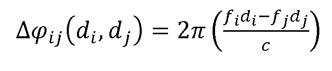
to the position of the electronic device 1200 compared with the two transmitters 1 10, 120. For the sake of brevity in the notation, the dependence on
 will be suppressed in the rest of the description.
• is the phase-offset between the two sources at the

reference time
 The phase offset can be derived from

equation (1 ) during a calibration procedure when, for example, distances
 , and time are known,

For the sake of clarity, the dependence on t0 will be suppressed in the notation. In the remainder of the description, it will be assumed (without loss of generality) that t0 = 0.
Equation (1 ) then provides the basis for both position and time estimates. Specifically, the phase difference (or phase shift) due to

position is related to the distances by the relationship:


Equivalently, this can be expressed in terms of the wavelengths of the signals from the two sources, using

 This phase-difference (or phase shift), in Equations (2) and (3), between the signals received from the two sources then provides the basis for a position estimate. Equations (2) and (3) can be considered as a kind of "differential pseudorange", compared with the pseudoranges used in conventional positioning systems.
As discussed in greater detail later below, the phase-shift in

Equations (2) and (3), (that is, the phase-difference due to position) can be derived either directly from the observed phase difference of Equation (1 ) for the combination of the two received signals or it can be derived by subtracting the separate phase measurements on each received signal. In

order to derive the value of the continuing phase rotation can be either

predicted at each time instant and then removed from equation (1 ) or simply filtered out by appropriate low-pass filters.
Once the phase-shift has been estimated then the difference term

in Equation (1 ) representing the continuing phase rotation can be used


to provide the basis for a detailed time estimate.
The sources may be:
• satellites (such as within and between GNSS systems, and within or between bands);
· terrestrial transmitters (such as cellular base stations, broadcast transmitters, which are commonly placed at different frequencies to avoid mutual interference - within or between bands, and within or between systems); or
• a mix of the two: some satellite and some terrestrial transmitters.
Calibration
Knowledge is needed, in some form, of the phase-offset between

the sources, as well of as the difference in frequency between them. Each source on its own will not usually be aware of or responsible for the phase and time offset compared with another source. Therefore, this is preferably obtained by some additional device, third party, or the receiver itself.
The phase reference may be obtained by measurement of the phase- offset either:
• concurrently at a known location by a reference device;
• previously at a known location and time by a reference device;
· previously at a known location and time by the receiver itself
In tracking applications, the receiver can readily calibrate the phase- offset from previous observations.
The usefulness of the measurement and of the calibration will depend on the relative drift between the two sources. Some transmitter systems are designed such that the relative drift between transmitters is closely controlled, even though the absolute frequency may drift significantly. If the position information is desired occasionally, after long intervals, then well -control led sources or a recent calibration should preferably be used.
Note that, according to some embodiments, it is not necessary to know the phase of each source,
 j if this is available it may be a means of establishing the phase-offset Δ It is the phase-offset that is

 desired to be calibrated.
Ambiguities
Measurement of phase means that there is an ambiguity of a multiple of 2π in the measurement. This will have an effect on the calculation of the phase difference (or phase shift due to position, as shown below:

or

Note that the integer can be either positive or negative considering that it

corresponds to the difference relationship between the two signals - not necessarily corresponding to the measurement of each of the signal at each of the carrier frequencies. This can be important, because the frequency difference will typically be a (small) fraction of the signal frequency, and hence
the ambiguity interval for the "difference signal" will be much larger than each of the signal frequencies. It should therefore be easier to resolve by other means. The ambiguity and its effect depend on the geometry. This will be discussed in greater detail later, below.
In some implementations, the phase-difference may be measured by first measuring each signal phase, and then performing a subtraction to find the difference. When each signal is measured there will be ambiguities in each signal phase measurement:

From these we can similarly form a difference phase metric

This is analogous to the integer ambiguity N discussed above for

direct differencing, with However, the integers in this case arise

in each of the individual carrier phase measurements, rather than as a result of the difference measurement. The phase-difference for multiple different signal sources
This section will discuss the behaviour and properties of the phase- difference
 (or phase shift) due to position derived between two signals received on different frequencies, coming from different sources. It should be remembered that the value of the derived phase-difference Δφ^ (or phase shift) as well as all plots shown in the following depend on the value of the phase-offset between the two sources referred to the reference time t0.
We can understand further how the phase-difference behaves by expressing the frequencies and distance differences for the two sources;

Next, we expand the equations in the form of these differences:

This leads to the equation:

where a wavelength corresponding to the frequency difference.

For convenience and without loss of generality, we can assume

We now consider some illustrative cases to explore the behaviour before turning to the general geometrical case.
Firstly, we note that the phase-difference increases as the distance from both the sources increases. Ultimately, when the difference between the distances to the two sources is small (for example when the receiver is far from the two sources), the metric reduces to:

This can be simplified as:

This situation approximates to a single source transmitting on two frequencies. In this case, there is an ambiguity corresponding to the wavelength of the frequency difference, Curves of constant

phase-difference are then simply circles (in two dimensions, or spheres in three dimensions), as illustrated in Fig. 2. For a given measured phase- difference, these curves represent a locus of positions at which the receiver could be located. The phase-difference simply increases according to the distance from the two signal sources. In this example, the sources are physically separated by 0.1 % of a wavelength. The different curves are for successive 2π ambiguities , so the plot gives a feel for the resolution and

accuracy, as well as the ambiguity of the measurement.
Secondly, the phase-difference also increases as the difference between the distances to the sources increases. Considering a different example case, in which the fractional difference between the frequencies is small compared with the fractional difference between the distances to the sources, the metric reduces to

This can be simplifie

This corresponds to a difference in the path corresponding to a single frequency. In this case, there is an ambiguity corresponding to the wavelength of the (approximately common) frequency of the sources, With the

two signals on approximately the same frequency, the curves of constant phase-difference are hyperbolae, in two dimensions, as shown in Fig. 3. Again, for a given measured phase-difference, these curves represent a locus of positions at which the receiver could be located. Again, the different curves are for successive 2n ambiguities with the detail of the central region shown in

the lower plot. The curves with the same value of plus and minus phase- difference are marked the same; and at ±10 phase the curves of constant phase-difference lie along the axis, outside the two sources. The difference between the frequencies in this example is small (i.e., 0.01 %).
In general, the phase depends on both the distance and the difference in distances between path lengths, with different effects depending on the frequency offset and the physical spacing between the sources.
Let's define the ratio of the frequencies:
This gives:
 This is a different criterion or metric from the difference measurement of the phase between two sources at the same frequency, and so provides distinct information compared to that case. The effect depends on the frequency difference and the geometry. Interestingly, compared with two signals from the same location, the separation of the sources results in a displacement and some deformation of the curves of constant phase- difference, as can be seen from the example of Fig. 4. This shows the phase- difference element of the circles, combined with the squeezing of the curves and the angular relationship in the central region between the sources, reminiscent of the hyperbolae. Note that some artefacts can be seen in Fig. 4, which are consequences of the sampling of the points on the curve.
Fig. 5 shows an example with a smaller frequency difference and a greater spacing between the sources in terms of the wavelengths of the difference frequency. The family of curves again gives successive 2π ambiguities showing the effect of the frequency offset and the geometry.

The small frequency difference in combination with a greater spacing between the sources resulted in a change in the shape of the curves compared with those in Fig. 3. Even though the frequency offset is small, its effect is still strong: one side of the sources forms a loop; and, on the other side, the variation of the phase-difference can now be observed even along the axis. Far away from the sources, the curves all tend towards circles - thus, even the curves initially diverging away from the sources still ultimately end up bending around to form a closed loop. Very far from the sources compared with the distance between them, the effect approximates to that for a single source transmitting on two frequencies. Note that some artefacts are also visible in Fig. 5 (notably around the shape of the -2 curve when it crosses the x axis).
We have seen already that the curves of constant phase-difference show some similarity to circles, dependent on the distance from both sources and some similarity to hyperbolae, dependent on the difference in distance to the sources. In fact, we can decompose the phase-difference directly into: (i) that due to the sum of the distances to the two sources; and (ii) that due to the difference between the distances to the two sources.
The phase-difference can usefully be expressed in terms of the sum and difference of the distances to the sources, as follows. Our starting point, putting on one side the calibration and ambiguity terms, is

We wish to express this in the form:

Comparing terms gives:

Therefore:

These are, respectively, the reciprocals of the wavelength of the average frequency and of the wavelength of the half frequency difference. We can now, as desired, express the phase-difference as:

The variation according to the difference in distance is the normal hyperbola, while the variation subject to the constraint that the sum of the distances to the two sources is a constant is an ellipse. An example of these two sets of curves plotted together is shown in Fig. 6.
The curves shown in Fig. 6 are significant. The hyperbolae show the effect of the difference between the distance to the two sources. The ellipses show the effect of a change in the sum of the distances to the two sources. The interval between the hyperbolae curves is determined by a combination of the wavelength of the average frequency, 2c/(/£ + /)·), and the separation between the sources. The interval between the ellipses is constant and equal
to the wavelength of the half frequency difference, . The form of the

hyperbolae and ellipses can clearly be seen to be locally orthogonal; in other words, if there is a change in the difference between the distances to the sources (while keeping the sum constant) then the device location moves onto a different hyperbola (while keeping on the same ellipse), while if there is a change in the sum of the distances to the sources (while keeping the difference between the distances constant) then the device location moves onto a different ellipse (while keeping on the same hyperbola). Note that, for clarity in plots of the hyperbolae, such as Fig. 6, parameter values are chosen close to those stated, in order to give curves that can be plotted (in particular, when the points are close to lying on the axis).
The observed variation of the phase-difference between the two signals is the combination of these two effects, as illustrated in Fig. 7. It can be seen how the asymmetrical curves of constant phase-difference are formed by the combination of the radial variation according to the set of ellipses combined with the transverse variation according to the set of hyperbolae. The curves of constant phase-difference pass through the set of intersections of each.
This decomposition makes clear how the family of curves of constant phase-difference and the tangential and radial spacing vary with the frequencies and geometry. The radial variation is determined by the separation of the frequencies. The transverse variation is determined by the number of wavelengths of the mid-frequency between the sources. At any particular location, the overall phase-difference is the sum of the radial and transverse components.
Satellite example
Within the L1 band, there is a small but significant frequency offset between the frequency of the GPS satellites and the centre of the band used by the GLONASS satellites. This offset is around 25MHz - a fractional ratio of 1 .017. Larger offsets are available if the L2 satellite signals are also used - for example, comparing a GLONASS L2 signal with GPS L1 signals - but the
advantage of exploiting only the L1 signals is that only one receiver band is needed.
It is informative to compare the results obtained when using phase- difference, according to an embodiment, with the information available from other measurements from the L1 signals from individual GPS and GLONASS satellites. Assuming satellites at ±5° overhead the user on the earth the following comparison of geometrical information can be derived:
• The individual code bits of the L1 signals have a data rate of 1 .023 Mb/s for GPS and 51 1 Kb/s for GLONASS. Measuring the phase the individual code bits translates to a vertical accuracy of 293 m and 587 m respectively.
• The individual carriers are at a frequency of 1 .575 GHz and 1 .602 GHz respectively. Measuring the carrier phase separately for each signal therefore translates to vertical ambiguity of 0.190 m and 0.187 m, respectively.
• The "difference frequency" (the difference between the carrier frequencies, which is the effective bandwidth of the phase-difference function) is about 27 MHz. Using phase-difference measurements, according to an embodiment, translates to ambiguity of 1 m horizontally and 1 1 m vertically.
Note that the GPS and GLONASS satellites are in orbits at different altitudes above the earth. This affects the geometry of the arrangement, particularly at times when they are relatively aligned to one another (from the perspective of the receiver), because the GPS satellite will be farther away from the receiver on the earth than the GLONASS satellite. Consequently the difference phase pattern will be inclined.
Terrestrial example
Cellular networks are widespread, and operate on a set of channels across a frequency band. Multiple cellular base stations are therefore transmitting signals on a set of different frequencies - both within a frequency band, and on different bands. This gives rise to a variety of opportunities for
measuring the phase-difference between signals coming from different transmitters, as a measurement to support positioning.
To calculate a position using terrestrial base stations only, an electronic device should make measurements from more than one base station. This is in contrast to the use of cellular base stations for communication, for which it is sufficient to be within the communication range of just one base station. Fortunately, in practice, signals from multiple base stations are observable in most places, for the following reasons:
• A network operator will deploy a set of base stations to give a wide coverage, and it will often be possible to receive the signals from neighbouring cells of the same network;
• Multiple network operators compete for business and so there are multiple cellular network deployments, with overlapping coverage;
• A single network operator may operate across multiple channels or bands, in order to provide sufficient communications capacity.
The different network operators are usually assigned different (sets of) frequencies, on which to use their base stations. In some systems, such as GSM, each base station in a locality transmits on a different frequency in order to avoid interference (Frequency Division Multiple Access, FDMA).
An example deployment of Long Term Evolution (LTE) base stations is shown in Fig. 8. At the time of the survey, two network operators had LTE cellular systems deployed in Rapperswil, with the two systems operating at frequencies of 1838.5 and 1852MHz, respectively. Sometimes base stations on different frequencies, from the two operators, are placed close together, for example those indexed as BS_9 and BS_10, while sometimes there are base stations separated more widely, for example those indexed BS_1 and BS_3 which are separated by about 750m. As users move around the town, their mobile electronic devices will be able to receive signals with carriers on both frequencies, and that the devices could therefore measure the difference of the phase of these various signals, in accordance with an embodiment. Note that, when measuring and using the phase-difference between transmitters, the timing stability (absolute and relative) of these base stations will affect
accuracy. In particular, the timing stability will determine how the measurement-accuracy degrades over time after calibration.
In the satellite example, discussed above, the receiving device was far from the transmitters but, for the terrestrial case, the receiver is usually placed among the transmitters. In the example shown in Fig.8, the separation of the signals is just 1852-1838.5=13.5MHz (a difference of <1 %) and the base stations visible at the receiver are usually separated by no more than 750m (or several thousand wavelengths). The behaviour of the phase-difference however follows the same principles that were described previously above. This is shown firstly in Fig. 9, for a slightly simpler example for ease of illustration, with a frequency ratio r (a difference of 5%, 90MHz) and a

separation between the sources of 100 carrier wavelengths (about 16m). The receiver could be located in a central region, between the two base stations, or outside them, to the left or right. The central region is shown in Fig. 9(a) with lines of constant phase every with a correspondingly wider spaced set

of hyperbolae to show the underlying framework. The regions either side are shown in Figs. 9(b) and 9(c) with single-cycle ambiguity of phase 2π , again with a corresponding set of hyperbolae in each case. There are some small irregularities in the smooth curves but these are due to numerical limitations in the curve plotting. This will be discussed in greater detail later, below. Turning now to a more representative example, Fig. 10 shows the family of constant- phase-difference curves for a smaller frequency offset of just


Recall the decomposed difference equation for phase-difference processing:


From this, it can be seen that the measurement precision is determined by the following factors:
• The precision with which the phase-difference Δφ^ is measured. This is based on the measurement of the time, or equivalently the phase of the difference signal, and depends on the signal to noise ratio and the frequency difference (that is, the bandwidth occupied). In a simple

noisy environment, the measurement performance is governed by the
Cramer Rao bound, and the measurement precision in time will improve as the bandwidth increases.

• Timing errors in the receiver, which affect the derivation of These

might be knowable and corrected, and small errors in the time domain will probably have negligible effect on the precision of the end result.
• Systematic timing errors in the sources, which affect Δ These might

also be knowable and corrected. Small errors in the time domain will probably again have negligible effect on the precision of the end result.
• The accuracy with which the transmitter phase-offset Δ is calibrated;

this will be discussed further below.
• The accuracy with which the ambiguity N is reliably resolved.

Depending on the use case, the ambiguity resolution has to be performed by other means, and other measurements. The accuracy with which this has to be done is the local effective wavelength, A£j-, which describes the 2π periodicity of phase-difference in space. The shorter the effective wavelength, the better the ambiguity resolution needs to be in order to obtain a unique accurate solution.
• The conversion of the measured phase-difference into a distance error, which is determined by the local effective wavelength that describes
 the conversion of the phase-difference into distance. The shorter the effective wavelength, the sharper the spatial resolution that is achieved, proportionately.
Based on the above considerations, the following conclusions can be drawn:
• The precision is at its best in configurations where the sources are well separated.
• The accuracy is limited by the accuracy to which the phase-offset between the sources is calibrated.
Usage
The measurement of the difference in phase can lead to the estimation of the differential pseudorange for position and/or time estimation; position and/or time can be estimated for the target device or for the sources, and position and/or time can be estimated in absolute terms or relative to previous position and/or time estimates. The phase-difference metric according to embodiments of the present invention is suitable for combination with other conventional metrics used for positioning, such as time of arrival and time difference of arrival, using multiple sources, and multiple signals from the sources to additionally constrain the position solution.
Because of its properties as a phase measurement at an effective "difference frequency", which leads to good accuracy with moderate

ambiguity, the phase-difference metric may be particularly suitable for improving the accuracy of an estimated position. The technique might be particularly useful when the carrier phase measurement of each signal on its own is not available. This may arise when:
• The carrier phase is not measured by the receiver.
• The noise or multipath conditions make the measurement and tracking of the carrier phase unreliable.
· The ambiguity in the carrier phase measurement is not available or not reliable.
In these cases, the use of the phase-difference might offer improved performance, compared with the use of code measurements for each signal separately. In practice, a combination of measurements might be desirable to resolve the ambiguities and benefit from the improved precision that comes from the measurement of the phase-difference.
Measurement of phase-difference in practice
The measurement of the phase-difference between two signals can be done either directly, by comparing the two signals, or indirectly, by measuring the phase of each signal compared to a reference (as in a conventional carrier measurement by a receiver) and then subtracting the result for the two signals. This is an implementation choice. An example for the direct approach is the complex cross-multiplication and combination of the two signals using the trigonometric identities and removing the component at by filtering,

which leaves:
and
 from which the difference measurements can be made.
Measurement of phase for individual satellite signals will be familiar to those skilled in the art. Further details about the measurement of phase for terrestrial cellular signals may be found in: Carlemalm and Poor (C. Carlemalm and H.V. Poor "Joint Carrier Phase and Frequency Offset Tracking in OFDM Systems", Proceedings of the 10th European Signal Processing Conference, Tampere, Finland, 4-8 September 2000); and Huq et al. (AT. Huq, E.Panayirci, and C.N. Georghiades, "ML NDA Carrier Phase Recovery for OFDM Systems", Proceedings of the IEEE International Conference on Communications (ICC), vol. 2, p.786-790, 6-10 June 1999).
In practice, each signal source is not a continuous wave signal, but has modulation on a carrier. In some cases, it may be beneficial to remove this
modulation by signal processing as part of (or before) the measurement of the phase-difference between the two carrier signals.
A typical receiver only has one antenna and front end, and will receive multiple signals of different signal amplitudes, and frequencies (and phases) in combination together; these should then be separated into the available signals for finding position.
With more than two signals present, the set of pairs of signals will each give difference information that is available to be measured by the signal processing and combined by the positioning algorithms.
Potential Benefits
The approach of using sources (transmitters) with different signal- frequencies may be useful for a variety of reasons:
• More terrestrial base stations are becoming better controlled. Their frequency is usually stable, and possibly locked to UTC via GPS. This has an indirect positive effect on the stability of the frequency-offset between transmitters.
• More sources (transmitters) are becoming available:
o Firstly, through widespread deployment of high quality cellular base stations and femto-cells, to increase communication network capacity,
o Secondly, through multiple satellite navigation systems and satellites. Embodiments of the present invention can exploit not only each signal individually, but also the differences between them.
As mentioned previously above, it is expected that the present phase- difference approach will be useful for satellite positioning. The GPS signals and the GLONASS signals in the L1 band are transmitted on 1 .575GHz and in a band around 1 .602GHz respectively, so they are separated by around 27MHz. The bandwidth of the combined signal is a factor of ten greater than the bandwidth of a GPS signal, offering the potential for much higher accuracy and resolution than the use of the code signals of either GPS or GLONASS on
its own. This is true even though the receiver is still operating solely within the L1 band, and is not calling upon the additional capability (and additional satellites) of the wideband signal E5a+E5b, which will be offering a similar bandwidth signal when it is transmitted in due course by Galileo satellites.
As remarked, since the bandwidth of the combined signal is a higher frequency than the code modulation of GPS (or of GLONASS), it gives additional measurement and positioning possibilities for the receiver. Because it relies on a difference measurement it also carries information about the distance from the satellites. This may offer improved precision, vertically as well as horizontally.
Compared with (or complementing) measurement of each carrier phase, the approach might bring advantages in:
• The calibration and ambiguity resolution of just one parameter - namely, the phase- difference between the GPS and GLONASS signals - without requiring the ambiguity resolution of the phase of each satellite separately (two parameters).
• The ease and robustness of the measurement of the phase-difference between the signals (at an effective bandwidth of ~27MHz), compared with the precise measurement of the phase of each carrier individually (at -1 .5GHz).
• Together with the normal code measurements, convenient precision in the estimation of the distance from the satellites to help resolve ambiguity in the carrier measurements.
The present examples consider the FDMA GLONASS signals that are currently available. The new generation of GLONASS-K2 satellites scheduled for launch over the period 2015 - 2024 will continue to support these FDMA signals, but will also transmit a CDMA signal at 1 .601 GHz. The phase- differencing approach could also be applied to these new satellites and signals.
It is also expected that the present phase-difference approach will be useful for positioning based on radio signals from terrestrial base stations.
Cellular systems are constructed with multiple base stations, some of which are on the same frequency (for example, in the case of Code Division Multiple Access, CDMA, systems) and some of which are on different frequencies (to avoid interference). Typically different network operators purchase and use different bandwidth in the spectrum and have their own set of base station frequencies. By exploiting the signals from base stations which are on different frequencies, embodiments can assist positioning using signals in FDMA systems and can combine signals from multiple base stations and multiple network operators. This can increase the availability of measurements compared with those that can be used by any single network operator, which in turn can improve the likelihood of an electronic device being able to calculate a position estimate, and/or potentially improves the precision of such an estimate. The use of phase-difference can be considered as exploiting a notional combined signal, whose bandwidth is equal to the frequency difference between the two underlying signals. This can be a large bandwidth, because it is that of the separation between cellular base stations across a band, and even between bands - not just the bandwidth of the individual channel or single base station transmitter. Again, the increased bandwidth of the phase-difference measurement compared with that of each signal on its own can offer increased resolution, increased accuracy, and improved ability to combat multipath.
Embodiments can also allow measurements to be combined among signals transmitted by satellites and signals transmitted by terrestrial base stations. This can provide many more sources that can be used to support positioning. As mentioned already above, it may be particularly helpful for vertical positioning, as the vertical range of angle (and Dilution of Precision) will be much greater when combining satellites and terrestrial sources, than achievable with any one system on its own. The satellite signals and terrestrial signals are comfortably spaced in separate bands to avoid interference, providing a useful bandwidth for the phase-difference measurement. The potential high precision of using the phase-difference may be particularly
desirable for finding the altitude of an electronic device and - in the case of indoor positioning - which floor of a building the user is on.
Embodiments
Fig. 1 1 is a flowchart illustrating a method for assisting a determination of the position of a receiver, according to an embodiment of the first aspect. According to this embodiment, the method is performed by an electronic device 1200. Fig. 12 is a block diagram of this device. The electronic device 1200 comprises a receiver 1210 that is adapted to receive signals from LTE base stations. It is coupled to an associated antenna 1215. The electronic device 1200 also comprises a GNSS receiver 1230, adapted to receive satellite positioning signals via the associated antenna 1235. Both of the receivers 1210 and 1230 are coupled to a processor 1220, which is adapted to process and analyse the received signals. A clock 1225 is provided, coupled to the processor 1220, for providing a local timing reference for measurements of time and phase of the received signals. The processor 1220 is also coupled to a memory 1240, which can be used to store calibration information for use in the position calculation. The electronic device 1200 further comprises an output device 1250, such as a display screen, for outputting the calculated position information. The electronic device 1200 may be a portable electronic device such as a portable navigation device or a mobile communications device (for example, a smart phone).
For the purposes of the following description, the LTE receiver 1210 and the GNSS receiver 1230 will be considered as a single, combined "receiver" that is capable of receiving both cellular communication signals and satellite positioning signals. Thus, references to "receiving" signals at the "receiver" can refer to either type of signal received by either receiver and references to the "position of the receiver" refer to the position of the electronic device 1200 since both the LTE receiver 1210 and the GNSS receiver 1230 are located within this device. In other words, the small difference in position between the LTE antenna 1215 and the GNSS antenna 1235 can be neglected for the present purposes.
At step 1 1 10, the receiver 1210, 1230 receives a first radio signal transmitted by a first transmitter 1 10 (see Fig. 1 ). At step 1 120, the receiver 1210, 1230 receives a second radio signal transmitted by a second transmitter 120. The first transmitter 1 10 and the second transmitter 120 are at different locations and the first signal is transmitted at a first frequency that is different from a second frequency of the second signal. The first and second signals may be two satellite positioning signals from different satellites transmitting at different frequencies (both received by the GNSS receiver 1230). Alternatively, the first and second signals may be two LTE signals received from different base stations operating on different channels (both received by the LTE receiver 1210). In still another alternative, one signal is received via the LTE receiver 1210 and the other signal is received via the GNSS receiver 1230.
In step 1 130, the processor 1220 compares a first phase of the first signal with a second phase of the second signal to produce a phase- comparison. In the present embodiment, this comprises measuring or calculating the phase-difference between the two received signals. In step 1 140, the processor 1220 obtains calibration information to be used in the position calculation. The calibration information comprises a phase-offset between the signal transmitted by the first transmitter 1 10 and the signal transmitted by the second transmitter 120, at a specific reference time. The calibration information therefore defines a phase relationship between the two transmitters' signals at the reference time. To the extent that the two transmitters are stable with respect to one another (that is, to the extent that their timing and frequency do not drift relative to one another) the phase relationship will evolve in a predictable way. Therefore, knowing the phase relationship at the reference time effectively allows it to be predicted at a future (or past) time. The calibration information may be stored in the memory 1240 of the electronic device 1200 or it may be retrieved from a remote server 1500, where it is stored in a database 1510. The electronic device 1200 can communicate with the server 1500 over a suitable communications network, including but not limited to a mobile communications network such as an LTE network or the internet.
In step 1 150, the processor 1220 constructs a first equation that relates the measured phase-difference to the distances between the receiver and the respective transmitters. This equation defines a locus of positions at which the receiver 1210, 1230 could be located, based on the phase-difference that has been measured. The first equation may include a term relating to the calibration information (phase-offset) and a term relating to time.
In step 1 160, the processor 1220 solves the first equation to calculate the position of the receiver 1210, 1230. Typically, the first equation cannot be solved in isolation - some additional information is needed to produce a unique solution. This additional information may be obtained by measuring phase-differences for other pairs of transmitters whose signals are received by the receiver 1210, 1230. In other words, steps 1 1 10 to 1 150 may be repeated for other pairs of transmitters. This leads to a set of simultaneous equations which may be solved together to calculate a unique position solution. Alternatively or in addition, the phase-difference information may be supplemented by or combined with other sources of positioning information, including but not limited to: satellite pseudoranges; beacon-based position information (in which position information can be deduced by detecting signals from one or more radio beacons such as wireless network base stations); and ranging information or direction of arrival information from so-called "signals of opportunity", such as digital video or digital audio broadcasts or mobile communication signals. Other suitable sources of positioning information and means of combining positioning information will be known to those skilled in the art.
The first equation (and optionally any further equations based on phase- differences between other pairs of transmitters) is/are preferably based on one of the difference equations discussed in detail already, above. Note that it is not essential that the first signal and the second signal are received concurrently. However, since the method relies on comparing the phases of the two signals, their relative timing should be recorded implicitly or explicitly - particularly if the signals were not received concurrently.
Fig. 13 is a flowchart of a method according to an embodiment of the second aspect. This is a method of producing calibration information (such as phase-offsets) for use in the method of Fig. 1 1 . In step 1 1 10a, the receiver 1210, 1230 receives a first radio signal transmitted by a first transmitter 1 10. In step 1 120a, the receiver 1210, 1230 receives a second signal from a second transmitter 120. These steps are substantially similar to steps 1 1 10 and 1 120 in the method of Fig. 1 1 , with the principle difference being that, in the method of Fig. 13, the position of the receiver 1210, 1230 (that is, the position of the electronic device 1200) is known. Furthermore, the time at the receiver is known relative to the times at the two transmitters. Thus, the signals are received at a known calibration location at a known calibration time.
In step 1 130a, the processor 1220 compares a first phase of the first signal with a second phase of the second signal to determine a phase-offset between the signals. Again, this step is similar to step 1 130 of Fig. 1 1 . In step 1 130, the phase-difference was measured in order to determine the position of the electronic device 1200; in step 1 130a the phase-difference is measured to determine the phase-offset between the two transmitters. In step 1340, the processor provides the calibration information for subsequent use in a method according to Fig. 1 1 . The calibration information may be stored by the processor 1220 in the memory 1240 or it may be submitted to a server 1500 for storage in a database 1510 of calibration information. If it is stored in the memory 1240 it may be available for use by the same electronic device 1200 by which is was created. If it is stored in the remote database 1510, it may be available for use by other electronic devices. Preferably, the calibration information comprises both the phase-offset and the reference time to which this phase-offset refers. The reference time may be the time at which the phase-offset was observed - that is, the known calibration time - although this is not essential. Alternatively, in some embodiments, all phase-offsets may be referred to a universally fixed reference time - for example, GPS time zero. In this case, it may not be necessary to record the reference time explicity, because it is understood implicitly.
Fig. 14 is a flowchart illustrating a method of maintaining and providing calibration information according to an embodiment of the third aspect. Fig. 15 is a block diagram of a server 1500 adapted to perform the method of Fig. 14. The server 1500 comprises a database 1510; a processor 1520; and a network interface 1530, coupled to one another via a bus. The network interface is coupled to a communications network (not shown) for obtaining calibration information from electronic devices and providing calibration information to those devices (or other devices), upon request. The calibration information is stored in the database 1510. The processor 1520 is configured to process the calibration information and search the database 1510 for calibration information, in response to receipt of a request.
In step 1410, the processor maintains the database 1510 of calibration information. The calibration information comprises phase-offsets between pairs of transmitters, as described already above. This calibration information can be produced by a plurality of receivers in electronic devices operating according to the method of Fig. 13. The step 1410 of maintaining the database 1510 comprises obtaining calibration information (that is, phase-offsets, optionally together with their associated reference times) from the electronic devices, along with information identifying the respective pairs of transmitters to which the phase-offsets relate. In step 1420, the processor 1520 receives a request for calibration information from one of the electronic devices 1200 via the network interface 1530. The request identifies a pair of transmitters whose phase-offset is required in order to calculate the position of the electronic device 1200. In response to the request, at step 1430, the processor 1520 searches the database 1510 to retrieve the requested phase-offset information. Once retrieved, the phase-offset information is provided to the requesting electronic device 1200 in step 1440 (preferably together with the reference time that is associated with the phase-offset, if this is recorded in the database).
The database 1510 may store calibration information for pairs of transmitters of a variety of diverse types. These may include mobile communications base stations controlled by various different network
operators as well as satellites of multiple different GNSS constellations. In general, the greater the diversity of transmitters and transmitter types, the more useful the calibration information may be for positioning. Therefore, the database 1510 is preferably not limited to describing transmitters of a single network operator or a single satellite positioning system.
In the method of Fig. 1 1 , described above, it is assumed that the locations of the first and second transmitters 1 10, 120 are known. This is not essential in all circumstances; however, it is desirable in many situations. Fig. 16 illustrates a method of assisting in the calculation of transmitter locations according to an embodiment of the fourth aspect. The calculated transmitter locations can then be used in embodiments of the method of Fig. 1 1 .
In step 1 1 10b, the receiver 1210, 1230 receives a first radio signal transmitted by the first transmitter 1 10. In step 1 120b, the receiver 1210, 1230 receives a second signal transmitted by the second transmitter 120. The steps 1 1 10b and 1 120b are similar to the steps 1 1 10 and 1 120, respectively, in the method of Fig. 1 1 . In step 1 130b, the processor 1220 compares a phase of the first signal with a phase of the second signal by measuring or calculating the phase-difference between them. This step is similar to step 1 130 in the method of Fig. 1 1 . In step 1640, the processor 1220 uses the measured phase- difference from step 1 130b to calculate the location of the first transmitter 1 10. This is similar to the method used to calculate the position of the receiver in the embodiment of Fig. 1 1 . A similar set of equations is constructed (as discussed previously in greater detail above) and the set of equations is then solved. The principle difference is that instead of (or in addition to) the position of the receiver 1210, 1230 being unknown, the location of the first transmitter 1 10 is (also) unknown. When calculating the location of a transmitter in this way, it may be preferable for the location of the receiver 1210, 1230 (of the electronic device 1200) to be known. However, this is not essential, provided that sufficient sources of information are available. In general, the set of simultaneous equations will be possible to solve if there are more equations than unknown variables in the equations. Although the foregoing example
refers to calculating the location of the first transmitter, those skilled in the art will appreciate that the location of the second transmitter may be calculated (alternatively or in addition) in a similar way.
In the embodiments described above, the ultimate goal of each method was to calculate the position of a receiver 1210, 1230 in an electronic device 1200 or to calculate the location of a transmitter 1 10, 120. However, it is also possible to calculate time in a similar way. For example, the method of Fig. 1 1 can be adapted so that the time is one of the unknown variables in the system of simultaneous equations constructed in step 1 150. This may be instead of or in addition to the position of the receiver 1210, 1230 being unknown. Likewise, the method of Fig. 16 can be adapted to calculate the time at the transmitter. In the same way that methods of calculating position are useful, to determine the precise position of an electronic device 1200 or transmitter 1 10, 120, methods of calculating time are also useful for precise time-synchronisation - both to support accurate positioning and to support other applications.
The embodiments described above have referred to LTE networks and LTE signals. However, other embodiments may use signals from other types of mobile communication networks, or signals from terrestrial transmitters other than cellular base stations. In general, any kind of signal from any transmitter can be exploited, provided that its timing and phase is relatively stable and provided that some information is available about the source and content of the signal.
It should be noted that the above-mentioned embodiments illustrate rather than limit the invention, and that those skilled in the art will be able to design many alternative embodiments without departing from the scope of the appended claims. In the claims, any reference signs placed between parentheses shall not be construed as limiting the claim. The word "comprising" does not exclude the presence of elements or steps other than those listed in a claim. The word "a" or "an" preceding an element does not exclude the presence of a plurality of such elements. The embodiments may be implemented by means of hardware comprising several distinct elements. In a device claim enumerating several means, several of these means may be
embodied by one and the same item of hardware. The mere fact that certain measures are recited in mutually different dependent claims does not indicate that a combination of these measures cannot be used to advantage. Furthermore in the appended claims lists comprising "at least one of: A; B; and C" should be interpreted as (A and/or B) and/or C.
Furthermore in general, the various embodiments may be implemented in hardware or special purpose circuits, software, logic or any combination thereof. For example, some aspects may be implemented in hardware, while other aspects may be implemented in firmware or software which may be executed by a controller, microprocessor or other computing device, although these are not limiting examples. While various aspects described herein may be illustrated and described as block diagrams, flow charts, or using some other pictorial representation, it is well understood that these blocks, apparatus, systems, techniques or methods described herein may be implemented in, as non-limiting examples, hardware, software, firmware, special purpose circuits or logic, general purpose hardware or controller or other computing devices, or some combination thereof.
The embodiments described herein may be implemented by computer software executable by a data processor of the apparatus, such as in the processor entity, or by hardware, or by a combination of software and hardware. Further in this regard it should be noted that any blocks of the logic flow as in the Figures may represent program steps, or interconnected logic circuits, blocks and functions, or a combination of program steps and logic circuits, blocks and functions. The software may be stored on such physical media as memory chips, or memory blocks implemented within the processor, magnetic media such as hard disk or floppy disks, and optical media such as for example DVD and the data variants thereof, CD.
The memory may be of any type suitable to the local technical environment and may be implemented using any suitable data storage technology, such as semiconductor-based memory devices, magnetic memory devices and systems, optical memory devices and systems, fixed memory and removable memory. The data processors may be of any type suitable to the
local technical environment, and may include one or more of general purpose computers, special purpose computers, microprocessors, digital signal processors (DSPs), application specific integrated circuits (ASIC), gate level circuits and processors based on multi-core processor architecture, as non- limiting examples.
Embodiments as discussed herein may be practiced in various components such as integrated circuit modules. The design of integrated circuits is by and large a highly automated process. Complex and powerful software tools are available for converting a logic level design into a semiconductor circuit design ready to be etched and formed on a semiconductor substrate.
Claims
1 . A method for assisting a determination of a position of a receiver (1210, 1230) and/or a time at the receiver, the method comprising:
receiving (1 1 10) at the receiver (1210, 1230) a first radio signal transmitted at a first frequency by a first transmitter (1 10);
receiving (1 120) at the receiver (1210, 1230) a second radio signal transmitted at a second frequency by a second transmitter (120), wherein the second transmitter (120) is at a different location from the first transmitter (1 10) and the second frequency is different from the first frequency;
comparing (1 130) a first phase of the received first radio signal with a second phase of the received second radio signal to produce a phase- comparison; and
using (1 150, 1 160) the phase-comparison to assist in the calculation of the position of the receiver and/or the time at the receiver.
2. The method of claim 1 , wherein the phase-comparison comprises a phase-difference between the first phase and the second phase.
3. The method of claim 2, wherein the phase-difference includes an ambiguity and the step (1 150, 1 160) of using the phase-comparison to assist in the calculation of the position of the receiver and/or the time at the receiver comprises resolving the ambiguity.
4. The method of any one of claims 1 to 3, wherein the step of using the phase-comparison comprises constructing (1 150) a first equation that relates the phase-comparison to:
a first distance between the receiver and the first transmitter; and a second distance between the receiver and the second transmitter.
5. The method of claim 4, wherein the first equation defines a locus of positions at which the receiver (1210, 1230) could be located.
6. The method of claim 5, wherein the method further comprises:
constructing one or more further equations each of which defines a further locus of positions at which the receiver could be located; and
solving the first equation and the one or more further equations together, to calculate the position of the receiver.
7. The method of any one of claims 4 to 6, wherein the first equation further relates the phase-comparison to the time.
8. The method of any one of the preceding claims, further comprising obtaining (1 140) calibration information, comprising a phase-offset between the first signal and the second signal at a reference time,
and wherein the step (1 150, 1 160) of using the phase-comparison to assist in the calculation of the position of the receiver and/or the time at the receiver employs the calibration information.
9. The method of claim 8, wherein the calibration information is obtained from a database (1510) of known phase-offsets between pairs of transmitters.
10. A method of producing calibration information, the method comprising: receiving (1 1 10a) at a receiver (1210, 1230) a first radio signal transmitted at a first frequency by a first transmitter (1 10);
receiving (1 120a) at the receiver (1210, 1230) a second radio signal transmitted at a second frequency by a second transmitter (120), wherein the second transmitter is at a different location from the first transmitter and the second frequency is different from the first frequency,
wherein the signals are received at a known calibration location at a known calibration time,
the method further comprising comparing (1 130a) a first phase of the received first radio signal with a second phase of the received second radio signal to determine a phase-offset between the signals,
wherein the calibration information comprises the determined phase- offset.
1 1 . A method of providing calibration information for assisting a determination of a position of a receiver (1210, 1230) and/or a time at the receiver, the method comprising:
maintaining (1410) a database (1510) of calibration information, the calibration information comprising phase-offsets between pairs of radio signals transmitted by respective pairs of transmitters;
receiving (1420) a request for calibration information, wherein the request identifies a pair of transmitters (1 10, 120) whose phase-offset is required;
searching (1430) the database (1510) to find the phase-offset between the identified pair of transmitters; and
providing (1440) the found phase-offset in response to the request.
12. The method of claim 1 1 , wherein the calibration information is produced by a plurality of receivers, and the step of maintaining the database comprises obtaining (1410) the calibration information from the receivers.
13. A method for assisting a calculation of a location of a transmitter (1 10, 120) and/or a time at a transmitter (1 10, 120), the method comprising:
receiving (1 1 10b) at a receiver (1210, 1230) a first radio signal transmitted at a first frequency by a first transmitter (1 10);
receiving (1 120b) at the receiver (1210, 1230) a second radio signal transmitted at a second frequency by a second transmitter (120), wherein the second transmitter is at a different location from the first transmitter and the second frequency is different from the first frequency;
comparing (1 130b) a first phase of the received first radio signal with a second phase of the received second radio signal to produce a phase- comparison; and
using (1640) the phase-comparison to assist in the calculation of at least one of: the location of the first transmitter (1 10); the location of the second transmitter (120); a time at the first transmitter (1 10) when the first radio signal was transmitted; and a time at the second transmitter (120) when the second radio signal was transmitted.
14. The method of any one of the preceding claims, wherein one of the following conditions is met:
each of the first transmitter (1 10) and the second transmitter (120) is a terrestrial transmitter;
each of the first transmitter (1 10) and the second transmitter (120) is an orbiting satellite transmitter; or
the first transmitter (1 10) is a terrestrial transmitter and the second transmitter (120) is an orbiting satellite transmitter.
15. The method of any one of the preceding claims, wherein the first transmitter (1 10) is part of a first wireless network and the second transmitter (120) is part of a second, different wireless network.
16. The method of any one of the preceding claims, wherein the first radio signal and the second radio signal are transmitted by the first transmitter (1 10) and the second transmitter (120), respectively, at different times.
17. A computer program comprising computer program code adapted to control an electronic device (1200) to perform all the steps of any one of the preceding claims if said program is run on a processor (1220) of said electronic device (1200).
18. An electronic device (1200) operable to determine its position and/or time, the electronic device (1200) comprising:
a receiver (1215, 1235), adapted to:
receive a first radio signal transmitted at a first frequency by a first transmitter; and
receive a second radio signal transmitted at a second frequency by a second transmitter, wherein the second transmitter is at a different location from the first transmitter and the second frequency is different from the first frequency; and
at least one processor (1220), adapted to:
compare a first phase of the received first radio signal with a second phase of the received second radio signal to produce a phase- comparison; and
use the phase-comparison to assist in the calculation of the position of the electronic device and/or the time at the electronic device.
19. The electronic device of claim 18, wherein the processor (1220) is further adapted to:
obtain calibration information, comprising a phase-offset between the first signal and the second signal at a reference time; and
employ the calibration information when using the phase-comparison to assist in the calculation of the position of the electronic device and/or the time at the electronic device,
wherein the processor (1220) is adapted to obtain the calibration information from a database and the database is stored:
at least in part in a memory (1240) of the electronic device; and/or at least in part remotely from the electronic device.
20. An electronic device (1200) operable to produce calibration information for determining position and/or time, the electronic device comprising:
a receiver (1210, 1230), adapted to, at a known calibration location and a known calibration time:
receive a first radio signal transmitted at a first frequency by a first transmitter;
receive a second radio signal transmitted at a second frequency by a second transmitter, wherein the second transmitter is at a different location from the first transmitter and the second frequency is different from the first frequency, and
a processor (1220), adapted to compare a first phase of the received first radio signal with a second phase of the received second radio signal in order to determine a phase-offset between the signals,
wherein the calibration information comprises the determined phase- offset.
21 . An electronic device (1200) operable to assist in the determination of a location of a transmitter and/or a time at a transmitter, the electronic device comprising:
a receiver (1210, 1230), adapted to:
receive a first radio signal transmitted at a first frequency by a first transmitter;
receive a second radio signal transmitted at a second frequency by a second transmitter, wherein the second transmitter is at a different location from the first transmitter and the second frequency is different from the first frequency, and
a processor (1220), adapted to:
compare a first phase of the received first radio signal with a second phase of the received second radio signal to produce a phase- comparison; and
use the phase-comparison to assist in the calculation of at least one of: the location of the first transmitter; the location of the second transmitter; a time at the first transmitter when the first radio signal was transmitted; and a time at the second transmitter when the second radio signal was transmitted.
Priority Applications (4)
| Application Number | Priority Date | Filing Date | Title |
|---|---|---|---|
| PCT/EP2016/058032 WO2017178041A1 (en) | 2016-04-12 | 2016-04-12 | Phase-comparison for assisting the determination of position or time |
| US16/093,105 US11175413B2 (en) | 2016-04-12 | 2017-04-12 | Phase-comparison for assisting the determination of position or time |
| PCT/EP2017/058892 WO2017178573A2 (en) | 2016-04-12 | 2017-04-12 | Phase-comparison for assisting the determination of position or time |
| EP17717416.6A EP3443386A2 (en) | 2016-04-12 | 2017-04-12 | Phase-comparison for assisting the determination of position or time |
Applications Claiming Priority (1)
| Application Number | Priority Date | Filing Date | Title |
|---|---|---|---|
| PCT/EP2016/058032 WO2017178041A1 (en) | 2016-04-12 | 2016-04-12 | Phase-comparison for assisting the determination of position or time |
Publications (1)
| Publication Number | Publication Date |
|---|---|
| WO2017178041A1 true WO2017178041A1 (en) | 2017-10-19 |
Family
ID=55808560
Family Applications (2)
| Application Number | Title | Priority Date | Filing Date |
|---|---|---|---|
| PCT/EP2016/058032 Ceased WO2017178041A1 (en) | 2016-04-12 | 2016-04-12 | Phase-comparison for assisting the determination of position or time |
| PCT/EP2017/058892 Ceased WO2017178573A2 (en) | 2016-04-12 | 2017-04-12 | Phase-comparison for assisting the determination of position or time |
Family Applications After (1)
| Application Number | Title | Priority Date | Filing Date |
|---|---|---|---|
| PCT/EP2017/058892 Ceased WO2017178573A2 (en) | 2016-04-12 | 2017-04-12 | Phase-comparison for assisting the determination of position or time |
Country Status (3)
| Country | Link |
|---|---|
| US (1) | US11175413B2 (en) |
| EP (1) | EP3443386A2 (en) |
| WO (2) | WO2017178041A1 (en) |
Cited By (1)
| Publication number | Priority date | Publication date | Assignee | Title |
|---|---|---|---|---|
| WO2018100189A1 (en) | 2016-12-01 | 2018-06-07 | U-Blox Ag | Intercepting an uplink signal to assist in timing or positioning calculations |
Families Citing this family (10)
| Publication number | Priority date | Publication date | Assignee | Title |
|---|---|---|---|---|
| US11057862B2 (en) | 2018-08-26 | 2021-07-06 | Celeno Communications (Israel) Ltd. | Wi-Fi radar detection using synchronized wireless access point |
| EP3906426B1 (en) | 2018-12-31 | 2025-04-02 | Celeno Communications (Israel) Ltd. | Coherent wi-fi radar using wireless access point |
| US11102750B2 (en) * | 2019-01-01 | 2021-08-24 | Celeno Communications (Israel) Ltd. | Positioning system based on distributed transmission and reception of Wi-Fi signals |
| WO2021033085A1 (en) * | 2019-08-16 | 2021-02-25 | Telefonaktiebolaget Lm Ericsson (Publ) | Frequency adjustment for non-terrestrial networks |
| JP7547859B2 (en) * | 2020-08-24 | 2024-09-10 | 日本電気株式会社 | Topology calculation device, terminal, communication system, topology calculation method, and topology calculation program |
| US11683772B2 (en) * | 2021-03-12 | 2023-06-20 | Cisco Technology, Inc. | Continuous synchronization of multiple radio devices to physical time |
| JP7347840B2 (en) * | 2021-05-26 | 2023-09-20 | Rika株式会社 | Real-time dynamic satellite positioning system and positioning method |
| FI20216241A1 (en) | 2021-12-02 | 2023-06-03 | Nokia Technologies Oy | Device positioning |
| EP4194899A1 (en) * | 2021-12-07 | 2023-06-14 | u-blox AG | Demodulating qzss signals |
| WO2023186135A1 (en) * | 2022-03-31 | 2023-10-05 | 华为技术有限公司 | Method for determining positioning information, and positioning method and related apparatuses |
Citations (3)
| Publication number | Priority date | Publication date | Assignee | Title |
|---|---|---|---|---|
| US3967277A (en) * | 1968-03-14 | 1976-06-29 | Teledyne, Inc. | Radio navigation system |
| DE4223194C1 (en) * | 1992-07-15 | 1993-08-26 | Grundig E.M.V. Elektro-Mechanische Versuchsanstalt Max Grundig Hollaend. Stiftung & Co Kg, 8510 Fuerth, De | |
| US20150006073A1 (en) * | 2008-03-31 | 2015-01-01 | Golba Llc | Methods and systems for determining the location of an electronic device using multi-tone frequency signals |
Family Cites Families (11)
| Publication number | Priority date | Publication date | Assignee | Title |
|---|---|---|---|---|
| US5596330A (en) * | 1992-10-15 | 1997-01-21 | Nexus Telecommunication Systems Ltd. | Differential ranging for a frequency-hopped remote position determination system |
| US6727851B2 (en) * | 2000-09-20 | 2004-04-27 | The Corporation Of Mercer University | System for signal emitter location using rotational doppler measurement |
| US7315278B1 (en) * | 2004-07-30 | 2008-01-01 | Novariant, Inc. | Multiple frequency antenna structures and methods for receiving navigation or ranging signals |
| JP2006133142A (en) * | 2004-11-08 | 2006-05-25 | Furuno Electric Co Ltd | Positioning receiver |
| WO2008035746A1 (en) * | 2006-09-21 | 2008-03-27 | Kyocera Corporation | Radio communication device and radio communication method |
| US8125943B2 (en) * | 2009-02-19 | 2012-02-28 | Mediatek Inc. | Method for positioning user equipment accessing multiple mobile networks |
| US20130242952A1 (en) * | 2012-03-15 | 2013-09-19 | Htc Corporation | Methods for solving timing offset in the arrival times of reference signal and communications apparatus utilizing the same |
| US9482741B1 (en) * | 2013-01-18 | 2016-11-01 | Position Imaging, Inc. | System and method of locating a radio frequency (RF) tracking device using a calibration routine |
| US10609679B2 (en) * | 2015-07-28 | 2020-03-31 | Qualcomm Incorporated | Protocol for device-to-device positioning |
| US9621255B1 (en) * | 2015-11-12 | 2017-04-11 | Space Systems/Loral, Llc | Channelizer supplemented spacecraft telemetry and command functionality |
| US9699611B1 (en) * | 2016-01-04 | 2017-07-04 | Qualcomm Incorporated | Relative forward link calibration estimation |
-
2016
- 2016-04-12 WO PCT/EP2016/058032 patent/WO2017178041A1/en not_active Ceased
-
2017
- 2017-04-12 US US16/093,105 patent/US11175413B2/en active Active
- 2017-04-12 EP EP17717416.6A patent/EP3443386A2/en active Pending
- 2017-04-12 WO PCT/EP2017/058892 patent/WO2017178573A2/en not_active Ceased
Patent Citations (3)
| Publication number | Priority date | Publication date | Assignee | Title |
|---|---|---|---|---|
| US3967277A (en) * | 1968-03-14 | 1976-06-29 | Teledyne, Inc. | Radio navigation system |
| DE4223194C1 (en) * | 1992-07-15 | 1993-08-26 | Grundig E.M.V. Elektro-Mechanische Versuchsanstalt Max Grundig Hollaend. Stiftung & Co Kg, 8510 Fuerth, De | |
| US20150006073A1 (en) * | 2008-03-31 | 2015-01-01 | Golba Llc | Methods and systems for determining the location of an electronic device using multi-tone frequency signals |
Cited By (1)
| Publication number | Priority date | Publication date | Assignee | Title |
|---|---|---|---|---|
| WO2018100189A1 (en) | 2016-12-01 | 2018-06-07 | U-Blox Ag | Intercepting an uplink signal to assist in timing or positioning calculations |
Also Published As
| Publication number | Publication date |
|---|---|
| WO2017178573A2 (en) | 2017-10-19 |
| EP3443386A2 (en) | 2019-02-20 |
| US20200333472A1 (en) | 2020-10-22 |
| WO2017178573A3 (en) | 2017-11-23 |
| US11175413B2 (en) | 2021-11-16 |
Similar Documents
| Publication | Publication Date | Title |
|---|---|---|
| US11175413B2 (en) | Phase-comparison for assisting the determination of position or time | |
| US10801069B2 (en) | Inter-frequency bias compensation for time difference measurements in position determinations | |
| EP1260829A1 (en) | Autonomous calibration of a wireless-global positioning system | |
| US10499363B1 (en) | Methods and apparatus for improved accuracy and positioning estimates | |
| US8644850B2 (en) | Radio navigation | |
| US10057798B2 (en) | Methods and systems for measuring range between devices | |
| WO2010000156A1 (en) | Method and system of utilizing broadcast fm signal to positioning geographical position | |
| JP2007206065A (en) | Method and device for estimating velocity of terminal in wireless communication system | |
| CN101801085A (en) | Locating method, locating device and base station | |
| WO2019072394A1 (en) | Phase-comparison of multi-frequency transmissions for assisting the determination of position or time | |
| CN109085563B (en) | WLAN ranging method based on software radio platform | |
| US12578414B2 (en) | Wireless communication systems and methods | |
| US9523763B2 (en) | Satellite-based integer cycle ambiguity resolution of local medium wave radio signals | |
| US11585939B2 (en) | Base station transmission of GNSS correction data via beacon frame | |
| US9784815B2 (en) | Separating ranging and data signals in a wireless positioning system | |
| US20240019527A1 (en) | Method and apparatus that uses a transmission from a single transmitter for receiver positioning | |
| US20180249359A1 (en) | Methods of detecting, diagnosing, and treating atherosclerotic plaque rupture | |
| EP4605771A1 (en) | Method and apparatus for performing position location using cellular signals | |
| US20250389842A1 (en) | System and method for phase-based positioning | |
| US20240103118A1 (en) | Method and apparatus that uses radio transmissions for surface mapping | |
| Zhou et al. | 5G NR robust tracking and positioning with GNSS assistance | |
| CN116828590A (en) | Method, device and system for train positioning in tunnels based on leaky cables | |
| CN119780967A (en) | Dual-antenna and triple-antenna orientation methods, initial coordinate positioning methods and cameras |
Legal Events
| Date | Code | Title | Description |
|---|---|---|---|
| NENP | Non-entry into the national phase |
Ref country code: DE |
|
| 121 | Ep: the epo has been informed by wipo that ep was designated in this application |
Ref document number: 16718285 Country of ref document: EP Kind code of ref document: A1 |
|
| 122 | Ep: pct application non-entry in european phase |
Ref document number: 16718285 Country of ref document: EP Kind code of ref document: A1 |