WO2017175384A1 - ガス処理装置 - Google Patents
ガス処理装置 Download PDFInfo
- Publication number
- WO2017175384A1 WO2017175384A1 PCT/JP2016/061555 JP2016061555W WO2017175384A1 WO 2017175384 A1 WO2017175384 A1 WO 2017175384A1 JP 2016061555 W JP2016061555 W JP 2016061555W WO 2017175384 A1 WO2017175384 A1 WO 2017175384A1
- Authority
- WO
- WIPO (PCT)
- Prior art keywords
- gas
- air
- processing apparatus
- demineralized water
- heat exchanger
- Prior art date
- Legal status (The legal status is an assumption and is not a legal conclusion. Google has not performed a legal analysis and makes no representation as to the accuracy of the status listed.)
- Ceased
Links
Images



Classifications
-
- F—MECHANICAL ENGINEERING; LIGHTING; HEATING; WEAPONS; BLASTING
- F25—REFRIGERATION OR COOLING; COMBINED HEATING AND REFRIGERATION SYSTEMS; HEAT PUMP SYSTEMS; MANUFACTURE OR STORAGE OF ICE; LIQUEFACTION SOLIDIFICATION OF GASES
- F25J—LIQUEFACTION, SOLIDIFICATION OR SEPARATION OF GASES OR GASEOUS OR LIQUEFIED GASEOUS MIXTURES BY PRESSURE AND COLD TREATMENT OR BY BRINGING THEM INTO THE SUPERCRITICAL STATE
- F25J1/00—Processes or apparatus for liquefying or solidifying gases or gaseous mixtures
- F25J1/02—Processes or apparatus for liquefying or solidifying gases or gaseous mixtures requiring the use of refrigeration, e.g. of helium or hydrogen ; Details and kind of the refrigeration system used; Integration with other units or processes; Controlling aspects of the process
- F25J1/0243—Start-up or control of the process; Details of the apparatus used; Details of the refrigerant compression system used
- F25J1/0279—Compression of refrigerant or internal recycle fluid, e.g. kind of compressor, accumulator, suction drum etc.
- F25J1/0296—Removal of the heat of compression, e.g. within an inter- or afterstage-cooler against an ambient heat sink
- F25J1/0297—Removal of the heat of compression, e.g. within an inter- or afterstage-cooler against an ambient heat sink using an externally chilled fluid, e.g. chilled water
-
- B—PERFORMING OPERATIONS; TRANSPORTING
- B01—PHYSICAL OR CHEMICAL PROCESSES OR APPARATUS IN GENERAL
- B01D—SEPARATION
- B01D53/00—Separation of gases or vapours; Recovering vapours of volatile solvents from gases; Chemical or biological purification of waste gases, e.g. engine exhaust gases, smoke, fumes, flue gases, aerosols
- B01D53/14—Separation of gases or vapours; Recovering vapours of volatile solvents from gases; Chemical or biological purification of waste gases, e.g. engine exhaust gases, smoke, fumes, flue gases, aerosols by absorption
- B01D53/1456—Removing acid components
-
- C—CHEMISTRY; METALLURGY
- C10—PETROLEUM, GAS OR COKE INDUSTRIES; TECHNICAL GASES CONTAINING CARBON MONOXIDE; FUELS; LUBRICANTS; PEAT
- C10L—FUELS NOT OTHERWISE PROVIDED FOR; NATURAL GAS; SYNTHETIC NATURAL GAS OBTAINED BY PROCESSES NOT COVERED BY SUBCLASSES C10G OR C10K; LIQUIFIED PETROLEUM GAS; USE OF ADDITIVES TO FUELS OR FIRES; FIRE-LIGHTERS
- C10L3/00—Gaseous fuels; Natural gas; Synthetic natural gas obtained by processes not covered by subclass C10G, C10K; Liquefied petroleum gas
- C10L3/06—Natural gas; Synthetic natural gas obtained by processes not covered by C10G, C10K3/02 or C10K3/04
- C10L3/10—Working-up natural gas or synthetic natural gas
- C10L3/101—Removal of contaminants
-
- C—CHEMISTRY; METALLURGY
- C10—PETROLEUM, GAS OR COKE INDUSTRIES; TECHNICAL GASES CONTAINING CARBON MONOXIDE; FUELS; LUBRICANTS; PEAT
- C10L—FUELS NOT OTHERWISE PROVIDED FOR; NATURAL GAS; SYNTHETIC NATURAL GAS OBTAINED BY PROCESSES NOT COVERED BY SUBCLASSES C10G OR C10K; LIQUIFIED PETROLEUM GAS; USE OF ADDITIVES TO FUELS OR FIRES; FIRE-LIGHTERS
- C10L3/00—Gaseous fuels; Natural gas; Synthetic natural gas obtained by processes not covered by subclass C10G, C10K; Liquefied petroleum gas
- C10L3/12—Liquefied petroleum gas
-
- F—MECHANICAL ENGINEERING; LIGHTING; HEATING; WEAPONS; BLASTING
- F25—REFRIGERATION OR COOLING; COMBINED HEATING AND REFRIGERATION SYSTEMS; HEAT PUMP SYSTEMS; MANUFACTURE OR STORAGE OF ICE; LIQUEFACTION SOLIDIFICATION OF GASES
- F25J—LIQUEFACTION, SOLIDIFICATION OR SEPARATION OF GASES OR GASEOUS OR LIQUEFIED GASEOUS MIXTURES BY PRESSURE AND COLD TREATMENT OR BY BRINGING THEM INTO THE SUPERCRITICAL STATE
- F25J1/00—Processes or apparatus for liquefying or solidifying gases or gaseous mixtures
- F25J1/0002—Processes or apparatus for liquefying or solidifying gases or gaseous mixtures characterised by the fluid to be liquefied
- F25J1/0022—Hydrocarbons, e.g. natural gas
-
- F—MECHANICAL ENGINEERING; LIGHTING; HEATING; WEAPONS; BLASTING
- F25—REFRIGERATION OR COOLING; COMBINED HEATING AND REFRIGERATION SYSTEMS; HEAT PUMP SYSTEMS; MANUFACTURE OR STORAGE OF ICE; LIQUEFACTION SOLIDIFICATION OF GASES
- F25J—LIQUEFACTION, SOLIDIFICATION OR SEPARATION OF GASES OR GASEOUS OR LIQUEFIED GASEOUS MIXTURES BY PRESSURE AND COLD TREATMENT OR BY BRINGING THEM INTO THE SUPERCRITICAL STATE
- F25J1/00—Processes or apparatus for liquefying or solidifying gases or gaseous mixtures
- F25J1/003—Processes or apparatus for liquefying or solidifying gases or gaseous mixtures characterised by the kind of cold generation within the liquefaction unit for compensating heat leaks and liquid production
- F25J1/0047—Processes or apparatus for liquefying or solidifying gases or gaseous mixtures characterised by the kind of cold generation within the liquefaction unit for compensating heat leaks and liquid production using an "external" refrigerant stream in a closed vapor compression cycle
- F25J1/0052—Processes or apparatus for liquefying or solidifying gases or gaseous mixtures characterised by the kind of cold generation within the liquefaction unit for compensating heat leaks and liquid production using an "external" refrigerant stream in a closed vapor compression cycle by vaporising a liquid refrigerant stream
-
- F—MECHANICAL ENGINEERING; LIGHTING; HEATING; WEAPONS; BLASTING
- F25—REFRIGERATION OR COOLING; COMBINED HEATING AND REFRIGERATION SYSTEMS; HEAT PUMP SYSTEMS; MANUFACTURE OR STORAGE OF ICE; LIQUEFACTION SOLIDIFICATION OF GASES
- F25J—LIQUEFACTION, SOLIDIFICATION OR SEPARATION OF GASES OR GASEOUS OR LIQUEFIED GASEOUS MIXTURES BY PRESSURE AND COLD TREATMENT OR BY BRINGING THEM INTO THE SUPERCRITICAL STATE
- F25J1/00—Processes or apparatus for liquefying or solidifying gases or gaseous mixtures
- F25J1/003—Processes or apparatus for liquefying or solidifying gases or gaseous mixtures characterised by the kind of cold generation within the liquefaction unit for compensating heat leaks and liquid production
- F25J1/0047—Processes or apparatus for liquefying or solidifying gases or gaseous mixtures characterised by the kind of cold generation within the liquefaction unit for compensating heat leaks and liquid production using an "external" refrigerant stream in a closed vapor compression cycle
- F25J1/0052—Processes or apparatus for liquefying or solidifying gases or gaseous mixtures characterised by the kind of cold generation within the liquefaction unit for compensating heat leaks and liquid production using an "external" refrigerant stream in a closed vapor compression cycle by vaporising a liquid refrigerant stream
- F25J1/0055—Processes or apparatus for liquefying or solidifying gases or gaseous mixtures characterised by the kind of cold generation within the liquefaction unit for compensating heat leaks and liquid production using an "external" refrigerant stream in a closed vapor compression cycle by vaporising a liquid refrigerant stream originating from an incorporated cascade
-
- F—MECHANICAL ENGINEERING; LIGHTING; HEATING; WEAPONS; BLASTING
- F25—REFRIGERATION OR COOLING; COMBINED HEATING AND REFRIGERATION SYSTEMS; HEAT PUMP SYSTEMS; MANUFACTURE OR STORAGE OF ICE; LIQUEFACTION SOLIDIFICATION OF GASES
- F25J—LIQUEFACTION, SOLIDIFICATION OR SEPARATION OF GASES OR GASEOUS OR LIQUEFIED GASEOUS MIXTURES BY PRESSURE AND COLD TREATMENT OR BY BRINGING THEM INTO THE SUPERCRITICAL STATE
- F25J1/00—Processes or apparatus for liquefying or solidifying gases or gaseous mixtures
- F25J1/006—Processes or apparatus for liquefying or solidifying gases or gaseous mixtures characterised by the refrigerant fluid used
- F25J1/008—Hydrocarbons
- F25J1/0087—Propane; Propylene
-
- F—MECHANICAL ENGINEERING; LIGHTING; HEATING; WEAPONS; BLASTING
- F25—REFRIGERATION OR COOLING; COMBINED HEATING AND REFRIGERATION SYSTEMS; HEAT PUMP SYSTEMS; MANUFACTURE OR STORAGE OF ICE; LIQUEFACTION SOLIDIFICATION OF GASES
- F25J—LIQUEFACTION, SOLIDIFICATION OR SEPARATION OF GASES OR GASEOUS OR LIQUEFIED GASEOUS MIXTURES BY PRESSURE AND COLD TREATMENT OR BY BRINGING THEM INTO THE SUPERCRITICAL STATE
- F25J1/00—Processes or apparatus for liquefying or solidifying gases or gaseous mixtures
- F25J1/02—Processes or apparatus for liquefying or solidifying gases or gaseous mixtures requiring the use of refrigeration, e.g. of helium or hydrogen ; Details and kind of the refrigeration system used; Integration with other units or processes; Controlling aspects of the process
- F25J1/0211—Processes or apparatus for liquefying or solidifying gases or gaseous mixtures requiring the use of refrigeration, e.g. of helium or hydrogen ; Details and kind of the refrigeration system used; Integration with other units or processes; Controlling aspects of the process using a multi-component refrigerant [MCR] fluid in a closed vapor compression cycle
- F25J1/0214—Processes or apparatus for liquefying or solidifying gases or gaseous mixtures requiring the use of refrigeration, e.g. of helium or hydrogen ; Details and kind of the refrigeration system used; Integration with other units or processes; Controlling aspects of the process using a multi-component refrigerant [MCR] fluid in a closed vapor compression cycle as a dual level refrigeration cascade with at least one MCR cycle
- F25J1/0215—Processes or apparatus for liquefying or solidifying gases or gaseous mixtures requiring the use of refrigeration, e.g. of helium or hydrogen ; Details and kind of the refrigeration system used; Integration with other units or processes; Controlling aspects of the process using a multi-component refrigerant [MCR] fluid in a closed vapor compression cycle as a dual level refrigeration cascade with at least one MCR cycle with one SCR cycle
- F25J1/0216—Processes or apparatus for liquefying or solidifying gases or gaseous mixtures requiring the use of refrigeration, e.g. of helium or hydrogen ; Details and kind of the refrigeration system used; Integration with other units or processes; Controlling aspects of the process using a multi-component refrigerant [MCR] fluid in a closed vapor compression cycle as a dual level refrigeration cascade with at least one MCR cycle with one SCR cycle using a C3 pre-cooling cycle
-
- F—MECHANICAL ENGINEERING; LIGHTING; HEATING; WEAPONS; BLASTING
- F25—REFRIGERATION OR COOLING; COMBINED HEATING AND REFRIGERATION SYSTEMS; HEAT PUMP SYSTEMS; MANUFACTURE OR STORAGE OF ICE; LIQUEFACTION SOLIDIFICATION OF GASES
- F25J—LIQUEFACTION, SOLIDIFICATION OR SEPARATION OF GASES OR GASEOUS OR LIQUEFIED GASEOUS MIXTURES BY PRESSURE AND COLD TREATMENT OR BY BRINGING THEM INTO THE SUPERCRITICAL STATE
- F25J1/00—Processes or apparatus for liquefying or solidifying gases or gaseous mixtures
- F25J1/02—Processes or apparatus for liquefying or solidifying gases or gaseous mixtures requiring the use of refrigeration, e.g. of helium or hydrogen ; Details and kind of the refrigeration system used; Integration with other units or processes; Controlling aspects of the process
- F25J1/0228—Coupling of the liquefaction unit to other units or processes, so-called integrated processes
- F25J1/0235—Heat exchange integration
- F25J1/0237—Heat exchange integration integrating refrigeration provided for liquefaction and purification/treatment of the gas to be liquefied, e.g. heavy hydrocarbon removal from natural gas
- F25J1/0239—Purification or treatment step being integrated between two refrigeration cycles of a refrigeration cascade, i.e. first cycle providing feed gas cooling and second cycle providing overhead gas cooling
- F25J1/0241—Purification or treatment step being integrated between two refrigeration cycles of a refrigeration cascade, i.e. first cycle providing feed gas cooling and second cycle providing overhead gas cooling wherein the overhead cooling comprises providing reflux for a fractionation step
-
- F—MECHANICAL ENGINEERING; LIGHTING; HEATING; WEAPONS; BLASTING
- F25—REFRIGERATION OR COOLING; COMBINED HEATING AND REFRIGERATION SYSTEMS; HEAT PUMP SYSTEMS; MANUFACTURE OR STORAGE OF ICE; LIQUEFACTION SOLIDIFICATION OF GASES
- F25J—LIQUEFACTION, SOLIDIFICATION OR SEPARATION OF GASES OR GASEOUS OR LIQUEFIED GASEOUS MIXTURES BY PRESSURE AND COLD TREATMENT OR BY BRINGING THEM INTO THE SUPERCRITICAL STATE
- F25J1/00—Processes or apparatus for liquefying or solidifying gases or gaseous mixtures
- F25J1/02—Processes or apparatus for liquefying or solidifying gases or gaseous mixtures requiring the use of refrigeration, e.g. of helium or hydrogen ; Details and kind of the refrigeration system used; Integration with other units or processes; Controlling aspects of the process
- F25J1/0243—Start-up or control of the process; Details of the apparatus used; Details of the refrigerant compression system used
- F25J1/0279—Compression of refrigerant or internal recycle fluid, e.g. kind of compressor, accumulator, suction drum etc.
- F25J1/0292—Refrigerant compression by cold or cryogenic suction of the refrigerant gas
-
- F—MECHANICAL ENGINEERING; LIGHTING; HEATING; WEAPONS; BLASTING
- F25—REFRIGERATION OR COOLING; COMBINED HEATING AND REFRIGERATION SYSTEMS; HEAT PUMP SYSTEMS; MANUFACTURE OR STORAGE OF ICE; LIQUEFACTION SOLIDIFICATION OF GASES
- F25J—LIQUEFACTION, SOLIDIFICATION OR SEPARATION OF GASES OR GASEOUS OR LIQUEFIED GASEOUS MIXTURES BY PRESSURE AND COLD TREATMENT OR BY BRINGING THEM INTO THE SUPERCRITICAL STATE
- F25J1/00—Processes or apparatus for liquefying or solidifying gases or gaseous mixtures
- F25J1/02—Processes or apparatus for liquefying or solidifying gases or gaseous mixtures requiring the use of refrigeration, e.g. of helium or hydrogen ; Details and kind of the refrigeration system used; Integration with other units or processes; Controlling aspects of the process
- F25J1/0243—Start-up or control of the process; Details of the apparatus used; Details of the refrigerant compression system used
- F25J1/0279—Compression of refrigerant or internal recycle fluid, e.g. kind of compressor, accumulator, suction drum etc.
- F25J1/0296—Removal of the heat of compression, e.g. within an inter- or afterstage-cooler against an ambient heat sink
-
- F—MECHANICAL ENGINEERING; LIGHTING; HEATING; WEAPONS; BLASTING
- F28—HEAT EXCHANGE IN GENERAL
- F28B—STEAM OR VAPOUR CONDENSERS
- F28B5/00—Condensers employing a combination of the methods covered by main groups F28B1/00 and F28B3/00; Other condensers
-
- F—MECHANICAL ENGINEERING; LIGHTING; HEATING; WEAPONS; BLASTING
- F28—HEAT EXCHANGE IN GENERAL
- F28B—STEAM OR VAPOUR CONDENSERS
- F28B9/00—Auxiliary systems, arrangements, or devices
- F28B9/04—Auxiliary systems, arrangements, or devices for feeding, collecting, and storing cooling water or other cooling liquid
-
- F—MECHANICAL ENGINEERING; LIGHTING; HEATING; WEAPONS; BLASTING
- F28—HEAT EXCHANGE IN GENERAL
- F28C—HEAT-EXCHANGE APPARATUS, NOT PROVIDED FOR IN ANOTHER SUBCLASS, IN WHICH THE HEAT-EXCHANGE MEDIA COME INTO DIRECT CONTACT WITHOUT CHEMICAL INTERACTION
- F28C1/00—Direct-contact trickle coolers, e.g. cooling towers
- F28C1/14—Direct-contact trickle coolers, e.g. cooling towers comprising also a non-direct contact heat exchange
-
- F—MECHANICAL ENGINEERING; LIGHTING; HEATING; WEAPONS; BLASTING
- F28—HEAT EXCHANGE IN GENERAL
- F28F—DETAILS OF HEAT-EXCHANGE AND HEAT-TRANSFER APPARATUS, OF GENERAL APPLICATION
- F28F25/00—Component parts of trickle coolers
- F28F25/02—Component parts of trickle coolers for distributing, circulating, and accumulating liquid
- F28F25/06—Spray nozzles or spray pipes
-
- B—PERFORMING OPERATIONS; TRANSPORTING
- B01—PHYSICAL OR CHEMICAL PROCESSES OR APPARATUS IN GENERAL
- B01D—SEPARATION
- B01D2256/00—Main component in the product gas stream after treatment
- B01D2256/24—Hydrocarbons
-
- B—PERFORMING OPERATIONS; TRANSPORTING
- B01—PHYSICAL OR CHEMICAL PROCESSES OR APPARATUS IN GENERAL
- B01D—SEPARATION
- B01D2256/00—Main component in the product gas stream after treatment
- B01D2256/24—Hydrocarbons
- B01D2256/245—Methane
-
- B—PERFORMING OPERATIONS; TRANSPORTING
- B01—PHYSICAL OR CHEMICAL PROCESSES OR APPARATUS IN GENERAL
- B01D—SEPARATION
- B01D2257/00—Components to be removed
- B01D2257/60—Heavy metals or heavy metal compounds
- B01D2257/602—Mercury or mercury compounds
-
- B—PERFORMING OPERATIONS; TRANSPORTING
- B01—PHYSICAL OR CHEMICAL PROCESSES OR APPARATUS IN GENERAL
- B01D—SEPARATION
- B01D2257/00—Components to be removed
- B01D2257/70—Organic compounds not provided for in groups B01D2257/00 - B01D2257/602
- B01D2257/702—Hydrocarbons
-
- B—PERFORMING OPERATIONS; TRANSPORTING
- B01—PHYSICAL OR CHEMICAL PROCESSES OR APPARATUS IN GENERAL
- B01D—SEPARATION
- B01D2257/00—Components to be removed
- B01D2257/80—Water
-
- C—CHEMISTRY; METALLURGY
- C10—PETROLEUM, GAS OR COKE INDUSTRIES; TECHNICAL GASES CONTAINING CARBON MONOXIDE; FUELS; LUBRICANTS; PEAT
- C10L—FUELS NOT OTHERWISE PROVIDED FOR; NATURAL GAS; SYNTHETIC NATURAL GAS OBTAINED BY PROCESSES NOT COVERED BY SUBCLASSES C10G OR C10K; LIQUIFIED PETROLEUM GAS; USE OF ADDITIVES TO FUELS OR FIRES; FIRE-LIGHTERS
- C10L2290/00—Fuel preparation or upgrading, processes or apparatus therefore, comprising specific process steps or apparatus units
- C10L2290/06—Heat exchange, direct or indirect
-
- F—MECHANICAL ENGINEERING; LIGHTING; HEATING; WEAPONS; BLASTING
- F25—REFRIGERATION OR COOLING; COMBINED HEATING AND REFRIGERATION SYSTEMS; HEAT PUMP SYSTEMS; MANUFACTURE OR STORAGE OF ICE; LIQUEFACTION SOLIDIFICATION OF GASES
- F25J—LIQUEFACTION, SOLIDIFICATION OR SEPARATION OF GASES OR GASEOUS OR LIQUEFIED GASEOUS MIXTURES BY PRESSURE AND COLD TREATMENT OR BY BRINGING THEM INTO THE SUPERCRITICAL STATE
- F25J2220/00—Processes or apparatus involving steps for the removal of impurities
- F25J2220/60—Separating impurities from natural gas, e.g. mercury, cyclic hydrocarbons
- F25J2220/64—Separating heavy hydrocarbons, e.g. NGL, LPG, C4+ hydrocarbons or heavy condensates in general
-
- Y—GENERAL TAGGING OF NEW TECHNOLOGICAL DEVELOPMENTS; GENERAL TAGGING OF CROSS-SECTIONAL TECHNOLOGIES SPANNING OVER SEVERAL SECTIONS OF THE IPC; TECHNICAL SUBJECTS COVERED BY FORMER USPC CROSS-REFERENCE ART COLLECTIONS [XRACs] AND DIGESTS
- Y02—TECHNOLOGIES OR APPLICATIONS FOR MITIGATION OR ADAPTATION AGAINST CLIMATE CHANGE
- Y02B—CLIMATE CHANGE MITIGATION TECHNOLOGIES RELATED TO BUILDINGS, e.g. HOUSING, HOUSE APPLIANCES OR RELATED END-USER APPLICATIONS
- Y02B30/00—Energy efficient heating, ventilation or air conditioning [HVAC]
- Y02B30/70—Efficient control or regulation technologies, e.g. for control of refrigerant flow, motor or heating
Definitions
- the present invention relates to a technique for supplying cooling air to an air-cooled heat exchanger provided in a gas processing apparatus for processing natural gas.
- the natural gas produced from the well is subjected to a treatment for separating impurity components such as acid gas and moisture and a liquefaction treatment for liquefying the natural gas.
- a process for recovering some high value-added components contained in natural gas a process for producing synthesis gas mainly composed of carbon monoxide and hydrogen from natural gas, and a process for producing natural gas and synthesis gas.
- a process for synthesizing a compound such as methanol or a liquid fuel is performed.
- the gas processing apparatus that performs these various processes includes a large number of air-cooled heat exchangers (hereinafter referred to as ACHE (Air-CooledoolHeat) for cooling various fluids (cooled fluids) handled in the gas processing apparatus. Exchanger)).
- ACHE Air-CooledoolHeat
- the ACHE cools the fluid to be cooled by supplying cooling air using a rotary fan toward the tube bundle in which the tubes through which the fluid to be cooled flows are bundled.
- Patent Document 1 in a gas processing apparatus (Liquefied Gas Producing Facility) for performing a process of liquefying natural gas, a mixed refrigerant (second) used for precooling a natural gas (feed gas) to be processed or liquefying natural gas. spray) mist of demineralized water is sprayed on the cooling air supplied to ACHE that cools propane (first-refrigerant) that occupies a large area (a large number of units are installed). Techniques have been described that increase the capacity of gas processing equipment.
- the height of the space through which the cooling air sucked into the ACHE flows is required to be kept as low as possible.
- the distance between the spray hole of the desalted water and the suction port of ACHE approaches, a part of the mist that cannot be evaporated may reach the tube and the surface of the tube may become wet. If the tube is wetted by the demineralized water, corrosion may be caused, or salts such as calcium remaining in a small amount in the demineralized water may be precipitated, resulting in a decrease in cooling efficiency.
- the present invention has been made under such a background, and the object thereof is to suppress the influence on the equipment due to the spray of demineralized water on the air-cooled heat exchanger used in the process relating to the processing of natural gas,
- An object of the present invention is to provide a gas processing apparatus capable of improving the capacity of an air-cooled heat exchanger.
- the gas processing apparatus of the present invention is at least one of natural gas liquefaction, separation and recovery of components in natural gas, production of synthesis gas from natural gas, or synthesis of natural gas or a compound using the synthesis gas as a raw material.
- a gas processing apparatus that performs An air-cooled heat exchanger for supplying cooling air taken in via a take-in port to the tube through which the fluid to be cooled handled in the gas processing apparatus flows, and cooling the fluid to be cooled;
- a mist supply unit that cools the cooling air by supplying mist obtained by spraying demineralized water to the cooling air taken into the air-cooled heat exchanger, The mist supply unit sprays demineralized water from a side position upstream of the intake port.
- the gas processing apparatus may have the following features.
- the gas processing apparatus includes a pipe rack having a frame structure that holds an assembly of pipes through which a fluid handled by the gas processing apparatus flows, and the air-cooled heat exchanger has the intake port on a lower side. It is arranged at the top of the pipe rack above the aggregate of the pipes in a state directed to the mist supply section, toward the space below the air-cooled heat exchanger where the intake port opens, Spray demineralized water from the side.
- the pipe rack is provided with a floor that divides the assembly of the piping and the air-cooled heat exchanger, and the spray of demineralized water from the mist supply section is air-cooled. To be directed towards the space between the heat exchanger and the floor.
- the said mist supply part sprays demineralized water in the height position in the range to the lower side 2/3 of the height from the said floor to the intake port of an air-cooling type heat exchanger.
- the pipe rack is formed in a rectangular shape when viewed from the upper surface side, and a plurality of the air-cooled heat exchangers are arranged in series along the short side of the rectangle. A plurality of sets of air-cooled heat exchangers are arranged side by side along the long side of the rectangle.
- the mist supply unit is provided along the long side of the pipe rack, and further, at a position facing the long side among the plurality of air-cooled heat exchangers arranged in series.
- the mist supply unit includes a plurality of spray holes for spraying demineralized water at different height positions. Among the plurality of spray holes for spraying the desalted water at different height positions, some of the spray holes spray the desalted water in a direction opposite to the direction facing the lower space.
- the present invention includes a mist supply unit that sprays demineralized water from the side position upstream of the intake port that takes in the cooling air into the air-cooled heat exchanger, the demineralized water sprayed from the mist supply unit It is possible to lengthen the moving distance until the mist reaches the intake port. As a result, the ratio of mist that reaches the intake port without evaporating is reduced, and the influence of the air-cooled heat exchanger tube on the equipment due to the tube getting wet with demineralized water is suppressed, while the air-cooled heat exchanger The cooling capacity can be improved.
- an NG liquefaction is provided that includes an ACHE 6 that sprays demineralized water onto cooling air and liquefies natural gas (hereinafter also referred to as NG (Natural Gas)).
- a configuration example of the apparatus will be described with reference to FIG.
- the NG liquefaction apparatus of this example includes, for example, four stages of precooling heat exchangers 104a to 104d that precool NG with a precooling refrigerant, a scrub column 2 that separates heavy components from NG, and precooling.
- the NG supplied from the well source removes (separates) the acid gas component in the acid gas removing unit 101 using the amine absorption solution, precools by the first stage precooling heat exchanger 104a, and removes the moisture in the moisture removing unit 102.
- the precooling heat exchangers 104b to 104d in the second and subsequent stages are supplied.
- C3 refrigerant a pre-cooling refrigerant
- the scrub column 2 separates NG precooled in the precooling heat exchangers 104a to 104d into a gas at the top of the column containing a large amount of methane and a liquid at the bottom of the column containing a larger amount of hydrocarbon components heavier than methane.
- the scrub column 2 may be provided with a scrub column reflux device (reflux drum 4 and reflux pump 5) in order to effectively remove heavy components at the top of the column.
- the NG fluid flowing in the lower part of the MCHE 3 is once extracted from the MCHE 3, the gas and liquid are separated by the reflux drum 4, and the gas extracted from the upper part of the reflux drum 4 is returned to the MCHE 3 again. It is returning.
- the liquid extracted from the bottom of the reflux drum 4 is returned to the top of the scrub column 2 by the reflux pump 5.
- the gas flowing out from the top side of the scrub column 2 is supplied to the NG tube at the bottom of the MCHE 3 and cooled by the MR flowing through the shell side of the MCHE 3.
- the liquid flowing out from the bottom of the scrub column 2 is converted into condensate that is liquid at room temperature and ethane, propane, and butane, which are lighter components than the condensate, in a rectification unit 21 having a rectification column (not shown).
- a rectification unit 21 having a rectification column (not shown).
- the light component from which the condensate has been removed joins with the gas flowing out from the top of the scrub column 2 and is supplied to the MCHE3 NG tube, or is independently sent to the MCHE3 tube.
- FIG. 1 shows a case where the light components separated and recovered in the rectifying section are merged into a tube for NG.
- the gas supplied to the MCHE3 NG tube is cooled and liquefied by the MR flowing down the shell side of the MCHE3, further subcooled, and cooled to about ⁇ 150 to ⁇ 155 ° C. from the top of the MCHE3 as LNG. Extracted.
- the MR flow (MR cycle) for liquefying and supercooling NG in the MCHE 3 will be described.
- the MR used for cooling the NG is extracted as a low-pressure MR (approximately -40 ° C.) in a gaseous state from the bottom of the MCHE 3 shell.
- the low pressure MR is boosted from a low pressure to a medium pressure by the low pressure MR compressor 41, and further cooled by the after cooler 411.
- the intermediate pressure MR cooled by the after cooler 411 is increased in pressure from the intermediate pressure to the high pressure by the intermediate pressure MR compressor 42 after the droplets are separated by the suction drum 423, and further cooled by the after cooler 421. (Approx. 40 ° C).
- the high pressure MR is further cooled by the C3 refrigerant at the chillers 431a to 431d, and is supplied to the high pressure MR separator 31 as a gas-liquid mixed fluid for gas-liquid separation.
- the gas MR (approximately -30 to -40 ° C.) gas-liquid separated by the high-pressure MR separator 31 is introduced into the MR tube from the bottom side of the MCHE 3 and then extracted from the upper position of the MCHE 3.
- the MR temperature extracted from the MCHE 3 is about -150 ° C to -155 ° C.
- the MR extracted from the MCHE 3 is expanded by the expansion valve V1, and then supplied uniformly to the shell side of the MCHE 3 via a liquid dispersion device (distributor) 302 provided on the top side of the MCHE 3.
- the liquid MR (approximately temperature ⁇ 30 to ⁇ 40 ° C.) separated from the gas and liquid by the MR separator 31 is introduced from the bottom side of the MCHE 3 to the MR tube side and cooled, and then reaches the upper position. It is extracted from the middle of MCHE3 before doing.
- the temperature of the extracted liquid MR is about ⁇ 120 ° C. to ⁇ 125 ° C. and sufficiently subcooled.
- the liquid MR is uniformly introduced to the shell side of the MCHE 3 from the liquid dispersion device (distributor) 301 of the liquid MR.
- MR introduced to the shell side of MCHE 3 via liquid dispersion devices 302 and 301 arranged in two upper and lower stages is liquefaction of NG flowing through the NG tube, supercooling, and gas MR and liquid flowing through the MR tube After being used for cooling the MR, it is extracted from the bottom of the MCHE 3 as a low pressure MR and supplied to the low pressure MR compressor 41 again.
- C3 refrigerant used for precooling of NG and cooling of high pressure MR
- C3 refrigerant gas after heat exchange with NG in the precooling heat exchangers 104a to 104d and heat exchange with the high pressure MR in the chillers 431a to 431d is separated into droplets by the suction drums 511a and 511b.
- the pressure level of the C3 refrigerant for example, it is branched and supplied to the suction side of each stage of one or two C3 compressors 51a and 51b that perform four-stage compression.
- these two C3 compressors 51a and 51b are collectively displayed in one figure.
- C3 refrigerant heat exchange unit 50 For convenience of illustration, in the C3 cycle, individual descriptions of the precooling heat exchangers 104a to 104d, the chillers 431a to 431d, and the expansion valves provided on the upstream side of these heat exchangers 104a to 104d and 431a to 431d, respectively. Is omitted and is generally indicated as “C3 refrigerant heat exchange unit 50”.
- the fully condensed C3 refrigerant is collected in the separator 53
- the subcoolers 523a and 523b are supercooled and re-supplied to the C3 refrigerant heat exchange unit 50.
- the aftercoolers 411 and 421 provided in the MR cycle, the desuperheaters 521a and 521b provided in the C3 cycle, the condensers 522a and 522b, and the subcoolers 523a and 523b are: It is comprised by ACHE6.
- MR corresponds to the fluid to be cooled
- the C3 refrigerant corresponds to the fluid to be cooled.
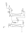
- FIG. 2 shows a configuration example of the acidic gas removal unit 101.
- the acid gas removal unit 101 shown in FIG. 2 employs an amine absorption method.
- NG containing an acidic gas component as an impurity comes into contact with an absorbing solution containing an amine compound in an amine absorption tower 901, and the acidic gas component is separated and removed to remove moisture in the subsequent stage. Sent to the unit 102.
- the absorbing solution that has absorbed the acid gas is heated by the reboiler 903 in the amine regeneration tower 902, dissipates the acid gas, and is sent to the amine absorption tower 901 again.
- the amine regeneration solution released from the bottom of the amine regeneration tower 902 has a high temperature, heat is exchanged in the heat exchanger 906 with the low-temperature acidic gas-absorbing amine solution released from the bottom of the amine absorption tower 901. . Furthermore, since it is necessary to cool the amine regeneration solution to a necessary temperature, the amine regeneration solution is cooled by the amine regeneration solution cooler 907. On the other hand, the acid gas released from the absorption solution is cooled by the regeneration tower top gas condenser 904, gas-liquid separated by the acid gas gas-liquid separation drum 905, and discharged outside the incineration facility or the like.
- the amine regeneration liquid cooler 907 and the regeneration tower top gas condenser 904 are constituted by ACHE6.
- the absorbing fluid and the acidic gas which is a component separated from NG become the fluid to be cooled.
- the layout of the NG liquefying apparatus will be described with reference to FIGS.
- the groups of facilities shown in FIGS. 3 and 4 (equipment groups PL1 and PL2) are arranged and arranged with the pipe rack 600 having a frame structure interposed therebetween.
- the pipe rack 600 supports an assembly of pipes 601 through which components separated and recovered from NG, various refrigerants (C3, MR), an absorption solution used in the acidic gas removal unit 101, and the like flow.
- C3, MR various refrigerants
- absorption solution used in the acidic gas removal unit 101 and the like flow.
- two systems of pipe racks 600 600a, 600b are arranged adjacent to each other in parallel.
- desupermarkets are disposed at the tops of the pipe racks 600 above the aggregate of the pipes 601 in these pipe racks 600.
- ACHEs 6 including heaters 521a, 521b, condensers 522a, 522b, sub-coolers 523a, 523b, amine regeneration solution cooler 907 provided in acid gas removal unit 101, and regeneration tower top gas condenser 904 are arranged. ing.
- the pipe rack 600 is formed in a long and narrow rectangle as viewed from the upper surface side, and the ACHEs 6 are provided, for example, in series along the short side of the rectangle. A large number of sets of three ACHEs 6 are provided along the long side of the rectangle.
- the suction-type ACHE 6 includes a tube bundle 630 in which a group of a plurality of tubes 63 through which a fluid to be cooled (the aforementioned MR, C3 refrigerant, absorption solution, and acid gas) flows, and a fan 62 disposed on the upper side of the tube bundle 630.
- a fluid to be cooled the aforementioned MR, C3 refrigerant, absorption solution, and acid gas
- the tube bundle 630 is open on both upper and lower surfaces so that cooling air can flow from the bottom to the top through the gap between the adjacent tubes 63.
- the opening on the lower surface side of the tube bundle 630 corresponds to an intake port for taking in cooling air, and each ACHE 6 is arranged at the top of the pipe rack 600 with the intake port facing downward. .
- the rotation center of the fan 62 is connected to the upper end portion of the rotation shaft 622 arranged so as to extend upward and downward.
- the lower side of the rotation shaft 622 passes through the tube bundle 630, and the lower end portion thereof is connected to the rotation drive unit 621 disposed below the tube bundle 630.
- the rotation drive unit 621 may be configured by a rotation motor connected to the rotation shaft 622.
- a driving belt is wound around a fan pulley provided at the lower end of the rotating shaft 622 and a motor pulley on the rotating shaft side of the rotating motor disposed on the side of the fan pulley, and the rotating shaft is interposed via the driving belt. It is good also as a structure which rotates 622 (A fan pulley, the rotation motor provided with the motor pulley, and a drive belt are all not shown).
- a discharge flow duct 61 for allowing the air that has passed through the tube bundle 630 to flow is provided in a region from the upper surface of the tube bundle 630 to the side of the fan 62.
- the discharge flow duct 61 gradually decreases in diameter from the lower side toward the upper side, and has a straight tube shape at a side position of the fan 62.
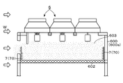
- a floor 602 that partitions the aggregate of the pipes 601 and the ACHE 6 is provided (FIGS. 4 and 5).
- the floor 602 is disposed at a position on the lower side of about 2 to 5 meters from the lower surface side of the tube bundle 630 in which a cooling air intake port is formed.
- a lower space 603 between a large number of ACHEs 6 provided at the top of the pipe rack 600 and the floor 602 is a region through which cooling air taken into each ACHE 6 flows.
- the floor 602 is configured by, for example, grating, and cooling air can be taken from the lower side of the floor 602 toward the lower space 603 formed between the ACHE 6 and the floor 602. Further, the side surface of the pipe rack 600 having a frame structure is in an open state, for example, and cooling air can be taken into the space between the ACHE 6 and the floor 602 from the side surface side.
- the NG liquefying apparatus of this example supplies the mist obtained by spraying demineralized water to the cooling air taken into the ACHE 6 toward the space 603 between the ACHE 6 and the floor 602.
- the mist supply part 7 which cools the cooling air using the vaporization heat is provided.
- the mist supply unit 7 has a structure in which a large number of spray holes 702 for spraying demineralized water toward the space 603 are formed along the extending direction of the water supply pipe 701 through which the demineralized water flows. It has become.
- the mist supply unit 7 of this example is arranged in parallel with the lower side water supply pipe 701a arranged along the floor 602, and in parallel with the lower side water supply pipe 701a, and the lower part of the height from the floor 602 to the intake of the ACHE 6 It is composed of an upper side water supply pipe 701b disposed at a height within a range of about 1/2 to 2/3 of the side, and a side water supply pipe 701c extending in the vertical direction. These water supply pipes 701a to 701c are rectangular. A plurality of sets of mist supply units 70 connected in a shape are connected.
- the particle size of the mist of the desalted water is preferably as small as possible. Therefore, the opening diameter of the spray holes 702 and the supply pressure of the desalted water to the mist supply unit 70 are set so that the spray pressure from each spray hole 702 becomes high. Is done.
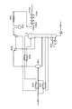
- a mist supply unit 7 formed by connecting a large number of mist supply units 70 is connected to a water supply header 83 via an on-off valve 81 and a flow rate control valve 82 as shown in FIG.
- the upstream side of the water supply header 83 is connected to a desalted water tank 88 via a foreign matter removal filter 84, a flow meter 85, a flow rate adjustment valve 86a, a shutoff valve 86b, a water supply pump 87, and the like.
- desalted water tank 88 for example, desalted water supplied from a not-shown desalted water production apparatus attached to the NG liquefaction apparatus is stored.
- Demineralized water means water from which salts have been removed. Examples thereof include deionized water that has passed through an ion exchange resin, RO (Reverse Osmosis) water that has passed through a reverse osmosis membrane, and distilled water.
- RO Reverse Osmosis
- the mist supply unit 70 constituting the mist supply unit 7 of this example is disposed at a position where the ratio of the mist that reaches the cooling air intake port without being evaporated can be reduced.
- the mist supply unit 70 constituting the mist supply unit 7 includes, for example, the long side and the short side of the pipe rack 600, and the ACHE 6 for each plurality of sets as shown by hatching in FIG. Between the sets, they are arranged along the short side direction. With this configuration, mist can be supplied by spraying demineralized water from the side position toward the lower space 603 between the ACHE 6 and the floor 602, which is upstream of the cooling air suction port. .
- the mist supply unit 7 is arranged along the upper surface of the floor 602 by supplying mist of demineralized water from the mist supply unit 7 provided at a side position of the space 603, and the upper side Compared with the case of spraying demineralized water toward the mist, the mist travel distance from the spray hole 702 to the intake port of ACHE 6 becomes longer. As a result, the ratio of mist that evaporates before reaching the intake port of ACHE 6 increases, and it is possible to suppress the decrease in cooling efficiency and the occurrence of corrosion due to the tube 63 in the tube bundle 630 getting wet with demineralized water. it can.
- the time until the mist sprayed from the spray hole 702 is taken into the intake port is 1 second or longer. It is preferable to adjust the height position where the spray hole 702 is provided so that the mist supply unit 7 (mist supply unit 70) is arranged.
- an NG liquefaction apparatus installed in an area where strong wind blows from a certain direction at a specific time, such as sea breeze, for example, it is provided at a position facing the inflow surface of the wind W in the pipe rack 600a arranged on the windward side.
- a windshield 64 for blocking the wind W flowing into the space 603 may be provided at the intake port of the ACHE 6 (FIG. 5). By providing the windshield 64, it is possible to suppress the cooling air from being swept away by the wind W, and to reliably supply the cooling air cooled by the mist to the end side ACHE 6 as well.
- the spray hole 702 may be opened in a direction in which the desalted water is sprayed in a direction opposite to the direction facing the space 603.
- the spray hole 702 may be opened in a direction in which the desalted water is sprayed in a direction opposite to the direction facing the space 603.
- a movable spray hole 702 in which the direction of spraying mist can be freely changed is provided to the mist supply unit 7, and the direction of spraying the desalted water is changed according to, for example, the strength of the wind W or the wind direction. May be.
- the mist supply unit 7 since the mist supply unit 7 that sprays demineralized water from the side position upstream of the intake port that takes in the ACHE6 cooling air is provided, the mist supply unit 7 It becomes possible to lengthen the moving distance until the mist of demineralized water sprayed from the point reaches the intake port. As a result, the ratio of the mist that reaches the intake port without evaporating is reduced, and the ACHE 6 cooling capacity is improved while suppressing the influence on the equipment due to the AC 63 tube 63 being wetted with demineralized water. Can do.
- FIG. 8 shows a configuration example of an apparatus for efficiently separating components heavier than methane by a method different from the scrub column 2 shown in FIG.
- a cryogenic temperature can be obtained by greatly reducing the operating pressure through the feed gas expander (gas expander) 208, and the NG is cooled using this cold energy.
- the feed gas expander gas expander
- cold heat ⁇ 80 ° C.
- the cold heat from the top of the scrub column 2 is used for cooling NG after being pretreated in the pretreatment section (for example, the acid gas removal section 101, the water removal section 102, and the mercury removal section 103), and NG precooling heat exchange Cool the NG from ⁇ 30 ° C. to ⁇ 40 ° C. through the vessel 205.
- the heavy component that has become liquid is separated by the NG feed gas drum 201, and the heavy component is sent to the lower stage portion of the scrub column 2.
- the gas extracted from the top of the scrub column 2 is subjected to heat exchange and compression operation, and then boosted to a predetermined pressure by the booster compressor 203 and supplied to the MCHE 3.
- a booster compressor after cooler 204 composed of ACHE 6 is provided at the subsequent stage of the booster compressor 203. Therefore, by providing the mist supply unit 7 in the ACHE 6 constituting the booster compressor after cooler 204, it is possible to improve the cooling capacity of the ACHE 6 while suppressing the influence on the equipment due to the tube 63 getting wet with demineralized water. it can. In this case, the gas extracted from the top of the scrub column 2 becomes the fluid to be cooled.
- FIG. 8 a gas processing apparatus for improving the cooling capacity of the ACHE 6 using the mist supply unit 7 for spraying demineralized water from the lateral position to the lower space 603 below the ACHE 6 is shown in FIG. It is not limited to the example of the NG liquefying apparatus shown in FIGS.
- the scrub column 2 shown in FIG. 8 and its peripheral equipment collect liquid heavier than ethane containing condensate from NG, and gas lighter than methane in the state of gas without liquefaction. It can also be used as an NGL (Natural Gas Gas Liquids) device that is shipped to a customer or consumed as fuel gas in the factory.
- NGL Natural Gas Gas Liquids
- NG A GTL (Gas-to-Liquid) apparatus for producing a synthesis gas (a gas containing carbon monoxide and hydrogen as main components) from the synthesis gas and synthesizing a liquid fuel from the synthesis gas can also be mentioned.
- the ACHE6 that cools the synthesis gas obtained from the synthesis gas production process of the GTL (Gas to Liquid) device, the light gas components (hydrogen, carbon monoxide, carbon dioxide, FT) from the FT (Fischer-Tropsch) synthesis reactor
- the mist supply unit 7 of this example can also be provided for the ACHE 6 for cooling methane or the like.
- ACHE6 that cools the synthesis gas obtained from the equipment that produces synthesis gas from NG, methanol synthesis reactor that uses NG and synthesis gas as raw materials, ammonia synthesis reactor, and dimethyl ether direct synthesis
- the mist supply unit 7 of this example can also be applied to the ACHE 6 for cooling the light gas component from the reactor.
- the configuration of the ACHE 6 provided in the gas processing apparatus is not limited to the suction type example illustrated in FIG.
- the mist supply unit 7 of the present example can be applied to the air pushing type ACHE 6 in which the tube bundle 630 is provided on the outlet side of the discharge flow duct 61 and the fan 62 is disposed on the lower side of the tube bundle 630. it can.
- the fan 62, the rotary drive unit 621, and the like By preventing the fan 62, the rotary drive unit 621, and the like from getting wet with the desalted water mist, the occurrence of corrosion of these devices can be suppressed.
- the floor 602 on the lower surface of the lower space 603 where the desalted water is sprayed It is not an essential requirement to provide the floor 602 on the lower surface of the lower space 603 where the desalted water is sprayed.
- the lower space 603 on the lower side of the intake port of the ACHE 6 may be opened toward the space where the aggregate of the pipes 601 is supported.
- the mist supply unit 7 provided in the gas treatment device does not always need to spray demineralized water.
- the mist supply unit 7 is partially or entirely in accordance with the weather. You may provide the timing which stops spraying of demineralized water from.
Landscapes
- Engineering & Computer Science (AREA)
- General Engineering & Computer Science (AREA)
- Mechanical Engineering (AREA)
- Chemical & Material Sciences (AREA)
- Physics & Mathematics (AREA)
- Thermal Sciences (AREA)
- Oil, Petroleum & Natural Gas (AREA)
- General Chemical & Material Sciences (AREA)
- Chemical Kinetics & Catalysis (AREA)
- Organic Chemistry (AREA)
- Analytical Chemistry (AREA)
- Separation By Low-Temperature Treatments (AREA)
- Heat-Exchange Devices With Radiators And Conduit Assemblies (AREA)
Abstract
Description
前記ガス処理装置にて取り扱われる被冷却流体が流れるチューブに対し、取込口を介して取り込んだ冷却用空気を供給し、前記被冷却流体を冷却するための空冷式熱交換器と、
前記空冷式熱交換器に取り込まれる冷却用空気に対し、脱塩水を噴霧して得たミストを供給することにより、前記冷却用空気を冷却するミスト供給部と、を備え、
前記ミスト供給部は、前記取込口の上流側の側方位置から脱塩水の噴霧を行うことを特徴とする。
(a)前記ガス処理装置は、当該ガス処理装置にて取り扱われる流体が流れる配管の集合体を保持する架構構造のパイプラックを備え、前記空冷式熱交換器は、前記取込口を下方側へ向けた状態で前記配管の集合体よりも上方側のパイプラックの頂部に配置され、前記ミスト供給部は、前記取込口が開口する空冷式熱交換器の下方側の空間に向けて、側方側から脱塩水の噴霧を行うこと。
(b)(a)において、前記パイプラックには、前記配管の集合体と空冷式熱交換器との間を区画するフロアが設けられ、前記ミスト供給部からの脱塩水の噴霧は、空冷式熱交換器とフロアとの間の空間に向けて行われること。このとき、前記ミスト供給部は、前記フロアから空冷式熱交換器の取込口までの高さの下部側2/3までの範囲内の高さ位置にて脱塩水の噴霧を行うこと。
(c)(a)において、前記パイプラックは、上面側から見て長方形に構成され、前記空冷式熱交換器は、前記長方形の短辺に沿って直列に複数台並べて設けられ、この複数台の空冷式熱交換器の組が、前記長方形の長辺に沿って複数組並べて設けられていること。このとき、前記ミスト供給部は、前記パイプラックの長辺に沿って設けられていること、さらに前記直列に並べて設けられた複数台の空冷式熱交換器のうち、前記長辺に臨む位置に設けられた空冷式熱交換器の取込口に、前記下方側の空間に流れ込む風を遮るための風防が設けられていること。
(d)(a)において、前記ミスト供給部は、異なる高さ位置にて脱塩水を噴霧する複数の噴霧孔を備えること。異なる高さ位置にて脱塩水を噴霧する前記複数の噴霧孔のうち、一部の噴霧孔は、前記下方側の空間に対向する方向とは反対の方向へ脱塩水を噴霧すること。
図1に示すように、本例のNG液化装置は、予冷用冷媒によってNGを予冷する例えば4段の予冷熱交換器104a~104dと、NGから重質分を分離するスクラブカラム2と、予冷されたNGを液化する極低温主熱交換器(MCHE:Main Cryogenic Heat Exchanger)3と、熱交換後の予冷用冷媒や混合冷媒(以下、MR(Mixed Refrigerant)とも記す)の気体を圧縮する圧縮機41、42、51a(51b)と、を備える。
スクラブカラム2の塔頂側から流出した気体は、MCHE3の最底部にあるNG用のチューブに供給され、MCHE3のシェル側を流れるMRによって冷却される。
高圧MRは、さらにC3冷媒によりチラー431a~431dにて冷却され、気液混合流体として高圧MRセパレーター31へ供給されて気液分離が行われる。
一方、吸収溶液から放散された酸性ガスは、再生塔塔頂ガス凝縮器904にて冷却され、酸性ガス気液分離ドラム905にて気液分離されて焼却設備などの外部へと排出される。
本例のNG液化装置には、2系統のパイプラック600(600a、600b)が、隣り合って並列に配置されている。
ACHE6は、被冷却流体(既述のMR、C3冷媒、吸収溶液や酸性ガス)が流れる多数本のチューブ63の群を束ねたチューブバンドル630と、チューブバンドル630の上方側に配置されたファン62とを備える。
なお、ファン62の数cm~数十cm上方側の高さ位置における放出流ダクト61の開口部内には、開度調節可能なルーバーを設けてもよい。
そこで本例のミスト供給部7を構成するミスト供給ユニット70は、蒸発せずに冷却用空気の取込口に到達するミストの割合を低減することが可能な位置に配置されている。
この場合において、ミスト供給部7に対し、ミストを噴霧する方向が自由に変えられる可動式の噴霧孔702を設け、例えば風Wの強さや風向などに応じて脱塩水を噴霧する方向を変化させてもよい。
図8によれば、フィードガス・エキスパンダー(気体膨張器)208を通して運転圧力を大幅に減圧することにより、極低温を獲得することができ、この冷熱を利用してNGを冷却している。たとえば、60BarのNGをフィードガス・エキスパンダー208にて40Barにまで減圧すると、-80℃の冷熱が得られる。スクラブカラム2の塔頂からの冷熱を、前処理部(例えば酸性ガス除去部101、水分除去部102、水銀除去部103)で前処理された後のNGの冷却に利用し、NG予冷熱交換器205を通してNGを-30℃から-40℃にまで冷却する。液体となった重質成分をNGフィードガスドラム201にて分離し、当該重質成分がスクラブカラム2の低段部に送られる。
このブースターコンプレッサー203の後段にはACHE6により構成されるブースターコンプレッサーアフタークーラー204が設けられている。そこで当該ブースターコンプレッサーアフタークーラー204を構成するACHE6にミスト供給部7を設けることにより、チューブ63が脱塩水で濡れることに伴う機器への影響を抑制しつつ、ACHE6の冷却能力の向上を図ることができる。この場合は、スクラブカラム2の塔頂から抜き出された気体が被冷却流体となる。
600 パイプラック
602 フロア
603 空間
62 ファン
63 チューブ
630 チューブバンドル
7 ミスト供給部
70 ミスト供給ユニット
Claims (9)
- 天然ガスの液化、天然ガス中の成分の分離・回収、天然ガスからの合成ガスの製造、または、天然ガス若しくは前記合成ガスを原料とする化合物の合成の少なくとも一つを行うガス処理装置において、
前記ガス処理装置にて取り扱われる被冷却流体が流れるチューブに対し、取込口を介して取り込んだ冷却用空気を供給し、前記被冷却流体を冷却するための空冷式熱交換器と、
前記空冷式熱交換器に取り込まれる冷却用空気に対し、脱塩水を噴霧して得たミストを供給することにより、前記冷却用空気を冷却するミスト供給部と、を備え、
前記ミスト供給部は、前記取込口の上流側の側方位置から脱塩水の噴霧を行うことを特徴とするガス処理装置。 - 前記ガス処理装置は、当該ガス処理装置にて取り扱われる流体が流れる配管の集合体を保持する架構構造のパイプラックを備え、
前記空冷式熱交換器は、前記取込口を下方側へ向けた状態で前記配管の集合体よりも上方側のパイプラックの頂部に配置され、
前記ミスト供給部は、前記取込口が開口する空冷式熱交換器の下方側の空間に向けて、側方側から脱塩水の噴霧を行うことを特徴とする請求項1に記載のガス処理装置。 - 前記パイプラックには、前記配管の集合体と空冷式熱交換器との間を区画するフロアが設けられ、前記ミスト供給部からの脱塩水の噴霧は、空冷式熱交換器とフロアとの間の空間に向けて行われることを特徴とする請求項2に記載のガス処理装置。
- 前記ミスト供給部は、前記フロアから空冷式熱交換器の取込口までの高さの下部側2/3までの範囲内の高さ位置にて脱塩水の噴霧を行うことを特徴とする請求項3に記載のガス処理装置。
- 前記パイプラックは、上面側から見て長方形に構成され、前記空冷式熱交換器は、前記長方形の短辺に沿って直列に複数台並べて設けられ、この複数台の空冷式熱交換器の組が、前記長方形の長辺に沿って複数組並べて設けられていることを特徴とする請求項2に記載のガス処理装置。
- 前記ミスト供給部は、前記パイプラックの長辺に沿って設けられていることを特徴とする請求項5に記載のガス処理装置。
- 前記直列に並べて設けられた複数台の空冷式熱交換器のうち、前記長辺に臨む位置に設けられた空冷式熱交換器の取込口に、前記下方側の空間に流れ込む風を遮るための風防が設けられていることを特徴とする請求項5に記載のガス処理装置。
- 前記ミスト供給部は、異なる高さ位置にて脱塩水を噴霧する複数の噴霧孔を備えることを特徴とする請求項2に記載のガス処理装置。
- 異なる高さ位置にて脱塩水を噴霧する前記複数の噴霧孔のうち、一部の噴霧孔は、前記下方側の空間に対向する方向とは反対の方向へ脱塩水を噴霧することを特徴とする請求項8に記載のガス処理装置。
Priority Applications (4)
| Application Number | Priority Date | Filing Date | Title |
|---|---|---|---|
| AU2016401829A AU2016401829B2 (en) | 2016-04-08 | 2016-04-08 | Gas processing facility |
| US16/091,530 US10823500B2 (en) | 2016-04-08 | 2016-04-08 | Gas processing facility |
| MYPI2018703625A MY199041A (en) | 2016-04-08 | 2016-04-08 | Gas processing facility |
| PCT/JP2016/061555 WO2017175384A1 (ja) | 2016-04-08 | 2016-04-08 | ガス処理装置 |
Applications Claiming Priority (1)
| Application Number | Priority Date | Filing Date | Title |
|---|---|---|---|
| PCT/JP2016/061555 WO2017175384A1 (ja) | 2016-04-08 | 2016-04-08 | ガス処理装置 |
Publications (1)
| Publication Number | Publication Date |
|---|---|
| WO2017175384A1 true WO2017175384A1 (ja) | 2017-10-12 |
Family
ID=60000970
Family Applications (1)
| Application Number | Title | Priority Date | Filing Date |
|---|---|---|---|
| PCT/JP2016/061555 Ceased WO2017175384A1 (ja) | 2016-04-08 | 2016-04-08 | ガス処理装置 |
Country Status (4)
| Country | Link |
|---|---|
| US (1) | US10823500B2 (ja) |
| AU (1) | AU2016401829B2 (ja) |
| MY (1) | MY199041A (ja) |
| WO (1) | WO2017175384A1 (ja) |
Cited By (5)
| Publication number | Priority date | Publication date | Assignee | Title |
|---|---|---|---|---|
| JP6360987B1 (ja) * | 2017-11-14 | 2018-07-18 | 日揮株式会社 | 天然ガス液化装置、及び天然ガス液化装置の設計方法 |
| WO2019159371A1 (ja) * | 2018-02-19 | 2019-08-22 | 日揮株式会社 | 天然ガス液化装置 |
| JP2020514666A (ja) * | 2017-03-16 | 2020-05-21 | テクニップ フランス | 水域の表面に配置される天然ガス液化装置、及び関連する冷却方法 |
| WO2020188805A1 (ja) * | 2019-03-20 | 2020-09-24 | 日揮グローバル株式会社 | 熱交換器群の設計方法及び処理プラント |
| WO2021255876A1 (ja) * | 2020-06-17 | 2021-12-23 | 日揮グローバル株式会社 | 天然ガス液化装置 |
Families Citing this family (2)
| Publication number | Priority date | Publication date | Assignee | Title |
|---|---|---|---|---|
| WO2022137296A1 (ja) * | 2020-12-21 | 2022-06-30 | 日揮グローバル株式会社 | 複合天然ガス処理システム |
| CN114111368A (zh) * | 2021-10-25 | 2022-03-01 | 国网河北省电力有限公司电力科学研究院 | 一种空冷岛挡风墙系统及空冷岛 |
Citations (2)
| Publication number | Priority date | Publication date | Assignee | Title |
|---|---|---|---|---|
| WO2015115030A1 (en) * | 2014-01-31 | 2015-08-06 | Jgc Corporation | Liquefied gas producing facility and liquefied gas producing method |
| WO2016001952A1 (ja) * | 2014-07-02 | 2016-01-07 | 日揮株式会社 | 空冷式液化ガス製造設備 |
Family Cites Families (11)
| Publication number | Priority date | Publication date | Assignee | Title |
|---|---|---|---|---|
| US3830196A (en) * | 1971-08-31 | 1974-08-20 | Nat Steel Corp | Cleaning paint hooks |
| US4425142A (en) * | 1982-11-15 | 1984-01-10 | Chicago Bridge & Iron Company | Pressure swing adsorption cycle for natural gas pretreatment for liquefaction |
| US5925291A (en) * | 1997-03-25 | 1999-07-20 | Midwest Research Institute | Method and apparatus for high-efficiency direct contact condensation |
| US7765827B2 (en) * | 2005-11-08 | 2010-08-03 | Everest Acquisition Holdings, Inc. | Multi-stage hybrid evaporative cooling system |
| US20090165435A1 (en) * | 2008-01-02 | 2009-07-02 | Michal Koranek | Dual fuel can combustor with automatic liquid fuel purge |
| US8708065B2 (en) * | 2009-06-03 | 2014-04-29 | National Oilwell Varco, L.P. | Vessel to condition dry drill cuttings |
| US9243847B2 (en) * | 2009-11-04 | 2016-01-26 | Evapco, Inc. | Hybrid heat exchange apparatus |
| JP5773756B2 (ja) * | 2011-05-31 | 2015-09-02 | 三菱日立パワーシステムズ株式会社 | 脱水濾液の噴霧乾燥装置及び排ガス処理システム |
| US10016717B2 (en) * | 2014-11-06 | 2018-07-10 | Exxonmobil Upstream Research Company | Adsorbing contaminants from a gas stream |
| WO2017053820A1 (en) * | 2015-09-23 | 2017-03-30 | Composite Cooling Solutions, L.P. | Hybrid wet/dry cooling tower and improved fill material for cooling tower |
| WO2017120603A1 (en) * | 2016-01-08 | 2017-07-13 | Evapco, Inc. | Improvement of thermal capacity of elliptically finned heat exchanger |
-
2016
- 2016-04-08 MY MYPI2018703625A patent/MY199041A/en unknown
- 2016-04-08 WO PCT/JP2016/061555 patent/WO2017175384A1/ja not_active Ceased
- 2016-04-08 AU AU2016401829A patent/AU2016401829B2/en active Active
- 2016-04-08 US US16/091,530 patent/US10823500B2/en active Active
Patent Citations (2)
| Publication number | Priority date | Publication date | Assignee | Title |
|---|---|---|---|---|
| WO2015115030A1 (en) * | 2014-01-31 | 2015-08-06 | Jgc Corporation | Liquefied gas producing facility and liquefied gas producing method |
| WO2016001952A1 (ja) * | 2014-07-02 | 2016-01-07 | 日揮株式会社 | 空冷式液化ガス製造設備 |
Cited By (15)
| Publication number | Priority date | Publication date | Assignee | Title |
|---|---|---|---|---|
| JP2020514666A (ja) * | 2017-03-16 | 2020-05-21 | テクニップ フランス | 水域の表面に配置される天然ガス液化装置、及び関連する冷却方法 |
| JP7061133B2 (ja) | 2017-03-16 | 2022-04-27 | テクニップ フランス | 水域の表面に配置される天然ガス液化装置、及び関連する冷却方法 |
| WO2019097571A1 (ja) * | 2017-11-14 | 2019-05-23 | 日揮株式会社 | 天然ガス液化装置、及び天然ガス液化装置の設計方法 |
| RU2736122C1 (ru) * | 2017-11-14 | 2020-11-11 | ДжГК Корпорейшн | Устройство для сжижения природного газа и способ проектирования устройства для сжижения природного газа |
| JP6360987B1 (ja) * | 2017-11-14 | 2018-07-18 | 日揮株式会社 | 天然ガス液化装置、及び天然ガス液化装置の設計方法 |
| RU2751049C9 (ru) * | 2018-02-19 | 2022-04-26 | ДжГК Корпорейшн | Установка для сжижения природного газа |
| WO2019159371A1 (ja) * | 2018-02-19 | 2019-08-22 | 日揮株式会社 | 天然ガス液化装置 |
| RU2751049C1 (ru) * | 2018-02-19 | 2021-07-07 | ДжГК Корпорейшн | Установка для сжижения природного газа |
| JP6799726B1 (ja) * | 2019-03-20 | 2020-12-16 | 日揮グローバル株式会社 | 熱交換器群の設計方法及び処理プラント |
| KR20210131340A (ko) * | 2019-03-20 | 2021-11-02 | 닛키 글로벌 가부시키가이샤 | 열교환기 그룹의 설계 방법 및 처리 플랜트 |
| WO2020188805A1 (ja) * | 2019-03-20 | 2020-09-24 | 日揮グローバル株式会社 | 熱交換器群の設計方法及び処理プラント |
| EP3943859A4 (en) * | 2019-03-20 | 2022-10-12 | JGC Corporation | PROCEDURE FOR DESIGNING A HEAT EXCHANGER GROUP AND TREATMENT PLANT |
| US11879687B2 (en) | 2019-03-20 | 2024-01-23 | Jgc Corporation | Method of designing heat exchanger group and processing plant |
| KR102628779B1 (ko) | 2019-03-20 | 2024-01-24 | 닛키 글로벌 가부시키가이샤 | 열교환기 그룹의 설계 방법 및 처리 플랜트 |
| WO2021255876A1 (ja) * | 2020-06-17 | 2021-12-23 | 日揮グローバル株式会社 | 天然ガス液化装置 |
Also Published As
| Publication number | Publication date |
|---|---|
| AU2016401829B2 (en) | 2022-05-12 |
| US20190128599A1 (en) | 2019-05-02 |
| US10823500B2 (en) | 2020-11-03 |
| AU2016401829A1 (en) | 2018-10-18 |
| MY199041A (en) | 2023-10-11 |
Similar Documents
| Publication | Publication Date | Title |
|---|---|---|
| WO2017175384A1 (ja) | ガス処理装置 | |
| CN1144999C (zh) | 对富含甲烷的气流进行液化的方法 | |
| AU2006215629B2 (en) | Plant and method for liquefying natural gas | |
| RU2668303C1 (ru) | Система и способ для сжижения природного газа (варианты) | |
| RU2716099C1 (ru) | Модульное устройство для отделения спг и теплообменник газа мгновенного испарения | |
| CN1323386A (zh) | 常规气态物质向液体产品的转化 | |
| US10502484B2 (en) | System and method for liquefying natural gas with turbine inlet cooling | |
| RU2736122C1 (ru) | Устройство для сжижения природного газа и способ проектирования устройства для сжижения природного газа | |
| US20180045459A1 (en) | Method for liquefying a hydrocarbon-rich fraction | |
| US20180051929A1 (en) | System and Method to Integrate Condensed Water with Improved Cooler Performance | |
| WO2016103295A1 (ja) | 冷凍装置 | |
| WO2017125965A1 (ja) | 天然ガス処理装置 | |
| RU2747304C2 (ru) | Установка для редуцирования газа и выработки спг | |
| Arinelli et al. | Supersonic Separators for Offshore Processing of CO2-Rich Natural Gas: Comparison with Conventional Routes |
Legal Events
| Date | Code | Title | Description |
|---|---|---|---|
| NENP | Non-entry into the national phase |
Ref country code: DE |
|
| ENP | Entry into the national phase |
Ref document number: 2016401829 Country of ref document: AU Date of ref document: 20160408 Kind code of ref document: A |
|
| 121 | Ep: the epo has been informed by wipo that ep was designated in this application |
Ref document number: 16897940 Country of ref document: EP Kind code of ref document: A1 |
|
| 122 | Ep: pct application non-entry in european phase |
Ref document number: 16897940 Country of ref document: EP Kind code of ref document: A1 |
|
| NENP | Non-entry into the national phase |
Ref country code: JP |