WO2017169620A1 - 触媒コンバーターおよび触媒コンバーターの製造方法 - Google Patents
触媒コンバーターおよび触媒コンバーターの製造方法 Download PDFInfo
- Publication number
- WO2017169620A1 WO2017169620A1 PCT/JP2017/009436 JP2017009436W WO2017169620A1 WO 2017169620 A1 WO2017169620 A1 WO 2017169620A1 JP 2017009436 W JP2017009436 W JP 2017009436W WO 2017169620 A1 WO2017169620 A1 WO 2017169620A1
- Authority
- WO
- WIPO (PCT)
- Prior art keywords
- fiber
- catalytic converter
- catalyst carrier
- casing
- catalyst
- Prior art date
- Legal status (The legal status is an assumption and is not a legal conclusion. Google has not performed a legal analysis and makes no representation as to the accuracy of the status listed.)
- Ceased
Links
Images
Classifications
-
- B—PERFORMING OPERATIONS; TRANSPORTING
- B01—PHYSICAL OR CHEMICAL PROCESSES OR APPARATUS IN GENERAL
- B01D—SEPARATION
- B01D53/00—Separation of gases or vapours; Recovering vapours of volatile solvents from gases; Chemical or biological purification of waste gases, e.g. engine exhaust gases, smoke, fumes, flue gases, aerosols
- B01D53/34—Chemical or biological purification of waste gases
- B01D53/92—Chemical or biological purification of waste gases of engine exhaust gases
- B01D53/94—Chemical or biological purification of waste gases of engine exhaust gases by catalytic processes
-
- F—MECHANICAL ENGINEERING; LIGHTING; HEATING; WEAPONS; BLASTING
- F01—MACHINES OR ENGINES IN GENERAL; ENGINE PLANTS IN GENERAL; STEAM ENGINES
- F01N—GAS-FLOW SILENCERS OR EXHAUST APPARATUS FOR MACHINES OR ENGINES IN GENERAL; GAS-FLOW SILENCERS OR EXHAUST APPARATUS FOR INTERNAL-COMBUSTION ENGINES
- F01N3/00—Exhaust or silencing apparatus having means for purifying, rendering innocuous, or otherwise treating exhaust
- F01N3/08—Exhaust or silencing apparatus having means for purifying, rendering innocuous, or otherwise treating exhaust for rendering innocuous
- F01N3/10—Exhaust or silencing apparatus having means for purifying, rendering innocuous, or otherwise treating exhaust for rendering innocuous by thermal or catalytic conversion of noxious components of exhaust
- F01N3/24—Exhaust or silencing apparatus having means for purifying, rendering innocuous, or otherwise treating exhaust for rendering innocuous by thermal or catalytic conversion of noxious components of exhaust characterised by constructional aspects of converting apparatus
- F01N3/28—Construction of catalytic reactors
Definitions
- the present invention relates to a catalytic converter and a method for manufacturing the catalytic converter.
- Vehicles such as automobiles are loaded with exhaust gas purifying catalytic converters in order to remove harmful components such as carbon monoxide, hydrocarbons and nitrogen oxides contained in the exhaust gas of the engine.
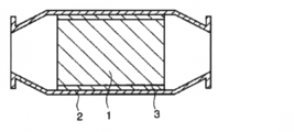
- a catalytic converter is generally mounted on a catalyst carrier 1 that is formed in a cylindrical shape, a metal casing 2 that accommodates the catalyst carrier 1, and a catalyst carrier 1, as shown in a sectional view in FIG.
- the holding member 3 is interposed in the gap between the catalyst carrier 1 and the casing 2.
- the catalyst carrier 1 for example, a noble metal catalyst or the like supported on a cylindrical honeycomb formed body made of, for example, cordierite is generally used. Therefore, the catalyst carrier 1 is held in the gap between the catalyst carrier 1 and the casing 2.
- the material 3 has high-temperature heat resistance, a function of safely holding the catalyst carrier 1 so that the catalyst carrier 1 does not collide with the casing 2 due to vibration or the like during driving of the automobile, and the catalyst carrier 1 and the casing. 2 is required to have a function of sealing so that unpurified exhaust gas does not leak from the gap (see, for example, Patent Document 1 (Japanese Patent Laid-Open No. 2003-286837)).
- Patent Document 1 Japanese Patent Laid-Open No. 2003-286837
- the alumina fiber constituting the catalyst converter holding material is excellent in heat resistance and elastic recovery, when used as a material for the catalyst converter holding material, it has excellent catalyst carrier holding performance and exhaust gas sealing performance. It can be demonstrated.
- ceramic fibers such as alumina fibers excellent in heat resistance and the like have been indispensable as a constituent material of a holding material for catalytic converters used at high temperatures.
- ceramic fibers such as alumina fibers are generally expensive, it is generally easy to increase the cost of the holding material for the catalytic converter.
- the catalytic converter holding material is used for a long period of time, it is easily eroded (wind eroded) by the unpurified exhaust gas, and the catalyst carrier is easily deteriorated in the casing. Therefore, it is easy to reduce the sealability and the like, and therefore, it is difficult to be affected by such erosion and has excellent durability and excellent catalytic converter retention.
- the present invention provides a catalytic converter that has excellent heat resistance, can exhibit excellent durability even when used for a long period of time, and has excellent retention of a catalyst carrier that can be manufactured at low cost, and the catalytic converter
- An object of the present invention is to provide a manufacturing method.
- a catalyst carrier In order to achieve the above object, as a result of intensive studies by the present inventors, a catalyst carrier, a casing for housing the catalyst carrier, a catalyst converter holding material disposed between the catalyst carrier and the casing,
- the catalytic converter holding material includes a skeletal fiber composed of one or more fibers selected from alumina fiber, mullite fiber, alumina silicate fiber, silica fiber and biosoluble fiber, and has at least one main surface It consists of a fiber assembly in which a glass melt is dispersed in a surface layer portion, and the skeletal fiber constituting the catalyst converter holding material is inserted through the glass melt at the interface with the casing or the interface with the catalyst carrier.
- the above technical section is provided by a catalytic converter fixed to at least one of the casing and the catalyst carrier. It found that it is possible to solve, and completed the present invention based on this finding.
- the present invention (1) including a catalyst carrier, a casing for housing the catalyst carrier, and a catalyst converter holding material disposed between the catalyst carrier and the casing
- the catalytic converter holding material includes a skeletal fiber composed of one or more fibers selected from alumina fiber, mullite fiber, alumina silicate fiber, silica fiber, and biosoluble fiber, and at least on the surface layer portion of one main surface It consists of a fiber assembly in which glass melt is dispersed, Skeletal fibers constituting the catalytic converter holding material are fixed to at least one of the casing and the catalyst carrier via the glass melt at the interface with the casing or the interface with the catalyst carrier.
- a catalytic converter characterized by (2) including a catalyst carrier, a casing for housing the catalyst carrier, and a catalyst converter holding material disposed between the catalyst carrier and the casing,
- the catalytic converter holding material includes a skeletal fiber composed of one or more fibers selected from alumina fiber, mullite fiber, alumina silicate fiber, silica fiber, and biosoluble fiber, and at least on the surface layer portion of one main surface It consists of a fiber assembly in which glass melt is dispersed,
- the skeleton fiber constituting the catalyst converter holding material is fixed to both the casing and the catalyst carrier via the glass melt at the interface with the casing and the interface with the catalyst carrier.
- the catalytic converter according to (1) (3) A method for producing the catalytic converter according to (1) above, A coating containing glass powder on the surface layer of at least one main surface of a fiber assembly including a skeleton fiber composed of one or more fibers selected from alumina fiber, mullite fiber, alumina silicate fiber, silica fiber and biosoluble fiber After spraying or applying the liquid to obtain a surface wet product, Heat treatment at a temperature equal to or higher than the softening point of the glass constituting the glass powder in a state in which the surface-humidified product or the dried product of the surface-humidified material is disposed in the gap between the catalyst carrier and the casing containing the catalyst carrier.
- a process for producing a catalytic converter characterized in that (4) A method for producing the catalytic converter according to (2) above, A coating liquid containing glass powder is sprayed on the surface layer portions of both main surfaces of a fiber assembly including a skeleton fiber composed of one or more fibers selected from alumina fiber, mullite fiber, alumina silicate fiber, silica fiber and biosoluble fiber. Or after applying to obtain a surface wet product, Heat treatment at a temperature equal to or higher than the softening point of the glass constituting the glass powder in a state in which the surface-humidified product or the dried product of the surface-humidified material is disposed in the gap between the catalyst carrier and the casing containing the catalyst carrier. Manufacturing method of catalytic converter,
- the holding material constituting the catalytic converter is made of the glass melt so that the skeletal fiber is fixed to the casing at the interface with the casing, or the skeletal fiber is fixed to the catalyst support at the interface with the catalyst carrier.
- the holding material and casing or the holding material and the catalyst carrier are firmly bound to each other, thereby exhibiting excellent durability. can do. Therefore, according to the present invention, a catalytic converter that has excellent heat resistance, can exhibit excellent durability even when used for a long time, and has excellent retention of a catalyst carrier that can be manufactured at low cost, and A method for producing the catalytic converter can be provided.
- the catalytic converter according to the present invention includes a casing that houses the catalyst carrier, and a catalyst converter holding material disposed between the catalyst carrier and the casing, and the catalyst converter holding material includes alumina fibers and mullite fibers.
- a skeleton fiber composed of one or more fibers selected from alumina silicate fiber, silica fiber and biosoluble fiber, and comprising a fiber assembly in which a glass melt is dispersed in the surface layer part of at least one main surface,
- the skeletal fiber constituting the holding material for the catalytic converter is fixed to at least one of the casing and the catalyst carrier via the glass melt at the interface with the casing or the interface with the catalyst carrier. It is characterized by.
- the supporting material for the catalytic converter is, as a skeleton fiber, 1) alumina fiber, (2) mullite fiber, (3) alumina silicate fiber, (4) silica fiber, and (5) biosoluble fiber. Or two or more selected from the above-mentioned fibers.
- the alumina fiber means an amorphous fiber or a polycrystalline fiber mainly composed of alumina (Al 2 O 3 ), and the alumina (Al 2 O 3 ) is 90 to 99 mass. %, 1 to 10% by mass of SiO 2 is preferred, 95 to 99% by mass of Al 2 O 3 and 1 to 5% by mass of SiO 2 are more preferred, and 97% of Al 2 O 3 is preferred. More preferably, it contains ⁇ 99 mass% and SiO 2 contains 1 to 3 mass%.
- a mullite fiber, alumina (Al 2 O 3) and silica refers to amorphous fibers or polycrystalline fibers as a main component (SiO 2), the Al 2 O 3 60 to 90% by weight, it is preferred those containing SiO 2 10 - 40 wt%, the Al 2 O 3 70 ⁇ 85 wt%, those containing SiO 2 15 - 30 wt% is more preferable, Al 2 O 3 72 to 80 wt%, those containing SiO 2 20 ⁇ 28 mass% is more preferable.
- the alumina silicate fibers means amorphous fibers or polycrystalline fibers mainly composed of alumina (Al 2 O 3) and silica (SiO 2), the Al 2 O 3
- a material containing 30 to 60% by mass, 40 to 70% by mass of SiO 2 is preferable, a compound containing 35 to 60% by mass of Al 2 O 3 and 40 to 65% by mass of SiO 2 is more preferable, and Al 2 More preferred are those containing 40 to 60% by mass of O 3 and 40 to 60% by mass of SiO 2 .
- the silica fiber means an amorphous fiber or a polycrystalline fiber containing silica (SiO 2 ) as a main component, Al 2 O 3 being 1 to 20% by mass, and SiO 2 being A material containing 80 to 99% by mass is preferable, Al 2 O 3 is contained in an amount of 1 to 10% by mass, SiO 2 Those containing 90 to 99% by mass of 2 are more preferable, and those containing 1 to 5% by mass of Al 2 O 3 and 95 to 99% by mass of SiO 2 are more preferable.
- the biosoluble fiber is not particularly limited as long as it is an inorganic fiber having solubility (degradability) that is decomposed in vivo, but is artificially imparted with in vivo solubility.
- An amorphous inorganic fiber can be mentioned, for example, an inorganic fiber having a dissolution rate in physiological saline at 40 ° C. of 1% by mass or more and a heat shrinkage rate of 5% or less when heated at 1000 ° C. for 8 hours. Is preferred.
- the dissolution rate in the said physiological saline shall mean the value measured with the following method. That is, first, 1 g of a sample prepared by pulverizing a biosoluble fiber to 200 mesh or less and 150 mL of physiological saline were placed in an Erlenmeyer flask (volume: 300 mL), placed in an incubator at 40 ° C., and then placed in each Erlenmeyer flask. Filtration is performed by applying horizontal vibration for 50 hours at 120 rpm, and then the elements contained in the filtrate are quantified with an ICP emission spectrometer.
- the solubility representing the ratio of the amount of the element eluted from the sample before the test into the filtrate (the weight reduction rate of the sample by dissolution) is obtained be able to.
- the skeletal fibers constituting the catalyst converter holding material preferably have an average length of 0.1 to 20 mm, more preferably 0.1 to 10 mm, and even more preferably 0.1 to 5 mm.
- the average length of the skeleton fiber means an arithmetic average value when the length of 100 skeleton fibers is measured with an optical microscope.
- the skeletal fibers constituting the catalyst converter holding material are preferably monofilaments or multifilaments.
- the fiber assembly means that a large number of fibers are entangled with each other and formed into a certain form such as a plate shape or a sheet shape, and the fiber assembly constituting the holding material for the catalytic converter.
- the body is preferably in the form of a fabric in which fibers including skeletal fibers are arranged at random, in one direction or alternately, a fabric such as a knitted fabric, a nonwoven fabric, or a mat such as a needle mat.
- the glass melt is dispersed in the surface layer portion of at least one main surface of the fiber assembly (which constitutes the holding material for the catalytic converter).
- the glass melt can be appropriately selected from those having a softening point lower than the melting point of the skeletal fiber, and a glass melt having a softening point of 300 to 1000 ° C. It is preferably a glass melt having a softening point of 500 to 1000 ° C., and more preferably a glass melt having a softening point of 700 to 1000 ° C. In the holding material for a catalytic converter according to the present invention, the glass melt is more preferably a glass powder melt having the softening point.
- Examples of the glass having the softening point include those containing one or more kinds selected from oxides such as Si, Al, Zn, and alkaline earth metals.
- the glass powder when the glass melt is a glass powder melt, the glass powder preferably has an average particle diameter D50 of 0.1 to 1000 ⁇ m, preferably 0.5 to 100 ⁇ m. More preferred are those having a diameter of 1 to 10 ⁇ m. As such a glass powder, one having a desired particle diameter may be appropriately selected from those commercially available as glass frit.
- the average particle diameter D50 of a glass powder means the particle size of 50% by the integrated particle size in a volume reference
- the holding material for the catalytic converter is 50 to 99.99% by mass in a dry state when the total amount of the skeleton fiber and the glass powder is 100 parts by mass. It is preferably contained, more preferably 90 to 99.99% by mass, and even more preferably 98 to 99.99% by mass.
- the support material for the catalytic converter includes, for example, alumina fibers and biosoluble fibers as the skeleton fibers, 1 to 99 mass% of the alumina fibers when the total amount of the skeleton fibers is 100 mass% in a dry state, It is preferable to contain 1 to 99% by mass of biosoluble fiber, 20 to 80% by mass of alumina fiber, more preferably 20 to 80% by mass of biosoluble fiber, 40 to 60% by mass of alumina fiber, More preferably, the soluble fiber is contained in an amount of 40 to 60% by mass.
- the catalytic converter holding material preferably contains 0.01 to 50% by mass, more preferably 0.01 to 10% by mass of the above glass melt in a dry state. More preferably, the content is 2% by mass.
- the holding material for the catalytic converter contains the skeletal fiber and the glass melt at the above ratios, excellent heat resistance and durability can be easily exhibited.
- the holding material for the catalytic converter is one or more binders selected from an organic binder and an inorganic binder as necessary within the range where the effects of the present invention are exhibited, together with the skeleton fiber and the glass melt in the fiber assembly. Etc. may be included.
- the holding material for the catalytic converter preferably contains 80 to 100% by mass, more preferably 85 to 99% by mass, in total, of the skeletal fibers and the glass melt in the dry state during fiber assembly. More preferably, the content is 98% by mass.
- the content ratio of the components other than the skeleton fiber and the glass melt in the fiber assembly is suitably 0 to 20% by mass in a dry state, and 1 to 15% by mass. % Is more appropriate, and 2 to 10% by mass is even more appropriate.
- the fiber assembly means that a large number of fibers are intertwined with each other and formed into a certain form such as a plate shape or a sheet shape.
- the thickness of the fiber assembly constituting the catalyst converter holding material is preferably 5 to 20 mm, more preferably 6 to 15 mm, and even more preferably 7 to 10 mm.
- the fiber assembly constituting the catalyst converter holding material preferably has a bulk density of 0.10 to 0.30 g / cm 3 , more preferably 0.13 to 0.25 g / cm 3. Preferably, it is 0.15 to 0.20 g / cm 3 .
- the thickness and bulk density of the fiber assembly constituting the catalyst converter holding material are within the above ranges, so that it is easy to provide a catalyst converter holding material with excellent workability and excellent elastic modulus and strength. can do.
- the shape of the catalyst converter holding material is not particularly limited, and may be a plate shape or a sheet shape, or may have a shape corresponding to the outer shape of the catalyst carrier to be disposed.
- a glass melt is dispersed in the surface layer portion of at least one main surface of the fiber assembly including the skeleton fiber in the holding material for the catalytic converter.
- the surface layer portion of the fiber assembly refers to the catalyst carrier or the casing when the holding material for the catalytic converter is disposed in the gap between the catalyst carrier and the casing containing the catalyst carrier in the fiber assembly. Usually, it means from the main surface (outermost surface) to a depth of about 1 mm.
- the casing is not particularly limited as long as it can accommodate the catalyst carrier and the catalyst converter holding material therein.
- the form of the casing is not particularly limited, but preferably has a shape corresponding to the shape of the catalyst carrier.
- the shape of the casing is also preferably a cylindrical shape.
- the casing is cylindrical, for example, it may be a pair of upper and lower parts composed of a half-shaped upper casing and a half-shaped lower casing obtained by halving the cylindrical casing.
- the constituent material of the casing is not particularly limited as long as it has desired heat resistance, and is appropriately selected from known ones. Usually, it is appropriately selected from those made of metal such as stainless steel and iron.
- the skeletal fiber and the casing constituting the holding material for the catalytic converter are fixed by a glass melt, or the skeleton fiber and the catalyst carrier are fixed by a glass melt, preferably In this case, both the skeletal fiber constituting the holding material for the catalytic converter, the casing, and the catalyst carrier are fixed by a glass melt.
- the support material for the catalytic converter has an excellent heat resistance because the inexpensive glass melt is dispersed in the surface layer portion of at least one main surface of the fiber assembly including the skeleton fiber.
- the holding material is firmly fixed and excellent durability can be exhibited.
- the present invention it is possible to provide a catalytic converter that has excellent heat resistance, can exhibit excellent durability even when used for a long period of time, and has excellent retainability that can be manufactured at low cost. Can do.
- the catalytic converter according to the present invention can be suitably manufactured, for example, by the following method for manufacturing a catalytic converter according to the present invention.
- the method for producing a catalytic converter according to the present invention is at least one of a fiber assembly including a skeleton fiber composed of at least one fiber selected from alumina fiber, mullite fiber, alumina silicate fiber, silica fiber, and biosoluble fiber.
- a coating liquid containing glass powder After spraying or applying a coating liquid containing glass powder on the surface layer of the main surface of the surface to obtain a surface wetted product, the surface wetted product or the dried product of the surface wetted product is used as the catalyst support and the catalyst support.
- the heat treatment is performed at a temperature equal to or higher than the softening point of the glass constituting the glass powder in a state of being disposed in a gap with the casing to be accommodated.
- the details of the skeletal fiber and the glass powder are as described above.
- 0.01 to 50 parts by mass of the glass powder is preferably sprayed or applied to 100 parts by mass of the skeletal fiber, and 0.01 to 10 parts by mass of the glass powder is added. It is more preferable to spray or apply, and it is more preferable to spray or apply 0.01 to 2 parts by mass of the glass powder.
- the coating liquid preferably has a glass powder content of 0.1 to 100% by mass, more preferably 0.1 to 5% by mass, and 0.1 to 10% by mass. Further preferred.
- the glass powder in order to form a coating solution, may be added to a solvent, and a binder such as an organic binder may be added to the solvent.
- organic binder examples include one or more selected from starch, a polymer flocculant, pulp, and an appropriate emulsion.
- the type and amount of the organic binder added to the solvent may be appropriately selected.
- the organic binder may be added to the solvent in the form of a solid, or may be added in the form of a suspension or a solution.
- the coating liquid preferably contains 0 to 20 parts by mass of an organic binder with respect to 100 parts by mass of the skeletal fibers contained in the coating liquid, and preferably contains 1 to 15 parts by mass. More preferably, it is more preferably 2 to 10 parts by mass.
- glass powder can be suitably attached to the surface layer portion of the surface wet product obtained by using the organic binder.
- the solvent used in forming the coating liquid is not particularly limited, and examples thereof include water and polar organic solvents.
- water include distilled water, ion-exchanged water, tap water, ground water, and industrial water.
- polar organic solvents include monovalent alcohols such as ethanol and propanol, and divalents such as ethylene glycol. Can be mentioned.
- water is preferable in that the working environment is not deteriorated and there is no burden on the environment.
- the total solid content concentration contained in the coating liquid is preferably 0.05 to 5% by mass, more preferably 0.1 to 2% by mass, and preferably 0.2 to 1% by mass. Further preferred.
- the total solid content concentration contained in the coating liquid is less than 0.05% by mass, the amount of the solvent to be removed after spraying or coating the coating liquid is excessively increased, so that the production efficiency is easily lowered.
- it exceeds mass% it will become difficult to disperse
- a surface-humidified product is obtained by spraying or applying the coating liquid to the fiber assembly.
- a method for spraying or applying the coating liquid a known method can be appropriately selected.
- a method such as spraying, roller coating, or dipping may be appropriately selected.
- There are no particular restrictions on the spraying or coating conditions of the coating liquid, and conditions for allowing a desired amount of glass powder to adhere to the surface of the fiber assembly may be appropriately selected.
- the surface moistened product is suitably one having a shape similar to the catalyst converter holding material to be obtained, and examples thereof include a plate shape, a sheet shape, and a shape corresponding to the outer shape of the catalyst carrier.
- the surface-humidified product may be pressed as necessary.
- the surface wet product obtained by the above method is appropriately subjected to a drying treatment.
- the drying treatment can be performed with a known dryer or the like, and the drying temperature is preferably 50 to 300 ° C, more preferably 100 to 250 ° C, and further preferably 150 to 200 ° C.
- the drying time is preferably 1 to 60 minutes, more preferably 1 to 30 minutes, and further preferably 1 to 10 minutes.
- a surface moistened product or a dried product having a desired shape may be obtained by further performing a processing treatment such as a punching treatment if necessary.
- the glass powder is placed in a state where the surface wetted product or the dried product of the surface wetted product is disposed in a gap between the catalyst support and a casing containing the catalyst support.
- Heat treatment is performed at a temperature equal to or higher than the softening point of the glass.
- the above arrangement is performed by appropriately winding the wet molded body or the dried product of the wet molded body around the cylindrical catalyst carrier, and then mounting the cylindrical casing. It can be carried out by accommodating in a halved lower casing, and then stacking an upper casing that is also a halved cylindrical casing and joining them with bolts or the like to form a cylindrical object.
- the heat treatment can be performed in a known heating furnace, and the heating temperature is not particularly limited as long as the glass powder is melted, but is preferably 300 to 1100 ° C., more preferably 700 to 1000 ° C.
- the heating time is preferably 1 to 60 minutes, more preferably 1 to 30 minutes, and further preferably 1 to 10 minutes.
- the surface-humidified product or the dried product of the surface-humidified product is disposed in a gap between the catalyst carrier and a casing containing the catalyst carrier to form a catalytic converter, and further disposed in the automobile.
- the heat treatment may be performed by the combustion heat of the fuel generated by driving the engine in the state.
- the glass powder is melted to become a glass melt, and the glass melt adheres the skeletal fiber and the casing at the interface with the casing, or the skeletal fiber and the catalyst at the interface with the catalyst carrier. It is possible to provide a catalytic converter excellent in durability by fixing the carrier to improve the strength of the skeletal fiber and highly suppressing the displacement of the skeletal fiber.
- Example 1 Forming material for holding material for catalytic converter 100 parts by mass of alumina fiber (Al 2 O 3 content ratio 96 mass%, SiO 2 content ratio 4 mass%) as a skeleton fiber and 10 mass parts of acrylic resin as an organic binder
- An aqueous slurry (solid content concentration: 1.0% by mass) was prepared by dispersing in water. Next, after pouring the aqueous slurry into a dehydrating mold having a wire mesh at the bottom and dehydrating to obtain a wet molded body, the entire obtained wet molded body is compressed so that its thickness is uniform. However, a dried molded product was obtained by drying at 200 ° C.
- a glass powder coating solution As a glass powder coating solution, an aqueous solution (glass particle concentration of 1% by mass) of glass particles having an average particle diameter D50 of 10 ⁇ m (glass frit manufactured by Nippon Frit Co., Ltd. (CK0133), softening point 820 ° C.), With this coating solution, 1 part by weight of glass powder is applied to 100 parts by weight of the skeletal fibers constituting the dry molded body on the one-side main surface (opposite the casing surface side at the time of installation) of the dried molded product. Spray-coated to obtain a surface wet product. The obtained surface-humidified product was dried at 200 ° C. for 10 minutes to form a catalyst converter holding material (length 375 mm, width 80 mm, thickness 7.4 mm, surface density 1224 g / m 2 ).
- a catalytic converter having the catalytic converter holding material 3 having the cross-sectional shape shown in FIG. 1 was produced. That is, a cylindrical ceramic catalyst carrier having an outer diameter of 110 mm is used as the catalyst carrier 1, and the catalyst converter holding material is formed on the outer surface of the catalyst carrier (length 375 mm, width 80 mm, thickness 7.4 mm, surface density). 1224 g / m 2 ) was wound to prepare an assembly. At this time, it wound so that the surface which apply
- a cylindrical hollow stainless steel casing having an inner diameter of 118 mm is used as the casing 2 and the assembly is inserted from one end in the longitudinal direction of the casing in a compressed state of the holding material wound around the surface.
- a temporary assembly of the catalytic converter was produced.
- the temporary assembly is placed in an electric furnace and subjected to a heat treatment at 900 ° C. for 30 minutes (which is a temperature exceeding the softening point of the glass powder).
- a catalytic converter in which the holding material 3 was interposed was produced.
- the catalyst converter holding material 3 had a thickness of 4 mm and a bulk density of 0.3 g / cm 3 .
- the alumina fiber as the skeleton fiber and the casing 2 are fixed to each other at the interface with the casing 2 by a melt of glass powder.
- Example 1 except that the heat treatment temperature in the electric furnace was changed from 900 ° C. to 700 ° C. (which is lower than the softening point of the glass powder) in the “2. Production of catalytic converter” step of Example 1. In the same manner as in No. 1, a catalytic converter having a catalytic converter holding member 3 interposed between the catalyst carrier 1 and the casing 2 was produced.
- Comparative Example 2 In the “2. Production of catalytic converter” process of Example 1, the same process as in Example 1 was performed except that the heat treatment in the electric furnace was not performed, and the catalyst converter 1 and the casing 2 were used for the catalytic converter. A catalytic converter in which the holding material 3 was interposed was produced.
- Example 2 5 in 100 parts by mass of alumina fibers (Al 2 O 3 content rate of 96 mass%, SiO 2 content rate of 4 mass%), which is a skeleton fiber, in the “1.
- the catalyst converter in which the catalyst converter holding material 3 was interposed between the catalyst carrier 1 and the casing 2 was manufactured by performing the “2. Preparation of catalyst converter” step.
- the catalyst converter holding material 3 had a thickness of 4 mm and a bulk density of 0.3 g / cm 3 .
- the alumina fiber as the skeleton fiber and the casing 2 are fixed to each other at the interface with the casing 2 by a melt of glass powder.
- Example 3 Example 2 except that the heat treatment temperature in the electric furnace was changed from 900 ° C. to 700 ° C. (which is lower than the softening point of the glass powder) in the “2. Production of catalytic converter” step of Example 2.
- a catalytic converter in which a catalyst converter holding material 3 was interposed between the catalyst carrier 1 and the casing 2 was produced.
- Example 4 In the “2. Production of catalytic converter” step of Example 2, the same process as in Example 2 was performed except that the heat treatment in the electric furnace was not performed, and the catalyst converter 1 and the casing 2 were used for the catalytic converter. A catalytic converter in which the holding material 3 was interposed was produced.
- Example 3 In the “1. Preparation of forming material for holding material for catalytic converter” step of Example 1, each 100 parts by mass of alumina fibers (Al 2 O 3 content ratio 96 mass%, SiO 2 content ratio 4 mass%) as skeleton fibers The main surfaces on both sides of the dried molded product were coated so that 1 part by weight of glass powder was applied (a total of 2 parts by weight (one part by weight on one side) of glass powder was applied to 100 parts by weight of alumina fibers). Except for the above, by performing the steps of “1. Preparation of catalyst converter holding material forming material” and “2. Preparation of catalyst converter” in the same manner as in Example 1, the catalytic converter 1 was separated between the catalyst carrier 1 and the casing 2.
- a catalytic converter in which the holding material 3 was interposed was produced.
- the catalyst converter holding material 3 had a thickness of 4 mm and a bulk density of 0.3 g / cm 3 .
- the alumina fiber as the skeleton fiber and the casing 2 are fixed by a glass powder melt at the interface with the casing 2, and the alumina fiber and the catalyst as the skeleton fiber at the interface with the catalyst carrier 1.
- the carrier 1 was fixed by a melt of glass powder.
- Example 5 (Comparative Example 5) Example 3 except that the heat treatment temperature in the electric furnace was changed from 900 ° C. to 700 ° C. (which is lower than the softening point of the glass powder) in the “2. Production of catalytic converter” step of Example 3. In the same manner as in No. 3, a catalytic converter having a catalytic converter holding member 3 interposed between the catalyst carrier 1 and the casing 2 was produced.
- Example 7 (Comparative Example 7) In “1. Preparation of forming material of holding material for catalytic converter” in Example 1, “1. Holding for catalytic converter” was performed in the same manner as in Example 1 except that the coating solution of glass powder was not applied to the dried molded product. The catalytic converter in which the catalyst converter holding material 3 is interposed between the catalyst carrier 1 and the casing 2 by performing the steps of “preparing a material forming material” and “2. preparing the catalyst converter holding material and catalyst converter”. was made.
- the catalyst converter holding material forming materials obtained in the steps of “1. Preparation of catalyst converter holding material forming material” in Examples 1 to 3 and Comparative Examples 1 to 9 were used in each Example or Comparative Example. After processing under the heating conditions (heating at 900 ° C. for 30 minutes, heating at 700 ° C. for 30 minutes or non-heating) in the “2. Production of catalytic converter” step in the example, the bulk density becomes 0.30 g / cm 3 . The initial surface pressure was measured by compressing at a rate of 10 mm / min until it was. The results are shown in Table 1.
- Friction coefficient measurement between casing and holding material for catalytic converter In the catalytic converters obtained in the above examples and comparative examples, the friction coefficient between casing 2 and holding material for catalytic converter 3 was measured. . That is, the catalyst converter holding material forming materials obtained in the steps of “1. Preparation of catalyst converter holding material forming material” in Examples 1 to 3 and Comparative Examples 1 to 9 were used in each Example. Alternatively, in a state of being placed on a flat plate made of the same material (SUS429) as the casing 2 used in the “2.
- the flat surface corresponding to the casing 2 is the main surface coated with the glass powder in the forming material of the holding material for the catalytic converter. It arranged so that it might touch.
- Friction coefficient between catalyst carrier and catalyst converter holding material was measured. That is, the catalyst converter holding material forming materials obtained in the steps of “1. Preparation of catalyst converter holding material forming material” in Examples 1 to 3 and Comparative Examples 1 to 9 were used in each Example. Alternatively, it is placed on a flat plate made of the same material (cordierite) as the catalyst carrier 1 used in the “2.
- Example 3 the flat plate corresponding to the catalytic converter holding material 3 and the casing 2 is fixed, and the flat plate corresponding to the catalytic converter holding material 3 and the catalyst carrier 1 is also fixed.
- Table 1.00 (which is the lowest value) is described as the friction coefficient value.
- the friction coefficient values of Comparative Examples 1 to 9 shown in Table 1 are all the friction coefficients between the flat plate corresponding to the casing 2 and the catalytic converter holding material 3.
- the holding power of the catalytic converter holding material 3 in the catalytic converter is as follows. It measured by the method of. That is, in the catalytic converters obtained in Examples 1 to 3 and Comparative Examples 1 to 9, the initial surface pressure value at the compression bulk density (0.30 g / cm 3 ) measured by the method described above and The holding force (N) was calculated from the product of the coefficient of friction and the area of the holding material 3 (375 mm ⁇ 80 mm). The results are shown in Table 1.
- the catalytic converter holding material interposed between the catalyst carrier and the casing is made of a specific skeleton fiber and a melt of glass powder.
- the skeletal fibers constituting the holding material are fixed to at least one of the catalyst carrier and the casing by a melt of glass powder, so that the skeletal fibers and the catalyst carrier or the skeletal fibers and the casing are each strong. Therefore, it is understood that the holding power and the friction coefficient are high, the heat resistance is excellent, and the durability is excellent even when used for a long time.
- the catalytic converters obtained in Comparative Examples 1 to 6 were either produced by heat treatment at a temperature lower than the softening point of the glass constituting the glass powder or without heat treatment. Since the catalytic converters obtained in Comparative Examples 7 to 9 were prepared without using glass powder, the skeletal fibers constituting the catalytic converter holding material were fixed to the catalyst carrier and casing. In other words, the holding force and the friction coefficient are low, and it is inferior in durability when used for a long time.
Landscapes
- Chemical & Material Sciences (AREA)
- Engineering & Computer Science (AREA)
- Chemical Kinetics & Catalysis (AREA)
- Combustion & Propulsion (AREA)
- Health & Medical Sciences (AREA)
- Oil, Petroleum & Natural Gas (AREA)
- Analytical Chemistry (AREA)
- General Chemical & Material Sciences (AREA)
- Environmental & Geological Engineering (AREA)
- Biomedical Technology (AREA)
- Toxicology (AREA)
- Mechanical Engineering (AREA)
- General Engineering & Computer Science (AREA)
- Exhaust Gas After Treatment (AREA)
- Exhaust Gas Treatment By Means Of Catalyst (AREA)
- Catalysts (AREA)
Abstract
耐熱性に優れ、長期間使用した場合であっても優れた耐久性を発揮し得るとともに、低コストに製造可能な触媒担体の保持性に優れた触媒コンバーターを提供する。 触媒担体と、当該触媒担体を収容するケーシングと、前記触媒担体およびケーシング間に配設される触媒コンバーター用保持材とを含み、前記触媒コンバーター用保持材が、アルミナ繊維、ムライト繊維、アルミナシリケート繊維、シリカ繊維および生体溶解性繊維から選ばれる一種以上の繊維からなる骨格繊維を含むとともに、少なくも一方の主表面の表層部にガラス溶融物が分散した繊維集成体からなり、前記触媒コンバーター用保持材を構成する骨格繊維が、前記ケーシングとの界面または前記触媒担体との界面において、前記ガラス溶融物を介して前記ケーシングおよび前記触媒担体の少なくとも一方に対して固着されていることを特徴とする触媒コンバーターである。
Description
本発明は、触媒コンバーターおよび触媒コンバーターの製造方法に関する。
自動車等の車両には、そのエンジンの排気ガス中に含まれる一酸化炭素、炭化水素、窒素酸化物等の有害成分を除去するために、排気ガス浄化用触媒コンバーターが積載されている。このような触媒コンバーターは、一般に、図1に断面図で示すように、筒状に形成された触媒担体1と、触媒担体1を収容する金属製のケーシング2と、触媒担体1に装着されて触媒担体1とケーシング2との間隙に介装される保持材3とから構成されている。
触媒担体1としては、例えばコージェライト等からなる円筒状のハニカム状成形体に貴金属触媒等が担持されたものが一般的であるため、触媒担体1とケーシング2との間隙に介装される保持材3には、高温耐熱性を有するとともに、自動車の走行中に振動等によって触媒担体1がケーシング2に衝突して破損しないように触媒担体1を安全に保持する機能と、触媒担体1とケーシング2との間隙から未浄化の排気ガスが漏れないようにシールする機能とを兼ね備えることが必要とされている(例えば、特許文献1(特開2003-286837号公報)参照)。
そこで、従来より、アルミナ繊維等のセラミック繊維を単独であるいは混合し、所定厚でマット状に集成した保持材が提案されるようになっている。
そこで、従来より、アルミナ繊維等のセラミック繊維を単独であるいは混合し、所定厚でマット状に集成した保持材が提案されるようになっている。
上記触媒コンバーター用保持材を構成するアルミナ繊維は、耐熱性および弾性回復力に優れることから、触媒コンバーター用保持材の構成材として使用した場合に、優れた触媒担体保持性能及び排気ガスシール性能を発揮することができる。
従来より、高温下で使用する触媒コンバーター用保持材の構成材料として、耐熱性等に優れたアルミナ繊維等のセラミック繊維は必須とされてきた。
しかしながら、アルミナ繊維等のセラミック繊維は、一般に高価であることから、一般に触媒コンバーター用保持材の高コスト化を招き易い。
また、本発明者等の検討によれば、触媒コンバーター用保持材は、長期間使用した場合には、未浄化の排気ガスによって浸食(風食)されて劣化し易くなり、触媒担体がケーシング内で位置ずれを生じてシール性等を低下させ易くなることから、かかる浸食を受け難く耐久性に優れ、触媒コンバーターの保持性に優れたものが求められるようになっていた。
しかしながら、アルミナ繊維等のセラミック繊維は、一般に高価であることから、一般に触媒コンバーター用保持材の高コスト化を招き易い。
また、本発明者等の検討によれば、触媒コンバーター用保持材は、長期間使用した場合には、未浄化の排気ガスによって浸食(風食)されて劣化し易くなり、触媒担体がケーシング内で位置ずれを生じてシール性等を低下させ易くなることから、かかる浸食を受け難く耐久性に優れ、触媒コンバーターの保持性に優れたものが求められるようになっていた。
従って、本発明は、耐熱性に優れ、長期間使用した場合であっても優れた耐久性を発揮し得るとともに、低コストに製造可能な触媒担体の保持性に優れた触媒コンバーターおよび当該触媒コンバーターの製造方法を提供することを目的とするものである。
上記目的を達成するために、本発明者等が鋭意検討を行った結果、触媒担体と、当該触媒担体を収容するケーシングと、前記触媒担体およびケーシング間に配設される触媒コンバーター用保持材とを含み、前記触媒コンバーター用保持材が、アルミナ繊維、ムライト繊維、アルミナシリケート繊維、シリカ繊維および生体溶解性繊維から選ばれる一種以上の繊維からなる骨格繊維を含むとともに、少なくも一方の主表面の表層部にガラス溶融物が分散した繊維集成体からなり、前記触媒コンバーター用保持材を構成する骨格繊維が、前記ケーシングとの界面または前記触媒担体との界面において、前記ガラス溶融物を介して前記ケーシングおよび前記触媒担体の少なくとも一方に対して固着されている触媒コンバーターにより、上記技術課題を解決し得ることを見出し、本知見に基づいて本発明を完成するに至った。
すなわち、本発明は、
(1)触媒担体と、当該触媒担体を収容するケーシングと、前記触媒担体およびケーシング間に配設される触媒コンバーター用保持材とを含み、
前記触媒コンバーター用保持材が、アルミナ繊維、ムライト繊維、アルミナシリケート繊維、シリカ繊維および生体溶解性繊維から選ばれる一種以上の繊維からなる骨格繊維を含むとともに、少なくも一方の主表面の表層部にガラス溶融物が分散した繊維集成体からなり、
前記触媒コンバーター用保持材を構成する骨格繊維が、前記ケーシングとの界面または前記触媒担体との界面において、前記ガラス溶融物を介して前記ケーシングおよび前記触媒担体の少なくとも一方に対して固着されている
ことを特徴とする触媒コンバーター、
(2)触媒担体と、当該触媒担体を収容するケーシングと、前記触媒担体およびケーシング間に配設される触媒コンバーター用保持材とを含み、
前記触媒コンバーター用保持材が、アルミナ繊維、ムライト繊維、アルミナシリケート繊維、シリカ繊維および生体溶解性繊維から選ばれる一種以上の繊維からなる骨格繊維を含むとともに、少なくも一方の主表面の表層部にガラス溶融物が分散した繊維集成体からなり、
前記触媒コンバーター用保持材を構成する骨格繊維が、前記ケーシングとの界面および前記触媒担体との界面において、前記ガラス溶融物を介して前記ケーシングおよび前記触媒担体の両者に対して固着されている
上記(1)に記載の触媒コンバーター、
(3)上記(1)に記載の触媒コンバーターを製造する方法であって、
アルミナ繊維、ムライト繊維、アルミナシリケート繊維、シリカ繊維および生体溶解性繊維から選ばれる一種以上の繊維からなる骨格繊維を含む繊維集成体の少なくも一方の主表面の表層部にガラス粉末を含有する塗液を吹き付けまたは塗布して表面湿潤化物を得た後、
当該表面湿潤化物または当該表面湿潤化物の乾燥処理物を前記触媒担体と前記触媒担体を収容するケーシングとの間隙に配設した状態で前記ガラス粉末を構成するガラスの軟化点以上の温度で加熱処理する
ことを特徴とする触媒コンバーターの製造方法、
(4)上記(2)に記載の触媒コンバーターを製造する方法であって、
アルミナ繊維、ムライト繊維、アルミナシリケート繊維、シリカ繊維および生体溶解性繊維から選ばれる一種以上の繊維からなる骨格繊維を含む繊維集成体の両主表面の表層部にガラス粉末を含有する塗液を吹き付けまたは塗布して表面湿潤化物を得た後、
当該表面湿潤化物または当該表面湿潤化物の乾燥処理物を前記触媒担体と前記触媒担体を収容するケーシングとの間隙に配設した状態で前記ガラス粉末を構成するガラスの軟化点以上の温度で加熱処理する
触媒コンバーターの製造方法、
(1)触媒担体と、当該触媒担体を収容するケーシングと、前記触媒担体およびケーシング間に配設される触媒コンバーター用保持材とを含み、
前記触媒コンバーター用保持材が、アルミナ繊維、ムライト繊維、アルミナシリケート繊維、シリカ繊維および生体溶解性繊維から選ばれる一種以上の繊維からなる骨格繊維を含むとともに、少なくも一方の主表面の表層部にガラス溶融物が分散した繊維集成体からなり、
前記触媒コンバーター用保持材を構成する骨格繊維が、前記ケーシングとの界面または前記触媒担体との界面において、前記ガラス溶融物を介して前記ケーシングおよび前記触媒担体の少なくとも一方に対して固着されている
ことを特徴とする触媒コンバーター、
(2)触媒担体と、当該触媒担体を収容するケーシングと、前記触媒担体およびケーシング間に配設される触媒コンバーター用保持材とを含み、
前記触媒コンバーター用保持材が、アルミナ繊維、ムライト繊維、アルミナシリケート繊維、シリカ繊維および生体溶解性繊維から選ばれる一種以上の繊維からなる骨格繊維を含むとともに、少なくも一方の主表面の表層部にガラス溶融物が分散した繊維集成体からなり、
前記触媒コンバーター用保持材を構成する骨格繊維が、前記ケーシングとの界面および前記触媒担体との界面において、前記ガラス溶融物を介して前記ケーシングおよび前記触媒担体の両者に対して固着されている
上記(1)に記載の触媒コンバーター、
(3)上記(1)に記載の触媒コンバーターを製造する方法であって、
アルミナ繊維、ムライト繊維、アルミナシリケート繊維、シリカ繊維および生体溶解性繊維から選ばれる一種以上の繊維からなる骨格繊維を含む繊維集成体の少なくも一方の主表面の表層部にガラス粉末を含有する塗液を吹き付けまたは塗布して表面湿潤化物を得た後、
当該表面湿潤化物または当該表面湿潤化物の乾燥処理物を前記触媒担体と前記触媒担体を収容するケーシングとの間隙に配設した状態で前記ガラス粉末を構成するガラスの軟化点以上の温度で加熱処理する
ことを特徴とする触媒コンバーターの製造方法、
(4)上記(2)に記載の触媒コンバーターを製造する方法であって、
アルミナ繊維、ムライト繊維、アルミナシリケート繊維、シリカ繊維および生体溶解性繊維から選ばれる一種以上の繊維からなる骨格繊維を含む繊維集成体の両主表面の表層部にガラス粉末を含有する塗液を吹き付けまたは塗布して表面湿潤化物を得た後、
当該表面湿潤化物または当該表面湿潤化物の乾燥処理物を前記触媒担体と前記触媒担体を収容するケーシングとの間隙に配設した状態で前記ガラス粉末を構成するガラスの軟化点以上の温度で加熱処理する
触媒コンバーターの製造方法、
本発明によれば、触媒コンバーターを構成する保持材が、ガラス溶融物により、ケーシングとの界面において骨格繊維がケーシングと固着しているか、触媒担体との界面において骨格繊維が触媒担体と固着している繊維集成体からなるものであることにより、上記骨格繊維によって優れた耐熱性を発揮し得るとともに、保持材とケーシングまたは保持材と触媒担体とが強固に結着されて優れた耐久性を発揮することができる。
このため、本発明によれば、耐熱性に優れ、長期間使用した場合であっても優れた耐久性を発揮し得るとともに、低コストに製造可能な触媒担体の保持性に優れた触媒コンバーターおよび当該触媒コンバーターの製造方法を提供することができる。
このため、本発明によれば、耐熱性に優れ、長期間使用した場合であっても優れた耐久性を発揮し得るとともに、低コストに製造可能な触媒担体の保持性に優れた触媒コンバーターおよび当該触媒コンバーターの製造方法を提供することができる。
先ず、本発明に係る触媒コンバーターについて説明する。
本発明に係る触媒コンバーターは、当該触媒担体を収容するケーシングと、前記触媒担体およびケーシング間に配設される触媒コンバーター用保持材とを含み、前記触媒コンバーター用保持材が、アルミナ繊維、ムライト繊維、アルミナシリケート繊維、シリカ繊維および生体溶解性繊維から選ばれる一種以上の繊維からなる骨格繊維を含むとともに、少なくも一方の主表面の表層部にガラス溶融物が分散した繊維集成体からなり、前記触媒コンバーター用保持材を構成する骨格繊維が、前記ケーシングとの界面または前記触媒担体との界面において、前記ガラス溶融物を介して前記ケーシングおよび前記触媒担体の少なくとも一方に対して固着されていることを特徴とするものである。
本発明に係る触媒コンバーターは、当該触媒担体を収容するケーシングと、前記触媒担体およびケーシング間に配設される触媒コンバーター用保持材とを含み、前記触媒コンバーター用保持材が、アルミナ繊維、ムライト繊維、アルミナシリケート繊維、シリカ繊維および生体溶解性繊維から選ばれる一種以上の繊維からなる骨格繊維を含むとともに、少なくも一方の主表面の表層部にガラス溶融物が分散した繊維集成体からなり、前記触媒コンバーター用保持材を構成する骨格繊維が、前記ケーシングとの界面または前記触媒担体との界面において、前記ガラス溶融物を介して前記ケーシングおよび前記触媒担体の少なくとも一方に対して固着されていることを特徴とするものである。
本発明に係る触媒コンバーターにおいて、触媒コンバーター用保持材は、骨格繊維として、1)アルミナ繊維、(2)ムライト繊維、(3)アルミナシリケート繊維、(4)シリカ繊維および(5)生体溶解性繊維から選ばれる一種か、または上記繊維から選ばれる二種以上を含む。
本発明に係る触媒コンバーターにおいて、アルミナ繊維とは、アルミナ(Al2O3)を主成分とする非晶質繊維又は多結晶質繊維を意味し、アルミナ(Al2O3)を90~99質量%、SiO2を1~10質量%含むものが好適であり、Al2O3を95~99質量%、SiO2を1~5質量%含むものがより好適であり、Al2O3を97~99質量%、SiO2を1~3質量%含むものがさらに好適である。
本発明に係る触媒コンバーターにおいて、ムライト繊維とは、アルミナ(Al2O3)及びシリカ(SiO2)を主成分とする非晶質繊維又は多結晶質繊維を意味し、Al2O3 を60~90質量%、SiO2を10~40質量%含むものが好適であり、Al2O3を70~85質量%、SiO2を15~30質量%含むものがより好適であり、Al2O3を72~80質量%、SiO2を20 ~28質量%含むものがさらに好適である。
本発明に係る触媒コンバーターにおいて、アルミナシリケート繊維とは、アルミナ(Al2O3)およびシリカ(SiO2)を主成分とする非晶質繊維又は多結晶質繊維を意味し、Al2O3を30~60質量%、SiO2を40~70質量%含むものが好適であり、Al2O3を35~60質量%、SiO2を40 ~65質量%含むものがより好適であり、Al2O3を40~60質量%、SiO2を40~60質量%含むものがさらに好適である。
本発明に係る触媒コンバーターにおいて、シリカ繊維としては、シリカ(SiO2)を主成分とする非晶質繊維又は多結晶質繊維を意味し、Al2O3 を1~20質量%、SiO2を80~99質量%含むものが好適であり、Al2O3を1~10質量%、SiO
2を90~99質量%含むものがより好適であり、Al2O3を1~5質量%、SiO2を95~99質量%含むものがさらに好適である。
2を90~99質量%含むものがより好適であり、Al2O3を1~5質量%、SiO2を95~99質量%含むものがさらに好適である。
本発明に係る触媒コンバーターにおいて、生体溶解性繊維としては、生体内で分解される溶解性(分解性)を有する無機繊維であれば特に限定されないが、生体内での溶解性が付与された人造非晶質無機繊維を挙げることができ、例えば、40℃における生理食塩水中の溶解率が1質量%以上であり、1000℃で8時間加熱した場合の加熱収縮率が5%以下である無機繊維が好ましい。
なお、本出願書類において、上記生理食塩水中の溶解率は、以下の方法で測定した値を意味するものとする。
すなわち、まず、生体溶解性繊維を200メッシュ以下に粉砕して調製された試料1gおよび生理食塩水150mLを三角フラスコ(容積300mL)に入れ、40℃ のインキュベーターに設置した後、上記三角フラスコに毎分120回転で50時間水平振動を加えて濾過し、次いで濾液に含有されている元素をICP発光分析装置により定量する。この定量された元素含有量、試験前の試料組成および試験前の試料重量に基づいて試験前の試料から濾液中に溶出した元素量の割合(溶解による試料の重量減少率)を表す溶解度を求めることができる。
すなわち、まず、生体溶解性繊維を200メッシュ以下に粉砕して調製された試料1gおよび生理食塩水150mLを三角フラスコ(容積300mL)に入れ、40℃ のインキュベーターに設置した後、上記三角フラスコに毎分120回転で50時間水平振動を加えて濾過し、次いで濾液に含有されている元素をICP発光分析装置により定量する。この定量された元素含有量、試験前の試料組成および試験前の試料重量に基づいて試験前の試料から濾液中に溶出した元素量の割合(溶解による試料の重量減少率)を表す溶解度を求めることができる。
また、本出願書類において、加熱収縮率は、以下の方法で測定した値を意味するものとする。
すなわち、測定試料を電気炉中1000℃で8時間加熱し、加熱前後の試料の長さを測定し、加熱前の試料の長さをL1mm、加熱後の長さをL2mmとしたときに、次式により求める。
加熱線収縮率(%)={(L1-L2)/L1}×100
すなわち、測定試料を電気炉中1000℃で8時間加熱し、加熱前後の試料の長さを測定し、加熱前の試料の長さをL1mm、加熱後の長さをL2mmとしたときに、次式により求める。
加熱線収縮率(%)={(L1-L2)/L1}×100
触媒コンバーター用保持材を構成する骨格繊維は、平均長さが0.1~20mmであるものが好ましく、0.1~10mmであるものがより好ましく、0.1 ~5mmであるものがさらに好ましい。
上記骨格繊維の平均長さは、骨格繊維100本の長さを光学顕微鏡で測定したときの算術平均値を意味する。
上記骨格繊維の平均長さは、骨格繊維100本の長さを光学顕微鏡で測定したときの算術平均値を意味する。
触媒コンバーター用保持材を構成する骨格繊維は、モノフィラメントまたはマルチフィラメントであることが好ましい。
また、本出願書類において、繊維集成体とは、多数の繊維が互いに絡み合って、板状またはシート状等の一定の形態に成形されたものを意味し、触媒コンバーター用保持材を構成する繊維集成体は、骨格繊維を含む繊維をランダム、一方向または交互に交差するように配設したもの、編織物等の布帛、不織布あるいはニードルマット等マットの形態であることが好ましい。
本発明に係る触媒コンバーターにおいては、(触媒コンバーター用保持材を成す)繊維集成体の少なくも一方の主表面の表層部にガラス溶融物が分散している。
本発明に係る触媒コンバーター用において、ガラス溶融物としては、その軟化点が骨格繊維の融点よりも低い軟化点を有するものから適宜選択することができ、軟化点300~1000℃のガラスの溶融物であることが好ましく、軟化点500~1000℃のガラスの溶融物であることがより好ましく、軟化点700~1000℃のガラスの溶融物であることがさらに好ましい。
また、本発明に係る触媒コンバーター用保持材において、ガラス溶融物としては、上記軟化点を有するガラス粉末の溶融物であることがより好ましい。
また、本発明に係る触媒コンバーター用保持材において、ガラス溶融物としては、上記軟化点を有するガラス粉末の溶融物であることがより好ましい。
上記軟化点を有するガラスとしては、Si、Al、Zn、アルカリ土類金属等の酸化物から選ばれる一種類以上を含むものを挙げる事ができる。
本発明に係る触媒コンバーターにおいて、ガラス溶融物がガラス粉末の溶融物である場合、係るガラス粉末は、平均粒子径D50が、0.1~1000μmであるものが好ましく、0.5~100μmであるものがより好ましく、1~10μmであるものがさらに好ましい。
このようなガラス粉末としては、ガラスフリットとして市販されているものの中から、所望の粒径を有するものを適宜選択すればよい。
このようなガラス粉末としては、ガラスフリットとして市販されているものの中から、所望の粒径を有するものを適宜選択すればよい。
なお、本出願書類において、ガラス粉末の平均粒子径D50は、レーザー回折式粒度分布測定装置により測定された、体積基準積算粒度分布における積算粒度で50%の粒径を意味する。
本発明に係る触媒コンバーターにおいて、触媒コンバーター用保持材は、上記骨格繊維とガラス粉末との合計量を100質量部とした場合に、上記骨格繊維を、乾燥状態で、50~99.99質量%含むものであることが好ましく、90~99.99質量%含むものであることがより好ましく、98~99.99質量%含むものであることがさらに好ましい。
触媒コンバーター用保持材が、骨格繊維として、例えばアルミナ繊維および生体溶解性繊維を含む場合は、乾燥状態で、骨格繊維の総量を100質量%とした場合に、アルミナ繊維を1~99質量%、生体溶解性繊維を1~99質量%含むことが好ましく、アルミナ繊維を20~80質量%、生体溶解性繊維を20~80質量%含むことがより好ましく、アルミナ繊維を40~60質量%、生体溶解性繊維を40~60質量%含むことがさらに好ましい。
また、触媒コンバーター用保持材は、乾燥状態で、上記ガラス溶融物を、0.01~50質量%含むものであることが好ましく、0.01~10質量%含むものであることがより好ましく、0.01~2質量%含むものであることがさらに好ましい。
触媒コンバーター用保持材が、骨格繊維およびガラス溶融物を、各々上記割合で含むものであることにより、優れた耐熱性および耐久性を容易に発揮することができる。
触媒コンバーター用保持材は、繊維集成体中に、上記骨格繊維およびガラス溶融物とともに、本発明の効果を奏する範囲内において、必要に応じて、さらに有機バインダーおよび無機バインダーから選ばれる一種以上のバインダー等を含んでもよい。
触媒コンバーター用保持材は、繊維集成中に、骨格繊維およびガラス溶融物を、乾燥状態で、合計で、80~100質量%含むことが好ましく、85~99質量%含むことがより好ましく、90 ~98質量%含むことがさらに好ましい。
また、触媒コンバーター用保持材において、繊維集成体中における上記骨格繊維およびガラス溶融物以外の成分の含有割合は、乾燥状態で、0~20質量%であることが適当であり、1~15質量%であることがより適当であり、2~10質量%であることがさらに適当である。
また、触媒コンバーター用保持材において、繊維集成体中における上記骨格繊維およびガラス溶融物以外の成分の含有割合は、乾燥状態で、0~20質量%であることが適当であり、1~15質量%であることがより適当であり、2~10質量%であることがさらに適当である。
本出願書類において、繊維集成体とは、多数の繊維が互いに絡み合って、板状またはシート状等の一定の形態に成形されたものを意味する。
触媒コンバーター用保持材を構成する繊維集成体の厚さは、5~20mmであることが好ましく、6~15mmであることがより好ましく、7~10mmであることがさらに好ましい。
また、触媒コンバーター用保持材を構成する繊維集成体は、嵩密度が、0.10~0.30g/cm3であるものが好ましく、0.13~0.25g/cm3であるものがより好ましく、0.15~0.20g/cm3であるものがさらに好ましい。
触媒コンバーター用保持材を構成する繊維集成体の厚さおよび嵩密度が上記範囲にあることにより、触媒コンバーター用保持材として、加工性に優れ、優れた弾性率及び強度を有するものを容易に提供することができる。
触媒コンバーター用保持材の形状は特に制限されず、板状またはシート状であってもよいし、配設対象となる触媒担体の外形形状に対応した形状を有するものであってもよい。
本発明に係る触媒コンバーターにおいて、触媒コンバーター用保持材は、骨格繊維を含む繊維集成体の少なくも一方の主表面の表層部にガラス溶融物が分散している。
本出願書類において、繊維集成体の表層部とは、繊維集成体において、触媒コンバーター用保持材を触媒担体と触媒担体を収容するケーシングとの間隙に配設したときに、触媒担体またはケーシングに接触する構成部分を意味し、通常は、主表面(最表面)から深さ1mm程度までを意味する。
本出願書類において、繊維集成体の表層部とは、繊維集成体において、触媒コンバーター用保持材を触媒担体と触媒担体を収容するケーシングとの間隙に配設したときに、触媒担体またはケーシングに接触する構成部分を意味し、通常は、主表面(最表面)から深さ1mm程度までを意味する。
本発明に係る触媒コンバーターにおいて、ケーシングとしては、内部に触媒担体および触媒コンバーター用保持材を収容し得るものであれば特に制限されない。
ケーシングの形態も特に制限されないが、触媒担体の形状に対応した形状を有するものであることが好ましく、例えば触媒担体が筒形状である場合、ケーシングの形状も筒形状であることが好ましい。
ケーシングが筒状のものである場合、例えば、筒状のケーシングを半割状にした、半割状の上部ケーシングと半割状の下部ケーシングからなる上下一対のものであってもよく、このように上下一対の半割状物からなるケーシングを使用することにより、触媒担体および触媒コンバーター用保持材を容易に内部に収容することができる。
ケーシングが筒状のものである場合、例えば、筒状のケーシングを半割状にした、半割状の上部ケーシングと半割状の下部ケーシングからなる上下一対のものであってもよく、このように上下一対の半割状物からなるケーシングを使用することにより、触媒担体および触媒コンバーター用保持材を容易に内部に収容することができる。
ケーシングの構成材料も所望の耐熱性を有するものであれば特に制限されず、公知のものから適宜選択され、通常は、ステンレス鋼、鉄等の金属製のものから適宜選択される。
本発明に係る触媒コンバーターにおいては、触媒コンバーター用保持材を構成する骨格繊維とケーシングとがガラス溶融物により固着されているか、上記骨格繊維と触媒担体とがガラス溶融物により固着されており、好ましくは、触媒コンバーター用保持材を構成する骨格繊維とケーシングおよび触媒担体の両者がガラス溶融物により固着されている。
本発明に係る触媒コンバーターにおいて、触媒コンバーター用保持材は、骨格繊維を含む繊維集成体の少なくも一方の主表面の表層部に安価なガラス溶融物が分散しており、骨格繊維によって優れた耐熱性を発揮し得るとともに、骨格繊維と触媒担体またはケーシングとがガラス溶融物により固着されているために、保持材が強固に固定されて優れた耐久性を発揮することができる。
このため、本発明によれば、耐熱性に優れ、長期間使用した場合であっても優れた耐久性を発揮し得るとともに、低コストに製造可能な保持性に優れた触媒コンバーターを提供することができる。
本発明に係る触媒コンバーターは、例えば、以下に示す本発明に係る触媒コンバーターの製造方法により、好適に製造することができる。
本発明に係る触媒コンバーターにおいて、触媒コンバーター用保持材は、骨格繊維を含む繊維集成体の少なくも一方の主表面の表層部に安価なガラス溶融物が分散しており、骨格繊維によって優れた耐熱性を発揮し得るとともに、骨格繊維と触媒担体またはケーシングとがガラス溶融物により固着されているために、保持材が強固に固定されて優れた耐久性を発揮することができる。
このため、本発明によれば、耐熱性に優れ、長期間使用した場合であっても優れた耐久性を発揮し得るとともに、低コストに製造可能な保持性に優れた触媒コンバーターを提供することができる。
本発明に係る触媒コンバーターは、例えば、以下に示す本発明に係る触媒コンバーターの製造方法により、好適に製造することができる。
次に、本発明に係る触媒コンバーターの製造方法について説明する。
本発明に係る触媒コンバーターの製造方法は、アルミナ繊維、ムライト繊維、アルミナシリケート繊維、シリカ繊維および生体溶解性繊維から選ばれるいずれか一種以上の繊維からなる骨格繊維を含む繊維集成体の少なくも一方の主表面の表層部にガラス粉末を含有する塗液を吹き付けまたは塗布して表面湿潤化物を得た後、当該表面湿潤化物または当該表面湿潤化物の乾燥処理物を前記触媒担体と前記触媒担体を収容するケーシングとの間隙に配設した状態で前記ガラス粉末を構成するガラスの軟化点以上の温度で加熱処理することを特徴とするものである。
本発明に係る触媒コンバーターの製造方法は、アルミナ繊維、ムライト繊維、アルミナシリケート繊維、シリカ繊維および生体溶解性繊維から選ばれるいずれか一種以上の繊維からなる骨格繊維を含む繊維集成体の少なくも一方の主表面の表層部にガラス粉末を含有する塗液を吹き付けまたは塗布して表面湿潤化物を得た後、当該表面湿潤化物または当該表面湿潤化物の乾燥処理物を前記触媒担体と前記触媒担体を収容するケーシングとの間隙に配設した状態で前記ガラス粉末を構成するガラスの軟化点以上の温度で加熱処理することを特徴とするものである。
本発明に係る触媒コンバーターの製造方法において、骨格繊維およびガラス粉末の詳細は、上述したとおりである。
本発明に係る触媒コンバーターの製造方法においては、骨格繊維100質量部に対し、上記ガラス粉末0.01~50質量部を吹き付けまたは塗布することが好ましく、上記ガラス粉末0.01~10質量部を吹き付けまたは塗布することがより好ましく、上記ガラス粉末0.01~2質量部を吹き付けまたは塗布することがさらに好ましい。
上記塗液は、ガラス粉末の含有割合が、0.1~100質量%であることが好ましく、0.1~5質量%であることがより好ましく、0.1~10質量%であることがさらに好ましい。
本発明に係る触媒コンバーターの製造方法においては、塗液を形成するために、上記ガラス粉末を溶媒中に添加するとともに、さらに、該溶媒中に、有機バインダー等のバインダーを添加してもよい。
上記有機バインダーとしては、澱粉、高分子凝集剤、パルプおよび適当なエマルジョンから選ばれる一種以上を挙げることができる。
本発明に係る触媒コンバーター用保持材の製造方法において、溶媒中に添加する有機バインダー種類および添加量は、適宜選択すればよい。
有機バインダーは、固形物の形態で溶媒中に添加してもよいし、懸濁液又は溶液等の形態で添加してもよい。
有機バインダーは、固形物の形態で溶媒中に添加してもよいし、懸濁液又は溶液等の形態で添加してもよい。
本発明に係る触媒コンバーターの製造方法において、上記塗液は、上記塗液中に含まれる骨格繊維100質量部に対し、有機バインダーを0~20質量部含むことが好ましく、1~15質量部含むことがより好ましく、2~10質量部含むことがさらに好ましい。
本発明に係る触媒コンバーターの製造方法においては、上記有機バインダーを用いることにより、得られる表面湿潤化物の表層部にガラス粉末を好適に付着させることができる。
本発明に係る触媒コンバーターの製造方法において、塗液形成時に使用される溶媒としては、特に制限されないが、水や極性有機溶媒等が挙げられる。
水としては、蒸留水、イオン交換水、水道水、地下水、工業用水等を挙げることができ、また、極性有機溶媒としては、エタノール、プロパノール等の1価のアルコール類、エチレングリコール等の2価のアルコール類を挙げることができる。これらのうち、上記溶媒としては、作業環境の悪化がなく環境への負荷がない点で水が好ましい。
水としては、蒸留水、イオン交換水、水道水、地下水、工業用水等を挙げることができ、また、極性有機溶媒としては、エタノール、プロパノール等の1価のアルコール類、エチレングリコール等の2価のアルコール類を挙げることができる。これらのうち、上記溶媒としては、作業環境の悪化がなく環境への負荷がない点で水が好ましい。
塗液中に含まれる全固形分濃度は、0.05~5質量%であることが好ましく、0.1~2質量%であることがより好ましく、0.2~1質量%であることがさらに好ましい。塗液中に含まれる全固形分濃度が0.05質量%未満であると、塗液を吹き付けまたは塗布した後に除去する溶媒の量が多くなり過ぎるので製造効率が低下し易くなり、また、5質量%を超えると、塗液中に固形分が均一に分散し難くなる。
本発明に係る触媒コンバーターの製造方法においては、上記繊維集成体に対し、上記塗液を吹き付けまたは塗布して表面湿潤化物を得る。
塗液の吹き付けまたは塗布する方法としては、公知の方法を適宜選択することができ、例えば、スプレー法、ローラー塗布、ディッピング法等の方法から適宜選択すればよい。
塗液の吹き付けまたは塗布条件も特に制限されず、繊維集成体の表面に所望量のガラス粉末を付着させ得る条件を適宜選択すればよい。
塗液の吹き付けまたは塗布する方法としては、公知の方法を適宜選択することができ、例えば、スプレー法、ローラー塗布、ディッピング法等の方法から適宜選択すればよい。
塗液の吹き付けまたは塗布条件も特に制限されず、繊維集成体の表面に所望量のガラス粉末を付着させ得る条件を適宜選択すればよい。
表面湿潤化物は、得ようとする触媒コンバーター用保持材に相似する形状を有するものが適当であり、例えば、板状、シート状または触媒担体の外形形状に対応した形状を挙げることができる。ここで、製造工程において、品質としての嵩密度を一定の範囲に保つために、表面湿潤化物を必要に応じてプレスしてもよい。
上記方法で得られた表面湿潤化物は、適宜、乾燥処理に付される。
乾燥処理は、公知の乾燥機等により行うことができ、乾燥温度は、50~300℃が好ましく、100~250℃がより好ましく、150~200℃がさらに好ましい。また、乾燥時間は、1~60分間が好ましく、1~30分間がより好ましく、1~10分間がさらに好ましい。
本発明に係る触媒コンバーター用保持材の製造方法においては、さらに必要に応じて打ち抜き処理等の加工処理を施して、所望形状を有する表面湿潤化物や乾燥処理物としてもよい。
乾燥処理は、公知の乾燥機等により行うことができ、乾燥温度は、50~300℃が好ましく、100~250℃がより好ましく、150~200℃がさらに好ましい。また、乾燥時間は、1~60分間が好ましく、1~30分間がより好ましく、1~10分間がさらに好ましい。
本発明に係る触媒コンバーター用保持材の製造方法においては、さらに必要に応じて打ち抜き処理等の加工処理を施して、所望形状を有する表面湿潤化物や乾燥処理物としてもよい。
本発明に係る触媒コンバーターの製造方法においては、上記表面湿潤化物または上記表面湿潤化物の乾燥処理物を前記触媒担体と前記触媒担体を収容するケーシングとの間隙に配設した状態で上記ガラス粉末を構成するガラスの軟化点以上の温度で加熱処理する。
上記配設は、例えば、円筒状の触媒担体を用いる場合は、当該円筒状の触媒担体の周囲に上記湿潤成形体または上記湿潤成形体の乾燥処理物を適宜巻き付けた後、筒状のケーシングを半割状にした下部ケーシング内に収容し、次いで同じく筒状のケーシングを半割状にした上部ケーシングを重ね合わせ、ボルト等で接合することにより筒状物とすることにより行うことができる。
上記配設は、例えば、円筒状の触媒担体を用いる場合は、当該円筒状の触媒担体の周囲に上記湿潤成形体または上記湿潤成形体の乾燥処理物を適宜巻き付けた後、筒状のケーシングを半割状にした下部ケーシング内に収容し、次いで同じく筒状のケーシングを半割状にした上部ケーシングを重ね合わせ、ボルト等で接合することにより筒状物とすることにより行うことができる。
加熱処理は、公知の加熱炉により行うことができ、加熱温度は、ガラス粉末が溶融する温度であれば特に制限されないが、300~1100℃が好ましく、700~1000℃がより好ましい。
また、加熱時間は、1~60分間が好ましく、1~30分間がより好ましく、1~10分間がさらに好ましい。
また、加熱時間は、1~60分間が好ましく、1~30分間がより好ましく、1~10分間がさらに好ましい。
上記加熱処理は、上記表面湿潤化物または上記表面湿潤化物の乾燥処理物を触媒担体と当該触媒担体を収容するケーシングとの間隙に配設して触媒コンバーターの形態とし、さらに自動車内部に配設した状態でエンジンを駆動させることにより発生する燃料の燃焼熱により加熱処理してもよい。
上記加熱処理を施すことにより、ガラス粉末が溶融してガラス溶融物となり、当該ガラス溶融物は、ケーシングとの界面において骨格繊維とケーシングとを固着したり、触媒担体との界面において骨格繊維と触媒担体とを固着して、骨格繊維の強度を向上させるとともに、骨格繊維の位置ずれを高度に抑制して、耐久性に優れた触媒コンバーターを提供することができる。
以下、本発明を実施例および比較例によりさらに詳細に説明するが、本発明は以下の例により何ら限定されるものではない。
(実施例1)
1.触媒コンバーター用保持材の形成材作製
骨格繊維であるアルミナ繊維(Al2O3含有割合96質量%、SiO2含有割合4質量%)100質量部と、有機バインダーであるアクリル樹脂10質量部とを水に分散させることにより、水性スラリー(固形分濃度1.0質量%)を調製した。
次いで、底部に金網を有する脱水成形型に上記水性スラリーを流し込み、脱水成形して湿潤成形体を得た後、得られた湿潤成形体の全体を、その厚さが均一となるように圧縮しながら、200℃で乾燥することにより、乾燥成形物を得た。
ガラス粉末の塗液として、平均粒子径D50が10μmであるガラス粒子(日本フリット(株)製のガラスフリット(CK0133)、軟化点820℃)の水溶液(ガラス粒子濃度1質量%)を調製し、この塗液を、上記乾燥成形物の(設置時にケーシング面側に対向する)片側主表面に対し、乾燥成形体を構成する骨格繊維100質量部あたり1質量部のガラス粉末が塗布されるようにスプレーコーティングして、表面湿潤化物を得た。得られた表面湿潤化物は200℃で10分間乾燥処理することにより触媒コンバーター用保持材の形成材(縦375mm、横80mm、厚さ7.4mm、面密度1224g/m2)。
1.触媒コンバーター用保持材の形成材作製
骨格繊維であるアルミナ繊維(Al2O3含有割合96質量%、SiO2含有割合4質量%)100質量部と、有機バインダーであるアクリル樹脂10質量部とを水に分散させることにより、水性スラリー(固形分濃度1.0質量%)を調製した。
次いで、底部に金網を有する脱水成形型に上記水性スラリーを流し込み、脱水成形して湿潤成形体を得た後、得られた湿潤成形体の全体を、その厚さが均一となるように圧縮しながら、200℃で乾燥することにより、乾燥成形物を得た。
ガラス粉末の塗液として、平均粒子径D50が10μmであるガラス粒子(日本フリット(株)製のガラスフリット(CK0133)、軟化点820℃)の水溶液(ガラス粒子濃度1質量%)を調製し、この塗液を、上記乾燥成形物の(設置時にケーシング面側に対向する)片側主表面に対し、乾燥成形体を構成する骨格繊維100質量部あたり1質量部のガラス粉末が塗布されるようにスプレーコーティングして、表面湿潤化物を得た。得られた表面湿潤化物は200℃で10分間乾燥処理することにより触媒コンバーター用保持材の形成材(縦375mm、横80mm、厚さ7.4mm、面密度1224g/m2)。
2.触媒コンバーターの作製
図1に示す断面形状を有する触媒コンバーター用保持材3を有する触媒コンバーターを作製した。
すなわち、触媒担体1として、外径110mmの円筒型セラミックス製触媒担体を用い、係る触媒担体の外面に上記触媒コンバーター用保持材の形成材(縦375mm、横80mm、厚さ7.4mm、面密度1224g/m2)を巻き付けて組立体を作製した。このとき、上記触媒コンバーター用保持材の形成材におけるガラス粉末を塗布した面が外表面側となるように巻き付けた。
次いで、ケーシング2として、内径118mmの円筒型中空状ステンレス製ケーシングを用い、係るケーシングの長手方向の一方の端部から、表面に巻き付けた保持材を圧縮した状態で上記組立体を挿入することにより、触媒コンバーターの仮組物を作製した。
次いで、上記仮組物を電気炉中に配置して、(上記ガラス粉末の軟化点を超える温度である)900℃で30分間加熱処理することにより、触媒担体1とケーシング2間に触媒コンバーター用保持材3が介装された触媒コンバーターを作製した。
上記触媒コンバーター用保持材3は、厚さが4mmで、嵩密度が0.3g/cm3であるものであった。
また、上記触媒コンバーター用保持材3は、ケーシング2との界面において骨格繊維であるアルミナ繊維とケーシング2とがガラス粉末の溶融物によって固着されていた。
図1に示す断面形状を有する触媒コンバーター用保持材3を有する触媒コンバーターを作製した。
すなわち、触媒担体1として、外径110mmの円筒型セラミックス製触媒担体を用い、係る触媒担体の外面に上記触媒コンバーター用保持材の形成材(縦375mm、横80mm、厚さ7.4mm、面密度1224g/m2)を巻き付けて組立体を作製した。このとき、上記触媒コンバーター用保持材の形成材におけるガラス粉末を塗布した面が外表面側となるように巻き付けた。
次いで、ケーシング2として、内径118mmの円筒型中空状ステンレス製ケーシングを用い、係るケーシングの長手方向の一方の端部から、表面に巻き付けた保持材を圧縮した状態で上記組立体を挿入することにより、触媒コンバーターの仮組物を作製した。
次いで、上記仮組物を電気炉中に配置して、(上記ガラス粉末の軟化点を超える温度である)900℃で30分間加熱処理することにより、触媒担体1とケーシング2間に触媒コンバーター用保持材3が介装された触媒コンバーターを作製した。
上記触媒コンバーター用保持材3は、厚さが4mmで、嵩密度が0.3g/cm3であるものであった。
また、上記触媒コンバーター用保持材3は、ケーシング2との界面において骨格繊維であるアルミナ繊維とケーシング2とがガラス粉末の溶融物によって固着されていた。
(比較例1)
実施例1の「2.触媒コンバーターの作製」工程において、電気炉中での加熱処理温度を900℃から(上記ガラス粉末の軟化点未満の温度である)700℃に変更した以外は、実施例1と同様に処理して、触媒担体1とケーシング2間に触媒コンバーター用保持材3が介装された触媒コンバーターを作製した。
実施例1の「2.触媒コンバーターの作製」工程において、電気炉中での加熱処理温度を900℃から(上記ガラス粉末の軟化点未満の温度である)700℃に変更した以外は、実施例1と同様に処理して、触媒担体1とケーシング2間に触媒コンバーター用保持材3が介装された触媒コンバーターを作製した。
(比較例2)
実施例1の「2.触媒コンバーターの作製」工程において、電気炉中での加熱処理を施さなかった以外は、実施例1と同様に処理して、触媒担体1とケーシング2間に触媒コンバーター用保持材3が介装された触媒コンバーターを作製した。
実施例1の「2.触媒コンバーターの作製」工程において、電気炉中での加熱処理を施さなかった以外は、実施例1と同様に処理して、触媒担体1とケーシング2間に触媒コンバーター用保持材3が介装された触媒コンバーターを作製した。
(実施例2)
実施例1の「1.触媒コンバーター用保持材の形成材作製」工程において、骨格繊維であるアルミナ繊維(Al2O3含有割合96質量%、SiO2含有割合4質量%)100質量部あたり5質量部のガラス粉末が塗布されるように乾燥成形物の片側主表面に塗液をコーティングした以外は、実施例1と同様にして「1.触媒コンバーター用保持材の形成材作製」工程と「2.触媒コンバーターの作製」工程とを施すことにより、触媒担体1とケーシング2間に触媒コンバーター用保持材3が介装された触媒コンバーターを作製した。
上記触媒コンバーター用保持材3は、厚さが4mmで、嵩密度が0.3g/cm3であるものであった。
上記触媒コンバーター用保持材3は、ケーシング2との界面において骨格繊維であるアルミナ繊維とケーシング2とがガラス粉末の溶融物によって固着されていた。
実施例1の「1.触媒コンバーター用保持材の形成材作製」工程において、骨格繊維であるアルミナ繊維(Al2O3含有割合96質量%、SiO2含有割合4質量%)100質量部あたり5質量部のガラス粉末が塗布されるように乾燥成形物の片側主表面に塗液をコーティングした以外は、実施例1と同様にして「1.触媒コンバーター用保持材の形成材作製」工程と「2.触媒コンバーターの作製」工程とを施すことにより、触媒担体1とケーシング2間に触媒コンバーター用保持材3が介装された触媒コンバーターを作製した。
上記触媒コンバーター用保持材3は、厚さが4mmで、嵩密度が0.3g/cm3であるものであった。
上記触媒コンバーター用保持材3は、ケーシング2との界面において骨格繊維であるアルミナ繊維とケーシング2とがガラス粉末の溶融物によって固着されていた。
(比較例3)
実施例2の「2.触媒コンバーターの作製」工程において、電気炉中での加熱処理温度を900℃から(上記ガラス粉末の軟化点未満の温度である)700℃に変更した以外は、実施例2と同様に処理して、触媒担体1とケーシング2間に触媒コンバーター用保持材3が介装された触媒コンバーターを作製した。
実施例2の「2.触媒コンバーターの作製」工程において、電気炉中での加熱処理温度を900℃から(上記ガラス粉末の軟化点未満の温度である)700℃に変更した以外は、実施例2と同様に処理して、触媒担体1とケーシング2間に触媒コンバーター用保持材3が介装された触媒コンバーターを作製した。
(比較例4)
実施例2の「2.触媒コンバーターの作製」工程において、電気炉中での加熱処理を施さなかった以外は、実施例2と同様に処理して、触媒担体1とケーシング2間に触媒コンバーター用保持材3が介装された触媒コンバーターを作製した。
実施例2の「2.触媒コンバーターの作製」工程において、電気炉中での加熱処理を施さなかった以外は、実施例2と同様に処理して、触媒担体1とケーシング2間に触媒コンバーター用保持材3が介装された触媒コンバーターを作製した。
(実施例3)
実施例1の「1.触媒コンバーター用保持材の形成材作製」工程において、骨格繊維であるアルミナ繊維(Al2O3含有割合96質量%、SiO2含有割合4質量%)100質量部あたり各々1質量部のガラス粉末が塗布されるように乾燥成形物の両側主表面にコーティングした(アルミナ繊維100質量部に対し合計で2質量部(片面に1質量部ずつ)のガラス粉末を塗布した)以外は、実施例1と同様にして「1.触媒コンバーター用保持材の形成材作製」工程と「2.触媒コンバーターの作製」工程とを施すことにより、触媒担体1とケーシング2間に触媒コンバーター用保持材3が介装された触媒コンバーターを作製した。
上記触媒コンバーター用保持材3は、厚さが4mmで、嵩密度が0.3g/cm3であるものであった。
上記触媒コンバーター用保持材3は、ケーシング2との界面において骨格繊維であるアルミナ繊維とケーシング2とがガラス粉末の溶融物によって固着され、触媒担体1との界面において骨格繊維であるアルミナ繊維と触媒担体1とがガラス粉末の溶融物によって固着されていた。
実施例1の「1.触媒コンバーター用保持材の形成材作製」工程において、骨格繊維であるアルミナ繊維(Al2O3含有割合96質量%、SiO2含有割合4質量%)100質量部あたり各々1質量部のガラス粉末が塗布されるように乾燥成形物の両側主表面にコーティングした(アルミナ繊維100質量部に対し合計で2質量部(片面に1質量部ずつ)のガラス粉末を塗布した)以外は、実施例1と同様にして「1.触媒コンバーター用保持材の形成材作製」工程と「2.触媒コンバーターの作製」工程とを施すことにより、触媒担体1とケーシング2間に触媒コンバーター用保持材3が介装された触媒コンバーターを作製した。
上記触媒コンバーター用保持材3は、厚さが4mmで、嵩密度が0.3g/cm3であるものであった。
上記触媒コンバーター用保持材3は、ケーシング2との界面において骨格繊維であるアルミナ繊維とケーシング2とがガラス粉末の溶融物によって固着され、触媒担体1との界面において骨格繊維であるアルミナ繊維と触媒担体1とがガラス粉末の溶融物によって固着されていた。
(比較例5)
実施例3の「2.触媒コンバーターの作製」工程において、電気炉中での加熱処理温度を900℃から(上記ガラス粉末の軟化点未満の温度である)700℃に変更した以外は、実施例3と同様に処理して、触媒担体1とケーシング2間に触媒コンバーター用保持材3が介装された触媒コンバーターを作製した。
実施例3の「2.触媒コンバーターの作製」工程において、電気炉中での加熱処理温度を900℃から(上記ガラス粉末の軟化点未満の温度である)700℃に変更した以外は、実施例3と同様に処理して、触媒担体1とケーシング2間に触媒コンバーター用保持材3が介装された触媒コンバーターを作製した。
(比較例6)
実施例3の「2.触媒コンバーターの作製」工程において、電気炉中での加熱処理を施さなかった以外は、実施例3と同様に処理して、触媒担体1とケーシング2間に触媒コンバーター用保持材3が介装された触媒コンバーターを作製した。
実施例3の「2.触媒コンバーターの作製」工程において、電気炉中での加熱処理を施さなかった以外は、実施例3と同様に処理して、触媒担体1とケーシング2間に触媒コンバーター用保持材3が介装された触媒コンバーターを作製した。
(比較例7)
実施例1の「1.触媒コンバーター用保持材の形成材作製」において、ガラス粉末の塗液を乾燥成形物に塗布しなかった以外は、実施例1と同様にして「1.触媒コンバーター用保持材の形成材作製」工程と「2.触媒コンバーター用保持材および触媒コンバーターの作製」工程とを施すことにより、触媒担体1とケーシング2間に触媒コンバーター用保持材3が介装された触媒コンバーターを作製した。
実施例1の「1.触媒コンバーター用保持材の形成材作製」において、ガラス粉末の塗液を乾燥成形物に塗布しなかった以外は、実施例1と同様にして「1.触媒コンバーター用保持材の形成材作製」工程と「2.触媒コンバーター用保持材および触媒コンバーターの作製」工程とを施すことにより、触媒担体1とケーシング2間に触媒コンバーター用保持材3が介装された触媒コンバーターを作製した。
(比較例8)
実施例1の「1.触媒コンバーター用保持材の形成材作製」工程において、ガラス粉末の塗液を乾燥成形物に塗布せず、さらに「2.触媒コンバーターの作製」工程において、電気炉中での加熱処理温度を900℃から(上記ガラス粉末の軟化点未満の温度である)700℃に変更した以外は、実施例1と同様に処理して、触媒担体1とケーシング2間に触媒コンバーター用保持材3が介装された触媒コンバーターを作製した。
実施例1の「1.触媒コンバーター用保持材の形成材作製」工程において、ガラス粉末の塗液を乾燥成形物に塗布せず、さらに「2.触媒コンバーターの作製」工程において、電気炉中での加熱処理温度を900℃から(上記ガラス粉末の軟化点未満の温度である)700℃に変更した以外は、実施例1と同様に処理して、触媒担体1とケーシング2間に触媒コンバーター用保持材3が介装された触媒コンバーターを作製した。
(比較例9)
実施例1の「1.触媒コンバーター用保持材の形成材作製」工程において、ガラス粉末の塗液を乾燥成形物に塗布せず、さらに「2.触媒コンバーターの作製」工程において、電気炉中での加熱処理を行わなかった以外は、実施例1と同様に処理して、触媒担体1とケーシング2間に触媒コンバーター用保持材3が介装された触媒コンバーターを作製した。
実施例1の「1.触媒コンバーター用保持材の形成材作製」工程において、ガラス粉末の塗液を乾燥成形物に塗布せず、さらに「2.触媒コンバーターの作製」工程において、電気炉中での加熱処理を行わなかった以外は、実施例1と同様に処理して、触媒担体1とケーシング2間に触媒コンバーター用保持材3が介装された触媒コンバーターを作製した。
(初期面圧の測定)
実施例1~実施例3および比較例1~比較例9の「1.触媒コンバーター用保持材の形成材作製」工程で各々得られた触媒コンバーター用保持材の形成材を、各実施例または比較例における「2.触媒コンバーターの作製」工程での加熱条件下(900℃で30分間加熱、700℃で30分間加熱または非加熱)で処理した後、その嵩密度が0.30g/cm3になるまで10mm/分間の速度で圧縮して初期面圧を測定した。
結果を表1に示す。
実施例1~実施例3および比較例1~比較例9の「1.触媒コンバーター用保持材の形成材作製」工程で各々得られた触媒コンバーター用保持材の形成材を、各実施例または比較例における「2.触媒コンバーターの作製」工程での加熱条件下(900℃で30分間加熱、700℃で30分間加熱または非加熱)で処理した後、その嵩密度が0.30g/cm3になるまで10mm/分間の速度で圧縮して初期面圧を測定した。
結果を表1に示す。
(摩擦係数の測定)
以下の方法で摩擦係数を測定した。
(1)ケーシングと触媒コンバーター用保持材との間の摩擦係数測定
上記各実施例および比較例で得られた触媒コンバーターにおいて、ケーシング2と触媒コンバーター用保持材3との間の摩擦係数を測定した。
すなわち、実施例1~実施例3および比較例1~比較例9の「1.触媒コンバーター用保持材の形成材作製」工程で各々得られた触媒コンバーター用保持材の形成材を、各実施例または比較例における「2.触媒コンバーターの作製」工程で使用したケーシング2と同一材質(SUS429)の平板上に載置し、その嵩密度が0.30g/cm3になるまで圧縮した状態で、各実施例または比較例における加熱条件下(900℃で30分間加熱、700℃で30分間加熱または非加熱)で処理した後、上記0.30g/cm3の嵩密度が維持されるように錘を載せた条件で、錘を横方向に5mm/分の速度で引っ張ることで引張荷重を測定し、測定された引張荷重を錘の重量により与えられる垂直荷重で除算することにより摩擦係数を算出した。
なお、上記実施例1~実施例2、比較例1~比較例4の摩擦係数を測定するに際しては、触媒コンバーター用保持材の形成材におけるガラス粉末を塗布した主表面がケーシング2に対応する平板に接するように配置した。
(2)触媒担体と触媒コンバーター用保持材との間の摩擦係数
また、上記各実施例および比較例で得られた触媒コンバーターにおいて、触媒担体1と触媒コンバーター用保持材3との間の摩擦係数を測定した。
すなわち、実施例1~実施例3および比較例1~比較例9の「1.触媒コンバーター用保持材の形成材作製」工程で各々得られた触媒コンバーター用保持材の形成材を、各実施例または比較例における「2.触媒コンバーターの作製」工程で使用した触媒担体1と同一材質(コージェライト)の平板上に載置し、その嵩密度が0.30g/cm3になるまで圧縮した状態で、各実施例または比較例における加熱条件下(900℃で30分間加熱、700℃で30分間加熱または非加熱)で処理した後、上記0.30g/cm3の嵩密度が維持されるように錘を載せた条件で、錘を横方向に5mm/分の速度で引っ張ることで引張荷重を測定し、測定された引張荷重を錘の重量により与えられる垂直荷重で除算することにより摩擦係数を算出した。
なお、上記実施例1~実施例2、比較例1~比較例4の摩擦係数を測定するに際しては、触媒コンバーター用保持材の形成材におけるガラス粉末を塗布した主表面とは反対側の主表面が触媒コンバーター用保持材3に対応する平板に接するように配置した。
(3)摩擦係数値の特定
上記(1)および(2)の2つの方法で算出した摩擦係数のうち、小さい方の値を上記測定で得られた摩擦係数値として表1に示す。
なお、実施例1~実施例2においては、触媒コンバーター用保持材3とケーシング2に対応する平板が固着しており摩擦係数が1.00以上になるのに対し、触媒コンバーター用保持材3と触媒担体1に対応する平板との摩擦係数が0.60であったことから、表1では摩擦係数値として0.60を記載している。
また、実施例3においては、触媒コンバーター用保持材3およびケーシング2に対応する平板が固着するとともに、触媒コンバーター用保持材3および触媒担体1に対応する平板も固着しており、いずれも摩擦係数が1.00以上になることから、表1では摩擦係数値として(最低値である)1.00を記載している。
表1に記載している比較例1~比較例9の摩擦係数値は、何れもケーシング2に対応する平板および触媒コンバーター用保持材3間の摩擦係数である。
以下の方法で摩擦係数を測定した。
(1)ケーシングと触媒コンバーター用保持材との間の摩擦係数測定
上記各実施例および比較例で得られた触媒コンバーターにおいて、ケーシング2と触媒コンバーター用保持材3との間の摩擦係数を測定した。
すなわち、実施例1~実施例3および比較例1~比較例9の「1.触媒コンバーター用保持材の形成材作製」工程で各々得られた触媒コンバーター用保持材の形成材を、各実施例または比較例における「2.触媒コンバーターの作製」工程で使用したケーシング2と同一材質(SUS429)の平板上に載置し、その嵩密度が0.30g/cm3になるまで圧縮した状態で、各実施例または比較例における加熱条件下(900℃で30分間加熱、700℃で30分間加熱または非加熱)で処理した後、上記0.30g/cm3の嵩密度が維持されるように錘を載せた条件で、錘を横方向に5mm/分の速度で引っ張ることで引張荷重を測定し、測定された引張荷重を錘の重量により与えられる垂直荷重で除算することにより摩擦係数を算出した。
なお、上記実施例1~実施例2、比較例1~比較例4の摩擦係数を測定するに際しては、触媒コンバーター用保持材の形成材におけるガラス粉末を塗布した主表面がケーシング2に対応する平板に接するように配置した。
(2)触媒担体と触媒コンバーター用保持材との間の摩擦係数
また、上記各実施例および比較例で得られた触媒コンバーターにおいて、触媒担体1と触媒コンバーター用保持材3との間の摩擦係数を測定した。
すなわち、実施例1~実施例3および比較例1~比較例9の「1.触媒コンバーター用保持材の形成材作製」工程で各々得られた触媒コンバーター用保持材の形成材を、各実施例または比較例における「2.触媒コンバーターの作製」工程で使用した触媒担体1と同一材質(コージェライト)の平板上に載置し、その嵩密度が0.30g/cm3になるまで圧縮した状態で、各実施例または比較例における加熱条件下(900℃で30分間加熱、700℃で30分間加熱または非加熱)で処理した後、上記0.30g/cm3の嵩密度が維持されるように錘を載せた条件で、錘を横方向に5mm/分の速度で引っ張ることで引張荷重を測定し、測定された引張荷重を錘の重量により与えられる垂直荷重で除算することにより摩擦係数を算出した。
なお、上記実施例1~実施例2、比較例1~比較例4の摩擦係数を測定するに際しては、触媒コンバーター用保持材の形成材におけるガラス粉末を塗布した主表面とは反対側の主表面が触媒コンバーター用保持材3に対応する平板に接するように配置した。
(3)摩擦係数値の特定
上記(1)および(2)の2つの方法で算出した摩擦係数のうち、小さい方の値を上記測定で得られた摩擦係数値として表1に示す。
なお、実施例1~実施例2においては、触媒コンバーター用保持材3とケーシング2に対応する平板が固着しており摩擦係数が1.00以上になるのに対し、触媒コンバーター用保持材3と触媒担体1に対応する平板との摩擦係数が0.60であったことから、表1では摩擦係数値として0.60を記載している。
また、実施例3においては、触媒コンバーター用保持材3およびケーシング2に対応する平板が固着するとともに、触媒コンバーター用保持材3および触媒担体1に対応する平板も固着しており、いずれも摩擦係数が1.00以上になることから、表1では摩擦係数値として(最低値である)1.00を記載している。
表1に記載している比較例1~比較例9の摩擦係数値は、何れもケーシング2に対応する平板および触媒コンバーター用保持材3間の摩擦係数である。
(保持力の測定)
上記各実施例および比較例で各々得られた触媒担体1とケーシング2間に触媒コンバーター用保持材3が介装された触媒コンバーターにおいて、触媒コンバーター内における触媒コンバーター用保持材3の保持力を以下の方法で測定した。
すなわち、実施例1~実施例3および比較例1~比較例9で各々得られた触媒コンバーターにおいて、上述した方法で測定した圧縮時嵩密度(0 .30g/cm3)における初期面圧値および摩擦係数、保持材3の面積(375mm×80mm)の積により保持力(N)を算出した。
結果を表1に示す。
上記各実施例および比較例で各々得られた触媒担体1とケーシング2間に触媒コンバーター用保持材3が介装された触媒コンバーターにおいて、触媒コンバーター内における触媒コンバーター用保持材3の保持力を以下の方法で測定した。
すなわち、実施例1~実施例3および比較例1~比較例9で各々得られた触媒コンバーターにおいて、上述した方法で測定した圧縮時嵩密度(0 .30g/cm3)における初期面圧値および摩擦係数、保持材3の面積(375mm×80mm)の積により保持力(N)を算出した。
結果を表1に示す。
(総合判定)
以下の基準により、総合判定を行った。
○:保持力が2500N以上であり、かつ摩擦係数が0.5以上である。
×:保持力が2500N未満であるか、または摩擦係数が0.5未満である。
結果を表1に示す。
以下の基準により、総合判定を行った。
○:保持力が2500N以上であり、かつ摩擦係数が0.5以上である。
×:保持力が2500N未満であるか、または摩擦係数が0.5未満である。
結果を表1に示す。

表1に示すように、実施例1~実施例3で得られた触媒コンバーターは、触媒担体およびケーシング間に介装される触媒コンバーター用保持材が、特定の骨格繊維とガラス粉末の溶融物を含む繊維集成体からなり、係る保持材を構成する骨格繊維がガラス粉末の溶融物によって触媒担体およびケーシングの少なくとも一方と固着していることにより、骨格繊維と触媒担体ないしは骨格繊維とケーシングが各々強固に固定されるため、保持力および摩擦係数が高く、耐熱性に優れるとともに、長期間使用した場合であっても優れた耐久性を発揮し得るものであることが分かる。
一方、表1より、比較例1~比較例6で得られた触媒コンバーターは、ガラス粉末を構成するガラスの軟化点未満の温度で加熱処理するか、加熱処理せずに作製されたものであり、比較例7~比較例9で得られた触媒コンバーターは、ガラス粉末を使用せずに作製されたものであることから、触媒コンバーター用保持材を構成する骨格繊維が触媒担体やケーシングと固着されることもないことから、保持力および摩擦係数が低く、長期間使用した場合に耐久性に劣るものであることが分かる。
Claims (4)
- 触媒担体と、当該触媒担体を収容するケーシングと、前記触媒担体およびケーシング間に配設される触媒コンバーター用保持材とを含み、
前記触媒コンバーター用保持材が、アルミナ繊維、ムライト繊維、アルミナシリケート繊維、シリカ繊維および生体溶解性繊維から選ばれる一種以上の繊維からなる骨格繊維を含むとともに、少なくも一方の主表面の表層部にガラス溶融物が分散した繊維集成体からなり、
前記触媒コンバーター用保持材を構成する骨格繊維が、前記ケーシングとの界面または前記触媒担体との界面において、前記ガラス溶融物を介して前記ケーシングおよび前記触媒担体の少なくとも一方に対して固着されている
ことを特徴とする触媒コンバーター。 - 触媒担体と、当該触媒担体を収容するケーシングと、前記触媒担体およびケーシング間に配設される触媒コンバーター用保持材とを含み、
前記触媒コンバーター用保持材が、アルミナ繊維、ムライト繊維、アルミナシリケート繊維、シリカ繊維および生体溶解性繊維から選ばれる一種以上の繊維からなる骨格繊維を含むとともに、少なくも一方の主表面の表層部にガラス溶融物が分散した繊維集成体からなり、
前記触媒コンバーター用保持材を構成する骨格繊維が、前記ケーシングとの界面および前記触媒担体との界面において、前記ガラス溶融物を介して前記ケーシングおよび前記触媒担体の両者に対して固着されている
請求項1に記載の触媒コンバーター。 - 請求項1に記載の触媒コンバーターを製造する方法であって、
アルミナ繊維、ムライト繊維、アルミナシリケート繊維、シリカ繊維および生体溶解性繊維から選ばれる一種以上の繊維からなる骨格繊維を含む繊維集成体の少なくも一方の主表面の表層部にガラス粉末を含有する塗液を吹き付けまたは塗布して表面湿潤化物を得た後、
当該表面湿潤化物または当該表面湿潤化物の乾燥処理物を前前記触媒担体と前記触媒担体を収容するケーシングとの間隙に配設した状態で記ガラス粉末を構成するガラスの軟化点以上の温度で加熱処理する
ことを特徴とする触媒コンバーターの製造方法。 - 請求項2に記載の触媒コンバーターを製造する方法であって、
アルミナ繊維、ムライト繊維、アルミナシリケート繊維、シリカ繊維および生体溶解性繊維から選ばれる一種以上の繊維からなる骨格繊維を含む繊維集成体の両主表面の表層部にガラス粉末を含有する塗液を吹き付けまたは塗布して表面湿潤化物を得た後、
当該表面湿潤化物または当該表面湿潤化物の乾燥処理物を前記触媒担体と前記触媒担体を収容するケーシングとの間隙に配設した状態で前記ガラス粉末を構成するガラスの軟化点以上の温度で加熱処理する
触媒コンバーターの製造方法。
Applications Claiming Priority (2)
| Application Number | Priority Date | Filing Date | Title |
|---|---|---|---|
| JP2016-068295 | 2016-03-30 | ||
| JP2016068295A JP6346215B2 (ja) | 2016-03-30 | 2016-03-30 | 触媒コンバーターおよび触媒コンバーターの製造方法 |
Publications (1)
| Publication Number | Publication Date |
|---|---|
| WO2017169620A1 true WO2017169620A1 (ja) | 2017-10-05 |
Family
ID=59964153
Family Applications (1)
| Application Number | Title | Priority Date | Filing Date |
|---|---|---|---|
| PCT/JP2017/009436 Ceased WO2017169620A1 (ja) | 2016-03-30 | 2017-03-09 | 触媒コンバーターおよび触媒コンバーターの製造方法 |
Country Status (2)
| Country | Link |
|---|---|
| JP (1) | JP6346215B2 (ja) |
| WO (1) | WO2017169620A1 (ja) |
Citations (3)
| Publication number | Priority date | Publication date | Assignee | Title |
|---|---|---|---|---|
| JP2003286837A (ja) * | 2002-03-28 | 2003-10-10 | Nichias Corp | 触媒コンバーター用保持材 |
| JP2012207553A (ja) * | 2011-03-29 | 2012-10-25 | Toyota Motor Corp | 排気ガス処理担体保持用マット及び排気ガス処理装置 |
| JP2013170338A (ja) * | 2012-02-22 | 2013-09-02 | Ibiden Co Ltd | マット材、マット材の製造方法、及び、排ガス浄化装置 |
-
2016
- 2016-03-30 JP JP2016068295A patent/JP6346215B2/ja not_active Expired - Fee Related
-
2017
- 2017-03-09 WO PCT/JP2017/009436 patent/WO2017169620A1/ja not_active Ceased
Patent Citations (3)
| Publication number | Priority date | Publication date | Assignee | Title |
|---|---|---|---|---|
| JP2003286837A (ja) * | 2002-03-28 | 2003-10-10 | Nichias Corp | 触媒コンバーター用保持材 |
| JP2012207553A (ja) * | 2011-03-29 | 2012-10-25 | Toyota Motor Corp | 排気ガス処理担体保持用マット及び排気ガス処理装置 |
| JP2013170338A (ja) * | 2012-02-22 | 2013-09-02 | Ibiden Co Ltd | マット材、マット材の製造方法、及び、排ガス浄化装置 |
Also Published As
| Publication number | Publication date |
|---|---|
| JP6346215B2 (ja) | 2018-06-20 |
| JP2017180280A (ja) | 2017-10-05 |
Similar Documents
| Publication | Publication Date | Title |
|---|---|---|
| JP5971894B2 (ja) | 汚染コントロール要素用保持材、その製造方法及び汚染コントロール装置 | |
| KR102456482B1 (ko) | 활성화된 다공성 섬유 및 이를 포함하는 제품 | |
| JP5183296B2 (ja) | 保持シール材、保持シール材の製造方法及び排ガス浄化装置 | |
| JP2018048647A (ja) | 汚染物質制御デバイス用の多層装着マット | |
| WO2004063539A2 (en) | Inorganic fiber substrates for exhaust systems and methods of making same | |
| JP2008505276A (ja) | 排気ガス処理装置及びその製造方法 | |
| KR20120074284A (ko) | 다층 매트 및 배기 가스 처리 장치 | |
| WO2012021817A2 (en) | Exhaust gas treatment device | |
| JP6218529B2 (ja) | 保持シール材、保持シール材の製造方法、排ガス浄化装置の製造方法、及び、排ガス浄化装置 | |
| JP6544890B2 (ja) | 汚染コントロール要素用保持材の製造方法 | |
| CN103044032A (zh) | 一种耐高温的碳化硅碳烟过滤器的制造方法 | |
| WO2011002005A1 (ja) | マット材および排気ガス処理装置 | |
| WO2017169619A1 (ja) | 触媒コンバーター用保持材、触媒コンバーター用保持材の製造方法、触媒コンバーターおよび触媒コンバーターの製造方法 | |
| JP6346215B2 (ja) | 触媒コンバーターおよび触媒コンバーターの製造方法 | |
| JP2011231774A (ja) | 触媒コンバータ用保持シール材の製造方法 | |
| JP5190878B2 (ja) | ハニカム構造体 | |
| WO2010092063A1 (de) | Verfahren zur herstellung eines keramischen filterelements und filterelement | |
| DE10343438B4 (de) | Verfahren zur Herstellung von keramischen Partikelfiltern und keramischer Partikelfilter | |
| US20190308139A1 (en) | Holding material for exhaust gas treatment apparatus and exhaust gas treatment apparatus | |
| JP2013155750A (ja) | 触媒コンバータ用保持シール材 | |
| JP6294147B2 (ja) | 保持シール材、保持シール材の製造方法及び排ガス浄化装置 | |
| JP7476461B2 (ja) | セラミックフィルタ及びその製造方法 | |
| JP2026065996A (ja) | 抄造マット及び抄造マットの製造方法 | |
| JP2023048673A (ja) | 保持シール材、保持シール材の製造方法及び排ガス浄化装置 | |
| JP2002114580A (ja) | 耐熱性積層体、耐熱性積層体の製造方法、および耐熱フィルタ |
Legal Events
| Date | Code | Title | Description |
|---|---|---|---|
| NENP | Non-entry into the national phase |
Ref country code: DE |
|
| 121 | Ep: the epo has been informed by wipo that ep was designated in this application |
Ref document number: 17774165 Country of ref document: EP Kind code of ref document: A1 |
|
| 122 | Ep: pct application non-entry in european phase |
Ref document number: 17774165 Country of ref document: EP Kind code of ref document: A1 |