WO2017164450A1 - 최대 출력 추종을 위한 능동 위상 제어 방법 및 이를 지원하는 파력 발전 시스템 - Google Patents
최대 출력 추종을 위한 능동 위상 제어 방법 및 이를 지원하는 파력 발전 시스템 Download PDFInfo
- Publication number
- WO2017164450A1 WO2017164450A1 PCT/KR2016/003172 KR2016003172W WO2017164450A1 WO 2017164450 A1 WO2017164450 A1 WO 2017164450A1 KR 2016003172 W KR2016003172 W KR 2016003172W WO 2017164450 A1 WO2017164450 A1 WO 2017164450A1
- Authority
- WO
- WIPO (PCT)
- Prior art keywords
- wave
- period
- periods
- power generation
- damping control
- Prior art date
- Legal status (The legal status is an assumption and is not a legal conclusion. Google has not performed a legal analysis and makes no representation as to the accuracy of the status listed.)
- Ceased
Links
Images



Classifications
-
- F—MECHANICAL ENGINEERING; LIGHTING; HEATING; WEAPONS; BLASTING
- F03—MACHINES OR ENGINES FOR LIQUIDS; WIND, SPRING, OR WEIGHT MOTORS; PRODUCING MECHANICAL POWER OR A REACTIVE PROPULSIVE THRUST, NOT OTHERWISE PROVIDED FOR
- F03B—MACHINES OR ENGINES FOR LIQUIDS
- F03B13/00—Adaptations of machines or engines for special use; Combinations of machines or engines with driving or driven apparatus; Power stations or aggregates
- F03B13/12—Adaptations of machines or engines for special use; Combinations of machines or engines with driving or driven apparatus; Power stations or aggregates characterised by using wave or tide energy
- F03B13/14—Adaptations of machines or engines for special use; Combinations of machines or engines with driving or driven apparatus; Power stations or aggregates characterised by using wave or tide energy using wave energy
- F03B13/16—Adaptations of machines or engines for special use; Combinations of machines or engines with driving or driven apparatus; Power stations or aggregates characterised by using wave or tide energy using wave energy using the relative movement between a wave-operated member, i.e. a "wom" and another member, i.e. a reaction member or "rem"
-
- F—MECHANICAL ENGINEERING; LIGHTING; HEATING; WEAPONS; BLASTING
- F03—MACHINES OR ENGINES FOR LIQUIDS; WIND, SPRING, OR WEIGHT MOTORS; PRODUCING MECHANICAL POWER OR A REACTIVE PROPULSIVE THRUST, NOT OTHERWISE PROVIDED FOR
- F03B—MACHINES OR ENGINES FOR LIQUIDS
- F03B13/00—Adaptations of machines or engines for special use; Combinations of machines or engines with driving or driven apparatus; Power stations or aggregates
- F03B13/12—Adaptations of machines or engines for special use; Combinations of machines or engines with driving or driven apparatus; Power stations or aggregates characterised by using wave or tide energy
- F03B13/14—Adaptations of machines or engines for special use; Combinations of machines or engines with driving or driven apparatus; Power stations or aggregates characterised by using wave or tide energy using wave energy
- F03B13/22—Adaptations of machines or engines for special use; Combinations of machines or engines with driving or driven apparatus; Power stations or aggregates characterised by using wave or tide energy using wave energy using the flow of water resulting from wave movements to drive a motor or turbine
-
- F—MECHANICAL ENGINEERING; LIGHTING; HEATING; WEAPONS; BLASTING
- F03—MACHINES OR ENGINES FOR LIQUIDS; WIND, SPRING, OR WEIGHT MOTORS; PRODUCING MECHANICAL POWER OR A REACTIVE PROPULSIVE THRUST, NOT OTHERWISE PROVIDED FOR
- F03B—MACHINES OR ENGINES FOR LIQUIDS
- F03B15/00—Controlling
-
- G—PHYSICS
- G05—CONTROLLING; REGULATING
- G05F—SYSTEMS FOR REGULATING ELECTRIC OR MAGNETIC VARIABLES
- G05F1/00—Automatic systems in which deviations of an electric quantity from one or more predetermined values are detected at the output of the system and fed back to a device within the system to restore the detected quantity to its predetermined value or values, i.e. retroactive systems
- G05F1/66—Regulating electric power
- G05F1/67—Regulating electric power to the maximum power available from a generator, e.g. from solar cell
-
- H—ELECTRICITY
- H02—GENERATION; CONVERSION OR DISTRIBUTION OF ELECTRIC POWER
- H02K—DYNAMO-ELECTRIC MACHINES
- H02K7/00—Arrangements for handling mechanical energy structurally associated with dynamo-electric machines, e.g. structural association with mechanical driving motors or auxiliary dynamo-electric machines
- H02K7/18—Structural association of electric generators with mechanical driving motors, e.g. with turbines
-
- H—ELECTRICITY
- H02—GENERATION; CONVERSION OR DISTRIBUTION OF ELECTRIC POWER
- H02K—DYNAMO-ELECTRIC MACHINES
- H02K7/00—Arrangements for handling mechanical energy structurally associated with dynamo-electric machines, e.g. structural association with mechanical driving motors or auxiliary dynamo-electric machines
- H02K7/18—Structural association of electric generators with mechanical driving motors, e.g. with turbines
- H02K7/1807—Rotary generators
- H02K7/1823—Rotary generators structurally associated with turbines or similar engines
-
- H—ELECTRICITY
- H02—GENERATION; CONVERSION OR DISTRIBUTION OF ELECTRIC POWER
- H02M—APPARATUS FOR CONVERSION BETWEEN AC AND AC, BETWEEN AC AND DC, OR BETWEEN DC AND DC, AND FOR USE WITH MAINS OR SIMILAR POWER SUPPLY SYSTEMS; CONVERSION OF DC OR AC INPUT POWER INTO SURGE OUTPUT POWER; CONTROL OR REGULATION THEREOF
- H02M5/00—Conversion of AC power input into AC power output, e.g. for change of voltage, for change of frequency, for change of number of phases
-
- Y—GENERAL TAGGING OF NEW TECHNOLOGICAL DEVELOPMENTS; GENERAL TAGGING OF CROSS-SECTIONAL TECHNOLOGIES SPANNING OVER SEVERAL SECTIONS OF THE IPC; TECHNICAL SUBJECTS COVERED BY FORMER USPC CROSS-REFERENCE ART COLLECTIONS [XRACs] AND DIGESTS
- Y02—TECHNOLOGIES OR APPLICATIONS FOR MITIGATION OR ADAPTATION AGAINST CLIMATE CHANGE
- Y02E—REDUCTION OF GREENHOUSE GAS [GHG] EMISSIONS, RELATED TO ENERGY GENERATION, TRANSMISSION OR DISTRIBUTION
- Y02E10/00—Energy generation through renewable energy sources
- Y02E10/30—Energy from the sea, e.g. using wave energy or salinity gradient
Definitions
- the present invention relates to a maximum power estimation in relation to wave power generation, and more particularly, to an active phase control method for maximum power tracking and a wave power generation system supporting the same to enable maximum output tracking based on active phase control. It is about.
- Wave power generation equipment converts the potential energy of blue waves into electrical energy. Compared to other energy sources such as solar energy or wind energy, wave power generation facilities have advantages in that the operation of the energy source is predictable to some extent, has a high power density, and has a limited installation location. Accordingly, in recent years, various structural modifications and practical applications have been attempted with respect to wave power generation facilities.
- the present invention has been proposed to solve the above problems, by reducing the phase difference between the speed and the thrust of the wave, active phase control method for the maximum output tracking that can achieve a relatively high and stable power supply by following the maximum output And to provide a wave power generation system supporting this.
- the wave power generation system of the present invention includes a linear generator connected to a buoy, a power conversion device for performing the power generation control of the linear generator, the power conversion device of the period of the wave and the linear generator Analyze the difference between the resonant periods of the thrust, characterized in that configured to apply at least one of the optimum damping control or the maximum damping control to at least some of the period of the wave according to the analysis result.
- the power converter When the period of the wave is earlier than the resonant period, the power converter performs the maximum damping control in some quarter periods ahead of the resonant period among the periods of the wave divided into four partial periods, and then some 2/4 periods. Is set to perform the optimum damping control.
- the power converter may be configured to perform optimal damping control in all sections when the period of the wave and the resonance period coincide with each other.
- the power converter When the period of the wave lags behind the resonance period, the power converter performs the optimum damping control in some quarter periods that lag behind the resonance period among the periods of the wave divided into four partial periods. In the fourth cycle, it is set to perform the maximum damping control.
- Active phase control method for the maximum output tracking of the present invention comprises the steps of collecting the position information related to the movement of the fluid in the linear generator coupled buoy, calculating the speed period of the wave based on the position information, the linear generator Analyzing the phase difference between the resonant period of thrust and the speed period of the wave in relation to the thrust, and applying at least one of maximum damping control and optimal damping control during at least some of the period of the wave according to the analysis result. Characterized in that.
- the maximum damping control is performed in some quarter periods ahead of the resonance period among the periods of the wave divided into four partial periods, and then some 2/4 periods.
- the step of performing optimal damping control if the period of the wave and the resonant period coincides with the step of performing optimal damping control in all sections, if the period of the wave is behind the resonant period, divided into four partial periods And performing optimal damping control in some quarters of the wave period, which are behind the resonance period, and then performing maximum damping control in some 2/4 periods.
- the present invention can provide stable and high output power by reducing the phase difference between wave speed and thrust. Can be.
- FIG. 1 is a view schematically showing the appearance of a wave power generation system according to an embodiment of the present invention
- FIG. 2 is a view schematically showing a wave power generation system configuration according to an embodiment of the present invention
- 3 to 5 are views showing the relationship between the period of the wave and the thrust
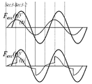
- FIG. 6 to 8 are views illustrating active phase control according to an embodiment of the present invention.
- FIG. 9 is a diagram illustrating an active phase control method for maximum output tracking according to an exemplary embodiment of the present invention.
- FIG. 1 is a view schematically showing the appearance of a wave power generation system according to an embodiment of the present invention.
- the wave power generation system 100 of the present invention may include a buoy 110, a chamber 125, a linear generator 120, and a power converter 140. Additionally, the wave power generation system 100 may further include a power system that receives the maximum output following power by the power converter 140.
- Buoy 110 is a floating body to reduce the resistance received from the sea surface (that is, above the sea), it is provided in a shape that can ride the wave 10 well on the sea surface.
- the shape of the buoy 110 may be provided in various shapes such as sphere, hemisphere, disc, cylinder, rod, cone, and the like.
- the buoy of the rectangular shape is illustrated, but the present invention is not limited thereto.
- the buoy 110 may include a buoyant body of a light, buoyant, very strong and non-corrosive material such as polystyrene foam or polyethylene foam resin. Radiation attenuation of the float by buoy 110 may be applied in the equation of motion related to the thrust of the wave power generation system 100, where the radiation attenuation of the floating float may be specified according to the characteristics of buoy 110. .
- the chamber 125 has a linear generator 120 installed therein, and at least a portion of the buoy 110 connected to a portion of the linear generator 120 or a shaft to which the buoy 110 is connected may be moved up and down. Can provide space. Chamber 125 may be provided in a cylindrical shape to minimize the effects of algae. It may include elastic members disposed on the upper wall and the lower wall inside the chamber 125. Alternatively, the elastic member may be disposed on a portion of the sidewall of the chamber 125 to perform a damper function to minimize the damage caused by the collision with the chamber 125 in the vertical movement of the linear generator in the chamber 125. By chamber 125, the wave power generation system can be subjected to fluid viscous damping.
- the chamber 125 may be fixed in various forms. For example, the chamber 125 may be located above a certain height above the sea level based on a support structure firmly fixed to the bottom of the sea floor. The support structure may comprise a concrete slab, for example.
- the linear generator 120 includes a stator 121, a shaft 123, and a mover 122.
- the stator 121 is fixedly installed in the chamber 125.
- the stator 121 may be provided in a cylindrical shape, and a hole may be provided in the center so that the mover 122 may be moved up and down.
- the inner wall of the central hole of the stator 121 may have a plurality of slots in which coils are wound. The coil generates and generates induced electromotive force through the relative movement of permanent magnets disposed in the mover 122.
- An insulating layer may be further disposed between the coil and the mover 122.
- the shaft 123 receives the kinetic energy from the buoy 110 and is installed to be movable up and down in the chamber 125.
- the shaft 123 has an elliptical or polygonal cross section.
- the cross section of the shaft may be provided at three, five, six or more angles.
- the mover 122 is installed on each surface constituting the polygonal structure in the shaft 123 having the cross-section of the polygonal structure.
- the mover 122 may include permanent magnets respectively installed on four surfaces.
- the mover 122 has a slot formed in the vertical direction so that the coil 312 of the stator 121 is accommodated, and permanent magnets may be disposed based on the slot.
- the power converter 140 calculates and estimates the speed of the wave based on the position change information of the wave power generation system 100 (for example, the position change of the buoy 110, the shaft 123, and the mover 122). Active phase control can be performed based on the speed of the waves. In this operation, the power converter 140 may perform optimal damping control or maximum damping control according to the relationship between the speed period of the wave and the period of thrust.
- FIG. 2 is a view schematically showing a wave power generation system configuration according to an embodiment of the present invention.
- the wave power generation system 100 may include a buoy 110, a linear generator 120, a position sensor 130, and a power conversion device 140. Additionally, the wave power generation system 100 may further include a configuration such as the chamber 125 described above.
- the buoy 110 and the linear generator 120 may have a structure as described above in FIG. 1.
- the position sensor 130 may be disposed at one side of the mover 122 and collect position information when the position is changed in response to the movement of the buoy 110.
- the position sensor 130 may be disposed on one side of the buoy 110 or disposed on the shaft 123 to collect position information, and transmit the collected position information to the power conversion device 140.
- the power conversion device 140 may calculate the speed of the wave based on the location information provided by the position sensor 130.
- the power converter 140 may detect the speed period of the wave based on the change in the speed of the wave with respect to time.
- the wave power generation system 100 including the linear generator 120 described with reference to FIG. 1 may have a thrust according to a motion equation as shown in Equation 1 below.
- 3 to 5 is a view showing a change in the speed cycle of the thrust and waves acting on the wave power generation system according to an embodiment of the present invention.
- the acceleration in relation to the acceleration is parallel to the buoyancy vector A ⁇ g, but the direction of the vector is opposite, and the magnitude may correspond to some magnitude of the buoyancy vector A ⁇ g.
- the velocity term vector (-(B pto + B vis + B rad ) ⁇ ) with respect to velocity starts at the end of the buoyancy vector (A ⁇ g) and is parallel to the buoy velocity vector (Im), with the endpoint of the vector being the acceleration term vector. It can be an endpoint.
- the thrust vector F may have a vector value extending from the start point of the buoy velocity vector Im and the buoy position vector Re to the end point of the velocity term vector.
- the period of thrust corresponding to the arrangement of the vectors described above may be arranged after the velocity period of the wave in the time axis as shown.
- the buoyancy vector A ⁇ g is formed in parallel with the buoy position vector Re, and the acceleration term vector in relation to the acceleration is shown.
- (-(M + m) ⁇ 2 ) is parallel to the buoyancy vector A ⁇ g, but the direction of the vector is opposite, and the magnitude may correspond to the same magnitude as the buoyancy vector A ⁇ g.
- the velocity term vector (-(B pto + B vis + B rad ) ⁇ ) related to velocity is parallel to the buoy velocity vector Im but may have a larger value than the buoy velocity vector Im.
- the thrust vector F may have the same value as the buoy velocity vector Im.
- the period of thrust corresponding to the arrangement of the vectors described above may have the same period as the velocity period of the wave in the time axis as shown.
- the buoy position vector Re is formed below and the buoy velocity vector Im is formed at right angles to the buoy position vector Re, so that the buoyancy vector A ⁇ g is the buoy position vector Re. It is formed parallel to the size may have a predetermined size of the buoyancy vector (A pg).
- the thrust vector F may have a vector value from the start point of the buoy velocity vector Im and the buoy position vector Re to the end point of the velocity term vector (-(B pto + B vis + B rad ) ⁇ ). have.
- the period of thrust corresponding to the arrangement of the vectors described above may be arranged before the velocity period of the wave in the time axis as shown.
- the power output by the wave power generation system 100 can be expressed by the product of the thrust and the speed, as shown in the following equation (5).
- Equation 5 higher power can be expected as the speed periodic phase of the wave coincides with the periodic phase of the thrust.
- P may correspond to power
- v may correspond to the speed of the wave.
- the wave power generation system 100 may perform power generation control in three manners as shown in FIGS. 6 to 8.
- 6 to 8 are diagrams illustrating control according to a phase according to an exemplary embodiment of the present invention.
- the power converter 140 may determine a control section according to a phase every 1/4 period of the speed.
- FIG. 6 illustrates a case in which the period of the wave is greater than the resonance period, and the power converter 140 applies an optimal damping value in the first quarter so that the period of the wave velocity matches the period of the thrust. At / 4 cycles, the maximum damping value is used to reduce buoy behavior.
- the power converter 140 may process to apply optimal damping in all sections.
- the power converter 140 reduces the buoy behavior by applying the maximum damping value in the first quarter period and matches the phase of the overall wave speed and thrust by using the optimum damping value in the second quarter period. Can be processed.
- FIG. 9 is a diagram illustrating an active phase control method according to an embodiment of the present invention.
- the power conversion device 140 of the wave power generation system 100 may collect position change information in step 501. Can be.
- the power conversion device 140 is a real-time location information from the position sensor disposed in at least one configuration (for example, buoy, shaft, mover, etc.) position changes by the wave of the wave power generation system 100 Can be received at regular intervals.
- the power converter 140 may detect a change in speed of the wave based on the received position information. For example, the power converter 140 may detect a speed change value that gradually decreases or gradually increases in response to a wave generated in a wave shape having a predetermined size. The power conversion device 140 may calculate the wave velocity period based on the detected wave velocity.
- the power converter 140 may analyze the relationship between the resonance period of the thrust and the period of the wave. For example, the power converter 140 may detect the thrust based on the equation of motion applied to the wave power generation system 100 described with reference to FIG. 1. The detected thrust may be detected in a form having a constant frequency value on the time axis. The power converter 140 may compare the calculated resonant period of thrust with the period of the wave speed and compare whether the same or which period is large.
- the power conversion device 140 may perform power generation control by performing optimal damping or maximum damping control according to the relationship. For example, in the region where the wave velocity period and the resonant period of thrust do not coincide, the power converter 140 reduces the buoy behavior by performing the maximum damping control according to the state, or performs the damping period by performing the optimal damping control.
- the operation of matching the resonance period of thrust and thrust may be performed.
- the power converter 140 may perform optimal damping control in a section in which the resonance period increases in response to the rising wave speed period to perform maximum output tracking according to phase matching.
- the power converter 140 may control the wave power generation system 100 to minimize the behavior of the buoy in a section in which the resonant period falls during the rising of the wave speed period or the wave speed period falls during the rising of the resonant period.
- the power converter 140 has a full cycle when the wave velocity period and the resonant period continue to coincide (for example, when the resonant period rises while the wave speed period rises and the resonant period falls while the wave speed period falls). Optimal damping control can be performed for.
Landscapes
- Engineering & Computer Science (AREA)
- Power Engineering (AREA)
- Chemical & Material Sciences (AREA)
- Combustion & Propulsion (AREA)
- Mechanical Engineering (AREA)
- General Engineering & Computer Science (AREA)
- Life Sciences & Earth Sciences (AREA)
- Sustainable Development (AREA)
- Sustainable Energy (AREA)
- Physics & Mathematics (AREA)
- Electromagnetism (AREA)
- General Physics & Mathematics (AREA)
- Radar, Positioning & Navigation (AREA)
- Automation & Control Theory (AREA)
- Other Liquid Machine Or Engine Such As Wave Power Use (AREA)
Abstract
본 발명은 최대 출력 추종을 위한 능동 위상 제어 방법 및 이를 지원하는 파력 발전 시스템에 관한 것이다. 본 발명은 부이에 연결된 선형 발전기, 선형 발전기의 발전 제어를 수행하는 전력 변환 장치를 포함하고, 전력 변환 장치는 파도의 주기와 선형 발전기의 추력의 공진 주기 사이의 차이를 분석하고, 분석 결과에 따라 최적 댐핑 제어 또는 최대 댐핑 제어 중 적어도 하나를 파도의 주기 중 적어도 일부에 적용하도록 설정된 파력 발전 시스템을 개시한다.
Description
본 발명은 파력 발전과 관련한 최대 출력 추정에 관한 것으로, 더욱 상세하게는 능동 위상 제어를 기반으로 최대 출력 추종을 수행할 수 있도록 하는 최대 출력 추종을 위한 능동 위상 제어 방법 및 이를 지원하는 파력 발전 시스템에 관한 것이다.
산업발전 과정에서 화석 연료의 지나친 의존으로 인하여 온실가스 발생 등의 환경문제 및 에너지자원 부족의 문제가 발생하고 있다. 이에 따라, 최근에는 친환경적이며 무한 에너지원 형태의 신재생 에너지 개발에 관심이 집중되고 있다. 일 예로서 파랑에너지를 이용하는 파력 발전 설비가 주목받고 있다.
파력 발전 설비는 파랑의 위치에너지를 전기에너지로 변환하는 방식이다. 파력 발전 설비는 태양에너지나 풍력에너지 등 다른 에너지원에 비해 에너지원의 운용이 어느 정도 예측가능하고, 높은 전력밀도를 가지며, 설치 장소에 제약이 적다는 장점이 있다. 이에 따라, 최근 파력 발전 설비와 관련하여 다양한 구조의 변형 및 실용화가 시도되고 있는 실정이다.
그러나 종래 파력 발전 설비의 경우, 파도의 불규칙한 크기 및 주기와 상관없이 일정 댐핑을 이용한 발전을 하고 있어서 발전량이 상대적으로 적은 문제가 있었다.
[선행기술문헌]
[특허문헌]
한국공개특허 제2010-0119741호(2010.11.10.)
본 발명은 상기와 같은 문제 해결을 위해 제안된 것으로, 파도의 속도와 추력의 위상차를 줄임으로써, 최대 출력을 추종하여 상대적으로 높고 안정적인 전력 공급을 달성할 수 있는 최대 출력 추종을 위한 능동 위상 제어 방법 및 이를 지원하는 파력 발전 시스템을 제공함에 있다.
상술한 목적을 달성하기 위하여, 본 발명의 파력 발전 시스템은 부이에 연결된 선형 발전기, 상기 선형 발전기의 발전 제어를 수행하는 전력 변환 장치를 포함하고, 상기 전력 변환 장치는 파도의 주기와 상기 선형 발전기의 추력의 공진 주기 사이의 차이를 분석하고, 분석 결과에 따라 최적 댐핑 제어 또는 최대 댐핑 제어 중 적어도 하나를 상기 파도의 주기 중 적어도 일부에 적용하도록 설정된 것을 특징으로 한다.
상기 전력 변환 장치는 파도의 주기가 상기 공진 주기보다 앞서는 경우, 4개의 부분 주기로 구분된 파도의 주기 중 상기 공진 주기보다 앞선 일부 1/4주기에서는 최대 댐핑 제어를 수행하고, 이후 일부 2/4주기에서는 최적 댐핑 제어를 수행하도록 설정된 것을 특징으로 한다.
상기 전력 변환 장치는 상기 파도의 주기와 상기 공진 주기가 일치하는 경우 전 구간에서 최적 댐핑 제어를 수행하도록 설정된 것을 특징으로 한다.
상기 전력 변환 장치는 상기 파도의 주기가 상기 공진 주기보다 뒤처지는 경우, 4개의 부분 주기로 구분된 파도의 주기 중 상기 공진 주기보다 뒤처진 일부 1/4주기에서는 최적 댐핑 제어를 수행하고, 이후 일부 2/4주기에서는 최대 댐핑 제어를 수행하도록 설정된 것을 특징으로 한다.
본 발명의 최대 출력 추종을 위한 능동 위상 제어 방법은 부이가 연결된 선형 발전기에서의 유동체의 움직임과 관련한 위치 정보를 수집하는 단계, 상기 위치 정보를 기반으로 파도의 속도 주기를 산출하는 단계, 상기 선형 발전기와 관련한 추력의 공진 주기와 상기 파도의 속도 주기 간의 위상 차를 분석하고, 분석 결과에 따라 상기 파도의 주기 중 적어도 일부 주기 동안 최대 댐핑 제어 및 최적 댐핑 제어 중 적어도 하나를 적용하여 발전하는 단계를 포함하는 것을 특징으로 한다.
상기 발전하는 단계는 파도의 주기가 상기 공진 주기보다 앞서는 경우, 4개의 부분 주기로 구분된 파도의 주기 중 상기 공진 주기보다 앞선 일부 1/4주기에서는 최대 댐핑 제어를 수행하고, 이후 일부 2/4주기에서는 최적 댐핑 제어를 수행하는 단계, 상기 파도의 주기와 상기 공진 주기가 일치하는 경우 전 구간에서 최적 댐핑 제어를 수행하는 단계, 상기 파도의 주기가 상기 공진 주기보다 뒤처지는 경우, 4개의 부분 주기로 구분된 파도의 주기 중 상기 공진 주기보다 뒤처진 일부 1/4주기에서는 최적 댐핑 제어를 수행하고, 이후 일부 2/4주기에서는 최대 댐핑 제어를 수행하는 단계를 포함하는 것을 특징으로 한다.
이상에서 살펴본 바와 같이 본 발명에서 제시하는 최대 출력 추종을 위한 능동 위상 제어 방법 및 이를 지원하는 파력 발전 시스템에 따르면, 본 발명은 파도 속도와 추력의 위상 차를 줄임으로써 안정적이며 높은 출력 파워를 제공할 수 있다.
도 1은 본 발명의 실시 예에 따른 파력 발전 시스템 외관을 개략적으로 나타낸 도면,
도 2는 본 발명의 실시 예에 따른 파력 발전 시스템 구성을 개략적으로 나타낸 도면,
도 3 내지 도 5는 파도의 주기와 추력과의 관계를 나타낸 도면,
도 6 내지 도 8은 본 발명의 실시 예에 따른 능동 위상 제어를 설명하는 도면,
도 9는 본 발명의 실시 예에 따른 최대 출력 추종을 위한 능동 위상 제어 방법을 설명하는 도면이다.
이하, 첨부 도면을 참조하여 본 발명의 실시 예를 보다 상세하게 설명하고자 한다. 하기의 설명에서는 본 발명의 실시 예를 이해하는데 필요한 부분만이 설명되며, 그 이외 부분의 설명은 본 발명의 요지를 흩트리지 않도록 생략될 것이라는 것을 유의하여야 한다.
이하에서 설명되는 본 명세서 및 청구범위에 사용된 용어나 단어는 통상적이거나 사전적인 의미로 한정해서 해석되어서는 아니 되며, 발명자는 그 자신의 발명을 가장 최선의 방법으로 설명하기 위해 용어의 개념으로 적절하게 정의할 수 있다는 원칙에 입각하여 본 발명의 기술적 사상에 부합하는 의미와 개념으로 해석되어야만 한다. 따라서 본 명세서에 기재된 실시 예와 도면에 도시된 구성은 본 발명의 바람직한 실시 예에 불과할 뿐이고, 본 발명의 기술적 사상을 모두 대변하는 것은 아니므로, 본 발명의 출원시점에 있어서 이들을 대체할 수 있는 다양한 균등물과 변형 예들이 있을 수 있음을 이해하여야 한다.
이하, 상기한 목적을 달성하기 위한 본 발명의 바람직한 실시 예를 첨부된 도면을 참조하여 상세히 설명하면 다음과 같다.
도 1은 본 발명의 실시 예에 따른 파력 발전 시스템 외관을 개략적으로 나타낸 도면이다.
도 1을 참조하면, 본 발명의 파력 발전 시스템(100)은 부이(110), 챔버(125), 선형 발전기(120), 전력 변환 장치(140)를 포함할 수 있다. 추가적으로, 파력 발전 시스템(100)은 전력 변환 장치(140)에 의하여 최대 출력 추종된 전력을 전달받는 전력 계통을 더 포함할 수 있다.
부이(110)는 부유체로서 해수면(즉, 바다 위)에서 받는 저항을 줄여주고, 해수면에서 파도(10)를 잘 탈 수 있는 형상으로 제공된다. 일 예로, 부이(110)의 형상 중 적어도 일부는 구, 반구, 원반, 원기둥, 봉, 원뿔 등의 다양한 형상으로 제공될 수 있다. 본 발명의 실시 예에서는 사각형 형상의 부이를 도시하였으나, 본 발명이 이에 한정되는 것은 아니다. 부이(110)는 폴리스티렌 폼(Polystyrene foam) 또는 폴리에틸렌 발포수지 재질과 같은 가볍고, 부력이 매우 강하며 부식성이 없는 소재의 부력체를 포함할 수 있다. 파력 발전 시스템(100)의 추력과 관련한 운동 방정식에서 부이(110)에 의한 부유체의 방사 감쇠가 적용될 수 있는데, 이때, 상가 부유체의 방사 감쇠는 부이(110)의 특성에 따라 특정될 수 있다.
챔버(125)는 내부에 선형 발전기(120)가 설치되고, 선형 발전기(120)의 일부와 연결되는 부이(110)의 적어도 일부가 또는 부이(110)가 연결되는 샤프트가 상하 이동될 수 있는 내부 공간을 제공할 수 있다. 챔버(125)는 조류의 영향을 최소화하기 위해 원통형상으로 제공될 수 있다. 챔버(125) 내부의 상부벽과 하부벽에 배치되는 탄성 부재들을 포함할 수 있다. 또는, 탄성 부재는 챔버(125) 내부의 측벽 일부에 배치되어 챔버(125) 내부에서 선형 발전기의 상하 운동 과정에서 챔버(125)와의 충돌로 인한 데미지를 최소화하기 위한 댐퍼 기능을 수행할 수 있다. 챔버(125)에 의해 파력 발전 시스템은 유체 점성 감쇠가 적용될 수 있다. 챔버(125)는 다양한 형태로 고정될 수 있다. 예컨대, 챔버(125)는 해저 바닥에 단단하게 고정된 지지 구조를 기반으로 해수면 보다 일정 높이 이상에 위치할 수 있다. 지지 구조는 예컨대, 콘크리트 슬라브를 포함할 수 있다.
선형 발전기(120)는 고정자(121), 샤프트(123), 그리고 가동자(122)를 포함한다.
고정자(121)는 챔버(125)의 내부에 고정 설치된다. 본 발명의 실시 예에서 고정자(121)는 원통형으로 마련되고, 중앙에 가동자(122)가 상하로 이동될 수 있도록 홀이 마련될 수 있다. 고정자(121)의 중앙 홀 내벽은 코일이 감겨진 복수개의 슬롯들이 배치될 수 있다. 코일은 가동자(122)에 배치되는 영구자석들의 상대적 이동을 통해 유도 기전력이 발생되어 발전한다. 코일과 가동자(122) 사이에 절연층이 더 배치될 수 있다.
샤프트(123)는 부이(110)로부터 운동 에너지를 제공받아 챔버(125) 내에서 상하 방향으로 이동 가능하게 설치된다. 샤프트(123)는 타원 또는 다각 구조의 단면을 갖는다. 샤프트의 단면은 3각, 5각, 6각 그 이상으로 제공될 수 있다.
가동자(122)는 다각 구조의 단면을 갖는 샤프트(123)에서 다각 구조를 구성하는 각 면에 설치된다. 예컨대, 샤프트(123)가 4각 단면을 가지는 경우, 가동자(122)는 4개의 면에 각각 설치된 영구자석들을 포함할 수 있다. 가동자(122)는 고정자(121)의 코일(312)이 수용되도록 상하 방향으로 슬롯이 형성되고, 슬롯을 기준으로 영구자석들이 배치될 수 있다.
전력 변환 장치(140)는 파력 발전 시스템(100)의 위치 변화 정보(예: 부이(110), 샤프트(123), 가동자(122)의 위치 변화)를 기반으로 파도의 속도를 산출하고, 추정된 파도의 속도를 기반으로 능동 위상 제어를 수행할 수 있다. 이 동작에서, 전력 변환 장치(140)는 파도의 속도 주기와 추력의 주기와의 관계에 따라, 최적 댐핑 제어를 수행하거나 또는 최대 댐핑 제어를 수행할 수 있다.
도 2는 본 발명의 실시 예에 따른 파력 발전 시스템 구성을 개략적으로 나타낸 도면이다.
도 2를 참조하면, 본 발명의 실시 예에 따른 파력 발전 시스템(100)은 부이(110), 선형 발전기(120), 위치 센서(130), 전력 변환 장치(140)를 포함할 수 있다. 추가적으로 파력 발전 시스템(100)은 상술한 챔버(125) 등의 구성을 더 포함할 수 있다.
부이(110) 및 선형 발전기(120)는 앞서 도 1에서 설명한 바와 같은 구조를 가지를 가질 수 있다. 위치 센서(130)는 예컨대, 가동자(122)의 일측에 배치되어 부이(110)의 이동에 대응하여 위치가 변경될 경우, 위치 정보를 수집할 수 있다. 또는, 위치 센서(130)는 부이(110) 일측에 배치되거나 샤프트(123)에 배치되어 위치 정보를 수집하고, 수집된 위치 정보를 전력 변환 장치(140)에 전달할 수 있다.
전력 변환 장치(140)는 위치 센서(130)가 제공한 위치 정보를 기반으로 파도의 속도를 산출할 수 있다. 전력 변환 장치(140)는 시간에 대한 파도의 속도 변화를 기반으로 파도의 속도 주기를 검출할 수 있다. 한편, 도 1에서 설명한 선형 발전기(120)를 포함하는 파력 발전 시스템(100)은 다음 수학식 1과 같은 운동 방정식에 따른 추력을 가질 수 있다.
[수학식 1]

여기서, M: 부이질량, m:추가질량, Brad: radiation damping, Bvis: viscous damping, Bpto: 발전기 damping (발전량), Aρgy(t):부력, y(t) : 위치, y'(t):속도, y"(t):가속도, Fext : excitation force을 의미할 수 있다. 위 운동 방정식을 기반으로 하는 파도의 주기에 따른 위상 변화는 도 3 내지 도 5와 같이 나타날 수 있다.
도 3 내지 도 5는 본 발명의 실시 예에 따른 파력 발전 시스템에 작용하는 추력과 파도의 속도 주기 변화를 나타낸 도면이다.
도 3을 참조하면, 파도의 속도 ω가 다음과 같은 수학식 2를 만족하고, 파도의 속도 주기가 출력의 공진 주기보다 앞서는 조건(period > 공진 주기)인 경우, 도시된 바와 같은 형태의 벡터들의 배치에 따라 추력(F)이 표현될 수 있다.
[수학식 2]

도시된 도면을 살펴보면, 부이 속도 벡터(Im)와 부이 위치 벡터(Re) 관계가 직각으로 형성된 상태에서, 부력 벡터(Aρg)가 부이 위치 벡터(Re)와 나란하게 형성되는 경우, 가속도와 관련한 가속도 항 벡터(-(M+m)ω2)는 부력 벡터(Aρg)와 나란하되 벡터의 방향이 반대이고, 크기는 부력 벡터(Aρg)의 일부 크기에 대응될 수 있다. 속도와 관련한 속도 항 벡터(-(Bpto+Bvis+Brad)ω) 값은 부력 벡터(Aρg)의 끝점에서 시작하여 부이 속도 벡터(Im)와 나란하되, 벡터의 끝점이 가속도 항 벡터의 끝점이 될 수 있다. 이에 따라, 추력 벡터(F)는 부이 속도 벡터(Im)와 부이 위치 벡터(Re)의 시작점에서부터 속도 항 벡터의 끝점까지 이어지는 벡터 값을 가질 수 있다. 상술한 벡터들의 배치에 대응하는 추력의 주기는 도시된 바와 같이 시간축에서 파도의 속도 주기보다 뒤에 배치될 수 있다.
도 4를 참조하면, 파도의 속도 ω가 다음과 같은 수학식 3을 만족하고, 파도의 속도 주기가 출력의 공진 주기와 일치되는 조건(period = 공진 주기)인 경우, 도시된 바와 같은 형태의 벡터들의 형성에 따라 추력(F)이 표현될 수 있다.
[수학식 3]

도시된 도면을 살펴보면, 부이 속도 벡터(Im)와 부이 위치 벡터(Re) 관계가 직각인 상태에서, 부력 벡터(Aρg)가 부이 위치 벡터(Re)와 나란하게 형성되고, 가속도와 관련한 가속도 항 벡터(-(M+m)ω2)는 부력 벡터(Aρg)와 나란하되 벡터의 방향이 반대이며, 크기는 부력 벡터(Aρg)와 동일한 크기에 대응될 수 있다. 속도와 관련한 속도 항 벡터(-(Bpto+Bvis+Brad)ω) 값은 부이 속도 벡터(Im)와 나란하되, 부이 속도 벡터(Im)보다 큰 값을 가질 수 있다. 추력 벡터(F)는 부이 속도 벡터(Im)와 동일한 값을 가질 수 있다. 상술한 벡터들의 배치에 대응하는 추력의 주기는 도시된 바와 같이 시간축에서 파도의 속도 주기와 동일한 주기를 가질 수 있다.
도 5를 참조하면, 파도의 속도 ω가 다음과 같은 수학식 4를 만족하고, 파도의 속도 주기가 출력의 공진 주기보다 뒤처지는 조건(period < 공진 주기)인 경우, 도시된 바와 같은 형태의 벡터들의 형성에 따라 추력(F)이 표현될 수 있다.
[수학식 4]

도시된 도면을 살펴보면, 부이 위치 벡터(Re)가 직하방으로 형성되고, 부이 속도 벡터(Im)가 부이 위치 벡터(Re)와 직각으로 형성된 상태에서, 부력 벡터(Aρg)는 부이 위치 벡터(Re)와 나란하게 형성되데 크기는 부력 벡터(Aρg)의 일정 크기를 가질 수 있다. 가속도와 관련한 가속도 항 벡터(-(M+m)ω2)는 부력 벡터(Aρg)의 끝점에서 부력 벡터(Aρg)와 반대 방향으로 형성되고, 속도와 관련한 속도 항 벡터(-(Bpto+Bvis+Brad)ω) 값은 부력 벡터(Aρg)의 끝점에서 시작하여 부이 속도 벡터(Im)와 방향 및 크기가 유사하게 형성될 수 있다. 여기서, 추력 벡터(F)는 부이 속도 벡터(Im)와 부이 위치 벡터(Re)의 시작점에서부터 속도 항 벡터(-(Bpto+Bvis+Brad)ω)의 끝점까지 이어지는 벡터 값을 가질 수 있다. 상술한 벡터들의 배치에 대응하는 추력의 주기는 도시된 바와 같이 시간축에서 파도의 속도 주기보다 앞에 배치될 수 있다.
한편, 파력 발전 시스템(100)에 의하여 출력되는 파워는 다음 수학식 5와 같이, 추력과 속도의 곱으로 표현될 수 있다.
[수학식 5]
P=Fv
수학식 5에 따르면, 파도의 속도 주기 위상과 추력의 주기 위상이 일치할수록 높은 파워를 기대할 수 있다. 여기서, 여기서 P는 전력, F는 출력, v는 파도의 속도에 대응할 수 있다.
도 3 내지 5에서 설명한 바와 같이, 파도의 주기가 공진주기보다 클 경우 파도 속도의 위상이 공진 주기보다 앞서게 되며, 작을 경우 파도 속도의 위상이 공진 주기보다 뒤처지게 된다. 파도의 속도와 추력의 위상을 보정하기 위하여 파력 발전 시스템(100)은 도 6 내지 도 8에서와 같이 3개의 방식으로 구분하여 발전 제어를 수행할 수 있다.
도 6 내지 도 8은 본 발명의 실시 예에 따른 위상에 따른 제어를 설명하는 도면이다.
도 6을 참조하면, 전력 변환 장치(140)는 위상에 따른 제어 구간을 속도의 1/4주기마다 결정되도록 할 수 있다. 도 6은 파도의 주기가 공진주기보다 큰 경우 이며, 전력 변환 장치(140)는 처음 1/4주기에서는 최적댐핑값을 적용하여 파도 속도의 주기와 추력의 주기를 일치시키도록 하고, 두 번째 1/4주기에서는 최대댐핑값을 이용하여 부이의 거동을 줄이도록 한다.
도 7은 파도주기와 공진주기가 일치하는 경우를 나타낸 것이다. 이 경우에서, 전력 변환 장치(140)는 모든 구간에서 최적댐핑을 적용하도록 처리할 수 있다.
도 8은 파도의 주기가 공진주기보다 작은 경우이다. 전력 변환 장치(140)는 처음 1/4주기에서는 최대댐핑값을 적용하여 부이의 거동을 줄이고, 두 번째 1/4주기에서는 최적댐핑값을 이용하여 전체적인 파도의 속도와 추력의 위상을 일치시키도록 처리할 수 있다.
도 9는 본 발명의 실시 예에 따른 능동 위상 제어 방법을 나타낸 도면이다.
도 9를 참조하면, 최대 출력 추종을 위한 능동 위상 제어 방법과 관련하여, 파력 발전 시스템(100)의 전력 변환 장치(140)는 501 단계에서, 전력 변환 장치(140)는 위치 변화 정보를 수집할 수 있다. 이와 관련하여, 전력 변환 장치(140)는 파력 발전 시스템(100) 중 파도에 의하여 위치가 변화되는 구성(예: 부이, 샤프트, 가동자 등)에 적어도 하나에 배치된 위치 센서로부터 위치 정보를 실시간으로 또는 일정 주기로 수신할 수 있다.
503 단계에서, 전력 변환 장치(140)는 수신된 위치 정보를 기반으로 파도의 속도 변화를 검출할 수 있다. 예컨대, 전력 변환 장치(140)는 일정 크기의 웨이브 형태로 발생하는 파도에 대응하여 점진적으로 감소하거나 또는 점진적으로 증가하는 속도 변화 값을 검출할 수 있다. 전력 변환 장치(140)는 검출된 파도이 속도 변화를 기반으로 파도 속도 주기를 산출할 수 있다.
505 단계에서, 전력 변환 장치(140)는 추력의 공진 주기와 파도의 주기 간의 관계 분석을 수행할 수 있다. 예컨대, 전력 변환 장치(140)는 도 1 등에서 설명한 파력 발전 시스템(100)에 적용된 운동 방정식을 기반으로, 추력을 검출할 수 있다. 검출된 추력은 시간축에서 일정 주파수 값을 가지는 형태로 검출될 수 있다. 전력 변환 장치(140)는 산출된 추력의 공진 주기와 파도 속도의 주기를 비교하여 동일한지 또는 어떠한 주기가 큰지를 비교할 수 있다.
507 단계에서, 전력 변환 장치(140)는 관계에 따라, 최적 댐핑 또는 최대 댐핑 제어 수행하여 발전 제어를 수행할 수 있다. 예컨대, 전력 변환 장치(140)는 파도 속도 주기와 추력의 공진 주기가 일치하지 않는 구역에서는 상태에 따라 최대 댐핑 제어를 수행하여 부이의 거동을 줄이거나, 또는 최적 댐핑 제어를 수행하여 파도 속도의 주기와 추력의 공진 주기를 일치시키는 작업을 수행할 수 있다. 예컨대, 전력 변환 장치(140)는 파도 속도 주기 상승에 대응하여 공진 주기가 상승하는 구간에서는 최적 댐핑 제어를 수행하여 위상 일치에 따라 최대 출력 추종을 수행할 수 있다. 전력 변환 장치(140)는 파도 속도 주기 상승 중에 공진 주기가 하강하거나 또는 공진 주기 상승 중에 파도 속도 주기가 하강하는 구간에서는 부이의 거동을 최소화하도록 파력 발전 시스템(100)을 제어할 수 있다. 전력 변환 장치(140)는 파도 속도 주기와 공진 주기가 계속 일치하는 경우(예: 파도 속도 주기가 상승하는 중에 공진 주기가 상승하고, 파도 속도 주기가 하강하는 동안 공진 주기가 하강하는 경우) 전 주기에 대하여 최적 댐핑 제어를 수행할 수 있다.
한편, 본 명세서와 도면에 개시된 본 발명의 실시 예들은 이해를 돕기 위해 특정 예를 제시한 것에 지나지 않으며, 본 발명의 범위를 한정하고자 하는 것은 아니다. 여기에 개시된 실시 예들 이외에도 본 발명의 기술적 사상에 바탕을 둔 다른 변형 예들이 실시 가능하다는 것은, 본 발명이 속하는 기술분야에서 통상의 지식을 가진 자에게 자명한 것이다.
[부호의 설명]
100 : 파력 발전 시스템
110 : 부이
120 : 선형 발전기
121 : 고정자
122 : 가동자
123 : 샤프트
125 : 챔버
130 : 위치 센서
140 : 전력 변환 장치
Claims (6)
- 부이에 연결된 선형 발전기;상기 선형 발전기의 발전 제어를 수행하는 전력 변환 장치;를 포함하고,상기 전력 변환 장치는파도의 주기와 상기 선형 발전기의 추력의 공진 주기 사이의 차이를 분석하고, 분석 결과에 따라 최적 댐핑 제어 또는 최대 댐핑 제어 중 적어도 하나를 상기 파도의 주기 중 적어도 일부에 적용하도록 설정된 것을 특징으로 하는 파력 발전 시스템.
- 제1항에 있어서,상기 전력 변환 장치는파도의 주기가 상기 공진 주기보다 앞서는 경우, 4개의 부분 주기로 구분된 파도의 주기 중 상기 공진 주기보다 앞선 일부 1/4주기에서는 최대 댐핑 제어를 수행하고, 이후 일부 2/4주기에서는 최적 댐핑 제어를 수행하도록 설정된 것을 특징으로 하는 파력 발전 시스템.
- 제1항에 있어서,상기 전력 변환 장치는상기 파도의 주기와 상기 공진 주기가 일치하는 경우 전 구간에서 최적 댐핑 제어를 수행하도록 설정된 것을 특징으로 하는 파력 발전 시스템.
- 제1항에 있어서,상기 전력 변환 장치는상기 파도의 주기가 상기 공진 주기보다 뒤처지는 경우, 4개의 부분 주기로 구분된 파도의 주기 중 상기 공진 주기보다 뒤처진 일부 1/4주기에서는 최적 댐핑 제어를 수행하고, 이후 일부 2/4주기에서는 최대 댐핑 제어를 수행하도록 설정된 것을 특징으로 하는 파력 발전 시스템.
- 부이가 연결된 선형 발전기에서의 유동체의 움직임과 관련한 위치 정보를 수집하는 단계;상기 위치 정보를 기반으로 파도의 속도 주기를 산출하는 단계;상기 선형 발전기와 관련한 추력의 공진 주기와 상기 파도의 속도 주기 간의 위상 차를 분석하고, 분석 결과에 따라 상기 파도의 주기 중 적어도 일부 주기 동안 최대 댐핑 제어 및 최적 댐핑 제어 중 적어도 하나를 적용하여 발전하는 단계;를 포함하는 것을 특징으로 하는 최대 출력 추종을 위한 능동 위상 제어 방법.
- 제5항에 있어서,상기 발전하는 단계는파도의 주기가 상기 공진 주기보다 앞서는 경우, 4개의 부분 주기로 구분된 파도의 주기 중 상기 공진 주기보다 앞선 일부 1/4주기에서는 최대 댐핑 제어를 수행하고, 이후 일부 2/4주기에서는 최적 댐핑 제어를 수행하는 단계;상기 파도의 주기와 상기 공진 주기가 일치하는 경우 전 구간에서 최적 댐핑 제어를 수행하는 단계;상기 파도의 주기가 상기 공진 주기보다 뒤처지는 경우, 4개의 부분 주기로 구분된 파도의 주기 중 상기 공진 주기보다 뒤처진 일부 1/4주기에서는 최적 댐핑 제어를 수행하고, 이후 일부 2/4주기에서는 최대 댐핑 제어를 수행하는 단계;를 포함하는 것을 특징으로 하는 최대 출력 추종을 위한 능동 위상 제어 방법.
Applications Claiming Priority (2)
| Application Number | Priority Date | Filing Date | Title |
|---|---|---|---|
| KR1020160034746A KR101850714B1 (ko) | 2016-03-23 | 2016-03-23 | 최대 출력 추종을 위한 능동 위상 제어 방법 및 이를 지원하는 파력 발전 시스템 |
| KR10-2016-0034746 | 2016-03-23 |
Publications (1)
| Publication Number | Publication Date |
|---|---|
| WO2017164450A1 true WO2017164450A1 (ko) | 2017-09-28 |
Family
ID=59899618
Family Applications (1)
| Application Number | Title | Priority Date | Filing Date |
|---|---|---|---|
| PCT/KR2016/003172 Ceased WO2017164450A1 (ko) | 2016-03-23 | 2016-03-29 | 최대 출력 추종을 위한 능동 위상 제어 방법 및 이를 지원하는 파력 발전 시스템 |
Country Status (2)
| Country | Link |
|---|---|
| KR (1) | KR101850714B1 (ko) |
| WO (1) | WO2017164450A1 (ko) |
Cited By (3)
| Publication number | Priority date | Publication date | Assignee | Title |
|---|---|---|---|---|
| CN107766926A (zh) * | 2017-10-23 | 2018-03-06 | 广东工业大学 | 一种波浪发电的方法和系统 |
| CN114992034A (zh) * | 2022-06-21 | 2022-09-02 | 中国电建集团华东勘测设计研究院有限公司 | 基于多时间尺度综合查询的波浪能最大功率点跟踪方法 |
| CN118640126A (zh) * | 2024-05-31 | 2024-09-13 | 清华大学 | 一种全封闭振荡浮体装置及其控制方法、波浪发电系统 |
Families Citing this family (1)
| Publication number | Priority date | Publication date | Assignee | Title |
|---|---|---|---|---|
| KR102524191B1 (ko) * | 2021-09-30 | 2023-04-26 | (유)이원마린 | 부유체를 이용한 파력발전장치 |
Citations (5)
| Publication number | Priority date | Publication date | Assignee | Title |
|---|---|---|---|---|
| KR20120010101A (ko) * | 2010-07-21 | 2012-02-02 | 삼성중공업 주식회사 | 파력발전장치 |
| JP2013181433A (ja) * | 2012-02-29 | 2013-09-12 | Mitsubishi Heavy Ind Ltd | 波力発電装置およびその制御方法 |
| KR101411630B1 (ko) * | 2013-01-30 | 2014-06-25 | 삼성중공업 주식회사 | 파력 발전용 부체 및 이를 포함하는 파력발전장치 |
| KR20150008284A (ko) * | 2013-07-12 | 2015-01-22 | 한국전력공사 | 가변수주 진동장치 및 이를 이용한 파력 발전 장치 |
| KR20150134943A (ko) * | 2014-05-23 | 2015-12-02 | 한국해양과학기술원 | 부유식 파력 발전장치 및 이를 갖는 복합 발전시스템 |
-
2016
- 2016-03-23 KR KR1020160034746A patent/KR101850714B1/ko active Active
- 2016-03-29 WO PCT/KR2016/003172 patent/WO2017164450A1/ko not_active Ceased
Patent Citations (5)
| Publication number | Priority date | Publication date | Assignee | Title |
|---|---|---|---|---|
| KR20120010101A (ko) * | 2010-07-21 | 2012-02-02 | 삼성중공업 주식회사 | 파력발전장치 |
| JP2013181433A (ja) * | 2012-02-29 | 2013-09-12 | Mitsubishi Heavy Ind Ltd | 波力発電装置およびその制御方法 |
| KR101411630B1 (ko) * | 2013-01-30 | 2014-06-25 | 삼성중공업 주식회사 | 파력 발전용 부체 및 이를 포함하는 파력발전장치 |
| KR20150008284A (ko) * | 2013-07-12 | 2015-01-22 | 한국전력공사 | 가변수주 진동장치 및 이를 이용한 파력 발전 장치 |
| KR20150134943A (ko) * | 2014-05-23 | 2015-12-02 | 한국해양과학기술원 | 부유식 파력 발전장치 및 이를 갖는 복합 발전시스템 |
Cited By (3)
| Publication number | Priority date | Publication date | Assignee | Title |
|---|---|---|---|---|
| CN107766926A (zh) * | 2017-10-23 | 2018-03-06 | 广东工业大学 | 一种波浪发电的方法和系统 |
| CN114992034A (zh) * | 2022-06-21 | 2022-09-02 | 中国电建集团华东勘测设计研究院有限公司 | 基于多时间尺度综合查询的波浪能最大功率点跟踪方法 |
| CN118640126A (zh) * | 2024-05-31 | 2024-09-13 | 清华大学 | 一种全封闭振荡浮体装置及其控制方法、波浪发电系统 |
Also Published As
| Publication number | Publication date |
|---|---|
| KR20170110762A (ko) | 2017-10-12 |
| KR101850714B1 (ko) | 2018-04-23 |
Similar Documents
| Publication | Publication Date | Title |
|---|---|---|
| Lejerskog et al. | Experimental results on power absorption from a wave energy converter at the Lysekil wave energy research site | |
| WO2017164450A1 (ko) | 최대 출력 추종을 위한 능동 위상 제어 방법 및 이를 지원하는 파력 발전 시스템 | |
| Dai et al. | A wave energy harvesting system based on the double-wing flywheel for unmanned surface vessels | |
| Zhang et al. | Hybridized triboelectric-electromagnetic nanogenerators for efficient harvesting of wave energy for self-powered ocean buoy | |
| de Sousa Prado et al. | Modelling and test results of the Archimedes wave swing | |
| KR101640885B1 (ko) | 파랑 에너지를 이용한 시소 타입의 자가 발전 시스템 | |
| CN103733487B (zh) | 振动发电机 | |
| US20170321650A9 (en) | Wave power generation system and method | |
| CN114809765A (zh) | 液位可调节的调谐液柱阻尼器和塔筒 | |
| CN109296497A (zh) | 一种波浪能发电装置 | |
| Li et al. | A novel multi-degree of freedom kinetic energy harvester for self-powered low-power applications in ships | |
| KR101697099B1 (ko) | 최대출력 추종을 위한 최적 댐핑 제어 방법 및 이를 지원하는 파력 발전 시스템 | |
| Wang et al. | A New Active Motion Control Strategy for Built-in Wave Energy Converter of Ocean Data Buoys | |
| WO2012053769A2 (ko) | 파랑발전기 | |
| CN109698544A (zh) | 基于摩擦纳米发电机的风力发电集成系统 | |
| CN108678885B (zh) | 一种基于磁齿轮增速效应的波浪发电系统及其设计方法 | |
| CN110344994A (zh) | 一种双浮子波浪发电装置 | |
| KR20230123526A (ko) | 재생에너지 운송수단의 충전 및 보관시스템 | |
| CN220452089U (zh) | 一种基于涡流增强流致振动集群的系泊式发电系统 | |
| JPS6228316B2 (ko) | ||
| CN109139339A (zh) | 波浪能发电装置及发电方法 | |
| KR101697098B1 (ko) | 파도 주기 추정 방법 및 이를 지원하는 파력 발전기 | |
| WO2015012481A1 (ko) | 계류선의 공유를 통한 부유식 파력발전단지 구축방법 및 이를 이용한 부유식 파력발전 시스템 | |
| JP2014511974A (ja) | 運動をエネルギーに変換する装置および方法 | |
| CN104389724B (zh) | 一种波浪能量发电机 |
Legal Events
| Date | Code | Title | Description |
|---|---|---|---|
| NENP | Non-entry into the national phase |
Ref country code: DE |
|
| 121 | Ep: the epo has been informed by wipo that ep was designated in this application |
Ref document number: 16895578 Country of ref document: EP Kind code of ref document: A1 |
|
| 122 | Ep: pct application non-entry in european phase |
Ref document number: 16895578 Country of ref document: EP Kind code of ref document: A1 |