WO2017163463A1 - Cell sorting method and flow cytometry and cell sorter using same - Google Patents
Cell sorting method and flow cytometry and cell sorter using same Download PDFInfo
- Publication number
- WO2017163463A1 WO2017163463A1 PCT/JP2016/077645 JP2016077645W WO2017163463A1 WO 2017163463 A1 WO2017163463 A1 WO 2017163463A1 JP 2016077645 W JP2016077645 W JP 2016077645W WO 2017163463 A1 WO2017163463 A1 WO 2017163463A1
- Authority
- WO
- WIPO (PCT)
- Prior art keywords
- microwells
- gel
- cell
- microwell
- information
- Prior art date
Links
Images


Classifications
-
- C—CHEMISTRY; METALLURGY
- C12—BIOCHEMISTRY; BEER; SPIRITS; WINE; VINEGAR; MICROBIOLOGY; ENZYMOLOGY; MUTATION OR GENETIC ENGINEERING
- C12M—APPARATUS FOR ENZYMOLOGY OR MICROBIOLOGY; APPARATUS FOR CULTURING MICROORGANISMS FOR PRODUCING BIOMASS, FOR GROWING CELLS OR FOR OBTAINING FERMENTATION OR METABOLIC PRODUCTS, i.e. BIOREACTORS OR FERMENTERS
- C12M47/00—Means for after-treatment of the produced biomass or of the fermentation or metabolic products, e.g. storage of biomass
- C12M47/04—Cell isolation or sorting
-
- C—CHEMISTRY; METALLURGY
- C12—BIOCHEMISTRY; BEER; SPIRITS; WINE; VINEGAR; MICROBIOLOGY; ENZYMOLOGY; MUTATION OR GENETIC ENGINEERING
- C12N—MICROORGANISMS OR ENZYMES; COMPOSITIONS THEREOF; PROPAGATING, PRESERVING, OR MAINTAINING MICROORGANISMS; MUTATION OR GENETIC ENGINEERING; CULTURE MEDIA
- C12N1/00—Microorganisms, e.g. protozoa; Compositions thereof; Processes of propagating, maintaining or preserving microorganisms or compositions thereof; Processes of preparing or isolating a composition containing a microorganism; Culture media therefor
-
- G—PHYSICS
- G01—MEASURING; TESTING
- G01N—INVESTIGATING OR ANALYSING MATERIALS BY DETERMINING THEIR CHEMICAL OR PHYSICAL PROPERTIES
- G01N1/00—Sampling; Preparing specimens for investigation
- G01N1/02—Devices for withdrawing samples
- G01N1/04—Devices for withdrawing samples in the solid state, e.g. by cutting
-
- G—PHYSICS
- G01—MEASURING; TESTING
- G01N—INVESTIGATING OR ANALYSING MATERIALS BY DETERMINING THEIR CHEMICAL OR PHYSICAL PROPERTIES
- G01N15/00—Investigating characteristics of particles; Investigating permeability, pore-volume, or surface-area of porous materials
-
- G—PHYSICS
- G01—MEASURING; TESTING
- G01N—INVESTIGATING OR ANALYSING MATERIALS BY DETERMINING THEIR CHEMICAL OR PHYSICAL PROPERTIES
- G01N35/00—Automatic analysis not limited to methods or materials provided for in any single one of groups G01N1/00 - G01N33/00; Handling materials therefor
- G01N35/02—Automatic analysis not limited to methods or materials provided for in any single one of groups G01N1/00 - G01N33/00; Handling materials therefor using a plurality of sample containers moved by a conveyor system past one or more treatment or analysis stations
Definitions
- the present invention relates to a novel cell sorting method, and a flow cytometry and cell sorter using the same.
- Flow cytometry is a technique in which antibodies labeled with a fluorescent dye are bound to target cells, and particles are analyzed and separated by the fluorescence and scattered light.
- a technique for separating specific cells (including microorganisms) from a population of fine particles such as cells is a cell sorting technique (Non-patent Document 1).
- Cell sorting technology is a very important method for understanding cell behavior and cell function.
- Non-Patent Document 1 a suspension of target cells to which an antibody labeled with a fluorescent dye or the like is bound is used as a liquid flow.
- the desired cells are identified by analyzing the wavelength or intensity of the fluorescence or scattered light emitted from each cell.
- voltage is applied to the cells having specific properties identified by the analysis results such as the wavelength and intensity of the light, and the cells are charged by using a deflection electrode to discriminate, quantify and statistically analyze the charged cells.
- Cell engineering separate volume “Flow cytometry freedom”, supervised by: Hiromitsu Nakauchi (University of Tsukuba, Department of Medical Immunology), Shujunsha, issued July 1, 1999, pp. 3-23
- the conventional cell sorting technique is a technique for sequentially analyzing and recovering each cell flowing along a flow path. More specifically, the analysis is based on the absolute value of a signal (mainly fluorescence or scattered light) emitted from a cell at the moment of passing through the detection unit. Therefore, it is not suitable for analyzing many items for many cells. Moreover, this technique is also a technique that is concerned about the occurrence of false positives and false negatives. On the other hand, as a technique for reducing the frequency of false positives and false negatives and analyzing many items for many cells, there is a microarray technique.
- the present invention is as follows: [1] a flow path having a plurality of microwells; An introduction path capable of introducing a liquid containing a plurality of specimens (for example, test cells) into the flow path; An information acquisition unit for acquiring information from a plurality of specimens (for example, test cells) stored in the plurality of microwells; Based on the information acquired by the information acquisition unit, a selective extraction means capable of selectively extracting a specimen (for example, a test cell) in one microwell from the microwell; A cell sorter or flow cytometer having a specimen (eg, test cell) collection unit capable of collecting the specimen (eg, test cell) selectively taken out by the selective extraction means,
- the plurality of microwells can store a specimen (for example, a test cell) and a degradable gel (for example, a photodegradable gel),
- the selective extraction means has a degradable gel (for example, photodegradable gel) in a microwell in which a specimen (for example,
- the degradable gel is a photodegradable gel
- the information acquisition unit includes: The information from the plurality of microwells can be acquired for each microwell, two or more of the plurality of microwells can be acquired at once, or all the plurality of microwells can be acquired at once. 1] to [3] cell sorter or flow cytometer. [5] The information acquisition unit includes: An information source wave irradiation unit capable of irradiating the plurality of microwells with an information source wave serving as a source of the information to be acquired; The information source wave irradiating unit includes an information receiving unit configured to receive the information that can be generated from the plurality of microwells when the information source wave is irradiated to the plurality of microwells. [4] Cell sorter or flow cytometer.
- the information source wave irradiation unit can irradiate the information source wave for each microwell as a first aspect; as a second aspect, two or more of a plurality of microwells at a time Or, as a third embodiment, all of the plurality of microwells can be irradiated at once; in the case of the first embodiment and the second embodiment, all of the plurality of microwells are scanned.
- the information source wave irradiated from the information source wave irradiation unit is light
- the degradable gel is a photodegradable gel
- the decomposition processing unit decomposes the photodegradable gel.
- the light irradiation unit and the information source wave irradiation unit are the same light source,
- the same light source can switch and irradiate light having a wavelength at which the photodegradable gel decomposes and light having a wavelength different from the wavelength at which the photolytic gel is decomposed, which is a source of the information to be acquired.
- the cell sorter or flow cytometer is: It may have an automatic analysis means for automatically analyzing the information acquired by the information acquisition unit, Furthermore, the gel is applied to a degradable gel (for example, a photodegradable gel) in a microwell containing a sample (for example, a test cell) desired to be obtained based on a user instruction or an analysis result by the automatic analysis means.
- a liquid containing a material capable of forming the degradable gel, which is used for the cell sorter or flow cytometer according to [1] to [10] for example, a liquid containing the following first component; A liquid containing at least a component-containing liquid).
- a subject (eg cell) recovery method comprising an acquisition step of taking out the subject (eg test cell)
- the liquid contains a first component and a second component different from the first component,
- the first component has a first portion in which the basic skeleton is a biocompatible polymer and can be bonded to the second component;
- the second component has a second part in which the basic skeleton is a biocompatible polymer and can bind to the first component;
- a gel in which the first component and the second component are cross-linked is formed in the microwell by the bond formation between the first part and the second part.
- the first component and / or the second component further has a degradable portion (for example, a photodegradable portion),
- decomposition processing for example, light irradiation
- decompose the decomposable portion for example, photodegradable portion
- the gel and take out the specimen for example, test cell.
- a method for recovering a subject eg, a cell.
- a subject eg, cell
- a subject acquisition technique that can simultaneously analyze a plurality of subjects (eg, cells) while reducing the frequency of false positives and false negatives and that can be automated.
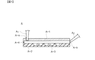
- FIG. 1 is a cross-sectional view of the microfluidic device A.
- FIG. 2 is a top view of the microfluidic device A.
- FIG. FIG. 3 is an exploded view of the microfluidic device A.
- FIG. 4 shows an example of a chemical structural formula of a bonding portion at the time of gelation between the first component and the second component that are gelling components, and a decomposition portion when light having a wavelength at which the gel decomposes is irradiated. It is an example of the chemical structural formula.
- FIG. 5 is a diagram showing a state in which a test cell is fixed in the microwell by using the microfluidic device, the first liquid, and the second liquid.
- FIG. 6 is a conceptual perspective view in an analysis process of a cell sorter or a flow cytometer which is an example of the present invention.
- FIG. 7 is (a) a conceptual perspective view and (b) an action diagram in a cell acquisition process of a cell sorter or a flow cytometer which is an example of the present invention.
- FIG. 8 is a schematic diagram showing the overall configuration of the cell sorter 1 in the cell sorter 1 as an example of the present invention.
- FIG. 9 is a functional block diagram of the cell sorter 1 which is an example of the present invention.
- FIG. 9 is a flowchart of the cell analysis control process in the cell sorter 1 which is an example of the present invention.
- FIG. 11 is a flowchart of the cell acquisition control process in the cell sorter 1 which is an example of the present invention.
- FIG. 12 is a flowchart according to a modified example of the cell analysis control process in the cell sorter 1 which is an example of the present invention.
- FIG. 13 is a diagram showing a synthesis scheme of the photodegradable hydrogel material used in the examples.
- FIG. 14 is a photograph showing that cells are stored and fixed in the microwell in Example 1.
- FIG. 15 is a fluorescence microscopic image of HL60 cells subjected to fluorescent staining immobilized on microwells in Example 2.
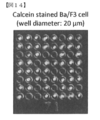
- FIG. 16 is a fluorescence microscopic image of fluorescent protein-expressing Ba / F3 cells immobilized in microwells in Example 3.
- FIG. 17 is a fluorescence microscopic image of fluorescent protein-expressing Ba / F3 cells immobilized in microwells in Example 4.
- FIG. 18 shows a conventional cell sorting technique.
- the “subject” in the present invention is not particularly limited, and examples thereof include cells and beads (for example, beads carrying a target component such as a virus).
- “cell” which is a preferred embodiment of the present invention will be described as an example of “subject”.
- the “degradable gel” in the present invention is not particularly limited as long as it is a gel that can be decomposed by applying a predetermined treatment, and is a gel that can be decomposed by energy (for example, light, sound, or heat), or a decomposition agent. The gel which can be decomposed
- “photodegradable gel” which is a preferred embodiment of the present invention will be described as an example of “degradable gel”. In addition, it demonstrates according to the following items. In addition, in the following description, even when described as “cell sorter” or “flow cytometer”, the term “flow cytometer” or “cell sorter” is also included.
- (1. Cell sorting method) 1-1. Filling step 1-1-1. Microfluidic device structure 1-1-2. First liquid flowing in the microfluidic device 1-1-2-1. First component and second component, basic skeleton, part 1 / part 2, photodegradable part 1-1-3. Second liquid flowing into the microfluidic device 1-1-4. Process 1-2. Detection step 1-3. Analysis step 1-4. Acquisition process (2. Cell sorter) 2-1. Microfluidic device 2-2. Laser beam irradiation unit 2-3. Signal detection unit 2-4. Light irradiation part for gel decomposition
- the cell sorting method includes: A flow step of flowing a liquid containing test cells into a flow path having a plurality of microwells, and filling the test cells in the microwells; After the filling step, the signal detection step of irradiating the microwell with an information source wave (for example, laser light) and detecting a signal resulting from the irradiation; Based on the signal in the signal detection step, an analysis step for analyzing the test cells filled in the microwells; An acquisition step of taking out the test cells after the analysis step.
- an information source wave for example, laser light
- the first liquid containing the test cells is caused to flow through the flow path (microfluidic device) having the microwells, and the test cells are filled in the microwells.
- the filling process will be described in detail with reference to FIGS.
- FIG. 1 is a cross-sectional view of the microfluidic device A
- FIG. 2 is a top view of the microfluidic device A
- FIG. 3 is an exploded view of the microfluidic device.
- the microfluidic device A has a planar structure in which a gap is provided between the upper surface A-1 and the lower surface A-2.
- the microfluidic device A has an insertion port Aa for introducing liquid into the gap (introduction for liquid insertion inserted into the insertion port Aa).
- a large number of microwells A-3 are provided on the lower surface of the microfluidic device A.
- the diameters of the microwells are 20 ⁇ m, 30 ⁇ m, and 40 ⁇ m, but are not limited thereto.
- the diameter of the microwell is appropriately selected depending on the size of the target cell, and is preferably 10 to 50 ⁇ m. In the case of general mammalian cells, the thickness is more preferably 15 to 30 ⁇ m.
- the well density in the microfluidic device A is not particularly limited, but is 100 to 10,000 / mm 2 from the viewpoint of capturing single cells with high efficiency. In the case of general mammalian cells, the number is more preferably 500 to 2,000 cells / mm 2 . If the density is lower than the preferred well density, the number of cells that can be processed in one analysis is reduced. Further, the upper limit of the well density is determined by the density when the preferred diameters are arranged in a close-packed manner.
- the microfluidic device includes at least a flow path through which a liquid can pass, a plurality of microwells provided on a wall surface of the flow path, an inlet for injecting fluid into the flow path, and the flow path An outlet for discharging fluid from the outlet.
- a cell adhesion inhibiting component for example, BSA, PEG, MPC (2-methacryloyloxyethyl phosphorylcholine), agarose, etc. ⁇ . It is preferable to do.
- the height of the side wall (the distance between the upper surface A-1 and the lower surface A-2) can be appropriately designed according to the size of the well used, the properties of each liquid to be injected into the microfluidic device, the injection conditions, and the like. .
- the microfluidic device A has an upper surface A-1 and a lower surface A-2 formed of different members, and is interposed between the upper surface A-1 and the lower surface A-2.
- the upper surface A-1, the lower surface A-2, and the side wall A-4 are integrally formed.
- the upper surface A-1 and the lower surface A-2 of the microfluidic device A have a planar structure, but the present invention is not limited to this, and fine irregularities may be provided.
- the flow path of the first liquid containing the test cells is planar.
- the microwell is preferably provided on the lower wall of the upper and lower walls (that is, the lower surface A-2 in this example) as in this example.
- the microwell may be provided on the upper wall (upper surface A-1), the side wall A-4, or the like constituting the flow path according to the application.
- the first liquid that flows into the microfluidic device is a liquid that contains a plurality of test cells, and includes a first component and a second component that is different from the first component.
- the first component and the second component react with time and gel.
- the first component and the second component exist in a state dissolved in a liquid (for example, a liquid in which cells can survive, for example, physiological saline or liquid medium).
- a liquid for example, a liquid in which cells can survive, for example, physiological saline or liquid medium.
- first component and the second component are gelled materials.
- the first component has a first portion whose basic skeleton is a biocompatible polymer and can be bonded to the second component.
- the second component has a second part whose basic skeleton is a biocompatible polymer and can be bonded to the first component.
- the first component and / or the second component further has a photodegradable portion.
- the “basic skeleton”, “first / second part”, and “photodegradable part” of the first and second components will be described in detail.
- the biocompatible polymer constituting the basic skeleton is not particularly limited, and is a carbohydrate-based polymer (methyl cellulose, carboxymethyl cellulose, hydroxymethyl cellulose, hydroxypropyl cellulose, hydroxyethyl cellulose, ethyl cellulose, dextrin, cyclodextrin, alginate, hyaluronic acid and Chitosan, etc.); protein-based polymers (gelatin, collagen and glycol proteins, etc.); hydroxy acid polyesters (biodegradable polylactide-coglycolide (PLGA), polylactic acid (PLA), polyglycolide, polyhydroxybutyric acid, polycaprolactone, poly Valerolactone, polyphosphazene and polyorthoester, etc.); albumin; polyanhydride; polyethylene glycol Polyvinyl polyhydroxyalkyl methacrylates; pyrrolidone, polyvinyl alcohol.
- carbohydrate-based polymer methyl cellulose, carboxymethyl cellulose,
- polyethylene glycol is preferred.
- multi-arm PEG for example, 2-arm, 4-arm, 8-arm
- the weight average molecular weight of PEG is preferably 500 to 100,000, and more preferably 2,000 to 40,000. Since such PEG has little influence on the cells, it is excellent in that the cells can be collected in a form that does not impair the functions inherent to the cells (in other words, the cells can be collected while alive).
- the weight average molecular weight is a value measured by MALDI-TOF-MS.
- the first part bonded to the basic skeleton of the first component is the basic of the second component that constitutes the gel. It can be bonded to the second part bonded to the skeleton (or the first part bonded to the basic skeleton of the first component).
- Examples of such a combination of the first part and the second part include, for example, an azide group and an alkyne group (cycloaddition reaction), an azide group, which is a combination of reactive groups that form a chemical bond in liquid.
- Dibenzocyclooctyne group (cycloaddition reaction), thiol group and maleimide group (Michael addition reaction), thiol group and iodoacetamide group, thiol group and vinylsulfone group, aldehyde group and hydrazine group, ketone group and hydrazine group, aldehyde group And aminooxy groups, ketone groups and aminooxy groups, protein and ligand combinations that form chemical bonds or strong interactions, biotin and streptavidin, maltosyl and maltose binding proteins, glutathionyl and glutathione S-transferase, HaloTag® ligand and H loTag® protein, guanylylmethylphenyl group and SNAP-tag®, cytosynylmethylphenyl group and CLIP-tag, Strep-tag® and Strep-tactin®, antigen and Mention may be made of antibodies.
- a combination of an azide group and an alkyne group is preferable because it hardly reacts with a functional group on the cell surface.
- the modification of the first part and the second part to the biocompatible polymer can be performed by a known method.
- the photodegradable part may be present in one or both of the first component and the second component.
- the photodegradable moiety refers to any group that can be eliminated by light irradiation.
- nitrobenzyl group nitrophenylethyl ester group (NPE), dimethoxynitrobenzyl ester group (DMNB), bromohydroxycoumarin (Bhc).
- FIG. 4 shows an example of a chemical structural formula of a bonding portion at the time of gelation between the first component and the second component, which are gelling components, and light irradiation (light having a wavelength at which the gel decomposes).
- the first component is 4-arm PEG-PL-azide (photodegradable 2-nitrobenzyl derivative skeleton is bonded to 4-arm PEG, and azide is further bonded to 2-nitrobenzyl derivative skeleton.
- the second component is 4-arm PEG-DBCO (dibenzylcyclooctyne linked to 4-arm PEG). After these are added and mixed in the liquid, a bridge is formed between the azide and DBCO.
- the 1st liquid contains a 1st component and a 2nd component at the time of use as mentioned above.
- the first component before use, that is, when the first liquid is transported or stored, the first component is preferably contained to prevent the gelation reaction between the first component and the second component before use.
- a kit comprising at least two liquids: a liquid and a liquid containing a second component.
- Second liquid flowing in microfluidic device ⁇ After flowing the first liquid containing the test cells and the gelling material through the gap of the microfluidic device A, the first liquid is removed outside the microwell by flowing the second liquid.
- the 2nd liquid used in this case is not specifically limited, The component which is incompatible with 1st liquid, for example, oil, is suitable.
- FIG. 5 is a diagram showing a state in which a test cell is fixed in a microwell by using the above device and solution.
- the first liquid (gel solution) is injected into the inside from the introduction port of the microfluidic device ((a) in the figure). This operation is repeated a plurality of times (5 to 10 times in the example in the figure) ((b) in the figure). By this operation, cells can be filled into the microwell with high efficiency. However, the injection operation may be performed once. Thereafter, the second liquid (oil) is injected from the introduction port of the microfluidic device into the inside, and the excess first liquid existing inside is discharged out of the microfluidic device ((c) in the figure). Then, it incubates on predetermined conditions, the gel material (1st component and 2nd component) in a microwell is gelatinized, and the cell accommodated in the microwell is fix
- the first solution (gel solution) is filled in the microwells before gelation, but is not limited thereto. More specifically, the first liquid (gel solution) around the test cell is in a gelled state, and the first liquid (gel solution) is not gelated in the entire first liquid. It is preferable to inject from the introduction port of the microfluidic device. By setting it as such a process, the test cell can be filled in a microwell in the form which the gel around a test cell functions as a protective material, and does not impair the function which a cell originally has.
- Signal detection from a test cell fixed by a gel in a microwell can be the same as the detection method used in a conventionally known flow cytometry or cell sorter.
- detection is obtained by irradiating a microwell to be detected with laser light (for example, single laser or dual laser such as argon, diode, die, helium neon, etc.), and resulting from the irradiation.
- laser light for example, single laser or dual laser such as argon, diode, die, helium neon, etc.
- FSC Signal ⁇ forward scattered light
- SSC side scattered light
- various fluorescence of the fluorescence-labeled cell ⁇ can be measured.
- a wave serving as an information source is not particularly limited, and examples thereof include electromagnetic waves having appropriate wavelengths such as gamma rays to microwaves, and sound waves.
- the analysis can be the same as the detection method used in a conventionally known flow cytometry or cell sorter.
- the size of the cell, the complexity of the internal structure of the cell, and the like can be analyzed through analysis based on the signal (data) obtained in the detection step.
- more detailed analysis such as cell imaging (for example, dynamic analysis of cell membrane molecules, analysis of cell chromosomes) can be performed.
- One feature of the present invention is that a test cell is fixed in a microwell, so that a plurality of items can be analyzed simultaneously.
- Acquisition process is performed by irradiating light (wavelength light that decomposes the photodegradable gel in which the test cells are embedded in the microwells) to the microwells containing the test cells to be acquired. .
- the photodegradable gel in the microwell irradiated with the light is decomposed and the test cells in the microwell are fixed (falling below the microwell).
- a liquid eg, physiological saline
- the test cells are discharged together with the liquid (in addition, as the liquid released into the flow path in such an acquisition process, (Eg, physiological saline, liquid medium, etc.) can be suitably used.
- emitted with the liquid is acquired.
- one feature of the present invention is that various types of desired cells can be selectively obtained from the same array.
- an example in which analysis is performed immediately after embedding cells in a microwell with a gel to obtain desired cells is not limited thereto.
- the cells after embedding the cells in a microwell with a gel, the cells may be cultured in the wells (for example, by culturing for a long time) by flowing a culture solution, and the cells after the culture may be analyzed. .
- a cell sorter or flow cytometer 1 which is an example of the present invention, A flow path (microfluidic device) 1-1 having a plurality of microwells 1-1-a; A laser beam irradiation unit 1-2 capable of emitting a laser beam to one microwell of the plurality of microwells 1-1-a; When the laser beam irradiation unit 1-2 irradiates the one microwell with a laser beam, a signal detection unit 1-3 for detecting a signal generated due to the irradiation; Based on the signal from the signal detection unit 1-3, an analysis unit (not shown) for analyzing a test cell in the one microwell; The laser beam irradiation unit 1-2, the signal detection unit 1-3, and the analysis unit (not shown) are configured to apply the irradiation and the processing to all of the plurality of microwells 1-1-a.
- a cell sorter 1 configured to perform detection and analysis,
- the microwell 1-1-a can store a test cell and a photodegradable gel,
- the cell sorter 1 After the analysis by the analysis unit (not shown), light for decomposing the photodegradable gel, which is irradiated with light having a wavelength different from that of the laser beam 1-4 It has further.
- each part will be described in detail.
- the laser beam irradiation unit 1-2 is configured to be able to irradiate each of the plurality of microwells 1-1-a independently.
- it is configured to be movable (front and rear, left and right) directly below (or directly above) each of the plurality of microwells 1-1-a (so-called scanning type).
- the signal detection unit 1-3 which will be described later, is also configured to be movable (front and rear, left and right) following the movement of the laser beam irradiation unit 1-2 (see FIGS. 6A and 6B). ).
- the method of independently irradiating each of the plurality of microwells 1-1-a is not limited to this, and, for example, the laser beam irradiation unit 1-2 is irradiated by swinging under a fixed condition.
- Irradiation method for example, a method of forming a linear light source by arranging laser beam irradiation units in a line, or a surface that can irradiate light to a plurality of microwells in a certain area with a certain range as one section Or a method of irradiating a plurality of microwells all at once (using a light source capable of irradiating light to all the microwells).
- a plurality of analyzes are performed simultaneously, a plurality of laser beam irradiation units may be provided corresponding to the type of analysis. Further, the laser beam irradiation unit may be configured to change the type of detection wave and to perform a plurality of analyzes simultaneously.
- the light is irradiated from directly below (or directly above) the microwell 1-1-a.
- the light is irradiated obliquely below (or obliquely above) the microwell 1-1-a.
- the form which performs irradiation may be sufficient.
- the signal detection unit 1-3 detects a signal emitted when the laser beam is irradiated to the test cell by the laser beam irradiation unit 1-2. Similar to the laser beam irradiation unit 1-2, it is necessary to detect the signals of the plurality of microwells 1-1-a. Therefore, in the example of FIG. 6, as described above, the movement of the laser beam irradiation unit 1-2 is performed. Is configured to be movable (front and rear, right and left) (see FIGS. 6A and 6B). Note that the method of detecting the signals of each of the plurality of microwells 1-1-a is not limited to this.
- a method of providing the signal detection units 1-3 by the number of the plurality of microwells 1-1-a A method for detecting signals from microwells (for example, a method in which a plurality of signal detectors 1-3 are arranged in a line, or a certain range as one section, and signals from a plurality of microwells in the one section are detected. Or a technique for detecting signals from a plurality of microwells at once. For example, when the signal detection unit is a microscope, the configuration can be changed as appropriate, such as imaging each microwell or imaging a plurality of microwells simultaneously.
- a plurality of signal detection units 1-3 may be provided corresponding to the type of analysis (for example, a plurality of signal detection units are provided in a form corresponding to one microwell. Installed).
- the signal detection unit 1-3 is shown on the opposite side of the laser beam irradiation unit 1-2 through the surface (flow path) where the microwell 1-1-a exists.
- the present invention is not limited to this, and can be appropriately changed depending on the type of signal to be detected, such as being on the same side as the laser beam irradiation unit 1-2.
- the gel-decomposing light irradiation unit 1-4 is configured to be able to irradiate each of the plurality of microwells 1-1-a independently.
- FIG. 7 from the viewpoint of simplifying the drawing, it is described as the same as the laser beam irradiation unit 1-2, but the light of the laser beam irradiation unit 1-2 and the light beam irradiation unit for gel decomposition 1-4 Since the wavelength of this light is different, it is usually a different light source.
- the gel decomposition light irradiation unit and the laser beam irradiation unit may be the same light source.
- a light source in which a plurality of light sources (laser beam irradiation unit 1-2 and gel decomposition light irradiation unit 1-4) are unitized may be used.
- the gel-decomposing light irradiation unit 1-4 can also be moved directly below (or directly above) each of the plurality of microwells 1-1-a in the example of FIG. Front / rear / left / right).
- the method of independently irradiating each of the plurality of microwells 1-1-a is not limited to this, and for example, the gel decomposition light irradiation unit 1-4
- the method of changing the position of the microwell 1-1-a that is irradiated by swinging under a fixed state, or the gel-decomposing light irradiation unit 1-4 is connected to a plurality of microwells 1-1-a. A method of providing only the number may be used.
- a confocal laser microscope etc. can be illustrated as a specific example of an apparatus which has a laser beam irradiation part and a signal detection part. More specifically, a plurality of cells are simultaneously imaged (microscopic analysis) with a confocal laser microscope to select the cells. Then, use the CLSM ROI (Region of Interest) mode to irradiate wells containing the target cells, and irradiate only that part with light of the photolysis wavelength (for example, 405 nm light) to decompose the gel, etc. do it.
- the CLSM ROI Registered of Interest
- various liquids can be sent from the inlet 1-1-b of the microfluidic device 1, and the decomposed gel or the like is discharged from the outlet 1-1 of the microfluidic device 1.
- -C is configured to be discharged from the outlet, and a box 1-6 is provided at the outlet 1-1-c for collecting the discharged liquid and the cells contained in the gel (such liquid feeding, Ejection, cell recovery, etc. may be performed by appropriate means as necessary).
- the cell sorter 1 of this example includes a laser beam irradiation unit 1-2 (laser irradiation unit 1-2) and a laser irradiation unit capable of laser beam irradiation corresponding to one microphone well shown in FIGS.
- a signal detection unit 1-3 capable of detecting a signal derived from the light irradiation of 1-2 and a light irradiation unit for gel decomposition 1-4 capable of light irradiation corresponding to one microphone well, It is configured to be movable (front / back / left / right).
- FIG. 8 is a schematic diagram showing the overall configuration of the cell sorter 1 of the present invention.
- the cell sorter 1 includes a processing unit 100 having a CPU, a ROM area, and a RAM area, a signal detection unit 1-3, a laser irradiation unit 1-2, and a gel decomposition light irradiation unit 1. -4, a phase liquid unit 2, a cell recovery unit 3, and a display unit 4.
- the liquid feeding unit 2 is a device capable of filling various liquids (the liquids such as the first liquid, the second liquid, and the physiological saline described above) in the microfluidic device 1-1, and the inside of the apparatus. By changing the flow path, the liquid can be appropriately selected and switched.
- the cell collection unit 3 is an apparatus (for example, the above-described box 1-6) that can collect cells discharged from the microwell 1-1-a.
- the display unit 4 is a device that can display various data (for example, cell information described later) of the processing unit 100 as an image. Other configurations are the same as described above, and will be omitted.
- FIG. 9 is a functional block diagram of the cell sorter 1 of this example.
- the processing unit 100 includes a detection device control unit 110 capable of controlling the device related to the analysis process / detection step, a gel decomposition device control unit 120 capable of controlling the device related to the acquisition process, and a transmission unit.
- the liquid feeding control unit 130 that can control the liquid unit 2 and the cell collection control unit 140 that can control the cell acquisition behavior of the cell collection unit 3 (for example, opening / closing of the opening for introducing cells, the position of the opening, etc.).
- the information storage unit 150, the cell information determination unit 160 capable of making various determinations based on the cell information stored in the information storage unit 150, and the display control capable of controlling the video output of the display unit 4 Part 170.
- the detection device having the laser irradiation unit 1-2 and the signal detection unit 1-3, the gel decomposition device having the gel irradiation light irradiation unit 1-4, The liquid unit 2, the cell collection unit 3, and the display device 4 are electrically connected to the processing unit 100.
- the detection device control unit 110 also controls the laser irradiation control unit 111-1 that can control the laser irradiation mode (irradiation time, irradiation intensity, etc.) in the laser irradiation unit 1-2, and the microwell of the laser irradiation unit 1-2.
- a laser irradiation position control unit 111-2 capable of controlling the irradiation position
- a signal detection control unit 121-1 capable of controlling a detection mode (detection time, etc.) of the signal detection unit 1-3
- a signal detection position control unit 112-2 capable of controlling the detection position with respect to the microwell.
- the gel decomposition apparatus control unit 120 includes a gel decomposition light irradiation control unit 121-1 capable of controlling the light irradiation mode (irradiation time, irradiation intensity, etc.) in the gel decomposition light irradiation unit 1-4, and a gel decomposition light source.
- a gel-decomposing light irradiation control unit 121-2 capable of controlling the irradiation position of the light irradiation unit 1-4.
- FIG. 10 is a flowchart relating to cell analysis control processing (step 1000) in the cell sorter 1.
- step 1001 the processing unit 100 determines whether cell analysis control is started. In the case of Yes in step 1001, in step 1002, the liquid feeding control unit 130 feeds the cell-containing liquid (first liquid) from the liquid feeding unit 2 into the microfluidic device 1-1, and the microfluidic device 1- Fill the microwell in 1 with the cell-containing solution.
- step 1004 the liquid feeding control unit 130 feeds oil from the liquid feeding unit 2 into the microfluidic device 1-1, and eliminates excess cell-containing liquid in the microfluidic device 1-1. (Note that the liquid fed in Step 1004 is not limited to oil, and may be the second liquid described above).
- step 1006 the processing unit 100 performs initial setting processing of the laser irradiation unit 1-2 and the signal detection unit 1-3 (in this example, the variable n and each microwell in the microfluidic device 1-1). 1 is substituted for n in a situation where the position information is associated with the position information).
- step 1008 the laser irradiation position control unit 111-2 and the signal detection position control unit 112-2 move the laser irradiation unit 1-2 and the signal detection unit 1-3 to the position n.
- step 1010 the laser irradiation control unit 111-1 irradiates the microwell existing at the position n from the laser irradiation unit 1-2 (at this time, the signal detection unit 1- 1).
- step 1012 the processing unit 100 temporarily stores cell information related to cells existing in the microwell irradiated with the detection laser in the information storage unit 150 based on the signal detected by the signal detection unit 1-3. (In this case, as an example, even if there is no cell in the well, the cell information is temporarily stored. However, if there is no cell in the well, cell information on the corresponding microwell is stored. May not be stored).
- step 1014 the processing unit 100 determines whether or not irradiation of the detection laser to all the microwells has been completed (whether n has reached fin). If Yes in step 1014, the process proceeds to step 1018.
- step 1016 the processing unit 100 adds 1 to n and proceeds to step 1008.
- step 1018 the cell information determination unit 160 refers to all the temporarily stored cell information ⁇ in this example, the number of cell information equal to the total number (n) of microwells ⁇ and is set in advance. Based on the determination information, it is determined whether each cell is a desired cell.
- step 1020 the cell information determination unit 160 determines whether or not a desired cell exists in the microwell. In the case of Yes at step 1020, the processing unit 100 temporarily stores the position information of the microwell where the desired cell exists in the information storage unit 150, and proceeds to step 2000.
- step 1000 the cell analysis control process
- step 1006 to step 2000 are performed. You may repeat until.
- the variable n and the position information of each microwell in the microfluidic device 1-1 are associated, but the position information of the microwell may be the position information of the microwell itself.
- the surface on which the microwell is provided may be appropriately classified (grouped), and information relating to the classification may be used, and is not limited at all.
- microwell position information may be incorporated in advance in the processing unit 100, or the microwell position may be automatically determined by an optical method or the like.
- the configuration of the present example in which the laser irradiation unit 1-2 moves to the next microwell after completing the analysis for one microwell (the laser irradiation unit 1-2). It is not limited to the configuration in which the stop and the movement are repeated.
- the laser irradiation unit 1-2 may be configured to be able to move continuously across a plurality of microwells (a configuration in which a certain range of analysis is performed at a constant speed like a scanner). In this case, since the position where the desired cell information is acquired can be read as the microwell position information even if the microwell position does not exist, the setting of the microwell position information in advance is not necessary ( The analysis start condition and end condition may be changed as appropriate).
- the configuration allows analysis of a plurality of microwells by one laser irradiation. May be.
- the laser irradiation portion 1-2 is used. Since all the cell information can be acquired with the laser beam stopped, the laser irradiation unit 1-2 does not need to move. In this example, the laser irradiation unit 1-2 itself moves. However, as described above, the laser irradiation unit 1-2 is swung, or the irradiation angle is changed by a reflecting plate. A configuration may be adopted in which the microwell for analysis is changed.
- the detection laser emitted from the laser irradiation unit 1-2 used in the analysis step is not limited to laser light, and has a function capable of irradiating an appropriate information source wave capable of acquiring cell information.
- the laser irradiation unit 1-2 has a configuration capable of oscillating a plurality of information source waves (that is, a configuration capable of changing the oscillation wavelength and frequency, and a configuration including a plurality of oscillation terminals).
- a plurality of laser irradiation units 1-2 may be provided depending on the type of information source wave to be oscillated.
- the configuration of the signal detection unit 1-3 may be changed as appropriate, and there is no limitation as long as signal detection is possible.
- the cell information related to all the plurality of microwells may be configured to be detected by a single fixed signal detection unit 1-3 (in this case, the signal detection unit 1-3). The control related to the movement is unnecessary.)
- the signal detector 1-3 may be configured to have one signal detector 1-3 for one information source wave, or one signal The detection unit 1-3 may be configured to detect a plurality of signals.
- step 1000 in the cell analysis control process (step 1000), after step 1004, in order to gel the components in the cell-containing liquid (first liquid), a subsequent process may be waited (or Or a treatment for promoting gelation may be interposed).
- a subsequent process may be waited (or Or a treatment for promoting gelation may be interposed).
- step 1002 and step 1004 after preparing a plurality of microfluidic devices 1-1 and executing the processing according to step 1002 and step 1004 for one microfluidic device 1-1, successively for another microfluidic device 1-1.
- the processing according to step 1002 and step 1004 may be executed.
- the processing according to Step 1002 and Step 1004 can be executed for another microfluidic device 1-1 during the waiting time required for gelation of components in the cell-containing liquid in one microfluidic device 1-1. It is good.
- the components in the cell-containing liquid in the microfluidic device 1-1 may be shifted to the next process sequentially from the gelled component.
- FIG. 11 is a flowchart of the cell acquisition control process (step 2000) in the cell sorter 1.
- the processing unit 100 refers to the information storage unit 150, and reads position information of a predetermined microwell that is determined to have a desired cell.
- the processing unit 100 performs an initial setting process for the gel-decomposing light irradiation unit 1-4 (the variable m is linked to the position information of a predetermined microwell in the microfluidic device 1-1). Under the circumstances, 1 is substituted into m).
- step 2006 the gel-decomposing light irradiation position control unit 121-2 moves the gel-decomposing light irradiation unit 1-4 to the position m.
- step 2008 the gel decomposition light irradiation control unit 121-1 irradiates the gel decomposition laser to the microwell existing at the position m from the gel decomposition light irradiation unit 1-4.
- step 2010, the liquid feeding control unit 130 sends a liquid (eg, physiological saline) from the liquid feeding unit 2 into the microfluidic device 1-1 as a liquid feeding process (at this time, it is decomposed). And the cells contained in the gel are transferred out of the microwell).
- a liquid eg, physiological saline
- step 2012 the cell recovery control unit 140 controls the cell recovery unit 3 as a cell acquisition process, and together with the fed liquid, the decomposed gel and the cells contained in the gel are stored in the cell recovery unit. Collect in 3.
- step 2014 the processing unit 100 determines whether or not the gel decomposition laser has been irradiated to all the predetermined microwells. If Yes in step 2014, the cell acquisition control process 2000 ends. On the other hand, in the case of No in step 2014, in step 2016, the processing unit 100 adds 1 to m, and proceeds to step 2006.
- one microwell is irradiated with a single laser for gel decomposition.
- a single laser is used.
- disassembly with respect to several microwells by irradiation may be sufficient.
- the gel decomposition light irradiation unit 1-4 itself moves, but as described above, the gel decomposition light irradiation unit 1-4 is swung or irradiated by a reflector.
- the microwell for performing gel decomposition may be changed by changing the angle or the like (in this case, gel decomposition can be performed in all wells while the gel decomposition light irradiation unit 1-4 is stopped).
- the gel-decomposing light irradiation unit 1-4 may not move).
- the cell analysis control process (step 1000) and the cell acquisition control process (step 2000) are continuous processes, but these may be independent processes.
- FIG. 12 is a flowchart of the cell analysis control process (S1000-2) according to a modified example of the cell analysis control process (S1000) in the cell sorter 1 which is an example of the present invention.
- S1000 cell analysis control process
- step 1019-2 the display control unit 170 refers to the information storage unit 150 and displays information related to cell information on the display device 4.
- step 1020-2 the processing unit 100 determines the desired cell in the microwell based on selection information described later (in this example, information input to the processing unit 100 by the operator using an input terminal or the like). It is determined whether or not it is determined that exists. If Yes in step 1020-2, the process proceeds to cell acquisition control processing (step 2000).
- the process can be interrupted between step 1019-2 and step 1020-2.
- step 1020-2 that is, while the processing is interrupted, the operator observes the cell information displayed on the display device 4 (for example, display), for example, and whether or not a desired cell exists. Judgment is made.
- the selection information (whether there is a predetermined microwell in which a desired cell exists and the position of the predetermined microwell, etc.) related to the result of the determination is processed by the processing unit 100 (information storage unit 150) using an input terminal or the like. And is referred to by the processing unit 100 in step 1020-2.
- the processing unit 100 may not include the cell information determination unit 160.
- the cell sorter 1 may be in a mode in which a manual operation is performed on a part of the cell sorter 1 (a mode in which the operator appropriately determines and performs various processes based on the determination).
- a cell-containing liquid feeding process an oil feeding process, a liquid feeding (for example, physiological saline) process, cell acquisition, and the like may be performed manually as appropriate.
- Example 1 (Synthesis of gel material)
- the gel material used in this example was synthesized based on the synthesis scheme of FIG.
- a detailed synthesis method of 4-arm PEG-azide and 4-arm PEG-DBCO, which are gel materials used in this example will be described.
- the number of repetitions n of the starting 4-arm PEG-amine is about 111.
- Synthesis of Compound 2 The reaction was performed in the dark.
- the tube was centrifuged (4 ° C, 10 krpm, 10 min), the supernatant was decanted and allowed to stand at room temperature, and then vacuum dried in a desiccator to remove diethyl ether.
- the dialysis membrane was dialyzed for 3.5 days.
- the white solid of the desired 4-arm PEG-PL-azide was obtained by lyophilization. The yield was 80 mg and the yield was 49%.
- a liquid was obtained.
- the cell density is 50,000,000 cells / mL, and the concentration of the gel material is 0.9 w / v%.
- Example 2 HL60 cells subjected to calcein staining were immobilized in the same manner as in Example 1, except that a photodegradable hydrogel modified with a red fluorescent dye was used. Thereafter, light (405 nm) was irradiated to specific cell groups, and the gels in these microwells were dissolved. Thereafter, these cells were selectively obtained by flowing a liquid (buffer solution under physiological conditions).
- FIG. 1 HL60 cells subjected to calcein staining were immobilized in the same manner as in Example 1, except that a photodegradable hydrogel modified with a red fluorescent dye was used. Thereafter, light (405 nm) was irradiated to specific cell groups, and the gels in these microwells were dissolved. Thereafter, these cells were selectively obtained by flowing a liquid (buffer solution under physiological conditions).
- FIG. 15a is an image of a cell immobilized in a microwell with a photodegradable hydrogel (superimposed image of a green fluorescence and a red fluorescence image and a bright field image), and a portion surrounded by a square is light. It is a microwell irradiated with (405 nm).
- FIG. 15b is an image of cells immobilized with a photodegradable hydrogel in a microwell after being washed a predetermined number of times (in this example, 15 times) with a liquid (buffer solution under physiological conditions) after light irradiation. is there. As can be seen from FIG. 15b, in this example, a plurality (seven cells in this example) of cell groups could be obtained collectively.
- FIG. 16 is a fluorescence microscopic image of fluorescent protein-expressing Ba / F3 cells immobilized in a microwell ⁇ a is a superimposed image (low magnification) of a green fluorescent image and a red fluorescent image, b is Superposed image (high magnification) of green fluorescence and red fluorescence image and bright field image ⁇ .
- red fluorescence is emitted from cells mainly emitting green is that light emitted as scattered light from the cells themselves was detected when laser light emitting red fluorescence was irradiated.
- green fluorescence is emitted only from cells expressing EGFP, and no green fluorescence is emitted from cells expressing Kusecuring-Orange.
- microwells containing two cells such microwells can be identified by comparing a fluorescent image and a bright field image.
- FIGS. 17a to 17d are images of cells immobilized with a photodegradable hydrogel in a microwell (superposed images of green fluorescence and red fluorescence images and bright field images). Although it is difficult to understand from the figure, there are microwells that emit only green fluorescence, microwells that emit only red fluorescence, and microwells that emit red and green fluorescence.
- FIG. 17a to 17d are images of cells immobilized with a photodegradable hydrogel in a microwell (superposed images of green fluorescence and red fluorescence images and bright field images).
Abstract
[Problem] To provide an automatable cell acquisition technique by which a plurality of cells can be simultaneously analyzed while reducing the frequencies of false positives and false negatives.
[Solution] A cell sorter or flow cytometer comprising a flow passage provided with a plurality of microwells, an introduction passage capable of introducing a liquid, said liquid containing a plurality of target cells, into the flow passage, a data acquisition part acquiring data from the target cells housed in the microwells, a selective taking-out means capable of selectively taking out the target cells, said target cells being in the microwells, from the microwells on the basis of the data acquired by the data acquisition part, and a target cell collection part capable of collecting the target cells selectively taken out by the selective taking-out means, characterized in that: the microwells can house the target cells and a photodegradable gel; and the selective taking-out means is a degrading light-irradiation part capable of irradiating the photodegradable gel, said photodegradable gel being in a microwell housing a target cell to be taken out, with light having a wavelength at which the photodegradable gel degrades.
Description
本発明は、新規なセルソーティング方法、並びにこれを利用したフローサイトメトリー及びセルソーターに関する。
The present invention relates to a novel cell sorting method, and a flow cytometry and cell sorter using the same.
フローサイトメトリーは、蛍光色素でラベルした抗体等をターゲット細胞に結合させ、その蛍光や散乱光によって粒子を分析・分離する手法をいう。この際、細胞等の微粒子集団から特定の細胞(微生物を含む)を分離する手法が、セルソーティング技術である(非特許文献1等)。セルソーティング技術は、細胞挙動や細胞機能を理解する上で、非常に重要な方法である。
Flow cytometry is a technique in which antibodies labeled with a fluorescent dye are bound to target cells, and particles are analyzed and separated by the fluorescence and scattered light. At this time, a technique for separating specific cells (including microorganisms) from a population of fine particles such as cells is a cell sorting technique (Non-patent Document 1). Cell sorting technology is a very important method for understanding cell behavior and cell function.
非特許文献1の技術(図18参照)では、蛍光色素等でラベルした抗体を結合させたターゲット細胞の懸濁液を液流とし、まず、その流路内で該細胞に、標識した蛍光色素に応じて励起光を照射し、各細胞から発する蛍光又は散乱光の波長や強度を解析して所望の細胞を識別する。次いで、上記光の波長や強度等の解析結果によって識別された特定の性質を有する細胞に電圧を印加して帯電させ、偏向電極を利用して上記で帯電された細胞の弁別、定量、統計解析等を行う。
In the technique of Non-Patent Document 1 (see FIG. 18), a suspension of target cells to which an antibody labeled with a fluorescent dye or the like is bound is used as a liquid flow. In response to the excitation light, the desired cells are identified by analyzing the wavelength or intensity of the fluorescence or scattered light emitted from each cell. Next, voltage is applied to the cells having specific properties identified by the analysis results such as the wavelength and intensity of the light, and the cells are charged by using a deflection electrode to discriminate, quantify and statistically analyze the charged cells. Etc.
このように、従来のセルソーティング技術は、流路に沿って流れてくる1個1個の細胞を順番に解析し、回収する技術である。より具体的には、検出部を通過する瞬間の細胞から発せられるシグナル(主に蛍光や散乱光)の絶対値で解析する技術である。したがって、多数の細胞について多数の項目について解析を行うことに対しては不向きである。しかも、当該技術は、偽陽性や偽陰性の発生も懸念される技術でもある。他方、偽陽性や偽陰性の頻度を少なくし且つ多数の細胞について多数の項目について解析を行う手法としては、マイクロアレイ技術がある。しかしながら、当該技術では、取得が望まれる細胞が見出された際、当該細胞が入っているマイクロウェルにマイクロマニピュレーターを挿入する手法にて当該細胞を取得するという点で、所望細胞取得の自動化には不向きである。したがって、本発明は、偽陽性や偽陰性の頻度を低減させつつ複数の被検体(例えば細胞)を同時に解析可能であり且つ自動化が可能な被検体(例えば細胞)取得技術を提供することを課題とする。
As described above, the conventional cell sorting technique is a technique for sequentially analyzing and recovering each cell flowing along a flow path. More specifically, the analysis is based on the absolute value of a signal (mainly fluorescence or scattered light) emitted from a cell at the moment of passing through the detection unit. Therefore, it is not suitable for analyzing many items for many cells. Moreover, this technique is also a technique that is concerned about the occurrence of false positives and false negatives. On the other hand, as a technique for reducing the frequency of false positives and false negatives and analyzing many items for many cells, there is a microarray technique. However, in this technique, when a cell desired to be acquired is found, the cell is acquired by a technique of inserting a micromanipulator into a microwell containing the cell. Is unsuitable. Therefore, it is an object of the present invention to provide a subject (eg, cell) acquisition technique that can simultaneously analyze a plurality of subjects (eg, cells) while reducing the frequency of false positives and false negatives and that can be automated. And
本発明は下記の通りである:
[1] 複数のマイクロウェルを有する流路と、
複数の被検体(例えば被検細胞)を含有する液を、前記流路に導入可能な導入路と、
前記複数のマイクロウェルに収納された複数の被検体(例えば被検細胞)から情報を取得する情報取得部と、
前記情報取得部が取得した情報に基づき、一のマイクロウェル内の被検体(例えば被検細胞)を当該マイクロウェル内から選択的に取り出し可能な選択取り出し手段と、
前記選択取り出し手段により選択的に取り出された被検体(例えば被検細胞)を回収可能な被検体(例えば被検細胞)回収部と
を有するセルソーター又はフローサイトメーターであって、
前記複数のマイクロウェルが、被検体(例えば被検細胞)及び分解性ゲル(例えば光分解性ゲル)を収納可能であり、
前記選択取り出し手段が、取り出されるべき被検体(例えば被検細胞)が保持されたマイクロウェル内の分解性ゲル(例えば光分解性ゲル)に対し、当該分解性ゲル(例えば光分解性ゲル)が分解する処理を施す(例えば当該光分解性ゲルが分解する波長の光を照射可能な)分解処理部(例えば分解光照射部)である
よう構成されたセルソーター又はフローサイトメーター。
[2] 前記流路が平面状であり、前記複数のマイクロウェルは、当該流路を構成する(上壁及び下壁の内の)下壁に設けられている、前記[1]のセルソーター又はフローサイトメーター。
[3] 前記分解性ゲルが、光分解性ゲルであり、
前記分解処理部は、前記光分解性ゲルが分解する波長の光を照射可能な光照射部である、前記[1]又は[2]のセルソーター又はフローサイトメーター。
[4] 前記情報取得部は、
前記複数のマイクロウェルからの前記情報を、マイクロウェル毎に取得、複数のマイクロウェルのうちの2以上のものについて一度に取得、又は前記複数すべてのマイクロウェルについて一度に取得可能である、前記[1]~[3]のセルソーター又はフローサイトメーター。
[5] 前記情報取得部は、
前記複数のマイクロウェルに対して、取得されるべき前記情報のソースとなる情報ソース波を照射可能な情報ソース波照射部と、
前記情報ソース波照射部が前記複数のマイクロウェルに対して前記情報ソース波を照射した際、前記複数のマイクロウェルから発生し得る前記情報を受信する情報受信部と
を有する、前記[1]~[4]のセルソーター又はフローサイトメーター。
[6] 前記情報ソース波照射部は、第一態様として、マイクロウェル毎に前記情報ソース波を照射可能であるか;第二態様として、複数のマイクロウェルのうちの2以上のものを一度に照射可能であるか;又は、第三態様として、前記複数すべてのマイクロウェルを一度に照射可能であり;前記第一態様及び前記第二態様の場合には、前記複数のマイクロウェルすべてを走査して照射し得る、前記[5]のセルソーター又はフローサイトメーター。
[7] 前記情報ソース波照射部は、解析項目の数に応じ、複数種の情報ソース波を出力可能である、前記[5]又は[6]のセルソーター又はフローサイトメーター。
[8] 前記情報ソース波照射部から照射される前記情報ソース波が光であり、前記分解性ゲルが光分解性ゲルであり、且つ、前記分解処理部が、前記光分解性ゲルが分解する波長の光を照射可能な光照射部である場合、当該光の波長は、前記光分解性ゲルが分解する光の波長とは異なる、前記[5]~[7]のセルソーター又はフローサイトメーター。
[9] 前記光照射部と前記情報ソース波照射部とが、同一光源であり、
前記同一光源は、前記光分解性ゲルが分解する波長の光と、取得されるべき前記情報のソースとなる、前記光分解ゲルが分解する前記波長とは異なる波長の光と、を切替照射可能に構成されている、前記[8]のセルソーター又はフローサイトメーター。
[10] 前記セルソーター又はフローサイトメーターは、
前記情報取得部で取得した前記情報を自動解析する自動解析手段を有していてもよく、
更に、ユーザーの指示又は前記自動解析手段による解析結果に基づき、取得が望まれる被検体(例えば被検細胞)が収納されたマイクロウェル内の分解性ゲル(例えば光分解性ゲル)に当該ゲルが分解する処理を施す(例えば光分解性ゲルが分解する波長の光を照射する)よう、前記選択取り出し手段を制御する選択取り出し制御手段
を更に有する、前記[1]~[9]のセルソーター又はフローサイトメーター。
[11] 前記[1]~[10]のセルソーター又はフローサイトメーター用である、前記流路を備えたマイクロ流体デバイス。
[12] 前記[1]~[10]のセルソーター又はフローサイトメーター用である、前記分解性ゲルを形成し得る材料を含有する液体(例えば、下記第一成分を含有する液と、下記第二成分を含有する液と、を少なくとも含むキット)。
[13] 複数のマイクロウェルを有する流路に、被検体(例えば被検細胞)を含有する液を流し、前記マイクロウェル内に前記被検体(例えば被検細胞)を充填する充填工程と、
前記充填工程後、前記マイクロウェル内に充填された前記被検体(例えば被検細胞)を解析する解析工程と、
前記解析工程後、前記被検体(例えば被検細胞)を取り出す取得工程と
を含む被検体(例えば細胞)回収方法であって、
前記液が、第一成分と、前記第一成分とは異なる第二成分と、を含有し、
前記第一成分が、基本骨格が生体適合性ポリマーであり且つ前記第二成分と結合し得る第一部を有し、
前記第二成分が、基本骨格が生体適合性ポリマーであり且つ前記第一成分と結合し得る第二部を有し、
前記解析工程の際には、前記第一部と前記第二部との結合形成により、前記第一成分と前記第二成分とが架橋したゲルが、前記マイクロウェル内に形成された状態にあり、
前記第一成分及び/又は前記第二成分は、分解性部分(例えば光分解性部分)を更に有しており、
前記取得工程においては、分解処理(例えば光照射)を行うことで、前記分解性部分(例えば光分解性部分)を分解させて前記ゲルを分解し、前記被検体(例えば被検細胞)を取り出す、被検体(例えば細胞)回収方法。
[14] 前記第一部がアジドであり、前記第二部がアルキンである、前記[13]の被検体(例えば細胞)回収方法。 The present invention is as follows:
[1] a flow path having a plurality of microwells;
An introduction path capable of introducing a liquid containing a plurality of specimens (for example, test cells) into the flow path;
An information acquisition unit for acquiring information from a plurality of specimens (for example, test cells) stored in the plurality of microwells;
Based on the information acquired by the information acquisition unit, a selective extraction means capable of selectively extracting a specimen (for example, a test cell) in one microwell from the microwell;
A cell sorter or flow cytometer having a specimen (eg, test cell) collection unit capable of collecting the specimen (eg, test cell) selectively taken out by the selective extraction means,
The plurality of microwells can store a specimen (for example, a test cell) and a degradable gel (for example, a photodegradable gel),
When the selective extraction means has a degradable gel (for example, photodegradable gel) in a microwell in which a specimen (for example, a test cell) to be extracted is held, the degradable gel (for example, photodegradable gel) A cell sorter or flow cytometer configured to be a decomposition processing unit (for example, a decomposition light irradiation unit) that performs a decomposition process (for example, can irradiate light having a wavelength at which the photodegradable gel decomposes).
[2] The cell sorter according to [1], wherein the flow channel is planar, and the plurality of microwells are provided on a lower wall (of the upper wall and the lower wall) constituting the flow channel. Flow cytometer.
[3] The degradable gel is a photodegradable gel,
The cell sorter or flow cytometer according to [1] or [2], wherein the decomposition processing unit is a light irradiation unit capable of irradiating light having a wavelength at which the photodegradable gel is decomposed.
[4] The information acquisition unit includes:
The information from the plurality of microwells can be acquired for each microwell, two or more of the plurality of microwells can be acquired at once, or all the plurality of microwells can be acquired at once. 1] to [3] cell sorter or flow cytometer.
[5] The information acquisition unit includes:
An information source wave irradiation unit capable of irradiating the plurality of microwells with an information source wave serving as a source of the information to be acquired;
The information source wave irradiating unit includes an information receiving unit configured to receive the information that can be generated from the plurality of microwells when the information source wave is irradiated to the plurality of microwells. [4] Cell sorter or flow cytometer.
[6] Whether the information source wave irradiation unit can irradiate the information source wave for each microwell as a first aspect; as a second aspect, two or more of a plurality of microwells at a time Or, as a third embodiment, all of the plurality of microwells can be irradiated at once; in the case of the first embodiment and the second embodiment, all of the plurality of microwells are scanned. The cell sorter or flow cytometer according to [5] above, which can be irradiated.
[7] The cell sorter or flow cytometer according to [5] or [6], wherein the information source wave irradiation unit is capable of outputting a plurality of types of information source waves according to the number of analysis items.
[8] The information source wave irradiated from the information source wave irradiation unit is light, the degradable gel is a photodegradable gel, and the decomposition processing unit decomposes the photodegradable gel. The cell sorter or flow cytometer according to [5] to [7], wherein when the light irradiation unit is capable of irradiating light of a wavelength, the wavelength of the light is different from the wavelength of the light decomposed by the photodegradable gel.
[9] The light irradiation unit and the information source wave irradiation unit are the same light source,
The same light source can switch and irradiate light having a wavelength at which the photodegradable gel decomposes and light having a wavelength different from the wavelength at which the photolytic gel is decomposed, which is a source of the information to be acquired. The cell sorter or flow cytometer according to [8], which is configured as described above.
[10] The cell sorter or flow cytometer is:
It may have an automatic analysis means for automatically analyzing the information acquired by the information acquisition unit,
Furthermore, the gel is applied to a degradable gel (for example, a photodegradable gel) in a microwell containing a sample (for example, a test cell) desired to be obtained based on a user instruction or an analysis result by the automatic analysis means. The cell sorter or flow according to any one of [1] to [9], further comprising selective extraction control means for controlling the selective extraction means so as to perform a decomposition process (for example, irradiation with light having a wavelength at which the photodegradable gel decomposes). Cytometer.
[11] A microfluidic device including the flow path, which is for the cell sorter or the flow cytometer according to the above [1] to [10].
[12] A liquid containing a material capable of forming the degradable gel, which is used for the cell sorter or flow cytometer according to [1] to [10] (for example, a liquid containing the following first component; A liquid containing at least a component-containing liquid).
[13] A filling step of flowing a liquid containing a specimen (for example, a test cell) into a flow path having a plurality of microwells, and filling the specimen (for example, the test cell) into the microwell;
After the filling step, an analysis step for analyzing the specimen (for example, a test cell) filled in the microwell;
After the analysis step, a subject (eg cell) recovery method comprising an acquisition step of taking out the subject (eg test cell),
The liquid contains a first component and a second component different from the first component,
The first component has a first portion in which the basic skeleton is a biocompatible polymer and can be bonded to the second component;
The second component has a second part in which the basic skeleton is a biocompatible polymer and can bind to the first component;
In the analysis step, a gel in which the first component and the second component are cross-linked is formed in the microwell by the bond formation between the first part and the second part. ,
The first component and / or the second component further has a degradable portion (for example, a photodegradable portion),
In the acquisition step, decomposition processing (for example, light irradiation) is performed to decompose the decomposable portion (for example, photodegradable portion) to decompose the gel and take out the specimen (for example, test cell). A method for recovering a subject (eg, a cell).
[14] The subject (eg, cell) recovery method of [13], wherein the first part is an azide and the second part is an alkyne.
本発明によれば、偽陽性や偽陰性の頻度を低減させつつ複数の被検体(例えば細胞)を同時に解析可能であり且つ自動化が可能な被検体(例えば細胞)取得技術を提供することができる。
According to the present invention, it is possible to provide a subject (eg, cell) acquisition technique that can simultaneously analyze a plurality of subjects (eg, cells) while reducing the frequency of false positives and false negatives and that can be automated. .
以下、本発明をより具体的に説明する。ここで、本発明における「被検体」は、特に限定されず、例えば、細胞やビーズ(例えば、ウィルス等のターゲット成分を担持したビーズ)を挙げることができる。但し、以下では、「被検体」として本発明の好適態様である「細胞」を例に採り説明する。更に、本発明における「分解性ゲル」は、所定の処理を施すことにより分解し得るゲルであれば特に限定されず、エネルギー(例えば、光、音や熱)で分解し得るゲル、分解剤の添加により分解し得るゲルを挙げることができる。但し、以下では、「分解性ゲル」として本発明の好適態様である「光分解性ゲル」を例に採り説明する。尚、以下の項目に従い説明する。また、以下の説明にて、「セルソーター」又は「フローサイトメーター」として記載している場合であっても、「フローサイトメーター」又は「セルソーター」と読み替えたものも含むものとする。
(1.セルソーティング方法)
1-1.充填工程
1-1-1.マイクロ流体デバイスの構造
1-1-2.マイクロ流体デバイス内に流す第一液
1-1-2-1.第一成分及び第二成分
・基本骨格
・第一部/第二部
・光分解性部分
1-1-3.マイクロ流体デバイス内に流す第二液
1-1-4.プロセス
1-2.検出工程
1-3.解析工程
1-4.取得工程
(2.セルソーター)
2-1.マイクロ流体デバイス
2-2.レーザービーム照射部
2-3.シグナル検知部
2-4.ゲル分解用光照射部 Hereinafter, the present invention will be described more specifically. Here, the “subject” in the present invention is not particularly limited, and examples thereof include cells and beads (for example, beads carrying a target component such as a virus). However, in the following description, “cell” which is a preferred embodiment of the present invention will be described as an example of “subject”. Furthermore, the “degradable gel” in the present invention is not particularly limited as long as it is a gel that can be decomposed by applying a predetermined treatment, and is a gel that can be decomposed by energy (for example, light, sound, or heat), or a decomposition agent. The gel which can be decomposed | disassembled by addition can be mentioned. However, in the following description, “photodegradable gel” which is a preferred embodiment of the present invention will be described as an example of “degradable gel”. In addition, it demonstrates according to the following items. In addition, in the following description, even when described as “cell sorter” or “flow cytometer”, the term “flow cytometer” or “cell sorter” is also included.
(1. Cell sorting method)
1-1. Filling step 1-1-1. Microfluidic device structure 1-1-2. First liquid flowing in the microfluidic device 1-1-2-1. First component and second component, basic skeleton,part 1 / part 2, photodegradable part 1-1-3. Second liquid flowing into the microfluidic device 1-1-4. Process 1-2. Detection step 1-3. Analysis step 1-4. Acquisition process (2. Cell sorter)
2-1. Microfluidic device 2-2. Laser beam irradiation unit 2-3. Signal detection unit 2-4. Light irradiation part for gel decomposition
(1.セルソーティング方法)
1-1.充填工程
1-1-1.マイクロ流体デバイスの構造
1-1-2.マイクロ流体デバイス内に流す第一液
1-1-2-1.第一成分及び第二成分
・基本骨格
・第一部/第二部
・光分解性部分
1-1-3.マイクロ流体デバイス内に流す第二液
1-1-4.プロセス
1-2.検出工程
1-3.解析工程
1-4.取得工程
(2.セルソーター)
2-1.マイクロ流体デバイス
2-2.レーザービーム照射部
2-3.シグナル検知部
2-4.ゲル分解用光照射部 Hereinafter, the present invention will be described more specifically. Here, the “subject” in the present invention is not particularly limited, and examples thereof include cells and beads (for example, beads carrying a target component such as a virus). However, in the following description, “cell” which is a preferred embodiment of the present invention will be described as an example of “subject”. Furthermore, the “degradable gel” in the present invention is not particularly limited as long as it is a gel that can be decomposed by applying a predetermined treatment, and is a gel that can be decomposed by energy (for example, light, sound, or heat), or a decomposition agent. The gel which can be decomposed | disassembled by addition can be mentioned. However, in the following description, “photodegradable gel” which is a preferred embodiment of the present invention will be described as an example of “degradable gel”. In addition, it demonstrates according to the following items. In addition, in the following description, even when described as “cell sorter” or “flow cytometer”, the term “flow cytometer” or “cell sorter” is also included.
(1. Cell sorting method)
1-1. Filling step 1-1-1. Microfluidic device structure 1-1-2. First liquid flowing in the microfluidic device 1-1-2-1. First component and second component, basic skeleton,
2-1. Microfluidic device 2-2. Laser beam irradiation unit 2-3. Signal detection unit 2-4. Light irradiation part for gel decomposition
≪1.セルソーティング方法≫
本発明に係るセルソーティング方法は、
複数のマイクロウェルを有する流路に、被検細胞を含有する液を流し、前記マイクロウェル内に前記被検細胞を充填する充填工程と、
前記充填工程後、前記マイクロウェルに情報ソース波(例えば、レーザー光)を照射し、当該照射に起因したシグナルを検出するシグナル検出工程と、
前記シグナル検出工程での前記シグナルに基づき、前記マイクロウェル内に充填された前記被検細胞を解析する解析工程と、
前記解析工程後、前記被検細胞を取り出す取得工程と
を含む。以下、各工程について詳述する。 << 1. Cell sorting method >>
The cell sorting method according to the present invention includes:
A flow step of flowing a liquid containing test cells into a flow path having a plurality of microwells, and filling the test cells in the microwells;
After the filling step, the signal detection step of irradiating the microwell with an information source wave (for example, laser light) and detecting a signal resulting from the irradiation;
Based on the signal in the signal detection step, an analysis step for analyzing the test cells filled in the microwells;
An acquisition step of taking out the test cells after the analysis step. Hereinafter, each process is explained in full detail.
<1-1.充填工程>
充填工程は、前記のように、マイクロウェルを有する流路(マイクロ流体デバイス)に、被検細胞を含有する第一液を流し、前記マイクロウェル内に前記被検細胞を充填し、その後に第二液を流してマイクロウェル外の第一液(マイクロウェルに入らなかった細胞を含有する第一液又は一部ゲル化されたものを含む液)を除去する工程である。図1~図5を参照しながら、当該充填工程を詳述する。 <1-1. Filling process>
In the filling step, as described above, the first liquid containing the test cells is caused to flow through the flow path (microfluidic device) having the microwells, and the test cells are filled in the microwells. This is a step of removing the first liquid outside the microwell (the first liquid containing cells that have not entered the microwell or a liquid containing a part of the gel) by flowing the two liquids. The filling process will be described in detail with reference to FIGS.
{1-1-1.マイクロ流体デバイスの構造}
図1~図3に、マイクロ流体デバイスAの一例を示す。ここで、図1は、マイクロ流体デバイスAの断面図であり、図2は、マイクロ流体デバイスAの上面図であり、図3は、マイクロ流体デバイスの分解図である。まず、図1から理解できるように、当該マイクロ流体デバイスAは、上面A-1と下面A-2との間にギャップを設けた平面構造を採っている。そして、図1及び図3に示すように、当該マイクロ流体デバイスAは、当該ギャップ内に液体を導入するための挿入口A-a(挿入口A-aに挿入された、液挿入用の導入口A1)と、当該ギャップ内の流体を排出するための開口部A-b(開口部A-bから排出される液を吸入し外部に排出可能な排出口A2)と、を有している。そして、図1~図3に示すように、当該マイクロ流体デバイスAの下面には、多数のマイクロウェルA-3が設けられている。ここで、図3では、マイクロウェルの径として、20μm、30μm及び40μmのものを図示したが、これには限定されない。マイクロウェルの径は、対象とする細胞の大きさにより適宜選択され、好適には10~50μmである。一般的な哺乳類細胞の場合、より好ましくは、15~30μmである。好適な径よりも小さい場合は、細胞充填率が低下し、大きい場合は複数個の細胞が単一のウェルに充填されてしまい、単一細胞充填率が低下してしまう。また、マイクロ流体デバイスA内のウェル密度は、特に限定されないが、単一細胞のキャプチャーを高効率で行う観点からは、100~10,000個/mm2である。一般的な哺乳類細胞の場合、より好ましくは、500~2,000個/mm2である。好適なウェル密度よりも小さい場合は、一度の解析で処理できる細胞の数が減少してしまう。またウェル密度の上限は、前記好適な径を最密で並べた際の密度によって決まる。更に、ウェル間隔も、特に限定されないが、好適には2μm以上である。尚、マイクロ流体デバイスは、少なくとも、液体が通過可能な流路と、当該流路の壁面に設けられた複数のマイクロウェルと、前記流路に流体を注入するための注入口と、前記流路から流体を排出するための排出口と、を有する。また、マイクロウェルには、マイクロウェル内に収納された細胞の接着を防止するため、細胞接着抑制成分{例えば、BSA、PEG、MPC(2‐メタクリロイルオキシエチルホスホリルコリン)、アガロース等}にて表面処理することが好適である。 {1-1-1. Microfluidic device structure}
An example of the microfluidic device A is shown in FIGS. Here, FIG. 1 is a cross-sectional view of the microfluidic device A, FIG. 2 is a top view of the microfluidic device A, and FIG. 3 is an exploded view of the microfluidic device. First, as can be understood from FIG. 1, the microfluidic device A has a planar structure in which a gap is provided between the upper surface A-1 and the lower surface A-2. As shown in FIGS. 1 and 3, the microfluidic device A has an insertion port Aa for introducing liquid into the gap (introduction for liquid insertion inserted into the insertion port Aa). Port A 1 ) and an opening Ab for discharging the fluid in the gap (a discharge port A 2 capable of sucking the liquid discharged from the opening Ab and discharging it to the outside) ing. 1 to 3, a large number of microwells A-3 are provided on the lower surface of the microfluidic device A. Here, in FIG. 3, the diameters of the microwells are 20 μm, 30 μm, and 40 μm, but are not limited thereto. The diameter of the microwell is appropriately selected depending on the size of the target cell, and is preferably 10 to 50 μm. In the case of general mammalian cells, the thickness is more preferably 15 to 30 μm. When the diameter is smaller than the preferred diameter, the cell filling rate is lowered, and when it is larger, a plurality of cells are filled into a single well, and the single cell filling rate is lowered. The well density in the microfluidic device A is not particularly limited, but is 100 to 10,000 / mm 2 from the viewpoint of capturing single cells with high efficiency. In the case of general mammalian cells, the number is more preferably 500 to 2,000 cells / mm 2 . If the density is lower than the preferred well density, the number of cells that can be processed in one analysis is reduced. Further, the upper limit of the well density is determined by the density when the preferred diameters are arranged in a close-packed manner. Further, the well interval is not particularly limited, but is preferably 2 μm or more. The microfluidic device includes at least a flow path through which a liquid can pass, a plurality of microwells provided on a wall surface of the flow path, an inlet for injecting fluid into the flow path, and the flow path An outlet for discharging fluid from the outlet. In addition, in order to prevent the adhesion of cells stored in the microwell, the microwell is surface-treated with a cell adhesion inhibiting component {for example, BSA, PEG, MPC (2-methacryloyloxyethyl phosphorylcholine), agarose, etc.}. It is preferable to do.
なお、側壁の高さ(上面A-1と下面A-2との間隔)は、用いるウェルのサイズや、マイクロ流体デバイスに注入する各液の性状や注入条件等に合わせて適宜設計可能である。
The height of the side wall (the distance between the upper surface A-1 and the lower surface A-2) can be appropriately designed according to the size of the well used, the properties of each liquid to be injected into the microfluidic device, the injection conditions, and the like. .
また、図1及び図3に示されるように、マイクロ流体デバイスAは、上面A-1及び下面A-2がそれぞれ別の部材により構成され、また、上面A-1及び下面A-2に介在することで流路を形成する側壁A-4が設けられているが、これはあくまで一例であり、上面A-1、下面A-2及び側壁A-4が一体に形成される等、本発明の用途に利用可能な限り、何ら限定されない。また、本例では、マイクロ流体デバイスAの上面A-1及び下面A-2を平面構造としているが、これには限定されず、微細な凹凸が設けられていてもよい。なお、上述のように、当該マイクロ流体デバイスAの下面A-2は、平面構造を採っているため、被検細胞を含有する第一液の流路が平面状となる。その結果、第一液の流れが円滑となり、より効率よくマイクロウェルへの第一液及び被検細胞の充填を行うことが可能となる。またこの場合、マイクロウェルは、本例のように、流路を構成する上下壁の下壁(即ち、本例では下面A-2)に設けられていることが好ましい。流路の下壁にマイクロウェルを設けることで、マイクロウェル内への被検細胞の充填を確実なものとすることが出来る。なお、マイクロウェルは、用途に応じて、流路を構成する上壁(上面A-1)や側壁A-4等に設けられていてもよい。
Further, as shown in FIGS. 1 and 3, the microfluidic device A has an upper surface A-1 and a lower surface A-2 formed of different members, and is interposed between the upper surface A-1 and the lower surface A-2. However, this is only an example, and the upper surface A-1, the lower surface A-2, and the side wall A-4 are integrally formed. There is no limitation as long as it can be used for the purpose. In this example, the upper surface A-1 and the lower surface A-2 of the microfluidic device A have a planar structure, but the present invention is not limited to this, and fine irregularities may be provided. As described above, since the lower surface A-2 of the microfluidic device A has a planar structure, the flow path of the first liquid containing the test cells is planar. As a result, the flow of the first liquid becomes smooth, and the microfluid can be more efficiently filled with the first liquid and the test cells. In this case, the microwell is preferably provided on the lower wall of the upper and lower walls (that is, the lower surface A-2 in this example) as in this example. By providing the microwell on the lower wall of the flow path, the filling of the test cell into the microwell can be ensured. Note that the microwell may be provided on the upper wall (upper surface A-1), the side wall A-4, or the like constituting the flow path according to the application.
{1-1-2.マイクロ流体デバイス内に流す第一液}
マイクロ流体デバイス内に流す第一液は、複数の被検細胞を含有する液であって、第一成分と、前記第一成分とは異なる第二成分と、を含有する。ここで、第一成分と第二成分は、時間経過に伴い反応し、ゲル化する。尚、第一成分及び第二成分は、液(例えば、細胞が生存可能な液体、例えば、生理食塩水や液体培地)に溶解した状態にて存在する。以下、第一液に含まれる各成分を詳述する。 {1-1-2. First liquid flowing in microfluidic device}
The first liquid that flows into the microfluidic device is a liquid that contains a plurality of test cells, and includes a first component and a second component that is different from the first component. Here, the first component and the second component react with time and gel. The first component and the second component exist in a state dissolved in a liquid (for example, a liquid in which cells can survive, for example, physiological saline or liquid medium). Hereinafter, each component contained in the first liquid will be described in detail.
(1-1-2-1.第一成分及び第二成分)
第一成分及び第二成分は、前述のように、ゲル化材料である。ここで、第一成分は、基本骨格が生体適合性ポリマーであり且つ前記第二成分と結合し得る第一部を有する。また、第二成分は、基本骨格が生体適合性ポリマーであり且つ前記第一成分と結合し得る第二部を有する。更に、第一成分及び/又は第二成分は、光分解性部分を更に有している。以下、これら第一成分及び第二成分の「基本骨格」と「第一部・第二部」と「光分解性部分」についてそれぞれ詳述する。 (1-1-2-1. First component and second component)
As described above, the first component and the second component are gelled materials. Here, the first component has a first portion whose basic skeleton is a biocompatible polymer and can be bonded to the second component. The second component has a second part whose basic skeleton is a biocompatible polymer and can be bonded to the first component. Furthermore, the first component and / or the second component further has a photodegradable portion. Hereinafter, the “basic skeleton”, “first / second part”, and “photodegradable part” of the first and second components will be described in detail.
・基本骨格
基本骨格を構成する生体適合性ポリマーは、特に限定されず、炭水化物ベースポリマー(メチルセルロース、カルボキシメチルセルロース、ヒドロキシメチルセルロース ヒドロキシプロピルセルロース、ヒドロキシエチルセルロース、エチルセルロース、デキストリン、シクロデキストリン、アルギン酸塩、ヒアルロン酸及びキトサン等);タンパク質ベースポリマー(ゼラチン、コラーゲン及びグリコールタンパク質等);ヒドロキシ酸ポリエステル(生体内分解性ポリラクチド-coグリコリド(PLGA)、ポリ乳酸(PLA)、ポリグリコリド、ポリヒドロキシ酪酸、ポリカプロラクトン、ポリバレロラクトン、ポリホスファゼン及びポリオルトエステル等);アルブミン;ポリアンヒドリド;ポリエチレングリコール;ポリビニルポリヒドロキシアルキルメタクリレート;ピロリドン;ポリビニルアルコールが挙げられる。これらの内、ポリエチレングリコールが好適である。特に、マルチアームPEG(例えば、2-アーム、4-アーム、8-アーム)が好適である。また、PEGの重量平均分子量は、好適には500~100,000であり、より好適には2,000~40,000である。このようなPEGは、細胞に対する影響が少ないため、細胞が本来有する機能を損なわない形にて細胞を回収できる(換言すれば、生存したまま細胞を回収できる)点で優れている。ここで、重量平均分子量は、MALDI-TOF-MSで測定した値である。 Basic skeleton The biocompatible polymer constituting the basic skeleton is not particularly limited, and is a carbohydrate-based polymer (methyl cellulose, carboxymethyl cellulose, hydroxymethyl cellulose, hydroxypropyl cellulose, hydroxyethyl cellulose, ethyl cellulose, dextrin, cyclodextrin, alginate, hyaluronic acid and Chitosan, etc.); protein-based polymers (gelatin, collagen and glycol proteins, etc.); hydroxy acid polyesters (biodegradable polylactide-coglycolide (PLGA), polylactic acid (PLA), polyglycolide, polyhydroxybutyric acid, polycaprolactone, poly Valerolactone, polyphosphazene and polyorthoester, etc.); albumin; polyanhydride; polyethylene glycol Polyvinyl polyhydroxyalkyl methacrylates; pyrrolidone, polyvinyl alcohol. Of these, polyethylene glycol is preferred. In particular, multi-arm PEG (for example, 2-arm, 4-arm, 8-arm) is preferable. The weight average molecular weight of PEG is preferably 500 to 100,000, and more preferably 2,000 to 40,000. Since such PEG has little influence on the cells, it is excellent in that the cells can be collected in a form that does not impair the functions inherent to the cells (in other words, the cells can be collected while alive). Here, the weight average molecular weight is a value measured by MALDI-TOF-MS.
基本骨格を構成する生体適合性ポリマーは、特に限定されず、炭水化物ベースポリマー(メチルセルロース、カルボキシメチルセルロース、ヒドロキシメチルセルロース ヒドロキシプロピルセルロース、ヒドロキシエチルセルロース、エチルセルロース、デキストリン、シクロデキストリン、アルギン酸塩、ヒアルロン酸及びキトサン等);タンパク質ベースポリマー(ゼラチン、コラーゲン及びグリコールタンパク質等);ヒドロキシ酸ポリエステル(生体内分解性ポリラクチド-coグリコリド(PLGA)、ポリ乳酸(PLA)、ポリグリコリド、ポリヒドロキシ酪酸、ポリカプロラクトン、ポリバレロラクトン、ポリホスファゼン及びポリオルトエステル等);アルブミン;ポリアンヒドリド;ポリエチレングリコール;ポリビニルポリヒドロキシアルキルメタクリレート;ピロリドン;ポリビニルアルコールが挙げられる。これらの内、ポリエチレングリコールが好適である。特に、マルチアームPEG(例えば、2-アーム、4-アーム、8-アーム)が好適である。また、PEGの重量平均分子量は、好適には500~100,000であり、より好適には2,000~40,000である。このようなPEGは、細胞に対する影響が少ないため、細胞が本来有する機能を損なわない形にて細胞を回収できる(換言すれば、生存したまま細胞を回収できる)点で優れている。ここで、重量平均分子量は、MALDI-TOF-MSで測定した値である。 Basic skeleton The biocompatible polymer constituting the basic skeleton is not particularly limited, and is a carbohydrate-based polymer (methyl cellulose, carboxymethyl cellulose, hydroxymethyl cellulose, hydroxypropyl cellulose, hydroxyethyl cellulose, ethyl cellulose, dextrin, cyclodextrin, alginate, hyaluronic acid and Chitosan, etc.); protein-based polymers (gelatin, collagen and glycol proteins, etc.); hydroxy acid polyesters (biodegradable polylactide-coglycolide (PLGA), polylactic acid (PLA), polyglycolide, polyhydroxybutyric acid, polycaprolactone, poly Valerolactone, polyphosphazene and polyorthoester, etc.); albumin; polyanhydride; polyethylene glycol Polyvinyl polyhydroxyalkyl methacrylates; pyrrolidone, polyvinyl alcohol. Of these, polyethylene glycol is preferred. In particular, multi-arm PEG (for example, 2-arm, 4-arm, 8-arm) is preferable. The weight average molecular weight of PEG is preferably 500 to 100,000, and more preferably 2,000 to 40,000. Since such PEG has little influence on the cells, it is excellent in that the cells can be collected in a form that does not impair the functions inherent to the cells (in other words, the cells can be collected while alive). Here, the weight average molecular weight is a value measured by MALDI-TOF-MS.
・第一部/第二部
第一成分の基本骨格に結合した第一部(又は第二成分の基本骨格に結合した第二部)は、ゲルを構成する相手側である第二成分の基本骨格に結合した第二部(又は第一成分の基本骨格に結合した第一部)と結合し得るものである。このような第一部と第二部との組み合わせとしては、例えば、液中で化学的に結合を形成する反応基の組み合わせである、アジド基とアルキン基(環化付加反応)、アジド基とジベンゾシクロオクチン基(環化付加反応)、チオール基とマレイミド基(マイケル付加反応)、チオール基とヨードアセトアミド基、チオール基とビニルスルホン基、アルデヒド基とヒドラジン基、ケトン基とヒドラジン基、アルデヒド基とアミノオキシ基、ケトン基とアミノオキシ基、化学的な結合または強固な相互作用を形成するタンパク質とリガンドの組み合わせである、ビオチン基とストレプトアビジン、マルトシル基とマルトース結合タンパク質、グルタチオニル基とグルタチオン-S-トランスフェラーゼ、HaloTag(登録商標)リガンドとHaloTag(登録商標)タンパク質、グアニリルメチルフェニル基とSNAP-tag(登録商標)、シトシニルメチルフェニル基とCLIP-tag、Strep-tag(登録商標)とStrep-tactin(登録商標)、抗原と抗体、を挙げることができる。また、第一部と第二部として重合性のモノマーであるアクリル基、メタクリル基、ビニル基、エポキシ基のうちのどれかを用い、光分解性基とは波長が異なる可視光活性化型重合開始剤であるエオシンY、ローズベンガル、カンファ―キノン、エリトロシンのうちどれかを用いた重合によって結合し得るものであってもよい。尚、上述した組み合わせの内、アジド基とアルキン基との組み合わせが、細胞表面の官能基とは殆ど反応しないために好適である。尚、生体適合性ポリマーへの第一部及び第二部の修飾は、周知の手法で行うことができる。 First part / second part The first part bonded to the basic skeleton of the first component (or the second part bonded to the basic skeleton of the second component) is the basic of the second component that constitutes the gel. It can be bonded to the second part bonded to the skeleton (or the first part bonded to the basic skeleton of the first component). Examples of such a combination of the first part and the second part include, for example, an azide group and an alkyne group (cycloaddition reaction), an azide group, which is a combination of reactive groups that form a chemical bond in liquid. Dibenzocyclooctyne group (cycloaddition reaction), thiol group and maleimide group (Michael addition reaction), thiol group and iodoacetamide group, thiol group and vinylsulfone group, aldehyde group and hydrazine group, ketone group and hydrazine group, aldehyde group And aminooxy groups, ketone groups and aminooxy groups, protein and ligand combinations that form chemical bonds or strong interactions, biotin and streptavidin, maltosyl and maltose binding proteins, glutathionyl and glutathione S-transferase, HaloTag® ligand and H loTag® protein, guanylylmethylphenyl group and SNAP-tag®, cytosynylmethylphenyl group and CLIP-tag, Strep-tag® and Strep-tactin®, antigen and Mention may be made of antibodies. In addition, visible light activated polymerization using a polymerizable monomer, acrylic group, methacrylic group, vinyl group, or epoxy group, as the first part and second part, and having a wavelength different from that of the photodegradable group It may be capable of binding by polymerization using any one of the initiators eosin Y, rose bengal, camphor-quinone, and erythrosine. Of the combinations described above, a combination of an azide group and an alkyne group is preferable because it hardly reacts with a functional group on the cell surface. The modification of the first part and the second part to the biocompatible polymer can be performed by a known method.
第一成分の基本骨格に結合した第一部(又は第二成分の基本骨格に結合した第二部)は、ゲルを構成する相手側である第二成分の基本骨格に結合した第二部(又は第一成分の基本骨格に結合した第一部)と結合し得るものである。このような第一部と第二部との組み合わせとしては、例えば、液中で化学的に結合を形成する反応基の組み合わせである、アジド基とアルキン基(環化付加反応)、アジド基とジベンゾシクロオクチン基(環化付加反応)、チオール基とマレイミド基(マイケル付加反応)、チオール基とヨードアセトアミド基、チオール基とビニルスルホン基、アルデヒド基とヒドラジン基、ケトン基とヒドラジン基、アルデヒド基とアミノオキシ基、ケトン基とアミノオキシ基、化学的な結合または強固な相互作用を形成するタンパク質とリガンドの組み合わせである、ビオチン基とストレプトアビジン、マルトシル基とマルトース結合タンパク質、グルタチオニル基とグルタチオン-S-トランスフェラーゼ、HaloTag(登録商標)リガンドとHaloTag(登録商標)タンパク質、グアニリルメチルフェニル基とSNAP-tag(登録商標)、シトシニルメチルフェニル基とCLIP-tag、Strep-tag(登録商標)とStrep-tactin(登録商標)、抗原と抗体、を挙げることができる。また、第一部と第二部として重合性のモノマーであるアクリル基、メタクリル基、ビニル基、エポキシ基のうちのどれかを用い、光分解性基とは波長が異なる可視光活性化型重合開始剤であるエオシンY、ローズベンガル、カンファ―キノン、エリトロシンのうちどれかを用いた重合によって結合し得るものであってもよい。尚、上述した組み合わせの内、アジド基とアルキン基との組み合わせが、細胞表面の官能基とは殆ど反応しないために好適である。尚、生体適合性ポリマーへの第一部及び第二部の修飾は、周知の手法で行うことができる。 First part / second part The first part bonded to the basic skeleton of the first component (or the second part bonded to the basic skeleton of the second component) is the basic of the second component that constitutes the gel. It can be bonded to the second part bonded to the skeleton (or the first part bonded to the basic skeleton of the first component). Examples of such a combination of the first part and the second part include, for example, an azide group and an alkyne group (cycloaddition reaction), an azide group, which is a combination of reactive groups that form a chemical bond in liquid. Dibenzocyclooctyne group (cycloaddition reaction), thiol group and maleimide group (Michael addition reaction), thiol group and iodoacetamide group, thiol group and vinylsulfone group, aldehyde group and hydrazine group, ketone group and hydrazine group, aldehyde group And aminooxy groups, ketone groups and aminooxy groups, protein and ligand combinations that form chemical bonds or strong interactions, biotin and streptavidin, maltosyl and maltose binding proteins, glutathionyl and glutathione S-transferase, HaloTag® ligand and H loTag® protein, guanylylmethylphenyl group and SNAP-tag®, cytosynylmethylphenyl group and CLIP-tag, Strep-tag® and Strep-tactin®, antigen and Mention may be made of antibodies. In addition, visible light activated polymerization using a polymerizable monomer, acrylic group, methacrylic group, vinyl group, or epoxy group, as the first part and second part, and having a wavelength different from that of the photodegradable group It may be capable of binding by polymerization using any one of the initiators eosin Y, rose bengal, camphor-quinone, and erythrosine. Of the combinations described above, a combination of an azide group and an alkyne group is preferable because it hardly reacts with a functional group on the cell surface. The modification of the first part and the second part to the biocompatible polymer can be performed by a known method.
・光分解性部分
光分解性部分は、第一成分及び第二成分の一方に存在していても、両方に存在していてもよい。ここで、光分解性部分は、光照射により脱離する任意の基をいい、例えば、ニトロベンジル基、ニトロフェニルエチルエステル基(NPE)、ジメトキシニトロベンジルエステル基(DMNB)、ブロモヒドロキシクマリン(Bhc)基、ジメトキシベンゾイン基、2-ニトロピペロニルオキシカルボニル(NPOC)基、2-ニトロベラトリルオキシカルボニル(NVOC)基、α-メチル-2-ニトロピペロニルオキシカルボニル(MeNPOC)基、α-メチル-2-ニトロベラトリルオキシカルボニル(MeNVOC)基、2,6-ジニトロベンジルオキシカルボニル(DNBOC)基、α-メチル-2,6-ジニトロベンジルオキシカルボニル(MeDNBOC)基、1-(2-ニトロフェニル)エチルオキシカルボニル(NPEOC)基、1-メチル-1-(2-ニトロフェニル)エチルオキシカルボニル(MeNPEOC)基、9-アントラセニルメチルオキシカルボニル(ANMOC)基、1-ピレニルメチルオキシカルボニル(PYMOC)基、3′-メトキシベンゾイニルオキシカルボニル(MBOC)基、3′,5′-ジメトキシベンゾイルオキシカルボニル(DMBOC)基、7-ニトロインドリニルオキシカルボニル(NIOC)基、5,7-ジニトロインドリニルオキシカルボニル(DNIOC)基、2-アントラキノニルメチルオキシカルボニル(AQMOC)基、α,α-ジメチル-3,5-ジメトキシベンジルオキシカルボニル基、5-ブロモ-7-ニトロインドリニルオシキカルボニル(BNIOC)基等を挙げることができる。これらの内、2-ニトロベンジル誘導体骨格を有する基は、通常の蛍光灯や白熱灯等の室内照明程度では光分解しないために好適である。 -Photodegradable part The photodegradable part may be present in one or both of the first component and the second component. Here, the photodegradable moiety refers to any group that can be eliminated by light irradiation. For example, nitrobenzyl group, nitrophenylethyl ester group (NPE), dimethoxynitrobenzyl ester group (DMNB), bromohydroxycoumarin (Bhc). ) Group, dimethoxybenzoin group, 2-nitropiperonyloxycarbonyl (NPOC) group, 2-nitroveratryloxycarbonyl (NVOC) group, α-methyl-2-nitropiperonyloxycarbonyl (MeNPOC) group, α -Methyl-2-nitroveratryloxycarbonyl (MeNVOC) group, 2,6-dinitrobenzyloxycarbonyl (DNBOC) group, α-methyl-2,6-dinitrobenzyloxycarbonyl (MeDNBOC) group, 1- (2- Nitrophenyl) ethyloxycarbonyl (NPEO) ) Group, 1-methyl-1- (2-nitrophenyl) ethyloxycarbonyl (MeNPEOC) group, 9-anthracenylmethyloxycarbonyl (ANMOC) group, 1-pyrenylmethyloxycarbonyl (PYMOC) group, 3 ′ -Methoxybenzoinyloxycarbonyl (MBOC) group, 3 ', 5'-dimethoxybenzoyloxycarbonyl (DMBOC) group, 7-nitroindolinyloxycarbonyl (NIOC) group, 5,7-dinitroindolinyloxycarbonyl (DNIOC) ) Group, 2-anthraquinonylmethyloxycarbonyl (AQMOC) group, α, α-dimethyl-3,5-dimethoxybenzyloxycarbonyl group, 5-bromo-7-nitroindolinyloxycarbonyl (BNIOC) group, etc. be able to. Among these, a group having a 2-nitrobenzyl derivative skeleton is suitable because it is not photodegraded by the degree of indoor lighting such as ordinary fluorescent lamps and incandescent lamps.
光分解性部分は、第一成分及び第二成分の一方に存在していても、両方に存在していてもよい。ここで、光分解性部分は、光照射により脱離する任意の基をいい、例えば、ニトロベンジル基、ニトロフェニルエチルエステル基(NPE)、ジメトキシニトロベンジルエステル基(DMNB)、ブロモヒドロキシクマリン(Bhc)基、ジメトキシベンゾイン基、2-ニトロピペロニルオキシカルボニル(NPOC)基、2-ニトロベラトリルオキシカルボニル(NVOC)基、α-メチル-2-ニトロピペロニルオキシカルボニル(MeNPOC)基、α-メチル-2-ニトロベラトリルオキシカルボニル(MeNVOC)基、2,6-ジニトロベンジルオキシカルボニル(DNBOC)基、α-メチル-2,6-ジニトロベンジルオキシカルボニル(MeDNBOC)基、1-(2-ニトロフェニル)エチルオキシカルボニル(NPEOC)基、1-メチル-1-(2-ニトロフェニル)エチルオキシカルボニル(MeNPEOC)基、9-アントラセニルメチルオキシカルボニル(ANMOC)基、1-ピレニルメチルオキシカルボニル(PYMOC)基、3′-メトキシベンゾイニルオキシカルボニル(MBOC)基、3′,5′-ジメトキシベンゾイルオキシカルボニル(DMBOC)基、7-ニトロインドリニルオキシカルボニル(NIOC)基、5,7-ジニトロインドリニルオキシカルボニル(DNIOC)基、2-アントラキノニルメチルオキシカルボニル(AQMOC)基、α,α-ジメチル-3,5-ジメトキシベンジルオキシカルボニル基、5-ブロモ-7-ニトロインドリニルオシキカルボニル(BNIOC)基等を挙げることができる。これらの内、2-ニトロベンジル誘導体骨格を有する基は、通常の蛍光灯や白熱灯等の室内照明程度では光分解しないために好適である。 -Photodegradable part The photodegradable part may be present in one or both of the first component and the second component. Here, the photodegradable moiety refers to any group that can be eliminated by light irradiation. For example, nitrobenzyl group, nitrophenylethyl ester group (NPE), dimethoxynitrobenzyl ester group (DMNB), bromohydroxycoumarin (Bhc). ) Group, dimethoxybenzoin group, 2-nitropiperonyloxycarbonyl (NPOC) group, 2-nitroveratryloxycarbonyl (NVOC) group, α-methyl-2-nitropiperonyloxycarbonyl (MeNPOC) group, α -Methyl-2-nitroveratryloxycarbonyl (MeNVOC) group, 2,6-dinitrobenzyloxycarbonyl (DNBOC) group, α-methyl-2,6-dinitrobenzyloxycarbonyl (MeDNBOC) group, 1- (2- Nitrophenyl) ethyloxycarbonyl (NPEO) ) Group, 1-methyl-1- (2-nitrophenyl) ethyloxycarbonyl (MeNPEOC) group, 9-anthracenylmethyloxycarbonyl (ANMOC) group, 1-pyrenylmethyloxycarbonyl (PYMOC) group, 3 ′ -Methoxybenzoinyloxycarbonyl (MBOC) group, 3 ', 5'-dimethoxybenzoyloxycarbonyl (DMBOC) group, 7-nitroindolinyloxycarbonyl (NIOC) group, 5,7-dinitroindolinyloxycarbonyl (DNIOC) ) Group, 2-anthraquinonylmethyloxycarbonyl (AQMOC) group, α, α-dimethyl-3,5-dimethoxybenzyloxycarbonyl group, 5-bromo-7-nitroindolinyloxycarbonyl (BNIOC) group, etc. be able to. Among these, a group having a 2-nitrobenzyl derivative skeleton is suitable because it is not photodegraded by the degree of indoor lighting such as ordinary fluorescent lamps and incandescent lamps.
ここで、図4は、ゲル化成分である第一成分と第二成分との間でのゲル化の際の結合部の化学構造式の例と、光照射(当該ゲルが分解する波長の光)した際の分解部の化学構造式の例である。ここで、第一成分は、4-アームPEG-PL-アジド(4-アームのPEGに光分解性の2-ニトロベンジル誘導体骨格が結合しており、2-ニトロベンジル誘導体骨格にアジドが更に結合)であり、第二成分は、4-アームPEG-DBCO(4-アームのPEGにジベンジルシクロオクチンが結合)である。これらを液に添加・混入した後、アジドとDBCOとの間で架橋が形成される。
Here, FIG. 4 shows an example of a chemical structural formula of a bonding portion at the time of gelation between the first component and the second component, which are gelling components, and light irradiation (light having a wavelength at which the gel decomposes). ) Is an example of the chemical structural formula of the decomposition part. Here, the first component is 4-arm PEG-PL-azide (photodegradable 2-nitrobenzyl derivative skeleton is bonded to 4-arm PEG, and azide is further bonded to 2-nitrobenzyl derivative skeleton. The second component is 4-arm PEG-DBCO (dibenzylcyclooctyne linked to 4-arm PEG). After these are added and mixed in the liquid, a bridge is formed between the azide and DBCO.
尚、第一液は、前記のように、使用時においては、第一成分及び第二成分を含有する。但し、使用前、即ち、第一液の輸送時や保存時等においては、使用前における第一成分と第二成分とのゲル化反応を防止すべく、好適には、第一成分を含有する液と、第二成分を含有する液と、の少なくとも二液からなるキットの態様である。
In addition, the 1st liquid contains a 1st component and a 2nd component at the time of use as mentioned above. However, before use, that is, when the first liquid is transported or stored, the first component is preferably contained to prevent the gelation reaction between the first component and the second component before use. This is an embodiment of a kit comprising at least two liquids: a liquid and a liquid containing a second component.
{1-1-3.マイクロ流体デバイス内に流す第二液}
被検細胞及びゲル化材料を含有する第一液をマイクロ流体デバイスAのギャップに流した後、第二液を流すことにより、マイクロウェル外に第一液を除去する。この際に使用する第二液は、特に限定されないが、第一液と相溶しない成分、例えば油が好適である。 {1-1-3. Second liquid flowing in microfluidic device}
After flowing the first liquid containing the test cells and the gelling material through the gap of the microfluidic device A, the first liquid is removed outside the microwell by flowing the second liquid. Although the 2nd liquid used in this case is not specifically limited, The component which is incompatible with 1st liquid, for example, oil, is suitable.
{1-1-4.プロセス}
図5は、以上のデバイス及び液を使用することで、被検細胞がマイクロウェル内に固定される様子を示した図である。図5を参照しながら説明すると、第一液(ゲル溶液)をマイクロ流体デバイスの導入口から内部に注入する(図中(a))。当該操作を複数回(図の例では5~10回)繰り返す(図中(b))。当該操作により、マイクロウェル内に高効率にて細胞を充填することが可能となる。但し、注入操作は一回でもよい。この後、第二液(油)をマイクロ流体デバイスの導入口から内部に注入し、内部に存在する余剰の第一液をマイクロ流体デバイス外に排出する(図中(c))。その後、所定条件でインキュベートし、マイクロウェル内のゲル材料(第一成分及び第二成分)をゲル化させ、マイクロウェル内に収納された細胞を固定化する。 {1-1-4. process}
FIG. 5 is a diagram showing a state in which a test cell is fixed in a microwell by using the above device and solution. Referring to FIG. 5, the first liquid (gel solution) is injected into the inside from the introduction port of the microfluidic device ((a) in the figure). This operation is repeated a plurality of times (5 to 10 times in the example in the figure) ((b) in the figure). By this operation, cells can be filled into the microwell with high efficiency. However, the injection operation may be performed once. Thereafter, the second liquid (oil) is injected from the introduction port of the microfluidic device into the inside, and the excess first liquid existing inside is discharged out of the microfluidic device ((c) in the figure). Then, it incubates on predetermined conditions, the gel material (1st component and 2nd component) in a microwell is gelatinized, and the cell accommodated in the microwell is fix | immobilized.
なお、本態様においては、第一液(ゲル溶液)をゲル化前にマイクロウェル内に充填させるプロセスとしたが、これには限定されない。より具体的には、被検細胞の周囲の第一液(ゲル溶液)をゲル化させた状態であり、第一液全体はゲル化されていない状態にて、第一液(ゲル溶液)をマイクロ流体デバイスの導入口から内部に注入することが好適である。このようなプロセスとすることにより、被検細胞の周囲のゲルが保護材として機能し、細胞が本来有する機能を損なわない形にて、マイクロウェル内に被検細胞を充填可能である。
In this embodiment, the first solution (gel solution) is filled in the microwells before gelation, but is not limited thereto. More specifically, the first liquid (gel solution) around the test cell is in a gelled state, and the first liquid (gel solution) is not gelated in the entire first liquid. It is preferable to inject from the introduction port of the microfluidic device. By setting it as such a process, the test cell can be filled in a microwell in the form which the gel around a test cell functions as a protective material, and does not impair the function which a cell originally has.
<1-2.検出工程>
マイクロウェル内でゲルにより固定された被検細胞からのシグナル検出は、従来公知のフローサイトメトリーやセルソーターで用いられる検出手法と同様のものとすることができる。例えば、情報ソースとなる波を対象へ照射し、その応答を観測することで、検出対象の情報を取得可能である。より具体的な例としては、検出は、検出対象のマイクロウェルにレーザー光(例えば、アルゴン、ダイオード、ダイ、ヘリウムネオンなどのsingle laserまたはDual laser)を照射し、当該照射に起因して得られるシグナル{前方散乱光(FSC)や側方散乱光(SSC)、標的細胞を予め蛍光物質で標識した場合には当該蛍光標識した細胞の各種蛍光}を測定することにより実行し得る。なお、このような情報ソースとなる波としては特に限定されず、ガンマ線~マイクロ波等の適宜の波長を有する電磁波や、音波等が例示可能である。 <1-2. Detection process>
Signal detection from a test cell fixed by a gel in a microwell can be the same as the detection method used in a conventionally known flow cytometry or cell sorter. For example, it is possible to acquire detection target information by irradiating a target wave with an information source and observing the response. As a more specific example, detection is obtained by irradiating a microwell to be detected with laser light (for example, single laser or dual laser such as argon, diode, die, helium neon, etc.), and resulting from the irradiation. Signal {forward scattered light (FSC), side scattered light (SSC), and when a target cell is previously labeled with a fluorescent substance, various fluorescence of the fluorescence-labeled cell} can be measured. It should be noted that such a wave serving as an information source is not particularly limited, and examples thereof include electromagnetic waves having appropriate wavelengths such as gamma rays to microwaves, and sound waves.
<1-3.解析工程>
解析は、従来公知のフローサイトメトリーやセルソーターで用いられる検出手法と同様のものとすることができる。例えば、上記検出工程にて得られたシグナル(データ)に基づく解析を通じ、細胞の大きさ、細胞の内部構造の複雑さ等が解析可能となる。特に、本発明によれば、細胞のイメージング(例えば、細胞膜分子の動態解析、細胞染色体の解析)等の、より詳細な解析を行うことも可能となる。本発明の一特徴は、マイクロウェル内に被検細胞が固定されているため、同時に複数の項目について解析が可能な点である。 <1-3. Analysis process>
The analysis can be the same as the detection method used in a conventionally known flow cytometry or cell sorter. For example, the size of the cell, the complexity of the internal structure of the cell, and the like can be analyzed through analysis based on the signal (data) obtained in the detection step. In particular, according to the present invention, more detailed analysis such as cell imaging (for example, dynamic analysis of cell membrane molecules, analysis of cell chromosomes) can be performed. One feature of the present invention is that a test cell is fixed in a microwell, so that a plurality of items can be analyzed simultaneously.
<1-4.取得工程>
取得は、取得対象の被検細胞が収容されたマイクロウェルに光(マイクロウェル内にて被検細胞を包埋している光分解性ゲルを分解させる波長の光)を照射することで実施する。当該光が照射されたマイクロウェル内の光分解性ゲルは分解し、当該マイクロウェル内の被検細胞の固定が解除される(マイクロウェルの下方に落下)。その後、流路に液(例えば生理食塩水)を流すことで、当該液と共に前記被検細胞が排出される(なお、このような取得工程にて流路に放出される液体としては、細胞へのダメージ等が少ない液体、例えば生理食塩水、液体培地等が好適に使用可能である)。そして、液と共に排出された前記被検出細胞を取得する。このように、本発明の一特徴は、同一のアレイから、様々な種類の所望細胞を選択的に取得可能である点である。 <1-4. Acquisition process>
Acquisition is performed by irradiating light (wavelength light that decomposes the photodegradable gel in which the test cells are embedded in the microwells) to the microwells containing the test cells to be acquired. . The photodegradable gel in the microwell irradiated with the light is decomposed and the test cells in the microwell are fixed (falling below the microwell). Thereafter, by flowing a liquid (eg, physiological saline) through the flow path, the test cells are discharged together with the liquid (in addition, as the liquid released into the flow path in such an acquisition process, (Eg, physiological saline, liquid medium, etc.) can be suitably used. And the said to-be-detected cell discharged | emitted with the liquid is acquired. Thus, one feature of the present invention is that various types of desired cells can be selectively obtained from the same array.
尚、上記では、マイクロウェル内に細胞をゲルで包埋した後ただちに解析を実施し、所望の細胞を取得する態様を例示したが、これには限定されない。例えば、マイクロウェル内に細胞をゲルで包埋した後、培養液を流す等して、当該細胞をウェル内で培養し(例えば長時間培養し)、当該培養後の細胞について解析してもよい。
In the above description, an example in which analysis is performed immediately after embedding cells in a microwell with a gel to obtain desired cells is not limited thereto. For example, after embedding the cells in a microwell with a gel, the cells may be cultured in the wells (for example, by culturing for a long time) by flowing a culture solution, and the cells after the culture may be analyzed. .
≪2.セルソーター≫
次に、図6及び図7を参照しながら、本発明の一例であるセルソーター又はフローサイトメーターを詳述する。尚、当該セルソーター又は当該フローサイトメーターの基本構成は、従来公知のものと同一である。したがって、従来のものと相違する点を中心に説明する。 ≪2. Cell sorter >>
Next, a cell sorter or a flow cytometer which is an example of the present invention will be described in detail with reference to FIGS. The basic configuration of the cell sorter or the flow cytometer is the same as that conventionally known. Therefore, the points different from the conventional one will be mainly described.
本発明の一例であるセルソーター又はフローサイトメーター1は、
複数のマイクロウェル1-1-aを有する流路(マイクロ流体デバイス)1-1と、
前記複数のマイクロウェル1-1-aの一マイクロウェルに対してレーザービームを照射可能であるレーザービーム照射部1-2と、
前記レーザービーム照射部1-2が前記一マイクロウェルにレーザービームを照射した際、当該照射に起因して発せられたシグナルを検知するシグナル検知部1-3と、
前記シグナル検知部1-3からの前記シグナルに基づき、前記一マイクロウェル内の被検細胞を解析する解析部(図示せず)と、
を有しており、前記レーザービーム照射部1-2、前記シグナル検知部1-3及び前記解析部(図示せず)は、前記複数のマイクロウェル1-1-aすべてについて、前記照射、前記検知及び前記解析を実施可能に構成されたセルソーター1であって、
前記マイクロウェル1-1-aが、被検細胞及び光分解性ゲルを収納可能であり、
前記セルソーター1は、
前記解析部(図示せず)による前記解析後、前記光分解性ゲルを分解させるための光であって、前記レーザービームとは異なる波長の光を照射するゲル分解用光照射部1-4
を更に有する。以下、各部を詳述する。 A cell sorter or flowcytometer 1 which is an example of the present invention,
A flow path (microfluidic device) 1-1 having a plurality of microwells 1-1-a;
A laser beam irradiation unit 1-2 capable of emitting a laser beam to one microwell of the plurality of microwells 1-1-a;
When the laser beam irradiation unit 1-2 irradiates the one microwell with a laser beam, a signal detection unit 1-3 for detecting a signal generated due to the irradiation;
Based on the signal from the signal detection unit 1-3, an analysis unit (not shown) for analyzing a test cell in the one microwell;
The laser beam irradiation unit 1-2, the signal detection unit 1-3, and the analysis unit (not shown) are configured to apply the irradiation and the processing to all of the plurality of microwells 1-1-a. Acell sorter 1 configured to perform detection and analysis,
The microwell 1-1-a can store a test cell and a photodegradable gel,
Thecell sorter 1
After the analysis by the analysis unit (not shown), light for decomposing the photodegradable gel, which is irradiated with light having a wavelength different from that of the laser beam 1-4
It has further. Hereinafter, each part will be described in detail.
複数のマイクロウェル1-1-aを有する流路(マイクロ流体デバイス)1-1と、
前記複数のマイクロウェル1-1-aの一マイクロウェルに対してレーザービームを照射可能であるレーザービーム照射部1-2と、
前記レーザービーム照射部1-2が前記一マイクロウェルにレーザービームを照射した際、当該照射に起因して発せられたシグナルを検知するシグナル検知部1-3と、
前記シグナル検知部1-3からの前記シグナルに基づき、前記一マイクロウェル内の被検細胞を解析する解析部(図示せず)と、
を有しており、前記レーザービーム照射部1-2、前記シグナル検知部1-3及び前記解析部(図示せず)は、前記複数のマイクロウェル1-1-aすべてについて、前記照射、前記検知及び前記解析を実施可能に構成されたセルソーター1であって、
前記マイクロウェル1-1-aが、被検細胞及び光分解性ゲルを収納可能であり、
前記セルソーター1は、
前記解析部(図示せず)による前記解析後、前記光分解性ゲルを分解させるための光であって、前記レーザービームとは異なる波長の光を照射するゲル分解用光照射部1-4
を更に有する。以下、各部を詳述する。 A cell sorter or flow
A flow path (microfluidic device) 1-1 having a plurality of microwells 1-1-a;
A laser beam irradiation unit 1-2 capable of emitting a laser beam to one microwell of the plurality of microwells 1-1-a;
When the laser beam irradiation unit 1-2 irradiates the one microwell with a laser beam, a signal detection unit 1-3 for detecting a signal generated due to the irradiation;
Based on the signal from the signal detection unit 1-3, an analysis unit (not shown) for analyzing a test cell in the one microwell;
The laser beam irradiation unit 1-2, the signal detection unit 1-3, and the analysis unit (not shown) are configured to apply the irradiation and the processing to all of the plurality of microwells 1-1-a. A
The microwell 1-1-a can store a test cell and a photodegradable gel,
The
After the analysis by the analysis unit (not shown), light for decomposing the photodegradable gel, which is irradiated with light having a wavelength different from that of the laser beam 1-4
It has further. Hereinafter, each part will be described in detail.
<2-1.マイクロ流体デバイス>
マイクロ流体デバイスは上述したので、説明を省略する(図1~3に示されたマイクロ流体デバイスAと、図6及び図7に示されたにマイクロ流体デバイス1-1とは、形状は異なるが、有する機能は同様である)。尚、マイクロ流体デバイス1-1内のマイクロウェル1-1-aへの光照射(レーザービーム照射部1-2及び/又はゲル分解用光照射部1-4からの光照射)やシグナル検知(シグナル検知部1-3)を行うため、マイクロ流体デバイス1-1の、少なくともマイクロウェル1-1-aが存在する箇所は、光透過性であることが望ましい。 <2-1. Microfluidic device>
Since the microfluidic device has been described above, description thereof is omitted (although the microfluidic device A shown in FIGS. 1 to 3 and the microfluidic device 1-1 shown in FIGS. 6 and 7 have different shapes. , The function to have is the same). In addition, light irradiation (light irradiation from the laser beam irradiation unit 1-2 and / or the light irradiation unit for gel decomposition 1-4) and signal detection (signal irradiation) to the microwell 1-1-a in the microfluidic device 1-1 In order to perform the signal detection unit 1-3), it is desirable that at least a portion of the microfluidic device 1-1 where the microwell 1-1-a exists is light transmissive.
<2-2.レーザービーム照射部>
レーザービーム照射部1-2は、複数のマイクロウェル1-1-aのそれぞれを独立して照射可能に構成されている。例えば、図6の例では、複数のマイクロウェル1-1-aそれぞれの直下(又は直上)に移動可能(前後左右)に構成されている(所謂、走査型である)。尚、この場合、後述するシグナル検知部1-3も、レーザービーム照射部1-2の移動に追従して移動可能(前後左右)に構成されている(図6(a)及び(b)参照)。尚、複数のマイクロウェル1-1-aそれぞれに独立して光照射する手法はこれに限られず、例えば、レーザービーム照射部1-2の根元は固定されている状況下で首振りにて照射するマイクロウェル1-1-aの位置を変える手法や、レーザービーム照射部1-2を複数のマイクロウェル1-1-aの数だけ設ける手法、一度に複数のマイクロウェル1-1-aを照射する手法(例えば、レーザービーム照射部をライン状に配置することで線状の光源とする手法や、ある一定範囲を一区画とし、当該一区画内の複数のマイクロウェルに光照射可能な面状の光源とする手法等)、一度に複数すべてのマイクロウェルを照射する手法等(すべてのマイクロウェルに光を照射可能な光源を用いる等)、であってもよい。また、複数の解析を同時に行う場合、解析の種類と対応して複数のレーザービーム照射部を設けてもよい。また、レーザービーム照射部が検知波の種類を変更可能とし、複数の解析を同時に行う構成としてもよい。なお、本例では、マイクロウェル1-1-aの直下(又は直上)から光照射される形態を示しているが、マイクロウェル1-1-aに対して斜め下方(又は斜め上方)から光照射を行う形態であってもよい。 <2-2. Laser beam irradiation unit>
The laser beam irradiation unit 1-2 is configured to be able to irradiate each of the plurality of microwells 1-1-a independently. For example, in the example of FIG. 6, it is configured to be movable (front and rear, left and right) directly below (or directly above) each of the plurality of microwells 1-1-a (so-called scanning type). In this case, the signal detection unit 1-3, which will be described later, is also configured to be movable (front and rear, left and right) following the movement of the laser beam irradiation unit 1-2 (see FIGS. 6A and 6B). ). Note that the method of independently irradiating each of the plurality of microwells 1-1-a is not limited to this, and, for example, the laser beam irradiation unit 1-2 is irradiated by swinging under a fixed condition. A method of changing the positions of the microwells 1-1a to be performed, a method of providing the laser beam irradiation units 1-2 by the number of the plurality of microwells 1-1-a, and a plurality of microwells 1-1-a at a time. Irradiation method (for example, a method of forming a linear light source by arranging laser beam irradiation units in a line, or a surface that can irradiate light to a plurality of microwells in a certain area with a certain range as one section Or a method of irradiating a plurality of microwells all at once (using a light source capable of irradiating light to all the microwells). Further, when a plurality of analyzes are performed simultaneously, a plurality of laser beam irradiation units may be provided corresponding to the type of analysis. Further, the laser beam irradiation unit may be configured to change the type of detection wave and to perform a plurality of analyzes simultaneously. In this example, the light is irradiated from directly below (or directly above) the microwell 1-1-a. However, the light is irradiated obliquely below (or obliquely above) the microwell 1-1-a. The form which performs irradiation may be sufficient.
<2-3.シグナル検知部>
シグナル検知部1-3は、レーザービーム照射部1-2によりレーザーが被検細胞に照射された際に発せられたシグナルを検知するものである。前記レーザービーム照射部1-2同様、複数のマイクロウェル1-1-aそれぞれのシグナルを検知する必要があるため、図6の例では、前記のように、レーザービーム照射部1-2の移動に追従して移動可能(前後左右)に構成されている(図6(a)及び(b)参照)。尚、複数のマイクロウェル1-1-aそれぞれのシグナルを検知する手法はこれに限られず、例えば、シグナル検知部1-3を複数のマイクロウェル1-1-aの数だけ設ける手法、複数のマイクロウェルからのシグナルを検知する手法(例えば、複数のシグナル検知部1-3をライン状に配置する手法や、ある一定範囲を一区画とし、当該一区画内の複数のマイクロウェルからのシグナルを検知可能とする手法)や一度に複数すべてのマイクロウェルからのシグナルを検知する手法等、であってもよい。例えば、シグナル検知部が顕微鏡である場合、一つ一つのマイクロウェルを撮像する、又は、複数のマイクロウェルを同時に撮像する等、適宜構成を変更可能である。また、複数の解析を同時に行う場合、解析の種類と対応して複数のシグナル検知部1-3を設けてもよい(例えば、一のマイクロウェルと対応した形にて複数のシグナル検知部をユニット化して設置)。なお、本例では、シグナル検知部1-3が、マイクロウェル1-1-aの存在する面(流路)を介して、レーザービーム照射部1-2の反対側に存在する形態を示したが、これには限定されず、レーザービーム照射部1-2と同じ側に存在させる等、検知するシグナルの種類に応じて適宜変更可能である。 <2-3. Signal detection unit>
The signal detection unit 1-3 detects a signal emitted when the laser beam is irradiated to the test cell by the laser beam irradiation unit 1-2. Similar to the laser beam irradiation unit 1-2, it is necessary to detect the signals of the plurality of microwells 1-1-a. Therefore, in the example of FIG. 6, as described above, the movement of the laser beam irradiation unit 1-2 is performed. Is configured to be movable (front and rear, right and left) (see FIGS. 6A and 6B). Note that the method of detecting the signals of each of the plurality of microwells 1-1-a is not limited to this. For example, a method of providing the signal detection units 1-3 by the number of the plurality of microwells 1-1-a, A method for detecting signals from microwells (for example, a method in which a plurality of signal detectors 1-3 are arranged in a line, or a certain range as one section, and signals from a plurality of microwells in the one section are detected. Or a technique for detecting signals from a plurality of microwells at once. For example, when the signal detection unit is a microscope, the configuration can be changed as appropriate, such as imaging each microwell or imaging a plurality of microwells simultaneously. In addition, when performing a plurality of analyzes simultaneously, a plurality of signal detection units 1-3 may be provided corresponding to the type of analysis (for example, a plurality of signal detection units are provided in a form corresponding to one microwell. Installed). In this example, the signal detection unit 1-3 is shown on the opposite side of the laser beam irradiation unit 1-2 through the surface (flow path) where the microwell 1-1-a exists. However, the present invention is not limited to this, and can be appropriately changed depending on the type of signal to be detected, such as being on the same side as the laser beam irradiation unit 1-2.
<2-4.ゲル分解用光照射部>
ゲル分解用光照射部1-4は、複数のマイクロウェル1-1-aのそれぞれを独立して照射可能に構成されている。尚、図7では、図面の簡略化の観点から、レーザービーム照射部1-2と同じものとして記載しているが、レーザービーム照射部1-2の光とゲル分解用光照射部1-4の光とは波長が異なるため、通常は異なる光源である。但し、照射する光の波長を変更できる光源である場合にはレーザービーム照射部1-2とゲル分解用光照射部1-4とを分ける必要がない。即ち、この場合、ゲル分解用光照射部とレーザービーム照射部とは、同一光源であってもよい。更には、複数の光源(レーザービーム照射部1-2とゲル分解用光照射部1-4)をユニット化した光源であってもよい。ここで、ゲル分解用光照射部1-4も、レーザービーム照射部1-2と同様、図7の例では、複数のマイクロウェル1-1-aそれぞれの直下(又は直上)に移動可能(前後左右)に構成されている。尚、これも前述したレーザービーム照射部1-2同様、複数のマイクロウェル1-1-aそれぞれに独立して光照射する手法はこれに限られず、例えば、ゲル分解用光照射部1-4の根元は固定されている状況下で首振りにて照射するマイクロウェル1-1-aの位置を変える手法や、ゲル分解用光照射部1-4を複数のマイクロウェル1-1-aの数だけ設ける手法等、であってもよい。 <2-4. Light irradiation part for gel decomposition>
The gel-decomposing light irradiation unit 1-4 is configured to be able to irradiate each of the plurality of microwells 1-1-a independently. In FIG. 7, from the viewpoint of simplifying the drawing, it is described as the same as the laser beam irradiation unit 1-2, but the light of the laser beam irradiation unit 1-2 and the light beam irradiation unit for gel decomposition 1-4 Since the wavelength of this light is different, it is usually a different light source. However, in the case of a light source capable of changing the wavelength of light to be irradiated, it is not necessary to separate the laser beam irradiation unit 1-2 and the gel decomposition light irradiation unit 1-4. That is, in this case, the gel decomposition light irradiation unit and the laser beam irradiation unit may be the same light source. Further, a light source in which a plurality of light sources (laser beam irradiation unit 1-2 and gel decomposition light irradiation unit 1-4) are unitized may be used. Here, similarly to the laser beam irradiation unit 1-2, the gel-decomposing light irradiation unit 1-4 can also be moved directly below (or directly above) each of the plurality of microwells 1-1-a in the example of FIG. Front / rear / left / right). Note that, similarly to the laser beam irradiation unit 1-2 described above, the method of independently irradiating each of the plurality of microwells 1-1-a is not limited to this, and for example, the gel decomposition light irradiation unit 1-4 The method of changing the position of the microwell 1-1-a that is irradiated by swinging under a fixed state, or the gel-decomposing light irradiation unit 1-4 is connected to a plurality of microwells 1-1-a. A method of providing only the number may be used.
なお、レーザービーム照射部及びシグナル検知部を有する装置の具体例としては、共焦点レーザー顕微鏡等(CLSM)が例示可能である。より具体的には、共焦点レーザー顕微鏡で複数の細胞を同時にイメージング(顕微鏡解析)し、細胞を選別する。その後、目的の細胞が含まれるウェルに、CLSMのROI(Region of Interest)モードを使い、その部分にだけ光分解波長の光(例えば、405nmの光)を照射してゲルを分解する、等とすればよい。
In addition, a confocal laser microscope etc. (CLSM) can be illustrated as a specific example of an apparatus which has a laser beam irradiation part and a signal detection part. More specifically, a plurality of cells are simultaneously imaged (microscopic analysis) with a confocal laser microscope to select the cells. Then, use the CLSM ROI (Region of Interest) mode to irradiate wells containing the target cells, and irradiate only that part with light of the photolysis wavelength (for example, 405 nm light) to decompose the gel, etc. do it.
なお、本例のセルソーター又はフローサイトメーターでは、マイクロ流体デバイス1の導入口1-1-bから各種液を送液可能であり、分解したゲル等は、マイクロ流体デバイス1の排出口1-1-cから排出される構成としており、排出口1-1-cでは、排出された液及びゲルに含まれる細胞を回収するための箱1-6が設けられている(このような送液、排出、及び細胞回収等は、必要に応じて適宜の手段で行われればよい)。
In the cell sorter or flow cytometer of this example, various liquids can be sent from the inlet 1-1-b of the microfluidic device 1, and the decomposed gel or the like is discharged from the outlet 1-1 of the microfluidic device 1. -C is configured to be discharged from the outlet, and a box 1-6 is provided at the outlet 1-1-c for collecting the discharged liquid and the cells contained in the gel (such liquid feeding, Ejection, cell recovery, etc. may be performed by appropriate means as necessary).
<2-6.解析のフロー>
次に、本発明のセルソーター又はフローサイトメーター(以下、単にセルソーター1等とする)による解析の流れについて説明する。ここでは、被検細胞を含むゲルが充填されたマイクロウェルを有するマイクロ流体デバイス1-1が、セルソーター1の所定の位置に設置されている状態にて、検出工程及び解析工程を行う場合の解析のフローを一例として説明する。 <2-6. Analysis flow>
Next, the flow of analysis by the cell sorter or flow cytometer of the present invention (hereinafter simply referred to ascell sorter 1 etc.) will be described. Here, analysis is performed when the detection step and the analysis step are performed in a state where the microfluidic device 1-1 having a microwell filled with a gel containing a test cell is installed at a predetermined position of the cell sorter 1. This flow will be described as an example.
次に、本発明のセルソーター又はフローサイトメーター(以下、単にセルソーター1等とする)による解析の流れについて説明する。ここでは、被検細胞を含むゲルが充填されたマイクロウェルを有するマイクロ流体デバイス1-1が、セルソーター1の所定の位置に設置されている状態にて、検出工程及び解析工程を行う場合の解析のフローを一例として説明する。 <2-6. Analysis flow>
Next, the flow of analysis by the cell sorter or flow cytometer of the present invention (hereinafter simply referred to as
なお、本例のセルソーター1は、図6及び図7に示した、一つのマイクウェルに対応したレーザー光照射が可能なレーザービーム照射部1-2(レーザー照射部1-2)、レーザー照射部1-2の光照射に由来するシグナルを検知可能なシグナル検知部1-3、及び、一つのマイクウェルに対応した光照射が可能なゲル分解用光照射部1-4を有し、各々が移動可能(前後左右)に構成されている。
The cell sorter 1 of this example includes a laser beam irradiation unit 1-2 (laser irradiation unit 1-2) and a laser irradiation unit capable of laser beam irradiation corresponding to one microphone well shown in FIGS. A signal detection unit 1-3 capable of detecting a signal derived from the light irradiation of 1-2 and a light irradiation unit for gel decomposition 1-4 capable of light irradiation corresponding to one microphone well, It is configured to be movable (front / back / left / right).
まず、図8は、本発明のセルソーター1の全体構成を示す概略図である。本図に示されるように、セルソーター1は、CPUとROM領域とRAM領域とを有する処理部100と、シグナル検知部1-3と、レーザー照射部1-2と、ゲル分解用光照射部1-4と、相液部2と、細胞回収部3と、表示部4とを有する。
First, FIG. 8 is a schematic diagram showing the overall configuration of the cell sorter 1 of the present invention. As shown in the figure, the cell sorter 1 includes a processing unit 100 having a CPU, a ROM area, and a RAM area, a signal detection unit 1-3, a laser irradiation unit 1-2, and a gel decomposition light irradiation unit 1. -4, a phase liquid unit 2, a cell recovery unit 3, and a display unit 4.
ここで、送液部2は、マイクロ流体デバイス1-1内に、各種液(前述の第一液、第二液及び生理食塩水等の液)を充填可能な装置であり、且つ、装置内の流路を変更することで、送液する液体を適宜選択及び切換え可能な装置である。細胞回収部3は、マイクロウェル1-1-aから排出される細胞を回収可能な装置(例えば、先述した箱1-6)である。表示部4は、処理部100の有する各種データ(例えば、後述する細胞情報等)を画像として表示可能な装置である。なお、その他の構成に関しては、上述の通りであるので省略する。
Here, the liquid feeding unit 2 is a device capable of filling various liquids (the liquids such as the first liquid, the second liquid, and the physiological saline described above) in the microfluidic device 1-1, and the inside of the apparatus. By changing the flow path, the liquid can be appropriately selected and switched. The cell collection unit 3 is an apparatus (for example, the above-described box 1-6) that can collect cells discharged from the microwell 1-1-a. The display unit 4 is a device that can display various data (for example, cell information described later) of the processing unit 100 as an image. Other configurations are the same as described above, and will be omitted.
次に、図9は、本例のセルソーター1の、機能ブロック図である。本図に示されるように、処理部100は、解析工程/検出工程に係る装置を制御可能な検出装置制御部110と、取得工程に係る装置を制御可能なゲル分解装置制御部120と、送液部2を制御可能な送液制御部130と、細胞回収部3の細胞取得挙動(例えば、細胞を導入する開口部の開閉や、開口部の位置等)を制御可能な細胞回収制御部140と、情報記憶部150と、情報記憶部150に記憶された細胞情報に基づいた様々な判定を行うことが可能な細胞情報判定部160と、表示部4の映像出力等を制御可能な表示制御部170と、を有する。なお、本図に示されるように、本例では、レーザー照射部1-2及びシグナル検知部1-3を有する検出装置と、ゲル分解用光照射部1-4を有するゲル分解装置と、送液部2と、細胞回収部3と、表示装置4とが、処理部100に電気的に接続されている。
Next, FIG. 9 is a functional block diagram of the cell sorter 1 of this example. As shown in the figure, the processing unit 100 includes a detection device control unit 110 capable of controlling the device related to the analysis process / detection step, a gel decomposition device control unit 120 capable of controlling the device related to the acquisition process, and a transmission unit. The liquid feeding control unit 130 that can control the liquid unit 2 and the cell collection control unit 140 that can control the cell acquisition behavior of the cell collection unit 3 (for example, opening / closing of the opening for introducing cells, the position of the opening, etc.). The information storage unit 150, the cell information determination unit 160 capable of making various determinations based on the cell information stored in the information storage unit 150, and the display control capable of controlling the video output of the display unit 4 Part 170. As shown in this figure, in this example, the detection device having the laser irradiation unit 1-2 and the signal detection unit 1-3, the gel decomposition device having the gel irradiation light irradiation unit 1-4, The liquid unit 2, the cell collection unit 3, and the display device 4 are electrically connected to the processing unit 100.
また、検出装置制御部110は、レーザー照射部1-2におけるレーザー照射態様(照射時間や照射強度等)を制御可能なレーザー照射制御部111-1と、レーザー照射部1-2のマイクロウェルに対する照射位置を制御可能なレーザー照射位置制御部111-2と、シグナル検知部1-3の検知態様(検知時間等)を制御可能なシグナル検知制御部121-1と、シグナル検知部1-3のマイクロウェルに対する検知位置を制御可能なシグナル検知位置制御部112-2とを有する。
The detection device control unit 110 also controls the laser irradiation control unit 111-1 that can control the laser irradiation mode (irradiation time, irradiation intensity, etc.) in the laser irradiation unit 1-2, and the microwell of the laser irradiation unit 1-2. A laser irradiation position control unit 111-2 capable of controlling the irradiation position, a signal detection control unit 121-1 capable of controlling a detection mode (detection time, etc.) of the signal detection unit 1-3, and a signal detection unit 1-3 A signal detection position control unit 112-2 capable of controlling the detection position with respect to the microwell.
また、ゲル分解装置制御部120は、ゲル分解用光照射部1-4における光照射態様(照射時間や照射強度等)を制御可能なゲル分解用光照射制御部121-1と、ゲル分解用光照射部1-4の照射位置を制御可能なゲル分解用光照一射制御部121-2とを有する。
The gel decomposition apparatus control unit 120 includes a gel decomposition light irradiation control unit 121-1 capable of controlling the light irradiation mode (irradiation time, irradiation intensity, etc.) in the gel decomposition light irradiation unit 1-4, and a gel decomposition light source. A gel-decomposing light irradiation control unit 121-2 capable of controlling the irradiation position of the light irradiation unit 1-4.
次に、図10は、セルソーター1における、細胞解析制御処理(ステップ1000)に係るフローチャートである。
Next, FIG. 10 is a flowchart relating to cell analysis control processing (step 1000) in the cell sorter 1.
先ず、マイクロ流体デバイス1-1がセルソーター1の所定の位置に設置された状況下、ステップ1001で、処理部100は、細胞解析制御が開始された否かを判断する。ステップ1001でYesの場合、ステップ1002で、送液制御部130は、マイクロ流体デバイス1-1内に、送液部2から細胞含有液(第一液)を送液し、マイクロ流体デバイス1-1内のマイクロウェルに細胞含有液を充填する。次に、ステップ1004で、送液制御部130は、マイクロ流体デバイス1-1内に、送液部2から油を送液し、マイクロ流体デバイス1-1内の余剰の細胞含有液を排除する(なお、ステップ1004で送液される液体は油に限定されず、前述の第二液であればよい)。次に、ステップ1006で、処理部100は、レーザー照射部1-2及びシグナル検知部1-3の初期設定処理を行う(本例では、変数nとマイクロ流体デバイス1-1内の各マイクロウェルの位置情報とが結び付けられた状況下、nに1を代入する)。次に、ステップ1008で、レーザー照射位置制御部111-2及びシグナル検知位置制御部112-2は、レーザー照射部1-2及びシグナル検知部1-3をnの位置に移動させる。次に、ステップ1010で、レーザー照射制御部111-1は、レーザー照射部1-2から、nの位置に存在するマイクロウェルに対して検知用レーザーを照射する(この際、シグナル検知部1-3は、検知用レーザーを照射した際に得られるシグナルを検知する)。次に、ステップ1012で、処理部100は、シグナル検知部1-3が検知したシグナルに基づき、検知用レーザーを照射したマイクロウェル内に存在する細胞に係る細胞情報を、情報記憶部150に一時記憶する(なお、ここでは一例として、ウェル内に細胞が存在しない場合でも、細胞情報として一時記憶される態様としているが、ウェル内に細胞が存在しない場合には該当するマイクロウェルに関しての細胞情報を記憶しない構成としてもよい)。次に、ステップ1014で、処理部100は、すべてのマイクロウェルに対する検知用レーザーの照射が終了したか否か(nがfinまで到達したか否か)を判断する。ステップ1014でYesの場合、ステップ1018に移行する。他方、ステップ1014でNoの場合、ステップ1016で、処理部100は、nに1を加算し、ステップ1008に移行する。次に、ステップ1018で、細胞情報判定部160は、一時記憶されたすべての細胞情報{本例では、マイクロウェルの総数(n個)に等しい数の細胞情報}を参照し、予め設定された判定情報に基づき、各細胞が所望の細胞であるか否かを判定する。次に、ステップ1020で、細胞情報判定部160は、マイクロウェル内に所望の細胞が存在するか否かを判断する。ステップ1020でYesの場合、処理部100は、所望の細胞が存在するマイクロウェルの位置情報を、情報記憶部150に一時記憶し、ステップ2000に移行する。
First, in a state where the microfluidic device 1-1 is installed at a predetermined position of the cell sorter 1, in step 1001, the processing unit 100 determines whether cell analysis control is started. In the case of Yes in step 1001, in step 1002, the liquid feeding control unit 130 feeds the cell-containing liquid (first liquid) from the liquid feeding unit 2 into the microfluidic device 1-1, and the microfluidic device 1- Fill the microwell in 1 with the cell-containing solution. Next, in step 1004, the liquid feeding control unit 130 feeds oil from the liquid feeding unit 2 into the microfluidic device 1-1, and eliminates excess cell-containing liquid in the microfluidic device 1-1. (Note that the liquid fed in Step 1004 is not limited to oil, and may be the second liquid described above). Next, in step 1006, the processing unit 100 performs initial setting processing of the laser irradiation unit 1-2 and the signal detection unit 1-3 (in this example, the variable n and each microwell in the microfluidic device 1-1). 1 is substituted for n in a situation where the position information is associated with the position information). Next, in step 1008, the laser irradiation position control unit 111-2 and the signal detection position control unit 112-2 move the laser irradiation unit 1-2 and the signal detection unit 1-3 to the position n. Next, in step 1010, the laser irradiation control unit 111-1 irradiates the microwell existing at the position n from the laser irradiation unit 1-2 (at this time, the signal detection unit 1- 1). 3 detects the signal obtained when the detection laser is irradiated). Next, in step 1012, the processing unit 100 temporarily stores cell information related to cells existing in the microwell irradiated with the detection laser in the information storage unit 150 based on the signal detected by the signal detection unit 1-3. (In this case, as an example, even if there is no cell in the well, the cell information is temporarily stored. However, if there is no cell in the well, cell information on the corresponding microwell is stored. May not be stored). Next, in step 1014, the processing unit 100 determines whether or not irradiation of the detection laser to all the microwells has been completed (whether n has reached fin). If Yes in step 1014, the process proceeds to step 1018. On the other hand, in the case of No in step 1014, in step 1016, the processing unit 100 adds 1 to n and proceeds to step 1008. Next, in step 1018, the cell information determination unit 160 refers to all the temporarily stored cell information {in this example, the number of cell information equal to the total number (n) of microwells} and is set in advance. Based on the determination information, it is determined whether each cell is a desired cell. Next, in step 1020, the cell information determination unit 160 determines whether or not a desired cell exists in the microwell. In the case of Yes at step 1020, the processing unit 100 temporarily stores the position information of the microwell where the desired cell exists in the information storage unit 150, and proceeds to step 2000.
他方、ステップ1001及びステップ1020でNoの場合には、細胞解析制御処理(ステップ1000)を終了する。
On the other hand, in the case of No in step 1001 and step 1020, the cell analysis control process (step 1000) is terminated.
なお、上述のように、レーザー照射部1-2を複数設ける、又は、レーザー照射条件を変更する等して、複数種の検知用レーザーを用いた解析を行う場合には、ステップ1006~ステップ2000までを繰り返し行ってもよい。
As described above, when performing analysis using a plurality of types of detection lasers by providing a plurality of laser irradiation units 1-2 or changing the laser irradiation conditions, step 1006 to step 2000 are performed. You may repeat until.
ここで、本例では、変数nとマイクロ流体デバイス1-1内の各マイクロウェルの位置情報とが結び付けられているが、マイクロウェルの位置情報は、マイクロウェル自体の位置情報であってもよいし、マイクロウェルが設けられた面を適宜に区分(グループ化)し、その区分に関する情報であってもよく、何ら限定されない。また、このようなマイクロウェルの位置情報は、処理部100内に予め組み込まれたものであってもよいし、光学的な手法等によりマイクロウェルの位置を自動で判断可能としてもよい。
Here, in this example, the variable n and the position information of each microwell in the microfluidic device 1-1 are associated, but the position information of the microwell may be the position information of the microwell itself. However, the surface on which the microwell is provided may be appropriately classified (grouped), and information relating to the classification may be used, and is not limited at all. Further, such microwell position information may be incorporated in advance in the processing unit 100, or the microwell position may be automatically determined by an optical method or the like.
なお、レーザー照射部1-2の移動に際しては、レーザー照射部1-2が、一つのマイクロウェルに対する解析を終了した後に次のマイクロウェルに移動する本例の構成(レーザー照射部1-2の停止と移動とが繰り返される構成)には限定されない。例えば、レーザー照射部1-2が、複数のマイクロウェルを跨いで連続的に移動可能な構成(スキャナーのように、一定範囲の解析を等速で実行する構成)であってもよい。この場合、マイクロウェルの位置が存在せずとも、所望の細胞情報が取得された位置をマイクロウェルの位置情報として読み替え可能となるため、マイクロウェルの位置情報の予めの設定等は不要となる(解析の開始条件や終了条件等を適宜変更すればよい)。
When moving the laser irradiation unit 1-2, the configuration of the present example in which the laser irradiation unit 1-2 moves to the next microwell after completing the analysis for one microwell (the laser irradiation unit 1-2). It is not limited to the configuration in which the stop and the movement are repeated. For example, the laser irradiation unit 1-2 may be configured to be able to move continuously across a plurality of microwells (a configuration in which a certain range of analysis is performed at a constant speed like a scanner). In this case, since the position where the desired cell information is acquired can be read as the microwell position information even if the microwell position does not exist, the setting of the microwell position information in advance is not necessary ( The analysis start condition and end condition may be changed as appropriate).
また、本例では一つのマイクロウェルに対して一回のレーザー照射を行うことを想定しているが、前述のように、一度のレーザー照射にて複数のマイクロウェルに対する解析を可能な構成であってもよい。特に、各マイクロウェルに一対一対応する複数のレーザー照射部を有する場合や、一度のレーザー照射にてすべての複数のマイクロウェルに対する解析を可能な構成の場合等には、レーザー照射部1-2が停止したまますべての細胞情報を取得可能となるため、レーザー照射部1-2は移動せずともよい。また、本例では、レーザー照射部1-2自体が移動する例を示しているが、前述のように、レーザー照射部1-2を首振りさせたり、反射板により照射角度を変更する等により、解析を行うマイクロウェルを変更する構成であってもよい。
In this example, it is assumed that one laser irradiation is performed once for one microwell. However, as described above, the configuration allows analysis of a plurality of microwells by one laser irradiation. May be. In particular, when there are a plurality of laser irradiation portions corresponding to each microwell one-to-one, or when the configuration allows analysis of all the plurality of microwells by one laser irradiation, the laser irradiation portion 1-2 is used. Since all the cell information can be acquired with the laser beam stopped, the laser irradiation unit 1-2 does not need to move. In this example, the laser irradiation unit 1-2 itself moves. However, as described above, the laser irradiation unit 1-2 is swung, or the irradiation angle is changed by a reflecting plate. A configuration may be adopted in which the microwell for analysis is changed.
また、前述のように、解析工程で用いるレーザー照射部1-2から照射される検知用レーザーは、レーザー光に限定されず、細胞情報を取得可能な適宜の情報ソース波を照射可能な機能を有すればよく、なんら限定されない。更に、前述のように、レーザー照射部1-2は、複数の情報ソース波を発振可能な構成(即ち、発振する波長や周波数等を変更可能な構成や、発振端子を複数備える構成)であってもよいし、発振する情報ソース波の種類に応じて、複数のレーザー照射部1-2を備えていてもよい。
Further, as described above, the detection laser emitted from the laser irradiation unit 1-2 used in the analysis step is not limited to laser light, and has a function capable of irradiating an appropriate information source wave capable of acquiring cell information. There is no limitation at all. Further, as described above, the laser irradiation unit 1-2 has a configuration capable of oscillating a plurality of information source waves (that is, a configuration capable of changing the oscillation wavelength and frequency, and a configuration including a plurality of oscillation terminals). Alternatively, a plurality of laser irradiation units 1-2 may be provided depending on the type of information source wave to be oscillated.
また、レーザー照射部1-2の構成を変更した場合、シグナル検知部1-3の構成も適宜変更すればよく、シグナル検知が可能であれば何ら限定されない。例えば、簡単には、すべての複数のマイクロウェルに係る細胞情報を固定された一つのシグナル検知部1-3にて検知可能なように構成してもよい(この場合、シグナル検知部1-3の移動に係る制御等は不要となる)。また、複数の情報ソース波による解析を行う場合、シグナル検知部1-3は、一つの情報ソース波に対して一つのシグナル検知部1-3を有する構成であってもよいし、一つのシグナル検知部1-3によって複数のシグナルを検知可能な構成であってもよい。
In addition, when the configuration of the laser irradiation unit 1-2 is changed, the configuration of the signal detection unit 1-3 may be changed as appropriate, and there is no limitation as long as signal detection is possible. For example, the cell information related to all the plurality of microwells may be configured to be detected by a single fixed signal detection unit 1-3 (in this case, the signal detection unit 1-3). The control related to the movement is unnecessary.) In the case of performing analysis using a plurality of information source waves, the signal detector 1-3 may be configured to have one signal detector 1-3 for one information source wave, or one signal The detection unit 1-3 may be configured to detect a plurality of signals.
ここで、細胞解析制御処理(ステップ1000)においては、ステップ1004後に、細胞含有液(第一液)中の成分をゲル化させるために、後段の処理を待機するよう構成してもよい(又は、ゲル化を促進させる処理を介在するものであってもよい)。また、マイクロ流体デバイス1-1を複数用意し、あるマイクロ流体デバイス1-1に対してステップ1002及びステップ1004に係る処理を実行した後に、連続して、別のマイクロ流体デバイス1-1に対してステップ1002及びステップ1004に係る処理を実行可能なように構成してもよい。換言すれば、あるマイクロ流体デバイス1-1における細胞含有液中の成分のゲル化に要する待機時間中に、別のマイクロ流体デバイス1-1に対してステップ1002及びステップ1004に係る処理を実行可能としてもよい。この場合、更に、マイクロ流体デバイス1-1内の細胞含有液中の成分がゲル化されたものから順次、次の処理に移行するよう構成してもよい。
Here, in the cell analysis control process (step 1000), after step 1004, in order to gel the components in the cell-containing liquid (first liquid), a subsequent process may be waited (or Or a treatment for promoting gelation may be interposed). In addition, after preparing a plurality of microfluidic devices 1-1 and executing the processing according to step 1002 and step 1004 for one microfluidic device 1-1, successively for another microfluidic device 1-1. The processing according to step 1002 and step 1004 may be executed. In other words, the processing according to Step 1002 and Step 1004 can be executed for another microfluidic device 1-1 during the waiting time required for gelation of components in the cell-containing liquid in one microfluidic device 1-1. It is good. In this case, the components in the cell-containing liquid in the microfluidic device 1-1 may be shifted to the next process sequentially from the gelled component.
次に、図11は、セルソーター1における、細胞取得制御処理(ステップ2000)のフローチャートである。
Next, FIG. 11 is a flowchart of the cell acquisition control process (step 2000) in the cell sorter 1.
先ず、ステップ2002で、処理部100は、情報記憶部150を参照し、所望の細胞が存在すると判断された所定のマイクロウェルの位置情報を読み出す。次に、ステップ2004で、処理部100は、ゲル分解用光照射部1-4の初期設定処理を行う(変数mと、マイクロ流体デバイス1-1における所定のマイクロウェルの位置情報と、が結び付けられた状況下、mに1を代入する)。なお、本例では、ステップ2002にて読み出した所定のウェルの位置情報のうち、マイクロ流体デバイス1-1の最も上流側の位置を初期位置(m=1)としている。次に、ステップ2006で、ゲル分解用光照射位置制御部121-2は、ゲル分解用光照射部1-4をmの位置に移動させる。次に、ステップ2008で、ゲル分解用光照射制御部121-1は、ゲル分解用光照射部1-4から、mの位置に存在するマイクロウェルに対してゲル分解用レーザーを照射する。次に、ステップ2010で、送液制御部130は、送液処理として、マイクロ流体デバイス1-1内に、送液部2から液(例えば生理食塩水)を送液する(この際、分解されたゲル及び当該ゲルに含まれる細胞はマイクロウェル外に移送される)。次に、ステップ2012で、細胞回収制御部140は、細胞取得処理として、細胞回収部3を制御し、送液された液と共に、分解した前記ゲル及びゲル内に含まれる細胞を、細胞回収部3内に回収する。次に、ステップ2014で、処理部100は、すべての所定のマイクロウェルに対して、ゲル分解用レーザーの照射を行ったか否かを判断する。ステップ2014でYesの場合、細胞取得制御処理2000を終了する。他方、ステップ2014でNoの場合、ステップ2016で、処理部100は、mに1を加算し、ステップ2006に移行する。
First, in step 2002, the processing unit 100 refers to the information storage unit 150, and reads position information of a predetermined microwell that is determined to have a desired cell. Next, in step 2004, the processing unit 100 performs an initial setting process for the gel-decomposing light irradiation unit 1-4 (the variable m is linked to the position information of a predetermined microwell in the microfluidic device 1-1). Under the circumstances, 1 is substituted into m). In this example, among the predetermined well position information read out in step 2002, the most upstream position of the microfluidic device 1-1 is set as the initial position (m = 1). Next, in step 2006, the gel-decomposing light irradiation position control unit 121-2 moves the gel-decomposing light irradiation unit 1-4 to the position m. Next, in step 2008, the gel decomposition light irradiation control unit 121-1 irradiates the gel decomposition laser to the microwell existing at the position m from the gel decomposition light irradiation unit 1-4. Next, in step 2010, the liquid feeding control unit 130 sends a liquid (eg, physiological saline) from the liquid feeding unit 2 into the microfluidic device 1-1 as a liquid feeding process (at this time, it is decomposed). And the cells contained in the gel are transferred out of the microwell). Next, in step 2012, the cell recovery control unit 140 controls the cell recovery unit 3 as a cell acquisition process, and together with the fed liquid, the decomposed gel and the cells contained in the gel are stored in the cell recovery unit. Collect in 3. Next, in step 2014, the processing unit 100 determines whether or not the gel decomposition laser has been irradiated to all the predetermined microwells. If Yes in step 2014, the cell acquisition control process 2000 ends. On the other hand, in the case of No in step 2014, in step 2016, the processing unit 100 adds 1 to m, and proceeds to step 2006.
また、本例では一つのマイクロウェルに対して一回のゲル分解用レーザーの照射を行うことを想定しているが、各マイクロウェルに対応する複数のレーザー照射部を有する場合等、一度のレーザー照射にて複数のマイクロウェルに対するゲル分解を可能な構成であってもよい。また、本例では、ゲル分解用光照射部1-4自体が移動する例を示しているが、前述のように、ゲル分解用光照射部1-4を首振りさせたり、反射板により照射角度を変更する等により、ゲル分解を行うマイクロウェルを変更する構成であってもよい(この場合、ゲル分解用光照射部1-4が停止したまますべてのウェルにおけるゲル分解が可能となるため、ゲル分解用光照射部1-4は移動せずともよい)。
In this example, it is assumed that one microwell is irradiated with a single laser for gel decomposition. However, when there are a plurality of laser irradiation sections corresponding to each microwell, a single laser is used. The structure which can perform the gel decomposition | disassembly with respect to several microwells by irradiation may be sufficient. In addition, in this example, the gel decomposition light irradiation unit 1-4 itself moves, but as described above, the gel decomposition light irradiation unit 1-4 is swung or irradiated by a reflector. The microwell for performing gel decomposition may be changed by changing the angle or the like (in this case, gel decomposition can be performed in all wells while the gel decomposition light irradiation unit 1-4 is stopped). The gel-decomposing light irradiation unit 1-4 may not move).
また、本例では、細胞解析制御処理(ステップ1000)と細胞取得制御処理(ステップ2000)とを連続した処理としているが、これらは独立した処理であってもよい。
In this example, the cell analysis control process (step 1000) and the cell acquisition control process (step 2000) are continuous processes, but these may be independent processes.
なお、本例では、検出工程及び解析工程までを一括して自動で行うシステムの一例について説明したが、これには限定されず、その一部において、手動での処理が介在するシステムであってもよい。以下に、そのようなシステムの一例について説明する。
In addition, in this example, although an example of the system which performs a detection process and an analysis process collectively and automatically was demonstrated, it is not limited to this, In part, it is a system with manual processing. Also good. An example of such a system will be described below.
次に、図12は、本発明の一例であるセルソーター1における、細胞解析制御処理(S1000)の変更例に係る、細胞解析制御処理(S1000-2)のフローチャートである。ここでは、細胞解析制御処理(S1000)からの変更点のみ説明する。
Next, FIG. 12 is a flowchart of the cell analysis control process (S1000-2) according to a modified example of the cell analysis control process (S1000) in the cell sorter 1 which is an example of the present invention. Here, only the changes from the cell analysis control process (S1000) will be described.
先ず、ステップ1014でYesの場合、ステップ1019-2に移行する。次に、ステップ1019-2で、表示制御部170は、情報記憶部150を参照し、表示装置4に細胞情報に係る情報を表示する。次に、ステップ1020-2で、処理部100は、後述する選択情報(本例では、操作者が入力端末等を用いて処理部100に入力した情報)に基づき、マイクロウェル内に所望の細胞が存在すると判断されたか否かを判断する。ステップ1020-2でYesの場合、細胞取得制御処理(ステップ2000)に移行する。
First, if Yes in step 1014, the process proceeds to step 1019-2. Next, in step 1019-2, the display control unit 170 refers to the information storage unit 150 and displays information related to cell information on the display device 4. Next, in step 1020-2, the processing unit 100 determines the desired cell in the microwell based on selection information described later (in this example, information input to the processing unit 100 by the operator using an input terminal or the like). It is determined whether or not it is determined that exists. If Yes in step 1020-2, the process proceeds to cell acquisition control processing (step 2000).
なお、本変更例においては、ステップ1019-2とステップ1020-2との間で処理が中断され得る。ステップ1020-2の前、即ち処理が中断されている間に、操作者が、例えば、表示装置4(例えば、ディスプレイ)に表示された細胞情報を観測しながら、所望の細胞が存在するか否かの判断を行う。当該判断の結果に係る選択情報(所望の細胞が存在する所定のマイクロウェルがあるか否か及び所定のマイクロウェルの位置等)は、入力端末等を用いて処理部100(情報記憶部150)に一時記憶され、ステップ1020-2で処理部100に参照される。なお、このように、細胞解析制御処理(ステップ1000-2)を行う(操作者が細胞情報に関する判定を行う)場合には、処理部100は細胞情報判定部160を有さずともよい。
In this modification, the process can be interrupted between step 1019-2 and step 1020-2. Before step 1020-2, that is, while the processing is interrupted, the operator observes the cell information displayed on the display device 4 (for example, display), for example, and whether or not a desired cell exists. Judgment is made. The selection information (whether there is a predetermined microwell in which a desired cell exists and the position of the predetermined microwell, etc.) related to the result of the determination is processed by the processing unit 100 (information storage unit 150) using an input terminal or the like. And is referred to by the processing unit 100 in step 1020-2. As described above, when the cell analysis control process (step 1000-2) is performed (the operator performs determination regarding cell information), the processing unit 100 may not include the cell information determination unit 160.
このように、セルソーター1は、その一部に手動の操作が行われる態様(操作者が適宜判断を行い、当該判断等に基づき、各種処理を行う態様)であってもよい(他にも、例えば、細胞含有液の送液処理、油の送液処理、送液(例えば生理食塩水)処理、細胞取得等は、適宜手動で行われてもよい)。
As described above, the cell sorter 1 may be in a mode in which a manual operation is performed on a part of the cell sorter 1 (a mode in which the operator appropriately determines and performs various processes based on the determination). For example, a cell-containing liquid feeding process, an oil feeding process, a liquid feeding (for example, physiological saline) process, cell acquisition, and the like may be performed manually as appropriate.
以下、実施例を参照しながら、本発明をより具体的に説明する。尚、本発明は実施例に限定されるものではない。
Hereinafter, the present invention will be described more specifically with reference to examples. In addition, this invention is not limited to an Example.
<実施例1>
(ゲル材料の合成)
概略、図13の合成スキームに基づき、本実施例で使用するゲル材料を合成した。以下、本実施例で使用するゲル材料である4-アームPEG-アジドと4-アームPEG-DBCOの詳細な合成方法を記載する。尚、原料の4-アームPEG―アミンの繰り返し数nは約111である。
 ・化合物2の合成
 反応は遮光下で行った。50 mL枝付なすフラスコにN-Hydroxysuccinimide(NHS)を1.15 g(10.0 mmol, 2 eq)と1-Ethyl-3-(3-dimethylaminopropyl)carbodiimide Hydrochloride(EDC)を1.99 g(10.0 mmol, 2 eq)を入れて20 分間ドライアップしたのち窒素置換をし、dry DMFを18 mL加えた。室温で撹拌してNHSとEDCを溶解させてから、4-[4-(1-Hydroxyethyl)-2-methoxy-5-nitrophenoxy]butyric acid (1)を1.51 g(5.01 mmol, 1 eq)入れ、さらにdry DMF 2 mLを加えた。室温で10.5 時間撹拌させてから反応の終了を確認し、溶液をエバポレーターで濃縮した。濃縮された溶液は濃い黄褐色であり、純水を加え、析出した薄黄色固体を吸引濾過で回収した。一晩真空乾燥させると、薄黄色固体が得られた。収量は1.97 g、収率は103%であった。収率が100%を超えてしまったのは、溶媒のDMFが除ききれなかったためと考える。生成物の同定は1H-NMR(CDCl3)で行った。1H NMR (600 MHz, CDCl3, TMS) δ = 7.59 (s, 1H), 7.31 (s, 1H), 5.57 (q, J = 5.9 Hz, 1H), 4.18 (t, J = 6.2 Hz, 2H), 3.99 (s, 3H), 2.90 (t, J = 8.5 Hz, 2H), 2.86 (br s, 4H), 2.29 (quin, J = 6.2 Hz, 2H), 1.56 (d, J = 6.4 Hz, 3H)
・化合物3の合成
 反応は遮光、アルゴン雰囲気下で行った。50 mLなすフラスコに化合物2を1.11g(2.80 mmol, 1 eq)を入れてドライアップしてからアルゴン雰囲気下にし、dry DMFを10 mL加え、室温で撹拌した。溶液は橙色透明であった。3 - azidopropyl - 1 - amineを0.700 g(7.00 mmol, 2.5eq)を加えて室温で18 時間反応させ、溶液をエバポレーターにかけたところ、橙色透明のオイルとなった。これを一晩真空乾燥させた。100 mLの酢酸エチルで希釈させ、純水で三回washを行った。有機相をMgSO4で乾燥させ、濾過した後に溶液をエバポレーターにかけ、橙色透明のオイルを得た。真空乾燥を行い、褐色固体を得た。収量は0.97 g、収率は91%であった。生成物の同定は1H-NMR(CDCl3)で行った。1H NMR (600 MHz, CDCl3, TMS) δ = 7.56 (s, 1H), 7.31 (s, 1H), 5.91 (brs, 1H), 5.56 (q, J = 10.3 Hz, 1H), 4.11 (t, J = 8.8 Hz, 2H), 3.99 (s, 3H), 3.35 (dt, J = 10.3 Hz, 4H), 2.42 (t, J = 10.3 Hz, 2H), 2.20 (quin, J = 8.8 Hz, 2H), 1.78 (quin, J = 10.3 Hz, 2H), 1.56 (d, J = 10.2 Hz, 3H)
・化合物4の合成
 反応は遮光、アルゴン雰囲気下で行った。10 mL二口なすフラスコにPL-azide(3)を61.7 mg(0.17 mmol, 1 eq)、4-Nitrophenyl Chloroformateを112 mg(0.79 mmol, 3.3 eq)入れてドライアップし、アルゴン雰囲気下にした。dry CH2Cl2を2 mL加えて撹拌したところ、橙色透明溶液であった。ここに、dry トリエチルアミンを110 mL(d=0.726 g/cm3, 0.80 mmol, 4.7 eq)加えて1.5 時間撹拌したところ、原料である化合物3の消失を確認した。直接真空ポンプへつなぎ、トリエチルアミンとCH2Cl2を留去したところ、黄緑色のオイルとなった。ヘキサン:酢酸エチル = 1 : 1→酢酸エチル100%でシリカゲルカラムクロマトグラフィーを行った。カラム径は2 cm、カラム長は10 cmで行った。目的物の含まれるフラクションをエバポレーターにかけ、真空乾燥を行い、薄黄色固体を得た。収量は46.3 mg、収率は50%であった。生成物の同定は1H-NMR(CDCl3)とESI-MS(pos)で行った。1H NMR (600 MHz, CDCl3, TMS) δ = 8.26 (d, J = 9.1 Hz, 2H), 7.62 (s, 1H), 7.35 (d, J = 9.1 Hz, 2H), 7.12 (s, 1H), 6.53 (quin, J = 6.4 Hz, 1H), 5.82 (brs, 1H), 4.14 (t, J = 6.2 Hz, 2H), 4.01 (s, 3H), 3.36 (m, 4H), 2.42 (t, J = 7.1 Hz, 2H), 2.21 (quin, J = 6.5 Hz, 2H), 1.79 (m, 5H)
・4-アームPEG-アジドの合成
 反応は遮光、アルゴン雰囲気下で行った。10 mL二口なすフラスコにPTE-200PA(SUNBRIGHT社、末端NH2四分岐PEG、Mw~20000)を152mg (7.5 mmol, 1 eq)と化合物4を46.3 mg(84.7 mmol, 11 eq)入れてドライアップし、アルゴン雰囲気下にした。dry CH2Cl2を1.5 mL加えて室温で10.5 時間撹拌し原料であるPTE-200PAの消失を確認した。溶液を氷浴上でジエチルエーテルが30 mLずつ入ったチューブに滴下したところ、薄黄色の沈殿が生じた。チューブを遠心(4 °C, 10 krpm, 10 min)し、上澄みをデカンテーションして室温放置した後、デシケーター内で真空乾燥させジエチルエーテルを除去した。そこに50 mMのTris-HCl buffer (pH8.0)を3 mLずつとMilliQ3 mL加え、チューブを遠心(4 °C, 5000rpm, 3 min)して、上清をMiiliQ 1.8 L、分子量分画3500の透析膜で3.5日間透析を行った。凍結乾燥により目的物の4-arm PEG-PL-azideの白色固体を得た。収量は80 mg、収率は49%であった。生成物の同定と分子量測定はそれぞれ1H-NMR(CDCl3)とMALDI-TOF MS(matrix : sinapinic acid)で行った。1H NMR (600 MHz, CDCl3, TMS) δ = 7.58 (s, 4H), 7.02 (s, 4H), 6.34 (m, 4H), 6.00 (brs, 4H), 5.52 (brs, 4H), 3.25-4.11 (brm), 2.41 (m, 8H), 2.20 (m, 8H), 1.60-1.88 (brm, 12H+H2O)
・4-アームPEG-DBCOの合成
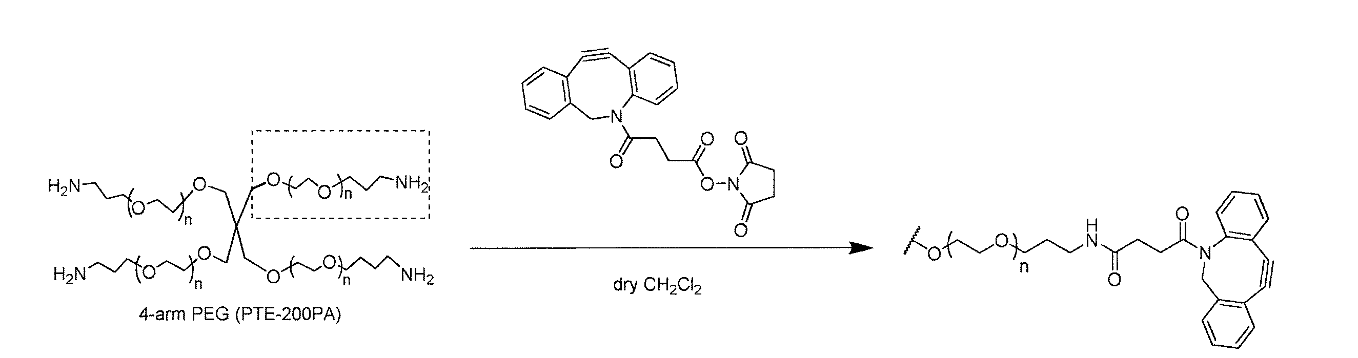 反応は窒素雰囲気下で行った。15 mL二口なすフラスコにPTE-200PAを150 mg(7.5 mmol, 1 eq)、DBCO NHS-esterを21.5 mg(52.5 mmol, 7 eq)入れてドライアップしN2置換してから、dry CH2Cl2 2 mLに溶解させ、室温で18時間撹拌した。原料であるPTE-200PAの消失を確認しジエチルエーテルを20 mLずつ入れた2本の50 mLの遠心チューブに氷浴で反応溶液を入れエーテル沈殿させたところ、白色沈殿が生じた。4 °C、10 krpmで7分間遠心して上澄みをデカンテーションして除き、室温で放置して乾燥させた後さらにデシケーター中で真空乾燥させた。それぞれのチューブに調整した50 mMのTris / HCl (pH = 8.0)のバッファーを3 mLずつ加えてさらにMilliQを2 mLずつ加えて懸濁させた。溶液を4 °C、3 krpmで3分間遠心して、3500分子量分画の透析膜を用いて、MilliQ 2 Lで透析を行った。水交換は、19.5 時間後と22.5 時間後に行った。凍結乾燥を行い、白色固体を得た。収量は130 mg、収率は83%であった。生成物の同定と分子量測定はそれぞれ1H-NMR(CDCl3)とMALDI-TOF-MS(matrix : sinapinic acid)で行った。1H NMR (600 MHz, CDCl3, TMS) δ = 7.68 (d, J = 7.3 Hz, 4H), 7.52 (d, J = 8.2 Hz, 4H), 6.23 (brs, 4H), 5.15 (d, J = 14.1 Hz, 4H), 3.25-4.65 (brm), 3.22 (q, J = 5.9 Hz, 8H), 2.79 (m, 4H), 2.42 (m, 4H), 2.17 (m, 4H), 1.95 (m, 4H)
(細胞含有液の調製)
複数のカルセイン染色Ba/F3細胞を生理食塩水に入れた後、図4に示した2種類のゲル材料(4-アームPEG-PL-アジド及び4-アームPEG-DBCO)を添加し、細胞含有液を得た。尚、細胞密度は50,000,000個/mLで、ゲル材料の濃度はともに、0.9w/v%である。
(マイクロウェルへの細胞固定)
調製した細胞含有液を、図1に示すマイクロ流体デバイスAの導入口A1から当該デバイス(マイクロウェル径=20μm)内に注入した。当該操作を複数回実施した。その後、4℃で5分間インキュベートし、マイクロウェル内へ細胞を沈降させた。その後、フロリナートFC-40(商品名)を導入口A1から当該デバイス内に注入し、マイクロウェル外に余剰に存在するものを排出口A2から排出した。その後、4℃で20分間インキュベートし、マイクロウェル内の細胞含有液をゲル化させた。その結果、図14に示すように、マイクロウェルの64%に細胞が収納されていることが確認できた。
(マイクロウェルに固定された細胞解析)
マイクロウェルに固定されたカルセイン染色Ba/F3細胞にレーザーを照射することにより発せられた蛍光を測定し、細胞の大きさや形状等を解析した。
(マイクロウェルに固定された細胞の除去)
前記細胞解析後、細胞が固定された特定のマイクロウェルに、波長が405nmの光を照射し、当該細胞を包埋していたゲルを分解させた。その後、マイクロ流体デバイスAの導入口A1から生理食塩水を流した。その結果、前記特定のマイクロウェル内に固定された前記細胞を選択的に取得することができた。
<実施例2>
実施例1と同様の手法にて、但し、赤色蛍光色素を修飾した光分解性ハイドロゲルを用いて、カルセイン染色を施したHL60細胞を固定化した。その後、特定の細胞群について光(405nm)を照射し、これらのマイクロウェル内のゲルを溶解させた。その後、液体(生理条件の緩衝液)を流すことで、これら細胞群を選択取得した。ここで、図15aは、マイクロウェル内に光分解性ハイドロゲルで固定化した細胞の画像(緑色蛍光及び赤色蛍光像と明視野像との重ね合わせ画像)であり、四角で囲った部分が光(405nm)を照射したマイクロウェルである。また、図15bは、光照射後、液体(生理条件の緩衝液)で所定回数(本例では15回)洗浄した後の、マイクロウェル内に光分解性ハイドロゲルで固定化した細胞の画像である。図15bから分かるように、当該実施例では、複数(本例では7個)の細胞群を纏めて取得できた。
<実施例3>
実施例1及び2と同様の手法にて、但し、緑色蛍光及び赤色蛍光タンパク質(EGFP及びKusabira-Orange)発現Ba/F3細胞について試験した。図16は、マイクロウェルに固定化された蛍光タンパク質発現Ba/F3細胞の蛍光顕微鏡像である{aは、緑色蛍光像と赤色蛍光像との重ね合わせ画像(低倍率)であり、bは、緑色蛍光及び赤色蛍光像と明視野像の重ね合わせ画像(高倍率)である}。尚、図からは分かり難いが、緑色蛍光のみを発するマイクロウェル、赤色蛍光のみを発するマイクロウェル、赤色蛍光及び緑色蛍光を発するマイクロウェルが存在する。尚、緑色を主に発している細胞から赤色の蛍光も発しているのは、赤色蛍光を発するレーザー光を照射した際に細胞自身から散乱光として発せられた光が検出されたためである。逆に、緑色蛍光を発するレーザー光を照射した際は、EGFP発現の細胞からのみ緑色蛍光がでており、Kusabira-Orange発現の細胞からは緑色蛍光は出ていない。また、わずかではあるが、細胞が二つ入ったマイクロウェルも存在し、蛍光像と明視野像を照らし合わせることでこのようなマイクロウェルを識別できる。
<実施例4>
実施例3にて作製した、マイクロウェルに光分解性ハイドロゲルで固定化された蛍光タンパク質発現Ba/F3細胞に対して、(1段階目)赤色蛍光を有する細胞のみを選択的に取り出し、次いで、(2段階目)緑色蛍光を有する細胞のみを選択的に取り出した。ここで、図17a~dは、マイクロウェル内に光分解性ハイドロゲルで固定化した細胞の画像(緑色蛍光及び赤色蛍光像と明視野像との重ね合わせ画像)である。尚、図からは分かり難いが、緑色蛍光のみを発するマイクロウェル、赤色蛍光のみを発するマイクロウェル、赤色蛍光及び緑色蛍光を発するマイクロウェルが存在する。そして、図17aは、1段階目の赤色蛍光細胞の選択取出し前の画像(四角で囲った部分=赤色蛍光細胞が存在しているウェル)であり、図17bは、1段階目の赤色蛍光細胞の選択取出し後の画像(四角で囲った部分=赤色蛍光細胞が存在していたウェル)である。更に、図17cは、2段階目の緑色蛍光細胞の選択取出し前の画像(四角で囲った部分=緑色蛍光細胞が存在しているウェル)であり、図17dは、2段階目の緑色蛍光細胞の選択取出し後の画像(四角で囲った部分=緑色蛍光細胞が存在していたウェル)である。 <Example 1>
(Synthesis of gel material)
In general, the gel material used in this example was synthesized based on the synthesis scheme of FIG. Hereinafter, a detailed synthesis method of 4-arm PEG-azide and 4-arm PEG-DBCO, which are gel materials used in this example, will be described. The number of repetitions n of the starting 4-arm PEG-amine is about 111.
・ Synthesis of Compound 2
The reaction was performed in the dark. In a 50 mL branch flask, 1.15 g (10.0 mmol, 2 eq) of N-Hydroxysuccinimide (NHS) and 1.99 g (10.0 mmol, 2 eq) of 1-Ethyl-3- (3-dimethylaminopropyl) carbodiimide Hydrochloride (EDC) The mixture was dried up for 20 minutes, purged with nitrogen, and 18 mL of dry DMF was added. After stirring at room temperature to dissolve NHS and EDC, 1.51 g (5.01 mmol, 1 eq) of 4- [4- (1-Hydroxyethyl) -2-methoxy-5-nitrophenoxy] butyric acid (1) was added, Further, 2 mL of dry DMF was added. After stirring at room temperature for 10.5 hours, the completion of the reaction was confirmed, and the solution was concentrated with an evaporator. The concentrated solution was dark yellowish brown, pure water was added, and the precipitated pale yellow solid was collected by suction filtration. A pale yellow solid was obtained after vacuum drying overnight. The yield was 1.97 g, and the yield was 103%. The reason why the yield exceeded 100% is considered that DMF as a solvent could not be completely removed. The product was identified by 1 H-NMR (CDCl 3 ). 1 H NMR (600 MHz, CDCl 3 , TMS) δ = 7.59 (s, 1H), 7.31 (s, 1H), 5.57 (q, J = 5.9 Hz, 1H), 4.18 (t, J = 6.2 Hz, 2H ), 3.99 (s, 3H), 2.90 (t, J = 8.5 Hz, 2H), 2.86 (br s, 4H), 2.29 (quin, J = 6.2 Hz, 2H), 1.56 (d, J = 6.4 Hz, 3H)
Synthesis ofcompound 3
The reaction was conducted in the dark and under an argon atmosphere. In a 50 mL flask, 1.11 g (2.80 mmol, 1 eq) of Compound 2 was added and dried up, and then placed in an argon atmosphere. 10 mL of dry DMF was added, and the mixture was stirred at room temperature. The solution was orange transparent. When 0.700 g (7.00 mmol, 2.5 eq) of 3-azidopropyl-1 -amine was added and reacted at room temperature for 18 hours, the solution was subjected to an evaporator to obtain an orange transparent oil. This was vacuum dried overnight. The mixture was diluted with 100 mL of ethyl acetate and washed three times with pure water. The organic phase was dried over MgSO 4 and filtered, after which the solution was evaporated to give an orange clear oil. Vacuum drying was performed to obtain a brown solid. The yield was 0.97 g and the yield was 91%. The product was identified by 1 H-NMR (CDCl 3 ). 1 H NMR (600 MHz, CDCl 3 , TMS) δ = 7.56 (s, 1H), 7.31 (s, 1H), 5.91 (brs, 1H), 5.56 (q, J = 10.3 Hz, 1H), 4.11 (t , J = 8.8 Hz, 2H), 3.99 (s, 3H), 3.35 (dt, J = 10.3 Hz, 4H), 2.42 (t, J = 10.3 Hz, 2H), 2.20 (quin, J = 8.8 Hz, 2H ), 1.78 (quin, J = 10.3 Hz, 2H), 1.56 (d, J = 10.2 Hz, 3H)
Synthesis ofcompound 4
The reaction was conducted in the dark and under an argon atmosphere. In a 10 mL two-necked flask, 61.7 mg (0.17 mmol, 1 eq) of PL-azide (3) and 112 mg (0.79 mmol, 3.3 eq) of 4-Nitrophenyl Chloroformate were added, dried, and placed in an argon atmosphere. When 2 mL of dry CH 2 Cl 2 was added and stirred, an orange transparent solution was obtained. To this, 110 mL (d = 0.726 g / cm 3 , 0.80 mmol, 4.7 eq) of dry triethylamine was added and stirred for 1.5 hours. As a result, disappearance of compound 3 as a raw material was confirmed. When directly connected to a vacuum pump and triethylamine and CH 2 Cl 2 were distilled off, a yellowish green oil was obtained. Silica gel column chromatography was performed using hexane: ethyl acetate = 1: 1 → ethyl acetate 100%. The column diameter was 2 cm and the column length was 10 cm. The fraction containing the desired product was applied to an evaporator and vacuum-dried to obtain a pale yellow solid. The yield was 46.3 mg, and the yield was 50%. The product was identified by 1 H-NMR (CDCl 3 ) and ESI-MS (pos). 1 H NMR (600 MHz, CDCl 3 , TMS) δ = 8.26 (d, J = 9.1 Hz, 2H), 7.62 (s, 1H), 7.35 (d, J = 9.1 Hz, 2H), 7.12 (s, 1H ), 6.53 (quin, J = 6.4 Hz, 1H), 5.82 (brs, 1H), 4.14 (t, J = 6.2 Hz, 2H), 4.01 (s, 3H), 3.36 (m, 4H), 2.42 (t , J = 7.1 Hz, 2H), 2.21 (quin, J = 6.5 Hz, 2H), 1.79 (m, 5H)
・ Synthesis of 4-arm PEG-azide
The reaction was conducted in the dark and under an argon atmosphere. In a 10 mL two-necked flask, add 152 mg (7.5 mmol, 1 eq) of PTE-200PA (SUNBRIGHT, terminal NH 2 4-branched PEG, Mw to 20000) and 46.3 mg (84.7 mmol, 11 eq) of compound 4 and dry. Up and under an argon atmosphere. After adding 1.5 mL of dry CH 2 Cl 2 and stirring at room temperature for 10.5 hours, disappearance of PTE-200PA as a raw material was confirmed. When the solution was added dropwise to a tube containing 30 mL of diethyl ether on an ice bath, a pale yellow precipitate was formed. The tube was centrifuged (4 ° C, 10 krpm, 10 min), the supernatant was decanted and allowed to stand at room temperature, and then vacuum dried in a desiccator to remove diethyl ether. Add 3 mL of 50 mM Tris-HCl buffer (pH 8.0) and 3 mL of MilliQ, centrifuge the tube (4 ° C, 5000 rpm, 3 min), and add the supernatant to MiiliQ 1.8 L, molecular weight fraction 3500. The dialysis membrane was dialyzed for 3.5 days. The white solid of the desired 4-arm PEG-PL-azide was obtained by lyophilization. The yield was 80 mg and the yield was 49%. Identification and molecular weight measurement of the product were performed by 1 H-NMR (CDCl 3 ) and MALDI-TOF MS (matrix: sinapinic acid), respectively. 1 H NMR (600 MHz, CDCl 3 , TMS) δ = 7.58 (s, 4H), 7.02 (s, 4H), 6.34 (m, 4H), 6.00 (brs, 4H), 5.52 (brs, 4H), 3.25 -4.11 (brm), 2.41 (m, 8H), 2.20 (m, 8H), 1.60-1.88 (brm, 12H + H 2 O)
・ Synthesis of 4-arm PEG-DBCO
The reaction was performed under a nitrogen atmosphere. Add 15 mg (7.5 mmol, 1 eq) of PTE-200PA and 21.5 mg (52.5 mmol, 7 eq) of DBCO NHS-ester to a 15 mL two-necked flask, dry it up, replace with N 2 , and then dry CH 2 Dissolved in 2 mL of Cl 2 and stirred at room temperature for 18 hours. When the disappearance of PTE-200PA as a raw material was confirmed, the reaction solution was put into two 50 mL centrifuge tubes each containing 20 mL of diethyl ether in an ice bath and subjected to ether precipitation. As a result, a white precipitate was formed. After centrifuging at 4 ° C and 10 krpm for 7 minutes, the supernatant was removed by decantation, left to dry at room temperature, and further dried in a desiccator under vacuum. To each tube, 3 mL of 50 mM Tris / HCl (pH = 8.0) buffer prepared and 3 mL of MilliQ were added and suspended. The solution was centrifuged at 3 ° C. for 3 minutes at 4 ° C., and dialyzed against MilliQ 2 L using a dialysis membrane of 3500 molecular weight fraction. Water exchange was performed after 19.5 hours and after 22.5 hours. Lyophilization was performed to obtain a white solid. The yield was 130 mg, and the yield was 83%. The product identification and molecular weight measurement were performed by 1 H-NMR (CDCl 3 ) and MALDI-TOF-MS (matrix: sinapinic acid), respectively. 1 H NMR (600 MHz, CDCl 3 , TMS) δ = 7.68 (d, J = 7.3 Hz, 4H), 7.52 (d, J = 8.2 Hz, 4H), 6.23 (brs, 4H), 5.15 (d, J = 14.1 Hz, 4H), 3.25-4.65 (brm), 3.22 (q, J = 5.9 Hz, 8H), 2.79 (m, 4H), 2.42 (m, 4H), 2.17 (m, 4H), 1.95 (m , 4H)
(Preparation of cell-containing solution)
After placing a plurality of calcein-stained Ba / F3 cells in physiological saline, the two kinds of gel materials (4-arm PEG-PL-azide and 4-arm PEG-DBCO) shown in FIG. A liquid was obtained. The cell density is 50,000,000 cells / mL, and the concentration of the gel material is 0.9 w / v%.
(Cell fixation in microwells)
The prepared cell-containing liquid was injected from the inlet port A 1 of the microfluidic device A to the device (microwell diameter = 20 [mu] m) in shown in FIG. The operation was performed a plurality of times. Then, it incubated at 4 degreeC for 5 minute (s), and the cell was settled in the microwell. Then poured Fluorinert FC-40 (trade name) from the inlet A 1 in the device, was discharged those present in excess to the outside of the micro-well from the outlet A 2. Then, it incubated at 4 degreeC for 20 minute (s), and the cell containing liquid in a microwell was gelatinized. As a result, as shown in FIG. 14, it was confirmed that cells were accommodated in 64% of the microwells.
(Analysis of cells fixed in microwells)
Fluorescence emitted by irradiating a calcein-stained Ba / F3 cell fixed to a microwell with a laser was measured, and the size and shape of the cell were analyzed.
(Removal of cells fixed in microwells)
After the cell analysis, light having a wavelength of 405 nm was irradiated to a specific microwell on which the cell was fixed, and the gel in which the cell was embedded was decomposed. Thereafter, flushed with saline from the inlet A 1 of the microfluidic device A. As a result, the cells fixed in the specific microwell could be selectively obtained.
<Example 2>
HL60 cells subjected to calcein staining were immobilized in the same manner as in Example 1, except that a photodegradable hydrogel modified with a red fluorescent dye was used. Thereafter, light (405 nm) was irradiated to specific cell groups, and the gels in these microwells were dissolved. Thereafter, these cells were selectively obtained by flowing a liquid (buffer solution under physiological conditions). Here, FIG. 15a is an image of a cell immobilized in a microwell with a photodegradable hydrogel (superimposed image of a green fluorescence and a red fluorescence image and a bright field image), and a portion surrounded by a square is light. It is a microwell irradiated with (405 nm). FIG. 15b is an image of cells immobilized with a photodegradable hydrogel in a microwell after being washed a predetermined number of times (in this example, 15 times) with a liquid (buffer solution under physiological conditions) after light irradiation. is there. As can be seen from FIG. 15b, in this example, a plurality (seven cells in this example) of cell groups could be obtained collectively.
<Example 3>
Ba / F3 cells expressing green fluorescent and red fluorescent proteins (EGFP and Kusabila-Orange) were tested in the same manner as in Examples 1 and 2. FIG. 16 is a fluorescence microscopic image of fluorescent protein-expressing Ba / F3 cells immobilized in a microwell {a is a superimposed image (low magnification) of a green fluorescent image and a red fluorescent image, b is Superposed image (high magnification) of green fluorescence and red fluorescence image and bright field image}. Although it is difficult to understand from the figure, there are microwells that emit only green fluorescence, microwells that emit only red fluorescence, and microwells that emit red and green fluorescence. The reason why red fluorescence is emitted from cells mainly emitting green is that light emitted as scattered light from the cells themselves was detected when laser light emitting red fluorescence was irradiated. On the contrary, when the laser beam emitting green fluorescence is irradiated, green fluorescence is emitted only from cells expressing EGFP, and no green fluorescence is emitted from cells expressing Kusabila-Orange. In addition, although there are a few microwells containing two cells, such microwells can be identified by comparing a fluorescent image and a bright field image.
<Example 4>
With respect to the fluorescent protein-expressing Ba / F3 cells prepared in Example 3 and immobilized in a photodegradable hydrogel in a microwell, only the cells having red fluorescence were selectively removed (first stage), and then (2nd stage) Only cells having green fluorescence were selectively removed. Here, FIGS. 17a to 17d are images of cells immobilized with a photodegradable hydrogel in a microwell (superposed images of green fluorescence and red fluorescence images and bright field images). Although it is difficult to understand from the figure, there are microwells that emit only green fluorescence, microwells that emit only red fluorescence, and microwells that emit red and green fluorescence. FIG. 17a is an image before selective extraction of the first-stage red fluorescent cells (a portion surrounded by a square = a well in which red fluorescent cells are present), and FIG. 17b is a first-stage red fluorescent cell. This is an image after selective extraction (portion surrounded by a square = well in which red fluorescent cells were present). Further, FIG. 17c is an image before selective extraction of the second stage green fluorescent cells (portion surrounded by a square = well in which green fluorescent cells are present), and FIG. 17d is the second stage green fluorescent cells. This is an image after selective extraction (portion surrounded by a square = well in which green fluorescent cells were present).
(ゲル材料の合成)
概略、図13の合成スキームに基づき、本実施例で使用するゲル材料を合成した。以下、本実施例で使用するゲル材料である4-アームPEG-アジドと4-アームPEG-DBCOの詳細な合成方法を記載する。尚、原料の4-アームPEG―アミンの繰り返し数nは約111である。
・化合物3の合成
・化合物4の合成
・4-アームPEG-アジドの合成
・4-アームPEG-DBCOの合成
(細胞含有液の調製)
複数のカルセイン染色Ba/F3細胞を生理食塩水に入れた後、図4に示した2種類のゲル材料(4-アームPEG-PL-アジド及び4-アームPEG-DBCO)を添加し、細胞含有液を得た。尚、細胞密度は50,000,000個/mLで、ゲル材料の濃度はともに、0.9w/v%である。
(マイクロウェルへの細胞固定)
調製した細胞含有液を、図1に示すマイクロ流体デバイスAの導入口A1から当該デバイス(マイクロウェル径=20μm)内に注入した。当該操作を複数回実施した。その後、4℃で5分間インキュベートし、マイクロウェル内へ細胞を沈降させた。その後、フロリナートFC-40(商品名)を導入口A1から当該デバイス内に注入し、マイクロウェル外に余剰に存在するものを排出口A2から排出した。その後、4℃で20分間インキュベートし、マイクロウェル内の細胞含有液をゲル化させた。その結果、図14に示すように、マイクロウェルの64%に細胞が収納されていることが確認できた。
(マイクロウェルに固定された細胞解析)
マイクロウェルに固定されたカルセイン染色Ba/F3細胞にレーザーを照射することにより発せられた蛍光を測定し、細胞の大きさや形状等を解析した。
(マイクロウェルに固定された細胞の除去)
前記細胞解析後、細胞が固定された特定のマイクロウェルに、波長が405nmの光を照射し、当該細胞を包埋していたゲルを分解させた。その後、マイクロ流体デバイスAの導入口A1から生理食塩水を流した。その結果、前記特定のマイクロウェル内に固定された前記細胞を選択的に取得することができた。
<実施例2>
実施例1と同様の手法にて、但し、赤色蛍光色素を修飾した光分解性ハイドロゲルを用いて、カルセイン染色を施したHL60細胞を固定化した。その後、特定の細胞群について光(405nm)を照射し、これらのマイクロウェル内のゲルを溶解させた。その後、液体(生理条件の緩衝液)を流すことで、これら細胞群を選択取得した。ここで、図15aは、マイクロウェル内に光分解性ハイドロゲルで固定化した細胞の画像(緑色蛍光及び赤色蛍光像と明視野像との重ね合わせ画像)であり、四角で囲った部分が光(405nm)を照射したマイクロウェルである。また、図15bは、光照射後、液体(生理条件の緩衝液)で所定回数(本例では15回)洗浄した後の、マイクロウェル内に光分解性ハイドロゲルで固定化した細胞の画像である。図15bから分かるように、当該実施例では、複数(本例では7個)の細胞群を纏めて取得できた。
<実施例3>
実施例1及び2と同様の手法にて、但し、緑色蛍光及び赤色蛍光タンパク質(EGFP及びKusabira-Orange)発現Ba/F3細胞について試験した。図16は、マイクロウェルに固定化された蛍光タンパク質発現Ba/F3細胞の蛍光顕微鏡像である{aは、緑色蛍光像と赤色蛍光像との重ね合わせ画像(低倍率)であり、bは、緑色蛍光及び赤色蛍光像と明視野像の重ね合わせ画像(高倍率)である}。尚、図からは分かり難いが、緑色蛍光のみを発するマイクロウェル、赤色蛍光のみを発するマイクロウェル、赤色蛍光及び緑色蛍光を発するマイクロウェルが存在する。尚、緑色を主に発している細胞から赤色の蛍光も発しているのは、赤色蛍光を発するレーザー光を照射した際に細胞自身から散乱光として発せられた光が検出されたためである。逆に、緑色蛍光を発するレーザー光を照射した際は、EGFP発現の細胞からのみ緑色蛍光がでており、Kusabira-Orange発現の細胞からは緑色蛍光は出ていない。また、わずかではあるが、細胞が二つ入ったマイクロウェルも存在し、蛍光像と明視野像を照らし合わせることでこのようなマイクロウェルを識別できる。
<実施例4>
実施例3にて作製した、マイクロウェルに光分解性ハイドロゲルで固定化された蛍光タンパク質発現Ba/F3細胞に対して、(1段階目)赤色蛍光を有する細胞のみを選択的に取り出し、次いで、(2段階目)緑色蛍光を有する細胞のみを選択的に取り出した。ここで、図17a~dは、マイクロウェル内に光分解性ハイドロゲルで固定化した細胞の画像(緑色蛍光及び赤色蛍光像と明視野像との重ね合わせ画像)である。尚、図からは分かり難いが、緑色蛍光のみを発するマイクロウェル、赤色蛍光のみを発するマイクロウェル、赤色蛍光及び緑色蛍光を発するマイクロウェルが存在する。そして、図17aは、1段階目の赤色蛍光細胞の選択取出し前の画像(四角で囲った部分=赤色蛍光細胞が存在しているウェル)であり、図17bは、1段階目の赤色蛍光細胞の選択取出し後の画像(四角で囲った部分=赤色蛍光細胞が存在していたウェル)である。更に、図17cは、2段階目の緑色蛍光細胞の選択取出し前の画像(四角で囲った部分=緑色蛍光細胞が存在しているウェル)であり、図17dは、2段階目の緑色蛍光細胞の選択取出し後の画像(四角で囲った部分=緑色蛍光細胞が存在していたウェル)である。 <Example 1>
(Synthesis of gel material)
In general, the gel material used in this example was synthesized based on the synthesis scheme of FIG. Hereinafter, a detailed synthesis method of 4-arm PEG-azide and 4-arm PEG-DBCO, which are gel materials used in this example, will be described. The number of repetitions n of the starting 4-arm PEG-amine is about 111.
Synthesis of
Synthesis of
・ Synthesis of 4-arm PEG-azide
・ Synthesis of 4-arm PEG-DBCO
(Preparation of cell-containing solution)
After placing a plurality of calcein-stained Ba / F3 cells in physiological saline, the two kinds of gel materials (4-arm PEG-PL-azide and 4-arm PEG-DBCO) shown in FIG. A liquid was obtained. The cell density is 50,000,000 cells / mL, and the concentration of the gel material is 0.9 w / v%.
(Cell fixation in microwells)
The prepared cell-containing liquid was injected from the inlet port A 1 of the microfluidic device A to the device (microwell diameter = 20 [mu] m) in shown in FIG. The operation was performed a plurality of times. Then, it incubated at 4 degreeC for 5 minute (s), and the cell was settled in the microwell. Then poured Fluorinert FC-40 (trade name) from the inlet A 1 in the device, was discharged those present in excess to the outside of the micro-well from the outlet A 2. Then, it incubated at 4 degreeC for 20 minute (s), and the cell containing liquid in a microwell was gelatinized. As a result, as shown in FIG. 14, it was confirmed that cells were accommodated in 64% of the microwells.
(Analysis of cells fixed in microwells)
Fluorescence emitted by irradiating a calcein-stained Ba / F3 cell fixed to a microwell with a laser was measured, and the size and shape of the cell were analyzed.
(Removal of cells fixed in microwells)
After the cell analysis, light having a wavelength of 405 nm was irradiated to a specific microwell on which the cell was fixed, and the gel in which the cell was embedded was decomposed. Thereafter, flushed with saline from the inlet A 1 of the microfluidic device A. As a result, the cells fixed in the specific microwell could be selectively obtained.
<Example 2>
HL60 cells subjected to calcein staining were immobilized in the same manner as in Example 1, except that a photodegradable hydrogel modified with a red fluorescent dye was used. Thereafter, light (405 nm) was irradiated to specific cell groups, and the gels in these microwells were dissolved. Thereafter, these cells were selectively obtained by flowing a liquid (buffer solution under physiological conditions). Here, FIG. 15a is an image of a cell immobilized in a microwell with a photodegradable hydrogel (superimposed image of a green fluorescence and a red fluorescence image and a bright field image), and a portion surrounded by a square is light. It is a microwell irradiated with (405 nm). FIG. 15b is an image of cells immobilized with a photodegradable hydrogel in a microwell after being washed a predetermined number of times (in this example, 15 times) with a liquid (buffer solution under physiological conditions) after light irradiation. is there. As can be seen from FIG. 15b, in this example, a plurality (seven cells in this example) of cell groups could be obtained collectively.
<Example 3>
Ba / F3 cells expressing green fluorescent and red fluorescent proteins (EGFP and Kusabila-Orange) were tested in the same manner as in Examples 1 and 2. FIG. 16 is a fluorescence microscopic image of fluorescent protein-expressing Ba / F3 cells immobilized in a microwell {a is a superimposed image (low magnification) of a green fluorescent image and a red fluorescent image, b is Superposed image (high magnification) of green fluorescence and red fluorescence image and bright field image}. Although it is difficult to understand from the figure, there are microwells that emit only green fluorescence, microwells that emit only red fluorescence, and microwells that emit red and green fluorescence. The reason why red fluorescence is emitted from cells mainly emitting green is that light emitted as scattered light from the cells themselves was detected when laser light emitting red fluorescence was irradiated. On the contrary, when the laser beam emitting green fluorescence is irradiated, green fluorescence is emitted only from cells expressing EGFP, and no green fluorescence is emitted from cells expressing Kusabila-Orange. In addition, although there are a few microwells containing two cells, such microwells can be identified by comparing a fluorescent image and a bright field image.
<Example 4>
With respect to the fluorescent protein-expressing Ba / F3 cells prepared in Example 3 and immobilized in a photodegradable hydrogel in a microwell, only the cells having red fluorescence were selectively removed (first stage), and then (2nd stage) Only cells having green fluorescence were selectively removed. Here, FIGS. 17a to 17d are images of cells immobilized with a photodegradable hydrogel in a microwell (superposed images of green fluorescence and red fluorescence images and bright field images). Although it is difficult to understand from the figure, there are microwells that emit only green fluorescence, microwells that emit only red fluorescence, and microwells that emit red and green fluorescence. FIG. 17a is an image before selective extraction of the first-stage red fluorescent cells (a portion surrounded by a square = a well in which red fluorescent cells are present), and FIG. 17b is a first-stage red fluorescent cell. This is an image after selective extraction (portion surrounded by a square = well in which red fluorescent cells were present). Further, FIG. 17c is an image before selective extraction of the second stage green fluorescent cells (portion surrounded by a square = well in which green fluorescent cells are present), and FIG. 17d is the second stage green fluorescent cells. This is an image after selective extraction (portion surrounded by a square = well in which green fluorescent cells were present).
Claims (14)
- 複数のマイクロウェルを有する流路と、
複数の被検体を含有する液を、前記流路に導入可能な導入路と、
前記複数のマイクロウェルに収納された複数の被検体から情報を取得する情報取得部と、
前記情報取得部が取得した情報に基づき、一のマイクロウェル内の被検体を当該マイクロウェル内から選択的に取り出し可能な選択取り出し手段と、
前記選択取り出し手段により選択的に取り出された被検体を回収可能な被検体回収部と
を有するセルソーター又はフローサイトメーターであって、
前記複数のマイクロウェルが、被検体及び分解性ゲルを収納可能であり、
前記選択取り出し手段が、取り出されるべき被検体が保持されたマイクロウェル内の分解性ゲルに対し、当該分解性ゲルが分解する処理を施す分解処理部である
よう構成されたセルソーター又はフローサイトメーター。 A flow path having a plurality of microwells;
An introduction path capable of introducing a liquid containing a plurality of analytes into the flow path;
An information acquisition unit for acquiring information from a plurality of subjects stored in the plurality of microwells;
Based on the information acquired by the information acquisition unit, a selective extraction means capable of selectively extracting a subject in one microwell from the microwell;
A cell sorter or a flow cytometer having a specimen collecting section capable of collecting a specimen selectively taken out by the selective taking-out means,
The plurality of microwells can store the analyte and the degradable gel,
A cell sorter or flow cytometer configured such that the selective extraction means is a decomposition processing unit that performs a process of decomposing the degradable gel in the microwell in which the specimen to be extracted is held. - 前記流路が平面状であり、前記複数のマイクロウェルは、当該流路を構成する下壁に設けられている、請求項1記載のセルソーター又はフローサイトメーター。 The cell sorter or flow cytometer according to claim 1, wherein the flow path is planar, and the plurality of microwells are provided on a lower wall constituting the flow path.
- 前記分解性ゲルが、光分解性ゲルであり、
前記分解処理部は、前記光分解性ゲルが分解する波長の光を照射可能な光照射部である、請求項1又は2記載のセルソーター又はフローサイトメーター。 The degradable gel is a photodegradable gel;
The cell sorter or flow cytometer according to claim 1 or 2, wherein the decomposition processing unit is a light irradiation unit capable of irradiating light having a wavelength at which the photodegradable gel is decomposed. - 前記情報取得部は、
前記複数のマイクロウェルからの前記情報を、マイクロウェル毎に取得、複数のマイクロウェルのうちの2以上のものについて一度に取得、又は前記複数すべてのマイクロウェルについて一度に取得可能である、請求項1~3のいずれか一項記載のセルソーター又はフローサイトメーター。 The information acquisition unit
The information from the plurality of microwells can be acquired for each microwell, acquired at one time for two or more of the plurality of microwells, or acquired at once for all the plurality of microwells. The cell sorter or flow cytometer according to any one of claims 1 to 3. - 前記情報取得部は、
前記複数のマイクロウェルに対して、取得されるべき前記情報のソースとなる情報ソース波を照射可能な情報ソース波照射部と、
前記情報ソース波照射部が前記複数のマイクロウェルに対して前記情報ソース波を照射した際、前記複数のマイクロウェルから発生し得る前記情報を受信する情報受信部と
を有する、請求項1~4のいずれか一項記載のセルソーター又はフローサイトメーター。 The information acquisition unit
An information source wave irradiation unit capable of irradiating the plurality of microwells with an information source wave serving as a source of the information to be acquired;
5. An information receiving unit that receives the information that can be generated from the plurality of microwells when the information source wave irradiation unit irradiates the information source waves to the plurality of microwells. The cell sorter or flow cytometer according to any one of the above. - 前記情報ソース波照射部は、第一態様として、マイクロウェル毎に前記情報ソース波を照射可能であるか;第二態様として、複数のマイクロウェルのうちの2以上のものを一度に照射可能であるか;又は、第三態様として、前記複数すべてのマイクロウェルを一度に照射可能であり;前記第一態様及び前記第二態様の場合には、前記複数のマイクロウェルすべてを走査して照射し得る、請求項5記載のセルソーター又はフローサイトメーター。 The information source wave irradiation unit can irradiate the information source wave for each microwell as the first aspect; as the second aspect, it can irradiate two or more of the plurality of microwells at a time. Or, as a third embodiment, all of the plurality of microwells can be irradiated at once; in the case of the first embodiment and the second embodiment, all of the plurality of microwells are scanned and irradiated. The cell sorter or flow cytometer according to claim 5 obtained.
- 前記情報ソース波照射部は、解析項目の数に応じ、複数種の情報ソース波を出力可能である、請求項5又は6項記載のセルソーター又はフローサイトメーター。 The cell sorter or flow cytometer according to claim 5 or 6, wherein the information source wave irradiation unit is capable of outputting a plurality of types of information source waves according to the number of analysis items.
- 前記情報ソース波照射部から照射される前記情報ソース波が光であり、前記分解性ゲルが光分解性ゲルであり、且つ、前記分解処理部が、前記光分解性ゲルが分解する波長の光を照射可能な光照射部である場合、当該光の波長は、前記光分解性ゲルが分解する光の波長とは異なる、請求項5~7のいずれか一項記載のセルソーター又はフローサイトメーター。 The information source wave irradiated from the information source wave irradiation unit is light, the degradable gel is a photodegradable gel, and the decomposition processing unit is light having a wavelength at which the photodegradable gel is decomposed. The cell sorter or flow cytometer according to any one of claims 5 to 7, wherein when the light irradiation unit is capable of irradiating, the wavelength of the light is different from the wavelength of the light decomposed by the photodegradable gel.
- 前記光照射部と前記情報ソース波照射部とが、同一光源であり、
前記同一光源は、前記光分解性ゲルが分解する波長の光と、取得されるべき前記情報のソースとなる、前記光分解ゲルが分解する前記波長とは異なる波長の光と、を切替照射可能に構成されている、請求項8記載のセルソーター又はフローサイトメーター。 The light irradiation unit and the information source wave irradiation unit are the same light source,
The same light source can switch and irradiate light having a wavelength at which the photodegradable gel decomposes and light having a wavelength different from the wavelength at which the photolytic gel is decomposed, which is a source of the information to be acquired. The cell sorter or flow cytometer according to claim 8, which is configured as follows. - 前記セルソーター又はフローサイトメーターは、
前記情報取得部で取得した前記情報を自動解析する自動解析手段を有していてもよく、
更に、ユーザーの指示又は前記自動解析手段による解析結果に基づき、取得が望まれる被検体が収納されたマイクロウェル内の分解性ゲルに当該ゲルが分解する処理を施すよう、前記選択取り出し手段を制御する選択取り出し制御手段
を更に有する、請求項1~9のいずれか一項記載のセルソーター又はフローサイトメーター。 The cell sorter or flow cytometer is
It may have an automatic analysis means for automatically analyzing the information acquired by the information acquisition unit,
Furthermore, based on the user's instruction or the analysis result by the automatic analysis means, the selective extraction means is controlled so that the degradable gel in the microwell containing the specimen to be obtained is subjected to a process for degrading the gel. The cell sorter or flow cytometer according to any one of claims 1 to 9, further comprising a selective take-out control means. - 請求項1~10のいずれか一項記載のセルソーター又はフローサイトメーター用である、前記流路を備えたマイクロ流体デバイス。 A microfluidic device comprising the flow path, which is for the cell sorter or flow cytometer according to any one of claims 1 to 10.
- 請求項1~10のいずれか一項記載のセルソーター又はフローサイトメーター用である、前記分解性ゲルを形成し得る材料を含有する液体。 A liquid containing a material capable of forming the degradable gel, which is for the cell sorter or flow cytometer according to any one of claims 1 to 10.
- 複数のマイクロウェルを有する流路に、被検体を含有する液を流し、前記マイクロウェル内に前記被検体を充填する充填工程と、
前記充填工程後、前記マイクロウェル内に充填された前記被検体を解析する解析工程と、
前記解析工程後、前記被検体を取り出す取得工程と
を含む被検体回収方法であって、
前記液が、第一成分と、前記第一成分とは異なる第二成分と、を含有し、
前記第一成分が、基本骨格が生体適合性ポリマーであり且つ前記第二成分と結合し得る第一部を有し、
前記第二成分が、基本骨格が生体適合性ポリマーであり且つ前記第一成分と結合し得る第二部を有し、
前記解析工程の際には、前記第一部と前記第二部との結合形成により、前記第一成分と前記第二成分とが架橋したゲルが、前記マイクロウェル内に形成された状態にあり、
前記第一成分及び/又は前記第二成分は、分解性部分を更に有しており、
前記取得工程においては、分解処理を行うことで、前記分解性部分を分解させて前記ゲルを分解し、前記被検体を取り出す、被検体回収方法。 A filling step of flowing a liquid containing a specimen into a flow path having a plurality of microwells, and filling the specimen into the microwell;
After the filling step, an analysis step for analyzing the specimen filled in the microwell;
After the analysis step, an object recovery method including an acquisition step of taking out the subject,
The liquid contains a first component and a second component different from the first component,
The first component has a first portion in which the basic skeleton is a biocompatible polymer and can be bonded to the second component;
The second component has a second part in which the basic skeleton is a biocompatible polymer and can bind to the first component;
In the analysis step, a gel in which the first component and the second component are cross-linked is formed in the microwell by the bond formation between the first part and the second part. ,
The first component and / or the second component further has a degradable portion,
In the acquisition step, a subject recovery method in which, by performing a decomposition process, the degradable portion is decomposed to decompose the gel, and the sample is taken out. - 前記第一部がアジドであり、前記第二部がアルキンである、請求項13記載の被検体回収方法。 14. The specimen recovery method according to claim 13, wherein the first part is an azide and the second part is an alkyne.
Applications Claiming Priority (2)
| Application Number | Priority Date | Filing Date | Title |
|---|---|---|---|
| JP2016-061233 | 2016-03-25 | ||
| JP2016061233A JP2019090610A (en) | 2016-03-25 | 2016-03-25 | Cell sorting method, and flow cytometry and cell sorter using the same |
Publications (1)
| Publication Number | Publication Date |
|---|---|
| WO2017163463A1 true WO2017163463A1 (en) | 2017-09-28 |
Family
ID=59900135
Family Applications (1)
| Application Number | Title | Priority Date | Filing Date |
|---|---|---|---|
| PCT/JP2016/077645 WO2017163463A1 (en) | 2016-03-25 | 2016-09-20 | Cell sorting method and flow cytometry and cell sorter using same |
Country Status (2)
| Country | Link |
|---|---|
| JP (1) | JP2019090610A (en) |
| WO (1) | WO2017163463A1 (en) |
Citations (3)
| Publication number | Priority date | Publication date | Assignee | Title |
|---|---|---|---|---|
| WO2012165462A1 (en) * | 2011-05-31 | 2012-12-06 | 国立大学法人 東京大学 | Hydrogel and method for producing same |
| WO2014188911A1 (en) * | 2013-05-22 | 2014-11-27 | 独立行政法人産業技術総合研究所 | Photodegradable crosslinking agent, photodegradable gel, cell culture device, cell arrangement/separation device, cell arrangement method, cell separation method, method of forming tissue material, and tissue material |
| WO2016159380A1 (en) * | 2015-04-03 | 2016-10-06 | 国立研究開発法人産業技術総合研究所 | Photodegradable hydrogel, culture device, method for forming tissue, and method for separating cells |
-
2016
- 2016-03-25 JP JP2016061233A patent/JP2019090610A/en active Pending
- 2016-09-20 WO PCT/JP2016/077645 patent/WO2017163463A1/en active Application Filing
Patent Citations (3)
| Publication number | Priority date | Publication date | Assignee | Title |
|---|---|---|---|---|
| WO2012165462A1 (en) * | 2011-05-31 | 2012-12-06 | 国立大学法人 東京大学 | Hydrogel and method for producing same |
| WO2014188911A1 (en) * | 2013-05-22 | 2014-11-27 | 独立行政法人産業技術総合研究所 | Photodegradable crosslinking agent, photodegradable gel, cell culture device, cell arrangement/separation device, cell arrangement method, cell separation method, method of forming tissue material, and tissue material |
| WO2016159380A1 (en) * | 2015-04-03 | 2016-10-06 | 国立研究開発法人産業技術総合研究所 | Photodegradable hydrogel, culture device, method for forming tissue, and method for separating cells |
Non-Patent Citations (4)
| Title |
|---|
| GIULBUDAGIAN M. ET AL.: "Fabrication of thermoresponsive nanogels by thermo-nanoprecipitation and in situ encapsulation of bioactives", POLYMER CHEMISTRY, vol. 5, 2014, pages 6909 - 6913, XP055316696, DOI: doi:10.1039/C4PY01186D * |
| KOVAC, J. R. ET AL.: "Intuitive, Image-Based Cell Sorting Using Optofluidic Cell Sorting", ANALYTICAL CHEMISTRY, vol. 79, 2007, pages 9321 - 9330, XP055179441, DOI: doi:10.1021/ac071366y * |
| RISA TAKAGI: "Photo-responsive microgel arrays for single-cell sorting", THE 96TH ANNUAL MEETING OF THE CHEMICAL SOCIETY OF JAPAN PROGRAM, 10 March 2016 (2016-03-10) * |
| SUN, T. ET AL.: "Image-Based Single- Cell Sorting via Dual-Photopolymerized Microwell Arrays", ANALYTICAL CHEMISTRY, vol. 86, 2014, pages 977 - 981, XP055549230, DOI: doi:10.1021/ac403777g * |
Also Published As
| Publication number | Publication date |
|---|---|
| JP2019090610A (en) | 2019-06-13 |
Similar Documents
| Publication | Publication Date | Title |
|---|---|---|
| McKinnon | Flow cytometry: an overview | |
| JP7075126B2 (en) | Image-based cell sorting system and method | |
| JP6657721B2 (en) | Cell analysis method, cell analysis chip, cell analysis reagent, cell analysis kit, and cell analysis device | |
| JP5087192B2 (en) | Method and apparatus for selectively aiming a specific cell in a cell group | |
| JP5320510B2 (en) | Cell analyzer | |
| AU2002232892B2 (en) | Method and device for selectively targeting cells within a three -dimensional specimen | |
| CN108761054B (en) | Measurement of immune cell immune stimulation responsiveness, determination of immune cell immune synapse formation ability, and cell analyzer | |
| JP2005503170A (en) | Opt-injection method | |
| WO2021033750A1 (en) | Cell analyzer system and cell analysis method | |
| JP2005515071A (en) | Method and apparatus for generating and utilizing a moving linear light gradient | |
| JP6965874B2 (en) | Cell culture method | |
| US20210164883A1 (en) | Cell analysis method, cell analysis device, and cell analysis system | |
| CN112881267A (en) | Cell analysis method, device, system, and program, and method, device, and program for generating artificial intelligence algorithm for training | |
| CN110192140A (en) | System and method for recycling fluorescence imaging | |
| JP2024016251A (en) | Microparticle recovery method, microchip for microparticle separation, microparticle recovery device, emulsion manufacturing method, and emulsion | |
| WO2017163463A1 (en) | Cell sorting method and flow cytometry and cell sorter using same | |
| JP6582486B2 (en) | Method for detecting rare cells in blood | |
| JP4630015B2 (en) | Cell separation and recovery method, cell separation chip and cell separation apparatus | |
| EP3916393B1 (en) | Method for detection of cells by repetitive staining and destaining | |
| US20230390772A1 (en) | Microfluidic determination of heterogeneous objects | |
| WO2022181049A1 (en) | Cell processing system, cell processing method, and learning data creation method | |
| Togo et al. | Quantitative evaluation of the impact of artificial cell adhesion via DNA hybridization on E-cadherin-mediated cell adhesion | |
| EP3489684A1 (en) | Method for photobleaching stained cells | |
| WO2023189281A1 (en) | Information processing apparatus, information processing method, cell culturing system, and program | |
| CN108884486A (en) | Cell detection method |
Legal Events
| Date | Code | Title | Description |
|---|---|---|---|
| NENP | Non-entry into the national phase |
Ref country code: DE |
|
| 121 | Ep: the epo has been informed by wipo that ep was designated in this application |
Ref document number: 16895486 Country of ref document: EP Kind code of ref document: A1 |
|
| 122 | Ep: pct application non-entry in european phase |
Ref document number: 16895486 Country of ref document: EP Kind code of ref document: A1 |
|
| NENP | Non-entry into the national phase |
Ref country code: JP |