WO2017163407A1 - Endoscope device, endoscope system, and surgery system provided with same - Google Patents
Endoscope device, endoscope system, and surgery system provided with same Download PDFInfo
- Publication number
- WO2017163407A1 WO2017163407A1 PCT/JP2016/059672 JP2016059672W WO2017163407A1 WO 2017163407 A1 WO2017163407 A1 WO 2017163407A1 JP 2016059672 W JP2016059672 W JP 2016059672W WO 2017163407 A1 WO2017163407 A1 WO 2017163407A1
- Authority
- WO
- WIPO (PCT)
- Prior art keywords
- endoscope
- image
- endoscopes
- imaging device
- rotation
- Prior art date
Links
Images


Classifications
-
- A—HUMAN NECESSITIES
- A61—MEDICAL OR VETERINARY SCIENCE; HYGIENE
- A61B—DIAGNOSIS; SURGERY; IDENTIFICATION
- A61B1/00—Instruments for performing medical examinations of the interior of cavities or tubes of the body by visual or photographical inspection, e.g. endoscopes; Illuminating arrangements therefor
- A61B1/00147—Holding or positioning arrangements
- A61B1/00149—Holding or positioning arrangements using articulated arms
-
- A—HUMAN NECESSITIES
- A61—MEDICAL OR VETERINARY SCIENCE; HYGIENE
- A61B—DIAGNOSIS; SURGERY; IDENTIFICATION
- A61B1/00—Instruments for performing medical examinations of the interior of cavities or tubes of the body by visual or photographical inspection, e.g. endoscopes; Illuminating arrangements therefor
- A61B1/00002—Operational features of endoscopes
- A61B1/00004—Operational features of endoscopes characterised by electronic signal processing
- A61B1/00009—Operational features of endoscopes characterised by electronic signal processing of image signals during a use of endoscope
- A61B1/000094—Operational features of endoscopes characterised by electronic signal processing of image signals during a use of endoscope extracting biological structures
-
- A—HUMAN NECESSITIES
- A61—MEDICAL OR VETERINARY SCIENCE; HYGIENE
- A61B—DIAGNOSIS; SURGERY; IDENTIFICATION
- A61B1/00—Instruments for performing medical examinations of the interior of cavities or tubes of the body by visual or photographical inspection, e.g. endoscopes; Illuminating arrangements therefor
- A61B1/04—Instruments for performing medical examinations of the interior of cavities or tubes of the body by visual or photographical inspection, e.g. endoscopes; Illuminating arrangements therefor combined with photographic or television appliances
- A61B1/05—Instruments for performing medical examinations of the interior of cavities or tubes of the body by visual or photographical inspection, e.g. endoscopes; Illuminating arrangements therefor combined with photographic or television appliances characterised by the image sensor, e.g. camera, being in the distal end portion
-
- A—HUMAN NECESSITIES
- A61—MEDICAL OR VETERINARY SCIENCE; HYGIENE
- A61B—DIAGNOSIS; SURGERY; IDENTIFICATION
- A61B34/00—Computer-aided surgery; Manipulators or robots specially adapted for use in surgery
- A61B34/25—User interfaces for surgical systems
-
- A—HUMAN NECESSITIES
- A61—MEDICAL OR VETERINARY SCIENCE; HYGIENE
- A61B—DIAGNOSIS; SURGERY; IDENTIFICATION
- A61B34/00—Computer-aided surgery; Manipulators or robots specially adapted for use in surgery
- A61B34/30—Surgical robots
-
- A—HUMAN NECESSITIES
- A61—MEDICAL OR VETERINARY SCIENCE; HYGIENE
- A61B—DIAGNOSIS; SURGERY; IDENTIFICATION
- A61B90/00—Instruments, implements or accessories specially adapted for surgery or diagnosis and not covered by any of the groups A61B1/00 - A61B50/00, e.g. for luxation treatment or for protecting wound edges
- A61B90/36—Image-producing devices or illumination devices not otherwise provided for
- A61B90/361—Image-producing devices, e.g. surgical cameras
-
- A—HUMAN NECESSITIES
- A61—MEDICAL OR VETERINARY SCIENCE; HYGIENE
- A61B—DIAGNOSIS; SURGERY; IDENTIFICATION
- A61B90/00—Instruments, implements or accessories specially adapted for surgery or diagnosis and not covered by any of the groups A61B1/00 - A61B50/00, e.g. for luxation treatment or for protecting wound edges
- A61B90/50—Supports for surgical instruments, e.g. articulated arms
-
- A—HUMAN NECESSITIES
- A61—MEDICAL OR VETERINARY SCIENCE; HYGIENE
- A61B—DIAGNOSIS; SURGERY; IDENTIFICATION
- A61B1/00—Instruments for performing medical examinations of the interior of cavities or tubes of the body by visual or photographical inspection, e.g. endoscopes; Illuminating arrangements therefor
- A61B1/313—Instruments for performing medical examinations of the interior of cavities or tubes of the body by visual or photographical inspection, e.g. endoscopes; Illuminating arrangements therefor for introducing through surgical openings, e.g. laparoscopes
-
- A—HUMAN NECESSITIES
- A61—MEDICAL OR VETERINARY SCIENCE; HYGIENE
- A61B—DIAGNOSIS; SURGERY; IDENTIFICATION
- A61B34/00—Computer-aided surgery; Manipulators or robots specially adapted for use in surgery
- A61B34/30—Surgical robots
- A61B2034/301—Surgical robots for introducing or steering flexible instruments inserted into the body, e.g. catheters or endoscopes
-
- A—HUMAN NECESSITIES
- A61—MEDICAL OR VETERINARY SCIENCE; HYGIENE
- A61B—DIAGNOSIS; SURGERY; IDENTIFICATION
- A61B34/00—Computer-aided surgery; Manipulators or robots specially adapted for use in surgery
- A61B34/30—Surgical robots
- A61B2034/302—Surgical robots specifically adapted for manipulations within body cavities, e.g. within abdominal or thoracic cavities
-
- A—HUMAN NECESSITIES
- A61—MEDICAL OR VETERINARY SCIENCE; HYGIENE
- A61B—DIAGNOSIS; SURGERY; IDENTIFICATION
- A61B34/00—Computer-aided surgery; Manipulators or robots specially adapted for use in surgery
- A61B34/30—Surgical robots
- A61B2034/305—Details of wrist mechanisms at distal ends of robotic arms
-
- A—HUMAN NECESSITIES
- A61—MEDICAL OR VETERINARY SCIENCE; HYGIENE
- A61B—DIAGNOSIS; SURGERY; IDENTIFICATION
- A61B90/00—Instruments, implements or accessories specially adapted for surgery or diagnosis and not covered by any of the groups A61B1/00 - A61B50/00, e.g. for luxation treatment or for protecting wound edges
- A61B90/36—Image-producing devices or illumination devices not otherwise provided for
- A61B2090/364—Correlation of different images or relation of image positions in respect to the body
-
- A—HUMAN NECESSITIES
- A61—MEDICAL OR VETERINARY SCIENCE; HYGIENE
- A61B—DIAGNOSIS; SURGERY; IDENTIFICATION
- A61B34/00—Computer-aided surgery; Manipulators or robots specially adapted for use in surgery
- A61B34/70—Manipulators specially adapted for use in surgery
Definitions
- the present disclosure relates to an endoscope apparatus and a surgical system including the endoscope apparatus.
- MIS minimally invasive surgery
- the surgical site often includes a body cavity such as the patient's abdomen.
- the body cavity is optionally expanded using a clear fluid such as insufflation gas.
- a surgeon such as a doctor uses an end effector of an elongated surgical instrument, operates a handle of the surgical instrument, and manipulates tissue while viewing the surgical site on a video monitor.
- Laparoscopy is a type of endoscopy for performing minimally invasive examinations and surgery within the abdominal cavity.
- the cannula sleeve is passed through a small (typically 1/2 inch or less) incision and an inlet port for the laparoscopic surgical instrument is set.
- gas is blown into the abdomen of the patient to form a constant volume space in the abdominal cavity.
- the laparoscopic surgical instrument includes a laparoscope (a type of endoscope applied to view the surgical field in the abdominal cavity) and a work tool.
- the working tool is similar to that used in conventional open surgery except that the working end or end effector of each tool is separated from its handle by a tool shaft.
- Patent Document 1 supports a robot manipulator such as a manipulator for moving a surgical instrument, a laparoscope, and a desired surgical site in a patient's body.
- a robot manipulator such as a manipulator for moving a surgical instrument, a laparoscope, and a desired surgical site in a patient's body.
- a minimally invasive robotic surgical system is disclosed that aligns with
- the endoscope apparatus includes an imaging device at the distal end portion of a cylindrical housing (not limited to a cylindrical shape), and acquires an image in the body of a subject. And three or more endoscopes, and a control device that is electrically connected to the three or more endoscopes and processes an image acquired by each of the three or more endoscopes.
- the control apparatus connects the images using the position information of the imaging devices of the three or more endoscopes and the feature points of the images acquired by the imaging devices to generate a composite image.
- An endoscope apparatus includes an imaging device provided with an imaging device at a distal end portion of a cylindrical housing, and an endoscope tube for acquiring an intra-abdominal image of a subject, and an endoscope tube
- a rotation drive control unit that rotates at least a tip portion of the casing, and a control device that is electrically connected to the endoscope and processes an image acquired by the endoscope.
- the optical axis of the imaging device forms a predetermined angle with the rotation axis of the tip portion of the cylindrical housing.
- the control device generates a composite image by joining the images acquired by the imaging device while rotating the distal end portion of the cylindrical casing of the endoscope.
- the endoscope system operates a robot cart including an endoscope apparatus and a surgical arm to which a surgical instrument is attached, and operates the endoscope and the surgical arm of the robot cart. And a display device that displays an image captured by the endoscope device on a display screen.
- Each of the endoscope apparatuses includes an imaging device at a distal end portion of a cylindrical casing, and electrically connects three or more endoscopes and three or more endoscopes that acquire an image of the inside of a subject.
- a control device that processes images acquired by each of the three or more endoscopes. The control apparatus generates a composite image by connecting the images using the feature points of the images acquired by the imaging devices.
- FIG. 1 Another aspect of the endoscope system according to the present embodiment is a robot cart including an endoscope apparatus and a surgical arm to which a surgical instrument is attached, and the endoscope and the surgical arm of the robot cart.
- a console device that transmits an instruction for operating the device, and a display device that displays an image captured by the endoscope device on a display screen.
- An endoscope apparatus includes an imaging device at a distal end portion of a cylindrical housing, and rotates to rotate at least a distal end portion of an endoscope that acquires an in-vivo image of a subject and an endoscope. And a controller that is electrically connected to the endoscope and that processes an image acquired by the endoscope.
- the optical axis of the imaging device forms a predetermined angle with the rotation axis of the tip portion of the cylindrical housing.
- the control device generates a composite image by joining the images acquired by the imaging device while rotating the distal end portion of the cylindrical casing of the endoscope.
- FIG. 1 is a diagram illustrating a schematic configuration example of a surgical system (also referred to as a surgical robot system) 1 according to an embodiment. It is a figure which shows the internal structural example of the patient side cart 20 by 1st Embodiment. It is a flowchart for demonstrating the synthetic
- the embodiment of the present disclosure may be implemented by software running on a general-purpose computer, or may be implemented by dedicated hardware or a combination of software and hardware.
- each processing unit as a program (for example, an image processing unit, etc.)” as a subject (operation subject).
- the program is a processor (CPU or the like: simply a control device). Since the processing determined by being executed by the processing is performed using the memory and the communication port (communication control device), the description may be made with the processor as the subject.
- a patient-side cart (also referred to as a surgical robot) including an endoscope apparatus including three or more endoscope arms and a patient-side cart are operated. And a console device.
- a composite image is generated by connecting the images using the feature points of the images acquired by the imaging devices of three or more endoscopes, and the composite image is displayed on the display screen. Is displayed. Since a composite image is generated from images of three fields of view and provided to the operator, a wide range of images can be provided, and the operator can visually confirm various locations during the operation (field of view such as laparotomy). Endoscopic surgery can be realized while ensuring a large area).
- an image of the entrance path of the endoscope when the endoscope is inserted into the body is acquired in real time.
- a lens for example, a foveal lens having a viewing angle of 90 degrees or more can be used.
- a field of view of about 180 degrees can be secured, and the center of the field of vision can be clearly seen and the peripheral area of the field of vision can be seen faintly like a human field of vision.
- the entrance path of the endoscope can be confirmed in real time, but three or more endoscopes are not necessarily inserted from the optimum position. Therefore, for example, an image before synthesis acquired by each imaging device from when three or more endoscopes are inserted into the body of the patient (subject), and three or more endoscopes within the body of the subject.
- the composite image from when it was inserted into the memory is stored in a memory, for example.
- FIG. 1 is a diagram illustrating a schematic configuration example of a surgical system (also referred to as a surgical robot system) 1 according to an embodiment.
- the surgical system 1 includes, for example, a console device 10 operated by an operator (for example, a surgeon) O, and a patient (also referred to as a subject) P lying on the operating table 40 based on an instruction from the console device 10.
- the console device 10, the patient-side cart 20, and the display device 30 are connected by wire, for example, but may be configured to be connected by a wireless network (for example, the Internet, a wireless LAN, etc.). good.
- the console device 10 remotely connects a processor (also referred to as a CPU or a control device) 11 that controls predetermined operations and processes, and an endoscope arm or a surgical arm attached to the patient-side cart 20 by the operator O.
- a processor also referred to as a CPU or a control device
- the console device 10 may include at least one foot pedal.
- the right operation unit 12 and the left operation unit 13 are, for example, a grip input mechanism in which the operator O operates the patient-side cart 20 by grasping with his / her hand.
- the operator O operates the right operation unit 12 (grip input mechanism) and the left operation unit 13 (grip input mechanism) of the console device 10 to operate one or a plurality of surgical arms attached to the patient-side cart 20.
- the endoscope arm can be remotely controlled. Thereby, it is possible to realize a desired operation of the surgical instrument (including those end effectors) attached to the surgical arm and the endoscope attached to the endoscope arm. Therefore, the console device 10 functions as a master controller for operating the patient side cart 20 when performing a desired surgical procedure.
- commands for controlling functions other than the operation of the surgical instrument and the endoscope attached to the patient side cart 20 may be provided to the patient side cart 20 through the console device 10.
- a cautery command for supplying electrosurgical energy to the electrosurgical instrument attached to the surgical arm of the patient cart 20 can be sent from the console device 10 to the patient cart 20 using a foot pedal (not shown).
- the cart side operation unit 200 in the patient side cart 20 can be used, for example. You may comprise so that operation of a surgical instrument etc. may be implement
- an endoscope or a surgical instrument in the patient side cart 20 may be operated by a surgical assistant A or another operator (for example, a surgeon) who directly operates the patient side cart 20.
- the input device of the console device 10 may take a form other than the gripping mechanism or the foot pedal, such as a joystick, a motion sensor, a switch, or thumb / finger control.
- the above-mentioned “end effector” means an actual working part (usually a distal end part) of a surgical instrument, and may include, for example, a forceps, a gripper, a scissors, an anastomosis instrument, an imaging lens, and a needle holder.
- An end effector for an endoscope includes, for example, a lens and a light source that can be optically connected to a camera and a lamp via a tool shaft (in the configuration described later, the illumination light source 212 is an endoscope device). 21 main body part).
- the surgeon O or surgical assistant A surgeon passes these working tools or instruments through the cannula sleeve to the surgical site in the body and manipulates them from outside the abdomen.
- the patient-side cart 20 includes, for example, an endoscope device 21 including at least three endoscope arms 22 to 24, at least two surgical arms 25 and 26, and a cart-side operation unit 200.
- the endoscope arms 22 to 24 and the surgical arms 25 and 26 may be collectively referred to as a patient manipulator arm.
- Each of the at least three endoscope arms 22 to 24 is provided with an imaging device (for example, a CMOS sensor or a CCD. It can also be simply referred to as a camera. The same applies hereinafter) at the tip.
- the imaging device may be configured to be detachable from the endoscope arms 22 to 24.
- a surgical instrument corresponding to the surgical procedure is detachably attached to at least two surgical arms 25 and 26.
- Each of the endoscope arms 22 to 24 and the surgical arms 25 and 26 includes, for example, a plurality of joint portions 221 to 223, 231 to 233, 241 to 243, 251 to 254, and 261 to 264.
- the number of joints to be set is not limited to that shown in the figure, and can be arbitrarily set.
- Each joint is provided with a position detector that detects the rotation direction and rotation of each movable element of the arm, and an actuator for driving each movable element (not shown).
- the position detector is, for example, an encoder, but may be a resolver or a potentiometer.
- Information on rotation direction and rotation angle of each joint part information on length between each joint part (length dimension of movable element; predetermined), length from the last joint part on the arm tip side to the arm tip part (The position of the imaging device of the endoscope in the body of the patient P (for example, in the abdominal cavity or the chest cavity) and the length of the surgical instrument or imaging device to be attached (predetermined)
- the position of the distal end of the surgical instrument or a predetermined part in the body of the patient P can be specified.
- the endoscope is a concept including a laparoscope used for laparoscopic surgery and a thoracoscope used for pulmonary surgery, and can be called, for example, a rigid endoscope.
- the display device 30 is installed, for example, in an open place independent of the patient cart 20 (not provided as a display dedicated to the operator O like the display unit 14 of the console device 10), and the patient cart 20 An image acquired by an imaging device (for example, a CMOS sensor or a CCD) attached to the endoscope arms 22 to 24 is displayed on the display screen.
- an imaging device for example, a CMOS sensor or a CCD
- the operation of the display device 30 may be controlled by, for example, a CPU (also referred to as a processor or a control device) in the patient side cart 20.
- the display device 30 may be provided integrally with the patient cart 20.
- FIG. 2 is a diagram illustrating an internal configuration example of the patient-side cart 20 according to the first embodiment.
- the patient-side cart 20 is a robot cart including a robot arm, and can be described separately for an endoscope and an endoscope device 21 that controls the endoscope arm and other parts that control the surgical arm. it can.
- the system for remotely operating the robot cart including the endoscope device 21 but not including the surgical arm with the console device 10 is an endoscope system.
- the robot cart also includes the surgical arm, and the operation is performed by operating the console device 10.
- a system for performing surgery by operating an instrument and an endoscope is a surgical system.
- the endoscope apparatus 21 includes, for example, a CPU (also referred to as a processor or a control apparatus) 211 that controls the entire apparatus, an illumination light source 212 that provides a light source to an imaging device of the endoscope, and instructions from the CPU 211.
- a light source control unit 213 that controls the operation of the illumination light source 212 in response, an imaging control unit 215 that controls the imaging operation of the imaging device of the endoscope, and an image processing unit 216 that processes an image acquired by the imaging device.
- An endoscope arm drive control unit 214 that drives and controls each of the endoscope arms 22 to 24.
- at least three endoscope arms 22 to 24 are attached to the endoscope apparatus 21 according to the first embodiment.
- FIG. 2 is shown as a functional block diagram of the patient-side cart 20, a light source control unit 213, an endoscope arm drive control unit 214, an imaging control unit 215, an image processing unit 216, and a surgical arm drive control unit 204 may be realized as a program.
- the CPU 201 and the CPU 211 execute various programs to realize predetermined processing operations.
- the endoscope arms 22 to 24 include, for example, a plurality of joint portions 221 to 223, 231 to 233, and 241 to 243, optical adapters 224 to 244, and movable elements (without reference numerals) between the joints. I have.
- the plurality of joint portions 221 to 223, 231 to 233, and 241 to 243 are provided with a plurality of position detectors (for example, encoders) that are not shown in association with the respective joints. The direction and angle to be detected can be detected. Information on the rotation direction and angle of each joint detected by the position detector is provided to the image processing unit 216 via the imaging control unit 215 or directly without using the imaging control unit 215.
- Optical adapters 224 to 244 attached to the distal ends of the endoscope arms 22 to 24 include imaging devices 2241 to 2441 and illumination optical systems 2242 to 2442 for irradiating light from the light source 212 for illumination.
- the imaging devices 2241 to 2441 are connected to the imaging control unit 215 via, for example, a transmission line (transmission path: either wired or wireless).
- the lens used for the imaging devices 2241 to 2441 is preferably a lens that can ensure a field of view as wide as possible (for example, a field angle (viewing angle) of 90 degrees or more and 180 degrees or less).
- a foveal lens is used.
- a fisheye lens may be used.
- the illumination optical systems 2242 to 2442 are connected to the illumination light source 212 via optical fibers, for example.
- a joint may be further provided at the distal end portion of the endoscope arms 22 to 24 so that the imaging direction of the imaging devices 2241 to 2441 can be changed by the operation of the distal end portion.
- the distal ends of the endoscope arms 22 to 24 (for example, at least the portion from the final joints 223 to 243 to the distal end and inserted into the body of the patient P (for example, the abdominal cavity or the thoracic cavity)).
- the diameter of the cylindrical housing is preferably as small as possible.
- a cylindrical casing is applicable as the cylindrical casing, but the cylindrical casing is not limited to a cylindrical shape, and another cylindrical casing (for example, an elliptical cylindrical shape or a polygonal cylindrical shape may be used) may be used. Is possible.
- the light source control unit 213 responds to an instruction (for example, given through the CPU 211) from the operator O or the operation assistant A, and illuminates a light source (for example, LED, xenon lamp, mercury lamp, halogen lamp).
- a light source for example, LED, xenon lamp, mercury lamp, halogen lamp.
- the light intensity (intensity) and color of the lamp 212, metal halide lamp, etc.) 212 are adjusted.
- an LD laser diode
- the LD may function as a laser knife for performing incision or hemostasis of a patient's organ or the like with coherent light.
- the output of the LD can be controlled by the light source control unit 213, for example.
- the imaging control unit 215 controls the imaging devices 2241 to 2441 by outputting control signals via signal lines connected to the imaging devices 2241 to 2441, for example.
- the imaging control unit 215 stores image data output from the imaging devices 2241 to 2441 in an image memory (not shown) together with a time stamp.
- the image processing unit 216 acquires images acquired by the imaging devices 2241 to 2441 from an image memory (not shown).
- the image processing unit 216 includes information on rotation directions and angles of the joints 221 to 223, 231 to 233, and 241 to 243 (detected by the position detector), and information on the length between the joints (movable elements). And information on the length from the distal end of the endoscope arm to the nearest joint, and the position of each of the imaging devices 2241 to 2441 in the body of the patient P (for example, in the abdominal cavity or in the chest cavity) Is specified (calculated).
- the length information between the joints (movable elements) and the length information from the distal end of the endoscope arm to the nearest joint are, for example, a memory (not shown) (not shown).
- Images from three or more imaging devices 2241 to 2441 are connected to generate a composite image.
- the feature points of each image can be extracted by using, for example, Fourier transform, discrete cosine transform, or performing an edge filter process on each image. After extracting the feature points of the images, the images can be connected using, for example, a pattern matching technique.
- the endoscope arm drive control unit 214 is, for example, an operation in which the endoscope arms 22 to 24 perform an operation instructed by the operation units 12 and 13 of the console device 10 or an operation instructed by the cart side operation unit 200.
- the CPU 211 receives the instruction, and drives motors (not shown) provided in the joint portions 221 to 223, 231 to 233, and 241 to 243 in response to the instruction.
- the configuration of the patient-side cart 20 other than the endoscope device 21 is, for example, a CPU (which can also be referred to as a processor or a control device) 201 that controls the operation of a portion other than the endoscope device 21, and the console device 10.
- a communication unit 203 for performing the operation a cart-side operation unit 200 for operating the patient-side cart 20 by the surgical assistant A, for example, and a surgical arm drive control unit 204 for driving and controlling the surgical arms 25 and 26 At least two surgical arms 25 and 26.
- a CPU 211 for the endoscope apparatus 21 is provided separately from the CPU 201, but the entire operation of the patient side cart 20 including the endoscope apparatus 21 is performed by one CPU (either one of the CPU 201 and the CPU 211). You may make it control by.
- the surgical arms 25 and 26 include, for example, a plurality of joint portions 251 to 254 and 261 to 264, movable elements (without reference numerals) between the joints, and surgical instrument adapters 255 and 265 at the distal end portion. ing.
- the plurality of joint portions 251 to 254 and 261 to 264 are provided with a plurality of position detectors (not shown) in association with each joint portion, and can detect the angle and direction in which each joint portion rotates. Information on the rotation direction and angle of each joint detected by the position detector is provided to the CPU 201.
- the cart-side operation unit 200 can take various modes other than a gripping mechanism or a foot pedal, and is not limited, and includes, for example, a joystick, a motion sensor, a switch, a thumb / finger control, and the like.
- the communication unit 203 receives an operation instruction from the console device 10 and provides the received instruction to the CPU 201 or the CPU 211 of the endoscope device 21.
- the CPU 201 and the CPU 211 control the operations of the endoscope arms 22 to 24 and the surgical arms 25 and 26 of the endoscope apparatus 21 based on the received instruction.
- the surgical arm drive control unit 204 executes the command instructed by the operation units 12 and 13 of the console device 10 by the surgical arms 25 and 26 or the command instructed by the cart side operation unit 200. As described above, the command is received from the CPU 201, and actuators (not shown) provided in the joint portions 251 to 254 and 261 to 265 are driven in response to the command.
- the actuator is, for example, a servo motor.
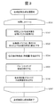
- FIG. 3 is a flowchart for explaining the composite image generation processing in the first embodiment.
- the composite image generation processing is executed by, for example, the image processing unit 216.
- the image processing unit 216 is realized by a program as described above, the operating subject is the CPU 211.
- the composite image generation process will be described with the image processing unit 216 as the operation subject, but it may be understood by replacing it with the CPU 211.
- Step 301 and Step 307 The image processing unit 216 repeatedly executes the processing from step 302 to step 306 for each image acquired by the imaging devices 2241 to 2441 at time t 1 to t n .
- the composite image generation processing for example, when the run until the end of surgery surgery start, surgery start time and t 1, the end of surgery time and tn.
- the imaging devices 2241 to 2441 capture, for example, 30 frames per second, the acquisition time interval of each image is 1/30 seconds.
- the composite image generation process may be executed in units of frames or in units of fields (one field image every 1/60 seconds).
- Step 302 The image processing unit 216 from the image memory (not shown), reads the image acquired by the imaging device 2241 to 2441 at time t k (e.g., three frames or more digital images). In this step, images of three frames or more captured at the same time are acquired.
- the image processing unit 216 calculates the positions of the imaging devices 2241 to 2441 attached to the respective distal end portions of the endoscope arms 22 to 24 in the body of the patient P (for example, in the abdominal cavity and the thoracic cavity). Specifically, the image processing unit 216 determines in advance, for example, information on rotation directions and angles (detected by a position detector) of the joint portions 221 to 223, 231 to 233, and 241 to 243 from a memory (not shown). Information on the lengths between the joints (movable elements) thus obtained and information on the length from a predetermined distal end of the endoscope arm to the nearest joint is obtained.
- the image processing unit 216 identifies each position by calculating the distance and rotation angle of each imaging device from a predetermined reference point (for example, the position of the joint unit 231 is used as a reference).
- the distance and the rotation angle from the reference point of each imaging device located at the distal end of the endoscope arm can be calculated by setting the point as a point and forming a spatial coordinate with this as the origin).
- the image processing unit 216 can also be referred to as a feature point (feature amount) for each image.
- the feature amount is a region around a feature point having a large change in shading that is converted into a feature vector by a pixel value or a differential value. ).
- the image processing unit 216 divides an image to be processed into block units (for example, blocks of 8 pixels ⁇ 8 pixels), and uses a Fourier transform, a discrete cosine transform, or the like to calculate a pixel value of each block. Convert to data in frequency domain. Thereby, the distribution of the frequency component in each block is acquired, and the feature point (feature amount) of each block can be extracted.
- an image in which the edge of each block is emphasized using an edge filter may be used as a feature point (feature amount).
- the image processing unit 216 performs pattern matching processing on each image.
- a pattern matching process (for example, calculating correlations for all pixels and blocks and setting a pixel or block having the highest correlation value as a pattern matching point) may be executed for all regions of each image. You may go in a limited way. In this case, speeding up and efficiency of processing can be achieved.
- When limiting the search range it is possible to determine a search range for blocks or pixels in which the feature amounts of the images match based on the information on the positions of the imaging devices 2241 to 2441 specified in step 303 ( For example, an area of 20% around each image is set as a search range).
- the image processing unit 216 executes pattern matching processing within the search range, and sets a matching position (a position with the highest correlation) in the search area of each image as a pattern matching point.
- Step 306 The image processing unit 216 connects the images at the position recognized as the pattern matching point in step 305 to generate a composite image.
- the pixel values of the images in the overlapping region may be slightly different (for example, there may be a difference in pixel values obtained by imaging even the same object because the imaging directions of the imaging devices are different).
- the images may be joined after removing the overlapping region from one of the images.
- a composite image can be generated by the method as described above, for example, a composite image may be generated using a method disclosed in Japanese Patent Laid-Open No. 10-178564.
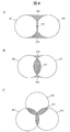
- FIG. 4 schematically shows the field of view of the imaging device, and is a diagram for explaining the reason for providing three or more endoscopes in the present embodiment.
- 4A and 4B show the field of view when two imaging devices are provided, and
- FIG. 4C shows the field of view when three imaging devices are provided.
- the field of view 401 and the field of view 402 of each imaging device should be as small as possible (in the case of FIG. 4A, the overlapping region 405 is small).
- the area of the overlapping region 405 can be reduced, but a blind spot 404 is generated between the visual field 401 and the visual field 402.
- FIG. 4B when the area of the blind spot 404 is reduced, the range that can be covered by the visual field 401 and the visual field 402 is reduced, and the area of the overlapping region 405 is increased.
- a sufficient field of view cannot be obtained for acquiring an image for observing the state of the operation in the patient's body (for example, in the abdominal cavity or the chest cavity) and the state around the organ to be operated.
- three or more imaging devices are provided and three fields of view are used to solve the conflicting problems as described above.
- the area of the overlapping region 405 is reduced, and the blind spot 404 formed by overlapping the two fields of view is eliminated.
- the entire field of view can be formed.
- three or more imaging devices 2241 to 2441 are used.
- the surgical system according to the second embodiment has the same configuration as the surgical system according to the first embodiment. However, in 2nd Embodiment, the structure of the endoscope apparatus 21 in the patient side cart 20 differs.
- a patient-side cart also referred to as a surgical robot
- an endoscope apparatus including an endoscope arm having a function of rotating at least a distal end portion of a cylindrical housing of an endoscope.
- a console device for operating a patient side cart.
- the optical axis of the imaging device forms a predetermined angle with the rotation axis of the distal end portion of the cylindrical housing, and the imaging device rotates the distal end portion of the cylindrical housing of the endoscope.
- a composite image is generated by connecting the acquired images and displayed on the display screen.
- a wide-angle visual field centering on the position of the endoscope can be provided to the surgeon. It is possible to perform an operation while visually confirming the state of the above (endoscopic operation can be realized while ensuring a wide field of view as in open surgery). Also in this case, for example, a foveal lens can be used as the lens of the imaging device.
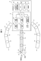
- FIG. 5 is a diagram illustrating a configuration example of the patient cart 20 according to the second embodiment.
- the difference from the first embodiment is that one endoscope arm 27 is attached, and the optical adapter 274 (including the imaging device 2741 and the illumination optical system 2742) at the distal end portion of the endoscope arm 27 is centered on the rotation axis. It is the point comprised so that rotation is possible.
- the distal end surface of the endoscope arm 27 is formed obliquely, and the optical axis of the imaging device 2741 forms a predetermined angle with the rotation axis.
- the angle formed by the optical axis of the imaging device 2741 and the rotation axis can be set to 1 ⁇ 2 of the angle of view (viewing angle) of the lens of the imaging device 2741, for example.
- the inclination angle of the distal end surface of the endoscope arm 27 can also be set to 1 ⁇ 2 of the angle of view of the lens of the imaging device 2741, for example.
- an image during surgery is captured by the imaging device 2741 while the optical adapter 274 at the distal end portion of the endoscope arm 27 is rotated around the rotation axis.
- Control of the rotation of the optical adapter 274 at the distal end portion of the endoscope arm 27 is performed by the endoscope arm drive control unit 214.
- the joint portion 273 is provided with a small (low-speed) actuator for rotating the tip portion different from the actuator for driving the joint, and a rotation drive mechanism (a rotation drive shaft connected to the tip portion and a rotation drive transmission shaft).
- the distal end portion of the endoscope arm 27 can be rotated by various kinds of gears (including, for example, a tip portion and a shaft of a small motor may be connected by a gear such as a bevel gear).
- gears including, for example, a tip portion and a shaft of a small motor may be connected by a gear such as a bevel gear.
- the rotational speed or the like of the distal end portion can be controlled by the endoscope arm drive control unit 214.
- the rotation of the distal end portion of the endoscope arm 27 can be detected by a position detector (for example, an encoder).
- a position detector provided at the joint closest to the tip portion can be used.
- the imaging control unit 215 stores an image captured while the imaging device 2741 rotates together with a time stamp in an image memory (not shown).
- the image processing unit 216 generates a composite image while matching the images acquired by the imaging control unit 215. The composite image generation process will be described later.
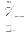
- the distal end portion of the endoscope arm 27 can be covered with a transparent sheath 61 having a rounded end portion, as shown in FIG. Thereby, it can prevent damaging the internal tissue of patient P during an operation.
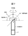
- FIG. 7 is a view for explaining a visual field secured when the distal end portion of the endoscope arm 27 is rotated.
- the viewing angle of the lens of the imaging device is, for example, 90 degrees.
- the angle between the optical axis of the lens and the rotation axis is set to 45 degrees, for example.
- the viewing angle ⁇ that can be secured by the rotation is 180 degrees, which is twice 90 degrees, and a wider field of view can be secured. become able to.
- the angle between the optical axis and the rotation axis is preferably 60 degrees (the inclination angle ⁇ of the tip surface is 30 degrees).
- the viewing angle ⁇ that can be secured by the rotation BR>] is 240 degrees, which is twice 120 degrees.
- the lens is arranged so that the optical axis of the lens having a viewing angle of 180 degrees forms 90 degrees with the rotation axis at the distal end portion of the endoscope arm 27, theoretically, the viewing angle ⁇ of 360 degrees is obtained. Can be secured.
- FIG. 8 is a flowchart for explaining the composite image generation processing in the second embodiment.
- the composite image generation processing is executed by, for example, the image processing unit 216.
- the image processing unit 216 is realized by a program as described above, the operating subject is the CPU 211.
- the composite image generation process will be described with the image processing unit 216 as the operation subject, but it may be understood by replacing it with the CPU 211.
- Step 801 and Step 806 The image processing unit 216 repeatedly executes the processing of Step 802 to Step 805 for each image acquired by the imaging device 2741 at time t 1 to t n .
- the composite image generation processing for example, when the run until the end of surgery surgery start, surgery start time and t 1, the end of surgery time and tn. For example, when the imaging device 2741 captures 30 frames per second, the acquisition time interval of each image is 1/30 second.
- the composite image generation process may be executed in units of frames or in units of fields (one field image every 1/60 seconds).
- Step 802 The image processing unit 216 is acquired from an image memory (not shown) by a composite image generated using images up to time t k (composite image generated in the previous process: previous composite image) and the imaging device 2741. Loaded images. In the case where the composite image at the initial stage of the process start not yet been generated (the case of t 1), the image at time t 1 and time t 2 in place of the composite image is read from the image memory.
- the image processing unit 216 extracts feature points (feature amounts) for the previous composite image and the image at time t k + 1 .
- the image processing unit 216 divides an image to be processed into block units (for example, blocks of 8 pixels ⁇ 8 pixels), and uses a Fourier transform, a discrete cosine transform, or the like to calculate a pixel value of each block. Convert to data in frequency domain. Thereby, the distribution of frequency components in each block is acquired, and the feature amount of each block can be extracted.
- an image in which the edge of each block is emphasized using an edge filter may be used as the feature amount.
- Step 804 The image processing unit 216 performs pattern matching processing on the previous composite image and the image at time t k + 1 .
- pattern matching can be executed in the same way as pattern matching in moving images.
- the image processing unit 216 can calculate, in advance, a search range (a distance that the image moves within one frame time (for example, 1/60 second) from the rotation speed (an image shift range)).
- the search range can be set with a margin that takes into account the range and error), and pattern matching is executed within the search area of each image (the position with the highest correlation). Let it be a point.
- Step 805 The image processing unit 216 generates a new composite image by connecting the previous composite image and the image at time t k + 1 at the position recognized as the pattern matching point in step 804. Note that when the rotation of the distal end portion of the endoscope arm 27 makes one round, a composite image at the viewing angle ⁇ is generated. The images acquired by the second and subsequent rotations are sequentially superimposed on appropriate positions (matched positions) of the already generated composite image.
- a composite image can be generated by the method as described above, for example, a composite image may be generated using a method disclosed in Japanese Patent Laid-Open No. 10-178564.
- ⁇ Low resolution mode and high resolution mode> an image acquired while rotating the distal end portion of the endoscope arm 27 is provided at a low resolution (low image quality: also referred to as the first resolution or the first image quality), and thus obtained by combining them.
- the resultant composite image is also displayed on the display screen of the display device 30 at a low resolution.
- the image acquired by stopping the rotation of the tip portion is displayed on the display screen of the display device 30 with high resolution (high image quality: also referred to as second resolution or second image quality (higher resolution than the first resolution)). Is done.
- the surgeon O operates the console device 10 to instruct to stop the rotation of the distal end portion when he / she wants to find a portion of interest in the composite image and to focus on the portion.
- the portion can be confirmed with a high-resolution image. Since the number of endoscopes to be inserted into the body of the patient P can be reduced as compared with the first embodiment, the endoscope apparatus and the surgery system according to the present embodiment can be made less invasive.
- a surgical system according to the third embodiment has the same configuration as the surgical system according to the first embodiment.
- the structure of the endoscope apparatus 21 in the patient side cart 20 differs.
- the endoscope device 21 is provided with only one endoscope arm 27 whose tip portion rotates.
- the third embodiment includes, for example, three or more endoscopes, and an endoscope including three or more endoscope arms having a function of rotating at least a distal end portion of a cylindrical housing of each endoscope.
- a surgical system including a patient side cart (also referred to as a surgical robot) including a mirror device and a console device for operating the patient side cart.
- the optical axis of each imaging device forms a predetermined angle with the rotation axis of the distal end portion of each cylindrical housing, and while rotating the distal end portion of the cylindrical housing of each endoscope
- a composite image is generated by connecting three or more images acquired by the imaging device and displayed on the display screen.
- an image with a wider field of view (eg, 360 degrees) can be provided to the surgeon. It is possible to perform an operation while visually confirming the state of the position in a wide range (an endoscopic operation can be realized while ensuring a wide field of view like an open abdominal operation). Also in this case, for example, a foveal lens can be used as the lens of the imaging device.
- an image with the rotation stopped is displayed on the display screen.
- an image acquired and displayed in a stopped state can have a higher image quality than an image acquired while rotating.
- the surgeon can visually confirm a desired portion in more detail.
- the surgeon may include information on the position of the target in the body from which the image is acquired in a state where the rotation is stopped. At this time, for example, an image acquired only by an imaging device capable of imaging the target position is displayed on the display screen.
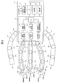
- FIG. 9 is a diagram illustrating a configuration example of the patient cart 20 according to the third embodiment.
- the difference from the first embodiment is that the tip portions of the three or more endoscope arms 27 to 29 rotate in the same manner as in the second embodiment.
- the difference from the second embodiment is that three or more endoscope arms 27 to 29 whose tip portions rotate are provided.
- each optical axis of the imaging devices 2741 to 2941 forms a predetermined angle with the rotation axis of each distal end portion.
- the angle formed by each optical axis of each of the imaging devices 2741 to 2941 and each rotation axis can be set to 1 ⁇ 2 of the angle of view (viewing angle) of each lens of the imaging devices 2741 to 2941, for example.
- the inclination angle of the distal end surfaces of the endoscope arms 27 to 29 can be set to, for example, (90—the viewing angle of the lens of the imaging device 2741 ⁇ 1 ⁇ 2) degrees.
- an image during surgery is captured by the imaging devices 2741 to 2941 while the optical adapters 274 to 294 at the distal end portions of the endoscope arms 27 to 29 are rotated about the rotation axis.
- the rotation control of the optical adapters 274 to 294 at the distal end portions of the endoscope arms 27 to 29 is performed by, for example, the endoscope arm drive control unit 214.
- each of the joint portions 273 to 293 is provided with a small (low-speed) motor for rotating the tip portion different from the motor for driving the joint, and a rotation drive mechanism (a rotation drive shaft coupled to the tip portion and
- the distal end portions of the endoscope arms 27 to 29 are rotated by various types of gears for rotational drive transmission (including, for example, a tip portion and a shaft of a small motor may be connected by a gear such as a bevel gear). it can.
- the rotational speed or the like of the distal end portion can be controlled by the endoscope arm drive control unit 214.
- the rotation of each distal end portion of the endoscope arms 27 to 29 can be detected by a position detector (for example, an encoder).
- each position detector provided at the joint closest to each tip portion can be used.
- the imaging control unit 215 stores an image captured while the imaging devices 2741 to 2941 rotate together with a time stamp in an image memory (not shown).
- the image processing unit 216 generates a composite image while matching the images acquired by the imaging control unit 215. The composite image generation process will be described later.
- the distal end portions of the endoscope arms 27 to 29 can be covered with, for example, a transparent sheath 61 having a rounded distal end portion, as in the second embodiment. It is. Thereby, it can prevent damaging the internal tissue of patient P during an operation.
- the composite image generation process in the third embodiment can be realized by combining the composite image generation process in the first embodiment (FIG. 3) and the composite image generation process in the second embodiment (FIG. 8). Is possible. For example, a composite image of images obtained by imaging while rotating each of the imaging devices 2741 to 2941 of the three or more endoscope arms 27 to 29 is generated according to the process of FIG. Thereby, three or more rotation composite images (also referred to as around view images) are generated. The three or more rotated synthesized images can be further synthesized according to the process of FIG. 3 to generate a final synthesized image.
- an image acquired while rotating the tip portions of the endoscope arms 27 to 29 has a low resolution (low image quality: also referred to as the first resolution or the first image quality). Therefore, a composite image of the rotation image of each tip portion and a final composite image obtained by further joining three or more composite images are also displayed on the display screen of the display device 30 at a low resolution.
- the image acquired by stopping the rotation of the tip portion has a high resolution (high image quality: also referred to as second resolution or second image quality (higher resolution than the first resolution)), as in the second embodiment. Is displayed on the display screen of the display device 30.
- the console device 10 when the operator O wants to find a portion of interest in the final composite image and to focus on it, for example, he / she operates the console device 10 to operate three or more endoscope arms. Instructing the rotation stop of at least one tip portion covering the priority observation portion among the tip portions 27 to 29 and confirming the portion with a high-resolution image by instructing the portion to be focused more closely Can do.
- a composite image representing the current state of the body (for example, intraperitoneal cavity or thoracic cavity) of the patient during surgery is displayed on the display screen of the display device 30.
- past images (regardless of whether or not they are composite images) may be displayed together (for example, on a multi-screen) on the display screen.
- a position where an image of the surgical site can be captured from the point in time when the distal end portions of the endoscope arms 22 to 24 (portion where the imaging device is attached) and the distal end portions of the endoscope arms 27 to 29 are inserted into the patient P
- the image group up to the time point of moving to is held in an image memory (not shown).
- an image around the insertion path of each endoscope arm and an image around the insertion path of the surgical instrument attached to each surgical arm are combined with the image during the current operation.
- the operator O can check whether the surgical instrument operated by the operator O is inserted while excessively compressing the internal organ of the patient P.
- all the tip portions of the three or more endoscope arms may not be configured to be rotatable (at least one of the endoscope arms 22 to 24).
- the distal end portion of the endoscope arm may be configured to be rotatable).
- the functions of the embodiments can also be realized by software program codes.
- a storage medium in which the program code is recorded is provided to the system or apparatus, and the computer (or CPU or MPU) of the system or apparatus reads the program code stored in the storage medium.
- the program code itself read from the storage medium realizes the functions of the above-described embodiment, and the program code itself and the storage medium storing it are included in this embodiment.
- a storage medium for supplying such program code for example, a flexible disk, CD-ROM, DVD-ROM, hard disk, optical disk, magneto-optical disk, CD-R, magnetic tape, nonvolatile memory card, ROM Etc. are used.
- an OS operating system
- the computer CPU or the like performs part or all of the actual processing based on the instruction of the program code.
- the program code of the software that realizes the functions of the embodiment is stored in a storage means such as a hard disk or memory of a system or apparatus or a storage medium such as a CD-RW or CD-R.
- the program code stored in the storage means or the storage medium may be read out and executed by the computer (or CPU or MPU) of the system or apparatus during storage.
Abstract
Description
第1の実施形態は、例えば、3以上の内視鏡アームを含む内視鏡装置を備える患者側カート(手術用ロボットとも言う)と、患者側カートを操作するためのコンソール装置と、を備える手術システムについて開示する。内視鏡装置では、例えば、3つ以上の内視鏡の各撮像デバイスが取得した各画像の特徴点を用いて記各画像を繋ぎ合わせて合成画像が生成され、当該合成画像が表示画面上に表示される。3つの視野の画像から合成画像を生成し、術者に提供するので、広範囲の画像を提供でき、術者が術中に様々な箇所を目視確認することが可能となる(開腹手術のような視野の広さを確保しながら内視鏡手術を実現することが可能)。また、例えば、3つ以上の内視鏡を適切な位置に配置することにより、体内(腹腔内や胸腔内)に内視鏡を挿入した際の内視鏡の進入経路の画像をリアルタイムに取得することも可能であり、この場合、内視鏡が体内の周辺臓器を圧迫しているか否かも確認することが可能となる。 (1) First Embodiment In the first embodiment, for example, a patient-side cart (also referred to as a surgical robot) including an endoscope apparatus including three or more endoscope arms and a patient-side cart are operated. And a console device. In the endoscope apparatus, for example, a composite image is generated by connecting the images using the feature points of the images acquired by the imaging devices of three or more endoscopes, and the composite image is displayed on the display screen. Is displayed. Since a composite image is generated from images of three fields of view and provided to the operator, a wide range of images can be provided, and the operator can visually confirm various locations during the operation (field of view such as laparotomy). Endoscopic surgery can be realized while ensuring a large area). In addition, for example, by placing three or more endoscopes at appropriate positions, an image of the entrance path of the endoscope when the endoscope is inserted into the body (in the abdominal cavity or thoracic cavity) is acquired in real time. In this case, it is also possible to confirm whether or not the endoscope presses the surrounding organs in the body.
図1は、実施形態による手術システム(手術用ロボットシステムとも呼ぶことができる)1の概略構成例を示す図である。 <Surgery system configuration>
FIG. 1 is a diagram illustrating a schematic configuration example of a surgical system (also referred to as a surgical robot system) 1 according to an embodiment.
図2は、第1の実施形態による患者側カート20の内部構成例を示す図である。患者側カート20は、ロボットアームを含むロボットカートであり、内視鏡及び内視鏡アームを制御する内視鏡装置21と、手術用アームを制御するその他の部分とに分けて説明することができる。内視鏡装置21を含む一方で手術用アームは含まないロボットカートをコンソール装置10で遠隔操作するシステムは内視鏡システムであり、ロボットカートが手術用アームも備え、コンソール装置10の操作により手術器具と内視鏡を操作することにより手術を行うシステムは手術システムである。 <Configuration of patient side cart>
FIG. 2 is a diagram illustrating an internal configuration example of the patient-
図3は、第1の実施形態における合成画像生成処理を説明するためのフローチャートである。当該合成画像生成処理は、例えば、画像処理部216によって実行されるが、上述のように画像処理部216をプログラムで実現した場合には動作主体はCPU211となる。以下では、画像処理部216を動作主体として合成画像生成処理について説明するが、CPU211と読み替えて理解しても良い。 <Composite image generation processing>
FIG. 3 is a flowchart for explaining the composite image generation processing in the first embodiment. The composite image generation processing is executed by, for example, the
画像処理部216は、時間t1~tnにおいて撮像デバイス2241乃至2441が取得した各画像に対してステップ302~ステップ306の処理を繰り返し実行する。当該合成画像生成処理は、例えば、手術開始から手術終了まで実行するとした場合、手術開始時間をt1とし、手術終了時間をtnとする。撮像デバイス2241乃至2441が例えば1秒間に30フレームを撮像する場合、各画像の取得時間間隔は1/30秒である。合成画像生成処理はフレーム単位で実行してもフィールド単位(1/60秒毎に1フィールド画像)で実行しても良い。 (I) Step 301 and Step 307
The
画像処理部216は、図示しない画像メモリから、時間tkにおいて撮像デバイス2241乃至2441によって取得された画像(例えば、3フレーム以上のデジタル画像)を読み込む。当該ステップでは、同一時間に撮像された3フレーム以上の画像が取得される。 (Ii) Step 302
The
画像処理部216は、内視鏡アーム22乃至24の各先端部分に取り付けられた撮像デバイス2241乃至2441の、患者Pの体内(例えば、腹腔内、胸腔内)における位置を算出する。具体的に、画像処理部216は、例えば、図示しないメモリから、複数の関節部221乃至223、231乃至233、241乃至243の回転方向及び角度の情報(位置検出器によって検知)と、予め決められた各関節部間(可動要素)の長さの情報と、予め決められた内視鏡アーム先端からそれに一番近い関節部までの長さの情報と、を取得する。画像処理部216は、これらの情報に基づいて、予め決められた基準点からの各撮像デバイスの距離及び回転角度を算出することによりそれぞれの位置を特定する(例えば、関節部231の位置を基準点として設定し、これを原点として空間座標を形成することにより内視鏡アーム先端に位置する各撮像デバイスの基準点からの距離及び回転角度を算出することができる)。 (Iii) Step 303
The
画像処理部216は、各画像について特徴点(特徴量と言うことも可能である。特徴量は、濃淡の変化が大きい特徴点周りの領域を画素値や微分値により特徴ベクトルにしたものである)を抽出する。具体的に、画像処理部216は、例えば、処理対象の画像をブロック単位(例えば、8ピクセル×8ピクセルのブロック)に分割し、フーリエ変換や離散コサイン変換などを用いて各ブロックの画素値を周波数領域におけるデータに変換する。これにより、各ブロックにおける周波数成分の分布が取得され、各ブロックの特徴点(特徴量)を抽出することができる。フーリエ変換や離散コサイン変換の他に、エッジフィルタを用いて各ブロックのエッジを強調した画像を特徴点(特徴量)としても良い。 (Iv) Step 304
The
画像処理部216は、各画像についてパターンマッチング処理を実行する。各画像の全ての領域についてパターンマッチング処理(例えば、全ての画素やブロックについて相関を計算し、最も相関値が高い画素或いはブロックをパターン一致点とする)を実行しても良いが、探索範囲を限定して行っても良い。この場合、処理の迅速化及び効率化を図ることができる。探索範囲を限定する場合、ステップ303で特定された撮像デバイス2241乃至2441のそれぞれの位置の情報に基づいて、各画像の特徴量が一致するブロック或いは画素を探索する範囲を決定することができる(例えば、各画像の周辺20%の領域を探索範囲とするなど)。画像処理部216は、その探索範囲内でパターンマッチング処理を実行し、各画像の探索領域においてマッチングする位置(相関が最も高い位置)をパターン一致点とする。 (V) Step 305
The
画像処理部216は、ステップ305でパターン一致点と認識された位置において、各画像を繋ぎ合わせて合成画像を生成する。なお、パターンマッチング処理を実行すると、各画像において互いに重なり合う領域が検出される。当該重なり合う領域における各画像の画素値は多少異なる場合がある(例えば、各撮像デバイスの撮像方向が異なるため同じ対象物でも撮像して得られる画素値に差が生じる場合がある)ため、重ね合わせる画像の一方から重なり合う領域を取り除いてから各画像を繋ぎ合わせても良い。
以上のような方法で合成画像を生成することができるが、例えば特開平10-178564号公報で開示された方法を用いて合成画像を生成しても良い。 (Vi) Step 306
The
Although a composite image can be generated by the method as described above, for example, a composite image may be generated using a method disclosed in Japanese Patent Laid-Open No. 10-178564.
図4は、撮像デバイスの視野を模式的に示し、本実施形態において3つ以上の内視鏡を設けた理由を説明するための図である。図4A及び図4Bは撮像デバイスを2つ設けた場合の視野を示し、図4Cは撮像デバイスを3つ設けた場合の視野を示している。 <Reason for using three or more endoscopes>
FIG. 4 schematically shows the field of view of the imaging device, and is a diagram for explaining the reason for providing three or more endoscopes in the present embodiment. 4A and 4B show the field of view when two imaging devices are provided, and FIG. 4C shows the field of view when three imaging devices are provided.
以上の理由により、本開示の第1の実施形態では、3つ以上の撮像デバイス2241乃至2441を用いることとしている。 Therefore, in the present disclosure, three or more imaging devices are provided and three fields of view are used to solve the conflicting problems as described above. For example, as shown in FIG. 4C, the area of the
For the above reason, in the first embodiment of the present disclosure, three or more imaging devices 2241 to 2441 are used.
第2の実施形態による手術システムは、第1の実施形態による手術システムと同様の構成を備えている。ただし、第2の実施形態では、患者側カート20における内視鏡装置21の構成が異なっている。 (2) Second Embodiment The surgical system according to the second embodiment has the same configuration as the surgical system according to the first embodiment. However, in 2nd Embodiment, the structure of the
図5は、第2の実施形態による患者側カート20の構成例を示す図である。第1の実施形態と異なる点は、内視鏡アーム27が1つ取り付けられ、内視鏡アーム27の先端部分の光学アダプタ274(撮像デバイス2741及び照明光学系2742を含む)を回転軸中心に回転可能に構成されている点である。また、内視鏡アーム27の先端面が斜めに形成され、撮像デバイス2741の光軸が回転軸と所定の角度をなしている。撮像デバイス2741の光軸と回転軸とのなす角度は、例えば、撮像デバイス2741のレンズの画角(視野角)の1/2に設定することができる。この場合、内視鏡アーム27の先端面の傾斜角も例えば、撮像デバイス2741のレンズの画角の1/2とすることができる。 <Configuration of
FIG. 5 is a diagram illustrating a configuration example of the
撮像制御部215は、撮像デバイス2741が回転しながら撮像した画像をタイムスタンプと共に、図示しない画像メモリに格納する。
画像処理部216は、撮像制御部215が取得した画像間のマッチングを取りながら合成画像を生成する。合成画像生成処理については後述する。 In the second embodiment, an image during surgery is captured by the
The
The
図7は、内視鏡アーム27の先端部分を回転させたときに確保される視野について説明するための図である。 <Field of view secured when the tip is rotated>
FIG. 7 is a view for explaining a visual field secured when the distal end portion of the
図8は、第2の実施形態における合成画像生成処理を説明するためのフローチャートである。当該合成画像生成処理は、例えば、画像処理部216によって実行されるが、上述のように画像処理部216をプログラムで実現した場合には動作主体はCPU211となる。以下では、画像処理部216を動作主体として合成画像生成処理について説明するが、CPU211と読み替えて理解しても良い。 <Composite image generation processing>
FIG. 8 is a flowchart for explaining the composite image generation processing in the second embodiment. The composite image generation processing is executed by, for example, the
画像処理部216は、時間t1~tnにおいて撮像デバイス2741が取得した各画像に対してステップ802~ステップ805の処理を繰り返し実行する。当該合成画像生成処理は、例えば、手術開始から手術終了まで実行するとした場合、手術開始時間をt1とし、手術終了時間をtnとする。撮像デバイス2741が例えば1秒間に30フレームを撮像する場合、各画像の取得時間間隔は1/30秒である。合成画像生成処理はフレーム単位で実行してもフィールド単位(1/60秒毎に1フィールド画像)で実行しても良い。 (I) Step 801 and Step 806
The
画像処理部216は、図示しない画像メモリから、時間tkまでの画像を用いて生成された合成画像(前回の処理で生成された合成画像:前回の合成画像)と、撮像デバイス2741によって取得された画像を読み込む。処理開始の初期段階で合成画像がまだ生成されていない場合(t1の場合)には、合成画像の代わりに時間t1と時間t2における画像が画像メモリから読み込まれる。 (Ii) Step 802
The
画像処理部216は、前回の合成画像と時間tk+1おける画像について特徴点(特徴量)を抽出する。具体的に、画像処理部216は、例えば、処理対象の画像をブロック単位(例えば、8ピクセル×8ピクセルのブロック)に分割し、フーリエ変換や離散コサイン変換などを用いて各ブロックの画素値を周波数領域におけるデータに変換する。これにより、各ブロックにおける周波数成分の分布が取得され、各ブロックの特徴量を抽出することができる。フーリエ変換や離散コサイン変換の他に、エッジフィルタを用いて各ブロックのエッジを強調した画像を特徴量としても良い。前回の合成画像について既に特徴量を抽出している場合には、例えば、図示しない画像メモリから読み込むだけで良い。 (Iii) Step 803
The
画像処理部216は、前回の合成画像と時間tk+1おける画像と対してパターンマッチング処理を実行する。第2の実施形態では、撮像デバイス2741は回転しているので、パターンマッチングは動画におけるパターンマッチングと同等に実行することができる。具体的には、画像処理部216は、例えば、予め探索範囲(回転速度から画像が1フレーム時間(例えば、1/60秒間)に移動する距離(画像がずれる範囲)を算出することが可能であり、その範囲と誤差を考慮したマージンによって探索範囲を設定することが可能である)内でパターンマッチング処理を実行し、各画像の探索領域においてマッチングする位置(相関が最も高い位置)をパターン一致点とする。 (Iv) Step 804
The
画像処理部216は、ステップ804でパターン一致点と認識された位置において、前回の合成画像と時間tk+1おける画像とを繋ぎ合わせて新たな合成画像を生成する。なお、内視鏡アーム27の先端部分の回転が一周すると、視野角θにおける合成画像が生成されることなる。2周目以降の回転によって取得された画像は、既に生成された合成画像の適切な位置(マッチングが取れた位置)に逐次重畳されることになる。
以上のような方法で合成画像を生成することができるが、例えば特開平10-178564号公報で開示された方法を用いて合成画像を生成しても良い。 (V) Step 805
The
Although a composite image can be generated by the method as described above, for example, a composite image may be generated using a method disclosed in Japanese Patent Laid-Open No. 10-178564.
本実施形態では、例えば、内視鏡アーム27の先端部分を回転させながら取得した画像は低解像度(低画質:第1解像度或いは第1画質ともいう)で提供され、よってそれらを合成して得られる合成画像も低解像度で表示装置30の表示画面上に表示される。一方、当該先端部分の回転を停止させて取得した画像は高解像度(高画質:第2解像度或いは第2画質ともいう(第1解像度よりも高解像度))で表示装置30の表示画面上に表示される。 <Low resolution mode and high resolution mode>
In the present embodiment, for example, an image acquired while rotating the distal end portion of the
本実施形態に係る内視鏡装置及び手術システムは、第1の実施形態と比べて、患者Pの体内に挿入する内視鏡の数を少なくできるため、より低侵襲とすることができる。 For example, the surgeon O operates the
Since the number of endoscopes to be inserted into the body of the patient P can be reduced as compared with the first embodiment, the endoscope apparatus and the surgery system according to the present embodiment can be made less invasive.
第3の実施形態による手術システムは、第1の実施形態による手術システムと同様の構成を備えている。ただし、第3の実施形態では、患者側カート20における内視鏡装置21の構成が異なっている。第2の実施形態では、内視鏡装置21において、先端部分が回転する内視鏡アーム27が1つだけで設けられているが、第3の実施形態では、先端部分が回転する内視鏡アームが3つ以上設けられている点で異なる。 (3) Third Embodiment A surgical system according to the third embodiment has the same configuration as the surgical system according to the first embodiment. However, in 3rd Embodiment, the structure of the
図9は、第3の実施形態による患者側カート20の構成例を示す図である。第1の実施形態と異なる点は、3つ以上の内視鏡アーム27乃至29の先端部分が第2の実施形態と同様に回転することである。第2の実施形態と異なる点は、先端部分が回転する内視鏡アーム27乃至29が3つ以上設けられていることである。 <Configuration of patient side cart>
FIG. 9 is a diagram illustrating a configuration example of the
撮像制御部215は、撮像デバイス2741乃至2941が回転しながら撮像した画像をタイムスタンプと共に、図示しない画像メモリに格納する。
画像処理部216は、撮像制御部215が取得した画像間のマッチングを取りながら合成画像を生成する。合成画像生成処理については後述する。 In the third embodiment, for example, an image during surgery is captured by the
The
The
第3の実施形態における合成画像生成処理は、第1の実施形態における合成画像生成処理(図3)と第2の実施形態における合成画像生成処理(図8)とを組み合わせることによって実現することが可能である。例えば、3つ以上の内視鏡アーム27乃至29の撮像デバイス2741乃至2941のそれぞれを回転させながら撮像して得られた画像の合成画像を図8の処理に従って生成する。これにより、3つ以上の回転合成画像(アラウンドビュー画像とも呼ぶ)が生成される。この3つ以上の回転合成画像をさらに図3の処理に従って合成し、最終的な合成画像を生成することができる。 <Composite image generation processing>
The composite image generation process in the third embodiment can be realized by combining the composite image generation process in the first embodiment (FIG. 3) and the composite image generation process in the second embodiment (FIG. 8). Is possible. For example, a composite image of images obtained by imaging while rotating each of the
本実施形態では、第2の実施形態と同様に、例えば、内視鏡アーム27乃至29の先端部分を回転させながら取得した画像は低解像度(低画質:第1解像度或いは第1画質ともいう)で提供され、よって各先端部分の回転画像の合成画像、及び3つ以上の合成画像をさらに繋ぎ合わせて得られる最終的な合成画像も低解像度で表示装置30の表示画面上に表示される。一方、当該先端部分の回転を停止させて取得した画像は、第2の実施形態と同様に、高解像度(高画質:第2解像度或いは第2画質ともいう(第1解像度よりも高解像度))で表示装置30の表示画面上に表示される。 <Low resolution mode and high resolution mode>
In the present embodiment, as in the second embodiment, for example, an image acquired while rotating the tip portions of the
(i)第1乃至第3の実施形態では、手術中の患者の体内(例えば、腹腔内或いは胸腔内)の現在の様子を表す合成画像が表示装置30の表示画面上に表示されるが、過去の画像(合成画像か否かに関係なく)を合わせて(例えば、マルチ画面で)表示画面上に表示しても良い。例えば、内視鏡アーム22乃至24の先端部分(撮像デバイスが取り付けられた部分)及び内視鏡アーム27乃至29の先端部分を患者Pの体内に挿入した時点から手術部位の画像を撮像できる位置に移動する時点までの間の画像群は図示しない画像メモリに保持されている。このため、各内視鏡アームの挿入経路付近の画像、及び各手術用アームに取り付けられた手術器具の挿入経路周辺の画像(共に過去に撮像した画像)を現在の手術中の画像と併せて表示画面上に表示することにより、例えば、術者Oは、自身が操作する手術器具が患者Pの体内の臓器を過度に圧迫しながら挿入されていないかを確認することができるようになる。 (4) Modification (i) In the first to third embodiments, a composite image representing the current state of the body (for example, intraperitoneal cavity or thoracic cavity) of the patient during surgery is displayed on the display screen of the
10 コンソール装置
20 患者側カート
21 内視鏡装置
22、23、24、27、28、29 内視鏡アーム
25、26 手術用アーム
30 表示装置 DESCRIPTION OF SYMBOLS 1
Claims (20)
- それぞれが筒状筐体の先端部分に撮像デバイスを備え、被検体の体内の画像を取得する、3つ以上の内視鏡と、
前記3つ以上の内視鏡に電気的に接続し、前記3つ以上の内視鏡のそれぞれが取得した画像を処理する制御装置と、を備え、
前記制御装置は、前記各撮像デバイスが取得した各画像の特徴点を用いて前記各画像を繋ぎ合わせて合成画像を生成する、内視鏡装置。 Three or more endoscopes each having an imaging device at the distal end portion of the cylindrical housing and acquiring an image in the body of the subject; and
A controller that electrically connects to the three or more endoscopes and processes images acquired by each of the three or more endoscopes;
The said control apparatus is an endoscope apparatus which produces | generates a synthesized image by connecting each said image using the feature point of each image which each said imaging device acquired. - 請求項1において、
前記3つ以上の内視鏡が取得する少なくとも3つの画像には、互いに重なり合う領域が存在し、
前記制御装置は、前記各画像の特徴点を用いて前記互いに重なり合う領域を特定し、前記合成画像を生成する、内視鏡装置。 In claim 1,
The at least three images acquired by the three or more endoscopes have areas that overlap each other,
The endoscope apparatus is an endoscope apparatus that identifies the overlapping area using the feature points of the images and generates the composite image. - 請求項1又は2において、
前記制御装置は、さらに、前記3つ以上の内視鏡の各撮像デバイスの位置情報を用いて前記各画像を繋ぎ合わせる、内視鏡装置。 In claim 1 or 2,
The said control apparatus is an endoscope apparatus which joins each said image further using the positional information on each imaging device of the said three or more endoscopes. - 請求項1乃至3の何れか1項において、
前記3つ以上の内視鏡が備える各撮像デバイスは、視野角が90度以上のレンズを含む、内視鏡装置。 In any one of Claims 1 thru | or 3,
Each of the imaging devices included in the three or more endoscopes is an endoscope apparatus including a lens having a viewing angle of 90 degrees or more. - 請求項1乃至4の何れか1項において、
さらに、画像を格納するためのメモリを備え、
前記制御装置は、前記3つ以上の内視鏡が前記被検体の体内に挿入されたときから前記各撮像デバイスによって取得された合成前の画像と、前記3つ以上の内視鏡が前記被検体の体内に挿入されたときからの前記合成画像と、を前記メモリに格納し、入力された指示に応答して前記メモリから所定時点における前記合成画像を読み出す、内視鏡装置。 In any one of Claims 1 thru | or 4,
Furthermore, a memory for storing images is provided,
The control device includes a pre-combine image acquired by each imaging device from when the three or more endoscopes are inserted into the body of the subject, and the three or more endoscopes are the subject. An endoscope apparatus that stores in the memory the composite image that has been inserted into the body of a specimen, and reads out the composite image at a predetermined time from the memory in response to an input instruction. - 筒状筐体の先端部分に撮像デバイスを備え、被検体の体内の画像を取得する内視鏡と、
前記内視鏡の筒状筐体の少なくとも先端部分を回転させる回転駆動制御部と、
前記内視鏡に電気的に接続し、前記内視鏡が取得した画像を処理する制御装置と、を備え、
前記撮像デバイスの光軸は、前記筒状筐体の先端部分の回転軸と所定の角度をなし、
前記制御装置は、前記内視鏡の前記筒状筐体の先端部分を回転させながら前記撮像デバイスで取得した画像を繋ぎ合わせて合成画像を生成する、内視鏡装置。 An endoscope that includes an imaging device at the tip of the cylindrical housing and acquires an image of the inside of the subject;
A rotation drive control unit that rotates at least a distal end portion of the cylindrical casing of the endoscope;
A controller that electrically connects to the endoscope and processes an image acquired by the endoscope;
The optical axis of the imaging device forms a predetermined angle with the rotation axis of the tip portion of the cylindrical housing,
The said control apparatus is an endoscope apparatus which joins the image acquired with the said imaging device and produces | generates a synthesized image, rotating the front-end | tip part of the said cylindrical housing | casing of the said endoscope. - 請求項6において、
前記制御装置は、前記画像の特徴点を用いて前記画像を繋ぎ合わせる、内視鏡装置。 In claim 6,
The said control apparatus is an endoscope apparatus which connects the said image using the feature point of the said image. - 請求項6又は7において、
前記回転軸は、前記筒状筐体の長手方向と同一であり、
前記撮像デバイスは、前記回転軸に対して傾斜して前記筒状筐体の先端部分に配置され、前記撮像デバイスの光軸と前記回転軸とが前記所定の角度をなす、内視鏡装置。 In claim 6 or 7,
The rotation axis is the same as the longitudinal direction of the cylindrical housing,
The endoscope apparatus, wherein the imaging device is disposed at a distal end portion of the cylindrical housing so as to be inclined with respect to the rotation axis, and an optical axis of the imaging device and the rotation axis make the predetermined angle. - 請求項6乃至8の何れか1項において、
前記撮像デバイスの光軸と前記回転軸とがなす前記所定の角度は、前記撮像デバイスのレンズの視野角の1/2である、内視鏡装置。 In any one of Claims 6 thru | or 8,
The endoscope apparatus, wherein the predetermined angle formed by the optical axis of the imaging device and the rotation axis is ½ of a viewing angle of a lens of the imaging device. - 請求項6乃至9の何れか1項において、
前記撮像デバイスのレンズは、中心窩レンズである、内視鏡装置。 In any one of Claims 6 thru | or 9,
An endoscope apparatus in which a lens of the imaging device is a foveal lens. - 請求項6乃至10の何れか1項において、
前記筒状筐体の先端部分には、シースが取り付けられている、内視鏡装置。 In any one of Claims 6 thru | or 10,
An endoscope apparatus in which a sheath is attached to a distal end portion of the cylindrical casing. - 請求項6乃至11の何れか1項において、
前記内視鏡を3つ以上備え、
前記回転駆動部は、前記3つ以上の内視鏡の筒状筐体の少なくとも先端部分をそれぞれ回転させ、
前記3つ以上の内視鏡の各撮像デバイスの光軸は、対応する前記筒状筐体の先端部分の回転角と所定の角度をなし、
前記制御装置は、前記3つ以上の内視鏡の各筒状筐体の先端部分を回転させながら前記各撮像デバイスで取得した各画像を、前記先端部分を回転させながら取得した前記各画像の特徴点と用いて繋ぎ合わせて合成画像を生成する、内視鏡装置。 In any one of Claims 6 thru | or 11,
Including three or more endoscopes;
The rotation driving unit rotates at least the tip portions of the cylindrical casings of the three or more endoscopes,
The optical axis of each imaging device of the three or more endoscopes forms a predetermined angle with the rotation angle of the corresponding tip portion of the cylindrical housing,
The control device is configured to obtain images acquired by the imaging devices while rotating the tip portions of the cylindrical housings of the three or more endoscopes. An endoscope apparatus that generates a composite image by connecting with feature points. - 請求項12において、
さらに、前記3つ以上の内視鏡の筒状筐体の少なくとも先端部分の回転を検知する位置検出器を備える、内視鏡装置。 In claim 12,
An endoscope apparatus further comprising a position detector that detects rotation of at least a tip portion of the cylindrical housing of the three or more endoscopes. - 請求項12又は13において、
前記制御装置は、入力された指示に応答して、前記各筒状筐体の先端部分の回転を停止し、当該回転を停止した状態で撮像デバイスの少なくとも1つによって取得された画像を取得する、内視鏡装置。 In claim 12 or 13,
In response to the input instruction, the control device stops the rotation of the distal end portion of each cylindrical housing, and acquires an image acquired by at least one of the imaging devices in a state where the rotation is stopped. Endoscope device. - 請求項14において、
前記回転を停止した状態で取得され表示される画像は、前記各筒状筐体の先端部分を回転させながら取得した画像よりも高画質である、内視鏡装置。 In claim 14,
An endoscope apparatus in which an image acquired and displayed in a state where the rotation is stopped is higher in image quality than an image acquired while rotating a tip portion of each cylindrical casing. - 請求項14又は15において、
前記入力された指示は、前記回転を停止した状態で画像を取得する前記体内の対象の位置の情報を含み、
前記制御装置は、前記対象の位置を撮像可能な撮像デバイスによってのみ取得された画像を取得する、内視鏡装置。 In claim 14 or 15,
The input instruction includes information on the position of the target in the body that acquires an image in a state where the rotation is stopped,
The endoscope apparatus is an endoscope apparatus that acquires an image acquired only by an imaging device capable of imaging the position of the target. - 内視鏡システムであって、
内視鏡と、内視鏡を保持する内視鏡アームを含む内視鏡装置を備えるロボットカートと、
前記ロボットカートの前記内視鏡アームを操作するための指示を送信するコンソール装置と、
前記内視鏡装置によって撮像された画像を表示画面上に表示する表示装置と、を備え、
前記内視鏡装置は、
それぞれが筒状筐体の先端部分に撮像デバイスを備え、被検体の体内の画像を取得する、3つ以上の内視鏡と、
前記3つ以上の内視鏡に電気的に接続し、前記3つ以上の内視鏡のそれぞれが取得した画像を処理する制御装置と、を備え、
前記制御装置は、前記各撮像デバイスが取得した各画像の特徴点を用いて前記各画像を繋ぎ合わせて合成画像を生成する、内視鏡システム。 An endoscope system,
An endoscope, and a robot cart including an endoscope apparatus including an endoscope arm that holds the endoscope;
A console device for transmitting instructions for operating the endoscope arm of the robot cart;
A display device that displays an image captured by the endoscope device on a display screen,
The endoscope apparatus is
Three or more endoscopes each having an imaging device at the distal end portion of the cylindrical housing and acquiring an image in the body of the subject; and
A controller that electrically connects to the three or more endoscopes and processes images acquired by each of the three or more endoscopes;
The said control apparatus is an endoscope system which connects each said image using the feature point of each image which each said imaging device acquired, and produces | generates a synthesized image. - 内視鏡システムであって、
内視鏡と、内視鏡を保持する内視鏡アームを含む内視鏡装置を備えるロボットカートと、
前記ロボットカートの前記内視鏡アームを操作するための指示を送信するコンソール装置と、
前記内視鏡装置によって撮像された画像を表示画面上に表示する表示装置と、を備え、
前記内視鏡装置は、
筒状筐体の先端部分に撮像デバイスを備え、被検体の体内の画像を取得する内視鏡と、
前記内視鏡の筒状筐体の少なくとも先端部分を回転させる回転駆動部と、
前記内視鏡に電気的に接続し、前記内視鏡が取得した画像を処理する制御装置と、を備え、
前記撮像デバイスの光軸は、前記筒状筐体の先端部分の回転軸と所定の角度をなし、
前記制御装置は、前記内視鏡の前記筒状筐体の先端部分を回転させながら前記撮像デバイスで取得した画像を繋ぎ合わせて合成画像を生成する、内視鏡システム。 An endoscope system,
An endoscope, and a robot cart including an endoscope apparatus including an endoscope arm that holds the endoscope;
A console device for transmitting instructions for operating the endoscope arm of the robot cart;
A display device that displays an image captured by the endoscope device on a display screen,
The endoscope apparatus is
An endoscope that includes an imaging device at the tip of the cylindrical housing and acquires an image of the inside of the subject;
A rotation drive unit that rotates at least a tip portion of the cylindrical casing of the endoscope;
A controller that electrically connects to the endoscope and processes an image acquired by the endoscope;
The optical axis of the imaging device forms a predetermined angle with the rotation axis of the tip portion of the cylindrical housing,
The said control apparatus is an endoscope system which joins the image acquired with the said imaging device and produces | generates a synthesized image, rotating the front-end | tip part of the said cylindrical housing | casing of the said endoscope. - 請求項18において、
前記内視鏡装置は、前記内視鏡を3つ以上備え、
前記回転駆動部は、前記3つ以上の内視鏡の筒状筐体の少なくとも先端部分をそれぞれ回転させ、
前記3つ以上の内視鏡の各撮像デバイスの光軸は、対応する前記筒状筐体の先端部分の回転角と所定の角度をなし、
前記制御装置は、前記3つ以上の内視鏡の各筒状筐体の先端部分を回転させながら前記各撮像デバイスで取得した各画像を、前記先端部分を回転させながら取得した前記各画像の特徴点を用いて、繋ぎ合わせて合成画像を生成する、内視鏡システム。 In claim 18,
The endoscope apparatus includes three or more endoscopes,
The rotation driving unit rotates at least the tip portions of the cylindrical casings of the three or more endoscopes,
The optical axis of each imaging device of the three or more endoscopes forms a predetermined angle with the rotation angle of the corresponding tip portion of the cylindrical housing,
The control device is configured to obtain images acquired by the imaging devices while rotating the tip portions of the cylindrical housings of the three or more endoscopes. An endoscope system that uses a feature point to create a composite image by stitching together. - 請求項17乃至19の何れか1項に記載の内視鏡システムを備え、
前記ロボットカートは、手術器具が取り付けられる手術用アームをさらに備え、
前記コンソール装置は、前記手術用アームを操作するための指示を送信する、手術システム。 An endoscope system according to any one of claims 17 to 19, comprising:
The robot cart further includes a surgical arm to which a surgical instrument is attached,
The console device transmits an instruction for operating the surgical arm.
Priority Applications (4)
| Application Number | Priority Date | Filing Date | Title |
|---|---|---|---|
| PCT/JP2016/059672 WO2017163407A1 (en) | 2016-03-25 | 2016-03-25 | Endoscope device, endoscope system, and surgery system provided with same |
| EP16895438.6A EP3434170B1 (en) | 2016-03-25 | 2016-03-25 | Endoscope apparatus and endoscope system including the same |
| JP2018506729A JP6598982B2 (en) | 2016-03-25 | 2016-03-25 | Endoscope apparatus, endoscope system, and surgical system including the same |
| US16/129,326 US20190008367A1 (en) | 2016-03-25 | 2018-09-12 | Endoscope apparatus, endoscope system and surgical system including the same |
Applications Claiming Priority (1)
| Application Number | Priority Date | Filing Date | Title |
|---|---|---|---|
| PCT/JP2016/059672 WO2017163407A1 (en) | 2016-03-25 | 2016-03-25 | Endoscope device, endoscope system, and surgery system provided with same |
Related Child Applications (1)
| Application Number | Title | Priority Date | Filing Date |
|---|---|---|---|
| US16/129,326 Continuation US20190008367A1 (en) | 2016-03-25 | 2018-09-12 | Endoscope apparatus, endoscope system and surgical system including the same |
Publications (1)
| Publication Number | Publication Date |
|---|---|
| WO2017163407A1 true WO2017163407A1 (en) | 2017-09-28 |
Family
ID=59900080
Family Applications (1)
| Application Number | Title | Priority Date | Filing Date |
|---|---|---|---|
| PCT/JP2016/059672 WO2017163407A1 (en) | 2016-03-25 | 2016-03-25 | Endoscope device, endoscope system, and surgery system provided with same |
Country Status (4)
| Country | Link |
|---|---|
| US (1) | US20190008367A1 (en) |
| EP (1) | EP3434170B1 (en) |
| JP (1) | JP6598982B2 (en) |
| WO (1) | WO2017163407A1 (en) |
Cited By (4)
| Publication number | Priority date | Publication date | Assignee | Title |
|---|---|---|---|---|
| CN109330692A (en) * | 2018-07-31 | 2019-02-15 | 深圳市精锋医疗科技有限公司 | The visual field is preferably from operation apparatus assembly and operating robot |
| CN111278344A (en) * | 2017-11-01 | 2020-06-12 | 索尼公司 | Surgical arm system and surgical arm control system |
| WO2021152754A1 (en) * | 2020-01-29 | 2021-08-05 | オリンパス株式会社 | Image processing device, observation system, and observation method |
| WO2022092026A1 (en) * | 2020-10-29 | 2022-05-05 | 国立大学法人東海国立大学機構 | Surgery assistance tool and surgery assistance system |
Families Citing this family (5)
| Publication number | Priority date | Publication date | Assignee | Title |
|---|---|---|---|---|
| JP7247702B2 (en) * | 2019-03-27 | 2023-03-29 | ソニーグループ株式会社 | Endoscope system, endoscope control method, and imaging control device |
| US11278361B2 (en) | 2019-05-21 | 2022-03-22 | Verb Surgical Inc. | Sensors for touch-free control of surgical robotic systems |
| US11504193B2 (en) * | 2019-05-21 | 2022-11-22 | Verb Surgical Inc. | Proximity sensors for surgical robotic arm manipulation |
| US20230017411A1 (en) * | 2021-07-14 | 2023-01-19 | Cilag Gmbh International | Endoscope with source and pixel level image modulation for multispectral imaging |
| US20230100698A1 (en) * | 2021-09-29 | 2023-03-30 | Cilag Gmbh International | Methods for Controlling Cooperative Surgical Instruments |
Citations (8)
| Publication number | Priority date | Publication date | Assignee | Title |
|---|---|---|---|---|
| JPH07327921A (en) * | 1994-06-14 | 1995-12-19 | Olympus Optical Co Ltd | Medical image pickup system |
| JPH08332169A (en) * | 1995-06-08 | 1996-12-17 | Olympus Optical Co Ltd | Intracoelomscope |
| JPH1043127A (en) * | 1996-08-02 | 1998-02-17 | Tsunehisa Shimoda | Medical endoscope |
| JPH11113836A (en) * | 1997-10-20 | 1999-04-27 | Olympus Optical Co Ltd | Endoscope device |
| JP2004289225A (en) * | 2003-03-19 | 2004-10-14 | Minolta Co Ltd | Imaging apparatus |
| JP2006288869A (en) * | 2005-04-13 | 2006-10-26 | Hitachi Medical Corp | Display device of endoscopic image |
| JP2008528130A (en) * | 2005-01-24 | 2008-07-31 | インテュイティブ サージカル, インコーポレイテッド | Modular manipulator support for robotic surgery |
| WO2010050243A1 (en) * | 2008-10-31 | 2010-05-06 | 合同会社ジャパン・メディカル・クリエーティブ | Surgery device |
Family Cites Families (3)
| Publication number | Priority date | Publication date | Assignee | Title |
|---|---|---|---|---|
| DE102012025100A1 (en) * | 2012-12-20 | 2014-06-26 | avateramedical GmBH | Decoupled multi-camera system for minimally invasive surgery |
| US20150045619A1 (en) * | 2013-08-09 | 2015-02-12 | Chang Bing Show Chwan Memorial Hospital | System and method for mosaicing endoscope images using wide angle view endoscope |
| WO2015191784A1 (en) * | 2014-06-10 | 2015-12-17 | Nitesh Ratnakar | Endoscope with multiple views and novel configurations adapted thereto |
-
2016
- 2016-03-25 WO PCT/JP2016/059672 patent/WO2017163407A1/en active Application Filing
- 2016-03-25 EP EP16895438.6A patent/EP3434170B1/en active Active
- 2016-03-25 JP JP2018506729A patent/JP6598982B2/en active Active
-
2018
- 2018-09-12 US US16/129,326 patent/US20190008367A1/en not_active Abandoned
Patent Citations (8)
| Publication number | Priority date | Publication date | Assignee | Title |
|---|---|---|---|---|
| JPH07327921A (en) * | 1994-06-14 | 1995-12-19 | Olympus Optical Co Ltd | Medical image pickup system |
| JPH08332169A (en) * | 1995-06-08 | 1996-12-17 | Olympus Optical Co Ltd | Intracoelomscope |
| JPH1043127A (en) * | 1996-08-02 | 1998-02-17 | Tsunehisa Shimoda | Medical endoscope |
| JPH11113836A (en) * | 1997-10-20 | 1999-04-27 | Olympus Optical Co Ltd | Endoscope device |
| JP2004289225A (en) * | 2003-03-19 | 2004-10-14 | Minolta Co Ltd | Imaging apparatus |
| JP2008528130A (en) * | 2005-01-24 | 2008-07-31 | インテュイティブ サージカル, インコーポレイテッド | Modular manipulator support for robotic surgery |
| JP2006288869A (en) * | 2005-04-13 | 2006-10-26 | Hitachi Medical Corp | Display device of endoscopic image |
| WO2010050243A1 (en) * | 2008-10-31 | 2010-05-06 | 合同会社ジャパン・メディカル・クリエーティブ | Surgery device |
Non-Patent Citations (1)
| Title |
|---|
| See also references of EP3434170A4 * |
Cited By (10)
| Publication number | Priority date | Publication date | Assignee | Title |
|---|---|---|---|---|
| CN111278344A (en) * | 2017-11-01 | 2020-06-12 | 索尼公司 | Surgical arm system and surgical arm control system |
| EP3705018A4 (en) * | 2017-11-01 | 2020-10-14 | Sony Corporation | Surgical arm system and surgical arm control system |
| JPWO2019087904A1 (en) * | 2017-11-01 | 2020-12-10 | ソニー株式会社 | Surgical arm system and surgical arm control system |
| JP7115493B2 (en) | 2017-11-01 | 2022-08-09 | ソニーグループ株式会社 | Surgical arm system and surgical arm control system |
| US11612306B2 (en) | 2017-11-01 | 2023-03-28 | Sony Corporation | Surgical arm system and surgical arm control system |
| CN111278344B (en) * | 2017-11-01 | 2023-09-05 | 索尼公司 | Surgical Arm System and Surgical Arm Control System |
| CN109330692A (en) * | 2018-07-31 | 2019-02-15 | 深圳市精锋医疗科技有限公司 | The visual field is preferably from operation apparatus assembly and operating robot |
| CN109330692B (en) * | 2018-07-31 | 2023-08-22 | 深圳市精锋医疗科技股份有限公司 | Slave operation equipment assembly with good visual field and surgical robot |
| WO2021152754A1 (en) * | 2020-01-29 | 2021-08-05 | オリンパス株式会社 | Image processing device, observation system, and observation method |
| WO2022092026A1 (en) * | 2020-10-29 | 2022-05-05 | 国立大学法人東海国立大学機構 | Surgery assistance tool and surgery assistance system |
Also Published As
| Publication number | Publication date |
|---|---|
| EP3434170A1 (en) | 2019-01-30 |
| JP6598982B2 (en) | 2019-10-30 |
| EP3434170A4 (en) | 2019-11-20 |
| JPWO2017163407A1 (en) | 2019-02-14 |
| US20190008367A1 (en) | 2019-01-10 |
| EP3434170B1 (en) | 2021-03-17 |
Similar Documents
| Publication | Publication Date | Title |
|---|---|---|
| JP6598982B2 (en) | Endoscope apparatus, endoscope system, and surgical system including the same | |
| JP6982605B2 (en) | Surgical instrument visibility robot control | |
| JP6389467B2 (en) | Isolated multi-camera system for minimally invasive surgery | |
| JP3506809B2 (en) | Body cavity observation device | |
| US20190321118A1 (en) | System and apparatus for positioning an instrument in a body cavity for performing a surgical procedure | |
| WO2018159328A1 (en) | Medical arm system, control device, and control method | |
| EP2615993B1 (en) | Robotic control of an endoscope from blood vessel tree images | |
| WO2019116592A1 (en) | Device for adjusting display image of endoscope, and surgery system | |
| WO2017145475A1 (en) | Information processing device for medical use, information processing method, information processing system for medical use | |
| JP2023544360A (en) | Interactive information overlay on multiple surgical displays | |
| JP7115493B2 (en) | Surgical arm system and surgical arm control system | |
| JP7151109B2 (en) | Medical imaging device and medical observation system | |
| JP2023544594A (en) | Display control of layered systems based on capacity and user operations | |
| KR20140112207A (en) | Augmented reality imaging display system and surgical robot system comprising the same | |
| WO2018088105A1 (en) | Medical support arm and medical system | |
| JP7334499B2 (en) | Surgery support system, control device and control method | |
| JP4027876B2 (en) | Body cavity observation system | |
| WO2020054566A1 (en) | Medical observation system, medical observation device and medical observation method | |
| CN114051387A (en) | Medical observation system, control device, and control method | |
| WO2019155931A1 (en) | Surgical system, image processing device, and image processing method | |
| US20240046589A1 (en) | Remote surgical mentoring | |
| JPH08336497A (en) | Body cavity observation unit | |
| WO2017082047A1 (en) | Endoscope system | |
| WO2021049220A1 (en) | Medical support arm and medical system | |
| CN113905652A (en) | Medical observation system, control device, and control method |
Legal Events
| Date | Code | Title | Description |
|---|---|---|---|
| WWE | Wipo information: entry into national phase |
Ref document number: 2018506729 Country of ref document: JP |
|
| NENP | Non-entry into the national phase |
Ref country code: DE |
|
| WWE | Wipo information: entry into national phase |
Ref document number: 2016895438 Country of ref document: EP |
|
| ENP | Entry into the national phase |
Ref document number: 2016895438 Country of ref document: EP Effective date: 20181025 |
|
| 121 | Ep: the epo has been informed by wipo that ep was designated in this application |
Ref document number: 16895438 Country of ref document: EP Kind code of ref document: A1 |