WO2017160033A1 - 초음파 치료 장치 및 이의 구동 방법 - Google Patents
초음파 치료 장치 및 이의 구동 방법 Download PDFInfo
- Publication number
- WO2017160033A1 WO2017160033A1 PCT/KR2017/002667 KR2017002667W WO2017160033A1 WO 2017160033 A1 WO2017160033 A1 WO 2017160033A1 KR 2017002667 W KR2017002667 W KR 2017002667W WO 2017160033 A1 WO2017160033 A1 WO 2017160033A1
- Authority
- WO
- WIPO (PCT)
- Prior art keywords
- ultrasound
- magnetic resonance
- image
- unit
- resonance image
- Prior art date
- Legal status (The legal status is an assumption and is not a legal conclusion. Google has not performed a legal analysis and makes no representation as to the accuracy of the status listed.)
- Ceased
Links
Images




Classifications
-
- A—HUMAN NECESSITIES
- A61—MEDICAL OR VETERINARY SCIENCE; HYGIENE
- A61B—DIAGNOSIS; SURGERY; IDENTIFICATION
- A61B5/00—Measuring for diagnostic purposes; Identification of persons
- A61B5/05—Detecting, measuring or recording for diagnosis by means of electric currents or magnetic fields; Measuring using microwaves or radio waves
- A61B5/055—Detecting, measuring or recording for diagnosis by means of electric currents or magnetic fields; Measuring using microwaves or radio waves involving electronic [EMR] or nuclear [NMR] magnetic resonance, e.g. magnetic resonance imaging
-
- A—HUMAN NECESSITIES
- A61—MEDICAL OR VETERINARY SCIENCE; HYGIENE
- A61B—DIAGNOSIS; SURGERY; IDENTIFICATION
- A61B5/00—Measuring for diagnostic purposes; Identification of persons
- A61B5/08—Measuring devices for evaluating the respiratory organs
-
- A—HUMAN NECESSITIES
- A61—MEDICAL OR VETERINARY SCIENCE; HYGIENE
- A61B—DIAGNOSIS; SURGERY; IDENTIFICATION
- A61B8/00—Diagnosis using ultrasonic, sonic or infrasonic waves
- A61B8/08—Clinical applications
-
- A—HUMAN NECESSITIES
- A61—MEDICAL OR VETERINARY SCIENCE; HYGIENE
- A61N—ELECTROTHERAPY; MAGNETOTHERAPY; RADIATION THERAPY; ULTRASOUND THERAPY
- A61N7/00—Ultrasound therapy
-
- A—HUMAN NECESSITIES
- A61—MEDICAL OR VETERINARY SCIENCE; HYGIENE
- A61N—ELECTROTHERAPY; MAGNETOTHERAPY; RADIATION THERAPY; ULTRASOUND THERAPY
- A61N7/00—Ultrasound therapy
- A61N7/02—Localised ultrasound hyperthermia
Definitions
- Embodiments of the present invention relate to an ultrasound therapy apparatus and a driving method thereof, and more particularly, to an ultrasound therapy apparatus and a driving method thereof capable of accurately tracking a tumor.
- High-Intensity focused ultrasound (HIFU) treatment is a non-invasive and non-traumatic approach. This applies especially to patients with tumors. Compared with conventional surgical treatment or chemotherapy, HIFU treatment gives less trauma to the patient and its application is increasing rapidly. These signs include liver cancer, bone sarcoma, breast cancer, pancreas cancer, kidney cancer, soft tissue tumors, and pelvic tumors. It includes.
- the ultrasound imaging apparatus is a device for transmitting ultrasound toward an object to be diagnosed and forming and displaying an image of the object from the reflected ultrasound, and is expressed as a B-mode (brightness-mode) using a reflection coefficient of human tissue.
- MRI magnetic resonance imaging
- MRI magnetic resonance imaging
- MRI is a diagnostic technique that uses a magnetic field to create a picture of the structures inside the body.
- MRI generates images based on how hydrogen atoms in the human body react with magnetic fields and electromagnetic waves.
- MRI is used to detect soft tissue tumors in the body, such as the brain, spinal cord, heart, eye, liver, pancreas, kidney, breast and prostate, and to examine diseases.
- MRI is the only imaging method that can measure the temperature of the cautery range, but there is a problem of being vulnerable to virtual injury due to long-term exercise or intestinal air.
- embodiments of the present invention to generate a magnetic resonance image by using a signal synchronized to the respiratory cycle, to provide an ultrasound therapy apparatus and a method of driving the accurate location tracking of tumors in the moving organs do.
- a respiratory sensor unit which detects one respiratory cycle of an object and generates a respiration detection signal, extracts a synchronization signal corresponding to any one time period of the one respiratory cycle using the respiration detection signal.
- a magnetic resonance image generator for generating a magnetic resonance image of a region of interest of the object according to the synchronization signal, including an information processor, a hollow to which a magnetic field for capturing magnetic resonance images is applied, and an ultrasonic wave for imaging the region of interest of the object It includes an ultrasonic probe (probe) for irradiating, is disposed on one side of the magnetic resonance image generating unit is disposed on one side of the ultrasonic image generating unit and the magnetic resonance image generating unit for generating an ultrasonic image of the ROI, Ultrasound treatment unit for irradiating focused ultrasound to the region of interest using the ultrasound image and the magnetic resonance image It provides an ultrasonic treatment apparatus, including.
- Ultrasonic therapy apparatus and a driving method thereof by taking a magnetic resonance image in accordance with the synchronization signal corresponding to the time when the breathing stops through the breathing sensor unit and the information processing unit, the ultrasound image and the magnetic resonance image in real time It can be provided, through which the accurate location tracking and temperature measurement of the region of interest is possible to enable a stable ultrasound treatment.
- FIG. 1 is a perspective view schematically showing an ultrasound therapy apparatus according to an embodiment of the present invention.
- FIG. 2 is a cross-sectional view taken along the line II-II 'of FIG. 1.
- FIG. 3 is a block diagram of the ultrasound therapy apparatus of FIG. 1.
- FIG. 4 is a cross-sectional view schematically showing an ultrasound image generator and an ultrasound therapy unit of the ultrasound therapy apparatus according to an embodiment of the present invention.
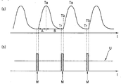
- Figure 5 (a) is a graph showing one breathing cycle of the breathing sensor unit shown in Figure 1
- Figure 5 (b) is a time point when the magnetic resonance image is generated by the magnetic resonance image generating unit shown in FIG. It is a schematic graph.
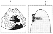
- FIG. 6 is a diagram illustrating an example of an ultrasound image and a magnetic resonance image.
- FIG. 7 is a cross-sectional view schematically showing an ultrasound therapy apparatus according to another embodiment of the present invention.
- FIG. 8 is a flowchart schematically showing a method of driving an ultrasound therapy apparatus according to an embodiment of the present invention.
- the respiratory sensor unit for generating a respiratory detection signal by detecting one respiratory cycle of the subject;
- An information processor extracting a synchronization signal corresponding to any one time period of the one breathing cycle by using the breathing detection signal;
- a magnetic resonance image generating unit including a hollow to which a magnetic field for capturing magnetic resonance images is applied and generating a magnetic resonance image of a region of interest of the object according to the synchronization signal;
- An ultrasound probe generating an ultrasound probe for radiating ultrasound to the ROI of the object, the ultrasound image generator being disposed on one side of the MRI generator to generate an ultrasound image of the ROI;
- an ultrasonic treatment unit disposed at one side of the magnetic resonance image generating unit and configured to irradiate focused ultrasound to the region of interest using the ultrasonic image and the magnetic resonance image.
- the time period may be included in the exhalation period of the one breathing cycle.
- the time period may include a first time point to stop breathing in the respiratory cycle.
- the information processing unit extracts a second time point at which a value calculated by differentiating the respiration detection signal becomes a preset threshold value, and the time period is the first time point and the second time point. It may be a section between.
- the input means for generating an input signal in response to the external periodic input may further include a.
- the information processing unit when the third time point of the input signal is included in the time period, the information processing unit may correspond to the third time point.
- the ultrasound image generating unit and the ultrasound treatment unit may be integrally formed.
- the center of the ultrasound treatment unit may be coincident with the center of the ultrasound probe.
- a moving table which can be moved into the hollow of the magnetic resonance image generating unit may further include.
- the ultrasound image generator and the ultrasound treatment unit may be disposed on the moving table.
- one side is connected to the moving table, it may further include a fixing means for fixing the ultrasound image generating unit and the ultrasound treatment unit disposed on the upper portion of the object.
- the magnetic resonance image and the display unit for displaying the ultrasound image to the outside may further include a.
- One embodiment of the present invention by detecting the respiratory cycle of the subject by the breathing sensor to generate a breathing detection signal; Extracting, by an information processing unit, a synchronization signal corresponding to any one time period of the one breathing cycle using the breathing detection signal; Generating a magnetic resonance image of the ROI of the object according to the synchronization signal by the magnetic resonance image generator; Generating an ultrasound image of the ROI by an ultrasound image generator which includes an ultrasound probe for irradiating ultrasound of the ROI to the ROI of the object and is disposed on one side of the MRI generator; And irradiating focused ultrasound to the region of interest using the ultrasound image and the magnetic resonance image by an ultrasound treatment unit disposed at one side of the magnetic resonance image generating unit. Step and generating the magnetic resonance image is performed at the same time, provides a driving method of the ultrasound therapy apparatus.
- the time period may be included in the exhalation period of the one breathing cycle.
- the time period may include a first time point to stop breathing in the respiratory cycle.
- the extracting of the synchronization signal may include: extracting, by the information processor, a second time point at which a value calculated by differentiating the respiration detection signal becomes a preset threshold; Includes, the time period may be a section between the first time point and the second time point.
- the method may further include generating, by the input means, a periodic input signal in response to an external periodic input.
- the extracting of the synchronization signal may further include: corresponding to the third time point when the third time point at which the input signal is input is included in the time period. can do.
- the display unit may further include displaying the ultrasound image and the magnetic resonance image to the outside.
- An embodiment of the present invention provides a computer program stored in a medium for executing the method of any one of claims 13 to 19 using a computer.
- a part such as a film, a region, a component, or the like is on or on another part, not only is it directly above the other part, but also another film, a region, a component, etc. is interposed therebetween. It also includes cases where there is.
- a film, a region, a component, or the like when a film, a region, a component, or the like is connected, not only the film, the region, and the components are directly connected, but also other films, regions, and components are interposed between the film, the region, and the components. And indirectly connected.
- the film, the region, the component, and the like when the film, the region, the component, and the like are electrically connected, not only the film, the region, the component, and the like are directly electrically connected, but other films, the region, the component, and the like are interposed therebetween. This includes indirect electrical connections.
- FIG. 1 is a perspective view schematically showing an ultrasound therapy apparatus 10 according to an embodiment of the present invention
- Figure 2 is a cross-sectional view taken along the line II-II 'of
- FIG. 3 is a block diagram of the ultrasound therapy apparatus 10 of FIG. 1.
- the ultrasound therapy apparatus 10 includes a magnetic resonance image generator 110, an ultrasound image generator 131, an ultrasound therapy unit 135, and a breathing sensor.
- the unit 120 and the information processing unit 150 is included.
- the ultrasound treatment apparatus 10 may further include a moving table 180, an input unit 190, and a display unit 160.
- the display 160 may display the magnetic resonance image and the ultrasound image to the outside.
- the magnetic resonance image generating unit 110 may include a hollow A to which a magnetic field for magnetic resonance imaging (MRI) is applied.
- the hollow A may have a cylindrical shape with an empty internal space.
- the magnetic resonance image generating unit 110 includes a gantry (gantry) surrounding the hollow (A), the static magnetic field coil 115 and the gradient coil disposed to surround the hollow (A) in the gantry (gantry) 113).
- the static field coil 115 forms a static field in the hollow A, and the gradient coil 113 applies a gradient to the static field to generate a gradient filed.
- the magnetic resonance image generating unit 110 may further include an RF coil (not shown) for applying an RF pulse to the object to excite the atomic nucleus and receive an echo signal from the atomic nucleus.
- FIG 4 is a cross-sectional view schematically showing the ultrasound image generating unit 131 and the ultrasound treatment unit 135 of the ultrasound treatment apparatus 10 according to an embodiment of the present invention.
- the ultrasound image generator 131 includes an ultrasound probe that irradiates an ultrasound image for imaging to a region of interest g of the object P, and is adjacent to the magnetic resonance image generator 110.
- the object P may be a living body of a human or an animal, or an in vivo tissue such as blood vessels, bones, muscles, etc., but is not limited thereto, and the internal structure may be imaged by the ultrasound image generating unit 131. It may be the object (P).
- the ultrasound probe may include at least one transducer, and may transmit an ultrasound signal to the object P, and receive echo ultrasound reflected from the object P using the at least one transducer.
- the ultrasound image generator 131 may generate an ultrasound image by using echo ultrasound.
- the ultrasound treatment unit 135 may be disposed on one side of the magnetic resonance image generating unit 110 and irradiate focused ultrasound to the region of interest g using the ultrasound image and the magnetic resonance image.
- the ultrasound treatment unit 135 may include a hollow frame and a plurality of ultrasonic elements disposed on the inner surface of the hollow frame.
- the hollow frame has a concave hemispherical or flat shape, a plurality of ultrasonic elements are located on the inner surface of the hemispherical or flat hollow frame, the ultrasonic element can irradiate focused ultrasound to the region of interest (g).
- the therapeutic ultrasonic waves can be concentrated on the region of interest g.
- the ultrasound image generator 131 and the ultrasound treatment unit 135 may be integrally formed as shown in FIG. 4. In this case, the integrated ultrasound image generator 131 and the ultrasound treatment unit 135 will be defined as the ultrasound unit 130. In an embodiment, the center of the ultrasound treatment unit 135 may coincide with the center of the ultrasound probe 131. However, the present invention is not limited thereto, and as another embodiment, the center of the ultrasound treatment unit 135 may be different from the center of the ultrasound probe 131.
- the ultrasound treatment apparatus 10 may arrange the magnetic resonance image generating unit 110 and the ultrasonic unit 130 adjacent to each other, and simultaneously perform the ultrasound treatment together with the imaging of the ultrasound image and the magnetic resonance image.
- the ultrasound unit 130 in particular the ultrasound treatment unit 135 may be made of a material (MR compatible) compatible with the magnetic resonance image generating unit 110.
- the ultrasound unit 130 may be made of a nonmagnetic material.
- the ultrasound unit 130 may be made of a material such as reinforced plastic or austenitic cast iron, except for parts that should be electrical or magnetic materials such as connection wirings of ultrasonic elements or driving circuits.
- the ultrasound treatment unit 135 may be compatible with the magnetic resonance image generating unit 110 by using a hydraulic motor instead of an electric motor.
- the present invention is not limited thereto, and may be applied to the ultrasound unit 130 as long as the material or configuration is compatible with the magnetic resonance image generating unit 110.
- the ultrasound therapy apparatus 10 may further include a moving table 180 that may move into the hollow A of the magnetic resonance image generator 110.
- the ultrasound unit 130 including the unit 131 and the ultrasound treatment unit 135 may be disposed on the moving table 180.
- the ultrasound unit 130 may be disposed inside the movement table 180 to face the top surface of the movement table 180.
- the ultrasound treatment unit 135 and the ultrasound image generator 131 may irradiate ultrasound toward the region of interest g of the object P positioned on the upper surface of the movement table 180.
- the moving table 180 may include a treatment table 181 on which the object P is placed, and a guide table 183 for guiding the treatment table 181 to enter or exit into the hollow A.
- the ultrasound treatment unit 135 and the ultrasound image generator 131 may be disposed on the treatment table 181.
- the ultrasound unit 130 may further include a receiving unit (not shown) surrounding the ultrasound treatment unit 135.
- the accommodating part (not shown) may accommodate the coupling liquid for preventing the internal reflection of the ultrasonic part 130 by the reflection coefficient difference.
- the coupling liquid may include a material capable of achieving acoustic coupling, and in one embodiment, may be water. However, the present invention is not limited thereto, and as another embodiment, the coupling liquid may be oil (fat).
- the breathing sensor unit 120 may generate a breathing detection signal by detecting one breathing cycle of the object P.
- the breathing sensor unit 120 may be attached to one region of the object P to detect one breathing cycle.
- the information processor 150 may extract a synchronization signal corresponding to any one time period of one breathing cycle by using the breathing detection signal generated from the breathing sensor 120.
- the magnetic resonance image generator 110 may generate a magnetic resonance image of the region of interest g according to the extracted synchronization signal.
- FIG. 5 (a) is a graph showing one respiratory cycle of the respiratory sensor unit 120 shown in FIG. 1
- Figure 5 (b) is a magnetic resonance image generating unit 110 shown in FIG. It is a graph schematically showing the time point when the resonance image (M) is generated.
- 6 is a view showing an example of the ultrasound image (U) and the magnetic resonance image (M).
- the graph shows the respiratory volume over time.
- the section in which the respiratory rate increases is an inspiration section A, and the section in which the respiratory volume decreases becomes an exhalation section B.
- the magnetic resonance image generating unit 110 may photograph when the region of interest g does not move. In other words, the magnetic resonance image generating unit 110 may take a magnetic resonance image (M) when the breathing stops.
- the magnetic resonance image It may be provided to the generation unit 110.
- the time period may be included in the expiration period (B) of one breathing cycle.
- Exhalation section (B) is longer than the inhalation section (A) is a breathing stop longer, the magnetic resonance image generating unit 110 can be stably photographed the magnetic resonance image (M) in the exhalation section (B).
- the present invention is not limited to this.
- the time period may include a first time point at which breathing stops during the breathing cycle.
- a time point at which breathing stops during one respiration cycle is a first-first time point Ta in the inspiration period A and a first-second time point Tb in the exhalation period B.
- the first time point may correspond to the 1-2 time point (Tb).
- the information processor 150 may extract a second time point Tr at which a value calculated by differentiating the respiration detection signal becomes a preset threshold.
- the information processor 150 may calculate a slope for each time point by differentiating a respiration detection signal representing a respiration volume over time. In this case, when the slope is 0, it may be determined as the time when the breathing stops.
- a threshold value close to zero may be set in advance and stored in the information processing unit 150.
- the information processing unit 150 may extract a second time point Tr when the value calculated by differentiating the respiration detection signal becomes the threshold value, and then define a section between the first time point and the second time point as a time period. . Accordingly, the magnetic resonance image generating unit 110 may generate and generate the magnetic resonance image M between the first time point Tb and the second time point Tr during one breathing cycle. In this case, the ultrasound image generator 131 may continuously generate an ultrasound image of the region of interest g, and the magnetic resonance image M may intermittently generate the magnetic resonance image M of the region of interest g. .
- the ultrasound therapy apparatus 10 may provide an ultrasound image U and a magnetic resonance image M in real time, and through the region of interest ( g) accurate position tracking and temperature measurement are possible, so that stable ultrasound treatment is possible.
- the ultrasound therapy apparatus 10 may further include an input unit 190 (refer to FIG. 3) for generating an input signal in response to an external periodic input.
- the input means 190 may include a button that the object P can press at the time when the breathing stops.
- the information processor 150 determines a time period including a time point at which breathing stops using the breathing detection signal generated from the breathing sensor unit 120.
- the ultrasound treatment apparatus 10 of another embodiment may further include an input means 190 to extract the exact respiratory stop time input from the object (P). have.
- the ultrasound treatment apparatus 10 may further include a guide means (not shown) for recognizing and inputting an accurate respiration stop time through the respiration education of the object (P).
- the guide means may be a lighting that can be visually recognized by the object P or a speaker that can be audibly recognized.
- the object (P) is able to press the button at the point where the breathing stops exactly through the breathing training using the guide means.
- the information processor 150 may determine whether the third time point at which the input signal is generated is included in the time period, and, when included, may correspond to the third time point. In other words, the information processor 150 may generate a synchronization signal to capture the magnetic resonance image M at the third time point at which the breathing stops.
- FIG. 7 is a schematic cross-sectional view of an ultrasound therapy apparatus 20 according to another exemplary embodiment
- FIG. 8 is a schematic cross-sectional view of an ultrasound therapy apparatus 30 according to another embodiment.
- Other embodiments of the present invention and the other embodiments are the same as the ultrasound treatment apparatus according to an embodiment except for the arrangement position of the ultrasound unit, duplicate description will be omitted.
- the ultrasound treatment apparatus 20 may further include fixing means 237 for fixing the ultrasound image generator (not shown) and the ultrasound treatment unit 235.
- the fixing means 237 may be fixed so that one side is connected to the moving table 180 and the ultrasound image generator and the ultrasound treatment unit 235 are disposed on the object P.
- the region of interest g may be a tumor of an organ located in the abdomen, such as the liver and the kidney.
- FIG. 8 is a flow chart schematically showing a method of driving the ultrasound therapy apparatus 10 according to an embodiment of the present invention.
- the ultrasound image generator 131 includes an ultrasound probe for irradiating an ultrasound image for imaging to a region of interest g of the object P, and continuously performs an ultrasound image of the region of interest g during treatment. To generate (S1).
- the breathing sensor 120 detects one breathing cycle of the object (P) generates a breathing detection signal (S2). Thereafter, the information processing unit 150 extracts a synchronization signal corresponding to any one time period of one breathing cycle using the breathing detection signal (S3), and the magnetic resonance image generating unit 110 generates a region of interest according to the synchronization signal ( Generate a magnetic resonance image of g) (S4).
- the information processor 150 may extract a first time point at which breathing stops and a second time point at which a value calculated by differentiating the respiration detection signal becomes a preset threshold value among the respiration detection signals.
- the time section is a section between the first time point and the second time point.
- the information processing unit 150 provides a synchronization signal corresponding to the time period to the magnetic resonance image generation unit 110, and the magnetic resonance image generation unit 110 intermittently generates the magnetic resonance image at a time corresponding to the time period during the respiration cycle. Shoot and create.
- a detailed method of generating the synchronization signal by the information processing unit 150 has been described above, overlapping description will be omitted.
- Generating the magnetic resonance image (S4) is performed simultaneously with generating the ultrasound image (S1), the continuous ultrasound image and the intermittent magnetic resonance image is provided to the ultrasound treatment unit 135. Thereafter, the ultrasound treatment unit 135 irradiates the focused ultrasound to the region of interest g using the magnetic resonance image and the ultrasound image (S5).
- the ultrasound treatment apparatus and its driving method by taking a magnetic resonance image (M) in accordance with the synchronization signal corresponding to the point of stopping the breathing through the breathing sensor unit and the information processing unit, Ultrasonic image (U) and magnetic resonance image (M) can be provided in real time, and through this, accurate position tracking and temperature measurement of the region of interest (g) is possible and thus stable ultrasound treatment is possible.
- M magnetic resonance image
- Embodiments according to the present invention described above may be implemented in the form of a computer program that can be executed through various components on a computer, such a computer program may be recorded on a computer readable medium.
- the media may be magnetic media such as hard disks, floppy disks and magnetic tape, optical recording media such as CD-ROMs and DVDs, magneto-optical media such as floptical disks, and ROMs.
- Hardware devices specifically configured to store and execute program instructions such as memory, RAM, flash memory, and the like.
- the medium may include an intangible medium that is implemented in a form that can be transmitted on a network.
- the medium may be a medium that may be implemented in the form of a software or an application to be transmitted and distributed through a network.
- the computer program is specifically designed and configured for the present invention, but may be known and available to those skilled in the computer software field.
- Examples of computer programs may include not only machine code generated by a compiler, but also high-level language code executable by a computer using an interpreter or the like.
- connection or connection members of the lines between the components shown in the drawings by way of example shows a functional connection and / or physical or circuit connections, in the actual device replaceable or additional various functional connections, physical It may be represented as a connection, or circuit connections.
- such as "essential”, “important” may not be a necessary component for the application of the present invention.
- an ultrasound therapy apparatus and a driving method thereof are provided.
- embodiments of the present invention can be applied to the tracking of tumor location used in the industry.
Landscapes
- Health & Medical Sciences (AREA)
- Life Sciences & Earth Sciences (AREA)
- Nuclear Medicine, Radiotherapy & Molecular Imaging (AREA)
- Physics & Mathematics (AREA)
- Biomedical Technology (AREA)
- Animal Behavior & Ethology (AREA)
- General Health & Medical Sciences (AREA)
- Public Health (AREA)
- Veterinary Medicine (AREA)
- Engineering & Computer Science (AREA)
- Radiology & Medical Imaging (AREA)
- Pathology (AREA)
- Biophysics (AREA)
- Heart & Thoracic Surgery (AREA)
- Medical Informatics (AREA)
- Molecular Biology (AREA)
- Surgery (AREA)
- High Energy & Nuclear Physics (AREA)
- Pulmonology (AREA)
- Physiology (AREA)
- Magnetic Resonance Imaging Apparatus (AREA)
- Surgical Instruments (AREA)
Abstract
본 발명의 일 실시예는, 대상체의 일 호흡주기를 감지하여 호흡감지신호를 생성하는 호흡센서부; 상기 호흡감지신호를 이용하여 상기 일 호흡주기 중 어느 하나의 시구간에 대응되는 동기화 신호를 추출하는 정보처리부; 자기공명영상 촬영을 위한 자기장이 인가되는 중공을 포함하고, 상기 동기화 신호에 따라 상기 대상체의 관심영역의 자기공명영상을 생성하는 자기공명영상 생성부; 상기 대상체의 관심영역에 촬상용 초음파를 조사시키는 초음파 프로브(probe)를 포함하며, 상기 자기공명영상 생성부의 일 측에 배치되어 상기 관심영역의 초음파 영상을 생성하는 초음파영상 생성부; 및 상기 자기공명영상 생성부의 일 측에 배치되며, 상기 초음파영상 및 상기 자기공명영상을 이용하여 상기 관심영역에 집속(focused) 초음파를 조사하는 초음파 치료부;를 포함하는, 초음파 치료 장치를 제공한다.
Description
본 발명의 실시예들은 초음파 치료 장치 및 이의 구동 방법에 관한 것으로서, 보다 상세하게는 종양의 정확한 위치 추적이 가능한 초음파 치료 장치 및 이의 구동 방법에 관한 것이다.
고강도 집속 초음파(High-Intensity focused ultrasound; HIFU) 치료는 비침습적(non-invasive)이고 또한, 비손상(non-traumatic)적으로 접근하는 치료법이다. 이것은 특히 종양(tumor)을 가진 환자에게 적용된다. 종래의 외과적 처리 또는 화학적 요법과 비교하여서, HIFU 치료는 환자에게 외상을 덜 주고, 따라서 이것의 적용은 빠르게 증가하고 있다. 이러한 징후는 간암(liver cancer), 골 육종(bone sarcoma), 유방암(breast cancer), 췌장암(pancreas cancer), 신장암(kidney cancer), 연조직의 종양(soft tissue tumor) 및 골반 종양(pelvic tumor)을 포함한다.
대부분의 HIFU 치료는 대상 종양을 관심 영역에 위치시키고 치료를 모니터하기 위한 초음파 영상 장치를 사용한다. 초음파 영상 장치는 진단하고자 하는 대상체를 향하여 초음파를 송신하고 반사된 초음파로부터 대상체의 영상을 형성하여 표시하는 장치로서 인체 조직의 반사계수를 이용하는 B-모드(brightness-mode)로서 많이 표현된다.
한편, 일부 HIFU 치료는 자기공명영상(MRI)을 이와 같은 목적으로 사용하는데, MRI는 조직 간의 자기적 이완의 정도로부터 정보를 얻어서 영상을 시각화한다. MRI는 체내 구조물의 사진을 생성하기 위해서 자기장을 사용하는 진단 기술로서, 인체 내의 수소 원자가 자기장 및 전자파와 반응하는 방식을 근거로 영상을 생성한다. 상기의 원리를 기반으로 MRI는 뇌, 척수, 심장, 안구, 간, 췌장, 신장, 유방 및 전립선 같은 신체의 연부조직 종양을 발견하고 질환을 검사하는데 사용된다. 다만, MRI는 소작 범위의 온도측정이 가능한 유일한 영상기법인데 반해, 장기의 운동 혹은 장 내 공기로 인하여 허상에 취약한 문제점이 있다.
이러한 문제점을 해결하기 위하여, 본 발명의 실시예들은 호흡주기에 동기화된 신호를 이용하여 자기공명영상을 생성함으로써, 움직이는 장기에 생긴 종양의 정확한 위치 추적이 가능한 초음파 치료 장치 및 이의 구동방법을 제공하고자 한다.
본 발명의 일 실시예는, 대상체의 일 호흡주기를 감지하여 호흡감지신호를 생성하는 호흡센서부, 상기 호흡감지신호를 이용하여 상기 일 호흡주기 중 어느 하나의 시구간에 대응되는 동기화 신호를 추출하는 정보처리부, 자기공명영상 촬영을 위한 자기장이 인가되는 중공을 포함하고, 상기 동기화 신호에 따라 상기 대상체의 관심영역의 자기공명영상을 생성하는 자기공명영상 생성부, 상기 대상체의 관심영역에 촬상용 초음파를 조사시키는 초음파 프로브(probe)를 포함하며, 상기 자기공명영상 생성부의 일 측에 배치되어 상기 관심영역의 초음파 영상을 생성하는 초음파영상 생성부 및 상기 자기공명영상 생성부의 일 측에 배치되며, 상기 초음파영상 및 상기 자기공명영상을 이용하여 상기 관심영역에 집속(focused) 초음파를 조사하는 초음파 치료부를 포함하는, 초음파 치료 장치를 제공한다.
본 발명의 실시예들에 따른 초음파 치료 장치 및 이의 구동 방법은 호흡센서부 및 정보처리부를 통해 호흡이 멈추는 시점에 대응되는 동기화 신호에 따라 자기공명영상을 촬영함으로써, 실시간으로 초음파영상 및 자기공명영상을 제공할 수 있고, 이를 통해 관심영역의 정확한 위치 추적 및 온도 측정이 가능하여 안정적인 초음파 치료가 가능하게 된다.
도 1은 본 발명의 일 실시예에 따른 초음파 치료 장치를 개략적으로 도시한 사시도이다.
도 2는 도 1의 Ⅱ-Ⅱ'선을 따라 절취하여 도시한 단면도이다.
도 3은 도 1의 초음파 치료 장치의 블록도이다.
도 4는 본 발명의 일 실시예에 따른 초음파 치료 장치의 초음파영상 생성부 및 초음파 치료부를 개략적으로 도시한 단면도이다.
도 5의 (a)는 도 1에 도시된 호흡센서부의 일 호흡주기를 나타낸 그래프이고, 도 5의 (b)는 도 1에 도시된 자기공명영상 생성부에 의해 자기공명영상이 생성되는 시점을 개략적으로 나타낸 그래프이다.
도 6은 초음파영상 및 자기공명영상의 일례를 나타낸 도면이다.
도 7은 본 발명의 다른 실시예에 따른 초음파 치료 장치를 개략적으로 나타낸 단면도이다.
도 8 본 발명의 일 실시예에 따른 초음파 치료 장치의 구동방법을 개략적으로 나타낸 순서도이다.
본 발명의 일 실시예는, 대상체의 일 호흡주기를 감지하여 호흡감지신호를 생성하는 호흡센서부; 상기 호흡감지신호를 이용하여 상기 일 호흡주기 중 어느 하나의 시구간에 대응되는 동기화 신호를 추출하는 정보처리부; 자기공명영상 촬영을 위한 자기장이 인가되는 중공을 포함하고, 상기 동기화 신호에 따라 상기 대상체의 관심영역의 자기공명영상을 생성하는 자기공명영상 생성부; 상기 대상체의 관심영역에 촬상용 초음파를 조사시키는 초음파 프로브(probe)를 포함하며, 상기 자기공명영상 생성부의 일 측에 배치되어 상기 관심영역의 초음파 영상을 생성하는 초음파영상 생성부; 및 상기 자기공명영상 생성부의 일 측에 배치되며, 상기 초음파영상 및 상기 자기공명영상을 이용하여 상기 관심영역에 집속(focused) 초음파를 조사하는 초음파 치료부;를 포함하는, 초음파 치료 장치를 제공한다.
본 발명의 일 실시예에 있어서, 상기 시구간은 상기 일 호흡주기 중 호기 구간에 포함될 수 있다.
본 발명의 일 실시예에 있어서, 상기 시구간은 상기 호흡주기 중 호흡이 멈추는 제1시점을 포함할 수 있다.
본 발명의 일 실시예에 있어서, 상기 정보처리부는 상기 호흡감지신호를 미분하여 산출된 값이 사전에 설정된 임계값이 되는 제2시점을 추출하고, 상기 시구간은 상기 제1시점과 제2시점의 사이 구간일 수 있다.
본 발명의 일 실시예에 있어서, 외부의 주기적인 입력에 대응하여 입력신호를 생성하는 입력수단;을 더 포함할 수 있다.
본 발명의 일 실시예에 있어서, 상기 정보처리부는 상기 입력신호의 제3시점이 상기 시구간 내에 포함되는 경우, 상기 동기화 신호를 상기 제3시점에 대응시킬 수 있다.
본 발명의 일 실시예에 있어서, 상기 초음파영상 생성부 및 상기 초음파 치료부는 일체로 형성될 수 있다.
본 발명의 일 실시예에 있어서, 상기 초음파 치료부의 중심(center)은 상기 초음파 프로브의 중심과 일치할 수 있다.
본 발명의 일 실시예에 있어서, 상기 자기공명영상 생성부의 중공 내로 이동이 가능한 이동 테이블;을 더 포함할 수 있다.
본 발명의 일 실시예에 있어서, 상기 초음파영상 생성부 및 상기 초음파 치료부는 상기 이동 테이블에 배치될 수 있다.
본 발명의 일 실시예에 있어서, 일측이 상기 이동테이블에 연결되고, 상기 초음파영상 생성부 및 상기 초음파 치료부가 상기 대상체의 상부에 배치되도록 고정하는 고정수단을 더 포함할 수 있다.
본 발명의 일 실시예에 있어서, 상기 자기공명영상 및 상기 초음파영상을 외부로 표시하는 디스플레이부;를 더 포함할 수 있다.
본 발명의 일 실시예는, 호흡센서부에 의해, 대상체의 일 호흡주기를 감지하여 호흡감지신호를 생성하는 단계; 정보처리부에 의해, 상기 호흡감지신호를 이용하여 상기 일 호흡주기 중 어느 하나의 시구간에 대응되는 동기화 신호를 추출하는 단계; 자기공명영상 생성부에 의해, 상기 동기화 신호에 따라 상기 대상체의 관심영역의 자기공명영상을 생성하는 단계; 상기 대상체의 관심영역에 촬상용 초음파를 조사시키는 초음파 프로브를 포함하며 상기 자기공명영상 생성부의 일측에 배치되는 초음파영상 생성부에 의해, 상기 관심영역의 초음파 영상을 생성하는 단계; 및 상기 자기공명영상 생성부의 일 측에 배치되는 초음파 치료부에 의해, 상기 초음파 영상 및 상기 자기공명영상을 이용하여 상기 관심영역에 집속 초음파를 조사하는 단계;를 포함하고, 상기 초음파영상을 생성하는 단계 및 상기 자기공명영상을 생성하는 단계는 동시에 수행되는, 초음파 치료 장치의 구동 방법을 제공한다.
본 발명의 일 실시예에 있어서, 상기 시구간은 상기 일 호흡주기 중 호기 구간에 포함될 수 있다.
본 발명의 일 실시예에 있어서, 상기 시구간은 상기 호흡주기 중 호흡이 멈추는 제1시점을 포함할 수 있다.
본 발명의 일 실시예에 있어서, 상기 동기화 신호를 추출하는 단계는, 상기 정보처리부에 의해, 상기 호흡감지신호를 미분하여 산출된 값이 사전에 설정된 임계값이 되는 제2시점을 추출하는 단계;를 포함하고, 상기 시구간은 상기 제1시점과 상기 제2시점의 사이 구간일 수 있다.
본 발명의 일 실시예에 있어서, 입력수단에 의해, 외부의 주기적인 입력에 대응하여 주기적인 입력신호를 생성하는 단계;를 더 포함할 수 있다.
본 발명의 일 실시예에 있어서, 상기 동기화 신호를 추출하는 단계는, 상기 입력신호이 입력되는 제3시점이 상기 시구간 내에 포함되는 경우, 상기 동기화 신호를 제3시점에 대응시키는 단계;를 더 포함할 수 있다.
본 발명의 일 실시예에 있어서, 디스플레이부에 의해, 상기 초음파영상 및 상기 자기공명영상을 외부로 표시하는 단계;를 더 포함할 수 있다.
본 발명의 일 실시예는, 컴퓨터를 이용하여 제13항 내지 제19항 중 어느 하나의 방법을 실행시키기 위하여 매체에 저장된 컴퓨터 프로그램을 제공한다.
전술한 것 외의 다른 측면, 특징, 이점이 이하의 도면, 특허청구범위 및 발명의 상세한 설명으로부터 명확해질 것이다.
본 발명은 다양한 변환을 가할 수 있고 여러 가지 실시예를 가질 수 있는 바, 특정 실시예들을 도면에 예시하고 상세한 설명에 상세하게 설명하고자 한다. 본 발명의 효과 및 특징, 그리고 그것들을 달성하는 방법은 도면과 함께 상세하게 후술되어 있는 실시예들을 참조하면 명확해질 것이다. 그러나 본 발명은 이하에서 개시되는 실시예들에 한정되는 것이 아니라 다양한 형태로 구현될 수 있다.
이하, 첨부된 도면을 참조하여 본 발명의 실시예들을 상세히 설명하기로 하며, 도면을 참조하여 설명할 때 동일하거나 대응하는 구성 요소는 동일한 도면부호를 부여하고 이에 대한 중복되는 설명은 생략하기로 한다.
이하의 실시예에서, 제1, 제2 등의 용어는 한정적인 의미가 아니라 하나의 구성 요소를 다른 구성 요소와 구별하는 목적으로 사용되었다.
이하의 실시예에서, 단수의 표현은 문맥상 명백하게 다르게 뜻하지 않는 한, 복수의 표현을 포함한다.
이하의 실시예에서, 포함하다 또는 가지다 등의 용어는 명세서상에 기재된 특징, 또는 구성요소가 존재함을 의미하는 것이고, 하나 이상의 다른 특징들 또는 구성요소가 부가될 가능성을 미리 배제하는 것은 아니다.
이하의 실시예에서, 막, 영역, 구성 요소 등의 부분이 다른 부분 위에 또는 상에 있다고 할 때, 다른 부분의 바로 위에 있는 경우뿐만 아니라, 그 중간에 다른 막, 영역, 구성 요소 등이 개재되어 있는 경우도 포함한다.
도면에서는 설명의 편의를 위하여 구성 요소들이 그 크기가 과장 또는 축소될 수 있다. 예컨대, 도면에서 나타난 각 구성의 크기 및 두께는 설명의 편의를 위해 임의로 나타내었으므로, 본 발명이 반드시 도시된 바에 한정되지 않는다.
어떤 실시예가 달리 구현 가능한 경우에 특정한 공정 순서는 설명되는 순서와 다르게 수행될 수도 있다. 예를 들어, 연속하여 설명되는 두 공정이 실질적으로 동시에 수행될 수도 있고, 설명되는 순서와 반대의 순서로 진행될 수 있다.
이하의 실시예에서, 막, 영역, 구성 요소 등이 연결되었다고 할 때, 막, 영역, 구성 요소들이 직접적으로 연결된 경우뿐만 아니라 막, 영역, 구성요소들 중간에 다른 막, 영역, 구성 요소들이 개재되어 간접적으로 연결된 경우도 포함한다. 예컨대, 본 명세서에서 막, 영역, 구성 요소 등이 전기적으로 연결되었다고 할 때, 막, 영역, 구성 요소 등이 직접 전기적으로 연결된 경우뿐만 아니라, 그 중간에 다른 막, 영역, 구성 요소 등이 개재되어 간접적으로 전기적 연결된 경우도 포함한다.
도 1은 본 발명의 일 실시예에 따른 초음파 치료 장치(10)를 개략적으로 도시한 사시도이고, 도 2는 도 1의 Ⅱ-Ⅱ'선을 따라 절취하여 도시한 단면도이다. 도 3은 도 1의 초음파 치료 장치(10)의 블록도이다.
도 1 내지 도 3을 참조하면, 본 발명의 일 실시예에 따른 초음파 치료 장치(10)는 자기공명영상 생성부(110), 초음파영상 생성부(131), 초음파 치료부(135), 호흡센서부(120) 및 정보처리부(150)를 포함한다. 또한, 초음파 치료 장치(10)는 이동테이블(180), 입력수단(190) 및 디스플레이부(160)를 더 포함할 수 있다. 여기서, 디스플레이부(160)는 자기공명영상 및 초음파영상을 외부로 표시할 수 있다.
자기공명영상 생성부(110)는 자기공명영상(Magnetic resonance imaging; MRI) 촬영을 위한 자기장이 인가되는 중공(A)을 포함할 수 있다. 중공(A)은 내부 공간이 비어있는 원통형의 형상일 수 있다. 자기공명영상 생성부(110)는 중공(A)을 둘러싸는 갠트리(gantry)를 포함하며, 갠트리(gantry) 내부에 이러한 중공(A)을 둘러싸도록 배치되는 정자장 코일(115) 및 경사 코일(113)을 포함할 수 있다. 정자장 코일(115)은 중공(A)에 정자장(static field)를 형성하며, 경사 코일(113)은 정자장에 경사(gradient)를 인가하여 경사자장(gradient filed)을 발생시킨다. 또한, 도시하지 않았지만, 자기공명영상 생성부(110)는 대상체에 RF 펄스를 인가하여 원자핵을 여기시키고 원자핵으로부터 에코 신호를 수신하는 RF 코일(미도시)을 더 포함할 수 있다.
도 4는 본 발명의 일 실시예에 따른 초음파 치료 장치(10)의 초음파영상 생성부(131) 및 초음파 치료부(135)를 개략적으로 도시한 단면도이다.
도 4를 참조하면, 초음파영상 생성부(131)는 대상체(P)의 관심영역(g)에 촬상용 초음파를 조사시키는 초음파 프로브(probe)를 포함하며, 자기공명영상 생성부(110)에 인접하여 배치될 수 있다. 여기서, 대상체(P)는 인간이나 동물의 생체, 또는 혈관, 뼈, 근육 등과 같은 생체 내 조직일 수도 있으나 이에 한정되지 않으며, 초음파영상 생성부(131)에 의해 그 내부 구조가 영상화 될 수 있는 것이라면 대상체(P)가 될 수 있다. 초음파 프로브는 적어도 하나의 트랜스듀서(transducer)를 포함하고, 이를 이용하여 초음파 신호를 대상체(P)로 송신하고, 대상체(P)로부터 반사된 에코(echo) 초음파를 수신할 수 있다. 초음파영상 생성부(131)는 에코 초음파를 이용하여 초음파영상을 생성할 수 있다.
초음파 치료부(135)는 자기공명영상 생성부(110)의 일 측에 배치되며, 초음파영상 및 자기공명영상을 이용하여 관심영역(g)에 집속(focused) 초음파를 조사할 수 있다. 초음파 치료부(135)는 중공프레임 및 중공프레임 내측면에 배치되는 복수개의 초음파소자를 포함할 수 있다. 중공프레임은 오목한 반구형상 또는 편평한 형상을 가지며, 반구형상 또는 편평한 형상의 중공프레임의 내측면에는 복수개의 초음파 소자가 위치하고, 초음파 소자는 관심영역(g)으로 집속 초음파를 조사할 수 있다. 반구형상의 중공 프레임 내측면에 초음파 소자가 복수개 위치함으로써 치료용 초음파를 관심 영역(g)에 집중적으로 조사할 수 있다.
초음파영상 생성부(131) 및 초음파 치료부(135)는 도 4에 도시된 바와 같이 일체로 형성될 수 있다. 이때, 일체의 초음파영상 생성부(131) 및 초음파 치료부(135)를 초음파부(130)로 정의하기로 한다. 일 실시예로서, 초음파 치료부(135)의 중심(center)은 초음파 프로브(131)의 중심과 일치할 수 있다. 그러나, 본 발명은 이에 한정되지 않으며, 다른 실시예로서, 초음파 치료부(135)의 중심은 초음파 프로브(131)의 중심과 다를 수 있다.
한편, 초음파 치료 장치(10)는 자기공명영상 생성부(110) 및 초음파부(130)를 인접하게 배치하여, 초음파영상 및 자기공명영상을 촬영과 함께 초음파 치료를 동시에 수행할 수 있다. 이때, 초음파부(130), 특히 초음파 치료부(135)는 자기공명영상 생성부(110)와 양립할 수 있는(MR compatible) 재질로 이루어질 수 있다. 구체적으로 초음파부(130)는 비자성체로 이루어질 수 있다. 예를 들면, 초음파부(130)는 초음파 소자 또는 구동회로의 연결배선과 같이 전기적이거나 자성체가 아니면 안되는 부분을 제외하고 강화플라스틱 또는 오스테나이트 주철과 같은 재질로 이루어질 수 있다. 또한, 초음파 치료부(135)는 전기적 모터가 아닌 유압식 모터를 사용하는 것에 의해 자기공명영상 생성부(110)와 양립될 수 있다. 그러나 본 발명은 이에 한정되지 않으며, 자기공명영상 생성부(110)와 양립할 수 있는 재질 또는 구성이면 초음파부(130)에 적용이 가능하다.
계속해서 도 1 내지 도 4를 참조하면, 초음파 치료 장치(10)는 자기공명영상 생성부(110)의 중공(A) 내로 이동이 가능한 이동 테이블(180)을 더 포함할 수 있는데, 초음파영상 생성부(131) 및 초음파 치료부(135)를 포함하는 초음파부(130)는 이동 테이블(180)에 배치될 수 있다. 일 실시예로서, 초음파부(130)는 이동 테이블(180)의 상면을 바라보도록 이동 테이블(180)의 내부에 배치될 수 있다. 이때, 초음파 치료부(135) 및 초음파영상 생성부(131)는 이동 테이블(180)의 상면에 위치하는 대상체(P)의 관심영역(g)을 향하여 초음파를 조사할 수 있다. 또한, 이동테이블(180)은 대상체(P)가 놓이는 치료대(181) 및 치료대(181)를 중공(A) 내로 진입 또는 진출할 수 있도록 안내하는 가이드대(183)를 포함할 수 있다. 이 경우, 초음파 치료부(135) 및 초음파영상 생성부(131)는 치료대(181)에 배치될 수 있다.
초음파부(130)는 도시하지 않았지만, 초음파부(130)는 초음파 치료부(135)를 감싸는 수용부(미도시)를 더 포함할 수 있다. 수용부(미도시)는 내부에 초음파부(130)가 접촉되는 표면의 반사계수 차이에 의해 반사되는 것을 막기 위한 커플링액을 수용할 수 있다. 커플링액은 음향결합(acoustic coupling)을 이룰 수 있는 물질을 포함할 수 있으며, 일 실시예로서, 물 일 수 있다. 그러나, 본 발명은 이에 한정되지 않으며, 다른 실시예로서, 커플링액은 기름(지방)일 수 있다.
호흡센서부(120)는 대상체(P)의 일 호흡주기를 감지하여 호흡감지신호를 생성할 수 있다. 호흡센서부(120)는 대상체(P)의 일 영역에 부착되어 일 호흡주기를 감지할 수 있다.
정보처리부(150)는 상기 호흡센서부(120)로부터 생성된 호흡감지신호를 이용하여 일 호흡주기 중 어느 하나의 시구간에 대응되는 동기화 신호를 추출할 수 있다. 자기공명영상 생성부(110)는 추출된 상기 동기화 신호에 따라 관심영역(g)의 자기공명영상을 생성할 수 있다.
도 5의 (a)는 도 1에 도시된 호흡센서부(120)의 일 호흡주기를 나타낸 그래프이고, 도 5의 (b)는 도 1에 도시된 자기공명영상 생성부(110)에 의해 자기공명영상(M)이 생성되는 시점을 개략적으로 나타낸 그래프이다. 도 6은 초음파영상(U) 및 자기공명영상(M)의 일례를 나타낸 도면이다.
도 5의 (a) 및 (b)를 참조하면, 그래프는 시간에 따른 호흡량을 나타낸다. 호흡량이 늘어나는 구간은 흡기 구간(A)이며, 호흡량이 줄어드는 구간은 호기 구간(B)이 된다. 자기공명영상 생성부(110)는 관심영역(g)이 움직이지 않는 경우에 촬영이 가능하다. 다시 말해, 자기공명영상 생성부(110)는 호흡이 멈추는 때에 자기공영명상(M)을 촬영할 수 있다.
정보처리부(150)는 호흡센서부(120)로부터 제공받은 호흡감지신호를 이용하여 호흡이 멈추는 때, 다시 말해, 일 호흡주기 중 어느 하나의 시구간에 대응되는 동기화 신호를 생성한 후, 자기공명영상 생성부(110)로 제공할 수 있다. 상기 시구간은 일 호흡주기 중 호기 구간(B)에 포함될 수 있다. 호기 구간(B)은 흡기 구간(A)에 비해 호흡이 멈추는 구간이 길어, 자기공명영상 생성부(110)는 호기 구간(B)에서 자기공명영상(M)을 안정적으로 촬영할 수 있다. 그러나, 본 발명은 이에 한정되지 않는다.
시구간은 호흡주기 중 호흡이 멈추는 제1시점을 포함할 수 있다. 도 5를 참조하면, 일 호흡주기 중 호흡이 멈추는 시점은 흡기 구간(A) 중 제1-1시점(Ta) 및 호기 구간(B) 중 제1-2시점(Tb)이다. 다만, 시구간이 호기 구간(B)에 포함되는 경우, 제1시점은 제1-2시점(Tb)에 대응될 수 있다.
한편, 정보처리부(150)는 상기 호흡감지신호를 미분하여 산출된 값이 사전에 설정된 임계값이 되는 제2시점(Tr)을 추출할 수 있다. 구체적으로, 정보처리부(150)는 시간에 따른 호흡량을 나타내는 호흡감지신호를 미분함으로써 각 시점에 대한 기울기를 산출할 수 있다. 이때, 기울기가 0인 경우, 호흡이 멈추는 시점으로 판단할 수 있다. 다만, 주기적인 호흡주기에서 호흡감지신호의 미분기울기가 완전히 0이 되는 것은 불가능한 경우도 있으므로, 0에 가까운 임계값을 사전에 설정하여 정보처리부(150)에 저장할 수 있다. 정보처리부(150)는 호흡감지신호를 미분하여 산출된 값이 상기 임계값이 되는 경우의 제2시점(Tr)을 추출한 후, 제1시점과 제2시점 사이 구간을 시구간으로 정의할 수 있다. 따라서, 자기공명영상 생성부(110)는 일 호흡주기 중 제1시점(Tb)과 제2시점(Tr) 사이에 자기공명영상(M)을 촬영하여 생성할 수 있다. 이때, 초음파영상 생성부(131)는 관심영역(g)의 초음파영상을 계속적으로 생성하며, 자기공명영상(M)은 관심영역(g)의 자기공명영상(M)을 간헐적으로 생성할 수 있다. 그러나, 이러한 생성 과정은 동시에 수행되므로, 본 발명의 일 실시예에 따른 초음파 치료 장치(10)는 실시간으로 초음파영상(U) 및 자기공명영상(M)을 제공할 수 있고, 이를 통해 관심영역(g)의 정확한 위치 추적 및 온도 측정이 가능하여 안정적인 초음파 치료가 가능하게 된다.
다른 실시예로서, 초음파 치료 장치(10)는 외부의 주기적인 입력에 대응하여 입력신호를 생성하는 입력수단(190, 도 3 참조)을 더 포함할 수 있다. 입력수단(190)은 호흡이 멈추는 시점에 대상체(P)가 누를 수 있는 버튼을 포함할 수 있다. 일 실시예의 정보처리부(150)는 호흡센서부(120)로부터 생성된 호흡감지신호를 이용하여 호흡이 멈추는 시점을 포함하는 시구간을 판단한다. 다만, 호흡센서부(120)의 측정오차를 최소화하기 위하여, 다른 실시예의 초음파 치료 장치(10)는 입력수단(190)을 더 포함하여 대상체(P)로부터 입력되는 정확한 호흡멈춤시점을 추출할 수 있다.
이때, 초음파 치료 장치(10)는 대상체(P)의 호흡교육을 통해 정확한 호흡멈춤시점을 인지하여 입력하도록 하는 가이드수단(미도시)을 더 포함할 수 있다. 예를 들면, 가이드수단은 대상체(P)가 시각적으로 인지할 수 있는 조명 또는 청각적으로 인지할 수 있는 스피커일 수 있다. 대상체(P)는 가이드수단을 이용한 호흡교육을 통해 호흡이 정확히 멈춘 시점에 버튼을 누를 수 있게 된다. 정보처리부(150)는 입력신호가 생성되는 제3시점이 시구간 내에 포함되는지를 판단하고, 포함되는 경우에 동기화 신호를 제3시점에 대응시킬 수 있다. 다시 말해, 정보처리부(150)는 호흡이 멈추는 정확한 시점인 제3시점에 자기공명영상(M)을 촬영하도록 동기화 신호를 생성할 수 있다.
도 7은 본 발명의 다른 실시예에 따른 초음파 치료 장치(20)를 개략적으로 나타낸 단면도이고, 도 8은 또 다른 실시예에 따른 초음파 치료 장치(30)를 개략적으로 나타낸 단면도이다. 본 발명의 다른 실시예 및 또 다른 실시예는 초음파부의 배치 위치를 제외하고, 일 실시예에 따른 초음파 치료 장치와 구성요소가 동일하므로, 중복되는 설명은 생략하기로 한다.
도 7을 참조하면, 다른 실시예에 따른 초음파 치료 장치(20)는 초음파영상 생성부(미도시) 및 초음파 치료부(235)를 고정시키는 고정수단(237)을 더 포함할 수 있다. 고정수단(237)은 일측이 이동테이블(180)에 연결되고, 초음파영상 생성부 및 초음파 치료부(235)가 대상체(P)의 상부에 배치되도록 고정할 수 있다. 이때, 관심영역(g)은 간, 신장 등과 같이 복부에 위치하는 장기의 종양일 수 있다.
도 8은 본 발명의 일 실시예에 따른 초음파 치료 장치(10)의 구동방법을 개략적으로 나타낸 순서도이다.
도 8을 참조하면, 초음파영상 생성부(131)는 대상체(P)의 관심영역(g)에 촬상용 초음파를 조사시키는 초음파 프로브를 포함하고, 치료하는 동안 계속적으로 관심영역(g)의 초음파영상을 생성한다(S1).
한편, 호흡센서부(120)는 대상체(P)의 일 호흡주기를 감지하여 호흡감지신호를 생성한다(S2). 이후, 정보처리부(150)는 호흡감지신호를 이용하여 일 호흡주기 중 어느 하나의 시구간에 대응되는 동기화 신호를 추출하고(S3), 자기공명영상 생성부(110)는 동기화 신호에 따라 관심영역(g)의 자기공명영상을 생성한다(S4).
구체적으로, 정보처리부(150)는 호흡감지신호 중 호흡이 멈추는 제1시점 및 호흡감지신호를 미분하여 산출된 값이 사전에 설정된 임계값이 되는 제2시점을 추출할 수 있다. 시구간은 제1시점 및 제2시점의 사이 구간이 된다. 정보처리부(150)는 시구간에 대응되는 동기화 신호를 자기공명영상 생성부(110)에 제공하고, 자기공명영상 생성부(110)는 호흡주기 중 상기 시구간에 대응되는 시점에 자기공명영상을 간헐적으로 촬영하여 생성한다. 여기서, 정보처리부(150)가 동기화 신호를 생성하는 구체적인 방법은 전술하였으므로, 중복되는 설명은 생략하기로 한다.
자기공명영상을 생성하는 단계(S4)는 초음파영상을 생성하는 단계(S1)와 동시에 수행되며, 연속적인 초음파영상 및 간헐적인 자기공명영상은 초음파 치료부(135)에 제공된다. 이후, 초음파 치료부(135)는 자기공명영상 및 초음파영상을 이용하여 관심영역(g)에 집속 초음파를 조사한다(S5).
전술한 바와 같이, 본 발명의 실시예들에 따른 초음파 치료 장치 및 이의 구동 방법은 호흡센서부 및 정보처리부를 통해 호흡이 멈추는 시점에 대응되는 동기화 신호에 따라 자기공명영상(M)을 촬영함으로써, 실시간으로 초음파영상(U) 및 자기공명영상(M)을 제공할 수 있고, 이를 통해 관심영역(g)의 정확한 위치 추적 및 온도 측정이 가능하여 안정적인 초음파 치료가 가능하게 된다.
이상 설명된 본 발명에 따른 실시예는 컴퓨터 상에서 다양한 구성요소를 통하여 실행될 수 있는 컴퓨터 프로그램의 형태로 구현될 수 있으며, 이와 같은 컴퓨터 프로그램은 컴퓨터로 판독 가능한 매체에 기록될 수 있다. 이때, 매체는 하드디스크, 플로피 디스크 및 자기 테이프와 같은 자기 매체, CD-ROM 및 DVD 와 같은 광기록 매체, 플롭티컬 디스크(floptical disk)와 같은 자기-광 매체(magneto-optical medium), 및 ROM, RAM, 플래시 메모리 등과 같은, 프로그램 명령어를 저장하고 실행하도록 특별히 구성된 하드웨어 장치를 포함할 수 있다. 나아가, 매체는 네트워크 상에서 전송 가능한 형태로 구현되는 무형의 매체를 포함할 수 있으며, 예를 들어 스프트웨어 또는 애플리케이션 형태로 구현되어 네트워크를 통해 전송 및 유통이 가능한 형태의 매체일 수도 있다.
한편, 상기 컴퓨터 프로그램은 본 발명을 위하여 특별히 설계되고 구성된 것이나 컴퓨터 소프트웨어 분야의 당업자에게 공지되어 사용 가능한 것일 수 있다. 컴퓨터 프로그램의 예에는, 컴파일러에 의하여 만들어지는 것과 같은 기계어 코드뿐만 아니라 인터프리터 등을 사용하여 컴퓨터에 의해서 실행될 수 있는 고급 언어 코드도 포함될 수 있다.
본 발명에서 설명하는 특정 실행들은 일 실시예들로서, 어떠한 방법으로도 본 발명의 범위를 한정하는 것은 아니다. 명세서의 간결함을 위하여, 종래 전자적인 구성들, 제어 시스템들, 소프트웨어, 상기 시스템들의 다른 기능적인 측면들의 기재는 생략될 수 있다. 또한, 도면에 도시된 구성 요소들 간의 선들의 연결 또는 연결 부재들은 기능적인 연결 및/또는 물리적 또는 회로적 연결들을 예시적으로 나타낸 것으로서, 실제 장치에서는 대체 가능하거나 추가의 다양한 기능적인 연결, 물리적인 연결, 또는 회로 연결들로서 나타내어질 수 있다. 또한, "필수적인”, "중요하게" 등과 같이 구체적인 언급이 없다면 본 발명의 적용을 위하여 반드시 필요한 구성 요소가 아닐 수 있다.
따라서, 본 발명의 사상은 상기 설명된 실시예에 국한되어 정해져서는 아니 되며, 후술하는 특허청구범위뿐만 아니라 이 특허청구범위와 균등한 또는 이로부터 등가적으로 변경된 모든 범위는 본 발명의 사상의 범주에 속한다고 할 것이다.
본 발명의 일 실시예에 의하면, 초음파 치료 장치 및 이의 구동 방법을 제공한다. 또한, 산업상 이용하는 종양 위치 추적 등에 본 발명의 실시예들을 적용할 수 있다.
Claims (20)
- 대상체의 일 호흡주기를 감지하여 호흡감지신호를 생성하는 호흡센서부;상기 호흡감지신호를 이용하여 상기 일 호흡주기 중 어느 하나의 시구간에 대응되는 동기화 신호를 추출하는 정보처리부;자기공명영상 촬영을 위한 자기장이 인가되는 중공을 포함하고, 상기 동기화 신호에 따라 상기 대상체의 관심영역의 자기공명영상을 생성하는 자기공명영상 생성부;상기 대상체의 관심영역에 촬상용 초음파를 조사시키는 초음파 프로브(probe)를 포함하며, 상기 자기공명영상 생성부의 일 측에 배치되어 상기 관심영역의 초음파 영상을 생성하는 초음파영상 생성부; 및상기 자기공명영상 생성부의 일 측에 배치되며, 상기 초음파영상 및 상기 자기공명영상을 이용하여 상기 관심영역에 집속(focused) 초음파를 조사하는 초음파 치료부;를 포함하는, 초음파 치료 장치.
- 제1항에 있어서,상기 시구간은 상기 일 호흡주기 중 호기 구간에 포함되는, 초음파 치료 장치.
- 제1항에 있어서,상기 시구간은 상기 호흡주기 중 호흡이 멈추는 제1시점을 포함하는, 초음파 치료 장치.
- 제3항에 있어서,상기 정보처리부는 상기 호흡감지신호를 미분하여 산출된 값이 사전에 설정된 임계값이 되는 제2시점을 추출하고,상기 시구간은 상기 제1시점과 제2시점의 사이 구간인, 초음파 치료 장치.
- 제4항에 있어서,외부의 주기적인 입력에 대응하여 입력신호를 생성하는 입력수단;을 더 포함하는, 초음파 치료 장치.
- 제5항에 있어서,상기 정보처리부는 상기 입력신호의 제3시점이 상기 시구간 내에 포함되는 경우, 상기 동기화 신호를 상기 제3시점에 대응시키는, 초음파 치료 장치.
- 제1항에 있어서,상기 초음파영상 생성부 및 상기 초음파 치료부는 일체로 형성되는, 초음파 치료 장치.
- 제1항에 있어서,상기 초음파 치료부의 중심(center)은 상기 초음파 프로브의 중심과 일치하는, 초음파 치료 장치.
- 제1항에 있어서,상기 자기공명영상 생성부의 중공 내로 이동이 가능한 이동 테이블;을 더 포함하는, 초음파 치료 장치.
- 제9항에 있어서,상기 초음파영상 생성부 및 상기 초음파 치료부는 상기 이동 테이블에 배치되는, 초음파 치료 장치.
- 제9항에 있어서,일측이 상기 이동테이블에 연결되고, 상기 초음파영상 생성부 및 상기 초음파 치료부가 상기 대상체의 상부에 배치되도록 고정하는 고정수단을 더 포함하는, 초음파 치료 장치.
- 제1항에 있어서,상기 자기공명영상 및 상기 초음파영상을 외부로 표시하는 디스플레이부;를 더 포함하는, 초음파 치료 장치.
- 호흡센서부에 의해, 대상체의 일 호흡주기를 감지하여 호흡감지신호를 생성하는 단계;정보처리부에 의해, 상기 호흡감지신호를 이용하여 상기 일 호흡주기 중 어느 하나의 시구간에 대응되는 동기화 신호를 추출하는 단계;자기공명영상 생성부에 의해, 상기 동기화 신호에 따라 상기 대상체의 관심영역의 자기공명영상을 생성하는 단계;상기 대상체의 관심영역에 촬상용 초음파를 조사시키는 초음파 프로브를 포함하며 상기 자기공명영상 생성부의 일측에 배치되는 초음파영상 생성부에 의해, 상기 관심영역의 초음파 영상을 생성하는 단계; 및상기 자기공명영상 생성부의 일 측에 배치되는 초음파 치료부에 의해, 상기 초음파 영상 및 상기 자기공명영상을 이용하여 상기 관심영역에 집속 초음파를 조사하는 단계;를 포함하고,상기 초음파영상을 생성하는 단계 및 상기 자기공명영상을 생성하는 단계는 동시에 수행되는, 초음파 치료 장치의 구동 방법.
- 제13항에 있어서,상기 시구간은 상기 일 호흡주기 중 호기 구간에 포함되는, 초음파 치료 장치의 구동 방법.
- 제13항에 있어서,상기 시구간은 상기 호흡주기 중 호흡이 멈추는 제1시점을 포함하는, 초음파 치료 장치의 구동 방법.
- 제15항에 있어서,상기 동기화 신호를 추출하는 단계는,상기 정보처리부에 의해, 상기 호흡감지신호를 미분하여 산출된 값이 사전에 설정된 임계값이 되는 제2시점을 추출하는 단계;를 포함하고,상기 시구간은 상기 제1시점과 상기 제2시점의 사이 구간인, 초음파 치료 장치의 구동 방법.
- 제16항에 있어서,입력수단에 의해, 외부의 주기적인 입력에 대응하여 주기적인 입력신호를 생성하는 단계;를 더 포함하는, 초음파 치료 장치의 구동 방법.
- 제17항에 있어서,상기 동기화 신호를 추출하는 단계는,상기 입력신호이 입력되는 제3시점이 상기 시구간 내에 포함되는 경우, 상기 동기화 신호를 제3시점에 대응시키는 단계;를 더 포함하는, 초음파 치료 장치의 구동 방법.
- 제13항에 있어서,디스플레이부에 의해, 상기 초음파영상 및 상기 자기공명영상을 외부로 표시하는 단계;를 더 포함하는, 초음파 치료 장치의 구동 방법.
- 컴퓨터를 이용하여 제13항 내지 제19항 중 어느 하나의 방법을 실행시키기 위하여 기록 매체에 저장된 컴퓨터 프로그램.
Applications Claiming Priority (2)
| Application Number | Priority Date | Filing Date | Title |
|---|---|---|---|
| KR1020160032076A KR102063271B1 (ko) | 2016-03-17 | 2016-03-17 | 초음파 치료 장치 및 이의 구동 방법 |
| KR10-2016-0032076 | 2016-03-17 |
Publications (1)
| Publication Number | Publication Date |
|---|---|
| WO2017160033A1 true WO2017160033A1 (ko) | 2017-09-21 |
Family
ID=59852148
Family Applications (1)
| Application Number | Title | Priority Date | Filing Date |
|---|---|---|---|
| PCT/KR2017/002667 Ceased WO2017160033A1 (ko) | 2016-03-17 | 2017-03-13 | 초음파 치료 장치 및 이의 구동 방법 |
Country Status (2)
| Country | Link |
|---|---|
| KR (1) | KR102063271B1 (ko) |
| WO (1) | WO2017160033A1 (ko) |
Cited By (1)
| Publication number | Priority date | Publication date | Assignee | Title |
|---|---|---|---|---|
| CN111603204A (zh) * | 2019-02-22 | 2020-09-01 | 通用电气公司 | 用于为活检提供实时图像引导的方法和介入引导系统 |
Citations (5)
| Publication number | Priority date | Publication date | Assignee | Title |
|---|---|---|---|---|
| JPH05103770A (ja) * | 1991-10-17 | 1993-04-27 | Hitachi Medical Corp | 磁気共鳴イメージング装置 |
| JP2005521507A (ja) * | 2002-04-03 | 2005-07-21 | コーニンクレッカ フィリップス エレクトロニクス エヌ ヴィ | Ct統合呼吸モニタ |
| JP3860227B2 (ja) * | 1993-03-10 | 2006-12-20 | 株式会社東芝 | Mriガイド下で用いる超音波治療装置 |
| KR20080039916A (ko) * | 2005-07-22 | 2008-05-07 | 토모테라피 인코포레이티드 | 움직이는 관심 영역에 방사선 치료를 시행하는 시스템 및방법 |
| US20110160566A1 (en) * | 2009-12-24 | 2011-06-30 | Labros Petropoulos | Mri and ultrasound guided treatment on a patient |
Family Cites Families (1)
| Publication number | Priority date | Publication date | Assignee | Title |
|---|---|---|---|---|
| CN1169588C (zh) | 2001-11-05 | 2004-10-06 | 北京源德生物医学工程股份有限公司 | 体外高能聚焦超声波治疗机 |
-
2016
- 2016-03-17 KR KR1020160032076A patent/KR102063271B1/ko active Active
-
2017
- 2017-03-13 WO PCT/KR2017/002667 patent/WO2017160033A1/ko not_active Ceased
Patent Citations (5)
| Publication number | Priority date | Publication date | Assignee | Title |
|---|---|---|---|---|
| JPH05103770A (ja) * | 1991-10-17 | 1993-04-27 | Hitachi Medical Corp | 磁気共鳴イメージング装置 |
| JP3860227B2 (ja) * | 1993-03-10 | 2006-12-20 | 株式会社東芝 | Mriガイド下で用いる超音波治療装置 |
| JP2005521507A (ja) * | 2002-04-03 | 2005-07-21 | コーニンクレッカ フィリップス エレクトロニクス エヌ ヴィ | Ct統合呼吸モニタ |
| KR20080039916A (ko) * | 2005-07-22 | 2008-05-07 | 토모테라피 인코포레이티드 | 움직이는 관심 영역에 방사선 치료를 시행하는 시스템 및방법 |
| US20110160566A1 (en) * | 2009-12-24 | 2011-06-30 | Labros Petropoulos | Mri and ultrasound guided treatment on a patient |
Cited By (1)
| Publication number | Priority date | Publication date | Assignee | Title |
|---|---|---|---|---|
| CN111603204A (zh) * | 2019-02-22 | 2020-09-01 | 通用电气公司 | 用于为活检提供实时图像引导的方法和介入引导系统 |
Also Published As
| Publication number | Publication date |
|---|---|
| KR102063271B1 (ko) | 2020-01-07 |
| KR20170108344A (ko) | 2017-09-27 |
Similar Documents
| Publication | Publication Date | Title |
|---|---|---|
| JP4612057B2 (ja) | 集束された超音波治療システム | |
| CN108135565B (zh) | 用于配准使用各种成像模态获得的图像并验证图像配准的系统和方法 | |
| US20070167705A1 (en) | Integrated ultrasound imaging system | |
| KR101458585B1 (ko) | 심혈관 진단 및 치료영상의 실시간 정합을 위한 방사선 불투과성 반구형 표지 | |
| US20100268072A1 (en) | Method and apparatus for positional tracking of therapeutic ultrasound transducer | |
| JP7516283B2 (ja) | 呼吸モードに応じた超音波画像取得の最適化 | |
| JP2009538168A (ja) | 医療画像データを使用するカテーテルトラッキングシステムに対する改善された較正方法 | |
| JP2000308646A (ja) | 患者の器官または治療範囲の運動を検知するための方法およびシステム | |
| KR20090098842A (ko) | 이미지 유도 중재 시술에서 수술중 움직임을 보상하는 개선된 이미지 정합 및 방법 | |
| Zhang et al. | Noninvasive cerebral blood flow monitoring using inductive sensing technology | |
| KR20140120145A (ko) | 방사선 불투과성 반구형 입체 표지를 기반으로 하는 ct 혈관 조영 영상과 x-선 혈관 조영 영상 간의 정합 방법 | |
| EP2725982B1 (en) | Method and apparatus for organic specimen feature identification in ultrasound image | |
| WO2017160033A1 (ko) | 초음파 치료 장치 및 이의 구동 방법 | |
| Sagias et al. | An MRI‐conditional motion phantom for the evaluation of high‐intensity focused ultrasound protocols | |
| Carlson et al. | Intermittent-Mode CT Fluoroscopy–guided Biopsy of the Lung or Upper Abdomen with Breath-hold Monitoring and Feedback: System Development and Feasibility | |
| WO2015130037A1 (en) | Medical imaging apparatus having probe and method of controlling the medical imaging apparatus | |
| Critchley et al. | USCOM—window to the circulation: utility of supra-sternal Doppler in an elderly anaesthetized patient for a robotic cystectomy | |
| Mariani et al. | High-intensity focused ultrasound surgery based on kuka robot: A computer-assisted platform for noninvasive surgical treatments on static and moving organs | |
| WO2024058497A1 (ko) | 초음파 뇌 치료를 위한 치료정보 표시방법 | |
| EP4059438A1 (en) | Ultrasound-guided drug-loaded microbubble delivery method and apparatus | |
| WO2014163317A1 (ko) | 방사선 불투과성 반구형 입체 표지를 기반으로 하는 x-선 혈관 조영 영상과 ct 혈관 조영 영상 간의 정합 시스템 및 ct 혈관 조영 영상과 x-선 혈관 조영 영상을 정합하여 심혈관 시술을 수행하는 방법 | |
| EP4613187A1 (en) | Monitoring patient state in connection with medical procedures | |
| JP7479032B2 (ja) | 生体磁気計測装置および生体磁気計測システム | |
| Yu et al. | Extracorporeal ultrasound-guided high intensity focused ultrasound therapy: Present limitations | |
| Kara et al. | SVAT–sonographic thickness ratio of visceral adipose tissue to anterior thigh muscle: a novel approach for body composition analysis |
Legal Events
| Date | Code | Title | Description |
|---|---|---|---|
| NENP | Non-entry into the national phase |
Ref country code: DE |
|
| 121 | Ep: the epo has been informed by wipo that ep was designated in this application |
Ref document number: 17766934 Country of ref document: EP Kind code of ref document: A1 |
|
| 122 | Ep: pct application non-entry in european phase |
Ref document number: 17766934 Country of ref document: EP Kind code of ref document: A1 |