WO2017155226A1 - 경두개 자기자극 장치 - Google Patents
경두개 자기자극 장치 Download PDFInfo
- Publication number
- WO2017155226A1 WO2017155226A1 PCT/KR2017/001857 KR2017001857W WO2017155226A1 WO 2017155226 A1 WO2017155226 A1 WO 2017155226A1 KR 2017001857 W KR2017001857 W KR 2017001857W WO 2017155226 A1 WO2017155226 A1 WO 2017155226A1
- Authority
- WO
- WIPO (PCT)
- Prior art keywords
- stimulation
- animal
- stimulation device
- connecting plate
- lower connecting
- Prior art date
- Legal status (The legal status is an assumption and is not a legal conclusion. Google has not performed a legal analysis and makes no representation as to the accuracy of the status listed.)
- Ceased
Links
Images



Classifications
-
- A—HUMAN NECESSITIES
- A61—MEDICAL OR VETERINARY SCIENCE; HYGIENE
- A61B—DIAGNOSIS; SURGERY; IDENTIFICATION
- A61B5/00—Measuring for diagnostic purposes; Identification of persons
- A61B5/05—Detecting, measuring or recording for diagnosis by means of electric currents or magnetic fields; Measuring using microwaves or radio waves
-
- A—HUMAN NECESSITIES
- A61—MEDICAL OR VETERINARY SCIENCE; HYGIENE
- A61N—ELECTROTHERAPY; MAGNETOTHERAPY; RADIATION THERAPY; ULTRASOUND THERAPY
- A61N2/00—Magnetotherapy
-
- A—HUMAN NECESSITIES
- A61—MEDICAL OR VETERINARY SCIENCE; HYGIENE
- A61N—ELECTROTHERAPY; MAGNETOTHERAPY; RADIATION THERAPY; ULTRASOUND THERAPY
- A61N2/00—Magnetotherapy
- A61N2/02—Magnetotherapy using magnetic fields produced by coils, including single turn loops or electromagnets
Definitions
- the present invention relates to a technique for treating brain diseases in animals such as mice by stimulating the cranial nerve without surgery or anesthesia, and in particular, in implementing a magnetic stimulation device for stimulating the cranial nerve of an animal, it is limited to the movement of the animal.
- the present invention relates to a transcranial magnetic stimulation device having a magnetic pole portion that does not provide a voltage and capable of generating an alternating current with adjustable frequency.
- Brain stimulation which stimulates the brain to accomplish a given purpose, is largely classified into invasive and non-invasive.
- Invasive brain stimulation is a method of penetrating an electrode into the brain through surgery and applying an electrical signal to the electrode.
- Non-invasive brain stimulation is a method of stimulating the brain nerve by applying an electrical signal to an electrode outside the skull.
- invasive brain stimulation is deep brain stimulation
- noninvasive stimulation is transcranial magnetic stimulation (TMS), transcranial direct current stimulation (tDCS) and transcranial randomization Transcranial random noise stimulation (tRNS).
- TMS transcranial magnetic stimulation
- tDCS transcranial direct current stimulation
- tRNS transcranial randomization Transcranial random noise stimulation
- Transcranial direct current stimulation is performed continuously, allowing a weak DC current of several mA to flow through the scalp at two or more electrodes. At this time, the flowing DC current causes a small change in the membrane potential of the cortical nerve cells and a change in the ignition rate, and thus the excitation level is affected.
- Transcranial magnetic stimulation causes a current to flow in a magnetic coil above the surface of the head for less than one millisecond (ms), stimulating the brain using a magnetic field generated by the magnetic coil.
- the magnetic field passes through the skull and generates an induced current in nerve cells in the cortex.
- the alternating current is converted into magnetic energy through the coil and then to electrical current in nerve cells.
- the induced current has an excitatory or inhibitory effect on the motor nerve when it stimulates the motor cortex.
- many reports have been reported on the effects of depression treatment, clinical effects on neuropathic pain, and clinical effects on Parkinson's disease.
- rTMS repetitive transcranial magnetic stimulation
- the transcranial magnetic stimulation device has a large size of the stimulation coil, which makes it difficult to apply to animals such as mice.
- the transcranial magnetic stimulation device has a problem of high power consumption, and the current flow using the charge / discharge in the audio frequency band There is a problem that the noise is severely used to thereby interfere with the treatment.
- the problem to be solved by the present invention is to provide a magnetic stimulation coil module including a stimulation coil that is light in implementing a magnetic stimulation device for giving a head and neck magnetic stimulation of an animal such as an experimental mouse and does not place any restrictions on the movement of the animal. .
- Another problem to be solved by the present invention is to use a variable capacitor or a variable inductor to determine the stimulus effect according to the frequency change of the stimulus signal.
- Another problem to be solved by the present invention is to enable the use of signals of various protocols as a stimulus signal using a pulse modulation technique.
- the transcranial magnetic stimulation device an inverter for converting the DC current output from the DC power supply unit into an AC current to output; A capacitor canceling the inductance component appearing in the magnetic pole coil according to the frequency of the alternating current supplied from the inverter; A variable capacitor for adjusting the resonance frequency determined by the stimulation coil and the capacitor to match the frequency effective for brain stimulation found by observing the behavior change of the animal under test; And a stimulation coil module having the stimulation coil fixedly installed at a position capable of stimulating the cerebral zone of the animal, and conducting an electric current supplied through the variable capacitor to the stimulation coil to generate an alternating magnetic field.
- the transcranial magnetic stimulation device in implementing the transcranial magnetic stimulation device, by reducing the weight of the magnetic coil and the support of the components, there is an effect that can be adapted to animals such as mice in a short time.
- the present invention has an advantage that can be utilized as a means for analyzing the brain neural circuit based on the threshold value of the pressure stimulus response according to the frequency of the magnetic stimulation signal.
- the magnetic stimulation device of the present invention when using the magnetic stimulation device of the present invention, it can be implemented with relatively simple circuits, there is an effect that can minimize the power of the signal required for the transcranial magnetic stimulation through frequency control. Accordingly, since the miniaturization and low-cost production of the conventional transcranial magnetic stimulation device is possible, there is an effect that can be widely applied to applications such as portable transcranial magnetic stimulation equipment.
- FIG. 1 is a block diagram of a transcranial magnetic stimulation device according to an embodiment of the present invention.
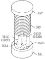
- FIG. 2A is an exploded perspective view of the magnetic pole coil module.
- Figure 2b is a perspective view of the coupling of the magnetic pole coil module.
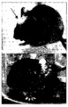
- Figure 3 (a) shows an example in which the lower connecting plate is fixed to the skull of the animal.
- FIG 3 (b) shows an example in which the stimulation coil module wound around the stimulation coil is fixed to the skull of the animal.
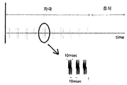
- FIG. 4 is a waveform diagram of a control signal used in the magnetic stimulation device.
- 5 is a result graph of the magnetic stimulation experiments found through the pressure stimulation experiments.
- the magnetic stimulation device 100 is a DC power supply unit 110, an inverter 120, a capacitor 130, a variable capacitor 140, the current probe 150, the magnetic pole coil module 160, and the controller 170.
- the DC power supply unit 110 generates a DC current required to generate a magnetic field for magnetic stimulation in the magnetic stimulation device 100.
- the inverter 120 converts the DC current output from the DC power supply unit 110 into an AC current.
- the inverter 120 may include an inverter of any type for converting a DC current into an alternating current, including an H bridge type inverter and a half bridge type inverter.
- the capacitor 130 cancels the inductance component of the magnetic pole coil of the magnetic pole coil module 150 according to the frequency of the alternating current supplied from the inverter 120. Accordingly, the capacitance of the capacitor 130 is set to a value suitable for canceling the inductance component.
- variable capacitor 140 finely adjusts the resonance frequency determined by the stimulation coil and the capacitor 130 to match an effective frequency for brain stimulation.
- the variable capacitor 140 may be replaced with a variable inductor as needed.
- coordinating the resonant frequency to match the effective frequency for brain stimulation is a brain found by observing the behavioral change of the animal under test while adjusting the resonant frequency in a predetermined unit (for example, 1 KHz) as shown in FIG. It means to match the frequency that is effective for the stimulus.
- a predetermined unit for example, 1 KHz
- the current probe 150 measures an AC current amount and a frequency output from the variable capacitor 140 and outputs a detection signal DET according thereto.
- the stimulation coil module 160 has a stimulation coil and is fixedly installed at a position capable of stimulating any cerebral zone of the animal.
- the magnetic pole coil conducts a current supplied through the variable capacitor 130. Accordingly, an alternating magnetic field is generated in the stimulation coil.
- the alternating magnetic field is generated through the skull of an animal (eg, a mouse) to generate an induced current in nerve cells of the cortex.
- the induced current stimulates nerve cells, thereby inducing an excitatory or inhibitory effect of the nerve cells to achieve a predetermined stimulation purpose.
- the stimulation coil module 150 as described above is light enough to be applied to an animal such as an experimental mouse in consideration of stimulating the cranial nerve of an animal such as an experimental mouse, and the size is large enough not to disturb the movement of the animal. It is small and has a structure capable of outputting a large magnetic field as required.
- the magnetic pole coil provided in the magnetic pole coil module 150 has a structure that generates a minimum heat according to the flow of the alternating current.
- the controller 170 outputs a control signal CTL for controlling the driving of the inverter 120.
- the control signal CTL may have various carrier frequencies according to a protocol of a stimulus signal (magnetic field) applied to an animal's brain. As such, when the control signal CTL has a carrier frequency, a repetition frequency and a pulse width through pulse modulation may be used in various combinations.
- Figure 2a is an exploded perspective view of the magnetic pole coil module 160 having the above characteristics
- Figure 2b is a coupling perspective view of the magnetic pole coil module 160, as shown therein, the lower connecting plate 161, the magnetic pole coil support ( 162 and stimulation coil 163.
- the lower connection plate 161 serves to fix the magnetic pole coil module 160 to the skull of the animal.
- the lower connecting plate 161 has a plurality of holes 161A, 161B formed to penetrate in the vertical direction.
- the bottom surface of the lower connecting plate 161 is bonded to the skull of the animal by concrete or other adhesive member.
- a plurality of support rods 161C, 161D are formed in the vertical direction.
- support rod fixtures 162C and 162D are formed at positions opposite to the support rods 161C and 161D.
- the lower connecting plate 161 has an example of a disc shape, but the shape thereof is not limited to the disc shape, but may be implemented in various shapes.
- the magnetic pole coil 163 is wound around the magnetic pole coil support 162 fixed as described above.
- the magnetic pole support 162 is preferably made of a material having no magnetic permeability that does not exhibit interference of the magnetic field.
- the lower connecting plate 161 and the pole coil support 162 may be made of a light weight material (eg, plastic) so as not to disturb the movement of the animal.
- the lower connecting plate 161 and the magnetic pole coil support 162 may be made of a material having a permeability close to 1 in order not to affect the magnetic field. Examples of the material having a magnetic permeability close to 1 include paramagnetic bodies containing any one of aluminum, tin, platinum, and iridium or diamagnetic bodies containing any one of hydrogen, water, quartz, lead, copper, and zinc.
- Figure 3 (a) shows an example in which the lower connecting plate 161 is fixed to the skull of the animal
- Figure 3 (b) is a magnetic pole coil module 160 including the magnetic pole coil 163 is the animal It shows an example fixed to the skull.
- Figure 4 shows an example of the control signal used in the magnetic stimulation device 100, a high frequency that varies from 85 kHz to 91 kHz, and applied an arbitrary protocol for smooth stimulation.
- the magnetic pole coil support 162 wound around the magnetic pole coil support 162 is fixed to the skull of the animal as described above, and allows the animal to adapt to the weight of the magnetic pole for a certain time. The intensity of the pressure with which the animal responds is then recorded according to the pressure stimulated.
- the magnetic stimulation apparatus 100 can be miniaturized and can be manufactured at low cost because it can be implemented with relatively simple circuits.
- FIG. 5 shows that there is no effect on brain stimulation from 85KHz to 88KHz when the resonance frequency is adjusted in units of 1KHz, but the behavioral change of the observed animal appears even at a small stimulus intensity at 85KHz to 91KHz, indicating the effect of brain stimulation.
- Experimental results since the effective frequency for brain stimulation is different for each animal, it is necessary to observe the behavior change of the animal under test while adjusting the frequency as described above.
Landscapes
- Health & Medical Sciences (AREA)
- Life Sciences & Earth Sciences (AREA)
- Public Health (AREA)
- Veterinary Medicine (AREA)
- Radiology & Medical Imaging (AREA)
- Biomedical Technology (AREA)
- Animal Behavior & Ethology (AREA)
- General Health & Medical Sciences (AREA)
- Engineering & Computer Science (AREA)
- Nuclear Medicine, Radiotherapy & Molecular Imaging (AREA)
- Physics & Mathematics (AREA)
- Biophysics (AREA)
- Pathology (AREA)
- Heart & Thoracic Surgery (AREA)
- Medical Informatics (AREA)
- Molecular Biology (AREA)
- Surgery (AREA)
- Magnetic Treatment Devices (AREA)
Abstract
본 발명은 수술이나 마취 없이 뇌신경을 자극하여 실험용쥐와 같은 동물의 뇌질환을 치료하는 자기자극 장치를 구현함에 있어서, 충분히 가볍고 동물의 움직임에 별다른 제약을 주지 않는 구조를 갖도록 하는 기술에 관한 것이다. 이러한 본 발명은 자극코일을 구비하여 동물의 대뇌구역에 자극을 줄 수 있는 위치에 고정 설치되고, 가변 커패시터를 통해 공급되는 전류를 상기 자극코일에 도통시켜 교류자기장을 발생하는 자극코일 모듈(160)을 구비하되, 상기 자극코일 모듈(160)은 하부연결판(161), 자극코일 지지대(162) 및 자극코일(163)을 구비하는 것을 특징으로 한다.
Description
본 발명은 수술이나 마취 없이 뇌신경을 자극하여 실험용쥐와 같은 동물의 뇌질환을 치료하는 기술에 관한 것으로, 특히 동물의 뇌신경을 자극하기 위한 자기자극 장치를 구현함에 있어서 충분히 가볍고 동물의 움직임에 별다른 제약을 주지 않는 자극부를 구비하고 주파수 조절이 가능한 교류전류를 발생시킬 수 있도록 한 경두개 자기자극 장치에 관한 것이다.
근래 들어, 뇌 신경자극을 위한 다양한 기술들에 대한 연구개발이 활발하게 이루어지고 있다. 뇌를 자극시켜서 소정의 목적을 달성하는 두뇌 자극술(brain stimulation)은 크게 침습식(invasive)과 비침습식(non-invasive)으로 구분된다.
침습식 두뇌자극술은 수술을 통하여 전극을 뇌에 침투시키고, 전극에 전기 신호를 인가하는 방법이며, 비침습식 두뇌자극술은 두개골 외부의 전극에 전기 신호를 인가하여 뇌 신경을 자극하는 방법이다.
대표적인 침습식 두뇌 자극술은 심부뇌자극(deep brain stimulation)이며, 비침습식 자두뇌 자극술은 경두개 자기 자극(TMS: transcranial magnetic stimulation), 경두개 직류자극(tDCS: transcranial direct current stimulation) 및 경두개 랜덤 노이즈 자극(tRNS: transcranial random noise stimulation)이다.
경두개 직류자극법(tDCS)은 연속적으로 수행되며 수 mA 정도의 약한 직류전류가 두 개 또는 그 이상의 전극에서 두피를 통해 흐르도록 하고 있다. 이때 흐르는 직류전류는 피질의 신경세포들의 막 전위의 작은 변경 및 발화율의 변화를 초래하며, 그에 따라 이의 흥분 레벨이 영향을 받는다.
경두개 자기 자극법(TMS)은 머리의 표면의 위에 있는 자기 코일에 1 밀리세컨드(ms)보다 짧은 시간 동안 전류가 흐르게 하고, 이때 자기 코일에서 발생하는 자기장을 이용하여 뇌를 자극한다. 자기장은 두개골을 통과하여 피질의 신경세포에서 유도전류를 발생시킨다. 따라서, 교류전류는 코일을 통해서 자기 에너지로 변환된 후 신경 세포들에서 전류로 전환된다. 유도전류가 운동피질을 자극할 때 운동신경에 대해 흥분 또는 억제 효과를 나타내는 것으로 알려져 있다. 경두개 자기 자극술과 관련하여 우울증 치료에 대한 효과, 신경병성 통증에 대한 임상 효과 및 파킨스씨병에 대한 임상 효과와 같은 것이 다수 보고되고 있다.
최근에 발표된 반복적 경두개 자기 자극(repetitive transcranial magnetic stimulation: rTMS)을 통한 뇌 자기 자극 연구에 의하면 우울증, 파킨슨씨병, 뇌졸중 후 기능 손상, 간질, 만성 신경병증성 통증 등의 치료에 효과가 있는 것으로 보고되고 있다. 반복적인 경두개 자기 자극이 대뇌 피질에 영향을 주는 것으로 알려졌지만 치료 기전이 정확하게 밝혀진 것은 아니다. 따라서, 실험용쥐와 같은 동물 모델을 이용한 경두개 자기 자극 실험을 통해 대뇌 피질에 주는 영향 및 치료 기전을 알아내기 위한 연구 개발이 활발하게 진행되고 있다.
그러나, 종래 기술에 의한 경두개 자기자극 장치는 자극 코일의 크기가 매우 커서 실험용쥐와 같은 동물에 적용하는데 어려움이 있다.
또한, 종래 기술에 의한 경두개 자기자극 장치는 전력 소모량이 많은 문제점이 있고, 가청주파수 대역에서 충전/방전을 이용한 전류흐름을 사용하여 소음이 심하게 발생되고 이에 의해 치료에 방해가 되는 문제점이 있다.
본 발명이 해결하고자 하는 과제는 실험용쥐와 같은 동물의 경두개 자기 자극을 주기 위한 자기 자극 장치를 구현함에 있어서 가볍고 동물의 움직임에 별다른 제약을 주지 않는 자극 코일을 포함하는 자극코일 모듈을 구비하는데 있다.
또한, 본 발명이 해결하고자 하는 다른 과제는 가변 커패시터 또는 가변 인덕터를 이용하여 자극 신호의 주파수 변화에 따른 자극 효과를 알아볼 수 있도록 하는데 있다.
또한, 본 발명이 해결하고자 하는 다른 과제는 펄스변조기법을 사용하여 다양한 프로토콜의 신호를 자극 신호로 사용할 수 있도록 하는데 있다.
상기 기술적 과제를 이루기 위한 본 발명의 실시예에 따른 경두개 자기자극 장치는, 직류전원부에서 출력되는 직류전류를 교류전류로 변환하여 출력하는 인버터; 상기 인버터로부터 공급되는 교류전류의 주파수에 따라 자극코일에서 나타나는 인덕턴스 성분을 상쇄하는 커패시터; 상기 자극코일과 상기 커패시터에 의해 결정되는 공진 주파수를 조정하면서 실험 대상 동물의 행동 변화를 관찰하여 찾아낸 뇌자극에 효과가 있는 주파수와 일치시키기 위한 가변 커패시터; 및 상기 자극코일을 구비하여 동물의 대뇌구역에 자극을 줄 수 있는 위치에 고정 설치되고, 상기 가변 커패시터를 통해 공급되는 전류를 상기 자극코일에 도통시켜 교류자기장을 발생하는 자극코일 모듈을 포함하는 것을 특징으로 한다.
본 발명은 경두개 자기 자극 장치를 구현함에 있어서, 구성요소인 자기 코일 및 지지대의 무게를 가볍게 함으로써, 실험용쥐와 같은 동물이 짧은 시간에 적응 할 수 있는 효과가 있다.
또한, 인버터 회로를 사용하여 충전/방전시 발생하는 소음을 제거함으로써, 제품에 대한 신뢰성이 향상되는 효과가 있다.
또한, 본 발명은 자기 자극신호의 주파수에 따른 압력 자극 반응의 역치값이 다르게 나타나는 것을 바탕으로 뇌 신경회로를 분석하는 수단으로 활용할 수 있는 이점이 있다.
또한, 본 발명의 자기 자극 장치를 이용하는 경우, 비교적 간단한 회로들로 구현할 수 있으며, 주파수 조절을 통해 경두개 자기 자극에 필요한 신호의 전력을 최소화할 수 있는 효과가 있다. 이에 따라, 기존의 경두개 자기 자극 장치의 소형화 및 저가 제작이 가능하므로, 휴대용 경두개 자기 자극 장비 등의 응용분야에 널리 적용할 수 있는 효과가 있다.
도 1은 본 발명의 실시예에 따른 경두개 자기자극 장치의 블록도이다.
도 2a는 자극코일 모듈의 분해 사시도이다.
도 2b는 자극코일 모듈의 결합 사시도이다.
도 3의 (a)는 하부연결판이 동물의 두개골에 고정 설치된 예를 나타낸 것이다.
도 3의 (b)는 자극 코일이 권취된 자극코일 모듈이 동물의 두개골에 고정 설치된 예를 나타낸 것이다.
도 4는 자기 자극 장치에 사용되는 제어신호의 파형도이다.
도 5는 압력 자극 실험을 통해 알아본 자기 자극 실험의 결과 그래프이다.
이하, 첨부한 도면을 참조하여 본 발명의 바람직한 실시예를 상세히 설명하면 다음과 같다.
도 1은 본 발명의 실시예에 따른 경두개 자기자극 장치의 블록도로서 이에 도시한 바와 같이, 자기 자극 장치(100)는 직류전원부(110), 인버터(120), 커패시터(130), 가변 커패시터(140), 전류프로브(150), 자극코일 모듈(160) 및 제어부(170)를 포함한다.
직류전원부(110)는 자기 자극 장치(100)에서 자기 자극을 위한 자기장을 발생하는데 필요로 하는 직류전류를 생성한다.
인버터(120)는 상기 직류전원부(110)에서 출력되는 직류전류를 교류전류로 변환해준다. 상기 인버터(120)는 H 브릿지 방식의 인버터 및 하프 브릿지 방식의 인버터를 포함하여 직류전류를 교류전류로 변환해주는 모든 방식의 인버터를 포함할 수 있다.
커패시터(130)는 상기 인버터(120)로부터 공급되는 교류전류의 주파수에 따라 자극코일 모듈(150)의 자극코일에서 나타나는 인덕턴스 성분을 상쇄하는 역할을 한다. 이에 따라, 상기 커패시터(130)의 용량은 상기 인덕턴스 성분을 상쇄하는데 적당한 값으로 설정된다.
가변 커패시터(140)는 상기 자극코일과 상기 커패시터(130)에 의해 결정되는 공진 주파수를 미세 조정하여 뇌자극에 효과적인 주파수와 일치시키는 역할을 한다. 상기 가변 커패시터(140)는 필요에 따라 가변 인덕터로 대체될 수 있다.
여기서, "상기 공진 주파수를 미세 조정하여 뇌자극에 효과적인 주파수와 일치시키는" 것은 상기 공진 주파수를 도 5에서와 같이 소정 단위(예: 1KHz)로 조정하면서 실험 대상 동물의 행동 변화를 관찰하여 찾아낸 뇌자극에 효과가 있는 주파수와 일치시키는 것을 의미한다.
전류 프로브(150)는 상기 가변 커패시터(140)에서 출력되는 교류 전류량과 주파수를 측정하여 그에 따른 검출신호(DET)를 출력한다.
자극코일 모듈(160)은 자극코일을 구비하여 동물의 임의의 대뇌구역에 자극을 줄 수 있는 위치에 고정 설치된다. 상기 자극코일은 상기 가변 커패시터(130)를 통해 공급되는 전류를 도통시킨다. 이에 따라, 상기 자극코일에 교류자기장이 발생되는데, 이렇게 발생되는 교류자기장은 동물(예: 실험용쥐)의 두개골을 통과하여 피질의 신경세포에 유도전류를 발생시킨다. 상기 유도전류가 신경세포를 자극하게 되고, 이에 의해 신경세포의 흥분 또는 억제 효과가 유발되어 소정의 자극 목적을 달성할 수 있게 된다.
그런데, 상기와 같은 자극코일 모듈(150)은 실험용쥐와 같은 동물의 뇌신경을 자극하기 위한 것을 감안하여 실험용쥐와 같은 동물에 적용하는데 적당하도록 무게가 가볍고, 동물의 움직임을 방해하지 않을 정도로 사이즈가 작으며, 필요로 하는 정도의 큰 자기장을 출력할 수 있는 구조를 갖는다. 그리고, 상기 자극코일 모듈(150)에 구비된 자극코일은 교류전류의 흐름에 따라 최소한으로 발열되는 구조를 갖는다.
제어부(170)는 상기 인버터(120)의 구동을 제어하기 위한 제어신호(CTL)를 출력한다. 상기 제어신호(CTL)는 동물의 대뇌에 가해지는 자극신호(자기장)의 프로토콜에 따라서 다양한 반송 주파수를 가질 수 있다. 이와 같이 제어신호(CTL)가 반송 주파수를 가질 경우 펄스 변조를 통한 반복 주파수와 펄스폭은 다양한 조합으로 사용될 수 있다.
도 2a는 상기와 같은 특징을 갖는 자극코일 모듈(160)의 분해 사시도이고, 도 2b는 자극코일 모듈(160)의 결합 사시도로서 이에 도시한 바와 같이, 하부연결판(161), 자극코일 지지대(162) 및 자극코일(163)을 포함한다.
하부연결판(161)은 자극코일 모듈(160)을 동물의 두개골에 고정시키는 역할을 한다. 이를 위해 상기 하부연결판(161)에는 수직방향으로 관통되게 형성된 복수개의 구멍(161A),(161B)이 형성되어 있다. 하부연결판(161)의 바닥면은 콘크리트나 기타 접착부재에 의해 동물의 두개골에 접착된다. 하부연결판(161)의 상부면에는 수직 방향으로 복수 개의 지지봉(161C),(161D)이 형성되어 있다.
자극코일 지지대(162)의 하부에는 상기 지지봉(161C),(161D)의 대향하는 위치에 지지봉 고정구(162C),(162D)가 형성된다.
2 개의 나사(도면에 미표시)가 상기 나사 상기 구멍(161A),(161B)을 각기 관통하여 동물의 두개골에 각각 삽입 고정된다. 이에 따라, 상기 하부연결판(161)이 상기 콘트리트 및 나사에 의해 동물의 두개골에 단단하게 고정된다. 이와 같은 상태에서, 상기 자극코일 지지대(162)의 지지봉 고정구(162C),(162D)가 상기 지지봉(161C),(161D)에 체결되므로 상기 자극코일 지지대(162)를 보다 편리하게 상기 두개골에 고정시킬 수 있게 된다.
여기서, 하부연결판(161)이 원반 형상인 것을 예로 하였으나 이의 형상이 원반 형상으로 한정되는 것이 아니라 다양한 형상으로 구현될 수 있다.
상기와 같이 고정된 자극코일 지지대(162)에는 상기 자극코일(163)이 권취된다. 상기 자극코일 지지대(162)는 자기장의 간섭을 보이지 않는 투자율이 없는 물질로 제작되는 것이 바람직하다. 상기 하부 연결판(161) 및 자극코일 지지대(162)는 무게가 가벼운 물질(예: 플라스틱)로 제작되어 동물의 움직임을 방해하지 않는 것이 바람직하다. 그리고, 상기 하부 연결판(161) 및 자극코일 지지대(162)는 자기장에 영향을 미치지 않게 하기 위해 투자율이 1에 가까운 재질로 제작되는 것이 바람직하다. 상기 투자율이 1에 가까운 재질의 예로써, 알루미늄, 주석, 백금 및 이리듐 중 어느 하나를 포함하는 상자성체 또는 수소, 물, 수정, 납, 구리 및 아연 중 어느 하나를 포함하는 반자성체를 들 수 있다.
도 3의 (a)는 상기 하부연결판(161)이 동물의 두개골에 고정 설치된 예를 나타낸 것이고, 도 3의 (b)는 자극 코일(163)을 포함하는 자극코일 모듈(160)이 동물의 두개골에 고정 설치된 예를 나타낸 것이다.
실험용쥐와 같은 동물은 끊임없이 움직이는 특징이 있으므로 동물의 행동변화를 관찰하고자 할 때 동물을 마취할 수 없다. 하지만, 상기와 같은 구조를 갖는 자극코일 모듈(160)을 구비한 자기 자극 장치(100)를 이용함으로써, 동물의 행동변화를 편리하고 정확하게 관찰할 수 있다.
도 4는 자기 자극 장치(100)에 사용되는 제어신호의 예를 나타낸 것으로, 85 kHz ~ 91 kHz까지 변화되는 고주파이며, 원활한 자극을 위해 임의의 프로토콜을 적용하였다.
동물을 대상으로 압력 자극에 반응하는 정도를 측정하여 경두개 자기 자극효과를 알 수 있다. 이를 위해 상기 자극 코일(163)이 권취된 자극코일 지지대(162)를 동물의 두개골에 상기와 같이 고정 설치하고, 동물로 하여금 일정 시간동안 자극부의 무게에 적응하도록 한다. 이후, 자극되는 압력에 따라 동물이 반응하는 압력의 세기를 기록한다.
도 5는 압력 자극 실험을 통해 알아본 자기 자극 실험의 결과이다. 동물의 우뇌 감각피질을 자극 했을 때 왼발의 압력 자극에 대한 역치 감소가 주파수에 따라 다르게 나타나는 것을 알 수 있다.
상기 가변 커패시터(140) 또는 가변 인덕터를 조절하여 자기 자극이 효과적으로 나타나는 주파수를 선택하여 자기 자극 시술을 수행할 경우 기존의 경두개 자극 장치에 비하여 적은 소모전력으로 자극 효과를 얻을 수 있다. 또한, 비교적 간단한 회로들로 구현할 수 있어 자기 자극 장치(100)를 소형화 할 수 있으며, 저가로 제작할 수 있다.
예를 들어, 도 5는 공진 주파수를 1KHz 단위로 조정할 때 85KHz부터 88KHz 까지는 뇌자극에 효과가 없으나 85KHz부터 91KHz에서는 작은 자극의 세기에서도 관찰 대상 동물의 행동 변화가 나타나서 뇌자극의 효과가 있는 것을 나타낸 실험결과이다. 그런데, 뇌자극에 효과적인 주파수는 동물에 따라 다르게 나타나므로 상기와 같이 주파수를 조정하면서 실험 대상 동물의 행동 변화를 관찰하는 것이 필요하다.
이상에서 본 발명의 바람직한 실시예에 대하여 상세히 설명하였지만, 본 발명의 권리범위가 이에 한정되는 것이 아니라 다음의 청구범위에서 정의하는 본 발명의 기본 개념을 바탕으로 보다 다양한 실시예로 구현될 수 있으며, 이러한 실시예들 또한 본 발명의 권리범위에 속하는 것이다.
Claims (10)
- 직류전원부에서 출력되는 직류전류를 교류전류로 변환하여 출력하는 인버터;상기 인버터로부터 공급되는 교류전류의 주파수에 따라 자극코일에서 나타나는 인덕턴스 성분을 상쇄하는 커패시터;상기 자극코일과 상기 커패시터에 의해 결정되는 공진 주파수를 조정하면서 실험 대상 동물의 행동 변화를 관찰하여 찾아낸 뇌자극에 효과가 있는 주파수와 일치시키기 위한 가변 커패시터; 및상기 자극코일을 구비하여 동물의 대뇌구역에 자극을 줄 수 있는 위치에 고정 설치되고, 상기 가변 커패시터를 통해 공급되는 전류를 상기 자극코일에 도통시켜 교류자기장을 발생하는 자극코일 모듈을 포함하는 것을 특징으로 하는 경두개 자기자극 장치.
- 제1항에 있어서, 상기 커패시터의 용량은상기 인덕턴스 성분을 상쇄할 수 있는 값으로 설정되는 것을 특징으로 하는 경두개 자기자극 장치.
- 제1항에 있어서, 상기 자극코일 모듈은상기 자극코일 모듈을 상기 동물의 두개골에 고정시키는 역할을 하는 하부연결판; 및상기 하부연결판과 체결되어 상기 자극코일이 권취되는 자극코일 지지대를 포함하는 것을 특징으로 하는 경두개 자기자극 장치.
- 제3항에 있어서, 상기 하부 연결판은접착부재에 의해 상기 동물의 두개골에 고정 설치되는 것을 특징으로 하는 경두개 자기자극 장치.
- 제4항에 있어서, 상기 접착부재는콘크리트를 포함하는 것을 특징으로 하는 경두개 자기자극 장치.
- 제3항에 있어서, 상기 하부 연결판은원반 형상의 구조를 갖는 것을 특징으로 하는 경두개 자기자극 장치.
- 제3항에 있어서, 상기 하부 연결판은수직방향으로 관통되게 형성된 복수개의 구멍; 및상기 하부연결판의 상부면에는 수직 방향으로 형성된 복수 개의 지지봉을 포함하는 것을 특징으로 하는 경두개 자기자극 장치.
- 제3항에 있어서, 상기 자극코일 지지대는상기 하부연결판에 형성된 복수 개의 지지봉과 체결되는 복수 개의 지지봉 고정구를 포함하는 것을 특징으로 하는 경두개 자기자극 장치.
- 제3항에 있어서, 상기 하부 연결판 및 상기 자극코일 지지대는상자성체 또는 반자성체의 재질로 제작된 것을 특징으로 하는 경두개 자기자극 장치.
- 제1항에 있어서, 상기 자기자극 장치는상기 인버터의 구동을 제어하기 위하여 상기 동물의 대뇌에 가해지는 자극신호의 프로토콜에 따라서 다양한 반송 주파수를 갖는 제어신호를 출력하는 제어부를 더 포함하는 것을 특징으로 하는 경두개 자기자극 장치.
Applications Claiming Priority (2)
| Application Number | Priority Date | Filing Date | Title |
|---|---|---|---|
| KR10-2016-0028284 | 2016-03-09 | ||
| KR1020160028284A KR101733589B1 (ko) | 2016-03-09 | 2016-03-09 | 경두개 자기자극 장치 |
Publications (1)
| Publication Number | Publication Date |
|---|---|
| WO2017155226A1 true WO2017155226A1 (ko) | 2017-09-14 |
Family
ID=59789665
Family Applications (1)
| Application Number | Title | Priority Date | Filing Date |
|---|---|---|---|
| PCT/KR2017/001857 Ceased WO2017155226A1 (ko) | 2016-03-09 | 2017-02-20 | 경두개 자기자극 장치 |
Country Status (2)
| Country | Link |
|---|---|
| KR (1) | KR101733589B1 (ko) |
| WO (1) | WO2017155226A1 (ko) |
Cited By (3)
| Publication number | Priority date | Publication date | Assignee | Title |
|---|---|---|---|---|
| CN113648541A (zh) * | 2021-08-13 | 2021-11-16 | 上海大学 | 一种磁刺激结合脑信号采集同步的一体装置 |
| WO2022214195A1 (en) * | 2021-04-09 | 2022-10-13 | Azyro Sa | Medical device, system and method for magnetic field treatment and/or diagnosis |
| CN116850464A (zh) * | 2023-08-22 | 2023-10-10 | 武汉依瑞德医疗设备新技术有限公司 | 一种家用经颅磁刺激设备 |
Families Citing this family (2)
| Publication number | Priority date | Publication date | Assignee | Title |
|---|---|---|---|---|
| KR102334132B1 (ko) * | 2019-11-20 | 2021-12-02 | 가톨릭관동대학교산학협력단 | 경두개 자기 자극 및 신경 신호 측정 장치 및 그 방법 |
| KR102833346B1 (ko) * | 2023-01-09 | 2025-07-11 | 부산대학교 산학협력단 | 진폭 변조 경두개 자기자극 방법 및 장치 |
Citations (4)
| Publication number | Priority date | Publication date | Assignee | Title |
|---|---|---|---|---|
| KR20080015923A (ko) * | 2005-06-15 | 2008-02-20 | 연팽 젱 | 중추 신경계를 위한 자기 자극 장치, 회로 및 그 이용, 그리고 그 장치의 이용 방법 |
| KR20090061460A (ko) * | 2007-12-11 | 2009-06-16 | 엘지전자 주식회사 | 인버터 리니어 압축기 제어 장치 및 방법 |
| KR20150002770A (ko) * | 2012-04-06 | 2015-01-07 | 뉴포트 브레인 리서치 래버러토리 인코포레이티드 | Rtms 장치 |
| US20150099963A1 (en) * | 2013-10-03 | 2015-04-09 | Medical University Of Vienna | METHOD AND SYSTEM FOR COMBINED TRANSCRANIAL MAGNETIC SIMULATION (TMS) AND FUNCTIONAL MAGNETIC RESONANCE IMAGING (fMRI) STUDIES |
-
2016
- 2016-03-09 KR KR1020160028284A patent/KR101733589B1/ko not_active Expired - Fee Related
-
2017
- 2017-02-20 WO PCT/KR2017/001857 patent/WO2017155226A1/ko not_active Ceased
Patent Citations (4)
| Publication number | Priority date | Publication date | Assignee | Title |
|---|---|---|---|---|
| KR20080015923A (ko) * | 2005-06-15 | 2008-02-20 | 연팽 젱 | 중추 신경계를 위한 자기 자극 장치, 회로 및 그 이용, 그리고 그 장치의 이용 방법 |
| KR20090061460A (ko) * | 2007-12-11 | 2009-06-16 | 엘지전자 주식회사 | 인버터 리니어 압축기 제어 장치 및 방법 |
| KR20150002770A (ko) * | 2012-04-06 | 2015-01-07 | 뉴포트 브레인 리서치 래버러토리 인코포레이티드 | Rtms 장치 |
| US20150099963A1 (en) * | 2013-10-03 | 2015-04-09 | Medical University Of Vienna | METHOD AND SYSTEM FOR COMBINED TRANSCRANIAL MAGNETIC SIMULATION (TMS) AND FUNCTIONAL MAGNETIC RESONANCE IMAGING (fMRI) STUDIES |
Cited By (3)
| Publication number | Priority date | Publication date | Assignee | Title |
|---|---|---|---|---|
| WO2022214195A1 (en) * | 2021-04-09 | 2022-10-13 | Azyro Sa | Medical device, system and method for magnetic field treatment and/or diagnosis |
| CN113648541A (zh) * | 2021-08-13 | 2021-11-16 | 上海大学 | 一种磁刺激结合脑信号采集同步的一体装置 |
| CN116850464A (zh) * | 2023-08-22 | 2023-10-10 | 武汉依瑞德医疗设备新技术有限公司 | 一种家用经颅磁刺激设备 |
Also Published As
| Publication number | Publication date |
|---|---|
| KR101733589B1 (ko) | 2017-05-08 |
Similar Documents
| Publication | Publication Date | Title |
|---|---|---|
| WO2017155226A1 (ko) | 경두개 자기자극 장치 | |
| US11253730B2 (en) | Ultrasound deep brain stimulation method and system | |
| Anastassiou et al. | Ephaptic coupling to endogenous electric field activity: why bother? | |
| Rahman et al. | Cellular effects of acute direct current stimulation: somatic and synaptic terminal effects | |
| KR100866378B1 (ko) | 뇌파를 주요치료정보로 사용하는 저주파 자기물리치료장치 | |
| Moreno-Duarte et al. | Transcranial electrical stimulation: Transcranial direct current stimulation (tDCS), transcranial alternating current stimulation (tACS), transcranial pulsed current stimulation (tPCS), and transcranial random noise stimulation (tRNS) | |
| US9999780B2 (en) | Magnetic stimulation having a freely selectable pulse shape | |
| Rahman et al. | Multilevel computational models for predicting the cellular effects of noninvasive brain stimulation | |
| Reato et al. | Principles of transcranial direct current stimulation (tDCS): introduction to the biophysics of tDCS | |
| US20250108228A1 (en) | Miniaturized c-shaped coil and system for transcranial magnetic stimulation | |
| WO2015076444A1 (ko) | 뇌파 측정 및 두뇌 자극 시스템 | |
| Rotem et al. | Magnetic stimulation of curved nerves | |
| CN113952621A (zh) | 一种非侵入式复合刺激系统及方法 | |
| Vander Vorst et al. | 1990-1995 Advances in investigating the interaction of microwave fields with the nervous system | |
| Ye et al. | Cellular mechanisms underlying carry-over effects after magnetic stimulation | |
| Miranda et al. | Computational models of non-invasive brain and spinal cord stimulation | |
| Wang et al. | Physics and biophysics fundamentals of transcranial stimulation | |
| WO2026005198A1 (ko) | 전기장과 자기장을 동시에 이용하는 뇌자극 장치 | |
| WO2015148392A2 (en) | System for diagnosing and treatment of pancreas, other tissues and organs and other medical conditions | |
| Leo et al. | Computer modelling of brain cortex excitation by magnetic field pulses | |
| Jamali et al. | A new method of brain stimulation at ultra-high frequency | |
| Jiang et al. | Low intensity repetitive transcranial magnetic stimulation modulates spontaneous spiking activities in rat cortex | |
| Cattaneo | Transcranial magnetic stimulation | |
| Kagan et al. | Magnetic stimulation of mammalian peripheral nerves in vivo: an alternative to functional electrical stimulation | |
| Silny | Influence of low-frequency magnetic field (LMF) on the organism |
Legal Events
| Date | Code | Title | Description |
|---|---|---|---|
| NENP | Non-entry into the national phase |
Ref country code: DE |
|
| 121 | Ep: the epo has been informed by wipo that ep was designated in this application |
Ref document number: 17763489 Country of ref document: EP Kind code of ref document: A1 |
|
| 122 | Ep: pct application non-entry in european phase |
Ref document number: 17763489 Country of ref document: EP Kind code of ref document: A1 |