WO2017154431A1 - エネルギー送信装置、エネルギー受信装置、エネルギー送受信装置及びこれらを有するワイヤレス給電システム - Google Patents
エネルギー送信装置、エネルギー受信装置、エネルギー送受信装置及びこれらを有するワイヤレス給電システム Download PDFInfo
- Publication number
- WO2017154431A1 WO2017154431A1 PCT/JP2017/003841 JP2017003841W WO2017154431A1 WO 2017154431 A1 WO2017154431 A1 WO 2017154431A1 JP 2017003841 W JP2017003841 W JP 2017003841W WO 2017154431 A1 WO2017154431 A1 WO 2017154431A1
- Authority
- WO
- WIPO (PCT)
- Prior art keywords
- laser
- energy
- laser beams
- photoelectric conversion
- receiving
- Prior art date
- Legal status (The legal status is an assumption and is not a legal conclusion. Google has not performed a legal analysis and makes no representation as to the accuracy of the status listed.)
- Ceased
Links
Images




Classifications
-
- H—ELECTRICITY
- H02—GENERATION; CONVERSION OR DISTRIBUTION OF ELECTRIC POWER
- H02J—ELECTRIC POWER NETWORKS; CIRCUIT ARRANGEMENTS OR SYSTEMS FOR SUPPLYING OR DISTRIBUTING ELECTRIC POWER; SYSTEMS FOR STORING ELECTRIC ENERGY
- H02J50/00—Circuit arrangements or systems for wireless supply or distribution of electric power
- H02J50/30—Circuit arrangements or systems for wireless supply or distribution of electric power using light, e.g. lasers
-
- H—ELECTRICITY
- H02—GENERATION; CONVERSION OR DISTRIBUTION OF ELECTRIC POWER
- H02J—ELECTRIC POWER NETWORKS; CIRCUIT ARRANGEMENTS OR SYSTEMS FOR SUPPLYING OR DISTRIBUTING ELECTRIC POWER; SYSTEMS FOR STORING ELECTRIC ENERGY
- H02J50/00—Circuit arrangements or systems for wireless supply or distribution of electric power
- H02J50/40—Circuit arrangements or systems for wireless supply or distribution of electric power using two or more transmitting or receiving devices
Definitions
- the technology disclosed herein relates to an energy transmitter, an energy receiver, an energy transceiver, and a wireless power supply system including these.
- Japanese Patent Laid-Open No. 2010-166675 discloses a system for feeding laser light to a movable body provided with receiving means for converting laser light into electric power by supplying means for converting a power source into laser light. .
- This specification discloses an energy transmitter and an energy receiver.
- the energy transmitter and the energy receiver disclosed herein may be used alone or both may be used simultaneously as an energy transceiver.
- the energy transmission device is configured to control the irradiation direction of the plurality of laser beams and to cause the optical axes of the plurality of laser beams to intersect at one point with the laser irradiation device configured to emit the plurality of laser beams. And an irradiation direction control device.
- the above-described energy transmission device causes a plurality of laser beams to intersect at one point by the irradiation direction control device.
- the plurality of laser beams are collected at one point, all the energy of the plurality of laser beams is concentrated at that point. Therefore, by receiving the laser light at this point, large energy can be transmitted.
- the laser beam can be divided and emitted into a plurality of portions, energy of each laser beam can be reduced. For this reason, safety for the eyes can be secured.
- the energy receiving device is configured to measure the light intensities of the plurality of laser beams incident on the receiving surface, and a photoelectric conversion device configured to convert the plurality of laser beams incident on the receiving surface into electrical energy. To adjust the relative positional relationship between the optical axes of the plurality of laser beams and the receiving surface of the photoelectric conversion device so that the light intensities of the plurality of laser beams incident on the receiving surface increase. And a position adjusting device configured to
- the light intensity measuring device measures the light intensity of the laser beam incident on the receiving surface.
- the position adjusting device adjusts the relative position between the optical axis of the laser beam and the receiving surface so that the light intensity is increased based on the measurement result. Therefore, laser light can be received at a position where the light intensity of the laser light is high. Therefore, energy can be efficiently received.
- the present specification discloses a wireless power supply system having the above-described energy transmitter and / or energy receiver.
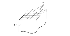
- FIG. 1 is an enlarged view of the receiving surface of the energy receiving apparatus of the first embodiment.
- FIG. 8 schematically shows a configuration of a wireless power supply system according to a second embodiment.
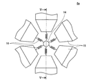
- FIG. 13 is a plan view schematically showing the configuration of an irradiation direction control device of the energy transmission device of the third embodiment.
- FIG. 5 is a cross-sectional view taken along the line VV of FIG. 4;
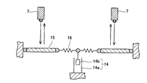
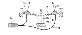
- FIG. 7 is a diagram showing the operation of the energy transmission device of the third embodiment.
- An energy transmission device disclosed in the present specification includes a laser irradiation device configured to irradiate a plurality of laser beams, and an irradiation direction control device configured to control an irradiation direction of the plurality of laser beams.
- the irradiation direction control device may be configured to intersect the optical axes of the plurality of laser beams at one point.
- the irradiation direction control device may be configured to be movable at a position where the optical axes of the plurality of laser beams intersect. According to such a configuration, it is possible to adjust the distance at which the plurality of laser beams are collected.
- the irradiation direction control device may be configured to be able to move the position where the optical axes of the plurality of laser beams intersect, based on the position of the receiving device that receives energy from the plurality of laser beams.
- the receiving device can be preferably irradiated with the laser light.
- the wavelength of each of the plurality of laser beams may be in the range of 1200 nm to 1400 nm. Such a configuration can reduce the risk to the eye.
- the laser irradiation apparatus has a plurality of laser light sources, and the laser light emitted from each of the plurality of laser light sources may correspond to each of the plurality of laser lights, or irradiation from one laser light source
- the laser beam may be branched to be irradiated with a plurality of laser beams.
- the energy receiving device disclosed in the present specification measures a photoelectric conversion device configured to convert laser light incident on the receiving surface into electrical energy, and measures the light intensity of the laser light incident on the receiving surface.
- the configuration is such that the relative positional relationship between the optical axis of the laser beam and the receiving surface of the photoelectric conversion device is adjusted so that the light intensity of the configured light intensity measuring device and the laser beam incident on the receiving surface increases.
- the position adjusting device may be provided.
- the light intensity measuring device may be configured to measure the distribution of light intensity in the receiving surface of the laser beam incident on the receiving surface of the photoelectric conversion device.
- the position adjusting device may be configured to adjust the relative positional relationship between the optical axis of the laser beam and the receiving surface of the photoelectric conversion device based on the distribution of the light intensity of the laser beam.
- the position adjusting device specifies the peak position of the light intensity of the laser light based on the distribution of the light intensity of the laser light, and the optical axis of the laser light and the photoelectric conversion device are set so that the center position of the receiving surface approaches the peak position. You may be comprised so that the relative positional relationship of a receiving surface may be adjusted. According to such a configuration, the energy of the laser light can be efficiently received.
- the photoelectric conversion device may have a photodiode array configured of a plurality of photodiodes.
- the conversion efficiency of the received laser light into energy can be improved.
- it may further include a position specifying device configured to specify the current position of the receiving surface of the photoelectric conversion device.
- the position adjusting device may be configured to adjust the relative positional relationship between the optical axis of the laser beam and the receiving surface of the photoelectric conversion device based on the current position of the receiving surface of the photoelectric conversion device. According to such a configuration, laser light can be stably received.
- the laser irradiation device of the energy transmitting device may be configured to modulate a plurality of laser beams corresponding to transmission data.
- the photoelectric conversion device of the energy receiving device may be configured to demodulate transmission data from the received laser light. According to such a configuration, data communication can be enabled.
- the wireless power supply system 1A of the first embodiment will be described with reference to the drawings.
- the wireless power supply system 1A includes an energy transmitting device 2 (hereinafter referred to as a transmitting device 2) and an energy receiving device 3 (hereinafter referred to as a receiving device 3).
- the transmission device 2 includes a laser irradiation device 4 and an irradiation direction control device 6.
- the laser irradiation device 4 has a plurality of laser light sources 7 and is configured to emit a plurality of laser beams parallel to each other.
- the wavelength of the laser light emitted from each of the plurality of laser light sources 7 is, for example, in the range of 1200 nm to 1400 nm. Further, the intensity of the laser light emitted from each of the plurality of laser light sources 7 is set to 16 mW or less.
- the irradiation direction control device 6 controls the irradiation direction of the laser light emitted from each of the plurality of laser light sources 7.
- a variable focus lens is used for the irradiation direction control device 6.
- the variable focus lens of the irradiation direction control device 6 is disposed at a position where the laser light emitted from each of the plurality of laser light sources 7 is transmitted. Laser light emitted from each of the plurality of laser light sources 7 enters the variable focus lens of the irradiation direction control device 6.
- the variable focus lens of the irradiation direction control device 6 is configured to condense each of the laser beams to be irradiated and to cross their optical axes at one point on the reception surface 8 of the reception device 3 described later. That is, the variable focus lens is configured such that the focal point of each incident laser beam coincides with the receiving surface 8 of the receiving device 3.
- the variable focus lens is configured to move the position of the focus by changing the position of the lens.
- the configuration of the variable focus lens may be such that the surface shape of the lens formed at the liquid-liquid interface is variable using an actuator.
- the receiving device 3 is a mobile body, and receives the laser light emitted from the transmitting device 2.
- the receiving device 3 includes a photoelectric conversion device 9, a light intensity measuring device 10, a position specifying device 11, and a position adjusting device 12.
- the photoelectric conversion device 9 converts laser light incident on the receiving surface 8 into electrical energy.
- a two-dimensional photodiode array in which a plurality of photodiodes are arranged on a plane is used as the photoelectric conversion device 9.
- Each of the plurality of photodiodes can cause a current to flow by the incident laser light (photon) exciting an electron and the generated carrier moving.
- the photoelectric conversion device 9 is not limited to the above, and may be, for example, a solar cell or a phototransistor.
- the light intensity measuring device 10 measures the light intensity of the laser beam incident on the receiving surface 8 for each photodiode. Specifically, the light intensity measuring device 10 acquires the distribution of light intensity measured for each photodiode as array data, and specifies the peak position of the light intensity of the laser light based on the array data.
- the position specifying device 11 specifies the current position of the receiving surface 8 of the photoelectric conversion device 9.
- An imaging camera is used for the position specifying device 11, and the current position of the receiving surface 8 is specified by recognizing the photoelectric conversion device 9 from the outside.
- the position specifying device 11 specifies the current center position of the receiving surface 8 from the current position of the receiving surface 8.
- the position specifying device 11 is not limited to the above.
- a GPS Global Positioning System
- the position specifying device 11 can specify the position of the receiving surface 8 based on the movement of the photoelectric conversion device 9 by the position adjusting device 12.
- the position adjusting device 12 adjusts the relative positional relationship between the optical axis of the laser beam and the receiving surface 8 of the photoelectric conversion device 9 so that the light intensity of the laser beam incident on the receiving surface 8 is increased.
- the position adjustment device 12 is configured to be communicable with the light intensity measurement device 10, and acquires data regarding the peak position of the light intensity of the laser light specified by the light intensity measurement device 10.
- the position adjustment device 12 is configured to be communicable with the position specifying device 11, and acquires data regarding the current center position of the receiving surface 8 of the photoelectric conversion device 9 specified by the position specifying device 11.
- the position adjusting device 12 approaches the peak position of the light intensity on the basis of the data on the peak position of the light intensity of the laser light and the data on the current center position of the receiving surface 8 of the photoelectric conversion device 9 Thus, the relative positional relationship between the optical axis of the laser beam and the receiving surface 8 of the photoelectric conversion device 9 is adjusted.
- the position adjustment device 12 has a wing for flying the photoelectric conversion device 9.
- the position adjustment device 12 may have a propeller, a tire traveling on the ground, a leg, and the like.
- the wireless power supply system 1A can wirelessly supply energy from the transmitter 2 to the receiver 3 by converting the laser light emitted from the transmitter 2 into power by the receiver 3.
- the transmission device 2 transmits large energy by condensing laser beams emitted from the plurality of laser light sources 7 at one point. Therefore, the energy of the laser beam which each laser light source 7 irradiates can be made small. For this reason, safety for the eyes can be secured.
- the wavelength of the laser light is in the range of 1200 nm to 1400 nm, which is an eye-safe band. The risk to the eye of laser light in this wavelength range is known to be mainly retinal damage by focusing on the retina.
- the laser beams emitted by the plurality of laser light sources 7 are imaged at different positions on the retina, the danger to the eye can be reduced.
- the above wavelength range has the largest energy (16 mW) of the laser beams classified into the safest class 1 in the safety standard, it is possible to transmit large energy to the receiver 3. it can.
- the receiving device 3 measures the light intensity of the laser light that the light intensity measuring device 10 makes incident on the receiving surface 8.
- the position adjusting device 12 adjusts the relative positional relationship between the optical axis of the laser beam and the receiving surface 8 so that the light intensity is increased based on the measurement result. Therefore, it is possible to position the center position of the receiving surface 8 at a position where the light intensity of the laser light is large and receive the laser light. Therefore, energy can be efficiently received.
- the band gap of the photodiode matches the wavelength of the laser beam to be emitted, the energy conversion efficiency can be increased.
- the laser irradiation device 4 of the transmission device 2 may be further configured to modulate a plurality of laser beams corresponding to desired transmission data. For example, by providing a light modulator in the laser irradiation device 4, it is possible to modulate the laser light in response to the transmission data and transmit the modulated laser light.
- the photoelectric conversion device 9 of the receiving device 3 may be configured to demodulate transmission data from the received laser light. For example, when the photoelectric conversion device 9 demodulates the laser light from the transmission device 2 into an electrical signal, transmission data of the laser light can be received.
- the transmission data may include a signal instructing movement of the reception device 3 which is a mobile.
- the position specifying device 11 transmits data on the current center position of the receiving surface 8 of the photoelectric conversion device 9 to the transmitting device 2, and the transmitting device 2 adjusts the data using laser light. It may be sent to the device 12. Further, the position specifying device 11 transmits data on the current center position of the receiving surface 8 of the photoelectric conversion device 9 to the transmitting device 2, and the irradiation direction control device 4 controls the optical axes of the plurality of laser beams based on the data. The position or direction of intersection at one point may be changed, or the transmitter 2 itself may be moved to intersect the optical axes of a plurality of laser beams at the reception surface 8 based on the data.
- the wireless power supply system 1B of the present embodiment is different from that of the first embodiment in the configuration of the laser irradiation device of the energy transmission device.
- the laser irradiation apparatus 4a has one laser light source 7a, a plurality of optical fibers 7b, and a plurality of collimate lenses 7c.
- the laser beam emitted from the laser light source 7a is branched into a plurality of laser beams by the plurality of optical fibers 7b.
- a collimating lens 7c is provided at the tip of each of the plurality of optical fibers, and a plurality of parallel laser beams are irradiated from the collimating lens 7c toward the variable focus lens of the irradiation direction control device 6.
- the intensity of each of the branched laser beams is 16 mW or less.
- the branched laser light is condensed on the receiving surface 8 of the photoelectric conversion device 9 of the receiving device 3 through the variable focus lens of the irradiation direction control device 6.
- the wireless power supply system 1B of the second embodiment since the laser light emitted from the laser light source 7a is branched, the same function and effect as the wireless power supply system 1A of the first embodiment can be obtained.
- the wireless power supply system of the third embodiment is different from that of Embodiment 1 in the configuration of the irradiation direction control device of the energy transmission device.
- the irradiation direction control device 6 a includes a solenoid actuator 14, a plurality of reflectors 15, and a spring 16.
- the movable iron core 14b is installed in the solenoid coil 14a, and an electromagnetic force is obtained by supplying a current to the solenoid coil 14a.
- the iron core 14b moves in the vertical direction by this electromagnetic force.
- One end of a spring 16 is connected to the iron core 14 b, and a reflector 15 is connected to the other end of the spring 16.
- the reflector 15 reflects laser light.
- six reflectors 15 are arranged in a circle around the solenoid coil 14a.
- a mirror-polished metal such as Al, Au, or Pt, a Si wafer, or a metal film formed thereon may be used.
- the size (area) of each of the reflectors 15 is not particularly limited, and may be a size that allows a plurality of irradiated laser beams to be incident.
- the irradiation direction control device 6 a can tilt the plurality of reflectors 15 by driving the solenoid actuator 14.
- the direction of the reflected light of the laser beam can be inclined in the central direction of the solenoid coil 14 a with respect to the incident direction of the laser beam.
- each reflector 15 inclines uniformly, reflected light can be crossed at one point.
- the tilt angle of the reflector 15 can be adjusted, so that the position of the focal point of each reflected light can be changed.
- the laser light source 7 may be attached to each of the other ends of the springs 16 to irradiate the laser light, or as shown in FIG. 8, it may be irradiated from a single laser light source 7a.
- the laser beam can be branched by the plurality of optical fibers 7 b and irradiated with the plurality of laser beams through the collimator lens 7 c. In this case, the irradiation direction is changed by controlling the directions of the laser light source 7 and the collimator lens 7c themselves by the solenoid actuator 14.
- the irradiation direction control device 6a is not limited to the solenoid actuator, and the irradiation direction of the laser light may be controlled by a piezoelectric actuator or a motor.
- an electromagnet may be provided on the reflector, and the configuration of the reflector may be made variable by applying an electromagnetic force. By deflecting the reflector with an electromagnetic force, the reflection direction of the laser light can be controlled.
- the wireless power supply system of the third embodiment the same function and effect as the wireless power supply system 1A of the first embodiment can be obtained.
- the configuration of the present embodiment may be used in the wireless power supply system 1B of the second embodiment.
Landscapes
- Engineering & Computer Science (AREA)
- Computer Networks & Wireless Communication (AREA)
- Power Engineering (AREA)
- Physics & Mathematics (AREA)
- Optics & Photonics (AREA)
- Optical Communication System (AREA)
Abstract
エネルギー送信装置は、光軸が異なる複数のレーザ光を照射するように構成されているレーザ照射装置と、複数のレーザ光の照射方向を制御し、複数のレーザ光の光軸を一点で交差させるように構成されている照射方向制御装置と、を備える。エネルギー受信装置は、受信面に入射するレーザ光を電気エネルギーに変換するように構成されている光電変換装置と、受信面に入射するレーザ光の光強度を測定するように構成されているレーザ光強度測定装置と、受信面に入射するレーザ光の光強度が増加するように、レーザ光の光軸と光電変換装置の受信面の相対的な位置関係を調整するように構成されている調整装置と、を備える。
Description
本明細書が開示する技術は、エネルギー送信装置、エネルギー受信装置、エネルギー送受信装置及びこれらを有するワイヤレス給電システムに関する。
エネルギー密度が高く、指向性に優れたレーザ光は、様々な場面で必要とされており、例えばワイヤレス通信及びワイヤレス給電への利用が期待されている。特開2010-166675号公報には、レーザ光を電力に変換する受給手段を備える移動体に対して、電力源をレーザ光に変換する供給手段により、レーザ光を給電するシステムが開示されている。
エネルギー密度が高いレーザ光は、眼に対して様々な悪影響を及ぼすことが知られている。特許文献1のシステムでは、個々の供給手段からのレーザ光のエネルギー密度を大きくしたい場合であっても、眼に対する危険を考慮しなければならず、結果として大きなエネルギーを供給することができない。本明細書は、眼に対する安全を確保しつつ、大きなエネルギーを輸送できるエネルギー送信装置、エネルギー受信装置、エネルギー送受信装置及びこれらを有するワイヤレス給電システムを開示する。
本明細書は、エネルギー送信装置とエネルギー受信装置とを開示する。本明細書で開示するエネルギー送信装置とエネルギー受信装置は、それぞれ単独で用いられてもよいし、双方を同時に用いてエネルギー送受信装置としてもよい。
エネルギー送信装置は、複数のレーザ光を照射するように構成されているレーザ照射装置と、複数のレーザ光の照射方向を制御し、複数のレーザ光の光軸を一点で交差させるように構成されている照射方向制御装置と、を備える。
上記のエネルギー送信装置は、複数のレーザ光を照射方向制御装置によって一点で交差させる。複数のレーザ光が一点に集光されると、その点では、複数のレーザ光の全てのエネルギーが集中する。したがって、この点においてレーザ光を受信することで、大きなエネルギーを送信することができる。また、レーザ光を複数に分割して照射することができるため、各々のレーザ光が有するエネルギーを小さくすることができる。このため、眼に対する安全性を確保することができる。
エネルギー受信装置は、受信面に入射する複数のレーザ光を電気エネルギーに変換するように構成されている光電変換装置と、受信面に入射する複数のレーザ光の光強度を測定するように構成されている光強度測定装置と、受信面に入射する複数のレーザ光の光強度が増加するように、複数のレーザ光の光軸と光電変換装置の受信面の相対的な位置関係を調整するように構成されている位置調整装置と、を備える。
上記のエネルギー受信装置は、光強度測定装置が受信面に入射するレーザ光の光強度を測定する。位置調整装置は、この測定結果に基づいて光強度が増加するようにレーザ光の光軸と受信面の相対的な位置を調整する。したがって、レーザ光の光強度がより大きい位置でレーザ光を受信することができる。このため、効率良くエネルギーを受信することができる。
また、本明細書は、上記のエネルギー送信装置および/またはエネルギー受信装置を有するワイヤレス給電システムを開示する。
以下、本明細書で開示する技術の特徴を整理する。なお、以下に記す事項は、各々単独で技術的な有用性を有している。
本明細書に開示するエネルギー送信装置は、複数のレーザ光を照射するように構成されているレーザ照射装置と、複数のレーザ光の照射方向を制御するように構成されている照射方向制御装置と、を備えていてもよい。照射方向制御装置は、複数のレーザ光の光軸を一点で交差させるように構成されていてもよい。また、照射方向制御装置は、複数のレーザ光の光軸が交差する位置を移動可能に構成されていてもよい。このような構成によると、複数のレーザ光が集光する距離を調節することができる。照射方向制御装置は、複数のレーザ光からエネルギーを受信する受信装置の位置に基づいて、複数のレーザ光の光軸が交差する位置を移動可能に構成されていてもよい。このような構成によると、受信装置に対して好適にレーザ光を照射することができる。複数のレーザ光の各々の波長は、1200nm以上で1400nm以下の範囲内にあってもよい。このような構成によると、眼に対する危険を低減することができる。レーザ照射装置は、複数のレーザ光源を有しており、複数のレーザ光源の各々から照射されるレーザ光が、複数のレーザ光の各々に対応していてもよいし、1つのレーザ光源から照射されるレーザ光を分岐させて複数のレーザ光を照射するように構成されていてもよい。
本明細書が開示するエネルギー受信装置は、受信面に入射するレーザ光を電気エネルギーに変換するように構成されている光電変換装置と、受信面に入射するレーザ光の光強度を測定するように構成されている光強度測定装置と、受信面に入射するレーザ光の光強度が増加するように、レーザ光の光軸と光電変換装置の受信面の相対的な位置関係を調整するように構成されている位置調整装置と、を備えていてもよい。また、光強度測定装置は、光電変換装置の受信面に入射するレーザ光の受信面内の光強度の分布を測定するように構成されていてもよい。位置調整装置は、レーザ光の光強度の分布に基づいてレーザ光の光軸と光電変換装置の受信面の相対的な位置関係を調整するように構成されていてもよい。位置調整装置は、レーザ光の光強度の分布に基づいてレーザ光の光強度のピーク位置を特定し、受信面の中心位置がピーク位置に近づくように、レーザ光の光軸と光電変換装置の受信面の相対的な位置関係を調整するように構成されていてもよい。このような構成によると、レーザ光の有するエネルギーを効率良く受信することができる。また、光電変換装置は、複数のフォトダイオードにより構成されたフォトダイオードアレイを有していてもよい。このような構成によると、受信するレーザ光のエネルギーへの変換効率を向上させることができる。また、光電変換装置の受信面の現在位置を特定するように構成されている位置特定装置をさらに備えていてもよい。位置調整装置は、光電変換装置の受信面の現在位置に基づいてレーザ光の光軸と光電変換装置の受信面の相対的な位置関係を調整するように構成されていてもよい。このような構成によると、安定してレーザ光を受信することができる。
本明細書に開示するエネルギー送受信装置では、エネルギー送信装置のレーザ照射装置は、送信データに対応して複数のレーザ光を変調させるように構成されていてもよい。また、エネルギー受信装置の光電変換装置は、受信するレーザ光から送信データを復調するように構成されていてもよい。このような構成によると、データ通信を可能とすることができる。
図面を参照して、実施例1のワイヤレス給電システム1Aについて説明する。図1に示すように、ワイヤレス給電システム1Aは、エネルギー送信装置2(以下、送信装置2という。)と、エネルギー受信装置3(以下、受信装置3という。)を備えている。
送信装置2は、レーザ照射装置4と、照射方向制御装置6とを備えている。レーザ照射装置4は、複数のレーザ光源7を有しており、相互に平行な複数のレーザ光を照射するように構成されている。複数のレーザ光源7の各々から照射されるレーザ光の波長は、例えば、1200nm以上で1400nm以下の範囲とされている。また、複数のレーザ光源7の各々から照射されるレーザ光の強度は、16mW以下とされている。
照射方向制御装置6は、複数のレーザ光源7の各々から照射されるレーザ光の照射方向を制御する。本実施例では、照射方向制御装置6には、可変焦点レンズが用いられる。照射方向制御装置6の可変焦点レンズは、複数のレーザ光源7の各々から照射されるレーザ光が透過する位置に配置されている。複数のレーザ光源7の各々から照射されるレーザ光は、照射方向制御装置6の可変焦点レンズに入光する。照射方向制御装置6の可変焦点レンズは、照射される各々のレーザ光を集光し、それらの光軸を後述する受信装置3の受信面8において一点で交差させるように構成されている。すなわち、可変焦点レンズは、入射した各々のレーザ光の焦点が受信装置3の受信面8と一致するように構成されている。可変焦点レンズは、レンズの位置を変化させることによって、焦点の位置を移動可能に構成されている。なお、可変焦点レンズの構成は、アクチュエータを用いて液-液界面に形成されるレンズの表面形状を可変とする構成を用いてもよい。
受信装置3は、移動体であり、送信装置2から照射されるレーザ光を受信する。受信装置3は、光電変換装置9と、光強度測定装置10と、位置特定装置11と、位置調整装置12とを備えている。
光電変換装置9は、受信面8に入射するレーザ光を電気エネルギーに変換する。図2に示すように、本実施例では、光電変換装置9には、複数のフォトダイオードを平面上に配列した2次元フォトダイオードアレイが用いられる。複数のフォトダイオードの各々は、入射するレーザ光(光子)が電子を励起し、生成されたキャリアが移動することによって電流を流すことができる。なお、光電変換装置9は、上記に限られず、例えば、太陽電池やフォトトランジスタ等であってもよい。
光強度測定装置10は、受信面8に入射するレーザ光の光強度をフォトダイオードごとに測定する。具体的には、光強度測定装置10は、フォトダイオードごとに測定した光強度の分布を配列データとして取得し、その配列データに基づいて、レーザ光の光強度のピーク位置を特定する。
位置特定装置11は、光電変換装置9の受信面8の現在位置を特定する。位置特定装置11には、撮像カメラが用いられており、光電変換装置9を外部から認識することによって、その受信面8の現在位置を特定する。位置特定装置11は、受信面8の現在位置から受信面8の現在の中心位置を特定する。なお、位置特定装置11は、上記に限られない。位置特定装置11には、光電変換装置9自体に内蔵されるGPS(Global Positioning System)や、従来公知のレーザレーダ、慣性センサ等を撮像カメラに代えて又は併用して用いてもよい。この場合、位置特定装置11は、位置調整装置12による光電変換装置9の移動に基づいて、その受信面8の位置を特定することができる。
位置調整装置12は、受信面8に入射するレーザ光の光強度が増加するように、レーザ光の光軸と光電変換装置9の受信面8の相対的な位置関係を調整する。具体的には、位置調整装置12は、光強度測定装置10と通信可能に構成されており、光強度測定装置10で特定されたレーザ光の光強度のピーク位置に関するデータを取得する。さらに、位置調整装置12は、位置特定装置11と通信可能に構成されており、位置特定装置11で特定された光電変換装置9の受信面8の現在の中心位置に関するデータを取得する。位置調整装置12は、レーザ光の光強度のピーク位置に関するデータと光電変換装置9の受信面8の現在の中心位置に関するデータに基づいて、受信面8の中心位置が光強度のピーク位置に近づくように、レーザ光の光軸と光電変換装置9の受信面8の相対的な位置関係を調整する。本実施例では、位置調整装置12は、光電変換装置9を飛行させる羽を有する。なお、位置調整装置12は、プロペラ、地面を走行するタイヤや脚等を有していてもよい。
ワイヤレス給電システム1Aは、送信装置2から照射されるレーザ光を受信装置3によって電力に変換することで、送信装置2から受信装置3にエネルギーをワイヤレスで給電することができる。上記の送信装置2は、複数のレーザ光源7から照射されるレーザ光を一点に集光することによって大きなエネルギーを送信する。したがって、各々のレーザ光源7が照射するレーザ光のエネルギーを小さくすることができる。このため、眼に対する安全性を確保することができる。また、レーザ光の波長はアイセーフ帯である1200nm~1400nmの範囲にある。この波長範囲にあるレーザ光の眼への危険性は、網膜上に焦点を結ぶことによる網膜損傷が主であることが知られている。しかしながら、複数のレーザ光源7が照射するレーザ光は、網膜上で異なる位置に結像するため、眼に対する危険を低減することができる。また、上記の波長範囲は、安全基準において最も安全なクラス1に分類されるレーザ光の中で、最も大きなエネルギー(16mW)を有するため、受信装置3に対して、大エネルギーを送信することができる。
受信装置3は、光強度測定装置10が受信面8に入射するレーザ光の光強度を測定する。位置調整装置12は、この測定結果に基づいて光強度が増加するようにレーザ光の光軸と受信面8の相対的な位置関係を調整する。したがって、レーザ光の光強度がより大きい位置へ受信面8の中心位置を位置決めしてレーザ光を受信することができる。このため、効率良くエネルギーを受信することができる。また、フォトダイオードのバンドギャップは照射されるレーザ光の波長と一致するため、エネルギー変換効率を高くすることができる。
上記例では、送信装置2から受信装置3にエネルギーをワイヤレスで給電する例を例示した。送信装置2のレーザ照射装置4はさらに、所望の送信データに対応して複数のレーザ光を変調させるように構成してもよい。例えば、レーザ照射装置4に光変調器を設けることによって、送信データを対応してレーザ光を変調し、変調されたレーザ光を送信することができる。また、受信装置3の光電変換装置9は、受信するレーザ光から送信データを復調するように構成してもよい。例えば、光電変換装置9によって、送信装置2からのレーザ光を電気信号へと復調させることで、レーザ光が有する送信データを受信することができる。送信データとしては、移動体である受信装置3の移動を指示する信号を含んでいてもよい。また、上記例では、光電変換装置9の受信面8の現在の中心位置に関するデータが、位置特定装置11から位置調整装置12に送信される例を例示した。この例に代えて、位置特定装置11は、光電変換装置9の受信面8の現在の中心位置に関するデータを送信装置2に送信し、送信装置2がレーザ光を利用してそのデータを位置調整装置12に送信してもよい。また、位置特定装置11は、光電変換装置9の受信面8の現在の中心位置に関するデータを送信装置2に送信し、照射方向制御装置4がそのデータに基づいて複数のレーザ光の光軸を一点で交差させる位置や方向を変化させてもよいし、送信装置2自体がそのデータに基づいて複数のレーザ光の光軸を受信面8で交差させるように移動してもよい。
次に、実施例2のワイヤレス給電システム1Bについて説明する。以下では、実施例1の構成と異なる点についてのみ説明し、実施例1と同一の構成についてはその詳細な説明を省略する。その他の実施例についても同様である。
本実施例のワイヤレス給電システム1Bは、エネルギー送信装置のレーザ照射装置の構成が実施例1と異なっている。図3に示すように、レーザ照射装置4aは、1つのレーザ光源7aと、複数の光ファイバ7bと、複数のコリメートレンズ7cを有している。レーザ光源7aから照射されるレーザ光は、複数の光ファイバ7bによって複数のレーザ光に分岐されている。複数の光ファイバそれぞれの先端には、コリメートレンズ7cが設けられており、相互に平行な複数のレーザ光がコリメートレンズ7cから照射方向制御装置6の可変焦点レンズに向けて照射される。分岐されたレーザ光のそれぞれの強度は、16mW以下とされている。分岐されたレーザ光は、照射方向制御装置6の可変焦点レンズを介して、受信装置3の光電変換装置9の受信面8に集光される。
実施例2のワイヤレス給電システム1Bにおいても、レーザ光源7aから照射されるレーザ光が分岐されるため、実施例1のワイヤレス給電システム1Aと同様の作用効果を奏することができる。
次に、実施例3のワイヤレス給電システムについて説明する。本実施例のワイヤレス給電システムは、エネルギー送信装置の照射方向制御装置の構成が実施例1と異なっている。図4~6に示すように、照射方向制御装置6aは、ソレノイドアクチュエータ14と、複数のリフレクタ15と、ばね16とを備えている。
ソレノイドアクチュエータ14は、ソレノイドコイル14a内に可動鉄芯14bを設置し、ソレノイドコイル14aに電流を流すことで電磁力を得る。この電磁力により、鉄芯14bが上下方向に移動する。鉄芯14bには、ばね16の一端が接続されており、ばね16の他端にはリフレクタ15が接続されている。リフレクタ15は、レーザ光を反射する。本実施例では、6枚のリフレクタ15がソレノイドコイル14aを中心に円状に配置されている。リフレクタ15は、例えば、鏡面研磨したAl、Au、Pt等の金属や、Siウエハまたはこれに成膜した金属膜等を用いることができる。それぞれのリフレクタ15の大きさ(面積)は、特に限定されるものではなく、照射される複数のレーザ光が入射できる大きさ以上であればよい。
照射方向制御装置の動作について説明する。図5、6に示すように、照射方向制御装置6aは、ソレノイドアクチュエータ14を駆動することによって、複数のリフレクタ15を傾斜させることができる。これによって、レーザ光の反射光の方向をレーザ光の入射方向に対して、ソレノイドコイル14aの中心方向に傾斜させることができる。また、各々のリフレクタ15は、一様に傾斜するため、反射光を一点で交差させることができる。また、ソレノイドコイル14aに流す電流を調整することで、リフレクタ15の傾斜角度を調整することができるため、各々の反射光の焦点の位置を変化させることができる。
なお、図7に示すように、ばね16の他端のそれぞれにレーザ光源7を取付けてレーザ光を照射することもできるし、図8に示すように、単一のレーザ光源7aから照射されるレーザ光を複数の光ファイバ7bにより分岐させ、コリメートレンズ7cを介することで複数のレーザ光を照射することもできる。この場合、ソレノイドアクチュエータ14により、レーザ光源7やコリメートレンズ7c自体の方向を制御することで、照射方向を変化させる。なお、照射方向制御装置6aは、ソレノイドアクチュエータに限られず、圧電アクチュエータやモータによりレーザ光の照射方向を制御してもよい。また、リフレクタに電磁石を設け、電磁力を加えることによりリフレクタの形状を可変とする構成を用いてもよい。電磁力によりリフレクタを撓ませることで、レーザ光の反射方向を制御することができる。上述したように、実施例3のワイヤレス給電システムにおいても、実施例1のワイヤレス給電システム1Aと同様の作用効果を奏することができる。なお、本実施例の構成は、実施例2のワイヤレス給電システム1Bに用いてもよい。
以上、本発明の具体例を詳細に説明したが、これらは例示に過ぎず、特許請求の範囲を限定するものではない。特許請求の範囲に記載の技術には、以上に例示した具体例を様々に変形、変更したものが含まれる。
本明細書または図面に説明した技術要素は、単独であるいは各種の組合せによって技術的有用性を発揮するものであり、出願時請求項記載の組合せに限定されるものではない。また、本明細書または図面に例示した技術は、複数目的を同時に達成するものであり、そのうちの一つの目的を達成すること自体で技術的有用性を持つものである。
本明細書または図面に説明した技術要素は、単独であるいは各種の組合せによって技術的有用性を発揮するものであり、出願時請求項記載の組合せに限定されるものではない。また、本明細書または図面に例示した技術は、複数目的を同時に達成するものであり、そのうちの一つの目的を達成すること自体で技術的有用性を持つものである。
Claims (25)
- 複数のレーザ光を照射するように構成されているレーザ照射装置と、前記複数のレーザ光の照射方向を制御し、前記複数のレーザ光の光軸を一点で交差させるように構成されている照射方向制御装置と、を備えるエネルギー送信装置と、
受信面に入射する前記複数のレーザ光を電気エネルギーに変換するように構成されている光電変換装置と、前記受信面に入射する前記複数のレーザ光の光強度を測定するように構成されている光強度測定装置と、前記受信面に入射する前記複数のレーザ光の光強度が増加するように、前記複数のレーザ光の光軸と前記光電変換装置の前記受信面の相対的な位置関係を調整するように構成されている位置調整装置と、を備えるエネルギー受信装置と、
を備える、エネルギー送受信装置。 - 前記照射方向制御装置は、前記複数のレーザ光の光軸が交差する位置を移動可能に構成されている、請求項1に記載のエネルギー送受信装置。
- 前記照射方向制御装置は、前記エネルギー受信装置の位置に基づいて、前記複数のレーザ光の光軸が交差する位置を移動可能に構成されている、請求項1または2に記載のエネルギー送受信装置。
- 前記複数のレーザ光の各々の波長は、1200nm以上で1400nm以下の範囲内にある、請求項1~3のいずれか一項に記載のエネルギー送受信装置。
- 前記レーザ照射装置は、複数のレーザ光源を有しており、
前記複数のレーザ光源の各々から照射されるレーザ光が、前記複数のレーザ光の各々に対応する、請求項1~4のいずれか一項に記載のエネルギー送受信装置。 - 前記レーザ照射装置は、1つのレーザ光源から照射されるレーザ光を分岐させて前記複数のレーザ光を照射するように構成されている、請求項1~4のいずれか一項に記載のエネルギー送受信装置。
- 前記光強度測定装置は、前記光電変換装置の前記受信面に入射する前記複数のレーザ光の前記受信面内の光強度の分布を測定するように構成されており、
前記位置調整装置は、前記複数のレーザ光の光強度の分布に基づいて前記複数のレーザ光の光軸と前記光電変換装置の前記受信面の相対的な位置関係を調整するように構成されている、請求項1~6のいずれか一項に記載のエネルギー送受信装置。 - 前記位置調整装置は、前記複数のレーザ光の光強度の分布に基づいて前記複数のレーザ光の光強度のピーク位置を特定し、前記受信面の中心位置が前記ピーク位置に近づくように、前記複数のレーザ光の光軸と前記光電変換装置の前記受信面の相対的な位置関係を調整するように構成されている、請求項7に記載のエネルギー送受信装置。
- 前記光電変換装置は、複数のフォトダイオードにより構成されたフォトダイオードアレイを有する、請求項1~8のいずれか一項に記載のエネルギー送受信装置。
- 前記光電変換装置の前記受信面の現在位置を特定するように構成されている位置特定装置を、さらに備えており、
前記位置調整装置は、前記光電変換装置の前記受信面の現在位置に基づいて前記複数のレーザ光の光軸と前記光電変換装置の前記受信面の相対的な位置関係を調整するように構成されている、請求項1~9のいずれか一項に記載のエネルギー送受信装置。 - 前記エネルギー送信装置の前記レーザ照射装置は、送信データに対応して前記複数のレーザ光を変調させるように構成されており、
前記エネルギー受信装置の前記光電変換装置は、受信する前記複数のレーザ光から前記送信データを復調するように構成されている、請求項1~10のいずれか一項に記載のエネルギー送受信装置。 - 請求項1~11のいずれか一項に記載のエネルギー送受信装置を有するワイヤレス給電システム。
- エネルギー送信装置であって、
複数のレーザ光を照射するように構成されているレーザ照射装置と、
前記複数のレーザ光の照射方向を制御するように構成されている照射方向制御装置と、
を備えており、
前記照射方向制御装置は、前記複数のレーザ光の光軸を一点で交差させるように構成されている、エネルギー送信装置。 - 前記照射方向制御装置は、前記複数のレーザ光の光軸が交差する位置を移動可能に構成されている、請求項13に記載のエネルギー送信装置。
- 前記照射方向制御装置は、前記複数のレーザ光からエネルギーを受信する受信装置の位置に基づいて、前記複数のレーザ光の光軸が交差する位置を移動可能に構成されている、請求項13または14に記載のエネルギー送信装置。
- 前記複数のレーザ光の各々の波長は、1200nm以上で1400nm以下の範囲内にある、請求項13~15のいずれか一項に記載のエネルギー送信装置。
- 前記レーザ照射装置は、複数のレーザ光源を有しており、
前記複数のレーザ光源の各々から照射されるレーザ光が、前記複数のレーザ光の各々に対応する、請求項13~16のいずれか一項に記載のエネルギー送信装置。 - 前記レーザ照射装置は、1つのレーザ光源から照射されるレーザ光を分岐させて前記複数のレーザ光を照射するように構成されている、請求項13~16のいずれか一項に記載のエネルギー送信装置。
- 請求項13~18のいずれか一項に記載のエネルギー送信装置を有するワイヤレス給電システム。
- エネルギー受信装置であって、
受信面に入射するレーザ光を電気エネルギーに変換するように構成されている光電変換装置と、
前記受信面に入射する前記レーザ光の光強度を測定するように構成されている光強度測定装置と、
前記受信面に入射する前記レーザ光の光強度が増加するように、前記レーザ光の光軸と前記光電変換装置の前記受信面の相対的な位置関係を調整するように構成されている位置調整装置と、
を備える、エネルギー受信装置。 - 前記光強度測定装置は、前記光電変換装置の前記受信面に入射する前記レーザ光の前記受信面内の光強度の分布を測定するように構成されており、
前記位置調整装置は、前記レーザ光の光強度の分布に基づいて前記レーザ光の光軸と前記光電変換装置の前記受信面の相対的な位置関係を調整するように構成されている、請求項20に記載のエネルギー受信装置。 - 前記位置調整装置は、前記レーザ光の光強度の分布に基づいて前記レーザ光の光強度のピーク位置を特定し、前記受信面の中心位置が前記ピーク位置に近づくように、前記レーザ光の光軸と前記光電変換装置の前記受信面の相対的な位置関係を調整するように構成されている、請求項21に記載のエネルギー受信装置。
- 前記光電変換装置は、複数のフォトダイオードにより構成されたフォトダイオードアレイを有する、請求項20~22のいずれか一項に記載のエネルギー受信装置。
- 前記光電変換装置の前記受信面の現在位置を特定するように構成されている位置特定装置を、さらに備えており、
前記位置調整装置は、前記光電変換装置の前記受信面の現在位置に基づいて前記レーザ光の光軸と前記光電変換装置の前記受信面の相対的な位置関係を調整するように構成されている、請求項20~23のいずれか一項に記載のエネルギー受信装置。 - 請求項20~24のいずれか一項に記載のエネルギー受信装置を有するワイヤレス給電システム。
Applications Claiming Priority (2)
| Application Number | Priority Date | Filing Date | Title |
|---|---|---|---|
| JP2016043735A JP2017163636A (ja) | 2016-03-07 | 2016-03-07 | エネルギー送信装置、エネルギー受信装置、エネルギー送受信装置及びこれらを有するワイヤレス給電システム |
| JP2016-043735 | 2016-03-07 |
Publications (1)
| Publication Number | Publication Date |
|---|---|
| WO2017154431A1 true WO2017154431A1 (ja) | 2017-09-14 |
Family
ID=59789426
Family Applications (1)
| Application Number | Title | Priority Date | Filing Date |
|---|---|---|---|
| PCT/JP2017/003841 Ceased WO2017154431A1 (ja) | 2016-03-07 | 2017-02-02 | エネルギー送信装置、エネルギー受信装置、エネルギー送受信装置及びこれらを有するワイヤレス給電システム |
Country Status (2)
| Country | Link |
|---|---|
| JP (1) | JP2017163636A (ja) |
| WO (1) | WO2017154431A1 (ja) |
Cited By (6)
| Publication number | Priority date | Publication date | Assignee | Title |
|---|---|---|---|---|
| CN110109224A (zh) * | 2019-05-14 | 2019-08-09 | 深圳技术大学 | 一种基于导光板的激光阵列无线能量传输系统 |
| CN110109223A (zh) * | 2019-05-14 | 2019-08-09 | 深圳技术大学 | 一种基于导光板的激光无线能量传输系统 |
| CN113544939A (zh) * | 2019-10-21 | 2021-10-22 | 京瓷株式会社 | 光纤供电系统 |
| US11201505B2 (en) | 2015-07-16 | 2021-12-14 | Wi-Charge Ltd. | System for optical wireless power supply |
| US11356183B2 (en) * | 2016-03-14 | 2022-06-07 | Wi-Charge Ltd. | System for optical wireless power supply |
| JP2023547933A (ja) * | 2020-11-02 | 2023-11-14 | 華為技術有限公司 | レーザー放出装置、レーザー放出方法およびレーザー無線充電システム |
Families Citing this family (1)
| Publication number | Priority date | Publication date | Assignee | Title |
|---|---|---|---|---|
| WO2024023887A1 (ja) * | 2022-07-25 | 2024-02-01 | 株式会社京都セミコンダクター | 光給電コンバータ |
Citations (5)
| Publication number | Priority date | Publication date | Assignee | Title |
|---|---|---|---|---|
| JPS62102771A (ja) * | 1985-10-31 | 1987-05-13 | 富士写真光機株式会社 | 生体内埋込機器の充電装置 |
| JPH08331061A (ja) * | 1995-05-31 | 1996-12-13 | Fuji Electric Co Ltd | 光信号伝送装置 |
| JP2010510766A (ja) * | 2006-11-21 | 2010-04-02 | パワービーム インコーポレイテッド | 電気的にパワー供給される装置への光学的パワービーミング |
| JP2014500827A (ja) * | 2010-12-09 | 2014-01-16 | ザ・ボーイング・カンパニー | 無人ビークル及びシステム |
| JP2015033228A (ja) * | 2013-08-02 | 2015-02-16 | 三菱重工業株式会社 | レーザ中心位置推定装置、無線電力伝送システム、及びレーザ中心位置推定方法 |
-
2016
- 2016-03-07 JP JP2016043735A patent/JP2017163636A/ja active Pending
-
2017
- 2017-02-02 WO PCT/JP2017/003841 patent/WO2017154431A1/ja not_active Ceased
Patent Citations (5)
| Publication number | Priority date | Publication date | Assignee | Title |
|---|---|---|---|---|
| JPS62102771A (ja) * | 1985-10-31 | 1987-05-13 | 富士写真光機株式会社 | 生体内埋込機器の充電装置 |
| JPH08331061A (ja) * | 1995-05-31 | 1996-12-13 | Fuji Electric Co Ltd | 光信号伝送装置 |
| JP2010510766A (ja) * | 2006-11-21 | 2010-04-02 | パワービーム インコーポレイテッド | 電気的にパワー供給される装置への光学的パワービーミング |
| JP2014500827A (ja) * | 2010-12-09 | 2014-01-16 | ザ・ボーイング・カンパニー | 無人ビークル及びシステム |
| JP2015033228A (ja) * | 2013-08-02 | 2015-02-16 | 三菱重工業株式会社 | レーザ中心位置推定装置、無線電力伝送システム、及びレーザ中心位置推定方法 |
Cited By (9)
| Publication number | Priority date | Publication date | Assignee | Title |
|---|---|---|---|---|
| US11201505B2 (en) | 2015-07-16 | 2021-12-14 | Wi-Charge Ltd. | System for optical wireless power supply |
| US11527919B2 (en) | 2015-07-16 | 2022-12-13 | Wi-Charge Ltd. | System for optical wireless power supply |
| US11356183B2 (en) * | 2016-03-14 | 2022-06-07 | Wi-Charge Ltd. | System for optical wireless power supply |
| CN110109224A (zh) * | 2019-05-14 | 2019-08-09 | 深圳技术大学 | 一种基于导光板的激光阵列无线能量传输系统 |
| CN110109223A (zh) * | 2019-05-14 | 2019-08-09 | 深圳技术大学 | 一种基于导光板的激光无线能量传输系统 |
| CN110109223B (zh) * | 2019-05-14 | 2024-04-26 | 深圳技术大学 | 一种基于导光板的激光无线能量传输系统 |
| CN113544939A (zh) * | 2019-10-21 | 2021-10-22 | 京瓷株式会社 | 光纤供电系统 |
| JP2023547933A (ja) * | 2020-11-02 | 2023-11-14 | 華為技術有限公司 | レーザー放出装置、レーザー放出方法およびレーザー無線充電システム |
| JP7616740B2 (ja) | 2020-11-02 | 2025-01-17 | 華為技術有限公司 | レーザー放出装置、レーザー放出方法およびレーザー無線充電システム |
Also Published As
| Publication number | Publication date |
|---|---|
| JP2017163636A (ja) | 2017-09-14 |
Similar Documents
| Publication | Publication Date | Title |
|---|---|---|
| WO2017154431A1 (ja) | エネルギー送信装置、エネルギー受信装置、エネルギー送受信装置及びこれらを有するワイヤレス給電システム | |
| TWI675559B (zh) | 發散光束通訊裝置及方法 | |
| KR101687994B1 (ko) | 라이다 발광 시스템 | |
| US20060266917A1 (en) | Wireless Power Transmission System | |
| KR20190073381A (ko) | 광통신을 기반으로 하는 레이저 레이더 | |
| US8805192B2 (en) | Method of directing an optical receiver toward a light source and an apparatus of practicing the method | |
| JP2020536372A5 (ja) | ||
| KR101887932B1 (ko) | 비행장치의 레이저 무선전력전송 시스템 및 무선전력전송 방법 | |
| JP2019504367A5 (ja) | ||
| JP2016519436A5 (ja) | ||
| CN106199992A (zh) | 一种无线光束反射对准方法及装置 | |
| US10414326B2 (en) | Illumination device | |
| CN114041065B (zh) | 数据传输装置、激光雷达及智能设备 | |
| CN109416160A (zh) | 发光装置以及照明装置 | |
| KR101562354B1 (ko) | 이동객체용 무선전력 전송 시스템 | |
| JP2024006338A (ja) | 空間光通信装置、移動体、基地局及び通信システム | |
| US20210194598A1 (en) | Energy transfer device, energy harvesting device, and power beaming system | |
| CN120222652A (zh) | 激光跟踪供能系统及方法 | |
| CN108828559B (zh) | 激光雷达装置和激光雷达系统 | |
| KR20220022417A (ko) | 다중입출력 자유공간 무선 광통신 장치 및 방법 | |
| CN208596224U (zh) | 激光雷达装置和激光雷达系统 | |
| JP3804634B2 (ja) | 光無線伝送装置、光無線伝送装置の光軸調整方法、光無線通信方法、及び光無線伝送システム | |
| JP3800195B2 (ja) | 光無線伝送装置、光無線伝送装置の光軸調整方法、光無線通信方法、及び光無線伝送システム | |
| JP3757949B2 (ja) | 光無線伝送装置、光無線伝送装置の光軸調整方法、光無線通信方法、及び光無線伝送システム | |
| Hosseinnejadazad | A Novel Dynamic Beam Steering-Based Architecture for Ultra-High-Speed Indoor Optical Wireless Communication Systems |
Legal Events
| Date | Code | Title | Description |
|---|---|---|---|
| DPE1 | Request for preliminary examination filed after expiration of 19th month from priority date (pct application filed from 20040101) | ||
| NENP | Non-entry into the national phase |
Ref country code: DE |
|
| 121 | Ep: the epo has been informed by wipo that ep was designated in this application |
Ref document number: 17762776 Country of ref document: EP Kind code of ref document: A1 |
|
| 122 | Ep: pct application non-entry in european phase |
Ref document number: 17762776 Country of ref document: EP Kind code of ref document: A1 |