WO2017154063A1 - 計算機システムを管理する管理システム及び管理方法 - Google Patents
計算機システムを管理する管理システム及び管理方法 Download PDFInfo
- Publication number
- WO2017154063A1 WO2017154063A1 PCT/JP2016/056930 JP2016056930W WO2017154063A1 WO 2017154063 A1 WO2017154063 A1 WO 2017154063A1 JP 2016056930 W JP2016056930 W JP 2016056930W WO 2017154063 A1 WO2017154063 A1 WO 2017154063A1
- Authority
- WO
- WIPO (PCT)
- Prior art keywords
- change
- information
- configuration
- virtual
- computer system
- Prior art date
- Legal status (The legal status is an assumption and is not a legal conclusion. Google has not performed a legal analysis and makes no representation as to the accuracy of the status listed.)
- Ceased
Links
Images









Classifications
-
- G—PHYSICS
- G06—COMPUTING OR CALCULATING; COUNTING
- G06F—ELECTRIC DIGITAL DATA PROCESSING
- G06F9/00—Arrangements for program control, e.g. control units
- G06F9/06—Arrangements for program control, e.g. control units using stored programs, i.e. using an internal store of processing equipment to receive or retain programs
- G06F9/44—Arrangements for executing specific programs
- G06F9/455—Emulation; Interpretation; Software simulation, e.g. virtualisation or emulation of application or operating system execution engines
- G06F9/45533—Hypervisors; Virtual machine monitors
- G06F9/45558—Hypervisor-specific management and integration aspects
-
- G—PHYSICS
- G06—COMPUTING OR CALCULATING; COUNTING
- G06F—ELECTRIC DIGITAL DATA PROCESSING
- G06F11/00—Error detection; Error correction; Monitoring
- G06F11/30—Monitoring
-
- G—PHYSICS
- G06—COMPUTING OR CALCULATING; COUNTING
- G06F—ELECTRIC DIGITAL DATA PROCESSING
- G06F11/00—Error detection; Error correction; Monitoring
- G06F11/30—Monitoring
- G06F11/3051—Monitoring arrangements for monitoring the configuration of the computing system or of the computing system component, e.g. monitoring the presence of processing resources, peripherals, I/O links, software programs
-
- G—PHYSICS
- G06—COMPUTING OR CALCULATING; COUNTING
- G06F—ELECTRIC DIGITAL DATA PROCESSING
- G06F11/00—Error detection; Error correction; Monitoring
- G06F11/30—Monitoring
- G06F11/3065—Monitoring arrangements determined by the means or processing involved in reporting the monitored data
- G06F11/3072—Monitoring arrangements determined by the means or processing involved in reporting the monitored data where the reporting involves data filtering, e.g. pattern matching, time or event triggered, adaptive or policy-based reporting
- G06F11/3079—Monitoring arrangements determined by the means or processing involved in reporting the monitored data where the reporting involves data filtering, e.g. pattern matching, time or event triggered, adaptive or policy-based reporting the data filtering being achieved by reporting only the changes of the monitored data
-
- G—PHYSICS
- G06—COMPUTING OR CALCULATING; COUNTING
- G06F—ELECTRIC DIGITAL DATA PROCESSING
- G06F13/00—Interconnection of, or transfer of information or other signals between, memories, input/output devices or central processing units
- G06F13/10—Program control for peripheral devices
-
- G—PHYSICS
- G06—COMPUTING OR CALCULATING; COUNTING
- G06F—ELECTRIC DIGITAL DATA PROCESSING
- G06F3/00—Input arrangements for transferring data to be processed into a form capable of being handled by the computer; Output arrangements for transferring data from processing unit to output unit, e.g. interface arrangements
- G06F3/06—Digital input from, or digital output to, record carriers, e.g. RAID, emulated record carriers or networked record carriers
- G06F3/0601—Interfaces specially adapted for storage systems
- G06F3/0602—Interfaces specially adapted for storage systems specifically adapted to achieve a particular effect
- G06F3/0604—Improving or facilitating administration, e.g. storage management
-
- G—PHYSICS
- G06—COMPUTING OR CALCULATING; COUNTING
- G06F—ELECTRIC DIGITAL DATA PROCESSING
- G06F3/00—Input arrangements for transferring data to be processed into a form capable of being handled by the computer; Output arrangements for transferring data from processing unit to output unit, e.g. interface arrangements
- G06F3/06—Digital input from, or digital output to, record carriers, e.g. RAID, emulated record carriers or networked record carriers
- G06F3/0601—Interfaces specially adapted for storage systems
- G06F3/0628—Interfaces specially adapted for storage systems making use of a particular technique
- G06F3/0662—Virtualisation aspects
- G06F3/0664—Virtualisation aspects at device level, e.g. emulation of a storage device or system
-
- G—PHYSICS
- G06—COMPUTING OR CALCULATING; COUNTING
- G06F—ELECTRIC DIGITAL DATA PROCESSING
- G06F3/00—Input arrangements for transferring data to be processed into a form capable of being handled by the computer; Output arrangements for transferring data from processing unit to output unit, e.g. interface arrangements
- G06F3/06—Digital input from, or digital output to, record carriers, e.g. RAID, emulated record carriers or networked record carriers
- G06F3/0601—Interfaces specially adapted for storage systems
- G06F3/0668—Interfaces specially adapted for storage systems adopting a particular infrastructure
- G06F3/067—Distributed or networked storage systems, e.g. storage area networks [SAN], network attached storage [NAS]
-
- G—PHYSICS
- G06—COMPUTING OR CALCULATING; COUNTING
- G06F—ELECTRIC DIGITAL DATA PROCESSING
- G06F9/00—Arrangements for program control, e.g. control units
- G06F9/06—Arrangements for program control, e.g. control units using stored programs, i.e. using an internal store of processing equipment to receive or retain programs
- G06F9/44—Arrangements for executing specific programs
- G06F9/445—Program loading or initiating
- G06F9/44505—Configuring for program initiating, e.g. using registry, configuration files
-
- G—PHYSICS
- G06—COMPUTING OR CALCULATING; COUNTING
- G06F—ELECTRIC DIGITAL DATA PROCESSING
- G06F9/00—Arrangements for program control, e.g. control units
- G06F9/06—Arrangements for program control, e.g. control units using stored programs, i.e. using an internal store of processing equipment to receive or retain programs
- G06F9/44—Arrangements for executing specific programs
- G06F9/455—Emulation; Interpretation; Software simulation, e.g. virtualisation or emulation of application or operating system execution engines
- G06F9/45533—Hypervisors; Virtual machine monitors
- G06F9/45558—Hypervisor-specific management and integration aspects
- G06F2009/4557—Distribution of virtual machine instances; Migration and load balancing
Definitions
- the present invention generally relates to management of computer systems.
- Patent Document 1 As a computer system management technique, for example, Patent Document 1 is known.
- the agent resident on the management target computer notifies the manager of the operation management server of the contents of the resource change upon detecting that the resource of the management target computer has changed.
- the change plan DB database
- the contents of the planned resource change are registered for each resource change plan for each managed computer.
- the manager checks whether the content of the resource change notified from the agent is as planned for the resource change registered in the change plan DB, and if it is as planned, the resource registered in the change plan DB Register that the change was completed as planned.
- a management system that collects information (periodically) from a computer system at a polling interval.
- the collected information is generally computer system configuration information.
- the configuration information is information related to the configuration of the computer system.
- the polling interval is determined based on the scale of the computer system (specifically, the amount of information (amount of information to be collected) depending on the scale of the computer system). Depending on the size of the computer system, the polling interval is a long interval (for example, “1 day”). This is because it takes a long time to collect information once.
- the configuration of the computer system is changed multiple times during a certain polling period (from a certain polling start time to the next polling start time (but not including the next polling time)).
- a configuration change can be detected from a comparison between information collected during the current polling period and information collected during the previous polling period, details of the detected configuration change (for example, the detected configuration change once Whether it is the result of the configuration change or the result of multiple configuration changes).
- at least one problem for example, a problem that a configuration change caused by a failure is not known even when a failure occurs in a computer system due to any configuration change, takes a long time to deal with the failure.
- Such a problem is not limited to the pull type such as polling, but may be a push type in which the computer system provides information without a query from the management system.
- the management system holds a plurality of configuration information entries and a plurality of change information entries.
- Each of the plurality of configuration information entries includes information included in information periodically collected from the computer system, and first and second information collected in the first and second collections from the computer system, respectively. This information includes at least a part of the information specified based on the information and represents a configuration change of the computer system.
- Each of the plurality of change information entries includes information manually input regarding the configuration change of the computer system, and is information representing the configuration change of the computer system.
- the management system manages at least one of the plurality of change information entries in association with at least one of the plurality of configuration information entries.
- the type of collection may be a pull type (receiving information from the computer system in response to a query from the management system) or a push type (receiving information from the computer system without a query from the management system). It may be.
- the information collection interval (cycle) is a polling interval.
- Each of the plurality of configuration information entries is information based on periodically collected information, that is, information obtained from mechanically collected information. Therefore, the configuration at the collection start time and the next collection start There is completeness that all differences from the configuration at time can be specified as configuration changes.
- each of the plurality of change information entries is information including manually input information. Therefore, more detailed information can be obtained regarding each configuration change.
- At least one of the plurality of change information entries is associated with at least one of the plurality of configuration information entries. For this reason, the user (for example, administrator) can know the details about the configuration change represented by the mechanically obtained information.
- the structure of management information is shown.
- the structure of a node table is shown.
- the structure of a node detail table is shown.
- the structure of a component table is shown.
- the structure of a change event table is shown.
- the structure of a matching rule table is shown. Indicates the structure of the change table.
- the structure of a matching table is shown.
- the flow of the entire matching process is shown.
- the flow of change content confirmation processing is shown.
- the flow of a matching determination process is shown.
- the flow of a joint matching process is shown.
- segmentation matching process is shown.
- the flow of split & join matching processing is shown.
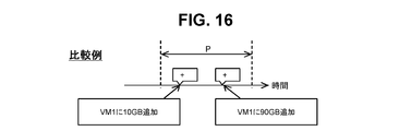
- An example of an actual configuration change according to a comparative example is shown.
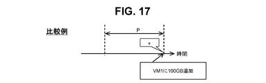
- An example of a configuration change detected in one comparative example is shown.
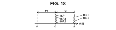
- An example of acquisition of an event record is shown.
- An example of acquisition of a change record is shown.
- An example of association of a change record with an event record is shown.
- the 1st example of the record unmatching concerning one comparative example is shown.
- the 2nd example of the record unmatching concerning one comparative example is shown.
- An example of change record virtualization is shown.
- An example of the effect of virtualization of a change record is shown.
- the “interface part” includes one or more interfaces.
- the one or more interfaces may be one or more similar interface devices (for example, one or more NIC (Network Interface Card)) or two or more different interface devices (for example, NIC and HBA (Host Bus Adapter)). There may be.
- NIC Network Interface Card
- HBA Home Bus Adapter
- the “processor unit” includes one or more processors.
- the at least one processor is typically a CPU (Central Processing Unit).
- the processor may include a hardware circuit that performs part or all of the processing.
- the process may be described using “program” as the subject, but the program is executed by the processor unit, so that the determined process can be appropriately performed in the storage unit and the interface unit.
- the subject of processing may be a processor unit (or a computer or a computer system having a processor unit).
- the program may be installed in the computer from a program source.
- the program source may be, for example, a program distribution server or a computer-readable recording medium.
- two or more programs may be realized as one program, or one program may be realized as two or more programs.
- information may be described using an expression such as “xxx table”, but the information may be expressed in any data structure. That is, in order to show that the information does not depend on the data structure, the “xxx table” can be referred to as “xxx information”.
- the configuration of each table is an example, and one table may be divided into two or more tables, or all or part of the two or more tables may be a single table. Good.
- the management system may be composed of one or more computers.
- the management computer displays information (specifically, the management computer displays information on its own display device, or the management computer transmits display information to a remote display computer)
- the management computer is the management system.
- the plurality of computers may include a display computer when the display computer performs display
- Input of information to the computer and output of information from the computer may be performed by an input / output device included in the computer. Examples of the input / output device include a display device, a keyboard, and a pointing device, but another device may be employed instead of or in addition to at least one of them.
- a serial interface device or an Ethernet interface device (Ethernet is a registered trademark) is adopted, and a display computer having a display device, a keyboard, and a pointer device is connected to such an interface device.
- the information may be output (for example, displayed) and input by the computer transmitting the display information to the display computer or the computer receiving the input information from the display computer.
- the management server 557 is a management computer
- the management client 555 is a display computer.
- element means a component of a computer system. Specifically, each of a plurality of nodes (devices) constituting the computer system and a plurality of components included in each node. Is a generic term for each of As a node, there are a physical node (for example, a network switch) and a logical node (for example, a virtual machine). Similarly, there are physical components (for example, a microprocessor) and logical components (for example, volume (logical volume)) as components.
- At least one term of “parent element”, “upper element”, “child element”, and “lower element” may be used to mean a relationship between elements.
- the “parent element” means an element that is one level higher than the element.
- “Upper element” means an element higher than the element. Therefore, the parent element is one of the upper elements.
- the “child element” means an element that is one level lower than the element.
- “Lower element” means an element lower than the element. Therefore, the child element is one of the lower elements. Since the relationship between elements is relative, it is natural to pay attention to whether each element is a “parent element”, “upper element”, “child element”, or “lower element”. It depends on the element.
- names or IDs are used as identification information, but they may be interchangeable with each other, and instead of or in addition to at least one of them, other types of identification Information may be used.
- the information collection start time is referred to as “polling time”. It is assumed that information is collected from each node in the computer system from the polling time (an example of the first collection start time) to the next polling time (an example of the second collection start time).
- Information collection may be a mixture of pull-type collection and push-type collection. Nodes involved in push-type collection may periodically provide information to the management system.
- FIG. 1 shows a configuration of a computer system and a management system according to the embodiment.
- the computer system 100 includes one or more servers 553 and one or more storage devices 551 connected to the one or more servers 553.
- a server 553 is connected to the storage device 551 via a communication network 521 (for example, SAN (Storage Area Network) or LAN (Local Area Network)).
- the communication network 521 may include a network switch as an example of a node.
- the storage apparatus 551 has a physical storage device group 563 and a controller 561 connected to the physical storage device group 563.
- the physical storage device group 563 has one or more PG (Parity Group).
- the PG may be referred to as a RAID (Redundant Array of Independent (or Inexpensive) Disks) group.
- the PG is composed of a plurality of physical storage devices, and stores data according to a predetermined RAID level.
- the physical storage device is, for example, an HDD (Hard Disk Drive) or an SSD (Solid State Drive).
- the storage device 551 has a plurality of logical volumes. As the logical volume, there is a substantive logical volume (real volume) 565 based on PG and a virtual logical volume (virtual volume) 567 according to thin provisioning or storage virtualization technology.
- One storage device 551 does not necessarily have a plurality of types of logical volumes.
- the storage apparatus 551 may have only the real volume 565 as the logical volume.
- a storage area is allocated from the pool to the virtual volume according to thin provisioning.
- the pool is a storage area group based on one or more physical storage devices (for example, PG), and may be a set of one or more logical volumes, for example.
- the pool may be a pool in which a difference between the original logical volume and its snapshot is stored instead of a pool having a storage area allocated to a virtual volume according to thin provisioning.
- the controller 561 includes a plurality of devices, for example, a port, an MPB (a blade (circuit board) having one or a plurality of microprocessors (MP)), and a cache memory.
- the port receives an I / O (Input / Output) command (write command or read command) from the server 553, and the MP included in the MPB controls I / O of data according to the I / O command.
- the MP specifies an I / O destination logical volume from the received I / O command, and performs data I / O on the specified logical volume. Data input / output to / from the logical volume is temporarily stored in the cache memory.
- the server 553 may be a physical computer or a virtual machine (virtual machine (VM)).
- the server 553 executes one or more application programs (APP) 552.
- APP application programs
- the computer system 100 has a plurality of hierarchical elements.
- the plurality of elements include elements of two or more element types such as APP 552, server 553, storage device 551, controller 561, port, MPB, cache memory, logical volume, and PG.
- a plurality of elements in the same layer may be grouped to define an element in a higher layer than the element in that layer.
- the “element” may be a substantial element such as an APP or a logical volume, or a virtual element that is a group of a plurality of substantial elements.
- the management system includes a management server 557 and one or more management clients 555 connected to the management server 557.
- a management client 555 is connected to the management server 557 via a communication network (for example, LAN, WAN (World Area Network) or the Internet) 521.
- a communication network for example, LAN, WAN (World Area Network) or the Internet
- the management client 555 includes an input device 501, a display device 1502, a storage device (for example, memory) 505, a communication interface device (hereinafter referred to as I / F) 507, and a processor (for example, a CPU (Central Processing Unit)) connected thereto. 503.
- the input device 501 is, for example, a pointing device and a keyboard.
- the display device 1502 is a device having a physical screen on which information is displayed, for example. A touch screen in which the input device 501 and the display device 1502 are integrated may be employed.
- the I / F 507 is connected to the communication network 521, and the management client 555 can communicate with the management server 557 via the I / F 507. A part or all of the communication network 521, the network connecting the server 553 and the storage device 551 may be common.
- the storage unit 505 includes, for example, at least a main storage device (typically a memory) of a main storage device and an auxiliary storage device.
- the storage unit 505 can store a computer program executed by the processor 1503 and information used by the processor 1503.
- the storage unit 505 stores a Web browser 511 and a management client program 513.
- the management client program 513 may be RIA (Rich Internet Application).
- the management client program 513 is a program file, and may be downloaded from the management server 557 (or another computer) and stored in the storage unit 505.
- the management server 557 includes a storage unit 535, an I / F 537, and a processor (for example, a CPU (Central Processing Unit)) 533 connected thereto.
- the I / F 537 is an example of an interface unit, is connected to the communication network 521, and the management server 557 can communicate with the management client 555 via the I / F 537.
- the management server 557 can receive an instruction in accordance with a user operation or display information via the I / F 537.
- the storage unit 535 includes, for example, at least a main storage device (typically a memory) of a main storage device and an auxiliary storage device.
- the storage unit 535 can store a computer program executed by the processor 533 and information used by the processor 533.
- the storage unit 535 stores a management server program 541 and management information 543.
- the management information 543 includes information representing a hierarchical relationship among a plurality of elements included in the computer system, failure information of each element, and the like. At least part of the management information 543 may be collected by the management server program 541.
- the management server program 541 receives an instruction in accordance with a user operation from the management client 555 and transmits display information to the management client 555.
- the management server program 541 performs matching determination between an event record described later and a change record described later (details will be described later).
- the processor 533 is an example of a processor unit. Display according to a user operation may be realized by cooperation processing of the management server program 541, the Web browser 511 (or the RIA execution environment of the client), and the management client program 513.
- management server 557 a first management server (configuration management server) that collects information from the computer system 100 and accumulates event records to be described later, and manual input regarding a configuration change of the computer system 100 (for example, a changer) )
- a second management server IT process management server
- a first management client (configuration management client) communicating with the first management server
- a second management client (IT process management) communicating with the second management server.
- Client There may be a plurality of at least one of the first management server, the second management server, the first management client, and the second client.
- FIG. 2 shows the configuration of the management information 543.
- Management information 543 includes configuration information 310, matching rule table 220, change table 230, and matching table 240.
- the configuration information 310 includes a node table 211, a node detail table 212, a component table 213, and a change event table 214.
- FIG. 3 shows the configuration of the node table 211.
- the node table 211 is a table that holds information about nodes.
- the node table 211 has a record for each node. Each record holds information such as a node ID 301, a node type 302, and a polling time 303.
- the node ID 301 is an identifier that uniquely identifies the node.
- the node type 302 represents a node type. Examples of the node type include a server computer (SERVER), a storage device (STORAGE), and a fiber channel switch (FCSWITCH).
- the fiber channel switch is an example of a network device.
- the polling time 303 is a collection start time of record information.
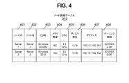
- FIG. 4 shows the configuration of the node detail table 212.
- the node detail table 212 is a table that holds detailed information regarding nodes.
- the node detail table 212 has a record for each node. Each record holds information such as a node ID 401, a node name 402, an OS name 403, a memory capacity 404, a CPU 405, a disk capacity 406, an IP address 407, and a polling time 408.
- the node ID 401 is an identifier that uniquely identifies the node.
- the node name 402 is the name of the node.
- the OS name 403 is the name of an OS (Operating System) executed on the node.
- the memory capacity 404 is a memory capacity of the node.
- the disk capacity 406 is the capacity of the disk that the node has.
- the IP address 407 is an IP address assigned to a node, and is an IP address used for collecting information from the node.
- the polling time 408 is a record information collection start time.
- the management server program 541 collects information from the computer system 100 at a polling interval.
- the node IP address is used to collect information from the node.
- Information acquired at a polling interval includes (a) information on an infrastructure element (an example of an element), (b) information on a component (an example of an element) constituting the infrastructure element, and (c) information on an infrastructure element or a component. , (D) information representing the relationship between infrastructure elements and components, etc.
- Specific examples of the information (a) are information on hypervisors, virtual machines, storage devices, and the like.
- a specific example of the information in (b) is information on a physical or virtual CPU, memory, NIC, disk, etc. managed by the hypervisor when the infrastructure element is a hypervisor.
- a specific example of the information (c) is information such as a vendor name, an OS name, a server name, a memory capacity, and a CPU clock number.
- a specific example of the information in (d) is information representing a connection relationship between the hypervisor and the virtual machine, a connection relationship between the hypervisor and the storage device, and the like. Based on the collected information, a record is added, deleted, or changed to at least one of the tables 211 to 214.
- FIG. 5 shows the configuration of the component table 213.
- the component table 213 is a table that holds information related to components included in a node.
- the component table 213 has a record for each component.
- Each record holds information such as a component ID 501, a component type 502, a component name 503, and a parent node ID 504.
- the component ID 501 is an identifier that uniquely identifies the component.
- the component type 502 is a component type. Examples of the component type include a LAN adapter (LAN_ADAPTER), an iSCSI disk (ISCSI_DISK), and an application (APPLICATION).
- the component name 503 is the name of the component.
- the parent node ID 504 is an identifier of a node having a component (component parent element).
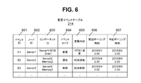
- FIG. 6 shows the configuration of the eyelid change event table 214.
- the change event table 214 is a table that holds information regarding events (configuration changes) that occur at the polling interval.
- the change event table holds a record for each event.
- the record of the change event table may be referred to as an “event record”.
- Each event record is an example of a configuration information entry.
- Each event record holds information such as event ID 601, node ID 602, component ID 603, event type 604, change contents 605, previous polling time 606 and current polling time 607.
- the event ID 601 is an identifier for uniquely identifying an event.
- the node ID 602 is an identifier of a node related to the event.
- the component ID 603 is an example of a detection element ID and is an identifier of a component related to an event.
- the event type 604 is an event type. Examples of the event type include a change, addition, or deletion to a component.
- the change content 605 is the content of the change made to the component. Specifically, for example, information X (an example of first information) collected at the previous polling time and the current polling time are collected. It is the content obtained from the difference from the information Y (an example of the second information) that is the information.
- the previous polling time 606 represents the previous polling time that is the polling polling time when the information X that is the basis of the configuration change represented by the record is collected.
- the previous polling time is an example of the first collection start time.
- the current polling time 607 represents the current polling time that is the polling time of polling when the information Y that is the basis of the configuration change represented by the record is collected. This polling time is an example of the second collection start time.
- the configuration change represented by the event record added by the management server program 541 in the Nth polling includes the second information collected by the Nth polling, the first information collected by the (N-1) th polling, This is a configuration change represented by the difference.
- the management server program 541 can identify the difference between the first information and the second information by comparing the second information with the first information.
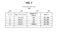
- FIG. 7 shows the configuration of the matching rule table 220.
- the matching rule table 220 is a table that holds information on matching rules.
- the matching rule table 220 holds a record for each matching rule.
- a record in the matching rule table 220 may be referred to as a “matching rule record”.
- Each matching rule record holds information such as a rule ID 701, a target component type 702, a virtual change record creation method 703, and a change type 704.
- the rule ID 701 is an identifier that uniquely identifies a matching rule.
- the target component type 702 is information for specifying a change record (to be described later) to which a matching rule is applied, and is a component type that performs a configuration change represented by the change record.
- a virtual change record creation method 703 represents a creation method of a virtual change record, and types thereof include “join”, “split”, and “split & join”.
- the change type 704 is information for specifying a change record to which the matching rule is applied, and is a change type. Examples of the type of change include “addition”, “deletion”, and “addition and deletion” with respect to the component.
- FIG. 8 shows the configuration of the change table 230.
- the change table 230 is a table that holds information related to configuration changes.
- the change table 230 has a record for each configuration change.
- a record in the change table 230 may be referred to as a “change record”.
- Each change record holds information such as a change ID 801, a component ID 802, a change type 803, a change content 804, and a change detail 805.
- At least the change details 805 among the component ID 802, the change type 803, the change contents 804, and the change details 805 are manually input information.
- Manual input may be text input or input according to various methods such as selection from a menu such as a pull-down menu.
- the change ID 801 is an identifier assigned to the change record.
- the component ID 802 is an identifier of a component whose configuration has been changed.
- the change type 803 is the type of configuration change that has been made. Examples of the change type include “change”, “add”, and “delete”.
- the change content 804 is specific content of the configuration change.
- the change details 805 are information related to the configuration change indicated by the change record, and are collected at the previous polling time that is the same as or older than the configuration change time indicated by the change record and the next current polling time. This information cannot be identified from the information.
- the change details 805 include a change time 811 among a change time 811, a title 812, a changer 813, an event ID 814, and the like.
- the change time 811 is the time of configuration change.
- the title 812 is a title for configuration change.
- the changer 813 is the ID of the person who changed the configuration.
- the event ID 814 is an event identifier as a configuration change represented by the change record.
- the change details 805 include, instead of or in addition to at least one of the items other than the change time 811, the purpose of the configuration change, the result of the configuration change, the importance of the configuration change, the cost of the configuration change, and the effect of the configuration change Further, an item (information) representing at least one of the contents of deliberation on whether or not to implement the configuration change and the relationship with other configuration changes (other change records) may be included.
- FIG. 9 shows the configuration of the matching table 240.
- the matching table 240 is a table that holds information relating to record association, which is an association between an event record and a change record.
- the matching table holds a record for each record association.
- a record held in the matching table may be referred to as a “matching record”.
- Each matching record holds information such as an event ID 901 and a change ID 902.
- the event ID 901 is an identifier that uniquely identifies an event record.
- the change ID 902 is an identifier that uniquely identifies the change record.
- each of the event ID and the change ID may be one or more, but typically one event ID and one or more change IDs are held.
- FIG. 10 shows the flow of the entire matching process.
- the entire matching process is a process for associating a change record with an event record, specifically, a process for creating a matching record.
- the management server program 541 acquires an event record belonging to the period T from the change event table 214 (S1001), and acquires a change record belonging to the period T from the change table 230 (S1002).
- the “period T” is a matching target period.
- the period T may be a period designated by a user (for example, an administrator).
- the period T is one or more polling periods. Each polling period is a period from the previous polling time to the next current polling time (however, this polling time is not included).
- Event record belonging to period T” is an event record including a previous polling time 606 and a current polling time 607 representing a polling period included in the period T.
- the “change record belonging to the period T” is a change record including a change time 811 representing the time included in the period T.
- Loop A is performed for all event records acquired in S1001.
- Loop B is performed for all the change records acquired in S1002.
- one event record (“target event record” in the description of FIGS. 10 to 15) and one change record (“target change record” in the descriptions of FIGS. 10 and 11) are taken as examples.
- the management server program 541 determines whether the event ID 601 in the target event record matches the event ID 814 in the target change record (S1003).
- S1007 determination of whether or not matching is performed
- the determination result in S1007 is also true (S1007: YES)
- the management server program 541 uses the event ID 601 in the target event record and the change ID 801 in the target change record as the event ID 901 and the change ID 902, respectively, as a matching table. It is registered in 240 matching records (S1008).
- the management server program 541 executes a change content match confirmation process (S1004).
- the management server program 541 determines S1007 (determination of matching). Is done. In this case, the determination result in S1007 is also true (S1007: YES), and the management server program 541 uses the event ID 601 in the target event record and the change ID 801 in the target change record as the event ID 901 and the change ID 902, respectively, as a matching table. It is registered in 240 matching records (S1008).
- the management server program 541 executes S1007 (determination of matching).
- S1007 determination of matching
- the management server program 541 determines the event ID 601 in the target event record and one or more changes in one or more change records determined to match the target event record.
- ID 801 is registered in the matching record of matching table 240 as event ID 901 and change ID 902, respectively.
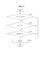
- FIG. 11 shows the flow of the change content match confirmation process (S1004 in FIG. 10).
- the management server program 541 determines whether or not the component ID 603 in the target event record matches the component ID 802 in the target change record (S1101).
- the management server program 541 determines whether or not the event type 604 in the target event record matches the change type 803 in the target change record (S1102). .
- the management server program 541 determines whether or not the change content 605 in the target event record matches the change content 804 in the target change record (S1103). .
- the management server program 541 If the determination result of S1103 is true (S1103: YES), the management server program 541 returns a result of matching (S1104). On the other hand, if any of the determination results in S1101 to S1103 is false, the management server program 541 returns a result of mismatch (S1104).
- FIG. 12 shows the flow of the matching determination process (S1006 in FIG. 10).
- the management server program 541 acquires the matching rule table 220 (S1201), and acquires the component type 502 corresponding to the component ID 603 in the target event record from the component table 213 (S1202). Specifically, for example, when the target event record is an event record including the event ID “E2”, the component ID 603 is “Server2 / Memory2” (see FIG. 6). The component type 502 corresponding to the component ID 603 is “MEMORY” (see FIG. 5).
- the management server program 541 searches the matching rule table 220 for a matching rule record corresponding to the target component type 702 that matches the acquired component type 502 (S1203). For example, when the acquired component type 502 is “MEMORY”, the matching rule record corresponding to the target component type 702 “MEMORY” includes three matchings each including “R2”, “R3”, and “R4” as the rule ID 701. It is a rule record (see FIG. 7).
- the management server program 541 If there is no matching rule record that matches as a result of S1203 (S1204: NO), the management server program 541 returns a matching failure (S1212).
- the management server program 541 executes loop C for all matching rule records.
- one matching rule record (“target rule record” in the description of FIGS. 12 to 15) is taken as an example.
- the management server program 541 executes the join matching process (S1208). For example, when the target rule record is a record including the rule ID 701 “R1”, since the virtual change record creation method 703 is “join”, the join matching process is executed.
- the management server program 541 executes division matching processing (S1209). For example, when the target rule record is a record including the rule ID 701 “R2”, since the virtual change record creation method 703 is “divided”, the division matching process is executed.
- the management server program 541 executes a split & join matching process (S1210).
- the target rule record is a record including the rule ID 701 “R4”
- the virtual change record creation method 703 is “divide & join”
- the split & join matching process is executed.
- the management server program 541 when matching is successful (S1211: YES), the management server program 541 returns matching success for the target event record (S1212). On the other hand, when matching fails for any matching rule record for the target event record, the management server program 541 returns matching failure for the target event record (S1212).
- FIG. 13 shows the flow of the joint matching process.
- the management server program 541 searches for a change record including a component ID 802 and a change type 803 that respectively match the component ID 603 in the target event record and the change type 704 in the target rule record (S1301).
- the management server program 541 creates one virtual change record by combining the change contents 804 in all the found change records (S1303). . For example, if there is a change record for adding 1 TB to the same disk as the change record for adding 500 GB to the disk “Sever1 / iSCSI_Disk1”, the management server program 541 combines 500 GB and 1 TB to obtain Sever1 / iSCSI_Disk1. Create one virtual change record that adds 1.5TB to the disk.
- the configuration of the change content 804 in the change record adopts a configuration including content types such as “add” and “delete” and parameters (numerical values) such as “500 GB” and “1 TB”. can do. It is possible to combine (eg, add) a plurality of parameters corresponding to the same content type.
- the management server program 541 determines whether or not the change content 605 in the target event record matches the change content in the virtual change record created in S1303 (S1304). If the determination result in S1304 is false (S1304: NO), the management server program 541 returns a matching failure (S1305). If the determination result in S1304 is true (S1304: YES), the management server program 541 returns matching success (S1305).
- FIG. 14 shows the flow of the division matching process.
- the management server program 541 acquires a change record that satisfies all the following conditions (S1401).
- a change record including a plurality of identifiers as the component ID 802.
- a change record that includes a component ID 802 that includes an identifier that matches the component ID 603 in the target event record.
- the management server program 541 If no change record is acquired in S1401 (S1402: NO), the management server program 541 returns a matching failure (S1407).
- the management server program 541 creates a virtual change record for each of a plurality of change contents (a plurality of change contents in the change contents 804) respectively corresponding to a plurality of identifiers included in the component ID 802 in the target change record.
- the configuration of the virtual change record is the same as the configuration of the change record. That is, the virtual change record includes the same items as the items included in the change record.
- the management server program 541 deletes 8G from “Server2 / Memory2” and 8G from the virtual change record “Server2 / Memory3”. And create a virtual change record. Thereafter, loop E is performed for all the created virtual change records.
- one virtual change record (“target virtual change record” in the description of FIG. 14) is taken as an example.
- S1404 to S1406 in the loop E are the same processes as S1101 to S1103 in FIG.
- the management server program 541 determines whether or not the component ID 603 in the target event record matches the component ID in the target virtual change record (S1404).
- the management server program 541 determines whether or not the event type 604 in the target event record matches the change type in the target virtual change record (S1405). .
- the management server program 541 determines whether or not the change content in the target event record matches the change content in the target virtual change record (S1406).
- S1406 If the determination result of S1406 is true (S1406: YES), the management server program 541 returns a result of successful matching (S1407).
- FIG. 15 shows the flow of split & join matching processing.
- S1501 to S1503 are performed.
- S1501 to S1503 are the same as S1401 to S1403 in FIG.
- Steps S1504 to S1508 are the same as steps S1301 to S1305 in FIG.
- the “change record” is either a change record or a virtual change record.
- matching success / matching failure is returned instead of match / mismatch.
- the management server program 541 collects information about the configuration from the computer system 100 at a polling interval.
- the management server program 541 compares the information collected in the current polling period with the information collected in the previous polling period. If there is a difference between these pieces of information, the management server program 541 can create one or more event records (an example of a configuration information entry) respectively corresponding to one or more configuration changes identified from the difference. Instead of comparing the information collected during the current polling period with the information collected during the previous polling period, the collected information contains information equivalent to an event record, and at least one of the information The part may be registered as at least a part of the event record.
- the identified configuration change can be used for investigation when a failure occurs in the computer system 100, identification of an influence range, and the like.
- “Large scale” means that the number of elements to be managed in the computer system, such as nodes constituting the computer system and components of the node, has increased.
- “complication” means that the relationship between elements becomes M: 1, 1: N, M: N as the types of managed elements increase (M and N are integers of 2 or more, respectively) ), At least one of the values of at least one of M and N increases, and the relationship between elements changes from moment to moment.
- the polling interval is determined based on the scale of the computer system 100 (specifically, the amount of information (amount of information to be collected) depending on the scale of the computer system 100).
- the polling interval is a long interval (for example, “1 day”). This is because it takes a long time for one polling (information collection).
- the configuration of the computer system may be changed multiple times during a certain polling period.
- a configuration change can be detected from a comparison between information collected during the current polling period and information collected during the previous polling period. Details of the detected configuration change (for example, detection) Whether the configuration change made is the result of one configuration change or the result of multiple configuration changes) is not known. For example, as illustrated in FIG. 16, even when the capacity of the VM 1 (virtual machine 1) is changed multiple times in a certain polling period P (for example, 10 GB and 90 GB are added twice). 17), as illustrated in FIG. 17, it is recognized that the capacity change has been performed once (it is recognized that one addition such as addition of 100 GB has been performed).
- the user when a configuration change is made, the user (for example, the changer (the person who performed the configuration change)) changes to the management server (for example, the IT process management server of the configuration management server and the IT process management server).
- Register a record an example of a change information entry.
- the user manually inputs information regarding the details of the configuration change, and a change record (ticket) including at least a part of the manually input information is registered.
- Some information in the change record may be automatically entered information.
- the purpose of registering change records is, for example, to ensure that standardized methods and procedures are used to make all configuration changes efficiently and quickly, and to prevent problems arising from the changes. This is to avoid it.
- the change record includes the component ID 802, the change type 803, and the change content 804. Further, the change record includes the change details 805 including the change time 811 as described above. As described above, the change details 805 include the purpose of the configuration change, the result of the configuration change, the importance of the configuration change, and the cost for the configuration change, instead of or in addition to at least one of the items other than the change time 811. In addition, an item (information) representing at least one of the influence of the configuration change, the contents of deliberation on whether or not to implement the configuration change, and the relationship with another configuration change (other change record) may be included.
- the event record can be mechanically (automatically) acquired for each polling period based on the difference between the information collected during the polling period and the information collected during the previous polling period.
- the event records 18A1, 18A2, 18A3,... Are records acquired based on information collected in the polling period P1 and information collected in the previous polling period (not shown).
- the event records 18B1, 18B2,... Are records acquired based on the information collected in the polling period P2 and the information collected in the previous polling period P1.
- the polling period P1 is a period from polling time t1 to polling time t2 (not including t2), and the polling period P2 is a period from polling time t2 to polling time t3 (however, not including t3).
- Each polling period has a length corresponding to the polling interval.
- the change record is registered when a configuration change is made and does not depend on the polling interval.
- each of the change records 19A to 19E is registered by a user (or another user (eg, an administrator)) when the configuration change is made by the user (eg, a changer).
- an event record is a record that is automatically acquired based on information collected at a polling interval. From this point of view, it can be said that there is completeness.
- the change record includes detailed information including information that cannot be specified from the collected information, but it may not be registered due to forgetting to input even if the configuration is changed. It can be said that there is no.
- the management server program 541 has one or more items in a relatively coarse but comprehensive event record, and one or more items in a change record that is not complete but relatively detailed.
- change records 19A, 19B, and 19C are associated with event records 18A1, 18A2, and 18A3, respectively
- change records 19D and 19E are associated with event records 18B1 and 18B2, respectively.
- the user for example, administrator
- the change record is associated with the event record
- the following two can be considered.
- (Advantage 2) When the computer system 100 is large-scale or complicated, it is considered that many change records are registered. However, the change records can be narrowed down by using event records, and therefore, the necessary change records are identified. Easy to do.
- the change record 19X1 indicating “10 GB added to VM1” and the change record 19X2 indicating “90 GB added to VM1” are “100 GB to VM1”.
- each of the change records 19X1 and 19X2 corresponds to the event record 18X indicating “addition”, 1: 1 does not correspond to the event record 18X. That is, it is not known from the event record 18X that the capacity has been added twice.
- the management server program 541 in order to match the event record 18 and the change record 19 even in the case illustrated in FIGS. 21 and 22, the management server program 541 has a matching rule table as shown in FIG. 23.
- the matching determination process using S220 (S1006 in FIG. 10) is executed.
- a virtual change record 23 in which at least a part of one or more change records 19 is virtualized is created, and the management server program 541 uses the virtual change record 23 as a basis for the virtual change record 23 1
- One or more event records 18 related to the above change records can be specified. Specifically, for example, as illustrated in FIG.
- the management server program 541 creates a virtual change record 23X representing “100 GB added to VM1” by combining the above-described change records 19X1 and 19X2.
- “100 GB” in the virtual change record 23X is the sum of “10 GB” in the change record 19X1 and “90 GB” in the change record 19X2.
- the virtual change record 23X obtained by virtualizing the change records 19X1 and 19X2 matches the event record 18X.
- the change record 19 virtualization method includes not only “join” but also other kinds of virtualization methods such as “split” and “split & join”.
- “join” can be adopted as the virtualization method.
- the virtualization method “ The virtual change record 23 for moving VM1 from HV # 1 to HV # 2 cannot be created only by “join”. Therefore, by adopting a “divide & join” which is a virtualization method of splitting and combining one change record, and performing a matching determination using the virtual change record 23 created according to the virtualization method, Appropriate matching can be performed.
- the change record 19 includes change details 805 including a change time 811 in addition to the component ID 802, the change type 803, and the change content 804. Such a change record 19 is associated with the event record 18.
- the management server program 541 identifies a change record associated with the event record, information represented by the event record, and information represented by the identified change record associated with the event record (the event record does not have Information including at least a part of detailed information).
- a user eg, an administrator who has viewed the displayed information can know at least one of the following, for example.
- Each change time of one or more actual configuration changes corresponding to the event record 18 For each of one or more actual configuration changes corresponding to the event record 18, the changer and the reason for the configuration change.
- the infrastructure is the computer system 100 with a plurality of users.
- users there are users (infrastructure users), changers (infrastructure operators or specialized engineers), and administrators (infrastructure administrators).
- the change timing of the infrastructure is arbitrary. Specifically, a user is added (for example, a node to be managed is added) or a node configuration is changed at the request of the user, but the timing is arbitrary. For this reason, infrastructure changes are usually made by a changer rather than an administrator, or a system that automatically changes infrastructure is used. Administrators do not always monitor changes in real time.
- the reason for the change can be used to examine how to deal with the failure. For example, the priority to deal with can be determined from the importance of the customer.
- the granularity of measures can be finely adjusted. Specifically, for example, it is 100 GB in terms of configuration management, but it is also possible to restore only 10 GB by dividing the change into 90 GB and 10 GB.
Landscapes
- Engineering & Computer Science (AREA)
- Theoretical Computer Science (AREA)
- Physics & Mathematics (AREA)
- General Engineering & Computer Science (AREA)
- General Physics & Mathematics (AREA)
- Software Systems (AREA)
- Quality & Reliability (AREA)
- Human Computer Interaction (AREA)
- Computing Systems (AREA)
- Computer Vision & Pattern Recognition (AREA)
- Computer And Data Communications (AREA)
- Debugging And Monitoring (AREA)
- Information Retrieval, Db Structures And Fs Structures Therefor (AREA)
Abstract
管理システムが、複数の構成情報エントリと複数の変更情報エントリとを保持する。複数の構成情報エントリの各々は、計算機システムから定期的に収集された情報に含まれている情報と、計算機システムから第1及び第2の収集においてそれぞれ収集された第1及び第2の情報に基づいて特定された情報とのうちの少なくとも一部を含み、計算機システムの構成変更を表す情報である。複数の変更情報エントリの各々は、計算機システムの構成変更に関して手動で入力された情報を含み、計算機システムの構成変更を表す情報である。管理システムは、複数の構成情報エントリのうちの少なくとも1つに複数の変更情報エントリのうちの少なくとも1つを対応付けて管理する。
Description
本発明は、概して、計算機システムの管理に関する。
計算機システムの管理技術として、例えば特許文献1が知られている。特許文献1では、以下の処理が行われる。すなわち、管理対象コンピュータ上に常駐のエージェントが、当該管理対象コンピュータの資源が変更したことの検知を契機に、その資源変化の内容を、運用管理サーバ上のマネージャへ通知する。運用管理サーバの変更計画DB(データベース)には、各管理対象コンピュータについての個々の資源変更の計画について、その計画された資源変更の内容が、登録されている。マネージャは、エージェントから通知された資源変化の内容が、変更計画DBに登録されている資源変更の計画通りであるかどうかをチェックし、計画通りであれば、変更計画DBに登録されている資源変更が計画通り完了した旨を登録する。
計算機システムの管理システムとして、計算機システムからポーリング間隔で(定期的に)情報を収集する管理システムが知られている。収集される情報は、一般に、計算機システムの構成情報である。構成情報は、計算機システムの構成に関する情報である。
ポーリング間隔は、計算機システムの規模(具体的には、計算機システムの規模に依存する情報量(収集対象の情報の量))に基づいて決定される。計算機システムの規模によって、ポーリング間隔は長い間隔(例えば「1日」)とされる。1回の情報収集に長い時間がかかってしまうからである。
ポーリング間隔が長い場合、或るポーリング期間(或るポーリングの開始時刻から次のポーリングの開始時刻まで(但し次のポーリング時刻を含まない))の間に複数回にわたって計算機システムの構成が変更されることがある。今回のポーリング期間に収集された情報と前回のポーリング期間に収集された情報との比較から、構成変更を検出し得るが、検出された構成変更の詳細(例えば、検出された構成変更が1回の構成変更の結果であるのか複数回の構成変更の結果であるのか)は、わからない。これにより、少なくとも1つの問題、例えば、いずれかの構成変更が原因で計算機システムに障害が生じても障害原因の構成変更がわからず障害対応に時間がかかってしまうといった問題が生じ得る。
このような問題は、情報の収集のタイプが、ポーリングのようなプル型に限らず、計算機システムが管理システムからの問合せ無しに情報を提供するプッシュ型であってもあり得る。
管理システムが、複数の構成情報エントリと複数の変更情報エントリとを保持する。複数の構成情報エントリの各々は、計算機システムから定期的に収集された情報に含まれている情報と、計算機システムから第1及び第2の収集においてそれぞれ収集された第1及び第2の情報に基づいて特定された情報とのうちの少なくとも一部を含み、計算機システムの構成変更を表す情報である。複数の変更情報エントリの各々は、計算機システムの構成変更に関して手動で入力された情報を含み、計算機システムの構成変更を表す情報である。管理システムは、複数の構成情報エントリのうちの少なくとも1つに複数の変更情報エントリのうちの少なくとも1つを対応付けて管理する。
収集のタイプは、プル型(管理システムからの問合せに応答して計算機システムから情報を受信すること)であってもよいし、プッシュ型(管理システムからの問合せ無しに計算機システムから情報を受信すること)であってもよい。前者の場合、情報の収集の間隔(周期)は、ポーリング間隔である。
複数の構成情報エントリは、それぞれ、定期的に収集された情報に基づく情報、すなわち、機械的に収集された情報から得られた情報であり、故に、収集開始時刻での構成と次の収集開始時刻での構成との差分を全て構成変更として特定できるという網羅性がある。一方、複数の変更情報エントリは、それぞれ、手動で入力された情報を含んだ情報であり、故に、個々の構成変更に関してより詳細な情報が得られる。複数の構成情報エントリのうちの少なくとも1つに、複数の変更情報エントリのうちの少なくとも1つが対応付けられる。このため、機械的に得られた情報が表す構成変更についての詳細をユーザ(例えば管理者)が知ることができる。
以下の説明では、「インターフェース部」は、1以上のインターフェースを含む。1以上のインターフェースは、1以上の同種のインターフェースデバイス(例えば1以上のNIC(Network Interface Card))であってもよいし2以上の異種のインターフェースデバイス(例えばNICとHBA(Host Bus Adapter))であってもよい。
また、以下の説明では、「プロセッサ部」は、1以上のプロセッサを含む。少なくとも1つのプロセッサは、典型的には、CPU(Central Processing Unit)である。プロセッサは、処理の一部または全部を行うハードウェア回路を含んでもよい。
また、以下の説明では、「プログラム」を主語として処理を説明する場合があるが、プログラムは、プロセッサ部によって実行されることで、定められた処理を、適宜に記憶部及びインターフェース部のうちの少なくとも1つを用いながら行うため、処理の主語が、プロセッサ部(或いは、プロセッサ部を有する計算機又は計算機システム)とされてもよい。プログラムは、プログラムソースから計算機にインストールされてもよい。プログラムソースは、例えば、プログラム配布サーバ又は計算機が読み取り可能な記録媒体であってもよい。また、以下の説明において、2以上のプログラムが1つのプログラムとして実現されてもよいし、1つのプログラムが2以上のプログラムとして実現されてもよい。
また、以下の説明では、「xxxテーブル」といった表現にて情報を説明することがあるが、情報は、どのようなデータ構造で表現されていてもよい。すなわち、情報がデータ構造に依存しないことを示すために、「xxxテーブル」を「xxx情報」と言うことができる。また、以下の説明において、各テーブルの構成は一例であり、1つのテーブルは、2以上のテーブルに分割されてもよいし、2以上のテーブルの全部又は一部が1つのテーブルであってもよい。
また、以下の説明では、同種の要素を区別して説明する場合は、その要素の参照符号を使用し(例えば、イベントレコード18A1、18A2、…、18B1、18B2、…)、同種の要素を区別しないで説明する場合は、その要素の参照符号のうちの共通符号のみ使用する(例えば、イベントレコード18、18A又は18B)ことがある。
また、以下の説明では、管理システムは、1以上の計算機で構成されてよい。具体的には、例えば、管理計算機が情報を表示する場合(具体的には、管理計算機が自分の表示デバイスに情報を表示する、或いは、管理計算機が表示用情報を遠隔の表示用計算機に送信する場合)、管理計算機が管理システムである。また、例えば、複数の計算機で管理計算機と同等の機能が実現されている場合は、当該複数の計算機(表示を表示用計算機が行う場合は表示用計算機を含んでよい)が、管理システムである。計算機への情報の入力や、計算機からの情報の出力は、計算機が有する入出力デバイスにより行われてよい。入出力デバイスの例としては、表示デバイス、キーボード及びポインティングデバイスが考えられるが、これらのうちの少なくとも1つに代えて又は加えて別のデバイスが採用されてよい。また、入出力デバイスの代替として、シリアルインターフェースデバイスやイーサーネットインターフェースデバイス(イーサネットは登録商標)が採用され、そのようなインターフェースデバイスに、表示デバイスとキーボード及びポインタデバイスとを有する表示用計算機が接続され、計算機が表示用情報を表示用計算機に送信したり、計算機が入力用情報を表示用計算機から受信したりすることで、情報の出力(例えば表示)及び入力が行われてよい。以下の説明では、管理サーバ557が、管理計算機であり、管理クライアント555が、表示用計算機である。
また、以下の説明では、「エレメント」とは、計算機システムの構成要素を意味し、具体的には、計算機システムを構成する複数のノード(装置)の各々、及び、各ノードが有する複数のコンポーネントの各々の総称である。ノードとして、物理的なノード(例えばネットワークスイッチ)もあれば論理的なノード(例えば仮想マシン)もある。同様に、コンポーネントとして、物理的なコンポーネント(例えばマイクロプロセッサ)もあれば論理的なコンポーネント(例えばvolume(論理ボリューム))もある。
また、以下の説明では、エレメント間の関係を意味するために、「親エレメント」、「上位エレメント」、「子エレメント」及び「下位エレメント」のうちの少なくとも1つの用語を使用することがある。「親エレメント」とは、エレメントの1つ上位のエレメントを意味する。「上位エレメント」とは、エレメントより上位のエレメントを意味する。従って、親エレメントは、上位エレメントのうちの1つである。「子エレメント」とは、エレメントの1つ下位のエレメントを意味する。「下位エレメント」とは、エレメントより下位のエレメントを意味する。従って、子エレメントは、下位エレメントのうちの1つである。エレメント間の関係は、相対的なものであるため、各エレメントが、「親エレメント」、「上位エレメント」、「子エレメント」及び「下位エレメント」のいずれになるかは、当然に、着目されるエレメントによって変わる。
また、以下の説明では、識別情報として、名前或いはIDが使用されるが、それらは相互に置換可能であってもよいし、それらのうちの少なくとも1つに代えて又は加えて他種の識別情報が使用されてもよい。
また、以下の説明では、計算機システムからの情報の収集は、プル型及びプッシュ型のうちのプル型であるとし、ポーリングであるとする。情報の収集開始時刻を、「ポーリング時刻」と言うことにする。ポーリング時刻(第1の収集開始時刻の一例)から次のポーリング時刻(第2の収集開始時刻の一例)までに、計算機システムにおける各ノードから情報が収集されるとする。なお、情報の収集は、プル型の収集とプッシュ型の収集とが混在していてもよい。プッシュ型の収集に関わるノードは、定期的に、情報を管理システムに提供してよい。
図1は、実施形態に係る計算機システム及び管理システムの構成を示す。
計算機システム100は、1以上のサーバ553と、1以上のサーバ553に接続された1以上のストレージ装置551とを含む。ストレージ装置551には、例えば、通信ネットワーク521(例えばSAN(Storage Area Network)又はLAN(Local Area Network))を介してサーバ553が接続される。通信ネットワーク521は、例えば、ノードの一例としてネットワークスイッチを含んでよい。
ストレージ装置551は、物理記憶デバイス群563と、物理記憶デバイス群563に接続されたコントローラ561とを有する。
物理記憶デバイス群563は、1以上のPG(Parity Group)を有する。PGは、RAID(Redundant Array of Independent (or Inexpensive) Disks)グループと呼ぶこともある。PGは、複数の物理記憶デバイスで構成されており、所定のRAIDレベルに従いデータを記憶する。物理記憶デバイスは、例えば、HDD(Hard Disk Drive)或いはSSD(Solid State Drive)である。
ストレージ装置551は、複数の論理ボリュームを有する。論理ボリュームとしては、PGに基づく実体的な論理ボリューム(実ボリューム)565もあれば、シンプロビジョニング或いはストレージ仮想化技術に従う仮想的な論理ボリューム(仮想ボリューム)567もある。1つのストレージ装置551が必ずしも複数種類の論理ボリュームを有さないでよい。例えば、ストレージ装置551は、論理ボリュームとして、実ボリューム565のみを有してもよい。シンプロビジョニングに従う仮想ボリュームにはプールから記憶領域が割り当てられる。プールは、1以上の物理記憶デバイス(例えばPG)に基づく記憶領域群であり、例えば、1以上の論理ボリュームの集合でよい。プールは、シンプロビジョニングに従う仮想ボリュームに割り当てられる記憶領域を有するプールに代えて、オリジナルの論理ボリュームとそのスナップショットとの差分が格納されるプールでもよい。
コントローラ561は、複数のデバイス、例えば、ポート、MPB(1又は複数のマイクロプロセッサ(MP)を有するブレード(回路基板))及びキャッシュメモリを有している。例えば、ポートが、サーバ553からI/O(Input/Output)コマンド(ライトコマンド又はリードコマンド)を受信し、MPBが有するMPが、そのI/Oコマンドに従うデータのI/Oを制御する。具体的には、例えば、MPは、受信したI/OコマンドからI/O先の論理ボリュームを特定し、特定した論理ボリュームに対してデータのI/Oを行う。論理ボリュームに対して入出力されるデータは、一時的に、キャッシュメモリに格納される。
サーバ553は、物理計算機でも仮想計算機(仮想マシン(VM))でもよい。サーバ553で、1以上のアプリケーションプログラム(APP)552が実行される。APP552が実行されることにより、論理ボリュームを指定したI/Oコマンドがサーバ553からストレージ装置551に送信する。
以上のように、計算機システム100は、階層的な複数のエレメントを有する。複数のエレメントは、具体的には、APP552、サーバ553、ストレージ装置551、コントローラ561、ポート、MPB、キャッシュメモリ、論理ボリューム及びPG等のうちの2つのエレメントタイプ以上のエレメントを含む。同じレイヤの複数のエレメントがグループ化されることでそのレイヤのエレメントより上位レイヤのエレメントが定義されてもよい。「エレメント」は、APPや論理ボリュームのような実体的なエレメントと、複数の実体的なエレメントのグループである仮想的なエレメントとがあってよい。
管理システムは、管理サーバ557と、管理サーバ557に接続された1以上の管理クライアント555とを含む。管理サーバ557には、通信ネットワーク(例えばLAN、WAN(World Area Network)又はインターネット)521を介して、管理クライアント555が接続される。
管理クライアント555は、入力デバイス501、表示デバイス1502、記憶デバイス(例えばメモリ)505、通信インターフェースデバイス(以下、I/F)507、及び、それらに接続されたプロセッサ(例えばCPU(Central Processing Unit))503を有する。入力デバイス501は、例えば、ポインティングデバイス及びキーボードである。表示デバイス1502は、例えば、情報が表示される物理画面を有するデバイスである。入力デバイス501及び表示デバイス1502が一体となったタッチスクリーンが採用されてもよい。I/F507は、通信ネットワーク521に接続され、I/F507を介して、管理クライアント555は管理サーバ557と通信することができる。なお、通信ネットワーク521と、サーバ553とストレージ装置551と、を接続するネットワークとは一部または全てが共通であってもよい。
記憶部505は、例えば、主記憶デバイス及び補助記憶デバイスのうちの少なくとも主記憶デバイス(典型的にはメモリ)を有する。記憶部505は、プロセッサ1503で実行されるコンピュータプログラム、及び、プロセッサ1503に使用される情報を記憶することができる。具体的には、例えば、記憶部505は、Webブラウザ511、及び、管理クライアントプログラム513を記憶する。管理クライアントプログラム513は、RIA(Rich Internet Application)でよい。具体的には、例えば、管理クライアントプログラム513は、プログラムファイルであり、管理サーバ557(或いは他の計算機)からダウンロードされ、記憶部505に記憶されてよい。
管理サーバ557は、記憶部535、I/F537、及び、それらに接続されたプロセッサ(例えばCPU(Central Processing Unit))533を有する。I/F537は、インターフェース部の一例であり、通信ネットワーク521に接続され、I/F537を介して、管理サーバ557は管理クライアント555と通信することができる。管理サーバ557は、I/F537を介して、ユーザ操作に従う指示を受信したり、情報を表示したりすることができる。
記憶部535は、例えば、主記憶デバイス及び補助記憶デバイスのうちの少なくとも主記憶デバイス(典型的にはメモリ)を有する。記憶部535は、プロセッサ533で実行されるコンピュータプログラム、及び、プロセッサ533に使用される情報を記憶することができる。具体的には、例えば、記憶部535は、管理サーバプログラム541及び管理情報543を記憶する。管理情報543は、計算機システムが有する複数のエレメントの階層関係を表す情報や、各エレメントの障害情報等を含む。管理情報543の少なくとも一部の情報は、管理サーバプログラム541により収集されてよい。管理サーバプログラム541は、ユーザ操作に従う指示を管理クライアント555から受信したり、表示用情報を管理クライアント555に送信したりする。また、管理サーバプログラム541は、後述のイベントレコードと後述の変更レコードとのマッチング判定を行う(詳細は後述)。プロセッサ533は、プロセッサ部の一例である。管理サーバプログラム541と、Webブラウザ511(またはクライアントのRIA実行環境)と、管理クライアントプログラム513と、の連携処理によって、ユーザ操作に応じた表示が実現されてよい。
なお、図1では、説明の簡単のために、管理サーバ557及び管理クライアント555はそれぞれ1つのみ図示しているが、管理サーバ557及び管理クライアント555の各々が複数存在してもよい。例えば、管理サーバ557として、計算機システム100から情報を収集して後述のイベントレコードを蓄積する第1の管理サーバ(構成管理サーバ)と、計算機システム100の構成変更に関する手動入力をユーザ(例えば変更者)から受け付けて後述の変更レコードを蓄積する第2の管理サーバ(ITプロセス管理サーバ)とが存在してもよい。同様に、管理クライアント555として、第1の管理サーバと通信する第1の管理クライアント(構成管理用の管理クライアント)と、第2の管理サーバと通信する第2の管理クライアント(ITプロセス用の管理クライアント)とが存在してもよい。第1の管理サーバ、第2の管理サーバ、第1の管理クライアント及び第2のクライアントのうちの少なくとも1つが複数存在してもよい。
図2は、管理情報543の構成を示す。
管理情報543は、構成情報310、マッチングルールテーブル220、変更テーブル230及びマッチングテーブル240を含む。構成情報310は、ノードテーブル211、ノード詳細テーブル212、コンポーネントテーブル213及び変更イベントテーブル214を含む。
図3は、ノードテーブル211の構成を示す。
ノードテーブル211は、ノードに関する情報を保持するテーブルである。ノードテーブル211は、ノード毎にレコードを有する。各レコードは、ノードID301、ノードタイプ302及びポーリング時刻303といった情報を保持する。
ノードID301は、ノードを一意に識別する識別子である。ノードタイプ302は、ノードのタイプを表す。ノードのタイプとしては、例えば、サーバ計算機(SERVER)、ストレージ装置(STORAGE)及びファイバチャネルスイッチ(FCSWITCH)等がある。ファイバチャネルスイッチは、ネットワーク装置の一例である。ポーリング時刻303は、レコードの情報の収集開始時刻である。
図4は、ノード詳細テーブル212の構成を示す。
ノード詳細テーブル212は、ノードに関する詳細の情報を保持するテーブルである。ノード詳細テーブル212は、ノード毎にレコードを有する。各レコードは、ノードID401、ノード名402、OS名403、メモリ容量404、CPU405、ディスク容量406、IPアドレス407及びポーリング時刻408といった情報を保持する。
ノードID401は、ノードを一意に識別する識別子である。ノード名402は、ノードの名前である。OS名403は、ノードで実行されるOS(Operating System)の名前である。メモリ容量404は、ノードが有するメモリの容量である。ディスク容量406は、ノードが有するディスクの容量である。IPアドレス407は、ノードに割り振られたIPアドレスであり、そのノードから情報を収集するために使用されるIPアドレスである。ポーリング時刻408は、レコードの情報の収集開始時刻である。
管理サーバプログラム541は、ポーリング間隔で計算機システム100から情報を収集するが、その際、ノードからの情報収集のためにノードのIPアドレスを用いる。また、ポーリング間隔で取得される情報は、(a)インフラエレメント(エレメントの一例)の情報、(b)インフラエレメントを構成するコンポーネント(エレメントの一例)の情報、(c)インフラエレメント又はコンポーネントに関する情報、(d)インフラエレメント及びコンポーネント間の関連性を表す情報、等である。(a)の情報の具体例は、ハイパーバイザ、仮想マシン及びストレージ装置等の情報である。(b)の情報の具体例は、インフラエレメントがハイパーバイザの場合、ハイパーバイザが管理する物理的又は仮想的なCPU、メモリ、NIC及びディスク等の情報である。(c)の情報の具体例は、ベンダ名、OS名、サーバ名、メモリ容量及びCPUクロック数等の情報である。(d)の情報の具体例は、ハイパーバイザと仮想マシン間の接続関係やハイパーバイザとストレージ装置間の接続関係等を表す情報である。収集された情報を基に、テーブル211~214の少なくとも1つに対して、レコードの追加、削除又は変更が行われる。
図5は、コンポーネントテーブル213の構成を示す。
コンポーネントテーブル213は、ノードが有するコンポーネントに関する情報を保持するテーブルである。コンポーネントテーブル213は、コンポーネント毎にレコードを有する。各レコードは、コンポーネントID501、コンポーネントタイプ502、コンポーネント名503及び親ノードID504といった情報を保持する。
コンポーネントID501は、コンポーネントを一意に識別する識別子である。コンポーネントタイプ502は、コンポーネントのタイプである。コンポーネントのタイプとしては、例えば、LANアダプタ(LAN_ADAPTER)、ISCSIディスク(ISCSI_DISK)及びアプリケーション(APPLICATION)等がある。コンポーネント名503は、コンポーネントの名前である。親ノードID504は、コンポーネントを有するノード(コンポーネントの親エレメント)の識別子である。
図6は、 変更イベントテーブル214の構成を示す。
変更イベントテーブル214は、ポーリング間隔に発生したイベント(構成変更)に関する情報を保持するテーブルである。変更イベントテーブルは、イベント毎にレコードを保持する。以下、変更イベントテーブルのレコードを「イベントレコード」と言うことがある。各イベントレコードが、構成情報エントリの一例である。各イベントレコードは、イベントID601、ノードID602、コンポーネントID603、イベントタイプ604、変更内容605、前回ポーリング時刻606及び今回ポーリング時刻607といった情報を保持する。
イベントID601は、イベントを一意に識別する識別子である。ノードID602は、イベントに関連するノードの識別子である。コンポーネントID603は、検出エレメントIDの一例であり、イベントに関連するコンポーネントの識別子である。イベントタイプ604は、イベントのタイプである。イベントのタイプとしては、例えば、コンポーネントに対する変更、追加又は削除等がある。変更内容605は、コンポーネントに対して行った変更の内容であり、具体的には、例えば、前回ポーリング時刻で収集された情報である情報X(第1情報の一例)と今回ポーリング時刻で収集された情報である情報Y(第2情報の一例)との差分から得られた内容である。前回ポーリング時刻606は、レコードが表す構成変更の基になる情報Xが収集されたポーリングのポーリング時刻である前回ポーリング時刻を表す。前回ポーリング時刻は、第1の収集開始時刻の一例である。今回ポーリング時刻607は、レコードが表す構成変更の基になる情報Yが収集されたポーリングのポーリング時刻である今回ポーリング時刻を表す。今回ポーリング時刻は、第2の収集開始時刻の一例である。
今回ポーリング時刻を、N回目のポーリングのポーリング時刻とした場合(Nは2以上の整数)、前回ポーリング時刻は、(N-1)回目のポーリングのポーリング時刻である。N回目のポーリングにおいて管理サーバプログラム541により追加されたイベントレコードが表す構成変更は、N回目のポーリングにより収集された第2情報と、(N-1)回目のポーリングにより収集された第1情報との差分が表す構成変更である。管理サーバプログラム541が、第2情報と第1情報とを比較することにより、第1情報と第2情報との差分を特定できる。
図7は、マッチングルールテーブル220の構成を示す。
マッチングルールテーブル220は、マッチングルールに関する情報を保持するテーブルである。マッチングルールテーブル220は、マッチングルール毎にレコードを保持する。マッチングルールテーブル220のレコードを「マッチングルールレコード」と言うことがある。各マッチングルールレコードは、ルールID701、対象コンポーネントタイプ702、仮想変更レコード作成方法703及び変更タイプ704といった情報を保持する。
ルールID701は、マッチングルールを一意に識別する識別子である。対象コンポーネントタイプ702は、マッチングルールを適用する変更レコード(後述)を特定するための情報であり、変更レコードが表す構成変更を行うコンポーネントのタイプである。仮想変更レコード作成方法703は、仮想変更レコードの作成方法を表し、そのタイプとして、“結合”、“分割”及び“分割&結合”がある。変更タイプ704は、マッチングルールを適用する変更レコードを特定するための情報であり、変更のタイプである。変更のタイプとしては、例えば、コンポーネントに対する“追加”、“削除”及び“追加&削除”がある。
図8は、変更テーブル230の構成を示す。
変更テーブル230は、構成変更に関する情報を保持するテーブルである。変更テーブル230は、構成変更毎にレコードを有する。変更テーブル230のレコードを「変更レコード」と言うことがある。各変更レコードは、変更ID801、コンポーネントID802、変更タイプ803、変更内容804及び変更詳細805といった情報を保持する。コンポーネントID802、変更タイプ803、変更内容804及び変更詳細805のうちの少なくとも変更詳細805は、手動で入力された情報である。手動入力は、テキスト入力でもよいし、プルダウンメニュー等のメニューからの選択等、種々の方法に従う入力でよい。
変更ID801は、変更レコードに割り振られた識別子である。コンポーネントID802は、構成変更が行われたコンポーネントの識別子である。変更タイプ803は、行われた構成変更のタイプである。変更のタイプとして、例えば、“変更”、“追加”及び“削除”がある。変更内容804は、構成変更の具体的な内容である。変更詳細805は、変更レコードが表す構成変更に関連する情報であって、その変更レコードが表す構成変更の時刻と同じかそれより古い前回ポーリング時刻とその次に新しい今回ポーリング時刻とでそれぞれ収集された情報からは特定不可能な情報である。具体的には、例えば、変更詳細805は、変更時刻811、タイトル812、変更者813及びイベントID814等のうちの変更時刻811を含む。変更時刻811は、構成変更の時刻である。タイトル812は、構成変更のタイトルである。変更者813は、構成変更を行った者のIDである。イベントID814は、変更レコードが表す構成変更としてのイベントの識別子である。変更詳細805は、変更時刻811以外の項目のうちの少なくとも1つに代えて又は加えて、構成変更の目的、構成変更の結果、構成変更の重要度、構成変更にかかる費用、構成変更の影響、構成変更を実施するかどうかの審議内容、及び、他の構成変更(他の変更レコード)との関連、のうちの少なくとも1つを表す項目(情報)を含んでもよい。
図9は、マッチングテーブル240の構成示す。
マッチングテーブル240は、イベントレコードと変更レコードとの関連付けであるレコード関連付けに関する情報を保持するテーブルである。マッチングテーブルは、レコード関連付け毎にレコードを保持する。以下、マッチングテーブルが保持するレコードを「マッチングレコード」と言うことがある。各マッチングレコードは、イベントID901及び変更ID902といった情報を保持する。イベントID901は、イベントレコードを一意に識別する識別子である。変更ID902は、変更レコードを一意に識別する識別子である。1つのマッチングレコードにおいて、イベントID及び変更IDの各々は、1つでも複数でもよいが、典型的には、1つのイベントIDと1又は複数の変更IDとが保持される。
以下、本実施形態で行われる処理の幾つかの例を説明する。
図10は、マッチング全体処理の流れを示す。
マッチング全体処理とは、イベントレコードに変更レコードを関連付けるための処理、具体的には、マッチングレコードを作成するための処理である。
管理サーバプログラム541は、期間Tに属するイベントレコードを変更イベントテーブル214から取得し(S1001)、且つ、期間Tに属する変更レコードを変更テーブル230から取得する(S1002)。「期間T」は、マッチング対象の期間である。期間Tは、ユーザ(例えば管理者)から指定された期間であってよい。期間Tは、1以上のポーリング期間である。各ポーリング期間は、前回ポーリング時刻からその次の今回ポーリング時刻までの期間(但し今回ポーリング時刻を含まない)である。「期間Tに属するイベントレコード」は、期間Tに含まれるポーリング期間を表す前回ポーリング時刻606及び今回ポーリング時刻607を含んだイベントレコードである。「期間Tに属する変更レコード」は、期間Tに含まれる時刻を表す変更時刻811を含んだ変更レコードである。
S1001で取得された全てのイベントレコードについて、ループAが行われる。S1002で取得された全ての変更レコードについて、ループBが行われる。以下、1つのイベントレコード(図10~図15の説明において「対象イベントレコード」)と1つの変更レコード(図10及び図11の説明において「対象変更レコード」)をそれぞれ例に取る。
管理サーバプログラム541は、対象イベントレコード内のイベントID601と対象変更レコード内のイベントID814が一致しているか判定する(S1003)。
S1003の判定結果が真の場合(S1003:YES)、S1007(マッチングしたか否かの判定)が行われる。なお、この場合、S1007の判定結果も真となり(S1007:YES)、管理サーバプログラム541は、対象イベントレコード内のイベントID601と対象変更レコード内の変更ID801とをそれぞれイベントID901及び変更ID902としてマッチングテーブル240のマッチングレコードに登録することになる(S1008)。
S1003の判定結果が偽の場合(S1003:NO)、管理サーバプログラム541は、変更内容一致確認処理を実行する(S1004)。
S1004の結果、対象イベントレコード内の変更内容605と対象変更レコード内の変更内容804とが一致していれば(S1005:YES)、管理サーバプログラム541は、S1007(マッチングしたか否かの判定)が行われる。なお、この場合、S1007の判定結果も真となり(S1007:YES)、管理サーバプログラム541は、対象イベントレコード内のイベントID601と対象変更レコード内の変更ID801とをそれぞれイベントID901及び変更ID902としてマッチングテーブル240のマッチングレコードに登録することになる(S1008)。
S1004の結果、対象イベントレコード内の変更内容605と対象変更レコード内の変更内容804とが不一致であれば(S1005:NO)、ループBの終了後に(すなわち、S1002で取得された全ての変更レコードについてS1005まで行われた後に)、管理サーバプログラム541は、マッチング判定処理を実行する(S1006)。
S1003:YES、S1005:YES、又はS1006の後、管理サーバプログラム541は、S1007(マッチングしたか否かの判定)を実行する。S1007の判定結果が真の場合(S1007:YES)、管理サーバプログラム541は、対象イベントレコード内のイベントID601と、対象イベントレコードにマッチングしたと判定された1以上の変更レコード内の1以上の変更ID801とを、それぞれ、イベントID901及び変更ID902としてマッチングテーブル240のマッチングレコードに登録する。
図11は、変更内容一致確認処理(図10のS1004)の流れを示す。
管理サーバプログラム541は、対象イベントレコード内のコンポーネントID603と対象変更レコード内のコンポーネントID802が一致しているか否かを判定する(S1101)。
S1101の判定結果が真の場合(S1101:YES)、管理サーバプログラム541は、対象イベントレコード内のイベントタイプ604と対象変更レコード内の変更タイプ803が一致しているか否かを判定する(S1102)。
S1102の判定結果が真の場合(S1102:YES)、管理サーバプログラム541は、対象イベントレコード内の変更内容605と対象変更レコード内の変更内容804が一致しているか否かを判定する(S1103)。
S1103の判定結果が真の場合(S1103:YES)、管理サーバプログラム541は、一致という結果を戻す(S1104)。一方、S1101~S1103のうちのいずれかの判定結果が偽の場合、管理サーバプログラム541は、不一致という結果を戻す(S1104)。
図12は、マッチング判定処理(図10のS1006)の流れを示す。
管理サーバプログラム541は、マッチングルールテーブル220を取得し(S1201)、且つ、対象イベントレコード内のコンポーネントID603に対応するコンポーネントタイプ502をコンポーネントテーブル213から取得する(S1202)。具体的には、例えば、対象イベントレコードが、イベントID“E2”を含んだイベントレコードの場合、コンポーネントID603は“Server2/Memory2”である(図6参照)。同コンポーネントID603に対応したコンポーネントタイプ502は、“MEMORY”である(図5参照)。
管理サーバプログラム541は、取得したコンポーネントタイプ502と一致する対象コンポーネントタイプ702に対応したマッチングルールレコードをマッチングルールテーブル220から検索する(S1203)。例えば、取得したコンポーネントタイプ502が“MEMORY”の場合、対象コンポーネントタイプ702“MEMORY”に対応したマッチングルールレコードは、ルールID701として“R2”、“R3”及び“R4”をそれぞれ含んだ3つのマッチングルールレコードである(図7参照)。
S1203の結果、一致するマッチングルールレコードが1つも無ければ(S1204:NO)、管理サーバプログラム541は、マッチング失敗を戻す(S1212)。
S1203の結果、一致するマッチングルールが1つでもあれば(S1204:YES)、管理サーバプログラム541は、全ての一致するマッチングルールレコードについて、ループCを実行する。以下、1つのマッチングルールレコード(図12~図15の説明において「対象ルールレコード」)を例に取る。
管理サーバプログラム541は、対象ルールレコード内の仮想変更レコード作成方法703が“結合”の場合(S1205:YES)、結合マッチング処理を実行する(S1208)。例えば、対象ルールレコードが、ルールID701“R1”を含んだレコードの場合、仮想変更レコード作成方法703が“結合”なので、結合マッチング処理が実行される。
管理サーバプログラム541は、対象ルールレコード内の仮想変更レコード作成方法703が“分割”の場合(S1205:NO、S1206:YES)、分割マッチング処理を実行する(S1209)。例えば、対象ルールレコードが、ルールID701“R2”を含んだレコードの場合、仮想変更レコード作成方法703が“分割”なので、分割マッチング処理が実行される。
管理サーバプログラム541は、対象ルールレコード内の仮想変更レコード作成方法703が“分割&結合”の場合(S1205:NO、S1206:NO、S1207:YES)、分割&結合マッチング処理を実行する(S1210)。例えば、対象ルールレコードが、ルールID701“R4”を含んだレコードの場合、仮想変更レコード作成方法703が“分割&結合”なので、分割&結合マッチング処理が実行される。
S1208、S1209及びS1210のいずれかのマッチング処理において、マッチングに成功した場合(S1211:YES)、管理サーバプログラム541は、対象イベントレコードについて、マッチング成功を戻す(S1212)。一方、対象イベントレコードについていずれの一致のマッチングルールレコードについてもマッチングに失敗した場合、管理サーバプログラム541は、対象イベントレコードについて、マッチング失敗を戻す(S1212)。
図13は、結合マッチング処理の流れを示す。
管理サーバプログラム541は、対象イベントレコード内のコンポーネントID603及び対象ルールレコード内の変更タイプ704とそれぞれ一致するコンポーネントID802及び変更タイプ803を含んだ変更レコードを検索する(S1301)。
S1301の結果、複数の変更レコードが見つからなければ(S1302:NO)、管理サーバプログラム541は、マッチング失敗を戻す(S1305)。
S1301の結果、複数の変更レコードが見つかれば(S1302:YES)、管理サーバプログラム541は、見つかった全ての変更レコード内の変更内容804を結合することにより1つの仮想変更レコードを作成する(S1303)。例えば、管理サーバプログラム541は、“Sever1/iSCSI_Disk1”というディスクに500GBを追加するという変更レコードと同じディスクに1TBを追加するという変更レコードがあった場合、500GBと1TBを結合させ、Sever1/iSCSI_Disk1というディスクに1.5TBを追加するという1つの仮想変更レコードを作成する。つまり、第1の変更レコード内の変更内容804“500GB追加”と、第2の変更レコード内の変更内容804“1TB追加”との結合により、変更内容“1.5TB追加”を含んだ1つの仮想変更レコードが作成される。この観点によれば、変更レコード内の変更内容804の構成として、“追加”及び“削除”等の内容タイプと、“500GB”、“1TB”等のパラメータ(数値)とを含んだ構成を採用することができる。同じ内容タイプに対応した複数のパラメータを結合(例えば加算)することが可能である。
その後、管理サーバプログラム541は、対象イベントレコード内の変更内容605と、S1303で作成された仮想変更レコード内の変更内容が一致しているか否かを判定する(S1304)。S1304の判定結果が偽の場合(S1304:NO)、管理サーバプログラム541は、マッチング失敗を戻す(S1305)。S1304の判定結果が真の場合(S1304:YES)、管理サーバプログラム541は、マッチング成功を戻す(S1305)。
図14は、分割マッチング処理の流れを示す。
管理サーバプログラム541は、下記条件をすべて満たす変更レコードを取得する(S1401)。
・コンポーネントID802として複数の識別子を含んだ変更レコード。
・対象イベントレコード内のコンポーネントID603と一致する識別子を含んだコンポーネントID802を含んでいる変更レコード。
・対象ルールレコード内の変更タイプ704が表すタイプと一致するタイプを含んだ変更タイプ803を含む変更レコード。
・コンポーネントID802として複数の識別子を含んだ変更レコード。
・対象イベントレコード内のコンポーネントID603と一致する識別子を含んだコンポーネントID802を含んでいる変更レコード。
・対象ルールレコード内の変更タイプ704が表すタイプと一致するタイプを含んだ変更タイプ803を含む変更レコード。
S1401で変更レコードが1つも取得されなければ(S1402:NO)、管理サーバプログラム541は、マッチング失敗を戻す(S1407)。
S1401で1以上の変更レコードが取得されたならば(S1402:YES)、その取得された全ての変更レコードについて、ループDが行われる。以下、1つの変更レコード(図14の説明において「対象変更レコード」)を例に取る。なお、例えば、対象イベントレコードが、イベントID601“E3”を含んだイベントレコードの場合、上記条件を満たす変更レコードは、変更ID801“CI3”を含んだ変更レコードである(図6及び図8参照)。
管理サーバプログラム541は、対象変更レコード内のコンポーネントID802が含む複数の識別子にそれぞれ対応した複数の変更内容(変更内容804内の複数の変更内容)の各々について、仮想変更レコードを作成する。仮想変更レコードの構成は、変更レコードの構成と同じである。つまり、仮想変更レコードは、変更レコードが含む項目と同じ項目を含む。例えば、対象変更レコードが、変更ID801“CI3”を含んだ変更レコードの場合、管理サーバプログラム541は、“Server2/Memory3”に8G追加したという仮想変更レコードと、“Server3/Memory2”から8G削除したという仮想変更レコードとを作成する。その後、その作成された全ての仮想変更レコードについて、ループEが行われる。以下、1つの仮想変更レコード(図14の説明において「対象仮想変更レコード」)を例に取る。ループEにおけるS1404~S1406は、図11のS1101~S1103とそれぞれ同様の処理である。
すなわち、管理サーバプログラム541は、対象イベントレコード内のコンポーネントID603と対象仮想変更レコード内のコンポーネントIDが一致しているか否かを判定する(S1404)。
S1404の判定結果が真の場合(S1404:YES)、管理サーバプログラム541は、対象イベントレコード内のイベントタイプ604と対象仮想変更レコード内の変更タイプが一致しているか否かを判定する(S1405)。
S1405の判定結果が真の場合(S1405:YES)、管理サーバプログラム541は、対象イベントレコード内の変更内容と対象仮想変更レコード内の変更内容が一致しているか否かを判定する(S1406)。
S1406の判定結果が真の場合(S1406:YES)、管理サーバプログラム541は、マッチング成功という結果を戻す(S1407)。
図15は、分割&結合マッチング処理の流れを示す。
S1501~S1503が行われる。S1501~S1503は、図14のS1401~S1403とそれぞれ同じである。
その後、S1504~S1508が行われる。S1504~S1508は、図13のS1301~S1305と同じである。但し、S1504~S1508では、「変更レコード」は、変更レコード及び仮想変更レコードのいずれかである。また、S1508では、一致/不一致に代えて、マッチング成功/マッチング失敗が戻される。
以下、実施形態を、図等を用いて総括する。なお、以下の説明では、適宜、実施形態の一変形例等が記載されてもよい。
管理サーバプログラム541は、構成に関する情報をポーリング間隔で計算機システム100から収集する。管理サーバプログラム541は、今回のポーリング期間で収集された情報と前回のポーリング期間で収集された情報とを比較する。それらの情報に差分があれば、管理サーバプログラム541は、その差分から特定される1以上の構成変更にそれぞれ対応した1以上のイベントレコード(構成情報エントリの一例)を作成できる。今回のポーリング期間で収集された情報と前回のポーリング期間で収集された情報とを比較することに代えて、収集された情報に、イベントレコード相当の情報が含まれていて、その情報の少なくとも一部がイベントレコードの少なくとも一部として登録されてもよい。特定された構成変更は、計算機システム100に障害が発生した時の調査や影響範囲の特定などに用いられ得る。
一般に、計算機システム100が大規模又は複雑であると、障害の影響範囲が広く障害原因の特定が困難である。近年、例えば下記のうちの少なくとも1つが要因となり、計算機システムは大規模化及び複雑化している。
(*)計算機システムでハンドルする処理が大規模化する。
(*)クラウドサービスのように多数の処理が計算機システムによって実行される。
(*)計算機システム内のノードのタイプが増えた。
(*)ノードの内部構成が複雑になり、ノードを構成するコンポーネント(例えば論理的なコンポーネント及び物理的なコンポーネント)のタイプが増え、さらにこれらを管理する必要が出てきた。
(*)仮想化技術(例えば、サーバ仮想化、ネットワーク仮想化、ストレージ仮想化、データセンタ仮想化)が浸透し、装置の分割や集約が可能となった。
(*)デプロイ及びマイグレーション技術が進歩している。
(*)計算機システムでハンドルする処理が大規模化する。
(*)クラウドサービスのように多数の処理が計算機システムによって実行される。
(*)計算機システム内のノードのタイプが増えた。
(*)ノードの内部構成が複雑になり、ノードを構成するコンポーネント(例えば論理的なコンポーネント及び物理的なコンポーネント)のタイプが増え、さらにこれらを管理する必要が出てきた。
(*)仮想化技術(例えば、サーバ仮想化、ネットワーク仮想化、ストレージ仮想化、データセンタ仮想化)が浸透し、装置の分割や集約が可能となった。
(*)デプロイ及びマイグレーション技術が進歩している。
「大規模化」とは、計算機システムを構成するノード、当該ノードのコンポーネントといった、計算機システム内の管理対象となるエレメントの数が増えたことを指す。また、「複雑化」とは、管理対象エレメントのタイプが増加することによりエレメント間の関係がM:1、1:N、M:Nの関係となること(M及びNはそれぞれ2以上の整数)、M及びNのうちの少なくとも1つの値が大きくなること、及び、エレメント間の関係が時々刻々と変化すること、のうちの少なくとも1つを指す。
ポーリング間隔は、計算機システム100の規模(具体的には、計算機システム100の規模に依存する情報量(収集対象の情報の量))に基づいて決定される。計算機システム100の規模によって、ポーリング間隔は長い間隔(例えば「1日」)とされる。1回のポーリング(情報収集)に長い時間がかかってしまうからである。
ポーリング間隔が長い場合、或るポーリング期間の間に複数回にわたって計算機システムの構成が変更されることがある。
一比較例によれば、今回のポーリング期間に収集された情報と前回のポーリング期間に収集された情報との比較から、構成変更を検出できても、検出された構成変更の詳細(例えば、検出された構成変更が1回の構成変更の結果であるのか複数回の構成変更の結果であるのか)は、わからない。例えば、図16に例示のように、或るポーリング期間PにおいてVM1(仮想マシン1)の容量が複数回に渡って構成変更が行われた場合でも(例えば10GBの追加と90GBの追加といった2回の追加が行われた場合でも)、図17に例示のように、容量変更が1回であったと認識されてしまう(100GBの追加といった1回の追加が行われたと認識されてしまう)。その結果、それら複数回の構成変更のうちのいずれかの構成変更によって障害が起きた場合でも、障害原因としての構成変更を特定することはできない。障害原因としての構成変更を特定できたとしても、その構成変更の詳細がわからない。このような理由から、一比較例によれば、障害対応に時間がかかってしまう等の問題がある。
一方、構成変更が行われた場合、ユーザ(例えば変更者(構成変更を行った者))が、管理サーバ(例えば、構成管理サーバ及びITプロセス管理サーバのうちのITプロセス管理サーバ)に、変更レコード(変更情報エントリの一例)を登録する。具体的には、ユーザが、構成変更の詳細に関する情報を手動入力し、手動入力された情報の少なくとも一部を含んだ変更レコード(チケット)が登録される。変更レコードの一部の情報が自動入力された情報であることもある。変更レコードを登録する目的は、例えば、全ての構成変更を効率的かつ迅速に行うために、標準化された方法や手順が使われることを確実にすることと、変更に起因する問題が起きるのを避けるためである。変更レコードは、上述したように、コンポーネントID802、変更タイプ803及び変更内容804を含む。また、変更レコードは、上述したように、変更時刻811を含んだ変更詳細805を含む。変更詳細805は、上述したように、変更時刻811以外の項目のうちの少なくとも1つに代えて又は加えて、構成変更の目的、構成変更の結果、構成変更の重要度、構成変更にかかる費用、構成変更の影響、構成変更を実施するかどうかの審議内容、及び、他の構成変更(他の変更レコード)との関連、のうちの少なくとも1つを表す項目(情報)を含んでもよい。
ポーリング間隔で取得された情報を基に取得されるイベントレコードと、手動入力された情報を含んだ変更レコードには、違いがある。
イベントレコードは、図18に例示のように、ポーリング期間毎に、そのポーリング期間で収集された情報と前回のポーリング期間で収集された情報との差分に基づき機械的に(自動的に)取得可能なレコードである。例えば、イベントレコード18A1、18A2、18A3、…は、ポーリング期間P1で収集された情報と前回のポーリング期間(図示せず)で収集された情報とに基づき取得されたレコードである。イベントレコード18B1、18B2、…は、ポーリング期間P2で収集された情報と前回のポーリング期間P1で収集された情報とに基づき取得されたレコードである。ポーリング期間P1は、ポーリング時刻t1~ポーリング時刻t2(但しt2を含まない)期間であり、ポーリング期間P2は、ポーリング時刻t2~ポーリング時刻t3(但しt3を含まない)期間である。各ポーリング期間は、ポーリング間隔相当の長さである。
一方、変更レコードは、図19に例示のように、構成変更が行われた場合に登録され、ポーリング間隔に依存しない。例えば、変更レコード19A~19Eの各々は、構成変更がユーザ(例えば変更者)によって行われた場合にそのユーザ(又は別のユーザ(例えば管理者))によって登録される。
上述のように、イベントレコードは、ポーリング間隔で収集された情報に基づき自動で取得されるレコードであり、この観点から、網羅性があると言える。一方、変更レコードは、収集された情報からは特定できない情報を含んだ詳細な情報を含むが、構成変更が行われても入力忘れによって登録されていないこともあり、この観点から、網羅性が無いと言える。
そこで、本実施形態では、管理サーバプログラム541が、比較的粗いが網羅性のあるイベントレコード内の1以上の項目と、網羅性が無いが比較的詳細である変更レコード内の1以上の項目とから、互いに関連性のあるイベントレコード及び変更レコードを特定し、少なくとも1つのイベントレコードに対して少なくとも1つの変更レコードを関連付ける。図20の例示によれば、イベントレコード18A1、18A2及び18A3に、それぞれ、変更レコード19A、19B及び19Cが関連付けられ、イベントレコード18B1及び18B2に、それぞれ、変更レコード19D及び19Eが関連付けられる。これにより、ポーリング間隔で収集された情報に基づき自動で取得されたイベントレコードが表す構成変更についての詳細をユーザ(例えば管理者)が知ることができる。
イベントレコードに対して変更レコードが関連付けられる利点として、例えば、下記の2つが考えられる。
(利点1)変更レコードのみでは網羅できない構成変更を網羅することができる。
(利点2)計算機システム100が大規模又は複雑である場合、登録される変更レコードは多いと考えられるが、イベントレコードを用いて変更レコードを絞り込むことができ、故に、必要となる変更レコードを特定するのが容易である。
(利点1)変更レコードのみでは網羅できない構成変更を網羅することができる。
(利点2)計算機システム100が大規模又は複雑である場合、登録される変更レコードは多いと考えられるが、イベントレコードを用いて変更レコードを絞り込むことができ、故に、必要となる変更レコードを特定するのが容易である。
なお、1つのイベントレコードに一意的に1つの変更レコードが関連付けられるとは限らない。
例えば、図21に例示の一比較例によれば、同一のポーリング期間について、“VM1に10GB追加”を表す変更レコード19X1と、“VM1に90GB追加”を表す変更レコード19X2は、“VM1に100GB追加”を表すイベントレコード18Xに対応するものの、それらの変更レコード19X1及び19X2の各々は、1:1には、イベントレコード18Xには対応しない。つまり、イベントレコード18Xから、2回の容量追加があったことはわからない。
また、例えば、図22に例示の一比較例によれば、同一のポーリング期間Pにおいて、HV#1~HV#3(複数のハイパーバイザの一例)間で、VMが複数回移動されても、イベントレコードからは、VMの正確な移動はわからない。具体的には、VM1が、HV#1からHV#3に移動し、HV#3からHV#2に移動した場合、イベントレコードからは、VM1は、HV#1からHV#2に移動したと判断される。また、VM2が、HV#3からHV#1に移動し、HV#1からHV#2に移動し、HV#2からHV#3に移動した場合、VM2が移動したことを表すイベントレコードは取得されない。VM2は、HV#3から移動していないと判断されるためである。
そこで、本実施形態では、図21及び図22に例示の場合であってもイベントレコード18と変更レコード19とをマッチングさせるために、図23に示すように、管理サーバプログラム541が、マッチングルールテーブル220を用いたマッチング判定処理(図10のS1006)を実行する。これにより、1以上の変更レコード19の少なくとも一部が仮想化された仮想変更レコード23が作成され、管理サーバプログラム541が、仮想変更レコード23を用いて、仮想変更レコード23の基になった1以上の変更レコードに関連した1以上のイベントレコード18を特定できる。具体的には、例えば、図23に例示のように、管理サーバプログラム541が、上述の変更レコード19X1及び19X2を結合することにより、“VM1に100GB追加”を表す仮想変更レコード23Xを作成する。仮想変更レコード23X内の“100GB”は、変更レコード19X1内の“10GB”と変更レコード19X2内の“90GB”との合計である。この結果、図24に例示のように、変更レコード19X1及び19X2が仮想化された仮想変更レコード23Xが、イベントレコード18Xにマッチすることとなる。
なお、変更レコード19の仮想化方法(仮想変更レコード作成方法)は、“結合”だけでなく、“分割”及び“分割&結合”のような他種の仮想化方法もある。例えば、図22に例示のケースでは、VM1及びVM2の各々について、VM移動のための各操作が変更レコード19として作成されていれば、仮想化方法として“結合”を採用できる。しかし、しかし、VM1をHV#1からHV#3へ移動させるという操作と、VM2をHV#3からHV#1へ移動させるという操作が1つの変更レコードに記述されている場合、仮想化方法“結合”だけでは、VM1をHV#1からHV#2へ移動させるという仮想変更レコード23を作成することができない。そこで、1つの変更レコードを分割した上で結合するという仮想化方法である“分割&結合”を採用し、その仮想化方法に従い作成された仮想変更レコード23を用いたマッチング判定を行うことで、適切なマッチングを行うことができる。
変更レコード19は、コンポーネントID802、変更タイプ803及び変更内容804の他に、変更時刻811を含んだ変更詳細805を含んでいる。このような変更レコード19が、イベントレコード18に関連付けられる。管理サーバプログラム541は、イベントレコードに関連付いている変更レコードを特定し、そのイベントレコードが表す情報と、そのイベントレコードに関連付いている特定された変更レコードが表す情報(イベントレコードが持っていない詳細な情報のうちの少なくとも一部を含んだ情報)とを表示できる。表示された情報を見たユーザ(例えば管理者)は、例えば下記のうちの少なくとも1つを知ることができる。
・イベントレコード18に対応した実際の1以上の構成変更の各々の変更時刻。
・イベントレコード18に対応した実際の1以上の構成変更の各々について、変更者と、構成変更の理由。
・イベントレコード18が表す1つの構成変更が、実際には複数の構成変更の結果であるか否か。(この点は、変更した構成をロールバックするのに使用することが期待できる。)
・イベントレコードの変更内容は毎回同じだが、変更者が変わっている等の情報。
・イベントレコード18に対応した実際の1以上の構成変更の各々の変更時刻。
・イベントレコード18に対応した実際の1以上の構成変更の各々について、変更者と、構成変更の理由。
・イベントレコード18が表す1つの構成変更が、実際には複数の構成変更の結果であるか否か。(この点は、変更した構成をロールバックするのに使用することが期待できる。)
・イベントレコードの変更内容は毎回同じだが、変更者が変わっている等の情報。
以上、一実施形態を説明したが、本発明は、その実施形態に限定されるものでなく、その要旨を逸脱しない範囲で種々変更可能であることはいうまでもない。例えば、上述の実施形態が有用な環境の一例として、次の環境が考えられる。
すなわち、計算機システム100(例えば、クラウドシステム)について、複数の利用者が存在し、インフラは、複数の利用者がいる計算機システム100である。ユーザとして、利用者(インフラの利用者)、変更者(インフラのオペレータ又は専門の技術者)、及び、管理者(インフラの管理者)がいる。インフラの変更タイミングは、任意である。具体的には、利用者が追加されたり(例えば、管理すべきノードが追加されたり)、利用者の依頼によりノードの構成変更が行われたりするが、そのタイミングは任意である。このため、通常、インフラの変更は管理者ではなく変更者により行われたり、インフラ変更を自動的に行うシステムが使用されたりする。管理者が必ずしも変更をリアルタイムで監視するわけではない。
このような環境では、インフラで障害が発生した場合、インフラ変更を行ったタイミングが詳細に把握できることで、障害の原因調査のため、調査すべき範囲(例えば、時間、対象及び関連ノード)が絞りやすい。
また、変更理由を、障害の対処方法の検討に利用できる。例えば、顧客の重要度などから対処する優先度を決めることができる。また、対処の粒度を細かく調整できる。具体的には、例えば、構成管理上100GBだが、変更は90GBと10GBに分けることで、10GBのみ元に戻すといったことも可能である。
557:管理サーバ
Claims (14)
- 複数のコンポーネントと前記複数のコンポーネントを有する複数のノードとを含む複数のエレメントを有する計算機システムに接続された1以上のインターフェースを含んだインターフェース部と、
1以上のメモリを含んだ記憶部と、
前記インターフェース部及び前記記憶部に接続された1以上のプロセッサを含んだプロセッサ部と
を有し、
前記プロセッサ部は、前記インターフェース部を介して前記計算機システムから情報を定期的に収集し、
前記記憶部が、複数の構成情報エントリと複数の変更情報エントリとを記憶し、
前記複数の構成情報エントリの各々は、前記計算機システムから収集された情報に含まれている情報と、前記計算機システムから第1及び第2の収集においてそれぞれ収集された第1及び第2の情報に基づいて特定された情報とのうちの少なくとも一部を含み、前記計算機システムの構成変更を表す情報であり、
前記複数の変更情報エントリの各々は、前記計算機システムの構成変更に関して手動で入力された情報を含み、前記計算機システムの構成変更を表す情報であり、
前記プロセッサ部は、前記複数の構成情報エントリのうちの少なくとも1つに前記複数の変更情報エントリのうちの少なくとも1つを対応付けて管理する、
管理システム。 - 前記複数の構成情報エントリの各々は、その構成情報エントリについて前記第1及び第2の収集開始時刻を表し、
前記複数の変更情報エントリの各々は、その変更情報エントリが表す構成変更の時刻である構成変更時刻を表し、
前記プロセッサ部は、下記の条件(c01)を満たす構成情報エントリと変更情報エントリとを対応付ける、
(c01)前記構成変更時刻が、前記第1の収集の収集開始時刻と同じかそれより新しく前記第2の収集の収集開始時刻より古い時刻である、
請求項1記載の管理システム。 - 前記複数の構成情報エントリの各々は、更に、構成変更対象として検出されたエレメントのIDである検出エレメントIDと、検出された構成変更内容である検出変更内容とを表し、
前記複数の変更情報エントリの各々は、更に、構成変更対象として入力されたエレメントIDである入力エレメントIDと、入力された構成変更内容である入力変更内容とを表し、
前記プロセッサ部は、前記条件(c01)だけでなく下記条件(c11)及び(c12)を満たす構成情報エントリと変更情報エントリとを対応付ける、
(c11)前記入力エレメントIDが前記検出エレメントIDに一致する、
(c12)前記入力変更内容が前記検出変更内容に適合する、
請求項2記載の管理システム。 - 前記条件(c11)及び(c12)を満たす構成情報エントリ及び変更情報エントリが無い場合、前記プロセッサ部は、少なくとも1つの変更情報エントリに基づく1以上の仮想変更情報エントリを生成し、
前記1以上の仮想変更情報エントリの各々は、その仮想変更情報エントリの基になった1以上の変更情報エントリの各々の入力エレメントIDに従うエレメントIDである仮想エレメントIDと、その仮想変更情報エントリの基になった1以上の変更情報エントリの各々の入力変更内容に従う構成変更内容である仮想変更内容とを表し、
前記プロセッサ部は、下記条件(c21)及び(c22)を満たす構成情報エントリと仮想変更情報エントリとがあれば、その構成情報エントリと、その仮想変更情報エントリの基になった変更情報エントリとを対応付ける、
(c21)前記仮想エレメントIDが前記検出エレメントIDに一致する、
(c22)前記仮想変更内容が前記検出変更内容に適合する、
請求項3記載の管理システム。 - 前記記憶部は、1以上のルールエントリを記憶し、
前記1以上のルールエントリの各々は、仮想変更情報エントリのタイプである仮想タイプと、その仮想タイプの仮想変更情報エントリが適用されるエレメントタイプであるルールエレメントタイプと、その仮想タイプの仮想変更情報エントリが適用される構成変更タイプであるルール変更タイプとで定義されたルールを表す情報であり、
前記プロセッサ部は、下記条件(c31)及び(c32)を満たす変更情報エントリとルールエントリとを基に、そのルールエントリが表す仮想タイプの仮想変更情報エントリを生成する、
(c31)前記入力エレメントIDに対応したエレメントタイプが前記ルールエレメントタイプに一致する、
(c32)前記入力変更内容が表す構成変更タイプが前記ルール変更タイプに一致する、
請求項4記載の管理システム。 - 前記仮想タイプとして、1以上の変更情報エントリにおける1以上の入力変更内容を結合することにより得られた1つの仮想変更情報エントリを意味する第1のタイプがある、
請求項5記載の管理システム。 - 前記仮想タイプとして、1以上の入力エレメントIDを含んだ1つの変更情報エントリを入力エレメントID毎に分割することにより得られた複数の仮想変更情報エントリを意味する第2のタイプがある、
請求項5記載の管理システム。 - 前記仮想タイプとして、1以上の入力エレメントIDを含んだ1つの変更情報エントリを入力エレメントID毎に分割することにより得られた複数の仮想変更情報エントリにおける複数の入力変更内容を結合することにより得られた1つの仮想変更情報エントリを意味する第3のタイプがある、
請求項5記載の管理システム。 - 前記複数の構成情報エントリの各々は、構成変更対象として検出されたエレメントのIDである検出エレメントIDと、検出された構成変更内容である検出変更内容とを表し、
前記複数の変更情報エントリの各々は、構成変更対象として入力されたエレメントIDである入力エレメントIDと、入力された構成変更内容である入力変更内容とを表し、
前記プロセッサ部は、下記条件(c11)及び(c12)を満たす構成情報エントリと変更情報エントリとを対応付ける、
(c11)前記入力エレメントIDが前記検出エレメントIDに一致する、
(c12)前記入力変更内容が前記検出変更内容に適合する、
請求項1記載の管理システム。 - 前記複数の構成情報エントリの各々は、構成変更対象として検出されたエレメントのIDである検出エレメントIDと、検出された構成変更内容である検出変更内容とを表し、
前記複数の変更情報エントリの各々は、構成変更対象として入力されたエレメントIDである入力エレメントIDと、入力された構成変更内容である入力変更内容とを表し、
前記プロセッサ部は、少なくとも1つの変更情報エントリに基づく1以上の仮想変更情報エントリを生成し、
前記1以上の仮想変更情報エントリの各々は、その仮想変更情報エントリの基になった1以上の変更情報エントリの各々の入力エレメントIDに従うエレメントIDである仮想エレメントIDと、その仮想変更情報エントリの基になった1以上の変更情報エントリの各々の入力変更内容に従う構成変更内容である仮想変更内容とを表し、
前記プロセッサ部は、下記条件(c21)及び(c22)を満たす構成情報エントリと仮想変更情報エントリとがあれば、その構成情報エントリと、その仮想変更情報エントリの基になった変更情報エントリとを対応付ける、
(c21)前記仮想エレメントIDが前記検出エレメントIDに一致する、
(c22)前記仮想変更内容が前記検出変更内容に適合する、
請求項1記載の管理システム。 - 前記複数の変更情報エントリの各々において、前記手動で入力された情報は、その変更情報エントリが表す構成変更に関連する情報であって、その変更情報エントリが表す構成変更の時刻と同じかそれより古い収集開始時刻とその次に新しい収集開始時刻とでそれぞれ収集された情報からは特定不可能な情報である変更詳細情報を含む、
請求項1記載の管理システム。 - 前記変更詳細情報は、構成変更の時刻、構成変更の目的、構成変更のタイトル、構成変更者、構成変更の結果、構成変更の重要度、構成変更にかかる費用、構成変更の影響、構成変更を実施するかどうかの審議内容、及び、他の構成変更との関連、のうちの少なくとも1つを表す情報を含む、
請求項11記載の管理システム。 - 複数のコンポーネントと前記複数のコンポーネントを有する複数のノードとを含む複数のエレメントを有する計算機システムの管理用法であって、
(A)前記計算機システムから情報を定期的に収集し、
(B)下記の複数の構成情報エントリのうちの少なくとも1つに下記の複数の変更情報エントリのうちの少なくとも1つを対応付けて管理する、
前記複数の構成情報エントリの各々は、前記計算機システムから収集された情報に含まれている情報と、前記計算機システムから第1及び第2の収集においてそれぞれ収集された第1及び第2の情報に基づいて特定された情報とのうちの少なくとも一部を含み、前記計算機システムの構成変更を表す情報である、
前記複数の変更情報エントリの各々は、前記計算機システムの構成変更に関して手動で入力された情報を含み、前記計算機システムの構成変更を表す情報である、
管理方法。 - 複数のコンポーネントと前記複数のコンポーネントを有する複数のノードとを含む複数のエレメントを有する計算機システムを管理するためのコンピュータに、
(A)前記計算機システムから情報を定期的に収集し、
(B)下記の複数の構成情報エントリのうちの少なくとも1つに下記の複数の変更情報エントリのうちの少なくとも1つを対応付けて管理する、
前記複数の構成情報エントリの各々は、前記計算機システムから収集された情報に含まれている情報と、前記計算機システムから第1及び第2の収集においてそれぞれ収集された第1及び第2の情報に基づいて特定された情報とのうちの少なくとも一部を含み、前記計算機システムの構成変更を表す情報である、
前記複数の変更情報エントリの各々は、前記計算機システムの構成変更に関して手動で入力された情報を含み、前記計算機システムの構成変更を表す情報である、
ことを実行させるためのコンピュータプログラムを記録したコンピュータ読取り可能な記録媒体。
Priority Applications (3)
| Application Number | Priority Date | Filing Date | Title |
|---|---|---|---|
| US15/740,658 US10521261B2 (en) | 2016-03-07 | 2016-03-07 | Management system and management method which manage computer system |
| JP2018503857A JP6442642B2 (ja) | 2016-03-07 | 2016-03-07 | 計算機システムを管理する管理システム及び管理方法 |
| PCT/JP2016/056930 WO2017154063A1 (ja) | 2016-03-07 | 2016-03-07 | 計算機システムを管理する管理システム及び管理方法 |
Applications Claiming Priority (1)
| Application Number | Priority Date | Filing Date | Title |
|---|---|---|---|
| PCT/JP2016/056930 WO2017154063A1 (ja) | 2016-03-07 | 2016-03-07 | 計算機システムを管理する管理システム及び管理方法 |
Publications (1)
| Publication Number | Publication Date |
|---|---|
| WO2017154063A1 true WO2017154063A1 (ja) | 2017-09-14 |
Family
ID=59790155
Family Applications (1)
| Application Number | Title | Priority Date | Filing Date |
|---|---|---|---|
| PCT/JP2016/056930 Ceased WO2017154063A1 (ja) | 2016-03-07 | 2016-03-07 | 計算機システムを管理する管理システム及び管理方法 |
Country Status (3)
| Country | Link |
|---|---|
| US (1) | US10521261B2 (ja) |
| JP (1) | JP6442642B2 (ja) |
| WO (1) | WO2017154063A1 (ja) |
Cited By (1)
| Publication number | Priority date | Publication date | Assignee | Title |
|---|---|---|---|---|
| EP3989072A1 (en) | 2020-10-21 | 2022-04-27 | Fujitsu Limited | Performance information visualization apparatus, performance information visualization method, and performance information visualization program |
Families Citing this family (2)
| Publication number | Priority date | Publication date | Assignee | Title |
|---|---|---|---|---|
| CN108319623B (zh) * | 2017-01-18 | 2021-10-22 | 华为技术有限公司 | 一种数据重分布方法、装置及数据库集群 |
| JP7032640B2 (ja) * | 2017-12-28 | 2022-03-09 | 富士通株式会社 | 影響範囲特定プログラム、影響範囲特定方法、および影響範囲特定装置 |
Citations (2)
| Publication number | Priority date | Publication date | Assignee | Title |
|---|---|---|---|---|
| JP2010146306A (ja) * | 2008-12-19 | 2010-07-01 | Hitachi Information Systems Ltd | 構成監視システム及び構成監視方法 |
| WO2013001609A1 (ja) * | 2011-06-28 | 2013-01-03 | 株式会社日立製作所 | 監視システム、及び監視方法 |
Family Cites Families (5)
| Publication number | Priority date | Publication date | Assignee | Title |
|---|---|---|---|---|
| US7539634B2 (en) * | 2002-06-27 | 2009-05-26 | Oracle International Corporation | Account reconciliation system and method |
| JP2007241873A (ja) | 2006-03-10 | 2007-09-20 | Fujitsu Ltd | ネットワーク上のコンピュータ資源の変更監視プログラム |
| US20090210233A1 (en) * | 2008-02-15 | 2009-08-20 | Microsoft Corporation | Cognitive offloading: interface for storing and composing searches on and navigating unconstrained input patterns |
| US8190500B2 (en) * | 2009-12-08 | 2012-05-29 | Verizon Patent And Licensing Inc. | Runtime environment sales settlement |
| US10437928B2 (en) * | 2016-12-30 | 2019-10-08 | Google Llc | Device identifier dependent operation processing of packet based data communication |
-
2016
- 2016-03-07 JP JP2018503857A patent/JP6442642B2/ja active Active
- 2016-03-07 WO PCT/JP2016/056930 patent/WO2017154063A1/ja not_active Ceased
- 2016-03-07 US US15/740,658 patent/US10521261B2/en active Active
Patent Citations (2)
| Publication number | Priority date | Publication date | Assignee | Title |
|---|---|---|---|---|
| JP2010146306A (ja) * | 2008-12-19 | 2010-07-01 | Hitachi Information Systems Ltd | 構成監視システム及び構成監視方法 |
| WO2013001609A1 (ja) * | 2011-06-28 | 2013-01-03 | 株式会社日立製作所 | 監視システム、及び監視方法 |
Cited By (2)
| Publication number | Priority date | Publication date | Assignee | Title |
|---|---|---|---|---|
| EP3989072A1 (en) | 2020-10-21 | 2022-04-27 | Fujitsu Limited | Performance information visualization apparatus, performance information visualization method, and performance information visualization program |
| US11669430B2 (en) | 2020-10-21 | 2023-06-06 | Fujitsu Limited | Performance information visualization apparatus, performance information visualization method, and non-transitory computer-readable storage medium |
Also Published As
| Publication number | Publication date |
|---|---|
| US20180196689A1 (en) | 2018-07-12 |
| JPWO2017154063A1 (ja) | 2018-07-12 |
| US10521261B2 (en) | 2019-12-31 |
| JP6442642B2 (ja) | 2018-12-19 |
Similar Documents
| Publication | Publication Date | Title |
|---|---|---|
| US11010487B2 (en) | Multi-tenant authorization framework in a data management and storage cluster | |
| US10222983B2 (en) | Storage management computer and management method of storage apparatus | |
| US9558194B1 (en) | Scalable object store | |
| US11016855B2 (en) | Fileset storage and management | |
| US10146462B2 (en) | Methods and systems for using service level objectives in a networked storage environment | |
| US7454437B1 (en) | Methods and apparatus for naming resources | |
| US8898402B1 (en) | Assigning storage resources in a virtualization environment | |
| CN100447746C (zh) | 使用动态启动映像和虚拟盘的计算机集群虚拟化的系统和方法 | |
| US9442809B2 (en) | Management computer used to construct backup configuration of application data | |
| JP5541149B2 (ja) | スナップショット採取プログラム、サーバおよびスナップショット採取方法 | |
| US7860909B2 (en) | Search engine system using snapshot function of storage system | |
| US9535629B1 (en) | Storage provisioning in a data storage environment | |
| US8869145B1 (en) | Method and system for managing storage for virtual machines | |
| US11461181B2 (en) | Methods and systems for protecting multitenant databases in networked storage systems | |
| US20100211949A1 (en) | Management computer and processing management method | |
| JP6393612B2 (ja) | システムのバックアップ装置及びバックアップ方法 | |
| US10558373B1 (en) | Scalable index store | |
| US9632812B1 (en) | Collecting data associated with virtual machines from various data sources | |
| JP6442642B2 (ja) | 計算機システムを管理する管理システム及び管理方法 | |
| GB2481930A (en) | Information management device and information management program | |
| US9942325B2 (en) | Methods and systems for selecting compatible resources in networked storage environments | |
| US9336232B1 (en) | Native file access | |
| US20180165380A1 (en) | Data processing system and data processing method | |
| US9442938B1 (en) | File system layer | |
| US12566729B2 (en) | Method and system for dynamic partitioning of a file system to manage a directory tree |
Legal Events
| Date | Code | Title | Description |
|---|---|---|---|
| ENP | Entry into the national phase |
Ref document number: 2018503857 Country of ref document: JP Kind code of ref document: A |
|
| NENP | Non-entry into the national phase |
Ref country code: DE |
|
| 121 | Ep: the epo has been informed by wipo that ep was designated in this application |
Ref document number: 16893395 Country of ref document: EP Kind code of ref document: A1 |
|
| 122 | Ep: pct application non-entry in european phase |
Ref document number: 16893395 Country of ref document: EP Kind code of ref document: A1 |