WO2017145366A1 - Extreme ultraviolet light generation device - Google Patents
Extreme ultraviolet light generation device Download PDFInfo
- Publication number
- WO2017145366A1 WO2017145366A1 PCT/JP2016/055854 JP2016055854W WO2017145366A1 WO 2017145366 A1 WO2017145366 A1 WO 2017145366A1 JP 2016055854 W JP2016055854 W JP 2016055854W WO 2017145366 A1 WO2017145366 A1 WO 2017145366A1
- Authority
- WO
- WIPO (PCT)
- Prior art keywords
- unit
- target
- imaging
- movement amount
- illumination
- Prior art date
Links
Images


Classifications
-
- G—PHYSICS
- G03—PHOTOGRAPHY; CINEMATOGRAPHY; ANALOGOUS TECHNIQUES USING WAVES OTHER THAN OPTICAL WAVES; ELECTROGRAPHY; HOLOGRAPHY
- G03F—PHOTOMECHANICAL PRODUCTION OF TEXTURED OR PATTERNED SURFACES, e.g. FOR PRINTING, FOR PROCESSING OF SEMICONDUCTOR DEVICES; MATERIALS THEREFOR; ORIGINALS THEREFOR; APPARATUS SPECIALLY ADAPTED THEREFOR
- G03F7/00—Photomechanical, e.g. photolithographic, production of textured or patterned surfaces, e.g. printing surfaces; Materials therefor, e.g. comprising photoresists; Apparatus specially adapted therefor
- G03F7/70—Microphotolithographic exposure; Apparatus therefor
- G03F7/70008—Production of exposure light, i.e. light sources
- G03F7/70033—Production of exposure light, i.e. light sources by plasma extreme ultraviolet [EUV] sources
-
- G—PHYSICS
- G03—PHOTOGRAPHY; CINEMATOGRAPHY; ANALOGOUS TECHNIQUES USING WAVES OTHER THAN OPTICAL WAVES; ELECTROGRAPHY; HOLOGRAPHY
- G03F—PHOTOMECHANICAL PRODUCTION OF TEXTURED OR PATTERNED SURFACES, e.g. FOR PRINTING, FOR PROCESSING OF SEMICONDUCTOR DEVICES; MATERIALS THEREFOR; ORIGINALS THEREFOR; APPARATUS SPECIALLY ADAPTED THEREFOR
- G03F7/00—Photomechanical, e.g. photolithographic, production of textured or patterned surfaces, e.g. printing surfaces; Materials therefor, e.g. comprising photoresists; Apparatus specially adapted therefor
- G03F7/20—Exposure; Apparatus therefor
- G03F7/2002—Exposure; Apparatus therefor with visible light or UV light, through an original having an opaque pattern on a transparent support, e.g. film printing, projection printing; by reflection of visible or UV light from an original such as a printed image
- G03F7/2004—Exposure; Apparatus therefor with visible light or UV light, through an original having an opaque pattern on a transparent support, e.g. film printing, projection printing; by reflection of visible or UV light from an original such as a printed image characterised by the use of a particular light source, e.g. fluorescent lamps or deep UV light
- G03F7/2006—Exposure; Apparatus therefor with visible light or UV light, through an original having an opaque pattern on a transparent support, e.g. film printing, projection printing; by reflection of visible or UV light from an original such as a printed image characterised by the use of a particular light source, e.g. fluorescent lamps or deep UV light using coherent light; using polarised light
-
- H—ELECTRICITY
- H04—ELECTRIC COMMUNICATION TECHNIQUE
- H04N—PICTORIAL COMMUNICATION, e.g. TELEVISION
- H04N23/00—Cameras or camera modules comprising electronic image sensors; Control thereof
- H04N23/56—Cameras or camera modules comprising electronic image sensors; Control thereof provided with illuminating means
-
- H—ELECTRICITY
- H04—ELECTRIC COMMUNICATION TECHNIQUE
- H04N—PICTORIAL COMMUNICATION, e.g. TELEVISION
- H04N23/00—Cameras or camera modules comprising electronic image sensors; Control thereof
- H04N23/60—Control of cameras or camera modules
-
- H—ELECTRICITY
- H04—ELECTRIC COMMUNICATION TECHNIQUE
- H04N—PICTORIAL COMMUNICATION, e.g. TELEVISION
- H04N23/00—Cameras or camera modules comprising electronic image sensors; Control thereof
- H04N23/60—Control of cameras or camera modules
- H04N23/67—Focus control based on electronic image sensor signals
-
- H—ELECTRICITY
- H04—ELECTRIC COMMUNICATION TECHNIQUE
- H04N—PICTORIAL COMMUNICATION, e.g. TELEVISION
- H04N23/00—Cameras or camera modules comprising electronic image sensors; Control thereof
- H04N23/60—Control of cameras or camera modules
- H04N23/695—Control of camera direction for changing a field of view, e.g. pan, tilt or based on tracking of objects
-
- H—ELECTRICITY
- H05—ELECTRIC TECHNIQUES NOT OTHERWISE PROVIDED FOR
- H05G—X-RAY TECHNIQUE
- H05G2/00—Apparatus or processes specially adapted for producing X-rays, not involving X-ray tubes, e.g. involving generation of a plasma
- H05G2/001—X-ray radiation generated from plasma
- H05G2/003—X-ray radiation generated from plasma being produced from a liquid or gas
- H05G2/006—X-ray radiation generated from plasma being produced from a liquid or gas details of the ejection system, e.g. constructional details of the nozzle
-
- H—ELECTRICITY
- H05—ELECTRIC TECHNIQUES NOT OTHERWISE PROVIDED FOR
- H05G—X-RAY TECHNIQUE
- H05G2/00—Apparatus or processes specially adapted for producing X-rays, not involving X-ray tubes, e.g. involving generation of a plasma
- H05G2/001—X-ray radiation generated from plasma
- H05G2/008—X-ray radiation generated from plasma involving a beam of energy, e.g. laser or electron beam in the process of exciting the plasma
Definitions
- This disclosure relates to an extreme ultraviolet light generation apparatus.
- the EUV light generation apparatus includes an LPP (Laser Produced Plasma) type device that uses plasma generated by irradiating a target material with pulsed laser light, and a DPP (Discharge Produced Plasma) that uses plasma generated by discharge. ) Type devices and SR (Synchrotron Radiation) type devices using synchrotron radiation light have been proposed.
- LPP Laser Produced Plasma
- DPP discharge Produced Plasma
- An extreme ultraviolet light generation device includes a target supply unit that outputs a plurality of targets along a trajectory toward a plasma generation region, and a laser device that irradiates laser light toward the plasma generation region
- the imaging direction is non-orthogonal and non-parallel to the trajectory, the imaging unit outputs an image data by imaging the region including the plasma generation region, and the illumination outputs the illumination light to the region including the plasma generation region
- An imaging position changing unit that changes the imaging position of the imaging unit along the imaging direction, a movement amount determination unit that determines a movement amount of the imaging position based on image data, and a movement determined by the movement amount determination unit
- a control unit that controls the imaging position changing unit based on the amount.
- FIG. 1 is a diagram schematically illustrating a configuration of an exemplary LPP type EUV light generation system.
- FIG. 2 is a diagram schematically illustrating a configuration of an LPP type EUV light generation system according to a comparative example of the present disclosure.
- FIG. 3 is a flowchart for describing image processing by the image processing unit 63.
- FIG. 4 is a diagram illustrating a problem of the present disclosure.
- FIG. 5 is a diagram illustrating the target image measurement device 60, the target supply unit 26, and the EUV light generation control unit 5 included in the EUV light generation apparatus according to the first embodiment of the present disclosure.
- FIG. 1 is a diagram schematically illustrating a configuration of an exemplary LPP type EUV light generation system.
- FIG. 2 is a diagram schematically illustrating a configuration of an LPP type EUV light generation system according to a comparative example of the present disclosure.
- FIG. 3 is a flowchart for describing image processing by the image processing unit 63.
- FIG. 4
- FIG. 6 is a diagram illustrating a configuration of the movement amount determination unit 64.
- FIG. 7 is a diagram illustrating an example of image data I (y, z) output from the imaging unit 62 at the imaging position shown in FIG.
- FIG. 8 is a diagram illustrating an example of the normalized correlation value ⁇ (y, z) along the line corresponding to the trajectory TR of the target 27.
- FIG. 9 is a diagram illustrating an example of each peak value of the normalized correlation value ⁇ (y, z) and each peak position in the y direction.
- FIG. 10 is a diagram illustrating an example in which the sensor stage 62h is brought into focus as the sensor stage 62h moves.
- FIG. 11 is a diagram illustrating an example of image data output by the imaging unit 62 in a focused state.
- FIG. 12 is a diagram illustrating an example of the normalized correlation value ⁇ (y, z) in the focused state.
- FIG. 13 is a diagram illustrating an example of a regression line in a focused state.
- FIG. 14 is a flowchart for explaining the target image measurement operation of the EUV light generation apparatus according to the first embodiment.
- FIG. 15 is a diagram illustrating the target image measurement device 60, the target supply unit 26, and the EUV light generation control unit 5 included in the EUV light generation apparatus according to the second embodiment of the present disclosure.
- FIG. 16 is a diagram illustrating an example of the image data I (y, z) output from the imaging unit 62 in the second embodiment.
- FIG. 17 is a diagram illustrating an example of template data T (z) stored in the template storage unit 70 in the second embodiment.
- FIG. 18 is a diagram illustrating an example of the normalized correlation value ⁇ (y, z) obtained along the first to third lines La to Lc.
- FIG. 19 is a diagram illustrating an example of each peak value of the normalized correlation value ⁇ (y, z).
- FIG. 20 is a diagram illustrating a control system of the EUV light generation system when the plasma generation region 25 is moved in the third embodiment.
- FIG. 21 is a diagram illustrating a configuration of a target image measurement device 60 according to the third embodiment.
- FIG. 22 is a diagram illustrating the coordinate position of the plasma generation region 25 before and after movement.
- FIG. 23 is a diagram illustrating a configuration of the movement amount determination unit 64a included in the image processing unit 63 according to the third embodiment.
- FIG. 24 is a diagram illustrating the peak value of the normalized correlation value ⁇ (y, z) calculated for the image of each target 27 by the correlation search processing unit 71.
- FIG. 25 is a flowchart for explaining the target image measurement operation of the EUV light generation apparatus according to the third embodiment.
- FIG. 26 is a diagram illustrating a configuration of a target image measurement device 60 according to the fourth embodiment.
- FIG. 1 schematically shows a configuration of an exemplary LPP type EUV light generation system.
- the EUV light generation apparatus 1 may be used with at least one laser apparatus 3.
- a system including the EUV light generation apparatus 1 and the laser apparatus 3 is referred to as an EUV light generation system 11.
- the output direction of EUV light is the Z direction.
- the direction opposite to the target output direction is taken as the Y direction.
- a direction perpendicular to both the Z direction and the Y direction is taken as an X direction.
- the EUV light generation apparatus 1 includes a chamber 2 and a target supply unit 26.
- the chamber 2 is a container that can be sealed.
- the target supply unit 26 is configured to supply the target material to the inside of the chamber 2 and is attached so as to penetrate the wall of the chamber 2, for example.
- the material of the target substance may include, but is not limited to, tin, terbium, gadolinium, lithium, xenon, or a combination of any two or more thereof.
- the wall of the chamber 2 is provided with at least one through hole.
- the through hole is closed by the window 21, and the pulse laser beam 32 output from the laser device 3 is transmitted through the window 21.
- an EUV collector mirror 23 having a spheroidal reflecting surface is disposed.
- the EUV collector mirror 23 has first and second focal points.
- the EUV collector mirror 23 may be arranged such that its first focal point is located in the plasma generation region 25 and its second focal point is located in the intermediate focal point (IF) 292.
- a through hole 24 is provided at the center of the EUV collector mirror 23, and the pulse laser beam 33 passes through the through hole 24.
- the EUV light generation apparatus 1 includes an EUV light generation control unit 5, a target sensor 4, and the like.
- the target sensor 4 is configured to detect one or more of the passage timing, position, shape, size, trajectory, and speed of the target 27.
- the EUV light generation apparatus 1 includes a connection portion 29 that allows communication between the inside of the chamber 2 and the inside of the exposure apparatus 6.
- a wall 291 in which an aperture 293 is formed is provided inside the connection portion 29.
- the wall 291 is arranged such that its aperture 293 is located at the second focal position of the EUV collector mirror 23.
- the EUV light generation apparatus 1 includes a laser light transmission device 34, a laser light focusing mirror 22, a target recovery unit 28, and the like.
- the laser light transmission device 34 includes an optical element for defining the transmission state of the laser light and an actuator for adjusting the position, posture, and the like of the optical element.
- the target recovery unit 28 recovers the residue of the target 27 that has not been turned into plasma.
- the pulsed laser beam 31 output from the laser device 3 passes through the window 21 as the pulsed laser beam 32 through the laser beam transmission device 34 and enters the chamber 2.
- the pulsed laser light 32 travels in the chamber 2 along at least one laser light path, is reflected by the laser light focusing mirror 22, and is irradiated onto at least one target 27 as pulsed laser light 33.
- the target supply unit 26 is configured to output a target 27 formed of the target material toward the plasma generation region 25 inside the chamber 2.
- the target 27 is irradiated with at least one pulse included in the pulse laser beam 33.
- the target 27 irradiated with the pulse laser beam is turned into plasma, and radiation light 251 is emitted from the plasma.
- the EUV collector mirror 23 reflects EUV light included in the emitted light 251 with a higher reflectance than light in other wavelength ranges.
- the reflected light 252 including the EUV light reflected by the EUV collector mirror 23 is condensed at the intermediate condensing point 292 and output to the exposure device 6.
- a single target 27 may be irradiated with a plurality of pulses included in the pulse laser beam 33.
- the EUV light generation controller 5 is configured to control the entire EUV light generation system 11.
- the EUV light generation controller 5 is configured to process the detection result of the target sensor 4. Based on the detection result of the target sensor 4, the EUV light generation controller 5 may be configured to control, for example, the timing at which the target 27 is output, the output direction of the target 27, and the like. Further, the EUV light generation control unit 5 may be configured to control, for example, the oscillation timing of the laser device 3, the traveling direction of the pulse laser light 32, the condensing position of the pulse laser light 33, and the like.
- the various controls described above are merely examples, and other controls may be added as necessary.
- FIG. 2 schematically illustrates a configuration of an LPP type EUV light generation system according to a comparative example of the present disclosure.
- the target sensor 4 includes a target detection device 50 and a target image measurement device 60.
- the target supply unit 26 is attached to the chamber 2 via a target supply unit actuator 261.
- the target supply unit actuator 261 is a biaxial stage that moves the position of the target supply unit 26 with respect to the chamber 2 in the Z direction and the X direction.
- the target supply unit 26 stores the melted target material inside.
- the target material is pressurized by an inert gas supplied into the target supply unit 26.
- the target supply unit 26 has an opening (not shown) located inside the chamber 2. In the vicinity of the opening of the target supply unit 26, a vibration device (not shown) is arranged.
- the target detection device 50 includes an illumination unit 51, a measurement unit 52, and a signal processing unit 53.
- the illumination unit 51 and the measurement unit 52 are disposed on substantially opposite sides of the trajectory TR of the target 27 between the target supply unit 26 and the plasma generation region 25.
- the illumination unit 51 and the measurement unit 52 are arranged so that their optical axes are parallel to the X direction.
- the illumination unit 51 includes a light source 51a, an illumination optical system 51b, and an optical filter 51c.
- the light source 51a is a laser light source that outputs CW (Continuous Wave) laser light as illumination light.
- the illumination optical system 51b shapes the illumination light so that the illumination light output from the light source 51a irradiates a region including the trajectory TR of the target 27 to be measured by the measurement unit 52.
- the optical filter 51c is, for example, a bandpass filter, and transmits illumination light output from the light source 51a, but suppresses transmission of EUV light radiated from the plasma generation region 25.
- the illumination part 51 is accommodated in the housing 51d.
- the casing 51d is provided with a window 51e for separating the inside of the low-pressure chamber 2 from the illumination unit 51 under atmospheric pressure.
- the measuring unit 52 includes an optical sensor 52a, an optical filter 52b, and a light receiving optical system 52c.
- light receiving elements (not shown) are single or one-dimensionally or two-dimensionally arranged.
- the optical sensor 52a is composed of, for example, a photodiode, a photomultiplier tube, or a multi-pixel photon counter.
- the optical filter 52b is a band-pass filter, for example, and transmits illumination light output from the light source 51a, but suppresses transmission of EUV light radiated from the plasma generation region 25.
- the light receiving optical system 52c collects the illumination light incident from the light source 51a through the optical filter 52b on the optical sensor 52a.
- the optical sensor 52a outputs a change in intensity of the light collected by the light receiving optical system 52c as a change in output voltage.
- the measuring unit 52 is accommodated in the housing 52d.
- the casing 52d is provided with a window 52e for separating the inside of the low-pressure chamber 2 from the measurement unit 52 under atmospheric pressure.
- the illumination light emitted from the illumination unit 51 passes through the region including the trajectory TR of the target 27 and is received by the optical sensor 52a.
- the optical sensor 52a receives the illumination light emitted from the illumination unit 51 and determines whether the illumination light is blocked by the target 27, and the output voltage from the optical sensor 52a changes.
- the voltage signal output from the optical sensor 52a is input to the signal processing unit 53.
- the signal processing unit 53 generates a target passage timing signal indicating that the target 27 has passed through the optical path of the illumination light when the voltage signal input from the optical sensor 52a changes.
- the target image measurement device 60 includes an illumination unit 61, an imaging unit 62, and an image processing unit 63.
- the illumination unit 61 and the imaging unit 62 are disposed on substantially opposite sides of the plasma generation region 25.
- the illumination unit 61 and the imaging unit 62 are arranged such that their optical axes are parallel to the X direction.
- the illumination unit 61 includes a light source 61a and an illumination optical system 61b.
- the light source 61a is a pulse light source such as a xenon flash lamp or a pulse laser light source.
- the light source 61 a outputs pulsed illumination light based on the light emission trigger input from the EUV light generation controller 5.
- the illumination optical system 61b shapes the illumination light so that the illumination light output from the light source 61a irradiates a region including the plasma generation region 25 that the imaging unit 62 captures.
- the illumination part 61 is accommodated in the housing 61c.
- the housing 61c is provided with a window 61d for separating the inside of the low-pressure chamber 2 from the illumination unit 61 under atmospheric pressure.
- the imaging unit 62 includes an image sensor 62a, an optical filter 62b, an imaging optical system 62c, an optical shutter 62d, and a transfer optical system 62e.
- the image sensor 62a is a CCD (Charge-coupled device) type image sensor in which light receiving elements (not shown) are two-dimensionally arranged.
- the imaging unit 62 captures an area including the plasma generation area 25 and outputs image data.
- the optical filter 62b is, for example, a notch filter, and selectively suppresses transmission of illumination light emitted from the illumination unit 51 of the target detection device 50.
- the imaging optical system 62c forms an image of the target 27 with illumination light emitted from the light source 61a on the optical shutter 62d.
- the optical shutter 62d opens and closes the shutter based on the optical shutter trigger input from the EUV light generation controller 5.
- the transfer optical system 62e transfers the image of the target 27 formed on the optical shutter 62d to the imaging surface of the image sensor 62a when the optical shutter 62d is in the open state.
- the image sensor 62 a photoelectrically converts the image of the target 27 transferred to the imaging surface, generates image data representing the image of the target 27, and outputs the image data to the image processing unit 63.
- the imaging unit 62 is accommodated in the housing 62f.
- the housing 62f is provided with a window 62g for separating the inside of the low-pressure chamber 2 from the imaging unit 62 under atmospheric pressure.
- Image data is input to the image processing unit 63 from the image sensor 62a.
- the image processing unit 63 detects the image of the target 27 from the image data input from the image sensor 62a, and measures the state of the target 27 based on the detected image.
- the state of the target 27 includes the position, shape, size, trajectory, speed, and the like of the target 27.
- the target material pressurized by the inert gas is output through the opening.
- the target supply unit 26 is vibrated by a vibration device, the target material is separated into a plurality of droplets. Each droplet moves as a target 27 from the target supply unit 26 to the plasma generation region 25 along a substantially linear trajectory TR.
- the pressure of the inert gas supplied into the target supply unit 26 is controlled by a control signal from the EUV light generation control unit 5.
- the movement speed of the target 27 is adjusted by controlling the pressure of the inert gas.
- the illumination unit 51 included in the target detection device 50 outputs illumination light toward the trajectory TR of the target 27 and its surroundings.
- the output voltage of the optical sensor 52a changes.
- the signal processing unit 53 generates a target passage timing signal in response to a change in the output voltage of the optical sensor 52 a and outputs the target passage timing signal to the EUV light generation control unit 5.
- the EUV light generation controller 5 outputs a target passage timing signal to the laser device 3.
- the laser device 3 performs laser oscillation at a timing when a predetermined delay time has elapsed from the reception of the target passage timing signal, and outputs a pulsed laser beam 31. This delay time is set so that the pulse laser beam 33 is focused on the plasma generation region 25 at the timing when the target 27 reaches the plasma generation region 25.
- the illumination unit 61 included in the target image measurement device 60 outputs pulsed illumination light toward the plasma generation region 25 and its surroundings.
- the output of the illumination light by the illumination unit 61 is controlled by the EUV light generation control unit 5 so as to be output with a predetermined delay time with respect to the target passage timing signal output from the target detection device 50.
- the illumination light irradiates the target 27.
- the optical shutter 62d is controlled by the EUV light generation control unit 5 so as to shift from the closed state to the open state in synchronization with the light emission of the illumination unit 61.
- the image of the target 27 is transferred to the imaging surface of the image sensor 62 a included in the imaging unit 62.
- the image sensor 62a is controlled by the EUV light generation controller 5 so that exposure starts in synchronization with the transition of the optical shutter 62d from the closed state to the open state.
- the image sensor 62a outputs image data representing the image of the target 27 to the image processing unit 63 after the exposure is completed.
- the image processing unit 63 detects an image of the target 27 from the image data, and measures the state of the target 27 based on the detected image.
- the image processing unit 63 transmits data representing the state of the target 27 to the EUV light generation control unit 5.
- the EUV light generation control unit 5 controls the laser device 3, the target supply unit 26, and the like based on data such as the position, shape, size, trajectory, and speed of the target 27 included in the data representing the state of the target 27. .
- the laser device 3 outputs prepulse laser light and main pulse laser light
- the delay time of the main pulse laser light with respect to the prepulse laser light is adjusted.
- the prepulse laser light is applied to the droplet-shaped target 27 and diffuses the target 27.
- the main pulse laser beam is applied to the diffused target 27 to generate plasma.
- the target image measurement device 60 may image a diffusion target that is one form of the target 27.
- the EUV light generation control unit 5 determines each delay time of the pre-pulse laser light and the main pulse laser light, the target supply unit 26, and the laser light transmission device 34 based on the state of the target 27 measured by the target image measurement device 60. Actuators and the like may be controlled. Further, the EUV light generation control unit 5 controls the pressure of the inert gas supplied into the target supply unit 26 so that the movement speed of the target 27 approaches the target value based on the data on the movement speed of the target. May be.
- FIG. 3 is a flowchart for explaining image processing by the image processing unit 63.
- the image processing unit 63 detects the image of the target 27 from the image data and measures the state of the target 27 by the following processing.
- step S ⁇ b> 101 the image processing unit 63 performs illuminance correction processing on the image data input from the imaging unit 62. Specifically, the image processing unit 63 obtains an average value of pixel values from the entire image data, and subtracts the average value from each pixel value.
- step S102 the image processing unit 63 performs binarization processing. Specifically, the image processing unit 63 compares each pixel value of the image data after the illuminance correction processing with a predetermined threshold value, and extracts a pixel whose pixel value is larger than the threshold value.
- the image processing unit 63 performs blob analysis. Specifically, the image processing unit 63 extracts a blob that is an area in which pixels extracted by the binarization process are gathered, and calculates the area, shape, and the like of each blob.
- the image processing unit 63 performs area and circularity filter processing. Specifically, the image processing unit 63 applies a predetermined area and circularity filter to each blob extracted by the blob analysis, so that a blob having an area greater than or equal to a certain value and a circularity greater than or equal to a certain value is obtained. Extracted as an image of the target 27.
- the position, shape, size, trajectory, speed, and the like of the target 27 representing the state of the target 27 are obtained based on the result of the blob analysis in S103.
- FIG. 4 is a diagram illustrating a problem of the present disclosure.
- the imaging unit 62 included in the target image measurement device 60 preferably has a large numerical aperture (NA) in the imaging optical system 62c in order to obtain high spatial resolution.
- NA numerical aperture
- the depth of field of the imaging unit 62 is decreased.
- the depth of field is the width in the imaging direction of the focusing area FA, which is the focused area of the imaging unit 62.
- the imaging position of the imaging unit 62 can vary in the imaging direction due to various factors.
- the imaging position is the center position of the focusing area FA in the imaging direction.
- a subject existing in the focusing area FA is imaged on the imaging surface of the image sensor 62a.
- the fluctuation of the imaging position can occur, for example, when the refractive index of an optical element such as the window 62g or the imaging optical system 62c fluctuates due to heating by scattered light of EUV light or pulsed laser light 33.
- FIG. 4 shows a change from an “in-focus state” in which the imaging position fluctuates and the plasma generation region 25 is included in the in-focus area FA to an “in-focus state” in which the plasma generation area 25 is not included in the in-focus area FA An example is shown.
- the depth of field of the imaging unit 62 is preferably small, even when the imaging position slightly changes from the in-focus state, the in-focus state can be obtained.
- the image of the target 27 has a high contrast and is clear, so the measurement accuracy of the state of the target 27 is high.
- the image of the target 27 becomes unclear due to a decrease in contrast, and the measurement accuracy of the state of the target 27 decreases.
- the control of the laser device 3 and the target supply unit 26 becomes unstable, and the generation of EUV light may become unstable.
- the imaging position of the imaging unit 62 can be changed, the imaging direction is non-orthogonal with respect to the trajectory TR of the target, and a plurality of targets 27 are provided.
- the imaging position based on the captured image data the image of the target 27 is sharpened and the generation of EUV light is stabilized.
- FIG. 5 illustrates the target image measurement device 60, the target supply unit 26, and the EUV light generation control unit 5 included in the EUV light generation device according to the first embodiment of the present disclosure.
- the imaging unit 62 included in the target image measurement device 60 in the first embodiment further includes a sensor stage 62h and a stage support unit 62i.
- the image processing unit 63 in the first embodiment further includes a movement amount determination unit 64.
- Other configurations are the same as those of the comparative example.
- the EUV light generation control unit 5 corresponds to the control unit in the present disclosure.
- the imaging unit 62 is arranged so that the imaging direction is non-orthogonal and non-parallel to the trajectory TR of the target 27.
- the illumination unit 61 is disposed so as to face the imaging unit 62. That is, the illumination direction of the illumination unit 61 and the imaging direction of the imaging unit 62 are opposite to each other and parallel to each other.
- the imaging direction of the imaging unit 62 is non-orthogonal and non-parallel to the trajectory TR of the target 27, the image data output from the imaging unit 62 has a plurality of different distances to the imaging position. An image of the target 27 is taken simultaneously.
- the sensor stage 62h holds the housing 62f of the imaging unit 62.
- the stage support unit 62 i supports the sensor stage 62 h so as to be movable along the imaging direction of the imaging unit 62. Further, the stage support part 62 i is fixed to the chamber 2.
- the sensor stage 62h is, for example, a linear motion actuator that is driven by a voice coil motor or the like, and moves the housing 62f along the imaging direction of the imaging unit 62 based on the control of the EUV light generation control unit 5.
- the sensor stage 62h corresponds to the imaging position changing unit in the present disclosure.
- FIG. 5 shows a case where the focusing area FA of the imaging unit 62 exists at a position shifted from the plasma generation area 25 and the imaging section 62 is out of focus with respect to the plasma generation area 25.
- the movement amount determination unit 64 described later determines the movement amount of the sensor stage 62 h necessary for bringing the imaging unit 62 into focus with respect to the plasma generation region 25.
- FIG. 6 is a diagram illustrating a configuration of the movement amount determination unit 64.
- the movement amount determination unit 64 includes a template storage unit 70, a correlation search processing unit 71, a regression coefficient calculation unit 72, and a movement amount calculation unit 73.
- the template storage unit 70 stores a focused image that is an image of the target 27 captured when the imaging unit 62 is in focus with respect to the plasma generation region 25. This focused image is stored in advance in the template storage unit 70.
- the correlation search processing unit 71 performs a normalized correlation search process using the focused image stored in the template storage unit 70 as a template.
- the normalized correlation search process by the correlation search processing unit 71 is performed based on the following equation (1), for example.
- I (y, z) represents image data output from the imaging unit 62.
- y and z represent coordinates on the imaging surface of the imaging unit 62, as shown in FIG.
- T (y, z) represents template data.
- I av represents an average value of the image data I (y, z).
- T av represents an average value of the template data T (y, z).
- Y s and z s represent the center position of the template data T (y, z).
- ⁇ (y s , z s ) is a normalized correlation value that represents the degree of similarity with the focused image.
- ⁇ (y s , z s ) is simply expressed as ⁇ (y, z).
- the correlation search processing unit 71 calculates the center of the template data T (y, z) over the entire range in the image data I (y, z) based on the discrete algorithm based on the above equation (1).
- the normalized correlation value ⁇ (y, z) is calculated while changing the position.
- the normalized correlation value ⁇ (y, z) becomes a value closer to “1” at a position where the similarity with the focused image is higher in the image data I (y, z), and the similarity with the focused image is higher. The lower the position, the closer to “0”.
- FIG. 7 shows an example of the image data I (y, z) output from the imaging unit 62 at the imaging position shown in FIG.
- this image data I (y, z) three targets 27a, 27b, and 27c continuous along the trajectory TR are imaged.
- the target 27c located on the downstream side of the trajectory TR with respect to the plasma generation region 25 is imaged with the highest degree of focus, and the target 27b located in the plasma generation region 25 is out of focus.
- the number of targets 27 to be imaged in the image data I (y, z) is not limited to “3” and may be two or more.
- the peak value of the normalized correlation value ⁇ (y, z) increases as the degree of focus of the three targets 27a, 27b, and 27c increases.
- the peak value of the normalized correlation value ⁇ (y, z) corresponding to the target 27c is the largest.
- the correlation search processing unit 71 based on the normalized correlation value ⁇ (y, z), the normalized correlation value ⁇ (y, z) corresponding to each target 27 imaged in the image data I (y, z). ) Is calculated.
- FIG. 9 shows the peak values ⁇ Pa , ⁇ Pb , ⁇ Pc of the normalized correlation value ⁇ (y, z) and the peak positions y Pa , y Pb , y Pc in the y direction.
- the regression coefficient calculation unit 72 calculates a regression coefficient based on the peak value and peak position calculated by the correlation search processing unit 71.
- the regression coefficient represents the slope of the regression line shown in FIG.
- the regression coefficient calculation unit 72 calculates the regression coefficient ⁇ based on the following equation (2).
- ⁇ av is the average value of the peak values ⁇ Pi of the normalized correlation values ⁇ (y, z).
- y av is the average value of the peak positions y Pi of the normalized correlation values ⁇ (y, z).
- the regression coefficient ⁇ is negative.
- the negative regression coefficient ⁇ means that the imaging unit 62 is in focus on the downstream side of the trajectory TR, that is, the imaging position of the imaging unit 62 is from the plasma generation region 25 to the imaging unit 62 side. It represents that it is shifted to.
- a positive regression coefficient ⁇ indicates that the imaging position of the imaging unit 62 is shifted from the plasma generation region 25 to the side opposite to the imaging unit 62.
- the movement amount calculation unit 73 calculates the movement amount of the sensor stage 62h necessary for making the imaging position of the imaging unit 62 substantially coincide with the plasma generation region 25. To do.
- the movement amount includes a movement direction and a movement distance.
- the moving distance is a scalar quantity.
- the movement amount calculation unit 73 determines whether the regression coefficient ⁇ is positive or negative. If the regression coefficient ⁇ is negative, the movement direction of the sensor stage 62h is set to “positive direction”, and the regression coefficient ⁇ is positive. In this case, the moving direction of the sensor stage 62h is set to the “negative direction”.
- the positive direction is a direction in which the imaging unit 62 is brought closer to the plasma generation region 25.
- the negative direction is a direction in which the imaging unit 62 is moved away from the plasma generation region 25.
- the movement amount calculation unit 73 stores in advance a relationship between the amount of shift of the imaging position of the imaging unit 62 with respect to the plasma generation region 25 and the absolute value of the regression coefficient ⁇ , and is based on the absolute value of the regression coefficient ⁇ . Thus, the moving distance of the sensor stage 62h is calculated.
- the EUV light generation apparatus 1 performs a burst operation that alternately repeats a burst period in which EUV light is repeatedly output and a pause period in which EUV light is not output, in response to a trigger signal input from the exposure apparatus 6. .
- the burst period is a period during which exposure is performed on one exposure area on the semiconductor wafer in the exposure apparatus 6.
- the rest period is a period from the end of exposure of one exposure area to the start of exposure of another exposure area. During the pause period, the wafer stage (not shown) is moved.
- both the laser oscillation operation by the laser device 3 and the target generation operation by the target supply unit 26 are executed.
- the laser oscillation operation is stopped while the target generation operation is continued.
- the target image measurement operation by the target image measurement device 60 is performed, for example, during a pause period.
- the target image measurement operation may be performed in a period in which the target generation operation is performed and the laser oscillation operation is stopped, and may be performed in a period other than the pause period of the burst operation.
- FIG. 14 is a flowchart for explaining the target image measurement operation of the EUV light generation apparatus according to the first embodiment.
- the EUV light generation apparatus performs a target image measurement operation by the following processing.
- S ⁇ b> 201 pulsed illumination light is output from the illumination unit 61, and images of a plurality of targets 27 irradiated with the illumination light are captured by the imaging unit 62. Image data generated by this imaging is input to the movement amount determination unit 64.
- the correlation search processing unit 71 performs a normalized correlation search process using the focused image of the target 27 stored in advance in the template storage unit 70 as a template. Further, the correlation search processing unit 71 calculates the peak value and peak position of the normalized correlation value ⁇ (y, z) corresponding to each target 27 imaged by the imaging unit 62.
- the regression coefficient ⁇ is calculated by the regression coefficient calculation unit 72.
- the EUV light generation controller 5 determines whether or not the absolute value of the regression coefficient ⁇ calculated by the regression coefficient calculator 72 is equal to or less than a predetermined value.
- the process proceeds to S205.
- the movement amount calculation unit 73 calculates the movement amount of the sensor stage 62h based on the regression coefficient ⁇ .
- the EUV light generation control unit 5 outputs a position change command to the sensor stage 62h based on the movement amount determined by the movement amount determination unit 64, and moves the sensor stage 62h. For example, as shown in FIG. 9, when the regression coefficient ⁇ is negative, the sensor stage 62h is moved in the positive direction by a distance corresponding to the absolute value of the regression coefficient ⁇ .
- FIG. 10 shows an example in which the imaging position of the imaging unit 62 substantially coincides with the plasma generation region 25 and is brought into focus as the sensor stage 62h moves.
- FIG. 11 shows an example of image data output by the imaging unit 62 in the focused state.
- FIG. 12 shows an example of the normalized correlation value ⁇ (y, z) in the focused state. As shown in FIG. 13, the slope of the regression line, that is, the value of the regression coefficient ⁇ is almost “0”.
- the process returns to S201 again, and the operations of S201 to S204 described above are performed. If it is determined in S204 that the absolute value of the regression coefficient ⁇ is equal to or smaller than the predetermined value (S204; Yes), the process proceeds to S207.
- S207 density blob analysis is performed instead of the image processing described in the comparative example. Specifically, the image processing unit 63 targets the image of the target 27 having the largest peak value of the normalized correlation value ⁇ (y, z) from the image data I (y, z) acquired in S201. Then, the density blob analysis is performed. This density blob analysis is performed without performing binarization processing. Based on the result of the density blob analysis, the position, shape, size, trajectory, speed, and the like of the target 27 representing the state of the target 27 are obtained.
- the imaging position of the imaging unit 62 is changed based on the image data obtained by imaging from the direction inclined with respect to the trajectory TR of the target 27. Can be captured clearly, and the generation of EUV light can be stabilized.
- the illuminating unit 61 is opposed to the imaging unit 62 so that the illumination light output from the illuminating unit 61 is incident on the imaging unit 62 via the trajectory TR of the target 27.
- a shadow generated by the target 27 shielding the illumination light is captured as a target image.
- the illumination part 61 is made not to oppose with respect to the imaging part 62, and the illumination light output from the illumination part 61 is irradiated to the track
- the reflected light of the illumination light from the target 27 is captured as a target image.
- FIG. 15 illustrates the target image measurement device 60, the target supply unit 26, and the EUV light generation control unit 5 included in the EUV light generation apparatus according to the second embodiment of the present disclosure.
- the target image measurement device 60 according to the second embodiment is a so-called flow sensor that mainly measures the trajectory TR of the target 27.
- the imaging unit 62 is configured such that the imaging direction is non-orthogonal and non-parallel to the trajectory TR of the target 27. Is arranged.
- the illumination unit 61 is disposed at a position that does not face the imaging unit 62.
- the illumination unit 61 is arranged such that the illumination direction is orthogonal to the imaging direction of the imaging unit 62.
- the irradiation light output from the illuminating unit 61 irradiates an area including the plasma generation area 25 and the focusing area FA.
- the light source 61a included in the illumination unit 61 outputs CW light as illumination light instead of pulsed illumination light.
- the image sensor 62 a included in the imaging unit 62 receives the light reflected by the target 27.
- the EUV light generation controller 5 controls the optical shutter 62d and the image sensor 62a to adjust the exposure time so that the image of the target 27 is captured in a linear shape.
- FIG. 16 shows an example of image data I (y, z) output from the imaging unit 62 in the second embodiment.
- the correlation search processing unit 71 included in the movement amount determining unit 64 performs a one-dimensional correlation search process along a plurality of lines orthogonal to the y direction.
- a first line La y coordinate position is y a
- a second line Lb y coordinate position is y b
- a correlation search process is performed along the third line Lc which is y c .
- the second line Lb passes through the center of the image data I (y, z) corresponding to the plasma generation region 25.
- the normalized correlation search process by the correlation search processing unit 71 is performed based on the following equation (3), for example.
- FIG. 17 shows an example of template data T (z) stored in the template storage unit 70 in the second embodiment.
- This template data T (z) represents the luminance distribution in the z direction of the portion in the focused state in the image of the linear target 27.
- z s represents the center position of the template data T (z).
- the correlation search processing unit 71 uses the template data T (z) to calculate a normalized correlation value ⁇ (y i , z s ) while changing the center position z s .
- y i represents the y-coordinate position where the correlation search process is performed.
- ⁇ (y i , z s ) is simply expressed as ⁇ (y, z).
- FIG. 18 shows an example of the normalized correlation value ⁇ (y, z) obtained along the first to third lines La to Lc.
- the correlation search processing unit 71 obtains a peak value and a peak position based on the normalized correlation value ⁇ (y, z).
- Each peak value of the normalized correlation value ⁇ (y, z) obtained along the first to third lines La to Lc is a portion having a high contrast in the image of the linear target 27 shown in FIG. It becomes the largest in the line that passes.
- FIG. 19 shows peak values ⁇ Pa , ⁇ Pb , and ⁇ Pc of the normalized correlation value ⁇ (y, z).
- the regression coefficient calculation unit 72 calculates a regression coefficient based on the peak value and peak position calculated by the correlation search processing unit 71. Specifically, the regression coefficient calculation unit 72 calculates the regression coefficient ⁇ based on the following equation (4).
- ⁇ av is the average value of the peak values ⁇ Pi of the normalized correlation values ⁇ (y, z).
- y av is the average value of the coordinate positions y i of the lines subjected to the correlation search process, that is, the average value of the peak positions in the y direction.
- the regression coefficient ⁇ is negative.
- the negative regression coefficient ⁇ indicates that the imaging unit 62 is in focus on the downstream side of the trajectory TR.
- the movement amount calculation unit 73 is necessary to make the imaging position of the imaging unit 62 substantially coincide with the plasma generation region 25 based on the regression coefficient ⁇ calculated by the regression coefficient calculation unit 72. The amount of movement of the correct sensor stage 62h is calculated.
- the normalized correlation value ⁇ (y, z) is calculated along three lines along the z direction at different y coordinate positions. Is not limited to “3” and may be two or more.
- the amount of movement of the sensor stage 62h can be determined more accurately by increasing the number of lines on which the correlation search process is performed.
- the actual trajectory of the target 27 can be accurately obtained from the peak position of the normalized correlation value ⁇ (y, z) obtained in each line.
- the position of the plasma generation region 25 is fixed, but the position of the plasma generation region 25 may be changed by control from the exposure apparatus 6.
- an EUV light generation system when the position of the plasma generation region 25 is changed will be described.
- FIG. 20 shows a control system of the EUV light generation system when the plasma generation region 25 is moved in the third embodiment.
- the EUV light generation control unit 5 included in the EUV light generation apparatus according to the third embodiment receives a command signal for moving the plasma generation region 25 from the exposure apparatus 6 that is an external device for the EUV light generation control unit 5.
- the command signal for moving the plasma generation region 25 includes information indicating how much the plasma generation region 25 is moved in each of the X direction, the Y direction, and the Z direction, or to which coordinate position the plasma generation region 25 is moved. It is out.
- the plasma generation region 25 is moved to the coordinate position (Xt, Yt, Zt).
- the EUV light generation control unit 5 When the EUV light generation controller 5 receives a command signal for moving the plasma generation region 25 from the exposure apparatus 6, the EUV light generation control unit 5 changes the target position and the laser beam condensing position as follows, thereby changing the plasma generation region 25. Move.
- the EUV light generation control unit 5 controls the laser device 3 in order to change the Y-direction position of the target 27 at a predetermined timing to the coordinate position Yt. That is, the EUV light generation controller 5 adjusts the delay time for the laser device 3 to output the pulsed laser light 31 by transmitting an oscillation timing change command to the laser device 3.
- the EUV light generation control unit 5 controls the target supply unit actuator 261 in order to change the position of the target 27 in the X direction and the Z direction to the coordinate position (Xt, Zt). That is, the EUV light generation control unit 5 moves the target supply unit 26 to move the trajectory TR of the target 27 by transmitting a target supply position change command to the target supply unit actuator 261.
- the target supply unit actuator 261 corresponds to the target trajectory changing unit of the present disclosure.
- the EUV light generation controller 5 controls the laser light transmission device 34 in order to change the laser light condensing position to the coordinate position (Xt, Yt, Zt). That is, the EUV light generation control unit 5 changes the laser light condensing position by transmitting a laser light condensing position change command to the laser light transmission device 34.
- the laser beam transmission device 34 corresponds to the condensing position changing unit of the present disclosure.
- the EUV light generation control unit 5 calculates the movement amount Lt of the plasma generation region 25 along the imaging direction of the imaging unit 62 by moving the plasma generation region 25 to the coordinate position (Xt, Yt, Zt).
- the EUV light generation controller 5 changes the position of the sensor stage 62h along the imaging direction by transmitting the calculated movement amount Lt to the sensor stage 62h as a sensor stage position change command.
- FIG. 21 shows a configuration of a target image measurement device 60 according to the third embodiment.
- the configurations of the illumination unit 61 and the imaging unit 62 in the third embodiment are the same as those in the first embodiment.
- the position of the plasma generation region 25 is changed by the control of the EUV light generation control unit 5 in accordance with the command from the exposure apparatus 6 as described above.
- FIG. 22 illustrates the coordinate position of the plasma generation region 25 before and after movement.
- the EUV light generation controller 5 sets the initial coordinate position of the plasma generation area 25 located at the center of the focusing area FA as (0, 0, 0), and the coordinate position after the movement as (Xt, Yt, Zt). To do.
- the EUV light generation controller 5 calculates the above-described movement amount Lt based on the following equation (5) derived from the geometrical relationship shown in FIG.
- the EUV light generation control unit 5 moves the sensor stage 62h based on the calculated movement amount Lt so that the coordinate position (Xt, Yt, Zt) after movement is included in the in-focus area FA of the imaging unit 62.
- Lt the coordinate position
- the imaging position may vary thereafter.
- the change in the imaging position is caused by the refractive index of an optical element such as the window 62g or the imaging optical system 62c being changed by heating with scattered light of EUV light or pulsed laser light 33, for example. Due to that.
- the imaging position of the imaging unit 62 is changed based on image data obtained by imaging from a direction inclined with respect to the trajectory TR of the target 27.
- FIG. 23 shows a configuration of a movement amount determination unit 64a included in the image processing unit 63 according to the third embodiment.
- the movement amount determination unit 64a of the third embodiment includes a displacement amount calculation unit 74 instead of the regression coefficient calculation unit 72 included in the movement amount determination unit 64 of the first embodiment. That is, the movement amount determination unit 64a of the third embodiment includes a template storage unit 70, a correlation search processing unit 71, a displacement amount calculation unit 74, and a movement amount calculation unit 73.
- the correlation search processing unit 71 performs a normalized correlation search process based on the above-described equation (1) using the focused image stored in the template storage unit 70 as a template.
- FIG. 24 illustrates the peak value of the normalized correlation value ⁇ (y, z) calculated for the image of each target 27 by the correlation search processing unit 71.
- Displacement amount calculation unit 74, the normalized correlation value gamma (y, z) determine the maximum correlation position y Pm of the displacement amount [Delta] y Pm from the position y t corresponding to the plasma generation region 25 of the maximum correlation position y Pm calculate.
- the maximum correlation position y Pm is the y coordinate position with respect to the maximum value ⁇ Pm of the normalized correlation value ⁇ (y, z).
- Position y t is the y-coordinate position of the plasma generation region 25 on the image data I (y, z).
- the displacement amount calculation unit 74 calculates the displacement amount ⁇ y Pm based on the following equation (7).
- the movement amount calculation unit 73 is necessary to make the imaging position of the imaging unit 62 substantially coincide with the plasma generation region 25 based on the displacement amount ⁇ y Pm calculated by the displacement amount calculation unit 74.
- the amount of movement of the sensor stage 62h is calculated.
- the shift amount calculating part 73 determines the sign of the displacement amount [Delta] y Pm, if the amount of displacement [Delta] y Pm is positive, the movement direction of the sensor stage 62h is "positive", the displacement amount [Delta] y When Pm is negative, the moving direction of the sensor stage 62h is set to the “negative direction”.
- the positive direction is a direction in which the imaging unit 62 is brought closer to the plasma generation region 25.
- the negative direction is a direction in which the imaging unit 62 is moved away from the plasma generation region 25.
- a shift amount of the imaging position of the imaging unit 62 to the plasma generation region 25 stores in advance the relationship between the absolute value of the displacement amount [Delta] y Pm, the absolute value of the displacement amount [Delta] y Pm Based on the above, the moving distance of the sensor stage 62h is calculated.
- FIG. 25 is a flowchart for explaining the target image measurement operation of the EUV light generation apparatus according to the third embodiment.
- the EUV light generation apparatus performs a target image measurement operation by the following processing.
- step S ⁇ b> 301 the EUV light generation control unit 5 waits for a movement command signal for the plasma generation region 25 sent from the exposure apparatus 6.
- step S302 when the EUV light generation control unit 5 receives a movement command signal for the plasma generation region 25 from the exposure apparatus 6 (S301; Yes), the EUV light generation control unit 5 moves the plasma generation region 25 according to the movement command signal and moves it in the imaging direction.
- the amount of movement Lt of the plasma generation region 25 along is calculated.
- the movement of the plasma generation region 25 is performed by the EUV light generation control unit 5 controlling the laser device 3, the target supply unit actuator 261, and the laser light transmission device 34.
- the EUV light generation controller 5 sends a position change command signal to the sensor stage 62h based on the calculated movement amount Lt.
- the sensor stage 62h receives the position change command signal, and is moved to a position where the moved plasma generation area 25 is included in the focusing area FA.
- the imaging position of the imaging unit 62 varies due to a change in the refractive index of the optical element or the like, and the plasma generation region 25 becomes in the focus region FA May be outside.
- S304 is performed, for example, during a pause period of the burst operation.
- pulsed illumination light is output from the illumination unit 61, and images of the plurality of targets 27 irradiated with the illumination light are captured by the imaging unit 62. Image data generated by this imaging is input to the movement amount determination unit 64a.
- the correlation search processing unit 71 performs a normalized correlation search process using the focused image of the target 27 stored in advance in the template storage unit 70 as a template. Further, the correlation search processing unit 71 calculates the peak value and peak position of the normalized correlation value ⁇ (y, z) corresponding to each target 27 imaged by the imaging unit 62.
- the displacement amount calculation unit 74 causes the maximum correlation position y Pm of the normalized correlation value ⁇ (y, z) and the position corresponding to the plasma generation region 25 on the image data I (y, z). y t is obtained, and the displacement amount ⁇ y Pm is calculated.
- the EUV light generation controller 5 determines whether or not the absolute value of the displacement amount ⁇ y Pm calculated by the displacement amount calculator 74 is equal to or less than a predetermined value. When it is determined that the absolute value of the displacement amount ⁇ y Pm is larger than the predetermined value (S307; No), the process proceeds to S308.
- the movement amount calculation unit 73 calculates the movement amount of the sensor stage 62h based on the displacement amount ⁇ y Pm .
- the EUV light generation control unit 5 outputs a position change command to the sensor stage 62h based on the movement amount determined by the movement amount determination unit 64a, and moves the sensor stage 62h. For example, as shown in FIG. 28, when the displacement amount ⁇ y Pm is positive, the sensor stage 62h is moved in the positive direction by a distance corresponding to the absolute value of the displacement amount ⁇ y Pm .
- the target 27 can be clearly imaged, and the generation of EUV light can be stabilized.
- the position of the plasma generation region 25 is fixed, but the position of the plasma generation region 25 may be changed by control from the exposure apparatus 6.
- an EUV light generation system when the position of the plasma generation region 25 is changed will be described.
- the control system of the EUV light generation apparatus is the same as the control system of the third embodiment shown in FIG.
- the EUV light generation control unit 5 changes the target position and the laser beam condensing position as follows, thereby changing the plasma generation region 25. Move.
- the EUV light generation control unit 5 calculates the movement amount Lt of the plasma generation region 25 along the imaging direction of the imaging unit 62 by moving the plasma generation region 25 to the coordinate position (Xt, Yt, Zt).
- the EUV light generation controller 5 changes the position of the sensor stage 62h along the imaging direction by transmitting the calculated movement amount Lt to the sensor stage 62h as a sensor stage position change command.
- FIG. 26 shows a configuration of a target image measurement device 60 according to the fourth embodiment.
- the configurations of the illumination unit 61 and the imaging unit 62 in the fourth embodiment are the same as those in the second embodiment.
- the position of the plasma generation region 25 is changed by the control of the EUV light generation control unit 5 in accordance with the command from the exposure apparatus 6 as described above.
- the EUV light generation controller 5 calculates the movement amount Lt as in the third embodiment, and based on the calculated movement amount Lt, the coordinate position (Xt, Yt after movement) in the in-focus area FA of the imaging unit 62. , Zt), the sensor stage 62h is moved.
- the configuration of the movement amount determination unit 64a included in the image processing unit 63 according to the fourth embodiment is the configuration of the movement amount determination unit 64a of the third embodiment shown in FIG. It is the same.
- the correlation search processing unit 71 performs the correlation search processing based on the above-described formula (3), as in the second embodiment.
- the number of lines on which a correlation search is performed is preferably about 5.
- the displacement amount calculation unit 74 obtains the maximum correlation position y Pm of the normalized correlation value ⁇ (y, z) calculated based on the above equation (3), and corresponds to the plasma generation region 25 of the maximum correlation position y Pm. It calculates the displacement amount [Delta] y Pm from the position y t be. Position y t is calculated based on equation (6) described above. Further, the displacement amount calculation unit 74 calculates the displacement amount ⁇ y Pm based on the above equation (7).
- the movement amount calculation unit 73 calculates a movement amount of the sensor stage 62 h necessary for making the imaging position of the imaging unit 62 substantially coincide with the plasma generation region 25. calculate.
- the imaging direction of the imaging unit 62 is non-orthogonal and non-parallel to the trajectory TR of the target 27 and parallel to the XY plane.
- the present invention is not limited to this, and may be non-parallel to the XY plane.
- the imaging direction of the imaging unit 62 may be non-orthogonal and non-parallel to the trajectory TR of the target 27 and parallel to the YZ plane.
- the imaging unit 62 In the first to fourth embodiments, only one set of the illumination unit 61 and the imaging unit 62 is provided, but a plurality of sets of the illumination unit 61 and the imaging unit 62 may be provided. . In this case, it is preferable that the imaging directions of the imaging units 62 are different from each other. Thereby, the image measurement of the target 27 can be performed from a plurality of directions.
- the imaging position of the imaging unit 62 is moved by moving the sensor stage 62h holding the housing 62f of the imaging unit 62 along the imaging direction.
- the present invention is not limited to this, and the imaging position of the imaging unit 62 may be changed by other mechanisms.
- the imaging position of the imaging unit 62 may be changed by moving only some of the optical elements in the housing 62f along the imaging direction. As described above, when moving some of the optical elements without moving the entire imaging unit 62, it is necessary to consider the magnification of the moving amount of the imaging position with respect to the moving amount of the optical element to be moved.
- the imaging unit 62 is moved by the sensor stage 62h, which is a linear motion actuator, but the actuator for moving the imaging unit 62 is not limited to this, and other actuators may be used. It may be used.
- the EUV light generation control unit 5, the signal processing unit 53, and the image processing unit 63 in the first to fourth embodiments may be configured by a general-purpose control device such as a computer or a programmable controller.
- the template storage unit 70, the correlation search processing unit 71, the regression coefficient calculation unit 72, the movement amount calculation unit 73, and the displacement amount calculation unit 74 may be configured by an FPGA, a custom chip, or the like. Alternatively, it may be realized by software that is stored in a storage medium such as a ROM or a hard disk (not shown) and can be read at any time during execution.
Abstract
An extreme ultraviolet light generation device of the present invention is provided with: a target supply unit that outputs, along a track, a plurality of targets toward a plasma generation region; a laser device that outputs laser light toward the plasma generation region; an image pickup unit, which has the image pickup direction non-orthogonal and non-parallel to the target, picks up an image of a region including the plasma generation region, and outputs image data; an illuminating unit that outputs illuminating light to the region including the plasma generation region; an image pickup position changing unit that changes, in the image pickup direction, the image pickup position of the image pickup unit; a moving amount determining unit that determines the moving amount of the image pickup position on the basis of the image data; and a control unit that controls the image pickup position changing unit on the basis of the moving amount thus determined by the moving amount determining unit.
Description
本開示は、極端紫外光生成装置に関する。
This disclosure relates to an extreme ultraviolet light generation apparatus.
近年、半導体プロセスの微細化に伴って、半導体プロセスの光リソグラフィにおける転写パターンの微細化が急速に進展している。次世代においては、70nm~45nmの微細加工、さらには32nm以下の微細加工が要求されるようになる。このため、例えば32nm以下の微細加工の要求に応えるべく、波長13nm程度の極端紫外(EUV)光を生成する極端紫外光生成装置と縮小投影反射光学系(reduced projection reflection optics)とを組み合わせた露光装置の開発が期待されている。
In recent years, along with miniaturization of semiconductor processes, miniaturization of transfer patterns in optical lithography of semiconductor processes has been progressing rapidly. In the next generation, fine processing of 70 nm to 45 nm and further fine processing of 32 nm or less will be required. For this reason, for example, in order to meet the demand for fine processing of 32 nm or less, an exposure that combines an extreme ultraviolet light generation device that generates extreme ultraviolet (EUV) light having a wavelength of about 13 nm and a reduced projection reflection optical system (reduced projection reflection optics). Development of equipment is expected.
EUV光生成装置としては、ターゲット物質にパルスレーザ光を照射することによって生成されるプラズマが用いられるLPP(Laser Produced Plasma)式の装置と、放電によって生成されるプラズマが用いられるDPP(Discharge Produced Plasma)式の装置と、シンクロトロン放射光が用いられるSR(Synchrotron Radiation)式の装置との3種類の装置が提案されている。
The EUV light generation apparatus includes an LPP (Laser Produced Plasma) type device that uses plasma generated by irradiating a target material with pulsed laser light, and a DPP (Discharge Produced Plasma) that uses plasma generated by discharge. ) Type devices and SR (Synchrotron Radiation) type devices using synchrotron radiation light have been proposed.
本開示の1つの観点に係る極端紫外光生成装置は、プラズマ生成領域に向けて、複数のターゲットを軌道に沿って出力するターゲット供給部と、プラズマ生成領域に向けてレーザ光を照射するレーザ装置と、撮像方向が軌道に対して非直交でかつ非平行であり、プラズマ生成領域を含む領域を撮像して画像データを出力する撮像部と、プラズマ生成領域を含む領域に照明光を出力する照明部と、撮像部の撮像位置を撮像方向に沿って変更する撮像位置変更部と、画像データに基づき、撮像位置の移動量を決定する移動量決定部と、移動量決定部により決定された移動量に基づいて撮像位置変更部を制御する制御部と、を備える。
An extreme ultraviolet light generation device according to one aspect of the present disclosure includes a target supply unit that outputs a plurality of targets along a trajectory toward a plasma generation region, and a laser device that irradiates laser light toward the plasma generation region The imaging direction is non-orthogonal and non-parallel to the trajectory, the imaging unit outputs an image data by imaging the region including the plasma generation region, and the illumination outputs the illumination light to the region including the plasma generation region An imaging position changing unit that changes the imaging position of the imaging unit along the imaging direction, a movement amount determination unit that determines a movement amount of the imaging position based on image data, and a movement determined by the movement amount determination unit And a control unit that controls the imaging position changing unit based on the amount.
本開示のいくつかの実施形態を、単なる例として、添付の図面を参照して以下に説明する。
図1は、例示的なLPP式のEUV光生成システムの構成を概略的に示す図である。
図2は、本開示の比較例に係るLPP式のEUV光生成システムの構成を概略的に示す図である。
図3は、画像処理部63による画像処理について説明するフローチャートである。
図4は、本開示の課題を説明する図である。
図5は、本開示の第1の実施形態に係るEUV光生成装置に含まれるターゲット画像計測装置60、ターゲット供給部26、及びEUV光生成制御部5を示す図である。
図6は、移動量決定部64の構成を示す図である。
図7は、図5に示される撮像位置において撮像部62から出力される画像データI(y,z)の例を示す図である。
図8は、ターゲット27の軌道TRに対応するラインに沿った正規化相関値γ(y,z)の例を示す図である。
図9は、正規化相関値γ(y,z)の各ピーク値と、y方向に関する各ピーク位置との例を示す図である。
図10は、センサステージ62hが移動することに伴い、合焦状態となった例を示す図である。
図11は、合焦状態において撮像部62により出力される画像データの例を示す図である。
図12は、合焦状態における正規化相関値γ(y,z)の例を示す図である。
図13は、合焦状態における回帰直線の例を示す図である。
図14は、第1の実施形態におけるEUV光生成装置のターゲット画像計測動作を説明するフローチャートである。
図15は、本開示の第2の実施形態に係るEUV光生成装置に含まれるターゲット画像計測装置60、ターゲット供給部26、及びEUV光生成制御部5を示す図である。
図16は、第2の実施形態において、撮像部62から出力される画像データI(y,z)の例を示す図である。
図17は、第2の実施形態において、テンプレート記憶部70に記憶されるテンプレートデータT(z)の例を示す図である。
図18は、第1~第3のラインLa~Lcに沿って得られる正規化相関値γ(y,z)の例を示す図である。
図19は、正規化相関値γ(y,z)の各ピーク値の例を示す図である。
図20は、第3の実施形態において、プラズマ生成領域25が移動される場合におけるEUV光生成システムの制御系統を示す図である。
図21は、第3の実施形態に係るターゲット画像計測装置60の構成を示す図である。
図22は、移動前後のプラズマ生成領域25の座標位置を例示する図である。
図23は、第3の実施形態に係る画像処理部63に含まれる移動量決定部64aの構成を示す図である。
図24は、相関サーチ処理部71により各ターゲット27の像について算出される正規化相関値γ(y,z)のピーク値を例示する図である。
図25は、第3の実施形態におけるEUV光生成装置のターゲット画像計測動作を説明するフローチャートである。
図26は、第4の実施形態に係るターゲット画像計測装置60の構成を示す図である。
Several embodiments of the present disclosure are described below by way of example only and with reference to the accompanying drawings.
FIG. 1 is a diagram schematically illustrating a configuration of an exemplary LPP type EUV light generation system. FIG. 2 is a diagram schematically illustrating a configuration of an LPP type EUV light generation system according to a comparative example of the present disclosure. FIG. 3 is a flowchart for describing image processing by the image processing unit 63. FIG. 4 is a diagram illustrating a problem of the present disclosure. FIG. 5 is a diagram illustrating the target image measurement device 60, the target supply unit 26, and the EUV light generation control unit 5 included in the EUV light generation apparatus according to the first embodiment of the present disclosure. FIG. 6 is a diagram illustrating a configuration of the movement amount determination unit 64. FIG. 7 is a diagram illustrating an example of image data I (y, z) output from the imaging unit 62 at the imaging position shown in FIG. FIG. 8 is a diagram illustrating an example of the normalized correlation value γ (y, z) along the line corresponding to the trajectory TR of the target 27. FIG. 9 is a diagram illustrating an example of each peak value of the normalized correlation value γ (y, z) and each peak position in the y direction. FIG. 10 is a diagram illustrating an example in which the sensor stage 62h is brought into focus as the sensor stage 62h moves. FIG. 11 is a diagram illustrating an example of image data output by the imaging unit 62 in a focused state. FIG. 12 is a diagram illustrating an example of the normalized correlation value γ (y, z) in the focused state. FIG. 13 is a diagram illustrating an example of a regression line in a focused state. FIG. 14 is a flowchart for explaining the target image measurement operation of the EUV light generation apparatus according to the first embodiment. FIG. 15 is a diagram illustrating the target image measurement device 60, the target supply unit 26, and the EUV light generation control unit 5 included in the EUV light generation apparatus according to the second embodiment of the present disclosure. FIG. 16 is a diagram illustrating an example of the image data I (y, z) output from the imaging unit 62 in the second embodiment. FIG. 17 is a diagram illustrating an example of template data T (z) stored in the template storage unit 70 in the second embodiment. FIG. 18 is a diagram illustrating an example of the normalized correlation value γ (y, z) obtained along the first to third lines La to Lc. FIG. 19 is a diagram illustrating an example of each peak value of the normalized correlation value γ (y, z). FIG. 20 is a diagram illustrating a control system of the EUV light generation system when the plasma generation region 25 is moved in the third embodiment. FIG. 21 is a diagram illustrating a configuration of a target image measurement device 60 according to the third embodiment. FIG. 22 is a diagram illustrating the coordinate position of the plasma generation region 25 before and after movement. FIG. 23 is a diagram illustrating a configuration of the movement amount determination unit 64a included in the image processing unit 63 according to the third embodiment. FIG. 24 is a diagram illustrating the peak value of the normalized correlation value γ (y, z) calculated for the image of each target 27 by the correlation search processing unit 71. FIG. 25 is a flowchart for explaining the target image measurement operation of the EUV light generation apparatus according to the third embodiment. FIG. 26 is a diagram illustrating a configuration of a target image measurement device 60 according to the fourth embodiment.
<内容>
1.EUV光生成システムの全体説明
1.1 構成
1.2 動作
2.比較例に係るEUV光生成装置
2.1 構成
2.1.1 ターゲット供給部
2.1.2 ターゲット検出装置
2.1.3 ターゲット画像計測装置
2.2 動作
2.2.1 ターゲットの出力
2.2.2 ターゲット通過タイミングの検出
2.2.3 ターゲット画像計測動作
3. 課題
4.第1の実施形態
4.1 構成
4.1.1 撮像部及び照明部
4.1.2 移動量決定部
4.2 動作
4.3 効果
5.第2の実施形態
5.1 構成及び動作
5.1.1 撮像部及び照明部
5.1.2 移動量決定部
5.2 効果
6.第3の実施形態
6.1 構成
6.1.1 制御系統
6.1.2 撮像部及び照明部
6.1.3 移動量決定部
6.2 動作
6.3 効果
7.第4の実施形態
7.1 構成及び動作
7.1.1 制御系統
7.1.2 撮像部及び照明部
7.1.3 移動量決定部
8.変形例
8.1 撮像部の撮像方向
8.2 撮像部及び照明部
8.3 撮像部の撮像位置の変更
8.4 相関サーチ処理部
8.5 制御部 <Contents>
1. General description of EUV light generation system 1.1 Configuration 1.2 Operation EUV light generation apparatus according to comparative example 2.1 Configuration 2.1.1 Target supply unit 2.1.2 Target detection apparatus 2.1.3 Target image measurement apparatus 2.2 Operation 2.2.1Target output 2 2.2.2 Detection of target passage timing 2.2.3 Target image measurement operation Challenge 4 First Embodiment 4.1 Configuration 4.1.1 Imaging Unit and Illumination Unit 4.1.2 Movement Amount Determination Unit 4.2 Operation 4.3 Effect 5. Second Embodiment 5.1 Configuration and Operation 5.1.1 Imaging Unit and Illumination Unit 5.1.2 Movement Amount Determination Unit 5.2 Effect 6. Third Embodiment 6.1 Configuration 6.1.1 Control System 6.1.2 Imaging Unit and Illumination Unit 6.1.3 Movement Amount Determination Unit 6.2 Operation 6.3 Effect 7. Fourth Embodiment 7.1 Configuration and Operation 7.1.1 Control System 7.1.2 Imaging Unit and Illumination Unit 7.1.3 Movement Amount Determination Unit 8. Modified Example 8.1 Imaging Direction of Imaging Unit 8.2 Imaging Unit and Illumination Unit 8.3 Change of Imaging Position of Imaging Unit 8.4 Correlation Search Processing Unit 8.5 Control Unit
1.EUV光生成システムの全体説明
1.1 構成
1.2 動作
2.比較例に係るEUV光生成装置
2.1 構成
2.1.1 ターゲット供給部
2.1.2 ターゲット検出装置
2.1.3 ターゲット画像計測装置
2.2 動作
2.2.1 ターゲットの出力
2.2.2 ターゲット通過タイミングの検出
2.2.3 ターゲット画像計測動作
3. 課題
4.第1の実施形態
4.1 構成
4.1.1 撮像部及び照明部
4.1.2 移動量決定部
4.2 動作
4.3 効果
5.第2の実施形態
5.1 構成及び動作
5.1.1 撮像部及び照明部
5.1.2 移動量決定部
5.2 効果
6.第3の実施形態
6.1 構成
6.1.1 制御系統
6.1.2 撮像部及び照明部
6.1.3 移動量決定部
6.2 動作
6.3 効果
7.第4の実施形態
7.1 構成及び動作
7.1.1 制御系統
7.1.2 撮像部及び照明部
7.1.3 移動量決定部
8.変形例
8.1 撮像部の撮像方向
8.2 撮像部及び照明部
8.3 撮像部の撮像位置の変更
8.4 相関サーチ処理部
8.5 制御部 <Contents>
1. General description of EUV light generation system 1.1 Configuration 1.2 Operation EUV light generation apparatus according to comparative example 2.1 Configuration 2.1.1 Target supply unit 2.1.2 Target detection apparatus 2.1.3 Target image measurement apparatus 2.2 Operation 2.2.1
以下、本開示の実施形態について、図面を参照しながら詳しく説明する。以下に説明される実施形態は、本開示のいくつかの例を示すものであって、本開示の内容を限定するものではない。また、各実施形態で説明される構成及び動作の全てが本開示の構成及び動作として必須であるとは限らない。なお、同一の構成要素には同一の参照符号を付して、重複する説明を省略する。
Hereinafter, embodiments of the present disclosure will be described in detail with reference to the drawings. Embodiment described below shows some examples of this indication, and does not limit the contents of this indication. In addition, all the configurations and operations described in the embodiments are not necessarily essential as the configurations and operations of the present disclosure. In addition, the same referential mark is attached | subjected to the same component and the overlapping description is abbreviate | omitted.
1.EUV光生成システムの全体説明
1.1 構成
図1に、例示的なLPP式のEUV光生成システムの構成を概略的に示す。EUV光生成装置1は、少なくとも1つのレーザ装置3と共に用いられる場合がある。本願においては、EUV光生成装置1及びレーザ装置3を含むシステムを、EUV光生成システム11と称する。図1に示されるように、EUV光の出力方向をZ方向とする。ターゲットの出力方向と反対の方向をY方向とする。Z方向とY方向との両方に垂直な方向をX方向とする。 1. 1. General Description of EUV Light Generation System 1.1 Configuration FIG. 1 schematically shows a configuration of an exemplary LPP type EUV light generation system. The EUVlight generation apparatus 1 may be used with at least one laser apparatus 3. In the present application, a system including the EUV light generation apparatus 1 and the laser apparatus 3 is referred to as an EUV light generation system 11. As shown in FIG. 1, the output direction of EUV light is the Z direction. The direction opposite to the target output direction is taken as the Y direction. A direction perpendicular to both the Z direction and the Y direction is taken as an X direction.
1.1 構成
図1に、例示的なLPP式のEUV光生成システムの構成を概略的に示す。EUV光生成装置1は、少なくとも1つのレーザ装置3と共に用いられる場合がある。本願においては、EUV光生成装置1及びレーザ装置3を含むシステムを、EUV光生成システム11と称する。図1に示されるように、EUV光の出力方向をZ方向とする。ターゲットの出力方向と反対の方向をY方向とする。Z方向とY方向との両方に垂直な方向をX方向とする。 1. 1. General Description of EUV Light Generation System 1.1 Configuration FIG. 1 schematically shows a configuration of an exemplary LPP type EUV light generation system. The EUV
図1に示し、かつ、以下に詳細に説明するように、EUV光生成装置1は、チャンバ2、ターゲット供給部26を含む。チャンバ2は、密閉可能な容器である。ターゲット供給部26は、ターゲット物質をチャンバ2内部に供給するよう構成され、例えば、チャンバ2の壁を貫通するように取り付けられる。ターゲット物質の材料は、スズ、テルビウム、ガドリニウム、リチウム、キセノン、又は、それらの内のいずれか2つ以上の組合せを含んでもよいが、これらに限定されない。
As shown in FIG. 1 and described in detail below, the EUV light generation apparatus 1 includes a chamber 2 and a target supply unit 26. The chamber 2 is a container that can be sealed. The target supply unit 26 is configured to supply the target material to the inside of the chamber 2 and is attached so as to penetrate the wall of the chamber 2, for example. The material of the target substance may include, but is not limited to, tin, terbium, gadolinium, lithium, xenon, or a combination of any two or more thereof.
チャンバ2の壁には、少なくとも1つの貫通孔が設けられている。その貫通孔は、ウインドウ21によって塞がれ、ウインドウ21をレーザ装置3から出力されるパルスレーザ光32が透過する。チャンバ2の内部には、例えば、回転楕円面形状の反射面を有するEUV集光ミラー23が配置される。EUV集光ミラー23は、第1及び第2の焦点を有する。EUV集光ミラー23の表面には、例えば、モリブデンとシリコンとが交互に積層された多層反射膜が形成される。EUV集光ミラー23は、例えば、その第1の焦点がプラズマ生成領域25に位置し、その第2の焦点が中間集光点(IF)292に位置するように配置されてもよい。EUV集光ミラー23の中央部には貫通孔24が設けられ、貫通孔24をパルスレーザ光33が通過する。
The wall of the chamber 2 is provided with at least one through hole. The through hole is closed by the window 21, and the pulse laser beam 32 output from the laser device 3 is transmitted through the window 21. In the chamber 2, for example, an EUV collector mirror 23 having a spheroidal reflecting surface is disposed. The EUV collector mirror 23 has first and second focal points. On the surface of the EUV collector mirror 23, for example, a multilayer reflective film in which molybdenum and silicon are alternately laminated is formed. For example, the EUV collector mirror 23 may be arranged such that its first focal point is located in the plasma generation region 25 and its second focal point is located in the intermediate focal point (IF) 292. A through hole 24 is provided at the center of the EUV collector mirror 23, and the pulse laser beam 33 passes through the through hole 24.
EUV光生成装置1は、EUV光生成制御部5、ターゲットセンサ4等を含む。ターゲットセンサ4は、ターゲット27の通過タイミング、位置、形状、大きさ、軌道、速度のうちいずれかまたは複数を検出するよう構成される。
The EUV light generation apparatus 1 includes an EUV light generation control unit 5, a target sensor 4, and the like. The target sensor 4 is configured to detect one or more of the passage timing, position, shape, size, trajectory, and speed of the target 27.
EUV光生成装置1は、チャンバ2の内部と露光装置6の内部とを連通させる接続部29を含む。接続部29内部には、アパーチャ293が形成された壁291が設けられる。壁291は、そのアパーチャ293がEUV集光ミラー23の第2の焦点位置に位置するように配置される。
The EUV light generation apparatus 1 includes a connection portion 29 that allows communication between the inside of the chamber 2 and the inside of the exposure apparatus 6. A wall 291 in which an aperture 293 is formed is provided inside the connection portion 29. The wall 291 is arranged such that its aperture 293 is located at the second focal position of the EUV collector mirror 23.
また、EUV光生成装置1は、レーザ光伝送装置34、レーザ光集光ミラー22、ターゲット回収部28等を含む。レーザ光伝送装置34は、レーザ光の伝送状態を規定するための光学素子と、この光学素子の位置、姿勢等を調整するためのアクチュエータとを備える。ターゲット回収部28は、ターゲット27のうちプラズマ化しなかった残渣を回収する。
Further, the EUV light generation apparatus 1 includes a laser light transmission device 34, a laser light focusing mirror 22, a target recovery unit 28, and the like. The laser light transmission device 34 includes an optical element for defining the transmission state of the laser light and an actuator for adjusting the position, posture, and the like of the optical element. The target recovery unit 28 recovers the residue of the target 27 that has not been turned into plasma.
1.2 動作
図1を参照して、例示的なLPP式のEUV光生成システムの動作を説明する。レーザ装置3から出力されたパルスレーザ光31は、レーザ光伝送装置34を経て、パルスレーザ光32としてウインドウ21を透過してチャンバ2内に入射する。パルスレーザ光32は、少なくとも1つのレーザ光経路に沿ってチャンバ2内を進み、レーザ光集光ミラー22で反射されて、パルスレーザ光33として少なくとも1つのターゲット27に照射される。 1.2 Operation The operation of an exemplary LPP type EUV light generation system will be described with reference to FIG. Thepulsed laser beam 31 output from the laser device 3 passes through the window 21 as the pulsed laser beam 32 through the laser beam transmission device 34 and enters the chamber 2. The pulsed laser light 32 travels in the chamber 2 along at least one laser light path, is reflected by the laser light focusing mirror 22, and is irradiated onto at least one target 27 as pulsed laser light 33.
図1を参照して、例示的なLPP式のEUV光生成システムの動作を説明する。レーザ装置3から出力されたパルスレーザ光31は、レーザ光伝送装置34を経て、パルスレーザ光32としてウインドウ21を透過してチャンバ2内に入射する。パルスレーザ光32は、少なくとも1つのレーザ光経路に沿ってチャンバ2内を進み、レーザ光集光ミラー22で反射されて、パルスレーザ光33として少なくとも1つのターゲット27に照射される。 1.2 Operation The operation of an exemplary LPP type EUV light generation system will be described with reference to FIG. The
ターゲット供給部26は、ターゲット物質によって形成されたターゲット27をチャンバ2内部のプラズマ生成領域25に向けて出力するよう構成される。ターゲット27には、パルスレーザ光33に含まれる少なくとも1つのパルスが照射される。パルスレーザ光が照射されたターゲット27はプラズマ化し、そのプラズマから放射光251が放射される。EUV集光ミラー23は、放射光251に含まれるEUV光を、他の波長域の光に比べて高い反射率で反射する。EUV集光ミラー23によって反射されたEUV光を含む反射光252は、中間集光点292で集光され、露光装置6に出力される。なお、1つのターゲット27に、パルスレーザ光33に含まれる複数のパルスが照射されてもよい。
The target supply unit 26 is configured to output a target 27 formed of the target material toward the plasma generation region 25 inside the chamber 2. The target 27 is irradiated with at least one pulse included in the pulse laser beam 33. The target 27 irradiated with the pulse laser beam is turned into plasma, and radiation light 251 is emitted from the plasma. The EUV collector mirror 23 reflects EUV light included in the emitted light 251 with a higher reflectance than light in other wavelength ranges. The reflected light 252 including the EUV light reflected by the EUV collector mirror 23 is condensed at the intermediate condensing point 292 and output to the exposure device 6. A single target 27 may be irradiated with a plurality of pulses included in the pulse laser beam 33.
EUV光生成制御部5は、EUV光生成システム11全体の制御を統括するよう構成される。EUV光生成制御部5は、ターゲットセンサ4の検出結果を処理するよう構成される。ターゲットセンサ4の検出結果に基づいて、EUV光生成制御部5は、例えば、ターゲット27が出力されるタイミング、ターゲット27の出力方向等を制御するよう構成されてもよい。さらに、EUV光生成制御部5は、例えば、レーザ装置3の発振タイミング、パルスレーザ光32の進行方向、パルスレーザ光33の集光位置等を制御するよう構成されてもよい。上述の様々な制御は単なる例示に過ぎず、必要に応じて他の制御が追加されてもよい。
The EUV light generation controller 5 is configured to control the entire EUV light generation system 11. The EUV light generation controller 5 is configured to process the detection result of the target sensor 4. Based on the detection result of the target sensor 4, the EUV light generation controller 5 may be configured to control, for example, the timing at which the target 27 is output, the output direction of the target 27, and the like. Further, the EUV light generation control unit 5 may be configured to control, for example, the oscillation timing of the laser device 3, the traveling direction of the pulse laser light 32, the condensing position of the pulse laser light 33, and the like. The various controls described above are merely examples, and other controls may be added as necessary.
2.比較例に係るEUV光生成装置
2.1 構成
図2に、本開示の比較例に係るLPP式のEUV光生成システムの構成を概略的に示す。本比較例において、EUV光生成装置1に含まれるターゲット供給部26及びターゲットセンサ4の構成及び動作を詳述する。ターゲットセンサ4は、ターゲット検出装置50と、ターゲット画像計測装置60と、を含んでいる。 2. 2.1 EUV Light Generation Device According to Comparative Example 2.1 Configuration FIG. 2 schematically illustrates a configuration of an LPP type EUV light generation system according to a comparative example of the present disclosure. In this comparative example, the configuration and operation of thetarget supply unit 26 and the target sensor 4 included in the EUV light generation apparatus 1 will be described in detail. The target sensor 4 includes a target detection device 50 and a target image measurement device 60.
2.1 構成
図2に、本開示の比較例に係るLPP式のEUV光生成システムの構成を概略的に示す。本比較例において、EUV光生成装置1に含まれるターゲット供給部26及びターゲットセンサ4の構成及び動作を詳述する。ターゲットセンサ4は、ターゲット検出装置50と、ターゲット画像計測装置60と、を含んでいる。 2. 2.1 EUV Light Generation Device According to Comparative Example 2.1 Configuration FIG. 2 schematically illustrates a configuration of an LPP type EUV light generation system according to a comparative example of the present disclosure. In this comparative example, the configuration and operation of the
2.1.1 ターゲット供給部
ターゲット供給部26は、ターゲット供給部アクチュエータ261を介してチャンバ2に取り付けられている。ターゲット供給部アクチュエータ261は、チャンバ2に対するターゲット供給部26の位置をZ方向及びX方向に移動させる二軸ステージである。 2.1.1 Target Supply Unit Thetarget supply unit 26 is attached to the chamber 2 via a target supply unit actuator 261. The target supply unit actuator 261 is a biaxial stage that moves the position of the target supply unit 26 with respect to the chamber 2 in the Z direction and the X direction.
ターゲット供給部26は、ターゲット供給部アクチュエータ261を介してチャンバ2に取り付けられている。ターゲット供給部アクチュエータ261は、チャンバ2に対するターゲット供給部26の位置をZ方向及びX方向に移動させる二軸ステージである。 2.1.1 Target Supply Unit The
ターゲット供給部26は、溶融されたターゲットの材料を、内部に貯蔵している。このターゲットの材料は、ターゲット供給部26の内部に供給される不活性ガスによって加圧される。ターゲット供給部26は、チャンバ2の内部に位置する図示しない開口部を有している。ターゲット供給部26の上記開口部付近に、図示しない加振装置が配置されている。
The target supply unit 26 stores the melted target material inside. The target material is pressurized by an inert gas supplied into the target supply unit 26. The target supply unit 26 has an opening (not shown) located inside the chamber 2. In the vicinity of the opening of the target supply unit 26, a vibration device (not shown) is arranged.
2.1.2 ターゲット検出装置
ターゲット検出装置50は、照明部51と、計測部52と、信号処理部53と、を含んでいる。照明部51と計測部52とは、ターゲット供給部26とプラズマ生成領域25との間におけるターゲット27の軌道TRを挟んで互いに略反対側に配置されている。照明部51と計測部52とは、例えば、その光軸がX方向に平行となるように配置されている。 2.1.2 Target Detection Device Thetarget detection device 50 includes an illumination unit 51, a measurement unit 52, and a signal processing unit 53. The illumination unit 51 and the measurement unit 52 are disposed on substantially opposite sides of the trajectory TR of the target 27 between the target supply unit 26 and the plasma generation region 25. For example, the illumination unit 51 and the measurement unit 52 are arranged so that their optical axes are parallel to the X direction.
ターゲット検出装置50は、照明部51と、計測部52と、信号処理部53と、を含んでいる。照明部51と計測部52とは、ターゲット供給部26とプラズマ生成領域25との間におけるターゲット27の軌道TRを挟んで互いに略反対側に配置されている。照明部51と計測部52とは、例えば、その光軸がX方向に平行となるように配置されている。 2.1.2 Target Detection Device The
照明部51は、光源51aと、照明光学系51bと、光学フィルタ51cと、を含んでいる。光源51aは、CW(Continuous Wave)レーザ光を照明光として出力するレーザ光源である。照明光学系51bは、光源51aから出力された照明光が、計測部52が計測対象とするターゲット27の軌道TRを含む領域を照射するように照明光を整形する。光学フィルタ51cは、例えばバンドパスフィルタであり、光源51aから出力された照明光を透過させるが、プラズマ生成領域25から輻射されるEUV光の透過を抑制する。
The illumination unit 51 includes a light source 51a, an illumination optical system 51b, and an optical filter 51c. The light source 51a is a laser light source that outputs CW (Continuous Wave) laser light as illumination light. The illumination optical system 51b shapes the illumination light so that the illumination light output from the light source 51a irradiates a region including the trajectory TR of the target 27 to be measured by the measurement unit 52. The optical filter 51c is, for example, a bandpass filter, and transmits illumination light output from the light source 51a, but suppresses transmission of EUV light radiated from the plasma generation region 25.
照明部51は、筐体51dに収容されている。筐体51dには、低圧のチャンバ2内と、大気圧下の照明部51とを隔てるためのウインドウ51eが設けられている。
The illumination part 51 is accommodated in the housing 51d. The casing 51d is provided with a window 51e for separating the inside of the low-pressure chamber 2 from the illumination unit 51 under atmospheric pressure.
計測部52は、光センサ52aと、光学フィルタ52bと、受光光学系52cと、を含んでいる。光センサ52aは、図示しない受光素子が、単一であるか、若しくは、1次元又は2次元状に配列されたものである。光センサ52aは、例えば、フォトダイオード、光電子増倍管、マルチ・ピクセル・フォトンカウンタのいずれかにより構成されている。
The measuring unit 52 includes an optical sensor 52a, an optical filter 52b, and a light receiving optical system 52c. In the optical sensor 52a, light receiving elements (not shown) are single or one-dimensionally or two-dimensionally arranged. The optical sensor 52a is composed of, for example, a photodiode, a photomultiplier tube, or a multi-pixel photon counter.
光学フィルタ52bは、例えばバンドパスフィルタであり、光源51aから出力された照明光を透過させるが、プラズマ生成領域25から輻射されるEUV光の透過を抑制する。受光光学系52cは、光源51aから光学フィルタ52b介して入射した照明光を、光センサ52aに集光する。光センサ52aは、受光光学系52cにより集光された光の強度変化を、出力電圧の変化として出力する。
The optical filter 52b is a band-pass filter, for example, and transmits illumination light output from the light source 51a, but suppresses transmission of EUV light radiated from the plasma generation region 25. The light receiving optical system 52c collects the illumination light incident from the light source 51a through the optical filter 52b on the optical sensor 52a. The optical sensor 52a outputs a change in intensity of the light collected by the light receiving optical system 52c as a change in output voltage.
計測部52は、筐体52dに収容されている。筐体52dには、低圧のチャンバ2内と、大気圧下の計測部52とを隔てるためのウインドウ52eが設けられている。
The measuring unit 52 is accommodated in the housing 52d. The casing 52d is provided with a window 52e for separating the inside of the low-pressure chamber 2 from the measurement unit 52 under atmospheric pressure.
照明部51から射出された照明光は、ターゲット27の軌道TRを含む領域を通過して光センサ52aにより受光される。この照明光の光路を1つのターゲット27が通過した場合には、照明光の一部がターゲット27により遮られ、光センサ52aからの出力電圧が変化する。
The illumination light emitted from the illumination unit 51 passes through the region including the trajectory TR of the target 27 and is received by the optical sensor 52a. When one target 27 passes through the optical path of the illumination light, a part of the illumination light is blocked by the target 27, and the output voltage from the optical sensor 52a changes.
信号処理部53には、光センサ52aから出力される電圧信号が入力される。信号処理部53は、光センサ52aから入力される電圧信号が変化した際に、照明光の光路をターゲット27が通過したことを表すターゲット通過タイミング信号を生成する。
The voltage signal output from the optical sensor 52a is input to the signal processing unit 53. The signal processing unit 53 generates a target passage timing signal indicating that the target 27 has passed through the optical path of the illumination light when the voltage signal input from the optical sensor 52a changes.
2.1.3 ターゲット画像計測装置
ターゲット画像計測装置60は、照明部61と、撮像部62と、画像処理部63と、を含んでいる。照明部61と撮像部62とは、プラズマ生成領域25を挟んで互いに略反対側に配置されている。照明部61と撮像部62とは、例えば、その光軸がX方向に平行となるように配置されている。 2.1.3 Target Image Measurement Device The targetimage measurement device 60 includes an illumination unit 61, an imaging unit 62, and an image processing unit 63. The illumination unit 61 and the imaging unit 62 are disposed on substantially opposite sides of the plasma generation region 25. For example, the illumination unit 61 and the imaging unit 62 are arranged such that their optical axes are parallel to the X direction.
ターゲット画像計測装置60は、照明部61と、撮像部62と、画像処理部63と、を含んでいる。照明部61と撮像部62とは、プラズマ生成領域25を挟んで互いに略反対側に配置されている。照明部61と撮像部62とは、例えば、その光軸がX方向に平行となるように配置されている。 2.1.3 Target Image Measurement Device The target
照明部61は、光源61aと、照明光学系61bと、を含んでいる。光源61aは、キセノンフラッシュランプやパルスレーザ光源等のパルス光源である。光源61aは、EUV光生成制御部5から入力される発光トリガに基づいて、パルス状の照明光を出力する。照明光学系61bは、光源61aから出力された照明光が、撮像部62が撮像対象とするプラズマ生成領域25を含む領域を照射するように照明光を整形する。
The illumination unit 61 includes a light source 61a and an illumination optical system 61b. The light source 61a is a pulse light source such as a xenon flash lamp or a pulse laser light source. The light source 61 a outputs pulsed illumination light based on the light emission trigger input from the EUV light generation controller 5. The illumination optical system 61b shapes the illumination light so that the illumination light output from the light source 61a irradiates a region including the plasma generation region 25 that the imaging unit 62 captures.
照明部61は、筐体61cに収容されている。筐体61cには、低圧のチャンバ2内と、大気圧下の照明部61とを隔てるためのウインドウ61dが設けられている。
The illumination part 61 is accommodated in the housing 61c. The housing 61c is provided with a window 61d for separating the inside of the low-pressure chamber 2 from the illumination unit 61 under atmospheric pressure.
撮像部62は、イメージセンサ62aと、光学フィルタ62bと、結像光学系62cと、光シャッタ62dと、転写光学系62eと、を含んでいる。イメージセンサ62aは、図示しない受光素子が2次元状に配列されたものであり、例えば、CCD(Charge-coupled device)型メージセンサである。撮像部62は、プラズマ生成領域25を含む領域を撮像して画像データを出力する。
The imaging unit 62 includes an image sensor 62a, an optical filter 62b, an imaging optical system 62c, an optical shutter 62d, and a transfer optical system 62e. The image sensor 62a is a CCD (Charge-coupled device) type image sensor in which light receiving elements (not shown) are two-dimensionally arranged. The imaging unit 62 captures an area including the plasma generation area 25 and outputs image data.
光学フィルタ62bは、例えばノッチフィルタであり、ターゲット検出装置50の照明部51から発せられた照明光の透過を選択的に抑制する。結像光学系62cは、光源61aから発せられた照明光によるターゲット27の像を、光シャッタ62d上に結像させる。光シャッタ62dは、EUV光生成制御部5から入力される光シャッタトリガに基づいてシャッタを開閉する。転写光学系62eは、光シャッタ62dが開状態の場合に、光シャッタ62dに結像されたターゲット27の像を、イメージセンサ62aの撮像面に転写する。イメージセンサ62aは、撮像面に転写されたターゲット27の像を光電変換して、ターゲット27の像を表す画像データを生成し、画像処理部63に出力する。
The optical filter 62b is, for example, a notch filter, and selectively suppresses transmission of illumination light emitted from the illumination unit 51 of the target detection device 50. The imaging optical system 62c forms an image of the target 27 with illumination light emitted from the light source 61a on the optical shutter 62d. The optical shutter 62d opens and closes the shutter based on the optical shutter trigger input from the EUV light generation controller 5. The transfer optical system 62e transfers the image of the target 27 formed on the optical shutter 62d to the imaging surface of the image sensor 62a when the optical shutter 62d is in the open state. The image sensor 62 a photoelectrically converts the image of the target 27 transferred to the imaging surface, generates image data representing the image of the target 27, and outputs the image data to the image processing unit 63.
撮像部62は、筐体62fに収容されている。筐体62fには、低圧のチャンバ2内と、大気圧下の撮像部62とを隔てるためのウインドウ62gが設けられている。
The imaging unit 62 is accommodated in the housing 62f. The housing 62f is provided with a window 62g for separating the inside of the low-pressure chamber 2 from the imaging unit 62 under atmospheric pressure.
画像処理部63には、イメージセンサ62aから、画像データが入力される。画像処理部63は、イメージセンサ62aから入力された画像データ中からターゲット27の像を検出し、検出した像に基づいてターゲット27の状態を計測する。ターゲット27の状態とは、ターゲット27の位置、形状、大きさ、軌道、速度等である。
Image data is input to the image processing unit 63 from the image sensor 62a. The image processing unit 63 detects the image of the target 27 from the image data input from the image sensor 62a, and measures the state of the target 27 based on the detected image. The state of the target 27 includes the position, shape, size, trajectory, speed, and the like of the target 27.
2.2 動作
2.2.1 ターゲットの出力
上述のターゲット供給部26において、不活性ガスによって加圧されたターゲットの材料は、開口部を介して出力される。ターゲット供給部26に加振装置によって振動が与えられることにより、ターゲットの材料は、複数のドロップレットに分離される。各ドロップレットが、ターゲット27として、ターゲット供給部26からプラズマ生成領域25まで、ほぼ直線状の軌道TRに沿って移動する。ターゲット供給部26の内部に供給される不活性ガスの圧力は、EUV光生成制御部5からの制御信号によって制御される。不活性ガスの圧力が制御されることにより、ターゲット27の移動速度が調整される。 2.2 Operation 2.2.1 Target Output In thetarget supply unit 26 described above, the target material pressurized by the inert gas is output through the opening. When the target supply unit 26 is vibrated by a vibration device, the target material is separated into a plurality of droplets. Each droplet moves as a target 27 from the target supply unit 26 to the plasma generation region 25 along a substantially linear trajectory TR. The pressure of the inert gas supplied into the target supply unit 26 is controlled by a control signal from the EUV light generation control unit 5. The movement speed of the target 27 is adjusted by controlling the pressure of the inert gas.
2.2.1 ターゲットの出力
上述のターゲット供給部26において、不活性ガスによって加圧されたターゲットの材料は、開口部を介して出力される。ターゲット供給部26に加振装置によって振動が与えられることにより、ターゲットの材料は、複数のドロップレットに分離される。各ドロップレットが、ターゲット27として、ターゲット供給部26からプラズマ生成領域25まで、ほぼ直線状の軌道TRに沿って移動する。ターゲット供給部26の内部に供給される不活性ガスの圧力は、EUV光生成制御部5からの制御信号によって制御される。不活性ガスの圧力が制御されることにより、ターゲット27の移動速度が調整される。 2.2 Operation 2.2.1 Target Output In the
2.2.2 ターゲット通過タイミングの検出
ターゲット検出装置50に含まれる照明部51は、ターゲット27の軌道TR及びその周囲に向けて照明光を出力する。この照明光の光路を1つのターゲット27が通過するとき、光センサ52aの出力電圧が変化する。信号処理部53は、光センサ52aの出力電圧が変化したことに応じてターゲット通過タイミング信号を生成し、EUV光生成制御部5に出力する。 2.2.2 Detection of Target Passing Timing Theillumination unit 51 included in the target detection device 50 outputs illumination light toward the trajectory TR of the target 27 and its surroundings. When one target 27 passes through the optical path of the illumination light, the output voltage of the optical sensor 52a changes. The signal processing unit 53 generates a target passage timing signal in response to a change in the output voltage of the optical sensor 52 a and outputs the target passage timing signal to the EUV light generation control unit 5.
ターゲット検出装置50に含まれる照明部51は、ターゲット27の軌道TR及びその周囲に向けて照明光を出力する。この照明光の光路を1つのターゲット27が通過するとき、光センサ52aの出力電圧が変化する。信号処理部53は、光センサ52aの出力電圧が変化したことに応じてターゲット通過タイミング信号を生成し、EUV光生成制御部5に出力する。 2.2.2 Detection of Target Passing Timing The
EUV光生成制御部5は、ターゲット通過タイミング信号をレーザ装置3に出力する。レーザ装置3は、ターゲット通過タイミング信号を受信した時から所定の遅延時間が経過したタイミングでレーザ発振を行い、パルスレーザ光31を出力する。この遅延時間は、ターゲット27がプラズマ生成領域25に到達するタイミングでパルスレーザ光33がプラズマ生成領域25に集光されるように設定される。
The EUV light generation controller 5 outputs a target passage timing signal to the laser device 3. The laser device 3 performs laser oscillation at a timing when a predetermined delay time has elapsed from the reception of the target passage timing signal, and outputs a pulsed laser beam 31. This delay time is set so that the pulse laser beam 33 is focused on the plasma generation region 25 at the timing when the target 27 reaches the plasma generation region 25.
2.2.3 ターゲット画像計測動作
ターゲット画像計測装置60に含まれる照明部61は、プラズマ生成領域25及びその周囲に向けてパルス状の照明光を出力する。照明部61による照明光の出力は、ターゲット検出装置50から出力されるターゲット通過タイミング信号に対して所定の遅延時間で出力されるように、EUV光生成制御部5によって制御される。照明部61から出力された照明光の光路に少なくとも1つのターゲット27が存在するとき、照明光がターゲット27を照射する。光シャッタ62dは、照明部61の発光に同期して、閉状態から開状態に移行するように、EUV光生成制御部5によって制御される。 2.2.3 Target Image Measurement Operation Theillumination unit 61 included in the target image measurement device 60 outputs pulsed illumination light toward the plasma generation region 25 and its surroundings. The output of the illumination light by the illumination unit 61 is controlled by the EUV light generation control unit 5 so as to be output with a predetermined delay time with respect to the target passage timing signal output from the target detection device 50. When at least one target 27 exists in the optical path of the illumination light output from the illumination unit 61, the illumination light irradiates the target 27. The optical shutter 62d is controlled by the EUV light generation control unit 5 so as to shift from the closed state to the open state in synchronization with the light emission of the illumination unit 61.
ターゲット画像計測装置60に含まれる照明部61は、プラズマ生成領域25及びその周囲に向けてパルス状の照明光を出力する。照明部61による照明光の出力は、ターゲット検出装置50から出力されるターゲット通過タイミング信号に対して所定の遅延時間で出力されるように、EUV光生成制御部5によって制御される。照明部61から出力された照明光の光路に少なくとも1つのターゲット27が存在するとき、照明光がターゲット27を照射する。光シャッタ62dは、照明部61の発光に同期して、閉状態から開状態に移行するように、EUV光生成制御部5によって制御される。 2.2.3 Target Image Measurement Operation The
このとき、ターゲット27の像が、撮像部62に含まれるイメージセンサ62aの撮像面に転写される。イメージセンサ62aは、光シャッタ62dの閉状態から開状態への移行に同期して露光が開始するように、EUV光生成制御部5によって制御される。イメージセンサ62aは、露光終了後に、ターゲット27の像を表す画像データを画像処理部63に出力する。画像処理部63は、画像データ中からターゲット27の像を検出し、検出した像に基づいてターゲット27の状態を計測する。画像処理部63は、ターゲット27の状態を表すデータをEUV光生成制御部5に送信する。
At this time, the image of the target 27 is transferred to the imaging surface of the image sensor 62 a included in the imaging unit 62. The image sensor 62a is controlled by the EUV light generation controller 5 so that exposure starts in synchronization with the transition of the optical shutter 62d from the closed state to the open state. The image sensor 62a outputs image data representing the image of the target 27 to the image processing unit 63 after the exposure is completed. The image processing unit 63 detects an image of the target 27 from the image data, and measures the state of the target 27 based on the detected image. The image processing unit 63 transmits data representing the state of the target 27 to the EUV light generation control unit 5.
EUV光生成制御部5は、ターゲット27の状態を表すデータに含まれるターゲット27の位置、形状、大きさ、軌道、速度等のデータに基づいて、レーザ装置3やターゲット供給部26等を制御する。例えば、レーザ装置3がプリパルスレーザ光及びメインパルスレーザ光を出力する場合に、プリパルスレーザ光に対するメインパルスレーザ光の遅延時間を調整する。プリパルスレーザ光は、ドロップレット状のターゲット27に照射され、ターゲット27を拡散させる。メインパルスレーザ光は、拡散したターゲット27に照射されてプラズマを生成させる。
The EUV light generation control unit 5 controls the laser device 3, the target supply unit 26, and the like based on data such as the position, shape, size, trajectory, and speed of the target 27 included in the data representing the state of the target 27. . For example, when the laser device 3 outputs prepulse laser light and main pulse laser light, the delay time of the main pulse laser light with respect to the prepulse laser light is adjusted. The prepulse laser light is applied to the droplet-shaped target 27 and diffuses the target 27. The main pulse laser beam is applied to the diffused target 27 to generate plasma.
この場合、ターゲット画像計測装置60は、ターゲット27の一形態である拡散ターゲットを撮像してもよい。EUV光生成制御部5は、ターゲット画像計測装置60により計測されるターゲット27の状態に基づいて、プリパルスレーザ光やメインパルスレーザ光の各遅延時間や、ターゲット供給部26、レーザ光伝送装置34のアクチュエータ等を制御してもよい。また、EUV光生成制御部5は、ターゲットの移動速度のデータに基づいて、ターゲット27の移動速度が目標値に近づくように、ターゲット供給部26の内部に供給される不活性ガスの圧力を制御してもよい。
In this case, the target image measurement device 60 may image a diffusion target that is one form of the target 27. The EUV light generation control unit 5 determines each delay time of the pre-pulse laser light and the main pulse laser light, the target supply unit 26, and the laser light transmission device 34 based on the state of the target 27 measured by the target image measurement device 60. Actuators and the like may be controlled. Further, the EUV light generation control unit 5 controls the pressure of the inert gas supplied into the target supply unit 26 so that the movement speed of the target 27 approaches the target value based on the data on the movement speed of the target. May be.
図3は、画像処理部63による画像処理について説明するフローチャートである。画像処理部63は、以下の処理により、画像データ中からターゲット27の像を検出し、ターゲット27の状態を計測する。
FIG. 3 is a flowchart for explaining image processing by the image processing unit 63. The image processing unit 63 detects the image of the target 27 from the image data and measures the state of the target 27 by the following processing.
まず、S101において、画像処理部63は、撮像部62から入力された画像データに対して、照度補正処理を行う。具体的には、画像処理部63は、画像データ全体から画素値の平均値を求め、各画素値から平均値を減算する。次に、S102において、画像処理部63は、二値化処理を行う。具体的には、画像処理部63は、照度補正処理後の画像データの各画素値を所定の閾値と比較し、画素値が閾値より大きい画素を抽出する。
First, in step S <b> 101, the image processing unit 63 performs illuminance correction processing on the image data input from the imaging unit 62. Specifically, the image processing unit 63 obtains an average value of pixel values from the entire image data, and subtracts the average value from each pixel value. Next, in S102, the image processing unit 63 performs binarization processing. Specifically, the image processing unit 63 compares each pixel value of the image data after the illuminance correction processing with a predetermined threshold value, and extracts a pixel whose pixel value is larger than the threshold value.
次に、S103において、画像処理部63は、ブロブ解析を行う。具体的には、画像処理部63は、二値化処理により抽出した画素が集合した領域であるブロブを抽出し、各ブロブの面積、形状等を算出する。次に、S104において、画像処理部63は、面積及び円形度フィルタ処理を行う。具体的には、画像処理部63は、ブロブ解析により抽出した各ブロブについて、所定の面積及び円形度フィルタを適用することにより、面積が一定値以上でかつ、円形度が一定値以上のブロブを、ターゲット27の像として抽出する。
Next, in S103, the image processing unit 63 performs blob analysis. Specifically, the image processing unit 63 extracts a blob that is an area in which pixels extracted by the binarization process are gathered, and calculates the area, shape, and the like of each blob. Next, in S104, the image processing unit 63 performs area and circularity filter processing. Specifically, the image processing unit 63 applies a predetermined area and circularity filter to each blob extracted by the blob analysis, so that a blob having an area greater than or equal to a certain value and a circularity greater than or equal to a certain value is obtained. Extracted as an image of the target 27.
ターゲット27の状態を表すターゲット27の位置、形状、大きさ、軌道、速度等は、S103におけるブロブ解析の結果等に基づいて求められる。
The position, shape, size, trajectory, speed, and the like of the target 27 representing the state of the target 27 are obtained based on the result of the blob analysis in S103.
3. 課題
図4は、本開示の課題を説明する図である。上述の比較例では、ターゲット画像計測装置60に含まれる撮像部62は、高い空間分解能を得るために、結像光学系62cが大きな開口数(NA)を有することが好ましい。しかしながら、開口数を大きくすると、撮像部62の被写界深度が小さくなる。被写界深度とは、撮像部62のフォーカスの合う領域である合焦領域FAの撮像方向への幅である。 3. Problem FIG. 4 is a diagram illustrating a problem of the present disclosure. In the comparative example described above, theimaging unit 62 included in the target image measurement device 60 preferably has a large numerical aperture (NA) in the imaging optical system 62c in order to obtain high spatial resolution. However, when the numerical aperture is increased, the depth of field of the imaging unit 62 is decreased. The depth of field is the width in the imaging direction of the focusing area FA, which is the focused area of the imaging unit 62.
図4は、本開示の課題を説明する図である。上述の比較例では、ターゲット画像計測装置60に含まれる撮像部62は、高い空間分解能を得るために、結像光学系62cが大きな開口数(NA)を有することが好ましい。しかしながら、開口数を大きくすると、撮像部62の被写界深度が小さくなる。被写界深度とは、撮像部62のフォーカスの合う領域である合焦領域FAの撮像方向への幅である。 3. Problem FIG. 4 is a diagram illustrating a problem of the present disclosure. In the comparative example described above, the
また、撮像部62の撮像位置は、種々の要因によって撮像方向に位置が変動し得る。撮像位置とは、合焦領域FAの撮像方向への中心位置である。合焦領域FA内に存在する被写体がイメージセンサ62aの撮像面に結像される。撮像位置の変動は、例えば、EUV光やパルスレーザ光33の散乱光による加熱によって、ウインドウ62gや結像光学系62c等の光学素子の屈折率が変動することによって生じ得る。図4は、撮像位置が変動し、合焦領域FAにプラズマ生成領域25が含まれる「合焦状態」から、合焦領域FAにプラズマ生成領域25が含まれない「非合焦状態」へ変化する例を示している。上述のように、撮像部62の被写界深度は小さいことが好ましいため、合焦状態から撮像位置が僅かに変動した場合であっても、非合焦状態となり得る。
Also, the imaging position of the imaging unit 62 can vary in the imaging direction due to various factors. The imaging position is the center position of the focusing area FA in the imaging direction. A subject existing in the focusing area FA is imaged on the imaging surface of the image sensor 62a. The fluctuation of the imaging position can occur, for example, when the refractive index of an optical element such as the window 62g or the imaging optical system 62c fluctuates due to heating by scattered light of EUV light or pulsed laser light 33. FIG. 4 shows a change from an “in-focus state” in which the imaging position fluctuates and the plasma generation region 25 is included in the in-focus area FA to an “in-focus state” in which the plasma generation area 25 is not included in the in-focus area FA An example is shown. As described above, since the depth of field of the imaging unit 62 is preferably small, even when the imaging position slightly changes from the in-focus state, the in-focus state can be obtained.
合焦状態では、ターゲット27の像は、コントラストが高く鮮明であるので、ターゲット27の状態の計測精度は高い。一方、非合焦状態では、ターゲット27の像は、コントラストが低下して不鮮明となり、ターゲット27の状態の計測精度が低下する。ターゲット27の状態の計測精度が低下すると、レーザ装置3やターゲット供給部26等の制御が不安定となり、EUV光の生成が不安定となり得る。
In the in-focus state, the image of the target 27 has a high contrast and is clear, so the measurement accuracy of the state of the target 27 is high. On the other hand, in the out-of-focus state, the image of the target 27 becomes unclear due to a decrease in contrast, and the measurement accuracy of the state of the target 27 decreases. When the measurement accuracy of the state of the target 27 is lowered, the control of the laser device 3 and the target supply unit 26 becomes unstable, and the generation of EUV light may become unstable.
以下に説明される実施形態においては、この課題を解決するために、撮像部62の撮像位置を変更可能とするとともに、撮像方向をターゲットの軌道TRに対して非直交とし、複数のターゲット27が撮像された画像データに基づいて、撮像位置を変更することにより、ターゲット27の像を鮮明化して、EUV光の生成を安定化させる。
In the embodiment described below, in order to solve this problem, the imaging position of the imaging unit 62 can be changed, the imaging direction is non-orthogonal with respect to the trajectory TR of the target, and a plurality of targets 27 are provided. By changing the imaging position based on the captured image data, the image of the target 27 is sharpened and the generation of EUV light is stabilized.
4.第1の実施形態
次に、本開示の第1の実施形態に係るEUV光生成装置を含むEUV光生成システムについて説明する。なお、以下では、上記比較例のEUV光生成装置を含むEUV光生成システムの構成要素と略同じ部分については、同一の符号を付し、適宜説明を省略する。 4). First Embodiment Next, an EUV light generation system including an EUV light generation apparatus according to a first embodiment of the present disclosure will be described. In the following description, components that are substantially the same as those of the EUV light generation system including the EUV light generation apparatus of the comparative example are denoted by the same reference numerals, and description thereof is omitted as appropriate.
次に、本開示の第1の実施形態に係るEUV光生成装置を含むEUV光生成システムについて説明する。なお、以下では、上記比較例のEUV光生成装置を含むEUV光生成システムの構成要素と略同じ部分については、同一の符号を付し、適宜説明を省略する。 4). First Embodiment Next, an EUV light generation system including an EUV light generation apparatus according to a first embodiment of the present disclosure will be described. In the following description, components that are substantially the same as those of the EUV light generation system including the EUV light generation apparatus of the comparative example are denoted by the same reference numerals, and description thereof is omitted as appropriate.
4.1 構成
図5は、本開示の第1の実施形態に係るEUV光生成装置に含まれるターゲット画像計測装置60、ターゲット供給部26、及びEUV光生成制御部5を示す。第1の実施形態におけるターゲット画像計測装置60に含まれる撮像部62は、センサステージ62hと、ステージサポート部62iとをさらに含んでいる。また、第1の実施形態における画像処理部63は、移動量決定部64をさらに含んでいる。その他の構成は、比較例の構成と同様である。なお、EUV光生成制御部5は、本開示における制御部に相当する。 4.1 Configuration FIG. 5 illustrates the targetimage measurement device 60, the target supply unit 26, and the EUV light generation control unit 5 included in the EUV light generation device according to the first embodiment of the present disclosure. The imaging unit 62 included in the target image measurement device 60 in the first embodiment further includes a sensor stage 62h and a stage support unit 62i. In addition, the image processing unit 63 in the first embodiment further includes a movement amount determination unit 64. Other configurations are the same as those of the comparative example. The EUV light generation control unit 5 corresponds to the control unit in the present disclosure.
図5は、本開示の第1の実施形態に係るEUV光生成装置に含まれるターゲット画像計測装置60、ターゲット供給部26、及びEUV光生成制御部5を示す。第1の実施形態におけるターゲット画像計測装置60に含まれる撮像部62は、センサステージ62hと、ステージサポート部62iとをさらに含んでいる。また、第1の実施形態における画像処理部63は、移動量決定部64をさらに含んでいる。その他の構成は、比較例の構成と同様である。なお、EUV光生成制御部5は、本開示における制御部に相当する。 4.1 Configuration FIG. 5 illustrates the target
4.1.1 撮像部及び照明部
撮像部62は、撮像方向がターゲット27の軌道TRに対して非直交でかつ非平行となるように配置されている。また、撮像部62の撮像方向は、XY平面と平行である。すなわち、撮像部62の撮像方向と、ターゲット27の軌道TRの方向を示すY方向とのなす角度φは、0<φ<90°または90°<φ<180°の角度範囲内に設定されている。第1の実施形態では、φ=45°としている。照明部61は、撮像部62に対して対向するように配置されている。すなわち、照明部61の照明方向と、撮像部62の撮像方向とは、互いに逆方向であって、かつ平行である。 4.1.1 Imaging Unit and Illumination Unit Theimaging unit 62 is arranged so that the imaging direction is non-orthogonal and non-parallel to the trajectory TR of the target 27. The imaging direction of the imaging unit 62 is parallel to the XY plane. That is, the angle φ formed by the imaging direction of the imaging unit 62 and the Y direction indicating the direction of the trajectory TR of the target 27 is set within an angle range of 0 <φ <90 ° or 90 ° <φ <180 °. Yes. In the first embodiment, φ = 45 °. The illumination unit 61 is disposed so as to face the imaging unit 62. That is, the illumination direction of the illumination unit 61 and the imaging direction of the imaging unit 62 are opposite to each other and parallel to each other.
撮像部62は、撮像方向がターゲット27の軌道TRに対して非直交でかつ非平行となるように配置されている。また、撮像部62の撮像方向は、XY平面と平行である。すなわち、撮像部62の撮像方向と、ターゲット27の軌道TRの方向を示すY方向とのなす角度φは、0<φ<90°または90°<φ<180°の角度範囲内に設定されている。第1の実施形態では、φ=45°としている。照明部61は、撮像部62に対して対向するように配置されている。すなわち、照明部61の照明方向と、撮像部62の撮像方向とは、互いに逆方向であって、かつ平行である。 4.1.1 Imaging Unit and Illumination Unit The
このように、撮像部62の撮像方向がターゲット27の軌道TRに対して非直交でかつ非平行であることにより、撮像部62から出力される画像データには、撮像位置に対する距離が異なる複数のターゲット27の像が同時に撮像される。
As described above, since the imaging direction of the imaging unit 62 is non-orthogonal and non-parallel to the trajectory TR of the target 27, the image data output from the imaging unit 62 has a plurality of different distances to the imaging position. An image of the target 27 is taken simultaneously.
センサステージ62hは、撮像部62の筐体62fを保持している。ステージサポート部62iは、センサステージ62hを、撮像部62の撮像方向に沿って移動可能に支持している。また、ステージサポート部62iは、チャンバ2に固定されている。センサステージ62hは、例えば、ボイスコイルモータ等によって駆動される直動アクチュエータであり、EUV光生成制御部5の制御に基づき、筐体62fを、撮像部62の撮像方向に沿って移動させる。センサステージ62hは、本開示における撮像位置変更部に相当する。
The sensor stage 62h holds the housing 62f of the imaging unit 62. The stage support unit 62 i supports the sensor stage 62 h so as to be movable along the imaging direction of the imaging unit 62. Further, the stage support part 62 i is fixed to the chamber 2. The sensor stage 62h is, for example, a linear motion actuator that is driven by a voice coil motor or the like, and moves the housing 62f along the imaging direction of the imaging unit 62 based on the control of the EUV light generation control unit 5. The sensor stage 62h corresponds to the imaging position changing unit in the present disclosure.
図5は、撮像部62の合焦領域FAが、プラズマ生成領域25からずれた位置に存在し、撮像部62がプラズマ生成領域25に対して非合焦状態である場合を示している。後述する移動量決定部64は、撮像部62をプラズマ生成領域25に対して合焦状態とするために必要なセンサステージ62hの移動量を決定する。
FIG. 5 shows a case where the focusing area FA of the imaging unit 62 exists at a position shifted from the plasma generation area 25 and the imaging section 62 is out of focus with respect to the plasma generation area 25. The movement amount determination unit 64 described later determines the movement amount of the sensor stage 62 h necessary for bringing the imaging unit 62 into focus with respect to the plasma generation region 25.
4.1.2 移動量決定部
図6は、移動量決定部64の構成を示す図である。移動量決定部64は、テンプレート記憶部70と、相関サーチ処理部71と、回帰係数算出部72と、移動量算出部73と、を含んでいる。 4.1.2 Movement Amount Determination Unit FIG. 6 is a diagram illustrating a configuration of the movementamount determination unit 64. The movement amount determination unit 64 includes a template storage unit 70, a correlation search processing unit 71, a regression coefficient calculation unit 72, and a movement amount calculation unit 73.
図6は、移動量決定部64の構成を示す図である。移動量決定部64は、テンプレート記憶部70と、相関サーチ処理部71と、回帰係数算出部72と、移動量算出部73と、を含んでいる。 4.1.2 Movement Amount Determination Unit FIG. 6 is a diagram illustrating a configuration of the movement
テンプレート記憶部70は、撮像部62がプラズマ生成領域25に対して合焦状態にある場合に撮像されたターゲット27の画像である合焦画像を記憶している。この合焦画像は、テンプレート記憶部70に予め記憶されている。相関サーチ処理部71は、テンプレート記憶部70に記憶された合焦画像をテンプレートとして、正規化相関サーチ処理を行う。
The template storage unit 70 stores a focused image that is an image of the target 27 captured when the imaging unit 62 is in focus with respect to the plasma generation region 25. This focused image is stored in advance in the template storage unit 70. The correlation search processing unit 71 performs a normalized correlation search process using the focused image stored in the template storage unit 70 as a template.
相関サーチ処理部71による正規化相関サーチ処理は、例えば、下式(1)に基づいて行われる。
 The normalized correlation search process by the correlation
 search processing unit 71 is performed based on the following equation (1), for example.
ここで、I(y,z)は、撮像部62から出力される画像データを表している。y,zは、図5に示されるように、撮像部62の撮像面における座標を表している。T(y,z)は、テンプレートデータを表している。Iavは、画像データI(y,z)の平均値を表している。Tavは、テンプレートデータT(y,z)の平均値を表している。また、ys,zsは、テンプレートデータT(y,z)の中心位置を表している。γ(ys,zs)は、合焦画像との類似度を表す正規化相関値である。以下、γ(ys,zs)を、単にγ(y,z)と表す。
Here, I (y, z) represents image data output from the imaging unit 62. y and z represent coordinates on the imaging surface of the imaging unit 62, as shown in FIG. T (y, z) represents template data. I av represents an average value of the image data I (y, z). T av represents an average value of the template data T (y, z). Y s and z s represent the center position of the template data T (y, z). γ (y s , z s ) is a normalized correlation value that represents the degree of similarity with the focused image. Hereinafter, γ (y s , z s ) is simply expressed as γ (y, z).
相関サーチ処理部71は、実際には、上式(1)に基づく離散的なアルゴリズムに基づいて、画像データI(y,z)内の全範囲において、テンプレートデータT(y,z)の中心位置を変更しながら正規化相関値γ(y,z)を算出する。正規化相関値γ(y,z)は、画像データI(y,z)中において、合焦画像との類似度が高い位置ほど「1」に近い値となり、合焦画像との類似度が低い位置ほど「0」に近い値となる。
In fact, the correlation search processing unit 71 calculates the center of the template data T (y, z) over the entire range in the image data I (y, z) based on the discrete algorithm based on the above equation (1). The normalized correlation value γ (y, z) is calculated while changing the position. The normalized correlation value γ (y, z) becomes a value closer to “1” at a position where the similarity with the focused image is higher in the image data I (y, z), and the similarity with the focused image is higher. The lower the position, the closer to “0”.
図7は、図5に示される撮像位置において撮像部62から出力される画像データI(y,z)の例を示す。この画像データI(y,z)には、軌道TRに沿って連続する3つのターゲット27a,27b,27cが撮像されている。本例では、プラズマ生成領域25よりも軌道TRの下流側に位置するターゲット27cが最も合焦度が高い状態で撮像されており、プラズマ生成領域25に位置するターゲット27bは非合焦状態となっている。なお、画像データI(y,z)中に撮像されるターゲット27の数は、「3」に限られず、2以上であればよい。
FIG. 7 shows an example of the image data I (y, z) output from the imaging unit 62 at the imaging position shown in FIG. In this image data I (y, z), three targets 27a, 27b, and 27c continuous along the trajectory TR are imaged. In this example, the target 27c located on the downstream side of the trajectory TR with respect to the plasma generation region 25 is imaged with the highest degree of focus, and the target 27b located in the plasma generation region 25 is out of focus. ing. The number of targets 27 to be imaged in the image data I (y, z) is not limited to “3” and may be two or more.
図8は、ターゲット27の軌道TRに対応するライン(z=z0)に沿った正規化相関値γ(y,z)の例を示す。このように、3つのターゲット27a,27b,27cは、合焦度が高いものほど正規化相関値γ(y,z)のピーク値が大きくなる。本例では、ターゲット27cに対応する正規化相関値γ(y,z)のピーク値が最も大きい。
FIG. 8 shows an example of the normalized correlation value γ (y, z) along the line (z = z 0 ) corresponding to the trajectory TR of the target 27. As described above, the peak value of the normalized correlation value γ (y, z) increases as the degree of focus of the three targets 27a, 27b, and 27c increases. In this example, the peak value of the normalized correlation value γ (y, z) corresponding to the target 27c is the largest.
また、相関サーチ処理部71は、正規化相関値γ(y,z)に基づき、画像データI(y,z)内に撮像された各ターゲット27に対応する正規化相関値γ(y,z)のピーク値及びピーク位置を算出する。図9は、正規化相関値γ(y,z)の各ピーク値γPa,γPb,γPcと、y方向に関する各ピーク位置yPa,yPb,yPcとを示している。
Further, the correlation search processing unit 71, based on the normalized correlation value γ (y, z), the normalized correlation value γ (y, z) corresponding to each target 27 imaged in the image data I (y, z). ) Is calculated. FIG. 9 shows the peak values γ Pa , γ Pb , γ Pc of the normalized correlation value γ (y, z) and the peak positions y Pa , y Pb , y Pc in the y direction.
回帰係数算出部72は、相関サーチ処理部71により算出されたピーク値及びピーク位置に基づいて回帰係数を算出する。回帰係数とは、図9に示される回帰直線の傾きを表す。具体的には、回帰係数算出部72は、下式(2)に基づいて回帰係数θを算出する。
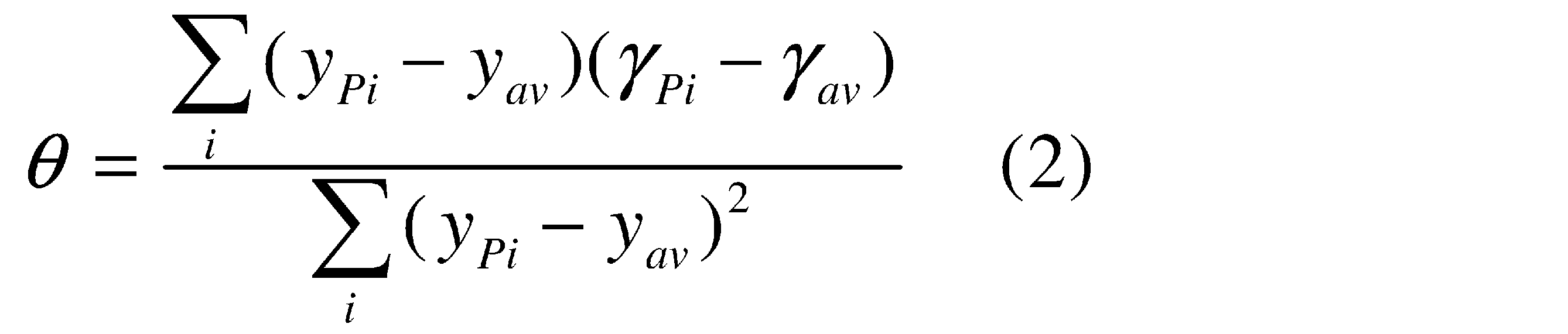 The regression coefficient calculation unit 72 calculates a regression coefficient based on the peak value and peak position calculated by the correlation
 search processing unit 71. The regression coefficient represents the slope of the regression line shown in FIG. Specifically, the regression coefficient calculation unit 72 calculates the regression coefficient θ based on the following equation (2).
ここで、γavは、正規化相関値γ(y,z)のピーク値γPiの平均値である。yavは、正規化相関値γ(y,z)のピーク位置yPiの平均値である。
Here, γ av is the average value of the peak values γ Pi of the normalized correlation values γ (y, z). y av is the average value of the peak positions y Pi of the normalized correlation values γ (y, z).
図9に示す例では、回帰係数θが負である。このように、回帰係数θが負であることは、軌道TRの下流側に撮像部62が合焦していること、すなわち、撮像部62の撮像位置が、プラズマ生成領域25から撮像部62側にずれていることを表す。逆に、回帰係数θが正であることは、撮像部62の撮像位置が、プラズマ生成領域25から撮像部62とは反対側にずれていることを表す。
In the example shown in FIG. 9, the regression coefficient θ is negative. Thus, the negative regression coefficient θ means that the imaging unit 62 is in focus on the downstream side of the trajectory TR, that is, the imaging position of the imaging unit 62 is from the plasma generation region 25 to the imaging unit 62 side. It represents that it is shifted to. Conversely, a positive regression coefficient θ indicates that the imaging position of the imaging unit 62 is shifted from the plasma generation region 25 to the side opposite to the imaging unit 62.
移動量算出部73は、回帰係数算出部72により算出された回帰係数θに基づき、撮像部62の撮像位置を、プラズマ生成領域25にほぼ一致させるために必要なセンサステージ62hの移動量を算出する。移動量には、移動方向、及び移動距離が含まれる。移動距離はスカラー量である。
Based on the regression coefficient θ calculated by the regression coefficient calculation unit 72, the movement amount calculation unit 73 calculates the movement amount of the sensor stage 62h necessary for making the imaging position of the imaging unit 62 substantially coincide with the plasma generation region 25. To do. The movement amount includes a movement direction and a movement distance. The moving distance is a scalar quantity.
具体的には、移動量算出部73は、回帰係数θの正負を判定し、回帰係数θが負である場合には、センサステージ62hの移動方向を「正方向」とし、回帰係数θが正である場合には、センサステージ62hの移動方向を「負方向」とする。正方向とは、撮像部62をプラズマ生成領域25に近づける方向である。負方向とは、撮像部62をプラズマ生成領域25から遠ざける方向である。
Specifically, the movement amount calculation unit 73 determines whether the regression coefficient θ is positive or negative. If the regression coefficient θ is negative, the movement direction of the sensor stage 62h is set to “positive direction”, and the regression coefficient θ is positive. In this case, the moving direction of the sensor stage 62h is set to the “negative direction”. The positive direction is a direction in which the imaging unit 62 is brought closer to the plasma generation region 25. The negative direction is a direction in which the imaging unit 62 is moved away from the plasma generation region 25.
また、移動量算出部73は、プラズマ生成領域25に対する撮像部62の撮像位置のずれ量と、回帰係数θの絶対値との関係とを予め記憶しており、回帰係数θの絶対値に基づいて、センサステージ62hの移動距離を算出する。
Further, the movement amount calculation unit 73 stores in advance a relationship between the amount of shift of the imaging position of the imaging unit 62 with respect to the plasma generation region 25 and the absolute value of the regression coefficient θ, and is based on the absolute value of the regression coefficient θ. Thus, the moving distance of the sensor stage 62h is calculated.
4.2 動作
EUV光生成装置1は、露光装置6から入力されるトリガ信号に応じて、EUV光を繰り返し出力するバースト期間と、EUV光を出力しない休止期間とを交互に繰り返すバースト動作を行う。バースト期間は、露光装置6において、半導体ウエハ上の1つの露光エリアに露光が行われる期間である。休止期間は、1つの露光エリアの露光が終了した後、別の露光エリアの露光が開始されるまでの期間である。休止期間には、図示しないウエハステージの移動が行われる。 4.2 Operation The EUVlight generation apparatus 1 performs a burst operation that alternately repeats a burst period in which EUV light is repeatedly output and a pause period in which EUV light is not output, in response to a trigger signal input from the exposure apparatus 6. . The burst period is a period during which exposure is performed on one exposure area on the semiconductor wafer in the exposure apparatus 6. The rest period is a period from the end of exposure of one exposure area to the start of exposure of another exposure area. During the pause period, the wafer stage (not shown) is moved.
EUV光生成装置1は、露光装置6から入力されるトリガ信号に応じて、EUV光を繰り返し出力するバースト期間と、EUV光を出力しない休止期間とを交互に繰り返すバースト動作を行う。バースト期間は、露光装置6において、半導体ウエハ上の1つの露光エリアに露光が行われる期間である。休止期間は、1つの露光エリアの露光が終了した後、別の露光エリアの露光が開始されるまでの期間である。休止期間には、図示しないウエハステージの移動が行われる。 4.2 Operation The EUV
バースト期間では、レーザ装置3によるレーザ発振動作と、ターゲット供給部26によるターゲット生成動作とが共に実行される。休止期間では、ターゲット生成動作が持続されたまま、レーザ発振動作が停止される。ターゲット画像計測装置60によるターゲット画像計測動作は、例えば、休止期間中に行われる。なお、ターゲット画像計測動作は、ターゲット生成動作が行われ、かつレーザ発振動作が停止されている期間に行われればよく、バースト動作の休止期間以外の期間に行われてもよい。
During the burst period, both the laser oscillation operation by the laser device 3 and the target generation operation by the target supply unit 26 are executed. In the pause period, the laser oscillation operation is stopped while the target generation operation is continued. The target image measurement operation by the target image measurement device 60 is performed, for example, during a pause period. The target image measurement operation may be performed in a period in which the target generation operation is performed and the laser oscillation operation is stopped, and may be performed in a period other than the pause period of the burst operation.
図14は、第1の実施形態におけるEUV光生成装置のターゲット画像計測動作を説明するフローチャートである。EUV光生成装置は、以下の処理により、ターゲット画像計測動作を行う。まず、S201において、照明部61によりパルス状の照明光が出力されるとともに、この照明光が照射された複数のターゲット27の像が、撮像部62により撮像される。この撮像により生成された画像データは、移動量決定部64に入力される。
FIG. 14 is a flowchart for explaining the target image measurement operation of the EUV light generation apparatus according to the first embodiment. The EUV light generation apparatus performs a target image measurement operation by the following processing. First, in S <b> 201, pulsed illumination light is output from the illumination unit 61, and images of a plurality of targets 27 irradiated with the illumination light are captured by the imaging unit 62. Image data generated by this imaging is input to the movement amount determination unit 64.
次に、S202おいて、相関サーチ処理部71により、テンプレート記憶部70に予め記憶されたターゲット27の合焦画像をテンプレートとして、正規化相関サーチ処理が行われる。また、相関サーチ処理部71により、撮像部62により撮像された各ターゲット27に対応する正規化相関値γ(y,z)のピーク値及びピーク位置が算出される。
Next, in S202, the correlation search processing unit 71 performs a normalized correlation search process using the focused image of the target 27 stored in advance in the template storage unit 70 as a template. Further, the correlation search processing unit 71 calculates the peak value and peak position of the normalized correlation value γ (y, z) corresponding to each target 27 imaged by the imaging unit 62.
次に、S203おいて、回帰係数算出部72により、回帰係数θが算出される。そして、S204おいて、EUV光生成制御部5により、回帰係数算出部72により算出された回帰係数θの絶対値が所定値以下であるか否かの判定が行われる。回帰係数θの絶対値が所定値より大きいと判定された場合(S204;No)には、S205に移行する。S205において、移動量算出部73により、回帰係数θに基づいて、センサステージ62hの移動量が算出される。
Next, in S203, the regression coefficient θ is calculated by the regression coefficient calculation unit 72. In step S204, the EUV light generation controller 5 determines whether or not the absolute value of the regression coefficient θ calculated by the regression coefficient calculator 72 is equal to or less than a predetermined value. When it is determined that the absolute value of the regression coefficient θ is larger than the predetermined value (S204; No), the process proceeds to S205. In S205, the movement amount calculation unit 73 calculates the movement amount of the sensor stage 62h based on the regression coefficient θ.
次に、S206において、EUV光生成制御部5は、移動量決定部64により決定された移動量に基づき、センサステージ62hに位置変更指令を出力し、センサステージ62hを移動させる。例えば、図9に示されるように、回帰係数θが負の場合には、センサステージ62hは、回帰係数θの絶対値に応じた距離だけ正方向に移動される。
Next, in S206, the EUV light generation control unit 5 outputs a position change command to the sensor stage 62h based on the movement amount determined by the movement amount determination unit 64, and moves the sensor stage 62h. For example, as shown in FIG. 9, when the regression coefficient θ is negative, the sensor stage 62h is moved in the positive direction by a distance corresponding to the absolute value of the regression coefficient θ.
図10は、センサステージ62hが移動することに伴い、撮像部62の撮像位置がプラズマ生成領域25にほぼ一致し、合焦状態となった例を示す。図11は、合焦状態において撮像部62により出力される画像データの例を示す。このように、プラズマ生成領域25に位置するターゲット27bの像はコントラストが向上し、鮮明化する。図12は、合焦状態における正規化相関値γ(y,z)の例を示す。図13に示すように、回帰直線の傾き、すなわち回帰係数θの値がほぼ「0」となる。
FIG. 10 shows an example in which the imaging position of the imaging unit 62 substantially coincides with the plasma generation region 25 and is brought into focus as the sensor stage 62h moves. FIG. 11 shows an example of image data output by the imaging unit 62 in the focused state. Thus, the contrast of the image of the target 27b located in the plasma generation region 25 is improved and sharpened. FIG. 12 shows an example of the normalized correlation value γ (y, z) in the focused state. As shown in FIG. 13, the slope of the regression line, that is, the value of the regression coefficient θ is almost “0”.
S206の後、再びS201に戻り、上述のS201~S204の動作が行われる。S204において、回帰係数θの絶対値が所定値以下であると判定された場合(S204;Yes)には、S207に移行する。S207では、上記比較例において説明した画像処理に代えて、濃淡ブロブ解析を行う。具体的には、画像処理部63は、S201において取得された画像データI(y,z)中から、正規化相関値γ(y,z)のピーク値が最も大きいターゲット27の像を対象として、濃淡ブロブ解析を行う。この濃淡ブロブ解析は、二値化処理を行わずに行われる。濃淡ブロブ解析の結果に基づいて、ターゲット27の状態を表すターゲット27の位置、形状、大きさ、軌道、速度等が求められる。
After S206, the process returns to S201 again, and the operations of S201 to S204 described above are performed. If it is determined in S204 that the absolute value of the regression coefficient θ is equal to or smaller than the predetermined value (S204; Yes), the process proceeds to S207. In S207, density blob analysis is performed instead of the image processing described in the comparative example. Specifically, the image processing unit 63 targets the image of the target 27 having the largest peak value of the normalized correlation value γ (y, z) from the image data I (y, z) acquired in S201. Then, the density blob analysis is performed. This density blob analysis is performed without performing binarization processing. Based on the result of the density blob analysis, the position, shape, size, trajectory, speed, and the like of the target 27 representing the state of the target 27 are obtained.
4.3 効果
第1の実施形態によれば、ターゲット27の軌道TRに対して傾斜した方向から撮像することにより得られた画像データに基づいて撮像部62の撮像位置を変更するので、ターゲット27を鮮明に撮像することができ、EUV光の生成を安定化させることができる。 4.3 Effect According to the first embodiment, the imaging position of theimaging unit 62 is changed based on the image data obtained by imaging from the direction inclined with respect to the trajectory TR of the target 27. Can be captured clearly, and the generation of EUV light can be stabilized.
第1の実施形態によれば、ターゲット27の軌道TRに対して傾斜した方向から撮像することにより得られた画像データに基づいて撮像部62の撮像位置を変更するので、ターゲット27を鮮明に撮像することができ、EUV光の生成を安定化させることができる。 4.3 Effect According to the first embodiment, the imaging position of the
5.第2の実施形態
次に、本開示の第2の実施形態に係るEUV光生成装置を含むEUV光生成システムについて説明する。なお、以下では、上記比較例、又は第1の実施形態に係るEUV光生成装置を含むEUV光生成システムの構成要素と略同じ部分については、同一の符号を付し、適宜説明を省略する。 5. Second Embodiment Next, an EUV light generation system including an EUV light generation apparatus according to a second embodiment of the present disclosure will be described. In the following description, substantially the same components as those of the comparative example or the EUV light generation system including the EUV light generation apparatus according to the first embodiment will be denoted by the same reference numerals, and description thereof will be omitted as appropriate.
次に、本開示の第2の実施形態に係るEUV光生成装置を含むEUV光生成システムについて説明する。なお、以下では、上記比較例、又は第1の実施形態に係るEUV光生成装置を含むEUV光生成システムの構成要素と略同じ部分については、同一の符号を付し、適宜説明を省略する。 5. Second Embodiment Next, an EUV light generation system including an EUV light generation apparatus according to a second embodiment of the present disclosure will be described. In the following description, substantially the same components as those of the comparative example or the EUV light generation system including the EUV light generation apparatus according to the first embodiment will be denoted by the same reference numerals, and description thereof will be omitted as appropriate.
第1の実施形態では、照明部61を撮像部62に対して対向させることにより、照明部61から出力された照明光を、ターゲット27の軌道TRを介して撮像部62に入射させている。すなわち、第1の実施形態では、照明光をターゲット27が遮蔽することにより生じる影を、ターゲット像として撮像している。これに対して、第2の実施形態では、照明部61を撮像部62に対して対向させないことにより、照明部61から出力された照明光を、ターゲット27の軌道TRに照射させる。すなわち、第2の実施形態では、ターゲット27による照明光の反射光を、ターゲット像として撮像する。
In the first embodiment, the illuminating unit 61 is opposed to the imaging unit 62 so that the illumination light output from the illuminating unit 61 is incident on the imaging unit 62 via the trajectory TR of the target 27. In other words, in the first embodiment, a shadow generated by the target 27 shielding the illumination light is captured as a target image. On the other hand, in 2nd Embodiment, the illumination part 61 is made not to oppose with respect to the imaging part 62, and the illumination light output from the illumination part 61 is irradiated to the track | orbit TR of the target 27. FIG. That is, in the second embodiment, the reflected light of the illumination light from the target 27 is captured as a target image.
図15は、本開示の第2の実施形態に係るEUV光生成装置に含まれるターゲット画像計測装置60、ターゲット供給部26、及びEUV光生成制御部5を示す。第2の実施形態に係るターゲット画像計測装置60は、主としてターゲット27の軌道TRを計測する、いわゆるフローセンサである。
FIG. 15 illustrates the target image measurement device 60, the target supply unit 26, and the EUV light generation control unit 5 included in the EUV light generation apparatus according to the second embodiment of the present disclosure. The target image measurement device 60 according to the second embodiment is a so-called flow sensor that mainly measures the trajectory TR of the target 27.
5.1 構成及び動作
5.1.1 撮像部及び照明部
撮像部62は、第1の実施形態と同様に、撮像方向がターゲット27の軌道TRに対して非直交でかつ非平行となるように配置されている。撮像部62の撮像方向と、Y方向とのなす角度φは、0<φ<90°または90°<φ<180°の角度範囲内に設定されている。第2の実施形態では、φ=45°としている。 5.1 Configuration and Operation 5.1.1 Imaging Unit and Illumination Unit Similar to the first embodiment, theimaging unit 62 is configured such that the imaging direction is non-orthogonal and non-parallel to the trajectory TR of the target 27. Is arranged. The angle φ formed by the imaging direction of the imaging unit 62 and the Y direction is set within an angle range of 0 <φ <90 ° or 90 ° <φ <180 °. In the second embodiment, φ = 45 °.
5.1.1 撮像部及び照明部
撮像部62は、第1の実施形態と同様に、撮像方向がターゲット27の軌道TRに対して非直交でかつ非平行となるように配置されている。撮像部62の撮像方向と、Y方向とのなす角度φは、0<φ<90°または90°<φ<180°の角度範囲内に設定されている。第2の実施形態では、φ=45°としている。 5.1 Configuration and Operation 5.1.1 Imaging Unit and Illumination Unit Similar to the first embodiment, the
照明部61は、撮像部62に対して対向しない位置に配置されている。第2の実施形態では、照明部61は、その照明方向が、撮像部62の撮像方向に直交するように配置されている。照明部61から出力される照射光は、プラズマ生成領域25及び合焦領域FAを含む領域を照射する。
The illumination unit 61 is disposed at a position that does not face the imaging unit 62. In the second embodiment, the illumination unit 61 is arranged such that the illumination direction is orthogonal to the imaging direction of the imaging unit 62. The irradiation light output from the illuminating unit 61 irradiates an area including the plasma generation area 25 and the focusing area FA.
第2の実施形態では、照明部61に含まれる光源61aは、パルス状の照明光ではなく、CW光を照明光として出力する。撮像部62に含まれるイメージセンサ62aは、ターゲット27により反射された光を受光する。EUV光生成制御部5は、光シャッタ62d及びイメージセンサ62aを制御し、ターゲット27の像が線状に撮像されるように露光時間を調整する。
In the second embodiment, the light source 61a included in the illumination unit 61 outputs CW light as illumination light instead of pulsed illumination light. The image sensor 62 a included in the imaging unit 62 receives the light reflected by the target 27. The EUV light generation controller 5 controls the optical shutter 62d and the image sensor 62a to adjust the exposure time so that the image of the target 27 is captured in a linear shape.
5.1.2 移動量決定部
図16は、第2の実施形態において撮像部62から出力される画像データI(y,z)の例を示す。第2の実施形態では、移動量決定部64に含まれる相関サーチ処理部71は、y方向に直交する複数のラインに沿って、1次元的に相関サーチ処理を行う。例えば、相関サーチ処理部71は、図16に示すように、y座標位置がyaである第1のラインLaと、y座標位置がybである第2のラインLbと、y座標位置がycである第3のラインLcとに沿って相関サーチ処理を行う。第2のラインLbは、プラズマ生成領域25に対応する画像データI(y,z)の中心を通過する。 5.1.2 Movement Amount Determination Unit FIG. 16 shows an example of image data I (y, z) output from theimaging unit 62 in the second embodiment. In the second embodiment, the correlation search processing unit 71 included in the movement amount determining unit 64 performs a one-dimensional correlation search process along a plurality of lines orthogonal to the y direction. For example, the correlation search processing unit 71, as shown in FIG. 16, a first line La y coordinate position is y a, and a second line Lb y coordinate position is y b, the y-coordinate position A correlation search process is performed along the third line Lc which is y c . The second line Lb passes through the center of the image data I (y, z) corresponding to the plasma generation region 25.
図16は、第2の実施形態において撮像部62から出力される画像データI(y,z)の例を示す。第2の実施形態では、移動量決定部64に含まれる相関サーチ処理部71は、y方向に直交する複数のラインに沿って、1次元的に相関サーチ処理を行う。例えば、相関サーチ処理部71は、図16に示すように、y座標位置がyaである第1のラインLaと、y座標位置がybである第2のラインLbと、y座標位置がycである第3のラインLcとに沿って相関サーチ処理を行う。第2のラインLbは、プラズマ生成領域25に対応する画像データI(y,z)の中心を通過する。 5.1.2 Movement Amount Determination Unit FIG. 16 shows an example of image data I (y, z) output from the
第2の実施形態では、相関サーチ処理部71による正規化相関サーチ処理は、例えば、下式(3)に基づいて行われる。
 In the second embodiment, the normalized correlation search process by the correlation
 search processing unit 71 is performed based on the following equation (3), for example.
図17は、第2の実施形態において、テンプレート記憶部70に記憶されるテンプレートデータT(z)の例を示す。このテンプレートデータT(z)は、線状のターゲット27の像のうち、合焦状態にある部分のz方向における輝度分布を表すものである。なお、zsは、テンプレートデータT(z)の中心位置を表している。相関サーチ処理部71は、テンプレートデータT(z)を用いて、中心位置zsを変更しながら正規化相関値γ(yi,zs)を算出する。yiは、相関サーチ処理を行うy座標位置を表している。以下、γ(yi,zs)を、単にγ(y,z)と表す。
FIG. 17 shows an example of template data T (z) stored in the template storage unit 70 in the second embodiment. This template data T (z) represents the luminance distribution in the z direction of the portion in the focused state in the image of the linear target 27. Note that z s represents the center position of the template data T (z). The correlation search processing unit 71 uses the template data T (z) to calculate a normalized correlation value γ (y i , z s ) while changing the center position z s . y i represents the y-coordinate position where the correlation search process is performed. Hereinafter, γ (y i , z s ) is simply expressed as γ (y, z).
図18は、第1~第3のラインLa~Lcに沿って得られる正規化相関値γ(y,z)の例を示す。第2の実施形態では、相関サーチ処理部71は、正規化相関値γ(y,z)に基づきピーク値及びピーク位置を求める。第1~第3のラインLa~Lcに沿って得られる正規化相関値γ(y,z)の各ピーク値は、図16に示す線状のターゲット27の像のうち、コントラストが高い部分を通るラインにおいて最も大きくなる。図19は、正規化相関値γ(y,z)の各ピーク値γPa,γPb,γPcを示している。
FIG. 18 shows an example of the normalized correlation value γ (y, z) obtained along the first to third lines La to Lc. In the second embodiment, the correlation search processing unit 71 obtains a peak value and a peak position based on the normalized correlation value γ (y, z). Each peak value of the normalized correlation value γ (y, z) obtained along the first to third lines La to Lc is a portion having a high contrast in the image of the linear target 27 shown in FIG. It becomes the largest in the line that passes. FIG. 19 shows peak values γ Pa , γ Pb , and γ Pc of the normalized correlation value γ (y, z).
回帰係数算出部72は、相関サーチ処理部71により算出されたピーク値及びピーク位置に基づいて回帰係数を算出する。具体的には、回帰係数算出部72は、下式(4)に基づいて回帰係数θを算出する。
 The regression coefficient calculation unit 72 calculates a regression coefficient based on the peak value and peak position calculated by the correlation
 search processing unit 71. Specifically, the regression coefficient calculation unit 72 calculates the regression coefficient θ based on the following equation (4).
ここで、γavは、正規化相関値γ(y,z)のピーク値γPiの平均値である。yavは、相関サーチ処理を行ったラインの座標位置yiの平均値、すなわちy方向に関するピーク位置の平均値である。
Here, γ av is the average value of the peak values γ Pi of the normalized correlation values γ (y, z). y av is the average value of the coordinate positions y i of the lines subjected to the correlation search process, that is, the average value of the peak positions in the y direction.
図19に示す例では、回帰係数θが負である。このように、回帰係数θが負であることは、軌道TRの下流側に撮像部62のフォーカスが合っていることを示している。第1の実施形態と同様に、移動量算出部73は、回帰係数算出部72により算出された回帰係数θに基づき、撮像部62の撮像位置を、プラズマ生成領域25にほぼ一致させるために必要なセンサステージ62hの移動量を算出する。
In the example shown in FIG. 19, the regression coefficient θ is negative. Thus, the negative regression coefficient θ indicates that the imaging unit 62 is in focus on the downstream side of the trajectory TR. Similar to the first embodiment, the movement amount calculation unit 73 is necessary to make the imaging position of the imaging unit 62 substantially coincide with the plasma generation region 25 based on the regression coefficient θ calculated by the regression coefficient calculation unit 72. The amount of movement of the correct sensor stage 62h is calculated.
その他の構成及び動作については、第1の実施形態と同様である。なお、第2の実施形態では、y座標位置が異なるz方向に沿った3本のラインに沿って正規化相関値γ(y,z)を算出する例を示しているが、このラインの数は、「3」に限られず、2以上であればよい。
Other configurations and operations are the same as those in the first embodiment. In the second embodiment, an example is shown in which the normalized correlation value γ (y, z) is calculated along three lines along the z direction at different y coordinate positions. Is not limited to “3” and may be two or more.
5.2 効果
第2の実施形態によれば、上述の相関サーチ処理を行うラインの数を多くすることにより、より精度よくセンサステージ62hの移動量を決定することができる。また、第2の実施形態では、各ラインにおいて求められる正規化相関値γ(y,z)のピーク位置から、ターゲット27の実際の軌道を精度よく求めることができる。 5.2 Effect According to the second embodiment, the amount of movement of thesensor stage 62h can be determined more accurately by increasing the number of lines on which the correlation search process is performed. In the second embodiment, the actual trajectory of the target 27 can be accurately obtained from the peak position of the normalized correlation value γ (y, z) obtained in each line.
第2の実施形態によれば、上述の相関サーチ処理を行うラインの数を多くすることにより、より精度よくセンサステージ62hの移動量を決定することができる。また、第2の実施形態では、各ラインにおいて求められる正規化相関値γ(y,z)のピーク位置から、ターゲット27の実際の軌道を精度よく求めることができる。 5.2 Effect According to the second embodiment, the amount of movement of the
6.第3の実施形態
次に、本開示の第3の実施形態に係るEUV光生成装置を含むEUV光生成システムについて説明する。なお、以下では、上記比較例、又は第1の実施形態に係るEUV光生成装置を含むEUV光生成システムの構成要素と略同じ部分については、同一の符号を付し、適宜説明を省略する。 6). Third Embodiment Next, an EUV light generation system including an EUV light generation apparatus according to a third embodiment of the present disclosure will be described. In the following description, substantially the same components as those of the comparative example or the EUV light generation system including the EUV light generation apparatus according to the first embodiment are denoted by the same reference numerals, and description thereof is omitted as appropriate.
次に、本開示の第3の実施形態に係るEUV光生成装置を含むEUV光生成システムについて説明する。なお、以下では、上記比較例、又は第1の実施形態に係るEUV光生成装置を含むEUV光生成システムの構成要素と略同じ部分については、同一の符号を付し、適宜説明を省略する。 6). Third Embodiment Next, an EUV light generation system including an EUV light generation apparatus according to a third embodiment of the present disclosure will be described. In the following description, substantially the same components as those of the comparative example or the EUV light generation system including the EUV light generation apparatus according to the first embodiment are denoted by the same reference numerals, and description thereof is omitted as appropriate.
第1の実施形態では、プラズマ生成領域25の位置は固定されているが、プラズマ生成領域25の位置は、露光装置6からの制御により変更されることがある。第3の実施形態として、プラズマ生成領域25の位置が変更される場合のEUV光生成システムについて説明する。
In the first embodiment, the position of the plasma generation region 25 is fixed, but the position of the plasma generation region 25 may be changed by control from the exposure apparatus 6. As a third embodiment, an EUV light generation system when the position of the plasma generation region 25 is changed will be described.
6.1 構成
6.1.1 制御系統
図20は、第3の実施形態において、プラズマ生成領域25が移動される場合におけるEUV光生成システムの制御系統を示す。第3の実施形態に係るEUV光生成装置に含まれるEUV光生成制御部5は、EUV光生成制御部5にとって外部装置である露光装置6から、プラズマ生成領域25を移動する指令信号を受信する。プラズマ生成領域25を移動する指令信号は、プラズマ生成領域25をX方向、Y方向、Z方向にそれぞれどれだけ移動させるか、またはプラズマ生成領域25をどの座標位置に移動させるかを示す情報を含んでいる。ここでは一例として、プラズマ生成領域25を座標位置(Xt,Yt,Zt)に移動させるものとする。 6.1 Configuration 6.1.1 Control System FIG. 20 shows a control system of the EUV light generation system when theplasma generation region 25 is moved in the third embodiment. The EUV light generation control unit 5 included in the EUV light generation apparatus according to the third embodiment receives a command signal for moving the plasma generation region 25 from the exposure apparatus 6 that is an external device for the EUV light generation control unit 5. . The command signal for moving the plasma generation region 25 includes information indicating how much the plasma generation region 25 is moved in each of the X direction, the Y direction, and the Z direction, or to which coordinate position the plasma generation region 25 is moved. It is out. Here, as an example, the plasma generation region 25 is moved to the coordinate position (Xt, Yt, Zt).
6.1.1 制御系統
図20は、第3の実施形態において、プラズマ生成領域25が移動される場合におけるEUV光生成システムの制御系統を示す。第3の実施形態に係るEUV光生成装置に含まれるEUV光生成制御部5は、EUV光生成制御部5にとって外部装置である露光装置6から、プラズマ生成領域25を移動する指令信号を受信する。プラズマ生成領域25を移動する指令信号は、プラズマ生成領域25をX方向、Y方向、Z方向にそれぞれどれだけ移動させるか、またはプラズマ生成領域25をどの座標位置に移動させるかを示す情報を含んでいる。ここでは一例として、プラズマ生成領域25を座標位置(Xt,Yt,Zt)に移動させるものとする。 6.1 Configuration 6.1.1 Control System FIG. 20 shows a control system of the EUV light generation system when the
EUV光生成制御部5は、露光装置6からプラズマ生成領域25を移動する指令信号を受信すると、以下のようにして、ターゲット位置とレーザ光集光位置とを変更することにより、プラズマ生成領域25を移動させる。
When the EUV light generation controller 5 receives a command signal for moving the plasma generation region 25 from the exposure apparatus 6, the EUV light generation control unit 5 changes the target position and the laser beam condensing position as follows, thereby changing the plasma generation region 25. Move.
EUV光生成制御部5は、所定タイミングにおけるターゲット27のY方向位置を座標位置Ytに変更するために、レーザ装置3を制御する。すなわち、EUV光生成制御部5は、レーザ装置3に発振タイミング変更指令を送信することにより、レーザ装置3がパルスレーザ光31を出力するための遅延時間を調整する。
The EUV light generation control unit 5 controls the laser device 3 in order to change the Y-direction position of the target 27 at a predetermined timing to the coordinate position Yt. That is, the EUV light generation controller 5 adjusts the delay time for the laser device 3 to output the pulsed laser light 31 by transmitting an oscillation timing change command to the laser device 3.
EUV光生成制御部5は、ターゲット27のX方向及びZ方向の位置を座標位置(Xt,Zt)に変更するために、ターゲット供給部アクチュエータ261を制御する。すなわち、EUV光生成制御部5は、ターゲット供給部アクチュエータ261にターゲット供給位置変更指令を送信することにより、ターゲット供給部26を移動させ、ターゲット27の軌道TRを移動させる。ターゲット供給部アクチュエータ261は、本開示のターゲット軌道変更部に相当する。
The EUV light generation control unit 5 controls the target supply unit actuator 261 in order to change the position of the target 27 in the X direction and the Z direction to the coordinate position (Xt, Zt). That is, the EUV light generation control unit 5 moves the target supply unit 26 to move the trajectory TR of the target 27 by transmitting a target supply position change command to the target supply unit actuator 261. The target supply unit actuator 261 corresponds to the target trajectory changing unit of the present disclosure.
EUV光生成制御部5は、レーザ光集光位置を座標位置(Xt,Yt,Zt)に変更するために、レーザ光伝送装置34を制御する。すなわち、EUV光生成制御部5は、レーザ光伝送装置34にレーザ光集光位置変更指令を送信することにより、レーザ光集光位置を変更させる。レーザ光伝送装置34は、本開示の集光位置変更部に相当する。
The EUV light generation controller 5 controls the laser light transmission device 34 in order to change the laser light condensing position to the coordinate position (Xt, Yt, Zt). That is, the EUV light generation control unit 5 changes the laser light condensing position by transmitting a laser light condensing position change command to the laser light transmission device 34. The laser beam transmission device 34 corresponds to the condensing position changing unit of the present disclosure.
また、EUV光生成制御部5は、プラズマ生成領域25を座標位置(Xt,Yt,Zt)に移動させることによる撮像部62の撮像方向に沿ったプラズマ生成領域25の移動量Ltを算出する。EUV光生成制御部5は、算出した移動量Ltを、センサステージ位置変更指令としてセンサステージ62hに送信することにより、撮像方向に沿ってセンサステージ62hの位置を変更させる。
Also, the EUV light generation control unit 5 calculates the movement amount Lt of the plasma generation region 25 along the imaging direction of the imaging unit 62 by moving the plasma generation region 25 to the coordinate position (Xt, Yt, Zt). The EUV light generation controller 5 changes the position of the sensor stage 62h along the imaging direction by transmitting the calculated movement amount Lt to the sensor stage 62h as a sensor stage position change command.
6.1.2 撮像部及び照明部
図21は、第3の実施形態に係るターゲット画像計測装置60の構成を示す。第3の実施形態における照明部61及び撮像部62の構成は、第1の実施形態と同様である。プラズマ生成領域25の位置は、上述のように露光装置6からの指令にしたがって、EUV光生成制御部5の制御により変更される。 6.1.2 Imaging Unit and Illumination Unit FIG. 21 shows a configuration of a targetimage measurement device 60 according to the third embodiment. The configurations of the illumination unit 61 and the imaging unit 62 in the third embodiment are the same as those in the first embodiment. The position of the plasma generation region 25 is changed by the control of the EUV light generation control unit 5 in accordance with the command from the exposure apparatus 6 as described above.
図21は、第3の実施形態に係るターゲット画像計測装置60の構成を示す。第3の実施形態における照明部61及び撮像部62の構成は、第1の実施形態と同様である。プラズマ生成領域25の位置は、上述のように露光装置6からの指令にしたがって、EUV光生成制御部5の制御により変更される。 6.1.2 Imaging Unit and Illumination Unit FIG. 21 shows a configuration of a target
図22は、移動前後のプラズマ生成領域25の座標位置を例示する。EUV光生成制御部5は、合焦領域FAの中心に位置するプラズマ生成領域25の初期の座標位置を(0,0,0)とし、移動後の座標位置を(Xt,Yt,Zt)とする。EUV光生成制御部5は、図22に示す幾何学的関係から導かれる下式(5)に基づいて、上述の移動量Ltを算出する。
 FIG. 22 illustrates the coordinate position of the
 plasma generation region 25 before and after movement. The EUV light generation controller 5 sets the initial coordinate position of the plasma generation area 25 located at the center of the focusing area FA as (0, 0, 0), and the coordinate position after the movement as (Xt, Yt, Zt). To do. The EUV light generation controller 5 calculates the above-described movement amount Lt based on the following equation (5) derived from the geometrical relationship shown in FIG.
EUV光生成制御部5は、算出した移動量Ltに基づき、撮像部62の合焦領域FA中に移動後の座標位置(Xt,Yt,Zt)が含まれるようにセンサステージ62hを移動させる。このように、プラズマ生成領域25の移動に応じて撮像位置を移動させることで、プラズマ生成領域25においてターゲット27の像を鮮明に撮像することができる。しかし、プラズマ生成領域25の移動に応じて撮像位置を移動させたとしても、その後に撮像位置の変動が生じ得る。この撮像位置の変動は、第1の実施形態と同様に、例えば、EUV光やパルスレーザ光33の散乱光による加熱によって、ウインドウ62gや結像光学系62c等の光学素子の屈折率が変動することに起因する。
The EUV light generation control unit 5 moves the sensor stage 62h based on the calculated movement amount Lt so that the coordinate position (Xt, Yt, Zt) after movement is included in the in-focus area FA of the imaging unit 62. As described above, by moving the imaging position according to the movement of the plasma generation region 25, it is possible to clearly capture the image of the target 27 in the plasma generation region 25. However, even if the imaging position is moved in accordance with the movement of the plasma generation region 25, the imaging position may vary thereafter. As in the first embodiment, the change in the imaging position is caused by the refractive index of an optical element such as the window 62g or the imaging optical system 62c being changed by heating with scattered light of EUV light or pulsed laser light 33, for example. Due to that.
このため、第3の実施形態においても、ターゲット27の軌道TRに対して傾斜した方向から撮像することにより得られた画像データに基づいて、撮像部62の撮像位置の変更が行われる。
For this reason, also in the third embodiment, the imaging position of the imaging unit 62 is changed based on image data obtained by imaging from a direction inclined with respect to the trajectory TR of the target 27.
6.1.3 移動量決定部
図23は、第3の実施形態に係る画像処理部63に含まれる移動量決定部64aの構成を示す。第3の実施形態の移動量決定部64aは、第1の実施形態の移動量決定部64に含まれる回帰係数算出部72に代えて、変位量算出部74を含んでいる。すなわち、第3の実施形態の移動量決定部64aは、テンプレート記憶部70と、相関サーチ処理部71と、変位量算出部74と、移動量算出部73と、を含んでいる。 6.1.3 Movement Amount Determination Unit FIG. 23 shows a configuration of a movementamount determination unit 64a included in the image processing unit 63 according to the third embodiment. The movement amount determination unit 64a of the third embodiment includes a displacement amount calculation unit 74 instead of the regression coefficient calculation unit 72 included in the movement amount determination unit 64 of the first embodiment. That is, the movement amount determination unit 64a of the third embodiment includes a template storage unit 70, a correlation search processing unit 71, a displacement amount calculation unit 74, and a movement amount calculation unit 73.
図23は、第3の実施形態に係る画像処理部63に含まれる移動量決定部64aの構成を示す。第3の実施形態の移動量決定部64aは、第1の実施形態の移動量決定部64に含まれる回帰係数算出部72に代えて、変位量算出部74を含んでいる。すなわち、第3の実施形態の移動量決定部64aは、テンプレート記憶部70と、相関サーチ処理部71と、変位量算出部74と、移動量算出部73と、を含んでいる。 6.1.3 Movement Amount Determination Unit FIG. 23 shows a configuration of a movement
第1の実施形態と同様に、相関サーチ処理部71は、テンプレート記憶部70に記憶された合焦画像をテンプレートとして、上述の式(1)に基づいて、正規化相関サーチ処理を行う。なお、第3の実施形態では、画像データI(y,z)には、5個程度のターゲット27の像が撮像されていることが好ましい。
As in the first embodiment, the correlation search processing unit 71 performs a normalized correlation search process based on the above-described equation (1) using the focused image stored in the template storage unit 70 as a template. In the third embodiment, it is preferable that about five images of the target 27 are captured in the image data I (y, z).
図24は、相関サーチ処理部71により各ターゲット27の像について算出される正規化相関値γ(y,z)のピーク値を例示している。変位量算出部74は、正規化相関値γ(y,z)の最大相関位置yPmを求め、この最大相関位置yPmのプラズマ生成領域25に対応する位置ytからの変位量ΔyPmを算出する。最大相関位置yPmは、正規化相関値γ(y,z)の最大値γPmに対するy座標位置である。
FIG. 24 illustrates the peak value of the normalized correlation value γ (y, z) calculated for the image of each target 27 by the correlation search processing unit 71. Displacement amount calculation unit 74, the normalized correlation value gamma (y, z) determine the maximum correlation position y Pm of the displacement amount [Delta] y Pm from the position y t corresponding to the plasma generation region 25 of the maximum correlation position y Pm calculate. The maximum correlation position y Pm is the y coordinate position with respect to the maximum value γ Pm of the normalized correlation value γ (y, z).
具体的には、変位量算出部74は、プラズマ生成領域25に対応する位置ytを、下式(6)に基づいて算出する。位置ytは、画像データI(y,z)上におけるプラズマ生成領域25のy座標位置である。
 Specifically, the displacement amount calculation unit 74, the position y t corresponding to the
 plasma generation region 25, is calculated based on the following equation (6). Position y t is the y-coordinate position of the plasma generation region 25 on the image data I (y, z).
また、変位量算出部74は、変位量ΔyPmを、下式(7)に基づいて算出する。
 Further, the displacement amount calculation unit 74 calculates the displacement amount Δy Pm based on the following equation (7).
第3の実施形態では、移動量算出部73は、変位量算出部74により算出された変位量ΔyPmに基づき、撮像部62の撮像位置を、プラズマ生成領域25にほぼ一致させるために必要なセンサステージ62hの移動量を算出する。
In the third embodiment, the movement amount calculation unit 73 is necessary to make the imaging position of the imaging unit 62 substantially coincide with the plasma generation region 25 based on the displacement amount Δy Pm calculated by the displacement amount calculation unit 74. The amount of movement of the sensor stage 62h is calculated.
具体的には、移動量算出部73は、変位量ΔyPmの正負を判定し、変位量ΔyPmが正である場合には、センサステージ62hの移動方向を「正方向」とし、変位量ΔyPmが負である場合には、センサステージ62hの移動方向を「負方向」とする。正方向とは、撮像部62をプラズマ生成領域25に近づける方向である。負方向とは、撮像部62をプラズマ生成領域25から遠ざける方向である。
Specifically, the shift amount calculating part 73 determines the sign of the displacement amount [Delta] y Pm, if the amount of displacement [Delta] y Pm is positive, the movement direction of the sensor stage 62h is "positive", the displacement amount [Delta] y When Pm is negative, the moving direction of the sensor stage 62h is set to the “negative direction”. The positive direction is a direction in which the imaging unit 62 is brought closer to the plasma generation region 25. The negative direction is a direction in which the imaging unit 62 is moved away from the plasma generation region 25.
また、移動量算出部73は、プラズマ生成領域25に対する撮像部62の撮像位置のずれ量と、変位量ΔyPmの絶対値との関係とを予め記憶しており、変位量ΔyPmの絶対値に基づいて、センサステージ62hの移動距離を算出する。
Further, the shift amount calculating part 73, a shift amount of the imaging position of the imaging unit 62 to the plasma generation region 25 stores in advance the relationship between the absolute value of the displacement amount [Delta] y Pm, the absolute value of the displacement amount [Delta] y Pm Based on the above, the moving distance of the sensor stage 62h is calculated.
6.2 動作
図25は、第3の実施形態におけるEUV光生成装置のターゲット画像計測動作を説明するフローチャートである。EUV光生成装置は、以下の処理により、ターゲット画像計測動作を行う。まず、S301において、EUV光生成制御部5は、露光装置6から送出されるプラズマ生成領域25の移動指令信号を待ち受ける。次に、S302において、EUV光生成制御部5は、露光装置6からプラズマ生成領域25の移動指令信号を受信すると(S301;Yes)、移動指令信号に従ってプラズマ生成領域25を移動させ、撮像方向に沿ったプラズマ生成領域25の移動量Ltを算出する。プラズマ生成領域25の移動は、EUV光生成制御部5が、レーザ装置3、ターゲット供給部アクチュエータ261、及びレーザ光伝送装置34を制御することにより行われる。 6.2 Operation FIG. 25 is a flowchart for explaining the target image measurement operation of the EUV light generation apparatus according to the third embodiment. The EUV light generation apparatus performs a target image measurement operation by the following processing. First, in step S <b> 301, the EUV lightgeneration control unit 5 waits for a movement command signal for the plasma generation region 25 sent from the exposure apparatus 6. Next, in S302, when the EUV light generation control unit 5 receives a movement command signal for the plasma generation region 25 from the exposure apparatus 6 (S301; Yes), the EUV light generation control unit 5 moves the plasma generation region 25 according to the movement command signal and moves it in the imaging direction. The amount of movement Lt of the plasma generation region 25 along is calculated. The movement of the plasma generation region 25 is performed by the EUV light generation control unit 5 controlling the laser device 3, the target supply unit actuator 261, and the laser light transmission device 34.
図25は、第3の実施形態におけるEUV光生成装置のターゲット画像計測動作を説明するフローチャートである。EUV光生成装置は、以下の処理により、ターゲット画像計測動作を行う。まず、S301において、EUV光生成制御部5は、露光装置6から送出されるプラズマ生成領域25の移動指令信号を待ち受ける。次に、S302において、EUV光生成制御部5は、露光装置6からプラズマ生成領域25の移動指令信号を受信すると(S301;Yes)、移動指令信号に従ってプラズマ生成領域25を移動させ、撮像方向に沿ったプラズマ生成領域25の移動量Ltを算出する。プラズマ生成領域25の移動は、EUV光生成制御部5が、レーザ装置3、ターゲット供給部アクチュエータ261、及びレーザ光伝送装置34を制御することにより行われる。 6.2 Operation FIG. 25 is a flowchart for explaining the target image measurement operation of the EUV light generation apparatus according to the third embodiment. The EUV light generation apparatus performs a target image measurement operation by the following processing. First, in step S <b> 301, the EUV light
次に、S303において、EUV光生成制御部5は、算出した移動量Ltに基づき、センサステージ62hに位置変更指令信号を送出する。センサステージ62hは、位置変更指令信号を受け、移動後のプラズマ生成領域25が合焦領域FA中に含まれる位置に移動される。以上のようにプラズマ生成領域25の移動に応じてセンサステージ62hを移動させたとしても、光学素子の屈折率変動等によって撮像部62の撮像位置が変動し、プラズマ生成領域25が合焦領域FA外となることがある。
Next, in S303, the EUV light generation controller 5 sends a position change command signal to the sensor stage 62h based on the calculated movement amount Lt. The sensor stage 62h receives the position change command signal, and is moved to a position where the moved plasma generation area 25 is included in the focusing area FA. As described above, even if the sensor stage 62h is moved in accordance with the movement of the plasma generation region 25, the imaging position of the imaging unit 62 varies due to a change in the refractive index of the optical element or the like, and the plasma generation region 25 becomes in the focus region FA May be outside.
続く、S304は、例えば、バースト動作の休止期間に行われる。まず、S304において、照明部61によりパルス状の照明光が出力されるとともに、この照明光が照射された複数のターゲット27の像が、撮像部62により撮像される。この撮像により生成された画像データは、移動量決定部64aに入力される。
Subsequently, S304 is performed, for example, during a pause period of the burst operation. First, in S <b> 304, pulsed illumination light is output from the illumination unit 61, and images of the plurality of targets 27 irradiated with the illumination light are captured by the imaging unit 62. Image data generated by this imaging is input to the movement amount determination unit 64a.
次に、S305おいて、相関サーチ処理部71により、テンプレート記憶部70に予め記憶されたターゲット27の合焦画像をテンプレートとして、正規化相関サーチ処理が行われる。また、相関サーチ処理部71により、撮像部62により撮像された各ターゲット27に対応する正規化相関値γ(y,z)のピーク値及びピーク位置が算出される。
Next, in S305, the correlation search processing unit 71 performs a normalized correlation search process using the focused image of the target 27 stored in advance in the template storage unit 70 as a template. Further, the correlation search processing unit 71 calculates the peak value and peak position of the normalized correlation value γ (y, z) corresponding to each target 27 imaged by the imaging unit 62.
次に、S306おいて、変位量算出部74により、正規化相関値γ(y,z)の最大相関位置yPmと、画像データI(y,z)上のプラズマ生成領域25に対応する位置ytとが求められ、変位量ΔyPmが算出される。そして、S307おいて、EUV光生成制御部5により、変位量算出部74により算出された変位量ΔyPmの絶対値が所定値以下であるか否かの判定が行われる。変位量ΔyPmの絶対値が所定値より大きいと判定された場合(S307;No)には、S308に移行する。S308において、移動量算出部73により、変位量ΔyPmに基づいて、センサステージ62hの移動量が算出される。
Next, in S306, the displacement amount calculation unit 74 causes the maximum correlation position y Pm of the normalized correlation value γ (y, z) and the position corresponding to the plasma generation region 25 on the image data I (y, z). y t is obtained, and the displacement amount Δy Pm is calculated. In step S307, the EUV light generation controller 5 determines whether or not the absolute value of the displacement amount Δy Pm calculated by the displacement amount calculator 74 is equal to or less than a predetermined value. When it is determined that the absolute value of the displacement amount Δy Pm is larger than the predetermined value (S307; No), the process proceeds to S308. In S308, the movement amount calculation unit 73 calculates the movement amount of the sensor stage 62h based on the displacement amount Δy Pm .
次に、S309において、EUV光生成制御部5は、移動量決定部64aにより決定された移動量に基づき、センサステージ62hに位置変更指令を出力し、センサステージ62hを移動させる。例えば、図28に示されるように、変位量ΔyPmが正の場合には、センサステージ62hは、変位量ΔyPmの絶対値に応じた距離だけ正方向に移動される。
Next, in S309, the EUV light generation control unit 5 outputs a position change command to the sensor stage 62h based on the movement amount determined by the movement amount determination unit 64a, and moves the sensor stage 62h. For example, as shown in FIG. 28, when the displacement amount Δy Pm is positive, the sensor stage 62h is moved in the positive direction by a distance corresponding to the absolute value of the displacement amount Δy Pm .
この後、再びS304に戻り、上述のS204~S307の動作が行われる。S307において、変位量ΔyPmの絶対値が所定値以下であると判定された場合(S307;Yes)には、S310に移行する。S310では、第1の実施形態と同様の画像処理が行われる。
Thereafter, the process returns to S304 again, and the operations of S204 to S307 described above are performed. In S307, when it is determined that the absolute value of the displacement amount Δy Pm is equal to or less than the predetermined value (S307; Yes), the process proceeds to S310. In S310, image processing similar to that in the first embodiment is performed.
6.3 効果
第3の実施形態によれば、プラズマ生成領域25が移動された場合においても、ターゲット27を鮮明に撮像することができ、EUV光の生成を安定化させることができる。 6.3 Effect According to the third embodiment, even when theplasma generation region 25 is moved, the target 27 can be clearly imaged, and the generation of EUV light can be stabilized.
第3の実施形態によれば、プラズマ生成領域25が移動された場合においても、ターゲット27を鮮明に撮像することができ、EUV光の生成を安定化させることができる。 6.3 Effect According to the third embodiment, even when the
7.第4の実施形態
次に、本開示の第4の実施形態に係るEUV光生成装置を含むEUV光生成システムについて説明する。なお、以下では、上記比較例、又は第2の実施形態に係るEUV光生成装置を含むEUV光生成システムの構成要素と略同じ部分については、同一の符号を付し、適宜説明を省略する。 7). Fourth Embodiment Next, an EUV light generation system including an EUV light generation apparatus according to a fourth embodiment of the present disclosure will be described. In the following description, substantially the same components as those of the comparative example or the EUV light generation system including the EUV light generation apparatus according to the second embodiment will be denoted by the same reference numerals, and description thereof will be omitted as appropriate.
次に、本開示の第4の実施形態に係るEUV光生成装置を含むEUV光生成システムについて説明する。なお、以下では、上記比較例、又は第2の実施形態に係るEUV光生成装置を含むEUV光生成システムの構成要素と略同じ部分については、同一の符号を付し、適宜説明を省略する。 7). Fourth Embodiment Next, an EUV light generation system including an EUV light generation apparatus according to a fourth embodiment of the present disclosure will be described. In the following description, substantially the same components as those of the comparative example or the EUV light generation system including the EUV light generation apparatus according to the second embodiment will be denoted by the same reference numerals, and description thereof will be omitted as appropriate.
第2の実施形態では、プラズマ生成領域25の位置は固定されているが、プラズマ生成領域25の位置は、露光装置6からの制御により変更されることがある。第4の実施形態として、プラズマ生成領域25の位置が変更される場合のEUV光生成システムについて説明する。
In the second embodiment, the position of the plasma generation region 25 is fixed, but the position of the plasma generation region 25 may be changed by control from the exposure apparatus 6. As a fourth embodiment, an EUV light generation system when the position of the plasma generation region 25 is changed will be described.
7.1 構成及び動作
7.1.1 制御系統
第4の実施形態に係るEUV光生成装置の制御系統は、図20に示される第3の実施形態の制御系統と同様である。EUV光生成制御部5は、露光装置6からプラズマ生成領域25を移動する指令信号を受信すると、以下のようにして、ターゲット位置とレーザ光集光位置とを変更することにより、プラズマ生成領域25を移動させる。 7.1 Configuration and Operation 7.1.1 Control System The control system of the EUV light generation apparatus according to the fourth embodiment is the same as the control system of the third embodiment shown in FIG. When the EUVlight generation controller 5 receives a command signal for moving the plasma generation region 25 from the exposure apparatus 6, the EUV light generation control unit 5 changes the target position and the laser beam condensing position as follows, thereby changing the plasma generation region 25. Move.
7.1.1 制御系統
第4の実施形態に係るEUV光生成装置の制御系統は、図20に示される第3の実施形態の制御系統と同様である。EUV光生成制御部5は、露光装置6からプラズマ生成領域25を移動する指令信号を受信すると、以下のようにして、ターゲット位置とレーザ光集光位置とを変更することにより、プラズマ生成領域25を移動させる。 7.1 Configuration and Operation 7.1.1 Control System The control system of the EUV light generation apparatus according to the fourth embodiment is the same as the control system of the third embodiment shown in FIG. When the EUV
また、EUV光生成制御部5は、プラズマ生成領域25を座標位置(Xt,Yt,Zt)に移動させることによる撮像部62の撮像方向に沿ったプラズマ生成領域25の移動量Ltを算出する。EUV光生成制御部5は、算出した移動量Ltを、センサステージ位置変更指令としてセンサステージ62hに送信することにより、撮像方向に沿ってセンサステージ62hの位置を変更させる。
Also, the EUV light generation control unit 5 calculates the movement amount Lt of the plasma generation region 25 along the imaging direction of the imaging unit 62 by moving the plasma generation region 25 to the coordinate position (Xt, Yt, Zt). The EUV light generation controller 5 changes the position of the sensor stage 62h along the imaging direction by transmitting the calculated movement amount Lt to the sensor stage 62h as a sensor stage position change command.
7.1.2 撮像部及び照明部
図26は、第4の実施形態に係るターゲット画像計測装置60の構成を示す。第4の実施形態における照明部61及び撮像部62の構成は、第2の実施形態と同様である。プラズマ生成領域25の位置は、上述のように露光装置6からの指令にしたがって、EUV光生成制御部5の制御により変更される。EUV光生成制御部5は、第3の実施形態と同様に移動量Ltを算出し、算出した移動量Ltに基づき、撮像部62の合焦領域FA中に移動後の座標位置(Xt,Yt,Zt)が含まれるようにセンサステージ62hを移動させる。 7.1.2 Imaging Unit and Illumination Unit FIG. 26 shows a configuration of a targetimage measurement device 60 according to the fourth embodiment. The configurations of the illumination unit 61 and the imaging unit 62 in the fourth embodiment are the same as those in the second embodiment. The position of the plasma generation region 25 is changed by the control of the EUV light generation control unit 5 in accordance with the command from the exposure apparatus 6 as described above. The EUV light generation controller 5 calculates the movement amount Lt as in the third embodiment, and based on the calculated movement amount Lt, the coordinate position (Xt, Yt after movement) in the in-focus area FA of the imaging unit 62. , Zt), the sensor stage 62h is moved.
図26は、第4の実施形態に係るターゲット画像計測装置60の構成を示す。第4の実施形態における照明部61及び撮像部62の構成は、第2の実施形態と同様である。プラズマ生成領域25の位置は、上述のように露光装置6からの指令にしたがって、EUV光生成制御部5の制御により変更される。EUV光生成制御部5は、第3の実施形態と同様に移動量Ltを算出し、算出した移動量Ltに基づき、撮像部62の合焦領域FA中に移動後の座標位置(Xt,Yt,Zt)が含まれるようにセンサステージ62hを移動させる。 7.1.2 Imaging Unit and Illumination Unit FIG. 26 shows a configuration of a target
7.1.3 移動量決定部
第4の実施形態に係る画像処理部63に含まれる移動量決定部64aの構成は、図23に示される第3の実施形態の移動量決定部64aの構成と同様である。但し、相関サーチ処理部71は、第2の実施形態と同様に、上述の式(3)に基づく相関サーチ処理を行う。第4の実施形態では、相関サーチを行うラインの数は、5程度であることが好ましい。 7.1.3 Movement Amount Determination Unit The configuration of the movementamount determination unit 64a included in the image processing unit 63 according to the fourth embodiment is the configuration of the movement amount determination unit 64a of the third embodiment shown in FIG. It is the same. However, the correlation search processing unit 71 performs the correlation search processing based on the above-described formula (3), as in the second embodiment. In the fourth embodiment, the number of lines on which a correlation search is performed is preferably about 5.
第4の実施形態に係る画像処理部63に含まれる移動量決定部64aの構成は、図23に示される第3の実施形態の移動量決定部64aの構成と同様である。但し、相関サーチ処理部71は、第2の実施形態と同様に、上述の式(3)に基づく相関サーチ処理を行う。第4の実施形態では、相関サーチを行うラインの数は、5程度であることが好ましい。 7.1.3 Movement Amount Determination Unit The configuration of the movement
変位量算出部74は、上式(3)に基づいて算出された正規化相関値γ(y,z)の最大相関位置yPmを求め、この最大相関位置yPmのプラズマ生成領域25に対応する位置ytからの変位量ΔyPmを算出する。位置ytは、上述の式(6)に基づいて算出される。また、変位量算出部74は、変位量ΔyPmを、上述の式(7)に基づいて算出する。
The displacement amount calculation unit 74 obtains the maximum correlation position y Pm of the normalized correlation value γ (y, z) calculated based on the above equation (3), and corresponds to the plasma generation region 25 of the maximum correlation position y Pm. It calculates the displacement amount [Delta] y Pm from the position y t be. Position y t is calculated based on equation (6) described above. Further, the displacement amount calculation unit 74 calculates the displacement amount Δy Pm based on the above equation (7).
移動量算出部73は、変位量算出部74により算出された変位量ΔyPmに基づき、撮像部62の撮像位置を、プラズマ生成領域25にほぼ一致させるために必要なセンサステージ62hの移動量を算出する。
Based on the displacement amount Δy Pm calculated by the displacement amount calculation unit 74, the movement amount calculation unit 73 calculates a movement amount of the sensor stage 62 h necessary for making the imaging position of the imaging unit 62 substantially coincide with the plasma generation region 25. calculate.
第4の実施形態におけるEUV光生成装置のその他の構成及び動作は、第3の実施形態におけるEUV光生成装置の構成及び動作と同様である。
Other configurations and operations of the EUV light generation apparatus according to the fourth embodiment are the same as those of the EUV light generation apparatus according to the third embodiment.
8.変形例
8.1 撮像部の撮像方向
第1~第4の実施形態では、撮像部62の撮像方向を、ターゲット27の軌道TRに対して非直交でかつ非平行であって、XY平面と平行としているが、これに限られず、XY平面と非平行であってもよい。例えば、撮像部62の撮像方向を、ターゲット27の軌道TRに対して非直交でかつ非平行であって、YZ平面と平行としてもよい。 8). Modification 8.1 Imaging Direction of Imaging Unit In the first to fourth embodiments, the imaging direction of theimaging unit 62 is non-orthogonal and non-parallel to the trajectory TR of the target 27 and parallel to the XY plane. However, the present invention is not limited to this, and may be non-parallel to the XY plane. For example, the imaging direction of the imaging unit 62 may be non-orthogonal and non-parallel to the trajectory TR of the target 27 and parallel to the YZ plane.
8.1 撮像部の撮像方向
第1~第4の実施形態では、撮像部62の撮像方向を、ターゲット27の軌道TRに対して非直交でかつ非平行であって、XY平面と平行としているが、これに限られず、XY平面と非平行であってもよい。例えば、撮像部62の撮像方向を、ターゲット27の軌道TRに対して非直交でかつ非平行であって、YZ平面と平行としてもよい。 8). Modification 8.1 Imaging Direction of Imaging Unit In the first to fourth embodiments, the imaging direction of the
8.2 撮像部及び照明部
第1~第4の実施形態では、照明部61と撮像部62とを1セットのみ設けているが、照明部61と撮像部62とを複数セット設けてもよい。この場合、各撮像部62の撮像方向を、互いにそれぞれ異なる方向とすることが好ましい。これにより、ターゲット27の画像計測を複数の方向から行うことが可能となる。 8.2 Imaging Unit and Illumination Unit In the first to fourth embodiments, only one set of theillumination unit 61 and the imaging unit 62 is provided, but a plurality of sets of the illumination unit 61 and the imaging unit 62 may be provided. . In this case, it is preferable that the imaging directions of the imaging units 62 are different from each other. Thereby, the image measurement of the target 27 can be performed from a plurality of directions.
第1~第4の実施形態では、照明部61と撮像部62とを1セットのみ設けているが、照明部61と撮像部62とを複数セット設けてもよい。この場合、各撮像部62の撮像方向を、互いにそれぞれ異なる方向とすることが好ましい。これにより、ターゲット27の画像計測を複数の方向から行うことが可能となる。 8.2 Imaging Unit and Illumination Unit In the first to fourth embodiments, only one set of the
8.3 撮像部の撮像位置の変更
第1~第4の実施形態では、撮像部62の筐体62fを保持したセンサステージ62hを撮像方向に沿って移動させることにより、撮像部62の撮像位置を変更しているが、これに限られず、その他の機構により撮像部62の撮像位置を変更してもよい。例えば、筐体62f内の一部の光学素子のみを撮像方向に沿って移動させることにより、撮像部62の撮像位置を変更してもよい。このように、撮像部62の全体を移動させずに、一部の光学素子を移動させる場合には、移動対象の光学素子の移動量に対する撮像位置の移動量の倍率を考慮する必要がある。 8.3 Changing the Imaging Position of the Imaging Unit In the first to fourth embodiments, the imaging position of theimaging unit 62 is moved by moving the sensor stage 62h holding the housing 62f of the imaging unit 62 along the imaging direction. However, the present invention is not limited to this, and the imaging position of the imaging unit 62 may be changed by other mechanisms. For example, the imaging position of the imaging unit 62 may be changed by moving only some of the optical elements in the housing 62f along the imaging direction. As described above, when moving some of the optical elements without moving the entire imaging unit 62, it is necessary to consider the magnification of the moving amount of the imaging position with respect to the moving amount of the optical element to be moved.
第1~第4の実施形態では、撮像部62の筐体62fを保持したセンサステージ62hを撮像方向に沿って移動させることにより、撮像部62の撮像位置を変更しているが、これに限られず、その他の機構により撮像部62の撮像位置を変更してもよい。例えば、筐体62f内の一部の光学素子のみを撮像方向に沿って移動させることにより、撮像部62の撮像位置を変更してもよい。このように、撮像部62の全体を移動させずに、一部の光学素子を移動させる場合には、移動対象の光学素子の移動量に対する撮像位置の移動量の倍率を考慮する必要がある。 8.3 Changing the Imaging Position of the Imaging Unit In the first to fourth embodiments, the imaging position of the
また、第1~第4の実施形態では、直動アクチュエータであるセンサステージ62hにより撮像部62を移動させているが、撮像部62を移動させるためのアクチュエータはこれに限られず、他のアクチュエータを用いてもよい。
In the first to fourth embodiments, the imaging unit 62 is moved by the sensor stage 62h, which is a linear motion actuator, but the actuator for moving the imaging unit 62 is not limited to this, and other actuators may be used. It may be used.
8.4 制御部
第1~第4の実施形態におけるEUV光生成制御部5、信号処理部53、及び画像処理部63は、コンピュータやプログラマブルコントローラ等の汎用の制御機器によって構成されてもよい。また、テンプレート記憶部70と、相関サーチ処理部71と、回帰係数算出部72と、移動量算出部73と、変位量算出部74とは、FPGAやカスタムチップ等によって構成されてもよい。或いは、不図示のROMやハードディスク等の記憶媒体に記憶され、実行時に随時読み出し可能なソフトウェアによって実現されてもよい。 8.4 Control Unit The EUV lightgeneration control unit 5, the signal processing unit 53, and the image processing unit 63 in the first to fourth embodiments may be configured by a general-purpose control device such as a computer or a programmable controller. The template storage unit 70, the correlation search processing unit 71, the regression coefficient calculation unit 72, the movement amount calculation unit 73, and the displacement amount calculation unit 74 may be configured by an FPGA, a custom chip, or the like. Alternatively, it may be realized by software that is stored in a storage medium such as a ROM or a hard disk (not shown) and can be read at any time during execution.
第1~第4の実施形態におけるEUV光生成制御部5、信号処理部53、及び画像処理部63は、コンピュータやプログラマブルコントローラ等の汎用の制御機器によって構成されてもよい。また、テンプレート記憶部70と、相関サーチ処理部71と、回帰係数算出部72と、移動量算出部73と、変位量算出部74とは、FPGAやカスタムチップ等によって構成されてもよい。或いは、不図示のROMやハードディスク等の記憶媒体に記憶され、実行時に随時読み出し可能なソフトウェアによって実現されてもよい。 8.4 Control Unit The EUV light
上記の説明は、制限ではなく単なる例示を意図したものである。従って、添付の特許請求の範囲を逸脱することなく本開示の各実施形態に変更を加えることができることは、当業者には明らかであろう。
The above description is intended to be illustrative only and not limiting. Thus, it will be apparent to one skilled in the art that modifications may be made to the embodiments of the present disclosure without departing from the scope of the appended claims.
本明細書及び添付の特許請求の範囲全体で使用される用語は、「限定的でない」用語と解釈されるべきである。例えば、「含む」又は「含まれる」という用語は、「含まれるものとして記載されたものに限定されない」と解釈されるべきである。「有する」という用語は、「有するものとして記載されたものに限定されない」と解釈されるべきである。また、本明細書及び添付の特許請求の範囲に記載される修飾句「1つの」は、「少なくとも1つ」又は「1又はそれ以上」を意味すると解釈されるべきである。
Terms used throughout this specification and the appended claims should be construed as "non-limiting" terms. For example, the terms “include” or “included” should be interpreted as “not limited to those described as included”. The term “comprising” should be interpreted as “not limited to what is described as having”. Also, the modifier “one” in the specification and the appended claims should be interpreted to mean “at least one” or “one or more”.
Claims (12)
- プラズマ生成領域に向けて、複数のターゲットを軌道に沿って出力するターゲット供給部と、
前記プラズマ生成領域に向けてレーザ光を照射するレーザ装置と、
撮像方向が前記軌道に対して非直交でかつ非平行であり、前記プラズマ生成領域を含む領域を撮像して画像データを出力する撮像部と、
前記プラズマ生成領域を含む領域に照明光を出力する照明部と、
前記撮像部の撮像位置を前記撮像方向に沿って変更する撮像位置変更部と、
前記画像データに基づき、前記撮像位置の移動量を決定する移動量決定部と、
前記移動量決定部により決定された移動量に基づいて前記撮像位置変更部を制御する制御部と、
を備える極端紫外光生成装置。 A target supply unit that outputs a plurality of targets along a trajectory toward the plasma generation region;
A laser device that emits laser light toward the plasma generation region;
An imaging unit that captures a region including the plasma generation region and outputs image data, the imaging direction being non-orthogonal and non-parallel to the trajectory;
An illumination unit that outputs illumination light to a region including the plasma generation region;
An imaging position changing unit that changes the imaging position of the imaging unit along the imaging direction;
A movement amount determination unit for determining a movement amount of the imaging position based on the image data;
A control unit that controls the imaging position changing unit based on the movement amount determined by the movement amount determination unit;
An extreme ultraviolet light generator. - 前記移動量決定部は、
前記画像データに対して、前記ターゲットの合焦画像をテンプレートとして相関サーチを行い、前記合焦画像との類似度を表す複数の相関値を算出する相関サーチ処理部と、
前記複数の相関値に基づいて、前記撮像位置の移動量を算出する移動量算出部と、
を有する請求項1に記載の極端紫外光生成装置。 The movement amount determination unit
A correlation search processing unit that performs a correlation search on the image data using the focused image of the target as a template, and calculates a plurality of correlation values representing the similarity to the focused image;
A movement amount calculation unit that calculates a movement amount of the imaging position based on the plurality of correlation values;
The extreme ultraviolet light generation device according to claim 1, wherein: - 前記照明部は、前記撮像部に対向する位置に配置されており、
前記撮像部は、2以上の前記ターゲットの像が同時に撮像された前記画像データを出力し、
前記移動量決定部は、前記撮像部により撮像された前記各ターゲットに対応する前記相関値のピーク値及びピーク位置に基づいて、回帰係数を算出する回帰係数算出部をさらに有し、
前記移動量算出部は、前記回帰係数算出部により算出された回帰係数に基づいて前記移動量を算出する請求項2に記載の極端紫外光生成装置。 The illumination unit is arranged at a position facing the imaging unit,
The imaging unit outputs the image data obtained by simultaneously capturing two or more images of the target,
The movement amount determination unit further includes a regression coefficient calculation unit that calculates a regression coefficient based on a peak value and a peak position of the correlation value corresponding to each target imaged by the imaging unit,
The extreme ultraviolet light generation apparatus according to claim 2, wherein the movement amount calculation unit calculates the movement amount based on the regression coefficient calculated by the regression coefficient calculation unit. - 前記照明部は、前記照明光としてパルス状の光を出力する請求項3に記載の極端紫外光生成装置。 4. The extreme ultraviolet light generation apparatus according to claim 3, wherein the illumination unit outputs pulsed light as the illumination light.
- 前記照明部は、前記撮像部に対向しない位置に配置されており、
前記撮像部は、前記ターゲットの像が前記軌道に沿った線状に撮像された前記画像データを出力し、
前記相関サーチ処理部は、前記線状の像に直交する複数のラインに沿って前記複数の相関値を算出し、
前記移動量決定部は、前記各ラインに沿って得られる前記複数の相関値のピーク値及びピーク位置に基づいて、回帰係数を算出する回帰係数算出部をさらに有し、
前記移動量算出部は、前記回帰係数算出部により算出された回帰係数に基づいて前記移動量を算出する請求項2に記載の極端紫外光生成装置。 The illumination unit is disposed at a position not facing the imaging unit,
The imaging unit outputs the image data in which an image of the target is imaged linearly along the trajectory,
The correlation search processing unit calculates the plurality of correlation values along a plurality of lines orthogonal to the linear image,
The movement amount determination unit further includes a regression coefficient calculation unit that calculates a regression coefficient based on peak values and peak positions of the plurality of correlation values obtained along the lines.
The extreme ultraviolet light generation apparatus according to claim 2, wherein the movement amount calculation unit calculates the movement amount based on the regression coefficient calculated by the regression coefficient calculation unit. - 前記照明部は、前記照明光としてCW光を出力する請求項5に記載の極端紫外光生成装置。 The extreme ultraviolet light generation device according to claim 5, wherein the illumination unit outputs CW light as the illumination light.
- 前記ターゲットの軌道を変更するターゲット軌道変更部と、
前記レーザ光の集光位置を変更する集光位置変更部と、
をさらに備え、
前記制御部は、外部から受信する前記プラズマ生成領域の移動指令信号に基づいて、前記ターゲット軌道変更部を制御して前記軌道を変更し、前記集光位置変更部を制御して前記集光位置を変更する請求項2に記載の極端紫外光生成装置。 A target trajectory changing unit for changing the trajectory of the target;
A condensing position changing unit for changing the condensing position of the laser beam;
Further comprising
The control unit controls the target trajectory changing unit to change the trajectory based on a movement command signal of the plasma generation region received from the outside, and controls the condensing position changing unit to control the condensing position. The extreme ultraviolet light generation device according to claim 2, wherein: - 前記照明部は、前記撮像部に対向する位置に配置されており、
前記撮像部は、2以上の前記ターゲットの像が同時に撮像された前記画像データを出力し、
前記移動量決定部は、前記撮像部により撮像された前記各ターゲットに対応する前記相関値のうちの最大値に対応する最大相関位置を求め、前記最大相関位置の前記プラズマ生成領域に対応する位置からの変位量を算出する変位量算出部をさらに備え、
前記移動量算出部は、前記変位量算出部により算出された前記変位量に基づいて前記移動量を算出する請求項7に記載の極端紫外光生成装置。 The illumination unit is arranged at a position facing the imaging unit,
The imaging unit outputs the image data obtained by simultaneously capturing two or more images of the target,
The movement amount determination unit obtains a maximum correlation position corresponding to a maximum value among the correlation values corresponding to the targets captured by the imaging unit, and a position corresponding to the plasma generation region of the maximum correlation position A displacement amount calculation unit for calculating the displacement amount from
The extreme ultraviolet light generation apparatus according to claim 7, wherein the movement amount calculation unit calculates the movement amount based on the displacement amount calculated by the displacement amount calculation unit. - 前記照明部は、前記照明光としてパルス状の光を出力する請求項8に記載の極端紫外光生成装置。 The extreme ultraviolet light generation device according to claim 8, wherein the illumination unit outputs pulsed light as the illumination light.
- 前記照明部は、前記撮像部に対向しない位置に配置されており、
前記撮像部は、前記ターゲットの像が前記軌道に沿った線状に撮像された前記画像データを出力し、
前記相関サーチ処理部は、前記線状の像に直交する複数のラインに沿って前記複数の相関値を算出し、
前記移動量決定部は、前記各ラインに沿って得られる前記複数の相関値のうちの最大値に対応する最大相関位置を求め、前記最大相関位置の前記プラズマ生成領域に対応する位置からの変位量を算出する変位量算出部をさらに備え、
前記移動量算出部は、前記変位量算出部により算出された前記変位量に基づいて前記移動量を算出する請求項7に記載の極端紫外光生成装置。 The illumination unit is disposed at a position not facing the imaging unit,
The imaging unit outputs the image data in which an image of the target is imaged linearly along the trajectory,
The correlation search processing unit calculates the plurality of correlation values along a plurality of lines orthogonal to the linear image,
The movement amount determination unit obtains a maximum correlation position corresponding to a maximum value among the plurality of correlation values obtained along each line, and displacement of the maximum correlation position from a position corresponding to the plasma generation region A displacement amount calculation unit for calculating the amount;
The extreme ultraviolet light generation apparatus according to claim 7, wherein the movement amount calculation unit calculates the movement amount based on the displacement amount calculated by the displacement amount calculation unit. - 前記照明部は、前記照明光としてCW光を出力する請求項10に記載の極端紫外光生成装置。 The extreme ultraviolet light generation device according to claim 10, wherein the illumination unit outputs CW light as the illumination light.
- 前記撮像位置変更部は、前記撮像部を前記撮像方向に沿って移動させる直動アクチュエータである請求項1に記載の極端紫外光生成装置。 The extreme ultraviolet light generation apparatus according to claim 1, wherein the imaging position changing unit is a linear motion actuator that moves the imaging unit along the imaging direction.
Priority Applications (3)
| Application Number | Priority Date | Filing Date | Title |
|---|---|---|---|
| JP2018501535A JP6637155B2 (en) | 2016-02-26 | 2016-02-26 | Extreme ultraviolet light generator |
| PCT/JP2016/055854 WO2017145366A1 (en) | 2016-02-26 | 2016-02-26 | Extreme ultraviolet light generation device |
| US16/028,896 US10712666B2 (en) | 2016-02-26 | 2018-07-06 | Extreme ultraviolet light generation device |
Applications Claiming Priority (1)
| Application Number | Priority Date | Filing Date | Title |
|---|---|---|---|
| PCT/JP2016/055854 WO2017145366A1 (en) | 2016-02-26 | 2016-02-26 | Extreme ultraviolet light generation device |
Related Child Applications (1)
| Application Number | Title | Priority Date | Filing Date |
|---|---|---|---|
| US16/028,896 Continuation US10712666B2 (en) | 2016-02-26 | 2018-07-06 | Extreme ultraviolet light generation device |
Publications (1)
| Publication Number | Publication Date |
|---|---|
| WO2017145366A1 true WO2017145366A1 (en) | 2017-08-31 |
Family
ID=59685956
Family Applications (1)
| Application Number | Title | Priority Date | Filing Date |
|---|---|---|---|
| PCT/JP2016/055854 WO2017145366A1 (en) | 2016-02-26 | 2016-02-26 | Extreme ultraviolet light generation device |
Country Status (3)
| Country | Link |
|---|---|
| US (1) | US10712666B2 (en) |
| JP (1) | JP6637155B2 (en) |
| WO (1) | WO2017145366A1 (en) |
Cited By (1)
| Publication number | Priority date | Publication date | Assignee | Title |
|---|---|---|---|---|
| JP2020534559A (en) * | 2017-09-20 | 2020-11-26 | エーエスエムエル ネザーランズ ビー.ブイ. | Radiation source |
Families Citing this family (2)
| Publication number | Priority date | Publication date | Assignee | Title |
|---|---|---|---|---|
| KR20210127948A (en) * | 2019-02-26 | 2021-10-25 | 에이에스엠엘 네델란즈 비.브이. | Apparatus and method for controlling target supply in extreme ultraviolet light sources |
| US11275317B1 (en) * | 2021-02-26 | 2022-03-15 | Taiwan Semiconductor Manufacturing Co., Ltd. | Droplet generator and method of servicing a photolithographic tool |
Citations (3)
| Publication number | Priority date | Publication date | Assignee | Title |
|---|---|---|---|---|
| JP2008532286A (en) * | 2005-02-25 | 2008-08-14 | サイマー インコーポレイテッド | EUV plasma source target supply method and apparatus |
| JP2014086523A (en) * | 2012-10-23 | 2014-05-12 | Gigaphoton Inc | Extreme-ultraviolet light generation device |
| WO2015041260A1 (en) * | 2013-09-17 | 2015-03-26 | ギガフォトン株式会社 | Extreme ultraviolet light generation device |
Family Cites Families (6)
| Publication number | Priority date | Publication date | Assignee | Title |
|---|---|---|---|---|
| US8138487B2 (en) * | 2009-04-09 | 2012-03-20 | Cymer, Inc. | System, method and apparatus for droplet catcher for prevention of backsplash in a EUV generation chamber |
| JP5603135B2 (en) | 2009-05-21 | 2014-10-08 | ギガフォトン株式会社 | Apparatus and method for measuring and controlling target trajectory in chamber apparatus |
| JP5448621B2 (en) * | 2009-07-27 | 2014-03-19 | キヤノン株式会社 | IMAGING DEVICE AND IMAGING DEVICE CONTROL METHOD |
| JP2012199512A (en) * | 2011-03-10 | 2012-10-18 | Gigaphoton Inc | Extreme ultraviolet light generation apparatus and extreme ultraviolet light generation method |
| JP5994337B2 (en) * | 2012-03-30 | 2016-09-21 | ソニー株式会社 | Fine particle sorting device and delay time determination method |
| US10237960B2 (en) * | 2013-12-02 | 2019-03-19 | Asml Netherlands B.V. | Apparatus for and method of source material delivery in a laser produced plasma EUV light source |
-
2016
- 2016-02-26 WO PCT/JP2016/055854 patent/WO2017145366A1/en active Application Filing
- 2016-02-26 JP JP2018501535A patent/JP6637155B2/en active Active
-
2018
- 2018-07-06 US US16/028,896 patent/US10712666B2/en active Active
Patent Citations (3)
| Publication number | Priority date | Publication date | Assignee | Title |
|---|---|---|---|---|
| JP2008532286A (en) * | 2005-02-25 | 2008-08-14 | サイマー インコーポレイテッド | EUV plasma source target supply method and apparatus |
| JP2014086523A (en) * | 2012-10-23 | 2014-05-12 | Gigaphoton Inc | Extreme-ultraviolet light generation device |
| WO2015041260A1 (en) * | 2013-09-17 | 2015-03-26 | ギガフォトン株式会社 | Extreme ultraviolet light generation device |
Cited By (2)
| Publication number | Priority date | Publication date | Assignee | Title |
|---|---|---|---|---|
| JP2020534559A (en) * | 2017-09-20 | 2020-11-26 | エーエスエムエル ネザーランズ ビー.ブイ. | Radiation source |
| JP7376468B2 (en) | 2017-09-20 | 2023-11-08 | エーエスエムエル ネザーランズ ビー.ブイ. | radiation source |
Also Published As
| Publication number | Publication date |
|---|---|
| US10712666B2 (en) | 2020-07-14 |
| US20180314161A1 (en) | 2018-11-01 |
| JPWO2017145366A1 (en) | 2018-12-20 |
| JP6637155B2 (en) | 2020-01-29 |
Similar Documents
| Publication | Publication Date | Title |
|---|---|---|
| US11680958B2 (en) | Particle image velocimetry of extreme ultraviolet lithography systems | |
| US10141186B2 (en) | Target image-capture device, extreme-ultraviolet-light generation device, and extreme-ultraviolet-light generation system | |
| JP6087105B2 (en) | Extreme ultraviolet light generator | |
| JP7046417B2 (en) | Determination of target movement characteristics in extreme ultraviolet light sources | |
| KR20120005506A (en) | System, method and apparatus for aligning and synchronizing target material for optimum extreme ultraviolet light output | |
| US10712666B2 (en) | Extreme ultraviolet light generation device | |
| JP6152109B2 (en) | Extreme ultraviolet light generation method and extreme ultraviolet light generation apparatus | |
| CN110431391B (en) | Measurement system for extreme ultraviolet light source | |
| WO2018131123A1 (en) | Extreme ultraviolet light generation system | |
| US10420198B2 (en) | Extreme ultraviolet light generating apparatus | |
| WO2017090167A1 (en) | Extreme ultraviolet light generation device | |
| TWI612851B (en) | System for an extreme ultraviolet light source, method of aligning an irradiating amplified light beam generated from an extreme ultraviolet light system relative to a target material, and extreme ultraviolet light system | |
| US20190289707A1 (en) | Extreme ultraviolet light generation system | |
| JP7110341B2 (en) | Target imaging device and extreme ultraviolet light generation device | |
| WO2017126301A1 (en) | Extreme ultraviolet light generation device | |
| US20160370706A1 (en) | Extreme ultraviolet light generation apparatus | |
| US20210333716A1 (en) | Extreme ultraviolet light generation apparatus, target control method, and electronic device manufacturing method | |
| JP2010243815A (en) | Mechanism and method for detecting focus | |
| JP6676066B2 (en) | Extreme ultraviolet light generator | |
| JP2023048733A (en) | Euv light generator, manufacturing method of electronic device, and checking method | |
| US20200057376A1 (en) | Lithography system and lithography method | |
| JP2006003224A (en) | Two-dimensional position detecting device | |
| JPH01161833A (en) | Semiconductor exposure device |
Legal Events
| Date | Code | Title | Description |
|---|---|---|---|
| WWE | Wipo information: entry into national phase |
Ref document number: 2018501535 Country of ref document: JP |
|
| NENP | Non-entry into the national phase |
Ref country code: DE |
|
| 121 | Ep: the epo has been informed by wipo that ep was designated in this application |
Ref document number: 16891523 Country of ref document: EP Kind code of ref document: A1 |
|
| 122 | Ep: pct application non-entry in european phase |
Ref document number: 16891523 Country of ref document: EP Kind code of ref document: A1 |