WO2017145192A1 - Threaded joint for steel pipes - Google Patents
Threaded joint for steel pipes Download PDFInfo
- Publication number
- WO2017145192A1 WO2017145192A1 PCT/JP2016/000963 JP2016000963W WO2017145192A1 WO 2017145192 A1 WO2017145192 A1 WO 2017145192A1 JP 2016000963 W JP2016000963 W JP 2016000963W WO 2017145192 A1 WO2017145192 A1 WO 2017145192A1
- Authority
- WO
- WIPO (PCT)
- Prior art keywords
- thread
- pin
- screw
- seal
- threaded joint
- Prior art date
Links
Images


Classifications
-
- F—MECHANICAL ENGINEERING; LIGHTING; HEATING; WEAPONS; BLASTING
- F16—ENGINEERING ELEMENTS AND UNITS; GENERAL MEASURES FOR PRODUCING AND MAINTAINING EFFECTIVE FUNCTIONING OF MACHINES OR INSTALLATIONS; THERMAL INSULATION IN GENERAL
- F16L—PIPES; JOINTS OR FITTINGS FOR PIPES; SUPPORTS FOR PIPES, CABLES OR PROTECTIVE TUBING; MEANS FOR THERMAL INSULATION IN GENERAL
- F16L15/00—Screw-threaded joints; Forms of screw-threads for such joints
- F16L15/04—Screw-threaded joints; Forms of screw-threads for such joints with additional sealings
-
- E—FIXED CONSTRUCTIONS
- E21—EARTH DRILLING; MINING
- E21B—EARTH DRILLING, e.g. DEEP DRILLING; OBTAINING OIL, GAS, WATER, SOLUBLE OR MELTABLE MATERIALS OR A SLURRY OF MINERALS FROM WELLS
- E21B17/00—Drilling rods or pipes; Flexible drill strings; Kellies; Drill collars; Sucker rods; Cables; Casings; Tubings
- E21B17/02—Couplings; joints
- E21B17/04—Couplings; joints between rod or the like and bit or between rod and rod or the like
- E21B17/042—Threaded
- E21B17/0423—Threaded with plural threaded sections, e.g. with two-step threads
-
- F—MECHANICAL ENGINEERING; LIGHTING; HEATING; WEAPONS; BLASTING
- F16—ENGINEERING ELEMENTS AND UNITS; GENERAL MEASURES FOR PRODUCING AND MAINTAINING EFFECTIVE FUNCTIONING OF MACHINES OR INSTALLATIONS; THERMAL INSULATION IN GENERAL
- F16L—PIPES; JOINTS OR FITTINGS FOR PIPES; SUPPORTS FOR PIPES, CABLES OR PROTECTIVE TUBING; MEANS FOR THERMAL INSULATION IN GENERAL
- F16L15/00—Screw-threaded joints; Forms of screw-threads for such joints
- F16L15/001—Screw-threaded joints; Forms of screw-threads for such joints with conical threads
- F16L15/002—Screw-threaded joints; Forms of screw-threads for such joints with conical threads with more then one threaded section
-
- F—MECHANICAL ENGINEERING; LIGHTING; HEATING; WEAPONS; BLASTING
- F16—ENGINEERING ELEMENTS AND UNITS; GENERAL MEASURES FOR PRODUCING AND MAINTAINING EFFECTIVE FUNCTIONING OF MACHINES OR INSTALLATIONS; THERMAL INSULATION IN GENERAL
- F16L—PIPES; JOINTS OR FITTINGS FOR PIPES; SUPPORTS FOR PIPES, CABLES OR PROTECTIVE TUBING; MEANS FOR THERMAL INSULATION IN GENERAL
- F16L15/00—Screw-threaded joints; Forms of screw-threads for such joints
- F16L15/06—Screw-threaded joints; Forms of screw-threads for such joints characterised by the shape of the screw-thread
-
- F—MECHANICAL ENGINEERING; LIGHTING; HEATING; WEAPONS; BLASTING
- F16—ENGINEERING ELEMENTS AND UNITS; GENERAL MEASURES FOR PRODUCING AND MAINTAINING EFFECTIVE FUNCTIONING OF MACHINES OR INSTALLATIONS; THERMAL INSULATION IN GENERAL
- F16L—PIPES; JOINTS OR FITTINGS FOR PIPES; SUPPORTS FOR PIPES, CABLES OR PROTECTIVE TUBING; MEANS FOR THERMAL INSULATION IN GENERAL
- F16L15/00—Screw-threaded joints; Forms of screw-threads for such joints
- F16L15/08—Screw-threaded joints; Forms of screw-threads for such joints with supplementary elements
-
- F—MECHANICAL ENGINEERING; LIGHTING; HEATING; WEAPONS; BLASTING
- F16—ENGINEERING ELEMENTS AND UNITS; GENERAL MEASURES FOR PRODUCING AND MAINTAINING EFFECTIVE FUNCTIONING OF MACHINES OR INSTALLATIONS; THERMAL INSULATION IN GENERAL
- F16L—PIPES; JOINTS OR FITTINGS FOR PIPES; SUPPORTS FOR PIPES, CABLES OR PROTECTIVE TUBING; MEANS FOR THERMAL INSULATION IN GENERAL
- F16L58/00—Protection of pipes or pipe fittings against corrosion or incrustation
- F16L58/18—Protection of pipes or pipe fittings against corrosion or incrustation specially adapted for pipe fittings
- F16L58/182—Protection of pipes or pipe fittings against corrosion or incrustation specially adapted for pipe fittings for screw-threaded joints
-
- F—MECHANICAL ENGINEERING; LIGHTING; HEATING; WEAPONS; BLASTING
- F16—ENGINEERING ELEMENTS AND UNITS; GENERAL MEASURES FOR PRODUCING AND MAINTAINING EFFECTIVE FUNCTIONING OF MACHINES OR INSTALLATIONS; THERMAL INSULATION IN GENERAL
- F16L—PIPES; JOINTS OR FITTINGS FOR PIPES; SUPPORTS FOR PIPES, CABLES OR PROTECTIVE TUBING; MEANS FOR THERMAL INSULATION IN GENERAL
- F16L15/00—Screw-threaded joints; Forms of screw-threads for such joints
- F16L15/001—Screw-threaded joints; Forms of screw-threads for such joints with conical threads
- F16L15/004—Screw-threaded joints; Forms of screw-threads for such joints with conical threads with axial sealings having at least one plastically deformable sealing surface
Definitions
- Steel screw joint types are roughly classified into coupling types and integral types.
- one of the pair of pipes to be connected is a steel pipe
- the other pipe is a coupling.
- male screw portions are formed on the outer periphery of both ends of the steel pipe
- female screw portions are formed on the inner periphery of both ends of the coupling.
- a steel pipe and a coupling are connected.
- both of the pair of pipes to be connected are steel pipes, and no separate coupling is used.
- a male thread part is formed in the outer periphery of the one end part of a steel pipe
- a female thread part is formed in the inner periphery of the other end part.
- one steel pipe and the other steel pipe are connected.
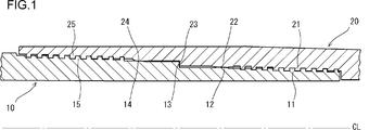
- FIG. 1 is a longitudinal sectional view showing a threaded joint for steel pipes according to an embodiment of the present invention.
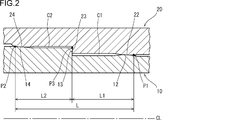
- FIG. 2 is an enlarged vertical cross-sectional view of the vicinity of the boundary of the two-step threaded portion in the steel pipe threaded joint shown in FIG.
- FIG. 3 is an enlarged longitudinal sectional view of the first threaded portion of the steel pipe threaded joint shown in FIG. 4 is an enlarged longitudinal sectional view of a second threaded portion of the steel pipe threaded joint shown in FIG.
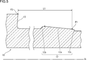
- FIG. 5 is a diagram showing a dimensional relationship between the first seal surface and the shoulder surface in the pin of the present embodiment.
- FIG. 6 is a diagram showing a dimensional relationship between the second seal surface and the shoulder surface in the pin of the present embodiment.
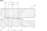
- FIG. 7 is a vertical cross-sectional view schematically showing an area of the inner seal portion due to surface contact.
- FIG. 8 is a longitudinal sectional view schematically showing an area of the outer seal portion by surface contact.
- the thread bottom surface 11b of the first male screw portion 11 and the screw thread top surface 21a of the first female screw portion 21 are in contact with each other, and the screw thread top surface 11a of the first male screw portion 11 and the first A mode in which a gap is formed between the thread valley bottom surface 21 b of the one female screw portion 21 may be used.
Abstract
Description
(i)前記ボックスの外径が前記ピンの管本体の外径の110%未満である。
(ii)前記ピンは、前記ピンの先端から管本体に向けて順に、ダブテイル形状のテーパねじの第1雄ねじ部、第1シール面、ショルダー面、第2シール面、及びダブテイル形状のテーパねじの第2雄ねじ部を備える。
(iii)前記第1シール面は、第1テーパ面と前記第1テーパ面の両端の第1湾曲面とを有する。前記第2シール面は、第2テーパ面と前記第2テーパ面の両端の第2湾曲面とを有する。前記第1テーパ面と前記ピンの先端側の前記第1湾曲面との境界から前記ショルダー面までの管軸方向の距離L1が15mm以上である。前記第2テーパ面と前記ピンの管本体側の前記第2湾曲面との境界から前記ショルダー面までの管軸方向の距離L2が15mm以上である。前記距離L1と前記距離L2の合計距離Lが50mm以上である。
(iv)前記ボックスは、前記ボックスの管本体から先端に向けて順に、ダブテイル形状のテーパねじの第1雌ねじ部、第1シール面、ショルダー面、第2シール面、及びダブテイル形状のテーパねじの第2雌ねじ部を備える。
(v)締結状態において、上記のねじ継手は、
・前記ショルダー面同士が接触し、前記第1シール面同士が接触し、前記第2シール面同士が接触して、
・前記第1雄ねじ部及び前記第1雌ねじ部の挿入フランク面同士の間に隙間が形成されるとともに、前記第1雄ねじ部のねじ谷底面と前記第1雌ねじ部のねじ山頂面との間、又は前記第1雄ねじ部のねじ山頂面と前記第1雌ねじ部のねじ谷底面との間に隙間が形成され、
・前記第2雄ねじ部及び前記第2雌ねじ部の挿入フランク面同士の間に隙間が形成されるとともに、前記第2雄ねじ部のねじ谷底面と前記第2雌ねじ部のねじ山頂面との間、又は前記第2雄ねじ部のねじ山頂面と前記第2雌ねじ部のねじ谷底面との間に隙間が形成される。 A threaded joint for steel pipes according to an embodiment of the present invention is a threaded joint for steel pipes composed of a tubular pin and a tubular box, wherein the pin is screwed into the box and the pin and the box are fastened. The structure like this is included.
(I) The outer diameter of the box is less than 110% of the outer diameter of the tube body of the pin.
(Ii) The pin includes, in order from the tip of the pin toward the pipe body, a first male thread portion of a dovetail-shaped taper screw, a first seal surface, a shoulder surface, a second seal surface, and a dovetail-shaped taper screw. A second male screw portion is provided.
(Iii) The first seal surface includes a first tapered surface and first curved surfaces at both ends of the first tapered surface. The second seal surface has a second tapered surface and second curved surfaces at both ends of the second tapered surface. A distance L1 in the tube axis direction from the boundary between the first tapered surface and the first curved surface on the tip end side of the pin to the shoulder surface is 15 mm or more. A distance L2 in the tube axis direction from the boundary between the second tapered surface and the second curved surface of the pin on the tube main body side to the shoulder surface is 15 mm or more. The total distance L of the distance L1 and the distance L2 is 50 mm or more.
(Iv) The box includes a first female thread portion of a dovetail-shaped taper screw, a first seal surface, a shoulder surface, a second seal surface, and a dovetail-shaped taper screw in order from the tube body to the tip of the box. A second female thread portion is provided.
(V) In the fastened state, the threaded joint is
The shoulder surfaces are in contact with each other, the first seal surfaces are in contact with each other, the second seal surfaces are in contact with each other,
A gap is formed between the insertion flank surfaces of the first male screw portion and the first female screw portion, and between the thread valley bottom surface of the first male screw portion and the screw thread top surface of the first female screw portion, Alternatively, a gap is formed between the screw thread top surface of the first male screw part and the thread valley bottom surface of the first female screw part,
A gap is formed between the insertion flank surfaces of the second male screw portion and the second female screw portion, and between the thread valley bottom surface of the second male screw portion and the screw thread top surface of the second female screw portion, Alternatively, a gap is formed between the screw thread top surface of the second male screw part and the screw valley bottom surface of the second female screw part.
優れた密封性能を確実に発揮できること。 The threaded joint for steel pipes of the present invention has the following remarkable effects:
It must be able to demonstrate excellent sealing performance.
[内シール部と外シール部との間の距離L]
内シール部と外シール部との間の距離Lは50mm以上である。この距離Lが50mm未満であると、締結の過程で内シール部の接触と外シール部の接触とが相互に作用し、かえって密封性能を発揮できない。距離Lの好ましい下限は、55mmである。 Below, the suitable aspect of a main site | part is supplemented.
[Distance L between inner seal and outer seal]
The distance L between the inner seal portion and the outer seal portion is 50 mm or more. If the distance L is less than 50 mm, the contact of the inner seal portion and the contact of the outer seal portion interact with each other in the fastening process, and the sealing performance cannot be exhibited. A preferable lower limit of the distance L is 55 mm.
内シール部からショルダー部までの距離L1、及び外シール部からショルダー部までの距離L2は、内シール部と外シール部との間の距離Lに対する関係で設定され、いずれも15mm以上とする。距離L1、L2が15mm未満であると、シール面の確保が困難になる。距離L1、L2の好ましい下限は、20mmである。 [Distances L1, L2 from the seal portion (inner seal portion and outer seal portion) to the shoulder portion]
The distance L1 from the inner seal portion to the shoulder portion and the distance L2 from the outer seal portion to the shoulder portion are set in relation to the distance L between the inner seal portion and the outer seal portion, and both are set to 15 mm or more. If the distances L1 and L2 are less than 15 mm, it is difficult to secure a sealing surface. A preferable lower limit of the distances L1 and L2 is 20 mm.
管軸に沿った縦断面において、管軸とショルダー面とのなす角度は75~105°とするのが好ましい。その角度が75°を下回ると、ショルダー面同士が、管軸に対して垂直な面からピンのねじ込み進行方向に大きく傾倒し、フック状の形態で押圧接触する状態となる。このため、ショルダー部が塑性変形し易くなり、密封性能が不安定になる。ショルダー面の角度のより好ましい下限は、85°である。 [Shoulder]
In a longitudinal section along the tube axis, the angle formed by the tube axis and the shoulder surface is preferably 75 to 105 °. When the angle is less than 75 °, the shoulder surfaces are greatly tilted from the surface perpendicular to the tube axis in the screwing direction of the pin, and are brought into press contact with each other in a hook-like form. For this reason, the shoulder portion is easily plastically deformed, and the sealing performance becomes unstable. A more preferable lower limit of the angle of the shoulder surface is 85 °.
シール部の領域において、ピン及びボックスのいずれか一方の肉厚があまりに厚いと、それに対応して他方の肉厚が薄くなり、当該他方の剛性が低下する。剛性が低下したピン又はボックスは、耐圧力性能が低下する。したがって、シール部の領域でのピンの肉厚及びボックスの肉厚は、それぞれの管本体の肉厚の45%以上80%以下とするのが好ましい。各肉厚の好ましい下限は、10.5mmである。各肉厚の好ましい上限は、17mmである。 [Seal part (inner seal part and outer seal part)]
In the area of the seal portion, if the thickness of either the pin or the box is too thick, the thickness of the other is correspondingly reduced and the rigidity of the other is lowered. A pin or box having a reduced rigidity has a reduced pressure resistance. Therefore, it is preferable that the thickness of the pin and the thickness of the box in the region of the seal portion be 45% to 80% of the thickness of each pipe body. A preferable lower limit of each thickness is 10.5 mm. A preferable upper limit of each thickness is 17 mm.
ねじ部のテーパは、急勾配にし過ぎると、ねじ部全体の長さが短くなり過ぎて、トルク性能が大幅に低下する。一方、ねじ部のテーパは、緩やかな勾配にし過ぎると、ねじ部全体の長さが増加することから、製造コストが上昇する。したがって、ねじ部のテーパ角は、管軸に対して1.5~4°であることが好ましい。ねじ部のテーパ角のより好ましい下限は、2.0°である。ねじ部のテーパ角のより好ましい上限は、3.6°である。 [Screw (inner thread and outer thread)]
If the taper of the threaded portion is too steep, the entire length of the threaded portion becomes too short, and the torque performance is greatly reduced. On the other hand, if the taper of the threaded portion is too gentle, the length of the entire threaded portion increases, resulting in an increase in manufacturing cost. Accordingly, the taper angle of the threaded portion is preferably 1.5 to 4 ° with respect to the tube axis. A more preferable lower limit of the taper angle of the thread portion is 2.0 °. The upper limit with a more preferable taper angle of a thread part is 3.6 degrees.
FEM解析では、前記図1に示すインテグラル型の鋼管用ねじ継手のモデルを複数作製した。これらのモデルについて、内シール部からショルダー部までの距離L1、及び外シール部からショルダー部までの距離L2を種々変更した。この変更により、内シール部と外シール部との間の距離Lを変更した。更に、ショルダー面の角度も種々変更した。 <Test conditions>
In the FEM analysis, a plurality of models of integral type threaded joints for steel pipes shown in FIG. 1 were prepared. For these models, the distance L1 from the inner seal portion to the shoulder portion and the distance L2 from the outer seal portion to the shoulder portion were variously changed. With this change, the distance L between the inner seal portion and the outer seal portion was changed. Furthermore, the angle of the shoulder surface was also changed variously.


・鋼管の寸法:14[inch]、115[lb/ft](外径が355.6mm、内径が314.35mm、肉厚が20.625mm)
・鋼管のグレード:API規格のQ125(降伏強度が125ksi(862MPa)の炭素鋼) Other common conditions are as follows.
Steel pipe dimensions: 14 [inch], 115 [lb / ft] (outer diameter is 355.6 mm, inner diameter is 314.35 mm, wall thickness is 20.625 mm)
Steel pipe grade: API standard Q125 (carbon steel with yield strength of 125 ksi (862 MPa))
FEM解析では、締結状態の各モデルにISO13679のSeries A試験を模擬した荷重を順次負荷した。その荷重における外シール部(第2シール部)のシール接触力[N/mm]、すなわち「シール面同士の平均接触面圧」×「接触幅」の最小値を比較することにより、外圧に対する密封性能を評価した。接触力の値が高いほどシール部の密封性能が良いことを意味する。同様に、内シール部(第1シール部)でもシール接触力を比較することにより、内圧に対する密封性能を評価した。 <Evaluation method>
In the FEM analysis, a load simulating the ISO 13679 Series A test was sequentially applied to each model in the fastened state. Seal against external pressure by comparing the minimum value of the seal contact force [N / mm] of the outer seal part (second seal part) at that load, that is, “average contact surface pressure between seal surfaces” × “contact width” Performance was evaluated. The higher the contact force value, the better the sealing performance of the seal portion. Similarly, the sealing performance against the internal pressure was evaluated by comparing the sealing contact force in the inner seal portion (first seal portion).
試験結果を下記の表4に示す。 <Test results>
The test results are shown in Table 4 below.

11:第1雄ねじ部、
11a:第1雄ねじ部のねじ山頂面、
11b:第1雄ねじ部のねじ谷底面、
11c:第1雄ねじ部の挿入フランク面、
11d:第1雄ねじ部の荷重フランク面、
12:第1シール面、
12a:第1テーパ面、
12b、12c:第1湾曲面、
13:ショルダー面、
14:第2シール面、
14a:第2テーパ面、
14b、14c:第2湾曲面、
15:第2雄ねじ部、
15a:第2雄ねじ部のねじ山頂面、
15b:第2雄ねじ部のねじ谷底面、
15c:第2雄ねじ部の挿入フランク面、
15d:第2雄ねじ部の荷重フランク面、
20:ボックス、
21:第1雌ねじ部、
21a:第1雌ねじ部のねじ山頂面、
21b:第1雌ねじ部のねじ谷底面、
21c:第1雌ねじ部の挿入フランク面、
21d:第1雌ねじ部の荷重フランク面、
22:第1シール面、
23:ショルダー面、
24:第2シール面、
25:第2雌ねじ部、
25a:第2雌ねじ部のねじ山頂面、
25b:第2雌ねじ部のねじ谷底面、
25c:第2雌ねじ部の挿入フランク面、
25d:第2雌ねじ部の荷重フランク面、
L:第1シール部と第2シール部との間の距離、
L1:第1シール部からショルダー部までの距離、
L2:第2シール部からショルダー部までの距離、
P1:第1テーパ面とピンの先端側の第1湾曲面との境界位置、
P2:第2テーパ面とピンの管本体側の第2湾曲面との境界位置、
P3:ショルダー面同士の接触領域のうちの最小径の位置、
C1:隙間、
C2:隙間、
CL:管軸
10: Pin,
11: 1st male screw part,
11a: Thread top surface of the first male thread portion,
11b: The bottom face of the thread valley of the first male thread part,
11c: Insertion flank surface of the first male screw part,
11d: Load flank surface of the first male thread portion,
12: first sealing surface,
12a: 1st taper surface,
12b, 12c: first curved surface,
13: Shoulder surface
14: Second sealing surface,
14a: second tapered surface,
14b, 14c: second curved surface,
15: Second male screw part,
15a: Thread top surface of the second male thread portion,
15b: the bottom face of the thread valley of the second male thread portion,
15c: Insertion flank surface of the second male screw part,
15d: load flank surface of the second male screw portion,
20: Box
21: 1st female thread part,
21a: Thread top surface of the first female thread portion,
21b: the bottom face of the thread valley of the first female thread part,
21c: insertion flank surface of the first female thread portion,
21d: load flank surface of the first female thread portion,
22: first sealing surface,
23: shoulder surface,
24: second sealing surface,
25: Second female thread portion,
25a: Thread top surface of the second female thread portion,
25b: the bottom face of the thread valley of the second female thread part,
25c: Insertion flank surface of the second female thread portion,
25d: Load flank surface of the second female thread portion,
L: distance between the first seal part and the second seal part,
L1: Distance from the first seal part to the shoulder part,
L2: distance from the second seal part to the shoulder part,
P1: boundary position between the first tapered surface and the first curved surface on the tip end side of the pin;
P2: boundary position between the second tapered surface and the second curved surface of the pin on the tube body side,
P3: the position of the smallest diameter in the contact area between the shoulder surfaces,
C1: gap,
C2: gap,
CL: Tube axis
Claims (5)
- 管状のピンと、管状のボックスとから構成され、前記ピンが前記ボックスにねじ込まれて前記ピンと前記ボックスが締結される鋼管用ねじ継手であって、
前記ボックスの外径が前記ピンの管本体の外径の110%未満であり、
前記ピンは、前記ピンの先端から管本体に向けて順に、ダブテイル形状のテーパねじの第1雄ねじ部、第1シール面、ショルダー面、第2シール面、及びダブテイル形状のテーパねじの第2雄ねじ部を備え、
前記第1シール面は、第1テーパ面と前記第1テーパ面の両端の第1湾曲面とを有し、
前記第2シール面は、第2テーパ面と前記第2テーパ面の両端の第2湾曲面とを有し、
前記第1テーパ面と前記ピンの先端側の前記第1湾曲面との境界から前記ショルダー面までの管軸方向の距離L1が15mm以上であり、
前記第2テーパ面と前記ピンの管本体側の前記第2湾曲面との境界から前記ショルダー面までの管軸方向の距離L2が15mm以上であり、
前記距離L1と前記距離L2の合計距離Lが50mm以上であり、
前記ボックスは、前記ボックスの管本体から先端に向けて順に、ダブテイル形状のテーパねじの第1雌ねじ部、第1シール面、ショルダー面、第2シール面、及びダブテイル形状のテーパねじの第2雌ねじ部を備え、
締結状態において、
前記ショルダー面同士が接触し、前記第1シール面同士が接触し、前記第2シール面同士が接触し、
前記第1雄ねじ部及び前記第1雌ねじ部の挿入フランク面同士の間に隙間が形成されるとともに、前記第1雄ねじ部のねじ谷底面と前記第1雌ねじ部のねじ山頂面との間、又は前記第1雄ねじ部のねじ山頂面と前記第1雌ねじ部のねじ谷底面との間に隙間が形成され、
前記第2雄ねじ部及び前記第2雌ねじ部の挿入フランク面同士の間に隙間が形成されるとともに、前記第2雄ねじ部のねじ谷底面と前記第2雌ねじ部のねじ山頂面との間、又は前記第2雄ねじ部のねじ山頂面と前記第2雌ねじ部のねじ谷底面との間に隙間が形成される、鋼管用ねじ継手。 A steel pipe threaded joint comprising a tubular pin and a tubular box, wherein the pin is screwed into the box and the pin and the box are fastened.
The outer diameter of the box is less than 110% of the outer diameter of the tube body of the pin;
The pin has a first male screw portion of a dovetail taper screw, a first seal surface, a shoulder surface, a second seal surface, and a second male screw of a dovetail taper screw in order from the tip of the pin toward the tube body. Part
The first sealing surface has a first tapered surface and first curved surfaces at both ends of the first tapered surface,
The second seal surface has a second tapered surface and second curved surfaces at both ends of the second tapered surface,
The distance L1 in the tube axis direction from the boundary between the first tapered surface and the first curved surface on the tip end side of the pin to the shoulder surface is 15 mm or more,
The distance L2 in the tube axis direction from the boundary between the second tapered surface and the second curved surface on the tube main body side of the pin to the shoulder surface is 15 mm or more,
The total distance L of the distance L1 and the distance L2 is 50 mm or more,
The box has a first female threaded portion of a dovetail-shaped taper screw, a first seal surface, a shoulder surface, a second seal surface, and a second female screw of a dovetail-shaped taper screw in order from the tube body to the tip of the box. Part
In the fastened state
The shoulder surfaces are in contact with each other, the first sealing surfaces are in contact with each other, the second sealing surfaces are in contact with each other,
A gap is formed between the insertion flank surfaces of the first male screw portion and the first female screw portion, and between the thread valley bottom surface of the first male screw portion and the screw thread top surface of the first female screw portion, or A gap is formed between the screw thread top surface of the first male thread part and the thread valley bottom surface of the first female thread part,
A gap is formed between the insertion flank surfaces of the second male screw portion and the second female screw portion, and between the thread valley bottom surface of the second male screw portion and the screw thread top surface of the second female screw portion, or A threaded joint for steel pipes, in which a gap is formed between the top surface of the second threaded portion and the bottom surface of the threaded portion of the second threaded portion. - 請求項1に記載の鋼管用ねじ継手であって、
前記ねじ山頂面と前記ねじ谷底面との間の前記隙間が0.10mm以上0.20mm未満である、鋼管用ねじ継手。 A threaded joint for steel pipes according to claim 1,
A threaded joint for steel pipes, wherein the gap between the screw thread top surface and the thread valley bottom surface is 0.10 mm or more and less than 0.20 mm. - 請求項1又は2に記載の鋼管用ねじ継手であって、
管軸に沿った縦断面において、管軸と前記ショルダー面とのなす角度が75~105°である、鋼管用ねじ継手。 A threaded joint for steel pipes according to claim 1 or 2,
A threaded joint for steel pipes, wherein an angle formed by the pipe axis and the shoulder surface is 75 to 105 ° in a longitudinal section along the pipe axis. - 請求項1~3のいずれか1項に記載の鋼管用ねじ継手であって、
前記合計距離Lが90mm以下である、鋼管用ねじ継手。 A threaded joint for steel pipes according to any one of claims 1 to 3,
A threaded joint for steel pipes, wherein the total distance L is 90 mm or less. - 請求項1~4のいずれか1項に記載の鋼管用ねじ継手であって、
前記第1雄ねじ部と前記第1雌ねじ部で構成される第1ねじ部、及び前記第2雄ねじ部と前記第2雌ねじ部で構成される第2ねじ部が、1条ねじ又は2条ねじである、鋼管用ねじ継手。
A threaded joint for steel pipes according to any one of claims 1 to 4,
The 1st thread part which consists of the 1st external thread part and the 1st internal thread part, and the 2nd thread part which consists of the 2nd external thread part and the 2nd internal thread part are single thread screws or double thread threads There is a threaded joint for steel pipes.
Priority Applications (13)
| Application Number | Priority Date | Filing Date | Title |
|---|---|---|---|
| CN201680082274.7A CN108700230B (en) | 2016-02-23 | 2016-02-23 | Screw joint for steel pipe |
| EA201891896A EA033926B1 (en) | 2016-02-23 | 2016-02-23 | Threaded joint for steel pipes |
| AU2016394560A AU2016394560B2 (en) | 2016-02-23 | 2016-02-23 | Threaded joint for steel pipes |
| US16/078,172 US10883632B2 (en) | 2016-02-23 | 2016-02-23 | Threaded joint for steel pipes |
| UAA201809474A UA119839C2 (en) | 2016-02-23 | 2016-02-23 | Threaded joint for steel pipes |
| JP2018501395A JP6577654B2 (en) | 2016-02-23 | 2016-02-23 | Threaded joints for steel pipes |
| PL16891355T PL3421855T3 (en) | 2016-02-23 | 2016-02-23 | Threaded joint for steel pipes |
| MX2018010074A MX2018010074A (en) | 2016-02-23 | 2016-02-23 | Threaded joint for steel pipes. |
| CA3015307A CA3015307C (en) | 2016-02-23 | 2016-02-23 | Threaded joint for steel pipes |
| PCT/JP2016/000963 WO2017145192A1 (en) | 2016-02-23 | 2016-02-23 | Threaded joint for steel pipes |
| BR112018015968-9A BR112018015968B1 (en) | 2016-02-23 | 2016-02-23 | threaded joint for steel pipes |
| MYPI2018702710A MY195221A (en) | 2016-02-23 | 2016-02-23 | Threaded Joint for Steel Pipes |
| EP16891355.6A EP3421855B1 (en) | 2016-02-23 | 2016-02-23 | Threaded joint for steel pipes |
Applications Claiming Priority (1)
| Application Number | Priority Date | Filing Date | Title |
|---|---|---|---|
| PCT/JP2016/000963 WO2017145192A1 (en) | 2016-02-23 | 2016-02-23 | Threaded joint for steel pipes |
Publications (1)
| Publication Number | Publication Date |
|---|---|
| WO2017145192A1 true WO2017145192A1 (en) | 2017-08-31 |
Family
ID=59684879
Family Applications (1)
| Application Number | Title | Priority Date | Filing Date |
|---|---|---|---|
| PCT/JP2016/000963 WO2017145192A1 (en) | 2016-02-23 | 2016-02-23 | Threaded joint for steel pipes |
Country Status (13)
| Country | Link |
|---|---|
| US (1) | US10883632B2 (en) |
| EP (1) | EP3421855B1 (en) |
| JP (1) | JP6577654B2 (en) |
| CN (1) | CN108700230B (en) |
| AU (1) | AU2016394560B2 (en) |
| BR (1) | BR112018015968B1 (en) |
| CA (1) | CA3015307C (en) |
| EA (1) | EA033926B1 (en) |
| MX (1) | MX2018010074A (en) |
| MY (1) | MY195221A (en) |
| PL (1) | PL3421855T3 (en) |
| UA (1) | UA119839C2 (en) |
| WO (1) | WO2017145192A1 (en) |
Cited By (2)
| Publication number | Priority date | Publication date | Assignee | Title |
|---|---|---|---|---|
| WO2021059807A1 (en) * | 2019-09-24 | 2021-04-01 | 日本製鉄株式会社 | Screw-threaded joint |
| US11505999B2 (en) * | 2020-10-22 | 2022-11-22 | Frac String Solutions Llc | Leak-resistant threaded pipe connection |
Families Citing this family (7)
| Publication number | Priority date | Publication date | Assignee | Title |
|---|---|---|---|---|
| UA123130C2 (en) * | 2017-11-09 | 2021-02-17 | Ніппон Стіл Корпорейшн | Threaded joint for steel pipes |
| FR3098878B1 (en) * | 2019-07-19 | 2021-07-30 | Vallourec Oil & Gas France | Threaded joint for oil well casing column |
| FR3098879B1 (en) | 2019-07-19 | 2021-07-30 | Vallourec Oil & Gas France | Threaded joint with asymmetrical helical profile |
| CN114207303B (en) * | 2019-08-01 | 2023-11-21 | 伊顿智能动力有限公司 | Hybrid thread geometry for threaded pipe elements |
| CN114026309B (en) * | 2019-08-09 | 2023-06-20 | 日本制铁株式会社 | Threaded joint for steel pipe |
| MX2022003070A (en) * | 2020-01-17 | 2022-04-18 | Nippon Steel Corp | Threaded coupling for pipe. |
| CN114761722B (en) * | 2020-01-17 | 2024-01-02 | 日本制铁株式会社 | Threaded joint for pipe |
Citations (5)
| Publication number | Priority date | Publication date | Assignee | Title |
|---|---|---|---|---|
| JPS60500457A (en) * | 1983-01-17 | 1985-04-04 | ハイドリル カンパニ− | Tubular fittings with metal-to-metal seals |
| US20060145480A1 (en) | 2004-12-30 | 2006-07-06 | Hydril Company | Floating wedge thread for tubular connection |
| US7690696B2 (en) | 1999-04-19 | 2010-04-06 | Hydril Company | Wedge thread with torque shoulder |
| JP2013536339A (en) * | 2010-08-23 | 2013-09-19 | ヴァルレック・マンネスマン・オイル・アンド・ガス・フランス | Tubular screw connection |
| WO2014045973A1 (en) * | 2012-09-21 | 2014-03-27 | 新日鐵住金株式会社 | Threaded joint for steel pipe |
Family Cites Families (11)
| Publication number | Priority date | Publication date | Assignee | Title |
|---|---|---|---|---|
| US4893844A (en) * | 1983-04-29 | 1990-01-16 | Baker Hughes Incorporated | Tubular coupling with ventable seal |
| US4822081A (en) | 1987-03-23 | 1989-04-18 | Xl Systems | Driveable threaded tubular connection |
| US5066052A (en) * | 1989-03-08 | 1991-11-19 | Baroid Technology, Inc. | Threaded pipe joint having improved seal ring entrapment |
| US5415442A (en) * | 1992-03-09 | 1995-05-16 | Marubeni Tubulars, Inc. | Stabilized center-shoulder-sealed tubular connection |
| US5687999A (en) * | 1995-10-03 | 1997-11-18 | Vallourec Oil & Gas | Threaded joint for tubes |
| IT1309704B1 (en) * | 1999-02-19 | 2002-01-30 | Eni Spa | INTEGRAL JUNCTION OF TWO PIPES |
| ES2394032T3 (en) * | 1999-04-30 | 2013-01-15 | Grant Prideco, Inc | Threaded connection with high compression rate |
| FR2800150B1 (en) * | 1999-10-21 | 2001-12-07 | Vallourec Mannesmann Oil & Gas | EXTERNAL PRESSURE THREADED TUBULAR JOINT |
| UA82694C2 (en) * | 2003-06-06 | 2008-05-12 | Sumitomo Metal Ind | Threaded joint for steel pipes |
| US7690697B2 (en) | 2007-05-09 | 2010-04-06 | Gandy Technologies Corp. | Thread form for tubular connections |
| US9388925B2 (en) * | 2013-02-05 | 2016-07-12 | Ultra Premium Oilfield Services, Ltd | Tubular connection center shoulder seal |
-
2016
- 2016-02-23 US US16/078,172 patent/US10883632B2/en active Active
- 2016-02-23 UA UAA201809474A patent/UA119839C2/en unknown
- 2016-02-23 BR BR112018015968-9A patent/BR112018015968B1/en active IP Right Grant
- 2016-02-23 PL PL16891355T patent/PL3421855T3/en unknown
- 2016-02-23 MX MX2018010074A patent/MX2018010074A/en unknown
- 2016-02-23 CA CA3015307A patent/CA3015307C/en active Active
- 2016-02-23 CN CN201680082274.7A patent/CN108700230B/en active Active
- 2016-02-23 AU AU2016394560A patent/AU2016394560B2/en not_active Ceased
- 2016-02-23 EP EP16891355.6A patent/EP3421855B1/en active Active
- 2016-02-23 JP JP2018501395A patent/JP6577654B2/en active Active
- 2016-02-23 WO PCT/JP2016/000963 patent/WO2017145192A1/en active Application Filing
- 2016-02-23 MY MYPI2018702710A patent/MY195221A/en unknown
- 2016-02-23 EA EA201891896A patent/EA033926B1/en not_active IP Right Cessation
Patent Citations (5)
| Publication number | Priority date | Publication date | Assignee | Title |
|---|---|---|---|---|
| JPS60500457A (en) * | 1983-01-17 | 1985-04-04 | ハイドリル カンパニ− | Tubular fittings with metal-to-metal seals |
| US7690696B2 (en) | 1999-04-19 | 2010-04-06 | Hydril Company | Wedge thread with torque shoulder |
| US20060145480A1 (en) | 2004-12-30 | 2006-07-06 | Hydril Company | Floating wedge thread for tubular connection |
| JP2013536339A (en) * | 2010-08-23 | 2013-09-19 | ヴァルレック・マンネスマン・オイル・アンド・ガス・フランス | Tubular screw connection |
| WO2014045973A1 (en) * | 2012-09-21 | 2014-03-27 | 新日鐵住金株式会社 | Threaded joint for steel pipe |
Cited By (5)
| Publication number | Priority date | Publication date | Assignee | Title |
|---|---|---|---|---|
| WO2021059807A1 (en) * | 2019-09-24 | 2021-04-01 | 日本製鉄株式会社 | Screw-threaded joint |
| JPWO2021059807A1 (en) * | 2019-09-24 | 2021-04-01 | ||
| JP7290738B2 (en) | 2019-09-24 | 2023-06-13 | 日本製鉄株式会社 | threaded joint |
| US11828391B2 (en) | 2019-09-24 | 2023-11-28 | Nippon Steel Corporation | Threaded connection |
| US11505999B2 (en) * | 2020-10-22 | 2022-11-22 | Frac String Solutions Llc | Leak-resistant threaded pipe connection |
Also Published As
| Publication number | Publication date |
|---|---|
| EP3421855A1 (en) | 2019-01-02 |
| JPWO2017145192A1 (en) | 2018-11-08 |
| BR112018015968A2 (en) | 2018-12-18 |
| MX2018010074A (en) | 2019-01-21 |
| AU2016394560B2 (en) | 2019-10-03 |
| MY195221A (en) | 2023-01-11 |
| EA201891896A1 (en) | 2019-02-28 |
| US20190040978A1 (en) | 2019-02-07 |
| CN108700230A (en) | 2018-10-23 |
| BR112018015968B1 (en) | 2021-02-02 |
| CN108700230B (en) | 2019-11-22 |
| AU2016394560A1 (en) | 2018-09-20 |
| EA033926B1 (en) | 2019-12-10 |
| PL3421855T3 (en) | 2020-12-14 |
| CA3015307A1 (en) | 2017-08-31 |
| UA119839C2 (en) | 2019-08-12 |
| EP3421855B1 (en) | 2020-07-22 |
| JP6577654B2 (en) | 2019-09-18 |
| CA3015307C (en) | 2020-02-18 |
| US10883632B2 (en) | 2021-01-05 |
| EP3421855A4 (en) | 2019-10-30 |
Similar Documents
| Publication | Publication Date | Title |
|---|---|---|
| JP6577654B2 (en) | Threaded joints for steel pipes | |
| EP3205918B1 (en) | Threaded joint for steel pipes | |
| JP6239111B2 (en) | Threaded joints for steel pipes | |
| JP6654643B2 (en) | Screw joints for steel pipes | |
| WO2015105054A1 (en) | Threaded joint for steel pipe | |
| AU2007232748A1 (en) | Tubular threaded joint | |
| JP6683738B2 (en) | Threaded joint for steel pipe | |
| WO2019093163A1 (en) | Threaded joint for steel pipes | |
| WO2015194193A1 (en) | Threaded coupling for steel piping | |
| WO2021059807A1 (en) | Screw-threaded joint | |
| JP5803953B2 (en) | Threaded joint for pipe connection | |
| WO2018216375A1 (en) | Threaded joint for steel pipes |
Legal Events
| Date | Code | Title | Description |
|---|---|---|---|
| WWE | Wipo information: entry into national phase |
Ref document number: 2018501395 Country of ref document: JP |
|
| REG | Reference to national code |
Ref country code: BR Ref legal event code: B01A Ref document number: 112018015968 Country of ref document: BR |
|
| WWE | Wipo information: entry into national phase |
Ref document number: MX/A/2018/010074 Country of ref document: MX Ref document number: 3015307 Country of ref document: CA |
|
| NENP | Non-entry into the national phase |
Ref country code: DE |
|
| ENP | Entry into the national phase |
Ref document number: 2016394560 Country of ref document: AU Date of ref document: 20160223 Kind code of ref document: A |
|
| WWE | Wipo information: entry into national phase |
Ref document number: 201891896 Country of ref document: EA |
|
| WWE | Wipo information: entry into national phase |
Ref document number: 2016891355 Country of ref document: EP |
|
| ENP | Entry into the national phase |
Ref document number: 2016891355 Country of ref document: EP Effective date: 20180924 |
|
| 121 | Ep: the epo has been informed by wipo that ep was designated in this application |
Ref document number: 16891355 Country of ref document: EP Kind code of ref document: A1 |
|
| ENP | Entry into the national phase |
Ref document number: 112018015968 Country of ref document: BR Kind code of ref document: A2 Effective date: 20180803 |